Stonesoft (Stone Gate) IPS-3200 Series Appliance ... · • Do not use mats designed to decrease...
43
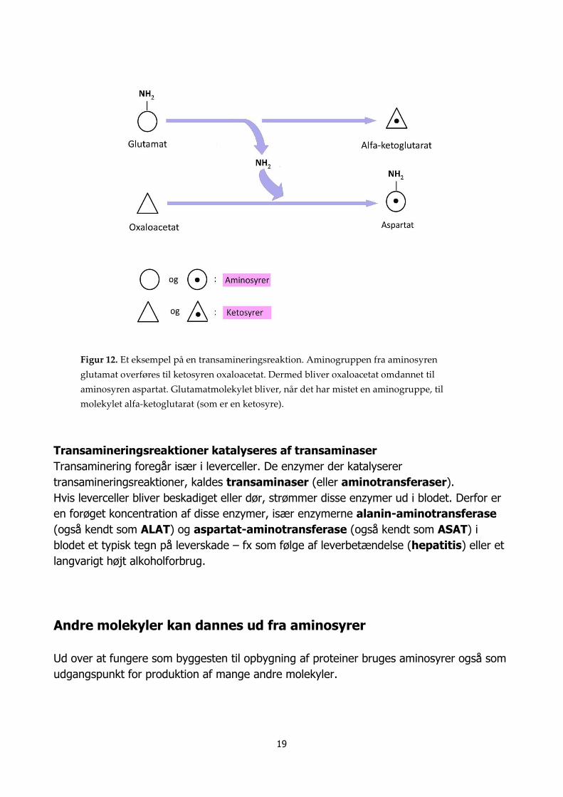
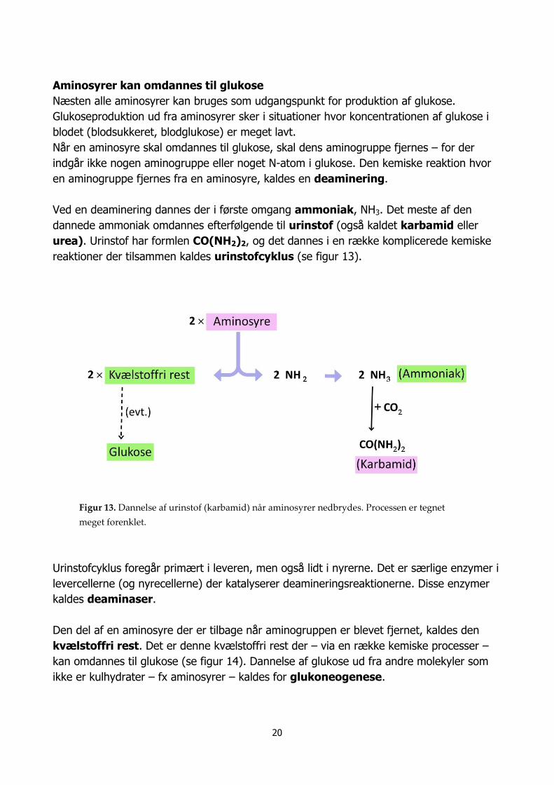
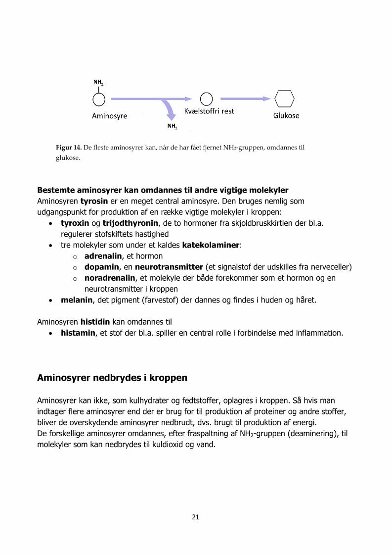
Danish University Colleges Proteiner, aminosyrer og kulhydrater Mikkelsen, Thomas Raundahl; Andersen, Kirsten Bak Publication date: 2012 Document Version Post-print: Den endelige version af artiklen, der er accepteret, redigeret og fagfællebedømt (peer-review) af udgiveren, men uden udgiverens layout. Link to publication Citation for pulished version (APA): Mikkelsen, T. R., & Andersen, K. B. (2012). Proteiner, aminosyrer og kulhydrater. General rights Copyright and moral rights for the publications made accessible in the public portal are retained by the authors and/or other copyright owners and it is a condition of accessing publications that users recognise and abide by the legal requirements associated with these rights. • Users may download and print one copy of any publication from the public portal for the purpose of private study or research. • You may not further distribute the material or use it for any profit-making activity or commercial gain • You may freely distribute the URL identifying the publication in the public portal Download policy If you believe that this document breaches copyright please contact us providing details, and we will remove access to the work immediately and investigate your claim. Download date: 02. Jun. 2019
Transcript of Stonesoft (Stone Gate) IPS-3200 Series Appliance ... · • Do not use mats designed to decrease...
Appliance I
IPS-320
nstallation Guide
0 Series

Legal Information
End-User License AgreementThe use of the products described in these materials is subject to the then current end-user license agreement, which can be found at the Stonesoft website:www.stonesoft.com/en/support/eula.html
Third Party LicensesThe Stonesoft software includes several open source or third-party software packages. The appropriate software licensing information for those products at the Stonesoft website:www.stonesoft.com/en/support/third_party_licenses.html
U.S. Government AcquisitionsIf Licensee is acquiring the Software, including accompanying documentation on behalf of the U.S. Government, the following provisions apply. If the Software is supplied to the Department of Defense (“DoD”), the Software is subject to “Restricted Rights”, as that term is defined in the DOD Supplement to the Federal Acquisition Regulations (“DFAR”) in paragraph 252.227-7013(c) (1). If the Software is supplied to any unit or agency of the United States Government other than DOD, the Government’s rights in the Software will be as defined in paragraph 52.227-19(c) (2) of the Federal Acquisition Regulations (“FAR”). Use, duplication, reproduction or disclosure by the Government is subject to such restrictions or successor provisions.
Product Export RestrictionsThe products described in this document are subject to export control under the laws of Finland and the European Council Regulation (EC) N:o 1334/2000 of 22 June 2000 setting up a Community regime for the control of exports of dual-use items and technology (as amended). Thus, the export of this Stonesoft software in any manner is restricted and requires a license by the relevant authorities.
General Terms and Conditions of Support and Maintenance ServicesThe support and maintenance services for the products described in these materials are provided pursuant to the general terms for support and maintenance services and the related service description, which can be found at the Stonesoft website:www.stonesoft.com/en/support/view_support_offering/terms/
Replacement ServiceThe instructions for replacement service can be found at the Stonesoft website:www.stonesoft.com/en/support/view_support_offering/return_material_authorization/
Hardware WarrantyThe appliances described in these materials have a limited hardware warranty. The terms of the hardware warranty can be found at the Stonesoft website:www.stonesoft.com/en/support/view_support_offering/warranty_service/
Trademarks and PatentsThe products described in these materials are protected by one or more of the following European and US patents: European Patent Nos. 1065844, 1189410, 1231538, 1259028, 1271283, 1289183, 1289202, 1304849, 1313290, 1326393, 1379046, 1330095, 131711, 1317937 and 1443729 and US Patent Nos. 6,650,621; 6 856 621; 6,885,633; 6,912,200; 6,996,573; 7,099,284; 7,127,739; 7,130,266; 7,130,305; 7,146,421; 7,162,737; 7,234,166; 7,260,843; 7,280,540; 7,302,480; 7,386,525; 7,406,534; 7,461,401; 7,721,084; and 7,739,727 and may be protected by other EU, US, or other patents, or pending applications. Stonesoft, the Stonesoft logo and StoneGate, are all trademarks or registered trademarks of Stonesoft Corporation. All other trademarks or registered trademarks are property of their respective owners.
DisclaimerAlthough every precaution has been taken to prepare these materials, THESE MATERIALS ARE PROVIDED "AS-IS" and Stonesoft makes no warranty to the correctness of information and assumes no responsibility for errors, omissions, or resulting damages from the use of the information contained herein. All IP addresses in these materials were chosen at random and are used for illustrative purposes only.
Copyright © 2012 Stonesoft Corporation. All rights reserved. All specifications are subject to change.
Revision: SGAIG_IPS-3200_Series_20120223
2

IntroductionThank you for choosing a Stonesoft™ appliance. This guide provides instructions for the initial hardware installation and the maintenance of the IPS-3200 Series appliances. See Product Documentation (page 5) for information on other available documentation.The use of the appliance is subject to the acceptance of the End User License Agreement, which can be found at the Stonesoft website.
Contents
Installation Procedure .............................4 Product Documentation ...........................5 Safety Precautions ..................................5 Unpacking the Appliance .........................8 Front Panel .............................................9 Back Panel .............................................12 Installing the Solid State Disk ..................13 Installing Interface Modules.....................14 Rack-Mounting........................................15 Connecting the Cables ............................21 Initial Configuration .................................25 Command-Line Management....................34 Maintenance Operations..........................34 Disposal Instructions ..............................39
Caution – Read the Safety Precautions (page 5) before you conduct any installation or maintenance operations on the appliance.
Introduction 3

Instal lation Procedure
The appliance installation involves the following mandatory steps:1. Configure the IPS element in the Management Client, and save
the initial configuration on a USB memory stick. See the IPS Installation Guide.
2. If the Solid State Disk (SSD) is not pre-installed in the appliance, install the SSD. See Installing the Solid State Disk (page 13).
3. Install an interface module in each slot on the appliance. See Installing Interface Modules (page 14).
4. Install the appliance into a rack and connect the cables. See Rack-Mounting (page 15) and Connecting the Cables (page 21).
5. Insert the USB memory stick in a USB port on the appliance, and turn on the appliance to import the initial configuration. See Initial Configuration (page 25).
Note – You must have a working Management Center on a separate server to bring the appliance(s) operational. See the Stonesoft Management Center Installation Guide.
Management Client
Management Server
Initial Configuration
File
USB Memory Stick
Appliance SSD
Appliance Interface Modules
Appliance USB Memory Stick
4 Installation Procedure
Product DocumentationPress F1 in any Management Client window to view the Online Help.All PDF guides are available:• On the Management Center CD-ROM (in the Documentation folder)• At the Stonesoft website at http://www.stonesoft.com/en/support/
technical_support_and_documents/manuals/Install the free Adobe Reader program to view the PDF documents (available at www.adobe.com/reader/).
Safety PrecautionsFollow these safety precautions whenever working with electronic equipment.
Electrical Safety PrecautionsBasic electrical safety precautions should be followed to protect yourself from harm and the appliance from damage:• Be aware of the location of the power on/off switch as well as the
room's emergency power-off switch, disconnection switch, or electrical outlet. If an electrical accident occurs, you can then quickly cut power to the system.
• Do not work alone when working with high-voltage components. • Before removing or installing main system components, be sure to
disconnect the power first. Turn off the system before you disconnect the power cord.
• Use only one hand when working with powered-on electrical equipment. This is to avoid making a complete circuit, which will cause electrical shock. Use extreme caution when using metal tools, which can easily damage any electrical components or circuit boards they come into contact with.
• Do not use mats designed to decrease electrostatic discharge as protection from electrical shock. Instead, use rubber mats that have been specifically designed as electrical insulators.
• The power supply cord must include a grounding plug and must be plugged into a grounded electrical outlet. Use only the cord supplied with the appliance.
• The power cord plug cap that plugs into the AC receptacle on the power supply must be an IEC 320, sheet C13, type female connector.
Product Documentation 5
• If you have to replace the motherboard battery, install it the same way as the original battery. Make sure that the positive side faces up on the motherboard. This battery must be replaced only with the same or an equivalent type recommended by the manufacturer. Dispose of used batteries according to the manufacturer's instructions.
• Do not open the enclosures of power supplies or SSD Drive to avoid injury.
General Safety PrecautionsFollow these rules to ensure general safety:• Keep the area around the appliance clean and free of clutter.• The appliance weighs approximately 13 kg (29 lbs.) when fully
loaded. When lifting the appliance, two people at either end should lift slowly with their feet spread out to distribute the weight. Always keep your back straight and lift with your legs.
• We recommend using a regulating uninterruptible power supply (UPS) to protect the appliance from power surges, voltage spikes and to keep your system operating in case of a power failure.
Power Supplies
Appliances with DC Power Supply• The appliance must be used in a Restricted Access Location and the
users must be well-trained to operate it.• The socket-outlet for pluggable equipment must be installed near the
equipment and must be easily accessible.• Appliance inlet must have SPS approval or have min. 15 AWG wire
provided for the power supply.• The Mains Supply plug on the power supply cord is the disconnect
device of the appliance. To disconnect the appliance, you must first disconnect the mains and then disconnect the ground.
Appliances with AC Power Supply• The appliance inlet is the disconnect device.
6 Safety Precautions

ESD PrecautionsElectrostatic discharge (ESD) is generated by two objects with different electrical charges coming into contact with each other. An electrical discharge is created to neutralize this difference, which can damage electronic components and printed circuit boards. Use a grounded wrist strap designed to prevent static discharge.
Laser PrecautionsClass 1 Laser Product
Operating PrecautionsCare must be taken to assure that the appliance cover is in place when the appliance is operating to ensure proper cooling. If this rule is not strictly followed, the warranty may become void. Do not open the power supply casing. Power supplies can only be accessed and serviced by a qualified technician of the manufacturer.
Operating and Storage TemperaturesThe allowed operating temperature of the appliance is +5...+35ºC. The allowed storage temperature is -20...+65ºC. Do not operate or store the appliance in temperatures outside these limits. If the appliance or the interface modules have been stored in temperatures below 0ºC or above +40ºC, allow for 2 hours to bring the appliance and the modules to normal operating temperature before turning on the appliance. Otherwise, the appliance or the modules may be damaged.
Note – Use a UPS (Uninterruptible Power Supply) in critical environments with your Stonesoft appliance. If after a brief power outage your appliance only partially starts up (for example, the power light is on, but the NIC LEDs are off and the appliance does not connect) turn the appliance off for five seconds and then back on.
Caution – Invisible laser radiation is emitted from the end of fiber cable and from aperture of the port when no fiber cable is connected. Do not stare into the beam and avoid direct exposure to the beam.
Safety Precautions 7
Lithium Battery Precautions
For California:Perchlorate Material - special handling may apply. See www.dtsc.ca.gov/hazardouswaste/perchlorate.This notice is required by California Code of Regulations, Title 22, Division 4.5, Chapter 33: Best Management Practices for Perchlorate Materials. This product/part includes a battery that contains Perchlorate material.
Unpacking the ApplianceInspect the box the appliance was shipped in and any other boxes included in the delivery. If the Solid State Disk (SSD) is not pre-installed in the appliance, the SSD is delivered in a separate box. The interface modules are always delivered in separate boxes. Note if any of the boxes are damaged in any way. If the appliance itself or any components delivered with the appliance show any damage, file a damage claim with the carrier who delivered the appliance or the components.Do not remove the anti-tamper tapes on any part of the appliance.
Caution – The battery must be replaced by authorized service personnel only. Danger of explosion if battery is incorrectly replaced. Replacement battery must be same or equivalent type recommended by the manufacturer. Used batteries must be discarded according to the manufacturer’s instructions. Short-circuiting the battery may heat the battery and cause severe injuries.
8 Unpacking the Appliance

Front Panel
On the front panel, there are slots for the interface modules, a Solid State Disk (SSD) Drive, two USB ports, and a serial port. There are two more USB ports on the back panel of the appliance. See Back Panel (page 12).The front panel also has six LED indicators and the Power button. The status of the Power button and all the indicators on the front panel (including the indicators for the SSD Drive) are explained below. See the separate Interface Module Guide delivered with the appliance for information on the port indicators for the interface modules.
Power Button
Table 1 Power Status
Status Explanation
GreenIndicates power is being supplied to the system's power supply unit. This LED is illuminated when the system is operating normally.
Slots for Interface Modules
USB Ports
Serial Port
SSD Drive
Power Button
LED Indicators
Front Panel 9
LED IndicatorsThe front panel has six LED indicators in the upper right corner. The LEDs provide you with critical information related to different parts of the system.
Table 2 Front Panel LEDs
Indicates that a power supply cable is detached.
When flashing, indicates a fan failure.When continuously on, indicates an overheat condition, which may be caused by cables obstructing the airflow in the system or the ambient room temperature being too warm.
Indicates network activity on the onboard Ethernet interface 1 when flashing (the interface is on the back panel of the appliance).
Indicates network activity on the onboard Ethernet interface 0 when flashing (the interface is on the back panel of the appliance).
Indicates hard drive activity when flashing.
Indicates power is being supplied to the system's power supply units. This LED is illuminated when the system is operating normally.
10 Front Panel
SSD Drive IndicatorsThe indicators for the Solid State Disk (SSD) Drive are explained below.
Table 3 SSD Drive Indicators
Indicator Status Explanation
Power Blue A Solid State Disk is in the drive.
Disk Unlit This indicator is not currently used.
Disk
Power
Front Panel 11
Back Panel
The connectors and ports on the back panel are explained in Connecting the Cables (page 21).The LED indicators for the two fixed Ethernet ports are explained below.Fixed Ports
Table 4 Indicators for Fixed Ports
Indicator Color Explanation
Activity Yellow Link ok, blinks on activity.
Link
Unlit No link or the speed is 10 Mbps.
Green Speed is 100 Mbps.
Amber Speed is 1 Gbps.
AC or DC Power Connectors
Ethernet PortsVGA PortTwo USB Ports
Serial Port (Not used)
IPMI Port (Use not supported
Activity Link
12 Back Panel
Instal l ing the Solid State DiskIf the Solid State Disk (SSD) is not pre-installed in the appliance, you must first install the SSD.
To install the Solid State Disk1. Locate the Solid State Disk included in the delivery package.2. Locate the Solid State Disk Drive on the appliance’s back panel
(see the illustration in Back Panel (page 12)).3. Press the release button on the Solid State Disk to release the
lever on the disk.
4. Insert the disk into the drive.5. Press the lever down to lock the disk into position.Proceed to Installing Interface Modules (page 14).
Caution – We recommend using a grounding strap when handling an SSD. Uninstalled SSDs are sensitive to ESD damage.
Release buttonLever
Installing the Solid State Disk 13

Instal l ing Interface ModulesThis section provides information on installing Stonesoft interface modules into the appliance. You must install an interface module or a placeholder module in each slot before you can make the appliance operational. The process of installing an interface module is the same for all module types.Read the Safety Precautions (page 5) before proceeding.
To install an interface module1. Make sure that the appliance is turned off and that no cables are
connected to the appliance or to wall outlets.2. (Recommended) Fasten a grounding strap to your wrist so that it
contacts your bare skin and attach the other end of the strap to the appliance.
3. Select the slot where you want to install the interface module.4. Push the module into the slot the sticker side up until the front
panel of the module is even with the front panel of the appliance.
5. Repeat steps 3 and 4 until you have installed an interface module in each slot.• You must install an interface module in each slot before you can
configure the appliance.Proceed to Rack-Mounting (page 15).
Caution – Do not install or remove interface modules if the appliance is powered on to avoid damaging modules and modular appliances.
Caution – Do not insert the interface module upside down. Inserting the modules incorrectly may damage the appliance and the modules and will void the warranty.
14 Installing Interface Modules
Rack-MountingThis section provides information on installing the Stonesoft appliance into a rack unit. You can install the appliance into a two-post or a four-post rack unit.
Preparing for Rack-MountingThe appliance delivery includes the rail assemblies and the mounting screws you need to install the system into the rack.Read the sections below before you begin the installation.
Choosing a Setup LocationDecide on a suitable location for the rack unit that will hold the appliance:• The appliance must be situated in a clean, dust-free area that is well
ventilated.• Avoid areas where heat, electrical noise and electromagnetic fields
are generated.• Leave enough clearance in front of the rack to enable you to open the
front door completely (~63 cm/25 inches).• Leave enough clearance in the back of the rack to allow for sufficient
airflow and ease in servicing (~76 cm/30 inches).
Rack Precautions• Ensure that the leveling jacks on the bottom of the rack are fully
extended to the floor with the full weight of the rack resting on them.• In single rack installation, attach stabilizers to the rack.• In multiple rack installations, couple the racks together.• Always make sure the rack is stable before extending a component
from the rack.• Extend only one component at a time—extending two or more
simultaneously may cause the rack to become unstable.
Appliance Precautions• Determine the placement of each component in the rack before you
install the rails.• Install the heaviest components on the bottom of the rack first, and
then work up.
Caution – Read the Safety Precautions (page 5) before proceeding.
Rack-Mounting 15
• The appliance must be connected to a grounded power outlet.• Use a regulating uninterruptible power supply (UPS) to protect the
appliance from power surges, voltage spikes and to keep your system operating in case of a power failure.
• Always keep the rack's front door and all panels and components on the appliances closed when not servicing to maintain proper cooling.
Before Installing the Appliance Into a Rack• Make sure that the rack is securely anchored onto an unmovable
surface or structure before installing the appliance into the rack.• Unplug the power cord(s) of the rack before installing the appliance
into the rack.• Make sure that the system is adequately supported. Make sure that
all the components are securely fastened to the appliance to prevent components falling off from the appliance.
• Be sure to install an AC power disconnect for the entire rack assembly. This power disconnect must be clearly marked.
• The rack assembly shall be properly grounded to avoid electric shock.• The rack assembly must provide sufficient airflow to the appliance for
proper cooling.
Installing the Appliance into a Rack
This section provides information on installing the appliance into a rack unit. There are a variety of rack units on the market, so the assembly procedure may differ slightly from what is instructed. If necessary, refer to the instructions that came with the rack unit you are using.If you are installing the appliance into a Telco-type rack, follow the general directions below. The main difference in the installation procedure is whether you are installing the appliance into a two-post rack or a four-post rack. Proceed to one of the following:• Installing the Appliance Into a Two-Post Rack (page 17)• Installing the Appliance Into a Four-Post Rack (page 18)
Note – Do not install the appliance upside down.
16 Rack-Mounting

Installing the Appliance Into a Two-Post Rack
To install the appliance into a two-post rack1. Locate the two rack-mounting brackets that are meant for the two-
post rack installation.
2. Locate the three pairs of supports on the side of the appliance and the corresponding holes on the brackets.
3. Align the holes against the two supports towards the rear of the appliance and push the bracket under the supports.• The brackets are marked with L for “left” and “R” for right.
4. Secure the bracket to the appliance by inserting a screw through the hole at the end of the bracket (see the illustration above).
5. Repeat steps 3 and 4 on the other side of the appliance.6. Attach each bracket to the rack with two screws through the holes
in the front of the bracket.Proceed to Connecting the Cables (page 21).
Rack-Mounting 17
Installing the Appliance Into a Four-Post RackThere are two sets of rails that you can use for installing the appliance into a four-post rack. The only difference is the length of the rails. This section explains the installation for both types of rails.
To install the appliance into a four-post rack1. Locate the two pairs of brackets in the delivery package: two inner
rails that attach to the appliance and two outer rails that attach to the rack.
2. Detach the inner rails from the outer rails (press the locking tab to release the inner rails as shown in the illustration above).• The rails are marked with L for “left” and “R” for right.
3. Locate the rail buttons on the side of the appliance and the corresponding holes on an inner rail.
Outer Rail
Inner Rail
Locking Tab
18 Rack-Mounting
4. Align the holes against its corresponding button. Once all are aligned, push the holes toward their corresponding buttons.
5. Secure the rail to the appliance with a screw.6. Repeat steps 3-5 on the other side of the appliance.7. Insert the outer rails to the rack. If necessary, push the locking
tab on the rail to retreat the outer rails.
8. Attach the outer rails to the rack with two screws through the holes at the ends of the rails.
Rack-Mounting 19
9. Line up the rear of the inner rails with the front of the extended outer rails.
10. Slide the inner rails into the outer rails, keeping the pressure even on both sides (you may have to press the locking tabs when inserting). When the appliance has been pushed completely into the rack, you should hear the locking tabs “click” as the rails lock.
Proceed to Connecting the Cables (page 21).
20 Rack-Mounting
Connecting the Cables
Front Panel
Back Panel
The use of the IPMI (Intelligent Platform Management Interface) port on the back panel is not supported. The IPMI port is configured to acquire an IP address through DHCP. Any users from the connected network can manage the appliance remotely if they learn the port’s IP address and gain access to the credentials needed for remote management.
Connecting Network Cables
To connect network cables Connect network cables to the Ethernet ports.
• The two Ethernet ports 0-1 on the back panel belong to slot 0. The slot numbers for the interface modules on the front panel start from 1. The port numbers on the modules start from 0. Both slot and port numbers increase from left to right.
Caution – Do not connect the appliance to an untrusted network through the IPMI port. Using the IPMI port can enable unwanted access to the appliance and compromise the security of the system.
Interface Modules
Ethernet Ports 0-1VGA PortUSB Ports
Serial Port (Not used)
IPMI Port (Use not supported)
Connecting the Cables 21
• You are free to choose which Ethernet ports you connect to which network. The Ethernet ports are mapped to Interface IDs during the initial configuration. If you use a bypass interface module and you have configured inline interfaces, ports 0-1 and 2-3 are bypass pairs (fail-open ports). For example, when traffic enters through interface 0, it exits through interface 1. Plug in the network cables accordingly.
• See the next section for information on connecting network cables to the SFP ports on SFP interface modules.
Connecting Cables to SFP PortsIf you have installed an SFP interface module on the appliance, you can use the ports on the module as either copper or fiber ports by inserting a small form-factor pluggable (SFP) transceiver for copper or fiber-optic cable into the ports.
To connect cables to SFP ports1. Insert the SFP transceiver in the port slot until you feel the
connector on the transceiver snap into place. The illustration below shows the correct position of inserting the SFP transceiver.
2. If the SFP transceiver has a rubber plug, remove the plug after inserting the transceiver into the slot.
3. Connect the copper or fiber-optic cable to the SFP transceiver.
Note – When the appliance is powered and you need to unplug it, always wait at least five (5) seconds before plugging in the appliance again. Otherwise, the appliance may not have time to clear properly and fails to start.
Note – Make sure that the latch on the SFP transceiver is up (see the illustration above) when you insert the SFP transceiver in the port slot.
Note – Each SFP port must match the wavelength specifications at the other end of the cable. The cable must not exceed the stipulated cable length for reliable communications.
SFP transceiver for copper cable
SFP transceiver for fiber-optic cable
Rubber plug
22 Connecting the Cables

Cable TypesAlways use standard cabling methods with inline IPS: use crossover cables to connect the appliance to hosts and straight cables to connect the appliance to switches/hubs. Make sure that the copper cables are correctly rated (CAT 5e or CAT 6 in gigabit networks). See the IPS Reference Guide for more information on cabling.
Speed/Duplex SettingsNetwork cards at both ends of each cable must have identical speed/duplex settings. This also applies to the automatic negotiation setting: if one end of the cable is set to autonegotiate, the other end must also be set to autonegotiate. Gigabit standards require interfaces to use autonegotiation—fixed settings are not allowed at gigabit speeds.The speed/duplex settings of inline interfaces must be matched on both links within each inline interface pair (identical settings on all four interfaces) instead of just matching settings at both ends of each cable (two + two interfaces). If one of the links has a lower maximum speed than the other link, the higher-speed link must be set to use the lower speed.
Connecting Management Cables
To connect management cables Choose one of the following:
• Connect a monitor to the VGA port on the appliance’s back panel and a keyboard to a USB port.
• Or connect the supplied null-modem cable to the serial port on the appliance’s front panel and to another computer that you will use for a terminal connection.
Connecting the Appliance to the Power Supply
To connect the appliance to the power supply1. Connect the power cables to the AC or DC power connectors on
the back of the appliance.• It is recommended to connect both power connectors to a power
source to guarantee that the appliance can function even if one of the power connectors fails.
2. Plug the power cord into a grounded, high-quality power strip that offers protection from electrical noise and power surges.
Connecting the Cables 23

• We highly recommend using an uninterruptible power supply (UPS) to ensure continuous operation and minimize the risk of damage to the appliance in case of sudden loss of power.
• For a truly redundant power supply, connect each power connector on the appliance to a different UPS, so that the failure of one UPS will not cut off the power to both power supplies.
See Safety Precautions (page 5) for more information on the AC and DC power supplies.Proceed to Initial Configuration (page 25).
24 Connecting the Cables
Init ial ConfigurationTo start using the appliance, you must activate the network interfaces and establish a secure connection to the Management Server as outlined in the sections below.To successfully complete this configuration, the following prerequisites must be met:• The Sensor, Analyzer, or Sensor-Analyzer element must be defined in
the Management Center.• You must have the following engine-specific information from the
Management Server: a one-time password or a saved initial configuration file on a USB stick.
See the IPS Installation Guide for details.
Connecting to the ApplianceYou do not need to connect to the appliance at this point if you import a configuration from a USB stick as explained in Configuring the Engine Automatically (page 26), and you are not interested in the console messages that are displayed during this process.In other cases, you need a physical connection to the appliance using a monitor and keyboard or a serial cable connection from a computer with a terminal program. By default, the monitor and keyboard connection is enabled and the serial console is inactive. If you want to use a serial connection, follow the instructions directly below. To use a monitor and keyboard, just boot up the appliance.
To connect using a serial cable1. Connect the serial cable supplied with the appliance to a computer
and to the serial port on the appliance’s front panel.2. On the computer, open a terminal with settings 9600bps, 8
databits, 1 stopbit, no parity.3. Power on the appliance.4. Press a key on your keyboard when you see “Press any key”. The
message is shown four times. If you do not press a key within this time, the serial console remains inactive and you must reboot the appliance to try again.
Note – The appliance must contact the Management Server before it can be operational.
Initial Configuration 25
5. A list of the appliance partitions is shown. The currently active partition is highlighted.
6. Press Enter. A list of available commands opens.7. Select Switch to Serial Console and press Enter. The appliance
boots up with the serial console activated.• The keyboard and display console is now inactive and must be
activated in a similar way before you can use it.• To define two active consoles, use the commandsg-bootconfig. For usage, see “Command Line Tools” in the IPS Reference Guide, Administrator’s Guide or Online Help of the Management Client.
There are two ways to configure the engine software.• You can configure the engine automatically with a USB stick. See
Configuring the Engine Automatically below.• If the automatic configuration is not possible or desired, you can use
the engine configuration wizard. See Configuring the Engine with Configuration Wizard (page 27).
Configuring the Engine AutomaticallyThe automatic configuration requires that you have a suitable configuration saved on a USB memory stick. See the IPS Installation Guide or the Online Help of the Management Client for details.If you want to check the configuration before it is activated, follow the instructions in Configuring the Engine with Configuration Wizard (page 27), and import the configuration manually.
To import and activate a configuration from a USB memory stick
1. Insert the USB stick that contains the configuration saved in your Management Client in one of the USB ports on the appliance.
2. Turn on the appliance using the power on/off button. The appliance automatically imports the configuration from the USB stick and then tries to make the initial contact to the Management Server.
Caution – The speed/duplex settings of a pair of inline interfaces must match the speed/duplex settings of both links within each inline interface pair (identical settings on all four interfaces). If the settings are not identical, use the configuration wizard to set the correct speed/duplex settings for the inline interfaces.
26 Initial Configuration
• If the connection is successful, the appliance automatically reboots itself and the engine configuration is finished.
If you configure the engine with a USB stick, you must set a password for the root account in the Management Client to enable command line access to the engine. If you want to allow remote access to the engine using SSH, enable the SSH daemon for the engine in the Management Client. See the Administrator’s Guide for more information.Proceed to After Successful Management Server Contact (page 33).
If the Automatic Configuration Fails• If the automatic configuration fails, and you do not have a display
connected, you can check for the reason in the log (sg_autoconfig.log) written on the USB stick.
• If you see a “connection refused” error message, ensure that the Management Server IP address is reachable from the engine and check the IP addresses you have defined in the Management Client.
• If the configuration with the USB stick still does not succeed, follow the instructions for the manual configuration, see Configuring the Engine with Configuration Wizard below.
Configuring the Engine with Configuration Wizard
To start the configuration wizard Turn on the appliance using the power on/off button. The engine
bootup process is shown in the console and, after some time, the engine configuration wizard starts.
To select the configuration method1. Do one of the following:
• To import a saved configuration, highlight Import using the arrow keys and press ENTER.
• To skip the import, highlight Next and press ENTER.2. If you selected the Import option, select the configuration file.
Note – You can (re)start the engine configuration wizard at any time using the sg-reconfigure command on the engine command line.
Initial Configuration 27
To set the keyboard layout1. Highlight the entry field for Keyboard Layout using the arrow keys
and press ENTER. The Select Keyboard Layout dialog opens.
2. Highlight the correct layout and press ENTER.
Tip: Type in the first letter to move forward more quickly in the list of keyboard layouts.
To set the engine’s timezone1. Highlight the entry field for Local Timezone using the arrow keys
and press ENTER.
Note – If the desired keyboard layout is not available, use the best-matching available layout, or select US_English.
1
2
1
28 Initial Configuration
2. Select the correct timezone in the dialog that opens.
To set the rest of the OS settings1. Type in the name of the engine.
2. Type in the password for the user root. This is the only account for engine command line access.
3. (Optional) Highlight Enable SSH Daemon and press the spacebar on your keyboard to select the option and allow remote access to engine command line using SSH.
4. Highlight Next and press ENTER. The Configure Network Interfaces window is displayed.
Note – The timezone setting affects only the way the time is displayed on the engine command line. The actual operation always uses UTC time.
Note – The appliance’s clock is automatically synchronized with the Management Server’s clock.
Note – It is not necessary to enable the SSH daemon now for ongoing management, as this option can also be set through the Management Client. We recommend that you enable the SSH access in the Management Client when needed and then disable the access again when you are done.
2
1
Initial Configuration 29
Configuring the Network Interfaces
To map the physical interfaces to Interface IDs1. Type in the Interface IDs to define how physical interfaces are
mapped to the Interface IDs you defined in the engine element.
2. Highlight the Media column and press ENTER to match the speed/duplex settings to those used in each network.• Make sure that the speed/duplex settings of network cards are
identical at both ends of each cable. Also make sure that the speed/duplex settings of inline interfaces match the speed/duplex settings of both links within each inline interface pair.
3. (Optional; only sensors and sensor-analyzers) You can set your sensor or sensor-analyzer temporarily to the initial bypass state that allows traffic to flow through one or more soft-bypass interface pairs. High-light Initial Bypass and press ENTER to define
1
2
30 Initial Configuration
the soft-bypass interface pair(s). In the example below interface 1 is soft-bypassed with interface 2.
4. Highlight the Mgmt column and press the spacebar on your keyboard to select the correct interface for contact with the Management Server.
5. Highlight Next and press ENTER to continue.
Contacting the Management ServerThe Prepare for Management Contact window opens. If the initial configuration was imported, most of this information is filled in. This task has three parts.First, you activate an initial configuration on the engine. The initial configuration contains the information that the engine needs to connect to the Management Server for the first time. The initial configuration is replaced with a working configuration when you install an IPS Policy on this engine using the Management Client.
Note – Setting the appliance to the initial bypass state can be useful during IPS appliance deployment when bypass network interface pairs on the appliance are in the Normal mode. Initial bypass allows traffic to flow through the IPS appliance until the initial configuration is ready and an IPS policy is installed on the appliance. It is not necessary to set the initial bypass state when the bypass network interface pairs are in the Bypass mode.
Note – The Management interface must be the same that is configured as the Primary Control Interface for the corresponding engine element in the Management Center.
Initial Configuration 31
To activate the Initial Configuration1. Highlight Switch to Initial Configuration and press spacebar to
activate.
2. Fill in the IP Address, Netmask and Gateway to Management information according to your environment.• The information must match what you defined for the engine
element (Primary Control IP Address). If the engine and the Management Server are on the same network, you can leave the Gateway to Management field empty.
In the second part of the configuration, you define the information needed for establishing a trust relationship between the engine and the Management Server.
To fill in the Management Server information1. Highlight Contact and press spacebar to select.
2. Fill in the Management Server IP address and the one-time password for this engine.• If you do not have a one-time password for this engine, see the
IPS Installation Guide for instructions on how to save an initial configuration.
Note – The initial configuration does not contain any working IPS policy. You must install an IPS policy on the engine to make it operational.
1
2
1
23
32 Initial Configuration

3. (Optional) Fill in the Key fingerprint (also shown when you saved the initial configuration). This increases the security of the communications.
In the third part of the configuration, you select whether you want this engine to work as a Sensor, an Analyzer, or a combined Sensor-Analyzer (depending on the appliance you have purchased). The selection you make must correspond to the element you created for this engine in the Management Client.
To select the engine type1. Select the type of engine using the arrow keys and the spacebar.
2. Highlight Finish and press ENTER.The engine now tries to contact the Management Server.• If you see a “connection refused” error message, ensure that the
one-time password is correct and the Management Server IP address is reachable from the node. Save a new initial configuration if unsure about the password.
• If the engine is unable to contact the Management Server, make sure there are no networking problems and that the IP address defined in the IPS element on the Management Server is also correct.
After Successful Management Server ContactAfter you see a notification that Management Server contact has succeeded or the appliance has rebooted itself after automatic configuration with a USB stick, the IPS engine installation is complete and the engine is ready to receive a policy. In a while, the engine element’s status changes in the Management Client from Unknown to No Policy Installed, and the connection state is Connected indicating that the Management Server can connect to the node.The next step is installing a security policy on the engine to replace the initial configuration you just activated with the working configuration you defined for the corresponding element on the Management Server. See
Note – When initial contact succeeds, the engine receives a certificate from the Management Center for identification. The one-time password is not needed anymore and automatically expires.
2
1
Initial Configuration 33
the IPS Installation Guide for basic instructions or the Online Help of the Management Client for detailed instructions.
Command-Line Management
To permanently activate the serial console1. Login to the command line (using SSH, keyboard, and display) as
user root with the password you have set for the appliance.2. Run the command sg-bootconfig --secondary-console
Maintenance OperationsCommon maintenance operations for this Stonesoft appliance are described below.
Connecting to the Engine Command LineYou may need to connect to the engine command line, for example, to undo a software upgrade.
To connect to the engine command line1. Connect the serial cable supplied with the appliance to a computer
and to the serial port on the appliance’s front panel.2. On the computer, open a terminal with settings 9600bps, 8
databits, 1 stopbit, no parity.
Caution – When using the command prompt, use the reboot command to reboot and halt command to shut down the node. Do not use the init command. You can also reboot the node using the Management Client.
Note – The only user-serviceable units are the power supply modules, the Solid State Disk, and the interface modules. Any other changes can void the hardware warranty.
Caution – Read Safety Precautions (page 5) before proceeding.
34 Command-Line Management
Reverting to Previously Installed Software VersionThis procedure allows you to undo a software upgrade.The appliance has two working partitions. One is designated as active and the other as inactive. The inactive partition is used for upgrades and the status is switched between the partitions when the upgrade is ready to be activated. If the appliance does not start up with the new version, it automatically switches to the previous configuration at the next reboot. You can also switch back to the previously installed software version manually as instructed here whenever necessary.
To switch back to the previously active version1. Connect to the engine command line as described above in
Connecting to the Engine Command Line.2. (Re)start the appliance:
• If the appliance is powered on, press ENTER, log in as the user root with the password you have set for the appliance, and issue the command reboot.
3. Wait until a list of the appliance partitions is shown. The currently active partition is highlighted.
4. Select the inactive partition and press Enter. A list of available commands opens.
5. Select Boot SG IPS <name of partition> and press Enter. The appliance switches partitions and boots up.
6. Refresh the policy on the engine to synchronize the policy and other configuration data between components.
If you want to undo this operation, repeat the steps exactly as above.
Note – If the certificate for system communications on the previously used partition is not valid anymore, see the Troubleshooting section in the Management Client’s Online Help for renewal instructions.
Maintenance Operations 35
Resetting the Appliance to Factory Settings
To reset to factory settings1. Connect to the engine command line as described in Connecting to
the Engine Command Line (page 34).2. (Re)start the appliance:
• If the appliance is powered on, press ENTER, log in as the user root with the password you have set for the appliance, and issue the command reboot.
3. Wait until a list of the appliance partitions is shown. The currently active partition is highlighted.
4. Press Enter. A list of available commands opens.5. Select System Restore Options and press Enter.6. Type 1 and press ENTER to clear the settings. A confirmation
prompt is shown.7. Type YES and press ENTER to perform the reset. If you decide to
cancel the operation, type NO and press ENTER.
To use the appliance after a factory reset, you must configure it as explained in Initial Configuration (page 25).
Replacing Power Supply ModulesYou can use both AC and DC power supply modules on the appliance. If necessary, you can replace a power supply module with a new one.
To replace a power supply module1. Unplug the power cord from the AC power supply module or
disconnect the wires from the DC power supply module.
Note – Perform a factory reset only if you have a specific need to do so. Consult Stonesoft Support before performing this operation if you are unsure of whether this operation is necessary or not.
Caution – Do not unplug the power from the appliance or interrupt the reset in any way. If the reset is interrupted, the appliance may become unusable until serviced.
36 Maintenance Operations
2. Locate the release tab on the left side of the power supply.
3. Push the release tab to the right to release the power supply from its locking position.
4. Pull out the power supply using the handle provided.5. Replace the power supply with a new one.6. Push the power supply into the power bay until you hear a click.
Replacing the Solid State Disk
If necessary, you can replace the Solid State Disk in the appliance with another one of the same model.
To replace the Solid State Disk1. Connect to the engine command line as described in Connecting
to the Engine Command Line (page 34).2. Shut down the engine:
• If the appliance is powered on, press Enter, log in as the user root with the password you have set for the appliance, and issue the command halt.
3. Unplug all power cords from the system or the wall outlets.4. Locate the Solid State Disk drive on the appliance’s back panel
(see Back Panel (page 12)).
Caution – Do not open the casing of a power supply. Power supplies can only be accessed and serviced by a qualified technician from the manufacturer.
Caution – We recommend using a grounding strap when handling a Solid State Disk (SSD). Uninstalled SSDs are sensitive to ESD damage.
Release Tab
Handle
Maintenance Operations 37
5. Press the release button to release the lever that locks the disk into position.
6. Pull the lever carefully to remove the disk from the drive.7. Press the release button on the new disk to release the lever.8. Insert the disk into the drive.9. Press the lever down to lock the disk into position.
Replacing Interface Modules
To replace an interface module1. Connect to the engine command line as described in Connecting
to the Engine Command Line (page 34).2. Shut down the engine:
• If the appliance is powered on, press Enter, log in as the user root with the password you have set for the appliance, and issue the command halt.
3. Unplug all power cords from the system or the wall outlets.4. Disconnect all the cables from the appliance.5. (Recommended) Fasten a grounding strap to your wrist so that it
contacts your bare skin and attach the other end of the strap to the appliance.
6. Locate the interface module’s release lever on the left of the module’s front panel.
7. Release the module from its locking position by pressing the lever right, hold the lever down, and pull the module carefully out of the slot using the handle on the module’s front panel.
8. Replace the module with a new one. See Installing Interface Modules (page 14).
Caution – Do not install or remove interface modules if the appliance is powered on to avoid damaging the interface modules and the appliance.
Caution – Do not power on the appliance if you have not installed an interface module or a placeholder module in each slot.
Release buttonLever
38 Maintenance Operations
Removing SFP TransceiversIf necessary, you can remove the SFP transceivers from the SFP ports.
To remove an SFP transceiver1. Connect to the engine command line as described in Connecting
to the Engine Command Line (page 34).2. Shut down the engine:
• If the appliance is powered on, press ENTER, log in as the user root with the password you have set for the appliance, and issue the command halt.
3. Unplug all power cords from the system or the wall outlets.4. Disconnect the cable from the SFP transceiver.5. Pull down the latch on the module.
6. Pull the SFP transceiver carefully out of the port slot.If you want to replace the SFP transceiver you have removed, follow the instructions in Connecting Cables to SFP Ports (page 22).
Disposal InstructionsDispose of the appliance separately from household waste at an appropriate waste disposal facility at the end of its useful service life.
Caution – Invisible laser radiation is emitted from the end of fiber-optic cable and from fiber port. Do not stare into the beam and avoid direct exposure to the beam.
Disposal Instructions 39
StoneGate Appliance Installation Guide
This booklet covers the initial installation and configuration tasks
specific to your StoneGate Appliance.
For information on how to prepare the Management Center for a new
engine installation, see the other available documentation. See inside
for further details.
All documentation and our technical knowledge base is available at:
www.stonesoft.com/support.
Copyright 2012 Stonesoft Corporation.
Stonesoft Inc.Americas Headquarters1050 Crown Pointe ParkwaySuite 900Atlanta, GA 30338, USAtel. +1 866 869 4075fax. +1 770 668 1131
Stonesoft CorporationInternational Headquarters
Itälahdenkatu 22 AFl-0021O Helsinki, Finland
tel. +358 9 4767 11fax. +358 9 4767 1349
www.stonesoft.com