STK 9310 Operator Guide
178
4410/11/20/30 and 9310/11/20 Automated Cartridge System Hardware Operator’s Guide Document 9206
description
Operator Guide
Transcript of STK 9310 Operator Guide

4410/11/20/30 and 9310/11/20 Automated Cartridge SystemHardware Operator’s Guide
Document 9206


4410/11/20/309310/11/20Automated Cartridge SystemHardware Operator’s Guide

ii Eleventh Edition 9206
Information contained in this publication is subject to change without notice. Comments concerning its contents should be directed to:
Technical Information ServicesStorage Technology CorporationOne StorageTek DriveLouisville, CO 80028-2121USA
StorageTek, the signature, and Information Made Powerful are trademarks of Storage Technology Corporation. Other product names, features, and terms used in this publication are for informational purposes only and might be trademarks of Storage Technology Corporation or of other companies.
© 1992, 2002 by Storage Technology Corporation, Louisville, CO, USA. All rights reserved. Printed in the USA.
Information Control
This publication and the information contained herein is the property of StorageTek. Furthermore, all information is considered StorageTek Proprietary Information and is intended for the exclusive use of our employees and authorized third parties. No information in this publication may be read, reproduced, used, distributed, or shared with any other person without the prior written consent of StorageTek.Should this publication be found, please return it to StorageTek, One StorageTek Drive, Louisville, CO 80028-5214, USA. Postage is guaranteed.

9206 Eleventh Edition iii
List of Pages
Document Title: 4410/11/20/30 and 9310/11/20 ACS Hardware Operator�s Guide
Manual Part Number: 9206
Original Issue: May 1992, EC 41555
Eleventh Edition: September 2002, EC 111776
Total number of pages in this document is 178, consisting of the following:
CoverBlank pageTitle pageCopyright page (ii)iii through xxiv1-1 through 1-142-1 through 2-283-1 through 3-724-1 through 4-2A-1 through A-18Glossary-1 through Glossary-6Index-1 through Index-8Reader�s Comment FormBusiness Reply MailerPrinted in the USABack Cover

9206 Eleventh Edition iv
Summary of Changes
EC Date Edition Description
41555 May 1992 First Initial Release
111436 February 2000 Eighth Refer to this edition for a description of changes.
111599 January 2001 Ninth Refer to this edition for a description of changes.
111667 July 2001 Tenth Refer to this edition for a description of changes.
111776 September 2002 Eleventh � Updated references to T9840 and T9940 tape drives
� Included miscellaneous technical and editorial changes

9206 Eleventh Edition v
Contents
List of Pages . . . . . . . . . . . . . . . . . . . . . . . . . . . . . . . . . . . . . . . . . . . . . . . . . . . . . . iii
Summary of Changes . . . . . . . . . . . . . . . . . . . . . . . . . . . . . . . . . . . . . . . . . . . . . . .iv
Contents . . . . . . . . . . . . . . . . . . . . . . . . . . . . . . . . . . . . . . . . . . . . . . . . . . . . . . . . . v
Figures . . . . . . . . . . . . . . . . . . . . . . . . . . . . . . . . . . . . . . . . . . . . . . . . . . . . . . . . . . . x
Tables . . . . . . . . . . . . . . . . . . . . . . . . . . . . . . . . . . . . . . . . . . . . . . . . . . . . . . . . . . . xii
Preface . . . . . . . . . . . . . . . . . . . . . . . . . . . . . . . . . . . . . . . . . . . . . . . . . . . . . . . . xiiiAlert Messages . . . . . . . . . . . . . . . . . . . . . . . . . . . . . . . . . . . . . . . . . . . . . . . . . . . . . . . . . . . . . . . . . . . .xivMessages d�alerte . . . . . . . . . . . . . . . . . . . . . . . . . . . . . . . . . . . . . . . . . . . . . . . . . . . . . . . . . . . . . . . . . .xivWarnungshinweise . . . . . . . . . . . . . . . . . . . . . . . . . . . . . . . . . . . . . . . . . . . . . . . . . . . . . . . . . . . . . . . . . xvMessaggi di avviso . . . . . . . . . . . . . . . . . . . . . . . . . . . . . . . . . . . . . . . . . . . . . . . . . . . . . . . . . . . . . . . . . xvConventions . . . . . . . . . . . . . . . . . . . . . . . . . . . . . . . . . . . . . . . . . . . . . . . . . . . . . . . . . . . . . . . . . . . . . .xviRelated Publications . . . . . . . . . . . . . . . . . . . . . . . . . . . . . . . . . . . . . . . . . . . . . . . . . . . . . . . . . . . . . . xviiAdditional Information . . . . . . . . . . . . . . . . . . . . . . . . . . . . . . . . . . . . . . . . . . . . . . . . . . . . . . . . . . . . .xix
StorageTek�s External Web Site . . . . . . . . . . . . . . . . . . . . . . . . . . . . . . . . . . . . . . . . . . . . . . . . . . . .xixCustomer Resource Center . . . . . . . . . . . . . . . . . . . . . . . . . . . . . . . . . . . . . . . . . . . . . . . . . . . . . . .xixe-Partners Page . . . . . . . . . . . . . . . . . . . . . . . . . . . . . . . . . . . . . . . . . . . . . . . . . . . . . . . . . . . . . . . .xixHardcopy Publications . . . . . . . . . . . . . . . . . . . . . . . . . . . . . . . . . . . . . . . . . . . . . . . . . . . . . . . . . . xx
Comments and Suggestions . . . . . . . . . . . . . . . . . . . . . . . . . . . . . . . . . . . . . . . . . . . . . . . . . . . . . . . . . . xx
Notices . . . . . . . . . . . . . . . . . . . . . . . . . . . . . . . . . . . . . . . . . . . . . . . . . . . . . . . . . xxiFCC Compliance Statement . . . . . . . . . . . . . . . . . . . . . . . . . . . . . . . . . . . . . . . . . . . . . . . . . . . . . . . . .xxiJapanese Compliance Statement . . . . . . . . . . . . . . . . . . . . . . . . . . . . . . . . . . . . . . . . . . . . . . . . . . . . . xxiiTaiwan Warning Label Statement . . . . . . . . . . . . . . . . . . . . . . . . . . . . . . . . . . . . . . . . . . . . . . . . . . . xxiiInternal Code License Statement . . . . . . . . . . . . . . . . . . . . . . . . . . . . . . . . . . . . . . . . . . . . . . . . . . . . .xxiii
1: General Information . . . . . . . . . . . . . . . . . . . . . . . . . . . . . . . . . . . . . . . . . . . .1-1System Components . . . . . . . . . . . . . . . . . . . . . . . . . . . . . . . . . . . . . . . . . . . . . . . . . . . . . . . . . . . . . . 1-2
Controlling Software . . . . . . . . . . . . . . . . . . . . . . . . . . . . . . . . . . . . . . . . . . . . . . . . . . . . . . . . . . 1-3Library Management Unit (LMU) . . . . . . . . . . . . . . . . . . . . . . . . . . . . . . . . . . . . . . . . . . . . . . . . 1-3Library Control Unit (LCU) . . . . . . . . . . . . . . . . . . . . . . . . . . . . . . . . . . . . . . . . . . . . . . . . . . . . . 1-4Library Storage Module (LSM) . . . . . . . . . . . . . . . . . . . . . . . . . . . . . . . . . . . . . . . . . . . . . . . . . . . 1-4Cartridge Access Port (CAP) . . . . . . . . . . . . . . . . . . . . . . . . . . . . . . . . . . . . . . . . . . . . . . . . . . . . 1-7Cartridge Subsystem . . . . . . . . . . . . . . . . . . . . . . . . . . . . . . . . . . . . . . . . . . . . . . . . . . . . . . . . . . . 1-7
Controlling Software Modes . . . . . . . . . . . . . . . . . . . . . . . . . . . . . . . . . . . . . . . . . . . . . . . . . . . . . . . . 1-9

vi Eleventh Edition 9206
Contents
Connected Mode . . . . . . . . . . . . . . . . . . . . . . . . . . . . . . . . . . . . . . . . . . . . . . . . . . . . . . . . . . . . . 1-9Disconnected Mode . . . . . . . . . . . . . . . . . . . . . . . . . . . . . . . . . . . . . . . . . . . . . . . . . . . . . . . . . . . 1-9Standby Mode . . . . . . . . . . . . . . . . . . . . . . . . . . . . . . . . . . . . . . . . . . . . . . . . . . . . . . . . . . . . . . . 1-10
LSM Operating Modes . . . . . . . . . . . . . . . . . . . . . . . . . . . . . . . . . . . . . . . . . . . . . . . . . . . . . . . . . . . 1-10Automatic Mode . . . . . . . . . . . . . . . . . . . . . . . . . . . . . . . . . . . . . . . . . . . . . . . . . . . . . . . . . . . . . 1-10Manual Mode . . . . . . . . . . . . . . . . . . . . . . . . . . . . . . . . . . . . . . . . . . . . . . . . . . . . . . . . . . . . . . . 1-10
LSM Safety Features . . . . . . . . . . . . . . . . . . . . . . . . . . . . . . . . . . . . . . . . . . . . . . . . . . . . . . . . . . . . . 1-11
2: Controls and Indicators . . . . . . . . . . . . . . . . . . . . . . . . . . . . . . . . . . . . . . . . .2-1LMU Operator Panel . . . . . . . . . . . . . . . . . . . . . . . . . . . . . . . . . . . . . . . . . . . . . . . . . . . . . . . . . . . . . . 2-1LCU/LSM Operator Panel . . . . . . . . . . . . . . . . . . . . . . . . . . . . . . . . . . . . . . . . . . . . . . . . . . . . . . . . . 2-5Standard CAP Control Panel . . . . . . . . . . . . . . . . . . . . . . . . . . . . . . . . . . . . . . . . . . . . . . . . . . . . . . . 2-11Enhanced CAP Display Panel . . . . . . . . . . . . . . . . . . . . . . . . . . . . . . . . . . . . . . . . . . . . . . . . . . . . . . 2-13Emergency Power Off Switch�Inside LSM . . . . . . . . . . . . . . . . . . . . . . . . . . . . . . . . . . . . . . . . . . . 2-16Commutateur de mise hors tension en cas d�urgence (EPO) du LSM�A l�intérieur du LSM . . . 2-16Notausschalter - Im Innern des LSM . . . . . . . . . . . . . . . . . . . . . . . . . . . . . . . . . . . . . . . . . . . . . . . . 2-17Interruttore di spegnimento d�emergenza (EPO) - dentro l�LSM . . . . . . . . . . . . . . . . . . . . . . . . . . 2-17Cartridge Drive Operator Panel . . . . . . . . . . . . . . . . . . . . . . . . . . . . . . . . . . . . . . . . . . . . . . . . . . . . . 2-19
4xxx Cartridge Subsystem Controls, Indicators . . . . . . . . . . . . . . . . . . . . . . . . . . . . . . . . . . . . 2-19Emergency Power Off (EPO) Switch . . . . . . . . . . . . . . . . . . . . . . . . . . . . . . . . . . . . . . . . . 2-19Commutateur de mise hors tension en cas d�urgence (EPO) . . . . . . . . . . . . . . . . . . . . . . 2-19Notausschalter . . . . . . . . . . . . . . . . . . . . . . . . . . . . . . . . . . . . . . . . . . . . . . . . . . . . . . . . . . . 2-19Interruttore di spegnimento d�emergenza (EPO) . . . . . . . . . . . . . . . . . . . . . . . . . . . . . . . . 2-20Control Unit Operator Panel . . . . . . . . . . . . . . . . . . . . . . . . . . . . . . . . . . . . . . . . . . . . . . . . 2-204xxx Cartridge Drive Operator Panel�Outside LSM . . . . . . . . . . . . . . . . . . . . . . . . . . . 2-204xxx Cartridge Drive Operator Panel�Inside LSM . . . . . . . . . . . . . . . . . . . . . . . . . . . . . . 2-22Transport Condition Messages . . . . . . . . . . . . . . . . . . . . . . . . . . . . . . . . . . . . . . . . . . . . . . 2-24Check Code Messages . . . . . . . . . . . . . . . . . . . . . . . . . . . . . . . . . . . . . . . . . . . . . . . . . . . . . 2-26
9490 and SD-3 Operator Panel . . . . . . . . . . . . . . . . . . . . . . . . . . . . . . . . . . . . . . . . . . . . . . . . . . 2-26T9840 and T9940 Operator Panel . . . . . . . . . . . . . . . . . . . . . . . . . . . . . . . . . . . . . . . . . . . . . . . 2-27
3: Operating an ACS . . . . . . . . . . . . . . . . . . . . . . . . . . . . . . . . . . . . . . . . . . . . . .3-1LSM Automatic Mode . . . . . . . . . . . . . . . . . . . . . . . . . . . . . . . . . . . . . . . . . . . . . . . . . . . . . . . . . . . . . 3-2
CAP and PCAP Modes . . . . . . . . . . . . . . . . . . . . . . . . . . . . . . . . . . . . . . . . . . . . . . . . . . . . . . . . . 3-2Entering Cartridges into CAP in Auto-mode . . . . . . . . . . . . . . . . . . . . . . . . . . . . . . . . . . . . . . . 3-2Entering Cartridges through Standard CAP�Manual Mode . . . . . . . . . . . . . . . . . . . . . . . . . . . 3-3Entering Cartridges through Enhanced CAP�Manual Mode . . . . . . . . . . . . . . . . . . . . . . . . . . 3-7Entering Cartridges into the LSM through the PCAP . . . . . . . . . . . . . . . . . . . . . . . . . . . . . . . . 3-11
When the PCAP is in Auto-mode . . . . . . . . . . . . . . . . . . . . . . . . . . . . . . . . . . . . . . . . . . . 3-11 When the PCAP is in Manual Mode . . . . . . . . . . . . . . . . . . . . . . . . . . . . . . . . . . . . . . . . . 3-12
Ejecting Cartridges through a Standard CAP in Manual Mode . . . . . . . . . . . . . . . . . . . . . . . . 3-13Ejecting Cartridges through an Enhanced CAP . . . . . . . . . . . . . . . . . . . . . . . . . . . . . . . . . . . . 3-14

9206 Eleventh Edition vii
Contents
Ejecting Cartridges through the PCAP . . . . . . . . . . . . . . . . . . . . . . . . . . . . . . . . . . . . . . . . . . . 3-15LSM Manual Mode . . . . . . . . . . . . . . . . . . . . . . . . . . . . . . . . . . . . . . . . . . . . . . . . . . . . . . . . . . . . . . 3-16
Determining when the LSM is not in Automatic Mode . . . . . . . . . . . . . . . . . . . . . . . . . . . . . . 3-16Displaying LSM Status . . . . . . . . . . . . . . . . . . . . . . . . . . . . . . . . . . . . . . . . . . . . . . . . . . . . 3-16Dual LMU Environment . . . . . . . . . . . . . . . . . . . . . . . . . . . . . . . . . . . . . . . . . . . . . . . . . . . 3-16
Placing the LSM in Manual Mode . . . . . . . . . . . . . . . . . . . . . . . . . . . . . . . . . . . . . . . . . . . . . . . 3-17Making Sure the LSM is Offline . . . . . . . . . . . . . . . . . . . . . . . . . . . . . . . . . . . . . . . . . . . . . . . . 3-17Entering the LSM . . . . . . . . . . . . . . . . . . . . . . . . . . . . . . . . . . . . . . . . . . . . . . . . . . . . . . . . . . . . 3-20Entrer Dans Le LSM . . . . . . . . . . . . . . . . . . . . . . . . . . . . . . . . . . . . . . . . . . . . . . . . . . . . . . . . . . 3-20Betreten des LSM . . . . . . . . . . . . . . . . . . . . . . . . . . . . . . . . . . . . . . . . . . . . . . . . . . . . . . . . . . . . 3-21Ingresso nell�LSM . . . . . . . . . . . . . . . . . . . . . . . . . . . . . . . . . . . . . . . . . . . . . . . . . . . . . . . . . . . . 3-21Moving the Robot . . . . . . . . . . . . . . . . . . . . . . . . . . . . . . . . . . . . . . . . . . . . . . . . . . . . . . . . . . . 3-26
Raising and Lowering the Robot . . . . . . . . . . . . . . . . . . . . . . . . . . . . . . . . . . . . . . . . . . . . 3-27Rotating the Robot . . . . . . . . . . . . . . . . . . . . . . . . . . . . . . . . . . . . . . . . . . . . . . . . . . . . . . . 3-29
Removing a Cartridge from 4410 Robot Fingers . . . . . . . . . . . . . . . . . . . . . . . . . . . . . . . . . . . 3-36Removing a Cartridge from 9310 Robot Fingers . . . . . . . . . . . . . . . . . . . . . . . . . . . . . . . . . . . 3-40Resetting a Transport/Drive Display . . . . . . . . . . . . . . . . . . . . . . . . . . . . . . . . . . . . . . . . . . . . . 3-42Controlling the Transport/Drive Display Intensity . . . . . . . . . . . . . . . . . . . . . . . . . . . . . . . . . 3-43Locating a Cartridge in the LSM . . . . . . . . . . . . . . . . . . . . . . . . . . . . . . . . . . . . . . . . . . . . . . . . 3-45
Cartridge Location in the Console Message . . . . . . . . . . . . . . . . . . . . . . . . . . . . . . . . . . . . 3-45Cartridge Location on Message Display Panel . . . . . . . . . . . . . . . . . . . . . . . . . . . . . . . . . . 3-45
Mounting a Cartridge . . . . . . . . . . . . . . . . . . . . . . . . . . . . . . . . . . . . . . . . . . . . . . . . . . . . . . . . . 3-53Dismounting a Cartridge . . . . . . . . . . . . . . . . . . . . . . . . . . . . . . . . . . . . . . . . . . . . . . . . . . . . . . 3-56
For 4xxx transports: . . . . . . . . . . . . . . . . . . . . . . . . . . . . . . . . . . . . . . . . . . . . . . . . . . . . . . . 3-56For T9x40 drives: . . . . . . . . . . . . . . . . . . . . . . . . . . . . . . . . . . . . . . . . . . . . . . . . . . . . . . . . . 3-57
Returning to Automatic Mode . . . . . . . . . . . . . . . . . . . . . . . . . . . . . . . . . . . . . . . . . . . . . . . . . . . . . 3-584xxx Transports . . . . . . . . . . . . . . . . . . . . . . . . . . . . . . . . . . . . . . . . . . . . . . . . . . . . . . . . . . . . . 3-58T9x40 Drives . . . . . . . . . . . . . . . . . . . . . . . . . . . . . . . . . . . . . . . . . . . . . . . . . . . . . . . . . . . . . . . . 3-58Leaving the LSM . . . . . . . . . . . . . . . . . . . . . . . . . . . . . . . . . . . . . . . . . . . . . . . . . . . . . . . . . . . . . 3-59Placing the LSM in Automatic Mode . . . . . . . . . . . . . . . . . . . . . . . . . . . . . . . . . . . . . . . . . . . . 3-60Entering Cartridges Removed During Manual Mode . . . . . . . . . . . . . . . . . . . . . . . . . . . . . . . . 3-60
LMU Operation . . . . . . . . . . . . . . . . . . . . . . . . . . . . . . . . . . . . . . . . . . . . . . . . . . . . . . . . . . . . . . . . . 3-61Operating an LMU�Stand-alone Configuration . . . . . . . . . . . . . . . . . . . . . . . . . . . . . . . . . . . 3-61
Powering On/IPLing an LMU . . . . . . . . . . . . . . . . . . . . . . . . . . . . . . . . . . . . . . . . . . . . . . 3-61Displaying LMU Status . . . . . . . . . . . . . . . . . . . . . . . . . . . . . . . . . . . . . . . . . . . . . . . . . . . . 3-61Powering Off an LMU . . . . . . . . . . . . . . . . . . . . . . . . . . . . . . . . . . . . . . . . . . . . . . . . . . . . 3-61
Operating an LMU�Dual LMU Configuration . . . . . . . . . . . . . . . . . . . . . . . . . . . . . . . . . . . . 3-62Dual LMU Operation Overview . . . . . . . . . . . . . . . . . . . . . . . . . . . . . . . . . . . . . . . . . . . . . 3-62Powering On/IPLing an LMU�Dual LMU Configuration . . . . . . . . . . . . . . . . . . . . . . 3-62Displaying Dual LMU Status . . . . . . . . . . . . . . . . . . . . . . . . . . . . . . . . . . . . . . . . . . . . . . . 3-63LMU Switch Overview . . . . . . . . . . . . . . . . . . . . . . . . . . . . . . . . . . . . . . . . . . . . . . . . . . . . 3-63Consequences of an LMU Switch . . . . . . . . . . . . . . . . . . . . . . . . . . . . . . . . . . . . . . . . . . . . 3-64

viii Eleventh Edition 9206
Contents
Performing an Automatic LMU Switch . . . . . . . . . . . . . . . . . . . . . . . . . . . . . . . . . . . . . . . 3-64Performing an Operator-started LMU Switch . . . . . . . . . . . . . . . . . . . . . . . . . . . . . . . . . . 3-64Powering Off an LMU�Dual LMU Configuration . . . . . . . . . . . . . . . . . . . . . . . . . . . . . 3-65
Powering Off the Standby LMU . . . . . . . . . . . . . . . . . . . . . . . . . . . . . . . . . . . . . . . . . . 3-65Powering Off an LMU�Emergency . . . . . . . . . . . . . . . . . . . . . . . . . . . . . . . . . . . . . . . . . . . . 3-65
LCU/LSM Operation . . . . . . . . . . . . . . . . . . . . . . . . . . . . . . . . . . . . . . . . . . . . . . . . . . . . . . . . . . . . 3-66Powering On the LCU/LSM . . . . . . . . . . . . . . . . . . . . . . . . . . . . . . . . . . . . . . . . . . . . . . . . . . . 3-66Loading Functional Code�LCU/LSM . . . . . . . . . . . . . . . . . . . . . . . . . . . . . . . . . . . . . . . . . . 3-66Powering Off the LCU/LSM . . . . . . . . . . . . . . . . . . . . . . . . . . . . . . . . . . . . . . . . . . . . . . . . . . . 3-66Powering Off the LCU/LSM�Emergency . . . . . . . . . . . . . . . . . . . . . . . . . . . . . . . . . . . . . . . 3-66
Cartridge Subsystem Operation . . . . . . . . . . . . . . . . . . . . . . . . . . . . . . . . . . . . . . . . . . . . . . . . . . . . 3-67Cleaning the Transport Tape Path . . . . . . . . . . . . . . . . . . . . . . . . . . . . . . . . . . . . . . . . . . . . . . . 3-67Cleaning Cartridges . . . . . . . . . . . . . . . . . . . . . . . . . . . . . . . . . . . . . . . . . . . . . . . . . . . . . . . . . . . 3-68
Functional Diskettes . . . . . . . . . . . . . . . . . . . . . . . . . . . . . . . . . . . . . . . . . . . . . . . . . . . . . . . . . . . . . 3-68Loading a Functional Diskette . . . . . . . . . . . . . . . . . . . . . . . . . . . . . . . . . . . . . . . . . . . . . . . . . . . . . . 3-69
Inserting a Floppy Disk into a Drive . . . . . . . . . . . . . . . . . . . . . . . . . . . . . . . . . . . . . . . . . . . . . 3-69Inserting a Diskette into a Disk Drive . . . . . . . . . . . . . . . . . . . . . . . . . . . . . . . . . . . . . . . . . . . . 3-71
4: Obtaining Maintenance Support . . . . . . . . . . . . . . . . . . . . . . . . . . . . . . . . . .4-1Customer Support Services . . . . . . . . . . . . . . . . . . . . . . . . . . . . . . . . . . . . . . . . . . . . . . . . . . . . . . . . . 4-1Customer Initiated Maintenance . . . . . . . . . . . . . . . . . . . . . . . . . . . . . . . . . . . . . . . . . . . . . . . . . . . . . 4-2StorageTek�s Worldwide Offices . . . . . . . . . . . . . . . . . . . . . . . . . . . . . . . . . . . . . . . . . . . . . . . . . . . . . 4-2
A: Cartridge Tape Information . . . . . . . . . . . . . . . . . . . . . . . . . . . . . . . . . . . . . A-13480 and Helical Scan Cartridge Specifications . . . . . . . . . . . . . . . . . . . . . . . . . . . . . . . . . . . . . . . . . A-1T9840 Cartridge Specifications . . . . . . . . . . . . . . . . . . . . . . . . . . . . . . . . . . . . . . . . . . . . . . . . . . . . . . A-2T9940 Cartridge Specifications . . . . . . . . . . . . . . . . . . . . . . . . . . . . . . . . . . . . . . . . . . . . . . . . . . . . . . A-3Preparing Cartridges . . . . . . . . . . . . . . . . . . . . . . . . . . . . . . . . . . . . . . . . . . . . . . . . . . . . . . . . . . . . . . . A-4
Handling a Cartridge . . . . . . . . . . . . . . . . . . . . . . . . . . . . . . . . . . . . . . . . . . . . . . . . . . . . . . . . . . . A-4Inspecting a Cartridge . . . . . . . . . . . . . . . . . . . . . . . . . . . . . . . . . . . . . . . . . . . . . . . . . . . . . . . . . . A-4Applying Labels to Cartridges . . . . . . . . . . . . . . . . . . . . . . . . . . . . . . . . . . . . . . . . . . . . . . . . . . . . A-8Setting a 3480-type File Protect Selector to Read-Only . . . . . . . . . . . . . . . . . . . . . . . . . . . . . . A-12Setting a 3480-type File Protect Selector to Read/Write . . . . . . . . . . . . . . . . . . . . . . . . . . . . . A-12Setting a Helical Scan Write Protect Switch to Read-Only . . . . . . . . . . . . . . . . . . . . . . . . . . . . A-13Setting a Helical Scan Write Protect Switch to Read/Write . . . . . . . . . . . . . . . . . . . . . . . . . . . A-13Setting a T9840 Write Protect Switch to Read-Only . . . . . . . . . . . . . . . . . . . . . . . . . . . . . . . . A-14Setting a T9840 Write Protect Switch to Read/Write . . . . . . . . . . . . . . . . . . . . . . . . . . . . . . . . A-14Setting T9940 Write Protect Switch to Read-Only . . . . . . . . . . . . . . . . . . . . . . . . . . . . . . . . . . A-15Setting T9940 Write Protect Switch to Read/Write . . . . . . . . . . . . . . . . . . . . . . . . . . . . . . . . . . A-15
Maintaining Cartridges . . . . . . . . . . . . . . . . . . . . . . . . . . . . . . . . . . . . . . . . . . . . . . . . . . . . . . . . . . . . A-163480-type Cartridge Environmental Specifications . . . . . . . . . . . . . . . . . . . . . . . . . . . . . . . . . . A-16Helical Scan Cartridge Environmental Specifications . . . . . . . . . . . . . . . . . . . . . . . . . . . . . . . . A-16

9206 Eleventh Edition ix
Contents
T9x40 Cartridge Environmental Specifications . . . . . . . . . . . . . . . . . . . . . . . . . . . . . . . . . . . . A-17Storing Cartridges . . . . . . . . . . . . . . . . . . . . . . . . . . . . . . . . . . . . . . . . . . . . . . . . . . . . . . . . . . . . A-17Cleaning the Cartridge Exterior . . . . . . . . . . . . . . . . . . . . . . . . . . . . . . . . . . . . . . . . . . . . . . . . . A-18Using Cleaning Cartridges . . . . . . . . . . . . . . . . . . . . . . . . . . . . . . . . . . . . . . . . . . . . . . . . . . . . . . A-18Repairing a Detached Leader Block . . . . . . . . . . . . . . . . . . . . . . . . . . . . . . . . . . . . . . . . . . . . . . A-18
Glossary . . . . . . . . . . . . . . . . . . . . . . . . . . . . . . . . . . . . . . . . . . . . . . . . . . Glossary-1
Index. . . . . . . . . . . . . . . . . . . . . . . . . . . . . . . . . . . . . . . . . . . . . . . . . . . . . . . .Index-1
Reader’s Comment Form

Figures
x Eleventh Edition 9206
Figures
Figure 1-1. ACS Hardware with 21-Cell Cartridge Access Port . . . . . . . . . . . . . . . . . . . . . . . . . . . . . . . . 1-2Figure 1-2. ACS Hardware with 80-Cell Cartridge Access Port . . . . . . . . . . . . . . . . . . . . . . . . . . . . . . . . 1-3Figure 1-3. 4410 Library Storage Module�Top View . . . . . . . . . . . . . . . . . . . . . . . . . . . . . . . . . . . . . . . 1-5Figure 1-4. 9310 Library Module�Top View . . . . . . . . . . . . . . . . . . . . . . . . . . . . . . . . . . . . . . . . . . . . . . 1-6Figure 2-1. LMU Operator Panel . . . . . . . . . . . . . . . . . . . . . . . . . . . . . . . . . . . . . . . . . . . . . . . . . . . . . . . . 2-2Figure 2-2. LCU/LSM Operator Panel . . . . . . . . . . . . . . . . . . . . . . . . . . . . . . . . . . . . . . . . . . . . . . . . . . . 2-5Figure 2-3. Standard CAP Control Panel . . . . . . . . . . . . . . . . . . . . . . . . . . . . . . . . . . . . . . . . . . . . . . . . . 2-11Figure 2-4. Enhanced CAP Display Panel . . . . . . . . . . . . . . . . . . . . . . . . . . . . . . . . . . . . . . . . . . . . . . . . 2-14Figure 2-5. Emergency Power Off (EPO) Switch�Inside LSM . . . . . . . . . . . . . . . . . . . . . . . . . . . . . . 2-18Figure 2-6. 4xxx CD Operator Panel�Outside LSM . . . . . . . . . . . . . . . . . . . . . . . . . . . . . . . . . . . . . . . 2-21Figure 2-7. 4xxx CD Message Display and Operator Panels�Inside LSM . . . . . . . . . . . . . . . . . . . . . . 2-23Figure 3-1. Standard Cartridge Access Port�Closed . . . . . . . . . . . . . . . . . . . . . . . . . . . . . . . . . . . . . . . . 3-4Figure 3-2. Standard Cartridge Access Port�Opened . . . . . . . . . . . . . . . . . . . . . . . . . . . . . . . . . . . . . . . 3-5Figure 3-3. Enhanced Cartridge Access Port�Closed . . . . . . . . . . . . . . . . . . . . . . . . . . . . . . . . . . . . . . . 3-8Figure 3-4. Enhanced Cartridge Access Port�Opened . . . . . . . . . . . . . . . . . . . . . . . . . . . . . . . . . . . . . . 3-9Figure 3-5. Priority Cartridge Access Port�Opened . . . . . . . . . . . . . . . . . . . . . . . . . . . . . . . . . . . . . . . 3-11Figure 3-6. Standard LSM Access Door�Outside View . . . . . . . . . . . . . . . . . . . . . . . . . . . . . . . . . . . . 3-18Figure 3-7. Enhanced LSM Access Door�Outside View . . . . . . . . . . . . . . . . . . . . . . . . . . . . . . . . . . . 3-19Figure 3-8. LSM Access Door Latch and Door Lock Cover . . . . . . . . . . . . . . . . . . . . . . . . . . . . . . . . . 3-22Figure 3-9. LSM Warning Light . . . . . . . . . . . . . . . . . . . . . . . . . . . . . . . . . . . . . . . . . . . . . . . . . . . . . . . . 3-24Figure 3-10. Raising and Lowering the 4410 Robot . . . . . . . . . . . . . . . . . . . . . . . . . . . . . . . . . . . . . . . . . 3-28Figure 3-11. Raising and Lowering the 9310 Robot . . . . . . . . . . . . . . . . . . . . . . . . . . . . . . . . . . . . . . . . . 3-29Figure 3-12. Rotating the 4410 Robot . . . . . . . . . . . . . . . . . . . . . . . . . . . . . . . . . . . . . . . . . . . . . . . . . . . 3-30Figure 3-13. Rotating the 9310 Robot . . . . . . . . . . . . . . . . . . . . . . . . . . . . . . . . . . . . . . . . . . . . . . . . . . . 3-31Figure 3-14. Rotating the 4410 Robot 180 Degrees . . . . . . . . . . . . . . . . . . . . . . . . . . . . . . . . . . . . . . . . . 3-32Figure 3-15. Rotating the 4410 Robot Counterclockwise . . . . . . . . . . . . . . . . . . . . . . . . . . . . . . . . . . . . 3-33Figure 3-16. Rotating the 4410 Robot Clockwise . . . . . . . . . . . . . . . . . . . . . . . . . . . . . . . . . . . . . . . . . . 3-34Figure 3-17. Turning the 4410 Reach Function Mechanism . . . . . . . . . . . . . . . . . . . . . . . . . . . . . . . . . . 3-37Figure 3-18. Extending the Gripper Assembly . . . . . . . . . . . . . . . . . . . . . . . . . . . . . . . . . . . . . . . . . . . . 3-38Figure 3-19. Turning the Gripper Motor Dial . . . . . . . . . . . . . . . . . . . . . . . . . . . . . . . . . . . . . . . . . . . . . 3-39Figure 3-20. Removing a Cartridge from the 9310 Robot Fingers . . . . . . . . . . . . . . . . . . . . . . . . . . . . . 3-41Figure 3-21. 4xxx CD Message Display and Operator Panels�Inside LSM . . . . . . . . . . . . . . . . . . . . . 3-44Figure 3-22. LSM Wall Numbering . . . . . . . . . . . . . . . . . . . . . . . . . . . . . . . . . . . . . . . . . . . . . . . . . . . . . . 3-46Figure 3-23. Cartridge Locations�Standard and Drive Wall . . . . . . . . . . . . . . . . . . . . . . . . . . . . . . . . . 3-47Figure 3-24. Cartridge Locations�Standard Door and LCU Wall . . . . . . . . . . . . . . . . . . . . . . . . . . . . . 3-48Figure 3-25. Cartridge Locations�PTP/CEM Walls . . . . . . . . . . . . . . . . . . . . . . . . . . . . . . . . . . . . . . . 3-49Figure 3-26. Cartridge Locations�Inner Walls . . . . . . . . . . . . . . . . . . . . . . . . . . . . . . . . . . . . . . . . . . . . 3-50Figure 3-27. Cartridge Locations�Enhanced CAP . . . . . . . . . . . . . . . . . . . . . . . . . . . . . . . . . . . . . . . . 3-51

9206 Eleventh Edition xi
Figures
Figure 3-28. Cartridge Locations�20-Drive Wall . . . . . . . . . . . . . . . . . . . . . . . . . . . . . . . . . . . . . . . . . 3-52Figure 3-29. Inserting a T9x40 Cartridge . . . . . . . . . . . . . . . . . . . . . . . . . . . . . . . . . . . . . . . . . . . . . . . . . 3-54Figure 3-30. Inserting a Cartridge into a 4480 Transport . . . . . . . . . . . . . . . . . . . . . . . . . . . . . . . . . . . . 3-55Figure 3-31. Inserting a Functional Disk Into a Floppy Drive . . . . . . . . . . . . . . . . . . . . . . . . . . . . . . . . 3-70Figure 3-32. Inserting a Functional Diskette into a Disk Drive . . . . . . . . . . . . . . . . . . . . . . . . . . . . . . . 3-71Figure A-1. Inspecting a 3480-type Cartridge . . . . . . . . . . . . . . . . . . . . . . . . . . . . . . . . . . . . . . . . . . . . . . A-5Figure A-2. Inspecting a Helical Scan Cartridge . . . . . . . . . . . . . . . . . . . . . . . . . . . . . . . . . . . . . . . . . . . . A-5Figure A-3. Inspecting a T9840 Cartridge . . . . . . . . . . . . . . . . . . . . . . . . . . . . . . . . . . . . . . . . . . . . . . . . A-6Figure A-4. Inspecting a T9940 Cartridge . . . . . . . . . . . . . . . . . . . . . . . . . . . . . . . . . . . . . . . . . . . . . . . . . A-7Figure A-5. Applying Labels to 3480-type Cartridges. . . . . . . . . . . . . . . . . . . . . . . . . . . . . . . . . . . . . . . . A-9Figure A-6. Applying Labels to Helical Scan Cartridges. . . . . . . . . . . . . . . . . . . . . . . . . . . . . . . . . . . . . A-10Figure A-7. Applying Labels to a T9840 Cartridge . . . . . . . . . . . . . . . . . . . . . . . . . . . . . . . . . . . . . . . . . A-11Figure A-8. Applying Labels to a T9940 Cartridge . . . . . . . . . . . . . . . . . . . . . . . . . . . . . . . . . . . . . . . . . A-11Figure A-9. Setting the 3480-type File Protect Sensor . . . . . . . . . . . . . . . . . . . . . . . . . . . . . . . . . . . . . . A-12Figure A-10. Setting the Helical Scan Write Protect Switch. . . . . . . . . . . . . . . . . . . . . . . . . . . . . . . . . . A-13Figure A-11. Setting the T9840 Cartridge Write Protect Switch . . . . . . . . . . . . . . . . . . . . . . . . . . . . . . A-14Figure A-12. Setting the T9940 Cartridge Write Protect Switch . . . . . . . . . . . . . . . . . . . . . . . . . . . . . . A-15

Tables
xii Eleventh Edition 9206
Tables
Table 2-1. LMU Operator Panel . . . . . . . . . . . . . . . . . . . . . . . . . . . . . . . . . . . . . . . . . . . . . . . . . . . . . . . . . 2-3Table 2-2. LCU/LSM Operator Panel . . . . . . . . . . . . . . . . . . . . . . . . . . . . . . . . . . . . . . . . . . . . . . . . . . . . 2-6Table 2-3. Standard CAP Control Panel . . . . . . . . . . . . . . . . . . . . . . . . . . . . . . . . . . . . . . . . . . . . . . . . . . 2-12Table 2-4. Enhanced CAP Display Panel . . . . . . . . . . . . . . . . . . . . . . . . . . . . . . . . . . . . . . . . . . . . . . . . . 2-15Table 2-5. 4xxx CD Operator Panel�Outside LSM . . . . . . . . . . . . . . . . . . . . . . . . . . . . . . . . . . . . . . . . 2-22Table 2-6. 4xxx CD Operator Panel�Inside LSM . . . . . . . . . . . . . . . . . . . . . . . . . . . . . . . . . . . . . . . . . 2-23Table 2-7. 4xxx Transport Condition Messages . . . . . . . . . . . . . . . . . . . . . . . . . . . . . . . . . . . . . . . . . . . . 2-25Table A-1. T9840 Cartridge Tape Specifications . . . . . . . . . . . . . . . . . . . . . . . . . . . . . . . . . . . . . . . . . . . A-2Table A-2. T9940 Cartridge Tape Specifications . . . . . . . . . . . . . . . . . . . . . . . . . . . . . . . . . . . . . . . . . . . A-3

9206 Eleventh Edition xiii
Preface
Preface
This guide describes how to operate the Storage Technology Corporation 4410/11/20/30 and 9310/11/20 Automated Cartridge System (ACS). Most of the information is hardware oriented.
For specific software commands and console messages, refer to the appropriate software operator�s guide. For specific cartridge subsystem information, refer to the appropriate cartridge subsystem publications.
This guide is intended primarily for data center operators. System programmers and administrators also might find information contained in this guide useful. This guide can be read entirely; however, it is more important that you familiarize yourself with the overall organization and location of various information for reference purposes.
This guide is divided into four chapters and one appendix:
Chapter 1 �General Information� provides a basic overview of the ACS, including descriptions of system hardware components, discussions of operating modes, and safety features.
Chapter 2 �Controls and Indicators� shows the location of control panels and indicators in the ACS and the functions associated with them.
Chapter 3 �Operating an ACS� describes the basic procedures to operate the ACS.
Chapter 4 �Obtaining Maintenance Support� describes how to contact Customer Support for assistance if the LSM has a hardware or software problem.
Appendix A �Cartridge Tape Information� lists the basic requirements for cartridges and describes how to prepare and maintain cartridges.
Glossary The Glossary defines new or special terms and abbreviations used in this publication.
Index The Index assists in locating information in this publication.

Preface
xiv Eleventh Edition 9206
■ Alert Messages
Alert messages call your attention to information that is especially important or that has a unique relationship to the main text or graphic.
Note: A note provides additional information that is of special interest. A note might point out exceptions to rules or procedures. A note usually, but not always, follows the information to which it pertains.
CAUTION:A caution informs the reader of conditions that might result in damage to hardware, corruption of data, corruption of application software, or long-term health problems in people. A caution always precedes the information to which it pertains.
WARNING:A warning alerts the reader to conditions that might result in injury or death. A warning always precedes the information to which it pertains.
■ Messages d’alerte
Ce manuel contient des messages d�alerte qu�il est nécessaire de lire attentivement et de respecter:
Une remarque fournit des informations supplémentaires sur l�utilisation d�un programme, d�une unité périphérique ou d�un système. Une remarque succède en général à l�intervention dont il est question.
Un message d�avertissement fait part d�une information importante qui permet d�éviter d�endommager un programme, une unité périphérique ou un système. Un message d�avertissement précède l�intervention dont il est question.
Un message d�attention fait part d�une information importante qui permet d�éviter de porter un préjudice éventuel à tout individu. Un message d�attention précède l�intervention dont il est question.

9206 Eleventh Edition xv
Preface
■ Warnungshinweise
Dieses Handbuch enthält Warnungshinweise, die genau gelesen und beachtet werden müssen:
Hinweise liefern zusätzliche Informationen über den Gebrauch eines Programms, Gerätes oder Systems. Ein Hinweis folgt im allgemeinen der Handlung, auf die er sich bezieht.
Vorsichtshinweise liefern wichtige Informationen zur Vermeidung möglicher Schäden an einem Programm, Gerät oder System. Ein Vorsichtshinweis geht der Handlung voraus, auf die er sich bezieht.
Warnungen liefern wichtige Informationen zur Vermeidung möglicher Verletzungen. Eine Warnung geht der Handlung voraus, auf die sie sich bezieht.
■ Messaggi di avviso
Questa guida contiene messaggi di avviso che devono essere letti e seguiti attentamente:
Una Nota fornisce addizionali informazioni sull�uso di un programma, dispositivo o sistema. In genere questo tipo di messaggio segue l�azione a cui si riferisce.
Un messaggio di Attenzione fornisce importanti informazioni per evitare possibili danni a un programma, dispositivo o sistema. Questo tipo di messaggio precede l�azione a cui si riferisce.
U�Avvertenza fornisce importanti informazioni per evitare possibili danni a una persona. Questo tipo di messaggio precede l�azione a cui si riferisce.

Preface
xvi Eleventh Edition 9206
■ Conventions
Typographical conventions highlight special words, phrases, and actions in this publication.
Item Example Description of Convention
Buttons MENU Font and capitalization follows label on product
Commands Mode Select Initial cap
Document titles System Assurance Guide Italic font
Emphasis not or must Italic font
File names fsc.txt Monospace font
Hypertext links Figure 2-1 on page 2-5 Blue (prints black in hardcopy publications)
Indicators Open Font and capitalization follows label on product
Jumper names TERMPWR All uppercase
Keyboard keys <Y> <Enter> or <Ctrl+Alt+Delete>
Font and capitalization follows label on product; enclosed within angle brackets
Menu names Configuration Menu Capitalization follows label on product
Parameters and variables Device = xx Italic font
Path names c:/mydirectory Monospace font
Port or connector names SER1 Font and capitalization follows label on product; otherwise, all uppercase
Positions for circuit breakers, jumpers, and switches
ON Font and capitalization follows label on product; otherwise, all uppercase
Screen text (including screen captures, screen messages, and user input)
downloading Monospace font
Switch names Power Font and capitalization follows label on product
URLs http://www.storagetek.com Blue (prints black in hardcopy publications)

9206 Eleventh Edition xvii
Preface
■ Related Publications
The following list contains the names and order numbers of publications that provide additional information about the LSM, the cartridge subsystems, and cartridge tapes.
LSM Publications
9360 LSM Hardware Operator�s Guide 9871
Cartridge Drive Publications
4480/4780 Operator�s Guide 95688
4490 Operator�s Guide 9600
4791 Operator�s Guide 9786
9490 Operator�s Guide 9634
SD-3 Operator�s Guide 9787
T9840 Tape Drive User�s Reference Manual 95739
T9940 Tape Drive Operator�s Guide 95989
Software Publications
Operator�s Guide (HSC MVS/XA-ESA Implementation) 4044265
System Programmer�s Guide (HSC MVS/XA-ESA Implementation) 4044266
Operator�s Reference Summary (HSC MVS/XA-ESA Implementation) 4044306
HSC Messages and Codes 4044267
Operator�s Guide (HSC VM Implementation) 4044292
Operator�s Reference Summary (HSC VM Implementation) 4044509
System Programmer�s Guide (HSC VM Implementation) 4044293
SCP Messages and Codes 4044294
4400 Automated Cartridge System UNIX-Based Library Server System Administrator's Guide
404340601
4400 Automated Cartridge System UNIX-Based Library Server System Programmer�s Guide
404340701

Preface
xviii Eleventh Edition 9206
ANSI Publications
American National Standard Magnetic Tape and Cartridge for Information Interchange
ACS X3B5
IBM Publications
Care and Handling of the IBM Magnetic Tape Cartridge GA32-0047
Tape and Cartridge Requirements for the IBM 3480 Tape Drive GA32-0048

9206 Eleventh Edition xix
Preface
■ Additional Information
StorageTek offers several methods for you to obtain additional information.
StorageTek’s External Web Site
StorageTek�s external Web site provides marketing, product, event, corporate, and service information. The external Web site is accessible to anyone with a Web browser and an Internet connection.
The URL for the StorageTek external Web site is:
http://www.storagetek.com
Customer Resource Center
StorageTek�s CRC is a Web site that enables members to resolve technical issues by searching code fixes and technical documentation. CRC membership entitles you to other proactive services, such as HIPER subscriptions, technical tips, answers to frequently asked questions, addenda to product documentation books, and online product support contact information. Customers who have a current warranty or a current maintenance service agreement may apply for membership by clicking on the Request Password button on the CRC home page. StorageTek employees may enter the CRC through PowerPort.
The location of the CRC is:
http://www.support.storagetek.com
e-Partners Page
StorageTek�s e-Partners site is a Web site that provides information about products, services, customer support, upcoming events, training programs, and sales tools to support StorageTek�s e-Partners. Access to this site, beyond the e-Partners Login page, is restricted. On the e-Partners Login page, StorageTek employees and current partners who do not have access can request a login ID and password and prospective partners can apply to become StorageTek resellers.
The URL for the e-Partners site is:
http://members.storagetek.com

Preface
xx Eleventh Edition 9206
Hardcopy Publications
You may order paper copies of publications listed on the CRC or included on the Documents on CD.
Service publications have numeric part numbers. To order paper copies of service publications, contact your local Customer Services Logistics Depot.
Marketing publications have alphanumeric part numbers. To order paper copies of marketing publications, do one of the following:
� Visit StorageTek�s PowerPort and select alphabetical listings under �L� or select Online Forms. Then search for Literature Distribution. Follow the instructions on the Literature Distribution Web page.
� Send e-mail to: [email protected].
■ Comments and Suggestions
A Reader�s Comment Form at the back of this publication lets you communicate suggestions or requests for change. StorageTek encourages and appreciates reader feedback.
StorageTek employees with access to PowerPort may complete an online Reader�s Comment Form. Point your browser to:
http://sts.stortek.com/sts/tis/tisrcf.htm

9206 Eleventh Edition xxi
Notices
Notices
Please read the following compliance and warning statements for this product.
CAUTION:Potential equipment damage: Cables that connect peripherals must be shielded and grounded; refer to cable descriptions in the instruction manuals. Operation of this equipment with cables that are not shielded and not correctly grounded might result in interference to radio and TV reception.
Changes or modifications to this equipment that are not expressly approved in advance by StorageTek will void the warranty. In addition, changes or modifications to this equipment might cause it to create harmful interference.
■ FCC Compliance Statement
The following compliance statement pertains to Federal Communications Commission Rules 47 CFR 15.105:
Note: This equipment has been tested and found to comply to the limits for Class A digital devices pursuant to part 15 of the FCC Rules. These limits are designed to provide reasonable protection against harmful interference when the equipment is operated in a commercial environment. This equipment generates, uses, and can radiate radio frequency energy and, if not installed in accordance with the instruction manual, may cause harmful interference to radio communications. Operation of this equipment in a residential area is likely to cause harmful interference, in which case the user will be required to correct the interference at his or her own expense.

Notices
xxii Eleventh Edition 9206
■ Japanese Compliance Statement
The following compliance statement in Japanese pertains to VCCI EMI regulations:
English translation: This is a Class A product based on the standard of the Voluntary Control Council for Interference by Information Technology Equipment (VCCI). If this equipment is used in a domestic environment, radio disturbance may occur, in which case, the user may be required to take corrective actions.
■ Taiwan Warning Label Statement
The following warning label statement (in Kanji) pertains to BSMI regulations in Taiwan, R.O.C.:
English translation: This is a Class A product. In a domestic environment, this product may cause radio interference, in which case, the user may be required to take adequate measures.

9206 Eleventh Edition xxiii
Notices
■ Internal Code License Statement
The following is the Internal Code License Agreement from StorageTek:
NOTICEINTERNAL CODE LICENSE
PLEASE READ THIS NOTICE CAREFULLY BEFORE INSTALLING AND OPERATING THIS EQUIPMENT. THIS NOTICE IS A LEGAL AGREEMENT BETWEEN YOU (EITHER AN INDIVIDUAL OR ENTITY), THE END USER,
AND STORAGE TECHNOLOGY CORPORATION (�STORAGETEK�), THE MANUFACTURER OF THE EQUIPMENT. BY OPENING THE PACKAGE AND ACCEPTING AND USING ANY UNIT OF EQUIPMENT
DESCRIBED IN THIS DOCUMENT, YOU AGREE TO BECOME BOUND BY THE TERMS OF THIS AGREEMENT. IF YOU DO NOT AGREE WITH THE TERMS OF THIS AGREEMENT, DO NOT OPEN THE PACKAGE AND USE THE EQUIPMENT. IF YOU DO NOT HAVE THE AUTHORITY TO BIND YOUR COMPANY, DO NOT OPEN THE
PACKAGE AND USE THE EQUIPMENT. IF YOU HAVE ANY QUESTIONS, CONTACT THE AUTHORIZED STORAGETEK DISTRIBUTOR OR RESELLER FROM WHOM YOU ACQUIRED THIS EQUIPMENT. IF THE
EQUIPMENT WAS OBTAINED BY YOU DIRECTLY FROM STORAGETEK, CONTACT YOUR STORAGETEK REPRESENTATIVE.
1. Definitions: The following terms are defined as followed:
a. �Derivative works� are defined as works based upon one or more preexisting works, such as a translation or a musical arrangement, or any other form in which a work may be recast, transformed, or adapted. A work consisting of editorial revision, annotations, elaboration, or other modifications which, as a whole, represent an original work of authorship, is a Derivative work.
b. �Internal Code� is Microcode that (i) is an integral part of Equipment, (ii) is required by such Equipment to perform its data storage and retrieval functions, and (iii) executes below the user interface of such Equipment. Internal code does not include other Microcode or software, including data files, which may reside or execute in or be used by or in connection with such Equipment, including, without limitation, Maintenance Code.
c. �Maintenance Code� is defined as Microcode and other software, including data files, which may reside or execute in or be used by or in connection with Equipment, and which detects, records, displays, and/or analyzes malfunctions in the Equipment.
d. �Microcode� is defined as a set of instructions (software) that is either imbedded into or is to be loaded into the Equipment and executes below the external user interface of such Equipment. Microcode includes both Internal Code and Maintenance Code, and may be in magnetic or other storage media, integrated circuitry, or other media.
2. The Equipment you have acquired by purchase or lease is manufactured by or for StorageTek and contains Microcode. By accepting and operating this Equipment, you acknowledge that StorageTek or its licensor(s) retain(s) ownership of all Microcode, as well as all copies thereof, that may execute in or be used in the operation or servicing of the Equipment and that such Microcode is copyrighted by StorageTek or its licensor(s).
3. StorageTek hereby grants you, the end user of the Equipment, a personal, nontransferable (except as permitted in the transfer terms in paragraph 7 below), nonexclusive license to use each copy of the Internal Code (or any replacement provided by StorageTek or your authorized StorageTek distributor or reseller) which license authorizes you, the end user, to execute the Internal Code solely to enable the specific unit of Equipment for which the copy of Internal Code is provided to perform its data storage and retrieval functions in accordance with StorageTek�s (or its licensor�s) official published specifications.
4. Your license is limited to the use of the Internal Code as set forth in paragraph 3 above. You may not use the Internal Code for any other purpose. You may not, for example, do any of the following:
(i) access, copy, display, print, adapt, alter, modify, patch, prepare Derivative works of, transfer, or distribute (electronically or otherwise) or otherwise use the Internal Code;
(ii) reverse assemble, decode, translate, decompile, or otherwise reverse engineer the Internal Code (except as decompilation may be expressly permitted under applicable European law solely for the purpose of gaining information that will allow

Notices
xxiv Eleventh Edition 9206
interoperability when such information is not otherwise readily available); or
(iii) sublicense, assign, or lease the Internal Code or permit another person to use such Internal Code, or any copy of it.
If you need a backup or archival copy of the Internal Code, StorageTek, or your authorized StorageTek distributor or reseller, will make one available to you, it being acknowledged and agreed that you have no right to make such a copy.
5. Nothing in the license set forth in paragraph 3 above or in this entire Notice shall convey, in any manner, to you any license to or title to or other right to use any Maintenance code, or any copy of such Maintenance Code. Maintenance Code and StorageTek�s service tools and manuals may be kept at your premises, or they may be supplied with a unit of Equipment sent to you and/or included on the same media as Internal Code, but they are to be used only by StorageTek�s customer service personnel or those of an entity licensed by StorageTek, all rights in and to such Maintenance Code, service tools and manuals being reserved by StorageTek or its licensors. You agree that you shall not use or attempt to use the Maintenance Code or permit any other third party to use and access such Maintenance Code.
6. You, the end user, agree to take all appropriate steps to ensure that all of your obligations set forth in this Notice, particularly in paragraphs 4 and 5, are extended to any third party having access to the Equipment.
7. You may transfer possession of the Internal Code to another party only with the transfer of the Equipment on which its use is authorized, and your license to use the Internal Code is discontinued when you are no longer an owner or a rightful possessor of the Equipment. You must give such transferee all copies of the Internal Code for the transferred Equipment that are in your possession, along with a copy of all provisions of this Notice. Any such transfer by you is automatically (without further action on the part of either party) expressly
subject to all the terms and conditions of this Notice passing in full to the party to whom such Equipment is transferred, and such transferee accepts the provisions of this license by initial use of the Internal Code. You cannot pass to the transferee of the Equipment any greater rights than granted under this Notice, and shall hold StorageTek harmless from any claim to the contrary by your transferee or its successors or assigns. In addition, the terms and conditions of this Notice apply to any copies of Internal Code now in your possession or use or which you hereafter acquire from either StorageTek or another party.
8. You acknowledge that copies of both Internal Code and Maintenance Code may be installed on the Equipment before shipment or included with the Equipment and other material shipped to you, all for the convenience of StorageTek�s service personnel or service providers licensed by StorageTek, and that during the warranty period, if any, associated with the Equipment, and during periods in which the Equipment is covered under a maintenance contract with StorageTek or service providers licensed by StorageTek, both Internal Code and Maintenance Code may reside and be executed in or used in connection with such Equipment, and you agree that no rights to Maintenance Code are conferred upon you by such facts. StorageTek or the licensed service provider may keep Maintenance Code and service tools and manuals on your premises but they are to be used only by StorageTek�s customer service personnel or those of service providers licensed by StorageTek. You further agree that upon (i) any termination of such warranty period or maintenance contract period; or (ii) transfer of possession of the Equipment to another party, StorageTek and its authorized service providers shall have the right with respect to the affected Equipment to remove all service tools and manuals and to remove or disable all Maintenance Code and/or replace Microcode which includes both Internal Code and Maintenance Code with Microcode that consists only of Internal Code.

9206 Eleventh Edition 1-1
1General Information
This chapter provides a general description of the automated cartridge system (ACS) components and features, and presents a high-level explanation of how the ACS interacts with the operating system.
The following topics are discussed:
� System components� Controlling software modes� Library storage module (LSM) operating modes� LSM safety features
WARNING:PHYSICAL INJURY. Under no circumstances should anyone other than an authorized service representative remove any covers from any component of an ACS.
By doing so, you might injure yourself, damage a component, and void any warranty on the unit.
ATTENTION:Seul un technicien agréé du service client est autorisé à ouvrir un composant quelconque du ACS (Automated Cartridge System [Système automatisé à cartouches]).
Dans le cas contraire, il y a risques de blessures, d’endommagement d’un composant et d'annulation de toute garantie existante sur le matériel.
WARNUNG:Die Abdeckungen der ACS-Komponenten dürfen nur von zugelassenen Servicetechnikern entfernt werden.
Gegenteiliges Handeln kann zu Verletzungen, Beschädigungen einer Komponente und zur Nichtigmachung der Gerätegarantie führen.
AVVERTENZA:AVVERTENZA:Solamente un tecnico autorizzato del servizio assistenza può rimuovere i coperchi dei componenti di un ACS in qualsiasi circostanza.
Se i coperchi sono rimossi da altri, ne possono risultare infortuni, danni a componenti e l’annullamento di eventuali garanzie dell’unità.

System Components
1-2 Eleventh Edition 9206
■ System Components
StorageTek�s ACS, also called the library, is a fully automated storage and retrieval system for cartridge tapes. The following pages describe the system components. Figure 1-1 shows an ACS with the 21-cell cartridge access port (CAP) door; Figure 1-2 on page 1-3 shows an ACS with the 80-cell CAP door and one cell priority CAP (PCAP).
Figure 1-1. ACS Hardware with 21-Cell Cartridge Access Port
LSM Library Storage ModuleLMU Library Management UnitLCU Library Control UnitCD Cartridge DriveCU Control Unit
C29383CU
LSM
CD
CDLCU
LMU

9206 Eleventh Edition 1-3
System Components
Controlling Software
The controlling software is the overall manager of the library, the interface between the operating system and each ACS. It intercepts or receives mount/dismount messages, translates them into move requests, and routes them to the library management unit (LMU).
Library Management Unit (LMU)
The LMU is the interface between the controlling software and the library control unit (LCU). A single LMU manages from 1 to 16 LSMs. It can receive mount and dismount requests from as many as 16 hosts. When a mount request is received, the LMU sends commands to the LCU that is attached to the correct LSM.
Figure 1-2. ACS Hardware with 80-Cell Cartridge Access Port
LSM Library Storage ModuleLMU Library Management UnitLCU Library Control UnitCD Cartridge DriveCU Control Unit
C29385CU
LSM
CD
CDLCU
LMUCARTRIDGE ACCESS PORT

System Components
1-4 Eleventh Edition 9206
Library Control Unit (LCU)
An LCU is attached to each LSM. When the LCU receives a request from the LMU, the LCU microprocessor commands the LSM robot to:
1. Move to the location of the cartridge.
2. Make sure that the cartridge is correct by reading the volume serial ID (VOLSER) label.
3. Retrieve the cartridge from the cell location.
4. Move the cartridge to the specified destination cell.
5. Place the cartridge into the transport, pass-thru port (PTP), cartridge exchange mechanism (CEM), CAP, or PCAP.
Library Storage Module (LSM)
The LSM is a 12-sided structure that contains a free-standing, vision-assisted robot, and storage for up to 6,000 cartridges. From one to four 4xxx, 9490, or SD-3 cartridge drives (2 to 16 transports) can be attached to the exterior of an LSM, allowing the robot to insert cartridges into the transports. On the 9310, one to four drive cabinets, each containing 10 or 20 T9840 or T9940 tape drives, can be attached to the exterior of the LSM in place of cartridge drives. Transports and drive types can also be intermixed within the same LSM. Figure 1-3 on page 1-5 shows a top view of the 4410 LSM. Figure 1-4 on page 1-6 shows a top view of the 9310 LSM.

9206 Eleventh Edition 1-5
System Components
Figure 1-3. 4410 Library Storage Module—Top View
C29422
CARTRIDGESTORAGECELLS
HANDASSEMBLY
ROBOT
PASS-THRUPORT (PTP)
LSMACCESSDOOR
LIBRARYCONTROLUNIT(LCU)
CARTRIDGEACCESSPORT(CAP)
CARTRIDGEDRIVE(CD)
ADDITIONAL
CARTRIDGE
DRIVE
ADDITIONALCONTROL
UNIT
CONTROLUNIT(CU)
LIBRARYMANAGEMENT
UNIT (LMU)

System Components
1-6 Eleventh Edition 9206
Up to 16 LSMs can be interconnected. Cartridges can be passed from one LSM to another through a pass-thru port/cartridge exchange mechanism (PTP/CEM) in the walls of adjacent LSMs. If a cartridge is in one LSM and the assigned transport is attached to another LSM, the robot retrieving the cartridge from its home cell places it into a PTP/CEM. The robot in the adjacent LSM retrieves the cartridge from the PTP/CEM and mounts it in the assigned transport, or places it into another PTP/CEM to continue passing the cartridge to the destination LSM.
When a mount is requested:
1. The servo system moves the robot fingers to within 0.65 cm (0.25 in.) of the center of the cell location.
2. A solid-state camera vision system fine-positions the robot fingers.
3. The camera makes sure that the VOLSER label on the cartridge is correct.
Figure 1-4. 9310 Library Module—Top View
ROBOT
LIBRARYCONTROLUNIT(LCU)
LSMACCESSDOOR
CARTRIDGEACCESSPORT (CAP)
CARTRIDGEDRIVE(CD)
ADDITIONAL
CARTRIDGE
DRIVE
C29582

9206 Eleventh Edition 1-7
System Components
4. The robot retrieves the cartridge from the cell.
5. The robot moves to the specified transport and mounts the cartridge.
When a dismount is requested, the robot removes the cartridge from the transport and does one of the following:
� Returns the cartridge to the source cell if pass-thru operations were not required to mount the volume.
� Places the cartridge in an available cell in the robot LSM if pass-thru operations were required to mount the volume. (Normally, pass-thru operations are not performed to place a cartridge in a storage cell after it has been dismounted, as long as an available cell exists in the LSM.)
� If specifically directed to return the cartridge to its original home cell location, the robot places the cartridge into the PTP/CEM cell to begin passing it back to the original LSM.
Each LSM has an access door in the outer wall for human access to the interior. The access door contains at least one CAP and might contain a PCAP.
Cartridge Access Port (CAP)
The CAP and PCAP allow you to enter and eject cartridges without interrupting automated operations in the LSM. The standard 21-cell CAP allows up to 21 cartridges to be loaded into or removed from the LSM without your having to enter the LSM.
The enhanced 80-cell CAP allows up to 80 cartridges to be loaded into or removed from the LSM without your having to enter the LSM. This CAP consists of two doors, which hold 40 cartridges each, and a PCAP. You can also place the cartridges in magazines that hold 10 cartridges each, and place the entire magazine in the CAP. The PCAP allows one cartridge to be entered or ejected.
Cartridge Subsystem
The cartridge subsystem consists of:
� 4xxx cartridge drives (CDs) that attach to the LSM, and control units (CUs). The CD contains two or four transports, into which tape cartridges are placed for read or write operations. The CU is the controller/interface between the CDs and input/output channels. 4xxx transports require 3480-type cartridges.
� 9490 cartridge drives (CDs) that attach to the LSM and contain two or four controller transport units (CTUs). Each CTU has a transport. 9490 transports require 3480-type cartridges.
� SD-3 cartridge drives (CDs) that attach to the LSM and contain one to four controller transport units (CTUs). Each CTU has a transport. SD-3 transports require helical scan cartridges.

System Components
1-8 Eleventh Edition 9206
� T9840 tape drives that attach to the LSM. One to 20 independent drive units can be installed on an LSM wall in a 9741/9741E drive cabinet. T9840 drives require their unique cartridges.
� T9940 tape drives that attach to the LSM. One to 20 independent drive units can be installed on an LSM wall in a 9741/9741E drive cabinet. T9940 drives require their unique cartridges. (The 9741 drive cabinet requires feature 99DR for T9940 tape drives.)
Refer to the cartridge subsystem publications for specific information concerning CDs, CUs, CTUs, and T9x40 tape drives.
The ExtendedStore� LSM does not have attached CDs, because it is used only for storing cartridges. It is connected with PTPs/CEMs to LSMs that have attached CDs.

9206 Eleventh Edition 1-9
Controlling Software Modes
■ Controlling Software Modes
The terms �connected mode� and �disconnected mode� refer to the relationship between the controlling software and an ACS. An ACS may be connected to one host while it is disconnected from another. A single host may be attached to several ACSs, some of which are connected to the controlling software, and some of which are disconnected from it.
If your system supports a dual LMU configuration, the ACS can be in a condition referred to as �standby mode.� Two LMUs exist in a dual LMU configuration: one master LMU and one standby LMU. If the master LMU stops functioning, the standby LMU becomes the master and takes over the functions.
Connected Mode
Controlling software is connected to an ACS when both of these conditions are true:
� The controlling software is executing on that particular host.
� The host and the ACS are communicating with a minimum of one station online to the ACS (a station is the connection between the host and the LMU).
While the controlling software is connected to the ACS, messages from the host are routed to the ACS, which automates cartridge mounts and dismounts.
Disconnected Mode
Controlling software is disconnected from an ACS when both of these conditions are true:
� The controlling software is executing on that particular host.
� The host and the ACS are not communicating (no stations are online to the ACS from that particular host).
In disconnected mode, no automated tape activity can occur for this host using this ACS.
In a multiple-host environment, however, because the ACS is still capable of automated operations, you can semi-automate mounts and dismounts by issuing software commands from the console of a connected host. As the mount and dismount messages appear on the console of the disconnected host, you can issue software mount and dismount commands from the console of a connected host to direct the LSM robots to perform the mounts and dismounts.

LSM Operating Modes
1-10 Eleventh Edition 9206
Standby Mode
The controlling software is connected to an ACS in standby mode when these conditions are true:
� The dual LMU feature has been installed. � No stations are online to the master LMU. � At least one station is online to the standby LMU.
In standby mode, the controlling software intercepts mount and dismount messages and accepts cartridge movement commands from an operator. The controlling software cannot send requests to the master LMU, because no stations are online. You can resolve this situation by issuing the switch command; this causes the standby LMU to become the master LMU. When the standby LMU has assumed master LMU functionality, the controlling software sends all the pending (or saved) LMU requests to the new master LMU.
■ LSM Operating Modes
An LSM operating mode is the way in which an LSM and all the controlling software attached to it interact. The two operating modes are automatic and manual. Automatic mode is the normal operating mode of an LSM. An LSM is either in automatic mode to all hosts or in manual mode to all hosts.
Automatic Mode
An LSM operating in automatic mode does not require your intervention to mount, dismount, swap, or pass a cartridge. When the LSM is in automatic mode, you can use console commands or batch utility processing to enter or eject cartridges through the CAP.
Manual Mode
An LSM operating in manual mode cannot perform any automated operations. You must manually mount and dismount cartridges.

9206 Eleventh Edition 1-11
LSM Safety Features
■ LSM Safety Features
Unless otherwise noted, the following items are standard safety features on the LSM.
� LSM Safety Interlocks�If the access door to the LSM is opened, electrical interlocks remove power from the robot to prevent injury to someone.
� LSM Entrance Safety Sign�Just inside the access door to the LSM, a lit panel mounted on the ceiling directs you to enter when the electrical interlocks remove power to the robot, and all safety procedures have been followed.
� Prevention of LSM Access Door Closing�By following simple safety procedures (see �Entering the LSM� in Chapter 3, �Operating an ACS�), someone inside the LSM can prevent anyone outside the LSM from closing the LSM access door.
� LSM Emergency Power Off (EPO) Switch�Pressing a large, bright red knob on the inside of the LSM access door activates an EPO switch that turns off AC power to the LCU/LSM. This extra safety feature is provided in case anyone outside the LSM locks the access door when someone is inside.
� LSM Fire Detection�In the rare case of fire in the LSM, sensors start an immediate subsystem shutdown (EPO).
� Internal Fire Suppression System Ports�The LSM contains ports to which the customer may connect a fire suppression system. This system, as well as its controls and sensors, is supplied by a third party vendor at the customer's request. A StorageTek Marketing Representative can supply additional information.
� Theta Obstruction Search�During initialization, the robot theta arm moves slowly through its full range of motion. In this mode, current is limited and you can stop the mechanism by hand. If any physical obstruction prevents the arm from moving for more than a few seconds, the arm shuts down and an error is posted. If motion is disturbed only for a moment, the mechanism continues to sweep, but posts an error at the end of initialization, without going into normal move mode.
À moins qu�il en soit précisé autrement, les points suivants constituent des dispositifs de sécurité standard du LSM (Library Storage Module [Module d�archivage]).
� Verrouillage de sécurité du LSM - En cas d�ouverture de la porte d�accès au LSM, un verrouillage électrique permet de mettre le robot hors tension pour éviter toute blessure.
� Signal de sécurité d�entrée du LSM - À l�entrée du LSM, un affichage lumineux monté sur le plafond indique à l�opérateur s�il peut entrer, une fois le robot hors tension et les procédures de sécurité respectées.
� Prévention contre la fermeture de la porte d�accès au LSM - Tout individu à l�intérieur du LSM peut interdire la fermeture de la porte d�accès au LSM depuis l�extérieur, simplement en suivant les procédures de sécurité appropriées (« Entrer dans le LSM »).

LSM Safety Features
1-12 Eleventh Edition 9206
� Commutateur EPO (Emergency Power Off [mise hors tension en cas d�urgence]) du LSM - Appuyer sur le gros bouton rouge vif situé à l�intérieur de la porte d�accès au LSM (illustration 2-7) active le commutateur EPO qui permet de couper le courant alternatif du LCU/LSM. Ce dispositif de sécurité supplémentaire est utile lorsqu�une personne à l�extérieur du LSM verrouille la porte d�accès alors qu�une autre personne se trouve encore à l�intérieur.
� Détection incendie du LSM - Dans le cas, rare, où un incendie se déclenche dans le LSM, les détecteurs déclenchent immédiatement un arrêt d�urgence du sous-système (EPO).
� Ports du système interne d�extinction d�incendie - Il existe dans le LSM des ports sur lesquels l'utilisateur peut brancher un système d�extinction d�incendie. Ce système, ainsi que ses systèmes de contrôle et de détection, sont fournis par un distributeur tiers, à la demande du client. Il est possible d�obtenir des informations complémentaires auprès du représentant commercial de StorageTek.
� Détecteur d�obstruction Thêta - Au moment de l�initialisation, le bras du robot Thêta se déplace lentement sur toute sa sphère d'action. Avec ce mode, l�intensité du courant est limitée et il est possible d�interrompre manuellement le mécanisme. Si un obstacle physique empêche le bras de se déplacer pendant quelques secondes, le robot s�arrête et enregistre un message d�erreur. Si le mouvement est interrompu pendant à peine quelques secondes, le mécanisme continue son balayage tout en enregistrant un message d�erreur à la fin de l�initialisation et en ne rebasculant pas en mode mouvement normal.
Soweit nichts angegeben ist, verfügt das LSM über folgende Standardsicherheitsvorrichtungen.
� LSM Sicherheitssperren - Bei Öffnung der Eingangstür zum LSM wird der Strom zum Roboter automatisch gesperrt, um Verletzungen zu verhindern.
� Sicherheitsschild am LSM - Eingang - Direkt hinter der Eingangstür zum LSM weist ein erleuchtetes Feld an der Decke den Bediener darauf hin, erst einzutreten, wenn die elektrischen Sperren die Stromzufuhr zum Roboter abgeschaltet haben und alle Sicherheitsvorkehrungen beachtet wurden.
� Verhinderung eines Schließens der LSM-Eingangstür - Durch Beachtung einiger einfacher Vorsichtsmaßnahmen (�Betreten des LSM�) kann jemand im Innnern des LSM verhindern, daß jemand außerhalb des LSM die Eingangstür zum LSM schließt.
� Notausschalter am LSM - Durch Drücken eines großen, hellroten Schalters innen an der LSM-Eingangstür (Abb. 2-7) wird eine Notausschaltung aktiviert, die den Wechselstrom zum LCU/LSM abschaltet. Diese besondere Sicherheitsvorrichtung ist für den Fall vorgesehen, daß jemand außerhalb des LSM die Eingangstür zum LSM schließt, während sich noch jemand im Innern aufhält.
� Feuermelder am LSM - Für den seltenen Fall, daß es im LSM zu einem Feuer kommen sollte, bewirken Sensoren eine sofortige Abschaltung des Subsystems (Notaus).
9206 Eleventh Edition 1-13
LSM Safety Features
� Interne Feuerllöschanschlüsse - Das LSM verfügt über Anschlüsse, an die der Benutzer ein Feuerlöschsystem anschließen kann. Dieses System samt Steuerungen und Sensoren wird von Drittparteien auf Wunsch des Kunden geliefert. Weitere diesbezügliche Auskünfte sind von einem StorageTek-Marketingvertreter erhältlich.
� Theta-Hinderniserkennung - Während der Initialisierung bewegt sich der Roboterarm langsam durch seinen gesamten Bewegungsbereich. In diesem Modus ist die Stromzufuhr beschränkt, und der Mechanismus kann von Hand gestoppt werden. Falls ein Hindernis den Arm mehrere Sekunden lang an seiner Bewegung hindert, schaltet der Arm ab, und es wird eine Fehlermeldung angezeigt. Wird die Bewegung nur momentan behindert, setzt der Arm seine Bewegung fort, aber am Ende der Initialisierung erscheint eine Fehlermeldung, und der normale Bewegungsmodus wird nicht eingeleitet.
A meno che altrimenti indicato, i seguenti articoli sono caratteristiche di sicurezza in dotazione sull�LSM (Library Storage Module o Modulo archiviazione libreria).
� Blocco di sicurezza dell�LSM - Se la porta d�accesso dell�LSM è aperta, il blocco elettrico stacca l'alimentazione al robot per prevenire infortuni.
� Indicazione di sicurezza per l'ingresso nell�LSM - All�interno della porta d'accesso dell�LSM, un pannello luminoso montato sul soffitto segnala all'�peratore di entrare quando il blocco elettrico stacca l�alimentazione al robot, e tutte le procedure di sicurezza sono state seguite.
� Prevenzione della chiusura della porta d�accesso dell�LSM - Seguendo semplici procedure di sicurezza (�Ingresso nell�LSM�), chi si trova all�interno dell�LSM può impedire che la porta d�accesso dell�LSM venga chiusa dal di fuori.
� Interruttore di spegnimento di emergenza (EPO) dell�LSM - Premendo una grossa manopola rosso vivo all�interno della porta d�accesso dell�LSM (Figura 2-7) si attiva un interruttore che disinserisce l�alimentazione in corrente alternata dell�LCU/LSM. Questa addizionale funzione di sicurezza serve nel caso che la porta d�accesso venga bloccata dall�esterno quando qualcuno si trova all�interno dell�LSM.
� Rilevatore di incendio LSM - Nel raro caso di un incendio nell�LSM, i sensori avviano un immediato spegnimento del sottosistema (EPO).
� Aperture per sistemi antincendio - L�LSM contiene aperture a cui l�utente può collegare un sistema antincendio. Questo sistema viene fornito, unitamente ai relativi controlli e sensori, da un altro produttore dietro richiesta del cliente. Si possono richiedere ulteriori informazioni a un rappresentante del reparto marketing di StorageTek.
� Ricerca ostruzioni Theta - Durante l�inizializzazione, il braccio theta del robot si sposta lentamente in tutti i suoi movimenti. In questa modalità, la corrente è limitata e il meccanismo può essere fermato con una mano. Se ostruzioni fisiche impediscono al braccio di muoversi per alcuni secondi, il braccio si spegne e viene visualizzato un messaggio d�errore. Se il movimento viene disturbato solo momentaneamente, il meccanismo continua l�azione, ma viene visualizzato un messaggio alla fine dell�inizializzazione, e il sistema non passa alla modalità di movimento normale.

LSM Safety Features
1-14 Eleventh Edition 9206
This page intentionally left blank.

9206 Eleventh Edition 2-1
2Controls and Indicators
This chapter describes the location and functions of control panels, indicators, and emergency power off (EPO) switches for the ACS hardware components. The LMU and LCU each has an operator panel.
Components that function as a unit (for example, the LCU and the LSM), are described together in the same section. The following topics are discussed:
� LMU operator panel� LCU/LSM operator panel� Standard CAP control panel� Enhanced CAP display panel� Emergency power off switch�inside LSM� 4xxx Cartridge Subsystem controls and indicators
Note: Refer to the appropriate Cartridge Drive manual for information concerning 9490, SD-3, and T9x40 operations.
■ LMU Operator Panel
The LMU operator panel contains power on/off switches and indicators to monitor the operation of the LMU (Figure 2-1 on page 2-2).

LMU Operator Panel
2-2 Eleventh Edition 9206
Figure 2-1. LMU Operator Panel
LSM
LCU
LMU CD
CDCU
R
R
Library Management Unit
4430NEARLINE
EPOPOWER
PROCACTIVE
PROCINACTIVE
MASTER
LMU
SERVICEREQUIRED
468A
C29387
1 2
3 6
4
5
7

9206 Eleventh Edition 2-3
LMU Operator Panel
Table 2-1. LMU Operator Panel
Figure 2-1Item
Label Type Function
1POWERl/O(on older units)
Rocker switch with indicator (on older units)
Push-button switch (on newer units)
Switch: Applies DC power to the LMU when it is set to the �|� position and starts a controlled power down when it is set to the �0� position.
Indicator: On when +5 VDC power is applied to LMUs.
2
EPO Momentary switch Emergency power off (EPO). The EPO switch turns off all power from the LMU.
Use this switch only in an emergency; the EPO switch can be reset only by a service representative.
EPO (Mise hors tension en cas d�urgence)
Commutateur à action temporaire
Mise hors tension en cas d�urgence. Le commutateur de mise hors tension en cas d�urgence coupe le courant du LMU.
N’utiliser ce commutateur qu’en cas d’urgence; seul un CSE peut rétablir le commutateur EPO.
Notausschalter Momentschalter Notausschalter. Der Notausschalter schaltet den gesamten Strom von der LMU ab.
Diesen Schalter nur im Notfall verwenden. Er kann nur von einem Servicetechniker zurückgesetzt werden.
EPO Interruttore temporaneao
Spegnimento d'emergenza. L�interruttore EPO stacca l�alimentazione all'LMU.
Usare questo interruttore solamente in caso di emergenza; l’interruttore EPO può essere riarmato solamente da un tecnico autorizzato del servizio assistenza.
3 PROC ACTIVE Indicator Indicates that the processor is operating.
4 PROC INACTIVE
Indicator Indicates that the processor is not operating.

LMU Operator Panel
2-4 Eleventh Edition 9206
5 MASTER LMU * Indicator
On when the LMU is the master LMU in a dual LMU configuration.
Blinks briefly when LMU is the standby LMU in a dual LMU configuration, polls the master LMU.
6 Alphanumeric display
Displays four-character error codes, LMU modes.
7 SERVICE REQUIRED Indicator
On when the service representative is needed. Indicates that the processor has detected an error in the LMU that requires attention. The LMU might or might not continue to operate.
Note: * Applies to dual LMU systems.
Table 2-1. LMU Operator Panel (Continued)
Figure 2-1Item
Label Type Function

9206 Eleventh Edition 2-5
LCU/LSM Operator Panel
■ LCU/LSM Operator Panel
The LCU/LSM operator panel is on the LCU (Figure 2-2).
Figure 2-2. LCU/LSM Operator Panel
LSM
LCU
LMU CD
CDCU
C29388
EPOIO
OFFLINE
ONLINE
MAINTMODE
LSMACTIVE
PROCINACTIVE
PROCACTIVE
SMOKEDETECT
SERVICEREQUIRED
B127
R
R
Library Management Unit
NEARLINE
1 2
4
3
5
6
7 9 10
8 11

LCU/LSM Operator Panel
2-6 Eleventh Edition 9206
Table 2-2. LCU/LSM Operator Panel
Figure 2-2Item
Label Type Function
1 l/O (on older units)
Rocker switch/Indicator (on older units)
Push-button switch only (on newer units)
Switch: Set the switch to �|� to turn on DC power and start wake up procedures. Set it to �0� to turn off DC power to the LSM after all in-process commands are completed.
Indicator: On when DC power is applied to the LSM.
2
EPO Momentary switch
Emergency power off.
Press this switch to immediately remove all power from the LCU and LSM and end all activity in progress within the LSM.
Use this switch only in an emergency; the EPO switch can be reset only by a service representative.
Another EPO switch is inside the LSM.
EPO (Mise hors tension en cas d'urgence)
Commutateur à action temporaire
Mise hors tension en cas d�urgence. Appuyer sur ce commutateur à action temporaire pour couper immédiatement le courant dans le LCU et LSM et interrompre toute activité en cours dans le LSM.
N’utiliser ce commutateur qu’en cas d’urgence; seul un CSE peut rétablir le commutateur EPO.
Il existe un autre commutateur EPO dans le LSM.

9206 Eleventh Edition 2-7
LCU/LSM Operator Panel
2 (Continued)
Notausschalter Momentschalter
Notausschalter.Durch Betätigung dieses Momentschalters wird sofort der gesamte Strom von der LCU und dem LSM getrennt und alle laufenden Aktivitäten im LSM werden abgebrochen.
Diesen Schalter nur im Notfall verwenden. Er kann nur von einem Servicetechniker zurückgesetzt werden.
Ein weiterer Notausschalter befindet sich im Innern des LSM.
EPOInterruttore temporaneo
Spegnimento d�emergenza.Premendo questo interruttore temporaneo si disinserisce immediatamente l�alimentazione dell�LCU e LSM e si interrompono tutte le attività in corso all'interno dell�LSM.
Usare questo interruttore solamente in caso di emergenza; l’interruttore EPO può essere riarmato solamente da un tecnico autorizzato del servizio assistenza.
Un altro interruttore EPO è posto all�interno dell�LSM.
3 ONLINE Indicator On if LSM is online.
4 OFFLINE Indicator On if LSM is offline.
Table 2-2. LCU/LSM Operator Panel (Continued)
Figure 2-2Item
Label Type Function

LCU/LSM Operator Panel
2-8 Eleventh Edition 9206
5 MAINT MODE Indicator
On in maintenance mode. Maintenance mode is an LSM state in which diagnostic routines can run. The only way to put an LSM into maintenance mode is with a software switch turned on from either a 392X diagnostic device or the Central Support Remote Center (CSRC), or during power on for wake-up diagnostics.
6
LSM ACTIVE Indicator
On when the robot is moving.
WARNING:Do not assume the LSM is safe to enter even if this indicator is not on. To prevent any possibility of being injured by the robot, follow the safety procedures discussed in “Entering the LSM” in Chapter 3, “Operating an ACS.”
LSM EN FONCTION Indicateur
Allumé lorsque le robot se déplace.
ATTENTION:Même si l'indicateur n'est pas allumé, il est possible que l’entrée dans le LSM ne puisse pas se faire en toute sécurité. Pour éviter d’être blessé par le robot, suivre les procédures de sécurité présentées au paragraphe « Entrer Dans Le LSM ».
Table 2-2. LCU/LSM Operator Panel (Continued)
Figure 2-2Item
Label Type Function

9206 Eleventh Edition 2-9
LCU/LSM Operator Panel
6 (Continued)
LSM AKTIV Anzeige
Eingeschaltet, während sich der Roboter bewegt.
WARNUNG:Niemals annehmen, daß es sicher ist, das LSM zu betreten, selbst wenn diese Anzeige nicht leuchtet. Zur Vermeidung von Verletzungen durch den Roboter, die Sicherheitshinweise unter “Betreten des LSM” beachten.
LSM ATTIVO Indicatore
Acceso quando il robot è in movimento.
AVVERTENZA:Anche se questo indicatore è spento, non pensare di poter entrare in tutta sicurezza nell’LSM. Per prevenire la possibilità di infortuni causati dal robot, seguire le procedure di sicurezza descritte nella sezione “Ingresso nell’LSM”.
7 PROC INACTIVE Indicator On if processor failure is detected.
8 PROC ACTIVE Indicator On if processor is functioning.
9 SMOKE DETECT IndicatorIndicates that the overhead smoke detectors have been tripped (causing emergency power off).
Table 2-2. LCU/LSM Operator Panel (Continued)
Figure 2-2Item
Label Type Function

LCU/LSM Operator Panel
2-10 Eleventh Edition 9206
10 Alphanumeric display
Displays status error codes.During initialization, it displays interim status codes for initialization, calibration, PTPs/CEMs, and playgrounds.
During normal operation, this display is blank.
When the SERVICE REQUIRED indicator is on, this display shows an error code that points to the cause of the problem. If a failure generates more than one error code, only the first error code appears. If possible, the software saves any error codes that do not appear for a service representative to retrieve.
11 SERVICE REQUIRED Indicator
On when LSM needs service. The alphanumeric display indicates the most current error code.
Table 2-2. LCU/LSM Operator Panel (Continued)
Figure 2-2Item
Label Type Function

9206 Eleventh Edition 2-11
Standard CAP Control Panel
■ Standard CAP Control Panel
The standard CAP contains 21 cells that allow you to enter or eject up to 21 cartridges from the library without your having to enter the LSM. The control panel above the CAP on the LSM access door has three indicators that provide CAP status information (Figure 2-3).
Figure 2-3. Standard CAP Control Panel
C29423
CAPLOCKED
CAPENTER
CAPEJECT
1 2 3
LCU
LMUCD
CDCU
LSM
R
R
Library Storage Module
4410NEARLINE

Standard CAP Control Panel
2-12 Eleventh Edition 9206
Table 2-3. Standard CAP Control Panel
Figure 2-3Item
Label Type Function
1 CAP LOCKED Indicator On when the CAP door may not be opened.
2 CAP ENTER Indicator
On when the cartridge enter operation is in progress.
When this indicator is on and the CAP LOCKED indicator is not on, you may open the CAP door and insert cartridges.
3 CAP EJECT Indicator
On when a cartridge eject operation is in progress.
When this indicator is on and the CAP LOCKED indicator is not on, you may open the CAP door and remove cartridges.

9206 Eleventh Edition 2-13
Enhanced CAP Display Panel
■ Enhanced CAP Display Panel
The enhanced CAP contains 81 cells that allow you to enter or eject up to 81 cartridges from the library without your having to enter the LSM.
The CAP consists of a one-cell priority CAP (PCAP) and two doors that have 40 cells each.
The display panel above the PCAP on the LSM access door displays CAP and PCAP status, number and location of cartridges in the CAPs, and error messages (Figure 2-4 on page 2-14).
The panel is divided into three sections�PCAP on the left, CAP 1 in the middle, and CAP 0 on the right.
The upper portion of each section shows requests for operator intervention and error messages. Data messages, such as Load Cartridges and Remove Cartridges, appear in reverse screen color. During the idle state of the PCAP, the StorageTek logo and Nearline appears.
The middle portion of each section shows CAP status, such as Locked, Enter, and Eject.
The lower portion of each section shows CAP access interrupt status, such as Door Open, and the number of cartridges in the device.
The LED push-button switch on the left-hand side below the PCAP display allows you to restore the display if it has gone blank. When the CAP or PCAP has been inactive for 10 minutes, the display goes blank and the green LED in the switch lights. The display remains blank until you press the switch, a host request for CAP interaction occurs, or a CAP/PCAP door open or close operation is sensed.
The LED switch is enabled with LMU firmware Release 3.4. For firmware releases before Release 3.4, one of two conditions exist:
� On earlier display panels, the display dims and displays reverse video. � On later display panels, the display goes to reverse video but does not dim.
After Release 3.4, all displays go blank (Figure 2-4 on page 2-14). In the absence of a switch, the display returns if a door open/close sense occurs or a host request for CAP/PCAP interaction occurs.

Enhanced CAP Display Panel
2-14 Eleventh Edition 9206
Figure 2-4. Enhanced CAP Display Panel
C29390
Door OpenVN8856PCAP CAP 1 CAP 0
RemoveCartridges
LOCKED
0 0 26
EJECT
LCU
LMUCD
CDCU
LSM
7
8
9
6
10
45
1
2
3

9206 Eleventh Edition 2-15
Enhanced CAP Display Panel
Table 2-4. Enhanced CAP Display Panel
Figure 2-4Item
Type Description
1 Message Operator intervention required, error messages
2 Rectangular boxes with horizontal lines
The boxes show the number and location of magazines. The lines show cartridges being ejected or entered. If the magazines are not placed correctly within the CAP, an error message appears at the top of the CAP selected.
3 Number Number of cartridges within the CAP
4 Box Horizontal line indicates that a cartridge is in the PCAP
5 Number �1� denotes a cartridge in the PCAP; �0� denotes PCAP is empty.
6 Switch/Indicator � Switch�Restores display when blanked� Indicator�Lights when display is blanked
7 Device PCAP, CAP 0, or CAP 1
8 Volume serial ID (VOLSER) With certain software, VOLSER of cartridge in CAP
9 Status CAP access interrupt (Door Open)
10 Status Locked, Enter, or Eject

Emergency Power Off Switch�Inside LSM
2-16 Eleventh Edition 9206
■ Emergency Power Off Switch–Inside LSM
WARNING:PHYSICAL INJURY. The LSM safety system is not foolproof. Use extreme caution before you close the access door to make sure that no one is inside. MAKE A VISUAL INSPECTION FOR PEOPLE OR OTHER OBSTRUCTIONS JUST BEFORE YOU CLOSE THE ACCESS DOOR.
It is remotely possible that someone could become trapped inside the LSM. For this reason, there is a large red EPO push-button switch on the inside of the LSM access door to immediately shut down the LSM. Pressing this switch turns off power from all moving parts of the robot. Figure 2-5 on page 2-18 shows the location of this switch on the standard CAP. On the enhanced CAP, the switch has the same location, next to the access door latch.
■ Commutateur de mise hors tension en cas d’urgence (EPO) du LSM—A l’intérieur du LSM
ATTENTION:Le système de sécurité du LSM n’est pas à l’abri d'un déréglage. Fermer la porte d’accès avec une extrême prudence et bien vérifier que personne n’est resté à l’intérieur. Avant de fermer la porte d’accès, procéder à un examen visuel à la recherche de personnes ou d’autres obstacles.
Il est extrêmement rare mais possible qu�une personne puisse rester bloquée à l�intérieur du LSM. C'est pourquoi il existe un gros bouton rouge EPO à l�intérieur de la porte d�accès qui permet d�arrêter immédiatement le LSM. Appuyer sur ce commutateur coupe le courant de tous les éléments mobiles du robot. L�illustration 2-5 indique l�emplacement du commutateur sur un CAP standard. Sur les CAP plus sophistiqués, le commutateur est au même endroit, près du système de verrouillage de la porte.

9206 Eleventh Edition 2-17
Notausschalter - Im Innern des LSM
■ Notausschalter - Im Innern des LSM
WARNUNG:Das Sicherheitssystem des LSM ist nicht narrensicher. Vor dem Schließen der Eingangstür stets nachsehen, ob sich noch Personen oder Hindernisse im Innern befinden.
Es kann jedoch u. U. vorkommen, daß jemand im LSM eingeschlossen ist. Aus diesem Grund befindet sich innen im LSM an der Eingangstür ein großer, roter Notausschalter, um das LSM sofort abzuschalten. Durch Drücken dieses Schalters wird der Strom zu allen beweglichen Teilen des Roboters ausgeschaltet. Abbildung 2-5 zeigt den Anbringungsort dieses Schalters am Standard-CAP. Am erweiterten CAP befindet sich der Schalter am selben Ort, neben dem Türriegel.
■ Interruttore di spegnimento d’emergenza (EPO) - dentro l’LSM
AVVERTENZA:Il sistema di sicurezza dell’LSM non è infallibile. Si raccomanda particolare prudenza prima di chiudere la porta d’accesso nel verificare che non vi sia nessuno all'interno. Controllare che non vi siano persone o altre ostruzioni immediatamente prima di chiudere la porta d'accesso.
Esiste una seppur remota possibilità che qualcuno possa rimanere intrappolato dentro l�LSM. Per questo motivo, c�è un grande pulsante rosso EPO all�interno della porta d�accesso dell�LSM per spegnere immediatamente l�LSM. Premendo questo pulsante si disinserisce l�alimentazione di tutte le parti mobili del robot. La figura 2-5 mostra l�ubicazione di questo interruttore sul pannello standard di accesso alla cartuccia. Sul pannello avanzato, l�interruttore si trova nella stessa posizione, accanto al fermo della porta d�accesso.

Interruttore di spegnimento d�emergenza
2-18 Eleventh Edition 9206
Figure 2-5. Emergency Power Off (EPO) Switch—Inside LSM
EPOSWITCH(RED)
ACCESSDOORLATCH
C29391

9206 Eleventh Edition 2-19
Cartridge Drive Operator Panel
■ Cartridge Drive Operator Panel
Different drive types use different techniques to display messages and provide operator interaction. The following pages provide insight to the techniques.
4xxx Cartridge Subsystem Controls, Indicators
The following pages describe the 4xxx Cartridge Subsystem panels.
Emergency Power Off (EPO) Switch
CAUTION:SYSTEM INTEERRUPTION. Pressing the EPO switch starts an uncontrolled power off. You might lose data and cause system problems. Only a service representative can restore power to the subsystem after this switch is pushed. USE THIS SWITCH ONLY IN AN EMERGENCY.
A red EPO switch is mounted on the front cover of the control unit (CU). Pressing this switch immediately removes all power from the AC and DC power supplies, and from the attached CDs.
Commutateur de mise hors tension en cas d’urgence (EPO)
ATTENTION:N’utiliser ce commutateur qu’en cas d’urgence. Appuyer sur ce commutateur EPO déclenche une coupure incontrôlable. Il se peut qu’elle génère des pertes d'information et des problèmes systèmes. Une fois le commutateur enclenché, seul un CSE est en mesure de rétablir le courant dans le sous-système.
Un commutateur EPO rouge est placé à l�avant de l�unité de contrôle (CU). Appuyer sur ce commutateur coupe immédiatement le courant des blocs d�alimentation en courant alternatif et continu et des CD (Cartridge drive [Unités de cartouches]) solidaires.
Notausschalter
VORSICHT:Diesen Schalter nur im Notfall verwenden. Drücken des Notausschalters bewirkt eine unkontrollierte Stromabschaltung. Es können Daten verlorengehen und Probleme mit dem System verursacht werden. Nur ein Servicetechniker kann die Stromzufuhr zum Subsystem wiederherstellen, wenn der Notausschalter betätigt wurde.
Ein roter Notausschalter befindet sich an der Vorderseite der Steuereinheit (CU). Durch Drücken dieses Schalters wird die Wechsel- und Gleichstromversorgung und der Strom von den angeschlossenen Plattenlaufwerken (CDs) unterbrochen.

Cartridge Drive Operator Panel
2-20 Eleventh Edition 9206
Interruttore di spegnimento d’emergenza (EPO)
ATTENZIONE:Usare questo interruttore solamente in caso di emergenza. Premendo l’interruttore EPO si avvia lo spegnimento incontrollato. Si possono perdere dati e causare problemi al sistema. Solamente un tecnico autorizzato del servizio assistenza può ripristinare l’alimentazione del sottosistema quando viene premuto questo interruttore.
Un interruttore EPO rosso è montato sul coperchio anteriore dell�unità di controllo (CU).
Premendo questo interruttore si disinserisce immediatamente l�alimentazione dagli alimentatori in corrente alternata e continua, e dalle unità a cartuccia collegate.
Control Unit Operator Panel
Refer to the subsystem operator�s guide for CU operator panel information.
4xxx Cartridge Drive Operator Panel–Outside LSM
An operator panel on the back of the CD contains switches that control the transport (Figure 2-6).

9206 Eleventh Edition 2-21
Cartridge Drive Operator Panel
Figure 2-6. 4xxx CD Operator Panel—Outside LSM
C29395
WTM
WTM
WTM
WTM
OFF
OFF
OFF
OFF
LINE
LINE
LINE
LINE
LCULMU
CD
CDCU
LSM
3
4
1
2

Cartridge Drive Operator Panel
2-22 Eleventh Edition 9206
4xxx Cartridge Drive Operator Panel–Inside LSM
Each CD attached to the LSM includes a manual mode operator display panel and a control panel (Figure 2-7 on page 2-23). These two panels are accessible only inside the LSM and operate only during manual cartridge operation.
The display panels for the transports are above the top transport on the air box cover. In units that use the DD cards (rather than the DDM card), the top display corresponds to the top transport, the bottom display to the lowest transport, and so on. In units that use the DDM card, the upper left corner of the display corresponds to transport 0, the upper right corner to transport 1, the lower left corner to transport 2, and the lower right corner to transport 3.
During normal operation, the display is blank. The control panel is to the right of the transport opening and is mounted on the air box for each of the installed transports.
Table 2-5. 4xxx CD Operator Panel—Outside LSM
Figure 2-6Item
Label Type Function
1 OFFLINEMomentary switch
Changes the state of the machine from online to offline, or the reverse. Before you press it for an offline state, place the unit offline from the console. After you press it for an online state, place the unit online at the console.
2 OFFLINE Yellow LED
When you press the OFFLINE switch, this yellow LED flashes until the transport changes state. If this LED is on continuously, the transport is offline; if it is off, the transport is online.
3 WTMMomentary switch
Requests the CU to write a tape mark on the tape in the transport. The transport must be offline and ready.
4 WTM Green LEDWhen you press the WTM switch, the green LED remains on until a tape mark is written on the tape in the matching transport.

9206 Eleventh Edition 2-23
Cartridge Drive Operator Panel
Figure 2-7. 4xxx CD Message Display and Operator Panels—Inside LSM
Table 2-6. 4xxx CD Operator Panel—Inside LSM
Figure 2-7Item
Label Type Function
1 10-character display
Presents host and transport state messages.
2 OFFLINE Yellow light bar On when the transport is offline.
3 OPERATOR Red light bar On when operator intervention is needed.
4 SELECT Green light bar On when a transport is selected by the CU.
REWIND
UNLOAD
READY
SELECT
OPERATOR
OFFLINE
C29629
DD CARD
CD CONTROL PANEL (FRONT)
SELECT
SELECT
SELECT
SELECT
OPERATOR
OPERATOR
OPERATOR
OPERATOR
OFFLINE
OFFLINE
OFFLINE
OFFLINE
6
7
4
4
1
1
3
2
2
CD MESSAGE DISPLAY PANELS
DDM CARD
1
3
0
2
3
5

Cartridge Drive Operator Panel
2-24 Eleventh Edition 9206
Transport Condition Messages
The message display shows transport condition changes. Table 2-7 lists these messages and their meanings.
5 REWIND Momentary switch
� Press (if the Ready/Not-ready switch is in Not-ready position) to rewind tape to the beginning of the tape (BOT). Press again and hold down for several seconds to reset any hold off-load and reset the display.
In a manual mode LSM, press this switch and the UNLOAD switch for two seconds to change the intensity of the transport message display. See �Resetting a Transport/Drive Display� in Chapter 3, �Operating an ACS.�
6 UNLOAD Momentary switch
Rewinds tape to BOT and ejects cartridge for removal by operator, if the Ready/Not-ready switch is in Not-ready position.
In a manual mode LSM, press this switch and the REWIND switch for two seconds to change the intensity of the transport message display. See �Resetting a Transport/Drive Display� in Chapter 3, �Operating an ACS.�
7 READY *Momentary switchGreen LED
Switch: Press this switch to set and reset the Ready Enable switch. When the Ready switch is set, the transport can read and write data from and to tape, and the REWIND and UNLOAD push buttons are disabled.
When the ready state is not set, either the transport is prevented from becoming ready, or, if it is ready, it exits the ready state when it finishes the record it is processing.
Indicator: On when Ready/Not-Ready switch is in Ready position.
Note: * Make sure that the READY indicator is on for each transport before you leave the LSM to return the system to automatic mode.
Table 2-6. 4xxx CD Operator Panel—Inside LSM (Continued)
Figure 2-7Item
Label Type Function

9206 Eleventh Edition 2-25
Cartridge Drive Operator Panel
Table 2-7. 4xxx Transport Condition Messages
Message Description
CHK XXXX Transport detected fault symptom code �XXXX�.
*CLEAN* Clean the transport with a cleaning cartridge.
*CLEANING* Cleaning cartridge is loaded and running.
CLOSE DOOR Operator must close the door.
DOWNLOAD nFunctional code must be downloaded to transport (n is the transport number, 0, 1, 2, or 3).
E.O.T. Logical end of taped has been reached.
*ERASING* Data security erase is being performed.
FUNCTIONALTransport is initializing functional code download from the CU.
LOADING Cartridge is being loaded.
LOCATING Transport is searching for a sector.
NT READY F Transport is not ready and the cartridge is file protected.
NT READY U Transport is not ready and the cartridge is not file protected.
P.E.O.T. Transport is at the physical end of tape.
READY Transport is ready.
READY F Transport is ready and the cartridge is file protected.
READY U Transport is ready and the cartridge is not file protected.
REWINDING Transport is rewinding the cartridge tape.
RWD *CLEANRequest for a cleaning cartridge occurs while another cartridge is rewinding.
*SELFTEST* Transport is running boot PROM diagnostics.
StorageTek IPL is complete.
TEST DONETransport has successfully completed servo diagnostics and is waiting for functional code to be downloaded from the CU.
TESTING n Transport is running servo diagnostics on transport 'n'.
UNLOADING Transport is unloading.
-WTM FAIL-Request to write a tape mark failed (switch is on the back of the CD). Place a service call.
* Transport is unloaded.

Cartridge Drive Operator Panel
2-26 Eleventh Edition 9206
Check Code Messages
When the subsystem detects a hardware error in the transport, a check code message appears in the message display. The format of the check code message is CHK_XXXX, where XXXX is a hexadecimal error code. For most check codes, record it and place a service call. Tell the service representative the error/check code.
9490 and SD-3 Operator Panel
9490 and SD-3 CTUs have a panel above the transport that integrates the display, switches, and indicators into a single unit.
It has all of the switches and indicators of the 4xxx drives, but has two additional indicators.
Indicator Description
CLEAN Indicates when the transport needs to be cleaned. A cleaning cartridge should be loaded at the next opportunity.
The indicator goes off when the cleaning cycle is complete.
CRTG LOADED Indicates a cartridge tape is loaded in the transport.

9206 Eleventh Edition 2-27
Cartridge Drive Operator Panel
T9840 and T9940 Operator Panel
T9x40 drives have an operator panel below the cartridge slot. This panel contains the display, four indicators, and four switches.
Refer to the T9840 Tape Drive User�s Reference Manual, PN 95739, or the T9940 Tape Drive Operator�s Guide, PN 95989, for additional information.
Item Description
activity When on constantly, indicates tape is loaded and the drive is ready. When flashing, tape is moving in the drive.
clean Indicates when the drive needs to be cleaned. A cleaning cartridge should be loaded at the next opportunity.
IPL Pressing this switch causes an IPL and resets the drive.
Menu Pressing this switch accesses the menu system, the menus, and submenus.
power When on constantly, indicates power on and IPL completed successfully.
service When on constantly, indicates a hardware error was detected and the drive is not functional.
Select Pressing this switch while in the Main Menu selects the displayed choice or advances to a sub-menu.
Unload Pressing this switch rewinds tape in the cartridge and ejects the cartridge from the drive.

Cartridge Drive Operator Panel
2-28 Eleventh Edition 9206
This page intentionally left blank.

9206 Eleventh Edition 3-1
3Operating an ACS
This chapter describes the procedures for operating an ACS:
� LSM automatic mode� LSM manual mode� Returning the LSM to automatic mode� LMU operation� LCU/LSM operation� Cartridge subsystem operation� Loading a functional diskette (IPL)
WARNING:PHYSICAL INJURY. Under no circumstances should anyone other than an authorized service representative remove any covers from any component of an ACS. By doing so, you might injure yourself, damage a component, and void any warranty on the unit.
ATTENTION:Seul un technicien agréé du service client est autorisé à ouvrir un composant quelconque du ACS. Dans le cas contraire, il y a risques de blessures, d’endommagement d’un composant et d’annulation de toute garantie existante sur le matériel.
WARNUNG:Die Abdeckungen der ACS-Komponenten dürfen nur von zugelassenen Servicetechnikern entfernt werden. Gegenteiliges Handeln kann zu Verletzungen, Beschädigungen einer Komponente und zur Nichtigmachung der Gerätegarantie führen.
AVVERTENZA:Solamente un tecnico autorizzato del servizio assistenza può rimuovere i coperchi dei componenti di un ACS in qualsiasi circostanza. Se i coperchi sono rimossi da altri, ne possono risultare infortuni, danni a componenti e l’annullamento di eventuali garanzie dell’unità.

LSM Automatic Mode
3-2 Eleventh Edition 9206
■ LSM Automatic Mode
When a library storage module (LSM) is online, it is in automatic mode. This means that the robot can mount and dismount cartridges in the cartridge drive; retrieve cartridges and store them in the wall cells of the LSM; and retrieve and eject cartridges through the CAP and PCAP. In other words, the robot can perform all operations that take place inside the LSM, without your intervention.
The most common functions that you must perform when an LSM is in automatic mode are:
� Inserting cartridges into the LSM through a cartridge access port (CAP) or priority CAP (PCAP)
� Retrieving cartridges from the LSM through a CAP/PCAP
� Entering a cartridge when the eject routine is in progress
CAP and PCAP Modes
When an LSM is in automatic mode, the CAPs and PCAP can be in either auto-mode or manual mode.
When the CAP is in auto-mode, it is unlocked unless it is currently being used to enter cartridges. You can enter cartridges into an auto-mode CAP without using commands.
When the CAP is in manual mode, it is locked and must be unlocked by the host or by a command to enter or eject cartridges. When the host wants to use the CAP, a message on the console instructs you to place a cartridge into the CAP or remove one. If you want to use the CAP, you must issue the appropriate command to start the entering or the ejecting activity.
Entering Cartridges into CAP in Auto-mode
To enter a cartridge into the CAP:
1. Look at the indicator or display to make sure that the CAP is not locked.
2. Unlatch and open the CAP; insert the cartridge into the proper slot.
3. Close the CAP door. Make sure that the latch catches.

9206 Eleventh Edition 3-3
LSM Automatic Mode
Entering Cartridges through Standard CAP—Manual Mode
Use the appropriate enter command to enter cartridges into an automatic mode LSM when a CAP is in manual mode. Each enter command lets you specify one CAP in one LSM. Refer to the appropriate software manual for the command syntax and console messages.
1. Type the enter command at the console.
The CAP Enter indicator on the CAP panel turns on.
A message appears on the console.
The CAP Locked indicator turns off.
The CAP door unlocks.
CAUTION:EQUIPMENT DAMAGE. Make sure that the CAP LOCKED indicator is off before you open the CAP.
WARNING:PHYSICAL INJURY. To prevent contact with the robot and possible injury to yourself, do not try to reach beyond the CAP into the LSM.
ATTENTION:Avant d’ouvrir le CAP, vérifier que l’indicateur « CAP FERMÉ » n’est pas allumé.
ATTENTION:Pour éviter de heurter le robot et éviter d’être blessé, ne pas essayer d’aller au-delà du CAP dans le LSM.
VORSICHT:Prüfen, ob die Anzeige CAP LOCKED aus ist, bevor das CAP geöffnet wird.
WARNUNG:Um eine Berührung des Roboters und mögliche Verletzungen zu verhindern, nicht versuchen, hinter das CAP in das LSM zu reichen.
ATTENZIONE:Accertarsi che l’indicatore PANNELLO BLOCCATO sia spento prima di aprire il pannello.
AVVERTENZA:Per evitare il contatto con il robot e possibili lesioni, non tentare di allungare le braccia nell'LSM oltre il CAP.
2. Open the CAP door by pressing the CAP latch (Figure 3-1 on page 3-4).

LSM Automatic Mode
3-4 Eleventh Edition 9206
Figure 3-1. Standard Cartridge Access Port—Closed
C29428
ACCESSDOOR
OPERATORPANEL
CAPLATCH
CAP
ACCESSDOORLATCH
LOCKACCESSDOOR(LAD)

9206 Eleventh Edition 3-5
LSM Automatic Mode
Figure 3-2. Standard Cartridge Access Port—Opened
CARTRIDGEACCESSPORT (CAP)
CUSTOMERLABEL
VOLSERLABEL
C29397

LSM Automatic Mode
3-6 Eleventh Edition 9206
CAUTION:SYSTEM INTERRUPTION. Do not skip any cells in a given row. The robot stops scanning the CAP cells when it finds the first empty cell. CARTRIDGES THAT ARE PLACED AFTER AN EMPTY CELL ARE NOT ENTERED.
3. Place the cartridges into the CAP cells (Figure 3-2 on page 3-5). Insert the cartridges so that the customer label is on the left, and the volume serial ID (VOLSER) label faces toward you.
Fill the top row of storage cells from left to right, then the middle row from left to right, and then the bottom row, until you have inserted all the cartridges or filled the CAP.
CAUTION:MEDIA DAMAGE. Do not slam the CAP door. The robot cannot recover cartridges that fall on the floor.
4. Close the CAP door. The CAP LOCKED indicator on the CAP panel turns on (Figure 2-3 on page 2-11).
Note: The CAP ENTER indicator remains lit until the enter operation is ended by a console command.
The robot scans the CAP and stores all cartridges with readable labels inside the LSM. Cartridges with unreadable labels are left in the CAP. The CAP unlocks when the robot has removed all readable cartridges from the CAP.
CAUTION:ROBOT/MEDIA DAMAGE. Make sure that the CAP LOCKED indicator is OFF before you open the CAP.
5. Open the CAP.
If any cartridges were not accepted by the robot, a message to this effect appears on the console.
6. If you must place more cartridges in the CAP, repeat steps 3 through 5 as often as necessary.
7. Close the empty CAP. The CAP returns to an enter state.
To discontinue this operation:
8. At the console, type the command to drain the CAP and make it available for other work. Refer to the appropriate software manual.
9. The CAP ENTER indicator turns off.
10. Remove any cartridges that are left in the CAP.
11. Close the CAP door. The CAP LOCKED indicator turns on.

9206 Eleventh Edition 3-7
LSM Automatic Mode
Entering Cartridges through Enhanced CAP—Manual Mode
Use the appropriate enter command to enter cartridges into an automatic mode LSM when a CAP is in manual mode. Each enter command lets you specify one CAP in one LSM. Refer to the appropriate software manual for the command syntax and console messages.
1. Type the enter command at the console.
Enter and Load Cartridges appear on the display.
A message appears on the console.
The CAP door unlocks.
CAUTION:ROBOT/MEDIA DAMAGE. Make sure that Enter appears on the display before you open the CAP.
WARNING:PHYSICAL INJURY. To prevent contact with the robot, do not try to reach beyond the CAP into the LSM.
ATTENTION:Pour éviter de heurter le robot, ne pas essayer d’aller au-delà du CAP dans le LSM.
WARNUNG:Um eine Berührung des Roboters und mögliche Verletzungen zu verhindern, nicht versuchen, hinter das CAP in das LSM zu reichen.
AVVERTENZA:Per evitare il contatto con il robot, non tentare di allungare le braccia nell’LSM oltre il CAP.

LSM Automatic Mode
3-8 Eleventh Edition 9206
2. Open the CAP door by pulling down on the paddle handle CAP latch (Figure 3-3).
3. Place the cartridges in the magazine cells (Figure 3-4 on page 3-9). Insert the cartridges so that the customer label is facing up and the VOLSER label is facing you.
Note: You may put cartridges into the magazines while the magazines are in the CAP.
or
You may remove the magazines from the CAP, insert cartridges into the magazines, then replace the cartridge-filled magazines into the CAP.
Figure 3-3. Enhanced Cartridge Access Port—Closed
DISPLAY
DISPLAYSWITCH
VIEWWINDOW
PCAPLATCH
C29396
CAPLATCHES
LADLATCH
LSMACCESSDOORLATCH

9206 Eleventh Edition 3-9
LSM Automatic Mode
CAUTION:MEDIA DAMAGE. Do not slam the door. The robot cannot retrieve cartridges if they fall out of the CAP onto the floor.
Regardless of which method you use, you must make sure that these two conditions are met before you close the CAP door:
� All magazine positions in both CAPs are occupied by magazines. If a magazine from either CAP is missing, the robot will not service the CAP.
� The top cartridge slot in the top magazine of the open CAP must be occupied, and there must be no empty slots between the top and bottom cartridges. The robot scans down, starting at the topmost slot, and stops scanning at the first empty slot it encounters.
Figure 3-4. Enhanced Cartridge Access Port—Opened
CAPMAGAZINECELLS
CUSTOMERLABEL
VOLSERLABEL C29416

LSM Automatic Mode
3-10 Eleventh Edition 9206
4. Close the CAP door. Locked appears on the display.
Note: If the CAPs are operating in Paired CAP mode, you must open and close both CAP doors every time you unlock the CAP.
The robot scans the CAP and stores all cartridges with readable labels inside the LSM.
The CAP unlocks when the robot has removed all readable cartridges from the CAP.
CAUTION:ROBOT/MEDIA DAMAGE. Make sure that Enter appears on the display before you open the CAP.
5. Open the CAP.
6. If Remove Cartridges appears on the display, remove any cartridges that were not accepted by the robot.
7. If you must place more cartridges in the CAP, repeat step 3 on page 3-8 through step 6 as many times as necessary.
8. Close the empty CAP. The CAP returns to an empty state.
To discontinue this operation:
9. At the console, type the appropriate command to drain the CAP and make it available for other work.
10. Remove any cartridges left in the CAP.
11. Close the CAP door. Locked appears on the display.

9206 Eleventh Edition 3-11
LSM Automatic Mode
Entering Cartridges into the LSM through the PCAP
The PCAP is on the enhanced access door. The following pages describe how to enter cartridges into the LSM through the PCAP.
When the PCAP is in Auto-mode
When the PCAP is in auto-mode:
1. Look at the indicator or display to make sure that the PCAP is not locked.
2. Unlatch and open the PCAP door (Figure 3-3 on page 3-8).
3. Insert the cartridge into the PCAP slot with the customer label on top and the VOLSER label facing you. (Figure 3-5).
4. Close the PCAP door.
Figure 3-5. Priority Cartridge Access Port—Opened
C29451
CUSTOMERLABEL
VOLSERLABEL
TAPECARTRIDGEINSERTIONDIRECTIONS
PRIORITYCARTRIDGEACCESSPORT

LSM Automatic Mode
3-12 Eleventh Edition 9206
When the PCAP is in Manual Mode
Use the appropriate enter command to enter cartridges into a PCAP when it is in manual mode.
1. Type the enter command at the console.
Enter and Load Cartridges appear on the display.
A message appears on the console.
The PCAP door unlocks.
CAUTION:ROBOT/MEDIA DAMAGE. Make sure that Enter appears on the display before you open the PCAP.
WARNING:PHYSICAL INJURY. To prevent contact with the robot and possible injury to yourself, do not try to reach beyond the PCAP into the LSM.
ATTENTION:Pour éviter de heurter le robot et éviter d’être blessé, ne pas essayer d’aller au-delà du PCAP dans le LSM.
WARNUNG:Um eine Berührung des Roboters und mögliche Verletzungen zu verhindern, nicht versuchen, hinter das CAP in das LSM zu reichen.
AVVERTENZA:Per evitare il contatto con il robot e possibili lesioni, non tentare di allungare le braccia nell’LSM oltre il PCAP.
2. Open the PCAP door by pulling down on the paddle handle PCAP latch (Figure 3-3 on page 3-8).
3. Place the cartridges into the PCAP cell (Figure 3-4 on page 3-9). Insert the cartridge so that the customer label is on top and the VOLSER is facing you.
CAUTION:MEDIA DAMAGE. Do not slam the door. The robot cannot retrieve a cartridge if it falls out of the PCAP onto the floor.
4. Close the PCAP door. Locked appears on the display.
The robot scans the PCAP and stores the cartridge if its label is readable.
The PCAP unlocks when the robot has removed the cartridge from the PCAP.

9206 Eleventh Edition 3-13
LSM Automatic Mode
CAUTION:ROBOT/MEDIA DAMAGE. Make sure that ENTER appears on the display before you open the PCAP.
5. Open the PCAP.
6. If Remove Cartridges appears on the display, remove the cartridge that was not accepted by the robot.
7. If you must place more cartridges in the PCAP, repeat step 3 on page 3-11 through step 6 as many times as necessary.
8. Close the empty PCAP. The PCAP returns to an empty state.
To discontinue this operation:
9. At the console, type the appropriate command to drain the PCAP and make it available for other work.
10. Remove any cartridge left in the PCAP.
11. Close the PCAP door. Locked appears on the display.
Ejecting Cartridges through a Standard CAP in Manual Mode
Use the eject command to eject cartridges from an LSM. Refer to the appropriate software manual for the command syntax and console messages.
1. Type the eject command at the console.
The CAP EJECT indicator on the CAP panel turns on (Figure 2-3 on page 2-11).
The robot places cartridges into the CAP until all specified cartridges are in the CAP or all CAP cells are filled.
A message appears on the console.
The CAP LOCKED indicator turns off.
CAUTION:ROBOT/MEDIA DAMAGE. Make sure that the CAP LOCKED indicator is off before you open the CAP.
2. Open the CAP door.
3. Remove all cartridges. Do not leave cartridges in the CAP.
4. Close the CAP door.
5. If more cartridges need to be ejected, the robot continues filling the CAP. Wait until the CAP door is unlocked and repeat step 2 through step 4 as necessary.
The eject operation ends automatically when all specified cartridges have been ejected.
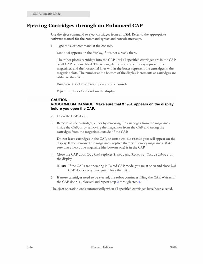
LSM Automatic Mode
3-14 Eleventh Edition 9206
Ejecting Cartridges through an Enhanced CAP
Use the eject command to eject cartridges from an LSM. Refer to the appropriate software manual for the command syntax and console messages.
1. Type the eject command at the console.
Locked appears on the display, if it is not already there.
The robot places cartridges into the CAP until all specified cartridges are in the CAP or all CAP cells are filled. The rectangular boxes on the display represent the magazines, and the horizontal lines within the boxes represent the cartridges in the magazine slots. The number at the bottom of the display increments as cartridges are added to the CAP.
Remove Cartridges appears on the console.
Eject replaces Locked on the display.
CAUTION:ROBOT/MEDIA DAMAGE. Make sure that Eject appears on the display before you open the CAP.
2. Open the CAP door.
3. Remove all the cartridges, either by removing the cartridges from the magazines inside the CAP, or by removing the magazines from the CAP and taking the cartridges from the magazines outside of the CAP.
Do not leave cartridges in the CAP, or Remove Cartridges will appear on the display. If you removed the magazines, replace them with empty magazines. Make sure that at least one magazine (the bottom one) is in the CAP.
4. Close the CAP door. Locked replaces Eject and Remove Cartridges on the display.
Note: If the CAPs are operating in Paired CAP mode, you must open and close both CAP doors every time you unlock the CAP.
5. If more cartridges need to be ejected, the robot continues filling the CAP. Wait until the CAP door is unlocked and repeat step 2 through step 4.
The eject operation ends automatically when all specified cartridges have been ejected.

9206 Eleventh Edition 3-15
LSM Automatic Mode
Ejecting Cartridges through the PCAP
The PCAP is on the enhanced access door. A cartridge is ejected from a PCAP when a message appears on the console to eject the cartridge. Use the eject command to eject cartridges from an LSM. Refer to the appropriate software manual for the command syntax and console messages.
1. Type the eject command at the console.
Locked appears on the display, if it is not already there.
The robot places a cartridge into the CAP.
Remove Cartridge appears on the console.
Eject replaces Locked on the display.
CAUTION:ROBOT/MEDIA DAMAGE. Make sure that Eject appears on the display before you open the CAP.
2. Open the PCAP door.
3. Remove the cartridge from the PCAP slot.
4. Close the PCAP door. Locked replaces Eject and Remove Cartridges on the display.
5. If more cartridges need to be ejected, the robot continues filling the PCAP. Wait until the PCAP door is unlocked and repeat step 2 through step 4.
The eject operation ends automatically when all specified cartridges have been ejected.

LSM Manual Mode
3-16 Eleventh Edition 9206
■ LSM Manual Mode
When the LSM is in manual mode, the robot is disabled, and you must enter the LSM to mount and dismount cartridges in the cartridge drives. Manual operations include:
� Determining when the LSM is not in Automatic Mode� Placing the LSM in Manual Mode� Entering the LSM� Moving the Robot� Removing a Cartridge from 4410 Robot Fingers or Removing a Cartridge from 9310
Robot Fingers� Resetting a Transport/Drive Display� Locating a Cartridge in the LSM� Mounting a Cartridge
Determining when the LSM is not in Automatic Mode
The following conditions indicate when an LSM is not functioning in automatic mode:
� The LSM access door is open.
� The robot does not automatically mount and dismount cartridges.
� A console message informs you that an LSM is not ready, indicating a problem has been detected in the LSM. The message identifies the LSM and provides a code for the failure.
Displaying LSM Status
If you suspect that the LSM is not functioning in automatic mode, type a command at the system console to display the status of the LSM. Refer to the appropriate software manual for the command syntax and console messages. The status display indicates if the LSM is not functioning in automatic mode.
Dual LMU Environment
ACS requests cannot effectively be automated if all stations are offline to the LMU, or if all online station paths are not working. In a dual LMU environment, if all online station paths to the master LMU are not working, use the appropriate switch command to move the work load to the standby LMU.

9206 Eleventh Edition 3-17
LSM Manual Mode
Placing the LSM in Manual Mode
Refer to the appropriate software manual for the command syntax and console messages to place the LSM in manual mode. The LSM remains in manual mode until you issue a command to place the LSM online.
Making Sure the LSM is Offline
If you do not see a console message indicating that the LSM is offline, type a command to display the LSM status.
Note: Placing the LSM offline does not cause the cartridge drives (CDs) in the affected LSM to become offline.

LSM Manual Mode
3-18 Eleventh Edition 9206
Figure 3-6. Standard LSM Access Door—Outside View
CARTRIDGEACCESSPORT (CAP)
ACCESSDOORLATCH
LOCKACCESSDOOR(LAD)
LOCKACCESSDOORLATCH
C29429

9206 Eleventh Edition 3-19
LSM Manual Mode
Figure 3-7. Enhanced LSM Access Door—Outside View
C29399
PRIORITYCARTRIDGEACCESSPORT
ACCESSDOORLATCH
LOCKACCESSDOOR(LAD)
LOCKACCESSDOORLATCH
CARTRIDGEACCESSPORTS
CAPACCESSDOORLATCHES

LSM Manual Mode
3-20 Eleventh Edition 9206
Entering the LSM
WARNING:
To prevent personal injury, follow the steps below:
• Do not enter the LSM until you are thoroughly familiar with this procedure.
• See to Figure 3-6 on page 3-18 or Figure 3-7 on page 3-19 and familiarize yourself with the access door and its components.
• Do not attempt to override any of the electrical or mechanical safety devices in this machine.
• Do not enter the LSM without informing someone in the immediate area.
• Never shut the LSM door when you leave without first making sure that the LSM is unoccupied. Look around the inside of the LSM, and then ask in a loud voice if anyone is inside.
Entrer Dans Le LSM
ATTENTION:
• Ne pas entrer dans le LSM avant d’être parfaitement familiarisé avec cette procédure.
• Se reporter à l'illustration 3-6 et l’illustration 3-7 et se familiariser avec la porte d’accès et ses composants.
• Ne pas tenter de neutraliser les dispositifs de sécurité électriques ou mécaniques de cette machine.
• Ne pas entrer dans le LSM sans en informer une personne à proxim-ité.
• Ne jamais fermer le LSM sans avoir auparavant vérifié que le LSM était vide. Regarder à l’intérieur du LSM puis demander à voix haute si quelqu'un s’y trouve.
9206 Eleventh Edition 3-21
LSM Manual Mode
Betreten des LSM
WARNUNG:
• Das LSM erst betreten, wenn dieses Verfahren genau bekannt ist.
• Abbildung 3-6 bzw. Abbildung 3-7 ansehen, um sich mit der Eingang-stür und ihren Komponenten vertraut zu machen.
• Niemals versuchen, die elektrischen oder mechanischen Sicherheit-seinrichtungen dieser Maschine zu umgehen.
• Das LSM nie betreten, ohne vorher jemanden in unmittelbarer Nähe informiert zu haben.
• Niemals die LSM-Eingangstür schließen, ohne vorher geprüft zu haben, ob das LSM leer ist. Das Innere des LSM absuchen und laut fragen, ob sich noch jemand darin aufhält.
Ingresso nell’LSM
AVVERTENZA:
• Non entrare nell’LSM se non si conosce bene questa procedura.
• Vedere la Figura 3-6 o la Figura 3-7 per acquisire dimestichezza con la porta d’accesso e i suoi componenti.
• Non tentare di ignorare i dispositivi di sicurezza meccanici o elettrici di questa macchina.
• Non entrare nell’LSM senza informarne qualcuno nell’area circos-tante.
• Non chiudere mai la porta dell’LSM quando si esce senza prima veri-ficare che l’LSM non sia occupato. Guardarsi intorno all’interno dell’LSM e quindi chiedere ad alta voce se c’è nessuno.
When you begin the procedure to enter the LSM, the LED warning sign next to the lock access door (LAD) displays the words DO NOT OPEN.
Refer to the appropriate software manual for the command syntax and console messages and do the following:
1. If the LSM is online, place the LSM offline to all hosts. The Do Not Open warning display turns off and the robot stops. This stops all outstanding library requests.
2. Wait for the message that confirms that the LSM is offline. If the LSM does not come offline, enter a command to display the status of the ACS.

LSM Manual Mode
3-22 Eleventh Edition 9206
3. Wait for the outstanding processes to complete or type the command to force the LSM offline to all hosts.
4. Open the lock access door (LAD) and expose the door lock (Figure 3-8). Opening the LAD activates a switch, automatically causing a software interrupt and stopping the robot.
Figure 3-8. LSM Access Door Latch and Door Lock Cover
ACCESSDOORLATCH
LOCKACCESSDOOR(LAD)
1/4TURN
LOCKACCESSDOORLATCH
DOORLOCK
LOCKACCESSDOOR(LAD)
WARNINGLABEL
C29430

9206 Eleventh Edition 3-23
LSM Manual Mode
5. Insert the key and unlock the access door.
6. Pull the paddle handle to activate the opening mechanism and open the access door. At this time, several things happen:
a. The locking pins activate the Door-Seated (ajar) switch.
b. After 2 degrees of door rotation, power to the robot is turned off.
c. Two serial interlock switches are deactivated in the circuit that powers the robot rotation.
d. The Door Has-Been-Opened (HBO) switch is activated, causing an interrupt to software.
e. The Safety Sign switch activates the DO NOT ENTER sign inside the library (Figure 3-9 on page 3-24).

LSM Manual Mode
3-24 Eleventh Edition 9206
Figure 3-9. LSM Warning Light
DO NOT ENTER
EINTRITT VERBOTEN
NE PAS ENTRER
NON ENTRARE
SAFE TO ENTER
EINTRITTERLAUBT
ENTRER
SI PUO ENTRARE
DO NOT ENTER
DETAIL - WARNING LIGHT ASSEMBLY FRONT PANEL
DOORROD
ACCESSDOOR C29431

9206 Eleventh Edition 3-25
LSM Manual Mode
7. Return the key lock to the locked position, remove the key, and close the LAD.
This causes:
� The sign inside the LSM to display Safe to Enter� The lights inside the LSM to turn on � The locking pins to jam outward to prevent anyone from closing the door� The safety switches to activate
8. Put the key in your pocket so that no one can close the door while you are inside; enter the LSM.
In the unlikely event that someone becomes locked inside and the system begins to start up, lights flash for 30 seconds before the robot starts to move. This provides enough time and light to find the door and open it using the interior latch, or to push the emergency power off (EPO) switch next to the interior latch. Either of these actions stops any further power up.
The inside door latch always allows someone to exit, regardless of the position of the exterior key.
WARNING:This system is not foolproof and cannot detect all obstructions.
ATTENTION:Le système n’est pas à l’abri d’un déréglage et ne peut pas détecter tous les types d’obstacles.
WARNUNG:Das System ist nicht narrensicher und kann nicht alle Hindernisse erkennen.
AVVERTENZA:Il sistema non è sicuro al cento per cento e non può rilevare tutte le ostruzioni.
In addition, when the robot is powered on, the theta arm slowly sweeps the interior of the LSM, searching for any obstruction (such as a tool box or oscilloscope). In this mode, current is limited and the theta arm can be stopped by hand.
If any physical obstruction prevents the theta arm from moving for more than a few seconds, the theta arm shuts down and an error is posted. If motion is disturbed only for a moment, the theta arm continues to sweep, but posts an error at the end of initialization, without going into normal move mode.
Note: You may make as many LSM keys as you wish. Record the key number and store it in a safe place. Order copies from Illinois Lock Company (refer to the key package located inside the access door or call 312.537.1800). An experienced locksmith can open the lock.

LSM Manual Mode
3-26 Eleventh Edition 9206
Moving the Robot
You might need to move the robot to make it easier to retrieve cartridges from the LSM and manually load/unload those cartridges into the cartridge drive transports. The amount of movement is dictated by the location of the cartridge in the LSM and the location of the cartridge drive transport into which you are going to load/unload it.
The following pages describe how to rotate, raise, and lower the robot, and how to remove a cartridge from the robot fingers.
WARNING:
To prevent physical injury and damage to components, follow these steps:
• Do not enter the LSM until you are familiar with the procedure described in “Entering the LSM” on page 3-20.
• Do not enter the LSM or move any of its robotics mechanisms if you have any reason to suspect they are enabled.
ATTENTION:
• Ne pas entrer dans le LSM avant d’être familiarisé avec les procé-dures décrites dans le paragraphe « Entrer Dans Le LSM ».
• Ne pas entrer dans le LSM ou ne déplacer aucun des mécanismes de robotique, dans le cas où ces derniers semblent défectueux.
WARNUNG:
• Das LSM erst betreten, wenn das unter “Betreten des LSM” beschrie-bene Verfahren bekannt ist.
• Das LSM nicht betreten und keinen der Robotermechanismen bewe-gen, wenn der Verdacht besteht, daß diese aktiviert sind.
AVVERTENZA:
• Non entrare nell’LSM se non si conosce bene la procedura descritta nella sezione “Ingresso nell’LSM”.
• Non entrare nell’LSM o muovere i meccanismi robotici se si ha motivo di sospettare che siano abilitati.

9206 Eleventh Edition 3-27
LSM Manual Mode
CAUTION:
To prevent damage to robotic components, follow these steps:
• Do not touch any shiny polished surfaces. Body oils can destroy the lubrication on these surfaces.
• Do not touch any lubricated parts.
• Push or pull the robotics carriage only as shown in the following figures.
• The robot should move freely. Do not force the robot if movement is restricted.
Raising and Lowering the Robot
WARNING:ELECTRICAL SHOCK. Using extreme caution, make sure that your hand is placed at a point where no electrical parts are exposed.
ATTENTION:Faire preuve de prudence et s’assurer que les mains ne touchent pas les composants électriques apparents.
WARNUNG:Mit besonderer Vorsicht sicherstellen, daß die Hand nicht an einer Stelle aufliegt, wo stromführende Teile freiliegen.
AVVERTENZA:Facendo particolare attenzione, verificare non vi siano parti elettriche esposte nei punti in cui si appoggiano le mani.
If you need to raise or lower the robot, gently pull down or push up by placing your hand under the Z arm as shown in Figure 3-10 on page 3-28 for the 4410 LSM or Figure 3-11 on page 3-29 for the 9310 LSM.

LSM Manual Mode
3-28 Eleventh Edition 9206
Figure 3-10. Raising and Lowering the 4410 Robot
C29400
Z ARM
PULL DOWNOR PUSHUP HERE
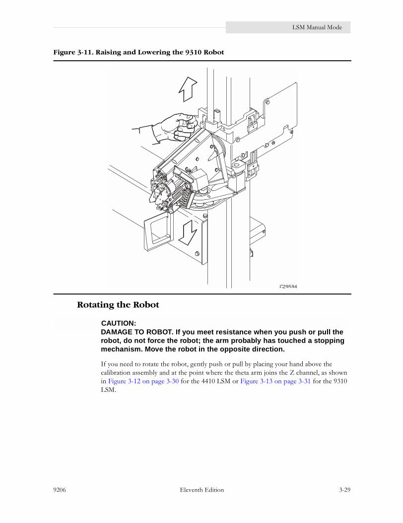
9206 Eleventh Edition 3-29
LSM Manual Mode
Rotating the Robot
CAUTION:DAMAGE TO ROBOT. If you meet resistance when you push or pull the robot, do not force the robot; the arm probably has touched a stopping mechanism. Move the robot in the opposite direction.
If you need to rotate the robot, gently push or pull by placing your hand above the calibration assembly and at the point where the theta arm joins the Z channel, as shown in Figure 3-12 on page 3-30 for the 4410 LSM or Figure 3-13 on page 3-31 for the 9310 LSM.
Figure 3-11. Raising and Lowering the 9310 Robot
C29594

LSM Manual Mode
3-30 Eleventh Edition 9206
Figure 3-12. Rotating the 4410 Robot
C29401
THETAARM
Z CHANNEL
CALIBRATIONASSEMBLY
PUSH ORPULL HERE

9206 Eleventh Edition 3-31
LSM Manual Mode
The restrictions on robot movement described in the following steps apply to the lead screw-driven Z channel machines, due to the design of the theta stop. Check the location of the robot and move the robot as described in the appropriate step.
Figure 3-13. Rotating the 9310 Robot
C29595

LSM Manual Mode
3-32 Eleventh Edition 9206
� If the robot has stopped directly opposite (180 degrees) from the access door, pull the robot from the left side of the LSM (counterclockwise). Do not pass the access door (Figure 3-14).
Figure 3-14. Rotating the 4410 Robot 180 Degrees
STOPHERE
ROBOT
LIBRARYCONTROLUNIT(LCU)
LSMACCESSDOOR
CARTRIDGEACCESSPORT (CAP)
CARTRIDGEDRIVE(CD)
ADDITIONAL
CARTRIDGE
DRIVE
C29432

9206 Eleventh Edition 3-33
LSM Manual Mode
� If the robot has stopped on the left side of the LSM and is less than 180 degrees from the access door, pull the robot from the left side of the LSM (counterclockwise). Do not pass the access door (Figure 3-15).
Figure 3-15. Rotating the 4410 Robot Counterclockwise
ROBOT
ACCESSDOOR
CARTRIDGEACCESSPORT (CAP)
ADDITIONAL
CARTRIDGE
DRIVECARTRIDGEDRIVE(CD)
C29433
LIBRARYCONTROLUNIT(LCU)
STOPHERE

LSM Manual Mode
3-34 Eleventh Edition 9206
� If the robot has stopped on the right side of the LSM and is less than 180 degrees from the access door, pull the robot from the right side of the LSM (clockwise). Do not pass the access door (Figure 3-16). The robot contains a braking assembly that prevents continuous rotation. The allowable range is roughly ± 240 degrees.
Figure 3-16. Rotating the 4410 Robot Clockwise
STOPHERE
LIBRARYCONTROLUNIT(LCU)
ACCESSDOOR
ROBOT
CARTRIDGEACCESSPORT(CAP)
ADDITIONALCARTRIDGE
DRIVE
C29434
CARTRIDGEDRIVE(CD)

9206 Eleventh Edition 3-35
LSM Manual Mode
WARNING:Before you close the LSM access door, look inside the LSM and ask in a loud voice to determine whether anyone is inside the LSM.
ATTENTION:Avant de fermer la porte d’accès du LSM, regarder à l’intérieur puis demander à voix haute si quelqu’un s’y trouve.
WARNUNG:Vor dem Schließen der Eingangstür zum LSM im Innern nachsehen und laut fragen, ob sich noch jemand darin aufhält.
AVVERTENZA:Prima di chiudere la porta d’accesso, guardare all’interno dell’LSM e chiedere ad alta voce se c’è qualcuno.
CAUTION:DAMAGE TO ROBOT. Make sure that the robot is not resting against the mechanical stop.
Make certain that no extra material (manuals, eyeglasses, tools) are left inside. These objects would cause the robot to stop and could damage the robot.

LSM Manual Mode
3-36 Eleventh Edition 9206
Removing a Cartridge from 4410 Robot Fingers
WARNING:Do not enter the LSM until you are familiar with the procedure described in “Entering the LSM” on page 3-20. Do not enter the LSM or move any of its robotics mechanism if you have any reason to suspect it is enabled.
ATTENTION:Ne pas entrer dans le LSM avant d'être familiarisé avec les procédures décrites dans le paragraphe « Entrer Dans Le LSM ». Ne pas entrer dans le LSM ou ne déplacer aucun des mécanismes de robotique, dans le cas où ces derniers semblent défectueux.
WARNUNG:Das LSM erst betreten, wenn das unter “Betreten des LSM” beschriebene Verfahren bekannt ist. Das LSM nicht betreten und keinen der Robotermechanismen bewegen, wenn der Verdacht besteht, daß diese aktiviert sind.
AVVERTENZA:Non entrare nell’LSM se non si conosce bene la procedura descritta nella sezione “Ingresso nell’LSM”. Non entrare nell’LSM o muovere i meccanismi robotici se si ha motivo di sospettare che siano abilitati.
CAUTION:
To prevent damage to robotic components, follow these steps:
• Be extremely careful when you remove a cartridge from the robot fingers (gripper assembly). Perform the following procedure exactly. In particular, do not bend the fingers; use the knob on the stepper motor to release the grip. Failure to do so causes mechanical damage to the finger mechanism.
• Do not touch any shiny polished surfaces. Body oils can destroy the lubrication on these surfaces.
• Do not touch any lubricated parts.
• Do not push or pull the cartridge, fingers, plunger, camera, or any other part of the reach function mechanism except as shown in the following figures.
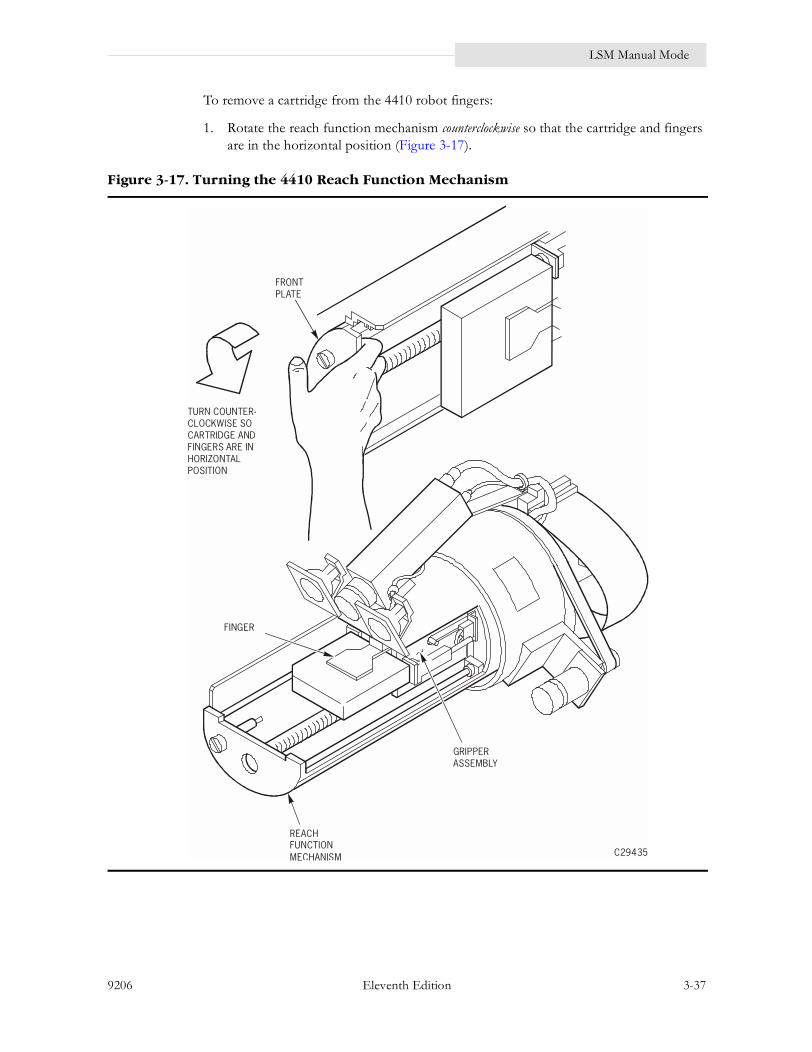
9206 Eleventh Edition 3-37
LSM Manual Mode
To remove a cartridge from the 4410 robot fingers:
1. Rotate the reach function mechanism counterclockwise so that the cartridge and fingers are in the horizontal position (Figure 3-17).
Figure 3-17. Turning the 4410 Reach Function Mechanism
C29435
FRONTPLATE
TURN COUNTER-CLOCKWISE SOCARTRIDGE ANDFINGERS ARE INHORIZONTALPOSITION
FINGER
REACHFUNCTIONMECHANISM
GRIPPERASSEMBLY

LSM Manual Mode
3-38 Eleventh Edition 9206
2. To extend the gripper assembly forward, grasp the cartridge with your left hand and pull gently, until the gripper assembly has extended to its maximum length (Figure 3-18).
3. Grasp the gripper assembly with your right hand, then hold it in the extended position.
4. Grasp the gripper fingers with your left hand and hold that position.
Figure 3-18. Extending the Gripper Assembly
GRIPPERASSEMBLYIN EXTENDEDPOSITION
LEFT HAND ON TAPE,EXTEND GRIPPER:HOLD EXTENDEDWITH RIGHT HANDON GRIPPERMOTOR DIAL
C29436

9206 Eleventh Edition 3-39
LSM Manual Mode
5. Turn the gripper motor dial counterclockwise to release the cartridge from the fingers (Figure 3-19).
6. Remove the cartridge.
Figure 3-19. Turning the Gripper Motor Dial
GRIPPER MOTOR DIAL(TURN COUNTER-CLOCKWISE)
HOLD THE FINGERS WITHTHE LEFT HAND ANDTURN DIAL COUNTER-CLOCKWISE WITH RIGHT HAND.
C29437

LSM Manual Mode
3-40 Eleventh Edition 9206
Removing a Cartridge from 9310 Robot Fingers
CAUTION:EQUIPMENT DAMAGE. Be extremely careful when you remove a cartridge from the robot fingers (gripper assembly). Perform the following procedure exactly to avoid damaging the equipment.
To remove a cartridge from the 9310 robot fingers:
1. Raise or lower the robot by using the wrist stop until the robot is waist high (Figure 3-11 on page 3-29).
2. Extend the gripper by grasping the cartridge and gently pulling until the gripper is fully extended (Figure 3-20 on page 3-41).
3. Gently squeeze the back of the top and bottom fingers until the tension on the cartridge is removed.
4. Remove the cartridge and release the fingers.

9206 Eleventh Edition 3-41
LSM Manual Mode
Figure 3-20. Removing a Cartridge from the 9310 Robot Fingers
C29596

LSM Manual Mode
3-42 Eleventh Edition 9206
Resetting a Transport/Drive Display
Note: Resetting the display is not required for a T9x40 tape drive.
At the beginning of manual mode operation, each 4xxx transport is in a �Hold Off Load� condition. In this condition, the message display panel above the transport is blank and the transport does not load if a cartridge is mounted. You must clear this condition before you can mount cartridges manually.
To reactivate the 4xxx transport display and clear the Hold Off Load condition:
1. If the transport contains an unloaded cartridge, dismount the cartridge and remove it from the LSM.
WARNING:PHYSICAL INJURY: Empty transports perform elevator motions during initialization. Stay clear of the cartridge insertion opening until the display becomes active.
Before you insert a cartridge into a transport in a manual-mode LSM, make sure that either StorageTek, an asterisk, or the volume/cell location information appears on the transport display panel.
ATTENTION:Un mécanisme d’entraînement vide déclenche des mouvements de l’élévateur lors de l’activation. S’éloigner de l’ouverture d’insertion des cartouches jusqu’à ce que le panneau d’affichage soit actif.
Avant d’introduire une cartouche dans le mécanisme d’entraînement en mode manuel, vérifier que StorageTek, un astérisque ou le volume/localisation de la cellule apparaît sur le panneau d’affichage du mécanisme d’entraînement.
WARNUNG:Leere Transportteile führen während der Initialisierung Hebebewegungen aus. Von der Kassetteneinführung fernbleiben, bis die Anzeige aktiviert ist.
Vor dem Einlegen einer Kassette in ein Transportteil eines manuell betriebenen LSM sicherstellen, daß entweder Storage Tek, ein Sternchen oder die Mengen/Zellenort-Daten auf dem Anzeigefeld des Transportteils erscheinen.

9206 Eleventh Edition 3-43
LSM Manual Mode
AVVERTENZA:I trasportatori vuoti effettuano movimenti di elevazione durante i test automatici. Stare lontano dall’apertura di inserimento della cartuccia fino a quando il display non diventa attivo.
Prima di inserire una cartuccia in un trasportatore in un LSM a modalità manuale, accertarsi che sul pannello del display del trasportatore siano visualizzati StorageTek, o un asterisco, o le informazioni relative al volume/cella.
2. When the transport is empty and the READY indicator is lit, hold down the REWIND switch for about 4 seconds (Figure 3-21 on page 3-44). This resets the message display and clears the Hold Off Load condition. Repeat this step for every non-busy transport that does not have an active display.
Note: Allocated transports display the cartridge VOLSER and the cell location. An asterisk appears if the transport is not allocated to a mount request.
Controlling the Transport/Drive Display Intensity
Note: A T9x40 tape drive display has no intensity adjustment.
Use the REWIND and UNLOAD switches to control the intensity of the message display. When you hold down these two switches at the same time, the display dims to the next level of intensity every 2 seconds (100 percent, 50 percent, 25 percent, and off), continuing to cycle until you release the switches. The brightness remains at the level that exists when you release the two switches.
Note: The drive must be in the READY state for these switches to function in this way.
*

LSM Manual Mode
3-44 Eleventh Edition 9206
Figure 3-21. 4xxx CD Message Display and Operator Panels—Inside LSM
R E W I N D
U N L O A D
R E A D Y
SELE
CT
OPER
ATO
R
OFFL
INE
C296
37
CD
MES
SAG
E D
ISPL
AY P
ANEL
S
DD
M C
ARD
DD
CAR
D
CD
CO
NTR
OL
PAN
EL (F
RON
T)
1 3
0 2
SELE
CT
SELE
CT
SELE
CT
SELE
CT
OPE
RATO
R
OPE
RATO
R
OPE
RATO
R
OPE
RATO
R
OFF
LIN
E
OFF
LIN
E
OFF
LIN
E
OFF
LIN
E

9206 Eleventh Edition 3-45
LSM Manual Mode
Locating a Cartridge in the LSM
The cartridge volume serial ID (VOLSER) and cell location are provided in a console message and on the transport/drive display panel.
Cartridge Location in the Console Message
The console message provides the VOLSER and cell location of the cartridge, and the address of the transport/drive allocated for the mount. Before you enter the LSM, write down the VOLSER, cell location, and transport/drive address that is given in the console message.
Figure 3-22 on page 3-46 through Figure 3-27 on page 3-51 show how panels, rows, and columns are numbered. The panel type associated with a particular panel applies only to this example. Panels 1 through 9 may be configured differently in your environment.
Cartridge Location on Message Display Panel
Inside a manual mode LSM, the transport/drive display panel switches back and forth between the VOLSER and cell location of the requested cartridge. The VOLSER appears as seven characters: the six-character volume serial number prefixed with an M, indicating the transport is awaiting the mount.
The cell location appears in the following format:
where:
ll calls out an LSM pp calls out an LSM panelrr calls out a row in the panelcc calls out a column in the row
An example of the location displayed is:
In this example, the cartridge is located in LSM 01, panel 07, row 11, column 15.
l l p p r r c c
0 1 0 7 1 1 1 5

LSM Manual Mode
3-46 Eleventh Edition 9206
Figure 3-22. LSM Wall Numbering
POSSIBLEADDITIONAL
CARTRIDGE DRIVE(MAXIMUM OF 4
CARTRIDGEDRIVES
PER LSM)
CARTRIDGEDRIVE
LCU
LCU
SLAVE
PASS-THRUPORT (PTP)
INNERDOOR
CAP1
2
3
4
13
14
15
6
0
5
7
17
18
8
19
9
12
10
11
16
C29439

9206 Eleventh Edition 3-47
LSM Manual Mode
Figure 3-23. Cartridge Locations—Standard and Drive Wall
0 0 023
3.0"
23 23COLUMNS COLUMNS COLUMNS
0 0 0
1 1 1
2 2 2
3 3 3
4 4 4
5 5 5
6 6 6
7 7 7
8 8 8
9 9 9
10 10 10
11 11 11
12 12 12
13 13 13
14 14 14
ROWS
ROWS
ROWS
171 CELLS 173 CELLS 357 CELLS
DRIVE WALL PANEL(10) (ADJACENT TO
DOOR ONLY)
ADDITIONAL DRIVEWALL PANELS
TYPICAL OUTER WALLPANELS 1-6, 8 AND 9
LEGEND:
WALL PANELCALIBRATIONLOCATION
DIAGNOSTIC
This CLN slot is only available for Compatibility 12 microcode. Otherwise, it is a DG slot.
NOTE:
1
CLEANINGCARTRIDGE
1
NOCARTRIDGE
FREEDIAGNOSTICINTERIMREQUEST
RESERVEDFOR ENG.(NOTAVAILABLEFOR HOST)
PANELLABEL
C29440

LSM Manual Mode
3-48 Eleventh Edition 9206
Figure 3-24. Cartridge Locations—Standard Door and LCU Wall
LEGEND:
WALL PANELCALIBRATIONLOCATION
DIAGNOSTIC
NOCARTRIDGE
FREEDIAGNOSTICINTERIMREQUEST
RESERVEDFOR ENG.(NOTAVAILABLEFOR HOST)
PANEL LABEL
1.0"
3.0"
240 CELLS 319 CELLS
ACCESS DOORPANEL 11
OUTER LCU WALL PANEL 0WITH CALIBRATION AND
POWER I/O PANELS
CARTRIDGEACCESSPORT (CAP)21 CELLS
(ROW 6: COLUMN 0,1 COLUMN 2 COLUMN 3,4,5 COLUMN 6,7,8,9
C29441
- DUMP HANDS- CLEAN CARTRIDGE- DIAGNOSTICS- CAMERA CALIBRATION)
0 023 23COLUMNS COLUMNS
0 0
1 1
2 2
3 3
4 4
5 5
6 6
7 7
8 8
9 9
10 10
11 11
12 12
13 13
14 14
ROWS
ROWS

9206 Eleventh Edition 3-49
LSM Manual Mode
Figure 3-25. Cartridge Locations—PTP/CEM Walls
0 023 23COLUMNS COLUMNS
0 0
1 1
2 2
3 3
4 4
5 5
6 6
7 7
8 8
9 9
10 10
11 11
12 12
13 13
14 14
ROWS
ROWS
333 CELLS 333 CELLS
PASS-THRU SLAVE PANEL(TWO OR MORE LSM)
(OPTIONAL POSITIONS)
PASS-THRU MASTERPANEL (7)
(OPTIONAL POSITIONS)
VIRTUAL PTP WALL = STD
3.0"
LEGEND:
WALL PANELCALIBRATIONLOCATION
DIAGNOSTIC
NOCARTRIDGE
FREEDIAGNOSTICINTERIMREQUEST
RESERVEDFOR ENG.(NOTAVAILABLEFOR HOST)
PANEL LABEL
C29442

LSM Manual Mode
3-50 Eleventh Edition 9206
Figure 3-26. Cartridge Locations—Inner Walls
19 19 190 0 0COLUMNS COLUMNS COLUMNS
0 0 0
1 1 1
2 2 2
3 3 3
4 4 4
5 5 5
6 6 6
7 7 7
8 8 8
9 9 9
10 10 10
11 11 11
12 12 12
13 13 13
14 14 14
ROWS
ROWS
ROWS
3.0"
249 CELLS 256 CELLS 242 CELLS
INNER WALLPANEL 19
TYPICAL INNERWALL PANELS 13-18
INNER DOOR PANEL 12
C29443
LEGEND:
WALL PANELCALIBRATIONLOCATION
DIAGNOSTIC
NOCARTRIDGE
FREEDIAGNOSTICINTERIMREQUEST
RESERVEDFOR ENG.(NOTAVAILABLEFOR HOST)
PANEL LABEL

9206 Eleventh Edition 3-51
LSM Manual Mode
Figure 3-27. Cartridge Locations—Enhanced CAP
C29634
CAP 1
80 CELLS
ENHANCED CAPCARTRIDGE LOCATIONS
(ACSLS 3.0 AND ABOVE, HSC 2.0)
CAP 0
CARTRIDGEPOSITION MAGAZINE
POSITION 00
39
0
39 MAGAZINEPOSITION 3
PRIORITYCARTRIDGEACCESSPORTCAP2(PCAP)
80 CELLS
ENHANCED CAPCARTRIDGE LOCATIONS
(HSC 1.2)
CAP 0
CARTRIDGEPOSITION
MAGAZINEPOSITION 0
40
79
0
39
MAGAZINEPOSITION 3
PRIORITYCARTRIDGEACCESSPORT(PCAP)

LSM Manual Mode
3-52 Eleventh Edition 9206
Figure 3-28. Cartridge Locations—20-Drive Wall
C29821
WALL PANELCALIBRATIONLOCATION
DIAGNOSTIC
T9x40CLEANINGCARTRIDGE
PANEL LABEL
LEGEND:
20-DRIVE CABINET WALLPANELS 0-3
(DG-000 = DRIVE WALL 0)(DG-004 = DRIVE WALL 1)(DG-008 = DRIVE WALL 2)(DG-013 = DRIVE WALL 3)
0 21COLUMNS
0
1
2
3DRIVE
0DRIVE
10DRIVE
1DRIVE
11DRIVE
2DRIVE
12DRIVE
3DRIVE
13DRIVE
4DRIVE
14DRIVE
5DRIVE
15DRIVE
6DRIVE
16DRIVE
7DRIVE
17DRIVE
8DRIVE
18DRIVE
9DRIVE
19
4
5
6
7
8
9
10
11
12
13
14
ROWS
19 CELLS
20-DRIVE CABINET WALLPANELS 0-3

9206 Eleventh Edition 3-53
LSM Manual Mode
Mounting a Cartridge
When the operating system sends a mount request for a volume residing in a manual-mode LSM, the transport/drive display shows the location of the cartridge.
To mount a cartridge:
WARNING:Do not enter the LSM until you are familiar with the procedure described in “Entering the LSM” on page 3-20.
ATTENTION:Ne pas entrer dans le LSM avant d’être familiarisé avec les procédures décrites dans le paragraphe « Entrer Dans Le LSM ».
WARNUNG:Das LSM erst betreten, wenn das unter “Betreten des LSM” beschriebene Verfahren bekannt ist.
AVVERTENZA:Non entrare nell’LSM se non si conosce bene la procedura descritta nella sezione “Ingresso nell’LSM”.
1. Enter the LSM.
2. Write down the VOLSER and cell location of the requested volume, and the address of the assigned transport/drive shown in the message.
3. Reset the transport/drive display if it is not active (see �Resetting a Transport/Drive Display� on page 3-42 for instructions).
4. Locate the cartridge and remove it from the cell location.
5. Inspect the cartridge for damage (see �Inspecting a Cartridge� on page A-4).
WARNING:POSSIBLE PHYSICAL INJURY. Keep your fingers out of the transport when you mount a cartridge; the elevator lowers automatically.
ATTENTION:Lors du montage des cartouches, éloigner les mains du mécanisme d’entraînement; l’élévateur descend automatiquement.
WARNUNG:Beim Montieren einer Kassette nicht mit den Fingern in die Transportteile fassen; die Hebevorrichtung senkt sich automatisch.
AVVERTENZA:Quando si monta una cartuccia, tenere le dita fuori dal trasportatore; l’elevatore si abbassa automaticamente.

LSM Manual Mode
3-54 Eleventh Edition 9206
6. Verify that the transport Ready LED is lit (or that the T9x40 display shows Ready); then insert the cartridge as shown in:
� Figure 3-29 for T9x40 drives� Figure 3-30 on page 3-55 for 4xxx transports
Note: If the 4xxx transport does not load the cartridge, verify that the elevator is down and press the REWIND switch to activate the transport.
Figure 3-29. Inserting a T9x40 Cartridge
C29843

9206 Eleventh Edition 3-55
LSM Manual Mode
Figure 3-30. Inserting a Cartridge into a 4480 Transport
CARTRIDGEDRIVEWALLPANEL
TRANSPORTDISPLAYS
CARTRIDGEDRIVE
CD CONTROLPANEL(INSIDE LSM)
TRANSPORT 1
CUSTOMERLABEL
CUSTOMERLABEL
C29444

LSM Manual Mode
3-56 Eleventh Edition 9206
Dismounting a Cartridge
To dismount a cartridge:
WARNING:Do not enter the LSM until you are familiar with the procedure described in “Entering the LSM” on page 3-20.
ATTENTION:Ne pas entrer dans le LSM avant d’être familiarisé avec les procédures décrites dans le paragraphe « Entrer Dans Le LSM ».
WARNUNG:Das LSM erst betreten, wenn das unter “Betreten des LSM” beschriebene Verfahren bekannt ist.
AVVERTENZA:Non entrare nell’LSM se non si conosce bene la procedura descritta nella sezione “Ingresso nell’LSM”.
For 4xxx transports:
1. Be sure the transport is not in use by the system.
2. Enter the LSM and go to the desired transport.
3. Press the READY switch.
This places the Ready switch in the NOT READY position.
4. Press the UNLOAD switch.
This causes the transport to rewind and unload the cartridge.
5. Remove the cartridge from the transport and the LSM.
6. Store the cartridge outside the LSM.
7. Place the READY switch in the READY position.
The Ready LED comes on when this action occurs. The transport is ready for automated operations.

9206 Eleventh Edition 3-57
LSM Manual Mode
For T9x40 drives:
1. Be sure the transport is not in use by the system.
Note: If you press the UNLOAD switch during a write operation, the drive tries to write the remaining data before the cartridge tape unloads. If the operator panel displays the �UnWr xxxx� (Unwritten Data) message (where xxx = the fault symptom code), the attempt failed and some data remains unwritten on the tape. Refer to the T9940 Tape Drive Operator�s Guide, PN 95989, or the T9840 Tape Drive User�s Reference Manual, PN 95739, for this situation.
2. Press the UNLOAD switch. One of the following conditions occurs:
� After the tape rewinds, the cartridge tape ejects from the drive. Remove the cartridge from the drive.
� The cartridge tape fails to eject after the tape rewinds. Refer to the T9840 Tape Drive User�s Reference Manual or the T9940 Tape Drive Operator�s Guide for this situation.

Returning to Automatic Mode
3-58 Eleventh Edition 9206
■ Returning to Automatic Mode
The following pages describe how to return the LSM to automatic mode.
4xxx Transports
All 4xxx transports must be in a ready condition before you close the LSM access door and place the LSM in automatic mode.
1. Check the READY indicator above the READY switch on the CD operator panel for every transport.
2. If this indicator is lit, do nothing to the corresponding transport.
3. If this indicator is not lit, press the READY switch until indicator turns on.
T9x40 Drives
To verify that the T9x40 drives are ready and online, press the MENU switch on the drive operator panel; the display should now show Online.
If the drive displays Offline, press the SELECT switch once to place it online.
� If the drive message indicates Online, the transition to online completed.
� If the Onl Pend message displays, the online state is pending due to completion of diagnostic tests.
� If other messages appear, consult either the T9840 Tape Drive User�s Reference Manual, PN 95739, or T9940 Tape Drive Operator�s Guide, PN 95989.

9206 Eleventh Edition 3-59
Returning to Automatic Mode
Leaving the LSM
Before you leave the LSM, make sure that no tools or foreign objects are left, and no cartridges are outside the cartridge cells. Make sure that nothing is lying on the top portion (the ledge) of the bottom inner wall. Then:
1. Step outside the LSM.
WARNING:PHYSICAL INJURY. Before you close the LSM access door, look inside the LSM and ask in a loud voice to determine whether anyone is inside the LSM.
ATTENTION:Avant de fermer la porte d’accès du LSM, regarder à l’intérieur puis demander à voix haute si quelqu’un s’y trouve.
WARNUNG:Vor dem Schließen der Eingangstür zum LSM im Innern nachsehen und laut fragen, ob sich noch jemand darin aufhält.
AVVERTENZA:Prima di chiudere la porta d’accesso, guardare all’interno dell’LSM e chiedere ad alta voce se c’è qualcuno.
2. If necessary, close the CAP door.
3. Remove all cartridges from the CAP and store them outside the LSM.
4. Open the LAD, insert the key in the lock, and turn the key to the unlocked position.
CAUTION:EQUIPMENT/MEDIA DAMAGE. Do not slam the door. You could damage the door, or cause cartridges to fall onto the floor. The robot cannot recover cartridges that fall onto the floor.
5. Pull the latch handle and gently close the door, pushing on both the top and the bottom of the door until it clicks shut.
6. Turn the key to the locked position.
7. Remove the key from the lock and close the LAD. The LSM automatically performs a quick initialization procedure.

Returning to Automatic Mode
3-60 Eleventh Edition 9206
Placing the LSM in Automatic Mode
Type the appropriate command at the console to place the LSM online to all hosts. Refer to the appropriate software manual for the command syntax and console messages.
Entering Cartridges Removed During Manual Mode
To return the cartridges to the LSM that you removed while the LSM was in manual mode, do one of the following:
� After you place the LSM online to all hosts, enter the cartridges through the CAP, as described in �Entering Cartridges through Standard CAP�Manual Mode� on page 3-3 or �Entering Cartridges through Enhanced CAP�Manual Mode� on page 3-7.
� Before you leave the LSM, place all cartridges into the storage cells of one panel, and audit that panel.
� Before you leave the LSM, place the cartridges in empty cells at random on several different panels and audit the entire LSM (or at least all panels with added cartridges).

9206 Eleventh Edition 3-61
LMU Operation
■ LMU Operation
The LMU responds to mount and dismount requests from the host through the library software and passes each request to the desired LSM, which performs the physical action requested. The following pages describe your procedures for stand-alone LMU and dual LMU configurations. Emergency power off procedures are the same for both configurations.
See Chapter 2, �Controls and Indicators,� for explanations of LMU control panels. Refer to the appropriate software manual for the command syntax and console messages.
Operating an LMU—Stand-alone Configuration
The following sections describe how to operate a stand-alone LMU.
Powering On/IPLing an LMU
To power on a stand-alone LMU:
� Press the power switch on the LMU operator panel. (On older models, press the switch to the �|� position; the indicator in the switch lights. If it does not, call a service representative to restore power.)
Displaying LMU Status
Type the appropriate command to display LMU status. The command lists:
� Current status of the ACS� Current status of the LMU� Online, offline or standby status of each LMU station
Powering Off an LMU
To power off a stand-alone LMU:
1. Place all stations offline to all software.
Note: Leaving stations online when you power off an LMU causes I/O error messages to appear on the console.
2. Press the power switch on the LMU operator panel. (On older models, press to �0�; the indicator light in the switch turns off).
Note: In a dual LMU environment, powering off the master LMU starts an LMU switch that causes the standby LMU to become the master LMU. See �Operating an LMU�Dual LMU Configuration� on page 3-62 for more information.

LMU Operation
3-62 Eleventh Edition 9206
Operating an LMU—Dual LMU Configuration
The following sections describe how to operate dual LMUs.
Dual LMU Operation Overview
Dual LMU configurations provide a backup LMU that can take over if the active (master) LMU fails. Both LMUs are capable of being the master, but only one can be the master at a given moment. The LMUs regularly check the status of each other over the local area network (LAN).
The software directs all input/output (I/O) to the master LMU. All stations may be placed online to both LMUs when you start the software. The stations to the current master LMU come fully online, and the stations to the current standby LMU come up as standby.
Note: It is recommended that you place two stations online to each LMU from each host. An automatic LMU switch occurs only in response to a failure in the master LMU. Path failures do not start an LMU switch.
The requirements for a fully functional dual LMU configuration are:
� LMU firmware level 2.3 or higher
� Correct operating software level (refer to the appropriate software manual)
� Both LMUs powered on (one serves as the master, and the other as the standby)
� At least one station online to each LMU from each host (online stations to a standby LMU are called standby stations)
If the above conditions are met, an automatic LMU switch can occur if a failure is detected in the master LMU.
You can use the switch command to manually switch the master LMU functionality to the standby LMU. You may give the switch command even if no LMU internal errors are present.
Note: When you enter the switch command, remember that all hosts connected to the dual LMU ACS are affected by a switch of the master LMU functionality. You must restart enter operations after an LMU switch.
Powering On/IPLing an LMU—Dual LMU Configuration
When an LMU is powered on in a dual LMU environment, it places itself in a standby status and then checks for an active master LMU. If an active master LMU exists, the LMU remains available as the standby LMU. If an active master LMU does not exist, the LMU becomes the master LMU.
If both LMUs are powered-on at about the same time, the first to complete IPL assumes the role of master. If you prefer to call out one LMU as the master, power it on first and wait for it to complete IPL before you power-on the second LMU. The following procedure describes this type of dual LMU power on.

9206 Eleventh Edition 3-63
LMU Operation
1. Load the functional diskettes into the top diskette drives for both LMUs. See �Functional Diskettes� on page 3-68 for instructions on loading a functional diskette.
Notes:
a. You must load both LMUs with the same version of LMU firmware.
b. The correct hardware configuration must be on each LMU diskette.
2. Press the power switch on the operator panel of one LMU. (On older models, press the switch to the �|� position; the indicator in the switch turns on. If it does not, call a service representative to restore power.) Upon IPL completion, the MASTER indicator turns on.
3. Power-on the second LMU by repeating step 2 on the operator panel of the second LMU. The MASTER indicator light blinks briefly on the standby LMU as it polls the master LMU to make sure that it is working.
If both LMUs power-on successfully, the console message shows that the dual LMUs are configured, which LMU is master, and that the standby is ready.
Note: If a series of highlighted messages appear, indicating first one LMU, then the other is master, refer to the software manual for dual LMU recovery procedures.
Displaying Dual LMU Status
To determine the status of the dual LMU, enter a command to display the ACS status. The command response lists:
� Current status of the ACS� Current status of the dual LMU configuration� Master LMU� Standby LMU� online, offline or standby status of each dual LMU station� Software/LMU compatibility levels
LMU Switch Overview
The master LMU functionality is switched in these ways:
� The switch is automatic due to a self-detected failure or power supply problem in the master LMU.
� You start the switch operation.
� The IPL switch on the master LMU is pressed.
� The master LMU is powered off.

LMU Operation
3-64 Eleventh Edition 9206
Consequences of an LMU Switch
When an LMU switch occurs, console messages track the changing status of the master and standby LMUs.
When a switch occurs in a dual LMU environment, the software questions the LMUs to determine the current status of each station. The status of each station is kept as online, offline, standby, pending online, pending offline, or pending force offline. Use the command to display the ACS status to determine the status of each station, as well as the status of each LMU.
Performing an Automatic LMU Switch
LMU firmware detects, reports, and reacts to LMU failures as necessary to keep the ACS working. You have no control over the timing of an automatic LMU switch; therefore, some work might be in process within the LMU.
When the standby LMU takes over as master, it notifies the software of its status and sends the LMU ready signal. The software reads the recovery information that is provided by the new master LMU concerning in-transit cartridges within the various LSMs in the ACS.
The firmware:
1. Marks completed the queued requests, reflecting the current locations of in-transit cartridges
2. Sends all incomplete requests to the new master LMU
3. Marks cartridges as errant when requests cannot be completed successfully
Note: You might need to restart enter and eject operations after an LMU switch.
Performing an Operator-started LMU Switch
Before you start an LMU switch while some stations are communicating, decide if the need to switch LMUs is immediate, or if processing can complete before you make the switch. If the need to switch LMUs is not critical, wait until the LSMs are relatively idle.
Start an LMU switch by typing the switch command. The command is routed through the standby LMU to the disconnected master LMU, causing it to IPL. The following sequence of events occurs:
1. The software sends the switch message.
2. The standby LMU becomes the master LMU; the Master indicator turns on.
3. Online LSMs perform a quick initialization.
4. As each LSM becomes ready, the firmware sends a message.
5. If the old master LMU completes IPL successfully, it becomes the standby LMU.

9206 Eleventh Edition 3-65
LMU Operation
If you give the switch command while processing is active, cartridges might be in-transit in various LSMs. Recovery procedures occur automatically as described in �Performing an Automatic LMU Switch� on page 3-64. Upon receiving the LMU ready signal, the software waits for the LSMs to complete a quick initialization and then re-drives the requests building up in the queue.
Powering Off an LMU—Dual LMU Configuration
To power off the master LMU:
1. Place at least one station online to the standby LMU, if necessary. The station is now on standby.
2. Press the power switch on the operator panel of the master LMU. (On older models, press to �0�; the indicator light in the switch turns off.) This starts an LMU switch. Messages appear on the console that indicate the changing status of the LMUs.
3. Make sure that the MASTER indicator turns on as the standby LMU becomes the new master LMU.
A message appears if the standby LMU successfully assumes the role of master LMU.
All LSMs go through quick-init and recovery procedures.
All LMU requests except enter requests are re-driven. You must restart enter operations.
Note: Enter operations end when a master LMU is powered off. Other LMU and robotics operations recover and complete once the standby LMU becomes the new master LMU.
Powering Off the Standby LMU
No special precautions are necessary to power-off the standby LMU; just press the DC power switch on the standby LMU operator panel. Messages appear on the console that indicate which LMU is the master LMU and the changing status of the standby LMU.
Powering Off an LMU—Emergency
To power-off the LMU in an emergency, press the EPO switch on the LMU operator panel. Call a service representative to restore power to an LMU that has been powered down by the EPO switch.

LCU/LSM Operation
3-66 Eleventh Edition 9206
■ LCU/LSM Operation
LANs provide the communication link between the LMU and the LCU. The LCU provides power to the LSM and interprets message commands to the LSM from the LMU. The following sections describe your procedures for the LCU/LSM.
See Chapter 2, �Controls and Indicators,� for explanations of all control panels. Refer to the appropriate software manual for console messages.
Powering On the LCU/LSM
To power on the LCU/LSM, press the power switch on the LCU operator panel. (On older models, press the switch to the �|� position; the indicator in the switch turns on. If it does not, call a service representative to restore power.)
Loading Functional Code—LCU/LSM
The functional code for the LCU is downloaded from the LMU. This code download can only occur when all three conditions exist:
� The LMU is powered up� A functional diskette is in floppy drive 1 of the LMU� The LMU is communicating with the LSM
If the LCU is powered-on, the functional code can be downloaded from the LMU by powering the LCU/LSM off and then on again. Code download and LCU/LSM initialization can take 10 to 25 minutes.
Powering Off the LCU/LSM
To power off the LCU/LSM:
1. Take the LSM offline from all hosts.
Note: Error messages are given if the LCU/LSM are powered off while the LSM is online.
2. Press the power switch on the LCU operator panel. (On older models, press the switch to the �0� position; the indicator in the switch turns off.)
Powering Off the LCU/LSM—Emergency
To power-off the LCU/LSM in an emergency, press the EPO switch on the LCU operator panel. This immediately removes power to the robot and to the LCU.
An EPO switch is also inside the LSM. It is a large red button below the CAP on the panel inside the LSM access door.
Call a service representative to restore power to the LCU/LSM that has been powered off by either EPO switch.

9206 Eleventh Edition 3-67
Cartridge Subsystem Operation
■ Cartridge Subsystem Operation
The procedure for cleaning a transport tape path with a cleaning cartridge is described in �Cleaning the Transport Tape Path.� The procedure for loading a functional diskette is described in �Functional Diskettes� on page 3-68. For other subsystem operations, refer to the appropriate cartridge subsystem operator�s guide.
Cleaning the Transport Tape Path
When a library transport has passed a certain amount of tape media across the read/write heads, it informs the LMU, which broadcasts a �drive needs cleaning� notification to all connected hosts. The software responds to this by either scheduling an automatic cleaning for the transport, or by notifying you with a console message.
Refer to the appropriate software manual for command syntax and console messages. Clean the transport tape path at least once a week even without a message.
To clean the transport tape path:
1. Enter the LSM following the procedures described in �LSM Manual Mode� on page 3-16 for placing the LSM in manual mode, entering the LSM, and resetting the transport displays.
2. Mount a non-library cleaning cartridge in the transport.
3. Dismount the cartridge when it is unloaded.
4. Update the cartridge usage by shading the appropriate number of circles, squares on the label to match the number of cleaning cycles done with that cartridge, if applicable.
Note: Some cleaning cartridges do not have this type of label.
5. Remove the cartridge from the LSM.

Functional Diskettes
3-68 Eleventh Edition 9206
Cleaning Cartridges
Cleaning cartridges have a unique 3-character alphanumeric prefix in their VOLSER (the default is �CLN�). Cartridges with that prefix make up pools of cleaning cartridges in each LSM. Cleaning cartridges cannot be used as scratch cartridges or initialized by software utilities.
CAUTION:READ/WRITE PERFORMANCE DEGRADATION: Do not re-enter a cleaning cartridge that has been ejected from the library. When you enter a cleaning cartridge, the software considers it to be new and sets the usage counter to zero.
When a tape drive/transport requires cleaning, the software selects a cartridge from the pool of cleaning cartridges in the LSM that contains the tape drive/transport (or from the closest LSM that has cleaning cartridges). If no cleaning cartridges exist in the ACS, you are prompted to mount a cleaning cartridge. StorageTek recommends that you have one cleaning cartridge in the ACS for each drive wall.
When a cleaning cartridge is used a defined number of times, it is automatically ejected from the library, and you are notified by a console message. Open the specified CAP, remove the ejected cleaning cartridge, and dispose of it.
■ Functional Diskettes
If a functional diskette is in the diskette drive when an LMU, LCU, or CU is powered-up, the program on the diskette is loaded into memory.
If a functional diskette is not in the diskette drive, insert it (see �Loading a Functional Diskette� on page 3-69).
In a dual LMU environment, the functional diskettes in both LMUs should contain the same level of firmware�Release 2.3 or higher. An error message appears on the console if different levels of firmware are loaded.
Note: While the CU is loading from the functional diskette, the indicator in the IPL switch remains lit, and the 4-character display shows changing alphanumeric characters. When the loading process is complete, the IPL indicator turns off, and the 4-character display becomes blank.
If the loading is unsuccessful, the IPL indicator remains lit, and the 4-character display shows a hexadecimal error code.

9206 Eleventh Edition 3-69
Loading a Functional Diskette
■ Loading a Functional Diskette
The LMU, LCU, or CU you are loading could have a floppy drive or a diskette drive. Use the appropriate instructions:
� �Inserting a Floppy Disk into a Drive�� �Inserting a Diskette into a Disk Drive� on page 3-71
Inserting a Floppy Disk into a Drive
To insert a functional disk into a floppy drive:
1. Make sure that the lever at the entry slot of the drive is rotated as far as it will go counterclockwise.
2. Insert the floppy disk into the drive (Figure 3-31 on page 3-70).
CAUTION:DISKETTE/EQUIPMENT DAMAGE: Do not push against the diske if there is any resistance. Damage might occur to the floppy disk, the drive, or both.
3. Push the floppy disk in until it is completely in the drive.
4. Rotate the lever one-quarter turn clockwise.

Loading a Functional Diskette
3-70 Eleventh Edition 9206
Figure 3-31. Inserting a Functional Disk Into a Floppy Drive
C29448
UNLABELEDSIDE

9206 Eleventh Edition 3-71
Loading a Functional Diskette
Inserting a Diskette into a Disk Drive
To insert a 3-1/2 inch diskette in to a disk drive:
1. Verify that the disk drive is empty.
2. Insert the diskette into the drive with the label side facing left.
CAUTION:DISKETTE/EQUIPMENT DAMAGE: Do not push against the diskette if there is any resistance. Damage might occur to the diskette, the diskette drive, or both.
3. Push the diskette into the drive until the button next to the drive pops out.
Figure 3-32. Inserting a Functional Diskette into a Disk Drive
C29915

Loading a Functional Diskette
3-72 Eleventh Edition 9206
This page intentionally left blank.

9206 Eleventh Edition 4-1
4Obtaining Maintenance Support
This chapter describes what to do if problems occur with the Automated Cartridge System (ACS).
In some cases, you might be able to correct the problem.
� When the problem is caused by cartridge tapes, see Appendix A, �Cartridge Tape Information.�
� When the problem is caused by cartridge subsystems or tape drives, refer to the documentation for that product.
In other cases, you must contact your service representative or the Call Center.
� Most of the time, a fault symptom code (FSC) appears on the LSM operator panel display. Write down the information on the display and give it to either your service representative or the staff at the Call Center.
■ Customer Support Services
The Call Center for Customer Support Services (CSS) is available 24 hours a day, seven days a week, to customers with StorageTek maintenance contracts and to StorageTek employees. You can find additional information about the CSS on StorageTek�s external web site at:
http://www.support.storagetek.com/globalnavigation/support

Customer Initiated Maintenance
4-2 Eleventh Edition 9206
■ Customer Initiated Maintenance
Customer Initiated Maintenance begins with a telephone call from you to the StorageTek CSS. You receive immediate attention from qualified StorageTek personnel, who record problem information and respond with the appropriate level of support.
To contact the CSS about a problem:
1. Use the telephone to call the StorageTek Customer Support Services at:
☎ 1.800.525.0369 (within the United States)
☎ 303.673.4056 (outside the United States)
2. Describe the problem to the call taker. The call taker will ask several questions and will either route your call to or dispatch a service representative.
If you have the following information when placing a service call, the process will be much easier:
■ StorageTek’s Worldwide Offices
You may contact any of StorageTek�s worldwide offices to discuss complete storage, service, and support solutions for your organization. You can find address and telephone number information on StorageTek�s external web site at:
http://www.support.storagetek.com/globalnavigation/support
Account name
Site location number
Contact name
Telephone number
Equipment model number
Device address
Device serial number (if known)
Urgency of problem
Fault Symptom Code (FSC)
Problem description

9206 Eleventh Edition A-1
ACartridge Tape Information
This appendix lists basic requirements for cartridges, and describes how to prepare and maintain cartridges.
■ 3480 and Helical Scan Cartridge Specifications
The LSM uses cartridges that meet the specifications defined in the ANSI publication, American National Standard Magnetic Tape and Cartridge for Information Interchange, ACS X3B5.
3480 and helical scan cartridges must meet these requirements:
� Cartridges- 10.16 x 12.7 x 2.54 cm (4 x 5 x 1 in.)- Integrated thumb wheel for 3480; slide switch for helical scan
� Media- Chromium dioxide for 3480; ferromagnetic for helical scan- 1.27 cm (0.5 in.) wide- 165 m (541 ft) long minimum for 3480; 91 m (299 ft) for helical scan- No beginning of tape/end of tape reflective markers
� Volume serial number (VOLSER) label- Valid characters are A-Z, 0-9, # (crosshatch), or trailing blanks- Leading blanks not allowed
Colored cartridges are approved only if the measured reflection density is greater than 1.20, as obtained with an X-Rite 404G color reflection densitometer. For more information about colored cartridges, contact your StorageTek Marketing representative.
Measurements are:
Bandwidth: ANSI Status T Wideband (380 to 780 nanometers)
Measuring range: Density (0.00-2.50) D
Accuracy: ± 0.02 D
Repeatability: ± 0.01 D
Aperture diameter: 3.4 mm

T9840 Cartridge Specifications
A-2 Eleventh Edition 9206
■ T9840 Cartridge Specifications
Table A-1 shows the specifications for T9840 cartridge tapes.
CAUTION:POSSIBLE DATA LOSS: Servo tracks are written on the tape at the factory. When these tracks are mistakenly erased, the cartridge tape must be discarded. Do not degauss T9840 Tape Drive cartridges.
You can find more information about T9840 cartridge tapes and tape drives on the StorageTek external Web site at:
http://www.storagetek.com/prodserv
Table A-1. T9840 Cartridge Tape Specifications
Characteristics Values
Dimensions 125 x 109 x 25.8 mm(4.92 x 4.29 x 1.00 in.)
Weight 0.26 kg (9.17 oz)
Number of tracks 288
Capacity 20 GB uncompressed
Archival Life 15 to 30 years
Media DurabilityShort lengthLong length
80,000 write/read passes minimum 6,500 write/read passes minimum
Load/Unloads 10,000 minimum
TemperatureOperatingStorage (up to 4 weeks)Storage (archival)Shipping
15° to 32°C (60° to 90°F)-5° to 32°C (23° to 90°F18° to 26°C (65° to 79°F)-23° to 49°C (-10° to 120°F
HumidityOperatingStorage (up to 4 weeks)Storage (archival)Shipping
20 to 80%5 to 80%
40 to 60%5 to 80%

9206 Eleventh Edition A-3
T9940 Cartridge Specifications
■ T9940 Cartridge Specifications
Table A-2 shows the specifications for T9940 cartridge tapes.
CAUTION:POSSIBLE DATA LOSS: Servo tracks are written on the tape at the factory. When these tracks are mistakenly erased, the cartridge tape must be discarded. Do not degauss T9840 Tape Drive cartridges.
You can find more information about T9940 cartridge tapes and tape drives on the StorageTek external Web site at:
http://www.storagetek.com/prodserv
Table A-2. T9940 Cartridge Tape Specifications
Characteristics Values
Dimensions 125 x 109 x 25.4 mm(4.92 x 4.29 x 1.00 in.)
Weight 0.26 kg (9.17 oz)
Number of tracks 288
Capacity 60 GB uncompressed
Archival Life 15 to 30 years
Media DurabilityShort lengthLong length
80,000 write/read passes minimum 167 full life write/read passes minimum
Load/Unloads 10,000 minimum
TemperatureOperatingStorage (up to 4 weeks)Storage (archival)Shipping
15° to 32°C (60° to 90°F)-5° to 32°C (23° to 90°F18° to 26°C (65° to 79°F)-23° to 49°C (-10° to 120°F
HumidityOperatingStorage (up to 4 weeks)Storage (archival)Shipping
20 to 80%5 to 80%
40 to 60%5 to 80%

Preparing Cartridges
A-4 Eleventh Edition 9206
■ Preparing Cartridges
The following sections describe how to handle and inspect a cartridge, apply labels, and set the file protect selector or write protect switch.
Handling a Cartridge
Improper handling of cartridges can result in a loss of data or damage to a machine component.
To handle a cartridge correctly:
� Do not carry several cartridges loosely in a container. The leader blocks can snag on other cartridges and become unlatched.
� Make sure that the leader block is latched every time you pick up a cartridge.
� Keep cartridges clean.
� Inspect a cartridge before each use and never put a damaged cartridge into a drive or LSM.
� Never release a leader block and pull tape from a cartridge.
� Never open a cartridge.
� Do not handle tape that is outside the cartridge; the tape edge might be damaged.
� Do not expose the tape or cartridge to direct sunlight or moisture.
� Do not expose a recorded cartridge to magnetic fields; this destroys data on the tape.
Inspecting a Cartridge
A defective or dirty cartridge can damage a transport. Always inspect a cartridge before you enter it into an LSM. See Figure A-1 on page A-5 through Figure A-4 on page A-7. Look for:
� Cracked or broken cartridge� Broken leader block� Broken leader block latch� Damaged file-protect selector� Liquid in the cartridge� Labels not firmly attached or extending over the cartridge edge� Any other obvious damage

9206 Eleventh Edition A-5
Preparing Cartridges
Figure A-1. Inspecting a 3480-type Cartridge
Figure A-2. Inspecting a Helical Scan Cartridge
LEADERBLOCK
FILEPROTECTSELECTOR
LABELS
C29445
C29660
WRITE-PROTECTSWITCH
LABELS
LEADERBLOCK
DETENTSPRINGS

Preparing Cartridges
A-6 Eleventh Edition 9206
Figure A-3. Inspecting a T9840 Cartridge
C29845
CUSTOMERLABEL
ACCESSDOOR
WRITE-PROTECTSWITCH
VOLUMELABELAND MEDIATYPELABELS(MEDIA: “R”=DATA, “U”=CLEANING)

9206 Eleventh Edition A-7
Preparing Cartridges
Figure A-4. Inspecting a T9940 Cartridge
C29838
CUSTOMER AND MANUFACTURER'SLABEL
WRITE-PROTECT SWITCH
LEADER BLOCK - CLOSED
VOLID AND MEDIA LABELS (MEDIA LABEL: "P" = DATA, "W" = CLEANING)
LEADER BLOCK - OPEN

Preparing Cartridges
A-8 Eleventh Edition 9206
Applying Labels to Cartridges
Cartridge labels reflect the cartridge media and usage. Cleaning cartridges have CLN in the volume serial ID (VOLSER); diagnostic cartridges have DG in the VOLSER. The media ID label correlates to the tape drive or transport capable of using the cartridge:
� A, B, and C labels are used for recording in the SD-3.
� D labeled cartridges are used in the SD-3 for cleaning.
� E labeled cartridges can be used for recording in the 4490 and 9490.
� P labeled cartridges are used for recording in the T9940.
� R labeled cartridges are used for recording in the T9840.
� U labeled cartridges are used in the T9840 for cleaning.
� W labeled cartridges are used in the T9940 for cleaning.
� Z labeled cartridges can be used for recording in the 9490.
The kinds of cartridge labels you might need to apply are:
� Customer� VOLSER� Extended media (enhanced tape)
See to Figure A-5 on page A-9 through Figure A-8 on page A-11 to place the labels on the recessed areas on each cartridge:
1. Make sure that the cartridge has been at room temperature at least 24 hours.
2. Clean the surface where you will place the labels with a cleaning solution made for this purpose. See �Cleaning the Cartridge Exterior� on page A-18.
3. Peel the backing from the VOLSER label.
4. Hold the cartridge so that the leader block is above the file protect selector and is facing away from you.
5. Position the label with the VOLSER characters to the left, so you can read them from top to bottom. Press the label into place.
6. If you are using an extended media (enhanced tape) cartridge, peel the backing from the �E� label and place the label in the recessed area to the left of the VOLSER. Press the label into place.
7. If the cartridge has no customer label, place the label in the area shown in Figure A-5 on page A-9 through Figure A-8 on page A-11 and press the label into place.
The labels must be within the indented area of the cartridge so that the edges of the label are parallel to the edges of the cartridge. The label should be close to the inside edge of the indented area but must never overlap the edge of this area.

9206 Eleventh Edition A-9
Preparing Cartridges
Notes:
1. Make sure that labels are not placed elsewhere on the cartridge surface.
2. Make sure that the edges of the labels do not curl up; curling causes the cartridge to stick in the drive loader.
3. Use labels that do not leave a residue when they are removed.
4. Make sure that the label contains a volume serial ID (VOLSER).
Figure A-5. Applying Labels to 3480-type Cartridges
CUSTOMERLABEL
VOLSERLABEL C29446

Preparing Cartridges
A-10 Eleventh Edition 9206
Figure A-6. Applying Labels to Helical Scan Cartridges
C29658
WRITE PROTECTSWITCH
CUSTOMERLABEL
TAPELENGTHLABEL
VOLUME/SERIAL NUMBER(VOLSER)LABEL

9206 Eleventh Edition A-11
Preparing Cartridges
Figure A-7. Applying Labels to a T9840 Cartridge
Figure A-8. Applying Labels to a T9940 Cartridge
C29839
CUSTOMERLABEL
VOLUME(VOLSER) LABEL
MEDIA ID LABEL(”R’=DATA, “U”=CLEANING)
C29840
CUSTOMERLABEL
VOLUME (VOLSER) LABEL
MEDIA ID LABEL ("P" = DATA, "W" = CLEANING)

Preparing Cartridges
A-12 Eleventh Edition 9206
Setting a 3480-type File Protect Selector to Read-Only
You can set the file protect selector so that the cartridge is read-only (nothing can be written on the tape). Turn the thumb wheel on the side of the cartridge until the white dot or white padlock icon on a dark background appears on the wheel (Figure A-9). In this position, the transport can only read data from the tape and cannot write data.
Setting a 3480-type File Protect Selector to Read/Write
You can set the file protect selector so that the cartridge is write-enabled. Turn the thumb wheel on the side of the cartridge until the white dot or white padlock icon above the wheel disappears (Figure A-9). In this position, the transport can write as well as read data. This setting is recommended when you enter cartridges into the LSM.
Note: Some software has a feature called �virtual thumb wheel� that allows read-only access to a cartridge that is not physically write-protected.
Figure A-9. Setting the 3480-type File Protect Sensor
FILEPROTECTEDPOSITION
UNPROTECTEDPOSITION
C29447

9206 Eleventh Edition A-13
Preparing Cartridges
Setting a Helical Scan Write Protect Switch to Read-Only
You can set the write protect switch so that the cartridge is read-only (nothing can be written on the tape). Slide the switch to the right so that the pencil icon is split (Figure A-10). In this position, the drive can only read data from the tape and cannot write data.
Setting a Helical Scan Write Protect Switch to Read/Write
You can set the write protect switch so that the cartridge is write-enabled. Slide the switch to the left so that the pencil icon is joined (Figure A-10). In this position, the drive can write as well as read data. This setting is recommended when you enter cartridges into the LSM.
Note: Some software has a feature called �virtual thumb wheel� that allows read-only access to a cartridge that is not physically write-protected.
Figure A-10. Setting the Helical Scan Write Protect Switch
C29659
LABELS
LEADERBLOCK
WRITE ENABLE POSITION
WRITE PROTECT POSITION
DETENTSPRINGS

Preparing Cartridges
A-14 Eleventh Edition 9206
Setting a T9840 Write Protect Switch to Read-Only
You can set the T9840 write protect switch so that the cartridge is read-only (nothing can be written on the tape). Slide the switch right to the write protect position (Figure A-11). In this position, the drive can only read data from the tape and cannot write data.
Setting a T9840 Write Protect Switch to Read/Write
You can set the T9840 write protect switch so that the cartridge is write-enabled. Slide the switch left to the write enable position (Figure A-11). In this position, the drive can write as well as read data. This setting is recommended when you enter cartridges into the LSM.
Note: Some software has a feature called �virtual thumb wheel� that allows read-only access to a cartridge that is not physically write protected.
Figure A-11. Setting the T9840 Cartridge Write Protect Switch
C29841
WRITEENABLE
POSITION
WRITEPROTECTPOSITION

9206 Eleventh Edition A-15
Preparing Cartridges
Setting T9940 Write Protect Switch to Read-Only
You can set the T9940 write protect switch so that the cartridge is read-only (nothing can be written on the tape). Slide the switch left to the write protect position (Figure A-12). In this position, the drive can only read data from the tape and cannot write data.
Setting T9940 Write Protect Switch to Read/Write
You can set the T9940 write protect switch so that the cartridge is write-enabled. Slide the switch right to the write enabled position (Figure A-12). In this position, the drive can write as well as read data. This setting is recommended when you enter cartridges into the LSM.
Note: Some software has a feature called �virtual thumb wheel� that allows read-only access to a cartridge that is not physically write-protected.
Figure A-12. Setting the T9940 Cartridge Write Protect Switch
C29842
WRITE PROTECT SWITCH
WRITE ENABLED POSITION
WRITE PROTECT POSITION

Maintaining Cartridges
A-16 Eleventh Edition 9206
■ Maintaining Cartridges
The following sections list environmental specifications and describe how to store and clean cartridges, use cleaning cartridges, and repair a detached leader block.
3480-type Cartridge Environmental Specifications
The following specifications refer to the operating and storage environments for 3480-type cartridges:
Operating environment:
Cartridge storage environment:
Helical Scan Cartridge Environmental Specifications
The following specifications refer to the operating and storage environments for helical scan cartridges:
Operating environment:
Cartridge storage environment:
Temperature 15.6º to 32.2ºC (60º to 90ºF)
Relative humidity 20% to 80%
Wet bulb temperature 25.6ºC (78ºF) maximum
Temperature 4.4ºto 32.2ºC (40ºto 90ºF)
Relative humidity 5% to 89%
Wet bulb temperature 26.7º C (80ºF) maximum
Temperature 15º to 27ºC (59º to 81ºF)
Relative humidity 30% to 60%
Wet bulb temperature 25ºC (77ºF) maximum
Temperature 5º to 32ºC (41º to 90ºF)
Relative humidity 5% to 80%
Wet bulb temperature 26ºC (80ºF) maximum

9206 Eleventh Edition A-17
Maintaining Cartridges
T9x40 Cartridge Environmental Specifications
The following specifications refer to the operating and storage environments for T9x40 cartridges:
Operating environment:
Cartridge storage (non-archive) environment:
Cartridge storage (archive) environment:
Storing Cartridges
When you store a cartridge:
� Do not take a cartridge out of its protective wrapping until you are ready to use it. Use the tear string, not a sharp instrument, to remove the wrapping.
� Store cartridges in a clean environment that duplicates the conditions of the room in which they are used.
� Before you use a cartridge, make sure that it has been in its operating environment at least 24 hours.
Temperature 15.6º to 32.2ºC (60º to 90ºF)
Relative humidity 20% to 80%
Wet bulb temperature 26ºC (78.8ºF) maximum
Temperature 5º to 32.2ºC (41º to 90ºF)
Relative humidity 5% to 80%
Wet bulb temperature 26ºC (78ºF) maximum
Temperature 5º to 25.5ºC (41º to 78ºF)
Relative humidity 40% to 60%
Wet bulb temperature 26ºC (78ºF) maximum

Maintaining Cartridges
A-18 Eleventh Edition 9206
Cleaning the Cartridge Exterior
CAUTION:CARTRIDGE DAMAGE. Certain solvents can damage the cartridges. DO NOT USE ACETONE, TRICHLOROETHANE, TOLUENE, XYLENE, BENZENE, KETONE, METHYL ETHYL KETONE, METHYLENE CHLORIDE, ETHYLDICHLORIDE, ESTERS, ETHYL ACETATE, OR SIMILAR CHEMICALS TO REMOVE LABELS OR TO CLEAN CARTRIDGES.
Wipe all dust, dirt, and moisture from the cartridge with a lint-free cloth.
Use StorageTek Tape Cleaner Wipes, PN 404628901, to clean the cartridges. These wipes are saturated with isopropyl alcohol. Do not let any solution touch the tape or get inside the cartridge.
Using Cleaning Cartridges
Cleaning cartridges have a VOLSER prefix of DG CLN or CLNxxx. These cartridges cannot be used as scratch cartridges nor initialized by software utilities.
CAUTION:PROCEDURE ERROR. When you enter a cleaning cartridge, the software considers it to be new, and sets the usage counter to zero. DO NOT RE-ENTER A CLEANING CARTRIDGE THAT AN LSM HAS EJECTED.
Repairing a Detached Leader Block
When a tape is damaged, use a backup tape. If a single-reel cartridge leader block is detached, the cartridge or tape has no obvious damage, and you have no backup tape, you may repair the leader block using a repair kit provided by your supplier. You can use the tape one time to copy the data onto another tape.

9206 Eleventh Edition Glossary-1
Glossary
This glossary defines terms and abbreviations in this publication.
Some of the definitions are taken from the IBM Dictionary of Computing. The letters in the parentheses that follow some definitions indicate the source of the definition:
(A) The American National Standard Dictionary for Information Systems, ANSI X3.172-1990, copyright 1990 by the American National Standards Institute (ANSI).
(E) The ANSI/Electronic Industries Association (EIA) Standard-440-A, Fiber Optic Terminology.
(I) The Information Technology Vocabulary, developed by Subcommittee 1, Joint Technical Committee 1, of the International Organization for Standardization and International Electrotechnical Commission (ISO/IEC/JTC1/SC1).
(IBM) The IBM Dictionary of Computing, copyright 1994 by IBM.
(T) Draft international standards committee drafts, and working papers being developed by the ISO/IEC/JTC1/SC1.
Numerics
20-drive frame Also known as a 9741/9741E, a drive cabinet that holds up to 20 tape drives (T9840 or T9940).
9741 A drive cabinet that contains up to 20 T9x40 tape drives. (Requires Feature 99DR for T9940 drives.(
9840 See T9840.
9741E A drive cabinet that attaches to the LSM. It holds up to 20 T9x40 tape drives.
9490 A cartridge subsystem that holds two to four TimberLine 9490 cartridge drives and control units.
A
AC Alternating current.
ACS See automated cartridge system.
automated cartridge system (ACS) A system that consists of five components: host software, a library management unit, a library control unit, library storage modules and cartridge subsystems.
These components provide automatic mounting and dismounting of cartridge tapes into a transport, tape drive, cartridge access port, or cartridge exchange mechanism.
automatic mode A relationship between an LSM and all attached hosts. LSMs operating in automatic mode handle cartridges without operator intervention. This is the normal operating mode of an LSM that has been placed online to all host CPUs.
B
beginning-of-tape (BOT) The location on a tape where written data begins.
C
CAP See cartridge access port.
cartridge access port (CAP) A device in the library that allows an operator to insert or remove cartridges during library operations.
cartridge drive (CD) The unit that houses the magnetic-tape transports and controllers that store and retrieve data for the host system in a cartridge subsystem.

Glossary-2 Eleventh Edition 9206
Glossary
cartridge exchange mechanism (CEM) A mechanism that allows a cartridge to pass from one library storage module (LSM) to another in a multiple LSM automated cartridge system. See also pass-thru port.
cartridge subsystem One or more control units, cartridge drives, and controller transports that operate together as a data storage and retrieval subsystem as commanded by the host system to which it is attached.
CD See cartridge drive.
cell A slot in the LSM in which a cartridge is stored.
Central Support Remote Center (CSRC) The remote diagnostic center at StorageTek. CSRC operators can access and test StorageTek systems and software, through telecommunications lines, from remote customer installations. Previously referred to as the Remote Diagnostic Center (RDC).
channel A general term for a path on which signals travel. Synonymous with bus, interface, and I/O.
channel command An instruction that directs a data channel, control unit, or device to perform an operation or set of operations. (IBM)
connected mode A relationship between a host and an ACS. In this mode, the host and an ACS can communicate (at least one station to this ACS is online).
control unit (CU) A device that contains the functional logic to control the input and output operations at one or more devices.
controlling software An ACS component that interfaces between the operating system and the rest of the automated library.
cross-host recovery The ability for one host to perform recovery for another host that has failed.
CSE Customer services engineer.
CSRC See Central Support Remote Center.
CU See control unit.
D
data cartridge A term used to distinguish a cartridge onto which a tape drive may write data from a cartridge used for cleaning or diagnostic purposes.
DC Direct current.
device number A four-digit hexadecimal number that uniquely identifies a device attached to a processor.
diagnostic cartridge A data cartridge with a �DG� label, which is used for diagnostic routines.
disconnected mode A relationship between a host and a library. In this mode, the host and a library cannot communicate (online stations do not exist to this library).
dismount To remove a cartridge from a drive.
drive A device that moves magnetic tape and includes the mechanisms for reading and writing data on the tape.
dual LMU A hardware/software feature that provides a redundant library management unit capability.
E
eject The library robot places a cartridge in a cartridge access port (CAP) so that the operator can remove it.
emergency power off (EPO) A safety scheme that allows a �power down� of a subsystem or a system as a whole instead of powering it down component-by-component.
EOT The location on a tape where written data ends.
EPO See emergency power off.

9206 Eleventh Edition Glossary-3
Glossary
F
file-protect To prevent the destruction or overwriting of data stored on a cartridge tape. See also write-protect.
firmware An ordered set of instructions and data stored in a way that is functionally independent of main storage; for example, microprograms stored in a ROM.
H
hand assembly A part of the library robot whose function is to grasp cartridges and move them between storage cells and drives. A camera on the hand assembly reads cartridge volume labels.
home location The cell in a library storage module (LSM) in which a cartridge is stored. A cartridge returns to this location when it dismounts from a drive or cartridge tape unit.
host The primary computer on a network, with which other computers interacts.
I
ID Identifier or identification.
initial program load (IPL) A process that activates a machine reset and loads system programs to prepare a computer system for operation. Processors having diagnostic programs activate these programs at IPL execution. Devices running microcode software usually reload the functional microcode software from a diskette or disk drive at IPL execution.
input/output (I/O) The process of moving data between a host and an external device. I/O is a collective term for commands, reading, and writing.
insert The action of placing a cartridge into the cartridge access port magazine.
interlock switch A switch that disconnects power to the library when the front door is opened.
intervention required Operator action is required (such as removing a cartridge from a drive).
in-transit cartridge A cartridge left in the robot hand. The Data Management Software must recover this cartridge to a known location to clear out the software in-transit record.
in-transit record A temporary record written by the host software, noting that a cartridge has been moved from its home cell. After this cartridge return to its home cell, the record erases.
IPL See initial program load.
L
LAD See lock access door.
LAN See local area network.
latches The sliding bolts, turned by a key, that secure a library door.
LCU See library control unit.
leader block The mechanism that loads the tape through the tape path of a drive.
LED See light emitting diode.
library An installation of one or more ACSs, attached cartridge drives, volumes placed into the ACSs, host software that controls and manages the ACSs and associated volumes, and the library control data set that describes the state of the ACSs.
library control unit (LCU) The portion of the LSM that controls the choosing, mounting, dismounting, and replacing of cartridges.
library management unit (LMU) The portion of the ACS that controls the library storage module and communicates with the host.

Glossary-4 Eleventh Edition 9206
Glossary
library storage module (LSM) TA housing that contains cartridge tapes and a robot that moves the tapes between storage cells and the attached transports. Synonymous with tape library.
light emitting diode (LED) A light-emitting electronic device that uses little energy and is used mainly on status panels to indicate an on or off condition.
LMU See library management unit.
local area network (LAN) A computer network located on a user�s premises within a limited geographical area. Communication within a local area network is not subject to external regulations; however, communication across the LAN boundary may be subject to some form of regulation. (T)
lock access door A door mounted on the access door for safety reasons. The procedure to open and close the LAD prevents a person from being in the library storage module when the robot is moving.
LSM See library storage module.
LSM number A method used to identify an LSM. The first LSM listed in this parameter is 0 (hexadecimal), the second LSM listed is 1, and so forth, until all LSMs are identified (maximum number of 15 or hexadecimal F).
M
magazine A removable container that holds cartridges and is placed in the cartridge access port (CAP).
maintenance facility Hardware that enables service personnel to run diagnostics, retrieve status, and communicate with these units through their respective control panels.
manual mode A relationship between an LSM and all attached hosts. LSMs operating in manual mode have been placed offline to all host CPUs
and require human assistance to perform cartridge operations.
master LMU The LMU currently controlling the functional work of the ACS in a dual LMU configuration.
modem Modulator/demodulator. An electronic device that converts computer digital data to analog data for transmission over a telecommunications line (telephone line). At the receiving end, the modem performs the inverse function.
monitor A device that observes, records, and verifies the operations of a system to indicate any significant departure from expected operation.
mount To place a cartridge tape in a drive or transport and make it accessible to the host system.
N
not ready Not available to perform operator-requested actions. Some status information might be available through network interfaces.
O
offline Neither controlled by, nor communicating with, a computer. Contrast with online. (IBM)
online Pertaining to the operation of a functional unit when under the direct control of the computer. (T)
operating system (OS) Software that controls the execution of programs and that may provide services such as resource allocation, scheduling, input/output control and data management.
operator control panel A panel that enables users to configure, diagnose, or receive status information about the library or drive. Synonymous with operator panel.
9206 Eleventh Edition Glossary-5
Glossary
P
pass-thru port (PTP) A mechanism that enables a cartridge to pass from one LSM to another in a multiple LSM ACS. See also cartridge exchange mechanism.
PCAP See priority cartridge access port.
priority cartridge access port An assembly that allows an operator to enter or eject one cartridge during automated operations. The PCAP is located on the 80-cell CAP access door of an LSM.
PTP See pass-thru port.
R
read/write head The data sensing and recording unit of a diskette drive or tape drive (IBM)
ready State in which the library is powered on and has completed its initialization and initial program load (IPL). It is ready to accept user requests.
recoverable error An error condition that can be automatically corrected (for example, by initiating a retry operation) and, when corrected, allows continual processing of a job, program, or hardware function.
robot An electromechanical device for locating and moving cartridges.
S
safety interlock switch A switch that disconnects power to the library when the front door is opened.
SD-3 A high-performance information storage and retrieval system that reads and writes in helical-scan format.
software All or part of the programs, procedures, rules, and associated documentation of a data processing system.
standby The status of a station that has been placed online but is connected to the standby LMU of a dual LMU ACS.
standby LMU The redundant LMU in a dual LMU configuration that is ready to take over functions if a master LMU fails or when the operator issues the Switch command.
station A hardware path between the host computer and an LMU over which the controlling software and LMU send control information.
switchover The action of the standby LMU becoming the master LMU.
T
T9840 A cartridge drive that reads/writes to tapes; the housing for the tape contains supply and take-up reels.
T9940 A cartridge drive that reads/writes to tapes; the housing for the tape contains a single reel.
T9x40 Used to indicate either T9840 or T9940 when either or both types of drives are being referred to.
tape drive A device that moves magnetic tape and includes mechanisms for reading and writing data on the tape.
tape library Synonym for library storage module.
transport An electromechanical device capable of threading tape from a cartridge, moving the tape across a read/write head, and writing data onto or reading data from the tape.
U
unrecoverable error An error condition that cannot be automatically corrected and requires an external operation for possible correction. An unrecoverable error causes termination of a job, program, or hardware function.

Glossary-6 Eleventh Edition 9206
Glossary
utilities Utility programs. The programs that allow an operator to manage library resources and to monitor overall library performance.
V
VOLSER Volume serial number. A six-character alphanumeric label used to identify a volume.
volume A data carrier mounts or dismounts as a unit; for example a reel of magnetic tape or a disk pack.
W
write-enabled A setting on a cartridge that allows data to be written on the tape.
write-protected A setting on cartridge tapes that prevents data from being written on the tape. Reading data is still possible.
write tape mark (WTM) An operation that records a special magnetic mark on tape to identify a particular location.

9206 Eleventh Edition Index-1
Index
Numerics
20-Drive Wall, illustrated, 3-523480-type cartridge
file protect selector, A-5labels, A-5leader block, A-5
9490 (TimberLine)3480-type file protect selector, A-12applying cartridge labels, A-9cartridge environment, A-16inspecting a cartridge, A-5operator panel, 2-26overview, 1-7
9741. See 20-Drive Wall9840. See T9840
A
about this guide, xiiiaccess door
ordering replacement keys, 3-25overview, 1-7
ACScomponents, 1-2operating procedures list, 3-1safety features, 1-11
alert messages in manual, xivapplying cartridge labels
3480-type, A-9helical scan, A-10T9840, A-6T9940, A-7
automated cartridge system. See ACSautomatic mode, 3-2
determining state, 3-16overview, 1-10placing the LSM in, 3-60reentering cartridges removed during manual
mode, 3-60returning the LSM to, 3-58
C
CAPenhanced
display panel, 2-13ejecting cartridges, 3-14entering cartridges, 3-7indicators, 2-13
entering cartridges, 3-2overview, 1-7standard
control panel, 2-11ejecting cartridges, 3-13entering cartridges, 3-3indicators, 2-11
cartridge3480 & helical scan
cartridge requirements, A-1colored cartridge specifications, A-1
3480-type environment, A-163480-type file protect selector, A-12cleaning, 3-68dismounting, 3-56ejecting
through enhanced CAP, 3-14through PCAP, 3-15through standard CAP, 3-13
enteringthrough CAP, 3-2through enhanced CAP, 3-7through PCAP, 3-11through standard CAP, 3-3
exterior cleaning, A-18handling, A-4helical scan
environmental specifications, A-16write protect switch, A-13
inspecting, A-4labels
3480-type, A-9extended media (enhanced tape), A-9helical scan, A-10T9840, A-6T9940, A-7

Index-2 Eleventh Edition 9206
Index
locating a cartridge in LSM, 3-45location on transport display panel, 3-45mounting, 3-53reentering, 3-60removing
from 4410 robot fingers, 3-36from 9310 robot fingers, 3-40
repairing detached leader block, A-18storing, A-17subsystem operation, 3-67T9840
labeling, A-11specifications, A-2write protect switch, A-14
T9940labeling, A-11specifications, A-3write protect switch, A-15
using cleaning cartridges, A-18cartridge drive. See CDcartridge exchange mechanism. See CEMcartridge subsystem
cleaning transport tape path, 3-67controls and indicators, 2-19operation, 3-67
cautionmessages in manual, xivshielded cables, xxi
cautionsCAP
CAP LOCKED indicator, 3-3EJECT on display, 3-14ENTER on display, 3-7leaving cells empty, 3-6slamming door, 3-6
lubrication, 3-27moving robot
leaving objects inside, 3-35mechanical stop, 3-35position, 3-27stopping mechanism, 3-29
PCAP, 3-12reentering cleaning cartridge, A-18removing cartridge from robot fingers, 3-36slamming access door, 3-59solvents for cleaning a cartridge, A-18
CDdisplay panel inside LSM, 2-22location, 1-2operator panel
inside LSM, 2-22outside LSM, 2-20
overview, 1-7resetting transport display, 3-42
CEM, passing a cartridge to another LSM, 1-6check code messages, 2-26cleaning cartridge
description, 3-68label, A-18
cleaning exterior of cartridges, A-17cleaning the transport tape path, 3-67colored cartridges, 3480 & helical scan
specifications, A-1compliance statements
FCC, xxiJapanese, xxiiTaiwan, xxii
components, ACS system overview, 1-2connected mode, 1-9contacting StorageTek, 4-2control unit. See CUcontrols and indicators
cartridge subsystem, 2-19CD display panel, 2-22CD operator panel (inside LSM), 2-22CD operator panel (outside LSM), 2-20enhanced CAP display panel, 2-13EPO switch (inside LSM), 2-16LCU/LSM operator panel, 2-5LMU operator panel, 2-1standard CAP control panel, 2-11transport display intensity, 3-43
CUIPLing, 3-68overview, 1-7
Customer Initiated Maintenance (CIM), 4-2customer label
3480-type cartridges, A-9helical scan cartridges, A-10T9840 cartridge, A-6T9940 cartridge, A-7
Customer Support Services (CSS), 4-1

9206 Eleventh Edition Index-3
Index
D
dimensionsT9840 cartridge, A-2T9940 cartridge, A-3
disconnected mode, 1-9diskette, functional (loading), 3-68dismounting a cartridge
4xxx drive, 3-56T9x40, 3-57
displaying LMU statusdual LMU configuration, 3-63stand-alone configuration, 3-61
displaying LSM status, 3-16door (access)
ordering keys, 3-25overview, 1-7
dual LMU. See LMU, dual
E
ejecting cartridges from LSMthrough enhanced CAP, 3-14through PCAP, 3-15through standard CAP in manual mode, 3-13
enhanced CAPcartridge locations, 3-51display panel, 2-13
entering cartridgesauto-mode
PCAP, 3-11standard CAP, 3-2
manual modeenhanced CAP, 3-7standard CAP, 3-3
entering the LSM, 3-20EPO switch
CU, 2-19inside LSM, 2-16LMU location, 2-2LSM interior, 3-25
exiting the LSM, 3-59extended media (enhanced tape) label, A-9
F
file protect3480, A-12
helical scan, A-13T9840, A-14T9940, A-15
file protect selector3480-type cartridge, A-12helical scan, A-13T9840, A-14T9940, A-15
fire detection, LSM, 1-11functional firmware
loading, 3-66
I
IPLingLMU
dual LMU configuration, 3-63stand-alone configuration, 3-61
LMU, LCU, and CU, 3-68
J
Japanese compliance statement, xxii
K
keys, LSM door replacement, 3-25
L
labels3480-type cartridges, A-9helical scan, A-10T9840, A-6T9940, A-7
LCUemergency power off, 3-66IPLing, 3-68loading functional code, 3-66location, 1-2operation overview, 3-66operator panel, 2-5overview, 1-4powering off, 3-66powering on, 3-66
LCU/LSMemergency power off, 3-66

Index-4 Eleventh Edition 9206
Index
loading functional code, 3-66operation overview, 3-66operator panel, 2-5powering off, 3-66powering on, 3-66
leader block, detached, A-18library
CAP overview, 1-7cartridge subsystem overview, 1-7controlling software overview, 1-3LCU overview, 1-4LMU overview, 1-3PCAP overview, 1-7
LMUdual LMU
automatic switching, 3-64displaying status, 3-63manual switching, 3-62operating, 3-62operator-started switch, 3-64power off, 3-65power on, 3-62switching overview, 3-63
emergency power off, 3-65IPLing, 3-68location, 1-2operator panel, 2-1overview, 1-3stand-alone configuration
displaying LMU status, 3-61operating, 3-61powering off, 3-61powering on and IPLing, 3-61
loadingfirmware into an LCU/LSM, 3-66LMU functional diskette, 3-68
locating, cartridge in LSM, 3-45locations
CU, 1-2customer label, 3480-type cartridge, A-9EPO switch
inside LSM, 2-18LCU/LSM operator panel, 2-5
helical scandetent springs, A-5labels, A-5leader block, A-5write protect switch, A-5
LCU, 1-2LMU, 1-2LMU EPO switch, 2-2VOLSER label, 3480-type cartridge, A-9VOLSER label, helical scan cartridge, A-10
LSMaccess door key (ordering replacements), 3-25access door safety interlocks, 1-11automatic mode, 3-2CAP
enhanced, 2-13standard, 2-11
determining LSM not in automatic mode, 3-16dismounting a cartridge, 3-56displaying LSM status, 3-16emergency power off, 3-66entering the LSM, 3-20entrance safety sign, 1-11entry precautions, 3-20EPO switch, inside, 2-16exiting, 3-59ExtendedStore, 1-8fire detection, 1-11fire suppression system, 1-11loading functional code, 3-66locating a cartridge, 3-45making sure LSM is offline, 3-17making the transports ready, 3-58mounting a cartridge, 3-53moving the robot, 3-26obstruction search, 1-11operating modes, 1-10, 3-16operation overview, 3-66operator panel, 2-5overview, 1-4PCAP, 2-13placing in automatic mode, 3-60placing in manual mode, 3-17powering off, 3-66powering on, 3-66PTP, 1-6reentering cartridges, 3-60removing a cartridge
from 4410 robot fingers, 3-36from 9310 robot fingers, 3-40
resetting transport display, 3-42returning to automatic mode, 3-58safety features, 1-11

9206 Eleventh Edition Index-5
Index
M
manual modedetermining LSM not in automatic mode, 3-16dismounting a cartridge, 3-56displaying LSM status, 3-16entering the LSM, 3-20exiting the LSM, 3-59list of procedures, 3-16locating a cartridge in LSM, 3-45making sure LSM is in offline, 3-17making the transports ready, 3-58mounting a cartridge, 3-53moving the robot, 3-26overview, 1-10placing the LSM in manual mode, 3-17reentering cartridges for automatic mode, 3-60removing a cartridge
from 4410 robot fingers, 3-36from 9310 robot fingers, 3-40
resetting transport display, 3-42returning the LSM to automatic mode, 3-58
messagescartridge location, 3-45check code, 2-26status of dual LMU, 3-63transport condition, 2-24
mounting a cartridge, 3-53moving the robot, 3-26
O
obstruction search, LSM, 1-11operating
ACS, 3-1cartridge subsystem, 3-67LCU/LSM, 3-66LMU
dual LMU configuration, 3-62stand-alone configuration, 3-61
operating modesautomatic mode, 1-10, 3-2CAP and PCAP
auto-mode, 3-2manual mode, 3-2
LSM, 1-10manual mode, 1-10, 3-16software-to-ACS, 1-9
connected mode, 1-9disconnected mode, 1-9standby mode, 1-10
operationsapplying 3480-type cartridge labels, A-9applying helical scan cartridge labels, A-10cleaning cartridge exterior, A-17handling cartridges, A-4inspecting cartridges, A-4repairing detached leader block, A-18storing cartridges, A-17using cleaning cartridges, A-18
organization of this guide, xiii
P
paneldisplay
CD, inside LSM, 2-22enhanced CAP, 2-13
operatorCD, inside LSM, 2-22CD, outside LSM, 2-20LCU/LSM, 2-5LMU, 2-1
standard CAP, 2-11pass-thru port. See PTP, CEMPCAP
ejecting cartridges, 3-15entering cartridges, 3-11, 3-12indicators, 2-13overview, 1-7
performingautomatic LMU switch, 3-64operator-started LMU switch, 3-64
placing the LSM in automatic mode, 3-60placing the LSM in manual mode, 3-17powering off
LCU/LSMemergency, 3-66normal, 3-66
LMUdual LMU configuration, 3-65emergency, 3-65stand-alone configuration, 3-61
powering onLCU/LSM, 3-66

Index-6 Eleventh Edition 9206
Index
LMUdual LMU configuration, 3-62stand-alone configuration, 3-61
PTP, passing cartridge to another LSM, 1-6
R
re-entering cartridges, 3-60related publications, xviiremoving a cartridge
from 4410 robot fingers, 3-36from 9310 robot fingers, 3-40
repairing detached leader block, A-18resetting transport display, 3-42returning the LSM to automatic mode, 3-58robot
moving, 3-26raising and lowering, 3-27removing a cartridge
from 4410 robot fingers, 3-36from 9310 robot fingers, 3-40
rotating, 3-29
S
safety features, 1-11access door closing, 1-11access door interlocks, 1-11entrance sign, 1-11fire detection, 1-11fire suppression system, 1-11LSM EPO switch, 1-11obstruction search, 1-11
SD-3 (Redwood)applying cartridge labels, A-10cartridge environment, A-16inspecting a cartridge, A-5operator panel, 2-26write protect switch, A-13
setting3480 file protect selector, A-12T9840 write protect switch, A-14T9940 write protect switch, A-15write protect switch, A-13
softwareoperating modes, 1-9overview, 1-3
specifications3480-type cartridge, A-16colored cartridges, A-1helical scan cartridge, A-16T9840 cartridges, A-2T9940 cartridges, A-3T9x40 cartridges, A-17
stand-alone configuration, 3-61standard CAP, control panel, 2-11standby mode, 1-10status messages
dual LMU, 3-63StorageTek
CSS telephone number, 4-2worldwide offices, 4-2
storing cartridges, A-17switch
3480 file protect, A-12EPO
CU, 2-19LSM, inside, 1-11
from master LMU to standby LMU, 3-62helical scan file protect, A-13T9840 file protect, A-14T9940 file protect, A-15write protect
3480, A-12helical scan, A-13T9840, A-14T9940, A-15
switches and indicators9490 CTU, 2-26SD-3 CTU, 2-26T9840 tape drive, 2-27T9940 tape drive, 2-27
system componentsCAP, 1-7cartridge subsystem, 1-7LCU, 1-4LMU, 1-3LSM, 1-4PCAP, 1-7
T
T9840cartridge
components, A-6

9206 Eleventh Edition Index-7
Index
specifications, A-2operator panel, 2-27write protect switch, A-14
T9940cartridge
components, A-7specifications, A-3
operator panel, 2-27write protect switch, A-15
T9x40cartridge loading, 3-54going to automatic mode, 3-57
Taiwan warning statement, xxiitelephone number, StorageTek CSS, 4-2transport
cleaning the tape path, 3-67condition messages, 2-24controlling display intensity, 3-43dismounting a cartridge, 3-56display of cartridge location, 3-45making ready, 3-58mounting a cartridge, 3-53resetting display, 3-42
V
VOLSER label3480-type cartridge, A-9
helical scan cartridge, A-10T9840 cartridge, A-14T9940 cartridge, A-15
W
warningmessages in manual, xiv
warning statement, Taiwan, xxiiwarnings
CAP, 3-3closing access door, 2-16entering the LSM procedures, 3-20exiting the LSM, 3-35inserting cartridge into transport
elevator motions, 3-42moving robot, 3-27PCAP
reaching beyond, 3-12removing covers, 1-1
weightcartridge, A-2, A-3
write protect switch3480, A-12helical scan, A-13T9840, A-14T9940, A-15

Index-8 Eleventh Edition 9206
Index
This page intentionally left blank.

9206 Eleventh Edition
Reader’s Comment Form
Contact Us
Submit your questions, comments, and suggestions to StorageTek�s Technical Information Services Department. We appreciate your correspondence and are committed to responding to you.
Publication Information
Publication Name: 4410/11/20/30 and 9310/11/20 ACS Hardware Operator�s Guide
Publication Part Number: 9206
Questions and Comments:
Note: Staples can cause problems with automated mail sorting equipment. Please use pressure sensitive or other gummed tape to seal this form. If you would like a reply, please supply your name and address on the reverse side of this form.
Thank you for your cooperation. No postage stamp is required if mailed in the U.S.A.

NO POSTAGENECESSARYIF MAILED
IN THEUNITED STATES
FOLD HERE AND TAPE DO NOT STAPLE FOLD HERE AND TAPE
BUSINESS REPLY CARDFIRST CLASS PERMIT NO. 2 LOUISVILLE, CO U.S.A.
POSTAGE WILL BE PAID BY ADDRESSEE
TECHNICAL INFORMATION SERVICES MS 2121STORAGE TECHNOLOGY CORPORATIONONE STORAGETEK DRIVELOUISVILLE CO 80027-9984USA
If you would like a reply, please print:
Your Name:__________________________________________________________
Company Name:______________________________ Department:_____________
Street Address:_______________________________________________________
City:________________________________________________________________
State:_______________________________________ Zip Code:_______________
Storage Technology CorporationOne StorageTek DriveLouisville, CO 80028-2121USA
TO COMPLY WITH POSTAL REGULATIONS, FOLD EXACTLY ON DOTTED LINES AND TAPE (DO NOT STAPLE)


World HeadquartersStorage Technology CorporationOne StorageTek DriveLouisville, Colorado 80028 USAPhone: 1.800.786.7835Fax: 719.536.4053

![[Stk. No. 01J2674]](https://static.fdocuments.us/doc/165x107/61d3b6c1fadebe22d21233e4/stk-no-01j2674.jpg)