Stirling Engines
42
-
Upload
galaxyhype -
Category
Documents
-
view
92 -
download
1
Transcript of Stirling Engines


Printed in the United States of America. Available fromNational Technical Information Service
U.S. Department of Commerce5285 Port Royal Road, Springfield. Virginia 22161
NTIS price codes-Printed Copy: A03: Microfiche A01
This report was prepared as an account of work sponsored by an agency of theUnited States Government. Neither theU nited StatesGovernment nor any agencythereof, nor any of their employees, makes any warranty, express or implied, orassumes any legal liability or responsibility for the accuracy, completeness, orusefulness of any information, apparatus, product, or process disclosed, orrepresents that its use would not infringe privately owned rights. Reference hereinto any specific commercial product, process, or service by trade name, trademark,manufacturer, or otherwise, does not necessarily constitute or imply itsendorsement, recommendation, or favoring by the United States Government orany agency thereof. The views and opinions of authors expressed herein do notnecessarily state or reflect those of the United States Government or any agencythereof.

ORNL/CON-135
Engineering Technology Division
A REVIEW OF STIRLING ENGINEMATHEMATICAL MODELS
N. C. J. Chen F. P. Griffin
Date Published - August 1983
Prepared by theOAK RIDGE NATIONAL LABORATORY
Oak Ridge, Tennessee 37830operated by
UNION CARBIDE CORPORATIONfor the
U.S. DEPARTMENT OF ENERGYunder Contract No. W-7405-eng-26

iii
CONTENTS
Page
ABSTRACT ......................................................... 1
1. INTRODUCTION ................................................. 1
2. REVIEW OF DESIGN METHODS ..................................... 3
2.1 First-Order or Approximate Design Methods ............... 3
2.2 Second-Order or Decoupled Design Methods ................ 3
2.2.1 Isothermal analysis .............................. 42.2.2 Adiabatic analysis ............................... 42.2.3 Semi-adiabatic analysis .......................... 5
2.3 Third-Order or Nodal Design Methods ..................... 5
2.4 Method of Characteristics ............................... 7
3. REVIEW OF MODELS ..... ........................................ 8
3.1 Second-Order Design Methods ............................. 8
3.1.1 Model by Martini (1978) - isothermal analysis .... 83.1.2 Model by Qvale (1967) - adiabatic analysis ....... 93.1.3 Model by Rios (1969) - adiabatic analysis ........ 93.1.4 Model by Lee et al. (1981) - adiabatic analysis . 103.1.5 Models by Shoureshi (1982) - adiabatic and
isothermal analyses .............................. 103.1.6 Model by Heames (1982) - adiabatic analysis ...... 113.1.7 Model by Feurer (1973) - semi-adiabatic
analysis ........................................ 12
3.2 Third-Order Design Methods .............................. 13
3.2.1 Model by Finkelstein (1975) - less rigorousanalysis ........................................ 13
3.2.2 Model by Tew et al. (1978) - common pressureanalysis ....................................... 13
3.2.3 Model by Giansante (1980) - common pressureanalysis ........................................ 14
3.2.4 Model by Chiu et al. (1979) - less rigorousanalysis ........................................ 15
3.2.5 Model by Azetsu et al. (1982) - less rigorousanalysis ...... .. ................... 16
3.2.6 Model by Vanderbrug (1977) - less rigorousanalysis .................. ................... 16
3.2.7 Model by Urieli (1977) - rigorous analysis ....... 173.2.8 Model by Schock (1978) - rigorous analysis ....... 183.2.9 Model by Gedeon (1978) - rigorous analysis ....... 183.2.10 Model by Zacharias (1977) ....................... 19
3.3 Method of Characteristics ............................... 20
3.3.1 Model by Organ (1981) ............................ 203.3.2 Model by Larson (1981) ........................... 22

iv
Pane
4. SUMMARY ...................................................... 23
5. CONCLUSIONS WITH RECOMMENDATIONS ............................. 26
ACKNOWLEDGMENTS ................................. ..... 29
REFERENCES ....................................................... 30

A REVIEW OF STIRLING ENGINEMATHEMATICAL MODELS
N. C. J. Chen F. P. Griffin
ABSTRACT
As requested by the Department of Energy, a review of ex-isting mathematical models for Stirling engine thermodynamicanalysis has been performed. Twenty-five models were identi-fied through extensive literature search; 19 of these werepublished in sufficient detail for review. Each individualmodel's assumptions, limitations, predictability, and appli-cability were assessed by using a two-part review format con-sisting of model description and validation. According totheir design methods, models were grouped into four catego-ries by degree of sophistication: approximate (first-order)methods, decoupled (second-order) methods, nodal (third-order)analyses, and method of characteristics. The salient charac-teristics of the models were summarized in two tables forcross-reference.
In the course of this review, these points were es-tablished.
1. Utilization of a detailed design method does not en-sure enhanced model performance. There is no evidence thatthe existing third-order analyses are superior to the second-order methods.
2. Model validation is largely limited to kinematic en-gines with emphasis on thermodynamic analysis. With increas-ingly important applications for free-piston Stirling engines,it is highly recommended that dynamic analysis should be inte-grated into thermodynamic study in future modeling efforts.
3. To achieve an in-depth evaluation of the individualmodel's assumptions and validation would require model acquisi-tion and more abundant experimental data than were availablefor this review.
4. The ranking of the various models is not possible bythis review. Only when all models can be run with a common setof input data and compared with well-defined experimental datacan a fair or valid comparison be made.
1. INTRODUCTION
As requested by the Department of Energy (DOE), screening of the ex-
isting computer programs for Stirling engine analysis has been performed.
This report is intended to provide a user guide for quick reference to the

2
existing computer codes. Only those programs related to thermodynamic
analysis were reviewed. Although dynamic analysis is critical to free-
piston Stirling engine studies, it will not be discussed in this report.
Among the existing computer programs identified (25 total), some 19
were published in sufficient detail for reviewing; of these, 10 were al-
ready evaluated, most extensively by Martini, 1- 4 and to a lesser extent by
Urieli s and Walker.6 We will conduct a state-of-the-art review through
an independent assessment, even though in the process of reviewing, some
degree of overlap among Oak Ridge National Laboratory (ORNL), Martini,
Urieli, and Walker is inevitable.
Those models reviewed were grouped by their engine design methods and
basic assumptions for cycle analysis. Four distinct methods were identi-
fied: approximate (first-order), decoupled (second-order), nodal (third-
order), and method of characteristics. First-order methods are good for
back-of-the-envelope evaluations. Second-order analyses are good for in-
teractive design and optimization. Third-order methods are very detailed
and can be used to simulate engine operation in a way that would be diffi-
cult if not impossible to measure experimentally. The method of charac-
teristics is based on the theories of gas dynamics. These design methods
are defined and reviewed in Sect. 2.
In Sect. 3, models will be reviewed one by one according to a pre-
devised format containing two major parts: model description and model
validation. Model description will further discuss assumptions and limi-
tations; model validation includes predictability and application. Com-
ments on individual model performance are provided wherever possible. In
Sect. 4, two extensive tables that summarize the significant features of
the models are presented for cross-reference. The tables include informa-
tion such as principal investigator, affiliation, model classification,
code listing availability, model validation, and references. Table 1 sum-
marizes the features of seven second-order models, and Table 2 includes
information about ten third-order models.
Conclusions with recommendations are furnished in Sect. 5. Finally,
a bibliography essential to model review is attached for further studies.
3
2. REVIEW OF DESIGN METHODS
The four identified engine design methods are first-order, second-
order, third-order, and the method of characteristics. The definitions
given below are similar to those of Martini 3 and Organ. 7. 8
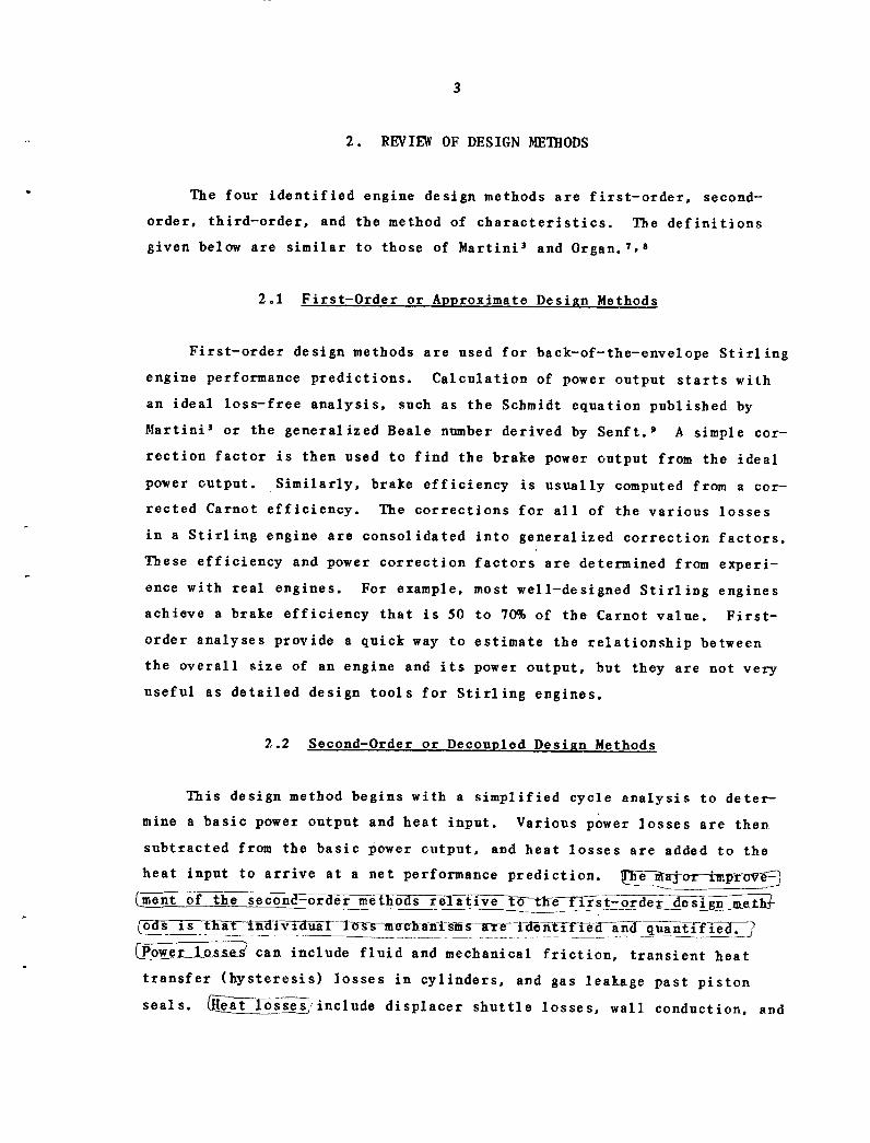
2.1 First-Order or Approximate Design Methods
First-order design methods are used for back-of-the-envelope Stirling
engine performance predictions. Calculation of power output starts with
an ideal loss-free analysis, such as the Schmidt equation published by
Martini 3 or the generalized Beale number derived by Senft. 9 A simple cor-
rection factor is then used to find the brake power output from the ideal
power output. Similarly, brake efficiency is usually computed from a cor-
rected Carnot efficiency. The corrections for all of the various losses
in a Stirling engine are consolidated into generalized correction factors.
These efficiency and power correction factors are determined from experi-
ence with real engines. For example, most well-designed Stirling engines
achieve a brake efficiency that is 50 to 70% of the Carnot value. First-
order analyses provide a quick way to estimate the relationship between
the overall size of an engine and its power output, but they are not very
useful as detailed design tools for Stirling engines.
2.2 Second-Order or Decoupled Design Methods
This design method begins with a simplified cycle analysis to deter-
mine a basic power output and heat input. Various power losses are then
subtracted from the basic power output, and heat losses are added to the
heat input to arrive at a net performance prediction. T rj-or-i.provt-
[ment of the secon -ore r methos relative ~te-fTrst-order designmejthi
(-o isth-t-in- -~d'iVij--l~-s-m e1h-an-is s-re - t-ent-i'efi-a~xd- quantifie-d
Powe rLQss-e can include fluid and mechanical friction, transient heat
transfer (hysteresis) losses in cylinders, and gas leakage past piston
seals. (e-atossesinclude displacer shuttle losses, wall conduction, and

4
imperfect heat transfer in regenerators. In all second-order design meth-
ods, it is assumed that the energy losses are not dependent on each other;
that is, they are decoupled.
Second-order design methods may be further subdivided into three
categories according to the way the variable gas volumes are handled in
the simplified cycle analysis: _sthE-iE adi, adiabat-fic, and ('f-'i=a'dTiba -t'ic .
These terms were derived according to-h't-t'ansf:errat- ee-taIs
spaces-a.d.i-enggine._cyl-inde-s.tJ If the rate is infinite, it is isothermal.
On the other hand, if the rate is zero, it is adiabatic. Semi-adiabatic
is the process somewhere in between with a limited heat transfer rate.
2.2.1 Isothermal analysis
This analysis is based on the classical Schmidt isothermal cycle,
which, by allowing for sinusoidal volume variations, is a slightly more
realistic form of the ideal Stirling cycle. All gas in the expansion
space is maintained at the heat source temperature, and all gas in the
compression space is maintained at the heat sink temperature because in-
finite heat transfer coefficients are assumed. Perfect regeneration is
also assumed (i.e., the local gas temperature is equal to the local wall
temperature in the regenerator, and there is no axial heat conduction).
All heat input to the isothermal cycle occurs in the expansion space, and
all heat output occurs in the compression space. A simple closed form
solution exists for the Schmidt cycle.
2.2.2 Adiabatic analysis
The adiabatic cycle assumes that the compression and expansion spaces
are perfectly insulated. All heat input to the cycle occurs in the heater,
and all heat output occurs in the cooler. Gases leave the heater at the
heat source temperature and are mixed perfectly as soon as they enter the
expansion space. Similarly, gases leave the cooler at the heat sink tem-
perature and are mixed perfectly as soon as they enter the compression
space. Again, perfect regeneration is assumed. The adiabatic cycle is a
more realistic simplification of a Stirling engine than the Schmidt cycle,
especially for large engines operating at high frequencies. However, an
isothermal second-order analysis can be just as accurate as an adiabatic

5
second-order analysis as long as proper adiabatic loss terms are sub-
tracted from the isothermal cycle predictions. Solution of the adiabatic
cycle requires a simple numerical integration.
2.2.3 Semi-adiabatic analysis
Semi-adiabatic cycles allow for nonzero, finite heat transfer coef-
ficients. The simplest semi-adiabatic cycle, first analyzed by Finkel-
stein,'1 accounts for heat transfer in the expansion and compression
spaces. The wall temperatures of these volumes are assumed to be constant
with respect to time and equal to the heat source and heat sink tempera-
tures, respectively. The heater, cooler, and regenerator are assumed to
behave perfectly. This semi-adiabatic cycle can actually result in effi-
ciency predictions that are lower than either the purely adiabatic cycle
or the isothermal cycle. This is caused by irreversible heat transfer
losses across the temperature difference between the gas and the cylinder
walls in the compression and expansion spaces. Solution of this semi-
adiabatic cycle requires a simple numerical integration.
2.3 Third-Order or Nodal Design Methods
Third-order design methods, also known as nodal analyses, consist of
three basic procedures: (1) divide the engine into a network of nodes or
control volumes; (2) set up the differential equations for conservation of
mass, momentum, and energy, plus equation of state for the working gas;
and (3) solve simultaneously the system of difference equations by some
adequate numerical method. There are two subclasses under this method:
one, most rigorous, and the other, less rigorous. The rigorous third-
order analyses solve all the equations except for the use of steady flow
correlations for heat transfer and friction flow because no correlations
of universal validity exist for unsteady flow in today's technology. The
less rigorous third-order models simplify the numerical computations by
omitting some of the terms from the governing differential equations. It
is assumed that certain losses can be decoupled from the main calculation
to improve the speed of computations. There are three common simplifica-
tions: (1) inertial terms are ignored in the momentum equation, but flow
6
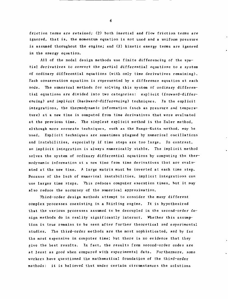
friction terms are retained; (2) both inertial and flow friction terms are
ignored, that is, the momentum equation is not used and a uniform pressure
is assumed throughout the engine; and (3) kinetic energy terms are ignored
in the energy equation.
All of the nodal design methods use finite differencing of the spa-
tial derivatives to convert the partial differential equations to a system
of ordinary differential equations (with only time derivatives remaining).
Each conservation equation is represented by a difference equation at each
node. The numerical methods for solving this system of ordinary differen-
tial equations are divided into two categories: explicit (forward-differ-
encing) and implicit (backward-differencing) techniques. In the explicit
integrations, the thermodynamic information (such as pressure and tempera-
ture) at a new time is computed from time derivatives that were evaluated
at the previous time. The simplest explicit method is the Euler method,
although more accurate techniques, such as the Runge-Kutta method, may be
used. Explicit techniques are sometimes plagued by numerical oscillations
and instabilities, especially if time steps are too large. In contrast,
an implicit integration is always numerically stable. The implicit method
solves the system of ordinary differential equations by computing the ther-
modynamic information at a new time from time derivatives that are evalu-
ated at the new time. A large matrix must be inverted at each time step.
Because of the lack of numerical instabilities, implicit integrations can
use larger time steps. This reduces computer execution times, but it may
also reduce the accuracy of the numerical approximation.
Third-order design methods attempt to consider the many different
complex processes coexisting in a Stirling engine. It is hypothesized
that the various processes assumed to be decoupled in the second-order de-
sign methods do in reality significantly interact. Whether this assump-
tion is true remains to be seen after further theoretical and experimental
studies. The third-order methods are the most sophisticated, and by far
the most expensive in computer time; but there is no evidence that they
give the best results. In fact, the results from second-order codes are
at least as good when compared with experimental data. Furthermore, some
workers have questioned the mathematical foundation of the third-order
methods: it is believed that under certain circumstances the solutions

7
may converge to values that are mathematically and computationally stable,
but do not correspond to a real physical state. In any case, more experi-
mental data are required for a fair assessment.
2.4 Method of Characteristics
The method of characteristics solves systems of nonlinear partial
differential equations of hyperbolic type by determining the character-
istic curves for the equations. The characteristic curves are used to
transform the partial differential equations into a system of ordinary
differential equations that are valid only along the characteristic curves.
This method has been used successfully in the study of compressible gas
flow and has been applied to the analysis of one-dimensional, unsteady
flow in Stirling engines.
In one-dimensional, unsteady flow, the characteristic curves are in
the position-time plane on which the partial derivatives with respect to
position and time of the fluid properties (such as density, velocity, and
temperature) are indeterminate and may, therefore, undergo arbitrary dis-
continuities. To establish the conditions for indeterminacies, the con-
servation equations (mass, momentum, energy) along with the total differ-
entials of the fluid properties are expressed in matrix notation with the
partial derivatives of the fluid properties as the dependent variables.
The characteristic curves are found by setting the determinant of the co-
efficient matrix equal to zero. For more information on the theory and
applications of the method of characteristics, readers should refer to
excellent books by Shapirol l and Leipmann and Roshko. 1 2
The method of characteristics can be applied at different levels of
complexity to Stirling engine analyses. In rigorous analyses, all three
conservation equations are solved simultaneously. In approximate analy-
ses, however, some simplifying assumptions are used to solve one of the
conservation equations independently. The two remaining conservation
equations are then solved simultaneously by the method of characteristics.

8
3. REVIEW OF MODELS
Assessments of the 19 models reviewed are presented. The reviewing
methodology consists of model description and validation. The model
descriptions present further their basic assumptions and limitations;
model validation discusses predictability and applicability. Grouping of
models fell naturally into the three major design methods: seven second-
order, ten third-order, and two methods of characteristics.
Six other Stirling engine computer models were identified, but not
reviewed. Rauch 1 3 has described a model that is based on a second-order
design method. Berggren 1 4 and Andersen T s have developed models that uti-
lize third-order design methods. Sirettl6 has developed a model that
solves the complete set of conservation equations using the method of
characteristics. Vincent et al. 1 7 of Energy Research and Generation,
Inc., give a brief description of a thermodynamic model, but insufficient
details are provided to allow a review. Models have also been developed
at Harwell,l 8 and some are thought to exist at Philips, but the authors
of this report have not acquired any documentation that describes these
models.
3.1 Second-Order Design Methods
There are seven models in this category: one isothermal, five adia-
batic, and one semi-adiabatic.
3.1.1 Model by Martini (1978) - isothermal analysis
Martinil' 3 has published detailed documentation of his second-order
model. In his analysis, Martini assumed that the time-dependent gas tem-
peratures in the expansion and compression spaces of an actual Stirling
engine can be expressed as time-averaged effective temperatures. The ef-
fective hot gas temperature will be less than the heater temperature and
the effective cold gas temperature greater than the cooler temperature.
These temperatures were derived from the computed heat transfer coeffi-
cients in both the gas heater and gas cooler as well as from the computed
heat requirement. An iterative procedure is needed as described in great
detail by Martini.

9
To validate the model, Martini 3 applied his code to two reference
engines, GPU-3 and 4L23, both of General Motors (GM). When compared with
the experimental values for the GPU-3 and the values predicted by GM for
the 4L23, Martini's calculated power and efficiency were found to be
within 20% error bands, if no correction factor for flow resistance is
used. Considerable improvement (reducing the error bands by half) can be
made if either (1) a correction factor of about 2.9 is applied to the flow
resistance coefficients, or (2) the computed heat transfer coefficients
are adjusted by a factor of 0.8.
3.1.2 Model by Qvale (1967) - adiabatic analysis
Qvale's'1 9 2 0 second-order model is based on an idealized adiabatic
cycle that has no friction or seal leakage. The pressure changes, mass
variations, piston displacements, and volume changes are all assumed to be
sinusoidal. The problem was formulated with pressure, temperature, and
mass as the independent variables. Thus, the piston displacements are com-
puted values that depend on the three independent variables. This type of
analysis is more suitable for engine synthesis than for performance pre-
dictions of a specific engine.
Ovale 19 validated his model by comparing it with the Allison PD-67A
experimental Stirling engine. His predictions for heat input, work out-
put, and indicated efficiency compare favorably with the test data over a
range of engine speed (1500 to 3000 rpm).
3.1.3 Model by Rios (1969) - adiabatic analysis
Both Rios and Qvale did their graduate work for Professor J. L. Smith
at Massachusetts Institute of Technology (MIT). Rios 2 1 expanded Qvale's
work on their adiabatic second-order model. Rios used the same basic as-
sumptions as Qvale but changed the formulation of the problem so that
nonsinusoidal piston displacements (such as those resulting from crank-
shafts with short connecting rods) could be specified.
Rios' graduate work was applied to Stirling refrigerators. However,
Martini 3 obtained the Rios computer code and modified it to suit a Stir-
ling engine application. Martini then compared the modified Rios case
with 18 data points from the GM 4L23 engine. The code overpredicted brake
power and efficiency by an average of 24 and 16%, respectively.
It"

10
3.1.4 Model by Lee et al. (1981) - adiabatic analysis
The Lee et al. 2 2 model of Foster Miller Associates is an application
of the Rios adiabatic second-order analysis. In this model, a unique
power loss mechanism was introduced. This is the cyclic heat transfer
loss (or gas spring hysteresis loss) that results from periodic heating
and cooling of the working gas near the gas-wall interfaces inside cylin-
ders, manifold spaces, connecting tubes, and reservoirs. In their appli-
cations to the Viking-1 engine, Lee et al.2 3 were able to quantify the
cyclic heat transfer loss. Among the four major power losses identified
(adiabatic, cyclic heat transfer, pressure drop, and heat exchanger AT),
it was shown that cyclic heat transfer loss was ranked second in signifi-
cance, contributing about one-third of the total power loss.
The Lee et al. 2 2 model was refined and verified by the Sunpower,
Inc., third-order analysis. For model validation, the model compared
fairly well to the GPU-3 test data. The model overpredicted the brake
power and brake efficiency by <15%, provided that a correction factor of
2.5 was applied to flow resistance.
3.1.5 Models by Shoureshi (1982) - adiabatic andisothermal analyses
With objectives in low temperature-ratio applications, Shoureshi 2 4
developed two Stirling engine mathematical models. Roth models are
second-order design methods and are called the complete model and the
simplified model.
The complete model is based on Rios' adiabatic second-order analysis.
However, updated correlations for two important losses were used: mechan-
ical friction and transient heat transfer losses. For mechanical fric-
tion, Shoureshi developed a correlation that is based on internal combus-
tion engine data. For transient heat transfer losses in the cylinders,
Shoureshi provided an alternate approach that excluded heat transfer en-
hancement factors as originally derived by Lee et al. (see Sect. 3.1.4).
To achieve an efficient optimization design method and a closed-form
solution, Shoureshi 2 5 developed a simplified model. This method involves
the Schmidt isothermal analysis plus a two-step correction for the net
power output and heat input. In the first step, an adiabatic correction
ftahl

11
(the correction from Schmidt isothermal engine analysis to adiabatic analy-
sis with perfect components) was introduced. The second step involved
deductions of all identifiable decoupled losses. These loss terms were
similar to the ones used in the adiabatic analysis of the complete model.
The procedure of the first step was to derive appropriate corrections for
the Schmidt isothermal work output with three factors: corrections for
temperature ratio, phase-angle difference between the displacer and the
piston, and dead volumes. These factors were obtained by comparing the
computed Schmidt work output with that computed from the adiabatic analy-
sis in the complete model, which was assumed to be a reference model by
Shoureshi. In addition, a correction for Carrot efficiency was determined
as a function of temperature ratio. In the process of the second step,
various losses, expressed in closed-form solutions, were further deducted
from the basic work output and added to the heat input to obtain the net
work output and heat input.
To verify the complete model, Shoureshi 24 compared his predictions
with measurements from the following high-temperature engines: Philips,
Allison, and GPU-3. It was shown that the complete model predicted engine
performance within the range of experimental uncertainty. Similar conclu-
sions were claimed for the simplified model predictions.
3.1.6 Model by Heames (1982) - adiabatic analysis
Heames et al. 26 of Argonne National Laboratory (ANL) developed a user-
oriented Stirling engine analysis code. The computer program consists of
four-modules: (1) input processor, (2) output processor, (3) standard
function module, and (4) analysis module. The input and output modules
use a flexible format that simplifies data entry and retrieval for many
different Stirling engine configurations. The two modules also provide
the capability to specify multiple computer executions for parametric stud-
ies. The output module saves the parametric results on an external file
for users with graphics capabilities. The standard function module is a
library of subprograms that provides the user with numerous correlations
and functions that are used commonly in Stirling engine analyses. In-
cluded in the function module are (1) temperature-dependent correlations

12
for the physical properties of many different fluids and metals; (2) fric-
tion factor and heat transfer correlations for many different heater,
cooler, and regenerator configurations; (3) engine heat loss correlations
such as shuttle heat transfer and cylinder wall conduction; and (4) sub-
routines to compute cylinder volume variations for different types of
crank drive mechanisms. The analysis module contains the Stirling engine
thermodynamic computations. A user will eventually be able to select from
a number of different thermodynamic algorithms. However, the only analy-
sis method in the present edition of the computer program is based on
Rios' adiabatic second-order design method. A tape copy and a user's man-
ual for ANL's Stirling engine design code will be available upon request
through the National Energy Software Center.
ANL's computer code has been validated against GPU-3 experimental
engine data. The computer predictions for indicated power output compare
favorably with the experimental data. However, the computer program ap-
pears to overestimate efficiency by as much as five percentage points,
especially at low engine speeds.
3.1.7 Model by Feurer (1973) - semi-adiabatic analysis
Philips has published very little about their Stirling engine model-
ing activities. However, a paper by Feurer 2 7 of Entwicklungsgruppe Stir-
lingmotor MAN-MWM (MAN/MWM), a Philips licensee, disclosed their semi-
adiabatic second-order analysis. This cycle is an adiabatic cycle that
allows for nonzero, finite heat transfer coefficients in the cylinders,
regenerator, and heat exchangers. The power output and efficiency are
first calculated based on this cycle, then are corrected for: (1) losses
due to nonsinusoidal crank motion, (2) residual adiabatic losses that the
simplified heat transfer coefficients do not account for, (3) flow fric-
tion losses, (4) mechanical friction losses, and (5) static conduction
losses.
In his theoretical studies, Feurer showed that all the loss mecha-
nisms are phase-angle dependent. One major conclusion is that the maximum
efficiency and the maximum power output do not occur at the same phase
angle. Model validation has not been found in the open literature because
of proprietary controls.

13
3.2 Third-Order Design Methods
There are ten models in this category: six use less rigorous meth-
ods, three use most rigorous methods, and the simplifications in the final
one (model by Zacharias, Sect. 3.2.10) were not stated clearly.
3.2.1 Model by Finkelstein (1975) - less rigorous analysis
As a pioneer in Stirling engine analysis, Finkelstein developed a
third-order method in the early 1960s. This review is based on a more
recent version published in 1975.
Finkelstein's2 8 model is a third-order design method, but less rigor-
ous than that of Urieli (see Sect. 3.2.7), which will be described later.
Finkelstein made two major assumptions in his derivation of the governing
differential equations. First, the gas kinetic energy term was ignored in
the energy equation. Second, the momentum equation was reduced to the
form of an equivalent orifice equation.
Finkelstein divided both the engine components and gas spaces into
nodal networks. The nodes were treated as regions of variable temperature
and mass. Energy and mass transfer between nodes resulted from the com-
puted temperature and pressure differences. All paths for conduction,
convection, and mass transport were included. Finkelstein used a special
technique to reduce the convergence time for finding a cyclic, steady
state, nodal temperature distribution. This was accomplished by manually
adjusting the temperatures of each metal node at the end of every piston
revolution based on net heat balances for the nodes. For example, if a
nodal heat balance across one piston cycle shows that there is a net flow
of heat into a metal node, then the temperature of the node is adjusted
upward.
Finkelstein reported that his model has been validated, but the re-
sults are not available for evaluation. However, his program is now com--
mercially available for general use on the CDC Cybernet computer system.
3.2.2 Model by Tew et ai. (1978) - common pressure analysis
The Tew et al. 2 9 '3 0 model of the National Aeronautics and Space Ad-
ministration (NASA) Lewis Research Center is a less rigorous third-order

14
design method. They used three basic equations (conservation of mass,
energy, and equation of state) to determine the thermodynamics of the gas
(temperature and mass distributions and pressure level) at each of 13
nodes. Several simplifications were used to minimize the numerical inte-
gration times: (1) the momentum equation was totally ignored and a common
pressure throughout the 13 gas nodes was assumed during each time step,
(2) kinetic energy was neglected in the energy equation, and (3) the three
processes that contribute to gas temperature changes (pressure changes,
gas mixing, and heat transfer) were treated independently. The numerical
integration required 30 to 40 piston cycles to approach cyclic steady
state distributions of gas mass and regenerator metal temperature. Pres-
sure drop, shuttle, and conduction losses were accounted for by including
these calculations only during the last cycle of the numerical integra-
tion. In the last cycle, the common pressure at each time step was as-
sumed to exist at the center of the regenerator. The compression and ex-
pansion space pressures were then calculated by estimating the pressure
drops in each control volume from steady state correlations and summing
these pressure drops. The net area enclosed by the pressure-volume curves
of the compression and expansion spaces is equal to the indicated work
output. Thus, the pressure drops are decoupled from the calculation of
mass and temperature distributions, but they do affect the work output
predictions.
Tew et al. 3 1 compared their theory with experimental data from the GM
GPU-3 Stirling engine. When the regenerator friction factor was increased
by factors of 4.0 and 2.6 for hydrogen and helium, respectively, the model
overpredicted both brake power and efficiency by 5 to 30%. Tomazic 32 also
compared the NASA-Lewis model with experimental power output data from the
USS P-40 Stirling engine. For this comparison, measured flow resistances
were used in the model rather than computed ones. The predicted brake
power values were consistently high for all engine speeds (500 to 4000
rpm) and pressures (4 to 15 MPa).
3.2.3 Model by Giansante (1980) - common pressure analysis
Giansante 3 3 of Mechanical Technology, Inc. (MTI), acquired NASA-
Lewis' code and applied it to the free-piston Stirling test engine built
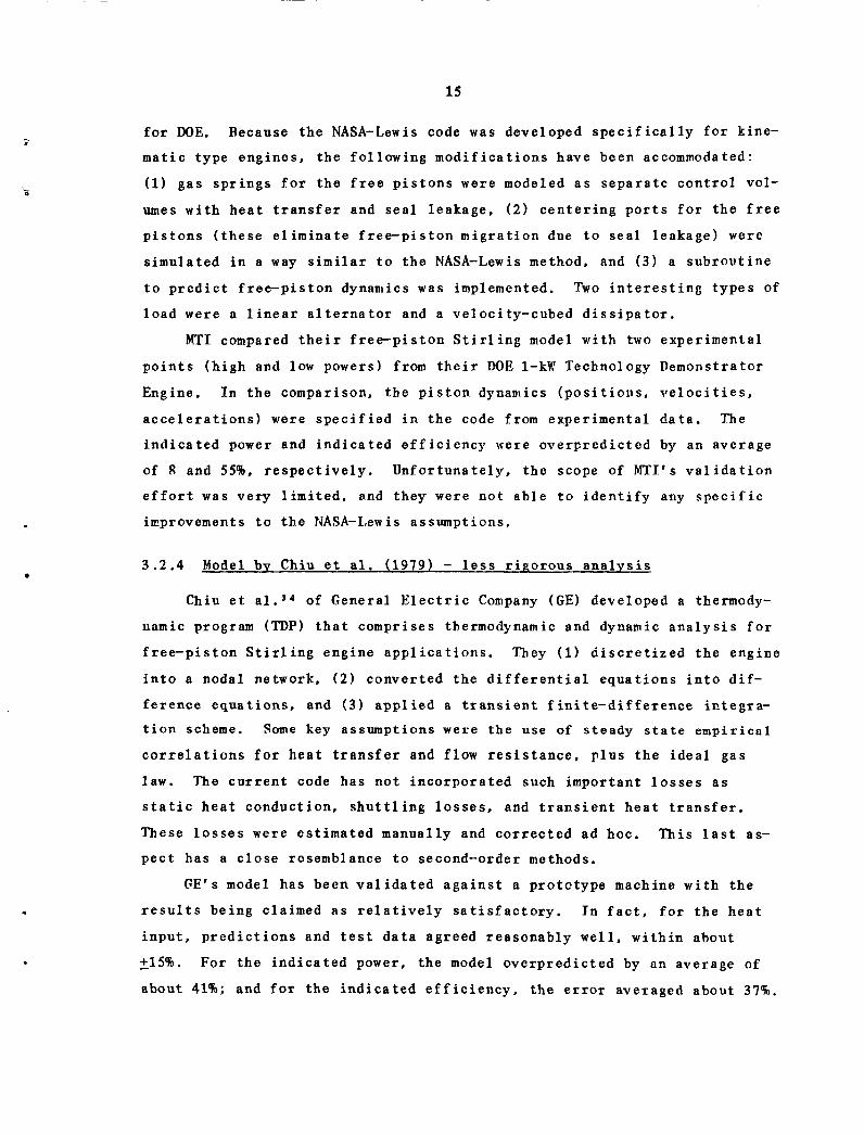
15
for DOE. Because the NASA-Lewis code was developed specifically for kine-
matic type engines, the following modifications have been accommodated:
(1) gas springs for the free pistons were modeled as separate control vol-
umes with heat transfer and seal leakage, (2) centering ports for the free
pistons (these eliminate free-piston migration due to seal leakage) were
simulated in a way similar to the NASA-Lewis method, and (3) a subroutine
to predict free-piston dynamics was implemented. Two interesting types of
load were a linear alternator and a velocity-cubed dissipator.
MTI compared their free-piston Stirling model with two experimental
points (high and low powers) from their DOE 1-kW Technology Demonstrator
Engine. In the comparison, the piston dynamics (positions, velocities,
accelerations) were specified in the code from experimental data. The
indicated power and indicated efficiency were overpredicted by an average
of g and 55%, respectively. Unfortunately, the scope of MTI's validation
effort was very limited, and they were not able to identify any specific
improvements to the NASA-Lewis assumptions.
3.2.4 Model by Chiu et al. (1979) - less rigorous analysis
Chiu et al. 34 of General Electric Company (GE) developed a thermody-
namic program (TDP) that comprises thermodynamic and dynamic analysis for
free-piston Stirling engine applications. They (1) discretized the engine
into a nodal network, (2) converted the differential equations into dif-
ference equations, and (3) applied a transient finite-difference integra-
tion scheme. Some key assumptions were the use of steady state empirical
correlations for heat transfer and flow resistance, plus the ideal gas
law. The current code has not incorporated such important losses as
static heat conduction, shuttling losses, and transient heat transfer.
These losses were estimated manually and corrected ad hoc. This last as-
pect has a close resemblance to second-order methods.
GE's model has been validated against a prototype machine with the
results being claimed as relatively satisfactory. In fact, for the heat
input, predictions and test data agreed reasonably well, within about
+15%. For the indicated power, the model overpredicted by an average of
about 41%; and for the indicated efficiency, the error averaged about 37%.

16
GE's predictions could have perhaps been made to fit the data better, but
their policy was to minimize the use of correction factors in the heat
transfer and fluid friction correlations.
3.2.5 Model by Azetsu et al. (1982) - less rigorous analysis
The Azetsu et al. 35 model, the only Japanese mathematical model pub-
lished in English, may be classified as a third-order analysis. However,
it is less rigorous than those of Urieli (Sect. 3.2.7) or Schock (Sect.
3.2.8). In many aspects, it is similar to the Tew et al. model, because
(1) a common pressure throughout all spaces was assumed, (2) gas kinetic
energy was ignored, and (3) the momentum equation was decoupled from the
other equations. A steady state momentum equation was used for pressure-
drop calculations only. Similarity also has been found in the solution
method and numerical convergence procedure. The model was designed to
adapt to various engine configurations, operating conditions, and thermal
properties.
The Azetsu et al. model was validated by a two-piston Stirling demon-
stration engine, manufactured and constructed at the University of Tokyo,
Japan. Good agreement has been obtained for P-V diagrams, cyclic tempera-
ture variation, indicated work, and thermal efficiency. They also con-
cluded that engine performance was influenced significantly by phase angle
and dead volume.
3.2.6 Model by Vanderbrug (1977) - less rigorous analysis
Vanderbrug 36 of Jet Propulsion Laboratory (JPL) presented a general
purpose program for Stirling engine analysis. The program, known as
Stirling Cycle Computer Model (SCCM), was initially designed for Stirling
engines in underwater applications. This analysis used a simplified basic
equation set in which the gas-inertial effects were ignored. Attributes
of the SCCM program include (1) thermodynamic processes for each control
volume are quasi static during a small time interval, (2) empirical or
theoretical correlations for component performance characteristics are
readily modeled by a lumped parametric (nodal) method, and (3) user-
oriented subroutines can be assembled for any particular physical systems
to be modeled.

17
Hoehn 3 7 validated Vanderbrug's model against the single JPL experi-
mental data point published so far. The net indicated power predicted by
the SCCM program was only 1% higher than the measured value, even though
the predicted magnitudes of indicated power for the individual expansion
and compression pistons were underestimated by 15 and 32%, respectively.
Hoehn also applied a Schmidt analysis to the single data point. The
Schmidt predictions were nearly as good as the SCCO model. Therefore,
many more data points are needed for a meaningful evaluation.
3.2.7 Model by Urieli (1977) - rigorous analysis
Urieli's 3 8 model is a rigorous nodal analysis. He considered the
full conservation equations by retaining the kinetic energy and the gas
inertia effects. Salient features consist of (1) piecewise approxima-
tion, that is, discretizing the engine into control volumes of various
sizes and shapes; (2) converting the partial differential equations into a
system of ordinary differential equations by transforming all differen-
tials to difference quotients except for the time variable; and (3) solv-
ing these ordinary differential equations using the fourth-order Runge-
Kutta method with a stationary initial condition. Also, the model applied
a convergence scheme that adjusts the matrix temperatures at the end of
each cycle in accordance with the net heat transferred in the control vol-
umes. Urieli stated that convergence usually occurs within ten cycles.
The program, 3 9 written in Fortran language, was fully documented. It
is efficient and very versatile. Urieli has shown that a minimal number
of cells (about 33) can be used satisfactorily to find the performance of
a particular machine, with a corresponding saving in computer time. Also,
three-dimensional plots showing the behavior of the temperature, flow, and
pressure profiles through the cycle are possible, thus helping to provide
further insight into the detailed behavior of Stirling cycle machines.
Ilrieli's model has been validated at three engine operating frequen-
cies of the University of Witwatersrand (South Africa) test engine. 4 0
When compared with the experimental data, the model underpredicted the
heat transfer rates in the heater and cooler and the power output by aver-
ages of 7, 13, and 40%, respectively. However, it is important to note

18
that these predictions are for experimental cases that produce very little
net power. Thus, errors in the net power output predictions that are
small compared with the heat input may appear rather large relative to the
small magnitude of the net power output.
3.2.8 Model by Schock (1978) - rigorous analysis
Schock of Fairchild Industries developed a Stirling Nodal Analysis
Program (SNAP), but full documentation has not been released. However, a
published paper is extensive enough for review. Schock's model 4 1 is a
rigorous third-order design method. He applied the same differential
equations as Urieli, but his method of computer modeling was different.
Schock employed a finite-difference, explicit-forward integration tech-
nique. He further developed a special scheme for enhanced mathematical
stability and for accelerated convergence to a steady state cycle. How-
ever, no details were given in the paper. Furthermore, the option of an
inertialess gas was provided for a faster but less accurate calculation.
The model has been applied to a free-piston Stirling engine built by
Sunpower, Inc., for DOF. The model predicted (1) no significant differ-
ences in cyclic pressure variation between expansion and compression
spaces; (2) nonuniform mass flow rate, which showed gas streaming out of
both ends of the regenerator at certain parts of the cycle; and (3) highly
fluctuating gas temperature profiles in each space. In addition, the
model is capable of calculating cyclic heat flow profiles, mechanical
power outputs, and energy balances in tabulated forms or three-dimensional
plots.
3.2.9 Model by Gedeon (1978) - rigorous analysis
In a highly descriptive and informative paper on the optimization of
Stirling cycle machines, Gedeon 4 2 of Sunpower, Inc., describes an optimi-
zation computer program used for the development and performance evalua-
tion of Sunpower's 1--kW engine (SPIKE). The computer program consists of
two parts: an optimization scheme and a third--order thermodynamic simula-
tion. It is the sole interest of this review to isolate and concentrate
on the thermodynamic analysis. Gedeon's third-order analysis differs from
the third-order methods used by most other investigators in two important

19
aspects. First, the working gas is divided into only six nodes: two in
the regenerator and one each in the heater, cooler, expansion space, and
compression space. The computed results changed by only a few percent
when additional control volumes were used in the analysis. Thus, it was
decided that the model with six control volumes for the working gas was
sufficiently accurate for their optimization study. In addition, a nodal
network was included to account for energy paths in the piston, displacer,
and cylinder walls. Iosses caused by shuttle heat transfer, gas spring
hysteresis, and wall conduction could all be accounted for.
The other major difference in Gedeon's thermodynamic simulation was
his integration technique. Gedeon used an implicit numerical method
to integrate the continuity, momentum, and energy equations. In implicit
integrations, the dependent nodal variables at a new time are determined
simultaneously. This requires the inversion of a large matrix at each
time step. However, long time steps can be used because implicit integra-
tion techniques are always numerically stable. Gedeon's numerical method
required about 200 time steps per piston revolution to maintain an inte-
gration accuracy of three significant figures. Losses due to gas leaks
past piston and displacer seals were properly accounted for in his mass
and energy balances. Similar to other investigators, Gedeon included a
special subroutine to accelerate the convergence of the integration toward
a cyclic steady state solution. At the end of each piston cycle, the
nodal temperatures were adjusted based on average temperatures and net
energy accumulation during the cycle. A steady solution was found in
about ten piston cycles.
Hardware development at Sunpower, Inc., has complemented and aug-
mented the development of their computer models. Gedeon claims that the
agreement between their experimental, free-piston Stirling engines and
computer predictions is within +10% for all measurable parameters. No
further details were provided by Gedeon.
3.2.10 Model by Zacharias (1977)
This review was made possible through an ORNL translation of a paper
written in German by F. Zacharias 4 3 of MAN/MWM. A full evaluation of the

20
model was not possible because few details about the model were given in
the paper. The model described by Zacharias utilizes a third-order design
method. However, it was not stated whether a complete set of conservation
equations (continuity, momentum, energy) was solved or if the gas inertia
or kinetic energy terms were neglected in the equations. Iike other third-
order models, the engine was partitioned into a network of control vol-
umes. The state of the gas in each control volume was defined by three
variables: pressure, temperature, and mass flow rate. After the conser-
vation equations were converted from differential to finite-difference
equations, they were integrated by using an explicit numerical technique.
A special algorithm was needed to accelerate the convergence of the regen-
erator nodal temperatures toward a cyclic steady state solution; but no
details were provided.
Zacharias applied the model to a four-cylinder, double-acting Stir-
ling engine. The predicted gas temperatures and pressures were presented
on three-dimensional plots as functions of position and time. A compari-
son between model predictions and experimental measurements was not in-
cluded in the paper.
3.3 Method of Characteristics
Two models were reviewed in this category. Both models are based on
some simplifying approximations that decouple one of the conservation
equations from the solution of the other two. The first model solves si-
multaneously the conservation equations of mass and momentum. The second
model is based on the simultaneous solution of the conservation equations
of mass and energy.
3.3.1 Model by OrRan (1981)
Organ 7' 8 of Cambridge University modeled an alpha-configuration
Stirling engine as a series of ducts that can branch out into parallel
paths and can have gradually changing flow areas. The gas velocity and
pressure were assumed to be functions of axial position and time. The
temperature of the gas, however, was assumed to depend only on position

21
(i.e., the gas at a particular location is isothermal). The gas tempera-
ture distribution was specified a priori and was set equal to the heater
wall temperature in the expansion cylinder and heater, the cooler wall
temperature in the compression cylinder and cooler, and a straight-line
transition from hot-end to cold-end temperature in the regenerator. For
these assumptions, the flow is defined by the conservation equations of
mass and momentum. When these equations are solved by the method of char-
acteristics, the characteristic curves are found to be the Mach lines. In
the physical plane (position-time), there are two families of Mach lines
that propagate either rightward or leftward at the local acoustic veloc-
ity relative to a moving fluid particle. The conservation equations are
integrated numerically along the Mach lines. This technique ensures that
pressure information propagates through the gas at the speed of sound.
Organ 7 applied his computer model to a Stirling machine that has
rather long heat exchangers and uses air as the working fluid. He pre-
sented a plot of the Mach line net for an instantaneous startup to 4000
rpm. Some features of the solution pertaining to the initial half revolu-
tion of crankshaft motion include: (1) a fan of rarefaction waves from
the impulsive withdrawal of the compression-space piston, (2) a triangular
dead region where the gas remains undisturbed for a finite period of time
after the instantaneous startup, and (3) a substantial change in the gra-
dient of the Macb lines across the regenerator caused by the temperature
gradient over that component. For the conditions in Organ's example, it
took about 650 of crankshaft rotation for the pressure information to
travel from one piston to the other. However, this angle would have been
considerably smaller if the heat exchangers were shorter, the engine speed
was lower, or the acoustic velocity of the working fluid was higher (using
helium or hydrogen rather than air).
Organ also presented a plot of predicted work output per cycle vs
engine speed. The net output was computed by integrating the pressures at
the surfaces of the compression and expansion pistons (after a cyclic
steady state solution was reached) with respect to the piston positions.
When Organ compared his predictions with the work output per cycle com-
puted from the ideal Schmidt analysis, it was evident that the effects of

22
fluid friction and inertia are very important, especially at high engine
speeds.
3.3.2 Model by Larson (1981)
Larson 4 4 of Cleveland State University has developed a Characteristic
Dynamic Energy Equations (CDEE) computer model based on the method of
characteristics. Larson formulated his analysis in terms of three vari-
ables: gas density, velocity, and temperature. The analysis was simpli-
fied by decoupling the momentum equation from the continuity and energy
equations and neglecting kinetic energy in the energy equation. Approxi-
mate expressions for the gas velocity and its spatial derivative were de-
rived by assuming a spatially uniform density and then correcting for the
effects of pressure drop. The approximate velocity expression enabled
Larson to (1) separate the momentum equation from the system of simulta-
neous equations and (2) compute pressure directly from the momentum equa-
tion. The continuity and energy equations along with the total differen-
tials of density and temperature form a system of hyperbolic partial dif-
ferential equations. The two characteristic curves for this system of
equations are the gas velocity and the gas velocity multiplied by the heat
capacity ratio. The characteristic directions were used to transform the
partial differential equations into a set of ordinary differential equa-
tions that are valid along the characteristic curves. These equations
were solved numerically using a fourth-fifth order Runge-Kutta integration
technique.
Iarson 4 5 applied his model to the GPU-3 configuration. Gas tempera-
tures were computer plotted as a function of position and crank angle.
Pressure-volume diagrams for the compression and expansion cylinders were
also presented for a typical set of operating conditions. When compared
with GPU-3 experimental measurements, the CDEE model overpredicted power
output by no more than 10% over the entire frequency range from 1000 to
3500 rpm. However, no details were provided about the heat transfer and
fluid friction correlations used in the model to achieve this good agree-
ment.
23
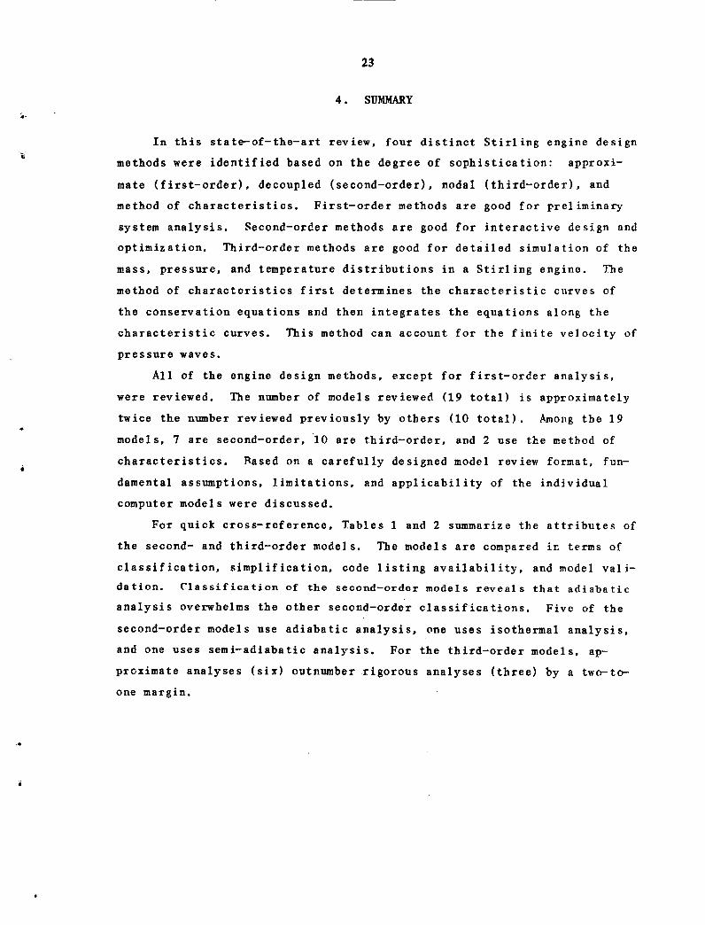
4. SUMMARY
In this state-of-the-art review, four distinct Stirling engine design
methods were identified based on the degree of sophistication: approxi-
mate (first-order), decoupled (second-order), nodal (third-order), and
method of characteristics. First-order methods are good for preliminary
system analysis. Second-order methods are good for interactive design and
optimization. Third-order methods are good for detailed simulation of the
mass, pressure, and temperature distributions in a Stirling engine. The
method of characteristics first determines the characteristic curves of
the conservation equations and then integrates the equations along the
characteristic curves. This method can account for the finite velocity of
pressure waves.
All of the engine design methods, except for first-order analysis,
were reviewed. The number of models reviewed (19 total) is approximately
twice the number reviewed previously by others (10 total). Among the 19
models, 7 are second-order, 10 are third-order, and 2 use the method of
characteristics. Based on a carefully designed model review format, fun-
damental assumptions, limitations, and applicability of the individual
computer models were discussed.
For quick cross-reference, Tables 1 and 2 summarize the attributes of
the second- and third-order models. The models are compared in terms of
classification, simplification, code listing availability, and model vali-
dation. Classification of the second-order models reveals that adiabatic
analysis overwhelms the other second-order classifications. Five of the
second-order models use adiabatic analysis, one uses isothermal analysis,
and one uses semi-adiabatic analysis. For the third-order models, ap-
proximate analyses (six) outnumber rigorous analyses (three) by a two-to-
one margin.

Table 1. Summary of Stirling engine mathematical models - second-order design methods
Principal Present Second-order Code listing Modelinvestigator affiliation classification availability validation
W. R. Martini Martini Engineering Isothermal Yesa (Ref. 3) Yes, GM GPU-3 1, 2, 3, 4and 4L23 en-gines (Ref. 3)
E. B. Qvale Laboratory for Adiabatic Not published Yes, Allison 19, 20Energetics, Denmark; PD-67A engineoriginal work done (Ref. 19)at MIT
P. A. Rios General Electric Adiabatic Yes, as modi- Yes, GM 4L23 21Company; original fied by engine, bywork done at MIT Martini Martini
(Ref. 3) (Ref. 3)
K. Lee Foster-Miller Adiabatic Not published Yes, GM GPU-3 22, 23 AAssociates engine
(Ref. 22)
R. Shoureshi Wayne State Adiabatic Yes (Ref. 24) Yes, GM GPU-3, 24, 25University Allison PD-67A,
and Philipsengines(Ref. 24)
T. J. Heames Argonne National Adiabatic Yes, from Yes, GM GPU-3 26Laboratory National engine
Energy Soft- (Ref. 26)ware Center
B. Feurer Unknown; original Semi-adiabatic Not published Not published 27work done at MAN/MWM. West Germany
Computer code (on a floppy disk) acquired by ORNL.
Computer code (on tape) acquired by ORNL.
»r r *

25
Table 2. Summary of Stirling engine mathematical models - third-order design methods
Principal Present Numerical Code listing Model
investigator affiliation simplifications availability validationferences
T. Finkelstein TCA Stirling Engine No gas inertia Available for Yes, but not 28
R&D Company or kinetic use through publishedenergy CDC Cybernet
computer
R. C. Tew NASA-Lewis Research Common pres- Yesa
(Refs. 2 Yes, GM GPU-3 29, 30, 31,Center sure, no kin- and 29) engine (Ref. 32
etic energy 31), USS P-40engine(Ref. 32)
J. E. Giansante Mechanical Tech- Common pres- Yes (Ref. 33) Limited, DOE 33nology. Inc. sure, no kin- 1-kW free-
etic energy piston engine(Ref. 33)
W. S. Chiu General Electric No gas inertia Not published Yes, GE Proto 34Company or kinetic I and 2 free-
energy piston engines(Ref. 34)
A. Azetzu University of Common pres- Not published Yes, University 35
Tokyo, Japan sure, no kin- of Tokyo testetic energy engine (Ref.
35)
T. G. Vanderbrug Unknown, original No gas inertia Yes (Ref. 36) Limited, JPL 36, 37work done at Jet Research En-
Propulsion Labora- gine (Ref.
tory 37)
I. Urieli Sunpower, Inc.; Rigorous Yes (Refs. 2 Yes, University 38, 39, 40original work done and 39) of Witwatersrand
at University of test engineWitwatersrand, (Ref. 40)
S. Africa
A. Schock Fairchild In- Rigorous Not published Yes, but not 41dustries published
D. R. Gedeon Sunpower, Inc. Rigorous Not published Yes, Sunpower 42free-pistonengines, notpublished
F. Zacharias Unknown; original Unknown Not published Not published 43work done at MAN/MWM, West Germany
A copy of early NASA-Lewis computer program acquired by ORNL.

26
5. CONCLUSIONS WITH RECOMMENDATIONS
This section provides some broad perspectives and recommendations
about analyses of Stirling engines. In the course of our study, the fol-
lowing were established: (1) a state-of-the-art review of Stirling engine
thermodynamic models, (2) an information center, and (3) a qualitative
comparison between the numerous models.
A full and complete assessment was not attempted in this report be-
cause the limited time available did not allow us to obtain all of the
documentation (especially some of the more obscure items such as theses,
reports, and lecture notes) relating to some codes. In addition, diffi-
culties were encountered with incomplete draft reports. Thus, it is rec-
ommended that comprehensive literature surveys should be continued, domes-
tically and abroad as well. For instance, on the domestic front, there
are numerous companies that are or have been outstanding in Stirling en-
gine design, application, and manufacturing; yet their documentation is
not available. Typical companies are Sunpower, Inc., and Fairchild Indus-
tries. For those companies abroad, the situation is worse. Information
from many active and leading companies in Stirling engine research and
development is scarce or not even released because of proprietary or se-
curity restrictions. Examples include Philips, Harwell, MAN/MWN, the
French, and the Japanese. Extensive communication, information exchange,
and program cooperation may improve this problem, but as long as these
organizations see a commercial or military future for Stirling machines,
some proprietary restrictions are likely to exist.
Utilization of a detailed design method does not ensure enhanced
model performance. According to our review, there is at present no evi-
dence to claim that the existing third-order and method of characteristics
analyses are superior to the second-order methods. However, it should be
pointed out that many of the models required arbitrary corrections for the
friction factor and/or heat transfer correlations to make the power output
and efficiency predictions fit the validation data better. Whether these
correction factors represent weaknesses in the models themselves or weak-
nesses in the friction and heat transfer correlations is a question that
27
must be resolved. After this question is answered, the rigorous thermo-
dynamic models will be more accurate and more generally applicable.
Contradictory opinions exist among the model developers about differ-
ences between the integration techniques used in the nodal analyses and
the method of characteristics. The point in question is the speed at
which thermodynamic information (pressure, temperature, etc.) propagates
through the engine. As discussed earlier, the nodal integrations use a
system of fixed grids and uniform time steps and can be classified into
two major categories: explicit and implicit techniques. In explicit
(forward-differencing) techniques, thermodynamic information propagates
only from one node to an adjacent node during each time step. The node
spacing and time step, therefore, determine the speed at which information
propagates through the grid system. The explicit techniques are sometimes
plagued by numerical instabilities, if the time steps are improperly
chosen. In contrast, the implicit (backward-differencing) technique is
always numerically stable, regardless of grid spacings and time steps.
The implicit technique solves the finite difference equations describing
*r ~ the state of the working fluid by calculating the condition of the gas in
each cell at a particular time from the condition of the gas in all other
cells at that time. Consequently, thermodynamic information can propagate
from one end of the engine to the other during one time step.
Numerical integrations using the method of characteristics are nor-
mally based on fixed time steps and floating grids. The choice of grid
spacing depends on the characteristic curves of the governing equations.
In Organ's model, in which the method of characteristics was applied to
the conservation equations of mass and momentum, the nodes are spaced so
that the pressure information propagates at the local acoustic velocity
relative to the local gas velocity.
It may be very important to account for the fact that pressure waves
propagate at the speed of sound when predicting the performance of certain
engines, especially ones that have long heat exchangers and operate at
high frequencies. However, this effect may not be very important in other
~* ~ engines, and the nodal integration techniques may provide sufficient ac-
curacy. This is a dilemma that will only be resolved by further investi-
gation.

28
We are not in a position now to rank with confidence the models re-
viewed. The only fair way to compare the models would be to run all of
the codes on the same computer and compare their predictions with data
from well-defined experimental Stirling engines. Some work along these
lines was begun by ANL. 4 6 However, this is a difficult task for three
apparent reasons. First, every model has its unique attributes and may
also be applicable only to a limited number of engine configurations.
Second, acquisition of codes would have to be limited to nonproprietary
codes. Finally, a lack of well-defined experimental data is a hindrance.
Numerous investigators have published experimental data, but many of them
have not provided enough information about engine dimensions, parameter
definitions, and even the operating conditions to allow a meaningful com-
parison between simulation and experiment.
It is obvious that a large variety of thermodynamic models for Stir-
ling engine analysis has been developed. They range in complexity from
the simple first-order models up through the rigorous third-order and
method of characteristics models. It does not seem necessary to develop
any new thermodynamic models. Time and effort would be better spent by
increasing our understanding of the existing models. One final observa-
tion is that validation of the thermodynamic models has been limited
mainly to kinematic engines. When experimental data from free-piston
Stirling engines have been used to validate the models, the experimentally
determined dynamic parameters (such as frequency, phase angle, and piston
amplitudes), rather than predicted values from a separate free-piston
dynamics model, have usually been used as inputs to the thermodynamic
models. Analyses of free-piston dynamics have been explored to a much
lesser extent than those of Stirling engine thermodynamics, but it is an
area that is important and needs additional studies.

29
ACKNOWLEDGMENTS
The preparation of this report was supported by the Department of
Energy as part of the Stirling Cycle Heat Engine Technology Program, man-
aged by P. D. Fairchild of ORNL Energy Division.
The authors are indebted to C. D. West and J. I,. Crowley of ORNL En-
gineering Technology Division for reviewing the manuscript and offering
useful comments. In addition, the authors of the models reviewed in this
report were solicited for comments. (Note: Sect. 3.2.10 was added to
this report too late to provide F. Zacharias this opportunity.) The con-
structive responses received from the ten model developers listed below
were greatly appreciated.
W. S. Chiu - General Electric Company
D. R. Gedeon - Sunpower, Inc.
F. W. Hoehn - Rockwell International (former colleague ofT. G. Vanderbrug)
V. H. Larson - Cleveland State University
W. R. Martini - Martini Engineering
A. J. Organ - Cambridge University
E. B. O.vale - The Technical University of Denmark
P. A. Rios - General Electric Company
R. Shoureshi - Wayne State University
R. C. Tew - NASA-Lewis Research Center
a

30
REFERENCES
1. W. R. Martini, Stirling Engine Design ManuaZ, NASA-CR-1353 82, Natl.Aeronautics and Space Administration, April 1978.
2. W. R. Martini, Thermodynamic Design of Stirling Engines by Computer,Martini Engineering, Richland, Washington, 1980.
3. W. R. Martini, Stirling Engine Design Manual - Second Edition, to bepublished by NASA-Lewis.
4. W. R. Martini, "Validation of Published Stirling Engine Design Meth-ods Using Engine Characteristics from the Literature," pp. 2245-50 inProceedings of the 15th IECEC, Paper No. 809449, 1980.
5. 1. Urieli, "A Review of Stirling Cycle Machine Analysis," pp. 1086-90in Proceedings of the 14th IECEC, Paper No. 799236, 1979.
6. G. Walker, Stirling Engines, Clarendon Press, Oxford, 1980.
7. A. J. Organ, "Gas Dynamics in the Temperature-Determined StirlingCycle," J. Mech. Eng. Sci. 23(4), 207-16 (August 1981).
8. A. J. Organ, "Gas Dynamics of Stirling Cycle Machines, Stirling Fn-gines - Progress Toward Reality," pp. 131-40 in Mechanical Engineer-ing Publications Limited, London (March 1982).
9. J. R. Senft, "A Simple Derivation of the Generalized Reale Number,"pp. 1652-55 in Proceedings of the 17th IECEC, Paper No. 829273,1982.
10. T. Finkelstein, Generalized Thermodynamic Analysis of Stirling En-gines, SAE Paper No. 118B, Society of Automotive Engineers, January1960.
11. A. P. Shapiro, The Dynamics and Thermodynamics of Compressible FluidFlow - Vols. I and II, Ronald Press, New York, 1953.
12. H. W. I,iepmann and A. Roshko, Elements of Gasdynamics, John Wiley andSons, New York, 1957.
13. J. S. Rauch, "Harmonic Analysis of Stirling Engine Thermodynamics,"pp. 1696-1700 in Proceedings of the 15th IECEC, Paper No. 809335,1980.
14. R. Berggren, Analysis Documentation - STENSY, Interim No. 1, MTI Re-port No. 82 ASE286ER46, Mechanical Technology, Inc. (March 1983).
15. N. E. Andersen, Stirling Engine Modular Analysis Program (SEMAP),Laboratory for Energetics, Technical University of Denmark, RE 79-9,1979.

31
16. E. J. Sirett, "The Gas Dynamics of the Stirling Machine," first yearreport on postgraduate work, Cambridge University Engineering Dept.,1981.
17. R. Vincent, W. Rifkin, and G. Benson, "Analysis and Design of Free-Piston Stirling Engines - Thermodynamics and Dynamics," pp. 3686-95in Proceedings of the 15th IECEC, Paper No. 809334, 1980.
18. R. Howlett, A Digital Computer Simulation of the ThermomechanicalGenerators, AERE-M2294, Atomic Energy Research Establishment, UnitedKingdom, 1970.
19. E. B. Ovale and J. I. Smith, Jr., "A Mathematical Model for SteadyOperation of Stirling-Type Engines," J. Eng. Power, 45-50 (January1968).
20. E. B. Ovale, An Analytical Model of Stirling-Type Engines, Ph.D.Thesis, Massachusetts Institute of Technology, 1967.
21. P. A. Rios, An Analytical and Experimental Investigation of theStirling Cycle, Ph.D. Thesis, Massachusetts Institute of Technology,1969.
22. K. Iee, I. P. Krepchin, and W. M. Toscano, "Thermodynamic Descriptionof an Adiabatic Second Order Analysis for Stirling Engines," pp.1919-24 in Proceedings of the 16th IECEC, Paper No. 819794, 1981.
23. K. Iee et al., "Performance Loss Due to Transient Heat Transfer inthe Cylinders of Stirling Engines," pp. 1706-1909 in Proceedings ofthe 15th IECEC, Paper No. 809338, 1980.
24. R. Shoureshi, Analysis and Design of Stirling Engines for Waste-HeatRecovery, Ph.D. Thesis, Massachusetts Institute of Technology, 1981.
25. R. Shoureshi, "Simple Models for Analysis and Design of PracticalStirling Engines," pp. 1647-51 in Proceedings of the 17th IECEC,Paper No. 829272, 1982.
26. T. J. Heames et al., "A User Oriented Design System for StirlingCycle Codes," pp. 1681-87 in Proceedings of the 17th IECEC, PaperNo. 829278, 1982.
27. B. Feurer, "Degrees of Freedom in the Layout of Stirling Engines,"presented at Von Kaman Institute for Fluid Dynamics - Lecture Series53, Feb. 12-16, 1973.
28. T. Finkelstein, "Computer Analysis of Stirling Engines," pp. 933-41in Proceedings of the 10th IECEC, Paper No. 759140, 1975.
a

32
29. R. Tew, K. Jefferies, and D. Miao, A Stirling Engine Computer ModelFor Performance Calculations, NASA TM-78884, Natl. Aeronautics andSpace Administration, July 1978.
30. R. C. Tew, Computer Program for Stirling Engine Performance Calcula-tions, NASA/TM-82960, Natl. Aeronautics and Space Administration,January 1983.
31. R. C. Tew, I,. G. Thieme, and D. Miao, Initial Comparison of SingleCylinder Stirling Engine Computer Model Predictions with Test Re-sults, NASA 1M-79044, Natl. Aeronautics and Space Administration,March 1979.
32. W. A. Tomazic, Supporting Research and Technology of AutomotiveStirling Engine Development, NASA TM-81495, Natl. Aeronautics andSpace Administration, April 1980.
33. J. E. Giansante, A Free Piston Stirling Engine Performance Code81TR17, prepared for NASA-Lewis by Mechanical Technology, Inc.,November 1980.
34. General Electric, The Thermodynamic Program (TDP) for Free-PistonStirling Engine/Linear Compressor Simulation, GE No. GFHP-82-048,1982.
35. A. Azetsu, N. Nakajima, and M. Iirata, "Computer Simulation Model forStirling Engine," pp. 57-63 in Stirling Engines -Progress TowardsReality, Mechanical Engineering Publications Limited, London, March1982.
36. J. G. Finegold and T. G. Vanderbrug, Stirling Engines for UnderseaVehicles - Final Report, JPL No. 5030-63, Jet Propulsion Laboratory,March 1977.
37. F. W. Hoehn, B. D. Nguyen, and D. D. Schmit, "Preliminary Test Re-sults with a Stirling Laboratory Research Engine," pp. 1075-81 inProceedings of the 14th IECEC, Paper No. 799233, 1979.
38. I. Urieli, C. J. Rallis, and D. M. Berchowitz, "Computer Simulationof Stirling Cycle Machines," pp. 1512-21 in Proceedings of the 12thIECEC, Paper No. 779252, 1977.
39. 1. Urieli, A Computer Simulation of Stirling Cycle Machines, Ph.D.Thesis, University of Witwatersrand, South Africa, 1977.
40. D. M. Rerchowitz and C. J. Rallis, "A Computer and Experimental Simu-lation of Stirling Cycle Machines," pp. 1730-38 in Proceedings of the13th IECEC, Paper No. 789111, 1978.
41. A. Schock, "Nodal Analysis of Stirling Cycle Devices," pp. 1771-79in Proceedings of the 13th IECEC, Paper No. 789191, 1978.
33
42. D. R. Gedeon, "The Optimization of Stirling Cycle Machines," pp.1784-90 in Proceedings of the 13th IECEC, Paper No. 789193, 1978.
43. F. Zacharias, "Further Stirling Engine Development Work - Part 1,"Motortech. Z. 38(9), 371-77 (1977).
44. V. H. Larson, "Characteristic Dynamic Energy Equations for StirlingCycle Analysis," pp. 1942-47 in Proceedings of the 16th IECEC, PaperNo. 819798, 1981.
45. V. H. Iarson, "Computation Techniques and Computer Programs to An-alyze Stirling Engines Using Characteristic Dynamic Energy Equa-tions," pp. 1710-15 in Proceedings of the 17th IECEC, Paper No.829283, 1982.
46. J. E. Ash and T. J. Reames, "Comparative Analysis of Computer Codesfor Stirling Engine Cycles," pp. 1936-41 in Proceedings of the 16thIECEC, Paper No. 819797, 1981.

35
ORNL/CON-135
Internal Distribution
1. F. Chen 26. J. E. Jones2-6. N. C. J. Chen 27. R. E. MacPherson
7. J. T. Cockburn (Consultant) 28. S. S. Mason (Consultant)8. J. C. Conklin 29. J. W. Michel9. F. A. Creswick 30. R. E. Minturn
10. J. L. Crowley 31. J. Petrykowski11. N. Domingo 32. G. T. Privon12. R. D. Ellison 33. S. D. Rose13. P. D. Fairchild 34. R. L. Rudman (Consultant)14. E. C. Fox 35. J. P. Sanders15. R. L. Graves 36. H. E. Trammell
16-20. F. P. Griffin 37. C. D. West21. D. S. Griffith 38. ORNL Patent Office22. T. J. Hanratty (Consultant) 39. Central Research Library23. V. O. Haynes 40. Document Reference Section24. H. W. Hoffman 41-42. Laboratory Records Department25. W. L. Jackson 43. Laboratory Records (RC)
External Distribution
44. Thierry Alleau, Commissariat a l'Engergie Atomique, Centred'Etudes Nuclearies de Grenoble, Service des Transferts Termiques,85X, 38041 GRENOBLE CEDEX, France
45. A. Azetsu, Department of Mechanical Engineering, University ofTokyo, Japan
46. W. T. Beale, Sunpower, Inc., 6 Byard St., Athens, OH 4570147. Donald G. Beremand, Stirling Engine Project Office, National
Aeronautics and Space Administration, Lewis Research Center,Cleveland, OH 44135
48. Stig G. Carlqvist, Societe ECA, 17, avenue du Chateau, 92190Meudon-Bellevue, France
49. W. S. Chiu, Systems Engineering, General Electric Company, P.O.Box 527, King of Prussia, PA 19406
50. J. G. Daley, Argonne National Laboratory, 9700 South Cass Avenue,Argonne, IL 60439
51. B. Feurer, MAN-AG, Maschinenfabrik Augsburg-Nurnberg AG, Postfach10 00 80, D-8900 Augsburg 1, West Germany
52. T. Finkelstein, TCA, P.O. Box 643, Beverly Hills, CA 9021353. D. R. Gedeon, Sunpower, Inc., 6 Byard St., Athens, OH 4570154. J. E. Giansante, Mechanical Technology Inc., Stirling Engine Sys-
tems Division, 968 Albany-Shaker Road, Latham, NY 1211055. L. Goldberg, University of Minnesota, The Underground Space Cen-
ter, 11 Mines and Metallurgy, 221 Church Street, SE, Minneapolis,MN 55455

36
56. T. J. Heames, Argonne National Laboratory, 9700 South Cass Avenue,Argonne, IL 60439
57. F. W. Hoehn, Rockwell International Corp., 6633 Canoga Avenue,Canoga Park, CA 91304
58. R. E. Holtz, Argonne National Laboratory, 9700 South Cass Avenue,Argonne, IL 60439
59. Y. Ishizaki, Cryogenic Systems, 253-5 Yamanouchi, Kamakura 247,Japan
60. Naotsugu Isshiki, 2-29-6 Kyodo Setagayaku, Tokyo 156, Japan61. Prof. Nobuhide Kasagi, University of Tokyo, Dept. of Mechanical
Engineering, Bunkyo-Ku, Tokyo 113, Japan62. V. H. Larson, Cleveland State University, 1983 East 24th St.,
Cleveland, OH 4411563. K. P. Lee, Manager, Facility and Manufacturing Automation, P.O.
Box 809, Sudbery, MA 0177664. W. Martini, Martini Engineering, 2303 Harris, Richland, WA 9935265. G. McLennan, Argonne National Laboratory, 9700 South Cass Avenue,
Argonne, IL 6043966. Vincenzo Naso, Prof. Ing., Universita Degli Studi Di Roma, Insti-
tuto Di Macchine E Tecnologie Meccaniche, Rome, Italy67. A. J. Organ, University Engineering Department, Trumpington St.,
Cambridge, CB2 1PZ, England68. E. B. Qvale, Laboratory for Energetics, Technical University of
Denmark, Bldg. 403 DK-2800, Lyngby, Denmark69. C. J. Rallis, School of Mechanical Engineering, University of the
Witwatersrand, 1, Jan Smuts Avenue, Johannesburg, South Africa70. Lt. Cdr. G. T. Reader, Royal Naval Engineering College, Manadon
Plymouth, Devon PL5 3AQ, England71. G. Rice, Department of Engineering, The University of Peading,
Reading, Berkshire, England72. P. A. Rios, Electromechanics Branch, Electrical Systems and Tech-
nology Laboratory, General Electric R and D Center, P.O. Box 43,Schenectady, NY 12301
73. J. R. Senft, Dept. of Mathematics/Computer Systems, University ofWisconsin-River Falls, River Falls, WI 54022
74. B. Shaddis, Mueller Associates, 1401 South Edgewood St., Balti-more, MD 21227
75. A. Schock, Fairchild Industries, Germantown, MD 2087476. R. Shoureshi, Wayne State University, Detroit , MI 4820277. R. C. Tew, NASA-Lewis Research Center, 21000 Brockpark Rd.,
Cleveland, OH 4413578. I. Urieli, Sunpower, Tnc., 6 Byard St., Athens, OH 4570179. Valerie J. Van Griethuysen, Energy Conversion Branch, Aerospace
Power Division - Aero Propulsion Laboratory, Dept. of the AirForce, Wright-Patterson AFB, OI1 45433
80. G. Walker, University of Calgary, Dept. of Mechanical Engineering,2920 24th Ave., NW, Calgary, Canada TZN 1N4
81. M. A. White, University of Washington, Joint Center for GraduateStudy, 100 Sprout Road, Richland, WA 99352

37
82. Office of Assistant Manager for Energy Research and Development,Department of Energy, ORO, Oak Ridge, TN 37830
83-109. Technical Information Center, Department of Energy, Oak Ridge, TN37830

I�z
4


![Making Stirling Engines[1]](https://static.fdocuments.us/doc/165x107/545fddcdb1af9f1d618b4690/making-stirling-engines1.jpg)

![Making Stirling Engines[1].pdf](https://static.fdocuments.us/doc/165x107/54961e7dac7959f66f8b4588/making-stirling-engines1pdf-55846653e03f2.jpg)