
Stinger Reference Guide - ip-sa · commands, and details the ... Stinger Reference Guide 1-3...
330
Stinger Reference Guide Part Number: 7820-0713-001 For software version 7.11 August 1999
Transcript of Stinger Reference Guide - ip-sa · commands, and details the ... Stinger Reference Guide 1-3...

Stinger Reference Guide
Part Number: 7820-0713-001For software version 7.11
August 1999

Copyright© 1999 Lucent Tec hnologies. All Rights Reserved.
This material is protected by the copyright laws of the United States and other countries. It may not be reproduced, distributed, or altered in any fashion by anyentity (either internal or external to Lucent Technologies), except in accordance with applicable agreements, contracts, or licensing, without the expresswritten consent of Lucent Technologies.
Notice
Every effort was made to ensure that the information in this document was complete and accurate at the time of printing. However, information is subject tochange.
Security Statement
In rare instances, unauthorized individuals make connections to the telecommunications network through the use of access features.
Trademarks
Ascend Access Control, Dynamic Bandwidth Allocation, FrameLine, Hybrid Access, MAX, MAX TNT, Multilink Protocol Plus, Pipeline, Secure Access,and Series56 are trademarks of Lucent Technologies. Other trademarks and trade names mentioned in this publication belong to th eir respective owners.
Ordering Information
To order copies of this document, contact your Lucent Technologies representative or reseller.
Support Telephone Numbers
For a menu of support and other services, call (800) 272-3634. Or call (510) 769-6001 for an operator.
Lucent Technologies

e.
S
e
tor.
Customer ServiceCustomer Service provides a variety of options for obtaining information about Lucent products and services, software upgrades, and technical assistance.
Finding information and software on the Internet
Visit the Web site at http://www.ascend.com for technical information, product information, and descriptions of available services.
Visit the FTP site at ftp.ascend.com for software upgrades, release notes, and addenda to this manual.
Obtaining technical assistance
You can obtain technical assistance by telephone, email, fax, modem, or regular mail, as well as over the Internet.
Enabling Lucent to assist you
If you need to contact Lucent for help with a problem, make sure that you have the following information when you call or that you include it in your correspondence:
• Product name and model.
• Software and hardware options.
• Software version.
• If supplied by your carrier, Service Profile Identifiers (SPIDs) associated with your lin
• Your local telephone company’s switch type and operating mode, such as AT&T 5ESCustom or Northern Telecom National ISDN-1.
• Whether you are routing or bridging with your Lucent product.
• Type of computer you are using.
• Description of the problem.
Calling Lucent from within the United States
In the U.S., if you need to talk to an engineer right away, call (900) 555-2763 to reach thePriority Call queue. The charge of $2.95 per minute does not begin to accrue until you arconnected to an engineer. Average wait times are less than three minutes.
For a menu of Lucent’s services, call (800) 272-363). Or call (510) 769-6001 for an opera
Stinger Reference Guide iii
.S.
Calling Lucent from outside the United States
You can contact Lucent by telephone from outside the United States at one of the following numbers:
Obtaining assistance through correspondence
Lucent maintains two email addresses for technical support questions. One is for customers in the United States, and the other is for customers in Europe, the Middle East, and Asia. If you prefer to correspond by fax, BBS, or regular mail, please direct your inquiry to Lucent’s Uoffices. Following are the ways in which you can reach Customer Service:
• Email from within the U.S.—[email protected]
• Email from Europe, the Middle East, or Asia—[email protected]
• Fax—(510) 814-2312
• Customer Support BBS (by modem)—(510) 814-2302
Write to Lucent at the following address:
Attn: Customer ServiceLucent Technologies Inc.1701 Harbor Bay ParkwayAlameda, CA 94502-3002
Telephone outside the United States (510) 769-8027
Austria/Germany/Switzerland (+33) 492 96 5672
Benelux (+33) 492 96 5674
France (+33) 492 96 5673
Italy (+33) 492 96 5676
Japan (+81) 3 5325 7397
Middle East/Africa (+33) 492 96 5679
Scandinavia (+33) 492 96 5677
Spain/Portugal (+33) 492 96 5675
UK (+33) 492 96 5671
For the Asia Pacific Region, you can find additional support resources at http://apac.ascend.com
iv Stinger Reference Guide

Contents
About This Guide ............................................................................. vii
What is in this guide................................................................................................................ viiWhat you should know ........................................................................................................... viiDocumentation conventions.................................................................................................... viiDocumentation set.................................................................................................................. viiiRelated publications............................................................................................................... viii
Chapter 1 Stinger Command Reference......................................................... 1-1
Chapter 2 Stinger Profile and Parameter Reference..................................... 2-1
A............................................................................................................................................. 2-2B ........................................................................................................................................... 2-36C ........................................................................................................................................... 2-44D........................................................................................................................................... 2-59E ........................................................................................................................................... 2-71F ........................................................................................................................................... 2-79G........................................................................................................................................... 2-84H........................................................................................................................................... 2-85I ............................................................................................................................................ 2-88L ......................................................................................................................................... 2-101M ........................................................................................................................................ 2-114N......................................................................................................................................... 2-125O......................................................................................................................................... 2-129P ......................................................................................................................................... 2-132Q......................................................................................................................................... 2-145R ......................................................................................................................................... 2-147S ......................................................................................................................................... 2-165T ......................................................................................................................................... 2-205U......................................................................................................................................... 2-220V......................................................................................................................................... 2-228W........................................................................................................................................ 2-234Y......................................................................................................................................... 2-236
Chapter 3 Progress and Disconnect Codes................................................... 3-1
Progress codes........................................................................................................................ 3-1Disconnect-cause codes ......................................................................................................... 3-3
Index.......................................................................................... Index-1
Stinger Reference Guide v


Stinger Reference Guide
About This Guide
uld
char-
ear
in t,
bold
What is in this guideThis guide provides an alphabetical reference to all the Stinger profiles, parameters, and commands, and details the settings and options you can specify.
Note: This manual describes the full set of features for Stinger units running software version 7.11. Some features might not be available with earlier versions or specialty loads of the software.
! Warning: Read the safety instructions in the hardware installation guide before installing the product.
What you should knowThis guide is intended for the person who will configure and maintain the Stinger. To use it effectively, you must have a basic understanding of Stinger security and configuration, and be familiar with authentication servers and networking concepts.
Documentation conventionsFollowing are all the special characters and typographical conventions used in this manual:
Convention Meaning
Monospace text Represents text that appears on your computer’s screen, or that coappear on your computer’s screen.
Boldface mono-space text
Represents characters that you enter exactly as shown (unless theacters are also in italics—see Italics, below). If you could enter the characters but are not specifically instructed to, they do not appin boldface.
Italics Represent variable information. Do not enter the words themselvesthe command. Enter the information they represent. In ordinary texitalics are used for titles of publications, for some terms that would otherwise be in quotation marks, and to show emphasis.
[ ] Square brackets indicate an optional argument you might add to a command. To include such an argument, type only the information inside the brackets. Do not type the brackets unless they appear in type.
| Separates command choices that are mutually exclusive.
vii

About This GuideDocumentation set
g
at
e rs
ple,
m-
ult
sult
Documentation setThe Stinger documentation set consists of the following manuals:
• Stinger Hardware Installation Guide. Describes how to install the Stinger hardware. Includes technical specifications and architectural overview.
• Stinger Configuration Guide. Describes how to configure VPI/VCI pairs, Connection
profiles, management interfaces, and QoS.
• Stinger Reference Guide (this manual). An alphabetic reference to all Stinger profiles, parameters, and commands.
• Stinger Administration Guide. Contains operation and maintenance information.
• TAOS Command Line Interface Guide. Shows you how to use the Stinger command-line
interface effectively.
Related publicationsThis guide and documentation set do not provide a detailed explanation of products,
architectures, or standards developed by other companies or organizations. The followin
sections list some publications that you might find useful.
ITU-T recommendations
ITU-T recommendations (formerly CCITT) are available commercially. You can order them
http://www.itu.ch/publications/.
> Points to the next level in the path to a parameter or menu item. Thitem that follows the angle bracket is one of the options that appeawhen you select the item that precedes the angle bracket.
Key1-Key2 Represents a combination keystroke. To enter a combination key-stroke, press the first key and hold it down while you press one or more other keys. Release all the keys at the same time. (For examCtrl-H means hold down the Control key and press the H key.)
Press Enter Means press the Enter, or Return, key or its equivalent on your coputer.
Note: Introduces important additional information.
!Warning:
Warns that a failure to follow the recommended procedure could resin loss of data or damage to equipment, or physical injury.
Warning:
Warns that a failure to take appropriate safety precautions could rein electrical shock.
Convention Meaning
viii Stinger Reference Guide
About This GuideRelated publications
Related books
The following books are available in technical bookstores.
• Routing in the Internet, by Christian Huitema. Prentice Hall PTR, 1995. Recommendedfor information about IP, CIDR, IP multicast, and mobile IP.
• SNMP, SNMPV2 and RMON: Practical Network Management, by William Stallings. Addison-Wesley, 1996. Recommended for network management information.
• TCP/IP Illustrated, volumes 1&2, by W. Richard Stevens. Addison-Wesley, 1994.
Stinger Reference Guide ix


Stinger Reference Guide
1
Stinger Command Referencethe
The information contained here is designed for quick reference, and does not include tutorials. All commands are listed alphabetically. For an overall alphabetic listing, see the general table of contents.
You can display a usage summary for any command by entering a question mark and the name of the command:
admin> ? command-name
For an alphabetic list of commands, just enter a question mark:
admin> ?
The command line accepts a maximum of 80 characters, including the prompt.
Note: If the list of commands displayed as output does not include all of the commands described in this chapter, you might need to authenticate a User profile that has more extensive permissions. For details, see “Auth” on page 1-6.
?
Description: Displays a list of all available commands, or help text about a specific command. A list of all available commands also shows the permission level required for use of each command.
Permission level: User
Usage: ? [-a]|[command-name]
Option Description
–a List all commands. (Without this option, the list includes only commands authorized by the current User profile.)
command-name Display information about the specified command.
1-1

Stinger Command Reference?
Example: To display a list of commands authorized for your current login:
admin> ?? ( user )atmtrunkreset ( diagnostic )atmtrunks ( system )auth ( user )clear ( user )clock-source ( diagnostic )clr-history ( system )connection ( system )date ( update )debug ( diagnostic )delete ( update )device ( diagnostic )dir ( system )dircode ( system )ether-display ( diagnostic )fatal-history ( system )format ( code )fsck ( code )get ( system )help ( user )if-admin ( diagnostic )[More? <ret>=next entry, <sp>=next page, <^C>=abort]
To display help text about a command:
admin> ? dirdir list all profile typesdir profile-type list all profiles of the specified typedir profile-type profile-index list the specified profile instance
Dependencies: The current security level is set by the current User profile and determines which commands are displayed in response to the ? command. If the current User profile does not have sufficient privileges to execute a command, that command is not displayed unless you include the -a option. By default, commands with the User security level are always displayed. For details, see “Auth” on page 1-6.
See Also: Help, Auth
1-2 Stinger Reference Guide
Stinger Command ReferenceARPtable
ARPtable
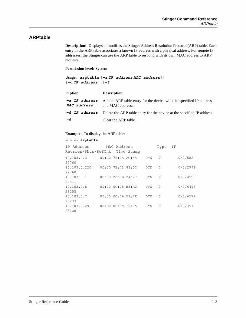
Description: Displays or modifies the Stinger Address Resolution Protocol (ARP) table. Each entry in the ARP table associates a known IP address with a physical address. For remote IP addresses, the Stinger can use the ARP table to respond with its own MAC address to ARP requests.
Permission level: System
Usage: arptable [-a IP_address MAC_address]|[-d IP_address]|[-f]
Example: To display the ARP table:
admin> arptable
IP Address MAC Address Type IF Retries/Pkts/RefCnt Time Stamp
10.103.0.2 00:C0:7B:7A:AC:54 DYN 0 0/0/552
22760
10.103.0.220 00:C0:7B:71:83:02 DYN 0 0/0/2791
22760
10.103.0.1 08:00:20:7B:24:27 DYN 0 0/0/4296
22811
10.103.0.8 00:00:0C:05:B3:A2 DYN 0 0/0/6493
23058
10.103.0.7 00:00:0C:76:58:4E DYN 0 0/0/6572
23233
10.103.0.49 00:C0:80:89:19:95 DYN 0 0/0/397
23208
Option Description
–a IP_address MAC_address
Add an ARP table entry for the device with the specified IP address and MAC address.
-d IP_address Delete the ARP table entry for the device at the specified IP address.
-f Clear the ARP table.
Stinger Reference Guide 1-3

Stinger Command ReferenceATMTrunkReset
ci-
t.
r
The ARP table displays the following information:
To add an ARP table entry for a device with the physical address 00A024A61535 at IP address 10.9.8.20:
admin> arptable -a 10.9.8.20 00A024A61535
See Also: NSlookup
ATMTrunkReset
Description: Resets the unit’s Trunk Modules (TMs)
Permission level: Diagnostic
Usage: atmtrunkreset [-17|-18]
See Also: ATMtrunks
Column Description
IP Address The address contained in ARP requests.
MAC Address The MAC address of the host.
Type How the address was learned, that is, dynamically (DYN) or by spefication of a static route (STAT).
IF The interface on which the Stinger received the ARP request.
Retries The number of retries needed to refresh the entry after it timed out.
Pkts The number of packets sent out to refresh the entry after it timed ou
RefCnt The number of times the Stinger consulted the entry.
Time Stamp The number of seconds since the system has come up. The Stingeupdates this column every time an ARP entry is refreshed.
Option Description
no argument Display options.
-17 Reset TM 1.
-18 Reset TM 2.
1-4 Stinger Reference Guide

Stinger Command ReferenceATMtrunks
he
ce is the nger
ATMtrunks
Description: Displays Asynchronous Transfer Mode (ATM) trunk use.
Permission level: System
Usage: atmtrunks [-a|-d|-f|-u]
Example: To display all ATM trunks:
All OC3 ATM trunks:
OC3 Lines (dvOp dvUpSt dvRq sAdm nailg)
Line { 1 17 1 } (Up Idle UP UP 00801)
Line { 1 17 2 } (Up Idle UP UP 00802)
The data displayed includes the physical address of each line and the following information:
See Also: SDSLlines
Option Description
no argument Display options.
-a Display all ATM trunks.
-d Display all disabled ATM trunks.
-f Display all free ATM trunks.
-u Display all ATM trunks in use.
Column Description
dvOp The current operational state of the line:
• Down indicates that the line is in a nonoperational state.
• Up indicates that the line is in normal operations mode.
dvUpSt The status of the line in normal operations mode:
• Idle indicates that no call is on the line.
• Active indicates that the line is handling a call.
dvRq The required state of the line:
• Down indicates that the line is required to be nonoperational.
• Up indicates that the line is required to be in normal mode.
sAdm The desired administrative state of the line:
• Down specifies that the line should terminate all operations and enter tdown state.
• Up specifies that the line should come up in normal operations mode.
The actual state of the line can differ from the desired state, as when a devipowering up, or you change the desired state on a running slot. Changing desired state does not force a line to the new state. It indicates that the Stishould change the line state in a graceful manner.
nailg The nailed group to which the line is assigned.
Stinger Reference Guide 1-5

Stinger Command ReferenceAuth
s the rofile ls.
row
Auth
Description: Authenticates your current login by applying a specified User profile. Use this command to increase or decrease the permissions of the current login. For information about permission levels in User profiles, see the description of the User profile.
Permission level: User
Usage: auth user-name
Example: To login as Joe:
admin> auth joePassword:
If you supply the proper password for the User profile you’ve specified, the Stinger enableprivileges in that profile and then displays the system prompt again. Note that the User pmay specify its own system prompt, which is a useful way to flag certain permission leveFor example:
admin> auth adminPassword:
If you supply the wrong password at the prompt, you’ll see the following message:
Login incorrect
User:
Enter the user name again to display the Password prompt.
See Also: Whoami
Clear
Description: Clears the terminal session screen and places the system prompt at the topof the VT100 window.
Permission level: User
Usage: clear [-r]
Example: To clear the screen:
admin> clear
Option Description
user-name Authenticate the specified User profile.
Option Description
-r Reset the terminal session’s VT100 attributes.
1-6 Stinger Reference Guide

Stinger Command ReferenceClock-Source
lot
s. For
Clock-Source
Description: Displays the current clock-source settings for the system. If a line is specified as the master clock-source, it provides the source of timing information for synchronous connections. The clock allows the sending device and the receiving device to determine where one block of data ends and the next begins. If multiple lines specify that they are eligible to be the clock-source, you can assign clock-source priority among multiple lines. In the output of the Clock-Source command, the value 1 signifies the highest priority. For information about setting clock-source priority, see the Stinger Hardware Installation Guide.
The Clock-Source command lists only currently eligible local clock sources. Sources with layer 2 up, which are preferred, are marked with an asterisk. In addition, a message is logged whenever the system clock source changes. You must first execute the Open command to open a session with the card.
Permission level: Diagnostic
Usage: clock-source
Example: The Clock-Source command on the shelf controller shows the master clock’s scard line number:
admin> clock-sourceMaster line: 1Source List:
Source: line 1 Available* priority: 2Source: line 3 Available priority: 2
On the slot cards, the Clock-Source command uses one-base indexes for the card’s lineexample, to open a session with a DS3 card and display its clock-source settings:
admin> open 1 1
ds3-1/2> clock-sourceMaster line: 1Source List: Source: line 1 Available* priority: 2 Source: line 3 Available priority: 2
Following are examples of log messages generated for clock-source transitions:
LOG notice, Shelf 1, Controller, Time: 19:44:39-- Master clock source changed to slot-1/8 line 1LOG notice, Shelf 1, Controller, Time: 10:34:56-- Master clock source changed to local oscillator
See Also: Line, Open
Stinger Reference Guide 1-7
Stinger Command ReferenceClr-History
Clr-History
Description: Clears the fatal-error history log.
Permission level: System
Usage: clr-history
Example: To display the fatal-error history log, enter the Fatal-History command:
admin> fatal-history
OPERATOR RESET: Index: 99 Revision: 1.0F Controller Date: 09/20/1998. Time: 16:56:01 Reset from unknown, user profile super.OPERATOR RESET: Index: 99 Revision: 1.0F Controller Date: 09/24/1998. Time: 11:56:10 Reset from unknown, user profile super.
To clear the log:
admin> clr-history
See Also: Fatal-History
Connection
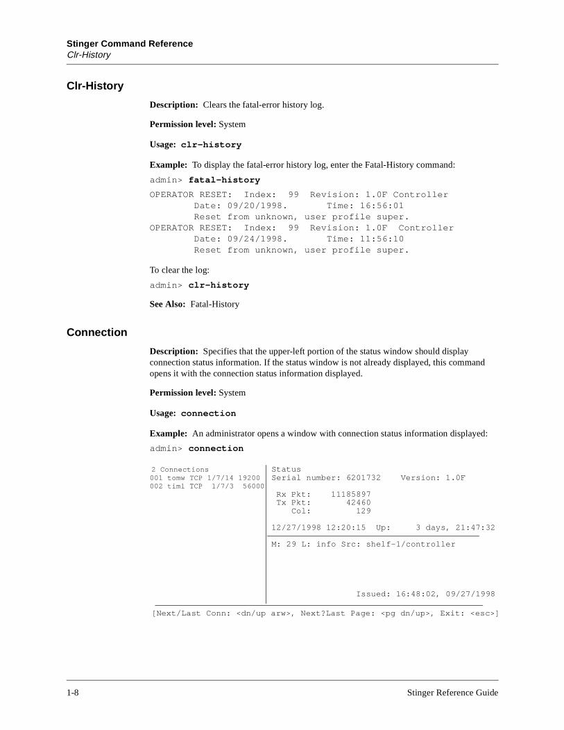
Description: Specifies that the upper-left portion of the status window should display connection status information. If the status window is not already displayed, this command opens it with the connection status information displayed.
Permission level: System
Usage: connection
Example: An administrator opens a window with connection status information displayed:
admin> connection
2 Connections StatusSerial number: 6201732 Version: 1.0F
Rx Pkt: 11185897 Tx Pkt: 42460 Col: 129
12/27/1998 12:20:15 Up: 3 days, 21:47:32
M: 29 L: info Src: shelf-1/controller
Issued: 16:48:02, 09/27/1998
[Next/Last Conn: <dn/up arw>, Next?Last Page: <pg dn/up>, Exit: <esc>]
001 tomw TCP 1/7/14 19200002 timl TCP 1/7/3 56000
1-8 Stinger Reference Guide

Stinger Command ReferenceDate
For each active connection, the displays includes a line that shows the user or station name, type of connection, shelf/line/channel on which the call was placed or received, and the bandwidth or baud rate. You can press the Down-Arrow key to scroll through the list of active connections.
To display a prompt below the status window, press the Escape key. To close the status window, enter the Status command:
admin> status
See Also: Line, List, Log, Status, View
Date
Description: Displays or sets the Stinger system date and time. The date and time are stored in the Timedate profile.
Permission level: Update
Usage: date [yymmddhhmm]
Example: To set the Stinger system date and time to noon, December 31, 1998:
admin> date 9812311200
Debug
Description: Enables or disables diagnostic output.
Permission level: Diagnostic
Usage: debug on | off
Option Description
yy A two-character representation of the current year
mm A two-character representation of the current month
dd A two-character representation of the current day
hh A two-character representation of the hour
mm A two-character representation of the minute
Syntax element Description
on Enables diagnostic output.
off Disables diagnostic output.
Stinger Reference Guide 1-9

Stinger Command ReferenceDelete
Example: To enable diagnostic output:
admin> debug onDiagnostic output enabledadmin> FRMAIN: Setting timer DCEFRMAIN: time 88121200, mkstatus type 1, seq (026,025)
Delete
Description: Permanently deletes a profile from local storage. Any flash space that was used by the profile becomes available to the system.
Permission level: Update
Usage: delete [-f] profile-type [profile-index]
Example: To delete the Connection profile previously created for Tom Lynch:
admin> delete conn tlynchDelete profile CONNECTION /tlynch? [y/n] yCONNECTION /tlynch deleted
See Also: Get, New, Read
Device
Description: Initiates a state change in a specified device. The device is specified by its interface address. This command is typically used to administratively up or down a device. For a list of devices supported by the Stinger, see the description of Device-Address.
Permission level: Diagnostic
Usage: device -d|-t|-u|-? interface_address
Syntax element Description
-f Delete without prompting for confirmation.
profile-type A type of profile, as listed by the Dir command.
profile-index The index of the specified profile type. Not all profile types require an index.
Option Description
-d Bring the specified device down.
-t Toggle debug output level.
-u Bring the specified device up.
-? Display a usage summary.
interface_address The interface address of the device, specified as shelf, slot, item number, and logical item number.
1-10 Stinger Reference Guide
Stinger Command ReferenceDir
Example: To administratively down device #24 in slot #3 on shelf #1:
admin> device -d {{1 3 24} 0}
See Also: Show, Slot
Dir
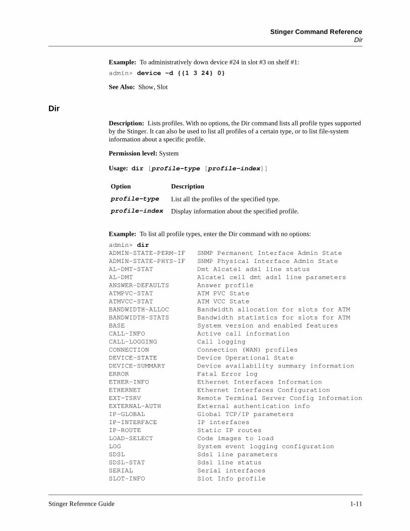
Description: Lists profiles. With no options, the Dir command lists all profile types supported by the Stinger. It can also be used to list all profiles of a certain type, or to list file-system information about a specific profile.
Permission level: System
Usage: dir [profile-type [profile-index]]
Example: To list all profile types, enter the Dir command with no options:
admin> dirADMIN-STATE-PERM-IF SNMP Permanent Interface Admin StateADMIN-STATE-PHYS-IF SNMP Physical Interface Admin StateAL-DMT-STAT Dmt Alcatel adsl line statusAL-DMT Alcatel cell dmt adsl line parametersANSWER-DEFAULTS Answer profileATMPVC-STAT ATM PVC StateATMVCC-STAT ATM VCC StateBANDWIDTH-ALLOC Bandwidth allocation for slots for ATMBANDWIDTH-STATS Bandwidth statistics for slots for ATMBASE System version and enabled featuresCALL-INFO Active call informationCALL-LOGGING Call loggingCONNECTION Connection (WAN) profilesDEVICE-STATE Device Operational StateDEVICE-SUMMARY Device availability summary informationERROR Fatal Error logETHER-INFO Ethernet Interfaces InformationETHERNET Ethernet Interfaces ConfigurationEXT-TSRV Remote Terminal Server Config InformationEXTERNAL-AUTH External authentication infoIP-GLOBAL Global TCP/IP parametersIP-INTERFACE IP interfacesIP-ROUTE Static IP routesLOAD-SELECT Code images to loadLOG System event logging configurationSDSL Sdsl line parametersSDSL-STAT Sdsl line statusSERIAL Serial interfacesSLOT-INFO Slot Info profile
Option Description
profile-type List all the profiles of the specified type.
profile-index Display information about the specified profile.
Stinger Reference Guide 1-11
Stinger Command ReferenceDircode
rth .
rds
S. To
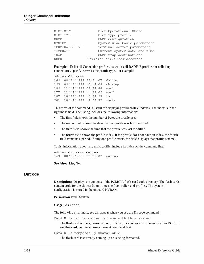
SLOT-STATE Slot Operational StateSLOT-TYPE Slot Type profileSNMP SNMP configurationSYSTEM System-wide basic parametersTERMINAL-SERVER Terminal server parametersTIMEDATE Current system date and timeTRAP SNMP trap destinationsUSER Administrative user accounts
Example: To list all Connection profiles, as well as all RADIUS profiles for nailed-up connections, specify conn as the profile type. For example:
admin> dir conn169 08/31/1998 22:21:07 dallas195 09/12/1998 10:14:08 chicago189 11/14/1998 09:34:44 nyc1177 11/14/1998 11:38:09 nyc2187 10/22/1998 15:34:53 la201 10/14/1998 14:29:32 sacto
This form of the command is useful for displaying valid profile indexes. The index is in the rightmost field. The listing includes the following information:
• The first field shows the number of bytes the profile uses.
• The second field shows the date that the profile was last modified.
• The third field shows the time that the profile was last modified.
• The fourth field shows the profile index. If the profile does not have an index, the foufield contains a period. If only one profile exists, the field displays that profile’s name
To list information about a specific profile, include its index on the command line:
admin> dir conn dallas169 08/31/1998 22:21:07 dallas
See Also: List, Get
Dircode
Description: Displays the contents of the PCMCIA flash-card code directory. The flash cacontain code for the slot cards, run-time shelf controller, and profiles. The system configuration is stored in the onboard NVRAM.
Permission level: System
Usage: dircode
The following error messages can appear when you use the Dircode command:
Card N is not formatted for use with this system
The flash card is blank, corrupted, or formatted for another environment, such as DOuse this card, you must issue a Format command first.
Card N is temporarily unavailable
The flash card is currently coming up or is being formatted.
1-12 Stinger Reference Guide
Stinger Command ReferenceDMTALDSLlines
Card N is unavailable
The flash card experienced an error and is inaccessible. Check that the card is inserted properly.
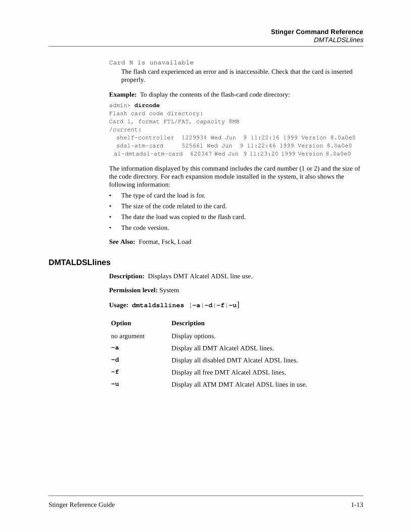
Example: To display the contents of the flash-card code directory:
admin> dircode
Flash card code directory:
Card 1, format FTL/FAT, capacity 8MB
/current:
shelf-controller 1229934 Wed Jun 9 11:22:16 1999 Version 8.0a0e0
sdsl-atm-card 525661 Wed Jun 9 11:22:46 1999 Version 8.0a0e0
al-dmtadsl-atm-card 620347 Wed Jun 9 11:23:20 1999 Version 8.0a0e0
The information displayed by this command includes the card number (1 or 2) and the size of the code directory. For each expansion module installed in the system, it also shows the following information:
• The type of card the load is for.
• The size of the code related to the card.
• The date the load was copied to the flash card.
• The code version.
See Also: Format, Fsck, Load
DMTALDSLlines
Description: Displays DMT Alcatel ADSL line use.
Permission level: System
Usage: dmtaldsllines [-a|-d|-f|-u]
Option Description
no argument Display options.
-a Display all DMT Alcatel ADSL lines.
-d Display all disabled DMT Alcatel ADSL lines.
-f Display all free DMT Alcatel ADSL lines.
-u Display all ATM DMT Alcatel ADSL lines in use.
Stinger Reference Guide 1-13
Stinger Command ReferenceDMTALDSLlines
he
ce is the nger
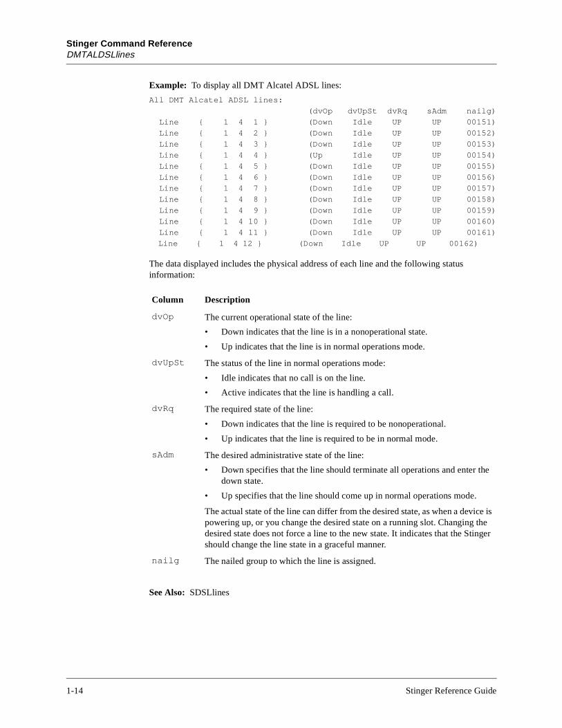
Example: To display all DMT Alcatel ADSL lines:
All DMT Alcatel ADSL lines:
(dvOp dvUpSt dvRq sAdm nailg)
Line { 1 4 1 } (Down Idle UP UP 00151)
Line { 1 4 2 } (Down Idle UP UP 00152)
Line { 1 4 3 } (Down Idle UP UP 00153)
Line { 1 4 4 } (Up Idle UP UP 00154)
Line { 1 4 5 } (Down Idle UP UP 00155)
Line { 1 4 6 } (Down Idle UP UP 00156)
Line { 1 4 7 } (Down Idle UP UP 00157)
Line { 1 4 8 } (Down Idle UP UP 00158)
Line { 1 4 9 } (Down Idle UP UP 00159)
Line { 1 4 10 } (Down Idle UP UP 00160)
Line { 1 4 11 } (Down Idle UP UP 00161)
Line { 1 4 12 } (Down Idle UP UP 00162)
The data displayed includes the physical address of each line and the following status information:
See Also: SDSLlines
Column Description
dvOp The current operational state of the line:
• Down indicates that the line is in a nonoperational state.
• Up indicates that the line is in normal operations mode.
dvUpSt The status of the line in normal operations mode:
• Idle indicates that no call is on the line.
• Active indicates that the line is handling a call.
dvRq The required state of the line:
• Down indicates that the line is required to be nonoperational.
• Up indicates that the line is required to be in normal mode.
sAdm The desired administrative state of the line:
• Down specifies that the line should terminate all operations and enter tdown state.
• Up specifies that the line should come up in normal operations mode.
The actual state of the line can differ from the desired state, as when a devipowering up, or you change the desired state on a running slot. Changing desired state does not force a line to the new state. It indicates that the Stishould change the line state in a graceful manner.
nailg The nailed group to which the line is assigned.
1-14 Stinger Reference Guide

Stinger Command ReferenceEther-Display
Ether-Display
Description: Displays the contents of Ethernet packets.
Permission level: Diagnostic
Usage: ether-display port# n
Example: To display Ethernet packet contents for port 0 in 12-octet sizes:
admin> ether-display 0 12
ETHER XMIT: 12 of 60 octets
10799E40: 08 00 20 75 80 6b 00 c0 7b 5e ad 3c .. u.k.. {^.<
ETHER RECV: 12 of 60 octets
1077D980: 00 c0 7b 5e ad 3c 00 80 c7 2f 27 ca ..{^.<.. ./’.
ETHER XMIT: 12 of 509 octets
1079A480: 00 80 c7 2f 27 ca 00 c0 7b 5e ad 3c .../’... {^.<
ETHER XMIT: 12 of 330 octets
1079AAC0: 08 00 20 75 80 6b 00 c0 7b 5e ad 3c .. u.k.. {^.<
ETHER RECV: 12 of 60 octets
1077DFD0: 00 c0 7b 5e ad 3c 08 00 20 75 80 6b ..{^.<.. u.k
ETHER XMIT: 12 of 451 octets
1079B100: 08 00 20 75 80 6b 00 c0 7b 5e ad 3c .. u.k.. {^.<
ETHER XMIT: 12 of 723 octets
1079B740: 00 20 af f8 0f 1d 00 c0 7b 5e ad 3c . ...... {^.<
ETHER XMIT: 12 of 84 octets
1078F580: 08 00 20 75 80 6b 00 c0 7b 5e ad 3c .. u.k.. {^.<
ETHER RECV: 12 of 60 octets
1077E620: 00 c0 7b 5e ad 3c 00 20 af f8 0f 1d ..{^.<. ....
ETHER XMIT: 12 of 238 octets
1078FBC0: 00 20 af f8 0f 1d 00 c0 7b 5e ad 3c . ...... {^.<
ETHER XMIT: 12 of 373 octets
10790200: 00 20 af f8 0f 1d 00 c0 7b 5e ad 3c . ...... {^.<
ETHER RECV: 12 of 60 octets
1077EC70: 00 c0 7b 5e ad 3c 00 20 af f8 0f 1d ..{^.<. ....
ETHER XMIT: 12 of 267 octets
10790840: 00 20 af f8 0f 1d 00 c0 7b 5e ad 3c . ...... {^.<
To stop displaying the Ethernet statistics, enter:
admin> ether-display 0 0
Note: You must set Debug On for Ether-Display to have any effect.
Syntax element Description
port# The Ethernet port on which the packets are received or transmitted. If you specify 0 (zero) for the port number, the Stinger displays all ports on the shelf.
n The number of octets to display in each Ethernet packet.
Stinger Reference Guide 1-15

Stinger Command ReferenceFatal-History
Fatal-History
Description: Displays the Stinger fatal-error log. Every time a fatal error occurs on the Stinger, it is logged to the fatal-error history log. Available flash space limits the number of entries in the log. You can clear the log with the Clr-History command.
Permission level: System
Usage: fatal-history
Example: To display the fatal-history log:
admin> fatal-historyOPERATOR RESET: Index: 99 Revision: 1.3Ap6 Shelf 1 Date: 09/20/1998. Time: 16:56:01 Reset from unknown, user profile super.OPERATOR RESET: Index: 99 Revision: 1.3Ap6 Shelf 9 Date: 09/24/1998. Time: 11:56:10 Reset from unknown, user profile super.
See Also: Clr-History
Format
Description: Formats a PCMCIA flash card, preparing it for use in the Stinger. You must format the card before you can use the Load command to load code.
Permission level: Code
Usage: format [-f] device
The following error messages can appear when you use the Format command:
error: flash card N is not present
No flash card is detected in the specified slot (1 or 2).
error: flash card N is unavailable
The flash card in the specified slot is already being formatted, is just coming up, or is in an error condition.
error: flash card N is write-protected
The write-protect switch is set on the card in the specified slot (1 or 2).
error: flash card N is currently in use
One or more images on the flash card are currently in use (being read by a slot card in LOAD state or being written as part of a code download).
Syntax element Description
-f Force format without asking for verification.
device The name of the flash card to be formatted. The following are valid names:• [flash-card-]1• [flash-card-]2
Note that device names may be abbreviated as 1 and 2.
1-16 Stinger Reference Guide

Stinger Command ReferenceFsck
Example: After inserting a PCMCIA flash card in the second (rightmost) slot on the shelf controller, you would format it as follows:
admin> format flash-card-2format will erase existing card 2 data; confirm: [y/n] y
See Also: Dircode, Fsck, Load
Fsck
Description: Audits inconsistent file conditions (which can include file contents) on a PCMCIA flash card. For each file found, the command displays the type-name, type-number, decimal and hex byte counts, date written to flash, and whether blocks that were in use were allocated to a file. Any detected errors are reported. No errors are fixed.
Permission level: Code
Usage: fsck [-b -c -v] device
Syntax element Significance
-b Try to ignore bad magic. Each flash card file system contains two direc-tory blocks: an in-use block and an empty block used when deleting information. Both directory blocks contain a magic identifier, which indi-cates that they are indeed directory blocks. A candidate directory block is one that is missing the magic identifier but contains information that can be interpreted as directory-block information. If Fsck finds no valid directory block but does find a candidate directory block, this option causes it to ignore the bad magic and go ahead and use the candidate directory block anyway. This option allow the file system to be used nor-mally until the next reboot, assuming that the Fsck command found no other errors.
-c Do not check file contents. By default, Fsck checks the file contents for validity, which involves opening and reading every file, checking the file header, verifying the data length and CRC value, and performing other functions. This option causes Fsck to check only the file-system format.
-v Display verbose messages, including the number of blocks used, a block list, and (unless the –c option is specified) various information about the files found. See the example below.
device The name of the flash card to be checked. The following are valid names:• [flash-card-]1
• [flash-card-]2
Note that device names may be abbreviated as 1 and 2.
Stinger Reference Guide 1-17

Stinger Command ReferenceGet
file
om-
Example: To run a file-system check of the card named flash-card-1:
admin> fsck 1
Volume Stats:
Block Size: 512 (typical: 512)
Blocks Per Cluster: 4 (typical: 1, may be powers of 2 up to 16)
Reserved Blocks: 1 (typical: 1, but may be 0 - hundreds)
Number of FATs: 2 (must be 2)
Number of Root Directory Entries: 128 (typically between 32 and 224)
Total Blocks: 13824
Media Descriptor: f0 (ignored)
Volume Info calculated from values above:
Blocks Per Fat: 11
Fat Start Block: 1
Root Dir Start Block: 23
Data Start Block: 31
Number of Root Dir Blocks: 8
Number of Clusters: 3448
FAT Type: Fat12
Cluster Usage
Usable Clusters: 3446
Free Clusters: 2284
Clusters lost during interrupted writes: 0
Other reserved clusters: 1158
See Also: Dircode, Format, Load
Get
Description: Displays the contents of a profile or subprofile, but does not make it writable. Only the working profile can be modified. For information about reading a profile into the edit buffer to make it the working profile, see “Read” on page 1-46.
The Get command recognizes the period character (.) as a shorthand for the working pro(the profile in the edit buffer).
Permission level: System
Usage: get profile-type [profile-index][[sub-profile][param-name [param-index]]
Syntax element Description
profile-type The type of profile to be displayed, which might require an index aswell. A period represents the working profile (the profile in the edit buffer).
profile-index The profile index (the name or address that distinguishes a profile from others of the same type). To see profile indexes, use the Dir cmand.
sub-profile A subprofile within the specified profile.
1-18 Stinger Reference Guide
Stinger Command ReferenceGet
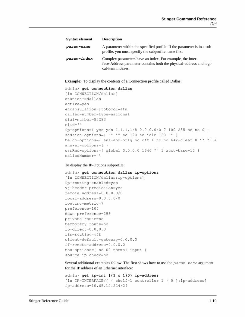
Example: To display the contents of a Connection profile called Dallas:
admin> get connection dallas[in CONNECTION/dallas]station*=dallasactive=yesencapsulation-protocol=atmcalled-number-type=nationaldial-number=85283clid=""ip-options={ yes yes 1.1.1.1/8 0.0.0.0/0 7 100 255 no no 0 +session-options={ "" "" no 120 no-idle 120 "" }telco-options={ ans-and-orig no off 1 no no 64k-clear 0 "" "" +answer-options={ }usrRad-options={ global 0.0.0.0 1646 "" 1 acct-base-10 }calledNumber=""
To display the IP-Options subprofile:
admin> get connection dallas ip-options[in CONNECTION/dallas:ip-options]ip-routing-enabled=yesvj-header-prediction=yesremote-address=0.0.0.0/0local-address=0.0.0.0/0routing-metric=7preference=100down-preference=255private-route=notemporary-route=noip-direct=0.0.0.0rip=routing-offclient-default-gateway=0.0.0.0if-remote-address=0.0.0.0tos-options={ no 00 normal input }source-ip-check=no
Several additional examples follow. The first shows how to use the param-name argument for the IP address of an Ethernet interface:
admin> get ip-int {{1 c 1}0} ip-address[in IP-INTERFACE/{ { shelf-1 controller 1 } 0 }:ip-address] ip-address=10.65.12.224/24
param-name A parameter within the specified profile. If the parameter is in a sub-profile, you must specify the subprofile name first.
param-index Complex parameters have an index. For example, the Inter-face-Address parameter contains both the physical-address and logi-cal-item indexes.
Syntax element Description
Stinger Reference Guide 1-19
Stinger Command ReferenceGet
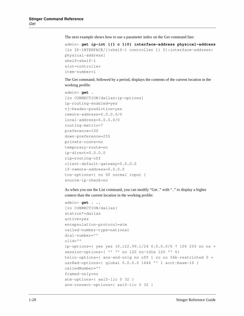
The next example shows how to use a parameter index on the Get command line:
admin> get ip-int {{1 c 1}0} interface-address physical-address
[in IP-INTERFACE/{{shelf-1 controller 1} 0}:interface-address:
physical-address]
shelf=shelf-1
slot=controller
item-number=1
The Get command, followed by a period, displays the contents of the current location in the working profile:
admin> get .
[in CONNECTION/dallas:ip-options]
ip-routing-enabled=yes
vj-header-prediction=yes
remote-address=0.0.0.0/0
local-address=0.0.0.0/0
routing-metric=7
preference=100
down-preference=255
private-route=no
temporary-route=no
ip-direct=0.0.0.0
rip=routing-off
client-default-gateway=0.0.0.0
if-remote-address=0.0.0.0
tos-options={ no 00 normal input }
source-ip-check=no
As when you use the List command, you can modify “Get .” with “..” to display a higher
context than the current location in the working profile:
admin> get . ..
[in CONNECTION/dallas]
station*=dallas
active=yes
encapsulation-protocol=atm
called-number-type=national
dial-number=""
clid=""
ip-options={ yes yes 10.122.99.1/24 0.0.0.0/0 7 100 255 no no +
session-options={ "" "" no 120 no-idle 120 "" 0}
telco-options={ ans-and-orig no off 1 no no 56k-restricted 0 +
usrRad-options={ global 0.0.0.0 1646 "" 1 acct-base-10 }
calledNumber=""
framed-only=no
atm-options={ aal5-llc 0 32 }
atm-connect-options={ aal5-llc 0 32 }
1-20 Stinger Reference Guide
Stinger Command ReferenceHelp
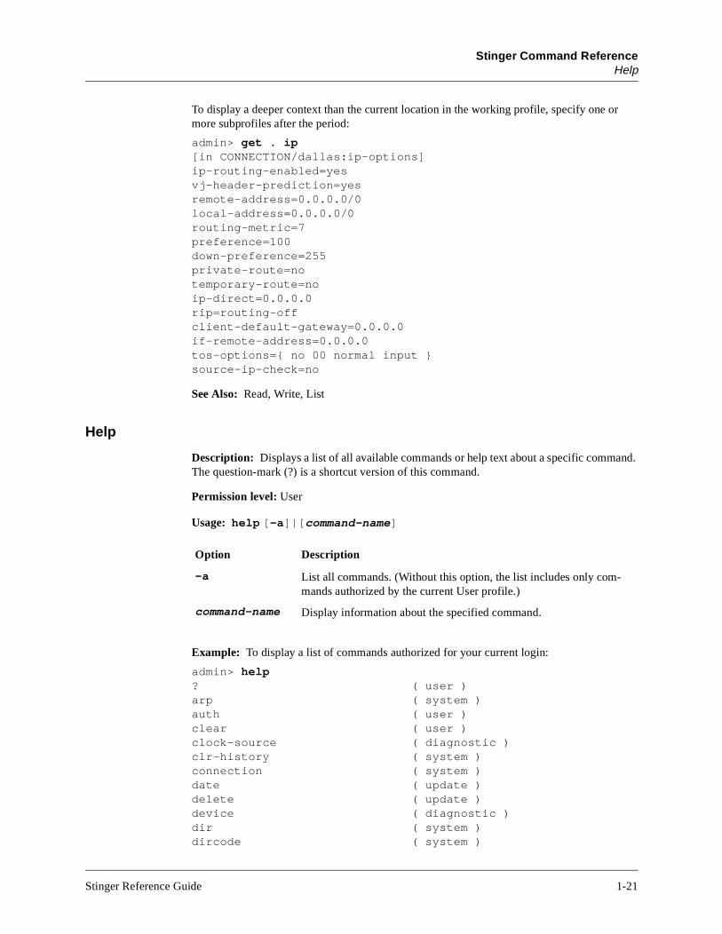
To display a deeper context than the current location in the working profile, specify one or more subprofiles after the period:
admin> get . ip[in CONNECTION/dallas:ip-options]ip-routing-enabled=yesvj-header-prediction=yesremote-address=0.0.0.0/0local-address=0.0.0.0/0routing-metric=7preference=100down-preference=255private-route=notemporary-route=noip-direct=0.0.0.0rip=routing-offclient-default-gateway=0.0.0.0if-remote-address=0.0.0.0tos-options={ no 00 normal input }source-ip-check=no
See Also: Read, Write, List
Help
Description: Displays a list of all available commands or help text about a specific command. The question-mark (?) is a shortcut version of this command.
Permission level: User
Usage: help [-a]|[command-name]
Example: To display a list of commands authorized for your current login:
admin> help? ( user )arp ( system )auth ( user )clear ( user )clock-source ( diagnostic )clr-history ( system )connection ( system )date ( update )delete ( update )device ( diagnostic )dir ( system )dircode ( system )
Option Description
–a List all commands. (Without this option, the list includes only com-mands authorized by the current User profile.)
command-name Display information about the specified command.
Stinger Reference Guide 1-21

Stinger Command ReferenceIf-Admin
h a card ets, ilures.
ether-display ( diagnostic )fatal-history ( system )format ( code )get ( system )help ( user )if-admin ( diagnostic )line ( system )[More? <ret>=next entry, <sp>=next page, <^C>=abort]
To display help text about the Dir command, for example:
admin> help dirdir list all profile typesdir profile-type list all profiles of the specified typedir profile-type profile-index list the specified profile instance
Dependencies: The current security level is set by the current User profile and determines which commands are displayed in response to this command. If the current User profile does not have sufficient privileges to execute a command, the command is not displayed unless you specify the -a option. Commands with the User security level are always displayed. For detailed information, see “Auth” on page 1-6.
If-Admin
Description: Displays information about or changes the state of an SNMP interface. Eacdevice in the system has a unique SNMP interface number assigned to the device whenis installed. Interface numbers are stored in NVRAM, which is not affected by system resso a physical device keeps the same interface number across system resets or power fa
Permission level: Diagnostic
Usage: if-admin -a|-d interface|-l|-u interface|-r interface|-?
Option Description
-a List available SNMP interface numbers.
-d interface Administratively down a specified SNMP interface
-l List SNMP interface/device address mappings.
-u interface Administratively bring up a specified SNMP interface.
-r interface Reset an SNMP interface.
-? Display a usage summary.
1-22 Stinger Reference Guide

Stinger Command ReferenceIProute
Example: To display a list of all SNMP interface numbers assigned by the system, specify the -l option:
admin> if-admin -lSNMP-IF DEVICE ADDRESS 101 - { 1 11 32 } 1 - { 1 17 1 } 102 - { 1 11 33 } 2 - { 1 3 1 } 103 - { 1 11 34 } 3 - { 1 3 2 } 104 - { 1 11 35 } 4 - { 1 3 3 } 105 - { 1 11 36 } 5 - { 1 3 4 } 106 - { 1 11 37 } 6 - { 1 3 5 } 107 - { 1 11 38 } 7 - { 1 3 6 } 108 - { 1 11 39 } 8 - { 1 3 7 }[More <ret>=next entry, <sp>=next page, <^C>=abort]
To bring up SNMP interface number 111:
admin> if-admin -u 111interface 111 state change forced
IProute
Description: Enables you to manually add or delete IP routes. Changes to the routing table do not persist across system resets.
Permission level: System
Usage: iproute add|delete
Syntax element Description
add Add an IP route to the routing table.
delete Delete an IP route from the routing table.
Stinger Reference Guide 1-23

Stinger Command ReferenceIProute
metric
s not If you
route.
nger.
nd.
inger
n
Adding a static IP route to the routing table
To add a static IP route to the unit’s routing table, use the IProute Add command.
iproute add dest_IPaddr[/subnet_mask] gateway_IPaddr[/subnet_mask] [pref] [metric]
For example, consider the following command:
admin> iproute add 10.1.2.0/24 10.0.0.3/24 1
It adds a route to the 10.1.2.0 network, through the IP router located at 10.0.0.3/24. The to the route is 1 (one hop away).
If you try to add a route to a destination that is already in the routing table, the Stinger doereplace the existing route unless it has a higher metric than the route you attempt to add.get the message Warning: a better route appears to exist, the Stinger has rejected your attempt to add a route. Note that RIP updates can change the metric for the
Note: Any routes you add with the IProute Add command are lost when you reset the Sti
Deleting a static IP route from the routing table
To remove a static IP route from the unit’s routing table, enter the IProute Delete comma
iproute delete dest_IPaddr/subnet_mask [gateway_IPaddr[/subnet_mask]]
For example, the following command removes the route to the 10.1.2.0 network:
admin> iproute delete 10.1.2.0/24 10.0.0.3/24
Note: RIP updates can add back any route you remove with IProute Delete. Also, the Strestores all routes listed in the IP-Route profile after a system reset.
Syntax element Description
dest_IPaddr/subnet_mask Destination network address and subnet mask (ibits). The default is 0.0.0.0/0.
gateway_IPaddr/subnet_mask IP address of the router that can forward packetsto the destination network, and subnet mask (in bits). The default is 0.0.0.0.
pref Route preference. The default is 100.
metric Virtual hop count of the route. You can enter a value between 1 and 15. The default is 1.
1-24 Stinger Reference Guide

Stinger Command ReferenceLine
ter
Line
Description: Specifies that the upper-right or lower-right portion of the status window (or both) should display line and channel status information. If the status window is not already displayed, this command opens it with the connection status information displayed.
Permission level: System
Usage: line all|enabled top|bottom
Example: To display line status information in the upper part of the status window:
admin> line top
Line status information includes the following identifiers and codes:
• A line identifier in shelf/slot/line format.
• A two-character code indicating the line’s link status.
• A single-character code indicating channel status. For an SS7 data trunk, this characcode is always 7.
Option Description
all Display status information about all lines.
enabled Display status information only about enabled lines.
top Display line status in the upper portion of the status window.
bottom Display line status in the lower portion of the status window (the default).
SanFran+ 1/13/8 RA I........ ........ ......
M: 48 L: info Src: shelf-1/controller
Issued: 16:48:02, 09/27/1998
[Next/Last Conn <dn/up arw>, Next?Last Page: <pg dn/up>, Exit: <esc>]
2 Connections001 tomw TCP 1/7/14 19200002 timl TCP 1/7/3 56000 Berkeley 1/01/04 RA N........ ........ ......
1/01/05 RA T........ ........ ...... Clevela+ 1/01/01 RA T........ ........ ...... Oakland 1/01/02 RA S........ ........ ......
Stinger Reference Guide 1-25
Stinger Command ReferenceLine
g ation
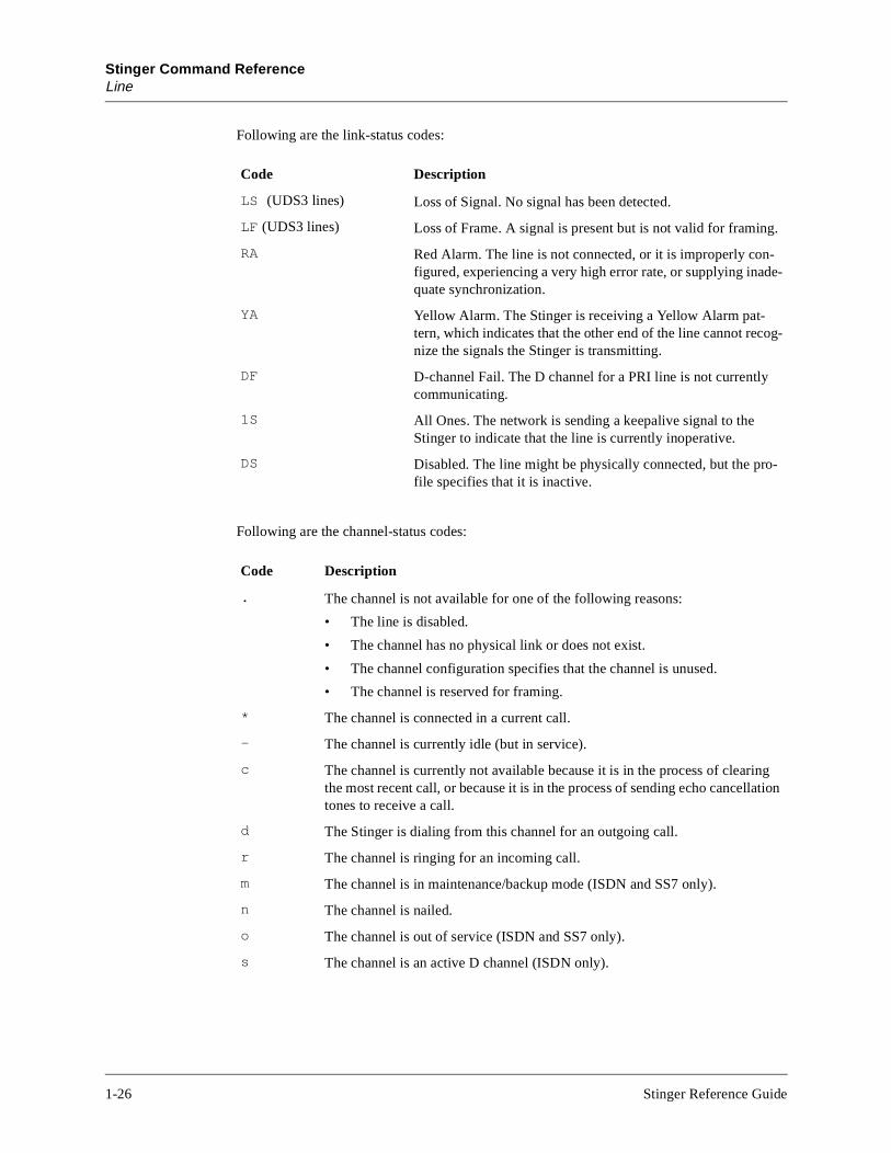
Following are the link-status codes:
Following are the channel-status codes:
Code Description
LS (UDS3 lines) Loss of Signal. No signal has been detected.
LF (UDS3 lines) Loss of Frame. A signal is present but is not valid for framing.
RA Red Alarm. The line is not connected, or it is improperly con-figured, experiencing a very high error rate, or supplying inade-quate synchronization.
YA Yellow Alarm. The Stinger is receiving a Yellow Alarm pat-tern, which indicates that the other end of the line cannot recog-nize the signals the Stinger is transmitting.
DF D-channel Fail. The D channel for a PRI line is not currently communicating.
1S All Ones. The network is sending a keepalive signal to the Stinger to indicate that the line is currently inoperative.
DS Disabled. The line might be physically connected, but the pro-file specifies that it is inactive.
Code Description
. The channel is not available for one of the following reasons:
• The line is disabled.
• The channel has no physical link or does not exist.
• The channel configuration specifies that the channel is unused.
• The channel is reserved for framing.
* The channel is connected in a current call.
- The channel is currently idle (but in service).
c The channel is currently not available because it is in the process of clearinthe most recent call, or because it is in the process of sending echo cancelltones to receive a call.
d The Stinger is dialing from this channel for an outgoing call.
r The channel is ringing for an incoming call.
m The channel is in maintenance/backup mode (ISDN and SS7 only).
n The channel is nailed.
o The channel is out of service (ISDN and SS7 only).
s The channel is an active D channel (ISDN only).
1-26 Stinger Reference Guide
Stinger Command ReferenceList
xt.
le,
gi-
,
To display a prompt below the status window, press the Escape key. To scroll through the list of lines, press the Up-Arrow or Down-Arrow key, or to page up or down through the lines, press the Page Up or Page Dn key. To close the status window:
admin> status
See Also: Connection, Log, Status, View
List
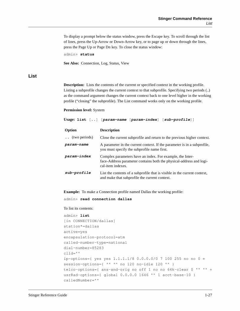
Description: Lists the contents of the current or specified context in the working profile. Listing a subprofile changes the current context to that subprofile. Specifying two periods (..) as the command argument changes the current context back to one level higher in the working
profile (“closing” the subprofile). The List command works only on the working profile.
Permission level: System
Usage: list [..] [param-name [param-index] [sub-profile]]
Example: To make a Connection profile named Dallas the working profile:
admin> read connection dallas
To list its contents:
admin> list
[in CONNECTION/dallas]
station*=dallas
active=yes
encapsulation-protocol=atm
called-number-type=national
dial-number=85283
clid=""
ip-options={ yes yes 1.1.1.1/8 0.0.0.0/0 7 100 255 no no 0 +
session-options={ "" "" no 120 no-idle 120 "" }
telco-options={ ans-and-orig no off 1 no no 64k-clear 0 "" "" +
usrRad-options={ global 0.0.0.0 1646 "" 1 acct-base-10 }
calledNumber=""
Option Description
.. (two periods) Close the current subprofile and return to the previous higher conte
param-name A parameter in the current context. If the parameter is in a subprofiyou must specify the subprofile name first.
param-index Complex parameters have an index. For example, the Inter-face-Address parameter contains both the physical-address and local-item indexes.
sub-profile List the contents of a subprofile that is visible in the current contextand make that subprofile the current context.
Stinger Reference Guide 1-27

Stinger Command ReferenceList
To list the IP-Options subprofile:
admin> list ip-options[in CONNECTION/dallas:ip-options]ip-routing-enabled=yesvj-header-prediction=yesremote-address=0.0.0.0/0local-address=0.0.0.0/0routing-metric=7preference=100down-preference=255private-route=notemporary-route=noip-direct=0.0.0.0rip=routing-offclient-default-gateway=0.0.0.0if-remote-address=0.0.0.0tos-options={ no 00 normal input }source-ip-check=no
To return to the top-level context of the profile:
admin> list ..
To use the List command to display the Telco-Options subprofile:
admin> list .. telco[in CONNECTION/dallas:telco-options]answer-originate=ans-and-orignailed-groups=1force-56kbps=nodata-service=56k-restrictedcall-by-call=0billing-number=""transit-number=""
The List command works only on the working profile. To make an existing profile the working profile, use the Read command. When you create a new profile, it becomes the working profile automatically.
See Also: Dir, Get, Read, New, Set, Write
1-28 Stinger Reference Guide
Stinger Command ReferenceLoad
to
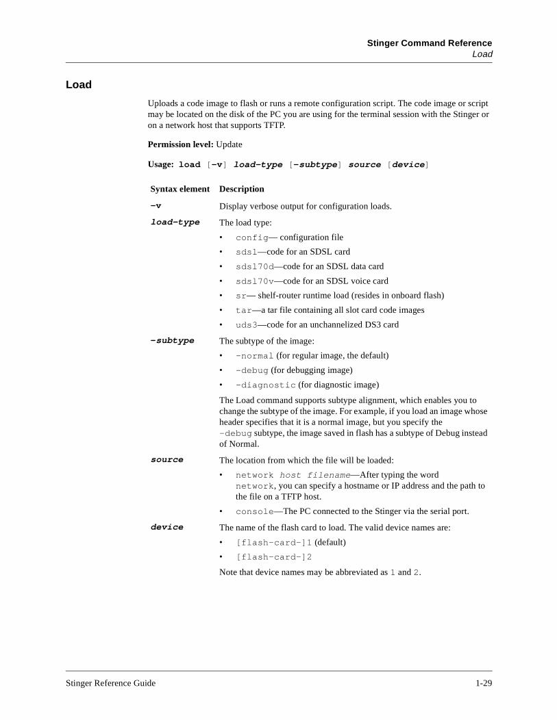
Load
Uploads a code image to flash or runs a remote configuration script. The code image or script may be located on the disk of the PC you are using for the terminal session with the Stinger or on a network host that supports TFTP.
Permission level: Update
Usage: load [-v] load-type [-subtype] source [device]
Syntax element Description
-v Display verbose output for configuration loads.
load-type The load type:
• config— configuration file
• sdsl—code for an SDSL card
• sdsl70d—code for an SDSL data card
• sdsl70v—code for an SDSL voice card
• sr— shelf-router runtime load (resides in onboard flash)
• tar—a tar file containing all slot card code images
• uds3—code for an unchannelized DS3 card
-subtype The subtype of the image:
• –normal (for regular image, the default)
• –debug (for debugging image)
• –diagnostic (for diagnostic image)
The Load command supports subtype alignment, which enables you to change the subtype of the image. For example, if you load an image whose header specifies that it is a normal image, but you specify the –debug subtype, the image saved in flash has a subtype of Debug instead of Normal.
source The location from which the file will be loaded:
• network host filename—After typing the word network, you can specify a hostname or IP address and the paththe file on a TFTP host.
• console—The PC connected to the Stinger via the serial port.
device The name of the flash card to load. The valid device names are:
• [flash-card-]1 (default)
• [flash-card-]2
Note that device names may be abbreviated as 1 and 2.
Stinger Reference Guide 1-29

Stinger Command ReferenceLoad
rd or a s the
Example: To load a configuration file named unit.cfg from a network host 10.8.7.2 to flash-card-1:
admin> load config network 10.8.7.2 /unit.cfg
To load the unitrel.tar file from a network host named host1:
admin> load tar net host1 unitrel.tar
If the system terminates the process of loading a tar file, one of the following messages might appear:
load aborted: not a tar image
load aborted: a tar image, inconsistent with the specified load-type.
load aborted: invalid/unknown image header.
load aborted: mismatched image for the specified load-type.
load aborted: invalid image, unsupported by load tar command.
The Load command supports type checking to verify that the load type specified on the command line matches the image header. The above messages indicate that the type checking process discovered inconsistencies between the load type and the image header. Check your command line. If necessary, download the tar file again.
The following warning message does not terminate the Load, but indicates that you are not loading the most recent software version:
load: warning: old image header version detected, load continued...
Finally, the following error messages can also appear when you use the Load command:
load: error: flash card write failed: card full
There is no space to load software on the flash card.
load: error: specified flash card not present
No flash card is detected in the specified slot (1 or 2).
load: error: specified flash card not formatted
A Format command is required before loading the software.
load: error: specified flash card has obsolete format
A Format is required because a 1.3A file system was detected.
load: error: specified flash card is write-protected
The flash card’s write-protect switch is set.
load: error: specified flash image is currently in use
A slot card in the LOAD state is currently accessing the flash card.
Dependencies: You can set parameters in the Load-Select profile to specify which slot-caimages to load to flash when you use a Load Tar command. An explicit Load command fparticular card type overrides the settings in the Load-Select profile. The Load commandsupports type checking to verify that the load type specified on the command line matcheimage header.
See Also: Dircode, Format, Fsck, Save
1-30 Stinger Reference Guide
Stinger Command ReferenceLog
Log
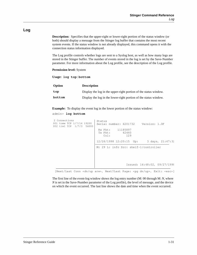
Description: Specifies that the upper-right or lower-right portion of the status window (or both) should display a message from the Stinger log buffer that contains the most recent system events. If the status window is not already displayed, this command opens it with the connection status information displayed.
The Log profile controls whether logs are sent to a Syslog host, as well as how many logs are stored in the Stinger buffer. The number of events stored in the log is set by the Save-Number parameter. For more information about the Log profile, see the description of the Log profile.
Permission level: System
Usage: log top|bottom
Example: To display the event log in the lower portion of the status window:
admin> log bottom
The first line of the event-log window shows the log entry number (M: 00 through M: N, where N is set in the Save-Number parameter of the Log profile), the level of message, and the device on which the event occurred. The last line shows the date and time when the event occurred.
Option Description
top Display the log in the upper-right portion of the status window.
bottom Display the log in the lower-right portion of the status window.
StatusSerial number: 6201732 Version: 1.0F
Rx Pkt: 11185897 Tx Pkt: 42460 Col: 129
12/26/1998 12:20:15 Up: 3 days, 21:47:32
M: 29 L: info Src: shelf-1/controller
Issued: 16:48:02, 09/27/1998
[Next/Last Conn <dn/up arw>, Next?Last Page: <pg dn/up>, Exit: <esc>]
2 Connections001 tomw TCP 1/7/14 19200002 timl TCP 1/7/3 56000
Stinger Reference Guide 1-31

Stinger Command ReferenceLog
The message levels are as follows:
The text of the most recent message is displayed in the middle of the window. You can press the Up-Arrow key to see previous messages, and return to more recent messages by pressing the Down-Arrow key.
Following are some sample informational messages:
Level Description
emergency A failure or major error has occurred, and normal operation is doubtful.
alert A failure or major error has occurred, but normal operation can probably continue.
critical An interface has gone down, or there has been a security error.
error Something that should not occur has occurred.
warning Something out of the ordinary, such as a login failure due to an invalid user name or password, has happened in otherwise normal operations.
notice Something of interest, such as a link going up or down, has happened dur-ing normal operation.
info A change in state or status was noticed. Such messages are not of general interest.
debug The message is of interest only if you are debugging a configuration.
Informational message Description
Incoming call A call has been received but not yet routed.
Outgoing call The Stinger has dialed a call.
Added Bandwidth The Stinger has added bandwidth to an active call.
Ethernet up The Ethernet interface has been initialized and is running.
Call Terminated An active call was disconnected normally, although not necessar-ily by operator command.
Removed Bandwidth The Stinger has removed bandwidth from an active call.
RADIUS config error
The Stinger has detected an error in the configuration of a RADIUS user profile.
Requested Service Not Authorized
This message appears in the terminal server interface if the user requests a service not authorized by the RADIUS server.
1-32 Stinger Reference Guide

Stinger Command ReferenceNetstat
Following are some sample warning messages:
Press the Escape key to display a prompt below the status window. Then, to close the status window, enter the Status command:
admin> status
See Also: Connection, Line, Status, View
Netstat
Description: Displays the Stinger interface and routing tables, protocol statistics, and active sockets.
Permission level: System
Usage: netstat [-i] [-r[host]] [?] [-n | -d][-s identifiers][-z]
Warning message Description
Busy The phone number was busy when the call was dialed.
No connection The remote end did not answer when the call was dialed.
Network problem
The call setup was faulty because of problems in the WAN or in the Line profile configuration. The D channel might be getting an error message from the switch, or the telco might be experiencing a problem.
Call disconnected
The call has ended unexpectedly.
Far end hung up
The remote end terminated the call normally.
Incoming glare
The Stinger could not place a call because it saw an incoming glare sig-nal from the switch. If you receive this error message, you have proba-bly selected incorrect Line profile parameters. Check the Robbed-Bit-Mode setting.
Call Refused An incoming call could not be connected.
Option Description
no arguments Display UDP and TCP statistics.
-i Display the IP interface table.
-r host Display the IP routing table. You can specify a hostname after the –r option to display the routing table entry for that host.
-? Display a usage summary.
-n Display numeric addresses rather than symbolic names (the default).
-d Display symbolic names rather than numeric addresses.
Stinger Reference Guide 1-33

Stinger Command ReferenceNetstat
Displaying UDP and TCP statistics
To display both UDP and TCP statistics, do not specify any options. For example:
admin> netstat
udp:
-Socket- Local Port InQLen InQMax InQDrops Total Rx
1/c 0 1023 0 1 0 0
1/c 1 route 0 0 0 25
1/c 2 echo 0 32 0 0
1/c 3 ntp 0 32 0 1
1/c 4 1022 0 128 0 0
1/c 5 snmp 0 128 0 0
1/1 0 1 0 256 0 0
1/1 1 1018 0 128 0 0
1/3 0 3 0 256 0 0
1/3 1 1021 0 128 0 0
1/5 0 5 0 256 0 0
1/5 1 1020 0 128 0 0
tcp:
Socket Local Remote State
1/c 0 *.23 *.* LISTEN
1/c 1 10.2.3.114.23 15.5.248.121.44581 ESTABLISHED
The display contains the following information:
-s identifiers
Display protocol statistics. If no identifiers follow the –s option, all proto-col statistics are printed. If you specify one or more identifiers, they deter-mine the type of protocol statistics to display. The valid identifiers are udp , tcp , icmp , ip , igmp , and mcast .
-z Display Zombie routes created for RIP. Zombie routes are those that have been deleted from the main routing table and are advertised with an infinite metric (16) for a period of 2 minutes to cause neighboring router to flush this route from their tables.
Option Description
Column Description
Socket The shelf, slot, and socket corresponding to a local UDP or TCP port.
Local Port
The port on which the Stinger is listening for UDP packets.
InQLen The number of packets in the input queue for the socket. The packets are wait-ing to be processed.
InQMax The maximum number of packets that can reside in the input queue for the socket. A value of 0 (zero) means no limit. The Stinger drops excess packets.
InQDrops The number of packets dropped from the input queue because the value of InQ-Max was reached.
Total Rx The total number of packets received on the socket, including dropped packets.
1-34 Stinger Reference Guide

Stinger Command ReferenceNetstat
s the
e
e
d it
For UDP, Netstat reports the following services:
Local The local IP address and port for a TCP session. For example, in the value 10.2.3.114.23, 10.2.3.114 specifies the IP address and 23 specifies the port for a TCP session. If the address portion contains only an asterisk (*), the Stinger is listening for the start of a TCP session.
Remote The remote IP address and port for a TCP session. For example, in the value 15.5.248.121.44581, 15.5.248.121 specifies the IP address and 44581 specifies the port for a TCP session. If the specification contains only asterisks (*.*), the Stinger is listening for the start of a TCP session.
State The state of the session. The possible state values are:
CLOSED—The socket is not in use.
LISTEN—The socket is listening for incoming connections. Note that nosession is associated with the LISTEN state, because this state precedeestablishment of a TCP session.
SYN_SENT—The socket is trying to establish a connection.
SYN_RECEIVED—The connection is being synchronized.
ESTABLISHED—The connection is established.
CLOSE_WAIT—The remote side has shut down the connection, and thStinger is waiting for the socket to close.
FIN_WAIT_1—The socket is closed, and the Stinger is shutting down thconnection.
CLOSING—The socket is closed. The Stinger is waiting for acknowledgment that the remote end has shut down.
LAST_ACK—The remote end has shut down and closed the socket, anis waiting for an acknowledgment from the Stinger.
FIN_WAIT_2—The socket is closed, and the Stinger is waiting for the remote end to shut down the connection.
TIME_WAIT—The socket is closed, and the Stinger is waiting for a remote-shutdown retransmission.
Service UDP port number
Route 520
Echo 7
NTP 123
SNMP 161
SNMPTrap 162
Column Description
Stinger Reference Guide 1-35

Stinger Command ReferenceNetstat
n
For TCP, Netstat reports the following services:
Displaying the interface table
The Stinger interface table shows the address of each interface. To display the Stinger interface table, specify the -i option:
admin> netstat -i
The entries in the interface table associated with the Stinger Ethernet interfaces use the following naming convention:
ie[shelf]-[slot]-[item]
For example, the following output shows a four-port Ethernet card in slot 13:
Name MTU Net/Dest Address Ipkts Ierr Opkts Oerr
ie0 1500 12.65.212.0/24 12.65.212.227 107219 0 54351 0
lo0 1500 127.0.0.1/32 127.0.0.1 4867 0 4867 0
rj0 1500 127.0.0.2/32 127.0.0.2 0 0 0 0
bh0 1500 127.0.0.3/32 127.0.0.3 0 0 0 0
wan4 1500 10.122.99.1 - 0 0 0 0
ie1-12-1 1500 11.168.6.0/24 11.168.6.227 430276 651 0 0
ie1-12-2 1500 10.122.72.0/24 10.122.72.1 0 0 0 3144
ie1-12-3 1500 10.122.73.0/24 10.122.73.1 0 0 3142 0
ie1-12-4 1500 10.122.74.0/24 10.122.74.1 0 0 3141 0
The columns in the interface table contain the following information:
Service TCP port number
Telnet 23
Column Description
Name The name of the interface:
• ie0 or ie[shelf]-[slot]-[item] is an Ethernet interface.
• lo0 is the loopback interface.
• rj0 is the reject interface, used in network summarization.
• bh0 is the blackhole interface, used in network summarization.
• wanN is a WAN connection, entered as it becomes active.
• wanabe indicates an inactive RADIUS dialout profile.
MTU (Maximum Transmission Unit) The maximum packet size allowed othe interface.
Net/Dest The network or the target host this interface can reach.
Address The address of this interface.
Ipkts The number of packets received.
Ierr The number of packets that contain errors.
1-36 Stinger Reference Guide
Stinger Command ReferenceNetstat
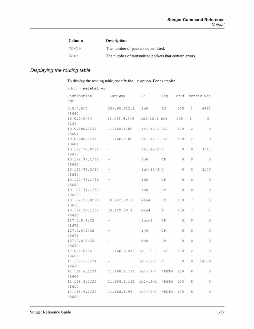
Displaying the routing table
To display the routing table, specify the -r option. For example:
admin> netstat -r
Destination Gateway IF Flg Pref Metric Use
Age
0.0.0.0/0 206.65.212.1 ie0 SG 100 1 4891
48630
10.0.0.0/24 11.168.6.249 ie1-12-1 RGT 100 3 0
9236
10.0.100.0/24 11.168.6.86 ie1-12-1 RGT 100 2 0
48601
10.0.200.0/24 11.168.6.86 ie1-12-1 RGT 100 2 0
48601
10.122.72.0/24 - ie1-12-2 C 0 0 3141
48630
10.122.72.1/32 - lo0 CP 0 0 0
48630
10.122.73.0/24 - ie1-12-3 C 0 0 3140
48630
10.122.73.1/32 - lo0 CP 0 0 0
48630
10.122.74.1/32 - lo0 CP 0 0 0
48630
10.122.99.0/24 10.122.99.1 wan4 SG 100 7 0
48630
10.122.99.1/32 10.122.99.1 wan4 S 100 7 1
48630
127.0.0.1/32 - local CP 0 0 0
48672
127.0.0.2/32 - rj0 CP 0 0 0
48672
127.0.0.3/32 - bh0 CP 0 0 0
48672
11.0.2.0/24 11.168.6.249 ie1-12-1 RGT 100 2 0
48626
11.168.6.0/24 - ie1-12-1 C 0 0 14589
48630
11.168.6.0/24 11.168.6.116 ie1-12-1 *RGTM 100 8 0
48606
11.168.6.0/24 11.168.6.142 ie1-12-1 *RGTM 100 8 0
48610
11.168.6.0/24 11.168.6.96 ie1-12-1 *RGTM 100 8 0
48624
Opkts The number of packets transmitted.
Oerr The number of transmitted packets that contain errors.
Column Description
Stinger Reference Guide 1-37
Stinger Command ReferenceNetstat
r ting t
:
for
e-e
very
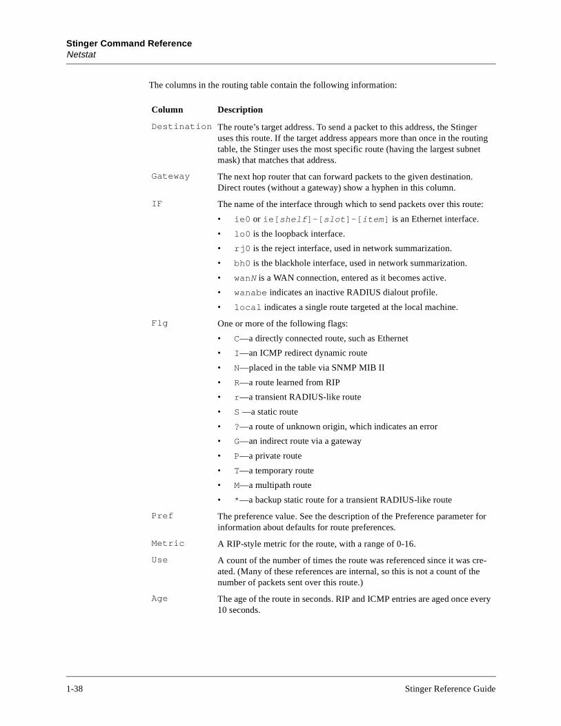
The columns in the routing table contain the following information:
Column Description
Destination The route’s target address. To send a packet to this address, the Stingeuses this route. If the target address appears more than once in the routable, the Stinger uses the most specific route (having the largest subnemask) that matches that address.
Gateway The next hop router that can forward packets to the given destination. Direct routes (without a gateway) show a hyphen in this column.
IF The name of the interface through which to send packets over this route
• ie0 or ie[shelf]-[slot]-[item] is an Ethernet interface.
• lo0 is the loopback interface.
• rj0 is the reject interface, used in network summarization.
• bh0 is the blackhole interface, used in network summarization.
• wanN is a WAN connection, entered as it becomes active.
• wanabe indicates an inactive RADIUS dialout profile.
• local indicates a single route targeted at the local machine.
Flg One or more of the following flags:
• C—a directly connected route, such as Ethernet
• I—an ICMP redirect dynamic route
• N—placed in the table via SNMP MIB II
• R—a route learned from RIP
• r—a transient RADIUS-like route
• S —a static route
• ?—a route of unknown origin, which indicates an error
• G—an indirect route via a gateway
• P—a private route
• T—a temporary route
• M—a multipath route
• *—a backup static route for a transient RADIUS-like route
Pref The preference value. See the description of the Preference parameterinformation about defaults for route preferences.
Metric A RIP-style metric for the route, with a range of 0-16.
Use A count of the number of times the route was referenced since it was crated. (Many of these references are internal, so this is not a count of thnumber of packets sent over this route.)
Age The age of the route in seconds. RIP and ICMP entries are aged once e10 seconds.
1-38 Stinger Reference Guide
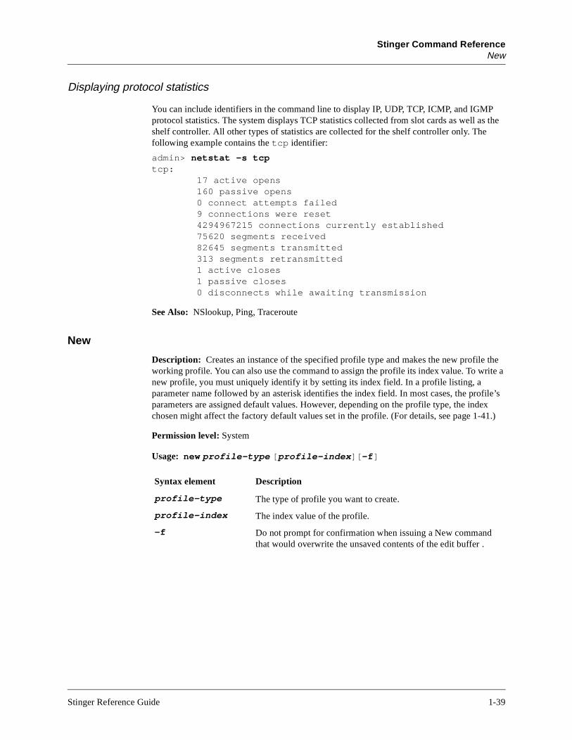
Stinger Command ReferenceNew
file’s ex 41.)
Displaying protocol statistics
You can include identifiers in the command line to display IP, UDP, TCP, ICMP, and IGMP protocol statistics. The system displays TCP statistics collected from slot cards as well as the shelf controller. All other types of statistics are collected for the shelf controller only. The following example contains the tcp identifier:
admin> netstat -s tcp tcp: 17 active opens 160 passive opens 0 connect attempts failed 9 connections were reset 4294967215 connections currently established 75620 segments received 82645 segments transmitted 313 segments retransmitted 1 active closes 1 passive closes 0 disconnects while awaiting transmission
See Also: NSlookup, Ping, Traceroute
New
Description: Creates an instance of the specified profile type and makes the new profile the working profile. You can also use the command to assign the profile its index value. To write a new profile, you must uniquely identify it by setting its index field. In a profile listing, a parameter name followed by an asterisk identifies the index field. In most cases, the proparameters are assigned default values. However, depending on the profile type, the indchosen might affect the factory default values set in the profile. (For details, see page 1-
Permission level: System
Usage: new profile-type [profile-index][-f]
Syntax element Description
profile-type The type of profile you want to create.
profile-index The index value of the profile.
-f Do not prompt for confirmation when issuing a New command that would overwrite the unsaved contents of the edit buffer .
Stinger Reference Guide 1-39
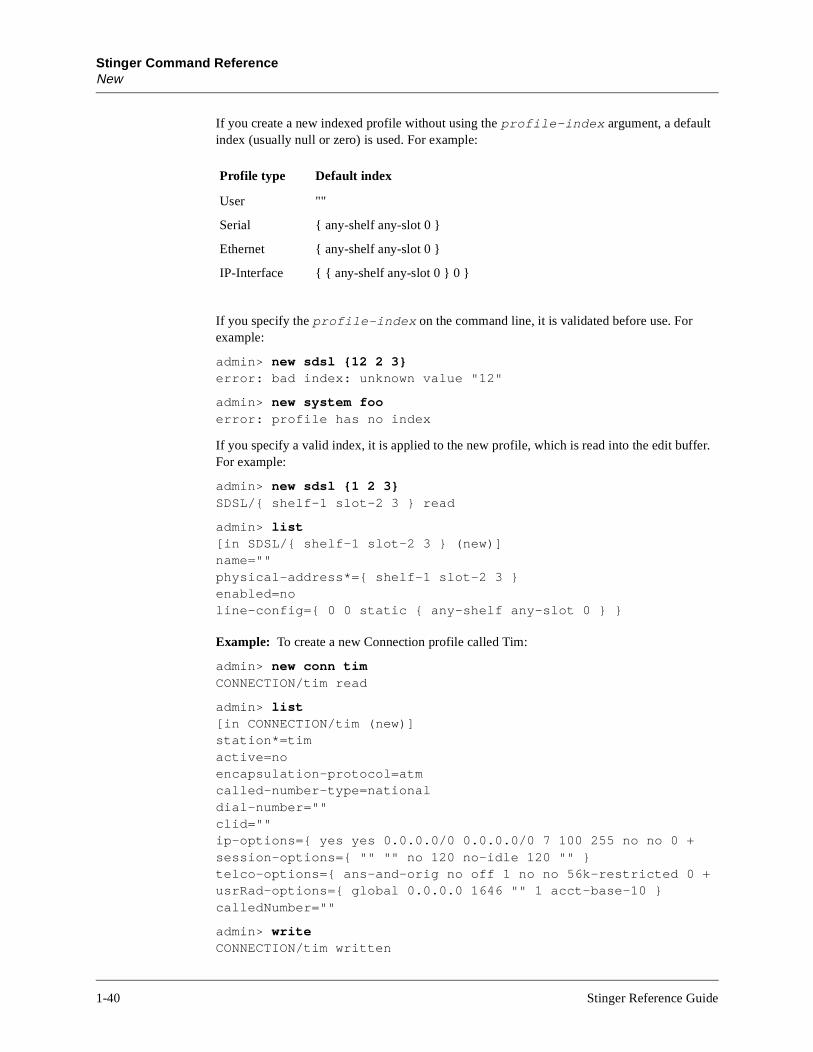
Stinger Command ReferenceNew
If you create a new indexed profile without using the profile-index argument, a default index (usually null or zero) is used. For example:
If you specify the profile-index on the command line, it is validated before use. For example:
admin> new sdsl {12 2 3}error: bad index: unknown value "12"
admin> new system fooerror: profile has no index
If you specify a valid index, it is applied to the new profile, which is read into the edit buffer. For example:
admin> new sdsl {1 2 3} SDSL/{ shelf-1 slot-2 3 } read
admin> list[in SDSL/{ shelf-1 slot-2 3 } (new)]name=""physical-address*={ shelf-1 slot-2 3 }enabled=noline-config={ 0 0 static { any-shelf any-slot 0 } }
Example: To create a new Connection profile called Tim:
admin> new conn timCONNECTION/tim read
admin> list[in CONNECTION/tim (new)]station*=timactive=noencapsulation-protocol=atmcalled-number-type=nationaldial-number=""clid=""ip-options={ yes yes 0.0.0.0/0 0.0.0.0/0 7 100 255 no no 0 +session-options={ "" "" no 120 no-idle 120 "" }telco-options={ ans-and-orig no off 1 no no 56k-restricted 0 +usrRad-options={ global 0.0.0.0 1646 "" 1 acct-base-10 }calledNumber=""
admin> writeCONNECTION/tim written
Profile type Default index
User ""
Serial { any-shelf any-slot 0 }
Ethernet { any-shelf any-slot 0 }
IP-Interface { { any-shelf any-slot 0 } 0 }
1-40 Stinger Reference Guide
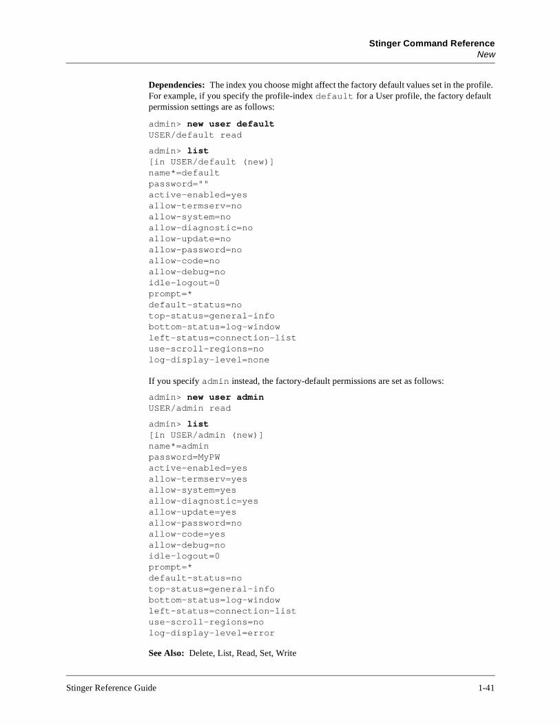
Stinger Command ReferenceNew
Dependencies: The index you choose might affect the factory default values set in the profile. For example, if you specify the profile-index default for a User profile, the factory default permission settings are as follows:
admin> new user defaultUSER/default read
admin> list[in USER/default (new)]name*=defaultpassword=""active-enabled=yesallow-termserv=noallow-system=noallow-diagnostic=noallow-update=noallow-password=noallow-code=noallow-debug=noidle-logout=0prompt=*default-status=notop-status=general-infobottom-status=log-windowleft-status=connection-listuse-scroll-regions=nolog-display-level=none
If you specify admin instead, the factory-default permissions are set as follows:
admin> new user adminUSER/admin read
admin> list[in USER/admin (new)]name*=adminpassword=MyPWactive-enabled=yesallow-termserv=yesallow-system=yesallow-diagnostic=yesallow-update=yesallow-password=noallow-code=yesallow-debug=noidle-logout=0prompt=*default-status=notop-status=general-infobottom-status=log-windowleft-status=connection-listuse-scroll-regions=nolog-display-level=error
See Also: Delete, List, Read, Set, Write
Stinger Reference Guide 1-41

Stinger Command ReferenceNSlookup
cess
the
NSlookup
Description: Resolves the IP address of a specified hostname by performing a DNS lookup. The IP-Global profile must be configured with the address of at least one DNS server. For information about configuring DNS, see the Stinger Configuration Guide.
Permission level: Diagnostic
Usage: nslookup hostname
Example: To look up a host’s IP address in DNS:
admin> nslookup host-231Resolving host host-231.IP address for host host-231 is 10.65.12.231.
See Also: ARPtable, Netstat
NVRAM
Description: Provides functions for managing or clearing onboard nonvolatile random acmemory (NVRAM). The onboard NVRAM stores the system configuration. Clearing NVRAM initializes the system. It comes up unconfigured, just as it was when you first installed it. You can then restore the configuration from a recent backup. For details, seeStinger Administration Guide.
Permission level: Update
Usage: nvram -f|-t|-u|-c|-?
Example: To display memory usage information, specify the -u option:
admin> nvram -uNVRAM seg[0]:start 14000098 size 258040 avail 191680 cmpct 0
You can enter the command without any arguments to clear NVRAM and reset the unit:
admin> nvramClear configuration and reboot? [y/n]
Syntax element Description
hostname The hostname for which you want to obtain an IP address.
Option Description
-f Clear NVRAM without prompting for confirmation.
-t Toggle module debug level.
-u Display NVRAM usage statistics.
-c Compact the NVRAM storage.
-? Display a usage summary.
1-42 Stinger Reference Guide
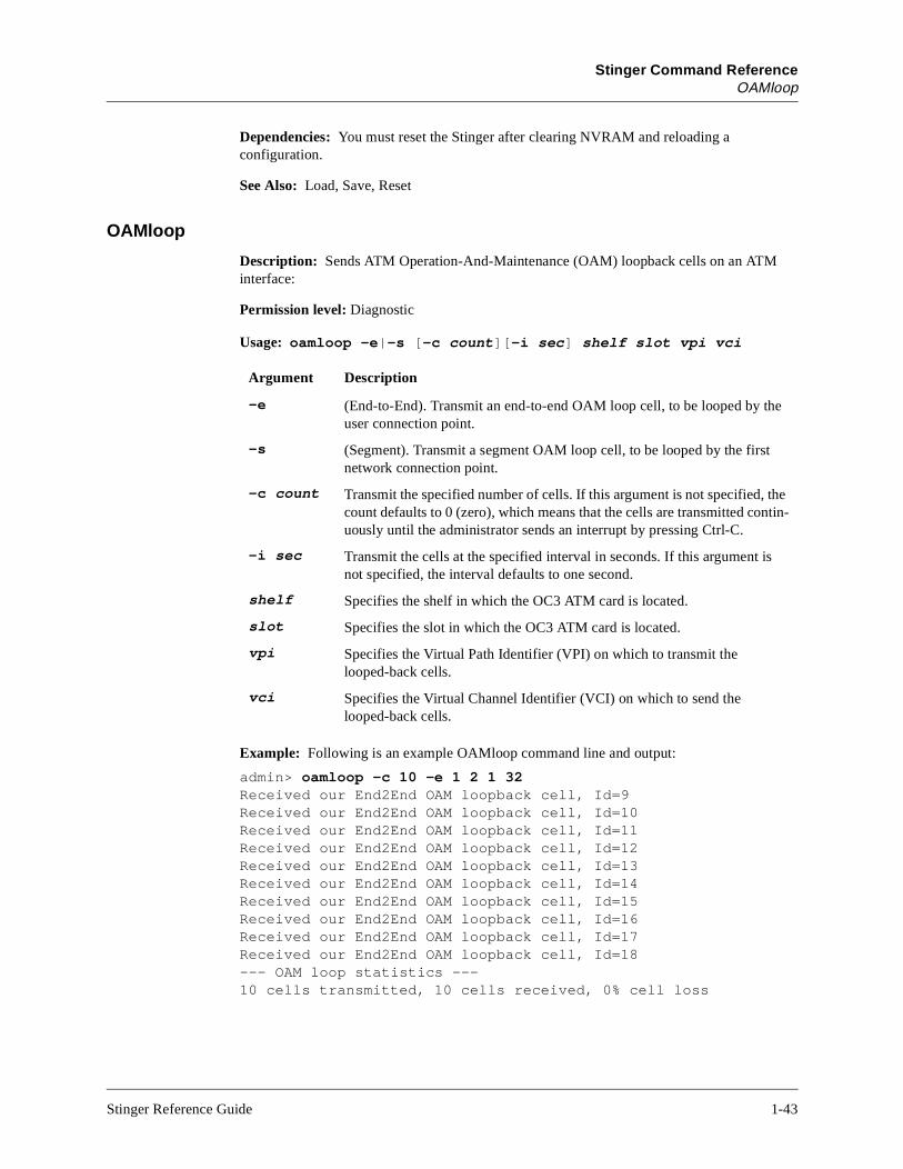
Stinger Command ReferenceOAMloop
Dependencies: You must reset the Stinger after clearing NVRAM and reloading a configuration.
See Also: Load, Save, Reset
OAMloop
Description: Sends ATM Operation-And-Maintenance (OAM) loopback cells on an ATM interface:
Permission level: Diagnostic
Usage: oamloop -e|-s [-c count][-i sec] shelf slot vpi vci
Example: Following is an example OAMloop command line and output:
admin> oamloop -c 10 -e 1 2 1 32Received our End2End OAM loopback cell, Id=9Received our End2End OAM loopback cell, Id=10Received our End2End OAM loopback cell, Id=11Received our End2End OAM loopback cell, Id=12Received our End2End OAM loopback cell, Id=13Received our End2End OAM loopback cell, Id=14Received our End2End OAM loopback cell, Id=15Received our End2End OAM loopback cell, Id=16Received our End2End OAM loopback cell, Id=17Received our End2End OAM loopback cell, Id=18--- OAM loop statistics ---10 cells transmitted, 10 cells received, 0% cell loss
Argument Description
–e (End-to-End). Transmit an end-to-end OAM loop cell, to be looped by the user connection point.
–s (Segment). Transmit a segment OAM loop cell, to be looped by the first network connection point.
–c count Transmit the specified number of cells. If this argument is not specified, the count defaults to 0 (zero), which means that the cells are transmitted contin-uously until the administrator sends an interrupt by pressing Ctrl-C.
–i sec Transmit the cells at the specified interval in seconds. If this argument is not specified, the interval defaults to one second.
shelf Specifies the shelf in which the OC3 ATM card is located.
slot Specifies the slot in which the OC3 ATM card is located.
vpi Specifies the Virtual Path Identifier (VPI) on which to transmit the looped-back cells.
vci Specifies the Virtual Channel Identifier (VCI) on which to send the looped-back cells.
Stinger Reference Guide 1-43

Stinger Command ReferenceOpen
Open
Description: Each slot card has its own processor, memory, operating system, and set of debug commands. The Open command sets up a Telnet-like session across the control bus to one of the slot cards. Then you can execute commands on that slot card.
Permission level: Diagnostic
Usage: open 1..9 [1..16]
Example: To open a session with a DS3 card installed in shelf 1, slot 1:
admin> open 1 1
The prompt changes to show your location, and you can list the available commands:
ds3-1/2> ?
? ( user )auth ( user )cbcardif ( debug )checkd ( debug )clear ( user )clock-source ( diagnostic )debug ( diagnostic )debugd ( debug )display ( debug )dp-ram-display ( debug )dpram-test ( debug )dspBypassClients ( debug )dspDial ( debug )dspSetDddTimeslot ( debug )fill ( debug )frreset ( debug )gdb ( debug )help ( user )lifDebug ( debug )logdebug ( debug )logtest ( debug )mibcbagt ( debug )mibcbreq ( debug )mibmgr ( debug )modify ( debug )nailedState ( debug )nlcb ( debug )open ( diagnostic )quit ( user )revision ( debug )slots ( debug )
Syntax element Description
1..9 The shelf number.
1..16 The number of the expansion slot you want to diagnose.
1-44 Stinger Reference Guide

Stinger Command ReferencePing
stackLimit ( debug )stackUsage ( debug )tdm ( debug )timedMsgTest ( debug )tprofmgr ( debug )tss ( debug )update ( debug )version ( system )whoami ( user )
To return to the shelf controller:
ds3-1/2> quit
See Also: Show, Slot
Ping
Description: Sends ICMP echo_request packets to the specified host as a way to verify that the host is up and the transmission path to the host is open. The host returns ICMP echo_response packets, and the command generates statistics about the exchange.
Permission level: Diagnostic
Usage: ping [-q|-v][-c count][-i delay][-s packetsize] hostname
Example: Pinging a host named Host-231 on a local network:
admin> ping host-231PING host-231 (10.65.12.231): 56 data bytes64 bytes from 10.65.12.231: icmp_seq=0 ttl=255 time=0 ms64 bytes from 10.65.12.231: icmp_seq=1 ttl=255 time=0 ms64 bytes from 10.65.12.231: icmp_seq=2 ttl=255 time=0 ms64 bytes from 10.65.12.231: icmp_seq=3 ttl=255 time=0 ms64 bytes from 10.65.12.231: icmp_seq=4 ttl=255 time=0 ms^C--- host-231 ping statistics ---5 packets transmitted, 5 packets received, 0% packet lossround-trip min/avg/max=0/0/0 ms
Syntax element Description
-q Quiet. Do not display informational messages. Just display the summary lines at the beginning and end of the command.
-v Verbose. List every ICMP packet received, except echo_response packets.
-c count Send only the specified number of packets.
-i delay Wait the specified number of seconds before sending the next packet. The default delay period is one second.
-s packetsize
Send the specified number of data bytes. The default size is 64 bytes, not including the 8-byte ICMP header. The minimum is 16.
hostname The station’s IP address or DNS hostname.
Stinger Reference Guide 1-45
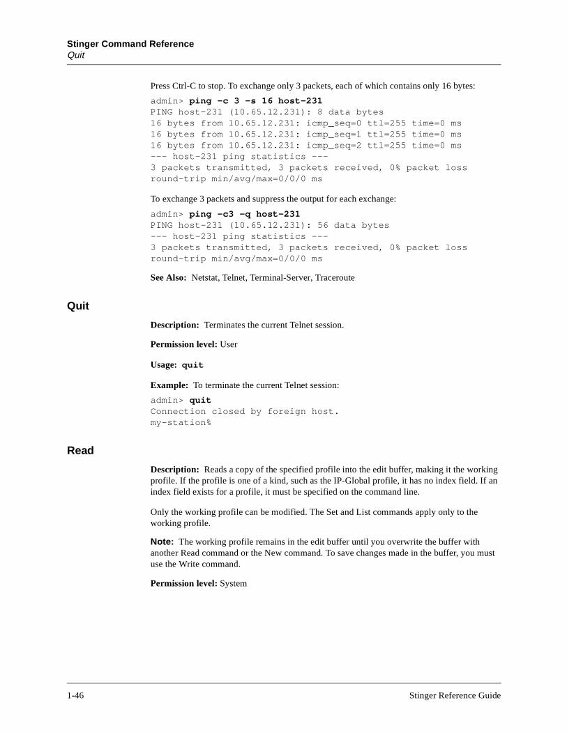
Stinger Command ReferenceQuit
Press Ctrl-C to stop. To exchange only 3 packets, each of which contains only 16 bytes:
admin> ping -c 3 -s 16 host-231PING host-231 (10.65.12.231): 8 data bytes16 bytes from 10.65.12.231: icmp_seq=0 ttl=255 time=0 ms16 bytes from 10.65.12.231: icmp_seq=1 ttl=255 time=0 ms16 bytes from 10.65.12.231: icmp_seq=2 ttl=255 time=0 ms--- host-231 ping statistics ---3 packets transmitted, 3 packets received, 0% packet lossround-trip min/avg/max=0/0/0 ms
To exchange 3 packets and suppress the output for each exchange:
admin> ping -c3 -q host-231PING host-231 (10.65.12.231): 56 data bytes--- host-231 ping statistics ---3 packets transmitted, 3 packets received, 0% packet lossround-trip min/avg/max=0/0/0 ms
See Also: Netstat, Telnet, Terminal-Server, Traceroute
Quit
Description: Terminates the current Telnet session.
Permission level: User
Usage: quit
Example: To terminate the current Telnet session:
admin> quitConnection closed by foreign host.my-station%
Read
Description: Reads a copy of the specified profile into the edit buffer, making it the working profile. If the profile is one of a kind, such as the IP-Global profile, it has no index field. If an index field exists for a profile, it must be specified on the command line.
Only the working profile can be modified. The Set and List commands apply only to the working profile.
Note: The working profile remains in the edit buffer until you overwrite the buffer with another Read command or the New command. To save changes made in the buffer, you must use the Write command.
Permission level: System
1-46 Stinger Reference Guide
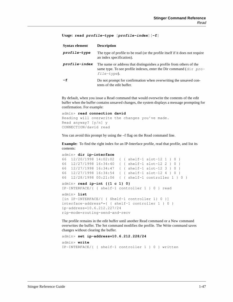
Stinger Command ReferenceRead
e
Usage: read profile-type [profile-index][-f]
By default, when you issue a Read command that would overwrite the contents of the edit buffer when the buffer contains unsaved changes, the system displays a message prompting for confirmation. For example:
admin> read connection davidReading will overwrite the changes you’ve made.Read anyway? [y/n] yCONNECTION/david read
You can avoid this prompt by using the –f flag on the Read command line.
Example: To find the right index for an IP-Interface profile, read that profile, and list its contents:
admin> dir ip-interface66 12/20/1998 14:02:02 { { shelf-1 slot-12 1 } 0 }66 12/27/1998 16:34:40 { { shelf-1 slot-12 2 } 0 }66 12/27/1998 16:34:47 { { shelf-1 slot-12 3 } 0 }66 12/27/1998 16:34:54 { { shelf-1 slot-12 4 } 0 }66 12/28/1998 00:21:06 { { shelf-1 controller 1 } 0 }
admin> read ip-int {{1 c 1} 0}IP-INTERFACE/{ { shelf-1 controller 1 } 0 } read
admin> list[in IP-INTERFACE/{ { Shelf-1 controller 1} 0 }]interface-address*={ { shelf-1 controller 1 } 0 }ip-address=10.6.212.227/24rip-mode=routing-send-and-recv
The profile remains in the edit buffer until another Read command or a New command overwrites the buffer. The Set command modifies the profile. The Write command saveschanges without clearing the buffer.
admin> set ip-address=10.6.212.228/24
admin> writeIP-INTERFACE/{ { shelf-1 controller 1 } 0 } written
Syntax element Description
profile-type The type of profile to be read (or the profile itself if it does not requiran index specification).
profile-index The name or address that distinguishes a profile from others of the same type. To see profile indexes, enter the Dir command (dir pro-file-type).
-f Do not prompt for confirmation when overwriting the unsaved con-tents of the edit buffer.
Stinger Reference Guide 1-47

Stinger Command ReferenceRefresh
The working profile is represented by a period character. Even after you have used the Get command to display other profiles, or have executed other commands, you can still use the Get command to display the working profile:
admin> get .[in IP-INTERFACE/{ { Shelf-1 controller 1} 0 }]interface-address*={ { shelf-1 controller 1 } 0 }ip-address=10.6.212.228/24rip-mode=routing-send-and-recv
See Also: Get, List, New, Set, Write
Refresh
Description: Opens a connection to a RADIUS server and retrieves the latest configuration information.
Permission level: System
Usage: refresh -a|-n|-p|-r|-t
Reset
Description: Resets the Stinger. When you reset the unit, it restarts, and all active connections are terminated. All users are logged out and the default security level is reactivated. In addition, a system reset can cause a WAN line to temporarily be shut down due to momentary loss of signaling or framing information. After a reset, the Stinger runs POST (power-on self tests).
Permission level: Update
Usage: reset [-f]
Example: To reset the unit:
admin> reset
Option Description
-a Refresh all types of configuration.
-n Refresh nailed profiles configuration.
-r Refresh static routes configuration.
-t Refresh terminal server configuration.
-s Clears the current Source Auth information (purging all existing Source Auth entries from the cache) and reloads it from RADIUS.
Option Description
-f Force a reset without prompting for confirmation.
1-48 Stinger Reference Guide
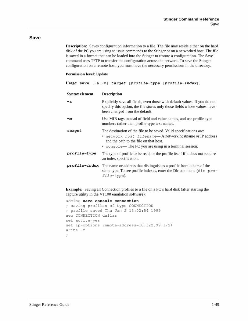
Stinger Command ReferenceSave
t e
Save
Description: Saves configuration information to a file. The file may reside either on the hard disk of the PC you are using to issue commands to the Stinger or on a networked host. The file is saved in a format that can be loaded into the Stinger to restore a configuration. The Save command uses TFTP to transfer the configuration across the network. To save the Stinger configuration on a remote host, you must have the necessary permissions in the directory.
Permission level: Update
Usage: save [-a|-m] target [profile-type [profile-index]]
Example: Saving all Connection profiles to a file on a PC’s hard disk (after starting the capture utility in the VT100 emulation software):
admin> save console connection; saving profiles of type CONNECTION; profile saved Thu Jan 2 13:02:54 1999new CONNECTION dallasset active=yesset ip-options remote-address=10.122.99.1/24write -f;
Syntax element Description
-a Explicitly save all fields, even those with default values. If you do nospecify this option, the file stores only those fields whose values havbeen changed from the default.
-m Use MIB tags instead of field and value names, and use profile-typenumbers rather than profile-type text names.
target The destination of the file to be saved. Valid specifications are:• network host filename— A network hostname or IP address
and the path to the file on that host.• console— The PC you are using in a terminal session.
profile-type The type of profile to be read, or the profile itself if it does not requirean index specification.
profile-index The name or address that distinguishes a profile from others of the same type. To see profile indexes, enter the Dir command (dir pro-file-type).
Stinger Reference Guide 1-49
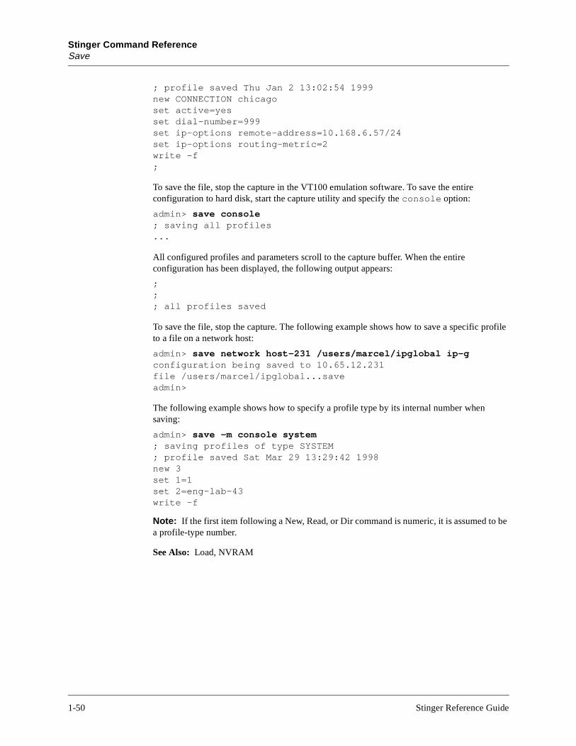
Stinger Command ReferenceSave
; profile saved Thu Jan 2 13:02:54 1999new CONNECTION chicagoset active=yesset dial-number=999set ip-options remote-address=10.168.6.57/24set ip-options routing-metric=2write -f;
To save the file, stop the capture in the VT100 emulation software. To save the entire configuration to hard disk, start the capture utility and specify the console option:
admin> save console; saving all profiles...
All configured profiles and parameters scroll to the capture buffer. When the entire configuration has been displayed, the following output appears:
;;; all profiles saved
To save the file, stop the capture. The following example shows how to save a specific profile to a file on a network host:
admin> save network host-231 /users/marcel/ipglobal ip-gconfiguration being saved to 10.65.12.231file /users/marcel/ipglobal...saveadmin>
The following example shows how to specify a profile type by its internal number when saving:
admin> save -m console system; saving profiles of type SYSTEM; profile saved Sat Mar 29 13:29:42 1998new 3set 1=1set 2=eng-lab-43write -f
Note: If the first item following a New, Read, or Dir command is numeric, it is assumed to be a profile-type number.
See Also: Load, NVRAM
1-50 Stinger Reference Guide

Stinger Command ReferenceScreen
Screen
Description: Changes window display sizes for the current session only.
Permission level: Update
Usage: screen screen-length [status-length]
If the Status window is open when you execute the Screen command, the window is resized dynamically. If it is not open, the Status window is resized when you next open it.
Example: admin> screen 55 22
If only the screen-length argument is specified, and the stored status-length is not less than the specified value by 6 lines, the status-length is automatically adjusted. This scenario is demonstrated in the following example:
admin> screen 55 22new screen-length 55new status-length 22
admin> screen 24error: screen-length conflict, adjusting status-length from 22 to 18new screen-length 24new status-length 18
SDSLlines
Description: Displays SDSL channel information.
Permission level: System
Usage: sdsllines -a|-d|-f|-u
Syntax element Description
screen-length The number of lines displayed in the command-line window. The default is 24 lines, which is the minimum size. The maximum size is 999 lines
status-length The number of lines displayed in the Status window, including dividing lines. The default is 18 lines, which is the minimum size. The maxi-mum size is 993 lines. The status-length value must be less than the screen-length by at least six lines
Option Description
-a Display all available channels.
-d Display all disabled channels.
-f Display all possible channels.
-u Display all in-use channels.
Stinger Reference Guide 1-51
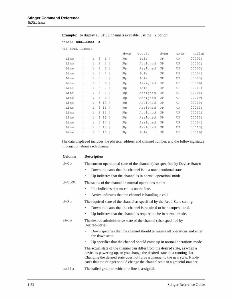
Stinger Command ReferenceSDSLlines
ter
de.
i-r.
Example: To display all SDSL channels available, use the -a option:
admin> sdsllines -a
All SDSL lines:
(dvOp dvUpSt dvRq sAdm nailg)
Line { 1 3 1 } (Up Idle UP UP 00001)
Line { 1 3 2 } (Up Assigned UP UP 00002)
Line { 1 3 3 } (Up Assigned UP UP 00003)
Line { 1 3 4 } (Up Idle UP UP 00004)
Line { 1 3 5 } (Up Idle UP UP 00005)
Line { 1 3 6 } (Up Assigned UP UP 00006)
Line { 1 3 7 } (Up Idle UP UP 00007)
Line { 1 3 8 } (Up Assigned UP UP 00008)
Line { 1 3 9 } (Up Assigned UP UP 00009)
Line { 1 3 10 } (Up Assigned UP UP 00010)
Line { 1 3 11 } (Up Assigned UP UP 00011)
Line { 1 3 12 } (Up Assigned UP UP 00012)
Line { 1 3 13 } (Up Assigned UP UP 00013)
Line { 1 3 14 } (Up Assigned UP UP 00014)
Line { 1 3 15 } (Up Assigned UP UP 00015)
Line { 1 3 16 } (Up Idle UP UP 00016)
The data displayed includes the physical address and channel number, and the following status information about each channel:
Column Description
dvOp The current operational state of the channel (also specified by Device-State):
• Down indicates that the channel is in a nonoperational state.
• Up indicates that the channel is in normal operations mode.
dvUpSt The status of the channel in normal operations mode:
• Idle indicates that no call is on the line.
• Active indicates that the channel is handling a call.
dvRq The required state of the channel as specified by the Reqd-State setting:
• Down indicates that the channel is required to be nonoperational.
• Up indicates that the channel is required to be in normal mode.
sAdm The desired administrative state of the channel (also specified by Desired-State):
• Down specifies that the channel should terminate all operations and enthe down state.
• Up specifies that the channel should come up in normal operations mo
The actual state of the channel can differ from the desired state, as when adevice is powering up, or you change the desired state on a running slot. Changing the desired state does not force a channel to the new state. It indcates that the Stinger should change the channel state in a graceful manne
nailg The nailed group to which the line is assigned.
1-52 Stinger Reference Guide

Stinger Command ReferenceSet
t or le.
rk-
y
n
Set
Description: Sets a parameter’s value or displays help text for a parameter in the currenspecified context of the working profile. To save the new setting, you must write the profi
Permission level: System
Usage: set param-name [param-index] [subprofile]=value|?
See Also: List, New, Read, Write
Show
Description: Displays information about installed slot cards and their status.
Permission level: System
Usage: show shelf-number [slot-number [item-number]]
Example: To display all installed modules:
admin> show 1Shelf 1 ( standalone ): { shelf-1 slot-4 0 } UP al-dmtadsl-atm-card { shelf-1 slot-6 0 } UP sdsl-atm-card
Syntax element Description
param-name Name of the parameter in the current or specified context of the woing profile.
param-index Parameter index, which might be required for some complex or arraparameters. (See the Physical-Address example below.)
subprofile Subprofile name within the working profile. By specifying its name othe command line, you can set a parameter in a subprofile without opening the subprofile.
value Legal parameter value.
? Display help text about the specified parameter.
Syntax element Description
shelf-number The number of a Stinger shelf.
slot-number The number of an expansion slot in the specified shelf (1–16).
item-number The number of a specific item (device or channel) on the slot card.
Stinger Reference Guide 1-53

Stinger Command ReferenceSlot
The output includes the address of each slot in which an expansion slot card is installed, the status of the card, and the type of card installed. The status can be one of the following:
See Also: Device, Slot
Slot
Description: Changes the administrative state of a slot card, forcing a state change (up or down). The down state allows temporary removal of a card without the loss of its configuration.
Permission level: Diagnostic
Usage: slot -u|-d|-r|-t|-b|? [shelf-number] slot-number]
Status Description
UP Normal operational mode. The card is up and running.
DOWN Not in an operational mode. The card has shut down all functions and can be downed by the shelf controller.
POST The download is complete, and the devices in the card are running power-on self tests.
BOOT The card is running BOOT code. Under normal conditions, the LOAD status follows.
LOAD The card is loading code as part of coming up.
RESET The card is being reset.
NONE The card has been swapped out, but its configuration remains in flash space.
OCCUPIED The card is using two slots.
Syntax element Description
-u Bring up the specified slot card.
-d Bring down the specified slot card.
-r Delete the profiles for a card that has been removed.
-t Toggle module debug level.
-b Force hardware reset.
-w Change or display watchdog failure limit.
-? Display a usage summary.
shelf-number The number of a Stinger shelf.
slot-number The number of an expansion slot in the specified shelf (1–16).
1-54 Stinger Reference Guide

Stinger Command ReferenceStatus
Example: To bring up the expansion module in slot 5:
admin> slot -u 5slot 1/5 state change forced
In the next example, a card has been removed, as indicated by a status of NONE in the output of the Show command:
admin> show 1 4
Shelf 1 ( standalone ): { shelf-1 slot-4 0 } UP al-dmtadsl-atm-card:
{ shelf-1 slot-4 1 } UP xdsl-12-line1
{ shelf-1 slot-4 2 } UP xdsl-12-line-2
{ shelf-1 slot-4 3 } UP xdsl-12-line-3 { shelf-1 slot-4 4 } UP xdsl-12-line-4
{ shelf-1 slot-4 5 } UP xdsl-12-line-5
{ shelf-1 slot-4 6 } UP xdsl-12-line-6 { shelf-1 slot-4 7 } UP xdsl-12-line-7
{ shelf-1 slot-4 8 } UP xdsl-12-line-8
{ shelf-1 slot-4 9 } UP xdsl-12-line-9 { shelf-1 slot-4 10 } UP xdsl-12-line-10
{ shelf-1 slot-4 11 } UP xdsl-12-line-11
{ shelf-1 slot-4 12 } NONE xdsl-12-line-12 { shelf-1 slot-4 13 } xdsl-12-virt-device
The NONE status indicates that the card was removed but that its profiles have been saved. The Stinger remembers that a card was in that slot and saves its profiles until a card of a different type is installed in the same slot, or until you delete the profile:
admin> slot -r 4
slot 1/4 removed
Either action deletes all the old profiles associated with the slot. When you insert a different type of card, the system creates appropriate new profiles.
See Also: Device, Open, Show
Status
Description: Displays the status windows. You can configure the content of the windows to show connection, line, or log-message information. For detailed information, see the Stinger Administration Guide.
Permission level: System
Usage: status [on|off]
Syntax element Description
on Display the status windows.
off Hide the status windows.
Stinger Reference Guide 1-55

Stinger Command ReferenceTelnet
Example: To display status windows:
admin> status
or
admin> status on
To hide the windows:
admin> status
or
admin> status off
See Also: Connection, Line, Log, View
Telnet
Description: Opens a Telnet session across the network to the specified host.
Permission level: Diagnostic
Usage: telnet [-a|-b|-t][-l[e]|-r[e]] hostname [portnumber]
2 Connections StatusSerial number: 6201732 Version: 1.0F
Rx Pkt: 11185897 Tx Pkt: 42460 Col: 129
12/26/1998 12:20:15 Up: 3 days, 21:47:32
M: 29 L: info Src: shelf-1/controller
Issued: 16:48:02, 09/27/1998
[Next/Last Conn: <dn/up arw>, Next?Last Page: <pg dn/up>, Exit: <esc>]
001 tomw TCP 1/7/14 19200002 timl TCP 1/7/3 56000
Syntax element Description
-a ASCII mode, or standard 7-bit mode. In 7-bit mode, bit 8 is set to 0 (zero). This value is the default if no other mode is specified.
-b Binary mode. The Stinger attempts to negotiate the Telnet 8-bit binary option with the server at the remote end. You can run X-Modem and other 8-bit file transfer protocols in this mode.
-t Transparent mode. You can send and receive binary files, and run the same file-transfer protocols, without having to be in Binary mode.
-l[e] Local echo. As you type a line, it echoes on your terminal screen, but is not actually transmitted until you enter a carriage return.
-r[e] Remote echo. Turn local echo off.
hostname The IP address or DNS name of a networked host.
portnumber A port number for Telnet sessions. The default port is 23.
1-56 Stinger Reference Guide

Stinger Command ReferenceTerminal-Server
Example: To open a Telnet session to Host-231:
admin> telnet host-231Connecting to host-231 (10.65.12.231)...Escape character is ’^]’Connected
You can also open a session after starting the Telnet program. To display the available commands:
admin> telnet
telnet> ?? Displays this information.help " " "open Connect to a site.quit Quit Telnet.close Close current Telnet connection.send Send Telnet command. Type ’send ?’ for help.set Set special char. Type ’set ?’ for help.
Note: During an open Telnet connection, type Ctrl-] to display the telnet> prompt and the Telnet command-line interface. Any valid Telnet command returns you to the open session. Note that Ctrl-] does not function in binary mode Telnet. If you log into the Stinger by Telnet, you might want to change its escape sequence from Ctrl-] to a different setting.
See Also: Ping
Terminal-Server
Description: Starts terminal-server mode, which has its own command interface.
Permission level: Termserv
Usage: terminal-server
Example: To enter terminal-server mode and display the list of available commands:
admin> terminal-server
admin% ?
? Display help information
help " " "
quit Closes terminal server session
hangup " " " "
local Go to local mode
remote remote <station>
set Set various items. Type ’set ?’ for help
show Show various tables. Type ’show ?’ for help
iproute Manage IP routes. Type ’iproute ?’ for help
telnet telnet [-a|-b|-t] <host-name> [<port-number>]
tcp tcp <host-name> <port-number>
ping ping <host-name>
traceroute Trace route to host. Type ’traceroute -?’ for help
rlogin rlogin [-l user -ec] <host-name>
Stinger Reference Guide 1-57
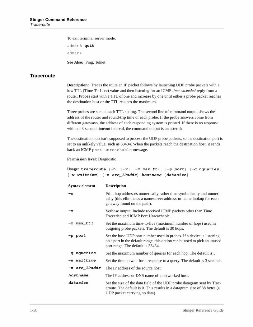
Stinger Command ReferenceTraceroute
port is sends
ri-h
ng sed
nds.
ac- (a
To exit terminal server mode:
admin% quit
admin>
See Also: Ping, Telnet
Traceroute
Description: Traces the route an IP packet follows by launching UDP probe packets with a low TTL (Time-To-Live) value and then listening for an ICMP time exceeded reply from a router. Probes start with a TTL of one and increase by one until either a probe packet reaches the destination host or the TTL reaches the maximum.
Three probes are sent at each TTL setting. The second line of command output shows the address of the router and round-trip time of each probe. If the probe answers come from different gateways, the address of each responding system is printed. If there is no response within a 3-second timeout interval, the command output is an asterisk.
The destination host isn’t supposed to process the UDP probe packets, so the destinationset to an unlikely value, such as 33434. When the packets reach the destination host, it back an ICMP port unreachable message.
Permission level: Diagnostic
Usage: traceroute [-n] [-v] [-m max_ttl] [-p port] [-q nqueries]
[-w waittime] [-s src_IPaddr] hostname [datasize]
Syntax element Description
-n Print hop addresses numerically rather than symbolically and numecally (this eliminates a nameserver address-to-name lookup for eacgateway found on the path).
-v Verbose output. Include received ICMP packets other than Time Exceeded and ICMP Port Unreachable.
-m max_ttl Set the maximum time-to-live (maximum number of hops) used in outgoing probe packets. The default is 30 hops.
-p port Set the base UDP port number used in probes. If a device is listenion a port in the default range, this option can be used to pick an unuport range. The default is 33434.
-q nqueries Set the maximum number of queries for each hop. The default is 3.
-w waittime Set the time to wait for a response to a query. The default is 3 seco
-s src_IPaddr The IP address of the source host.
hostname The IP address or DNS name of a networked host.
datasize Set the size of the data field of the UDP probe datagram sent by Treroute. The default is 0. This results in a datagram size of 38 bytesUDP packet carrying no data).
1-58 Stinger Reference Guide

Stinger Command ReferenceUptime
Example: To trace the route to Host-231:
admin> traceroute host-231
traceroute to host-231 (10.65.12.231), 30 hops max, 0 byte packets
1 host-231.abc.com (10.65.12.231) 0 ms 0 ms 0 ms
To perform the same trace, but with a maximum TTL of 60 hops:
admin> traceroute -m 60 host-231
traceroute to host-231 (10.65.12.231), 60 hops max, 0 byte packets
1 host-231.abc.com (10.65.12.231) 0 ms 0 ms 0 ms
The following annotations can appear after the time field:
See Also: Ping, Netstat
Uptime
Description: Reports how long the system has been up and how long individual cards have been up.
Permission level: System
Usage: uptime [[-a]|[[shelf] slot ]]
Annotation Description
!H Host reached.
!N Network unreachable.
!P Protocol unreachable.
!S Source route failed. This event should not occur, and might indicate that there is a problem with the associated device.
!F Fragmentation needed. This event should not occur, and might indi-cate that there is a problem with the associated device.
!? An ICMP subcode. This event should not occur.
!?? Reply received with inappropriate type. This event should not occur.
Syntax element Description
No arguments Display the system uptime.
-a Display the uptime for all slot cards.
slot Display the uptime for the specified slot card on the master shelf.
shelf slot Display the uptime for the slot card specified by shelf and slot.
Stinger Reference Guide 1-59

Stinger Command ReferenceUserstat
Example: The following example shows the uptime for all slot cards in the Up state. (Cards that are not in the Up state are not reported.)
admin> uptime -a
17:50:44
{ shelf-1 slot-4 } al-dmtadsl-atm-card 0 days 02:45:42 8.0a0e0
{ shelf-1 slot-6 } sdsl-atm-card 0 days 02:45:48 8.0a0e0
{ shelf-1 control-module } shelf-controller 0 days 02:47:05 8.0a0e0
To enable network management stations to obtain uptime information, the following SNMP variable has been added to the Ascend Enterprise MIB:
slotLastChange OBJECT-TYPE
SYNTAX TimeTicks
ACCESS read-only
STATUS mandatory
DESCRIPTION "The value of sysUpTime at the time the slot card
entered its current state."
::= { slotEntry 9 }
The slotLastChange variable reports the value of sysUpTime at the time the slot card entered its current state.
Userstat
Description: Displays user session status.
Permission level: System
Usage: userstat [-s|-l|-d|-k sessionid]
Example: To display user session status:
admin> userstat
SessionID Line/Chan Slot:Item Tx/Rx Rate Svc Address Username
228687860 1.01.02/01 1:03:01/01 56K/56K TCP 10.100.0.1 barney
228687861 1.02.03/02 1:04:02/00 28800/33600 TCP 10.168.6.24 jake
<end user list> 2 active user(s)
Syntax element Description
-s Show session information in an 80-character-wide format (the default).
-l Show enhanced status information in a 140-character-wide format.
-d Dump the output to the display, rather than show it one page at a time.
-k sessionid Terminate a user session that uses SLIP, Telnet, Telnet binary, Raw TCP, or the terminal server. The -k option does not terminate DTPT service types.
1-60 Stinger Reference Guide

Stinger Command ReferenceUserstat
The output contains the following fields:
To terminate a user session, include the -k option and session ID with the Userstat command. For example:
admin> userstat
SessionID Line/Chan Slot:Item Rate Svc Address Username
246986325 1.01.02/01 1:13:01/000 33600 TCP 100.100.8.2 100.100.8.2
<end user list> 1 active user(s)
admin> userstat -k 246986325
Session 246986325 cleared
Field Description
SessionID Unique ID assigned to the session.
Line/Chan Physical address (shelf.slot.line/channel) of the network port on which the connection was established.
Slot:Item Shelf:slot:item/logical-item of the host port to which the call was routed.
Tx/Rx Rate Transmit and receive rates.
Svc Type of service in use for the session. Following are the possible values:
--- (The service is being negotiated.)SLP (Serial Line IP)TLN (Telnet)BTN (Binary Telnet)TCP (raw TCP)TRM (Terminal Server)VCN (Virtual Connect)DTP (DTPT)
Dialed#(displays only with -l option)
The number dialed to initiate this session.
ConnTime(displays only with -l option)
The amount of time (in hours:minutes:seconds format) since the session was established.
IdleTime(displays only with -l option)
The amount of time (in hours:minutes:seconds format) since data was last transmitted across the connection.
Stinger Reference Guide 1-61

Stinger Command ReferenceVersion
Version
Description: Displays the current system software version.
Permission level: System
Usage: version
Example: To display the current system software version:
admin> version
Software version 1.2
View
Description: Changes the information displayed in the top or bottom status window.
Permission level: System
Usage: view position status-type
Example: To display session information:
admin> view left session
Syntax element Description
position The window position may be top, bottom, or left, indicating which area of the status window will be affected by the command.
status-type If the specified window position is top or bottom, the window can display one of the following types of status information:• general (general status information)• log (the 32-message log buffer)• line (line and channel status)
If the specified window position is left, the window can display one of the following types of status information:• connection (WAN connection status)• session (management status)
4 Sessions 1/13/8 RA ........ ........ ........
M: 48 L: info Src: shelf-1/controller
Issued: 16:48:02, 09/27/1998
[Next/Last Conn:<dn/up arw>, Next?Last Page: <pg dn/up>, Exit: <esc>]
0 - serial - admin 1 - telnet - tommy 2 - telnet - super 3 - telnet - pubs
1-62 Stinger Reference Guide

Stinger Command ReferenceWhich
See Also: Connection, Line, Log, Status
Which
Description: Enables you to look up the nailed group associated with the port used for an Asynchronous Transfer Mode (ATM) connection.
Permission level: System
Usage: which [-p group |-n port]
Example: admin> which -n {1 4 5}
Nailed group corresponding to port { shelf-1 slot-4 5 } is 155
admin> which -n {1 17 2}
Nailed group corresponding to port { shelf-1 trunk-module-1 1 } is 802
You can use the which command to determine which port is in use when you have the nailed-group assignment of a Connection profile. For example, if the circuit uses nailed-group 296:
admin> which -p 296
The port corresponding to nailed group 296 is: { shelf-1 slot-6 46 }
If the argument specifies a slot that is not populated, or a nailed-group that is not assigned, the command returns a message that the number was not found. For example:
admin> which -p 43
The port corresponding to nailed group 43 is:
NONE!
If more than one port has the same nailed group associated with it (which is illegal), the which command returns all the ports that have this nailed group. Using the which command can be a convenient way to find duplicate nailed-groups. For example:
admin> read sdsl {1 6 46}
SDSL/{ shelf-1 slot-6 46 } read
admin> set line-config nailed-group=801
admin> write
SDSL/{ shelf-1 slot-6 46 } written
admin> which -p 801
The port corresponding to nailed group 801 is:
{ shelf-1 slot-6 46 }
{ shelf-1 trunk-module-1 1 }
Syntax element Description
-p group Specifies the port associated with the nailed-group indicated by group.
-n port Specifies the nailed-up group associated with the port indicated by port.
Stinger Reference Guide 1-63

Stinger Command ReferenceWhoami
t the
Duplicate nailed-group assignments can occur only when the administrator changes default nailed-group numbers. To fix the problem, change the nailed-group assignments in one or more profiles, and then verify by using the which command again.
Whoami
Description: Displays the name of the User profile associated with the current session.
Permission level: User
Usage: whoami
Example: To display the name of your User profile:
admin> whoami
tommy
See Also: Auth
Write
Description: Validates the settings of the working profile and then writes it from the edit buffer to NVRAM.
Note: If the working profile has an index field (a parameter followed by an asterisk), that parameter must have a value or the write is not allowed. If you modify a profile and do not use the Write command before reading another profile, the changes are lost.
Permission level: Update
Usage: write [-f]
If you issue a Write command when the current profile has not been modified from the saved version, the write does not occur and the following message is displayed:
admin> writeNothing new to write; nothing written.
You can force the write to occur by using the –f flag on the Write command line. Note thawrite always occurs if the profile has not been written previously.
Syntax element Description
-f Force the write without prompting for confirmation, overwriting an existing profile if one exists with the same index.
1-64 Stinger Reference Guide

Stinger Command ReferenceWrite
Example: To create a new Connection profile, modify it, and write it to NVRAM:
admin> new conn newyorkCONNECTION/newyork read
admin> list[in CONNECTION/newyork (new)]station*=newyorkactive=noencapsulation-protocol=atmcalled-number-type=nationaldial-number=""clid=""ip-options={ yes yes 0.0.0.0/0 0.0.0.0/0 7 100 255 no no 0 +session-options={ "" "" no 120 no-idle 120 "" }telco-options={ ans-and-orig no off 1 no no 56k-restricted 0 +usrRad-options={ global 0.0.0.0 1646 "" 1 acct-base-10 }calledNumber=""
admin> writeCONNECTION/newyork written
See Also: List, New, Read, Sets
Stinger Reference Guide 1-65

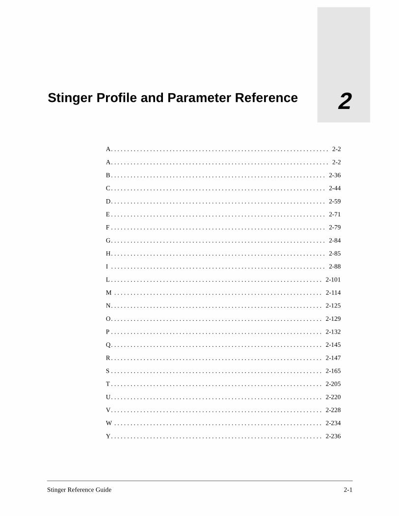
Stinger Reference Guide
2
Stinger Profile and Parameter ReferenceA. . . . . . . . . . . . . . . . . . . . . . . . . . . . . . . . . . . . . . . . . . . . . . . . . . . . . . . . . . . . . . . . . . . 2-2
A. . . . . . . . . . . . . . . . . . . . . . . . . . . . . . . . . . . . . . . . . . . . . . . . . . . . . . . . . . . . . . . . . . . 2-2
B . . . . . . . . . . . . . . . . . . . . . . . . . . . . . . . . . . . . . . . . . . . . . . . . . . . . . . . . . . . . . . . . . . 2-36
C . . . . . . . . . . . . . . . . . . . . . . . . . . . . . . . . . . . . . . . . . . . . . . . . . . . . . . . . . . . . . . . . . . 2-44
D. . . . . . . . . . . . . . . . . . . . . . . . . . . . . . . . . . . . . . . . . . . . . . . . . . . . . . . . . . . . . . . . . . 2-59
E . . . . . . . . . . . . . . . . . . . . . . . . . . . . . . . . . . . . . . . . . . . . . . . . . . . . . . . . . . . . . . . . . . 2-71
F . . . . . . . . . . . . . . . . . . . . . . . . . . . . . . . . . . . . . . . . . . . . . . . . . . . . . . . . . . . . . . . . . . 2-79
G. . . . . . . . . . . . . . . . . . . . . . . . . . . . . . . . . . . . . . . . . . . . . . . . . . . . . . . . . . . . . . . . . . 2-84
H. . . . . . . . . . . . . . . . . . . . . . . . . . . . . . . . . . . . . . . . . . . . . . . . . . . . . . . . . . . . . . . . . . 2-85
I . . . . . . . . . . . . . . . . . . . . . . . . . . . . . . . . . . . . . . . . . . . . . . . . . . . . . . . . . . . . . . . . . . 2-88
L . . . . . . . . . . . . . . . . . . . . . . . . . . . . . . . . . . . . . . . . . . . . . . . . . . . . . . . . . . . . . . . . . 2-101
M . . . . . . . . . . . . . . . . . . . . . . . . . . . . . . . . . . . . . . . . . . . . . . . . . . . . . . . . . . . . . . . . 2-114
N. . . . . . . . . . . . . . . . . . . . . . . . . . . . . . . . . . . . . . . . . . . . . . . . . . . . . . . . . . . . . . . . . 2-125
O. . . . . . . . . . . . . . . . . . . . . . . . . . . . . . . . . . . . . . . . . . . . . . . . . . . . . . . . . . . . . . . . . 2-129
P . . . . . . . . . . . . . . . . . . . . . . . . . . . . . . . . . . . . . . . . . . . . . . . . . . . . . . . . . . . . . . . . . 2-132
Q. . . . . . . . . . . . . . . . . . . . . . . . . . . . . . . . . . . . . . . . . . . . . . . . . . . . . . . . . . . . . . . . . 2-145
R . . . . . . . . . . . . . . . . . . . . . . . . . . . . . . . . . . . . . . . . . . . . . . . . . . . . . . . . . . . . . . . . . 2-147
S . . . . . . . . . . . . . . . . . . . . . . . . . . . . . . . . . . . . . . . . . . . . . . . . . . . . . . . . . . . . . . . . . 2-165
T . . . . . . . . . . . . . . . . . . . . . . . . . . . . . . . . . . . . . . . . . . . . . . . . . . . . . . . . . . . . . . . . . 2-205
U. . . . . . . . . . . . . . . . . . . . . . . . . . . . . . . . . . . . . . . . . . . . . . . . . . . . . . . . . . . . . . . . . 2-220
V. . . . . . . . . . . . . . . . . . . . . . . . . . . . . . . . . . . . . . . . . . . . . . . . . . . . . . . . . . . . . . . . . 2-228
W . . . . . . . . . . . . . . . . . . . . . . . . . . . . . . . . . . . . . . . . . . . . . . . . . . . . . . . . . . . . . . . . 2-234
Y. . . . . . . . . . . . . . . . . . . . . . . . . . . . . . . . . . . . . . . . . . . . . . . . . . . . . . . . . . . . . . . . . 2-236
2-1

Stinger Profile and Parameter ReferenceA
t fail
A
AAL-Type
Description: Specifies the type of ATM Adaptation Layer (AAL) in use for the contract.
Usage: AAL-5 (the default) specifies AAL Type 5, which provides variable bit-rate service. This setting is the only one supported on the unit.
Dependencies: If Encapsulation-Protocol is not set to ATM or ATM-Circuit, AAL-Type does not apply.
Location: ATM-QoS
See Also: Contract-Name, Early-Packet-Discard, Partial-Packet-Discard, QoS-Class
Acct-Checkpoint
Description: Specifies the interval (in seconds) at which to send checkpoint packets to the RADIUS daemon.
Usage: Specify an integer from 0 to 60. The default is 0 (zero).
Example: set acct-checkpoint=30
Location: External-Auth > Rad-Acct-Client
See Also: Acct-ID-Base
Acct-Drop-Stop-On-Auth-Fail
Description: Specifies whether RADIUS Accounting Stop packets are dropped for connections that fail authentication.
Usage: Specify Yes or No. The default is No.
• Yes specifies that RADIUS Accounting Stop packets are dropped for connections thaauthentication.
• No specifies that RADIUS Accounting Stop packets are sent for connections that failauthentication.
Example: set acct-drop-stop-on-auth-fail=yes
Location: External-Auth > Rad-Acct-Client
See Also: Acct-ID-Base, Acct-Key, Acct-Limit-Retry, Acct-Port, Acct-Server-N (N=1–3), Acct-Sess-Interval, Acct-Src-Port, Acct-Stop-Only, Acct-Timeout
2-2 Stinger Reference Guide

Stinger Profile and Parameter ReferenceAcct-Host
e is
the
Acct-Host
Description: Specifies a RADIUS accounting server for the Stinger to use for the connection.
Usage: Enter the IP address of a RADIUS accounting server. The default is 0.0.0.0, which causes the Stinger to look for an accounting server at the address specified by the External-Auth profile.
Example: set acct-host=10.9.8.2/24
Location: Connection station > UsrRad-Options
See Also: Acct-ID-Base, Acct-Key, Acct-Port, Acct-Reset-Time, Acct-Server-N (N=1–3), Acct-Sess-Interval, Acct-Src-Port, Acct-Timeout, Acct-Type, UsrRad-Options
Acct-ID-Base
Description: Specifies whether the numeric base of the RADIUS Acct-Session-ID attribut10 or 16. You can set Acct-ID-Base globally and for each connection.
Usage: Specify one of the following values:
• Acct-Base-10 (the default) specifies a decimal base.
• Acct-Base-16 specifies a hexadecimal base.
The value you specify controls how the Stinger presents the Acct-Session-ID attribute toaccounting server.
Example: set acct-id-base=acct-base-10
Dependencies: Consider the following:
• If Acct-Type does not specify RADIUS, Acct-ID-Base does not apply.
• Changing the value of Acct-ID-Base while accounting sessions are active results in inconsistent reporting between the Start and Stop records.
• The Acct-Session-ID attribute is defined in section 5.5 of the RADIUS accounting specification.
Location: Connection station > UsrRad-Options, External-Auth > Rad-Acct-Client
See Also: Acct-Drop-Stop-On-Auth-Fail, Acct-Key, Acct-Limit-Retry, Acct-Port, Acct-Reset-Time, Acct-Server-N (N=1–3), Acct-Sess-Interval, Acct-Src-Port, Acct-Stop-Only, Acct-Timeout, Acct-Type, Rad-Acct-Client, UsrRad-Options
Stinger Reference Guide 2-3
Stinger Profile and Parameter ReferenceAcct-Key
top a ,
kets to
ry of
er of
N
Acct-Key
Description: Specifies a RADIUS shared secret. A shared secret acts as a password between the Stinger and the accounting server.
Usage: Specify the text of the shared secret. The value you specify must match the value in the RADIUS clients file. If you specify a null value, the system logs the following warning:
warning: acct-key is empty (bad for security)
Example: set acct-key=mypw
Dependencies: If Acct-Type does not specify RADIUS, Acct-Key does not apply.
Location: Connection station > UsrRad-Options, External-Auth > Rad-Acct-Client
See Also: Acct-Drop-Stop-On-Auth-Fail, Acct-ID-Base, Acct-Limit-Retry, Acct-Port, Acct-Reset-Time, Acct-Server-N (N=1–3), Acct-Sess-Interval, Acct-Src-Port, Acct-Stop-Only, Acct-Timeout, Acct-Type, Rad-Acct-Client, UsrRad-Options
Acct-Limit-Retry
Description: Specifies the maximum number of retries for Accounting packets.
When the Stinger is configured for RADIUS accounting, it sends Accounting Start and Spackets to the RADIUS server to record connections. If the server does not acknowledgepacket within the number of seconds you specify for Acct-Timeout, the Stinger tries againresending the packet until the server responds, or dropping the packet if the queue of pacbe re-sent is full. You can limit the number of retries by setting a maximum.
Usage: To set the maximum number of retries for Accounting packets, set Acct-Limit-Retto a value greater than 0 (zero). A value of 0 (the default) indicates an unlimited number retries.
Note: The Stinger always makes at least one attempt. For example, if you set the numbretries to 10, the Stinger makes 11 attempts—the original attempt plus 10 retries.
Example: set acct-limit-retry=10
Location: External-Auth > Rad-Acct-Client
See Also: Acct-Drop-Stop-On-Auth-Fail, Acct-ID-Base, Acct-Key, Acct-Port, Acct-Server-(N=1–3), Acct-Sess-Interval, Acct-Src-Port, Acct-Stop-Only, Acct-Timeout
2-4 Stinger Reference Guide

Stinger Profile and Parameter ReferenceAcct-Port
en
f the
s to
inger
Acct-Port
Description: Specifies the UDP destination port to use for external accounting requests. When using RADIUS accounting, you can set Acct-Port globally and for each connection.
Usage: Specify a UDP port number from 1 to 32767. The value must match the port number the accounting daemon uses. For RADIUS, the default in a Connection profile is 1646, and the default in the External-Auth profile is 0 (zero).
Example: set acct-port=1500
Dependencies: If Acct-Type does not specify RADIUS, Acct-Port does not apply.
Location: Connection station > UsrRad-Options, External-Auth > Rad-Acct-Client
See Also: Acct-Drop-Stop-On-Auth-Fail, Acct-ID-Base, Acct-Limit-Retry, Acct-Key, Acct-Reset-Time, Acct-Server-N (N=1–3), Acct-Sess-Interval, Acct-Src-Port, Acct-Stop-Only, Acct-Timeout, Acct-Type, Rad-Acct-Client
Acct-RADIUS-Compat
Description: Enables or disables Vendor-Specific Attribute (VSA) compatibility mode whthe Stinger is using RADIUS for accounting purposes.
Usage: Specify one of the following settings:
• Old-Ascend (the default) specifies that the Stinger does not send the Vendor-Specificattribute to the RADIUS server and does not recognize the Vendor-Specific attribute iserver sends it.
• Vendor-Specific specifies that the Stinger uses the Vendor-Specific attribute to encapsulate Lucent vendor attributes, and uses the RFC-defined User-Password encryption algorithm as well.
Example: set acct-radius-compat=vendor-specific
Location: External-Auth > Rad-Acct-Client
See Also: Auth-RADIUS-Compat, Call-Log-RADIUS-Compat
Acct-Reset-Time
Description: Specifies the number of seconds that must elapse before the Stinger returnusing the primary RADIUS accounting server.
Usage: Specify the number of seconds. The default is 0 (zero), which specifies that the Stdoes not return to using the primary RADIUS accounting server.
Example: set acct-reset-time=60
Dependencies: For Acct-Reset-Time to apply, you must specify at least one value for Acct-Server-N.
Location: External-Auth > Rad-Acct-Client
Stinger Reference Guide 2-5

Stinger Profile and Parameter ReferenceAcct-Server-N (N=1–3)
erver er by
ding
s off
.
See Also: Acct-ID-Base, Acct-Key, Acct-Port, Acct-Server-N (N=1–3), Acct-Sess-Interval, Acct-Src-Port, Acct-Timeout, Acct-Type, Rad-Acct-Client
Acct-Server-N (N=1–3)
Description: Specifies the IP addresses of up to three external accounting servers. The Stinger first tries to connect to server #1. If it receives no response, it tries to connect to server #2. If it still receives no response, it tries to connect to server #3.
Usage: Specify an IP address in dotted decimal notation. The default is 0.0.0.0, which indicates that no accounting server exists.
Example: set acct-server-1=10.2.3.4/24
Dependencies: Consider the following:
• If Acct-Type does not specify RADIUS, Acct-Server-N does not apply.
• If the Stinger connects to a server other than server #1, and Acct-Reset-Time=0, theStinger continues to use that server until it fails to service requests, even if the first scomes back online. If Acct-Reset-Time is set to a value other than 0 (zero), the Stingreturns to using the primary accounting server after the number of seconds specifiedAcct-Reset-Time has elapsed.
Location: External-Auth > Rad-Acct-Client
See Also: Acct-Drop-Stop-On-Auth-Fail, Acct-ID-Base, Acct-Key, Acct-Limit-Retry, Acct-Port, Acct-Reset-Time, Acct-Sess-Interval, Acct-Src-Port, Acct-Stop-Only, Acct-Timeout, Acct-Type, Rad-Acct-Client
Acct-Sess-Interval
Description: Specifies the number of seconds between RADIUS accounting reports recorthe number of open sessions.
Usage: Specify a number of seconds from 0 to 65535. The default is 0 (zero), which turnregular RADIUS open-session reports.
Example: set acct-sess-interval=15
Dependencies: If Acct-Type does not specify RADIUS, Acct-Sess-Interval does not applyAcct-Sess-Interval has no effect unless the Lucent RADIUS daemon is running.
Location: External-Auth > Rad-Acct-Client
See Also: Acct-Drop-Stop-On-Auth-Fail, Acct-ID-Base, Acct-Key, Acct-Limit-Retry, Acct-Port, Acct-Reset-Time, Acct-Server-N (N=1–3), Acct-Src-Port, Acct-Stop-Only, Acct-Timeout, Acct-Type, Rad-Acct-Client
2-6 Stinger Reference Guide

Stinger Profile and Parameter ReferenceAcct-Src-Port
ly lot card s the
ue of
,
does he e no
not
t
Acct-Src-Port
Description: Represents the UDP source port to use for RADIUS accounting.
Usage: Specify a value from 0 to 65535. The default is 0 (zero), which specifies that the Stinger selects the source port from the nonprivileged port range (1024–2000).
Example: set acct-src-port=3278
Dependencies: The Stinger uses the source port number to demultiplex the RADIUS reppackets to the appropriate slot cards. The system uses a separate source port for each sand shelf controller. On the Stinger, the actual source port is the value of Acct-Src-Port pluslot number, where the slot number is 0 (zero) for the shelf controller. So, if you set Acct-Src-Port to 1000, packets originating from the shelf controller have a source port val1000, while packets originating from slot 6 have a source port value of 1006.
Location: External-Auth > Rad-Acct-Client
See Also: Acct-Drop-Stop-On-Auth-Fail, Acct-ID-Base, Acct-Key, Acct-Limit-Retry, Acct-Port, Acct-Reset-Time, Acct-Server-N (N=1–3), Acct-Sess-Interval, Acct-Stop-OnlyAcct-Timeout, Acct-Type, Rad-Acct-Client
Acct-Stop-Only
Description: Specifies whether the Stinger should send an Accounting Stop packet that not contain a user name. (At times, the Stinger can send an Accounting Stop packet to tRADIUS server without having sent an Accounting Start packet. These Stop packets havuser name.)
Usage: Specify Yes or No. Yes is the default.
• Yes specifies that the Stinger should send an Accounting Stop packet even if it doescontain a user name.
• No specifies that the Stinger should not send an Accounting Stop packet if it does nocontain a user name.
Example: set acct-stop-only=no
Location: External-Auth > Rad-Acct-Client
See Also: Acct-Drop-Stop-On-Auth-Fail, Acct-ID-Base, Acct-Key, Acct-Limit-Retry, Acct-Port, Acct-Server-N (N=1–3), Acct-Sess-Interval, Acct-Src-Port, Acct-Timeout
Stinger Reference Guide 2-7

Stinger Profile and Parameter ReferenceAcct-Timeout
an
the
the
er
ocal
Acct-Timeout
Description: Specifies the amount of time (in seconds) that the Stinger waits for a response to a RADIUS accounting request. You can set Acct-Timeout globally and for each connection.
If it does not receive a response within the specified time, the Stinger sends the accounting request to the next server specified by Acct-Server-N. If all RADIUS accounting servers are busy, the Stinger stores the accounting request and tries again at a later time. It can queue up to 154 requests.
Usage: Specify an integer from 1 to 10. The default for a Connection profile is 1. The default for the External-Auth profile is 0 (zero).
Example: set acct-timeout=5
Dependencies: If Acct-Type does not specify RADIUS, Acct-Timeout does not apply.
Location: Connection station > UsrRad-Options, External-Auth > Rad-Acct-Client
See Also: Acct-Drop-Stop-On-Auth-Fail, Acct-ID-Base, Acct-Key, Acct-Limit-Retry, Acct-Port, Acct-Reset-Time, Acct-Server-N (N=1–3), Acct-Sess-Interval, Acct-Src-Port, Acct-Stop-Only, Acct-Type, Rad-Acct-Client, UsrRad-Options
Acct-Type
Description: Specifies whether to use RADIUS accounting or no accounting at all. You cspecify accounting globally and for each connection.
Usage: To enable or disable accounting in the External-Auth profile, specify one of the following values:
• None (the default) disables accounting.
• RADIUS enables RADIUS accounting.
To set accounting policy for a particular connection, specify one of the following values inConnection profile:
• Global (the default) specifies that the Stinger sends accounting information to one ofaccounting servers specified by the External-Auth profile.
• Local specifies that the Stinger sends accounting information to the accounting servspecified by Acct-Host in the Connection profile.
• Both specifies that the Stinger sends accounting information to both the global and lservers.
Example: set acct-type=acct-radius
2-8 Stinger Reference Guide
Stinger Profile and Parameter ReferenceAccum-Bit-Err
ts
le:
Dependencies: Consider the following:
• If you set Auth-Type=RADIUS/Logout, the Stinger disables RADIUS accounting. ForAcct-Type to have any effect in a Connection profile, you must set Auth-Type to RADIUS.
• If you set Acct-Type to RADIUS, you must set Acct-Server to specify at least one accounting server, and that server must be running a version of the daemon that specifically supports accounting.
Location: Connection station > UsrRad-Options, External-Auth
See Also: Acct-ID-Base, Acct-Key, Acct-Port, Acct-Reset-Time, Acct-Server-N (N=1–3), Acct-Sess-Interval, Acct-Src-Port, Acct-Timeout, Rad-Acct-Client
Accum-Bit-Err
Description: Indicates the number of actual bit errors detected during the continuous BitError-Rate Test (BERT).
Usage: The Accum-Bit-Err value is read only.
Location: AL-DMT-Stat {shelf-N slot-N N} > Physical-Status
See Also: BERT-Enable, BERT-Error-Counter, BERT-Operation-State, BERT-Timer
Action
Description: A subprofile that specifies the action performed by the Stinger when it detecthe event specified by the Event setting.
Usage: With an Alarm profile as the working profile, list the Action subprofile. For examp
admin> list action[in ALARM/robin:action]alarm-led-minor=offalarm-led-major=offalarm-relay-minor=offalarm-relay-minor-duration=0alarm-relay-major=offalarm-relay-major-duration=0
You can then use the Set command to modify the settings in the subprofile. To close thesubprofile and return to a higher context in the working profile:
admin> list ..
Location: Alarm name
See Also: Alarm-LED-Major, Alarm-LED-Minor, Alarm-Relay-Major, Alarm-Relay-Major-Duration, Alarm-Relay-Minor, Alarm-Relay-Minor-Duration
Stinger Reference Guide 2-9

Stinger Profile and Parameter ReferenceActive
Yes OOTP
. A
ddress
Active
Description: Activates an interface or feature. An active interface is available for use.
Usage: Specify Yes or No. The default is No.
• Yes activates the interface or feature. In the BOOTP-Relay subprofile, setting Active=enables the Stinger to forward BOOTP requests and responses between specified Bservers and booting hosts on any of the Stinger unit’s IP interfaces.
• No makes the interface or feature unavailable for use.
Example: set active=yes
Location: Connection station > IP-Options > TOS-Options, IP-Global > BOOTP-Relay
See Also: BOOTP-Relay, BOOTP-Servers, Enabled
Active-Enabled
Description: Disables or enables a User profile. A disabled profile is not available for usedash appears before each inactive profile.
Usage: Specify Yes or No. The default is No.
• Yes enables the User profile.
• No disables the User profile.
Example: set active-enabled=yes
Location: User name
See Also: User
Active-Route
Description: Specifies whether the Stinger adds a static route to the routing table.
Usage: Specify Yes or No. The default is Yes, except for the IP-Route profile called default. For the default IP-Route profile, the default is No.
• Yes activates the static route and causes the Stinger to add it to the routing table.
• No disables the route. An inactive route does not affect packet routing.
Example: set active-route=yes
Dependencies: The default route for an IP-Route profile always has the name default and a destination address of 0.0.0.0/0. To activate the default route, you must set Gateway-Ato the IP address of the default router, and set Active-Route=Yes.
Location: IP-Route name
See Also: Gateway-Address, Metric, Preference, Private-Route
2-10 Stinger Reference Guide

Stinger Profile and Parameter ReferenceActive-Upstream-Bandwidth-On-Trunks
ad on
e
Active-Upstream-Bandwidth-On-Trunks
Description: Indicates active trunk-side bandwidth, based on the number of trunk ports and their status.
Usage: The Active-Upstream-Bandwidth-On-Trunks value is read only.
Example: active-upstream-bandwidth-on-trunks=155540
Location: Bandwidth-Stats
See Also: Max-Upstream-Bandwidth, Standby-Upstream-Bandwidth-On-Trunks
Admin-State-Perm-If
Description: A profile that holds information about the Stinger nailed-up interfaces. The system creates a profile for an active nailed-up interface and assigns it an interface index. The Admin-State-Perm-If profile contains only read-only settings.
Usage: To make Admin-State-Perm-If the working profile and list its contents, use the Read and List commands. For example:
admin> read admin-state-perm-if frdevice1ADMIN-STATE-PERM-IF/frdevice1 read
admin> list[in ADMIN-STATE-PERM-IF/frdevice1]station*=frdevice1snmp-interface=19desired-state=admin-state-updesired-trap-state=trap-state-enabledinet-profile-type=1
See Also: Desired-State, Desired-Trap-State, Inet-Profile-Type, SNMP-Interface, Station
Admin-State-Phys-If
Description: A profile that holds information about the system’s physical interfaces. The system creates a profile for each of its physical interfaces.
Usage: To make Admin-State-Phys-If the working profile and list its contents, use the Reand List commands. For example, to make the Admin-State-Phys-If profile for the deviceshelf 1, slot 13 the working profile:
admin> read admin-state-phys-if {1 13 1}ADMIN-STATE-PHYS-IF/{ shelf-1 slot-13 1 } read
admin> list[in ADMIN-STATE-PHYS-IF/{ shelf-1 slot-13 1 }]device-address*={ shelf-1 slot-13 1 }slot-type=sdsl-cardsnmp-interface=0desired-state=admin-state-updesired-trap-state=trap-state-enabled
See Also: Desired-State, Desired-Trap-State, Device-Address, Slot-Type, SNMP-Interfac
Stinger Reference Guide 2-11
Stinger Profile and Parameter ReferenceAdvanced-Agent-Enabled
Advanced-Agent-Enabled
Description: Indicates whether the Advanced MIB is in use. The Advanced MIB is the name of the SNMP MIB previously called the WAN MIB.
Usage: The Advanced-Agent-Enabled setting is read only. Yes indicates that the Advanced MIB is in use. No indicates that the Advanced MIB is not in use.
Example: advanced-agent-enabled=yes
Location: Base
See Also: AIM-Enabled, Countries-Enabled, Data-Call-Enabled, D-Channel-Enabled, MAXLink-Client-Enabled, Multi-Rate-Enabled, Network-Management-Enabled, PHS-Support, R2-Signaling-Enabled, Selectools-Enabled, Serial-Number, Software-Level, Software-Revision, Software-Version, Switched-Enabled
AIM-Enabled
Description: Indicates whether the unit enables Ascend Inverse Multiplexing (AIM).
Usage: The AIM-Enabled setting is read only. Yes indicates that AIM is enabled. No indicates that AIM is not enabled.
Example: aim-enabled=yes
Location: Base
See Also: Data-Call-Enabled, MAXLink-Client-Enabled, Multi-Rate-Enabled, R2-Signaling-Enabled, Switched-Enabled
AIS-Receive
Description: Indicates whether the remote end is sending an Alarm Indication Signal (AIS) on the line. The remote end sends an AIS (instead of normal data) to take the line out of service.
Usage: The AIS-Receive setting is read only. True indicates that the remote end is sending an AIS. False indicates that the remote end is not sending an AIS.
Example: ais-receive=true
Location: DS3-ATM {shelf-N slot-N N}, OC3-ATM-Stat {shelf-N trunk-module-N N}
See Also: Yellow-Receive
2-12 Stinger Reference Guide

Stinger Profile and Parameter ReferenceAlarm
file
ing
-
ted
the
he
e
Alarm
Description: A profile that enables you to configure the unit’s LEDs and alarm relays to respond to specific conditions.
Usage: To make Alarm the working profile and list its contents, use the Read and List commands. For example:
admin> read alarm robinALARM/robin read
admin> list[in ALARM/robin]name*=robinenabled=noevent=line-state-changephysical-address={ any-shelf any-slot 0 }action={ off off off 0 off 0 }
You can then use the Set command to modify the settings in the profile. To close the proand save your changes:
admin> writeALARM/robin written
See Also: Action, Enabled, Event, Name, Physical-Address
Alarm-Enabled
Description: Specifies whether the Stinger traps alarm events and sends a traps-PDU (Protocol Data Unit) to the SNMP manager. The Ascend Enterprise MIB defines the followalarm events (see the Ascend Enterprise MIB for the most up-to-date information):
Alarm event Indicates that the unit
coldStart (RFC-1215 trap-type 0)
Is reinitializing itself in such a way that it might alter the configuration of either the SNMP manager or the unit.
warmStart (RFC-1215 trap-type 1)
Is reinitializing itself so that neither the configuration of the SNMPmanager nor that of the unit will change.
linkDown (RFC-1215 trap-type 2)
Recognizes a failure in one of the communication links represenin the SNMP manager’s configuration.
linkUp (RFC-1215 trap-type 3)
Recognizes that one of the communication links represented in SNMP manager's configuration has come up.
frDLCIStatusChange (RFC-1315 trap-type 1)
Recognizes that one of the virtual circuits has changed states. Tlink has been created, invalidated, or toggled between the activeand inactive states.
eventTableOverwrite (Lucent trap-type 16)
Detected that a new event has overwritten an unread event. Oncsent, additional overwrites will not cause another trap to be sentuntil at least one table’s worth of new events has occurred.
Stinger Reference Guide 2-13

Stinger Profile and Parameter ReferenceAlarm-LED-Major
Usage: Specify Yes or No. The default is Yes.
• Yes specifies that the Stinger sends alarm-event traps to the host at Host-Address.
• No specifies that the Stinger does not send alarm-event traps.
Example: set alarm-enabled=yes
Location: Trap host-name
See Also: Community-Name, Host-Address, Host-Name, Port-Enabled, Security-Mode
Alarm-LED-Major
Description: Specifies the major alarm LED.
Usage: Specify On, Off, or Blink. Off is the default.
Example: set alarm-led-major=on
Location: Alarm name > Action
See Also: Alarm-LED-Minor
Alarm-LED-Minor
Description: Specifies the minor alarm LED.
Usage: Specify On, Off, or Blink. Off is the default.
Example: set alarm-led-minor=on
Location: Alarm name > Action
See Also: Alarm-LED-Major
Alarm-Relay-Major
Description: Specifies the major alarm relay.
Usage: Specify On or Off. Off is the default.
Example: set alarm-relay-major=on
Location: Alarm name > Action
See Also: Alarm-Relay-Major-Duration
2-14 Stinger Reference Guide

Stinger Profile and Parameter ReferenceAlarm-Relay-Major-Duration
Alarm-Relay-Major-Duration
Description: Specifies the number of seconds that the Stinger leaves Alarm-Relay-Major in the position specified in the Alarm-Relay-Major action.
Usage: Specify an integer. The default is 0 (zero), which directs the Stinger to leave the alarm set indefinitely.
Example: set alarm-relay-major-duration=30
Location: Alarm name > Action
See Also: Alarm-Relay-Major
Alarm-Relay-Minor
Description: Specifies the minor alarm relay.
Usage: Specify On or Off. Off is the default.
Example: set alarm-relay-minor=on
Location: Alarm name > Action
See Also: Alarm-Relay-Minor-Duration
Alarm-Relay-Minor-Duration
Description: Specifies the number of seconds that the Stinger leaves Alarm-Relay-Minor in the position specified in the Alarm-Relay-Minor action.
Usage: Specify an integer. The default is 0 (zero), which directs the Stinger to leave the alarm set indefinitely.
Example: set alarm-relay-minor-duration=30
Location: Alarm name > Action
See Also: Alarm-Relay-Minor
AL-DMT
Description: A profile that enables you to configure each of the 12 RADSL ports on each installed ATM ADSL LIM.
Usage: To make AL-DMT the working profile and list its contents, use the Read and List commands. For example, to make the AL-DMT profile for the device on shelf 1, slot 4 the working profile:
admin> read al-dmt {1 4 1}
AL-DMT/{ shelf-1 slot-4 1 } read
Stinger Reference Guide 2-15

Stinger Profile and Parameter ReferenceAL-DMT-Stat
admin> list [in AL-DMT/{ shelf-1 slot-4 1 }]name=1:4:1physical-address*={ shelf-1 slot-4 1 }enabled=yesline-config={ 0 301 static { any-shelf any-slot 0 } +fast-path-config={ 10 50 1000 8000 200 1000 }interleave-path-config={ 0 0 0 0 0 0 16 16 }margin-config={ 6 6 0 0 31 31 0 0 0 0 0 0 0 0 }
You can then use the Set command to modify the settings in the profile. To close the profile and save your changes:
admin> writeAL-DMT/{ shelf-1 slot-4 1 } written
See Also: Enabled, Fast-Path-Config, Interleave-Path-Config, Line-Config, Name, Margin-Config, Physical-Address
AL-DMT-Stat
Description: A profile that provides statistics and connection status for each RADSL interface.
Usage: To make AL-DMT-Stat the working profile and list its contents, use the Read and List commands. For example:
admin> read al-dmt-stat {1 4 1}AL-DMT-STAT/{ shelf-1 slot-4 1 } read
admin> list[in AL-DMT-STAT/{ shelf-1 slot-4 1 }]physical-address*={ shelf-1 slot-4 1 }line-state=activephysical-status={ 0 coe port-up 960000 8000000 1.4.1 2 0 1 +physical-statistic={ { 0 9 4 } yes 1 passed 8 0 8 5 2 12 0 +
You can then use the Set command to modify the settings in the profile. To close the profile and save your changes:
admin> writeAL-DMT-STAT/{ shelf-1 slot-4 1 } written
See Also: Line-State, Physical-Address, Physical-Statistic, Physical-Status
Allow-Auth-Config-Rqsts
Description: Specifies whether the unit allows external configuration requests.
Usage: Specify Yes or No. The default is Yes.
Example: set allow-auth-config-rqsts=no
Location: External-Auth > Rad-Auth-Client
2-16 Stinger Reference Guide

Stinger Profile and Parameter ReferenceAllow-Code
Allow-Code
Description: Enables or disables permission to upload code to the Stinger and use the following code-level commands:
• Format (to prepare a flash card for use)
• Fsck (to check file system on a flash card)
Usage: Specify Yes or No. The default is No.
• Yes grants permission to upload code to the Stinger.
• No denies permission to upload code to the Stinger.
Example: set allow-code=yes
Location: User name
See Also: Allow-Diagnostic, Allow-Password, Allow-System, Allow-Termserv, Allow-Update
Allow-Diagnostic
Description: Enables or disables permission to use the following diagnostic commands:
Usage: Specify Yes or No. The default is No.
• Yes grants permission to use diagnostic commands.
• No denies permission to use diagnostic commands.
Example: set allow-diagnostic=yes
Location: User name
See Also: Allow-Code, Allow-Password, Allow-System, Allow-Termserv, Allow-Update
Command Description
Clock-Source Display clock-source statistics.
Debug Enable or disable diagnostic output.
Device Bring a device up or down.
Ether-Display Display the contents of received Ethernet packets.
If-Admin Administer an interface.
Open Start a session with a slot card.
Ping Ping the specified host.
Slot Administer a slot card.
Telnet Open a Telnet session.
Traceroute Display route statistics.
Uptime Report how long the system has been up and how long individual cards have been up.
Stinger Reference Guide 2-17

Stinger Profile and Parameter ReferenceAllow-Guaranteed-Up-Stream-Bandwidth
Allow-Guaranteed-Up-Stream-Bandwidth
Description: Specifies the guaranteed upstream bandwidth for the slot.
Usage: Specify an integer. The default is 44000 Kbps for each LIM, which distributes the sum of 622 Mbps across the 14 LIM slots.
Example: set config 4 allow-guaranteed-up-stream-bandwidth=80000
Dependencies: Even when the system is heavily loaded or the network is congested, the slot should be able to send upstream traffic to the specified Allow-Guaranteed-Up-Stream-Bandwidth value. The total of all guaranteed upstream bandwidth for all slots cannot exceed the maximum upstream capacity of the system. Typically, slots with a high requirement for realtime traffic need high guaranteed bandwidth.
Location: ATM-Config > Bandwidth-Config > Bandwidth-Config N
See Also: Allow-Max-Up-Stream-Bandwidth
Allow-Max-Up-Stream-Bandwidth
Description: Specifies the maximum upstream bandwidth for the slot.
Usage: Specify a value in Kbps from 0 to 155000 (OC3 speed). The default is 70000 Kbps for each LIM, and 1000 Kbps for each CM.
Example: set config 4 allow-max-up-stream-bandwidth=80000
Dependencies: Note that 155 Mbit throughput on a LIM is not guaranteed traffic. If a LIM ships traffic up to that limit, the system makes a best-effort attempt to deliver it.
Location: ATM-Config > Bandwidth-Config > Bandwidth-Config N
See Also: Allow-Guaranteed-Up-Stream-Bandwidth
Allow-Password
Description: Enables or disables permission to view passwords.
Usage: Specify Yes or No. The default is No.
• Yes grants permission to view passwords.
• No denies permission to view passwords.
Example: set allow-password=yes
Location: User name
See Also: Allow-Code, Allow-Diagnostic, Allow-System, Allow-Termserv, Allow-Update
2-18 Stinger Reference Guide
Stinger Profile and Parameter ReferenceAllow-System
Allow-System
Description: Enables or disables permission to use the following system commands:
Usage: Specify Yes or No. The default is No.
• Yes grants permission to use system commands.
• No denies permission to use system commands.
Example: set allow-system=yes
Location: User name
See Also: Allow-Code, Allow-Diagnostic, Allow-Password, Allow-Termserv, Allow-Update
Command Description
ARPtable Display or modify the Stinger ARP table.
Clr-History Clear the fatal-error history log.
Connection Display the connection-status window.
Dir List profiles and profile types.
Dircode Show the contents of the PCMCIA card code.
Fatal-History List the fatal-error history log.
Get Display settings in a profile.
IProute Add or delete IP routes.
Line Display the line-status window.
List List settings in the working profile.
Log Display and control the event-log window.
Netstat Display the routing or interface tables.
New Create a new profile.
Read Make the specified profile the working profile.
Refresh Refresh the remote configuration.
Set Specify a value.
Show Show shelves, slots, or items.
Status Display the system status or hide the status window.
Userstat Display user session status.
Version Display software-version information.
View Change the contents of a status window.
Stinger Reference Guide 2-19

Stinger Profile and Parameter ReferenceAllow-Termserv
Allow-Termserv
Description: Enables or disables permission to use the terminal server and its commands.
Usage: Specify Yes or No. The default is No.
• Yes grants permission to use the terminal server and its commands.
• No denies permission to use the terminal server and its commands.
Example: set allow-termserv=yes
Location: User name
See Also: Allow-Code, Allow-Diagnostic, Allow-Password, Allow-System, Allow-Update
Allow-Update
Description: Enables or disables permission to use the following update commands:
Usage: Specify Yes or No. The default is No.
• Yes grants permission to use update commands.
• No denies permission to use update commands.
Example: set allow-update=yes
Location: User name
See Also: Allow-Code, Allow-Diagnostic, Allow-Password, Allow-System, Allow-Termserv
Command Description
Date Set the system date.
Delete Delete the specified profile.
Load Load code or saved configuration to flash.
NVRAM Clear the configuration and reboot the system.
Reset Reboot the system.
Save Save a profile for a future restore.
Write Store the working profile and save changes.
2-20 Stinger Reference Guide
Stinger Profile and Parameter ReferenceAnalog-Encoding
of the
nd
file
Analog-Encoding
Description: Specifies the encoding standard for digitized analog data. The Stinger uses the value you specify for all codecs on the Stinger.
Usage: Specify one of the following values:
• U-Law specifies U-Law encoding.
• A-Law specifies A-Law encoding.
Example: set analog-encoding=u-law
Location: System
Answer-Defaults
Description: A profile containing system defaults for incoming calls. The Stinger uses thevalues in this profile until a caller passes authentication and the Stinger retrieves a copy caller's profile. In addition, you can use the Answer-Defaults profile to supply defaults forprofiles retrieved from remote authentication servers.
Usage: Use the Read and List commands to make Answer-Defaults the working profile alist its contents. For example:
admin> read answer-defaultsANSWER-DEFAULTS read
admin> list[in ANSWER-DEFAULTS]use-answer-for-all-defaults = yesforce-56kbps=noprofiles-required=yesip-answer={ yes yes no 1 }session-info={ "" "" no 120 no-idle 120 0 }
You can then use the Set command to modify the settings in the profile. To close the proand save your changes:
admin> writeANSWER-DEFAULTS written
See Also: Force-56Kbps, IP-Answer, Profiles-Required, Session-Info, Use-Answer-For-All-Defaults
Stinger Reference Guide 2-21

Stinger Profile and Parameter ReferenceAnswer-Originate
ls
ill
ill
Answer-Originate
Description: Specifies whether the Connection profile enables incoming calls, outgoing calls, or both.
Usage: Specify one of the following values:
• Ans-And-Orig (the default) specifies that the Stinger can both initiate and receive calover the connection defined in the profile.
• Orig-Only specifies that the profile can be used only for outgoing calls. The Stinger wnot answer calls from the profile.
• Ans-Only specifies that the profile can be used only for incoming calls. The Stinger wnot initiate calls from the profile.
Example: set answer-originate=ans-and-orig
Dependencies: Answer-Originate does not apply to nailed-up call types.
Location: Connection station > Telco-Options
See Also: Telco-Options
ANSI-ADSL-Ver
Description: Indicates the supported issue of the ANSI T1.413 standard (issue 2).
Usage: The ANSI-ADSL-Ver value is read only.
Example: ansi-adsl-ver=2
Location: AL-DMT-Stat {shelf-N slot-N N} > Physical-Status
See Also: Initial-ADSL-Ver
Apply-To
Description: Specifies the direction in which Type-of-Service (TOS) is enabled.
Usage: Specify one of the following values:
• Input (the default) specifies that bits are set in packets received on the interface.
• Output specifies that bits are set in outgoing packets only.
• Both specifies that both incoming and outgoing packets are tagged.
Example: set apply-to=both
Dependencies: You must set Active=Yes in the TOS-Options subprofile for the Apply-To setting to apply.
Location: Connection station > IP-Options > TOS-Options
See Also: Active, Precedence, Type-of-Service
2-22 Stinger Reference Guide

Stinger Profile and Parameter ReferenceAscend-Enabled
.
ace.
s 1483
the
t its
Ascend-Enabled
Description: Specifies whether a trap is generated to indicate a change of state in a host interface. All port connections are monitored in a state machine and reported by means of this trap.
Usage: Specify Yes or No. The default is Yes.
• Yes specifies that a trap is generated to indicate a change of state in a host interface
• No specifies that a trap is not generated to indicate a change of state in a host interf
Example: set ascend-enabled=no
Dependencies: If you set Ascend-Enabled=Yes, you must also set Port-Enabled=Yes.
Location: Trap host-name
See Also: Port-Enabled
ATM1483Type
Description: Specifies the multiplexing method for carrying multiple protocols over Asynchronous Transfer Mode (ATM) circuits by means of AAL5. When a system transferuser data, the RFC 1483 specification is used to encapsulate the packets over AAL5. RFCoutlines vendor-independent ways of transferring multiprotocol encapsulated packets onATM network.
Usage: Specify one of the following values:
• AAL5-LLC (the default) specifies that the protocols are identified by prefixing the Protocol Data Unit (PDU) with an IEEE 802.2 Logical Link Control (LLC) header.
• AAL5-VC specifies that the system performs higher-layer protocol multiplexing by creating separate ATM Virtual Circuits (VC multiplexing).
Location: Connection > ATM-Options, Connection > ATM-Connect-Options
See Also: VCI, VPI
ATM-Config
Description: A profile that contains bandwidth-allocation and VPI/VCI settings for Asynchronous Transfer Mode (ATM) transmissions.
Usage: Use the Read and List commands to make ATM-Config the working profile and liscontents. For example:
admin> read atm-configATM-CONFIG read
admin> list[in ATM-CONFIG]slot-vpi-vci-range=[ vpi-0-15-vci-32-127 vpi-0-15-vci-32-127+bandwidth-config=[ { 70000 44000 } { 70000 44000 } { 70000 +
Stinger Reference Guide 2-23
Stinger Profile and Parameter ReferenceATM-Connect-Options
To close the profile and save your changes:
admin> writeATM-CONFIG written
See Also: Bandwidth-Config N, Slot-VPI-VCI-Range N
ATM-Connect-Options
Description: A subprofile containing options for configuring the second leg of an Asynchronous Transfer Mode (ATM) circuit.
Usage: With a Connection profile as the working profile, list the ATM-Connect-Options subprofile. For example:
admin> list atm-connect-options[in CONNECTION:atm-connect-options]atm1483type=aal5-llcvpi=0vci=32atm-enabled=yesnailed-group=0vp-switching=noqos-contract=""
You can then use the Set command to modify the settings in the subprofile. To close the subprofile and return to a higher context in the working profile:
admin> list ..
Location: Connection
See Also: ATM1483Type, ATM-Enabled, Nailed-Group, QoS-Contract, VCI, VPI, VP-Switching
ATM-Enabled
Description: Specifies whether Asynchronous Transfer Mode (ATM) is enabled for the connection.
Usage: Specify Yes or No. The default is Yes.
Dependencies: If Encapsulation-Protocol is not set to ATM or ATM-Circuit, ATM-Enabled does not apply.
Location: Connection > ATM-Options, Connection > ATM-Connect-Options
See Also: Encapsulation-Protocol
2-24 Stinger Reference Guide

Stinger Profile and Parameter ReferenceATM-Options
ATM-Options
Description: A subprofile containing options for configuring an Asynchronous Transfer Mode (ATM) terminating connection or the first (incoming) leg of an ATM circuit.
Usage: With a Connection profile as the working profile, list the ATM-Options subprofile. For example:
admin> list atm-options[in CONNECTION:atm-options]atm1483type=aal5-llcvpi=0vci=32atm-enabled=yesnailed-group=0vp-switching=noqos-contract=""
You can then use the Set command to modify the settings in the subprofile. To close the subprofile and return to a higher context in the working profile:
admin> list ..
Location: Connection
See Also: ATM1483Type, ATM-Enabled, Nailed-Group, QoS-Contract, VCI, VPI, VP-Switching
ATMPVC-Stat
Description: A profile that provides read-only information about the state of an Asynchronous Transfer Mode (ATM) Permanent Virtual Circuit (PVC).
Usage: Use the Read and List commands to make ATMPVC-Stat the working profile and list its contents. For example:
admin> read atmpvc unit1ATMPVC-STAT/unit1 read
admin> list[in ATMPVC-STAT/unit1]circuit-name*=unit1pvc-type=connectingcurrent-state=pvc-data-transfervcc-members=[ { shelf-1 slot-2 14 0 37 } { shelf-1 +magic-keys=[ 16777313 16777313 ]
See Also: Circuit-Name, Current-State, Magic-Keys, PVC-Type, VCC-Memberss
Stinger Reference Guide 2-25

Stinger Profile and Parameter ReferenceATM-QoS
ATM-QoS
Description: A profile that enables you to configure Quality of Service (QoS) values for an Asynchronous Transfer Mode (ATM) link.
Usage: Use the Read and List commands to create a new ATM-QoS profile and list its contents. For example:
admin> read atm-qos unit1ATM-QOS/unit1 read
admin> list[in ATM-QOS/unit1]contract-name*=unit1qos-class=cbraal-type=aal-5early-packet-discard=yespartial-packet-discard=yes
You can then use the Set command to modify the settings in the profile. To close the profile and save your changes:
admin> writeATM-QOS/unit1 written
See Also: AAL-Type, Contract-Name, Early-Packet-Discard, Partial-Packet-Discard, QoS-Class
ATM-QoS-Options
Description: Specifies the traffic contract name(s) for the upstream and downstream traffic on the Asynchronous Transfer Mode (ATM) circuit.
Usage: With a Connection profile as the working profile, list the ATM-QoS-Options subprofile. For example:
admin> list atm-qos-options[in CONNECTION/tim:atm-qos-options]usr-up-stream-contract=""usr-dn-stream-contract=""
You can then use the Set command to modify the settings in the subprofile. To close the subprofile and return to a higher context in the working profile:
admin> list ..
Location: Connection
See Also: Usr-Dn-Stream-Contract, Usr-Up-Stream-Contract
2-26 Stinger Reference Guide

Stinger Profile and Parameter ReferenceATMVCC-Stat
ATMVCC-Stat
Description: A profile that provides read-only information about the state of Virtual Channel Connections (VCCs) on an Asynchronous Transfer Mode (ATM) link.
Usage: Use the Read and List commands to make ATMVCC-Stat the working profile and list its contents. For example:
admin> read atmvcc {shelf-1 trunk-module-2 2 0 103}ATMVCC-STAT/{ shelf-1 trunk-module-2 2 0 103 } read
admin> list[in ATMVCC-STAT/{ shelf-1 trunk-module-2 2 0 103 }]vcc-ident*={ shelf-1 trunk-module-2 2 0 103 }circuit-name=unit1current-state=vcc-data-transfervcc-type=connectingmagic-key=16777312
To close the profile and save your changes:
admin> writeATMVCC-Stat/{ shelf-1 trunk-module-2 2 0 103 } written
See Also: Circuit-Name, Current-State
Attenuation-Down
Description: Indicates the current downstream attenuation in dB.
Usage: The Attenuation-Down value is read only.
Example: attenuation-down=6
Location: AL-DMT-Stat {shelf-N slot-N N} > Physical-Statistic
See Also: Attenuation-Up
Attenuation-Up
Description: Indicates the current upstream attenuation in dB.
Usage: The Attenuation-Up value is read only.
Example: attenuation-up=41
Location: AL-DMT-Stat {shelf-N slot-N N} > Physical-Statistic
See Also: Attenuation-Down
Stinger Reference Guide 2-27

Stinger Profile and Parameter ReferenceAuthentication-Enabled
.
the
e
ll
r
Authentication-Enabled
Description: Specifies whether the system generates a trap when an authentication failure occurs.
Usage: Specify Yes or No. The default is Yes.
• Yes specifies that the system generates a trap when an authentication failure occurs
• No specifies that the system does not generate a trap when an authentication failureoccurs.
Example: set authentication-enabled=no
Location: Trap host-name
See Also: Auth-Type
Auth-Frm-Adr-Start
Description: Specifies whether to send a second RADIUS Accounting Start record whenRADIUS Framed-Address value is assigned.
Usage: Specify Yes or No. The default is No.
• Yes enables the Stinger to send a second RADIUS Accounting Start record when thRADIUS Framed-Address value is assigned.
• No prevents the Stinger from sending a second RADIUS Accounting Start record.
Example: set auth-frm-adr-start=yes
Location: External-Auth > Rad-Auth-Client
See Also: Rad-Auth-Client
Auth-ID-Fail-Return-Busy
Description: Specifies whether the Stinger returns User Busy (decimal 17) or Normal CaClearing (decimal 16) as the Cause Element in ISDN Disconnect packets when CLID or called-number authentication fails.
Usage: Specify Yes or No. The default is No.
• Yes specifies that the Stinger returns User Busy (decimal 17) when CLID or called-number authentication fails.
• No specifies that the Stinger returns Normal Call Clearing (decimal 16) when CLID ocalled-number authentication fails.
Example: set auth-id-fail-return-busy=yes
Location: External-Auth > Rad-Auth-Client
See Also: Auth-ID-Timeout-Return-Busy
2-28 Stinger Reference Guide

Stinger Profile and Parameter ReferenceAuth-ID-Timeout-Return-Busy
r
r the
erver.
ation.
n is in if
IS e to
Auth-ID-Timeout-Return-Busy
Description: Specifies whether the Stinger returns User Busy (decimal 17) or Normal Call Clearing (decimal 16) as the Cause Element in ISDN Disconnect packets when CLID or called-number authentication times out.
Usage: Specify Yes or No. The default is No.
• Yes specifies that the Stinger returns User Busy (decimal 17) when CLID or called-number authentication times out.
• No specifies that the Stinger returns Normal Call Clearing (decimal 16) when CLID ocalled-number authentication times out.
Example: set auth-id-timeout-return-busy=yes
Location: External-Auth > Rad-Auth-Client
See Also: Auth-ID-Fail-Return-Busy
Auth-Keep-User-Name
Description: Specifies User-Name attribute handling.
Usage: Specify one of the following settings:
• Change-Name (the default) indicates that the name provided by the server is used fostatus display and for RADIUS accounting purposes.
• Keep-Name specifies that the Stinger does not use the User-Name returned by the sIf a name has been specified (that is, if CLID or DNIS authentication is not used), thesystem uses that name. Otherwise, it uses the name sent to the server for authentic
• Keep-Realm-Name specifies that if the user name sent to the server for authenticatioa realm (for example, if it contains one of the characters @\/%), the system behaves as ifAuth-Keep-User-Name were set to Keep-Name. Otherwise, the system behaves as Change-Name were specified.
Example: set auth-keep-user-name=keep-name
Dependencies: A user authenticated by CLID or DNIS will appear to have the CLID or DNnumber as his or her user name. If this condition is a problem, set Auth-Keep-User-NamKeep-Realm-Name.
Location: External-Auth > Rad-Auth-Client
See Also: Auth-Realm-Delimiters
Stinger Reference Guide 2-29
Stinger Profile and Parameter ReferenceAuth-Key
sed
en
f the
Auth-Key
Description: Specifies an authentication key that appears in external authentication configurations.
Usage: Specify a string of up to 22 characters. The default is null. For security purposes, the string is hidden when Auth-Key is displayed. If you specify a null value, the system logs the following warning:
warning: auth-key is empty (bad for security)
Example: set auth-key=mypw
Location: External-Auth > Rad-Auth-Client
See Also: Auth-Port, Auth-Server-N (N=1–3), Auth-Src-Port, Auth-Timeout, IP-Options, Rad-Auth-Client
Auth-Port
Description: Specifies the UDP port to use for communication with the external authentication server. The value you specify must match the port specified for use in theserver’s configuration.
Usage: Specify the UDP destination port to use for authentication. The default UDP port uby the RADIUS daemon is specified in the /etc/services file (UNIX).
Example: set auth-port=1565
Location: External-Auth > Rad-Auth-Client
See Also: Auth-Server-N (N=1–3), Rad-Auth-Client
Auth-RADIUS-Compat
Description: Enables or disables Vendor-Specific Attribute (VSA) compatibility mode whthe Stinger is using RADIUS for authentication and authorization purposes.
Usage: Specify one of the following settings:
• Old-Ascend (the default) specifies that the Stinger does not send the Vendor-Specificattribute to the RADIUS server and does not recognize the Vendor-Specific attribute iserver sends it.
• Vendor-Specific specifies that the Stinger uses the Vendor-Specific attribute to encapsulate Lucent vendor attributes, and uses the RFC-defined User-Password encryption algorithm as well.
Example: set auth-radius-compat=vendor-specific
Location: External-Auth > Rad-Auth-Client
See Also: Acct-RADIUS-Compat, Call-Log-RADIUS-Compat
2-30 Stinger Reference Guide
Stinger Profile and Parameter ReferenceAuth-Realm-Delimiters
after
no
Auth-Realm-Delimiters
Description: Specifies the characters that delimit a realm from the user name.
Usage: Specify up to seven characters in any order. The default is @\/%. If you do not specify any characters, the system behaves as though Auth-Keep-User-Name=Change-Name.
Example: set auth-realm-delimiters="%"
Dependencies: The Auth-Realm-Delimiters setting does not apply unless Auth-Keep-User-Name=Keep-Realm-Name.
Location: External-Auth > Rad-Auth-Client
See Also: Auth-Keep-User-Name
Auth-Reset-Time
Description: Specifies the authentication-timeout period in seconds, after which the Stinger returns to the primary RADIUS authentication server. (The Auth-Server-N setting specifies the primary RADIUS authentication server. )
Usage: Specify the number of seconds. The default is 0 (zero), which specifies that the Stinger does not return to using the primary RADIUS authentication server.
Example: set auth-reset-time=60
Dependencies: For Auth-Reset-Time to apply, you must specify at least one value for Auth-Server-N.
Location: External-Auth > Rad-Auth-Client
See Also: Auth-Server-N (N=1–3), Auth-Timeout, Rad-Auth-Client
Auth-Rsp-Required
Description: Determines how the Stinger responds if an authentication request times outa call has been CLID authenticated.
Usage: Specify Yes or No. The default is Yes.
• Yes specifies that the Stinger drops calls that have passed CLID authentication.
• No specifies that the Stinger allows CLID-authenticated connections even if there is response form the external server.
Example: set auth-rsp-required=yes
Dependencies: For Auth-Rsp-Required to apply, CLID authentication must be in use, andCLID-Auth-Mode must be set to Required.
Location: External-Auth > Rad-Auth-Client
See Also: CLID, Rad-Auth-Client
Stinger Reference Guide 2-31

Stinger Profile and Parameter ReferenceAuth-Server-N (N=1–3)
ly n the
the
Auth-Server-N (N=1–3)
Description: Specifies the IP address of an external authentication server. The Stinger first tries to connect to server #1. If it receives no response, it tries to connect to server #2. If it still receives no response, it tries server #3. If the Stinger connects to a server other than server #1, it continues to use that server until it fails to service requests, even if the first server has come back online.
Usage: Specify an IP address in dotted decimal notation, separating the optional subnet mask value from the address with a forward slash character. The addresses must all point to servers of the same type, as specified by the Auth-Type setting. The default is 0.0.0.0, which indicates that no authentication server exists.
Example: set auth-server-1=10.2.3.4/24
Location: External-Auth > Rad-Auth-Client
See Also: Auth-Key, Auth-Port, Auth-Src-Port, Auth-Timeout, Auth-Type, Rad-Auth-Client
Auth-Sess-Interval
Description: Specifies the number of seconds between RADIUS authentication reports concerning the number of open sessions.
Usage: Specify a number of seconds from 0 to 65535. The default is 0 (zero), which turns off regular RADIUS open-session reports.
Example: set auth-sess-interval=15
Dependencies: Auth-Sess-Interval applies only if Auth-Type=RADIUS or RADIUS/Logout.
Location: External-Auth > Rad-Auth-Client
See Also: Auth-Type, Rad-Auth-Client
Auth-Src-Port
Description: Identifies the UDP source port to use for external authentication.
Usage: Specify a value from 0 to 65535. The default is 0 (zero), which specifies that the source port is selected from the nonprivileged port range (1024–2000).
Dependencies: The Stinger uses the source port number to demultiplex the RADIUS reppackets to the appropriate slot cards. A separate source port is used for each slot card. OStinger, the actual source port is the value of Auth-Src-Port plus the slot number, where shelf controller has a slot number of 0 (zero). So, if Auth-Src-Port is set to 1000, packetsoriginating from the shelf controller have a source port value of 1000, while packets originating from slot 6 have a source port value of 1006.
Location: External-Auth > Rad-Auth-Client
See Also: ,Auth-Key, Auth-Port, Auth-Server-N (N=1–3), Auth-Timeout, Auth-Type, Rad-Auth-Client
2-32 Stinger Reference Guide

Stinger Profile and Parameter ReferenceAuth-TS-Secure
ed,
ication
sends .
he e fic and
t, ends.
Auth-TS-Secure
Description: Acts as a flag to prevent access to the terminal-server interface when the RADIUS Login-Host value is not specified.
Usage: Specify Yes or No. The default is Yes.
• Yes specifies that the terminal-server must be secure. If the Login-Host is not specifithe Stinger drops the call.
• No specifies that if the Login-Host is not specified, the Stinger allows the dial-in connection to access the terminal-server interface.
Example: set auth-ts-secure=yes
Location: External-Auth > Rad-Auth-Client
See Also: Rad-Auth-Client
Auth-Timeout
Description: Sets the number of seconds between attempts to reach an external authentserver. The Stinger waits the specified number of seconds for a response to a RADIUS authentication request. If it does not receive a response within that time, it times out and the authentication request to the next authentication server (for example, Auth-Server-2)
Usage: Specify an integer from 1 to 10. The default is 1.
Example: set auth-timeout=5
Dependencies: If Auth-Type=None, Auth-Timeout does not apply.
Location: External-Auth > Rad-Auth-Client
See Also: Auth-Key, Auth-Server-N (N=1–3), Auth-Type, Rad-Auth-Client
Auth-Type
Description: Specifies the type of external authentication server to access for incoming connections.
Usage: Specify one of the following values:
• None (the default) disables the use of an authentication server.
• RADIUS specifies that the Stinger accesses a RADIUS server. In a RADIUS query, tStinger provides a user ID and password to the server. If the validation succeeds, thserver sends back a complete profile. The profile specifies routing, destination-specistatic routes, and usage restrictions for the user. RADIUS supports PAP and CHAP, terminal-server validation.
• RADIUS/Logout is identical to RADIUS, except that when you select RADIUS/Logouthe Stinger sends a request to the RADIUS server to initiate logout when the session
Example: set auth-type=radius
Stinger Reference Guide 2-33
Stinger Profile and Parameter ReferenceAuto-Logout
lost
of a
tinger
Dependencies: If Auth-Type is set to a value other than None, you must specify at least one authentication server address.
Location: External-Auth
See Also: Auth-Server-N (N=1–3)
Auto-Logout
Description: Specifies whether or not to log out the current User profile and go back to default privileges upon loss of Data Transmit Ready (DTR) from the serial port.
Usage: Specify Yes or No. The default is No.
• Yes specifies that the Stinger automatically logs out the current User profile if DTR ison the serial port.
• No specifies that the current User profile remains logged in.
Example: set auto-logout=yes
Location: Serial {shelf-N slot-N N}
See Also: Idle-Logout, User
Auto-Telnet
Description: Causes the terminal server to interpret an unknown command as the namehost for a Telnet session.
Usage: Specify Yes or No. The default is No.
• Yes specifies that a user can omit the keyword Telnet and specify a hostname in order to initiate a Telnet session.
• No specifies that if a user types only a hostname at the terminal-server prompt, the Srejects it as an unknown command.
Example: set auto-telnet=yes
Dependencies: When terminal services are disabled, Auto-Telnet does not apply.
Location: Terminal-Server > Terminal-Mode-Configuration > Telnet-Options
See Also: Telnet, Telnet-Options, Terminal-Mode-Configuration
2-34 Stinger Reference Guide

Stinger Profile and Parameter ReferenceAuxiliary-Syslog
Auxiliary-Syslog
Description: A subprofile containing Syslog values for each data stream.
Usage: With Log as the working profile, use the List command to display the Auxiliary-Syslog subprofile. For example:
admin> list auxiliary-syslog[in LOG:auxiliary-syslog]auxiliary-syslog[1]={ no debug 10.40.40.41 514 local0 }auxiliary-syslog[2]={ no emergency 10.40.40.42 514 local0}
To close the Auxiliary-Syslog subprofile and return to a higher context in the profile:
admin> list ..
Location: Log
See Also: Auxiliary-Syslog N
Auxiliary-Syslog N
Description: A subprofile containing configuration options for an individual Syslog data stream.
Usage: With a Log profile as the working profile, use the List command to display the configuration for one of the data streams. For example, to display the configuration for the first data stream:
admin> list auxiliary-syslog 1[in LOG:auxiliary-syslog[1]]syslog-enabled=nosyslog-level=debughost=10.40.40.41port=514facility=local0
You can then use the Set command to modify the settings in the subprofile. To close the subprofile and return to a higher context in the working profile:
admin> list ..
Location: Log > Auxiliary-Syslog
See Also: Auxiliary-Syslog, Facility, Host, Port, Syslog-Enabled, Syslog-Level
Stinger Reference Guide 2-35

Stinger Profile and Parameter ReferenceB
p down.
y
B
Backup
Description: Specifies the name of a backup Connection profile for a nailed-up connection. The profile serves as a backup if the remote device goes out of service. It is not intended to provide alternative lines for getting to a single destination.
When the system detects that the primary interface is unavailable, it puts the primary interface in a Backup Active state. It does not remove the routes to the primary interface. It then diverts traffic from the primary to the backup interface. When the system detects that the primary interface is available again, it diverts traffic back to the primary interface. If the backup interface is a switched connection, the Stinger then brings it down.
Usage: Specify the name of a Connection profile. You can enter up to 32 characters. The default is null.
Example: set backup=newyork
Dependencies: Consider the following:
• One of the side effects of the datalink-layer backup interface is that, when a nailed-uinterface specifies a backup interface, the routes to the nailed-up interface never go
• Nested backups are not supported. (The profile for a backup interface cannot specifanother backup interface.)
• The profile for a backup interface does not inherit attributes from the profile for the primary nailed-up connection.
Location: Connection station > Session-Options
See Also: Session-Options
Bandwidth-Config N
Description: A subprofile that enables you to allocate bandwidth for ATM connections.
Usage: With ATM-Config as the working profile, use the List command to display the Bandwidth-Config subprofile. For example:
admin> list bandwidth-config 1[in ATM-CONFIG:bandwidth-config[1] allow-max-up-stream-bandwidth=70000allow-guaranteed-up-stream-bandwidth=44000
To close the Bandwidth-Config N subprofile and return to a higher context in the profile:
admin> list ..
Location: ATM-Config > Bandwidth-Config
See Also: Allow-Guaranteed-Up-Stream-Bandwidth, Allow-Max-Up-Stream-Bandwidth
2-36 Stinger Reference Guide
Stinger Profile and Parameter ReferenceBandwidth-Stats
Bandwidth-Stats
Description: A profile that provides information about bandwidth allocation for Line Interface Modules (LIMs).
Usage: Use the Read and List commands to make Bandwidth-Stats the working profile and list its contents. For example:
admin> read bandwidth-statsBANDWIDTH-STATS read
admin> list[in BANDWIDTH-STATS]max-upstream-bandwidth=622160active-upstream-bandwidth-on-trunks=155540standby-upstream-bandwidth-on-trunks=466620
To close the profile and save your changes:
admin> writeBANDWIDTH-STATS written
See Also: Active-Upstream-Bandwidth-On-Trunks, Max-Upstream-Bandwidth, Standby-Upstream-Bandwidth-On-Trunks
Banner
Description: Specifies the terminal-server login banner.
Usage: Specify the banner text. You can enter up to 84 alphanumeric characters.
Example: set banner="Welcome"
Dependencies: If terminal services are disabled, Banner does not apply.
Location: Terminal-Server > Terminal-Mode-Configuration
See Also: Host-N (N=1–4), Remote-Configuration, Terminal-Mode-Configuration, Text-N (N=1–4)
Banner N
Description: Specifies the menu banners for terminal-server logins in menu mode, downloaded from RADIUS.
Usage: This setting is read only.
Example: banner [1]="Welcome to the Terminal Server"
Location: Ext-Tsrv
See Also: Hosts-Info N, Init-Banner N
Stinger Reference Guide 2-37
Stinger Profile and Parameter ReferenceBase
he
Base
Description: A read-only profile that displays the software version, enabled features, network interfaces, and other system information.
Usage: Use the Get command to display the Base profile values. For example:
admin> get base[in BASE]software-version=1software-revision=0software-level=Ed-channel-enabled=yesaim-enabled=yesswitched-enabled=yesmulti-rate-enabled=yesmaxlink-client-enabled=enableddata-call-enabled=yesr2-signaling-enabled=noserial-number=6201734countries-enabled=511network-management-enabled=noadvanced-agent-enabled=nophs-support=noselectools-enabled=nohardware-level=0voip-enabled=no
See Also: Advanced-Agent-Enabled, AIM-Enabled, Countries-Enabled, Data-Call-Enabled, D-Channel-Enabled, Hardware-Level, MAXLink-Client-Enabled, Multi-Rate-Enabled, Network-Management-Enabled, PHS-Support, R2-Signaling-Enabled, Selectools-Enabled, Serial-Number, Software-Level, Software-Revision, Software-Version, Switched-Enabled
BERT-Enable
Description: Enables or disables the Bit-Error Rate Test (BERT). In order to check the data integrity of the connection, the BERT counts data errors that occur on each channel. If the two ends of the connection are physically connected, the BERT is run between the two units. If the two ends are not connected, the BERT is run within the card itself. Note that both ends of the connection must enable the BERT.
Note: During a BERT, normal data transmission is interrupted.
Usage: Specify Yes or No. The default is No.
• Yes enables the BERT.
• No disables the BERT.
Example: set bert-enable=yes
Dependencies: Consider the following:
• The BERT-Enable setting is not saved to the unit’s permanent memory. If you reset tcard or the unit, the setting reverts to its default.
• The BERT-Timer setting determines the duration of the BERT.
2-38 Stinger Reference Guide

Stinger Profile and Parameter ReferenceBERT-Error-Counter
Location: SDSL-Stat {shelf-N slot-N N} > Physical-Statistic
See Also: BERT-Error-Counter, BERT-Operation-State, BERT-Timer
BERT-Error-Counter
Description: Indicates the number of errors received during the Bit-Error Rate Test (BERT).
Usage: BERT-Error-Counter is read only.
Dependencies: You must set BERT-Enable=Yes for BERT-Error-Counter to apply.
Location: SDSL-Stat {shelf-N slot-N N} > Physical-Statistic
See Also: BERT-Enable, BERT-Operation-State, BERT-Timer
BERT-Operation-State
Description: Indicates the state of the Bit-Error Rate Test (BERT).
Usage: The BERT-Operation-State setting is read only. It can have one of the following values:
Dependencies: If the two ends or the connection are not connected, the BERT-Operation-State setting does not apply. In this case, you must set BERT-Enabled to No to end the BERT.
Location: SDSL-Stat {shelf-N slot-N N} > Physical-Statistic
See Also: BERT-Enable, BERT-Error-Counter, BERT-Timer
BERT-Operation-State value
Meaning
waiting-for-511-sync Waiting for CPE before starting the BERT.
local-loop-active The interface is in local analog loopback and is running the test. No remote device is involved.
active BERT is running with CPE.
stopped BERT was disabled.
loop-back-setup The interface is being placed into analog loopback.
start-up BERT is starting up.
Stinger Reference Guide 2-39

Stinger Profile and Parameter ReferenceBERT-Timer
. In
e
ters.
any
BERT-Timer
Description: Specifies the duration of the Bit-Error Rate Test (BERT).
Usage: Specify one of the following values:
• 1 minute
• 2 minutes (the default)
• 3 minutes
• 4 minutes
• 5 minutes
• 10 minutes
• 15 minutes
• 20 minutes
• 30 minutes
Example: set bert-timer=1 minute
Dependencies: Consider the following:
• If the two ends or the connection are not connected, the BERT-Timer does not applythis case, you must set BERT-Enabled to No to end the BERT.
• The BERT-Timer setting is not saved to the unit’s permanent memory. If you reset thcard or the unit, the setting reverts to its default.
Location: SDSL-Stat {shelf-N slot-N N} > Physical-Statistic
See Also: BERT-Enable, BERT-Error-Counter, BERT-Operation-State
Billing-Number
Description: Specifies a telephone number that the Stinger uses for billing purposes.
Usage: Specify the billing number provided by the carrier. You can enter up to 24 characThe default is null.
Example: set billing-number=510-555-1972
Dependencies: Consider the following:
• The Stinger uses the value that you specify as a billing suffix or as the calling party number.
• If you specify a value for Billing-Number, there is no guarantee that the phone compwill send it to the answering device.
Location: Connection station > Telco-Options
See Also: CalledNumber, CLID, Telco-Options
2-40 Stinger Reference Guide

Stinger Profile and Parameter ReferenceBOOTP-Enabled
han the omes
. The
BOOTP-Enabled
Description: Specifies whether the Stinger uses BOOTP to get settings and check for a new software load.
Usage: Specify Yes or No. The default is No.
• Yes enables the Stinger to use BOOTP.
• No disables the use of BOOTP.
Example: set bootp-enabled=yes
Location: IP-Global
See Also: SLIP-BOOTP
BOOTP-Relay
Description: A subprofile containing options for configuring the BOOTP Relay feature.
Usage: With IP-Global as the working profile, list the BOOTP-Relay subprofile. For example:
admin> list bootp-relay[in IP-GLOBAL:bootp-relay]
active=no
bootp-servers=[ 0.0.0.0 0.0.0.0 ]
You can then use the Set command to modify the settings in the subprofile. To close thesubprofile and return to a higher context in the working profile:
admin> list ..
Location: IP-Global
See Also: Active, BOOTP-Servers
BOOTP-Servers
Description: Specifies the IP address of up to two BOOTP servers. If you specify more tone BOOTP server, the Stinger uses the first server until it becomes unavailable. When Stinger starts using the second BOOTP server, it continues to use that server until it becunavailable, at which time it switches to using the first server again.
Usage: For each BOOTP-Server setting, specify an IP address in dotted decimal notationdefault is 0.0.0.0.
Example: set 1=12.34.56.78
Location: IP-Global > BOOTP-Relay
See Also: Active, BOOTP-Relay
Stinger Reference Guide 2-41

Stinger Profile and Parameter ReferenceBoot-SR-Version
es.
es.
st with olarity
Boot-SR-Version
Description: Displays the version of the current boot-loader.
Usage: The Boot-SR-Version value is read only. The boot-loader updates the value of this setting with its version at every system reset.
Example: boot-sr-version=2.1
Location: System
See Also: System
Bottom-Status
Description: Specifies the default contents of the bottom-right portion of the status window.
Usage: Specify one of the following values:
• General-Info causes the Stinger to display general information and statistics for the system.
• Log-Window (the default) causes the Stinger to display saved system-event log entri
• Line-Status causes the Stinger to display the status of the system telephony interfac
Example: set bottom-status=general-info
Location: User name
See Also: Default-Status, Left-Status, Top-Status
BPV-Error-Count
Description: Indicates the number of Bipolar Violation (BPV) errors received since the latime the unit was reset. BPV errors might indicate that the line sent consecutive one bitsthe same polarity, that three or more consecutive zeroes were sent, or that an incorrect pwas present.
Usage: The BPV-Error-Count value is read only.
Example: bpv-error-count=0
Location: DS3-ATM-Stat {shelf-N slot-N N}
See Also: AIS-Receive, CP-Bit-Error-Count, F-Bit-Error-Count, FEB-Error-Count, Line-State, Loss-Of-Frame, Loss-Of-Signal, P-Bit-Error-Count, Physical-Address, Yellow-Receive
2-42 Stinger Reference Guide
Stinger Profile and Parameter ReferenceBuffer-Chars
Buffer-Chars
Description: Specifies whether the Stinger buffers input characters in a terminal-server session, or processes each character as you enter it.
Usage: Specify Yes or No. The default is Yes.
• Yes specifies that the Stinger buffers input characters for 100 ms.
• No specifies that the Stinger processes each input character as you enter it.
Example: set buffer-chars=yes
Dependencies: If terminal services are disabled, Buffer-Chars does not apply.
Location: Terminal-Server > Terminal-Mode-Configuration
See Also: Terminal-Mode-Configuration
Stinger Reference Guide 2-43

Stinger Profile and Parameter ReferenceC
is
C
Call-By-Call
Description: Specifies the Call-By-Call signaling value.
Usage: Specify a number from 0 to 65535, corresponding to the type of Call-By-Call service in use. The default is 0 (zero), which disables Call-By-Call service.
The following Call-By-Call services are available if the service provider is AT&T:
• 0—Disable Call-By-Call service
• 1—SDN, including GSDN
• 2—Megacom 800
• 3—Megacom
• 6—ACCUNET Switched Digital Services
• 7—Long Distance Service, including AT&T World Connect
• 8—International 800–I800
• 16—AT&T MultiQuest
The following VPN and GVPN Call-By-Call services are available if the service provider Sprint:
• 0—Reserved
• 1—Private
• 2—Inwatts
• 3—Outwatts
• 4—FX
• 5—Tie Trunk
The following Call-By-Call services are available if the service provider is MCI:
• 1—VNET/Vision
• 2—800
• 3—PRISM1, PRISM II, WATS
• 4—900
• 5—DAL
Example: set call-by-call=7
Location: Connection station > Telco-Options
See Also: Telco-Options
2-44 Stinger Reference Guide

Stinger Profile and Parameter ReferenceCalled-Number-Type
ed to er, but
ts to
Called-Number-Type
Description: Specifies the type of phone number entered in the Connection profile. When the Stinger dials an outgoing call, the carrier uses the value of Called-Number-Type in a Connection profile to interpret the dialed phone number.
Usage: Specify one of the following values:
• Unknown specifies that the phone number is of an unknown type.
• International specifies phone numbers outside the U.S.
• National (the default) specifies phone numbers within the U.S.
• Local specifies phone numbers within your Centrex group.
• Abbrev specifies add-on numbers only.
• Network-Specific specifies that the dialed network interprets the phone number. Thissetting uses TypeOfNumber=3 in the called party’s Information Element.
Example: set called-number-type=international
Dependencies: Called-Number-Type does not apply to nailed-up connections.
Location: Connection station
See Also: Dial-Number
CalledNumber
Description: For called-number authentication, specifies the number the remote end callestablish the connection. In many cases, the number will be the same as the Dial-Numbwithout a trunk group or dial prefix.
Usage: Specify the called number. The default is null.
Example: set callednumber=5551212
Location: Connection station
Call-Info
Description: Specifies whether, at the time an authenticated call ends, the Stinger reporSyslog the following information about the call:
• Station name
• Calling phone number
• Called phone number
• Encapsulation protocol
• Data rate (in bits per second)
• Progress code or disconnect reason
• Number of seconds before authentication
• Number of bytes or packets received during authentication
• Number of bytes or packets sent during authentication
Stinger Reference Guide 2-45

Stinger Profile and Parameter ReferenceCall-Log-Enable
on . For
(for
. To
se
st
or
p leshoot
• Length of session (in seconds)
• Number of bytes or packets received during the session
• Number of bytes or packets sent during the session
A one-line Syslog message contains information about the terminated call. The informatialso appears in the connection status window, and is logged as a message at level INFOexample:
"Conn=("cjones-p50" 5106785291->? MP 56000 60/185) \Auth=(3 347/12 332/13) \Sess=(1 643/18 644/19), Terminated"
If some of the information is not available, that field is displayed as either a question-markstrings) or a zero (for numerals).
Usage: To specify that the Stinger reports the information to Syslog, specify End-Of-Callspecify that the Stinger does not report the information, specify None (the default).
Dependencies: Use Call-Info only for diagnosing session problems. The reports to Syslogrely on the UDP protocol, which does not guarantee delivery. Therefore, you should not uCall-Info for billing purposes.
Location: Log
See Also: Facility, Host, Port, Save-Level, Save-Number, Syslog-Enabled
Call-Log-Enable
Description: Enables or disables call logging.
Usage: Specify Yes or No. No is the default.
• Yes enables call logging.
• No disables call logging.
Example: set call-log-enable=yes
Dependencies: If you set Call-Log-Enable=Yes, you must specify the IP address of at leaone call-log host for the Call-Log-Host-N setting.
Location: Call-Logging
See Also: Call-Log-Host-N, Call-Log-ID-Base, Call-Log-Key, Call-Log-Limit-Retry, Call-Log-Port, Call-Log-Reset-Time, Call-Log-Stop-Only, Call-Log-Timeout
Call-Logging
Description: A profile that enables you to configure the Stinger to communicate with onemore call-log hosts.
Call logging is a RADIUS-accounting based feature for logging call information from the Stinger. Its main purpose is to duplicate accounting information for sites that wish to keeaccounting records separate from call-logging details used to manage resources or troubcall problems.
2-46 Stinger Reference Guide
Stinger Profile and Parameter ReferenceCall-Log-Host-N
Once you have configured call logging, the Stinger sends Start Session, Stop Session, and Failure-to-Start Session packets to a call-log host. A call-log host is a local host that supports the RADIUS accounting protocol and is configured properly to communicate with the Stinger (for example, a RADIUS accounting server or a host running NavisAccess). The call-log information is sent independently of RADIUS accounting records. If both call logging and RADIUS accounting are in use, the information is sent in parallel.
Usage: Use the Read and List commands to make Call-Logging the working profile and list its contents. For example:
admin> read call-loggingCALL-LOGGING read
admin> list[in CALL-LOGGING]call-log-enable=nocall-log-host-1=0.0.0.0call-log-host-2=0.0.0.0call-log-host-3=0.0.0.0call-log-port=0call-log-key=""call-log-timeout=0call-log-id-base=acct-base-10call-log-reset-time=0call-log-stop-only=yescall-log-limit-retry=0
You can then use the Set command to modify the settings in the profile. To close the profile and save your changes:
admin> writeCALL-LOGGING written
See Also: Call-Log-Enable, Call-Log-Host-N, Call-Log-ID-Base, Call-Log-Key, Call-Log-Limit-Retry, Call-Log-Port, Call-Log-Reset-Time, Call-Log-Stop-Only, Call-Log-Timeout
Call-Log-Host-N
Description: Specifies the IP address of a call-log host.
The Stinger first tries to connect to host #1. If it receives no response, it tries to connect to host #2. If it still receives no response, it tries host #3. If the Stinger connects to a host other than host #1, it continues to use that host until it fails to service requests, even if the first host has come back online.
Usage: Specify an IP address in dotted decimal notation. The default is 0.0.0.0.
Example: set call-log-host-1=10.1.2.3
Dependencies: If Call-Log-Enable=No, Call-Log-Host-N does not apply.
Location: Call-Logging
See Also: Call-Log-Enable, Call-Log-ID-Base, Call-Log-Key, Call-Log-Limit-Retry, Call-Log-Port, Call-Log-Reset-Time, Call-Log-Stop-Only, Call-Log-Timeout
Stinger Reference Guide 2-47

Stinger Profile and Parameter ReferenceCall-Log-ID-Base
s in
ta g host.
ll-log he nt is
an
Call-Log-ID-Base
Description: Specifies whether the Stinger presents a session ID to the call-log host in base 10 or base 16.
Usage: Specify one of the following values:
• Acct-Base-10 (the default) specifies a decimal base.
• Acct-Base-16 specifies a hexadecimal base.
Example: set call-log-id-base=acct-base-16
Dependencies: Consider the following:
• If Call-Log-Enable=No, Call-Log-ID-Base does not apply.
• Changing the value of Call-Log-ID-Base while call-logging sessions are active resultinconsistent reporting between the Start and Stop records.
Location: Call-Logging
See Also: Call-Log-Enable, Call-Log-Host-N, Call-Log-Key, Call-Log-Limit-Retry, Call-Log-Port, Call-Log-Reset-Time, Call-Log-Stop-Only, Call-Log-Timeout
Call-Log-Key
Description: Specifies a shared secret that enables the call-logging host to recognize dafrom the Stinger. A shared secret acts as a password between the Stinger and the call-lo
Usage: Specify the text of the shared secret. The value you specify must match the valueconfigured on Access Watch. The default is null.
Example: set call-log-key=mypw
Dependencies: If Call-Log-Enable=No, Call-Log-Key does not apply.
Location: Call-Logging
See Also: Call-Log-Enable, Call-Log-Host-N, Call-Log-ID-Base, Call-Log-Limit-Retry, Call-Log-Port, Call-Log-Reset-Time, Call-Log-Stop-Only, Call-Log-Timeout
Call-Log-Limit-Retry
Description: Specifies the maximum number of retries for call-logging packets.
When the Stinger is configured for call logging, it sends Start and Stop packets to the cahost in order to record connections. If the host does not acknowledge a packet within thenumber of seconds you specify for Call-Log-Timeout, the Stinger tries again, resending tpacket until the host responds, or dropping the packet if the queue of packets to be re-sefull. You can limit the number of retries by setting a maximum.
Usage: To set the maximum number of retries for Start and Stop packets, set Call-Log-Limit-Retry to a value greater than 0 (zero). A value of 0 (the default) indicates unlimited number of retries.
Example: set call-log-limit-retry=10
2-48 Stinger Reference Guide

Stinger Profile and Parameter ReferenceCall-Log-Port
f the
Dependencies: The Stinger always makes at least one attempt. For example, if you set the number of retries to 10, the Stinger makes 11 attempts: the original attempt plus 10 retries.
Location: Call-Logging
See Also: Call-Log-Enable, Call-Log-Host-N, Call-Log-ID-Base, Call-Log-Key, Call-Log-Port, Call-Log-Reset-Time, Call-Log-Stop-Only, Call-Log-Timeout
Call-Log-Port
Description: Specifies the UDP destination port to use for call-logging requests.
Usage: Specify a UDP port number from 1 to 32767. The value must match the port number configured on the call-log host. The default of 0 (zero) indicates any UDP port.
Example: set call-log-port=1500
Dependencies: If Call-Log-Enable=No, Call-Log-Port does not apply.
Location: Call-Logging
See Also: Call-Log-Enable, Call-Log-Host-N, Call-Log-ID-Base, Call-Log-Key, Call-Log-Limit-Retry, Call-Log-Reset-Time, Call-Log-Stop-Only, Call-Log-Timeout
Call-Log-RADIUS-Compat
Description: Enables or disables Vendor-Specific Attribute (VSA) compatibility mode when the Stinger is using RADIUS for call-logging to NavisAccess.
Usage: Specify one of the following settings:
• Old-Ascend (the default) specifies that the Stinger does not send the Vendor-Specificattribute to the RADIUS server and does not recognize the Vendor-Specific attribute iserver sends it.
• Vendor-Specific specifies that the Stinger uses the Vendor-Specific attribute to encapsulate Lucent vendor attributes, and uses the RFC-defined User-Password encryption algorithm as well.
Example: set call-log-radius-compat=vendor-specific
Location: Call-Logging
See Also: Acct-RADIUS-Compat, Auth-RADIUS-Compat
Stinger Reference Guide 2-49

Stinger Profile and Parameter ReferenceCall-Log-Reset-Time
user
ser
se to ger
4
Call-Log-Reset-Time
Description: Specifies the number of seconds that must elapse before the Stinger returns to using the primary call-log host (Call-Log-Host-1).
Usage: Specify the number of seconds. The default is 0 (zero), which specifies that the Stinger does not return to using the primary call-log host.
Example: set call-log-reset-time=60
Dependencies: For Call-Log-Reset-Time to apply, you must set Call-Log-Enable=Yes and specify at least one value for Call-Log-Host-N.
Location: Call-Logging
See Also: Call-Log-Enable, Call-Log-Host-N, Call-Log-ID-Base, Call-Log-Key, Call-Log-Limit-Retry, Call-Log-Port, Call-Log-Stop-Only, Call-Log-Timeout
Call-Log-Stop-Only
Description: Specifies whether the Stinger should send a Stop packet that does not contain a user name. (At times, the Stinger can send a Stop packet to the call-log host without having sent a Start packet. Such a Stop packet has no user name.)
Usage: Specify Yes or No. Yes is the default.
• Yes specifies that the Stinger should send a Stop packet even if it does not contain aname.
• No specifies that the Stinger should not send a Stop packet that does not contain a uname.
Example: set call-log-stop-only=no
Location: Call-Logging
See Also: Call-Log-Enable, Call-Log-Host-N, Call-Log-ID-Base, Call-Log-Key, Call-Log-Limit-Retry, Call-Log-Port, Call-Log-Reset-Time, Call-Log-Timeout
Call-Log-Timeout
Description: Specifies the amount of time (in seconds) that the Stinger waits for a respona call-logging request. If it does not receive a response within the specified time, the Stinsends the request to the next host specified by Call-Log-Host-N. If all call-logging hosts are busy, the Stinger stores the request and tries again at a later time. It can queue up to 15requests.
Usage: Specify an integer from 1 to 10. The default is 0 (zero), which disables the timer.
Example: set call-log-timeout=5
Dependencies: If Call-Log-Enable=No, Call-Log-Timeout does not apply.
Location: Call-Logging
2-50 Stinger Reference Guide

Stinger Profile and Parameter ReferenceCircuit-Name
.
sion
cripts
the
See Also: Call-Log-Enable, Call-Log-Host-N, Call-Log-ID-Base, Call-Log-Key, Call-Log-Limit-Retry, Call-Log-Port, Call-Log-Reset-Time, Call-Log-Stop-Only
Circuit-Name
Description: In an ATMPVC-Stat profile, specifies the name of the Permanent Virtual Circuit (PVC). In an ATMVCC-Stat, specifies the name of the Virtual Channel Connection (VCC).
Usage: In an ATMPVC-Stat or ATMVCC-Stat profile, the Circuit-Name value is read only.
Location: ATMPVC-Stat circuit-name, ATMVCC-Stat circuit-name
See Also: Current-State
Clear-Call
Description: Specifies whether the Stinger clears a dial-in connection when an interactive Telnet, Rlogin, or TCP session terminates.
Usage: Specify Yes or No. The default is No.
• Yes specifies that the Stinger clears a dial-in connection when an interactive Telnet, Rlogin, or TCP session terminates.
• No specifies that the Stinger does not clear a dial-in connection when an interactive session terminates. Instead, the Stinger returns the user to the terminal-server menu
Example: set clear-call=yes
Dependencies: If terminal services are disabled, Clear-Call does not apply.
Location: Terminal-Server > Terminal-Mode-Configuration
See Also: Terminal-Mode-Configuration
Clear-Screen
Description: Specifies whether the Stinger clears the screen when a terminal-server sesbegins.
Usage: Specify Yes or No. The default is Yes.
• Yes specifies that the Stinger clears the screen of all status messages and echoed swhen it establishes a terminal-server session.
• No specifies that the Stinger establishes the terminal-server session without clearingscreen.
Example: set clear-screen=yes
Dependencies: If terminal services are disabled, Clear-Screen does not apply.
Location: Terminal-Server > Terminal-Mode-Configuration
See Also: Terminal-Mode-Configuration
Stinger Reference Guide 2-51

Stinger Profile and Parameter ReferenceCLID
uses
to ify to clock rce at
han
is n
mes
comes
CLID
Description: Specifies the phone number of the remote station (the calling line ID). If the CLID is present for an incoming call, the Stinger can use the CLID value for CLID authentication before answering the call.
Usage: Specify the calling party’s phone number. You can enter up to 24 characters. Thedefault is null.
Example: set clid=510-555-1213
Location: Connection station
Client-Default-Gateway
Description: Specifies the default gateway to use for traffic from this connection if no specific route appears in the IP routing table.
Usage: Specify an IP address in dotted decimal notation. The default is 0.0.0.0, which cathe system to use the Default route.
Example: set client-default-gateway=10.207.23.13
Location: Connection station > IP-Options
See Also: Ignore-Def-Route, IP-Options
Clock-Priority
Description: Assigns a clock priority to an interface. When multiple interfaces are eligiblebe the clock source for synchronous transmissions, the Stinger uses the value you specselect an interface as the master clock source. If multiple interfaces are eligible to be thesource, and each interface has an equal Clock-Priority value, the Stinger chooses a sourandom.
Usage: Specify one of the following values:
• High-Priority specifies the highest priority. The Stinger chooses an interface with thispriority setting as the clock source over other interfaces with a lower priority. If more tone interface has the highest priority, the first available interface becomes the clock source.
• Middle-Priority specifies the second priority. The Stinger chooses an interface with thpriority setting if every interface with a High-Priority setting is unavailable. If more thaone interface has a Middle-Priority setting, the first available Middle-Priority interfacebecomes the clock source.
• Low-Priority specifies the lowest priority. The Stinger chooses an interface with this priority only if every interface with a higher priority setting is unavailable. If more thanone interface has a Low-Priority setting, the first available Low-Priority interface becothe clock source.
Once the Stinger chooses an interface as the clock source, it uses that interface until it beunavailable, or a until a higher-priority source becomes available.
Example: set clock-priority=middle-priority
2-52 Stinger Reference Guide

Stinger Profile and Parameter ReferenceClock-Source
ort.
ort.
s .
that
itself
ol MP
ntified
Location: DS3-ATM {shelf-N trunk-module-N N} > Line-Config, OC3-ATM {shelf-N trunk-module-N N} > Line-Config
See Also: Clock-Source
Clock-Source
Description: Specifies whether the unit obtains the system clock signal from the port.
Usage: Specify one of the following values:
• Eligible (the default) specifies that the unit obtains the system clock signal from the p
• Not-Eligible specifies that the unit does not obtain the system clock signal from the p
Example: set clock-source=eligible
Location: DS3-ATM {shelf-N trunk-module-N N} > Line-Config, OC3-ATM {shelf-N trunk-module-N N} > Line-Config
See Also: Clock-Priority
Coldstart-Enabled
Description: Specifies whether the system generates a trap when the Stinger reinitializeitself so that the configuration of the SNMP manager or the system itself might be altered
Usage: Specify Yes or No. The default is Yes.
• Yes specifies that the system generates a trap when the Stinger reinitializes itself sothe configuration of the SNMP manager or the system itself might be altered.
• No specifies that the system does not generates a trap when the Stinger reinitializesso that the configuration of the SNMP manager or the system itself might be altered.
Example: set coldstart-enabled=no
Location: Trap host-name
See Also: Warmstart-Enabled
Community-Name
Description: Specifies the SNMP community name associated with SNMP PDUs (ProtocData Units). The string you specify becomes a password that the Stinger sends to the SNmanager when an SNMP trap event occurs. The password authenticates the sender ideby Host-Address.
Usage: Specify the community name. You can enter up to 31 characters. The default is public.
Example: set community-name=mycomm
Location: Trap host-name
See Also: Alarm-Enabled, Host-Address, Host-Name, Port-Enabled, Security-Mode
Stinger Reference Guide 2-53

Stinger Profile and Parameter ReferenceConfig-Change-Enabled
Config-Change-Enabled
Description: Specifies whether the SNMP configuration-change trap is enabled.
Usage: Specify Yes or No. The default is Yes.
Example: set config-change-enabled=no
Location: Trap name
See Also: Event-Overwrite-Enabled
Connection
Description: A profile containing connection-specific information, including authentication settings, compression values, and telco options.
Usage: Use the Read and List commands to create a new Connection profile and list its contents. For example:
admin> read connection newyorkCONNECTION/newyork read
admin> list[in CONNECTION/newyork]station*=newyorkactive=yesencapsulation-protocol=atmcalled-number-type=nationaldial-number=""clid=""ip-options={ yes yes 10.122.99.1/24 0.0.0.0/0 7 100 255 no no +session-options={ "" "" no 120 no-idle 120 "" 0}telco-options={ ans-and-orig no off 1 no no 56k-restricted 0 +fr-options={ frlink 16 "" no "" 16 }usrRad-options={ global 0.0.0.0 1646 "" 1 acct-base-10 }calledNumber=""framed-only=noatm-options={ aal5-llc 0 32 }atm-connect-options={ aal5-llc 0 32 }
You can then use the Set command to modify the settings in the profile. To close the profile and save your changes:
admin> writeCONNECTION/newyork written
See Also: Active, ATM-Connect-Options, ATM-Options, CalledNumber, Called-Number-Type, CLID, Dial-Number, Encapsulation-Protocol, IP-Options, Session-Options, Station, Telco-Options, UsrRad-Options
2-54 Stinger Reference Guide
Stinger Profile and Parameter ReferenceConsole-Enabled
d state.
The
cters.
text
Console-Enabled
Description: Specifies whether the system generates a trap when the console has changed state.
Usage: Specify Yes or No. The default is Yes.
• Yes specifies that the system generates a trap when the console has changed state.
• No specifies that the system does not generate a trap when the console has change
Example: set console-enabled=no
Location: Trap host-name
See Also: Ascend-Enabled
Contact
Description: Specifies the person or department to contact for reporting error conditions.Contact value is SNMP readable and settable.
Usage: Specify the name of a contact person or department. You can enter up to 80 charaThe default is null.
Example: set contact=rchu
Location: SNMP
See Also: Location
Context
Description: A subprofile containing controller-configuration subprofiles, one for each redundant controller.
Usage: With Redundancy as the working profile, use the List command to display the Consubprofile. For example:
admin> list redundancy[in REDUNDANCY] context[1]={ initial no-function no-mandate no-function + context[2]={ initial no-function no-mandate no-function +
To close the Context subprofile and return to a higher context in the profile:
admin> list ..
Location: Redundancy
See Also: Context N
Stinger Reference Guide 2-55

Stinger Profile and Parameter ReferenceContext N
Context N
Description: A subprofile of the Context subprofile. Context N contains configuration options for an individual controller. The index for each subprofile is a controller number.
Usage: With a Redundancy profile as the working profile, use the List command to display the configuration for one of the controllers. For example, to display the configuration for the primary controller:
admin> list context 1[in REDUNDANCY:context[1]]must-agree=Falseprimary-preference=may-be-primary
You can then use the Set command to modify the settings in the subprofile. To close the subprofile and return to a higher context in the working profile:
admin> list ..
Location: Redundancy > Context
See Also: Context
Contract-Name
Description: Specifies the unique name of the Quality of Service (QoS) contract used with one or more Asynchronous Transfer Mode (ATM) connections.
Usage: Specify a text string of up to 16 characters. The default is null.
Dependencies: If Encapsulation-Protocol is not set to ATM or ATM-Circuit, Contract-Name does not apply.
Location: ATM-QoS
See Also: AAL-Type
Countries-Enabled
Description: Contains a bit set identifying the enabled countries.
Usage: The Countries-Enabled setting is read only.
Example: countries-enabled=0
Location: Base
See Also: AIM-Enabled, Data-Call-Enabled, MAXLink-Client-Enabled, Multi-Rate-Enabled, R2-Signaling-Enabled, Switched-Enabled
2-56 Stinger Reference Guide

Stinger Profile and Parameter ReferenceCP-Bit-Error-Count
CP-Bit-Error-Count
Description: Indicates the number of parity errors on C-Bit-Parity lines since the last time the unit was reset.
Usage: The CP-Bit-Error-Count value is read only.
Example: cp-bit-error-count=0
Location: DS3-ATM-Stat {shelf-N slot-N N}
See Also: AIS-Receive, BPV-Error-Count, F-Bit-Error-Count, FEB-Error-Count, Line-State, Loss-Of-Frame, Loss-Of-Signal, P-Bit-Error-Count, Physical-Address, Yellow-Receive
CSM-Modem-Diag
Description: Specifies whether SNMP CSM modem card diagnostics are enabled.
Usage: Specify Yes or No. The default is No.
Example: set csm-modem-diag=yes
Dependencies: A JEDEC card is required if you set CSM-Modem-Diag to Yes.
Location: SNMP
Current-State
Description: In a Slot-State profile, indicates the current operational state of the slot. In an ATMPVC-Stat profile, indicates the current state of the Asynchronous Transfer Mode (ATM)
Permanent Virtual Circuit (PVC). In an ATMVCC-Stat profile, indicates the current state of
the ATM Virtual Channel Connection (VCC).
Usage: The Current-State value is read only. In a Slot-State profile, Current-State can have
one of the following values:
State Description
Oper-State-Down The slot is in a nonoperational state.
Oper-State-Up The slot is in normal operations mode.
Oper-State-Diag The slot is in diagnostics mode.
Oper-State-Dump The slot is dumping its memory.
Oper-State-Pend While the slot is no longer down, it is not yet ready for normal opera-tion. This value denotes a transitional state in which additional shelf-to-slot communications are required to make the slot fully opera-tional.
Oper-State-Post indi-cates
The slot is running a self-test.
Oper-State-None The slot is empty.
Stinger Reference Guide 2-57
Stinger Profile and Parameter ReferenceCurrent-State
In an ATMPVC-Stat profile, Current-State can have one of the following values:
In an ATMVCC-Stat profile, Current-State can have one of the following values:
Example: current-state=oper-state-up
Location: ATMPVC-Stat circuit-name, ATMVCC-Stat circuit-name, Slot-State {shelf-N slot-N N}
See Also: Line-State
State Description
PVC-Inactive The PVC is inactive.
PVC-Closed The PVC exists, but it is closed.
PVC-Data-Transfer The PVC is up and data can be transferred.
State Description
VCC-Inactive The VCC is inactive.
VCC-Closed The VCC exists, but it is closed.
VCC-Data-Transfer The VCC is up and data can be transferred.
2-58 Stinger Reference Guide
Stinger Profile and Parameter ReferenceD
dem
an
itch.
its
ed
and-
D
Data-Call-Enabled
Description: Indicates whether the Stinger supports data calls over ISDN lines.
Usage: The Data-Call-Enabled setting is read only. Yes indicates that the Stinger supports data calls over ISDN lines. No indicates that the Stinger does not support data calls over ISDN lines.
Example: data-call-enabled=yes
Location: Base
See Also: AIM-Enabled, Countries-Enabled, D-Channel-Enabled, MAXLink-Client-Enabled, Multi-Rate-Enabled, Network-Management-Enabled, R2-Signaling-Enabled, Selectools-Enabled, Switched-Enabled
Data-Rate-Mode
Description: Specifies the per-session DSL data-rate mode.
Usage: Currently, only the Singlebaud setting is supported on the SDSL card.
• Autobaud specifies that a DSL modem should train up to a set data rate. If a DSL mocannot train to this data rate, it connects to the closest rate to which it can train (the modem’s ceiling rate).
• Singlebaud causes the device to train to a single data rate, even if the DSL modem ctrain at a higher or lower data rate.
Location: SDSL {shelf-N slot-N N} > Line-Config
See Also: Ses-Rate-Mode, Ses-Rate-Type
Data-Service
Description: For a switched connection, specifies the type of service requested of the swFor a nailed-up connection, specifies the bandwidth to use per channel.
Usage: Specify one of the following settings:
Setting Specifies
Voice (switched calls only)
The call should be set up as a voice call, even if the Stinger transmdata over the channel.
56K The data rate to use with a switched-services line that uses AMI and/or robbed-bit signaling.
56K-Restricted (the default)
Data is transmitted to meet the density requirements for AMI-encodlines.
56K-Clear The call should be set up as a data call that uses 56 Kbps of the bwidth of the data channel.
Stinger Reference Guide 2-59
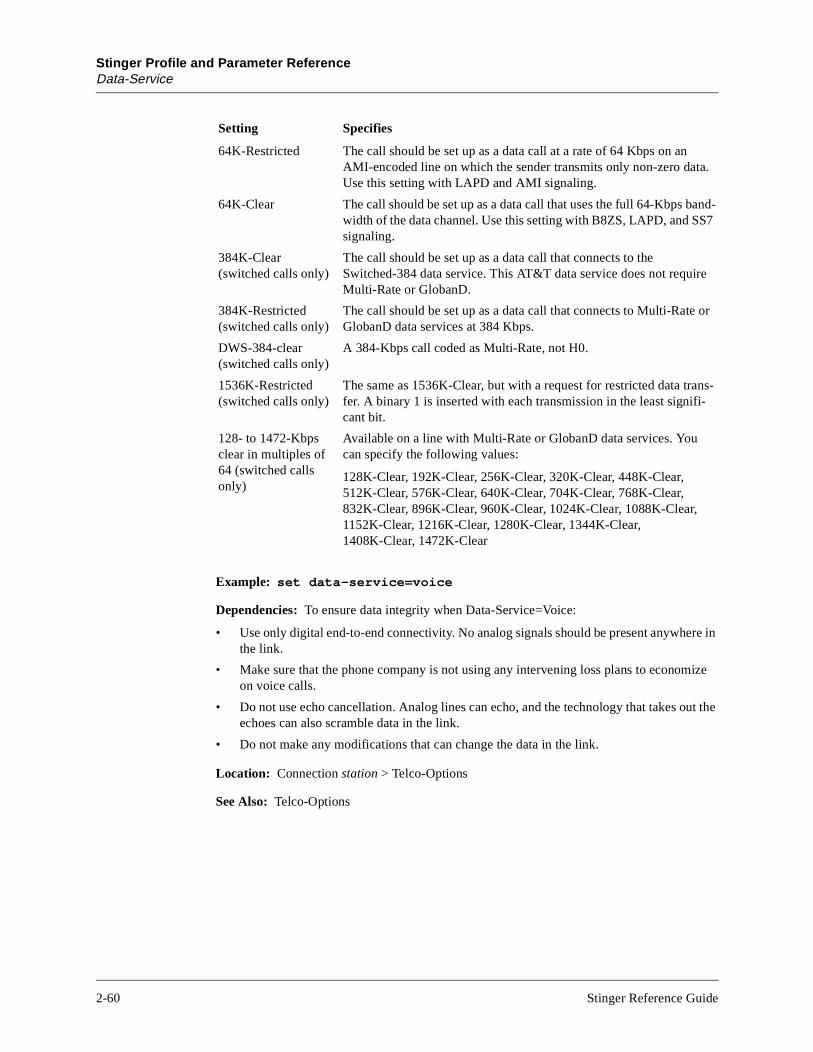
Stinger Profile and Parameter ReferenceData-Service
re in
ize
ut the
a.
and-S7
e
or
ns--
Example: set data-service=voice
Dependencies: To ensure data integrity when Data-Service=Voice:
• Use only digital end-to-end connectivity. No analog signals should be present anywhethe link.
• Make sure that the phone company is not using any intervening loss plans to economon voice calls.
• Do not use echo cancellation. Analog lines can echo, and the technology that takes oechoes can also scramble data in the link.
• Do not make any modifications that can change the data in the link.
Location: Connection station > Telco-Options
See Also: Telco-Options
64K-Restricted The call should be set up as a data call at a rate of 64 Kbps on anAMI-encoded line on which the sender transmits only non-zero datUse this setting with LAPD and AMI signaling.
64K-Clear The call should be set up as a data call that uses the full 64-Kbps bwidth of the data channel. Use this setting with B8ZS, LAPD, and Ssignaling.
384K-Clear (switched calls only)
The call should be set up as a data call that connects to the Switched-384 data service. This AT&T data service does not requirMulti-Rate or GlobanD.
384K-Restricted (switched calls only)
The call should be set up as a data call that connects to Multi-RateGlobanD data services at 384 Kbps.
DWS-384-clear (switched calls only)
A 384-Kbps call coded as Multi-Rate, not H0.
1536K-Restricted (switched calls only)
The same as 1536K-Clear, but with a request for restricted data trafer. A binary 1 is inserted with each transmission in the least significant bit.
128- to 1472-Kbps clear in multiples of 64 (switched calls only)
Available on a line with Multi-Rate or GlobanD data services. You can specify the following values:
128K-Clear, 192K-Clear, 256K-Clear, 320K-Clear, 448K-Clear, 512K-Clear, 576K-Clear, 640K-Clear, 704K-Clear, 768K-Clear, 832K-Clear, 896K-Clear, 960K-Clear, 1024K-Clear, 1088K-Clear, 1152K-Clear, 1216K-Clear, 1280K-Clear, 1344K-Clear, 1408K-Clear, 1472K-Clear
Setting Specifies
2-60 Stinger Reference Guide

Stinger Profile and Parameter ReferenceDate
ticates
s the
e of
Date
Description: A subprofile that shows the day of the week and the current system date.
Usage: With the Timedate profile as the working profile, list the Date subprofile. For example:
admin> list date[in TIMEDATE]weekday=Fridaymonth=Octoberday=18year=1996
You can then use the Set command to modify the settings in the subprofile.
admin> set weekday=Saturday
admin> set day=19
Note: You can also use the Date command to set the day of the week and the system date.
Example: set date day=19
Location: Timedate
See Also: Time
D-Channel-Enabled
Description: Indicates whether the unit enables D-channel (ISDN) signaling.
Usage: The D-Channel-Enabled setting is read only. Yes indicates that the unit supports D-channel signaling. No indicates that the unit does not support D-channel signaling.
Location: Base
See Also: Data-Call-Enabled, Multi-Rate-Enabled, R2-Signaling-Enabled, Switched-Enabled
Default-Status
Description: Specifies whether or not the Stinger displays the status screen by default when the user logs in.
Usage: Specify Yes or No. The default is No.
• Yes (the default) specifies that the Stinger displays the status screen when it authenthe profile.
• No specifies that the Stinger does not display the status screen when it authenticateprofile.
Example: set default-status=yes
Dependencies: Default-Status applies to Telnet and console logins. It does not apply to usthe Auth command.
Location: User name
Stinger Reference Guide 2-61

Stinger Profile and Parameter ReferenceDesired-State
s and
ations
et
ps
ps
See Also: Bottom-Status, Left-Status, Top-Status
Desired-State
Description: Specifies the desired administrative state of a device. The actual state of the device can differ from the desired state, as when a device is powering up, or if you change the desired state on a running slot. Changing the desired state does not force a device to the new state. It indicates that the Stinger should change the device state in a graceful manner.
Usage: Specify one of the following values:
• Admin-State-Down specifies that the addressed device should terminate all operationenter the down state.
• Admin-State-Up specifies that the addressed device should come up in normal opermode.
Dependencies: You can change the administrative state of a device by using the SNMP Scommands, or the Stinger Slot-d and Slot -u commands.
Example: set desired-state=admin-state-up
Location: Admin-State-Perm-If station, Admin-State-Phys-If {shelf-N slot-N N}
See Also: Desired-Trap-State, Device-Address, Inet-Profile-Type, Slot-Type, SNMP-Interface
Desired-Trap-State
Description: Indicates the desired up/down enable state of the interface.
Usage: The Desired-Trap-State setting is read only. The system can set it to one of the following values:
• Trap-State-Enabled indicates that an operator has specified that linkUp/linkDown trashould be generated for the interface.
• Trap-State-Disabled indicates that an operator has specified that linkUp/linkDown trashould not be generated for the interface.
Example: desired-trap-state=trap-state-enabled
Location: Admin-State-Perm-If station, Admin-State-Phys-If {shelf-N slot-N N}
See Also: Desired-State, Device-Address, Slot-Type, SNMP-Interface
2-62 Stinger Reference Guide

Stinger Profile and Parameter ReferenceDevice-Address
n
#1 the #2
Device-Address
Description: Specifies the address of a card.
Usage: The device address has the format {shelf slot item}, where:
In most cases, the Device-Address value is obtained from the system. However, you can clone a profile by reading an existing one and changing its device address. Use the List and Set commands to modify the Device-Address value. For example:
admin> list device-address[in ADMIN-STATE-PHYS-IF { shelf-1 slot-9 37 }]shelf=shelf-1slot=slot-9item-number=37
admin> set shelf=shelf-2
As an alternative, you can just use the Set command. For example:
admin> set device-address shelf=shelf-2
Location: Admin-State-Phys-If {shelf-N slot-N N}, Device-State {{shelf-N slot-N N} N}
See Also: Item-Number, Physical-Address, Shelf, Slot
Syntax element Description
shelf Specifies the shelf in which the item resides. If you are using a single-shelf system, the shelf number is always 1.
slot Specifies the number of the item’s expansion slot. Physical expansioslots are numbered from 1 to 16, starting with 1 for the slot just belowthe shelf controller. The slot value 17, controller, or c specifies the shelf controller card.
For example, to address the first slot on shelf 1:
{ 1 1 0 }
item Specifies an item on the slot card. Items are numbered starting with for the leftmost item on the card. An item number of 0 (zero) denotes entire slot. For example, to address SDSL port #48 on a card in slot on shelf 1:
{ 1 2 48 }
Stinger Reference Guide 2-63

Stinger Profile and Parameter ReferenceDevice-ID
e the ts or ate en the
Device-ID
Description: Specifies the identification number of the Access SS7 Gateway (ASG).
Usage: Accept the default of 0 (zero).
Dependencies: If Enabled=No in the SS7-Gateway profile, Device-ID does not apply.
Location: SS7-Gateway
See Also: Enabled, Primary-IP-Address, Primary-TCP-Port, Secondary-IP-Address, Secondary-TCP-Port
Device-State
Description: Indicates the current operational state of a device.
Usage: Device-State is read only. It can have one of the following values:
• Down-Dev-State indicates that the device is in a nonoperational state.
• Up-Dev-State indicates that the device is in normal operations mode.
• None-Dev-State indicates that the device does not currently exist.
Example: device-state=up-dev-state
Location: Device-State {{shelf-N slot-N N} N}
See Also: Reqd-State
Device-State (profile)
Description: A profile that stores the current state of a device. The Stinger does not storDevice-State profile in NVRAM, so the profile’s settings do not persist across system resepower cycles. The Device-State setting might differ from the Reqd-State setting during stchanges, such as when a device is being brought down. State changes are complete whDevice-State and the Reqd-State match.
Usage: To make Device-State the working profile, use the Read command, and specify ashelf, slot, item, and logical item number.
Example: To make Device-State the working profile for the device at interface address {{1 4 2}15}:
admin> read device-state {{1 4 2}15}DEVICE-STATE/{ { shelf-1 slot-4 2 } 15 } read
admin> list[in DEVICE-STATE/{ { shelf-1 slot-4 2 } 15 }]device-address*={ { shelf-1 slot-4 2 } 15 }device-state=down-dev-stateup-status=idle-up-statusreqd-state=up-reqd-state
2-64 Stinger Reference Guide
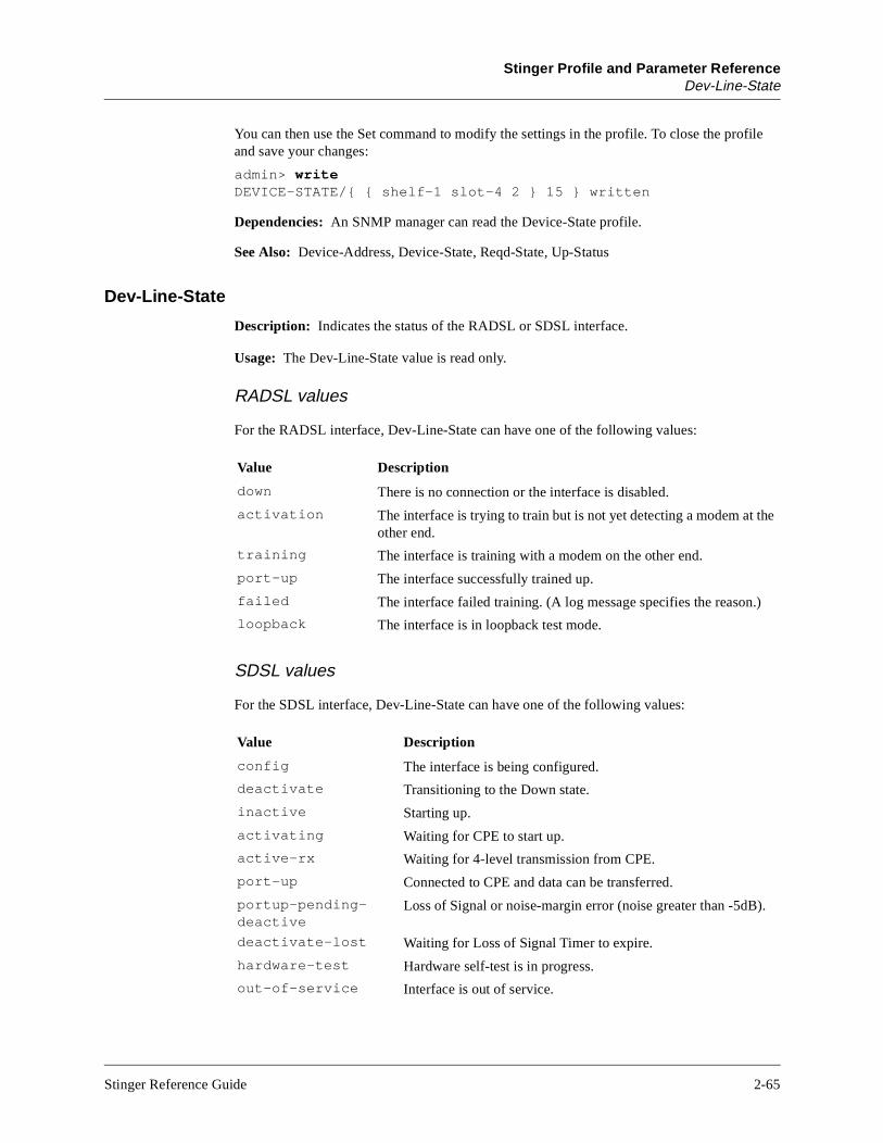
Stinger Profile and Parameter ReferenceDev-Line-State
You can then use the Set command to modify the settings in the profile. To close the profile and save your changes:
admin> writeDEVICE-STATE/{ { shelf-1 slot-4 2 } 15 } written
Dependencies: An SNMP manager can read the Device-State profile.
See Also: Device-Address, Device-State, Reqd-State, Up-Status
Dev-Line-State
Description: Indicates the status of the RADSL or SDSL interface.
Usage: The Dev-Line-State value is read only.
RADSL values
For the RADSL interface, Dev-Line-State can have one of the following values:
SDSL values
For the SDSL interface, Dev-Line-State can have one of the following values:
Value Description
down There is no connection or the interface is disabled.
activation The interface is trying to train but is not yet detecting a modem at the other end.
training The interface is training with a modem on the other end.
port-up The interface successfully trained up.
failed The interface failed training. (A log message specifies the reason.)
loopback The interface is in loopback test mode.
Value Description
config The interface is being configured.
deactivate Transitioning to the Down state.
inactive Starting up.
activating Waiting for CPE to start up.
active-rx Waiting for 4-level transmission from CPE.
port-up Connected to CPE and data can be transferred.
portup-pending-deactive
Loss of Signal or noise-margin error (noise greater than -5dB).
deactivate-lost Waiting for Loss of Signal Timer to expire.
hardware-test Hardware self-test is in progress.
out-of-service Interface is out of service.
Stinger Reference Guide 2-65

Stinger Profile and Parameter ReferenceDial-Number
s are don’t
) ce
Location: AL-DMT-Stat {shelf-N slot-N N} > Physical-Status, SDSL-Stat {shelf-N slot-N N} > Physical-Status
See Also: Down-Stream-Rate, Hardware-Ver, IF-Group-Index, Major-Firmware-Ver, Minor-Firmware-Ver, Physical-Address, Unit-Type, Up-Stream-Rate
Dial-Number
Description: Specifies the phone number used to dial the connection.
Usage: Specify the phone number of the remote station. You can enter up to 24 characters. The default is null.
Example: set dial-number=510-555-1212
Location: Connection station
See Also: CalledNumber
Dialout-Poison
Description: Specifies whether the Stinger should stop advertising its IP dialout routes (poison the routes) when no trunks are available.
The Yes setting solves a problem that can otherwise occur when two or more units on the same network are configured with redundant profiles and routes. If Dialout-Poison is set to No, and one of the redundant units loses its trunks temporarily, that unit continues to receive outgoing packets that should be forwarded to one of the other redundant units.
Usage: Specify Yes or No. The default is No.
• Yes specifies that the Stinger stops advertising its IP dialout routes if no trunks are available.
• No specifies that the Stinger continues to advertise its dialout routes, even if no trunkcurrently available. No is the appropriate setting unless you have redundant units or use dialout routes.
Example: set dialout-poison=no
tip-ring-detect Running a simple internal bit-error rate test (BERT) to detect correct tip-ring orientation.
forever-bert Running internal BERT to detect correct tip-ring orientation.
tip-wait1 Running internal BERT to detect correct tip-ring orientation.
tip-hunt Running internal BERT to detect correct tip-ring orientation.
tip-wait2 Running internal BERT to detect correct tip-ring orientation.
cell-delineation Attempting to recover ATM cells (idle cells as well as data cellsfrom the receiving octets. If recovery is successful, the interfatransitions to the Up state.
deactivate-wait Waiting to transition to the Down state.
Value Description
2-66 Stinger Reference Guide

Stinger Profile and Parameter ReferenceDirected-Broadcast-Allowed
nd its
ally,
ks
Location: IP-Global
See Also: RIP-Policy
Directed-Broadcast-Allowed
Description: Specifies whether the Stinger forwards directed broadcast traffic onto the interface and its network.
Usage: Specify Yes or No. The default is Yes.
• Yes specifies that the Stinger forwards directed broadcast traffic onto the interface anetwork.
• No specifies that the Stinger drops directed broadcast traffic that is not generated locpreventing it from propagating onto intermediary networks.
Example: set directed-broadcast-allowed=no
Dependencies: To protect all of the LAN interfaces against Denial of Services (DoS) attacthat use directed broadcast traffic, you must set Directed-Broadcast-Allowed=No in all IP-Interface profiles.
Location: IP-Interface {{shelf-N slot-N N} N}
See Also: ICMP-Reply-Directed-Bcast
Disabled-Count
Description: Indicates the number of devices that are in the down state.
Usage: The Disabled-Count setting is read only.
Example: disabled-count=0
Location: Device-Summary
See Also: Device-ID, Operational-Count, Total-Count
Domain-Name
Description: Specifies the local domain name for DNS lookups.
Usage: Specify the local domain name. The default is null.
Example: set domain-name=abc.com
Location: IP-Global
Stinger Reference Guide 2-67
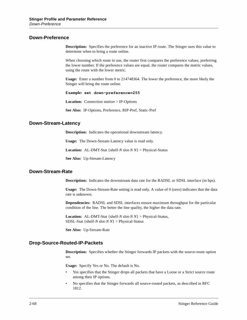
Stinger Profile and Parameter ReferenceDown-Preference
oute
Down-Preference
Description: Specifies the preference for an inactive IP route. The Stinger uses this value to determine when to bring a route online.
When choosing which route to use, the router first compares the preference values, preferring the lower number. If the preference values are equal, the router compares the metric values, using the route with the lower metric.
Usage: Enter a number from 0 to 214748364. The lower the preference, the more likely the Stinger will bring the route online.
Example: set down-preference=255
Location: Connection station > IP-Options
See Also: IP-Options, Preference, RIP-Pref, Static-Pref
Down-Stream-Latency
Description: Indicates the operational downstream latency.
Usage: The Down-Stream-Latency value is read only.
Location: AL-DMT-Stat {shelf-N slot-N N} > Physical-Status
See Also: Up-Stream-Latency
Down-Stream-Rate
Description: Indicates the downstream data rate for the RADSL or SDSL interface (in bps).
Usage: The Down-Stream-Rate setting is read only. A value of 0 (zero) indicates that the data rate is unknown.
Dependencies: RADSL and SDSL interfaces ensure maximum throughput for the particular condition of the line. The better the line quality, the higher the data rate.
Location: AL-DMT-Stat {shelf-N slot-N N} > Physical-Status, SDSL-Stat {shelf-N slot-N N} > Physical-Status
See Also: Up-Stream-Rate
Drop-Source-Routed-IP-Packets
Description: Specifies whether the Stinger forwards IP packets with the source-route option set.
Usage: Specify Yes or No. The default is No.
• Yes specifies that the Stinger drops all packets that have a Loose or a Strict source ramong their IP options.
• No specifies that the Stinger forwards all source-routed packets, as described in RFC1812.
2-68 Stinger Reference Guide

Stinger Profile and Parameter ReferenceDS3-ATM (profile)
e
lled.
d.
that card,
o ype
Example: set drop-source-routed-ip-packets=no
Location: IP-Global
See Also: IP-Global
DS3-ATM (profile)
Description: A profile containing configuration settings for a DS3-ATM card.
Usage: To make DS3-ATM the working profile and list its contents, use the Read and List commands. For example:
admin> read ds3-atm { 1 1 0 }DS3-ATM/{ shelf-1 slot-1 0 } read
admin> list[in DS3-ATM/{ shelf-1 slot-1 0 }]name=""physical-address*={ shelf-1 slot-1 0 }enabled=nospare-physical-address={ any-shelf any-slot 0 }sparing-mode=inactiveline-config={ 9 0 static { shelf-1 slot-1 0 } no-loopback no +
You can then use the Set command to modify the settings in the profile. To close the profile and save your changes, execute the Write command. For example:
admin> writeDS3-ATM/{ shelf-1 slot-1 0 } written
See Also: Enabled, Line-Config, Name, Physical-Address, Spare-Physical-Address, Sparing-Mode
DS3-ATM
Description: Specifies the action to take when the code image for an ATM-DS3 card is present in a Tar file.
Usage: Specify one of the following settings:
• Auto (the default) causes the system to load images for cards that are installed in thStinger, and to skip images for cards that are not installed.
• Load causes the system to load the image, even if there is no card of that type insta
• Skip causes the system to skip the image, even if there is a card of that type installe
Dependencies: A card is considered present in the system if a Slot-Type profile exists for card type. The system creates a Slot-Type profile when it first detects the presence of a and does not delete the profile unless the administrator uses the Slot –r command to permanently remove a card that is no longer installed in the system, or clears NVRAM. Tensure that the system does not load unnecessary images, use Slot –r to remove Slot-Tprofiles for cards that are no longer installed in the system.
Location: Load-Select
See Also: Enet, Enet2, SDSL, UDS3, Unknown-Cards
Stinger Reference Guide 2-69

Stinger Profile and Parameter ReferenceDS3-ATM-Stat
e.
DS3-ATM-Stat
Description: A profile that enables you to check the status of a DS3-ATM card.
Usage: To make DS3-ATM-Stat the working profile and list its contents, use the Read and List commands. For example:
admin> read ds3-atm-stat {1 7 1}DS3-ATM-STAT/{ shelf-1 slot-7 1 } read
admin> listphysical-address*={shelf-1 slot-7 1 }line-state=activef-bit-error-count=0p-bit-error-count=0cp-bit-error-count=0feb-error-count=0bpv-error-count=0loss-of-signal=Falseloss-of-frame=Falseyellow-receive=Falseais-receive=False
See Also: AIS-Receive, BPV-Error-Count, CP-Bit-Error-Count, F-Bit-Error-Count, FEB-Error-Count, Line-State, Loss-Of-Frame, Loss-Of-Signal, P-Bit-Error-Count, Physical-Address, Yellow-Receive
Duplex-Mode
Description: Specifies whether the physical Ethernet interface of the 100BaseT port on the Ethernet-2 card uses full-duplex or half-duplex mode.
Usage: Specify one of the following settings:
• Full-Duplex (the default) provides increased throughput.
• Half-Duplex enables operation with equipment that does not support full-duplex mod
Example: In the following example, the port is set to half-duplex mode:
admin> read ethernet { 1 7 4 }ETHERNET/{ shelf-1 slot-7 4 } read
admin> list[in ETHERNET/{ shelf-1 slot-7 4 }]interface-address*={ shelf-1 slot-7 4 }link-state-enabled=noenabled=yesether-if-type=utpbridging-enabled=noduplex-mode=full-duplex
admin> set duplex-mode=half
admin> writeETHERNET/{ shelf-1 slot-7 4 } written
Location: Ethernet {shelf-N slot-N N}
See Also: Ether-IF-Type, Enabled, Interface-Address, Link-State-Enabled
2-70 Stinger Reference Guide
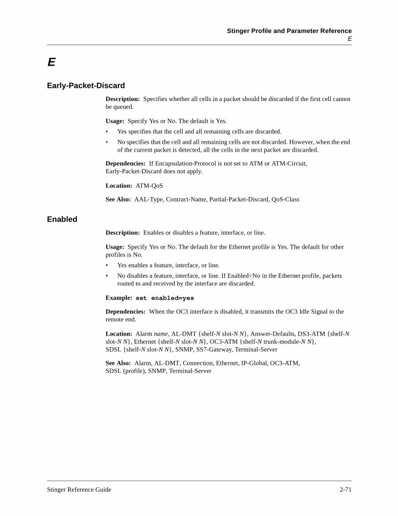
Stinger Profile and Parameter ReferenceE
e end
r
ts
e
E
Early-Packet-Discard
Description: Specifies whether all cells in a packet should be discarded if the first cell cannot be queued.
Usage: Specify Yes or No. The default is Yes.
• Yes specifies that the cell and all remaining cells are discarded.
• No specifies that the cell and all remaining cells are not discarded. However, when thof the current packet is detected, all the cells in the next packet are discarded.
Dependencies: If Encapsulation-Protocol is not set to ATM or ATM-Circuit, Early-Packet-Discard does not apply.
Location: ATM-QoS
See Also: AAL-Type, Contract-Name, Partial-Packet-Discard, QoS-Class
Enabled
Description: Enables or disables a feature, interface, or line.
Usage: Specify Yes or No. The default for the Ethernet profile is Yes. The default for otheprofiles is No.
• Yes enables a feature, interface, or line.
• No disables a feature, interface, or line. If Enabled=No in the Ethernet profile, packerouted to and received by the interface are discarded.
Example: set enabled=yes
Dependencies: When the OC3 interface is disabled, it transmits the OC3 Idle Signal to thremote end.
Location: Alarm name, AL-DMT {shelf-N slot-N N}, Answer-Defaults, DS3-ATM {shelf-N slot-N N}, Ethernet {shelf-N slot-N N}, OC3-ATM {shelf-N trunk-module-N N}, SDSL {shelf-N slot-N N}, SNMP, SS7-Gateway, Terminal-Server
See Also: Alarm, AL-DMT, Connection, Ethernet, IP-Global, OC3-ATM, SDSL (profile), SNMP, Terminal-Server
Stinger Reference Guide 2-71

Stinger Profile and Parameter ReferenceEncapsulation-Protocol
esent
e
lled.
d.
that card,
o ype
Encapsulation-Protocol
Description: Specifies the encapsulation method to use for the connection. Both sides of the connection must support the specified encapsulation method. Usually, encapsulation protocols have their own configuration options within the subprofile of a Connection profile.
Usage: Specify one of the following values:
• ATM for an Asynchronous Transfer Mode (ATM) connection in routed mode. Packetsarriving on the connection are routed at OSI layer 3.
• ATM-Circuit (the default) for point-to-point switch-through ATM connections.
Example: set encapsulation-protocol=atm
Location: Connection station
Enet
Description: Specifies the action to take when the code image for an Ethernet card is prin a Tar file.
Usage: Specify one of the following settings:
• Auto (the default) causes the system to load images for cards that are installed in thStinger, and to skip images for cards that are not installed.
• Load causes the system to load the image, even if there is no card of that type insta
• Skip causes the system to skip the image, even if there is a card of that type installe
Dependencies: A card is considered present in the system if a Slot-Type profile exists for card type. The system creates a Slot-Type profile when it first detects the presence of a and does not delete the profile unless the administrator uses the Slot –r command to permanently remove a card that is no longer installed in the system, or clears NVRAM. Tensure that the system does not load unnecessary images, use Slot –r to remove Slot-Tprofiles for cards that are no longer installed in the system.
Location: Load-Select
See Also: DS3-ATM, Enet2, SDSL, UDS3, Unknown-Cards
2-72 Stinger Reference Guide
Stinger Profile and Parameter ReferenceEnet2
e
lled.
d.
that card,
o ype
anager
ss of
munity
s
Enet2
Description: Specifies the action to take when the code image for an Ethernet-2 card is present in a Tar file.
Usage: Specify one of the following settings:
• Auto (the default) causes the system to load images for cards that are installed in thStinger, and to skip images for cards that are not installed.
• Load causes the system to load the image, even if there is no card of that type insta
• Skip causes the system to skip the image, even if there is a card of that type installe
Dependencies: A card is considered present in the system if a Slot-Type profile exists for card type. The system creates a Slot-Type profile when it first detects the presence of a and does not delete the profile unless the administrator uses the Slot –r command to permanently remove a card that is no longer installed in the system, or clears NVRAM. Tensure that the system does not load unnecessary images, use Slot –r to remove Slot-Tprofiles for cards that are no longer installed in the system.
Location: Load-Select
See Also: DS3-ATM, Enet, SDSL, UDS3, Unknown-Cards
Enforce-Address-Security
Description: Specifies whether the Stinger should validate the IP address of an SNMP manager attempting to access the unit. If address security is not enforced, any SNMP mwho presents the appropriate community name is allowed in.
Usage: Specify Yes or No. The default is No.
• Yes specifies that, before allowing access, the Stinger compares the source IP addrean SNMP manager to the host addresses specified by Read-Access-Hosts and Write-Access-Hosts.
• No specifies that the Stinger does not compare IP addresses, but uses only the comname to validate SNMP access.
Example: set enforce-address-security=yes
Dependencies: Read-Access-Hosts and Write-Access-Hosts do not restrict access unlesEnforce-Address-Security=Yes.
Location: SNMP
See Also: Read-Access-Hosts, Write-Access-Hosts
Stinger Reference Guide 2-73

Stinger Profile and Parameter ReferenceError
se5)
EE
Error
Description: A read-only profile that provides information about any errors that occur when the Stinger is running.
Usage: Use the Read and List commands to make Error the working profile and list its contents. For example:
admin> read error 1ERROR/1 read
admin> list[in ERROR/1]is-post=notype=100slot=17user-profile=""ip-address=0.0.0.0stack-trace=[ 0 0 0 0 0 0 ]loadname=unitsrindex*=1shelf=1
See Also: Index, IP-Address, IS-Post, Loadname, Shelf, Slot, Stack-Trace, User-Profile
Error-Count
Description: Indicates the number of errors experienced by a line since the last reset.
Usage: Use the List command to display the number of errors. For example:
admin> list error-count[in SDSL-STAT/{ shelf-1 slot-1 1 }:error-count] error-count=0
Location: SDSL-Stat {shelf-N slot-N N}
See Also: SDSL-Stat
Ether-IF-Type
Description: Indicates the type of physical Ethernet interface in use.
Usage: The Ether-IF-Type setting is read only. It can have one of the following values:
• UTP indicates unshielded twisted pair (thin Ethernet) as specified in IEEE 802 (10BaEthernet.
• AUI (Auxiliary Unit Interface) indicates a thick Ethernet transceiver as specified in IE802.3 (10BaseT) Ethernet.
• Coax indicates coaxial cable.
Location: Ethernet {shelf-N slot-N N}
See Also: Enabled, Interface-Address, Link-State, Link-State-Enabled, MAC-Address
2-74 Stinger Reference Guide

Stinger Profile and Parameter ReferenceEther-Info
Ether-Info
Description: A profile that specifies the MAC address and link state of an Ethernet interface. The Ether-Info profile is created when the Ethernet card enters an active state, and deleted when the slot is brought down. The contents of the profile are not written to NVRAM.
Usage: Use the Read and List commands to make Ether-Info the working profile and list its contents. For example:
admin> read ether-info { 1 2 1}ETHER-INFO/{ shelf-1 slot-2 1 } read
admin> list[in ETHER-INFO/{ shelf-1 slot-2 1 }]interface-address*={ shelf-1 slot-2 1 }mac-address=00:c0:7b:68:ef:98link-state=up
Dependencies: The Ether-Info profile is read only.
See Also: Interface-Address, Link-State, MAC-Address
Ethernet
Description: A profile that defines the physical components of a system Ethernet interface.
Usage: To make Ethernet the working profile and list its contents:
admin> read ethernet {1 c 1}ETHERNET/{ shelf-1 controller 1 } read
admin> list[in ETHERNET/{ shelf-1 controller 1 }]interface-address*={ shelf-1 controller 1 }ether-if-type=utpenabled=yeslink-state-enabled=noduplex-mode=full-duplex
You can then use the Set command to modify the settings in the profile. To close the profile and save your changes, execute the Write command. For example:
admin> writeETHERNET/{ shelf-1 controller 1 } written
See Also: Duplex-Mode, Ether-IF-Type, Enabled, Interface-Address, Link-State-Enabled
Stinger Reference Guide 2-75
Stinger Profile and Parameter ReferenceEvent
line.
ritten ntil at
unread
tten an
list
Event
Description: Specifies an alarm event that triggers the actions indicated by the Action subprofile.
Usage: Specify one of the following values:
• Power-Fail specifies that a redundant power supply fails.
• Fan-Fail specifies that a redundant fan fails.
• Line-State-Change (the default) specifies that the Stinger detects a state change in a
• Slot-State-Change specifies that the Stinger detects a state change in a slot.
Example: set event=fan-fail
Location: Alarm name
See Also: Action
Event-Overwrite-Enabled
Description: Specifies whether the system generates a trap when a new event has overwan unread event. Once sent, additional overwrites will not cause another trap to be sent uleast one table's worth of new events have occurred.
Usage: Specify Yes or No. The default is Yes.
• Yes specifies that the system generates a trap when a new event has overwritten an event.
• No specifies that the system does not generate a trap when a new event has overwriunread event.
Example: set event-overwrite-enabled=no
Location: Trap host-name
See Also: RADIUS-Change-Enabled
External-Auth
Description: A profile containing configuration options for RADIUS.
Usage: Use the Read and List commands to make External-Auth the working profile andits contents. For example:
admin> read external-authEXTERNAL-AUTH read
admin> list[in EXTERNAL-AUTH]auth-type=radiusacct-type=nonerad-auth-client={ 200.168.6.153 0.0.0.0 0.0.0.0 1645 0 +rad-acct-client={ 0.0.0.0 0.0.0.0 0.0.0.0 0 0 "" 0 0 +rad-id-source-unique=system-uniquerad-id-space=unifiedlocal-profiles-first=lpf-yesnoattr6-use-termsrv=yes
2-76 Stinger Reference Guide

Stinger Profile and Parameter ReferenceExt-Tsrv
You can then use the Set command to modify the settings in the profile. To close the profile and save your changes:
admin> writeEXTERNAL-AUTH written
See Also: Acct-Type, Auth-Type, Local-Profiles-First, NoAttr6-Use-Termsrv, Rad-Acct-Client, Rad-Auth-Client, Rad-ID-Source-Unique, Rad-ID-Space
Ext-Tsrv
Description: A read-only profile that stores banner and hosts information loaded from RADIUS.
Usage: The Refresh -t command requests initial-banner and banner/hosts information from RADIUS as two separate requests, which independently update the Ext-Tsrv profile. If the information changes the profile contents, the system notifies the slot cards and they update their information.
Use the Read and List commands to make Ext-Tsrv the working profile and list its contents. For example:
admin> read ext-tsrvEXT-TSRV read
admin> list init-banner[in EXT-TSRV:init-banner]init-banner[1]=""init-banner[2]=""init-banner[3]=""init-banner[4]=""init-banner[5]=""init-banner[6]=""init-banner[7]=""init-banner[8]=""init-banner[9]=""init-banner[10]=""init-banner[11]=""init-banner[12]=""init-banner[13]=""init-banner[14]=""init-banner[15]=""init-banner[16]=""
admin> list banner[in EXT-TSRV:banner]banner[1]=""banner[2]=""banner[3]=""banner[4]=""banner[5]=""banner[6]=""banner[7]=""banner[8]=""banner[9]=""
Stinger Reference Guide 2-77

Stinger Profile and Parameter ReferenceExt-Tsrv
banner[10]=""banner[11]=""banner[12]=""banner[13]=""banner[14]=""banner[15]=""banner[16]=""
admin> list hosts-info[in EXT-TSRV:hosts-info]hosts-info[1]={ 0.0.0.0 "" }hosts-info[2]={ 0.0.0.0 "" }hosts-info[3]={ 0.0.0.0 "" }hosts-info[4]={ 0.0.0.0 "" }hosts-info[5]={ 0.0.0.0 "" }hosts-info[6]={ 0.0.0.0 "" }hosts-info[7]={ 0.0.0.0 "" }hosts-info[8]={ 0.0.0.0 "" }hosts-info[9]={ 0.0.0.0 "" }hosts-info[10]={ 0.0.0.0 "" }
See Also: Banner, Hosts-Info N, Init-Banner N
2-78 Stinger Reference Guide

Stinger Profile and Parameter ReferenceF
d to
y
F
Facility
Description: Specifies the Syslog daemon facility code for messages logged from the Stinger. For detailed information, see the syslog.conf manual page entry on the UNIX Syslog server.
Usage: Specify one of the following values:
• Local0 (the default)
• Local1
• Local2
• Local3
• Local4
• Local5
• Local6
• Local7
Example: set facility=local0
Dependencies: The Facility value in the Log profile affects all data streams. The Facility value in each Auxiliary-Syslog subprofile affects the individual data stream directethe device specified by the Host value, and overrides the value in the Log profile.
Location: Log, Log > Auxiliary-Syslog > Auxiliary-Syslog N
See Also: Host, Syslog-Enabled
Far-End-CRC
Description: Indicates the number of Cyclic Redundancy Check (CRC) errors detected bCPE’s ADSL Transceiver Unit (ATU).
Usage: The Far-End-CRC value is read only.
Example: far-end-crc=0
Location: AL-DMT-Stat {shelf-N slot-N N} > Physical-Statistic
See Also: Far-End-FEC, Far-End-HEC
Stinger Reference Guide 2-79

Stinger Profile and Parameter ReferenceFar-End-dB-Attenuation
Far-End-dB-Attenuation
Description: Indicates the attenuation of the signal received from the CPE.
Usage: The Far-End-dB-Attenuation setting is read only.
Location: SDSL-Stat {shelf-N slot-N N} > Physical-Statistic
See Also: Line-Quality, Line-Up-Timer, Physical-Address, RX-Signal-Present, Self-Test, Up-Down-Cntr
Far-End-FEC
Description: Indicates the number of Forward Error Correction (FEC) errors detected by CPE’s ADSL Transceiver Unit (ATU).
Usage: The Far-End-FEC value is read only.
Example: far-end-fec=0
Location: AL-DMT-Stat {shelf-N slot-N N} > Physical-Statistic
See Also: Far-End-CRC, Far-End-HEC
Far-End-HEC
Description: Indicates the number of Header Error Checksum (HEC) errors detected by CPE’s ADSL Transceiver Unit (ATU).
Usage: The Far-End-HEC value is read only.
Example: far-end-hec=0
Location: AL-DMT-Stat {shelf-N slot-N N} > Physical-Statistic
See Also: Far-End-CRC, Far-End-FEC
Fast-Path-Config
Description: A subprofile that enables you to define minimum, maximum, and planned upstream and downstream bit rates for a rate-adaptive connection on a fast channel.
Usage: With AL-DMT as the working profile, list the Fast-Path-Config subprofile. For example:
admin> list fast-path-config[in AL-DMT/{ shelf-1 slot-4 1 }:fast-path-config]min-bitrate-up=10min-bitrate-down=50max-bitrate-up=1000max-bitrate-down=8000planned-bitrate-up=200planned-bitrate-down=1000
2-80 Stinger Reference Guide

Stinger Profile and Parameter ReferenceF-Bit-Error-Count
You can then use the Set command to modify the settings in the subprofile. To close the subprofile and return to a higher context in the working profile:
admin> list ..
Location: AL-DMT {shelf-N slot-N N}
See Also: Max-Bitrate-Down, Max-Bitrate-Up, Min-Bitrate-Down, Min-Bitrate-Up, Planned-Bitrate-Down, Planned-Bitrate-Up
F-Bit-Error-Count
Description: Indicates the number of framing bit errors received since the last time the unit was reset.
Usage: The F-Bit-Error-Count value is read only.
Example: f-bit-error-count=0
Location: DS3-ATM-Stat {shelf-N slot-N N}
See Also: AIS-Receive, BPV-Error-Count, CP-Bit-Error-Count, FEB-Error-Count, Line-State, Loss-Of-Frame, Loss-Of-Signal, P-Bit-Error-Count, Physical-Address, Yellow-Receive
FEB-Error-Count
Description: Indicates the number of far-end block errors received since the last time the unit was reset.
Usage: The FEB-Error-Count value is read only.
Example: feb-error-count=0
Location: DS3-ATM-Stat {shelf-N slot-N N}
See Also: AIS-Receive, BPV-Error-Count, CP-Bit-Error-Count, F-Bit-Error-Count, Line-State, Loss-Of-Frame, Loss-Of-Signal, P-Bit-Error-Count, Physical-Address, Yellow-Receive
FIFO-Overflow-Counter
Description: Indicates the number of cells dropped due to FIFO overflow.
Usage: The FIFO-Overflow-Counter value is read only.
Example: fifo-overflow-counter=0
Location: OC3-ATM-Stat {shelf-N trunk-module-N N}
See Also: HEC-Cell-Drop-Counter
Stinger Reference Guide 2-81

Stinger Profile and Parameter ReferenceFirmware-Startup-Stage
ven h
Firmware-Startup-Stage
Description: Indicates the current firmware state.
Usage: The Firmware-Startup-Stage value is read only.
Location: SDSL-Stat {shelf-N slot-N N} > Physical-Statistic
See Also: Far-End-dB-Attenuation, Line-Quality, Line-Up-Timer, Physical-Address, RX-Signal-Present, Self-Test, Up-Down-Cntr
Firmware-Ver
Description: Indicates the version number of the Line Interface Module (LIM) firmware.
Usage: The Firmware-Ver value is read only.
Example: firmware-ver=1.4.1
Location: AL-DMT-Stat {shelf-N slot-N N} > Physical-Status
Flow-Control
Description: Specifies the flow control method used on the serial port.
Usage: Specify one of the following values:
• None (the default)
• Xon-Xoff
• Hardware-Handshake
Example: set flow-control=xon-xoff
Location: Serial {shelf-N slot-N N}
See Also: Serial
Force-56Kbps
Description: Specifies whether the Stinger uses only the 56-Kbps portion of a channel, ewhen all 64 Kbps appear to be available. You need not set this value for calls within NortAmerica.
Usage: Specify Yes or No. The default is No.
• Yes causes the Stinger to use only the 56-Kbps portion of a channel.
• No specifies that the Stinger uses the full 64-Kbps bandwidth, if it is available.
Example: set force-56kbps=no
Location: Answer-Defaults, Connection station > Telco-Options
See Also: Data-Service, Telco-Options
2-82 Stinger Reference Guide

Stinger Profile and Parameter ReferenceFramed-Only
Framed-Only
Description: Specifies whether an incoming call must use a framed protocol.
Usage: Specify Yes or No. The default is No.
• Yes specifies that an incoming call must use a framed protocol.
• No specifies that an incoming call need not use a framed protocol.
Example: set framed-only=yes
Location: Connection station
See Also: Encapsulation-Protocol
Framer-Mode
Description: Specifies the DS3 ATM framer mode.
Usage: Specify one of the following values:
• C-Bit-ADM specifies free-running and fixed-stuffing C-Bit-ADM mode.
• C-Bit-PLCP (the default) specifies free-running and fixed-stuffing C-Bit-PLCP mode.
• C-Bit-ADM-Loop-Timed specifies loop-timed C-Bit-ADM mode.
• C-Bit-PLCP-Loop-Timed specifies loop-timed C-Bit-PLCP mode.
• C-Bit-ADM-Frame-Locked specifies frame-locked C-Bit-ADM mode.
• C-Bit-PLCP-Frame-Locked specifies frame-locked C-Bit-PLCP mode.
Example: set framer-mode=c-bit-plcp-frame-locked
Location: DS3-ATM {shelf-N shelf-N N} > Line-Config
See Also: Framer-Rate
Framer-Rate
Description: Specifies the framing to use on the link.
Usage: Currently, the only supported value is STS-3C, which is used for a 155.52-Mbps interface in the U.S. as well as the equivalent European 155 Mbps interface (STM-1).
Location: OC3-ATM {shelf-N trunk-module-N N} > Line-Config
Frequency-Justification-Count
Description: Indicates the number of frequency justification operations.
Usage: The Frequency-Justification-Count value is read only.
Example: frequency-justification-count=0
Location: OC3-ATM-Stat {shelf-N trunk-module-N N}
Stinger Reference Guide 2-83
Stinger Profile and Parameter ReferenceG
G
Gateway-Address
Description: Specifies the address of the next-hop router the Stinger uses to reach the destination address specified by a static route. A next-hop router is directly connected to the Stinger on the Ethernet, or is one hop away on a WAN link.
Usage: Specify the IP address of the router the Stinger uses to reach the target host for the route. The default is 0.0.0.0.
Example: set gateway-address=10.207.23.1
Location: IP-Route name
2-84 Stinger Reference Guide

Stinger Profile and Parameter ReferenceH
H
Hardware-Level
Description: Indicates a one- or two-character string representing the hardware revision level of the card.
Usage: The Hardware-Level setting is read only. A value of 0 (zero) means that the revision level is unknown.
Location: Base, Slot-Info {shelf-N slot-N N}
See Also: Software-Level
Hardware-Rework-Count
Description: Indicates the number of times the card has been reworked.
Usage: The Hardware-Rework-Count setting is read only.
Location: Slot-Info {shelf-N slot-N N}
See Also: Hardware-Level
Hardware-Ver
Description: Indicates the hardware version of the Line Interface Module (LIM).
Usage: The Hardware-Ver setting is read only.
Location: AL-DMT-Stat {shelf-N slot-N N} > Physical-StatusSDSL-Stat {shelf-N slot-N N} > Physical-Status
See Also: Major-Firmware-Ver, Minor-Firmware-Ver
HEC-Cell-Drop-Counter
Description: Indicates the number of cells dropped by HEC processing.
Usage: The HEC-Cell-Drop-Counter value is read only.
Example: hec-cell-drop-counter=0
Location: OC3-ATM-Stat {shelf-N trunk-module-N N}
See Also: FIFO-Overflow-Counter
Stinger Reference Guide 2-85
Stinger Profile and Parameter ReferenceHigh-Tx-Output
s:
ress
21
e host
in ed
High-Tx-Output
Description: Specifies whether the DS3 cable length is more than 255 feet.
Usage: Specify Yes or No. The default is No.
• Yes specifies that the DS3 cable length is more than 255 feet.
• No specifies that the DS3 cable length less than 255 feet.
Example: set high-tx-output=yes
Location: DS3-ATM {shelf-N slot-N N} > Line-Config
Host
Description: Specifies the DNS hostname or address of a host on the network, as follow
• In the Log profile and Auxiliary-Syslog subprofile, the Host value specifies the IP addof a UNIX Syslog server.
• In the Terminal-Server profile, the Host value specifies the name, IP address, or X.1address of the host to use for immediate service. When the Stinger authenticates a connection, it immediately directs the data stream to the specified host.
Usage: Your usage depends on the profile:
• For the Log profile and Auxiliary-Syslog subprofile, specify the IP address of a UNIXSyslog server. The default is 0.0.0.0.
• For the Terminal-Server profile, specify the name, IP address, or X.121 address of thto use for immediate service. The default is a null string or null address.
Dependencies: The Host value in the Log profile affects all data streams. The Host valueeach Auxiliary-Syslog subprofile affects the individual data stream directed to the specifidevice, and overrides the value in the Log profile.
Location: Log, Log > Auxiliary-Syslog > Auxiliary-Syslog N,Terminal-Server > Immediate-Mode-Options
See Also: Facility, Immediate-Mode-Options, Port, Save-Level, Save-Number, Service, Syslog-Enabled
Host-N (N=1–4)
Description: Specifies the IP addresses of the Telnet hosts the Stinger displays in the terminal-server menu. You can specify up to four host addresses. If the user cannot use the terminal-server command-line interface, the hosts you specify are the only ones to which the user has access.
Usage: Specify an IP address in dotted decimal notation. Separate the optional subnet mask from the address by entering a forward slash. The default is 0.0.0.0.
Example: set host-1=10.1.2.3/29
Dependencies: If terminal services are disabled, Host-N does not apply. In addition, the Stinger ignores the host addresses if Remote-Configuration=Yes. If you want to specify more than four addresses, you must do so in RADIUS.
2-86 Stinger Reference Guide

Stinger Profile and Parameter ReferenceHost-Address
es
,
Location: Terminal-Server > Menu-Mode-Options
See Also: Menu-Mode-Options, Remote-Configuration
Host-Address
Description: Specifies the address to which the Stinger sends trap-PDUs.
Usage: Specify an IP address in dotted decimal notation. The default is 0.0.0.0. If Host-Address is set to 0.0.0.0 and DNS (or YP/NIS) is supported, the Stinger looks up the host address and sends trap-PDUs. If Host-Address is set to 0.0.0.0 and Community-Name is null, traps are disabled.
Example: set host-address=10.2.3.4/24
Location: Trap host-name
See Also: Alarm-Enabled, Community-Name, Host-Name, Port-Enabled, Security-Mode
Host-Name
Description: In the Trap profile, specifies the hostname of a station running SNMP manager utilities.
Usage: Specify a hostname of up to 16 characters. The default is null.
Example: set host-name=sparky
Dependencies: Consider the following:
• If Host-Address is set, the Stinger does not use the Host-Name value.
• The Stinger sends SNMP traps to the host you specify.
• When DNS or YP/NIS is supported, but Host-Address is not specified, the Stinger usthe hostname to look up the LAN address of the SNMP manager.
Location: Trap host-name
See Also: Alarm-Enabled, Community-Name, Domain-Name, Host-Address, IP-AddressPort-Enabled, Sec-Domain-Name, Security-Mode
Hosts-Info N
Description: Specifies up to ten IP addresses and hostnames for the menu displayed in Terminal-Server menu mode.
Usage: The Hosts-Info setting is read only.
Example: hosts-info [1]={ 200.50.40.5 }
Location: Ext-Tsrv
See Also: Banner N, Init-Banner N
Stinger Reference Guide 2-87
Stinger Profile and Parameter ReferenceI
uests.
he
I
ICMP-Reply-Directed-Bcast
Description: Specifies whether the Stinger responds to directed-broadcast ICMP echo requests.
Usage: Specify Yes or No. The default is Yes.
• Yes specifies that the Stinger responds to directed-broadcast ICMP echo requests.
• No specifies that the Stinger does not respond to directed-broadcast ICMP echo req
Example: set icmp-reply-directed-bcast=no
Location: IP-Global
See Also: Directed-Broadcast-Allowed
ID-Auth-Prefix
Description: Specifies the string inserted as a prefix to the phone number presented to tRADIUS server in CLID or DNIS authentication requests.
Usage: Specify up to 16 characters. The default is null.
Example: set id-auth-prefix=test
Location: External-Auth > Rad-Auth-Client
See Also: Auth-ID-Fail-Return-Busy, Auth-ID-Timeout-Return-Busy
Idle-Cell-Counter
Description: Indicates the total number of idle cells received by the unit.
Usage: The Idle-Cell-Counter value is read only.
Example: idle-cell-counter=0
Location: OC3-ATM-Stat {shelf-N trunk-module-N N}
See Also: Valid-Cell-Counter
2-88 Stinger Reference Guide
Stinger Profile and Parameter ReferenceIdle-Logout
Idle-Logout
Description: Specifies the number of seconds a Telnet session can remain logged in with no keyboard activity.
Usage: Specify a number of seconds. The default is 0 (zero), which specifies that the station can remain logged in indefinitely.
Example: set idle-logout=60
Location: System, User name
See Also: Auto-Logout, Idle-Timer
Idle-Timer
Description: Specifies the number of seconds the Stinger waits before clearing a call when a session is inactive.
Usage: Specify a number from 0 to 65535. The default setting is 120 seconds. Setting a value of 0 (zero) disables the idle timer, so that an idle call is maintained indefinitely.
Example: set idle-timer=30
Dependencies: The Idle-Timer value applies only to sessions in which the Stinger transmits data in packets through the router to the WAN connection. Idle-Timer does not apply to nailed-up or terminal-server connections. For a terminal-server connection, use TS-Idle-Timer.
Location: Answer-Defaults > Session-Info, Connection station > Session-Options
See Also: Password, Session-Options, TS-Idle-Timer
IF-Group-Index
Description: Indicates the SNMP interface group index assigned to the line.
Usage: The IF-Group-Index setting is read only.
Location: AL-DMT-Stat {shelf-N slot-N N} > Physical-StatusSDSL-Stat {shelf-N slot-N N} > Physical-Status
See Also: Dev-Line-State, Down-Stream-Rate, Hardware-Ver, Major-Firmware-Ver, Minor-Firmware-Ver, Physical-Address, Unit-Type, Up-Stream-Rate
Stinger Reference Guide 2-89

Stinger Profile and Parameter ReferenceIF-Remote-Address
that
.
MP e least figure
IF-Remote-Address
Description: Specifies the IP address of the numbered interface at the remote end of a link.
Usage: Specify the IP address of the numbered interface in dotted decimal notation. The default is 0.0.0.0.
Dependencies: For IF-Remote-Address to apply, you must enable IP for the Connection profile.
Location: Connection station > IP-Options
See Also: IP-Options
Ignore-Def-Route
Description: Specifies whether the Stinger ignores the default route when applying RIP updates to its routing table. The default route specifies a static route to another IP router, which is often a local router. When you configure the Stinger to ignore the default route, RIP updates do not modify the default route in the Stinger routing table.
Usage: Specify Yes or No. The default is No.
• Yes specifies that the Stinger ignores advertised default routes. Lucent recommendsyou specify Yes.
• No specifies that the Stinger can modify its default route on the basis of RIP updates
Example: set ignore-def-route=yes
Location: IP-Global
See Also: Client-Default-Gateway, RIP
Ignore-ICMP-Redirects
Description: Specifies whether the Stinger processes incoming ICMP redirect packets. ICredirects are one of the oldest route-discovery mechanisms on the Internet, and one of thsecure, because they can be used to redirect packets dynamically. Most secure sites conthe Stinger to ignore redirect packets.
Usage: Specify Yes or No. The default is No.
• Yes causes the Stinger to ignore ICMP redirect packets.
• No causes the Stinger to process ICMP redirect packets.
Example: set ignore-icmp-redirects=yes
Location: IP-Global
See Also: Preference, RIP-Pref, Static-Pref
2-90 Stinger Reference Guide

Stinger Profile and Parameter ReferenceImmediate-Mode-Options
Immediate-Mode-Options
Description: A subprofile containing terminal-server configuration options for immediate mode. In immediate mode, the Stinger makes a connection to an IP host immediately upon login.
Usage: With Terminal-Server as the working profile, list the Immediate-Mode-Options subprofile. For example:
admin> list immediate-mode-options[in TERMINAL-SERVER:immediate-mode-options]service=nonetelnet-host-auth=nohost=""port=0
You can then use the Set command to modify the settings in the subprofile. To close the subprofile and return to a higher context in the working profile:
admin> list ..
Location: Terminal-Server
See Also: Host, Port, Service, Telnet-Host-Auth
Index
Description: Indicates the internal index of the entry.
Usage: The Index setting is read only.
Location: Error index
See Also: Interface-Address
Inet-Profile-Type
Description: Specifies whether the nailed-up profile is a local profile or a RADIUS profile.
Usage: The Inet-Profile-Type setting is read only. The number 0 (zero) indicates a local profile. The number 1 (one) indicates a RADIUS profile.
Example: inet-profile-type=1
Location: Admin-State-Perm-If station
See Also: Desired-State, Desired-Trap-State, Device-Address, SNMP-Interface, Station
Stinger Reference Guide 2-91

Stinger Profile and Parameter ReferenceInit-Banner N
Init-Banner N
Description: Specifies the initial-banners for terminal-server logins, downloaded from RADIUS.
Usage: The Init-Banner setting is read only.
Example: init-banner [1]="Welcome"
Location: Ext-Tsrv
See Also: Banner N, Hosts-Info N
Initial-ADSL-Ver
Description: Indicates the number of changes made to the Alcatel Proprietary Exchange phase in this version of the software. Both ends of the connection must agree on the value of Initial-ADSL-Ver for the chip sets to take advantage of the advanced functionality supported by Alcatel equipment.
Usage: The Initial-ADSL-Ver value is read only. Zero is its current value.
Example: initial-adsl-ver=0
Location: AL-DMT-Stat {shelf-N slot-N N} > Physical-Status
See Also: ANSI-ADSL-Ver
Interface-Address
Description: Identifies an interface address in the following format:
{{shelf slot item} logical-item }
This format specifies the physical address and a logical item. For information about the physical address format, see the description for Physical-Address. The logical item number is 0 (zero), except when the device is further divided.
Usage: In most cases, the Interface-Address value is obtained from the system. However, you can clone a profile by reading an existing one and changing its device address. To modify the value, use the List and Set commands. For example:
admin> list interface-address[in ETHERNET/{ { shelf-1 slot-8 } 5 }:interface-address] physical-address={ shelf-1 slot-8 5 }logical-item=0
admin> set logical-item=11
Alternatively, just use the Set command:
admin> set interface-address logical-item=11
Location: Ethernet {shelf-N slot-N N}, IP-Interface {{shelf-N slot-N N}
See Also: Device-Address, Item-Number, Physical-Address, Shelf, Slot
2-92 Stinger Reference Guide
Stinger Profile and Parameter ReferenceInterleave-Path-Config
Interleave-Path-Config
Description: A subprofile that enables you to define minimum, maximum, and planned upstream and downstream bit rates for a rate-adaptive connection on an interleaved channel.
Usage: With AL-DMT as the working profile, list the Interleave-Path-Config subprofile. For example:
admin> read al-dmt {1 4 1}AL-DMT/{ shelf-1 slot-4 1 } read
admin> list interleave[in AL-DMT/{ shelf-1 slot-4 1 }:interleave-path-config]min-bitrate-up=0min-bitrate-down=0max-bitrate-up=0max-bitrate-down=0planned-bitrate-up=0planned-bitrate-down=0max-delay-up=16max-delay-down=16
You can then use the Set command to modify the settings in the subprofile. To close the subprofile and return to a higher context in the working profile:
admin> list ..
Location: AL-DMT {shelf-N slot-N N}
See Also: Max-Bitrate-Down, Max-Bitrate-Up, Max-Delay-Down, Max-Delay-Up, Min-Bitrate-Down, Min-Bitrate-Up, Planned-Bitrate-Down, Planned-Bitrate-Up
Interval-Performance-Monitoring
Description: A subprofile that provides SONET performance values for the preceding four 15-minute intervals, providing performance data for the past hour.
Usage: With OC3-ATM-Stat as the working profile, list Interval- Performance-Monitoring. For example:
admin> list interval-performance-monitoring 1
[in OC3-ATM-STAT/{ shelf-1 trunk-module-2 1 }:interval-performance-
monitoring[1]]
sonet-section-errored-seconds=0
sonet-section-severely-errored-seconds=0
sonet-section-severely-errored-framing-seconds=0
sonet-section-coding-violations=0
sonet-line-errored-seconds=0
sonet-line-severely-errored-seconds=0
sonet-line-coding-violations=0
sonet-line-unavailable-seconds=0
sonet-far-end-line-errored-seconds=0
sonet-far-end-line-severely-errored-seconds=0
sonet-far-end-line-coding-violations=0
sonet-far-end-line-unavailable-seconds=0
sonet-path-errored-seconds=0
Stinger Reference Guide 2-93

Stinger Profile and Parameter ReferenceIP-Address
sonet-path-severely-errored-seconds=0
sonet-path-coding-violations=0
sonet-path-unavailable-seconds=0
sonet-far-end-path-errored-seconds=0
sonet-far-end-path-severely-errored-seconds=0
sonet-far-end-path-coding-violations=0
sonet-far-end-path-unavailable-seconds=0
You can then use the Set command to modify the settings in the subprofile. To close the subprofile and return to a higher context in the working profile:
admin> list ..
Dependencies: The information in the Performance-Monitoring subprofile is used to update the values in the Interval-Performance-Monitoring subprofile.
Location: OC3-ATM-Stat {shelf-N trunk-module-N N}
See Also: Performance-Monitoring, SONET-Far-End-Line-Coding-Violations, SONET-Far-End-Line-Errored-Seconds, SONET-Far-End-Line-Severely-Errored-Seconds, SONET-Far-End-Line-Unavailable-Seconds, SONET-Far-End-Path-Coding-Violations, SONET-Far-End-Path-Errored-Seconds, SONET-Far-End-Path-Severely-Errored-Seconds, SONET-Far-End-Path-Unavailable-Seconds, SONET-Line-Coding-Violations, SONET-Line-Errored-Seconds, SONET-Line-Severely-Errored-Seconds, SONET-Line-Unavailable-Seconds, SONET-Path-Coding-Violations, SONET-Path-Errored-Seconds, SONET-Path-Severely-Errored-Seconds, SONET-Path-Unavailable-Seconds, SONET-Section-Coding-Violations, SONET-Section-Errored-Seconds, SONET-Section-Severely-Errored-Framing-Seconds, SONET-Section-Severely-Errored-Seconds
IP-Address
Description: In an IP-Interface profile, assigns an IP address to an Ethernet interface. In an Error profile, indicates the address or subnet from which an operator reset was requested.
Usage: In an IP-Interface profile, specify an IP address in dotted decimal notation. The default is 0.0.0.0. In an Error profile, the IP-address setting is read only.
Example: set ip-address=10.2.3.4/24
Location: Error, IP-Interface {{shelf-N slot-N N} N}
See Also: Host-Name, IP-Direct, IP-Route, IP-Routing-Enabled
2-94 Stinger Reference Guide

Stinger Profile and Parameter ReferenceIP-Answer
IP-Answer
Description: A subprofile containing default settings for IP calls, regardless of their encapsulation protocol.
Usage: With Answer-Defaults as the working profile, list the IP-Answer subprofile. For example:
admin> list ip-answer[in ANSWER-DEFAULTS:ip-answer]enabled=yesvj-header-prediction=yesrouting-metric=1
You can then use the Set command to modify the settings in the subprofile. To close the subprofile and return to a higher context in the working profile:
admin> list ..
Location: Answer-Defaults
See Also: Enabled, Routing-Metric, VJ-Header-Prediction
IP-Direct
Description: Specifies the address to which the Stinger immediately directs all incoming IP traffic on the link, without consulting the IP-routing table. If you enable RIP updates in both directions, the Stinger forwards all RIP packets to the IP address you specify.
Usage: Specify an IP address in dotted decimal notation. The default is 0.0.0.0, which disables IP-Direct routing.
Example: set ip-direct=10.1.2.3/24
Dependencies: When you use IP-Direct routing, a remote user cannot establish a Telnet session directly to the Stinger.
Location: Connection station > IP-Options
See Also: IP-Address, IP-Options, IP-Route, IP-Routing-Enabled
IP-Global
Description: A profile that contains global settings for TCP/IP.
Usage: Use the Read and List commands to make IP-Global the working profile and list its contents. For example:
admin> read ip-globalIP-GLOBAL read
Stinger Reference Guide 2-95

Stinger Profile and Parameter ReferenceIP-Global
admin> list[in IP-GLOBAL]domain-name=abc.comsystem-ip-addr=0.0.0.0rip-policy=poison-rvrssummarize-rip-routes=nobootp-enabled=noignore-icmp-redirects=nodrop-source-routed-ip-packets=noignore-def-route=yesrarp-enabled=noudp-cksum=yestcp-timeout=0dialout-poison=notelnet-password=""user-profile=""static-pref=100rip-pref=100rip-tag=c8:00:00:00sec-domain-name=""icmp-reply-directed-bcast=yesbootp-relay=[ no bootp-servers { 0.0.0.0 0.0.0.0 }]suppress-host-routes=no
You can then use the Set command to modify the settings in the profile. To close the profile and save your changes:
admin> writeIP-GLOBAL written
See Also: BOOTP-Enabled, Dialout-Poison, Domain-Name, Drop-Source-Routed-IP-Packets, ICMP-Reply-Directed-Bcast, Ignore-Def-Route, Ignore-ICMP-Redirects, RARP-Enabled, RIP-Policy, RIP-Pref, RIP-Tag, Sec-Domain-Name, Static-Pref, Summarize-RIP-Routes, Suppress-Host-Routes, System-IP-Addr, Telnet-Password, UDP-Cksum, User-Profile
2-96 Stinger Reference Guide
Stinger Profile and Parameter ReferenceIP-Interface
IP-Interface
Description: A profile containing configuration options for an IP interface.
Each packet-handling slot card operates as a router subsystem with its own local interface table. The Stinger router card holds the global interface table. The interface address of an IP-Interface profile is the local address on a slot card. Each interface has its own IP address. When the Stinger generates IP packets, the packets have the source address of the IP interface on which they are forwarded. If the Stinger receives IP packets destined for one of its IP addresses, it accepts the packets, even if they arrive on a different interface and the destination-address interface is not active.
Usage: You can specify up to 16 IP-Interface profiles for each Ethernet card. Each profile specifies a single IP address.
The Stinger creates a default IP-Interface profile when it first detects the presence of an Ethernet card or the shelf-controller Ethernet port. For example, for the first Ethernet port on a card in shelf 1, slot 12, the default IP-Interface profile uses the following index:
{{1 12 1} 0}
The index consists of a physical address and a logical-item number in the following format:
{{shelf slot item} logical-item}
The logical item number addresses a specific logical interface or port. The logical item number is 0 (zero), except when you configure multiple interfaces or the device supports multiple channels. For example, another IP-Interface profile for {1 12 1} might use the following index:
{{1 12 1} 1}
The logical-item numbers do not have to be consecutive, but they must be unique.
The Stinger supports a soft IP interface, which is an internal interface that never goes down. The IP-Interface profile with the zero index is reserved for the soft interface. As long as one of the Stinger IP interfaces is up, the soft interface address is reachable. The soft IP interface is associated only with the primary CM, regardless of which slot is operating as primary. The soft interface is hidden from the secondary CM. When the system powers on, it waits until a controller becomes the primary CM before setting up the soft interface. If a switchover occurs (so the secondary CM becomes primary), the system reinitializes the soft interface at that time.
If RIP is enabled, the Stinger advertises the interface address as a host route with a mask of /32 using the loopback interface. If RIP is not enabled, routers one hop away from the Stinger must have a static route to the soft interface address. The following commands set the soft interface IP address to 1.1.1.128/24:
admin> read ip-interface { 0 0 0 }
IP-INTERFACE/{ { any-shelf any-slot 0 } 0 } read
admin> set ip-addr=1.1.1.128/24
admin> write
IP-INTERFACE/{ { any-shelf any-slot 0 } 0 } written
Stinger Reference Guide 2-97

Stinger Profile and Parameter ReferenceIP-Options
ave will k.
it is
r
dress,
Dependencies: Consider the following:
• For IP-Interface profiles, the default profile (with the zero logical-item number) must han IP address configured, or none of the other IP-Interface profiles for the same portfunction. Do not delete the default profile if you want your other configurations to wor
• If Proxy-Mode is enabled in any of the IP-Interface profiles for a given Ethernet port, enabled for all ARP requests coming into the physical port.
See Also: Directed-Broadcast-Allowed, Interface-Address, IP-Address, Management-Only-Interface, Proxy-Mode, RIP-Mode
IP-Options
Description: A subprofile containing IP-routing settings.
Usage: With a Connection profile as the working profile, list the IP-Options subprofile. Foexample:
admin> list ip-options[in CONNECTION/tim:ip-options]ip-routing-enabled=yesvj-header-prediction=yesremote-address=0.0.0.0/0local-address=0.0.0.0/0routing-metric=7preference=100down-preference=255private-route=notemporary-route=noip-direct=0.0.0.0rip=routing-offclient-default-gateway=0.0.0.0if-remote-address=0.0.0.0tos-options={ no 00 normal input }source-ip-check=no
You can then use the Set command to modify the settings in the subprofile. To close thesubprofile and return to a higher context in the working profile:
admin> list ..
Location: Connection station
See Also: Active, Apply-To, Client-Default-Gateway, Down-Preference, IP-Direct, IP-Routing-Enabled, Local-Address, Precedence, Preference, Private-Route, Remote-AdRIP, Routing-Metric, Source-IP-Check, Temporary-Route, Type-of-Service, VJ-Header-Prediction
2-98 Stinger Reference Guide

Stinger Profile and Parameter ReferenceIP-Route
t be
IP-Route
Description: A profile containing the information required by the IP router for setting up static routes. The Stinger passes the static routes to the router at startup, and updates the routing table whenever a route changes.
Usage: Use the Read and List commands to make IP-Route the working profile and list its contents. For example:
admin> read ip-route defaultIP-ROUTE/default read
admin> list[in IP-ROUTE/default]name*=defaultdest-address=0.0.0.0/0gateway-address=0.0.0.0metric=1cost=1preference=100third-party=noprivate-route=yesactive-route=no
You can then use the Set command to modify the settings in the profile. To close the profile and save your changes:
admin> writeIP-ROUTE/default written
See Also: Active-Route, Gateway-Address, Metric, Preference, Private-Route
IP-Routing-Enabled
Description: Enables or disables the routing of IP data packets for the connection.
Usage: Specify Yes or No. The default is Yes.
• Yes enables IP routing for the link. For your setting to have any effect, IP routing musenabled on both the dialing and answering sides of the link.
• No disables IP routing for the link.
Example: set ip-routing-enabled=yes
Location: Connection station > IP-Options
See Also: IP-Address, IP-Global, IP-Interface, IP-Options, IP-Route
Stinger Reference Guide 2-99

Stinger Profile and Parameter ReferenceIS-Post
IS-Post
Description: Indicates whether the error specified in the Error profile occurred during a Power-On Self Test (POST).
Usage: The IS-Post setting is read only. Yes indicates that the error occurred during a POST. No indicates that the error did not occur during a POST.
Example: is-post=no
Location: Error
See Also: Index, IP-Address, Loadname, Shelf, Slot, Stack-Trace, User-Profile
Item-Number
Description: Specifies an item on a slot card. Items are numbered starting with #1 for the leftmost item on the card.
Description: Specify a number from 0 to 65535. The default is 0 (zero), which denotes the entire slot.
Example: set item-number=24
Location: Device-Address, Physical-Address
See Also: Device-Address, Physical-Address, Shelf, Slot
2-100 Stinger Reference Guide
Stinger Profile and Parameter ReferenceL
ns on
the
L
Left-Status
Description: Specifies the default content of the left side of the status window.
Usage: Specify one of the following values:
• Session-List specifies that the Stinger displays current system administration sessiothe left side of the status window.
• Connection-List specifies that the Stinger displays current system WAN sessions on left side of the status window.
Example: set left-status=connection-list
Location: User name
See Also: Bottom-Status, Default-Status, Top-Status
Stinger Reference Guide 2-101
Stinger Profile and Parameter ReferenceLIM-Sparing-Config
LIM-Sparing-Config
Description: A profile that enables you to specify Line Interface Module (LIM) sparing and to determine the primary and secondary LIM.
Usage: Use the Read and List commands to make LIM-Sparing-Config the working profile:
admin> read lim-sparing-configLIM-SPARING-CONFIG read
admin> list[in LIM-SPARING-CONFIG]sparing-mode=inactivespare-slot-number=any-slotmanually-spared-slot-number=any-slot
You can then use the Set command to modify the settings in the profile. To close the profile and save your changes:
admin> writeLIM-SPARING-CONFIG written
See Also: Manually-Spared-Slot-Number, Spare-Slot-Number, Sparing-Mode
LIM-Sparing-Status
Description: A read-only profile that indicates whether Line Interface Module (LIM) sparing is enabled, as well as the slot numbers of the primary and secondary LIMs.
Usage: Use the Read and List commands to make LIM-Sparing-Status the working profile:
admin> read lim-sparing-statusLIM-SPARING-STATUS read
admin> list[in LIM-SPARING-STATUS]sparing-mode=inactivespare-slot-number=any-slotspared-slot-number=any-slot
See Also: Spared-Slot-Number, Spare-Slot-Number, Sparing-Mode
Line-Code
Description: Specifies the DMT line code to be used for training.
Usage: Currently, only the Full-DMT value is supported.
Location: AL-DMT {shelf-N slot-N N} > Line-Config
See Also: Line-Latency-Down, Line-Latency-Up
2-102 Stinger Reference Guide

Stinger Profile and Parameter ReferenceLine-Config
Line-Config
Description: A subprofile containing line configuration options for an AL-DMT, OC3-ATM, ATM-DS3, or SDSL card.
Usage: With AL-DMT, OC3-ATM, DS3-ATM, or SDSL as the working profile, list the Line-Config subprofile. For example:
admin> list line-config[in SDSL:line-config]trunk-group=0nailed-group=2activation=staticdata-rate-mode=singlebaudmax-rate=784000unit-type=coe
You can then use the Set command to modify the settings in the subprofile. To close the subprofile and return to a higher context in the working profile:
admin> list ..
Location: AL-DMT {shelf-N slot-N N}, OC3-ATM {shelf-N trunk-module-N N}, DS3-ATM {shelf-N slot-N N}, SDSL {shelf-N slot-N N}
See Also: Nailed-Group
Line-Latency-Down
Description: Specifies the latency path for downstream data transport.
Usage: Specify one of the following values:
• Fast (the default) specifies non-interleaved channels.
• Interleave specifies interleaved channels.
Location: AL-DMT {shelf-N slot-N N} > Line-Config
See Also: Line-Latency-Up
Line-Latency-Up
Description: Specifies the latency path for upstream data transport.
Usage: Specify one of the following values:
• Fast (the default) specifies non-interleaved channels.
• Interleave specifies interleaved channels.
Location: AL-DMT {shelf-N slot-N N} > Line-Config
See Also: Line-Latency-Down
Stinger Reference Guide 2-103

Stinger Profile and Parameter ReferenceLine-Quality
Line-Quality
Description: Indicates the line quality (in decibels). For an SDSL interface, a reading of -5dB or better is required for reliable data transfer.
Usage: The Line-Quality setting is read only.
Location: SDSL-Stat {shelf-N slot-N N} > Physical-Statistic
See Also: Far-End-dB-Attenuation, Line-Up-Timer, Physical-Address, RX-Signal-Present, Self-Test, Up-Down-Cntr
Line-State
Description: Reports the overall state of a line.
Usage: The Line-State setting is read only. You cannot set Line-State directly. For a RADSL line, Line-State can have one of the following values:
For an SDSL line, Line-State can have one of the following values:
For a DS3-ATM or an OC3-ATM line, the state can have one of the following values:
Example: line-state=active
Location: AL-DMT-Stat {shelf-N slot-N N}, DS3-ATM {shelf-N slot-N N}, OC3-ATM-Stat {shelf-N trunk-module-N N}, SDSL-Stat {shelf-N slot-N N}
Value Indicates
Disabled The line is disabled.
Active The line is up and operating normally.
Value Indicates
Does-Not-Exist The line is not installed.
Disabled The line is disabled.
Active The line is up and operating normally.
Value Indicates
Does-Not-Exist No link has been established.
Disabled The line is disabled.
Loss-Of-Signal A red-alarm state has occurred.
Loss-Of-Frame A framing error has occurred.
Yellow-Alarm A device on the line is detecting framing errors in the signal.
AIS-Receive The line is receiving a keepalive signal.
Active The line is enabled.
2-104 Stinger Reference Guide

Stinger Profile and Parameter ReferenceLine-Up-Timer
tion
by
r own).
Line-Up-Timer
Description: Indicates the length of time the line has been in the up state.
Usage: The Line-Up-Timer value is read only. It has the following format:
{hh mm ss}
where hh is the number of hours, mm is the number of minutes, and ss is the number of seconds
Location: AL-DMT-Stat {shelf-N slot-N N} > Physical-Statistic, SDSL-Stat {shelf-N slot-N N} > Physical-Statistic
See Also: Far-End-dB-Attenuation, Physical-Address, RX-Signal-Present, Self-Test, Up-Down-Cntr
LinkDown-Enabled
Description: Specifies whether the system generates a trap when a failure occurs in a communication link between the unit and the SNMP manager.
Usage: Specify Yes or No. The default is Yes.
• Yes specifies that the system generates a trap when a failure occurs in a communicalink between the unit and the SNMP manager.
• No specifies that the system does not generate a trap when a failure occurs in a communication link between the unit and the SNMP manager.
Example: set linkdown-enabled=no
Location: Trap host-name
See Also: LinkUp-Enabled
Link-State
Description: Indicates the physical state of the LAN interface.
Usage: The Link-State setting can be Up, Down, or Unknown. The value can only be setthe Ethernet driver.
• Up specifies that the LAN interface can transmit and receive network traffic.
• Down specifies that the LAN interface cannot transmit and receive network traffic (foexample, if the Ethernet cable is unplugged or the Ethernet hub on the interface is d
• Unknown specifies the shelf-controller Ethernet interface.
Location: Ether-Info {shelf-N slot-N N}
See Also: Interface-Address, Link-State-Enabled, MAC-Address
Stinger Reference Guide 2-105
Stinger Profile and Parameter ReferenceLink-State-Enabled
, and
ate n
k
n the
d.
a
Link-State-Enabled
Description: Specifies whether the value of Link-State affects the IP routing tables.
Usage: Specify Yes or No. The default is No.
• Yes specifies that the Stinger deletes routes to an interface when Link-State is Downadds them when the interface comes up again.
• No specifies that the Stinger routes packets to an interface regardless of the Link-Stsetting. If the interface is down, the Stinger discards the packets. They cannot use aalternative route.
Example: set link-state-enabled=yes
Location: Ethernet {shelf-N slot-N N}
See Also: Link-State
LinkUp-Enabled
Description: Specifies whether the system generates a trap when the communication linbetween the unit and the SNMP manager comes back up.
Usage: Specify Yes or No. The default is Yes.
• Yes specifies that the system generates a trap when the communication link betweeunit and the SNMP manager comes back up.
• No specifies that the system does not generate a trap when the communication link between the unit and the SNMP manager comes back up.
Example: set linkup-enabled=no
Location: Trap host-name
See Also: LinkDown-Enabled
Loadname
Description: Indicates the name of the software load that was running on a slot that faile
Usage: The Loadname setting is read only.
Example: loadname=load1
Location: Error
See Also: Index, IP-Address, IS-Post, Shelf, Slot, Stack-Trace, User-Profile
Load-Select
Description: A profile that specifies which slot-card images to load to flash when you useLoad Tar command.
2-106 Stinger Reference Guide

Stinger Profile and Parameter ReferenceLocal-Address
Following a system reset, the Stinger creates the Load-Select profile if it is not present. The profile lists the entire set of supported slot-card images and an intended load action for each card type when the image is present in a Tar file. It also contains an Unknown-Cards setting, which represents new cards that were not supported in the previous system version. When loading the Tar file, the system uses settings in the Load-Select profile to load only specific slot-card images. To prevent version-related problems, it then deletes code images that were present on the flash card but were not updated.
Usage: Use the Read and List commands to make Load-Select the working profile and list its contents. For example:
admin> read load-selectLOAD-SELECT read
admin> list[in LOAD-SELECT]unknown-cards=autouds3=autods3-atm=autoenet=autoenet2=autosdsl=auto
You can then use the Set command to modify the settings in the profile. To close the profile and save your changes:
admin> writeLOAD-SELECT written
Dependencies: An explicit Load command for a particular card type overrides the settings in the Load-Select profile.
See Also: DS3-ATM, Enet, Enet2, SDSL, UDS3, Unknown-Cards
Local-Address
Description: Specifies an IP address for the local side of a numbered-interface connection.
Usage: Specify an IP address in dotted decimal notation. Separate the optional subnet mask from the address by entering a forward slash. The address must be unique to the connection. You can assign a fake IP address or an IP address from one of the local subnets. The Stinger accepts IP packets destined for the specified address and treats them as destined for the system itself. The packets might arrive on any interface, and the destination numbered interface need not be in the active state. The default is 0.0.0.0, which indicates an unnumbered interface.
Example: set local-address=10.2.3.4/24
Dependencies: The Local-Address value cannot be an address assigned in an IP-Interface profile to one of the unit’s physical LAN interfaces, nor can it be the IP address of the shelf-controller Ethernet port.
Location: Connection station > IP-Options
See Also: IP-Options, Remote-Address
Stinger Reference Guide 2-107

Stinger Profile and Parameter ReferenceLocal-Echo
the
ote
inger ord
ion
no te
a ger
ng er
Local-Echo
Description: Allows you to configure local-echo mode for a terminal-server session. Local-echo mode is a line-by-line mode. The line appears as the user types it, but is not transmitted until the user enters a carriage return. If local echo is enabled, the line transmitted is echoed on the local Stinger terminal screen. Local echo allows Stinger terminal-server users to connect to nonstandard Telnet ports and programs. If the remote server turns local echo on or off in its option negotiation for a Telnet session, the negotiated setting overrides the value of Local-Echo.
Usage: Specify Yes or No. The default is No.
• Yes turns on local echo.
• No disables local echo.
Example: set local-echo=yes
Dependencies: If terminal services are disabled, Local-Echo does not apply. A terminal-server user can override the Local Echo setting from the command line by using-e option of the Telnet command.
Location: Terminal-Server > Terminal-Mode-Configuration > Telnet-Options
See Also: Telnet-Options, Terminal-Mode-Configuration
Local-Profiles-First
Description: Specifies whether the Stinger should attempt local authentication before remexternal authentication.
Usage: Specify one of the following settings:
• LPF-Yes (the default) specifies that the Stinger first attempts to authenticate the connection with a local profile. If the profile exists and the password matches, the Stallows the connection. If no local profile exists, or if a local profile exists but the passwfails, the Stinger tries to authenticate the connection through an external authenticatserver.
• LPF-No specifies that the Stinger first tries to authenticate the connection through a remote authentication server. If the server acknowledges the request, it allows the connection. If the server NAKs the request and remote authentication fails (becauseremote profile exists, or a remote profile exists but the password fails), or if the remoauthentication server cannot be reached, the Stinger attempts to authenticate the connection with a local profile.
• LPF-RNo specifies that the Stinger first tries to authenticate the connection through remote authentication server. If the profile exists and the password matches, the Stinallows the connection. If the server doesn't respond, the Stinger checks for a matchilocal profile. If the server NAKs the request and remote authentication fails, the Stingterminates the connection.
Example: set local-profiles-first=lpf-no
2-108 Stinger Reference Guide
Stinger Profile and Parameter ReferenceLocation
local
ht tion he
read
cters.
ent ost
Dependencies: Consider the following:
• If Auth-Type=None, Local-Profiles-First does not apply.
• PAP-Token authentication does not produce a challenge with a local profile. Using a profile defeats the security of using PAP-Token.
• When you use a local profile, PAP-Token-CHAP brings up one channel, but all otherchannels fail.
• If the remote end of the connection has ever been authenticated with a challenge, Cache-Token does not work with a local profile. If the remote end has never been authenticated, no problem occurs when using a local profile.
• When you set Local-Profiles-First=LPF-No, the Stinger waits for the remote authentication to time out before attempting to authenticate locally. This timeout migtake longer than the timeout specified for the connection and could cause all connecattempts to fail. Therefore, set the authentication timeout value low enough to guardagainst the line going down, but high enough to permit the unit to respond if it can. Trecommended time is 3 seconds.
Location: External-Auth
See Also: Auth-Timeout, Auth-Type
Location
Description: Specifies the physical location of the Stinger. An SNMP manager can both and set the Location value.
Usage: Specify text describing where the Stinger is located. You can enter up to 80 charaThe default is null.
Example: set location=building-64
Location: SNMP
See Also: Contact
Log
Description: A profile that specifies system-wide event-logging settings. System-wide evlogging includes the Stinger log buffer accessed by the Log command, and any Syslog hdesignated by the Log profile. For information about the Log command, see “Log” on page 1-31.
Usage: Use the Read and List commands to make Log the working profile and list its contents. For example:
admin> read logLOG read
Stinger Reference Guide 2-109
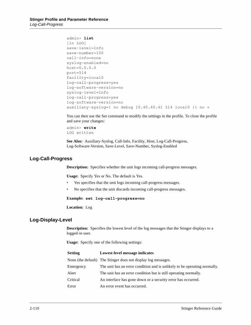
Stinger Profile and Parameter ReferenceLog-Call-Progress
lly.
admin> list[in LOG]save-level=infosave-number=100call-info=nonesyslog-enabled=nohost=0.0.0.0port=514facility=local0log-call-progress=yeslog-software-version=nosyslog-level=infolog-call-progress=yeslog-software-version=noauxiliary-syslog={ no debug 10.40.40.41 514 local0 }{ no +
You can then use the Set command to modify the settings in the profile. To close the profile and save your changes:
admin> writeLOG written
See Also: Auxiliary-Syslog, Call-Info, Facility, Host, Log-Call-Progress, Log-Software-Version, Save-Level, Save-Number, Syslog-Enabled
Log-Call-Progress
Description: Specifies whether the unit logs incoming call-progress messages.
Usage: Specify Yes or No. The default is Yes.
• Yes specifies that the unit logs incoming call-progress messages.
• No specifies that the unit discards incoming call-progress messages.
Example: set log-call-progress=no
Location: Log
Log-Display-Level
Description: Specifies the lowest level of the log messages that the Stinger displays to alogged-in user.
Usage: Specify one of the following settings:
Setting Lowest-level message indicates
None (the default) The Stinger does not display log messages.
Emergency The unit has an error condition and is unlikely to be operating norma
Alert The unit has an error condition but is still operating normally.
Critical An interface has gone down or a security error has occurred.
Error An error event has occurred.
2-110 Stinger Reference Guide
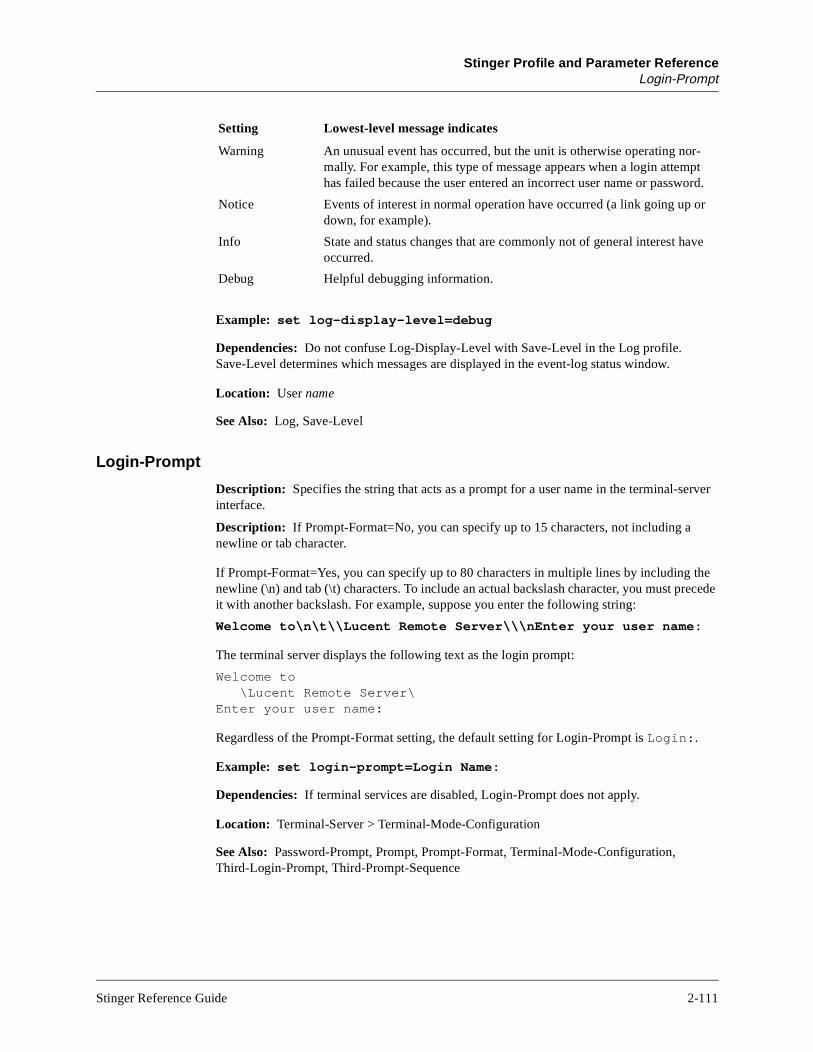
Stinger Profile and Parameter ReferenceLogin-Prompt
Example: set log-display-level=debug
Dependencies: Do not confuse Log-Display-Level with Save-Level in the Log profile. Save-Level determines which messages are displayed in the event-log status window.
Location: User name
See Also: Log, Save-Level
Login-Prompt
Description: Specifies the string that acts as a prompt for a user name in the terminal-server interface.
Description: If Prompt-Format=No, you can specify up to 15 characters, not including a newline or tab character.
If Prompt-Format=Yes, you can specify up to 80 characters in multiple lines by including the newline (\n) and tab (\t) characters. To include an actual backslash character, you must precede it with another backslash. For example, suppose you enter the following string:
Welcome to\n\t\\Lucent Remote Server\\\nEnter your user name:
The terminal server displays the following text as the login prompt:
Welcome to\Lucent Remote Server\
Enter your user name:
Regardless of the Prompt-Format setting, the default setting for Login-Prompt is Login:.
Example: set login-prompt=Login Name:
Dependencies: If terminal services are disabled, Login-Prompt does not apply.
Location: Terminal-Server > Terminal-Mode-Configuration
See Also: Password-Prompt, Prompt, Prompt-Format, Terminal-Mode-Configuration, Third-Login-Prompt, Third-Prompt-Sequence
Warning An unusual event has occurred, but the unit is otherwise operating nor-mally. For example, this type of message appears when a login attempt has failed because the user entered an incorrect user name or password.
Notice Events of interest in normal operation have occurred (a link going up or down, for example).
Info State and status changes that are commonly not of general interest have occurred.
Debug Helpful debugging information.
Setting Lowest-level message indicates
Stinger Reference Guide 2-111

Stinger Profile and Parameter ReferenceLogin-Timeout
es
the
Login-Timeout
Description: Specifies the number of seconds a user can wait to log into the terminal server. When a user attempts to log into the terminal server in terminal mode, a login prompt appears. If the user does not proceed any further than the login prompt within the number of seconds you specify, the login times out.
Usage: Specify a number of seconds from 0 to 300. The default is 300. If you set Login-Timeout to 0 (zero), the login never times out.
Example: set terminal-mode-configuration login-timeout=60
Location: Terminal-Server > Terminal-Mode-Configuration
See Also: Password-Prompt, Prompt, Prompt-Format, Terminal-Mode-Configuration, Third-Login-Prompt, Third-Prompt-Sequence
Log-Software-Version
Description: Specifies whether the unit logs the system version number.
Usage: Specify Yes of No. The default is No.
Example: set log-software-version=yes
Location: Log
Loopback
Description: Specifies whether to run a loopback test on the interface. While the interface is looped back, normal data traffic is interrupted.
Usage: Specify one of the following settings:
• No-Loopback (the default). The interface is operating normally.
• Facility-Loopback. During a facility loopback, the interface returns the signal it receivon the line.
• Local-Loopback. During a local loopback, the interface’s receive path is connected tointerface’s transmit path. The transmitted signal is still sent to the network as well.
Location: DS3-ATM {shelf-N trunk-module-N N} > Line-Config, OC3-ATM {shelf-N trunk-module-N N} > Line-Config
See Also: Loop-Timing
2-112 Stinger Reference Guide

Stinger Profile and Parameter ReferenceLoop-Timing
ck
Loop-Timing
Description: Enables or disables deriving transmission timing from receiver inputs.
Usage: Specify Yes or No. The default is Yes.
• Yes specifies that loop timing is enabled.
• No specifies that loop timing is disabled.
Example: set loop-timing=no
Location: OC3-ATM {shelf-N trunk-module-N N} > Line-Config
See Also: Loopback
Loss-Of-Cell-Delineation
Description: Indicates whether an HEC check failed on the line.
Usage: The Loss-Of-Cell-Delineation setting is read only. True indicates that an HEC chefailed. False indicates that the line passed an HEC check.
Example: loss-of-cell-delineation=false
Location: OC3-ATM-Stat {shelf-N trunk-module-N N}
See Also: Loss-Of-Signal
Loss-Of-Frame
Description: Indicates whether a framing error has occurred on the line (also known as ared alarm).
Usage: The Loss-Of-Frame value is read only. True indicates that a framing error has occurred on the line. False indicates that the line is up and in frame.
Example: loss-of-frame=false
Location: DS3-ATM {shelf-N slot-N N}, OC3-ATM-Stat {shelf-N trunk-module-N N}
See Also: Loss-Of-Signal
Loss-Of-Signal
Description: Indicates whether the carrier is maintaining a connection.
Usage: The Loss-Of-Signal value is read only. True indicates that the carrier is not maintaining a connection. False indicates that the carrier is maintaining a connection.
Example: loss-of-signal=false
Location: DS3-ATM {shelf-N slot-N N}, OC3-ATM-Stat {shelf-N trunk-module-N N}
See Also: Loss-Of-Frame
Stinger Reference Guide 2-113

Stinger Profile and Parameter ReferenceM
M
MAC-Address
Description: Specifies the Media Access Control (MAC) address of an Ethernet interface. An Ethernet MAC address is a 12-digit hexadecimal number denoting the physical address encoded in the controller.
Usage: In most cases, the MAC-Address value is obtained from the system. However, you can clone a profile by reading an existing one and changing its physical address.
Example: set mac-address=00:c0:6c:4e:ac:5a
Location: Ether-Info {shelf-N slot-N N}
See Also: Interface-Address, Link-State
Magic-Key
Description: Indicates the magic key for the Virtual Channel Connection (VCC).
Usage: The Magic-Key value is read only.
Location: ATMVCC-Stat circuit-name
See Also: Magic-Keys
Magic-Keys
Description: An array that contains read-only values for the Asynchronous Transfer Mode (ATM) magic keys.
Usage: With an ATMPVC-Stat profile as the working profile, enter list magic-keys to display the Magic-Keys values. For example:
admin> list magic-keys[in ATMPVC-STAT/unit1:magic-keys]magic-keys[1]=16777313magic-keys[2]=16777313
To return to a higher context in the profile:
admin> list ..
Location: ATMPVC-Stat circuit-name
See Also: Magic-Key
2-114 Stinger Reference Guide

Stinger Profile and Parameter ReferenceMajor-Firmware-Ver
d is is
d on
Major-Firmware-Ver
Description: Indicates the major firmware version of the SDSL Line Interface Module (LIM).
Usage: The Major-Firmware-Ver setting is read only.
Location: SDSL-Stat {shelf-N slot-N N} > Physical-Status
See Also: Dev-Line-State, Down-Stream-Rate, Hardware-Ver, IF-Group-Index, Minor-Firmware-Ver, Physical-Address, Unit-Type, Up-Stream-Rate
Management-Only-Interface
Description: Enables or disables management-only on the IP interface. The management-only interface can be the shelf-controller port or a port on an installed Ethernet card.
Usage: Specify Yes or No. The default is No.
• Yes specifies that incoming traffic on the interface terminates in the system itself, annot forwarded on any other interface. In addition, only traffic generated by the systemforwarded on the management-only interface. Traffic generated externally is droppethe interface.
• No specifies that the management-only feature is disabled.
Example: set management-only-interface=yes
Location: IP-Interface {shelf-N slot-N N}
See Also: Directed-Broadcast-Allowed, Interface-Address, IP-Address, Proxy-Mode, RIP-Mode
Manually-Spared-Slot-Number
Description: Specifies the primary Line Interface Module (LIM) associated with the sparespecified by Spare-Slot-Number.
Usage: Specify an integer. The default is any-slot.
Example: set manually-spared-slot-number=2
Dependencies: Manually-Spared-Slot-Number does not apply if Sparing-Mode=Inactive.
Location: LIM-Sparing-Config
See Also: Spare-Slot-Number, Sparing-Mode
Stinger Reference Guide 2-115
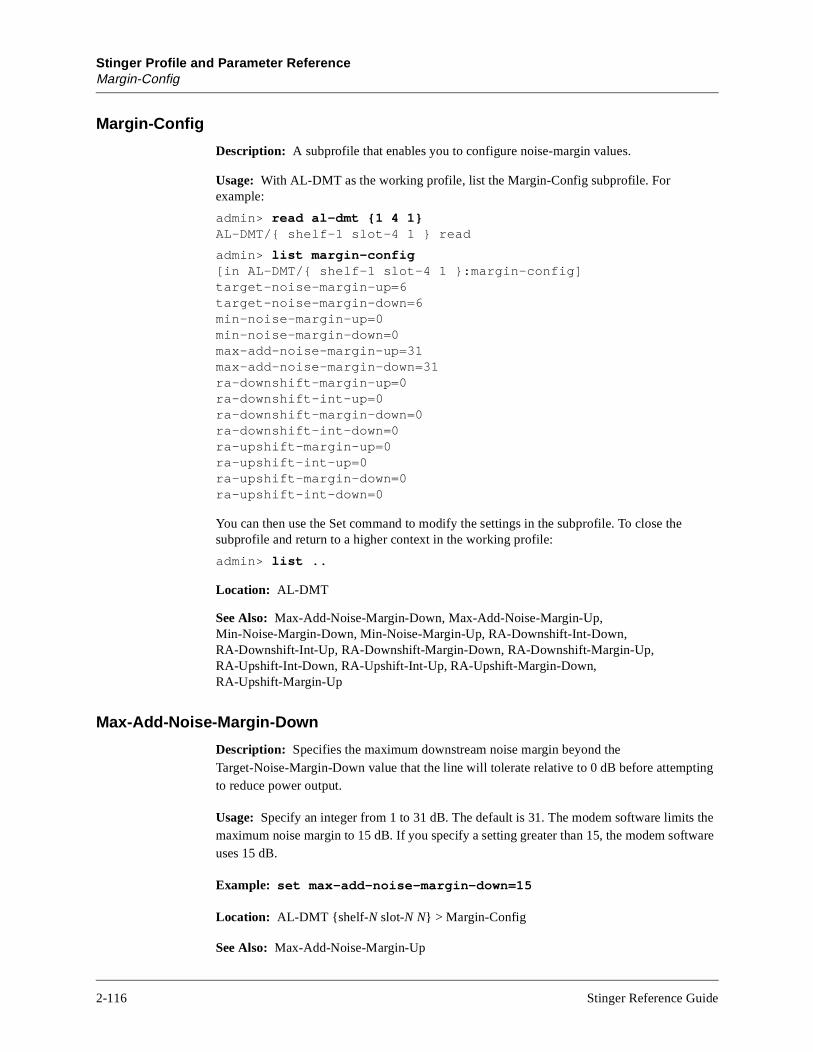
Stinger Profile and Parameter ReferenceMargin-Config
Margin-Config
Description: A subprofile that enables you to configure noise-margin values.
Usage: With AL-DMT as the working profile, list the Margin-Config subprofile. For example:
admin> read al-dmt {1 4 1}AL-DMT/{ shelf-1 slot-4 1 } read
admin> list margin-config[in AL-DMT/{ shelf-1 slot-4 1 }:margin-config]target-noise-margin-up=6target-noise-margin-down=6min-noise-margin-up=0min-noise-margin-down=0max-add-noise-margin-up=31max-add-noise-margin-down=31ra-downshift-margin-up=0ra-downshift-int-up=0ra-downshift-margin-down=0ra-downshift-int-down=0ra-upshift-margin-up=0ra-upshift-int-up=0ra-upshift-margin-down=0ra-upshift-int-down=0
You can then use the Set command to modify the settings in the subprofile. To close the subprofile and return to a higher context in the working profile:
admin> list ..
Location: AL-DMT
See Also: Max-Add-Noise-Margin-Down, Max-Add-Noise-Margin-Up, Min-Noise-Margin-Down, Min-Noise-Margin-Up, RA-Downshift-Int-Down, RA-Downshift-Int-Up, RA-Downshift-Margin-Down, RA-Downshift-Margin-Up, RA-Upshift-Int-Down, RA-Upshift-Int-Up, RA-Upshift-Margin-Down, RA-Upshift-Margin-Up
Max-Add-Noise-Margin-Down
Description: Specifies the maximum downstream noise margin beyond the Target-Noise-Margin-Down value that the line will tolerate relative to 0 dB before attempting to reduce power output.
Usage: Specify an integer from 1 to 31 dB. The default is 31. The modem software limits the maximum noise margin to 15 dB. If you specify a setting greater than 15, the modem software uses 15 dB.
Example: set max-add-noise-margin-down=15
Location: AL-DMT {shelf-N slot-N N} > Margin-Config
See Also: Max-Add-Noise-Margin-Up
2-116 Stinger Reference Guide

Stinger Profile and Parameter ReferenceMax-Add-Noise-Margin-Up
Max-Add-Noise-Margin-Up
Description: Specifies the maximum upstream noise margin beyond the Target-Noise-Margin-Up value that the line will tolerate relative to 0 dB before attempting to reduce power output.
Usage: Specify an integer from 1 to 31 dB. The default is 31. The modem software limits the maximum noise margin to 15 dB. If you specify a setting greater than 15, the modem software uses 15 dB.
Example: set max-add-noise-margin-up=15
Location: AL-DMT {shelf-N slot-N N} > Margin-Config
See Also: Max-Add-Noise-Margin-Down
Max-Aggr-Power-Level-Down
Description: Specifies the maximum aggregate power level on the downstream channel.
Usage: Specify an integer from 0 to 20 dBm. The default is 20.
Example: set max-aggr-power-level-down=13
Location: AL-DMT {shelf-N slot-N N} > Line-Config
See Also: Max-Aggr-Power-Level-Up
Max-Aggr-Power-Level-Up
Description: Specifies the maximum aggregate power level on the upstream channel.
Usage: Specify an integer from 0 to 13 dBm. The default is 13.
Example: set max-aggr-power-level-up=10
Location: AL-DMT {shelf-N slot-N N} > Line-Config
See Also: Max-Aggr-Power-Level-Down
Max-Bitrate-Down
Description: Specifies the maximum bit rate for downstream traffic.
Usage: Specify an integer from 0 to 15000 kbps. The default is 8000.
Example: set max-bitrate-down=10000
Dependencies: Consider the following:
• Max-Bitrate-Down does not apply to operator-controlled rate-adaptation.
• If you set Max-Bitrate-Down to a nonzero value in the one subprofile, set Max-Bitrate-Down to 0 (zero) in the other subprofile.
Stinger Reference Guide 2-117

Stinger Profile and Parameter ReferenceMax-Bitrate-Up
0
inute, lt is 0 call.
Location: AL-DMT {shelf-N slot-N N} > Fast-Path-Config,AL-DMT {shelf-N slot-N N} > Interleave-Path-Config
See Also: Max-Bitrate-Up
Max-Bitrate-Up
Description: Specifies the maximum bit rate for upstream traffic.
Usage: Specify an integer from 0 to 2000 kbps. The default is 1000.
Example: set max-bitrate-up=1200
Dependencies: Consider the following:
• Max-Bitrate-Up does not apply to operator-controlled rate-adaptation.
• If you set Max-Bitrate-Up to a nonzero value in one subprofile, set Max-Bitrate-Up to(zero) in the other subprofile.
Location: AL-DMT {shelf-N slot-N N} > Fast-Path-Config,AL-DMT {shelf-N slot-N N} > Interleave-Path-Config
See Also: Max-Bitrate-Down
Max-Call-Duration
Description: Specifies the maximum number of minutes an incoming call can remain connected. For a multichannel call, the maximum applies to each channel.
Usage: Specify a number from 0 to 1440. The Stinger checks the connection once per mso the actual time the call is connected is slightly longer than the time you set. The defau(zero), which specifies that the Stinger does not set a limit on the duration of an incoming
Location: Answer-Defaults > Session-Info, Connection station > Session-Options
See Also: Session-Options
Max-Delay-Down
Description: Specifies the maximum allowed downstream delay induced by interleaving data.
Usage: Specify a value from 0 to 255 in microseconds. The default is 16.
Example: set max-delay-down=10
Location: AL-DMT {shelf-N slot-N N} > Interleave-Path-Config
See Also: Max-Delay-Up
2-118 Stinger Reference Guide
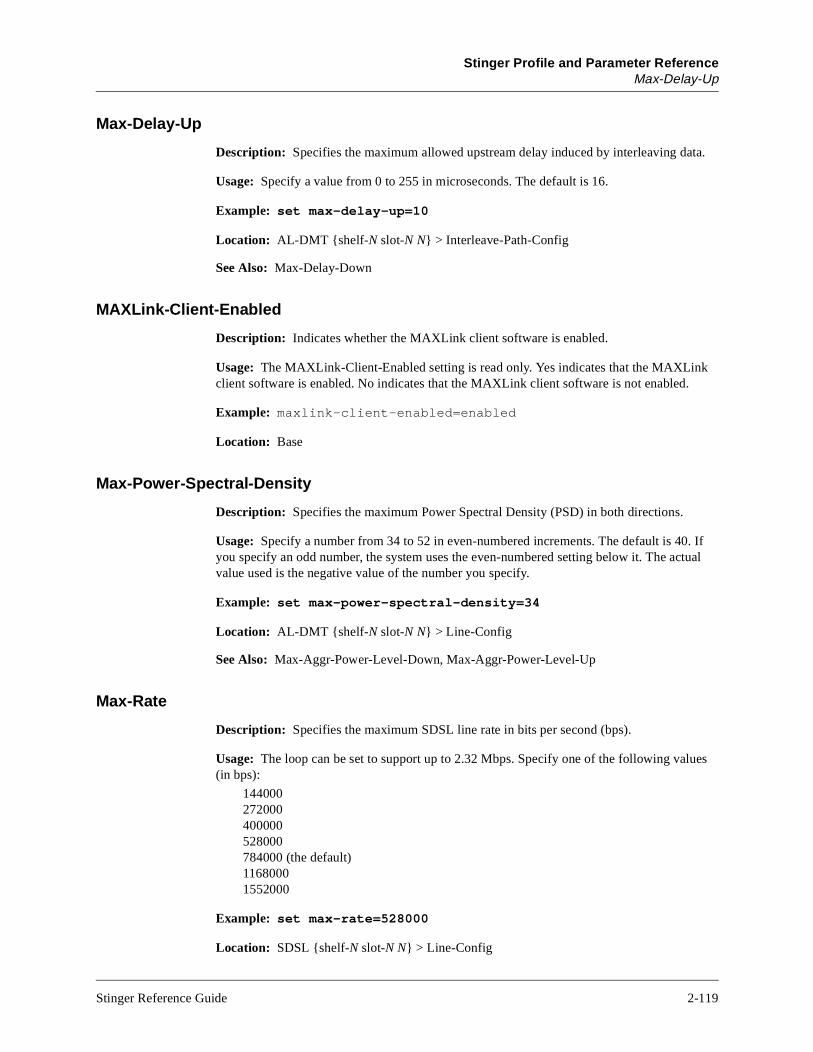
Stinger Profile and Parameter ReferenceMax-Delay-Up
Max-Delay-Up
Description: Specifies the maximum allowed upstream delay induced by interleaving data.
Usage: Specify a value from 0 to 255 in microseconds. The default is 16.
Example: set max-delay-up=10
Location: AL-DMT {shelf-N slot-N N} > Interleave-Path-Config
See Also: Max-Delay-Down
MAXLink-Client-Enabled
Description: Indicates whether the MAXLink client software is enabled.
Usage: The MAXLink-Client-Enabled setting is read only. Yes indicates that the MAXLink client software is enabled. No indicates that the MAXLink client software is not enabled.
Example: maxlink-client-enabled=enabled
Location: Base
Max-Power-Spectral-Density
Description: Specifies the maximum Power Spectral Density (PSD) in both directions.
Usage: Specify a number from 34 to 52 in even-numbered increments. The default is 40. If you specify an odd number, the system uses the even-numbered setting below it. The actual value used is the negative value of the number you specify.
Example: set max-power-spectral-density=34
Location: AL-DMT {shelf-N slot-N N} > Line-Config
See Also: Max-Aggr-Power-Level-Down, Max-Aggr-Power-Level-Up
Max-Rate
Description: Specifies the maximum SDSL line rate in bits per second (bps).
Usage: The loop can be set to support up to 2.32 Mbps. Specify one of the following values (in bps):
144000 272000 400000 528000 784000 (the default) 1168000 1552000
Example: set max-rate=528000
Location: SDSL {shelf-N slot-N N} > Line-Config
Stinger Reference Guide 2-119

Stinger Profile and Parameter ReferenceMax-Source-Port
See Also: Data-Rate-Mode
Max-Source-Port
Description: Specifies the highest Rlogin source port value.
Usage: Specify an integer from 128 to 1023. The default is 1023. The value you specify should be greater than or equal to the setting of Min-Source-Port.
Example: set max-source-port=250
Dependencies: Rlogin must be enabled for Max-Source-Port to have any effect.
Location: Terminal-Server > Terminal-Mode-Configuration > Rlogin-Options
See Also: Min-Source-Port
Max-Upstream-Bandwidth
Description: Indicates the maximum upstream bandwidth of all Line Interface Modules (LIMs).
Usage: The Max-Upstream-Bandwidth value is read only.
Example: max-upstream-bandwidth=622160
Location: Bandwidth-Stats
See Also: Active-Upstream-Bandwidth-On-Trunks, Standby-Upstream-Bandwidth-On-Trunks
Menu-Mode-Options
Description: A subprofile containing terminal-server configuration options for menu mode.
Usage: With Terminal-Server as the working profile, list the Menu-Mode-Options subprofile. For example:
admin> list menu-mode-options
[in TERMINAL-SERVER:menu-mode-options]
start-with-menus=no
toggle-screen=no
remote-configuration=no
text-1=""
host-1=0.0.0.0
text-2=""
host-2=0.0.0.0
text-3=""
host-3=0.0.0.0
text-4=""
host-4=0.0.0.0
2-120 Stinger Reference Guide

Stinger Profile and Parameter ReferenceMetric
kely
rate
n
You can then use the Set command to modify the settings in the subprofile. To close the subprofile and return to a higher context in the working profile:
admin> list ..
Location: Terminal-Server
See Also: Host-N (N=1–4), Remote-Configuration, Start-With-Menus, Text-N (N=1–4), Toggle-Screen
Metric
Description: Specifies a RIP-style metric for the route.
Usage: Specify an integer from 1 to 15. The default is 1. The higher the metric, the less lithat the Stinger uses the route.
Example: set metric=8
Location: IP-Route name
See Also: RIP, RIP-Mode, Routing-Metric
Min-Bitrate-Down
Description: Specifies the minimum bit rate for downstream traffic.
Usage: Specify an integer from 0 to 15000 kbps. The default is 50.
Example: set min-bitrate-down=100
Dependencies: Consider the following:
• When automatic rate-adaptive mode is in effect, the line initializes at the downstreamof Min-Bitrate-Down, or it does not initialize at all.
• Min-Bitrate-Down does not apply to operator-controlled rate-adaptation.
• If you set Min-Bitrate-Down to a nonzero value in one subprofile, set Min-Bitrate-Dowto 0 (zero) in the other subprofile.
Location: AL-DMT {shelf-N slot-N N} > Fast-Path-Config,AL-DMT {shelf-N slot-N N} > Interleave-Path-Config
See Also: Min-Bitrate-Up
Stinger Reference Guide 2-121

Stinger Profile and Parameter ReferenceMin-Bitrate-Up
te of
mits
tive
mits
Min-Bitrate-Up
Description: Specifies the minimum bit rate for upstream traffic.
Usage: Specify an integer from 0 to 2000 kbps. The default is 10.
Example: set min-bitrate-up=20
Dependencies: Consider the following:
• When automatic rate-adaptive mode is in effect, the line initializes at the upstream raMin-Bitrate-Up, or it does not initialize at all.
• Min-Bitrate-Up does not apply to operator-controlled rate-adaptation.
• If you set Min-Bitrate-Up to a nonzero value in one subprofile, set Min-Bitrate-Up to 0(zero) in the other subprofile.
Location: AL-DMT {shelf-N slot-N N} > Fast-Path-Config, AL-DMT {shelf-N slot-N N} > Interleave-Path-Config
See Also: Min-Bitrate-Down
Min-Noise-Margin-Down
Description: Specifies the minimum downstream noise margin that the line will tolerate relative to 0 dB before attempting to increase power output.
Usage: Specify an integer from 1 to 31 dB. The default is 0 (zero). The modem software lithe maximum noise margin to 15 dB. If you specify a setting greater than 15, the modemsoftware uses 15 dB.
Example: set min-noise-margin-down=15
Location: AL-DMT {shelf-N slot-N N} > Margin-Config
See Also: Min-Noise-Margin-Up
Min-Noise-Margin-Up
Description: Specifies the minimum upstream noise margin that the line will tolerate relato 0 dB before attempting to increase power output.
Usage: Specify an integer from 1 to 31 dB. The default is 0 (zero). The modem software lithe maximum noise margin to 15 dB. If you specify a setting greater than 15, the modemsoftware uses 15 dB.
Example: set min-noise-margin-up=15
Location: AL-DMT {shelf-N slot-N N} > Margin-Config
See Also: Min-Noise-Margin-Down
2-122 Stinger Reference Guide
Stinger Profile and Parameter ReferenceMinor-Firmware-Ver
Minor-Firmware-Ver
Description: Indicates the minor firmware version of the SDSL Line Interface Module (LIM).
Usage: The Minor-Firmware-Ver setting is read only.
Location: SDSL-Stat {shelf-N slot-N N} > Physical-Status
See Also: Dev-Line-State, Down-Stream-Rate, Hardware-Ver, IF-Group-Index, Major-Firmware-Ver, Physical-Address, Unit-Type, Up-Stream-Rate
Min-Source-Port
Description: Specifies the lowest Rlogin source port value.
Usage: Specify an integer from 128 to 1023. The default is 1023. The value you specify should be less than or equal to the setting of Max-Source-Port.
Example: set min-source-port=250
Dependencies: Rlogin must be enabled for Min-Source-Port to have any effect.
Location: Terminal-Server > Terminal-Mode-Configuration > Rlogin-Options
See Also: Max-Source-Port
Modem-Hw-State
Description: Indicates the state of the interface after initialization.
Usage: The Modem-Hw-State value is read only. The init-ok value indicates that the the interface is functioning normally. The other three possible values—bad-sdram, bad-cache, and bad-cache-sdram—indicate memory problems, probably associatedwith a self-test failure.
Example: modem-hw-state=init-ok
Location: AL-DMT-Stat {shelf-N slot-N N} > Physical-Status
See Also: Hardware-Ver
Multi-Rate-Enabled
Description: Indicates whether the unit can make DWS calls.
Usage: The Multi-Rate-Enabled setting is read only. Yes indicates that the unit can makeDWS calls. No indicates that the unit cannot make DWS calls.
Example: multi-rate-enabled=yes
Location: Base
See Also: R2-Signaling-Enabled, Switched-Enabled
Stinger Reference Guide 2-123

Stinger Profile and Parameter ReferenceMust-Agree
Must-Agree
Description: Specifies whether the controllers must agree on the choice of a primary Control Module (CM).
Usage: Specify True or False. The default is False, which enables a CM to become primary without the agreement of the other CM. The default setting is recommended.
Example: set must-agree=False
Location: Redundancy > Context > Context N
See Also: Primary-Preference
2-124 Stinger Reference Guide

Stinger Profile and Parameter ReferenceN
uses
s
N
Nailed-Group
Description: Specifies a nailed group number associated with a physical line, channel, or interface.
Usage: Specify an integer from 0 to 1024. The default is 0 (zero). In the ATM-Options subprofile, the Nailed-Group value specifies the nailed group number associated with the physical interface used by the first side of the circuit. In the ATM-Connect-Options subprofile, the Nailed-Group value specifies the nailed group number associated with the physical interface used by the second side of the circuit.
Example: set nailed-group=7
Dependencies: Consider the following:
• Do not associate a group number with more than one active profile.
• Referring to the group number in the Nailed-Groups setting of a Connection profile cathe connection to use the associated physical interface.
• The Nailed-Group value in the ATM-Options subprofile must match the Nailed-Groupvalue in the Telco-Options subprofile.
Location: AL-DMT {shelf-N slot-N N} > Line ConfigConnection > ATM-Options, Connection > ATM-Connect-Options, DS3-ATM {shelf-N slot-N N} > Line-Config, OC3-ATM {shelf-N trunk-module-N N} > Line-Config, SDSL {shelf-N slot-N N} > Line-Config
See Also: Line-Config, Nailed-Groups
Nailed-Groups
Description: Specifies a nailed-up group belonging to a session.
Usage: Specify a number assigned to a group.
Example: set nailed-groups=1
Location: Connection station > Telco-Options
See Also: Nailed-Group, Telco-Options
Stinger Reference Guide 2-125

Stinger Profile and Parameter ReferenceName
4
ult
ve.
y
Name
Description: Assigns a name to a profile, user, route, host, slot card, or the Stinger system itself.
Usage: Specify a descriptive name with no embedded spaces.
• For all profiles except the IP-Route, SDSL, and Trap profiles, you can specify up to 2characters.
• For the IP-Route and Trap profiles, you can specify up to 31 characters.
• For the AL-DMT, OC3-ATM, and SDSL profiles, you can specify up to 16 characters.
• The default is null in all except User and OC3-ATM profiles. In a User profile, the defais default. In an OC3-ATM profile, the default is the interface address in shelf:slot:item format.
Example: set name=newyork
Dependencies: If the Stinger uses the specified value for authentication, it is case sensiti
Location: Alarm name, AL-DMT {shelf-N slot-N N}, IP-Route name, OC3-ATM {shelf-N trunk-module-N N}, SDSL {shelf-N slot-N N}, System, Trap host-name, User name
See Also: AL-DMT, DS3-ATM (profile), IP-Route, Physical-Address, SDSL (profile), System, Trap, User
Near-End-CRC
Description: Indicates the number of Cyclic Redundancy Check (CRC) errors detected bCOE’s ADSL Transceiver Unit (ATU).
Usage: The Near-End-CRC value is read only.
Example: near-end-crc=0
Location: AL-DMT-Stat {shelf-N slot-N N} > Physical-Statistic
See Also: Near-End-FEC, Near-End-HEC
Near-End-FEC
Description: Indicates the number of Forward Error Correction (FEC) errors detected byCOE’s ADSL Transceiver Unit (ATU).
Usage: The Near-End-FEC value is read only.
Example: near-end-fec=0
Location: AL-DMT-Stat {shelf-N slot-N N} > Physical-Statistic
See Also: Near-End-CRC, Near-End-HEC
2-126 Stinger Reference Guide

Stinger Profile and Parameter ReferenceNear-End-HEC
ion is
ive
ved,
s
Near-End-HEC
Description: Indicates the number of Header Error Checksum (HEC) errors detected by COE’s ADSL Transceiver Unit (ATU).
Usage: The Near-End-HEC value is read only.
Example: near-end-hec=0
Location: AL-DMT-Stat {shelf-N slot-N N} > Physical-Statistic
See Also: Near-End-CRC, Near-End-FEC
Network-Management-Enabled
Description: Indicates whether the network-management option is enabled.
Usage: The Network-Management-Enabled option is read only. Yes indicates that the network-management option is enabled. No indicates that the network-management optdisabled.
Example: network-management-enabled=yes
Location: Base
See Also: AIM-Enabled
NoAttr6-Use-Termsrv
Description: Specifies whether the unit initiates a terminal-server login if it does not receRADIUS attribute 6 (User-Service).
Usage: Specify Yes or No. The default is Yes.
• Yes specifies that the Stinger initiates a terminal-server login if Attribute 6 is not receiregardless of whether Attribute 7 is received or not.
• No specifies that:
– If Attribute 6 is not received, but Attribute 7 is received, a framed-protocol login iinitiated.
– If neither Attribute 6 nor 7 is received, a terminal-server login is initiated.
Example: The following example instructs the Stinger to start a framed-protocol login if Attribute 7 is received without Attribute 6:
admin> read external-authEXTERNAL-AUTH read
admin> set noattr6-use-termsrv=no
admin> writeEXTERNAL-AUTH written
Location: External-Auth
See Also: Acct-Type, Auth-Type, Local-Profiles-First, Rad-Acct-Client, Rad-Auth-Client, Rad-ID-Source-Unique, Rad-ID-Space
Stinger Reference Guide 2-127
Stinger Profile and Parameter ReferenceNoise-Margin-Down
Noise-Margin-Down
Description: Indicates the current downstream noise margin in dB.
Usage: The Noise-Margin-Down value is read only.
Example: noise-margin-down=6
Location: AL-DMT-Stat {shelf-N slot-N N} > Physical-Statistic
See Also: Noise-Margin-Up
Noise-Margin-Up
Description: Indicates the current upstream noise margin in dB.
Usage: The Noise-Margin-Up value is read only.
Example: noise-margin-up=6
Location: AL-DMT-Stat {shelf-N slot-N N} > Physical-Statistic
See Also: Noise-Margin-Down
Num-Sec-Invalid
Description: Specifies how many error seconds were detected during the continuous Bit Error-Rate Test (BERT).
Usage: The Num-Sec-Invalid value is read only.
Location: AL-DMT-Stat {shelf-N slot-N N} > Physical-Status
See Also: Num-Sec-Valid
Num-Sec-Valid
Description: Specifies how many seconds were error-free during the continuous Bit Error-Rate Test (BERT).
Usage: The Num-Sec-Valid value is read only.
Location: AL-DMT-Stat {shelf-N slot-N N} > Physical-Status
See Also: Num-Sec-Invalid
2-128 Stinger Reference Guide
Stinger Profile and Parameter ReferenceO
O
OC3-ATM
Description: A profile containing configuration settings for the OC3-ATM interface.
Usage: Use the Read and List commands to make OC3-ATM the working profile:
admin> read oc3-atm/{ shelf-1 trunk-module-2 1 }]OC3-ATM read
admin> list[in OC3-ATM/{ shelf-1 trunk-module-2 1 }]
name=1:18:1physical-address*={ shelf-1 trunk-module-2 1 }enabled=nospare-physical-address={ any-shelf any-slot 0 }sparing-enabled=yesline-config={ 0 0 { any-shelf any-slot 0 } no-loopback STS-3c +
You can then use the Set command to modify the settings in the profile. To close the profile and save your changes:
admin> writeOC3-ATM written
See Also: Enabled, Line-Config, Name, Physical-Address
OC3-ATM-Stat
Description: A profile that provides ATM framer status and error counters for an OC3 interface.
Usage: Use the Read and List commands to make OC3-ATM the working profile:
admin> read oc3-atm/{ shelf-1 trunk-module-2 1 }]OC3-ATM read
admin> list[in OC3-ATM-STAT/{ shelf-1 trunk-module-2 1 }]physical-address*={ shelf-1 trunk-module-2 1 }line-state=activespare-physical-address={ any-shelf any-slot 0 }sparing-state=sparing-noneloss-of-signal=Falseloss-of-frame=Falseout-of-frame=Falsesection-state=sonet-section-active-no-defectpath-state=sonet-path-active-no-defectais-receive=Falseyellow-receive=Falseout-of-cell-delineation=Falseloss-of-cell-delineation=Falseaps-receive=Falsersop-bip-error-count=0
Stinger Reference Guide 2-129

Stinger Profile and Parameter ReferenceOperational-Count
rlop-bip-error-count=0rlop-febe-error-count=0rpop-bip-error-count=0rpop-febe-error-count=0racp-chcs-error-count=0racp-uchcs-error-count=12064racp-rx-cell-count=32855tacp-tx-cell-count=16frequency-justification-count=0HEC-cell-drop-counter=0FIFO-overflow-counter=0idle-cell-counter=0valid-cell-counter=0performance-monitoring={0 0 0 0 0 0 0 0 0 0 0 0 0 0 0 0 0 0 0 0}interval-performance-monitoring=[ { 0 0 0 0 0 0 0 0 0 0 0 0 0 0+
See Also: AIS-Receive, FIFO-Overflow-Counter, Frequency-Justification-Count, HEC-Cell-Drop-Counter, Idle-Cell-Counter, Interval-Performance-Monitoring, Line-State, Loss-Of-Cell-Delineation, Loss-Of-Frame, Loss-Of-Signal, Out-Of-Cell-Delineation, Out-Of-Frame, Path-State, Performance-Monitoring, Physical-Address, RACP-CHCS-Error-Count, RACP-RX-Cell-Count, RACP-UCHCS-Error-Count, RLOP-BIP-Error-Count, RLOP-FEBE-Error-Count, RPOP-BIP-Error-Count, RPOP-FEBE-Error-Count, RSOP-BIP-Error-Count, Section-State, Spare-Physical-Address, Sparing-State, TACP-TX-Cell-Count, Valid-Cell-Counter, Yellow-Receive
Operational-Count
Description: Indicates the number of devices that are in the up state.
Usage: The Operational-Count setting is read only.
Example: operational-count=10
Location: Device-Summary
See Also: Device-ID, Disabled-Count, Total-Count
Out-Of-Cell-Delineation
Description: Indicates whether the device is receiving a far-end loss-of-frame signal, also known as a Yellow Alarm.
Usage: The Out-Of-Cell-Delineation value is read only. True indicates that the device is receiving a far-end loss-of-frame signal. False indicates that the device is not receiving a far-end loss-of-frame signal.
Example: out-of-cell-delineation=false
Location: OC3-ATM-Stat {shelf-N trunk-module-N N}
See Also: Out-Of-Frame
2-130 Stinger Reference Guide
Stinger Profile and Parameter ReferenceOut-Of-Frame
Out-Of-Frame
Description: Indicates whether the local line is up and in frame.
Usage: The Out-Of-Frame value is read only. True indicates that the line is down and out of frame. False indicates that the line is up and in frame.
Example: out-of-frame=false
Location: OC3-ATM-Stat {shelf-N trunk-module-N N}
See Also: Loss-Of-Frame, Out-Of-Cell-Delineation
Output-Power-Down
Description: Indicates the current downstream aggregate power level in dB.
Usage: The Output-Power-Down value is read only.
Example: output-power-down=19
Location: AL-DMT-Stat {shelf-N slot-N N} > Physical-Statistic
See Also: Output-Power-Up
Output-Power-Up
Description: Indicates the current upstream aggregate power level in dB.
Usage: The Output-Power-Up value is read only.
Example: output-power-up=19
Location: AL-DMT-Stat {shelf-N slot-N N} > Physical-Statistic
See Also: Output-Power-Down
Stinger Reference Guide 2-131

Stinger Profile and Parameter ReferenceP
arded
rs
er is
P
Parallel-Dialing
Description: Specifies the number of call-setup requests the system sends to the network side at any given time.
Usage: Specify an integer from 1 to 64. If the Stinger has trouble establishing an initial connection at the full bandwidth for calls from the U.S. to another country, reduce Parallel-Dialing to a value of 1. For ADSL or SDSL operation, you must set Parallel-Dialing to the number of ADSL or SDSL interfaces. The default is 2.
Example: set parallel-dialing=12
Dependencies: If the system is processing the maximum number of calls when it receives a new call request, it queues the request and processes it after the network side sends a call-proceeding message for a previous request.
Location: System
See Also: Dial-Number
Partial-Packet-Discard
Description: Specifies whether the remaining cells in a packet (except the last cell) should be discarded if buffers become congested after some cells of a packet have been queued.
Usage: Specify Yes or No. The default is Yes.
• Yes specifies that the remaining cells in a packet (except the last cell) should be discif buffers become congested after some cells of a packet have been queued.
• No specifies that none of the remaining cells in a packet should be discarded if buffebecome congested after some cells of a packet have been queued.
Dependencies: If Encapsulation-Protocol is not set to ATM or ATM-Circuit, Partial-Packet-Discard does not apply.
Location: ATM-QoS
See Also: AAL-Type, Contract-Name, Early-Packet-Discard, QoS-Class
Password
Description: Specifies a password that the user must enter in order to log in.
Usage: Specify a text string of up to 20 characters. The default is null. The value you entcase sensitive.
Example: set password=mypw
Location: User name
See Also: Security-Mode, System-Password, Telnet-Password
2-132 Stinger Reference Guide

Stinger Profile and Parameter ReferencePassword-Enabled
for
word
Password-Enabled
Description: Specifies whether all failed Telnet login attempts generate a trap.
Usage: Specify Yes or No. The default is Yes.
• Yes specifies that all failed Telnet login attempts generate a trap.
• No specifies that all failed Telnet login attempts do not generate a trap.
Example: set password-enabled=no
Dependencies: When Password-Enabled=Yes, you must also set Security-Enabled=Yes all failed Telnet login attempts to generate a trap.
Location: Trap host-name
See Also: Security-Enabled
Password-Prompt
Description: Specifies the string the terminal server uses to prompt for the System-Passwhen authentication is in use and an interactive user initiates a connection.
Usage: Specify up to 15 characters. The default is Password:
Example: set password-prompt=Your Password:
Dependencies: If terminal services are disabled, Password-Prompt does not apply.
Location: Terminal-Server > Terminal-Mode-Configuration
See Also: Login-Prompt, Prompt, Prompt-Format, Terminal-Mode-Configuration, Third-Login-Prompt, Third-Prompt-Sequence
Path-State
Description: Indicates the state of the SONET path.
Usage: The Path-State value is read only.
Example: path-state=sonet-path-active-no-defect
Location: OC3-ATM-Stat {shelf-N trunk-module-N N}
See Also: Section-State
Stinger Reference Guide 2-133
Stinger Profile and Parameter ReferenceP-Bit-Error-Count
P-Bit-Error-Count
Description: Indicates the number of P-bit errors received since the last time the unit was reset. P-bit errors indicate that the unit received a P-bit code on the DS3 M-frame that differs from the locally calculated code.
Usage: The P-Bit-Error-Count value is read only.
Example: p-bit-error-count=0
Location: DS3-ATM-Stat {shelf-N slot-N N}
See Also: AIS-Receive, BPV-Error-Count, CP-Bit-Error-Count, F-Bit-Error-Count, FEB-Error-Count, Line-State, Loss-Of-Frame, Loss-Of-Signal, Physical-Address, Yellow-Receive
Performance-Monitoring
Description: A subprofile that provides cumulative SONET performance counters, which are reset at the end of every 15-minute interval.
Usage: With OC3-ATM-Stat as the working profile, list the Performance-Monitoring subprofile. For example:
admin> list
[in OC3-ATM-STAT/{ shelf-1 trunk-module-2 1 }:performance-monitoring]
sonet-section-errored-seconds=0
sonet-section-severely-errored-seconds=0
sonet-section-severely-errored-framing-seconds=0
sonet-section-coding-violations=0
sonet-line-errored-seconds=0
sonet-line-severely-errored-seconds=0
sonet-line-coding-violations=0
sonet-line-unavailable-seconds=0
sonet-far-end-line-errored-seconds=0
sonet-far-end-line-severely-errored-seconds=0
sonet-far-end-line-coding-violations=0
sonet-far-end-line-unavailable-seconds=0
sonet-path-errored-seconds=0
sonet-path-severely-errored-seconds=0
sonet-path-coding-violations=0
sonet-path-unavailable-seconds=0
sonet-far-end-path-errored-seconds=0
sonet-far-end-path-severely-errored-seconds=0
sonet-far-end-path-coding-violations=0
sonet-far-end-path-unavailable-seconds=0
You can then use the Set command to modify the settings in the subprofile. To close the subprofile and return to a higher context in the working profile:
admin> list ..
Location: OC3-ATM-Stat {shelf-N trunk-module-N N}
2-134 Stinger Reference Guide
Stinger Profile and Parameter ReferencePerm-Conn-Upd-Mode
g is .
. No
See Also: Interval-Performance-Monitoring, SONET-Far-End-Line-Coding-Violations, SONET-Far-End-Line-Errored-Seconds, SONET-Far-End-Line-Severely-Errored-Seconds, SONET-Far-End-Line-Unavailable-Seconds, SONET-Far-End-Path-Coding-Violations, SONET-Far-End-Path-Errored-Seconds, SONET-Far-End-Path-Severely-Errored-Seconds, SONET-Far-End-Path-Unavailable-Seconds, SONET-Line-Coding-Violations, SONET-Line-Errored-Seconds, SONET-Line-Severely-Errored-Seconds, SONET-Line-Unavailable-Seconds, SONET-Path-Coding-Violations, SONET-Path-Errored-Seconds, SONET-Path-Severely-Errored-Seconds, SONET-Path-Unavailable-Seconds, SONET-Section-Coding-Violations, SONET-Section-Errored-Seconds, SONET-Section-Severely-Errored-Framing-Seconds, SONET-Section-Severely-Errored-Seconds
Perm-Conn-Upd-Mode
Description: Specifies under what circumstances the Stinger performs nonintrusive remote updates of the configurations of permanent connections.
Usage: Specify one of the following values:
• All (the default) specifies that, if they are fetched from the RADIUS server, all existinpermanent connections will be torn down and reestablished following the update. Thsetting causes service interruption every time any nailed profile is updated or added
• Changed specifies that only changed permanent connections will be torn down and reestablished.
Example: set perm-conn-upd-mode=changed
Location: System
See Also: Analog-Encoding, Idle-Logout, Parallel-Dialing, SessionID-Base, Single-File-Incoming, System-Rmt-Mgmt,Use-Trunk-Groups
PHS-Support
Description: Indicates whether support for the Personal Handyphone System (PHS) is enabled.
Usage: The PHS-Support setting is read only. Yes indicates that PHS support is enabledindicates that PHS support is disabled.
Example: phs-support=yes
Location: Base
See Also: Countries-Enabled, MAXLink-Client-Enabled, Multi-Rate-Enabled, R2-Signaling-Enabled, Selectools-Enabled
Stinger Reference Guide 2-135
Stinger Profile and Parameter ReferencePhysical-Address
lots lf
for tire lf 1:
Physical-Address
Description: Identifies the physical address of an interface.
Usage: The physical address has the format {shelf slot item}, where:
In most cases, the value of Physical-Address is obtained from the system. However, you can clone a profile by reading an existing one and changing its physical address. Use the List and Set commands to modify the Physical-Address value. For example:
admin> list physical-address[in SDSL/{ shelf-1 slot-1 1 }:physical-address]shelf=shelf-1slot=slot-9item-number=37
admin> set shelf=shelf-2
As an alternative, you can just use the Set command. For example:
admin> set physical-address shelf=shelf-2
Location: Alarm name, AL-DMT {shelf-N slot-N N}, DS3-ATM {shelf-N slot-N N}, OC3-ATM {shelf-N trunk-module-N N}, OC3-ATM-Stat {shelf-N trunk-module-N N},SDSL {shelf-N slot-N N}, SDSL-Stat {shelf-N slot-N N}
See Also: Device-Address, Interface-Address, Item-Number, Shelf, Slot
Syntax element Description
shelf Specifies the shelf in which the item resides. If you are using a single-shelf system, the shelf number is always 1.
slot Specifies the number of the item’s expansion slot. Physical expansion sare numbered from 1 to 16, starting with 1 for the slot just below the shecontroller. The slot value 17, controller, or c specifies the shelf con-troller card. For example, to address the first slot on shelf 1:
{ 1 1 0 }
item Specifies an item on the slot card. Items are numbered starting with #1 the leftmost item on the card. An item number of 0 (zero) denotes the enslot. For example, to address line #48 on an SDSL card in slot #2 on she
{ 1 2 48 }
2-136 Stinger Reference Guide
Stinger Profile and Parameter ReferencePhysical-Statistic
Physical-Statistic
Description: A subprofile that reports statistics about the RADSL or SDSL interface.
Usage: With AL-DMT-Stat or SDSL-Stat as the working profile, list the Physical-Statistic subprofile. For example:
admin> list[in SDSL-STAT { shelf-1 slot-1 0 }:physical-statistic]line-up-timer={ 1 13 55 }rx-signal-present=yesline-quality=15up-dwn-cntr=0self-test=passedfar-end-db-attenuation=4firmware-startup-stage=normal-operationbert-timer=2 minutesbert-enable=nobert-operation-state=stoppedbert-error-counter=0
You can then use the Set command to modify the settings in the subprofile. To close the subprofile and return to a higher context in the working profile:
admin> list ..
Location: AL-DMT-Stat {shelf-N slot-N N}, SDSL-Stat {shelf-N slot-N N}
See Also: Physical-Status
Physical-Status
Description: A subprofile that indicates the status of the RADSL or SDSL interface.
Usage: With AL-DMT-Stat or SDSL-Stat as the working profile, list the Physical-Status subprofile. For example:
admin> list physical-status[in SDSL-STAT { shelf-1 slot-1 0 }:physical-status ]if-group-index=0unit-type=coedev-line-state=port-upup-stream-rate=784000down-stream-rate=784000major-firmware-ver=13minor-firmware-ver=2hardware-ver=2
You can then use the Set command to modify the settings in the subprofile. To close the subprofile and return to a higher context in the working profile:
admin> list ..
Location: AL-DMT-Stat {shelf-N slot-N N}, SDSL-Stat {shelf-N slot-N N}
See Also: Physical-Statistic
Stinger Reference Guide 2-137

Stinger Profile and Parameter ReferencePing
led
use
se on
e-Up
Ping
Description: Enables and disables the terminal-server Ping command.
Usage: Specify Yes or No. The default is No.
• Yes enables terminal-server users to use the Ping command.
• No disables the Ping command in the terminal-server interface.
Example: set ping=yes
Location: Terminal-Server > Terminal-Mode-Configuration
See Also: SLIP, TCP, Telnet, Terminal-Mode-Configuration, Traceroute
Planned-Bitrate-Down
Description: Specifies the constant bit rate for downstream traffic when operator-controlrate-adaptive mode is in effect.
Usage: Specify an integer from 0 to 15000 kbps. The default is 1000.
Example: set planned-bitrate-down=100
Dependencies: Consider the following:
• Planned-Bitrate-Down does not apply when automatic-at-startup rate adaptation is inon the line.
• If you set Planned-Bitrate-Down to a nonzero value in one subprofile, set Planned-Bitrate-Down to 0 (zero) in the other subprofile.
Location: AL-DMT {shelf-N slot-N N} > Fast-Path-Config,AL-DMT {shelf-N slot-N N} > Interleave-Path-Config
See Also: Planned-Bitrate-Up
Planned-Bitrate-Up
Description: Specifies the constant bit rate for upstream traffic when operator-controlledrate-adaptive mode is in effect.
Usage: Specify an integer from 0 to 2000 kbps. The default is 200.
Example: set planned-bitrate-up=100
Dependencies: Consider the following:
• Planned-Bitrate-Up does not apply when automatic-at-startup rate adaptation is in uthe line.
• If you set Planned-Bitrate-Up to a nonzero value in one subprofile, set Planned-Bitratto 0 (zero) in the other subprofile.
Location: AL-DMT {shelf-N slot-N N} > Fast-Path-Config,AL-DMT {shelf-N slot-N N} > Interleave-Path-Config
See Also: Planned-Bitrate-Down
2-138 Stinger Reference Guide

Stinger Profile and Parameter ReferencePort
hich
tion
r of
he ting
n spec-
s.
le is
d or
is
Port
Description: Specifies the port number, as follows:
• In the Terminal-Server profile, the Port setting specifies the port on the login host to wthe user connects in immediate mode.
• In a Log profile and Auxiliary-Syslog subprofile, the Port setting specifies the destinaport of the Syslog host.
• In a VCC-Members or VCC-Ident subprofile, the Port setting indicates the port numbethe slot card that owns the Virtual Channel Connection (VCC) on an Asynchronous Transfer Mode (ATM) link.
Usage: Specify a port number. For a Terminal-Server profile, the default is 0 (zero). For tLog profile, the default is 514. For a VCC-Members or VCC-Ident subprofile, the Port setis read only.
Dependencies: The Port value in the Log profile affects all data streams. The Port value ieach Auxiliary-Syslog subprofile affects the individual data stream directed to the device ified by the Host value, and overrides the value in the Log profile.
Location: ATMPVC-Stat circuit-name > VCC-Members > VCC-Members N,ATMVCC-Stat circuit-name > VCC-Ident, Log, Log > Auxiliary-Syslog > Auxiliary-Syslog N, Terminal-Server > Immediate-Mode-Options
See Also: Facility, Host, Immediate-Mode-Options, Save-Level, Save-Number, Service, Syslog-Enabled
Port-Enabled
Description: Specifies whether the Stinger sends trap-PDUs to the SNMP manager.
Usage: Specify Yes or No. The default is No.
• Yes specifies that the Stinger sends trap-PDUs to the host specified by Host-Addres
• No specifies that the Stinger does not send trap-PDUs.
Example: set port-enabled=yes
Location: Trap host-name
See Also: Alarm-Enabled, Community-Name, Host-Address, Host-Name, Security-Mode
Power-Supply-Enabled
Description: Specifies whether the system generates a trap when a power supply moduadded or removed.
Usage: Specify Yes or No. The default is Yes.
• Yes specifies that the system generates a trap when a power supply module is adderemoved.
• No specifies that the system does not generate a trap when a power supply module added or removed.
Stinger Reference Guide 2-139

Stinger Profile and Parameter ReferencePrecedence
he ber. If ith the
d is
Example: set power-supply-enabled=no
Location: Trap host-name
See Also: Trap
Precedence
Description: Specifies the priority level of the data stream.
Usage: The three most significant bits of the Type-of-Service (TOS) byte are priority bits used to set precedence for priority queuing. When TOS is enabled, you can set those bits to one of the following values (most significant bit first):
• 000 specifies normal priority (the default).
• 001 specifies priority level 1.
• 010 specifies priority level 2.
• 011 specifies priority level 3.
• 100 specifies priority level 4.
• 101 specifies priority level 5.
• 110 specifies priority level 6.
• 111 specifies priority level 7 (the highest priority).
Example: set precedence=001
Dependencies: For the Precedence setting to apply, you must set Active=Yes in the TOS-Options subprofile.
Location: Connection station > IP-Options > TOS-Options
See Also: Active, Apply-To, Type-of-Service
Preference
Description: Specifies the preference for the route. When choosing the routes to put in trouting table, the router first compares their preference values, preferring the lowest numthe preference values are equal, the router compares the metric values, using the route wlowest metric.
Usage: Specify a number from 0 to 255. A value of 255 prevents the use of the route, anvalid only for a WAN route specified by a Connection profile. Following are the default preferences for different types of routes:
• 0 (zero)—Connected routes
• 30—Routes learned from ICMP redirects
• 100—Routes learned from RIP
• 100—Static routes
Example: set preference=100
Location: Connection station > IP-Options, IP-Route name
2-140 Stinger Reference Guide
Stinger Profile and Parameter ReferencePrimary-IP-Address
M.
See Also: Down-Preference, IP-Options, RIP-Pref, Static-Pref
Primary-IP-Address
Description: Specifies the primary IP address of the Access SS7 Gateway (ASG).
Usage: Specify an IP address in dotted decimal notation. The default is null.
Example: set primary-ip-address=10.1.2.3
Dependencies: If Enabled=No in the SS7-Gateway profile, Primary-IP-Address does not apply. In addition, for the ASG messaging interface to be enabled, you must set Enabled=Yes and then specify valid values for Primary-IP-Address and Primary-TCP-Port.
Location: SS7-Gateway
See Also: Primary-TCP-Port, Secondary-IP-Address
Primary-Preference
Description: Specifies the preference level for electing this Control Module (CM) as primary at the next system reset.
Usage: Specify one of the following values:
• May-Be-Primary (the default) specifies that the CM is capable of being the primary C
• Must-Be-Primary specifies that the CM must be primary, but the flag indicating this setting is cleared every time a primary is elected.
• Must-Always-Be-Primary specifies that if the current CM is up, it must always be theprimary CM.
Example: set primary-preference=must-always-be-primary
Location: Redundancy > Context > Context N
See Also: Must-Agree
Primary-SDTN-Empty-Enabled
Description: Specifies whether the SDTN Primary List Empty trap is enabled.
Usage: Specify Yes or No. The default is Yes.
Example: set primary-sdtn-empty-enabled=no
Location: Trap name
See Also: Secondary-SDTN-Empty-Enabled
Stinger Reference Guide 2-141

Stinger Profile and Parameter ReferencePrimary-TCP-Port
e it.
wn that
ects
Primary-TCP-Port
Description: Specifies the primary TCP Port of the Access SS7 Gateway (ASG).
Usage: Specify a port number.
Example: set primary-tcp-port=5000
Dependencies: If Enabled=No in the SS7-Gateway profile, Primary-TCP-Port does not apply. In addition, for the ASG messaging interface to be enabled, you must set Enabled=Yes and then specify valid values for Primary-IP-Address and Primary-TCP-Port.
Location: SS7-Gateway
See Also: Primary-IP-Address, Secondary-TCP-Port
Private-Route
Description: Specifies whether the Stinger advertises route information.
Usage: Specify Yes or No. The default is No.
• Yes makes the route private. The unit uses the route internally, but does not advertis
• No specifies that the unit advertises the route by means of routing protocols.
Example: set private-route=yes
Location: IP-Route name, Connection station > IP-Options
See Also: IP-Options, IP-Routing-Enabled, RIP, RIP-Mode
Profiles-Required
Description: Specifies whether the Stinger rejects incoming calls for which it could find neither a Connection profile nor an entry on a remote authentication server. If you do notrequire a configured profile for all callers, the Stinger builds a temporary profile for unknocallers. Many sites consider the use of a temporary profile a security breach, and requireall callers have a configured profile.
Usage: Specify Yes or No. The default is Yes.
• Yes specifies that the Stinger requires a configured profile for all callers. The unit rejcalls for which it cannot find a configured profile.
• No specifies that if the Stinger cannot find a configured profile, it creates a temporaryprofile for the caller.
Example: set profiles-required=no
Dependencies: You cannot set Profiles-Required for terminal-server calls.
Location: Answer-Defaults
See Also: Use-Answer-For-All-Defaults
2-142 Stinger Reference Guide
Stinger Profile and Parameter ReferencePrompt
n,
string
g
n se of such
Prompt
Description: Specifies a string that the Stinger uses as a command-line prompt.
Usage: Specify a string to be used as a prompt. You can specify up to 15 characters. In a User profile, the default is an asterisk, which causes the Stinger to substitute the value of the profile’s name upon successful login.
Example: set prompt=virginia>
Location: Terminal-Server > Terminal-Mode-Configuration, User name
See Also: Login-Prompt, Password-Prompt, Prompt-Format, Terminal-Mode-ConfiguratioThird-Login-Prompt, Third-Prompt-Sequence
Prompt-Format
Description: Specifies whether the Stinger interprets carriage-return/linefeed and tab characters in the string specified by Login-Prompt.
Usage: Specify Yes or No. The default is No.
• Yes causes the Stinger to interpret carriage-return/linefeed and tab characters in thespecified by Login-Prompt.
• No causes the Stinger to ignore carriage-return/linefeed or tab characters in the strinspecified by Login-Prompt.
Example: set prompt-format=no
Dependencies: If terminal services are disabled, Prompt-Format does not apply.
Location: Terminal-Server > Terminal-Mode-Configuration
See Also: Login-Prompt, Password-Prompt, Prompt, Terminal-Mode-Configuration, Third-Login-Prompt, Third-Prompt-Sequence
Proxy-Mode
Description: Specifies under what conditions the Stinger responds to Address ResolutioProtocol (ARP) requests with its own Media Access Control (MAC) address. The main uproxy ARP on the Stinger is for dial-in hosts to which the Stinger supplies IP addresses, as SLIP connections. However, you only need to use proxy ARP if both the following conditions are true:
• The supplied IP addresses are within the local subnet of the Stinger.
• The hosts on the local subnet need to send packets to the dial-in hosts.
Stinger Reference Guide 2-143

Stinger Profile and Parameter ReferencePVC-Type
ss if
the IP
ss if
Usage: Specify one of the following values:
• Off (the default) specifies that the Stinger does not proxy any addresses.
• Active specifies that the Stinger responds to an ARP request with its own MAC addrethe request matches an active Connection profile over which the Stinger routes IP.
• Inactive specifies that the Stinger responds to an ARP request if the request matchesaddress of any inactive Connection profile over which the Stinger routes IP.
• Always specifies that the Stinger responds to an ARP request with its own MAC addrethe request matches any IP address to which the Stinger has a route.
Example: set proxy-mode=inactive
Location: IP-Interface
See Also: RARP-Enabled
PVC-Type
Description: The type of Permanent Virtual Circuit (PVC) in use on an Asynchronous Transfer Mode (ATM) connection.
Usage: The PVC-Type value is read only, and can be one of the following:
• Connecting indicates that the PVC is a point-to-point connection.
• Terminating indicates that the PVC terminates on this platform.
Location: ATMPVC-Stat circuit-name
See Also: VCC-Type
2-144 Stinger Reference Guide
Stinger Profile and Parameter ReferenceQ
cking
of y
ng
data
l as bit
ile.
Q
QoS-Class
Description: Specifies the ATM service class for the QoS contract.
Usage: Specify one of the following values:
• CBR (Constant Bit Rate) is a service class for connections that depend on precise cloto ensure undistorted delivery of bits.
• VBR-RT (Variable Bit Rate-Real Time) is a service class that handles the packaging special delay-sensitive applications (such as packet video) that require low cell-delavariation between endpoints.
• VBR-NRT (Variable Bit Rate Non-Real Time) is a service class that handles packagifor the transfer of long, bursty data streams over a pre-established ATM connection.
• ABR (Available Bit Rate) is a service class that handles bursty LAN traffic, as well as that accepts delays and cell loss. It is a best-effort, managed service.
• UBR (Unspecified Bit Rate) is a service class that handles bursty LAN traffic, as weldata that accepts delays and cell loss. It is a best-effort service that does not specifyrates or traffic values, and offers no QoS guarantees.
Dependencies: If Encapsulation-Protocol is not set to ATM or ATM-Circuit, QoS-Class does not apply.
Location: ATM-QoS
QoS-Contract
Description: Specifies the Asynchronous Transfer Mode (ATM) Quality of Service (QoS)contract for the connection.
Usage: Specify the contract indicated by the Contract-Name setting in the ATM-QoS profThe default is null.
Dependencies: If Encapsulation-Protocol is not set to ATM or ATM-Circuit, QoS-Contract does not apply.
Location: Connection > ATM-Options, Connection > ATM-Connect-Options
See Also: Contract-Name
Stinger Reference Guide 2-145
Stinger Profile and Parameter ReferenceQueue-Depth
Queue-Depth
Description: Specifies the queue depth for SNMP requests.
Usage: Specify a number from 0 to 1024. The default is 0, which means that the Stinger does not drop packets, no matter how far behind the SNMP subsystem gets. If the queue were to grow too large in a heavily loaded environment, the system could run out of memory.
Location: SNMP
See Also: RIP-Queue-Depth
2-146 Stinger Reference Guide

Stinger Profile and Parameter ReferenceR
R
R2-Signaling-Enabled
Description: Indicates whether R2 signaling is enabled.
Usage: The R2-Signaling-Enabled setting is read only. Yes indicates that R2 signaling is enabled. No indicates that R2 signaling is not enabled.
Example: r2-signaling-enabled=no
Location: Base
See Also: AIM-Enabled, Countries-Enabled, Data-Call-Enabled, D-Channel-Enabled, MAXLink-Client-Enabled, Multi-Rate-Enabled, Switched-Enabled
RACP-CHCS-Error-Count
Description: Indicates the number of Receive ATM Cell Processor (RACP) Correctable Header Check Sequence (CHCS) errors. The RACP delineates ATM cells and filters cells on the basis of their idle status, their unassigned status, or HCS errors. It also descrambles the cell payload.
Usage: The RACP-CHCS-Error-Count value is read only.
Example: RACP-CHCS-Error-Count=0
Location: OC3-ATM-Stat {shelf-N trunk-module-N N}
See Also: RACP-UCHCS-Error-Count
RACP-RX-Cell-Count
Description: Indicates the Receive ATM Cell Processor (RACP) receive cell count.
Usage: The RACP-RX-Cell-Count value is read only.
Example: RACP-RX-Cell-Count=0
Location: OC3-ATM-Stat {shelf-N trunk-module-N N}
See Also: TACP-TX-Cell-Count
Stinger Reference Guide 2-147

Stinger Profile and Parameter ReferenceRACP-UCHCS-Error-Count
RACP-UCHCS-Error-Count
Description: Indicates the number of Receive ATM Cell Processor (RACP) Uncorrectable Header Check Sequence (UCHCS) errors. The RACP delineates ATM cells and filters cells on the basis of their idle status, their unassigned status, or HCS errors. It also descrambles the cell payload.
Usage: The RACP-UCHCS-Error-Count value is read only.
Example: RACP-UCHCS-Error-Count=0
Location: OC3-ATM-Stat {shelf-N trunk-module-N N}
See Also: RACP-CHCS-Error-Count
Rad-Acct-Client
Description: A subprofile that enables you to define how the Stinger interacts as a client to RADIUS accounting servers.
Usage: With External-Auth as the working profile, list the Rad-Acct-Client subprofile. For example:
admin> list rad-acct-client[in EXTERNAL-AUTH:rad-acct-client]acct-server-1=0.0.0.0acct-server-2=0.0.0.0acct-server-3=0.0.0.0acct-port=0acct-src-port=0acct-key=""acct-timeout=0acct-sess-interval=0acct-id-base=acct-base-10acct-limit-retry=0acct-drop-stop-on-auth-fail=noacct-stop-only=yesacct-radius-compat=old-ascendacct-reset-time=0acct-checkpoint=0
You can then use the Set command to modify the settings in the subprofile. To close the subprofile and return to a higher context in the working profile:
admin> list ..
Location: External-Auth
See Also: Acct-Drop-Stop-On-Auth-Fail, Acct-ID-Base, Acct-Key, Acct-Limit-Retry, Acct-Port, Acct-RADIUS-Compat, Acct-Reset-Time, Acct-Server-N (N=1–3), Acct-Sess-Interval, Acct-Src-Port, Acct-Stop-Only, Acct-Timeout
2-148 Stinger Reference Guide

Stinger Profile and Parameter ReferenceRad-Auth-Client
e,
Rad-Auth-Client
Description: A subprofile that enables you to define how the Stinger interacts as a client to RADIUS authentication servers.
Usage: With External-Auth as the working profile, list the Rad-Auth-Client subprofile. For example:
admin> list rad-auth-client[in EXTERNAL-AUTH:rad-auth-client]auth-server-1=0.0.0.0auth-server-2=0.0.0.0auth-server-3=0.0.0.0auth-port=0auth-src-port=0auth-key=""auth-timeout=0auth-rsp-required=noauth-sess-interval=0auth-ts-secure=yesauth-reset-time=0auth-Send67=yesauth-frm-adr-start=noauth-id-fail-return-busy=noauth-id-timeout-return-busy=noauth-radius-compat=old-ascendauth-keep-user-name=change-nameauth-realm-delimiters="@/\%"id-auth-prefix=""allow-auth-config-rqsts=yes
You can then use the Set command to modify the settings in the subprofile. To close the subprofile and return to a higher context in the working profile:
admin> list ..
Location: External-Auth
See Also: Allow-Auth-Config-Rqsts, Auth-Frm-Adr-Start, Auth-ID-Fail-Return-Busy, Auth-ID-Timeout-Return-Busy, Auth-Keep-User-Name, Auth-Key, Auth-Port, Auth-RADIUS-Compat, Auth-Realm-Delimiters, Auth-Reset-Time, Auth-Rsp-Required, Auth-Server-N (N=1–3), Auth-Sess-Interval, Auth-Src-Port, Auth-Timeout, Auth-TS-SecurID-Auth-Prefix
Stinger Reference Guide 2-149

Stinger Profile and Parameter ReferenceRad-ID-Source-Unique
s out.
hen or the e
he
S ID es,
ver, by S
he before
e
Rad-ID-Source-Unique
Description: Specifies whether each RADIUS accounting request should be identified by the UDP source port value, as well as by RADIUS ID, in order to extend the available number of unique IDs for accounting requests.
RADIUS uses ID values in Request-Response matching. For each unique accounting request (including retries, if a response is not received within the configured timeout period), RADIUS assigns an 8-bit ID value. The assigned value is freed when the request is no longer pending—that is, when RADIUS matches a request with a response, or the request time
When the Stinger runs at high capacity, RADIUS can run out of unique IDs. By default, wthe server reaches its limit of 256 outstanding requests, no unique values are available fnext accounting request. To overcome this limitation, you can specify that each request bidentified by the UDP source port as well as by the RADIUS ID value.
Usage: Specify one of the following values:
• System-Unique (the default) specifies that the Stinger uses only the RADIUS ID in Request-Response matching.
• Port-Unique specifies that the Stinger uses the source UDP port number as well as tRADIUS ID in Request-Response matching.
Example: set rad-id-source-unique=port-unique
Location: External-Auth
See Also: Acct-Type, Auth-Type, Local-Profiles-First, Rad-Acct-Client, Rad-Auth-Client, Rad-ID-Space
Rad-ID-Space
Description: Specifies whether the Stinger uses a single sequence space for the RADIUnumber. RADIUS uses an ID value to aid in Request-Response matching. By default, theStinger uses a single sequence space for the RADIUS ID number in all RADIUS messagwhich limits the number of IDs available for assignment to 256. A combined total of 256 authentication and accounting packets are sent before the ID sequence rolls over. Howesetting Rad-ID-Space=Distinct, you can configure distinct ID sequence spaces for RADIUaccounting and authentication packets.
Usage: Specify one of the following values:
• Unified (the default) specifies that the Stinger uses a single sequence space for the RADIUS ID number.
• Distinct specifies that RADIUS authentication and accounting packets do not share tsame ID sequence space. The Stinger can send a total of 256 authentication packetsthe authentication ID sequence rolls over, and 256 accounting packets before the accounting ID sequence rolls over. Three sequence spaces are allocated: one for thUnified sequence space, one for the authentication ID sequence, and one for the accounting ID sequence.
Example: set rad-id-space=distinct
2-150 Stinger Reference Guide

Stinger Profile and Parameter ReferenceRADIUS-Change-Enabled
being
Dependencies: When you configure the Stinger to use distinct ID sequence spaces, the RADIUS server must perform additional checks for duplicate detection. The server should check the RADIUS ID value as well as the service type and destination UDP port in each packet.
Location: External-Auth
See Also: Acct-Type, Auth-Type, Local-Profiles-First, Rad-Acct-Client, Rad-Auth-Client, Rad-ID-Source-Unique
RADIUS-Change-Enabled
Description: Specifies whether the system generates a trap when a new RADIUS server is being accessed. This trap returns the objectID and IP address of the new server.
Usage: Specify Yes or No. The default is Yes.
• Yes specifies that the system generates a trap when a new RADIUS server is being accessed.
• No specifies that the system does not generate a trap when a new RADIUS server isaccessed.
Example: set radius-change-enabled=no
Location: Trap host-name
See Also: Event-Overwrite-Enabled
RA-Downshift-Int-Down
Note: This value is not currently used.
Description: Specifies the number of seconds that the downshift noise margin can be maintained before the line reduces its downstream bit rate.
Usage: Specify a value from 1 to 255.
Example: set ra-downshift-int-down=15
Location: AL-DMT {shelf-N slot-N N} > Margin-Config
See Also: RA-Downshift-Int-Up
Stinger Reference Guide 2-151

Stinger Profile and Parameter ReferenceRA-Downshift-Int-Up
RA-Downshift-Int-Up
Note: This value is not currently used.
Description: Specifies the number of seconds that the downshift noise margin can be maintained before the line reduces its upstream bit rate.
Usage: Specify a value from 1 to 255.
Example: set ra-downshift-int-up=15
Location: AL-DMT {shelf-N slot-N N} > Margin-Config
See Also: RA-Downshift-Int-Down
RA-Downshift-Margin-Down
Note: This value is not currently used.
Description: Specifies the downstream noise margin relative to 0 dB. If the noise level remains at this level for more than the specified time interval, the line reduces its downstream bit rate.
Usage: Specify a value from 1 to 31 dB.
Example: set ra-downshift-margin-down=15
Location: AL-DMT {shelf-N slot-N N} > Margin-Config
See Also: RA-Downshift-Margin-Up
RA-Downshift-Margin-Up
Note: This value is not currently used.
Description: Specifies the upstream noise margin relative to 0 dB. If the noise level remains at this level for more than the specified time interval, the line reduces its upstream bit rate.
Usage: Specify a value from 1 to 31 dB.
Example: set ra-downshift-margin-up=15
Location: AL-DMT {shelf-N slot-N N} > Margin-Config
See Also: RA-Downshift-Margin-Down
2-152 Stinger Reference Guide
Stinger Profile and Parameter ReferenceRARP-Enabled
and higher ble sing
ed bit cific
he
RARP-Enabled
Description: Enables the Stinger to use the Reverse Address Resolution Protocol (RARP) to obtain its IP address from a RARP server.
Usage: Specify Yes or No. The default is No.
• Yes enables the Stinger to use RARP to obtain its IP address from a RARP server.
• No disables the unit’s ability to use RARP.
Example: set rarp-enabled=yes
Location: IP-Global
See Also: Proxy-Mode
Rate-Adapt-Mode-Down
Description: Specifies the rate-adaptive mode for downstream training.
Usage: Specify one of the following values:
• Automatic-At-Startup (the default) specifies that the downstream rate is selected at startup. If you accept the Automatic-At-Startup default, the Customer Premises Equipment (CPE) initializes at a minimum specified bit rate and target noise margin.
If the CPE fails to achieve the minimum bit rate in either direction, it cannot initialize, sends a message that the requested bit rate was too high. If the CPE can support a bit rate than the specified minimum, it can train up to a higher rate within the acceptanoise margin. Each direction can specify a different minimum and maximum bit rate uthe fast or interleaved ADSL channel.
• Operator-Controlled specifies that the line trains downstream using a constant plannrate. The Customer Premises Equipment (CPE) must initialize at and maintain a spebit rate with an acceptable target noise margin.
If the CPE fails to achieve the planned bit rate in either direction, it fails to initialize. TCPE does not use a higher bit rate, even if it can support one.
Location: AL-DMT {shelf-N slot-N N} > Line-Config
See Also: Rate-Adapt-Mode-Up
Stinger Reference Guide 2-153
Stinger Profile and Parameter ReferenceRate-Adapt-Mode-Up
up. If E)
and higher ble sing
bit cific
he
ained
ained
Rate-Adapt-Mode-Up
Description: Specifies the rate-adaptive mode for upstream training.
Usage: Specify one of the following values:
• Automatic-At-Startup (the default) specifies that the upstream rate is selected at startyou accept the Automatic-At-Startup default, the Customer Premises Equipment (CPinitializes at a minimum specified bit rate and target noise margin.
If the CPE fails to achieve the minimum bit rate in either direction, it cannot initialize, sends a message that the requested bit rate was too high. If the CPE can support a bit rate than the specified minimum, it can train up to a higher rate within the acceptanoise margin. Each direction can specify a different minimum and maximum bit rate uthe fast or interleaved ADSL channel.
• Operator-Controlled specifies that the line trains upstream using a constant plannedrate. The Customer Premises Equipment (CPE) must initialize at and maintain a spebit rate with an acceptable target noise margin.
If the CPE fails to achieve the planned bit rate in either direction, it fails to initialize. TCPE does not use a higher bit rate, even if it can support one.
Location: AL-DMT {shelf-N slot-N N} > Line-Config
See Also: Rate-Adapt-Mode-Down
RA-Upshift-Int-Down
Note: This value is not currently used.
Description: Specifies the number of seconds that the upshift noise margin can be maintbefore the line increases its downstream bit rate.
Usage: Specify a value from 1 to 255.
Example: set ra-upshift-int-down=15
Location: AL-DMT {shelf-N slot-N N} > Margin-Config
See Also: RA-Upshift-Int-Up
RA-Upshift-Int-Up
Note: This value is not currently used.
Description: Specifies the number of seconds that the upshift noise margin can be maintbefore the line increases its upstream bit rate.
Usage: Specify a value from 1 to 255.
Example: set ra-upshift-int-up=15
Location: AL-DMT {shelf-N slot-N N} > Margin-Config
See Also: RA-Upshift-Int-Down
2-154 Stinger Reference Guide

Stinger Profile and Parameter ReferenceRA-Upshift-Margin-Down
RA-Upshift-Margin-Down
Note: This value is not currently used.
Description: Specifies the downstream noise margin relative to 0 dB. If the noise level remains at this level for more than the specified time interval, the line increases its downstream bit rate.
Usage: Specify a value from 1 to 31 dB.
Example: set ra-upshift-margin-down=15
Location: AL-DMT {shelf-N slot-N N} > Margin-Config
See Also: RA-Upshift-Margin-Up
RA-Upshift-Margin-Up
Note: This value is not currently used.
Description: Specifies the upstream noise margin relative to 0 dB. If the noise level remains at this level for more than the specified time interval, the line increases its upstream bit rate.
Usage: Specify a value from 1 to 31 dB.
Example: set ra-upshift-margin-up=15
Location: AL-DMT {shelf-N slot-N N} > Margin-Config
See Also: RA-Upshift-Margin-Down
Read-Access-Hosts
Description: An array containing up to five IP addresses of SNMP managers that have Read permission. If Enforce-Address-Security=Yes, the Stinger responds to SNMP Get and Get-Next commands only from the SNMP managers you specify in the array.
Usage: Each element in the array can specify an IP address. When SNMP is the working profile, you can use the List command to display the array elements. For example:
admin> list read-access-hosts[in SNMP:read-access-hosts]read-access-hosts[1]=0.0.0.0read-access-hosts[2]=0.0.0.0read-access-hosts[3]=0.0.0.0read-access-hosts[4]=0.0.0.0read-access-hosts[5]=0.0.0.0
You can then set a value in Read-Access-Hosts by specifying the numeric index of one of the array elements and the value for that element. For example:
admin> set 1 10.2.3.4/24
Or, you can set an array element without listing the array. For example:
admin> set read-access-hosts 1 10.2.3.4/24
Stinger Reference Guide 2-155
Stinger Profile and Parameter ReferenceRead-Community
Dependencies: You must set Enforce-Address-Security=Yes for Read-Access-Hosts to have any effect.
Location: SNMP
See Also: Enforce-Address-Security, Read-Community, Read-Write-Community, Write-Access-Hosts
Read-Community
Description: Specifies an SNMP community name. An SNMP manager must send the correct community name to access the SNMP Get and Get-Next commands.
Usage: Specify the community name. You can enter up to 32 characters. The default is public.
Example: set read-community=mycomm
Location: SNMP
See Also: Enforce-Address-Security, Read-Access-Hosts, Read-Write-Community, Write-Access-Hosts
Read-Write-Community
Description: Specifies a read/write SNMP community name. An SNMP manager must send the correct community name to access the SNMP Get, Get-Next, and Set commands.
Usage: Specify the community name. You can enter up to 32 characters. The default is write.
Example: set read-write-community=secret
Location: SNMP
See Also: Enforce-Address-Security, Read-Access-Hosts, Read-Community, Write-Access-Hosts
Read-Write-Enabled
Description: Specifies whether the write community can be accessed by means of SNMP.
Usage: Specify Yes or No. The default is No.
Example: set read-write-enabled=yes
Location: SNMP
See Also: Read-Write-Community
2-156 Stinger Reference Guide

Stinger Profile and Parameter ReferenceRedundancy
IUS.
Redundancy
Description: A profile containing configuration settings for redundant Control Modules (CMs).
Usage: Use the Read and List commands to make Redundancy the working profile and list its contents. For example:
admin> read redundancyREDUNDANCY read
admin> list[in REDUNDANCY]context=[ { initial no-function no-mandate no-function + system-ip-addr=0.0.0.0first-controller-default-route={ "" 0.0.0.0/0 0.0.0.0 8 60 no + second-controller-default-route={ "" 0.0.0.0/0 0.0.0.0 8 60 +
You can then use the Set command to modify the settings in the profile. To close the profile and save your changes:
admin> writeREDUNDANCY written
See Also: Context, System-IP-Addr
Remote-Address
Description: Specifies the IP address of the calling device. The Stinger uses the value you specify to match the address presented by an incoming IP connection.
Usage: Specify an IP address in dotted decimal notation. Separate the optional subnet mask from the address by entering a forward slash. The default is 0.0.0.0/0. If the address does not include a subnet mask, the router assumes the default subnet mask for the address class.
Example: set remote-address=10.77.156.4/24
Location: Connection station > IP-Options
See Also: IP-Options, Local-Address
Remote-Configuration
Description: Specifies whether a RADIUS server remotely configures a login banner and a list of Telnet hosts.
Usage: Specify Yes or No. The default is No.
• Yes enables the Stinger to retrieve the login banner and list of Telnet hosts from RAD
• No specifies that you must specify the banner and list of Telnet hosts in a local Terminal-Server profile.
Example: set remote-configuration=no
Dependencies: If terminal services are disabled or RADIUS is not in use, Remote-Configuration does not apply.
Stinger Reference Guide 2-157

Stinger Profile and Parameter ReferenceReqd-State
when
resets.
r ers and
Location: Terminal-Server > Menu-Mode-Options
See Also: Banner, Host-N (N=1–4), Menu-Mode-Options, Text-N (N=1–4)
Reqd-State
Description: Specifies the required operational state of a slot or device.
Changing the value of Reqd-State initiates a state change. The state change is completethe Reqd-State value is equal to the Device-State or Current-State value.
Usage: In a Device-State profile, specify one of the following values:
• Down-Reqd-State requires the device to be in a nonoperational state.
• Up-Reqd-State requires the device to be in normal operations mode.
In a Slot-State profile, specify one of the following values:
• Reqd-State-Down requires the slot to be in a nonoperational state.
• Reqd-State-Up requires the slot to be in normal operations mode.
Example: set reqd-state=down-req-state
Dependencies: You can also set Reqd-State by using the Device or Slot command. In a Slot-State profile, setting Reqd-State=Down-Reqd-State does not persist across system
Location: Device-State {{shelf-N slot-N N} N}, Slot-State {shelf-N slot-N N}
See Also: Current-State, Device-State
RIP
Description: Specifies whether the link should run RIP version 1 or RIP version 2, and whether it should send updates, receive them, or both.
Note: The IETF has voted to move RIP-v1 into the historic category, and its use is no longerecommended. You should upgrade all routers and hosts to RIP-v2. If you must maintainRIP-v1, Lucent recommends that you create a separate subnet, and place all RIP-v1 routhosts on that subnet.
Usage: Specify one of the following settings:
Setting Description
Routing-Off (the default) The Stinger does not send routing updates, and ignoresany routing updates it receives for the connection.
Routing-Send-Only The Stinger sends RIP-v1 routing updates, but ignores any it receives for the connection.
Routing-Recv-Only The Stinger does not send RIP-v1 routing updates, but accepts any routing updates it receives for the connec-tion.
Routing-Send-And-Recv The Stinger both sends RIP-v1 routing updates and accepts any it receives for the connection.
2-158 Stinger Reference Guide

Stinger Profile and Parameter ReferenceRIP-Mode
Example: set rip=routing-send-only-v2
Dependencies: If the Stinger does not route IP for the connection, or if IP routing is globally disabled, RIP does not apply.
Location: Connection station > IP-Options
See Also: IP-Options, RIP, RIP-Mode, RIP-Policy, RIP-Pref, RIP-Tag, Summarize-RIP-Routes
RIP-Mode
Description: Specifies whether the interface should run RIP version 1 or RIP version 2, and whether it should send updates, receive them, or both.
The IETF has voted to move RIP-v1 into the historic category, and its use is no longer recommended. You should upgrade all routers and hosts to RIP-v2. If you must maintain RIP-v1, Lucent recommends that you create a separate subnet, and place all RIP-v1 routers and hosts on that subnet.
Usage: Specify one of the following settings:
Routing-Send-Only-V2 The Stinger sends RIP-v2 routing updates, but ignores any it receives for the connection.
Routing-Recv-Only-V2 The Stinger does not send RIP-v2 routing updates, but accepts any routing updates it receives for the connec-tion.
Routing-Send-And-Recv-V2 The Stinger both sends RIP-v2 routing updates and accepts any it receives for the connection.
Setting Description
Setting Description
Routing-Off (the default) The Stinger does not send routing updates, and ignores any routing updates it receives for the connection.
Routing-Send-Only The Stinger sends RIP-v1 routing updates, but ignores any it receives for the connection.
Routing-Recv-Only The Stinger does not send RIP-v1 routing updates, but accepts any routing updates it receives for the connec-tion.
Routing-Send-And-Recv The Stinger both sends RIP-v1 routing updates and accepts any it receives for the connection.
Routing-Send-Only-V2 The Stinger sends RIP-v2 routing updates, but ignores any it receives for the connection.
Routing-Recv-Only-V2 The Stinger does not send RIP-v2 routing updates, but accepts any routing updates it receives for the connec-tion.
Routing-Send-And-Recv-V2 The Stinger both sends RIP-v2 routing updates and accepts any it receives for the connection.
Stinger Reference Guide 2-159

Stinger Profile and Parameter ReferenceRIP-Policy
bnet
rom
ing er lues
Example: set rip-mode=routing-send-only-v2
Location: IP-Interface {{shelf-N slot-N N} N}
See Also: RIP, RIP-Policy, RIP-Pref, RIP-Tag, Summarize-RIP-Routes
RIP-Policy
Description: Specifies whether the Stinger propagates routes back to the subnet from which they were received. If the router is running RIP, the RIP-Policy setting must specify a policy for outgoing update packets that include routes received on the same interface as the one that sent the update.
Usage: Specify one of the following values:
• Poison-Rvrs (the default) specifies that the Stinger propagates routes back to the sufrom which they were received, but with a metric of 16 (infinite metric).
• Split-Horzn specifies that the Stinger does not propagate routes back to the subnet fwhich they were received.
Example: set rip-policy=split-horzn
Location: IP-Global
See Also: RIP, RIP-Mode, RIP-Pref, RIP-Tag, Summarize-RIP-Routes
RIP-Pref
Description: Specifies the default preference for routes the Stinger learns from the RoutInformation Protocol (RIP). When choosing the routes to put in the routing table, the routfirst compares their preference values, preferring the lowest number. If the preference vaare equal, the router compares the metric values, using the route with the lowest metric.
Usage: Specify a number from 0 to 255. A value of 255 prevents the use of the route. Following are the default preferences for different types of routes:
• 0 (zero)—Connected routes
• 30—Routes learned from ICMP redirects
• 100—Routes learned from RIP
• 100—Static routes
Example: set rip-pref=50
Location: IP-Global
See Also: Down-Preference, Preference, Static-Pref
2-160 Stinger Reference Guide
Stinger Profile and Parameter ReferenceRIP-Queue-Depth
RIP-Queue-Depth
Description: Specifies the queue depth for RIP packets.
Usage: Specify a number between 0 and 1024. The default is 0 (zero), which means that the Stinger does not drop the packets, no matter what the state of the routing subsystem or system memory.
Example: set rip-queue-depth=128
Location: IP-Global
See Also: Queue-Depth
RIP-Tag
Description: Specifies a tag to associate with RIP routes. A tag is a 32-bit hexadecimal number.
Usage: Specify a 32-bit hexadecimal number. The default is c8:00:00:00.
Example: set rip-tag=cfc80000
Location: IP-Global
Rlogin-Options
Description: A subprofile containing options for configuring Rlogin connections.
Usage: With Terminal-Mode-Configuration subprofile as the working profile, list the Rlogin-Options subprofile. For example:
admin> list rlogin-options[in TERMINAL-SERVER:terminal-mode-configuration:rlogin-options]rlogin=nomax-source-port=1023min-source-port=128
You can then use the Set command to modify the settings in the subprofile. To close the subprofile and return to a higher context in the working profile:
admin> list ..
Location: Terminal-Server > Terminal-Mode-Configuration
See Also: Max-Source-Port, Min-Source-Port
Stinger Reference Guide 2-161
Stinger Profile and Parameter ReferenceRLOP-BIP-Error-Count
RLOP-BIP-Error-Count
Description: Indicates the number of Receive Line Overhead Processor (RLOP) Bit Interleaved Parity (BIP)-8 errors. The RLOP is responsible for line-level alarms and performance monitoring.
Usage: The RLOP-BIP-Error-Count value is read only.
Example: RLOP-BIP-Error-Count=0
Location: OC3-ATM-Stat {shelf-N trunk-module-N N}
See Also: RPOP-BIP-Error-Count, RSOP-BIP-Error-Count
RLOP-FEBE-Error-Count
Description: Indicates the number of Receive Line Overhead Processor (RLOP) Far End Block Errors (FEBEs).
Usage: The RLOP-FEBE-Error-Count value is read only.
Example: RLOP-FEBE-Error-Count=0
Location: OC3-ATM-Stat {shelf-N trunk-module-N N}
See Also: RPOP-FEBE-Error-Count
Routing-Metric
Description: Assigns a RIP-style metric to a route.
Usage: Specify an integer from 1 to 15. The default is 7.
Example: set routing-metric=1
Location: Answer-Defaults > IP-Answer, Connection station > IP-Options
See Also: Private-Route, RIP
RPOP-BIP-Error-Count
Description: Indicates the number of Receive Path Overhead Processor (RPOP) Bit Interleaved Parity (BIP)-8 errors. The RPOP interprets pointers and extracts path overhead and the synchronous payload envelope. It is also responsible for path-level alarms and for monitoring performance.
Usage: The RPOP-BIP-Error-Count value is read only.
Example: RPOP-BIP-Error-Count=0
Location: OC3-ATM-Stat {shelf-N trunk-module-N N}
See Also: RLOP-BIP-Error-Count, RSOP-BIP-Error-Count
2-162 Stinger Reference Guide

Stinger Profile and Parameter ReferenceRPOP-FEBE-Error-Count
RPOP-FEBE-Error-Count
Description: Indicates the number of Receive Path Overhead Processor (RPOP) Far End Block Errors (FEBEs).
Usage: The RPOP-FEBE-Error-Count value is read only.
Example: RPOP-FEBE-Error-Count=0
Location: OC3-ATM-Stat {shelf-N trunk-module-N N}
See Also: RLOP-FEBE-Error-Count
RSOP-BIP-Error-Count
Description: Indicates the number of Receive Section Overhead Processor (RSOP) Bit Interleaved Parity (BIP)-8 errors. The RSOP synchronizes and descrambles frames, and provides section-level alarms and performance monitoring.
Usage: The RSOP-BIP-Error-Count value is read only.
Example: RSOP-BIP-Error-Count=0
Location: OC3-ATM-Stat {shelf-N trunk-module-N N}
See Also: RLOP-BIP-Error-Count, RPOP-BIP-Error-Count
RX-Cell-Payload-Descramble-Disabled
Description: Enables or disables descrambling of the 48-byte Asynchronous Transfer Mode (ATM) cell payload in received cells.
Usage: Specify Yes or No. The default is No.
• Yes disables descrambling of the 48-byte ATM cell payload in received cells.
• No enables descrambling of the 48-byte ATM cell payload in received cells.
Example: set rx-cell-payload-descramble-disabled=yes
Dependencies: Set RX-Cell-Payload-Descramble-Disabled to Yes only if the transmittingswitch has disabled the corresponding scramble function.
Location: OC3-ATM {shelf-N trunk-module-N N} > Line Config
See Also: RX-Descramble-Disabled, TX-Cell-Payload-Scramble-Disabled
Stinger Reference Guide 2-163

Stinger Profile and Parameter ReferenceRX-Data-Rate-Limit
.
a
RX-Data-Rate-Limit
Description: Specifies the maximum data rate (in kbits per second) to be received across the
connection. You can use this setting to limit bandwidth for a connection according to the rate
charged for the account.
Usage: Specify a number from 0 to 64000. The default is 0 (zero), which disables the data-rate
limit feature. If the value you specify is larger than the actual bandwidth provided by the line,
the connection behaves as though the data rate limit were disabled, except that additional
computations are performed unnecessarily.
Example: set rx-data-rate-limit=32000
Dependencies: The system activates configurable receive data-rate limits only for
connections that use SDSL and unchannelized DS3 cards. If you specify a value for a
connection that does not use these cards, the system ignores the settings.
Location: Connection > Session-Options
See Also: TX-Data-Rate-Limit
RX-Descramble-Disabled
Description: Enables or disables descrambling of the entire Asynchronous Transfer Mode (ATM) receive stream.
Usage: Specify Yes or No. The default is No.
• Yes disables descrambling of the entire ATM receive stream.
• No enables descrambling of the entire ATM receive stream.
Example: set rx-descramble-disabled=yes
Dependencies: Set RX-Descramble-Disabled to Yes only if the transmitting switch has
disabled the corresponding scramble function.
Location: OC3-ATM {shelf-N trunk-module-N N} > Line Config
See Also: RX-Cell-Payload-Descramble-Disabled, TX-Scramble-Disabled
RX-Signal-Present
Description: Indicates whether the local node is receiving a signal from the remote CPE
Usage: The RX-Signal-Present setting is read only. Yes indicates that the local node is
receiving a signal from the remote CPE. No indicates that the local node is not receiving
signal from the remote CPE.
Location: AL-DMT-Stat {shelf-N slot-N N} > Physical-Statistic,
SDSL-Stat {shelf-N slot-N N} > Physical-Statistic
2-164 Stinger Reference Guide

Stinger Profile and Parameter ReferenceS
S
Save-Level
Description: Indicates the lowest level of log messages the Stinger displays in the log status window.
Usage: Specify one of the following settings:
Example: set save-level=error
Dependencies: Log levels are also configurable on a per-user basis in User profiles.
Location: Log
See Also: Facility, Host, Log-Display-Level, Save-Number, Syslog-Enabled
Save-Number
Description: Specifies the maximum number of log messages that the Stinger saves for display in the status windows.
Usage: Specify an integer. The default is 100.
Example: set save-number=150
Location: Log
See Also: Facility, Host, Log-Display-Level, Save-Level, Syslog-Enabled
Setting Lowest-level message indicates
None (the default) The Stinger does not display log messages.
Emergency The unit has an error condition and is unlikely to be operating normally.
Alert The unit has an error condition but is still operating normally.
Critical An interface has gone down or a security error has occurred.
Error An error event has occurred.
Warning An unusual event has occurred, but the unit is otherwise operating nor-mally. For example, this type of message appears when a login attempt has failed because the user entered an incorrect user name or password.
Notice Events of interest in normal operation have occurred (a link going up or down, for example).
Info State and status changes that are commonly not of general interest have occurred.
Debug Helpful debugging information.
Stinger Reference Guide 2-165

Stinger Profile and Parameter ReferenceScreen-Length
e
lled.
d.
that card,
o ype
Screen-Length
Description: Specifies the number of lines displayed in the command-line window. (For the values to take effect, the user must log in again.)
Usage: Specify a number between 24 and 999. The default is 24 lines.
Example: set screen-length=68
Location: User
See Also: Status-Length
SDSL
Description: Specifies the action to take when the code image for an SDSL card is present in a Tar file.
Usage: Specify one of the following settings:
• Auto (the default) causes the system to load images for cards that are installed in thStinger, and to skip images for cards that are not installed.
• Load causes the system to load the image, even if there is no card of that type insta
• Skip causes the system to skip the image, even if there is a card of that type installe
Dependencies: A card is considered present in the system if a Slot-Type profile exists for card type. The system creates a Slot-Type profile when it first detects the presence of a and does not delete the profile unless the administrator uses the Slot –r command to permanently remove a card that is no longer installed in the system, or clears NVRAM. Tensure that the system does not load unnecessary images, use Slot –r to remove Slot-Tprofiles for cards that are no longer installed in the system.
Location: Load-Select
See Also: DS3-ATM, Enet, Enet2, UDS3, Unknown-Cards
SDSL (profile)
Description: A profile containing configuration settings for an SDSL card.
Usage: Use the Read and List commands to make SDSL the working profile and list its contents. For example:
admin> read sdsl {1 1 0}SDSL/{ shelf-1 slot-1 0 } read
admin> list[in SDSL/{ shelf-1 slot-1 0 }]name=""physical-address*={ shelf-1 slot-1 0 }enabled=noline-config={ 0 0 static { any-shelf any-slot 0 } }
2-166 Stinger Reference Guide
Stinger Profile and Parameter ReferenceSDSL-Stat
You can then use the Set command to modify the settings in the profile. To close the profile and save your changes:
admin> writeSDSL/{ shelf-1 slot-1 0 } written
See Also: Enabled, Line-Config, Name, Physical-Address
SDSL-Stat
Description: A profile indicating the status of the SDSL line.
Usage: Use the Read and List commands to make SDSL-Stat the working profile and list its contents. For example:
admin> read sdsl-stat { 1 9 1 }
SDSL-STAT/{ shelf-1 slot-9 1 } read
admin> list
[in SDSL-STAT/ {shelf-1 slot-9 1}]
physical-address*={ shelf-1 slot-9 1 }
line-state=active
error-count=0
physical-status={ 0 coe port-up 784000 784000 13 2 2 }
physical-statistic={ { 0 0 15 } yes 10 2 passed 5 +
See Also: Error-Count, Line-State, Physical-Address, Physical-Statistic, Physical-Status
Sec-Domain-Name
Description: Specifies a secondary domain name that the Stinger searches by means of the Domain Name System (DNS).
Usage: Specify a secondary domain name. The default is null.
Example: set sec-domain-name=xyz.com
Location: IP-Global
See Also: Domain-Name
Secondary-SDTN-Empty-Enabled
Description: Specifies whether the SDTN Secondary List Empty trap is enabled.
Usage: Specify Yes or No. The default is Yes.
Example: set secondary-sdtn-empty-enabled=no
Location: Trap name
See Also: Primary-SDTN-Empty-Enabled
Stinger Reference Guide 2-167

Stinger Profile and Parameter ReferenceSecondary-IP-Address
Secondary-IP-Address
Description: Specifies the secondary IP address of the Access SS7 Gateway (ASG).
Usage: Specify an IP address in dotted decimal notation. The default is null.
Example: set secondary-ip-address=10.1.2.3
Dependencies: If Enabled=No in the SS7-Gateway profile, Secondary-IP-Address does not apply.
Location: SS7-Gateway
See Also: Primary-IP-Address, Secondary-TCP-Port
Secondary-TCP-Port
See Also: Specifies the secondary TCP Port of the Access SS7 Gateway (ASG).
Usage: Specify a port number.
Example: set secondary-tcp-port=5000
Dependencies: If Enabled=No in the SS7-Gateway profile, Secondary-TCP-Port does not apply.
Location: SS7-Gateway
See Also: Primary-TCP-Port, Secondary-IP-Address
Section-State
Description: Indicates the state of the SONET section. A SONET section is a single run of cable. Section-terminating equipment is any adjacent pair of switches.
Usage: The Section-State value is read only.
Example: section-state=sonet-section-active-no-defect
Location: OC3-ATM-Stat {shelf-N trunk-module-N N}
See Also: Path-State
2-168 Stinger Reference Guide

Stinger Profile and Parameter ReferenceSecurity-Enabled
, but mode,
age
ed end
Security-Enabled
Description: Specifies whether the Stinger traps security events and sends a traps-PDU to the SNMP manager. Security events notify users of security problems and track access to the unit. (For the most up-to-date information about security events, see the Ascend Enterprise MIB.) The Stinger traps the following security events:
Usage: Specify Yes or No. The default is Yes.
• Yes specifies that the Stinger sends security-event traps to the host specified by Host-Address.
• No specifies that the Stinger does not send security-event traps.
Example: set security-enabled=yes
Location: Trap host-name
See Also: Alarm-Enabled, Community-Name, Host-Address, Host-Name, Port-Enabled
Security-Mode
Description: Specifies the type of terminal-server security in use.
Usage: Specify one of the following values:
• None (the default) specifies that a user name and password are not required for terminal-server access.
• Partial specifies that a user name, password, or both are required in command modenot in menu mode. If an interactive user toggles between menu mode and command a password and user name are required only upon entry to command mode.
• Full specifies that a user name, password, or both are required in order to enter the terminal server in both command mode and menu mode.
Example: set security-mode=full
Location: Terminal-Server
See Also: Menu-Mode-Options, System-Password
Event Indication
authenticationFailure (RFC-1215 trap-type 4)
The Stinger sending the trap is the addressee of a protocol messthat is not properly authenticated.
consoleStateChange (Lucent trap-type 12)
The console associated with the passed console index has changstate. To read the console’s state, get ConsoleEntry from the AscEnterprise MIB.
maxTelnetAttempts (Lucent trap-type 15)
There have been three consecutive failed attempts to log into theStinger via Telnet.
Stinger Reference Guide 2-169
Stinger Profile and Parameter ReferenceSelectools-Enabled
Selectools-Enabled
Description: Indicates whether Selectools are enabled.
Usage: The Selectools-Enabled setting is read only. Yes indicates that Selectools are enabled. No indicates that Selectools are disabled.
Example: selectools-enabled=yes
Location: Base
See Also: MAXLink-Client-Enabled, PHS-Support
Self-Test
Description: Indicates whether the card has passed the Power-On Self Test (POST).
Usage: The Self-Test setting is read only. Passed indicates that the card passed the POST. Failed indicates that the card failed the POST.
Location: AL-DMT-Stat {shelf-N slot-N N} > Physical-Statistic, SDSL-Stat {shelf-N slot-N N} > Physical-Statistic
See Also: Far-End-dB-Attenuation, Line-Quality, Line-Up-Timer, Physical-Address, RX-Signal-Present, Up-Down-Cntr
Serial
Description: A profile that specifies physical interface settings for a system serial interface.
Usage: Use the Read and List commands to make Serial the working profile and list its contents. For example:
admin> read serial { 1 c 2 }SERIAL/{ shelf-1 controller 2 } read
admin> list[in SERIAL/{ shelf-1 controller 2 }]physical-address*={ shelf-1 controller 2 }term-rate=9600-bpsflow-control=noneuser-profile=adminauto-logout=no
You can then use the Set command to modify the settings in the profile. To close the profile and save your changes:
admin> writeSERIAL/{ shelf-1 controller 2 } written
See Also: Auto-Logout, Flow-Control, Physical-Address, Term-Rate, User-Profile
2-170 Stinger Reference Guide

Stinger Profile and Parameter ReferenceSerial-Number
type. ecified
odem
can ngle
Serial-Number
Description: Displays the unit’s serial number.
Usage: The Serial-Number setting is read only.
Example: serial-number=6201732
Location: Base, Slot-Info {shelf-N slot-N N}
See Also: Software-Level, Software-Revision, Software-Version
Service
Description: Enables or disables immediate mode, and specifies the immediate service In immediate mode, an interactive user immediately connects to a host by means of a spservice.
Usage: Specify one of the following values:
• None (the default) specifies no immediate service.
• Telnet specifies immediate Telnet service.
• Raw-TCP specifies an immediate TCP connection.
• Rlogin specifies immediate Rlogin service.
Example: set service=rlogin
Dependencies: If terminal services are disabled, Service does not apply.
Location: Terminal-Server > Immediate-Mode-Options
See Also: Host, Immediate-Mode-Options, Port, Service, Telnet-Host-Auth
Ses-Rate-Mode
Description: Specifies the DSL data rate mode for the connection.
Usage: Currently, only the Singlebaud setting is supported on the SDSL card.
• Autobaud specifies that a DSL modem should train up to a set data rate. If a DSL mcannot train to this data rate, it connects to the closest rate to which it can train (the modem’s ceiling rate).
• Singlebaud causes the system to train to a single data rate, even if the DSL modem train at a higher or lower data rate. If the DSL modem cannot train to the specified sirate, the connection fails.
Location: Connection > Session-Options
See Also: Ses-Rate-Type, Ses-SDSL-Rate
Stinger Reference Guide 2-171

Stinger Profile and Parameter ReferenceSes-Rate-Type
on.
the
ach
ue of IDs
lock. might
he
the ay the
Ses-Rate-Type
Description: Specifies the per-session modem type for rate control.
Usage: Specify one of the following settings:
• Disabled (the default) specifies that modem rate control is not active for the connecti
• SDSL specifies SDSL modem rate control.
Location: Connection > Session-Options
See Also: Ses-Rate-Mode, Ses-SDSL-Rate
Ses-SDSL-Rate
Description: Specifies the symmetrical data rate. This setting applies to connections on 24-port SDSL data or voice card.
Usage: Specify one of the following values:
14400027200040000052800078400011680001552000
Location: Connection > Session-Options
See Also: Ses-Rate-Mode, Ses-Rate-Type
SessionID-Base
Description: Specifies the base number the Stinger uses for generating a unique ID for esession.
The Stinger can pass a session ID to SNMP, RADIUS, or other external entities. If the valSessionID-Base is nonzero, the Stinger uses it as the initial base for calculating session after a system reset. The ID for each subsequent session is incremented by 1. If SessionID-Base is zero, the Stinger sets the initial base for session IDs to the absolute cFor example, if the clock is 0x11cf4959, the subsequent session IDs use 0x11cf4959 as a base.However, if the clock is changed and the system reboots or clears NVRAM, session IDs be duplicated.
Usage: Specify an integer from 1 to 2147483647. The default is 0 (zero), which causes tStinger to generate a session ID base using the absolute clock.
Dependencies: You can also set a session ID base by using the Set SessID command interminal-server interface. The terminal server provides a Show SessID command to displnext session ID the unit will use.
Location: System
2-172 Stinger Reference Guide

Stinger Profile and Parameter ReferenceSession-Info
See Also: Analog-Encoding, Idle-Logout, Name, Parallel-Dialing, Single-File-Incoming, System-Rmt-Mgmt, Use-Trunk-Groups
Session-Info
Description: A subprofile containing default settings for incoming connections. The settings in the Session-Info subprofile are not specific to any encapsulation method or network protocol.
Usage: With Answer-Defaults as the working profile, list the Session-Info subprofile. For example:
admin> list session-info[in ANSWER-DEFAULTS:session-info]idle-timer=120ts-idle-mode=no-idlets-idle-timer=120max-call-duration=0
You can then use the Set command to modify the settings in the subprofile. To close the subprofile and return to a higher context in the working profile:
admin> list ..
Location: Answer-Defaults
See Also: Idle-Timer, Max-Call-Duration, TS-Idle-Mode, TS-Idle-Timer
Session-Options
Description: A subprofile that specifies session settings not specific to any encapsulation method or network protocol.
Usage: With a Connection profile as the working profile, list the Session-Options subprofile. For example:
admin> list session-options[in CONNECTION/tim:session-options]idle-timer=120ts-idle-mode=no-idlets-idle-timer=120backup=""max-call-duration=0rx-data-rate-limit=0tx-data-rate-limit=0ses-sdsl-rate=784000ses-rate-mode=autobaudses-rate-type=disabled
You can then use the Set command to modify the settings in the subprofile. To close the subprofile and return to a higher context in the working profile:
admin> list ..
Location: Connection station
Stinger Reference Guide 2-173

Stinger Profile and Parameter ReferenceShelf
ting
See Also: Backup, Idle-Timer, Max-Call-Duration, RX-Data-Rate-Limit, Ses-Rate-Type, TS-Idle-Mode, TS-Idle-Timer, TX-Data-Rate-Limit
Shelf
Description: Specifies the shelf in which an item resides. If you are using a single-shelf system, the shelf number is always 1.
Usage: For a Device-Address or Physical-Address setting, specify an integer from 1 to 6. In an Error profile, the Shelf setting is read only.
Example: set shelf=1
Location: Device-Address, Error, Physical-Address
See Also: Device-Address, Item-Number, Physical-Address, Slot
Silent-Mode
Description: Specifies whether the Stinger suppresses status messages upon establishment of an interactive terminal-server connection.
Usage: Specify Yes or No. The default is No.
• Yes specifies that the Stinger suppresses status messages upon establishment of aninteractive terminal-server connection.
• No specifies that the Stinger sends all status messages upon establishment of an interactive terminal-server connection.
Example: set silent-mode=yes
Dependencies: If terminal services are disabled, Silent-Mode does not apply.
Location: Terminal-Server > Terminal-Mode-Configuration
See Also: Terminal-Mode-Configuration
Single-File-Incoming
Description: Specifies whether the Stinger treats incoming calls as a single-file list, or handles them in parallel.
Usage: Specify Yes or No. The default is Yes.
• Yes specifies that the Stinger answers and routes one call before answering and routhe next call.
• No specifies that the Stinger answers and routes an incoming call immediately.
Example: set single-file-incoming=yes
Location: System
See Also: Parallel-Dialing
2-174 Stinger Reference Guide

Stinger Profile and Parameter ReferenceSLIP
a
ss at
rial
SLIP
Description: Enables or disables the use of the terminal-server SLIP command.
Usage: Specify Yes or No. The default is No.
• Yes enables a user to begin SLIP sessions from the terminal-server interface.
• No disables a user from beginning SLIP from the terminal-server interface.
Example: set slip=yes
Dependencies: If terminal services are disabled, SLIP does not apply.
Location: Terminal-Server > SLIP-Mode-Configuration
See Also: Ping, SLIP-Mode-Configuration, TCP, Telnet, Traceroute
SLIP-BOOTP
Description: Specifies whether the Stinger responds to BOOTP within SLIP sessions.
Usage: Specify Yes or No. The default is No.
• Yes enables the Stinger to respond to a BOOTP request from the calling unit during SLIP session.
• No disables BOOTP for a SLIP session. The user is prompted to accept an IP addrethe start of the SLIP session.
Example: set slip-bootp=yes
Dependencies: If terminal services are disabled, SLIP-BOOTP does not apply.
Location: Terminal-Server > SLIP-Mode-Configuration
See Also: SLIP, SLIP-Mode-Configuration
SLIP-Mode-Configuration
Description: A subprofile with terminal-server configuration options for asynchronous SeLine IP (SLIP) users.
Usage: With Terminal-Server as the working profile, list the SLIP-Mode-Configuration subprofile. For example:
admin> list slip-mode-configuration[in TERMINAL-SERVER:slip-mode-configuration]slip=noslip-bootp=no
You can then use the Set command to modify the settings in the subprofile. To close thesubprofile and return to a higher context in the working profile:
admin> list ..
Location: Terminal-Server
See Also: SLIP, SLIP-BOOTP
Stinger Reference Guide 2-175

Stinger Profile and Parameter ReferenceSlot
are
7. In
ou ify the ands.
Slot
Description: Specifies the number of the item’s expansion slot. Physical expansion slotsnumbered from 1 to 16, starting with 1 for the slot just below the shelf controller. The slotvalue 17, controller, or c specifies the shelf controller card.
Usage: For a Device-Address or Physical-Address setting, specify an integer from 1 to 1an Error profile, the Slot setting is read only.
Example: set slot=10
Location: Device-Address, Error, Physical-Address
See Also: Device-Address, Item-Number, Physical-Address, Shelf
Slot-Address
Description: Indicates the physical address of the slot.
Usage: In most cases, the value of Slot-Address is obtained from the system. However, ycan clone a profile by reading an existing one and changing its physical address. To modvalue after reading a Slot-Info, Slot-State, or Slot-Type profile, use the List and Set commFor example:
admin> list slot-address[in SLOT-INFO/{ shelf-1 slot-9 37 }:slot-address]shelf=shelf-1slot=slot-9item-number=37
admin> set shelf=shelf-2
As an alternative, you can simply use the Set command. For example:
admin> set slot-address shelf=shelf-2
Location: Slot-Info {shelf-N slot-N N}, Slot-State {shelf-N slot-N N}, Slot-Type {shelf-N slot-N N}
See Also: Physical-Address
2-176 Stinger Reference Guide
Stinger Profile and Parameter ReferenceSlot-Info
Slot-Info
Description: A profile that displays the software version, serial number, and other system information about the Stinger.
Usage: The Slot-Info profile is read only. Use the Get command to display its contents. For example:
admin> get slot-info[in SLOT-INFO]slot-address={ shelf-1 slot-7 0 }serial-number=77777777software-version=1software-revision=2software-level=Esoftware-release=""hardware-level=0hardware-rework-count=0
See Also: Hardware-Level, Hardware-Rework-Count, Serial-Number, Slot-Address, Software-Level, Software-Release, Software-Revision, Software-Version
Slot-Number
Description: Specifies the slot number of the card owning the Virtual Channel Connection (VCC) on an Asynchronous Transfer Mode (ATM) link.
Usage: The Slot-Number value is read only, and can be one of the following:
Any-SlotSlot-1Slot-2Slot-3Slot-4Slot-5Slot-6Slot-7Control-Module—Primary Control Module (CM) pseudo-slotControl-Module-2—Secondary Control Module (CM) pseudo-slotSlot-10Slot-11Slot-12Slot-13Slot-14Slot-15Slot-16Trunk-Module-1—Trunk Module 1 pseudo-slot)Trunk-Module-2—Trunk Module 2 pseudo slotSlot-Forward—Shelf-controller forward pseudo-slot)
Location: ATMPVC-Stat circuit-name > VCC-Members > VCC Members N, ATMVCC-Stat circuit-name > VCC-Ident
Stinger Reference Guide 2-177
Stinger Profile and Parameter ReferenceSlot-Profile-Change-Enabled
es
its
file
Slot-Profile-Change-Enabled
Description: Specifies whether the system generates a trap when a Slot-State profile is created due to slot insertion, or the current-state transitions into Oper-State-Down, Oper-State-Up, Oper-State-Dump, or Oper-State-None.
Usage: Specify Yes or No. The default is Yes.
• Yes specifies that the system generates a trap.
• No specifies that the system does not generate a trap.
Example: set slot-profile-change-enabled=no
Location: Trap host-name
See Also: Current-State, Slot- State
Slot-State
Description: A profile that stores the current state of a slot card. The Slot-State profile donot reside in NVRAM, so it does not persist across system resets or power cycles. SNMPmanagers can read the Slot-State profile.
Usage: Use the Read and List commands to make Slot-State the working profile and listcontents. For example:
admin> read slot-state {1 2 0}SLOT-STATE/{ shelf-1 slot-2 0 } read
admin> list[in SLOT-STATE/{ shelf-1 slot-2 0 }]slot-address*={ shelf-1 slot-2 0 }current-state=oper-state-nonereqd-state=reqd-state-up
You can then use the Set command to modify the settings in the profile. To close the proand save your changes:
admin> writeSLOT-STATE/{ shelf-1 slot-2 0 } written
See Also: Current-State, Reqd-State, Slot-Address
2-178 Stinger Reference Guide

Stinger Profile and Parameter ReferenceSlot-Type
Slot-Type
Description: Specifies the type of device in the slot. If the actual type of device discerned by the system at startup differs from the type specified by Slot-Type, the Stinger assumes that you have changed slot cards. It then deletes the old SNMP interface numbers.
Usage: Specify one of the following values:
Dependencies: You can also display the slot type for a particular device by using the terminal-server Show command.
Location: Admin-State-Phys-If {shelf-N slot-N N}, Slot-Type {shelf-N slot-N N}
See Also: Slot, Slot-Address, Slot-Info, Slot- State, Slot-Type (profile)
Slot-Type (profile)
Description: A profile that stores the type of slot card installed in each shelf/slot location. The Slot-Type profile resides in NVRAM and persists over system resets.
Usage: Use the Read and List commands to make Slot-Type the working profile and list its contents. For example:
admin> read slot-type {1 8 0}
SLOT-TYPE/{ shelf-1 slot-8 0 } read
admin> list
[in SLOT-TYPE/{ shelf-1 slot-8 0 }]
slot-address*={ shelf-1 slot-8 0 }
slot-type=sdsl-card
You can then use the Set command to modify the settings in the profile. To close the profile and save your changes:
admin> write
SLOT-TYPE/{ shelf-1 slot-8 0 } written
See Also: Slot, Slot-Address, Slot-Info, Slot- State, Slot-Type
Value Specifies
None No card is installed.
Unknown The software does not recognize the card.
Shelf-Controller Stinger shelf controller.
Router-Card Standalone router card.
4Ether-Card Four-interface Ethernet card.
SDSL-Card SDSL card
UDS3-Card Single interface unchannelized DS3 card
DS3-ATM-Card Single interface DS3 ATM card
OC3-ATM-Card Single interface OC3 ATM card
Al-DMTADSL-ATM-Card Alcatel DMT ADSL ATM card
Stinger Reference Guide 2-179
Stinger Profile and Parameter ReferenceSlot-VPI-VCI-Range
Slot-VPI-VCI-Range
Description: A subprofile that enables you to set a VPI/VCI range.
Usage: With ATM-Config as the working profile, use the List command to display the Slot-VPI-VCI-Range subprofile. For example:
admin> list slot-vpi-vci-range[in ATM-CONFIG:slot-vpi-vci-range]slot-vpi-vci-range[1] = vpi-0-15-vci-32-127slot-vpi-vci-range[2] = vpi-0-15-vci-32-127slot-vpi-vci-range[3] = vpi-0-15-vci-32-127slot-vpi-vci-range[4] = vpi-0-15-vci-32-127slot-vpi-vci-range[5] = vpi-0-15-vci-32-127slot-vpi-vci-range[6] = vpi-0-15-vci-32-127slot-vpi-vci-range[7] = vpi-0-15-vci-32-127slot-vpi-vci-range[8] = ( bad value )slot-vpi-vci-range[9] = ( bad value )slot-vpi-vci-range[10] = vpi-0-15-vci-32-127slot-vpi-vci-range[11] = vpi-0-15-vci-32-127slot-vpi-vci-range[12] = vpi-0-15-vci-32-127slot-vpi-vci-range[13] = vpi-0-15-vci-32-127slot-vpi-vci-range[14] = vpi-0-15-vci-32-127slot-vpi-vci-range[15] = vpi-0-15-vci-32-127slot-vpi-vci-range[16] = vpi-0-15-vci-32-127
To close the Slot-VPI-VCI-Range subprofile and return to a higher context in the profile:
admin> list ..
Location: ATM-Config
See Also: Slot-VPI-VCI-Range N
Slot-VPI-VCI-Range N
Description: Specifies the valid Virtual Path Identifier/Virtual Channel Identifier (VPI/VCI) range for the LIM(s).
Usage: You can use the Slot-VPI-VCI-Range value to select the best combination of VPI and VCI bit sizes to fit the list of supported VPI/VCI pairs obtained from the network provider. The new values take effect as soon as you write the profile. Following are the possible settings, and the corresponding VPI/VCI bit sizes:
Example: set slot-vpi-vci-range=vpi-0-31-vci-32-63
Setting # of VPI bits # of VCI bits
VPI-0-3-VCI-32-511 2 9
VPI-0-7-VCI-32-255 3 8
VPI-0-15-VCI-32-127 4 7
VPI-0-31-VCI-32-63 5 6
2-180 Stinger Reference Guide
Stinger Profile and Parameter ReferenceSNMP
Dependencies: The range you specify is shared by all ports of the LIM. Be very careful when changing this value. In order to make the new range effective, the system drops all connections involving any of the ports of the LIM.
Location: ATM-Config > Slot-VPI-VCI-Range
See Also: Slot-VPI-VCI-Range
SNMP
Description: A profile containing settings that determine SNMP security, specify a contact and location, and control which hosts can access the Stinger by means of the SNMP manager utilities.
Usage: Use the Read and List commands to make SNMP the working profile and list its contents. For example:
admin> read snmpSNMP read
admin> list[in SNMP]enabled=noread-community=publicread-write-community=writeenforce-address-security=noread-access-hosts=[ 0.0.0.0 0.0.0.0 0.0.0.0 0.0.0.0 0.0.0.0 ]write-access-hosts=[ 0.0.0.0 0.0.0.0 0.0.0.0 0.0.0.0 0.0.0.0 ]contact=""location=""queue-depth=0read-write-enabled=nocsm-modem-diag=no
You can then use the Set command to modify the settings in the profile. To close the profile and save your changes:
admin> writeSNMP written
See Also: Contact, CSM-Modem-Diag, Enabled, Enforce-Address-Security, Location, Queue-Depth, Read-Access-Hosts, Read-Community, Read-Write-Community, Read-Write-Enabled, Write-Access-Hosts
Stinger Reference Guide 2-181

Stinger Profile and Parameter ReferenceSNMP-Interface
ber is ver, same ther to the reset.
SNMP-Interface
Description: Indicates the SNMP interface number assigned to the device by the system.
Usage: The SNMP-Interface setting is read only.
Example: snmp-interface=65
Dependencies: At system startup, the Stinger reads the Admin-State-Perm-If and Admin-State-Phys-If profiles. If the addressed device is not present in the system and has been replaced by a device of another type, the Stinger deletes the profile associated with the device. The next time the system is reset or power cycled, the old device’s SNMP interface nummade available for reassignment. Removing a slot card and leaving the slot empty, howedoes not free up interface numbers. If you reinstall the slot card, the Stinger reassigns theinterface number. In addition, removing a slot card and replacing it with a slot card of anotype does not immediately free up the old interface numbers. New numbers are assignednew slot card, and the old numbers become available at the next power cycle or system
Location: Admin-State-Perm-If station, Admin-State-Phys-If {shelf-N slot-N N}
See Also: SNMP
Software-Level
Description: Indicates the software-version level of the shelf-controller code.
Usage: The Software-Level setting is read only.
Example: software-level=H
Location: Base, Slot-Info {shelf-N slot-N N}
See Also: Hardware-Level, Software-Release, Software-Revision, Software-Version
Software-Release
Description: Displays the engineering or candidate release number of the code image.
Usage: The Software-Release setting is read only.
Example: software-release=7.0
Location: Slot-Info {shelf-N slot-N N}
See Also: Software-Level, Software-Revision, Software-Version
2-182 Stinger Reference Guide
Stinger Profile and Parameter ReferenceSoftware-Revision
ine
ds,
Software-Revision
Description: Indicates the software revision number of the unit.
Usage: The Software-Revision setting is read only.
Example: software-revision=1
Location: Base, Slot-Info {shelf-N slot-N N}
See Also: Software-Level, Software-Release, Software-Version
Software-Version
Description: Indicates the software version of the unit.
Usage: The Software-Version setting is read only.
Example: software-version=1.0
Dependencies: You can also use the Version command to view the current system software version.
Location: Base, Slot-Info {shelf-N slot-N N}
See Also: Software-Level, Software-Release, Software-Revision
SONET-Far-End-Line-Coding-Violations
Description: Indicates the number of bit-interleaved parity errors at the far-end device’s Llayer. A SONET line is one or more sections.
Usage: The SONET-Far-End-Line-Coding-Violations value is read only.
Example: sonet-far-end-line-coding-violations=0
Location: OC3-ATM-Stat {shelf-N trunk-module-N N} > Performance-MonitoringOC3-ATM-Stat {shelf-N trunk-module-N N} > Interval-Performance-Monitoring
See Also: SONET-Far-End-Line-Errored-Seconds, SONET-Far-End-Line-Severely-Errored-Seconds, SONET-Far-End-Line-Unavailable-Seconds, SONET-Far-End-Path-Coding-Violations, SONET-Far-End-Path-Errored-Seconds, SONET-Far-End-Path-Severely-Errored-SeconSONET-Far-End-Path-Unavailable-Seconds, SONET-Line-Coding-Violations, SONET-Line-Errored-Seconds, SONET-Line-Severely-Errored-Seconds, SONET-Line-Unavailable-Seconds, SONET-Path-Coding-Violations, SONET-Path-Errored-Seconds, SONET-Path-Severely-Errored-Seconds, SONET-Path-Unavailable-Seconds, SONET-Section-Coding-Violations, SONET-Section-Errored-Seconds, SONET-Section-Severely-Errored-Framing-Seconds,SONET-Section-Severely-Errored-Seconds
Stinger Reference Guide 2-183

Stinger Profile and Parameter ReferenceSONET-Far-End-Line-Errored-Seconds
A
ds,
ne
SONET-Far-End-Line-Errored-Seconds
Description: Indicates the number of errored seconds at the far-end device’s Line layer. SONET line is one or more sections.
Usage: The SONET-Far-End-Line-Errored-Seconds value is read only.
Example: sonet-far-end-line-errored-seconds=0
Location: OC3-ATM-Stat {shelf-N trunk-module-N N} > Performance-MonitoringOC3-ATM-Stat {shelf-N trunk-module-N N} > Interval-Performance-Monitoring
See Also: SONET-Far-End-Line-Coding-Violations, SONET-Far-End-Line-Severely-Errored-Seconds, SONET-Far-End-Line-Unavailable-Seconds, SONET-Far-End-Path-Coding-Violations, SONET-Far-End-Path-Errored-Seconds, SONET-Far-End-Path-Severely-Errored-SeconSONET-Far-End-Path-Unavailable-Seconds, SONET-Line-Coding-Violations, SONET-Line-Errored-Seconds, SONET-Line-Severely-Errored-Seconds, SONET-Line-Unavailable-Seconds, SONET-Path-Coding-Violations, SONET-Path-Errored-Seconds, SONET-Path-Severely-Errored-Seconds, SONET-Path-Unavailable-Seconds, SONET-Section-Coding-Violations, SONET-Section-Errored-Seconds, SONET-Section-Severely-Errored-Framing-Seconds,SONET-Section-Severely-Errored-Seconds
SONET-Far-End-Line-Severely-Errored-Seconds
Description: Indicates the number of severely errored seconds at the far-end device’s Lilayer. A SONET line is one or more sections.
Usage: The SONET-Far-End-Line-Severely-Errored-Seconds value is read only.
Example: sonet-far-end-line-severely-errored-seconds=0
Location: OC3-ATM-Stat {shelf-N trunk-module-N N} > Performance-MonitoringOC3-ATM-Stat {shelf-N trunk-module-N N} > Interval-Performance-Monitoring
See Also: SONET-Far-End-Line-Coding-Violations, SONET-Far-End-Line-Errored-Seconds, SONET-Far-End-Line-Unavailable-Seconds, SONET-Far-End-Path-Coding-Violations, SONET-Far-End-Path-Errored-Seconds, SONET-Far-End-Path-Severely-Errored-Seconds, SONET-Far-End-Path-Unavailable-Seconds, SONET-Line-Coding-Violations, SONET-Line-Errored-Seconds, SONET-Line-Severely-Errored-Seconds, SONET-Line-Unavailable-Seconds, SONET-Path-Coding-Violations, SONET-Path-Errored-Seconds, SONET-Path-Severely-Errored-Seconds, SONET-Path-Unavailable-Seconds, SONET-Section-Coding-Violations, SONET-Section-Errored-Seconds, SONET-Section-Severely-Errored-Framing-Seconds,SONET-Section-Severely-Errored-Seconds
2-184 Stinger Reference Guide

Stinger Profile and Parameter ReferenceSONET-Far-End-Line-Unavailable-Seconds
yer.
s,
ath
s,
SONET-Far-End-Line-Unavailable-Seconds
Description: Indicates the number of unavailable seconds at the far-end device’s Line laA SONET line is one or more sections.
Usage: The SONET-Far-End-Line-Unavailable-Seconds value is read only.
Example: sonet-far-end-line-unavailable-seconds=0
Location: OC3-ATM-Stat {shelf-N trunk-module-N N} > Performance-MonitoringOC3-ATM-Stat {shelf-N trunk-module-N N} > Interval-Performance-Monitoring
See Also: SONET-Far-End-Line-Coding-Violations, SONET-Far-End-Line-Errored-Seconds, SONET-Far-End-Line-Severely-Errored-SecondSONET-Far-End-Path-Coding-Violations, SONET-Far-End-Path-Errored-Seconds, SONET-Far-End-Path-Severely-Errored-Seconds, SONET-Far-End-Path-Unavailable-Seconds, SONET-Line-Coding-Violations, SONET-Line-Errored-Seconds, SONET-Line-Severely-Errored-Seconds, SONET-Line-Unavailable-Seconds, SONET-Path-Coding-Violations, SONET-Path-Errored-Seconds, SONET-Path-Severely-Errored-Seconds, SONET-Path-Unavailable-Seconds, SONET-Section-Coding-Violations, SONET-Section-Errored-Seconds, SONET-Section-Severely-Errored-Framing-Seconds,SONET-Section-Severely-Errored-Seconds
SONET-Far-End-Path-Coding-Violations
Description: Indicates the number of bit-interleaved parity errors at the far-end device’s Player. A path is an end-to-end circuit.
Usage: The SONET-Far-End-Path-Coding-Violations value is read only.
Example: sonet-far-end-path-coding-violations=0
Location: OC3-ATM-Stat {shelf-N trunk-module-N N} > Performance-MonitoringOC3-ATM-Stat {shelf-N trunk-module-N N} > Interval-Performance-Monitoring
See Also: SONET-Far-End-Line-Coding-Violations, SONET-Far-End-Line-Errored-Seconds, SONET-Far-End-Line-Severely-Errored-SecondSONET-Far-End-Line-Unavailable-Seconds, SONET-Far-End-Path-Errored-Seconds, SONET-Far-End-Path-Severely-Errored-Seconds, SONET-Far-End-Path-Unavailable-Seconds, SONET-Line-Coding-Violations, SONET-Line-Errored-Seconds, SONET-Line-Severely-Errored-Seconds, SONET-Line-Unavailable-Seconds, SONET-Path-Coding-Violations, SONET-Path-Errored-Seconds, SONET-Path-Severely-Errored-Seconds, SONET-Path-Unavailable-Seconds, SONET-Section-Coding-Violations, SONET-Section-Errored-Seconds, SONET-Section-Severely-Errored-Framing-Seconds,SONET-Section-Severely-Errored-Seconds
Stinger Reference Guide 2-185
Stinger Profile and Parameter ReferenceSONET-Far-End-Path-Errored-Seconds
A
s,
th
s,
SONET-Far-End-Path-Errored-Seconds
Description: Indicates the number of errored seconds at the far-end device’s Path layer.path is an end-to-end circuit.
Usage: The SONET-Far-End-Path-Errored-Seconds value is read only.
Example: sonet-far-end-path-errored-seconds=0
Location: OC3-ATM-Stat {shelf-N trunk-module-N N} > Performance-MonitoringOC3-ATM-Stat {shelf-N trunk-module-N N} > Interval-Performance-Monitoring
See Also: SONET-Far-End-Line-Coding-Violations, SONET-Far-End-Line-Errored-Seconds, SONET-Far-End-Line-Severely-Errored-SecondSONET-Far-End-Line-Unavailable-Seconds, SONET-Far-End-Path-Coding-Violations, SONET-Far-End-Path-Severely-Errored-Seconds, SONET-Far-End-Path-Unavailable-Seconds, SONET-Line-Coding-Violations, SONET-Line-Errored-Seconds, SONET-Line-Severely-Errored-Seconds, SONET-Line-Unavailable-Seconds, SONET-Path-Coding-Violations, SONET-Path-Errored-Seconds, SONET-Path-Severely-Errored-Seconds, SONET-Path-Unavailable-Seconds, SONET-Section-Coding-Violations, SONET-Section-Errored-Seconds, SONET-Section-Severely-Errored-Framing-Seconds,SONET-Section-Severely-Errored-Seconds
SONET-Far-End-Path-Severely-Errored-Seconds
Description: Indicates the number of severely errored seconds at the far-end device’s Palayer. A path is an end-to-end circuit.
Usage: The SONET-Far-End-Path-Severely-Errored-Seconds value is read only.
Example: sonet-far-end-path-severely-errored-seconds=0
Location: OC3-ATM-Stat {shelf-N trunk-module-N N} > Performance-MonitoringOC3-ATM-Stat {shelf-N trunk-module-N N} > Interval-Performance-Monitoring
See Also: SONET-Far-End-Line-Coding-Violations, SONET-Far-End-Line-Errored-Seconds, SONET-Far-End-Line-Severely-Errored-SecondSONET-Far-End-Line-Unavailable-Seconds, SONET-Far-End-Path-Coding-Violations, SONET-Far-End-Path-Errored-Seconds, SONET-Far-End-Path-Unavailable-Seconds, SONET-Line-Coding-Violations, SONET-Line-Errored-Seconds, SONET-Line-Severely-Errored-Seconds, SONET-Line-Unavailable-Seconds, SONET-Path-Coding-Violations, SONET-Path-Errored-Seconds, SONET-Path-Severely-Errored-Seconds, SONET-Path-Unavailable-Seconds, SONET-Section-Coding-Violations, SONET-Section-Errored-Seconds, SONET-Section-Severely-Errored-Framing-Seconds, SONET-Section-Severely-Errored-Seconds
2-186 Stinger Reference Guide

Stinger Profile and Parameter ReferenceSONET-Far-End-Path-Unavailable-Seconds
yer.
s,
ds,
A
s,
ds,
SONET-Far-End-Path-Unavailable-Seconds
Description: Indicates the number of unavailable seconds at the far-end device’s Path laA path is an end-to-end circuit.
Usage: The SONET-Far-End-Path-Unavailable-Seconds value is read only.
Example: sonet-far-end-path-unavailable-seconds=0
Location: OC3-ATM-Stat {shelf-N trunk-module-N N} > Performance-MonitoringOC3-ATM-Stat {shelf-N trunk-module-N N} > Interval-Performance-Monitoring
See Also: SONET-Far-End-Line-Coding-Violations, SONET-Far-End-Line-Errored-Seconds, SONET-Far-End-Line-Severely-Errored-SecondSONET-Far-End-Line-Unavailable-Seconds, SONET-Far-End-Path-Coding-Violations, SONET-Far-End-Path-Errored-Seconds, SONET-Far-End-Path-Severely-Errored-SeconSONET-Line-Coding-Violations, SONET-Line-Errored-Seconds, SONET-Line-Severely-Errored-Seconds, SONET-Line-Unavailable-Seconds, SONET-Path-Coding-Violations, SONET-Path-Errored-Seconds, SONET-Path-Severely-Errored-Seconds, SONET-Path-Unavailable-Seconds, SONET-Section-Coding-Violations, SONET-Section-Errored-Seconds, SONET-Section-Severely-Errored-Framing-Seconds, SONET-Section-Severely-Errored-Seconds
SONET-Line-Coding-Violations
Description: Indicates the number of bit-interleaved parity errors at the unit’s Line layer. SONET line is one or more sections.
Usage: The SONET-Line-Coding-Violations value is read only.
Example: sonet-line-coding-violations=0
Location: OC3-ATM-Stat {shelf-N trunk-module-N N} > Performance-MonitoringOC3-ATM-Stat {shelf-N trunk-module-N N} > Interval-Performance-Monitoring
See Also: SONET-Far-End-Line-Coding-Violations, SONET-Far-End-Line-Errored-Seconds, SONET-Far-End-Line-Severely-Errored-SecondSONET-Far-End-Line-Unavailable-Seconds, SONET-Far-End-Path-Coding-Violations, SONET-Far-End-Path-Errored-Seconds, SONET-Far-End-Path-Severely-Errored-SeconSONET-Far-End-Path-Unavailable-Seconds, SONET-Line-Errored-Seconds, SONET-Line-Severely-Errored-Seconds, SONET-Line-Unavailable-Seconds, SONET-Path-Coding-Violations, SONET-Path-Errored-Seconds, SONET-Path-Severely-Errored-Seconds, SONET-Path-Unavailable-Seconds, SONET-Section-Coding-Violations, SONET-Section-Errored-Seconds, SONET-Section-Severely-Errored-Framing-Seconds, SONET-Section-Severely-Errored-Seconds
Stinger Reference Guide 2-187

Stinger Profile and Parameter ReferenceSONET-Line-Errored-Seconds
line
s,
ds,
s,
ds,
SONET-Line-Errored-Seconds
Description: Indicates the number of errored seconds at the unit’s Line layer. A SONET is one or more sections.
Usage: The SONET-Line-Errored-Seconds value is read only.
Example: sonet-line-errored-seconds=0
Location: OC3-ATM-Stat {shelf-N trunk-module-N N} > Performance-MonitoringOC3-ATM-Stat {shelf-N trunk-module-N N} > Interval-Performance-Monitoring
See Also: SONET-Far-End-Line-Coding-Violations, SONET-Far-End-Line-Errored-Seconds, SONET-Far-End-Line-Severely-Errored-SecondSONET-Far-End-Line-Unavailable-Seconds, SONET-Far-End-Path-Coding-Violations, SONET-Far-End-Path-Errored-Seconds, SONET-Far-End-Path-Severely-Errored-SeconSONET-Far-End-Path-Unavailable-Seconds, SONET-Line-Coding-Violations, SONET-Line-Severely-Errored-Seconds, SONET-Line-Unavailable-Seconds, SONET-Path-Coding-Violations, SONET-Path-Errored-Seconds, SONET-Path-Severely-Errored-Seconds, SONET-Path-Unavailable-Seconds, SONET-Section-Coding-Violations, SONET-Section-Errored-Seconds, SONET-Section-Severely-Errored-Framing-Seconds, SONET-Section-Severely-Errored-Seconds
SONET-Line-Severely-Errored-Seconds
Description: Indicates the number of severely errored seconds at the unit’s Line layer. ASONET line is one or more sections.
Usage: The SONET-Line-Severely-Errored-Seconds value is read only.
Example: sonet-line-severely-errored-seconds=0
Location: OC3-ATM-Stat {shelf-N trunk-module-N N} > Performance-MonitoringOC3-ATM-Stat {shelf-N trunk-module-N N} > Interval-Performance-Monitoring
See Also: SONET-Far-End-Line-Coding-Violations, SONET-Far-End-Line-Errored-Seconds, SONET-Far-End-Line-Severely-Errored-SecondSONET-Far-End-Line-Unavailable-Seconds, SONET-Far-End-Path-Coding-Violations, SONET-Far-End-Path-Errored-Seconds, SONET-Far-End-Path-Severely-Errored-SeconSONET-Far-End-Path-Unavailable-Seconds, SONET-Line-Coding-Violations, SONET-Line-Errored-Seconds, SONET-Line-Unavailable-Seconds, SONET-Path-Coding-Violations, SONET-Path-Errored-Seconds, SONET-Path-Severely-Errored-Seconds, SONET-Path-Unavailable-Seconds, SONET-Section-Coding-Violations, SONET-Section-Errored-Seconds, SONET-Section-Severely-Errored-Framing-Seconds, SONET-Section-Severely-Errored-Seconds
2-188 Stinger Reference Guide

Stinger Profile and Parameter ReferenceSONET-Line-Unavailable-Seconds
ET
s,
ds,
A
s,
ds,
SONET-Line-Unavailable-Seconds
Description: Indicates the number of unavailable seconds at the unit’s Line layer. A SONline is one or more sections.
Usage: The SONET-Line-Unavailable-Seconds value is read only.
Example: sonet-line-unavailable-seconds=0
Location: OC3-ATM-Stat {shelf-N trunk-module-N N} > Performance-MonitoringOC3-ATM-Stat {shelf-N trunk-module-N N} > Interval-Performance-Monitoring
See Also: SONET-Far-End-Line-Coding-Violations, SONET-Far-End-Line-Errored-Seconds, SONET-Far-End-Line-Severely-Errored-SecondSONET-Far-End-Line-Unavailable-Seconds, SONET-Far-End-Path-Coding-Violations, SONET-Far-End-Path-Errored-Seconds, SONET-Far-End-Path-Severely-Errored-SeconSONET-Far-End-Path-Unavailable-Seconds, SONET-Line-Coding-Violations, SONET-Line-Errored-Seconds, SONET-Line-Severely-Errored-Seconds, SONET-Path-Coding-Violations, SONET-Path-Errored-Seconds, SONET-Path-Severely-Errored-Seconds, SONET-Path-Unavailable-Seconds, SONET-Section-Coding-Violations, SONET-Section-Errored-Seconds, SONET-Section-Severely-Errored-Framing-Seconds,SONET-Section-Severely-Errored-Seconds
SONET-Path-Coding-Violations
Description: Indicates the number of bit-interleaved parity errors at the unit’s Path layer.path is an end-to-end circuit.
Usage: The SONET-Path-Coding-Violations value is read only.
Example: sonet-path-coding-violations=0
Location: OC3-ATM-Stat {shelf-N trunk-module-N N} > Performance-MonitoringOC3-ATM-Stat {shelf-N trunk-module-N N} > Interval-Performance-Monitoring
See Also: SONET-Far-End-Line-Coding-Violations, SONET-Far-End-Line-Errored-Seconds, SONET-Far-End-Line-Severely-Errored-SecondSONET-Far-End-Line-Unavailable-Seconds, SONET-Far-End-Path-Coding-Violations, SONET-Far-End-Path-Errored-Seconds, SONET-Far-End-Path-Severely-Errored-SeconSONET-Far-End-Path-Unavailable-Seconds, SONET-Line-Coding-Violations, SONET-Line-Errored-Seconds, SONET-Line-Severely-Errored-Seconds, SONET-Line-Unavailable-Seconds, SONET-Path-Errored-Seconds, SONET-Path-Severely-Errored-Seconds, SONET-Path-Unavailable-Seconds, SONET-Section-Coding-Violations, SONET-Section-Errored-Seconds, SONET-Section-Severely-Errored-Framing-Seconds, SONET-Section-Severely-Errored-Seconds
Stinger Reference Guide 2-189

Stinger Profile and Parameter ReferenceSONET-Path-Errored-Seconds
n
s,
ds,
path
s,
ds,
SONET-Path-Errored-Seconds
Description: Indicates the number of errored seconds at the unit’s Path layer. A path is aend-to-end circuit.
Usage: The SONET-Path-Errored-Seconds value is read only.
Example: sonet-path-errored-seconds=0
Location: OC3-ATM-Stat {shelf-N trunk-module-N N} > Performance-MonitoringOC3-ATM-Stat {shelf-N trunk-module-N N} > Interval-Performance-Monitoring
See Also: SONET-Far-End-Line-Coding-Violations, SONET-Far-End-Line-Errored-Seconds, SONET-Far-End-Line-Severely-Errored-SecondSONET-Far-End-Line-Unavailable-Seconds, SONET-Far-End-Path-Coding-Violations, SONET-Far-End-Path-Errored-Seconds, SONET-Far-End-Path-Severely-Errored-SeconSONET-Far-End-Path-Unavailable-Seconds, SONET-Line-Coding-Violations, SONET-Line-Errored-Seconds, SONET-Line-Severely-Errored-Seconds, SONET-Line-Unavailable-Seconds, SONET-Path-Coding-Violations, SONET-Path-Severely-Errored-Seconds, SONET-Path-Unavailable-Seconds, SONET-Section-Coding-Violations, SONET-Section-Errored-Seconds, SONET-Section-Severely-Errored-Framing-Seconds, SONET-Section-Severely-Errored-Seconds
SONET-Path-Severely-Errored-Seconds
Description: Indicates the number of severely errored seconds at the unit’s Path layer. Ais an end-to-end circuit.
Usage: The SONET-Path-Severely-Errored-Seconds value is read only.
Example: sonet-path-severely-errored-seconds=0
Location: OC3-ATM-Stat {shelf-N trunk-module-N N} > Performance-MonitoringOC3-ATM-Stat {shelf-N trunk-module-N N} > Interval-Performance-Monitoring
See Also: SONET-Far-End-Line-Coding-Violations, SONET-Far-End-Line-Errored-Seconds, SONET-Far-End-Line-Severely-Errored-SecondSONET-Far-End-Line-Unavailable-Seconds, SONET-Far-End-Path-Coding-Violations, SONET-Far-End-Path-Errored-Seconds, SONET-Far-End-Path-Severely-Errored-SeconSONET-Far-End-Path-Unavailable-Seconds, SONET-Line-Coding-Violations, SONET-Line-Errored-Seconds, SONET-Line-Severely-Errored-Seconds, SONET-Line-Unavailable-Seconds, SONET-Path-Coding-Violations, SONET-Path-Errored-Seconds, SONET-Path-Unavailable-Seconds, SONET-Section-Coding-Violations, SONET-Section-Errored-Seconds, SONET-Section-Severely-Errored-Framing-Seconds, SONET-Section-Severely-Errored-Seconds
2-190 Stinger Reference Guide

Stinger Profile and Parameter ReferenceSONET-Path-Unavailable-Seconds
is an
s,
ds,
er. t pair
s,
ds,
SONET-Path-Unavailable-Seconds
Description: Indicates the number of unavailable seconds at the unit’s Path layer. A pathend-to-end circuit.
Usage: The SONET-Path-Unavailable-Seconds value is read only.
Example: sonet-path-unavailable-seconds=0
Location: OC3-ATM-Stat {shelf-N trunk-module-N N} > Performance-MonitoringOC3-ATM-Stat {shelf-N trunk-module-N N} > Interval-Performance-Monitoring
See Also: SONET-Far-End-Line-Coding-Violations, SONET-Far-End-Line-Errored-Seconds, SONET-Far-End-Line-Severely-Errored-SecondSONET-Far-End-Line-Unavailable-Seconds, SONET-Far-End-Path-Coding-Violations, SONET-Far-End-Path-Errored-Seconds, SONET-Far-End-Path-Severely-Errored-SeconSONET-Far-End-Path-Unavailable-Seconds, SONET-Line-Coding-Violations, SONET-Line-Errored-Seconds, SONET-Line-Severely-Errored-Seconds, SONET-Line-Unavailable-Seconds, SONET-Path-Coding-Violations, SONET-Path-Errored-Seconds, SONET-Path-Severely-Errored-Seconds, SONET-Section-Coding-Violations, SONET-Section-Errored-Seconds, SONET-Section-Severely-Errored-Framing-Seconds, SONET-Section-Severely-Errored-Seconds
SONET-Section-Coding-Violations
Description: Indicates the number of bit-interleaved parity errors at the unit’s Section layA SONET section is a single run of cable. Section-terminating equipment is any adjacenof switches.
Usage: The SONET-Section-Coding-Violations value is read only.
Example: sonet-section-coding-violations=0
Location: OC3-ATM-Stat {shelf-N trunk-module-N N} > Performance-MonitoringOC3-ATM-Stat {shelf-N trunk-module-N N} > Interval-Performance-Monitoring
See Also: SONET-Far-End-Line-Coding-Violations, SONET-Far-End-Line-Errored-Seconds, SONET-Far-End-Line-Severely-Errored-SecondSONET-Far-End-Line-Unavailable-Seconds, SONET-Far-End-Path-Coding-Violations, SONET-Far-End-Path-Errored-Seconds, SONET-Far-End-Path-Severely-Errored-SeconSONET-Far-End-Path-Unavailable-Seconds, SONET-Line-Coding-Violations, SONET-Line-Errored-Seconds, SONET-Line-Severely-Errored-Seconds, SONET-Line-Unavailable-Seconds, SONET-Path-Coding-Violations, SONET-Path-Errored-Seconds, SONET-Path-Severely-Errored-Seconds, SONET-Path-Unavailable-Seconds, SONET-Section-Errored-Seconds, SONET-Section-Severely-Errored-Framing-Seconds, SONET-Section-Severely-Errored-Seconds
Stinger Reference Guide 2-191
Stinger Profile and Parameter ReferenceSONET-Section-Errored-Seconds
ET itches.
s,
ds,
ion acent
s,
ds,
SONET-Section-Errored-Seconds
Description: Indicates the number of errored seconds at the unit’s Section layer. A SONsection is a single run of cable. Section-terminating equipment is any adjacent pair of sw
Usage: The SONET-Section-Errored-Seconds value is read only.
Example: sonet-section-errored-seconds=0
Location: OC3-ATM-Stat {shelf-N trunk-module-N N} > Performance-MonitoringOC3-ATM-Stat {shelf-N trunk-module-N N} > Interval-Performance-Monitoring
See Also: SONET-Far-End-Line-Coding-Violations, SONET-Far-End-Line-Errored-Seconds, SONET-Far-End-Line-Severely-Errored-SecondSONET-Far-End-Line-Unavailable-Seconds, SONET-Far-End-Path-Coding-Violations, SONET-Far-End-Path-Errored-Seconds, SONET-Far-End-Path-Severely-Errored-SeconSONET-Far-End-Path-Unavailable-Seconds, SONET-Line-Coding-Violations, SONET-Line-Errored-Seconds, SONET-Line-Severely-Errored-Seconds, SONET-Line-Unavailable-Seconds, SONET-Path-Coding-Violations, SONET-Path-Errored-Seconds, SONET-Path-Severely-Errored-Seconds, SONET-Path-Unavailable-Seconds, SONET-Section-Coding-Violations, SONET-Section-Severely-Errored-Framing-Seconds, SONET-Section-Severely-Errored-Seconds
SONET-Section-Severely-Errored-Framing-Seconds
Description: Indicates the number of severely errored framing seconds at the unit’s Sectlayer. A SONET section is a single run of cable. Section-terminating equipment is any adjpair of switches.
Usage: The SONET-Section-Severely-Errored-Framing-Seconds value is read only.
Example: sonet-section-severely-errored-framing-seconds=0
Location: OC3-ATM-Stat {shelf-N trunk-module-N N} > Performance-MonitoringOC3-ATM-Stat {shelf-N trunk-module-N N} > Interval-Performance-Monitoring
See Also: SONET-Far-End-Line-Coding-Violations, SONET-Far-End-Line-Errored-Seconds, SONET-Far-End-Line-Severely-Errored-SecondSONET-Far-End-Line-Unavailable-Seconds, SONET-Far-End-Path-Coding-Violations, SONET-Far-End-Path-Errored-Seconds, SONET-Far-End-Path-Severely-Errored-SeconSONET-Far-End-Path-Unavailable-Seconds, SONET-Line-Coding-Violations, SONET-Line-Errored-Seconds, SONET-Line-Severely-Errored-Seconds, SONET-Line-Unavailable-Seconds, SONET-Path-Coding-Violations, SONET-Path-Errored-Seconds, SONET-Path-Severely-Errored-Seconds, SONET-Path-Unavailable-Seconds, SONET-Section-Coding-Violations, SONET-Section-Errored-Seconds, SONET-Section-Severely-Errored-Seconds
2-192 Stinger Reference Guide
Stinger Profile and Parameter ReferenceSONET-Section-Severely-Errored-Seconds
r. A air of
s,
ds,
that fied by
ted. If
SONET-Section-Severely-Errored-Seconds
Description: Indicates the number of severely errored seconds at the unit’s Section layeSONET section is a single run of cable. Section-terminating equipment is any adjacent pswitches.
Usage: The SONET-Section-Severely-Errored-Seconds value is read only.
Example: sonet-section-severely-errored-seconds=0
Location: OC3-ATM-Stat {shelf-N trunk-module-N N} > Performance-MonitoringOC3-ATM-Stat {shelf-N trunk-module-N N} > Interval-Performance-Monitoring
See Also: SONET-Far-End-Line-Coding-Violations, SONET-Far-End-Line-Errored-Seconds, SONET-Far-End-Line-Severely-Errored-SecondSONET-Far-End-Line-Unavailable-Seconds, SONET-Far-End-Path-Coding-Violations, SONET-Far-End-Path-Errored-Seconds, SONET-Far-End-Path-Severely-Errored-SeconSONET-Far-End-Path-Unavailable-Seconds, SONET-Line-Coding-Violations, SONET-Line-Errored-Seconds, SONET-Line-Severely-Errored-Seconds, SONET-Line-Unavailable-Seconds, SONET-Path-Coding-Violations, SONET-Path-Errored-Seconds, SONET-Path-Severely-Errored-Seconds, SONET-Path-Unavailable-Seconds, SONET-Section-Coding-Violations, SONET-Section-Errored-Seconds, SONET-Section-Severely-Errored-Framing-Seconds
Source-IP-Check
Description: Enables or disables anti-spoofing for the session.
Usage: Specify Yes or No. The default is No.
• Yes specifies that the system checks all packets received on the interface to ensure their source IP address matches the combination of address and subnet mask specithe Remote-Address value, or the address agreed upon in IPCP negotiation. If Remote-Address specifies a subnet, packets that originate on that subnet are accepRemote-Address specifies a 32-bit mask, only packets from that host are accepted. Packets sent from an address that does not match are discarded.
• No disables anti-spoofing for the session.
Example: set source-ip-check=yes
Location: Connection station > IP-Options
See Also: IP-Address
Stinger Reference Guide 2-193
Stinger Profile and Parameter ReferenceSpared-Slot-Number
Spared-Slot-Number
Description: Specifies the primary Line Interface Module (LIM) associated with the spare specified by Spare-Slot-Number.
Usage: The Spared-Slot-Number value is read only.
Example: spared-slot-number=2
Location: LIM-Sparing-Status
See Also: Spare-Slot-Number, Sparing-Mode
Spare-Physical-Address
Description: Specifies the physical address of the trunk port to be used as a spare if the port becomes unavailable and trunk sparing is enabled.
Usage: In the DS3-ATM or OC3-ATM profile, specify a complex field that includes the shelf number, slot number and item (port) number of the spare trunk port. To set the value, specify both Spare-Physical-Address and the relevant subfield in the Set command. For example:
admin> read oc3-atm {1 trunk-module-1 1}OC3-ATM/{ shelf-1 trunk-module-1 1 } read
admin> set spare-physical-address shelf=1
admin> set spare-physical-address slot=18
admin> set spare-physical-address item-number=1
Or, you can list Spare-Physical-Address and then set its values directly. For example:
admin> read oc3-atm {1 trunk-module-1 1}
OC3-ATM/{ shelf-1 trunk-module-1 1 } read
admin> list spare-physical-address[in OC3-ATM/{shelf-1 trunk-module-2 1}:spare-physical-address]
shelf=any-shelfslot=any-slot
item-number=0
admin> set shelf=1
admin> set slot=18
admin> set item-number=1
In the OC3-ATM-Stat profile, the Spare-Physical-Address value is read only.
Dependencies: Sparing-State must be set to Yes for Spare-Physical-Address to apply.
Location: DS3-ATM {shelf-N slot-N N} > Line-Config, OC3-ATM {shelf-N trunk-module-N N}, OC3-ATM-Stat {shelf-N trunk-module-N N}
See Also: Sparing-State
2-194 Stinger Reference Guide
Stinger Profile and Parameter ReferenceSpare-Slot-Number
Spare-Slot-Number
Description: Specifies the slot number designated as the spare Line Interface Module (LIM).
Usage: In the LIM-Sparing-Config profile, specify an integer. The default is any-slot. The slot you specify must have a special backup LIM. In the LIM-Sparing-Status profile, the Spare-Slot-Number value is read only.
Example: set spare-slot-number=1
Dependencies: Spare-Slot-Number does not apply if Sparing-Mode=Inactive.
Location: LIM-Sparing-Config, LIM-Sparing-Status
See Also: Manually-Spared-Slot-Number, Spared-Slot-Number, Sparing-Mode
Sparing-Mode
Description: Enables or disables sparing, and specifies the sparing mode to use.
Usage: Specify one of the following values:
• Manual enables sparing.
• Inactive (the default) disables sparing.
Example: set sparing-mode=manual
Location: DS3-ATM {shelf-N slot-N N} > Line-Config, LIM-Sparing-Config, LIM-Sparing-Status
See Also: Manually-Spared-Slot-Number, Spared-Slot-Number, Spare-Slot-Number
Sparing-State
Description: Specifies whether the sparing function for the port is enabled or disabled.
Usage: In an OC3-ATM profile, specify Yes or No. The default is Yes.
• Yes enables the sparing function for the port.
• No disables the sparing function for the port.
In the OC3-ATM-Stat profile, the Sparing-State value is read only.
Example: set sparing-state=no
Location: OC3-ATM {shelf-N trunk-module-N N}, OC3-ATM-Stat {shelf-N trunk-module-N N}
See Also: Spare-Physical-Address
Stinger Reference Guide 2-195
Stinger Profile and Parameter ReferenceSS7-Gateway
SS7-Gateway
Description: A profile that contains settings for configuring the Access SS7 Gateway (ASG) interface.
Usage: Use the Read and List commands to make SS7-Gateway the working profile and list its contents. For example:
admin> read ss7-gatewaySS7-GATEWAY read
admin> list[in SS7-GATEWAY]enabled=yesprimary-ip-address=200.168.8.130primary-tcp-port=5000secondary-ip-address=0.0.0.0secondary-tcp-port=2000bay-id=""system-type=IASC1Bdevice-id=0
You can then use the Set command to modify the settings in the profile. To close the profile and save your changes:
admin> writeSS7-GATEWAY written
Dependencies: The Bay-ID and System-Type settings do not apply to configuring the ASG interface.
See Also: Device-ID, Enabled, Primary-IP-Address, Primary-TCP-Port, Secondary-IP-Address, Secondary-TCP-Port
Stack-Trace
Description: Indicates the stack trace record created when an error occurred.
Usage: The Stack-Trace setting is read only. It consists of an array of 6 elements.
Example: stack-trace=[ 000000 ]
Location: Error
See Also: Index, IP-Address, IS-Post, Loadname, Shelf, Slot, User-Profile
2-196 Stinger Reference Guide

Stinger Profile and Parameter ReferenceStandby-Upstream-Bandwidth-On-Trunks
e ring lues,
Standby-Upstream-Bandwidth-On-Trunks
Note: This value is not currently used.
Description: Indicates the total bandwidth of all standby trunks.
Usage: The Standby-Upstream-Bandwidth-On-Trunks value is read only.
Example: standby-upstream-bandwidth-on-trunks=466620
Location: Bandwidth-Stats
See Also: Active-Upstream-Bandwidth-On-Trunks, Max-Upstream-Bandwidth
Start-With-Menus
Description: Determines whether the terminal server presents a menu interface for an interactive user initiating a connection.
Usage: Specify Yes or No. The default is No.
• Yes specifies that the terminal server starts user logins in menu mode.
• No specifies that the terminal server starts user logins in command mode.
Example: set start-with-menus=yes
Dependencies: If terminal services are disabled, Start-With-Menus does not apply.
Location: Terminal-Server > Menu-Mode-Options
See Also: Menu-Mode-Options
Static-Pref
Description: Specifies the default preference given to static IP routes. When choosing throutes to put in the routing table, the router first compares their preference values, preferthe lowest number. If the preference values are equal, the router compares the metric vausing the route with the lowest metric.
Usage: Specify a number from 0 to 255. A value of 255 prevents the use of the route. Following are the default preferences for different types of routes:
• 0 (zero)—Connected routes
• 30—Routes learned from ICMP redirects
• 100—Routes learned from RIP
• 100—Static routes
Example: set static-pref=50
Location: IP-Global
See Also: Down-Preference, Preference, RIP-Pref
Stinger Reference Guide 2-197
Stinger Profile and Parameter ReferenceStation
Station
Description: In a Connection profile, specifies the name of the CPE or remote device on the inbound side of the circuit. In the Admin-State-Perm-If profile, specifies the name of a nailed-up connection indicated by a Connection profile or RADIUS user profile.
Usage: In a Connection profile, specify the name of the remote station. You can enter up to 31 characters. The value you specify is case sensitive, and must exactly match the name of the remote device. If you are not sure about the exact name, contact the administrator of the remote network. The default is null. In the Admin-State-Perm-If profile, the Station setting is read only.
Example: set station=robin-gw
Dependencies: The name you specify for Station is not necessarily a DNS hostname. The Stinger does not use the Station name to obtain an IP address.
Location: Admin-State-Perm-If, Connection
See Also: Index, Name
Status-Length
Description: Specifies the number of lines displayed in the Status window, including dividing lines. (For the values to take effect, the user must log in again.)
Usage: Specify a number from 18 to 993. The default is 18 lines.
Example: set status-length=60
Dependencies: Status-Length must be less than Screen-Length by at least six lines.
Location: User
See Also: Screen-Length
Summarize-RIP-Routes
Description: Specifies whether the Stinger summarizes RIP-v1 subnet information when advertising routes.
If the Stinger summarizes RIP routes, it advertises one route to all the subnets of the same class in the same network. For example, it advertises the route to 200.5.8.13/28 (a class C address) as a route to 200.5.8.0. When the Stinger does not summarize information, it advertises each route as it appears in its routing table. For the route to 200.5.8.13/28, the Stinger advertises a route to 200.5.8.13.
Usage: Specify Yes or No. The default is Yes.
• Yes specifies that the Stinger summarizes RIP-v1 subnet information.
• No specifies that the Stinger advertises each route as it appears in the routing table.
Example: set summarize-rip-routes=no
2-198 Stinger Reference Guide

Stinger Profile and Parameter ReferenceSuppress-Host-Routes
:
to
than iated.
, host
Dependencies: The Summarize-RIP-Routes setting is not applicable if RIP-v2 is in use or if RIP is turned off.
Location: IP-Global
See Also: RIP, RIP-Mode, RIP-Policy
Suppress-Host-Routes
Description: Specifies whether the Stinger advertises host routes in each update, which can cause excessive routing overhead:
Usage: Specify Yes or No. The default is No.
• Yes specifies that host routes are suppressed.
• No specifies that host routes are advertised.
Example: The following set of commands configures the Stinger to suppress host routes
admin> read ip-globalIP-GLOBAL read
admin> set suppress-host-routes=yes
admin> writeIP-GLOBAL written
Dependencies: If you set Suppress-Host-Routes to Yes, routes are suppressed accordingthe following rules:
• If a Connection profile specifies a Remote-Address setting with a subnet mask of less32 bits, host routes for the interface are suppressed while the session is being negotAfter the session is established, only network routes are advertised for the interface.
• If a Connection profile specifies a Remote-Address setting with a subnet mask of /32routes for the interface are not suppressed.
Location: IP-Global
Suspect-Access-Resource-Enabled
Description: Specifies whether the suspect-access-resource trap is enabled.
Usage: Specify Yes or No. The default is Yes.
Example: set suspect-access-resource-enabled=no
Location: Trap name
See Also: Sys-Clock-Drift-Enabled
Stinger Reference Guide 2-199

Stinger Profile and Parameter ReferenceSwitched-Enabled
us log 8).)
Switched-Enabled
Description: Indicates whether the unit can make switched calls.
Usage: The Switched-Enabled setting is read only. Yes indicates that the unit can make switched calls. No indicates that the unit can use only nailed-up links.
Example: switched-enabled=yes
Location: Base
See Also: Data-Call-Enabled, D-Channel-Enabled, Multi-Rate-Enabled, R2-Signaling-Enabled
Sys-Clock-Drift-Enabled
Description: Specifies whether the SNMP clock-drifted trap is enabled.
Usage: Specify Yes or No. The default is Yes.
Example: set sys-clock-drift-enabled=no
Location: Trap name
See Also: Config-Change-Enabled
Syslog-Enabled
Description: Enables or disables forwarding of log messages to the UNIX Syslog server.
Usage: Specify Yes or No. The default is No.
• Yes enables Syslog updating.
• No disables Syslog updating.
Dependencies: Syslog is not a Stinger status display, but a facility that sends system statmessages to a host computer, known as the Syslog host. (For information about the sysdaemon, see the UNIX man pages for logger(1), syslog(3), syslog.conf(5), and syslogd(The Syslog function requires UDP port 514.
Location: Log
See Also: Facility, Host
2-200 Stinger Reference Guide

Stinger Profile and Parameter ReferenceSyslog-Level
Syslog-Level
Description: Indicates the lowest level of log messages directed to the Syslog server.
Usage: Specify one of the following settings:
By default, Syslog records with a level of Debug are filtered out, and records with a level of Info or above are transmitted to the Syslog server.
Example: set syslog-level=notice
Dependencies: The Syslog-Level value in the Log profile affects all data streams. The Syslog-Level value in each Auxiliary-Syslog subprofile affects the individual data stream directed to the device specified by the Host value, and overrides the value in the Log profile.
Location: Log, Log > Auxiliary-Syslog > Auxiliary-Syslog N
See Also: Syslog-Enabled
Setting Lowest-level message indicates
None The unit does not display log messages.
Emergency The unit has an error condition and is unlikely to be operating normally.
Alert The unit has an error condition but is still operating normally.
Critical An interface has gone down or a security error has occurred.
Error An error event has occurred.
Warning An unusual event has occurred, but the unit is otherwise operating normally. For example, this type of message appears when a login attempt has failed because the user entered an incorrect user name or password.
Notice Events of interest in normal operation have occurred (a link going up or down, for example).
Info (the default)
State and status changes that are commonly not of general interest have occurred.
Debug Helpful debugging information.
Stinger Reference Guide 2-201
Stinger Profile and Parameter ReferenceSystem
System
Description: A profile that contains system-wide settings for call management.
Usage: Use the Read and List commands to make System the working profile and list its contents. For example:
admin> read system
SYSTEM read
admin> list
[in SYSTEM]
name=test-227
system-rmt-mgmt=yes
use-trunk-groups=yes
idle-logout=0
parallel-dialing=2
single-file-incoming=yes
analog-encoding=u-law
sessionid-base=0
shelf-controller-type=standalone
perm-conn-upd-mode=all
userstat-format=%i %l %s %r %d %a %u %c %t %n
boot-sr-version=2.1
system-8k-clock=controller
You can then use the Set command to modify the settings in the profile. To close the profile
and save your changes:
admin> write
SYSTEM written
See Also: Analog-Encoding, Boot-SR-Version, Idle-Logout, Name, Parallel-Dialing, Perm-Conn-Upd-Mode, SessionID-Base, Single-File-Incoming, System-8K-Clock,
System-Rmt-Mgmt, Userstat-Format, Use-Trunk-Groups
System-8K-Clock
Description: Specifies the 8KHz clock source for the unit.
Usage: Specify one of the following values:
• Controller (the default) specifies that the clock source is the Control Module (CM).
• Trunk-Module specifies that the clock source is the Trunk Module (TM) framer.
• BITS (Building Interoffice Timing Source) specifies that the clock source is the T1 framer.
Example: set system-8k-clock=trunk-module
Location: System
2-202 Stinger Reference Guide

Stinger Profile and Parameter ReferenceSystem-IP-Addr
nation
itting
efault
System-IP-Addr
Description: Designates the source address for IP traffic originating from the Stinger.
The system IP address is an area of memory that contains the address of one of the Ethernet interfaces of the Stinger. By default, the system address is the IP address assigned to the shelf-controller Ethernet interface, and the source address for outgoing IP traffic is the address of the interface on which the Stinger transmits a packet. The system IP address is the default address used by the Stinger during IPCP negotiations with a caller.
Usage: Specify an IP address. The default is 0.0.0.0.
Example: set system-ip-addr=10.2.3.4
Dependencies: If the System-IP-Addr becomes unreachable because of a topology change in the network, you can still use Telnet to reach any of the unit’s interface addresses. The following algorithm determines the source address of packets from the Stinger:
1 The source address of IP-routing protocol packets is always the local address of thetransmitting interface.
2 For incoming Telnet sessions, the source address of transmitted packets is the destiaddress of the originating TCP SYN packet.
3 If the IP-Global profile setting for System-IP-Addr is nonzero, all other transmitted packets have System-IP-Addr as the source address.
4 The source address of all other transmitted packets is the local address of the transminterfaces.
Protocols that follow this algorithm include:
• TCP: Defender, Rlogin, Telnet
• UDP: Ascend Password Protocol (APP), DNS, RADIUS accounting, RADIUS authentication, SECURID, SNMP, Syslog, TFTP, Traceroute
Location: IP-Global
See Also: IP-Address, Local-Address, Remote-Address
System-Password
Description: Specifies a password for access to the terminal server.
Usage: Specify a password of up to 20 characters. The password is case sensitive. The dis null.
Example: set system-password=mypw
Dependencies: If terminal services are disabled, System-Password does not apply. If Security-Mode=None, the terminal server does not require a password.
Location: Terminal-Server > Terminal-Mode-Configuration
See Also: Password, Security-Mode, Telnet-Password, Terminal-Mode-Configuration
Stinger Reference Guide 2-203
Stinger Profile and Parameter ReferenceSystem-Rmt-Mgmt
System-Rmt-Mgmt
Description: Enables or disables remote management across multichannel calls.
Usage: Specify Yes or No. The default is Yes.
• Yes allows remote management of the Stinger.
• No prevents remote management of the Stinger.
Example: set system-rmt-mgmt=yes
Location: System
See Also: Remote-Configuration
2-204 Stinger Reference Guide

Stinger Profile and Parameter ReferenceT
T
TACP-TX-Cell-Count
Description: Indicates the Transmit ATM Cell Processor (RACP) transmit cell count.
Usage: The TACP-TX-Cell-Count value is read only.
Example: TACP-TX-Cell-Count=0
Location: OC3-ATM-Stat {shelf-N trunk-module-N N}
See Also: RACP-RX-Cell-Count
Target-Noise-Margin-Down
Description: Specifies the downstream noise margin the line must achieve relative to 0 dB to initialize successfully and to rate adapt during normal operations.
Usage: Specify an integer from 1 to 31 dB. The default is 6. The modem software limits the maximum noise margin to 15 dB. If you specify a setting greater than 15, the modem software uses 15 dB.
Example: set target-noise-margin-down=15
Location: AL-DMT {shelf-N slot-N N} > Margin-Config
See Also: Target-Noise-Margin-Up
Target-Noise-Margin-Up
Description: Specifies the upstream noise margin the line must achieve relative to 0 dB to initialize successfully and to rate adapt during normal operations.
Usage: Specify an integer from 1 to 31 dB. The default is 6. The modem software limits the maximum noise margin to 15 dB. If you specify a setting greater than 15, the modem software uses 15 dB.
Example: set target-noise-margin-up=15
Location: AL-DMT {shelf-N slot-N N} > Margin-Config
See Also: Target-Noise-Margin-Down
Stinger Reference Guide 2-205
Stinger Profile and Parameter ReferenceTCP
.
TCP
Description: Enables or disables the TCP command from the terminal-server interface.
Usage: Specify Yes or No. The default is No.
• Yes enables a user to initiate a TCP session from the terminal server.
• No prevents a user from initiating a TCP session from the terminal server.
Example: set tcp=yes
Dependencies: If terminal services are disabled, TCP does not apply.
Location: Terminal-Server > Terminal-Mode-Configuration
See Also: Ping, SLIP, Telnet, Terminal-Mode-Configuration, Traceroute
Telco-Options
Description: A subprofile that enables you to set telephone-company options for a connection.
Usage: With a Connection profile as the working profile, list the Telco-Options subprofileFor example:
admin> list telco-options[in CONNECTION/tim:telco-options]answer-originate=ans-and-orignailed-groups=1force-56kbps=nodata-service=56k-restrictedcall-by-call=0billing-number=""transit-number=""
You can then use the Set command to modify the settings in the subprofile. To close thesubprofile and return to a higher context in the working profile:
admin> list ..
Location: Connection station
See Also: Answer-Originate, Billing-Number, Call-By-Call, Data-Service, Force-56Kbps, Nailed-Groups, Transit-Number
2-206 Stinger Reference Guide

Stinger Profile and Parameter ReferenceTelnet
rface.
or
o).
ith cols
in
Telnet
Description: Enables or disables the Telnet command from the terminal-server interface.
Usage: Specify Yes or No. The default is No.
• Yes specifies that operators can invoke Telnet sessions from the terminal-server inte
• No disables the use of Telnet in the terminal server.
Example: set telnet=yes
Dependencies: If terminal services are disabled, Telnet does not apply.
Location: Terminal-Server > Terminal-Mode-Configuration > Telnet-Options
See Also: Ping, SLIP, TCP, Telnet-Options, Terminal-Mode-Configuration, Traceroute
Telnet-Host-Auth
Description: Determines whether immediate Telnet sessions require local authenticationauthentication only by the Telnet host.
Usage: Specify Yes or No. The default is No.
• Yes specifies that the session requires authentication only by the Telnet host.
• No specifies that the session must be locally authenticated before undergoing authentication by the Telnet host.
Example: set telnet-host-auth=yes
Dependencies: If terminal services are disabled, Telnet-Host-Auth does not apply.
Location: Terminal-Server > Immediate-Mode-Options
See Also: Immediate-Mode-Options, Telnet
Telnet-Mode
Description: Specifies the default Telnet mode.
Usage: Specify one of the following values:
• ASCII (the default) specifies standard 7-bit mode. In 7-bit mode, bit 8 is set to 0 (zer
• Binary specifies that the Stinger attempts to negotiate the Telnet 8-bit binary option wthe server at the remote end. You can run X -Modem and other 8-bit file transfer protoin this mode.
• Transparent specifies that you can send and receive binary files without having to beBinary mode. You can run the same file transfer protocols that Binary mode makes available.
Example: set telnet-mode=ascii
Stinger Reference Guide 2-207

Stinger Profile and Parameter ReferenceTelnet-Options
ion can
lnet -bit
ecify r every
f you
Dependencies: Consider the following:
• In 8-bit binary mode, the Telnet escape sequence does not operate. The Telnet sessclose only if one end of the connection quits the session.
• A user can override the Binary setting on the Telnet command line.
• If terminal services are disabled, Telnet-Mode does not apply.
• Not all devices support the Binary mode option. Some devices partially follow the TeRFC, but do not enforce the Telnet restriction of using only 7-bit ASCII. They accept 8data and, after doing the appropriate processing, forward all data received. If you spTransparent for these devices, you can escape the IAC character and add a null afteCR to cause the devices to work.
Location: Terminal-Server > Terminal-Mode-Configuration > Telnet-Options
See Also: Telnet, Telnet-Options, Terminal-Mode-Configuration
Telnet-Options
Description: A nested subprofile that contains terminal-server configuration options for interactive users.
Usage: With Terminal-Server as the working profile, list the Terminal-Mode-Configurationsubprofile’s Telnet-Options subprofile. For example:
admin> list terminal-server terminal-mode-configuration telnet-options[in TERMINAL-SERVER:terminal-mode-configuration:telnot-options]telnet=notelnet-mode=asciiauto-telnet=nolocal-echo=no
You can then use the Set command to modify the settings in the subprofile. To close thesubprofile and return to a higher context in the working profile:
admin> list ..
Location: Terminal-Server
See Also: Auto-Telnet, Local-Echo, Telnet, Telnet-Mode
Telnet-Password
Description: Specifies the password users must enter to access the Stinger via Telnet. Ispecify a password, a user is allowed three tries of 60 seconds each to enter the correctpassword.
Usage: Specify a password of up to 20 characters. The default is null. If you accept the default, the Stinger does not prompt a user for a password.
Example: set telnet-password=mypw
Location: IP-Global
See Also: Auto-Telnet, Telnet, Telnet-Host-Auth
2-208 Stinger Reference Guide
Stinger Profile and Parameter ReferenceTemporary-Route
Temporary-Route
Description: Specifies that the Stinger adds the route to the routing table only when the link is up. Temporary-Route is especially useful for nailed-up IP-routing connections.
Usage: Specify Yes or No. The default is No.
• Yes excludes a route from the routing table when its connection is down.
• No includes the route in the routing table even if its connection is down.
Example: set temporary-route=no
Location: Connection station > IP-Options
See Also: IP-Options, IP-Routing-Enabled, Private-Route, RIP
Terminal-Mode-Configuration
Description: A subprofile containing terminal-server configuration options for interactive users.
Usage: With Terminal-Server as the working profile, list the Terminal-Mode-Configurationsubprofile. For example:
admin> list terminal-mode-configuration[in TERMINAL-SERVER:terminal-mode-configuration]silent-mode=noclear-screen=yessystem-password=""banner="** Lucent Terminal Server **"login-prompt="Login: "password-prompt="Password: "third-login-prompt=""third-prompt-sequence=lastprompt="admin% "terminal-type=vt100clear-call=nobuffer-chars=yesping=notraceroute=notcp=notelnet-options={ no ascii no no }ip-add-msg="IP address is "prompt-format=nologin-timeout=300rlogin-options={ no 1023 128 }
Stinger Reference Guide 2-209

Stinger Profile and Parameter ReferenceTerminal-Server
You can then use the Set command to modify the settings in the subprofile. To close the subprofile and return to a higher context in the working profile:
admin> list ..
Location: Terminal-Server
See Also: Banner, Buffer-Chars, Clear-Call, Clear-Screen, Login-Prompt, Password-Prompt, Ping, Prompt, Prompt-Format, Rlogin-Options, Silent-Mode, System-Password, TCP, Telnet-Options, Terminal-Type, Third-Login-Prompt, Traceroute
Terminal-Server
Description: A profile that enables you to configure terminal-server features.
Usage: Use the Read and List commands to make Terminal-Server the working profile and list its contents. For example:
admin> read terminal-serverTERMINAL-SERVER read
admin> list[in TERMINAL-SERVER]enabled=nosecurity-mode=noneterminal-mode-configuration={ no yes "" +immediate-mode-options={ none no "" 0 }menu-mode-options={ no no no "" 0.0.0.0 "" 0.0.0.0 "" 0.0.0.0 +slip-mode-configuration={ no no }
You can then use the Set command to modify the settings in the profile. To close the profile and save your changes:
admin> writeTERMINAL-SERVER written
See Also: Enabled, Immediate-Mode-Options, Menu-Mode-Options, Security-Mode, SLIP-Mode-Configuration, Terminal-Mode-Configuration,
Terminal-Type
Description: Specifies the default terminal type for Telnet and Rlogin sessions.
Usage: Specify a terminal type. You can enter up to 15 characters. The default is vt100.
Example: set terminal-type=vt100
Dependencies: If terminal services are disabled, Terminal-Type does not apply.
Location: Terminal-Server > Terminal-Mode-Configuration
See Also: Terminal-Mode-Configuration
2-210 Stinger Reference Guide

Stinger Profile and Parameter ReferenceTerm-Rate
Term-Rate
Description: Specifies the bit rate of a Stinger serial port. When you modify the bit rate of a serial port, you might also need to change the data-rate setting of the terminal accessing that port.
Usage: Specify one of the following values:
5760038400192009600 (the default)48002400
Example: set term-rate=19200
Location: Serial {shelf-N slot-N N}
See Also: Auto-Logout, Flow-Control, Physical-Address, User-Profile
Text-N (N=1–4)
Description: Specifies text that the Stinger displays in the terminal-server menu for the Telnet host specified by Host-N.
Usage: Specify a text string describing the corresponding Telnet host. The default is null.
Example: set text-1=database-server
Dependencies: When terminal services are disabled, Text-N does not apply. In addition, Text-N is ignored if Remote-Configuration is set to Yes.
Location: Terminal-Server > Menu-Mode-Options
See Also: Menu-Mode-Options, Remote-Configuration
Third-Login-Prompt
Description: Specifies an optional third prompt for a terminal-server login. When a user logs into the terminal server, he or she supplies a user name and password. The Third-Login-Prompt setting enables the Stinger to get additional information from the user. The Stinger does not use the information, but passes it to the RADIUS server. The user can enter up to 80 characters.
Usage: Specify up to 20 characters. The default is null, which specifies that no third prompt appears.
Example: set third-login-prompt=ID Number>>
Stinger Reference Guide 2-211
Stinger Profile and Parameter ReferenceThird-Prompt-Sequence
s not
,
If Third-Prompt-Sequence=First, the terminal server displays the third prompt before the login and password prompts:
ID Number>>Login: Password:
If Third-Prompt-Sequence=Last, the terminal server displays the third prompt after the login and password prompts:
Login: Password: ID Number>>
Dependencies: Consider the following:
• If authentication does not occur through the RADIUS server, the terminal server doedisplay the Third-Login-Prompt.
• If terminal services are disabled, or if Auth-Type is set to a value other than RADIUSThird-Login-Prompt does not apply.
Location: Terminal-Server > Terminal-Mode-Configuration
See Also: Auth-Type, Login-Prompt, Password-Prompt, Prompt, Prompt-Format, Terminal-Mode-Configuration, Third-Prompt-Sequence
Third-Prompt-Sequence
Description: Specifies whether the Third-Login-Prompt should appear before or after theLogin-Prompt and Password-Prompt in the login sequence.
Usage: Specify First or Last. The default is Last.
Example: set third-prompt-sequence=last
Location: Terminal-Server > Terminal-Mode-Configuration
See Also: Login-Prompt, Password-Prompt, Prompt, Prompt-Format, Terminal-Mode-Configuration, Third-Login-Prompt
Time
Description: A subprofile that specifies the current hour, minute, and second.
Usage: With Timedate as the working profile, list the Time subprofile. For example:
admin> list time[in TIMEOUT/time]hour=12minute=37second=33
You can then use the Set command to modify the settings in the subprofile.
admin> set hour=16
2-212 Stinger Reference Guide
Stinger Profile and Parameter ReferenceTimedate
nu
when
As an alternative, you can simply use the Set command:
admin> set time hour=16
Dependencies: You can also use the Date command to set the current hour, minute, and second.
Location: Timedate
See Also: Date
Timedate
Description: A profile that shows the current system time and date.
Usage: Use the Read and List commands to make Timedate the working profile and list its contents. For example:
admin> read timedate
TIMEDATE read
admin> list
[in TIMEDATE]
time={ 12 37 33 }
date={ Friday October 18 1996 }
You can then use the Set command to modify the settings in the profile. To close the profile and save your changes:
admin> write
TIMEDATE written
See Also: Date, Time
Toggle-Screen
Description: Specifies whether an interactive user can switch between terminal-server menu mode and command mode.
Usage: Specify Yes or No. The default is Yes.
• Yes specifies that terminal-server users can switch between command mode and memode.
• No specifies that users have access only to the screen that you configure to come upa user logs in.
Example: set toggle-screen=no
Dependencies: If terminal services are disabled, Toggle-Screen does not apply.
Location: Terminal-Server > Menu-Mode-Options
See Also: Menu-Mode-Options, Start-With-Menus
Stinger Reference Guide 2-213

Stinger Profile and Parameter ReferenceTop-Status
ces.
or
tem.
Top-Status
Description: Specifies the default content of the upper-right portion of the status window.
Usage: Specify one of the following values:
• General-Info (the default) specifies that the Stinger displays general information andstatistics for the system.
• Log-Window specifies that the Stinger displays saved system-event log entries.
• Line-Status specifies that the Stinger displays the status of system telephony interfa
Example: set top-status=general-info
Location: User name
See Also: User
TOS-Options
Description: A subprofile that enables you to configure Type-of-Service (TOS) settings.
Usage: With a Connection profile as the working profile, list the TOS-Options subprofile. Fexample:
admin> list ip-options tos-options[in CONNECTION/"":ip-options:tos-options]active=noprecedence=000type-of-service=normalapply-to=input
You can then use the Set command to modify the settings in the subprofile. To close thesubprofile and return to a higher context in the working profile:
admin> list ..
Location: Connection station > IP-Options
See Also: Active, Apply-To, Precedence, Type-of-Service
Total-Count
Description: Indicates the total number of a particular class of devices present in the sys
Usage: The Total-Count setting is read only.
Example: total-count=10
Location: Device-Summary
See Also: Device-ID, Disabled-Count, Operational-Count
2-214 Stinger Reference Guide
Stinger Profile and Parameter ReferenceTraceroute
trap nge, t
Traceroute
Description: Enables or disables the use of the Traceroute command in the terminal-server interface.
Usage: Specify Yes or No. The default is No.
• Yes specifies that terminal-server users can use the Traceroute command.
• No disables the Traceroute command.
Example: set traceroute=yes
Dependencies: If terminal services are disabled, Traceroute does not apply.
Location: Terminal-Server > Terminal-Mode-Configuration
See Also: Ping, SLIP, TCP, Telnet, Telnet-Options, Terminal-Mode-Configuration
Transit-Number
Description: Specifies an Interexchange Carrier (IEC) for long-distance PRI calls.
Usage: Specify one of the following dialing prefixes:
288 (AT&T)222 (MCI)333 (Sprint)
The default is null. If you accept the default, the Stinger uses any available IEC for long-distance calls.
Example: set transit-number=222
Location: Connection station > Telco-Options
See Also: Telco-Options
Trap
Description: A profile containing settings that determine how the Stinger traps events. A is a mechanism in SNMP for reporting system change in real time. To report system chathe Stinger sends a traps-PDU (Protocol Data Unit) to the SNMP manager. (For the mosup-to-date information about events, see the Ascend Enterprise MIB.)
Usage: Use the Read and List commands to make Trap the working profile and list its contents. For example:
admin> read trap host-231TRAP/host-231 read
Stinger Reference Guide 2-215

Stinger Profile and Parameter ReferenceTrap
admin> list[in TRAP/host-231]host-name*=host-231community-name=mycommhost-address=10.2.3.4/24alarm-enabled=yessecurity-enabled=yesport-enabled=noslot-enabled=yescoldstart-enabled=yeswarmstart-enabled=yeslinkdown-enabled=yeslinkup-enabled=yesascend-enabled=yesconsole-enabled=yesuse-exceeded-enabled=yespassword-enabled=yesfr-linkup-enabled=yesfr-linkdown-enabled=yesevent-overwrite-enabled=yesradius-change-enabled=yesslot-profile-change-enabled=yespower-supply-enabled=yesauthentication-enabled=yesconfig-change-enabled=yessys-clock-drift-enabled=yesprimary-sdtn-empty-enabled=yessecondary-sdtn-empty-enabled=yessuspect-access-resource-enabled=yeswatchdog-warning-enabled=yes
You can then use the Set command to modify the settings in the profile. To close the profile and save your changes:
admin> writeTRAP/host-231 written
See Also: Alarm-Enabled, Ascend-Enabled, Authentication-Enabled, Coldstart-Enabled, Community-Name, Config-Change-Enabled, Console-Enabled, Event-Overwrite-Enabled, Host-Address, Host-Name, LinkDown-Enabled, LinkUp-Enabled, Password-Enabled, Port-Enabled, Power-Supply-Enabled, Primary-SDTN-Empty-Enabled, RADIUS-Change-Enabled, Secondary-SDTN-Empty-Enabled, Security-Enabled, Slot-Profile-Change-Enabled, Suspect-Access-Resource-Enabled, Sys-Clock-Drift-Enabled, Use-Exceeded-Enabled, Warmstart-Enabled, Watchdog-Warning-Enabled
2-216 Stinger Reference Guide

Stinger Profile and Parameter ReferenceTS-Idle-Mode
ut
e
h
TS-Idle-Mode
Description: Specifies when the Stinger is to reset the terminal-server idle-session timer.
Usage: Specify one of the following values:
• No-Idle (the default) disables the idle timer.
• Input-Only-Idle specifies that the Stinger resets the timer when an input character is received.
• Input-Output-Idle specifies that the Stinger resets the timer when either input or outpcharacters are processed.
Example: set ts-idle-mode=input-only-idle
Location: Answer-Defaults > Session-Info, Connection station > Session-Options
See Also: Session-Options, TS-Idle-Timer
TS-Idle-Timer
Description: Specifies the number of seconds a terminal-server session can remain idlebefore being terminated.
Usage: Specify a number from 0 to 65535. The default is 120.
Example: set ts-idle-timer=360
Dependencies: The TS-Idle-Timer setting has no effect if TS-Idle-Mode=No-Idle.
Location: Answer-Defaults > Session-Info, Connection station > Session-Options
See Also: Session-Options, TS-Idle-Mode
TX-Cell-Payload-Scramble-Disabled
Description: Enables or disables scrambling of the 48-byte Asynchronous Transfer Mod(ATM) payload in transmitted cells.
Usage: Specify Yes or No. The default is No.
• Yes disables scrambling of the 48-byte ATM payload in transmitted cells.
• No enables scrambling of the 48-byte ATM payload in transmitted cells.
Example: set tx-cell-payload-scramble-disabled=yes
Dependencies: Set TX-Cell-Payload-Scramble-Disabled to Yes only if the receiving switchas disabled the corresponding descramble function.
Location: OC3-ATM {shelf-N trunk-module-N N} > Line Config
See Also: RX-Cell-Payload-Descramble-Disabled,TX-Scramble-Disabled
Stinger Reference Guide 2-217
Stinger Profile and Parameter ReferenceTX-Data-Rate-Limit
d
to
TX-Data-Rate-Limit
Description: Specifies the maximum data rate (in kbits per second) to be transmitted across the connection. You can use this setting to limit bandwidth for a connection according to the rate charged for the account.
Usage: Specify a number from 0 to 64000. The default is 0 (zero), which disables the data-rate limit feature. If the value you specify is larger than the actual bandwidth provided by the line, the connection behaves as though the data rate limit were disabled, except that additional computations are performed unnecessarily.
Example: set tx-data-rate-limit=32000
Dependencies: The system activates configurable transmit data-rate limits only for connections that use SDSL and unchannelized DS3 cards. If you specify a value for a connection that does not use these cards, the system ignores the settings.
Location: Connection > Session-Options
See Also: RX-Data-Rate-Limit
TX-Scramble-Disabled
Description: Enables or disables scrambling of the entire Asynchronous Transfer Mode (ATM) transmit stream.
Usage: Specify Yes or No. The default is No.
• Yes disables scrambling of the entire ATM transmit stream.
• No enables scrambling of the entire ATM transmit stream.
Example: set tx-scramble-disabled=yes
Dependencies: Set TX-Scramble-Disabled to Yes only if the receiving switch has disablethe corresponding descramble function.
Location: OC3-ATM {shelf-N trunk-module-N N} > Line Config
See Also: RX-Descramble-Disabled, TX-Cell-Payload-Scramble-Disabled
Type-of-Service
Description: Specifies the type of service for the data stream.
Usage: The three most significant bits of the Type-of-Service (TOS) byte are priority bits used to set precedence for priority queuing. The next four bits of the TOS byte are used choose a link based on the type of service. When TOS is enabled, you can set one of thefollowing values in the packet:
• Normal specifies normal service (the default).
• Cost minimizes monetary cost.
• Reliability maximizes reliability.
• Throughput maximizes throughput.
• Latency minimizes delay.
2-218 Stinger Reference Guide

Stinger Profile and Parameter ReferenceType-of-Service
Example: set type-of-service=cost
Dependencies: For the Type-of-Service setting to apply, you must set Active=Yes in the TOS-Options subprofile.
Location: Connection station > IP-Options > TOS-Options
See Also: Active, Apply-To, Precedence
Stinger Reference Guide 2-219
Stinger Profile and Parameter ReferenceU
P.
also is
card
e
lled.
d.
that card,
o ype
U
UDP-Cksum
Description: Enables or disables the use of UDP checksums on the interface. If you enable UDP checksums, the Stinger generates a checksum whenever it sends out a UDP packet. It sends out UDP packets for queries and responses related to the following protocols and facilities:
DNSECHOSERVRADIUSRIPSYSLOGTFTP
Usage: Specify Yes or No. The default is Yes.
• Yes generates UDP checksums for queries and responses for protocols that use UD
• No disables UDP checksums.
Example: set udp-cksum=yes
Dependencies: You might want to enable UDP-Cksum if data integrity is of the highest concern for your environment, and having redundant checks is important. This setting is appropriate if your UDP-based servers are located on the remote side of a WAN link thatprone to errors.
Location: IP-Global
UDS3
Description: Specifies the action to take when the code image for an unchannelized DS3is present in a Tar file.
Usage: Specify one of the following settings:
• Auto (the default) causes the system to load images for cards that are installed in thStinger, and to skip images for cards that are not installed.
• Load causes the system to load the image, even if there is no card of that type insta
• Skip causes the system to skip the image, even if there is a card of that type installe
Dependencies: A card is considered present in the system if a Slot-Type profile exists for card type. The system creates a Slot-Type profile when it first detects the presence of a and does not delete the profile unless the administrator uses the Slot –r command to permanently remove a card that is no longer installed in the system, or clears NVRAM. Tensure that the system does not load unnecessary images, use Slot –r to remove Slot-Tprofiles for cards that are no longer installed in the system.
Location: Load-Select, DS3-ATM, Enet, Enet2, SDSL, Unknown-Cards
2-220 Stinger Reference Guide

Stinger Profile and Parameter ReferenceUnit-Type
is
e
lled.
d.
that card,
o ype
Unit-Type
Description: Specifies the operating mode of the RADSL or SDSL card.
Usage: In the AL-DMT-Stat and SDSL-Stat profile, the Unit-Type setting is read only. It can have one of the following values:
• COE—Central Office Equipment
• CPE—Customer Premises Equipment
In an SDSL profile, you must set the Unit-Type value to COE.
Example: unit-type=coe
Location: AL-DMT-Stat {shelf-N slot-N N} > Physical-Status,SDSL {shelf-N slot-N N} > Line-Config, SDSL-Stat {shelf-N slot-N N} > Physical-Status
See Also: Dev-Line-State, Hardware-Ver, Major-Firmware-Ver, Minor-Firmware-Ver, Physical-Address
Unknown-Cards
Description: Specifies the action to take when the code image for newly supported cardspresent in a Tar file.
Usage: Specify one of the following settings:
• Auto (the default) causes the system to load images for cards that are installed in thStinger, and to skip images for cards that are not installed.
• Load causes the system to load the image, even if there is no card of that type insta
• Skip causes the system to skip the image, even if there is a card of that type installe
Dependencies: A card is considered present in the system if a Slot-Type profile exists for card type. The system creates a Slot-Type profile when it first detects the presence of a and does not delete the profile unless the administrator uses the Slot –r command to permanently remove a card that is no longer installed in the system, or clears NVRAM. Tensure that the system does not load unnecessary images, use Slot –r to remove Slot-Tprofiles for cards that are no longer installed in the system.
Location: Load-Select
See Also: DS3-ATM, Enet, Enet2, SDSL, UDS3
Stinger Reference Guide 2-221

Stinger Profile and Parameter ReferenceUp-Down-Cntr
e used
Up-Down-Cntr
Description: Indicates the number of times the link has gone from an up state to a down state since the card was last reset.
Usage: The Up-Down-Cntr setting is read only.
Example: up-down-cntr=0
Location: AL-DMT-Stat {shelf-N slot-N N} > Physical-Statistic, SDSL-Stat {shelf-N slot-N N} > Physical-Statistic
See Also: Far-End-dB-Attenuation, Line-Quality, Line-Up-Timer, RX-Signal-Present, Self-Test,
Up-Status
Description: Indicates the status of a device.
Usage: The Up-Status setting is read only. It can have one of the following values:
• Idle-Up-Status indicates that the device is not currently in use.
• Reserved-Up-Status indicates that the device is not currently in use and should not buntil all idle devices of the same type are in use.
• Assigned-Up-Status indicates that the device is in use.
Example: up-status=idle-up-status
Location: Device-State {{shelf-N slot-N N} N}
See Also: Device-Address, Device-State, Reqd-State
Up-Stream-Latency
Description: Indicates the operational upstream latency.
Usage: The Up-Stream-Latency value is read only.
Location: AL-DMT-Stat {shelf-N slot-N N} > Physical-Status
See Also: Down-Stream-Latency
2-222 Stinger Reference Guide

Stinger Profile and Parameter ReferenceUp-Stream-Rate
file
eeded .
e .
ded the .
Up-Stream-Rate
Description: Indicates the upstream data rate for the RADSL or SDSL interface (in bps).
Usage: The Up-Stream-Rate setting is read only. A value of 0 (zero) indicates that the data rate is unknown.
Example: up-stream-rate=0
Dependencies: RADSL and SDSL interfaces ensure maximum throughput for the particular condition of the line. The better the line quality, the higher the data rate.
Location: AL-DMT-Stat {shelf-N slot-N N} > Physical-Status, SDSL-Stat {shelf-N slot-N N} > Physical-Status
See Also: Down-Stream-Rate
Use-Answer-For-All-Defaults
Usage: Indicates whether values in the Answer-Defaults profile should override values in the default Internet profile when the Stinger uses RADIUS to validate an incoming call.
Usage: Specify Yes or No. The default is Yes.
• Yes instructs the Stinger to use the Answer-Defaults profile for defaults. When you specify Yes, the Stinger falls back to the values specified in the Answer-Defaults profor options that are not specified in a given external authentication profile.
• No specifies that the Stinger uses the default Internet profile for defaults. When you specify No, the Stinger uses defaults for options not specified in a given external authentication profile.
Example: set use-answer-for-all-defaults=no
Location: Answer-Defaults
See Also: Profiles-Required
Use-Exceeded-Enabled
Description: Specifies whether the system generates a trap when a specific port has excthe number of DS0 minutes allocated to it, or the system DS0 usage has been exceeded
Usage: Specify Yes or No. The default is Yes.
• Yes specifies that the system generates a trap when a specific port has exceeded thnumber of DS0 minutes allocated to it, or the system DS0 usage has been exceeded
• No specifies that the system does not generate a trap when a specific port has exceenumber of DS0 minutes allocated to it, or the system DS0 usage has been exceeded
Example: set use-exceeded-enabled=no
Location: Trap host-name
See Also: Port-Enabled
Stinger Reference Guide 2-223

Stinger Profile and Parameter ReferenceUser
User
Description: A profile that defines a name, a password, privileges, and default displays for user login accounts.
Usage: Use the Read and List commands to make User the working profile and list its contents. For example:
admin> read user defaultUSER/default read
admin> list[in USER/default]name*=defaultpassword=""active-enabled=yesallow-termserv=noallow-system=noallow-diagnostic=noallow-update=noallow-password=noallow-code=noidle-logout=0prompt="admin> "default-status=notop-status=general-infobottom-status=log-windowleft-status=connection-listuse-scroll-regions=yeslog-display-level=nonescreen-length=24status-length=18
You can then use the Set command to modify the settings in the profile. To close the profile and save your changes:
admin> writeUSER/default written
See Also: Active-Enabled, Allow-Code, Allow-Diagnostic, Allow-Password, Allow-System, Allow-Termserv, Allow-Update, Bottom-Status, Default-Status, Idle-Logout, Left-Status, Log-Display-Level, Password, Prompt, Screen-Length, Status-Length, Top-Status, Use-Scroll-Regions
2-224 Stinger Reference Guide

Stinger Profile and Parameter ReferenceUser-Profile
User-Profile
Description: In the IP-Global profile, specifies the name of the default User profile associated with Telnet sessions. In a Serial profile, specifies the name of the default User profile associated with serial access to the Stinger command interface. In an Error profile, indicates the name of the user that reset the unit.
Usage: In the IP-Global or Serial profile, specify the name of a User profile. For the IP-Global profile, the default is null. For the Serial profile, the default is admin. In either profile, a null value specifies that the user must log in explicitly. In an Error profile, the User-Profile setting is read only.
Example: set user-profile=default
Location: Error, IP-Global, Serial {shelf-N slot-N N}
See Also: Index, IP-Address, IS-Post, Loadname, Shelf, Slot, Stack-Trace
Userstat-Format
Description: Enables you to customize the output of the Userstat command.
Usage: Specify a series of conversion strings. You can enter up to 72 characters. The maximum width of the output string depends on the width of the fields present in the session listing output. If you enter a character without a percent sign, it is printed as a literal character in the session-listing output. You can enter one or more of the following strings:
The default value of Userstat-Format causes the standard session-listing output format for the Userstat command.
String Field width Output text Meaning
%i 10 SessionID Unique ID assigned to the session
%l 10 Line/Chan Physical address (shelf.slot.line/chan)
%s 11 Slot:Item Shelf:slot:item/logical-item of the host port
%r 11 Tx/Rx Rate Transmit and receive rates
%d 3 Svc A three-letter code showing the type of ser-vice
%a 15 Address IP address
%u 14 Username Connection profile name
%c 10 ConnTime Amount of time connected, in hours:min-utes:seconds
%t 10 IdleTime Amount of time idle, in hours:minutes:sec-onds
%n 24 Dialed# Number dialed if known
Stinger Reference Guide 2-225
Stinger Profile and Parameter ReferenceUse-Scroll-Regions
raws.
k
calls.
Example: An administrator customizes the session-listing output to include only the Username, Svc, and ConnTime information, and specifies an at-sign between the service and connection time for each session:
admin> read systemSYSTEM read
admin> set userstat-format=%u (%d) @ %c
admin> writeSYSTEM written
admin> userstat
Username Svc ConnTime
joeb (TCP) @ 1:22:34jimmyq (TCP) @ 3:44:19sallyg (TCP) @ 5:12:56
<end user list> 3 active user(s)
Location: System
See Also: Userstat
Use-Scroll-Regions
Description: Specifies whether the VT100 scroll-region commands are used to reduce screen redraws when the status screen is displayed.
Usage: Specify Yes or No. The default is Yes.
• Yes specifies that the VT100 scroll-region commands are used to reduce screen red
• No disables the VT100 scroll-region commands. If the status screen is not redrawingproperly, try setting Use-Scroll-Regions to No.
Example: set use-scroll-regions=yes
Location: User name
See Also: Bottom-Status, Default-Status, Left-Status, Top-Status
Use-Trunk-Groups
Description: Enables or disables the use of trunk groups for all network lines. When trungroups are enabled, channels must be assigned trunk group numbers.
Usage: Specify Yes or No. The default is No.
• Yes specifies that all channels must be assigned a trunk group number for outgoing
• No disables trunk groups.
Example: set use-trunk-groups=yes
Dependencies: When Use-Trunk-Groups=Yes, the channel configuration must specify Trunk-Group assignments.
Location: System
2-226 Stinger Reference Guide
Stinger Profile and Parameter ReferenceUsrRad-Options
See Also: Dial-Number
UsrRad-Options
Description: A subprofile that defines connection-specific RADIUS accounting options.
Usage: With a Connection profile as the working profile, list the UsrRad-Options subprofile. For example:
admin> list usrRad-options[in CONNECTION/tim:usrRad-options]acct-type=globalacct-host=0.0.0.0acct-port=1646acct-key=""acct-timeout=1acct-id-base=acct-base-10
You can then use the Set command to modify the settings in the subprofile. To close the subprofile and return to a higher context in the working profile:
admin> list ..
Dependencies: RADIUS accounting must be configured in the Rad-Acct-Client subprofile of the External-Auth profile.
Location: Connection station
See Also: Acct-Host, Acct-ID-Base, Acct-Key, Acct-Port, Acct-Timeout, Acct-Type, Rad-Acct-Client
Usr-Dn-Stream-Contract
Description: Specifies the traffic contract name for the downstream traffic on the Asynchronous Transfer Mode (ATM) circuit.
Usage: Specify a text string of up to 30 characters. The default is null.
Location: Connection > ATM-QoS-Options
See Also: Usr-Up-Stream-Contract
Usr-Up-Stream-Contract
Description: Specifies the traffic contract name for the upstream traffic on the Asynchronous Transfer Mode (ATM) circuit.
Usage: Specify a text string of up to 30 characters. The default is null.
Location: Connection > ATM-QoS-Options
See Also: Usr-Dn-Stream-Contract
Stinger Reference Guide 2-227

Stinger Profile and Parameter ReferenceV
V
Valid-Cell-Counter
Description: Indicates the total number of valid cells received by the unit.
Usage: The Valid-Cell-Counter value is read only.
Example: valid-cell-counter=0
Location: OC3-ATM-Stat {shelf-N trunk-module-N N}
See Also: Idle-Cell-Counter
VCC-Ident
Description: A subprofile that indicates read-only values for a Virtual Channel Connection (VCC) on an Asynchronous Transfer Mode (ATM) link.
Usage: With an ATMVCC-Stat profile as the working profile, list the VCC-Ident subprofile. For example:
admin> list vcc-ident[in ATMVCC-STAT/{ shelf-1 slot-4 1 0 32 }:vcc-ident] slot-number=slot-4port=1vpi=0vci=32
To close the subprofile and return to a higher context in the working profile:
admin> list ..
Location: ATMVCC-Stat circuit-name
See Also: Port, Slot-Number, VCI, VPI
VCC-Members
Description: A subprofile that contains read-only values for the Virtual Channel Connections (VCCs) on an Asynchronous Transfer Mode (ATM) link.
Usage: With an ATMPVC-Stat profile as the working profile, enter list vcc-members to display the VCC-Members subprofile. For example:
admin> list vcc-members[in ATMPVC-STAT/unit1:vcc-members]vcc-members[1]={ shelf-1 slot-2 14 0 37 }vcc-members[2]={ shelf-1 trunk-module-2 2 0 10
To close the VCC-Members subprofile and return to a higher context in the profile:
admin> list ..
Location: ATMPVC-Stat circuit-name
2-228 Stinger Reference Guide

Stinger Profile and Parameter ReferenceVCC-Members N
to he
. In
See Also: VCC-Members N
VCC-Members N
Description: A subprofile of the VCC-Members subprofile. VCC-Members N contains read-only values for a Virtual Channel Connection (VCC) on an Asynchronous Transfer Mode (ATM) link.
Usage: With an ATMPVC-Stat profile as the working profile, use the List command to display the configuration for one of the Virtual Channel Connections (VCCs). For example:
admin> list 1[in ATMPVC-STAT/unit1:vcc-members[1]]slot-number=slot-2port=14vpi=0vci=37
To close the subprofile and return to a higher context in the working profile:
admin> list ..
Location: ATMPVC-Stat circuit-name > VCC-Members
See Also: Port, Slot-Number, VCI, VPI
VCC-Type
Description: Specifies the type of the Virtual Channel Connection (VCC) on an Asynchronous Transfer Mode (ATM) link.
Usage: The VCC-Type value is read only, and can be one of the following:
• Connecting indicates that the VCC is a point-to-point connection.
• Terminating indicates that the VCC terminates on this platform.
Location: ATMPVC-Stat circuit-name, ATMVCC-Stat circuit-name
See Also: PVC-Type
VCI
Description: Specifies the Virtual Circuit Identifier (VCI) for an Asynchronous Transfer Mode (ATM) link.
Usage: In an ATM-Options or ATM-Connect-Options subprofile, specify a number from 032767. The VCI value in the ATM-Options subprofile specifies the first side of the circuit. TVCI value in the ATM-Connect-Options subprofile specifies the second side of the circuitthe ATMPVC-Stat and ATMVCC-Stat profiles, the VCI value is read only.
Location: Connection > ATM-Options, Connection > ATM-Connect-OptionsATMPVC-Stat circuit-name > VCC-Members > VCC-Members N,ATMVCC-Stat circuit-name > VCC-Ident, Connection > ATM-Options
See Also: VPI
Stinger Reference Guide 2-229

Stinger Profile and Parameter ReferenceVC-Switching-VPI
s for uced a limit
on
VC-Switching-VPI
Description: Specifies the VPI(s), in addition to VPI 0, that the system uses for VC switching.
Usage: Specify a VP for each field in the array. The default is 0 (zero).
Example: set vc-switching-vpi 1=50
Dependencies: Consider the following:
• All VC-switching VPIs have a valid range specified by VPI-VCI-Range. All other VPIsare used for VP switching.
• Adding a VPI to a list of VC-switching VPIs causes the system to allocate more VCCthis port. You must make sure that the number of VCCs for other ports has been redto accommodate the increase in VCCs, because the system can support VCCs up toof 32K on all trunk ports combined.
For example, if the VPI-VCI-Range is 4K, and VPI 0 is the only VPI allocated for VCswitching for this port, then the port occupies 4K. If you add VPI 1 to the list of VPIs allocated for VC switching, a total of 8K is allocated for the port.
• Any change you make to a list of VPIs is effective immediately. In order to make the change, the system drops and re-establishes all connections.
Location: DS3-ATM {shelf-N slot-N N} > Line-ConfigOC3-ATM {shelf-N trunk-module-N N} > Line-Config
See Also: VPI-VCI-Range
VJ-Header-Prediction
Description: Specifies whether Van Jacobson IP header prediction should be negotiatedincoming calls.
Usage: Specify Yes or No. The default is Yes.
• Yes enables VJ compression for TCP packets.
• No disables VJ compression for TCP packets.
Example: set vj-header-prediction=no
Location: Answer-Defaults > IP-Answer, Connection station > IP-Options
See Also: IP-Options
2-230 Stinger Reference Guide
Stinger Profile and Parameter ReferenceVOIP
e
VOIP
Description: Indicates whether the unit enables Voice over IP (VOIP).
Usage: The VOIP-Enabled setting is read only. Yes indicates that VOIP is enabled. No indicates that VOIP is not enabled.
Example: voip-enabled=yes
Location: Base
See Also: AIM-Enabled, Data-Call-Enabled, MAXLink-Client-Enabled, Multi-Rate-Enabled, R2-Signaling-Enabled, Switched-Enabled
VPI
Description: Specifies the Virtual Path Identifier (VPI) for an Asynchronous Transfer Mode (ATM) link.
Usage: In an ATM-Options or ATM-Connect-Options subprofile, specify a number from 0 to 255. The default is 0 (zero), which causes the unit to use VC switching. Note the following:
• The VPI value in the ATM-Options subprofile specifies the first side of the circuit.
• The VPI value in the ATM-Connect-Options subprofile specifies the second side of thcircuit.
In the ATMPVC-Stat and ATMVCC-Stat profiles, the VPI value is read only.
Location: Connection > ATM-Options, Connection > ATM-Connect-Options, ATMPVC-Stat circuit-name, ATMVCC-Stat circuit-name
See Also: VCI
VP-Switching-VPI
Description: Specifies the VPI(s) that the system uses for VP switching.
Usage: Specify a VPI from 1 to 31. The default is 15 .
Example: set vp-switching-vpi=1
Dependencies: Consider the following:
• All VP-switching VPIs have a valid range specified by VPI-VCI-Range. All other VPIsare used for VC switching.
• Any change you make to a list of VPIs is effective immediately. In order to make the change, the system drops and re-establishes all connections on the LIM.
Location: AL-DMT {shelf-N slot-N N} > Line-ConfigSDSL {shelf-N trunk-module-N N} > Line-Config
See Also: VPI-VCI-Range
Stinger Reference Guide 2-231

Stinger Profile and Parameter ReferenceVPI-VCI-Range
ing or the
s on
nge
the
w
VPI-VCI-Range
Description: Specifies a Virtual Path Identifier/Virtual Channel Identifier (VPI/VCI) range.
Usage: You can use the VPI-VCI-Range value to select the best combination of VPI and VCI bit sizes to fit the list of supported VPI/VCI pairs obtained from the network provider. The new values take effect as soon as you write the profile. Following are the possible settings:
Dependencies: Consider the following
• Before setting the VPI-VCI-Range value, make sure that there is only one VC-switchVPI for the port, and that the rest of the trunk ports in the system use less than 16K fVCC. The system can handle a maximum 32K VCC for all trunk ports combined.
• The VCI range is valid only for VPIs assigned for VC switching by the VC-Switching-VPI setting. VPI 0 is always used for the VCC. There are no restrictionthe VCI range for VPIs that use VP switching.
• Exercise caution when changing the value of VPI-VCI-Range. Any increase in the rarequires the unit to reserve more VCCs for the port, and all VPIs assigned for VC switching reserve the range. Therefore, the VCC numbers for the port increase with number of VPIs assigned for the VCC.
• Be very careful when changing the value of VPI-VCI-Range. In order to make the nerange effective, the system drops all connections on the system.
See Also: DS3-ATM {shelf-N slot-N N} > Line-Config, OC3-ATM {shelf-N trunk-module-N N} > Line-Config
See Also: VCI, VPI
Setting VPI range VCI range
VPI-0-255-VCI-32-255 0-255 32-255
VPI-0-255-VCI-32-511 0-255 32-511
VPI-0-255-VCI-32-1023 0-255 32-1023
VPI-0-255-VCI-32-2047 0-255 32-2047
VPI-0-255-VCI-32-4095 0-255 32-4095
VPI-0-255-VCI-32-8191 0-255 32-8191
VPI-0-255-VCI-32-16383 0-255 32-16383
2-232 Stinger Reference Guide
Stinger Profile and Parameter ReferenceVP-Switching
ual
VP-Switching
Description: Specifies whether the Asynchronous Transfer Mode (ATM) link uses Virtual Path (VP) switching.
Usage: Specify one of the following values:
• Yes specifies that the link uses VP switching.
• No specifies that the unit switches the connection’s traffic only on the basis of its virtchannel.
Dependencies: If Encapsulation-Protocol is not set to ATM or ATM-Circuit, VP-Switching does not apply.
Location: Connection > ATM-Options, Connection > ATM-Connect-Options
See Also: Encapsulation-Protocol
Stinger Reference Guide 2-233

Stinger Profile and Parameter ReferenceW
that
itself red.
MP only
g an
W
Warmstart-Enabled
Description: Specifies whether the system generates a trap when the Stinger reinitializes itself so that neither the configuration of the SNMP manager nor of the system itself is altered.
Usage: Specify Yes or No. The default is Yes.
• Yes specifies that the system generates a trap when the Stinger reinitializes itself soneither the configuration of the SNMP manager nor of the system itself is altered.
• No specifies that the system does not generates a trap when the Stinger reinitializesso that neither the configuration of the SNMP manager nor of the system itself is alte
Location: Trap host-name
See Also: Coldstart-Enabled
Watchdog-Warning-Enabled
Description: Specifies whether the SNMP watchdog-warning trap is enabled.
Usage: Specify Yes or No. The default is Yes.
Example: set watchdog-warning-enabled=no
Location: Trap name
See Also: Sys-Clock-Drift-Enabled
Write-Access-Hosts
Description: An array specifying up to five IP addresses of SNMP managers that have SNwrite permission. The Stinger responds to SNMP Set, Get, and Get-Next commands fromthe SNMP managers you specify.
Usage: Each element in the array can specify an IP address. With SNMP as the workingprofile, use the List command to display the array elements. For example:
admin> list write-access-hosts[in SNMP:write-access-hosts]write-access-hosts[1]=0.0.0.0write-access-hosts[2]=0.0.0.0write-access-hosts[3]=0.0.0.0write-access-hosts[4]=0.0.0.0write-access-hosts[5]=0.0.0.0
You can then set a Write-Access-Hosts value by specifying its numeric index and enterinaddress:
admin> set 1 10.2.3.4/24
2-234 Stinger Reference Guide
Stinger Profile and Parameter ReferenceWrite-Access-Hosts
Or, you can set an array element without first listing the array:
admin> set write-access-hosts 1 10.2.3.4/24
or
admin> set write-access-hosts 2=10.5.6.7/29
Dependencies: For Write-Access-Hosts to restrict read-write access to the Stinger, you must set Enforce-Address-Security=Yes.
Location: SNMP
See Also: Enabled, Enforce-Address-Security, Read-Access-Hosts, Read-Community, Read-Write-Community
Stinger Reference Guide 2-235
Stinger Profile and Parameter ReferenceY
Y
Yellow-Receive
Description: Specifies whether the local device has received a loss-of-frame (Yellow Alarm) indication. A Yellow Alarm indicates that a device on the line has detected framing errors in the signal.
Usage: The Yellow-Receive setting is read only. True specifies that the local device has received a Yellow Alarm indication. False specifies that the local device has not received a Yellow Alarm indication.
Location: DS3-ATM {shelf-N slot-N N}, OC3-ATM-Stat {shelf-N trunk-module-N N}
See Also: AIS-Receive
2-236 Stinger Reference Guide
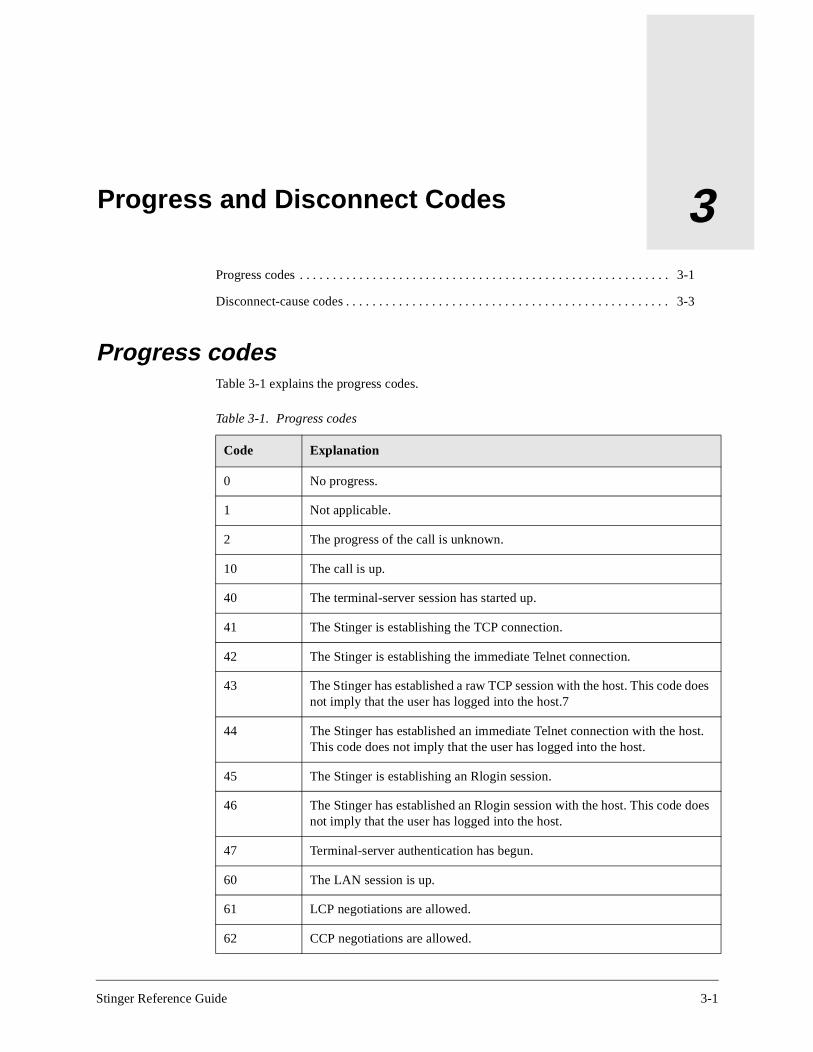
Stinger Reference Guide
3
Progress and Disconnect CodesProgress codesTable 3-1 explains the progress codes.
Progress codes . . . . . . . . . . . . . . . . . . . . . . . . . . . . . . . . . . . . . . . . . . . . . . . . . . . . . . . . 3-1
Disconnect-cause codes . . . . . . . . . . . . . . . . . . . . . . . . . . . . . . . . . . . . . . . . . . . . . . . . . 3-3
Table 3-1. Progress codes
Code Explanation
0 No progress.
1 Not applicable.
2 The progress of the call is unknown.
10 The call is up.
40 The terminal-server session has started up.
41 The Stinger is establishing the TCP connection.
42 The Stinger is establishing the immediate Telnet connection.
43 The Stinger has established a raw TCP session with the host. This code does not imply that the user has logged into the host.7
44 The Stinger has established an immediate Telnet connection with the host. This code does not imply that the user has logged into the host.
45 The Stinger is establishing an Rlogin session.
46 The Stinger has established an Rlogin session with the host. This code does not imply that the user has logged into the host.
47 Terminal-server authentication has begun.
60 The LAN session is up.
61 LCP negotiations are allowed.
62 CCP negotiations are allowed.
3-1

Progress and Disconnect CodesProgress codes
63 IPNCP negotiations are allowed.
65 LCP is in the Open state.
66 CCP is in the Open state.
67 IPNCP is in the Open state.
68 BNCP is in the Open state.
69 LCP is in the Initial state.
70 LCP is in the Starting state.
71 LCP is in the Closed state.
72 LCP is in the Stopped state.
73 LCP is in the Closing state.
74 LCP is in the Stopping state.
75 LCP is in the Request Sent state.
76 LCP is in the ACK Received state.
77 LCP is in the ACK Sent state.
82 BACP is being opened.
83 BACP is in an Open state.
84 CBCP is being opened.
85 CBCP is in an Open state.
90 The unit has accepted a V.110 call.
91 The V.110 call is in an Open state.
92 The V.110 call is in a carrier state.
93 The V.110 call is in a reset state.
94 The V.110 call is in a closed state.
100 The unit has determined that the call requires callback.
101 Authentication failed.
102 The remote authentication server timed out.
Table 3-1. Progress codes (continued)
Code Explanation
3-2 Stinger Reference Guide
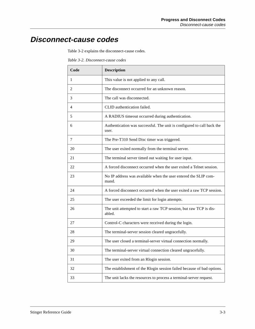
Progress and Disconnect CodesDisconnect-cause codes
Disconnect-cause codesTable 3-2 explains the disconnect-cause codes.
Table 3-2. Disconnect-cause codes
Code Description
1 This value is not applied to any call.
2 The disconnect occurred for an unknown reason.
3 The call was disconnected.
4 CLID authentication failed.
5 A RADIUS timeout occurred during authentication.
6 Authentication was successful. The unit is configured to call back the user.
7 The Pre-T310 Send Disc timer was triggered.
20 The user exited normally from the terminal server.
21 The terminal server timed out waiting for user input.
22 A forced disconnect occurred when the user exited a Telnet session.
23 No IP address was available when the user entered the SLIP com-mand.
24 A forced disconnect occurred when the user exited a raw TCP session.
25 The user exceeded the limit for login attempts.
26 The unit attempted to start a raw TCP session, but raw TCP is dis-abled.
27 Control-C characters were received during the login.
28 The terminal-server session cleared ungracefully.
29 The user closed a terminal-server virtual connection normally.
30 The terminal-server virtual connection cleared ungracefully.
31 The user exited from an Rlogin session.
32 The establishment of the Rlogin session failed because of bad options.
33 The unit lacks the resources to process a terminal-server request.
Stinger Reference Guide 3-3
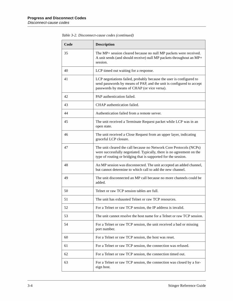
Progress and Disconnect CodesDisconnect-cause codes
35 The MP+ session cleared because no null MP packets were received. A unit sends (and should receive) null MP packets throughout an MP+ session.
40 LCP timed out waiting for a response.
41 LCP negotiations failed, probably because the user is configured to send passwords by means of PAP, and the unit is configured to accept passwords by means of CHAP (or vice versa).
42 PAP authentication failed.
43 CHAP authentication failed.
44 Authentication failed from a remote server.
45 The unit received a Terminate Request packet while LCP was in an open state.
46 The unit received a Close Request from an upper layer, indicating graceful LCP closure.
47 The unit cleared the call because no Network Core Protocols (NCPs) were successfully negotiated. Typically, there is no agreement on the type of routing or bridging that is supported for the session.
48 An MP session was disconnected. The unit accepted an added channel, but cannot determine to which call to add the new channel.
49 The unit disconnected an MP call because no more channels could be added.
50 Telnet or raw TCP session tables are full.
51 The unit has exhausted Telnet or raw TCP resources.
52 For a Telnet or raw TCP session, the IP address is invalid.
53 The unit cannot resolve the host name for a Telnet or raw TCP session.
54 For a Telnet or raw TCP session, the unit received a bad or missing port number.
60 For a Telnet or raw TCP session, the host was reset.
61 For a Telnet or raw TCP session, the connection was refused.
62 For a Telnet or raw TCP session, the connection timed out.
63 For a Telnet or raw TCP session, the connection was closed by a for-eign host.
Table 3-2. Disconnect-cause codes (continued)
Code Description
3-4 Stinger Reference Guide
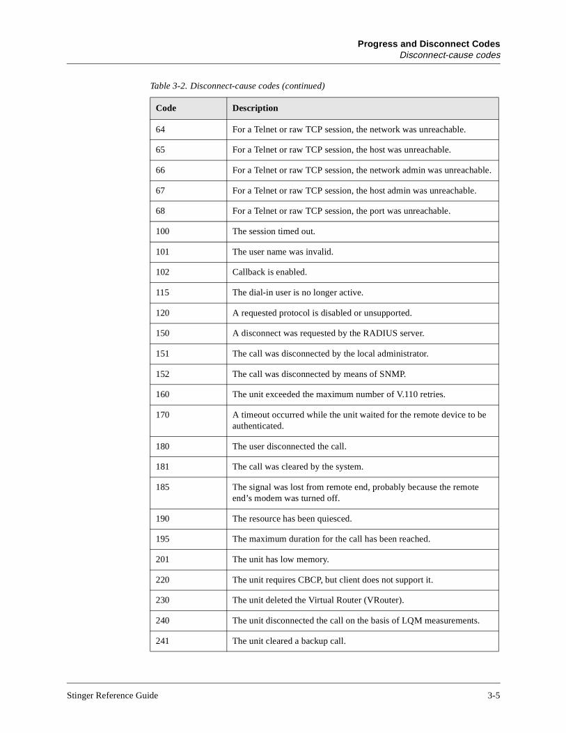
Progress and Disconnect CodesDisconnect-cause codes
64 For a Telnet or raw TCP session, the network was unreachable.
65 For a Telnet or raw TCP session, the host was unreachable.
66 For a Telnet or raw TCP session, the network admin was unreachable.
67 For a Telnet or raw TCP session, the host admin was unreachable.
68 For a Telnet or raw TCP session, the port was unreachable.
100 The session timed out.
101 The user name was invalid.
102 Callback is enabled.
115 The dial-in user is no longer active.
120 A requested protocol is disabled or unsupported.
150 A disconnect was requested by the RADIUS server.
151 The call was disconnected by the local administrator.
152 The call was disconnected by means of SNMP.
160 The unit exceeded the maximum number of V.110 retries.
170 A timeout occurred while the unit waited for the remote device to be authenticated.
180 The user disconnected the call.
181 The call was cleared by the system.
185 The signal was lost from remote end, probably because the remote end’s modem was turned off.
190 The resource has been quiesced.
195 The maximum duration for the call has been reached.
201 The unit has low memory.
220 The unit requires CBCP, but client does not support it.
230 The unit deleted the Virtual Router (VRouter).
240 The unit disconnected the call on the basis of LQM measurements.
241 The unit cleared a backup call.
Table 3-2. Disconnect-cause codes (continued)
Code Description
Stinger Reference Guide 3-5


Index? command, 1-1
A
accountingRADIUS, 2-148, 2-227
addressesBOOTP-Enabled, 2-41device address, 2-100, 2-174, 2-176Device-Address, 2-63Ethernet Media Access Control, 2-114gateway for static route, 2-84interface, 2-92IP address on Ethernet, 2-94IP on a WAN link, 2-157IP, system, 2-203IP-Direct, 2-95numbered interfaces on, 2-107RARP-Enabled, 2-153SNMP manager, 2-87static routes in, 2-84
administering devices, 1-10administering SNMP interfaces, 1-22Admin-State-Perm-If
Desired-Trap-State, 2-62Inet-Profile-Type, 2-91SNMP-Interface, 2-182Station, 2-198
Admin-State-Phys-IfDesired-State, 2-62Desired-Trap-State, 2-62Slot-Type, 2-179SNMP-Interface, 2-182
AlarmAction, 2-9
Alarm-LED-Major, 2-14Alarm-LED-Minor, 2-14Alarm-Relay-Major, 2-14Alarm-Relay-Major-Duration, 2-15Alarm-Relay-Minor, 2-15Alarm-Relay-Minor-Duration, 2-15
Enabled, 2-71Event, 2-76Name, 2-126Physical-Address, 2-136
alarm relaymajor and minor, 2-14
AL-DMTFast-Path-Config, 2-81
Max-Bitrate-Down, 2-118Max-Bitrate-Up, 2-118Min-Bitrate-Down, 2-121Min-Bitrate-Up, 2-122Planned-Bitrate-Down, 2-138Planned-Bitrate-Up, 2-138
Interleave-Path-Config, 2-93Max-Bitrate-Down, 2-118Max-Bitrate-Up, 2-118Max-Delay-Down, 2-118Max-Delay-Up, 2-119Min-Bitrate-Down, 2-121Min-Bitrate-Up, 2-122Planned-Bitrate-Down, 2-138Planned-Bitrate-Up, 2-138
Line-Config, 2-103Line-Code, 2-102Line-Latency-Down, 2-103Max-Aggr-Power-Level-Down, 2-117Max-Aggr-Power-Level-Up, 2-117Max--Power-Spectral-Density, 2-119Nailed-Group, 2-125Rate-Adapt-Mode-Down, 2-153Rate-Adapt-Mode-Up, 2-154VP-Switching-VPI, 2-231
Line-State, 2-104Margin-Config, 2-116
Max-Add-Noise-Margin-Down, 2-116Max-Add-Noise-Margin-Up, 2-117Min-Noise-Margin-Down, 2-122Min-Noise-Margin-Up, 2-122RA-Downshift-Int-Down, 2-151RA-Downshift-Int-Up, 2-152RA-Downshift-Margin-Down, 2-152RA-Downshift-Margin-Up, 2-152RA-Upshift-Int-Down, 2-154RA-Upshift-Int-Up, 2-154RA-Upshift-Margin-Down, 2-155RA-Upshift-Margin-Up, 2-155Target-Noise-Margin-Down, 2-205Target-Noise-Margin-Up, 2-205
Name, 2-126Physical-Address, 2-136Physical-Status
Accum-Bit-Error, 2-9Num-Sec-Invalid, 2-128Num-Sec-Valid, 2-128
Stinger Reference Guide Index-1

IndexB
AL-DMT-StatPhysical-Statistic, 2-137
Attenuation-Down, 2-27Attenuation-Up, 2-27Far-End-CRC, 2-79Far-End-FEC, 2-80Far-End-HEC, 2-80Line-Up-Timer, 2-105Near-End-CRC, 2-126Near-End-FEC, 2-126Near-End-HEC, 2-127Noise-Margin-Down, 2-128Noise-Margin-Up, 2-128Output-Power-Down, 2-131Output-Power-Up, 2-131RX-Signal-Present, 2-164Self-Test, 2-170Up-Down-Cntr, 2-222
Physical-Status, 2-137ANSI-ADSL-Ver, 2-22Dev-Line-State, 2-66Down-Stream-Latency, 2-68Down-Stream-Rate, 2-68Firmware-Ver, 2-82Hardware-Ver, 2-85IF-Group-Index, 2-89Initial-ADSL-Ver, 2-92Modem-Hw-State, 2-123Unit-Type, 2-221Up-Stream-Latency, 2-222Up-Stream-Rate, 2-223
Answer-DefaultsEnabled, 2-71Force-56Kbps, 2-82IP-Answer, 2-95
Routing-Metric, 2-162VJ-Header-Prediction, 2-230
Profiles-Required, 2-142Session-Info, 2-173
Idle-Timer, 2-89Max-Call-Duration, 2-118TS-Idle-Mode, 2-217TS-Idle-Timer, 2-217
Use-Answer-For-All-Defaults, 2-223ARP, Proxy-Mode, 2-144ARPtable command, 1-3ATM-Config
Bandwidth-ConfigBandwidth-Config N, 2-36
Allow-Guaranteed-Up-Stream-Bandwidth, 2-18Allow-Max-Up-Stream-Bandwidth, 2-18
Slot-VPI-VCI-Range, 2-180Slot-VPI-VCI-Range N, 2-181
ATMPVC-StatCircuit-Name, 2-51Current-State, 2-58Magic-Keys, 2-114PVC-Type, 2-144, 2-229VCC-Members, 2-228
VCC-Members N, 2-229Port, 2-139Slot-Number, 2-177VCI, 2-229
VP-Switching, 2-231ATM-QoS
AAL-Type, 2-2Contract-Name, 2-56Early-Packet-Discard, 2-71Partial-Packet-Discard, 2-132QoS-Class, 2-145
ATMtrunk command, 1-5ATMTrunkReset command, 1-4ATMVCC-Stat
Circuit-Name, 2-51Current-State, 2-58Magic Key, 2-114VCC-Ident, 2-228
Port, 2-139Slot-Number, 2-177VCI, 2-229
VCC-Type, 2-229VP-Switching, 2-231
Auth command, 1-6authentication services
RADIUS, 2-149Auth-Key, 2-30
B
Bandwidth-StatsActive-Upstream-Bandwidth-On-Trunks, 2-11Max-Upstream-Bandwidth, 2-120Standby-Upstream-Bandwidth-On-Trunks, 2-197
Base, 2-38Advanced-Agent-Enabled, 2-12AIM-Enabled, 2-12Countries-Enabled, 2-56Data-Call-Enabled, 2-59D-Channel-Enabled, 2-61Hardware-Level, 2-85MAXLink-Client-Enabled, 2-119Multi-Rate-Enabled, 2-123Network-Management-Enabled, 2-127PHS-Support, 2-135R2-Signaling-Enabled, 2-147Selectools-Enabled, 2-170Serial-Number, 2-171Software-Level, 2-182Software-Revision, 2-183Software-Version, 2-183Switched-Enabled, 2-200VOIP-Enabled, 2-231
billing. See Telco settings, RADIUSBOOTP, 2-41
Index-2 Stinger Reference Guide

IndexC
C
call managementAnalog-Encoding, 2-21Idle-Logout, 2-89Parallel-Dialing, 2-132Single-File-Incoming, 2-174System-Rmt-Mgmt, 2-204Use-Trunk-Groups, 2-226
Called-Number-Type, 2-45Call-Logging, 2-46
Call-Log-Enable, 2-46Call-Log-Host-N, 2-47Call-Log-ID-Base, 2-48Call-Log-Key, 2-48Call-Log-Limit-Retry, 2-49Call-Log-Port, 2-49Call-Log-RADIUS-Compat, 2-49Call-Log-Reset-Time, 2-50Call-Log-Stop-Only, 2-50Call-Log-Timeout, 2-50
cause codesprogress of disconnection, 3-3
Clear command, 1-6Clock-Source command, 1-7Clr-History command, 1-8Code-level commands
Format, 1-16Fsck, 1-17
commands?, 1-1ARPtable, 1-3ATMTrunkReset, 1-4ATMtrunks, 1-5Auth, 1-6Clear, 1-6Clock-Source, 1-7Clr-History, 1-8Connection, 1-8Date, 1-9Debug, 1-9Delete, 1-10Device, 1-10Dir, 1-11Dircode, 1-12DMTALDSLlines, 1-13Ether-Display, 1-15Fatal-History, 1-16Format, 1-16Fsck, 1-17Get, 1-18Help, 1-21If-Admin, 1-22IProute, 1-23Line, 1-25
List, 1-27Load, 1-29Log, 1-31Netstat, 1-33New, 1-39NSlookup, 1-42NVRAM, 1-42OAMloop, 1-43Open, 1-44Ping, 1-45Quit, 1-46Read, 1-47Refresh, 1-48Reset, 1-48Save, 1-49Screen, 1-51SDSLlines, 1-51Set, 1-53Show, 1-53Slot, 1-54Status, 1-55Telnet, 1-56Terminal-Server, 1-57Traceroute, 1-58Uptime, 1-59Userstat, 1-60Version, 1-62View, 1-62Which, 1-63Whoami, 1-64Write, 1-64
configurationbackup to file, 1-49restoring from file, 1-29
Connection, 2-54ATM-Connect-Options
ATM1483Type, 2-23ATM-Enabled, 2-24Nailed-Group, 2-125QoS-Contract, 2-145VCI, 2-229VPI, 2-231VP-Switching, 2-233
ATM-OptionsATM1483Type, 2-23ATM-Enabled, 2-24Nailed-Group, 2-125QoS-Contract, 2-145VCI, 2-229VPI, 2-231VP-Switching, 2-233
ATM-QoS-OptionsUsr-Dn-Stream-Contract, 2-227Usr-Up-Stream-Contract, 2-227
CalledNumber, 2-45Called-Number-Type, 2-45CLID, 2-52Dial-Number, 2-66
Stinger Reference Guide Index-3

IndexD
Connection (continued)Encapsulation-Protocol, 2-72Framed-Only, 2-83IP-Options, 2-98, 2-214
Client-Default-Gateway, 2-52Down-Preference, 2-68IF-Remote-Address, 2-90IP-Direct, 2-95IP-Routing-Enabled, 2-99Local-Address, 2-107Preference, 2-140Private-Route, 2-142Remote-Address, 2-157RIP, 2-159Routing-Metric, 2-162Source-IP-Check, 2-193Temporary-Route, 2-209TOS-Options
Active, 2-10Apply-To, 2-22Precedence, 2-140Type-of-Service, 2-219
VJ-Header-Prediction, 2-230Session-Options, 2-173
Backup, 2-36Idle-Timer, 2-89Max-Call-Duration, 2-118RX-Data-Rate-Limit, 2-164Ses-Rate-Mode, 2-171Ses-Rate-Type, 2-172Ses-SDSL-Rate, 2-172TS-Idle-Mode, 2-217TS-Idle-Timer, 2-217TX-Data-Rate-Limit, 2-218
Station, 2-198Telco-Options, 2-206
Answer-Originate, 2-22Billing-Number, 2-40Data-Service, 2-60Nailed-Groups, 2-125Transit-Number, 2-215
UsrRad-Options, 2-227Acct-Host, 2-3Acct-ID-Base, 2-3Acct-Key, 2-4Acct-Port, 2-5Acct-Timeout, 2-8Acct-Type, 2-9
Connection command, 1-8Contact, 2-55control modules
interface-independent address, 2-97
D
Date command, 1-9Debug command, 1-9Delete command, 1-10
Device command, 1-10device information
Device-State, 2-64Reqd-State, 2-158Up-Status, 2-222
Device-Address, components of, 2-100, 2-174, 2-176Device-State, 2-64
Device-Address, 2-63Device-State, 2-64Reqd-State, 2-158Up-Status, 2-222
Device-SummaryDisabled-Count, 2-67Operational-Count, 2-130Total-Count, 2-214
Diagnostic-level commandsATMTrunkReset, 1-4Clock-Source, 1-7Debug, 1-9Device, 1-10Ether-Display, 1-15If-Admin, 1-22NSlookup, 1-42OAMloop, 1-43Open, 1-44Ping, 1-45Slot, 1-54Telnet, 1-56Traceroute, 1-58
dial number for outbound connections, 2-66Dir command, 1-11Dircode command, 1-12disconnect cause codes, 3-3DMTALDSLlines command, 1-13DNS
Domain-Name, 2-67Sec-Domain-Name, 2-167
DNS lookups, 1-42DS3-ATM
AIS-Receive, 2-12Enabled, 2-71Line-Config
Clock-Priority, 2-53Clock-Source, 2-53Framer-Mode, 2-83High-Tx-Output, 2-86Loopback, 2-112Nailed-Group, 2-125Spare-Physical-Address, 2-194Sparing-Mode, 2-195VC-Switching-VPI, 2-230VPI-VCI-Range, 2-232
Line-State, 2-104Loss-Of-Frame, 2-113Loss-Of-Signal, 2-113
Index-4 Stinger Reference Guide
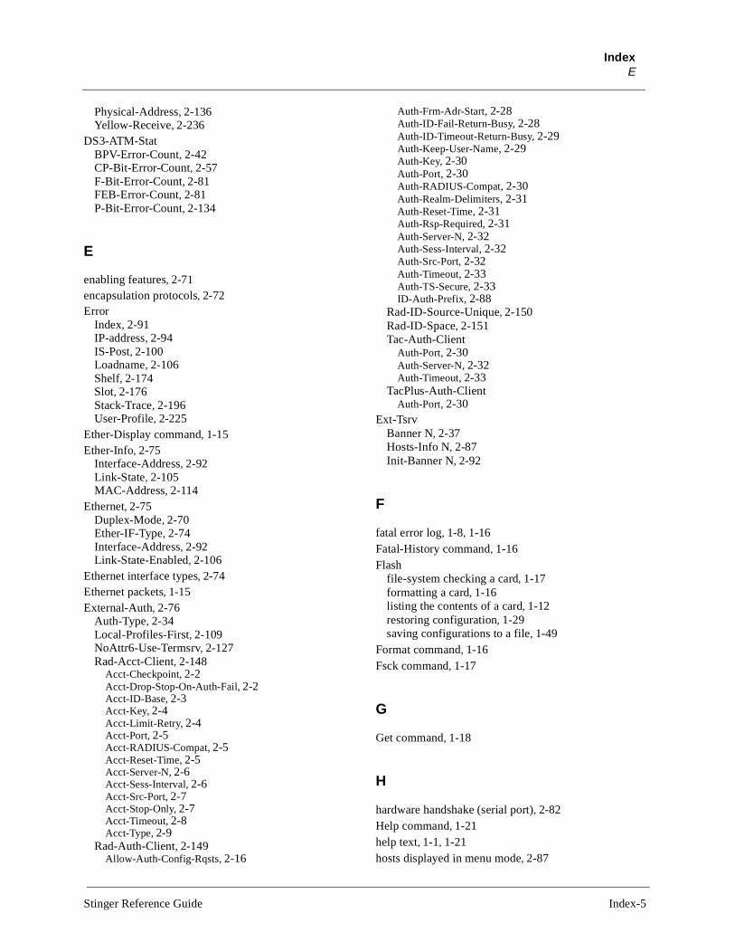
IndexE
Physical-Address, 2-136Yellow-Receive, 2-236
DS3-ATM-StatBPV-Error-Count, 2-42CP-Bit-Error-Count, 2-57F-Bit-Error-Count, 2-81FEB-Error-Count, 2-81P-Bit-Error-Count, 2-134
E
enabling features, 2-71encapsulation protocols, 2-72Error
Index, 2-91IP-address, 2-94IS-Post, 2-100Loadname, 2-106Shelf, 2-174Slot, 2-176Stack-Trace, 2-196User-Profile, 2-225
Ether-Display command, 1-15Ether-Info, 2-75
Interface-Address, 2-92Link-State, 2-105MAC-Address, 2-114
Ethernet, 2-75Duplex-Mode, 2-70Ether-IF-Type, 2-74Interface-Address, 2-92Link-State-Enabled, 2-106
Ethernet interface types, 2-74Ethernet packets, 1-15External-Auth, 2-76
Auth-Type, 2-34Local-Profiles-First, 2-109NoAttr6-Use-Termsrv, 2-127Rad-Acct-Client, 2-148
Acct-Checkpoint, 2-2Acct-Drop-Stop-On-Auth-Fail, 2-2Acct-ID-Base, 2-3Acct-Key, 2-4Acct-Limit-Retry, 2-4Acct-Port, 2-5Acct-RADIUS-Compat, 2-5Acct-Reset-Time, 2-5Acct-Server-N, 2-6Acct-Sess-Interval, 2-6Acct-Src-Port, 2-7Acct-Stop-Only, 2-7Acct-Timeout, 2-8Acct-Type, 2-9
Rad-Auth-Client, 2-149Allow-Auth-Config-Rqsts, 2-16
Auth-Frm-Adr-Start, 2-28Auth-ID-Fail-Return-Busy, 2-28Auth-ID-Timeout-Return-Busy, 2-29Auth-Keep-User-Name, 2-29Auth-Key, 2-30Auth-Port, 2-30Auth-RADIUS-Compat, 2-30Auth-Realm-Delimiters, 2-31Auth-Reset-Time, 2-31Auth-Rsp-Required, 2-31Auth-Server-N, 2-32Auth-Sess-Interval, 2-32Auth-Src-Port, 2-32Auth-Timeout, 2-33Auth-TS-Secure, 2-33ID-Auth-Prefix, 2-88
Rad-ID-Source-Unique, 2-150Rad-ID-Space, 2-151Tac-Auth-Client
Auth-Port, 2-30Auth-Server-N, 2-32Auth-Timeout, 2-33
TacPlus-Auth-ClientAuth-Port, 2-30
Ext-TsrvBanner N, 2-37Hosts-Info N, 2-87Init-Banner N, 2-92
F
fatal error log, 1-8, 1-16Fatal-History command, 1-16Flash
file-system checking a card, 1-17formatting a card, 1-16listing the contents of a card, 1-12restoring configuration, 1-29saving configurations to a file, 1-49
Format command, 1-16Fsck command, 1-17
G
Get command, 1-18
H
hardware handshake (serial port), 2-82Help command, 1-21help text, 1-1, 1-21hosts displayed in menu mode, 2-87
Stinger Reference Guide Index-5

IndexI
I
ICMP echo-request, 1-45idle time, monitoring, 2-89, 2-217If-Admin command, 1-22Immediate-Mode-Options, 2-91Interface-Address, 2-92Interface-Address, components, 2-92interfaces
how addressed, 2-97IP on Ethernet, 2-94remote station name, 2-198
IPsoft interface address, 2-97
IP direct, 2-95IP interface table, 1-33IP routing table, 1-33IP-Global, 2-95
BOOTP-Enabled, 2-41BOOTP-Relay, 2-41
Active, 2-10BOOTP-Servers, 2-41
Dialout-Poison, 2-67Domain-Name, 2-67Drop-Source-Routed-Ip-Packets, 2-69ICMP-Reply-Directed-Bcast, 2-88Ignore-Def-Route, 2-90Ignore-ICMP-Redirects, 2-90RARP-Enabled, 2-153RIP-Policy, 2-160RIP-Pref, 2-160RIP-Tag, 2-161Sec-Domain-Name, 2-167Static-Pref, 2-197Summarize-RIP-Routes, 2-199Suppress-Host-Routes, 2-199System-IP-Addr, 2-203Telnet-Password, 2-208UDP-Cksum, 2-220User-Profile, 2-225
IP-Interface, 2-97Directed-Broadcast-Allowed, 2-67Interface-Address, 2-92IP-Address, 2-94Management-Only-Interface, 2-115Proxy-Mode, 2-144RIP-Mode, 2-160
IP-Route, 2-99Active-Route, 2-10Gateway-Address, 2-84Metric, 2-121Name, 2-126Preference, 2-140Private-Route, 2-142
IProute command, 1-23
L
LIMsdisplaying nailed group for port, 1-63displaying port for nailed group, 1-63
LIM-Sparing-ConfigManually-Spared-Slot-Number, 2-115Spare-Slot-Number, 2-195Sparing-Mode, 2-195
LIM-Sparing-StatusSpared-Slot-Number, 2-194Spare-Slot-Number, 2-195Sparing-Mode, 2-195
Line command, 1-25List command, 1-27Load command, 1-29loading code, 1-29Load-Select
DS3-ATM, 2-69Enet, 2-72Enet2, 2-73SDSL, 2-166UDS3, 2-220Unknown-Cards, 2-221
location, 2-109Log, 2-109
Auxiliary-Syslog, 2-35Auxiliary-Syslog N, 2-35
Facility, 2-79Host, 2-86Port, 2-139Syslog-Level, 2-201
Call-Info, 2-46Facility, 2-79Log-Call-Progress, 2-110Log-Software-Version, 2-112Port, 2-139Save-Level, 2-165Save-Number, 2-165Syslog-Enabled, 2-200Syslog-Level, 2-201
Log command, 1-31log messages
level displayed for a user login, 2-111recorded in an ASCII file, 2-200
loginsAuto-Logout, 2-34Banner, 2-37Buffer-Chars, 2-43Clear-Call, 2-51Clear-Screen, 2-51
Index-6 Stinger Reference Guide

IndexM
enabling Ping, 2-138enabling SLIP, 2-175enabling SLIP-BOOTP, 2-175enabling TCP command, 2-206enabling Telnet, 2-207enabling Traceroute command, 2-215Idle-Logout, 2-89level of log messages displayed, 2-111Login-Prompt, 2-111network host, 2-86Password-Prompt, 2-133Prompt, 2-143Prompt-Format, 2-143Silent-Mode, 2-174start with Menu mode, 2-197System-Password, 2-203TCP port for logins, 2-139Terminal-Type, 2-210Third-Login-Prompt, 2-212Third-Prompt-Sequence, 2-212User-Profile, 2-225
M
major alarm LED, 2-14
major alarm relay, 2-14
memory, clearing, 1-42
menu modeconfiguring, 2-121default for logins, 2-197description of hosts, 2-211obtaining from RADIUS, 2-158
N
nailed groupsdisplaying for an interface, 1-63
nailed-up connectionsBackup, 2-36Nailed-Groups, 2-125Temporary-Route, 2-209
names, 2-126
Netstat command, 1-33
New command, 1-39
NSlookup command, 1-42
numbered interfaces, Local-Address, 2-107
NVRAM command, 1-42
O
OAMloop command, 1-43OC3-ATM
Enabled, 2-71Line Config
RX-Cell-Payload-Descramble-Disabled, 2-163RX-Descramble-Disabled, 2-164TX-Cell-Payload-Scramble-Disabled, 2-217TX-Scramble-Disabled, 2-218
Line-Config, 2-103Clock-Priority, 2-53Clock-Source, 2-53Framer-Rate, 2-83Loopback, 2-112Loop-Timing, 2-113Nailed-Group, 2-125VC-Switching-VPI, 2-230VPI-VCI-Range, 2-232
Name, 2-126Physical-Address, 2-136Spare-Physical-Address, 2-194Sparing-State, 2-195
OC3-ATM-StatAIS-Receive, 2-12FIFO-Overflow-Counter, 2-81Frequency-Justification-Count, 2-83HEC-Cell-Drop-Counter, 2-85Idle-Cell-Counter, 2-88Interval-Performance-Monitoring, 2-94
SONET-Far-End-Line-Coding-Violations, 2-183SONET-Far-End-Line-Errored-Seconds, 2-184SONET-Far-End-Line-Severely-Errored-Seconds, 2-184SONET-Far-End-Line-Unavailable-Seconds, 2-185SONET-Far-End-Path-Coding-Violations, 2-185SONET-Far-End-Path-Errored-Seconds, 2-186SONET-Far-End-Path-Severely-Errored-Seconds, 2-186SONET-Far-End-Path-Unavailable-Seconds, 2-187SONET-Line-Coding-Violations, 2-187SONET-Line-Errored-Seconds, 2-188SONET-Line-Severely-Errored-Seconds, 2-188SONET-Line-Unavailable-Seconds, 2-189SONET-Path-Coding-Violations, 2-189SONET-Path-Errored-Seconds, 2-190SONET-Path-Severely-Errored-Seconds, 2-190SONET-Path-Unavailable-Seconds, 2-191SONET-Section-Coding-Violations, 2-191SONET-Section-Errored-Seconds, 2-192SONET-Section-Severely-Errored-Framing-Seconds,
2-192SONET-Section-Severely-Errored-Seconds, 2-193
Line-State, 2-104Loss-Of-Cell-Delineation, 2-113Loss-Of-Frame, 2-113Loss-Of-Signal, 2-113Out-Of-Cell-Delineation, 2-130Out-Of-Frame, 2-131Path-State, 2-133Performance-Monitoring, 2-134
Stinger Reference Guide Index-7

IndexP
OC3-ATM-Stat (continued)SONET-Far-End-Line-Coding-Violations, 2-183SONET-Far-End-Line-Errored-Seconds, 2-184SONET-Far-End-Line-Severely-Errored-Seconds, 2-184SONET-Far-End-Line-Unavailable-Seconds, 2-185SONET-Far-End-Path-Coding-Violations, 2-185SONET-Far-End-Path-Errored-Seconds, 2-186SONET-Far-End-Path-Severely-Errored-Seconds, 2-186SONET-Far-End-Path-Unavailable-Seconds, 2-187SONET-Line-Coding-Violations, 2-187SONET-Line-Errored-Seconds, 2-188SONET-Line-Severely-Errored-Seconds, 2-188SONET-Line-Unavailable-Seconds, 2-189SONET-Path-Coding-Violations, 2-189SONET-Path-Errored-Seconds, 2-190SONET-Path-Severely-Errored-Seconds, 2-190SONET-Path-Unavailable-Seconds, 2-191SONET-Section-Coding-Violations, 2-191SONET-Section-Errored-Seconds, 2-192SONET-Section-Severely-Errored-Framing-Seconds,
2-192SONET-Section-Severely-Errored-Seconds, 2-193
Physical-Address, 2-136RACP-CHCS-Error-Count, 2-147RACP-RX-Cell-Count, 2-147RACP-UCHCS-Error-Count, 2-148RLOP-BIP-Error-Count, 2-162RLOP-FEBE-Error-Count, 2-162RPOP-BIP-Error-Count, 2-162RPOP-FEBE-Error-Count, 2-163RSOP-BIP-Error-Count, 2-163Section-State, 2-168Spare-Physical-Address, 2-194Sparing-State, 2-195TACP-TX-Cell-Count, 2-205Valid-Cell-Counter, 2-228Yellow-Receive, 2-236
Open command, 1-44
P
passwordsfor Telnet, 2-208for terminal-server logins, 2-203viewing, 2-18
permissionsAllow-Code, 2-17Allow-Diagnostic, 2-17Allow-Password, 2-18Allow-System, 2-19Allow-Termserv, 2-20Allow-Update, 2-20authenticating a profile, 1-6Whoami, 1-64
phone number for outbound calls, 2-66Physical-Address, components of, 2-100, 2-174, 2-176Ping command, 1-45
preferences, 2-140profiles
Base, 2-38Call-Logging, 2-46Connection, 2-54creating new, 1-39deleting, 1-10Device-State, 2-64displaying contents of, 1-18displaying working profile, 1-27Ether-Info, 2-75Ethernet, 2-75External-Auth, 2-76indexed by interface address, 2-97IP-Global, 2-95IP-Interface, 2-97IP-Route, 2-99listing, 1-11Log, 2-109modifying, 1-53reading into edit buffer, 1-46saving, 1-64SDSL, 2-166SDSL-Stat, 2-167Serial, 2-170Slot-Info, 2-177Slot-State, 2-178Slot-Type, 2-179SNMP, 2-181System, 2-202Terminal-Server, 2-210Timedate, 2-213Trap, 2-215User, 2-224
progress codes, 3-1Proxy ARP, 2-144
Q
Quit command, 1-46
R
RADIUS accounting, 2-148, 2-227Acct-Host, 2-3Acct-ID-Base, 2-3, 2-48Acct-Key, 2-4Acct-Port, 2-5Acct-Reset-Time, 2-5Acct-Server-N, 2-6Acct-Sess-Interval, 2-6Acct-Src-Port, 2-7Acct-Timeout, 2-8Acct-Type, 2-9
Index-8 Stinger Reference Guide
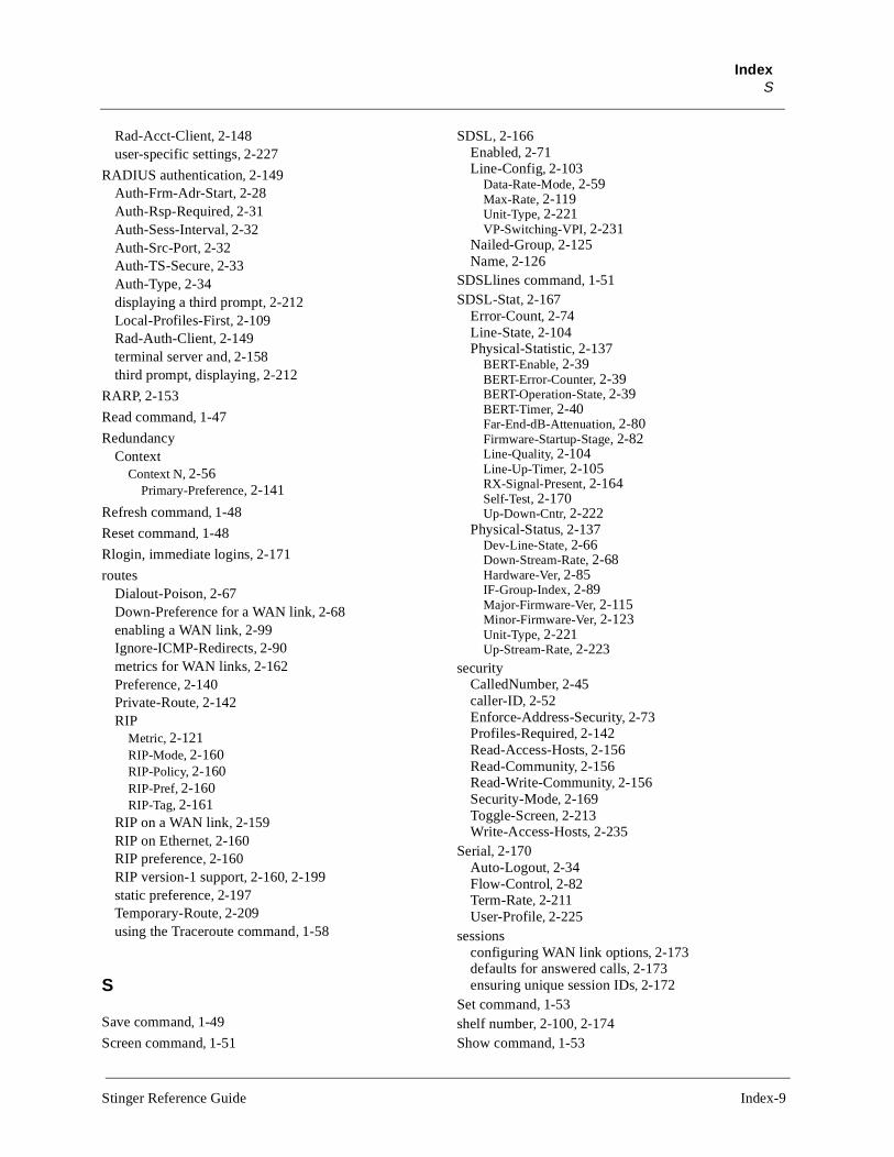
IndexS
Rad-Acct-Client, 2-148user-specific settings, 2-227
RADIUS authentication, 2-149Auth-Frm-Adr-Start, 2-28Auth-Rsp-Required, 2-31Auth-Sess-Interval, 2-32Auth-Src-Port, 2-32Auth-TS-Secure, 2-33Auth-Type, 2-34displaying a third prompt, 2-212Local-Profiles-First, 2-109Rad-Auth-Client, 2-149terminal server and, 2-158third prompt, displaying, 2-212
RARP, 2-153
Read command, 1-47
RedundancyContext
Context N, 2-56Primary-Preference, 2-141
Refresh command, 1-48
Reset command, 1-48
Rlogin, immediate logins, 2-171
routesDialout-Poison, 2-67Down-Preference for a WAN link, 2-68enabling a WAN link, 2-99Ignore-ICMP-Redirects, 2-90metrics for WAN links, 2-162Preference, 2-140Private-Route, 2-142RIP
Metric, 2-121RIP-Mode, 2-160RIP-Policy, 2-160RIP-Pref, 2-160RIP-Tag, 2-161
RIP on a WAN link, 2-159RIP on Ethernet, 2-160RIP preference, 2-160RIP version-1 support, 2-160, 2-199static preference, 2-197Temporary-Route, 2-209using the Traceroute command, 1-58
S
Save command, 1-49
Screen command, 1-51
SDSL, 2-166Enabled, 2-71Line-Config, 2-103
Data-Rate-Mode, 2-59Max-Rate, 2-119Unit-Type, 2-221VP-Switching-VPI, 2-231
Nailed-Group, 2-125Name, 2-126
SDSLlines command, 1-51SDSL-Stat, 2-167
Error-Count, 2-74Line-State, 2-104Physical-Statistic, 2-137
BERT-Enable, 2-39BERT-Error-Counter, 2-39BERT-Operation-State, 2-39BERT-Timer, 2-40Far-End-dB-Attenuation, 2-80Firmware-Startup-Stage, 2-82Line-Quality, 2-104Line-Up-Timer, 2-105RX-Signal-Present, 2-164Self-Test, 2-170Up-Down-Cntr, 2-222
Physical-Status, 2-137Dev-Line-State, 2-66Down-Stream-Rate, 2-68Hardware-Ver, 2-85IF-Group-Index, 2-89Major-Firmware-Ver, 2-115Minor-Firmware-Ver, 2-123Unit-Type, 2-221Up-Stream-Rate, 2-223
securityCalledNumber, 2-45caller-ID, 2-52Enforce-Address-Security, 2-73Profiles-Required, 2-142Read-Access-Hosts, 2-156Read-Community, 2-156Read-Write-Community, 2-156Security-Mode, 2-169Toggle-Screen, 2-213Write-Access-Hosts, 2-235
Serial, 2-170Auto-Logout, 2-34Flow-Control, 2-82Term-Rate, 2-211User-Profile, 2-225
sessionsconfiguring WAN link options, 2-173defaults for answered calls, 2-173ensuring unique session IDs, 2-172
Set command, 1-53shelf number, 2-100, 2-174Show command, 1-53
Stinger Reference Guide Index-9

IndexS
SLIP configuration, 2-175slot card sessions, 1-44slot cards, displaying status, 1-53Slot command, 1-54slot information
Current-State, 2-58Reqd-State, 2-158
slot number, 2-176Slot-Info, 2-177
Hardware-Level, 2-85Hardware-Rework-Count, 2-85Serial-Number, 2-171Slot-Address, 2-176Software-Level, 2-182Software-Release, 2-182Software-Revision, 2-183Software-Version, 2-183
Slot-State, 2-178Current-State, 2-58Reqd-State, 2-158Slot-Address, 2-176
Slot-Type, 2-179Slot-Address, 2-176
SNMP, 2-181Contact, 2-55CSM-Modem-Diag, 2-57Enabled, 2-71Enforce-Address-Security, 2-73Location, 2-109Read-Access-Hosts, 2-156Read-Community, 2-156Read-Write-Community, 2-156Read-Write-Enabled, 2-156traps
Alarm-Enabled, 2-14Ascend-Enabled, 2-23Authentication-Enabled, 2-28Coldstart-Enabled, 2-53Community-Name, 2-53Console-Enabled, 2-55Event-Overwrite-Enabled, 2-76Host-Address, 2-87LinkDown-Enabled, 2-105LinkUp-Enabled, 2-106Password-Enabled, 2-133Port-Enabled, 2-139Power-Supply-Enabled, 2-140RADIUS-Change-Enabled, 2-151Security-Enabled, 2-169Slot-Profile-Change-Enabled, 2-178Use-Exceeded-Enabled, 2-223Warmstart-Enabled, 2-234
Write-Access-Hosts, 2-235SNMP interfaces
administration, 1-22Device Address, 2-63
soft interface address, 2-97
SS7-GatewayDevice-ID, 2-64Enabled, 2-71Primary-IP-Address, 2-141Primary-TCP-Port, 2-142Secondary-IP-Address, 2-168Secondary-TCP-Port, 2-168
Status command, 1-55status windows
Bottom-Status, 2-42changing default contents, 1-62connection information, 1-8Default-Status, 2-61displaying and hiding, 1-55Left-Status, 2-101line information, 1-25log buffer, 1-31Top-Status, 2-214Up-Status, 2-222Use-Scroll-Regions, 2-226
Syslog, 1-31, 2-109, 2-200Syslog daemon, 2-79, 2-200System, 2-202
Analog-Encoding, 2-21Boot-SR-Version, 2-42Idle-Logout, 2-89Name, 2-126Parallel-Dialing, 2-132Perm-Conn-Upd-Mode, 2-135SessionID-Base, 2-172Single-File-Incoming, 2-174System-8k-Clock, 2-202System-Rmt-Mgmt, 2-204Userstat-Format, 2-226Use-Trunk-Groups, 2-226
system date and time, setting, 1-9system version, displaying, 1-62System-level commands
ARPtable, 1-3ATMtrunks, 1-5, 1-13Clr-History, 1-8Connection, 1-8Dir, 1-11Dircode, 1-12Fatal-History, 1-16Get, 1-18IProute, 1-23Line, 1-25List, 1-27Log, 1-31Netstat, 1-33New, 1-39Read, 1-46Refresh, 1-48SDSLlines, 1-51
Index-10 Stinger Reference Guide

IndexT
Set, 1-53Show, 1-53Status, 1-55Uptime, 1-59Userstat, 1-60Version, 1-62View, 1-62Which, 1-63
T
TCPfor immediate logins, 2-171port for immediate logins, 2-139
Telco settingsAnswer-Originate, 2-22Billing-Number, 2-40Data-Service, 2-60Transit-Number, 2-215
TelnetAuto-Telnet, 2-34hosts displayed in menu, 2-87immediate logins, 2-171Local-Echo, 2-108quitting, 1-46Telnet-Host-Auth, 2-207Telnet-Mode, 2-208Telnet-Password, 2-208using the Telnet command, 1-56
Telnet command, 1-56Terminal-Server, 2-210
immediate login host, 2-86Immediate-Mode-Options, 2-91
Service, 2-171Telnet-Host-Auth, 2-207
Menu-Mode-Options, 2-121Host-N, 2-87Remote-Configuration, 2-158Start-With-Menus, 2-197Text-N, 2-211Toggle-Screen, 2-213
monitoring idle time, 2-217obtaining menu from RADIUS, 2-158Security-Mode, 2-169SLIP-Mode-Configuration, 2-175
SLIP, 2-175SLIP-BOOTP, 2-175
Terminal-Mode-Configuration, 2-210Banner, 2-37Buffer-Chars, 2-43Clear-Call, 2-51Clear-Screen, 2-51Login-Prompt, 2-111Login-Timeout, 2-112Password-Prompt, 2-133Ping, 2-138
Prompt, 2-143Prompt-Format, 2-143Rlogin-Options, 2-161
Max-Source-Port, 2-120Min-Source-Port, 2-123
Silent-Mode, 2-174System-Password, 2-203TCP, 2-206Telnet-Options, 2-208
Auto-Telnet, 2-34Local-Echo, 2-108Telnet, 2-207Telnet-Mode, 2-208
Terminal-Type, 2-210Third-Login-Prompt, 2-212Third-Prompt-Sequence, 2-212Traceroute, 2-215
Termserv-level commands, Terminal-Server, 1-57
Timedate, 2-213Date, 2-61Time, 2-213
Traceroute command, 1-58
Trap, 2-215Alarm-Enabled, 2-14Ascend-Enabled, 2-23Authentication-Enabled, 2-28Coldstart-Enabled, 2-53Community-Name, 2-53Config-Change-Enabled, 2-54Console-Enabled, 2-55Event-Overwrite-Enabled, 2-76Host-Address, 2-87LinkDown-Enabled, 2-105LinkUp-Enabled, 2-106Name, 2-126Password-Enabled, 2-133Port-Enabled, 2-139Power-Supply-Enabled, 2-140Primary-SDTN-Empty-Enabled, 2-141RADIUS-Change-Enabled, 2-151Secondary-SDTN-Empty-Enabled, 2-167Security-Enabled, 2-169Slot-Profile-Change-Enabled, 2-178Suspect-Access-Resource-Enabled, 2-199Sys-Clock-Drift-Enabled, 2-200Use-Exceeded-Enabled, 2-223Warmstart-Enabled, 2-234Watchdog-Warning-Enabled, 2-234
trunk modulesdisplaying nailed group for port, 1-63displaying port for nailed group, 1-63
Stinger Reference Guide Index-11
IndexU
U
UDP checksums, 2-220
Update-level commandsDate, 1-9Delete, 1-10Load, 1-29NVRAM, 1-42Reset, 1-48Save, 1-49Screen, 1-51Write, 1-64
Uptime command, 1-59
User, 2-224Active-Enabled, 2-10Allow-Code, 2-17Allow-Diagnostic, 2-17Allow-Password, 2-18Allow-System, 2-19Allow-Termserv, 2-20Allow-Update, 2-20Bottom-Status, 2-42Default-Status, 2-61Idle-Logout, 2-89Left-Status, 2-101Log-Display-Level, 2-111Name, 2-126Password, 2-132Prompt, 2-143Screen-Length, 2-166Status-Length, 2-198Top-Status, 2-214Use-Scroll-Regions, 2-226
User-level commands?, 1-1Auth, 1-6Clear, 1-6Help, 1-21Quit, 1-46Whoami, 1-64
Userstat command, 1-60
V
Van Jacobsen header prediction, 2-230
Version command, 1-62
View command, 1-62
VT100 session, 1-6
W
Which command, 1-63Whoami command, 1-64Write command, 1-64
X
XON-XOFF (serial port), 2-82
Index-12 Stinger Reference Guide