Stihl Carburetor Manual - The Bakelite Radiothebakeliteradio.com/sawspares.com/stihl carburetor...
65
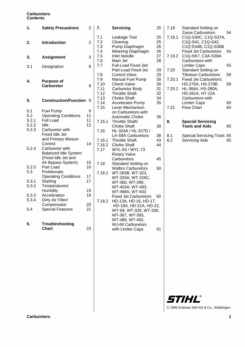
1. Safety Precautions 2 2. Introduction 2 3. Assignment 3 3.1 Designation 8 4. Purpose of Carburetor 8 5. Construction/Function 9 5.1 Fuel Pump 9 5.2 Operating Conditions 11 5.2.1 Full Load 11 5.2.2 Idle 12 5.2.3 Carburetor with Fixed Idle Jet and Primary Mixture Control 14 5.2.4 Carburetor with Balanced Idle System (Fixed Idle Jet and Air Bypass System) 15 5.2.5 Part Load 16 5.3 Problematic Operating Conditions 17 5.3.1 Starting 17 5.3.2 Temperatures/ Humidity 19 5.3.3 Acceleration 19 5.3.4 Dirty Air Filter/ Compensator 20 5.4 Special Features 21 6. Troubleshooting Chart 23 7. Servicing 25 7.1 Leakage Test 25 7.2 Cleaning 25 7.3 Pump Diaphragm 26 7.4 Metering Diaphragm 26 7.5 Inlet Needle 27 7.6 Main Jet 28 7.7 Full-Load Fixed Jet/ Part-Load Fixed Jet 29 7.8 Control Valve 29 7.9 Manual Fuel Pump 30 7.10 Check Valve 30 7.11 Carburetor Body 31 7.12 Throttle Shaft 32 7.13 Choke Shaft 34 7.14 Accelerator Pump 35 7.15 Lever Mechanism on Carburetors with Automatic Choke 36 7.15.1 Throttle Shaft/ Choke Shaft 38 7.16 HL-324A / HL-327D / LA-S8A Carburetors 38 7.16.1 Throttle Shaft 43 7.16.2 Choke Shaft 44 7.17 WYL-63 / WYL-73 Rotary Valve Carburetors 45 7.18 Standard Setting on Walbro Carburetors 50 7.18.1 WT-283B, WT-323, WT-325A, WT-326C, WT-360, WT-396, WT-403A, WT-493, WT-498A, WT-503 Fixed Jet Carburetors 50 7.18.2 HD-13A, HD-16, HD-17, HD-18A, HD-21A, HD-22, WY-69, WT-329, WT-330, WT-367, WT-393, WT-489, WT-492, WJ-69 Carburetors with Limiter Caps 51 7.19 Standard Setting on Zama Carburetors 54 7.19.1 C1Q-S30C, C1Q-S37A, C1Q-S41, C1Q-S42, C1Q-S34B, C1Q-S36B Fixed Jet Carburetors 54 7.19.2 C1Q-SK7, C3A-S39A Carburetors with Limiter Caps 55 7.20 Standard Setting on Tillotson Carburetors 59 7.20.1 Fixed Jet Carburetors: HS-275A, HS-279B 59 7.20.2 HL-366A, HS-280A, HS-281A, HT-12A Carburetors with Limiter Caps 60 7.21 Flow Chart 64 8. Special Servicing Tools and Aids 65 8.1 Special Servicing Tools 65 8.2 Servicing Aids 65 © 1999 Andreas Stihl AG & Co., Waiblingen Carburetors Contents Carburetors 1
Transcript of Stihl Carburetor Manual - The Bakelite Radiothebakeliteradio.com/sawspares.com/stihl carburetor...
1. Safety Precautions 2
2. Introduction 2
3. Assignment 3
3.1 Designation 8
4. Purpose ofCarburetor 8
5. Construction/Function 9
5.1 Fuel Pump 95.2 Operating Conditions 115.2.1 Full Load 115.2.2 Idle 125.2.3 Carburetor with
Fixed Idle Jetand Primary MixtureControl 14
5.2.4 Carburetor withBalanced Idle System(Fixed Idle Jet andAir Bypass System) 15
5.2.5 Part Load 165.3 Problematic
Operating Conditions 175.3.1 Starting 175.3.2 Temperatures/
Humidity 195.3.3 Acceleration 195.3.4 Dirty Air Filter/
Compensator 205.4 Special Features 21
6. TroubleshootingChart 23
7. Servicing 25
7.1 Leakage Test 257.2 Cleaning 257.3 Pump Diaphragm 267.4 Metering Diaphragm 267.5 Inlet Needle 277.6 Main Jet 287.7 Full-Load Fixed Jet/
Part-Load Fixed Jet 297.8 Control Valve 297.9 Manual Fuel Pump 307.10 Check Valve 307.11 Carburetor Body 317.12 Throttle Shaft 327.13 Choke Shaft 347.14 Accelerator Pump 357.15 Lever Mechanism
on Carburetors withAutomatic Choke 36
7.15.1 Throttle Shaft/Choke Shaft 38
7.16 HL-324A / HL-327D /LA-S8A Carburetors 38
7.16.1 Throttle Shaft 437.16.2 Choke Shaft 447.17 WYL-63 / WYL-73
Rotary ValveCarburetors 45
7.18 Standard Setting onWalbro Carburetors 50
7.18.1 WT-283B, WT-323,WT-325A, WT-326C,WT-360, WT-396,WT-403A, WT-493,WT-498A, WT-503Fixed Jet Carburetors 50
7.18.2 HD-13A, HD-16, HD-17,HD-18A, HD-21A, HD-22,
WY-69, WT-329, WT-330,WT-367, WT-393,WT-489, WT-492,WJ-69 Carburetorswith Limiter Caps 51
7.19 Standard Setting onZama Carburetors 54
7.19.1 C1Q-S30C, C1Q-S37A,C1Q-S41, C1Q-S42,C1Q-S34B, C1Q-S36BFixed Jet Carburetors 54
7.19.2 C1Q-SK7, C3A-S39ACarburetors withLimiter Caps 55
7.20 Standard Setting onTillotson Carburetors 59
7.20.1 Fixed Jet Carburetors:HS-275A, HS-279B 59
7.20.2 HL-366A, HS-280A,HS-281A, HT-12ACarburetors withLimiter Caps 60
7.21 Flow Chart 64
8. Special ServicingTools and Aids 65
8.1 Special Servicing Tools 658.2 Servicing Aids 65
© 1999 Andreas Stihl AG & Co., Waiblingen
CarburetorsContents
Carburetors 1
If the chainsaw or power toolis started up in the course ofrepairs or maintenance work,observe all local and country-specific safety regulations aswell as the safety precautionsand warnings in the owner’smanual.
Gasoline is an extremely flamm-able fuel and can be explosivein certain conditions.
Improper handling may result inburns or other serious injuries.
Warning ! Do not smoke or bringany fire or flame near the fuel. Allwork with fuel must be performedoutdoors only. Spilled fuel must bewiped away immediately.
Warning ! To avoid the risk ofaccidents and personl injury, takeextreme care when performingadjustments without the cuttingtool guard or deflector.
This service manual contains des-criptions of repair and servicingprocedures as well as functionaldiagrams of most carburetorsused in STIHL gasoline powertools.
While carrying out repair workyou should make use of the latestillustrated parts list of the powertool concerned. It shows the instal-led positions and the assembly se-quence of individual componentsand assemblies.Parts lists on microfilm andCD-ROM are always more upto date than printed lists.
A fault on the carburetor mayhave several causes. Consult thetroubleshooting chart - see 6.
Refer to the "Technical Informa-tion" bulletins for engineeringchanges which have been intro-duced since publication of thisservice manual. Technical informa-tion bulletins also supplement theparts list until an update is issued.
Service manuals and all technicalinformation bulletins describingengineering changes are intendedexclusively for the use of STIHLservicing dealers. They must notbe passed to third parties.
Symbols are used in the text andillustrations for greater clarity.
The meanings are as follows:
In the descriptions:
• = Action to be taken asshown in the illustration(above the text)
- = Action to be taken thatis not shown in theillustration(above the text)
In the illustrations:
= Pointer
= Direction of movement
Alway s use origina l STIHLreplacemen t parts.They can be identified by theSTIHL part number,the lögoand the STIHL parts symbol(The symbol may appear alone onsmall parts.
1. Safety 2. IntroductionPrecautions
2 Carburetors
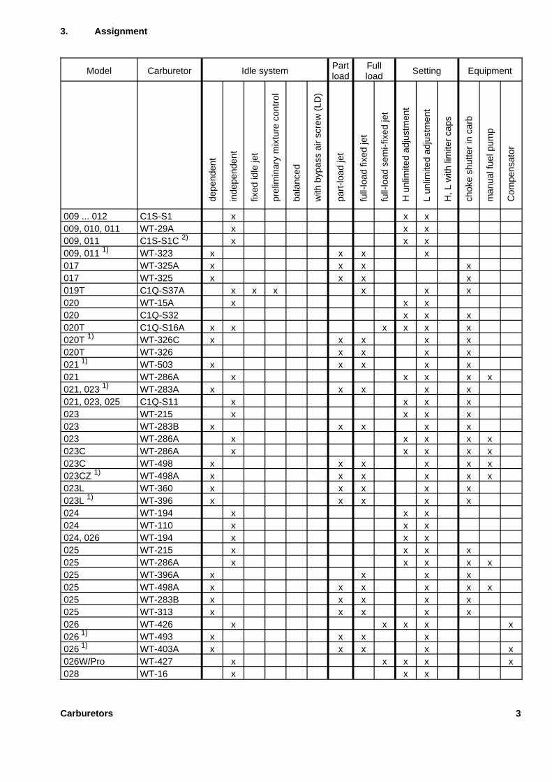
3. Assignment
Model Carburetor Idle system Partload
Fullload Setting Equipment
depe
nden
t
inde
pend
ent
fixed
idle
jet
prel
imin
ary
mix
ture
cont
rol
bala
nced
with
bypa
ssai
rsc
rew
(LD
)
part
-load
jet
full-
load
fixed
jet
full-
load
sem
i-fix
edje
t
Hun
limite
dad
just
men
t
Lun
limite
dad
just
men
t
H,L
with
limite
rca
ps
chok
esh
utte
rin
carb
man
ualf
uelp
ump
Com
pens
ator
009 ... 012 C1S-S1 x x x009, 010, 011 WT-29A x x x009, 011 C1S-S1C 2) x x x009, 011 1) WT-323 x x x x017 WT-325A x x x x017 WT-325 x x x x019T C1Q-S37A x x x x x x020 WT-15A x x x020 C1Q-S32 x x x020T C1Q-S16A x x x x x x020T 1) WT-326C x x x x x020T WT-326 x x x x021 1) WT-503 x x x x x021 WT-286A x x x x x021, 023 1) WT-283A x x x x x021, 023, 025 C1Q-S11 x x x x023 WT-215 x x x x023 WT-283B x x x x x023 WT-286A x x x x x023C WT-286A x x x x x023C WT-498 x x x x x x023CZ 1) WT-498A x x x x x x023L WT-360 x x x x x023L 1) WT-396 x x x x x024 WT-194 x x x024 WT-110 x x x024, 026 WT-194 x x x025 WT-215 x x x x025 WT-286A x x x x x025 WT-396A x x x x025 WT-498A x x x x x x025 WT-283B x x x x x025 WT-313 x x x x x026 WT-426 x x x x x026 1) WT-493 x x x x026 1) WT-403A x x x x x026W/Pro WT-427 x x x x x028 WT-16 x x x
Carburetors 3

Model Carburetor Idle system Partload
Fullload Setting Equipment
depe
nden
t
inde
pend
ent
fixed
idle
jet
prel
imin
ary
mix
ture
cont
rol
bala
nced
with
bypa
ssai
rsc
rew
(LD
)
part
-load
jet
full-
load
fixed
jet
full-
load
sem
i-fix
edje
t
Hun
limite
dad
just
men
t
Lun
limite
dad
just
men
t
H,L
with
limite
rca
ps
chok
esh
utte
rin
carb
man
ualf
uelp
ump
Com
pens
ator
029 HD-19B x x x x x x x029 1) HD-18A x x x x x x029, 039 HD-5 x x x x x x034 C3A-S38A x x x x x x034 C3A-S38 x x x x x x034, 036 C3A-S19 x x x x036 C3A-S4C x x x x036 C3A-S31D x x x x x x x036 1) C3A-S39A x x x x x x036W C3A-S27C x x x x x x x038 HK-42 x x x x038 Bing 48 x x x x039 HD-19B x x x x x x x039 1) HD-21A x x x x x x044 HD-10 x x x x x x x044 HD-11 x x x x x x x044 HD-15 x x x x x x x044 C3M-S20 x x x x x x044 C3M-S5G x x x x x044 1) HD-17 x x x x x x044 (SA) C3M-S21/S12 x x x x x x046 HD-14 x x x x x x x046 1) HD-16 x x x x x x046 BR HD-24 x x x x x x x051, 050, 076 HS-60D x x x x056 HS-118B x x x x056 WJ-4B x x x x064 WJ-48 x x x x x x x064 WJ-51 x x x x x x x064 WJ-52 x x x x x x x064 WJ-65 x x x x x x x064, 066 WJ-35/41 x x x x x x x066 WJ-66 x x x x x x x066 WJ-67 x x x x x x x066 1) WJ-69 x x x x x x066 BR WJ-76 x x x x x x x066 MW WJ-66 x x x x x x x070 LB-S9 x x x x
4 Carburetors
Model Carburetor Idle system Partload
Fullload Setting Equipment
depe
nden
t
inde
pend
ent
fixed
idle
jet
prel
imin
ary
mix
ture
cont
rol
bala
nced
with
bypa
ssai
rsc
rew
(LD
)
part
-load
jet
full-
load
fixed
jet
full-
load
sem
i-fix
edje
t
Hun
limite
dad
just
men
t
Lun
limite
dad
just
men
t
H,L
with
limite
rca
ps
chok
esh
utte
rin
carb
man
ualf
uelp
ump
Com
pens
ator
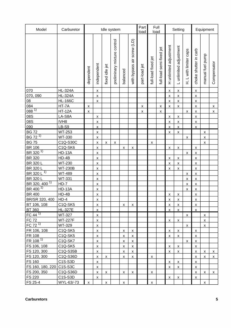
070 HL-324A x x x x070, 090 HL-324A x x x x08 HL-166C x x x x084 HT-7A x x x x x x x088 1) HT-12A x x x x x x08S LA-S8A x x x x08S IVH8 x x x x090 LB-S9 x x x xBG 72 WT-253 x x x xBG 72 1) WT-330 x x xBG 75 C1Q-S30C x x x x xBR 106 C1Q-SK6 x x x x x xBR 320 1) HD-13A x x xBR 320 HD-4B x x x xBR 320 L WT-230 x x x xBR 320 L WT-230B x x x xBR 320 L 1) WT-489 x x xBR 320 L WT-331 x x xBR 320, 400 1) HD-7 x x xBR 400 1) HD-13A x x xBR 400 HD-4B x x x xBR/SR 320, 400 HD-4 x x x xBT 106, 108 C1Q-SK5 x x x x x xBT 360 HL-327E x x x xFC 44 1) WT-327 x x xFC 72 WT-227F x x x xFC 72 1) WT-329 x x xFR 106, 108 C1Q-SK5 x x x x x xFR 108 C1Q-SK5 x x x x x xFR 108 1) C1Q-SK7 x x x x xFS 106, 108 C1Q-SK5 x x x x x xFS 120, 300 C1Q-S35B x x x x x x x xFS 120, 300 C1Q-S36D x x x x x x x xFS 160 C1S-S3D x x x xFS 160, 180, 220 C1S-S3C x x x xFS 200, 350 C1Q-S36D x x x x x x x xFS 220 C1S-S3D x x x xFS 25-4 WYL-63/-73 x x x x x
Carburetors 5
Model Carburetor Idle system Partload
Fullload Setting Equipment
depe
nden
t
inde
pend
ent
fixed
idle
jet
prel
imin
ary
mix
ture
cont
rol
bala
nced
with
bypa
ssai
rsc
rew
(LD
)
part
-load
jet
full-
load
fixed
jet
full-
load
sem
i-fix
edje
t
Hun
limite
dad
just
men
t
Lun
limite
dad
just
men
t
H,L
with
limite
rca
ps
chok
esh
utte
rin
carb
man
ualf
uelp
ump
Com
pens
ator
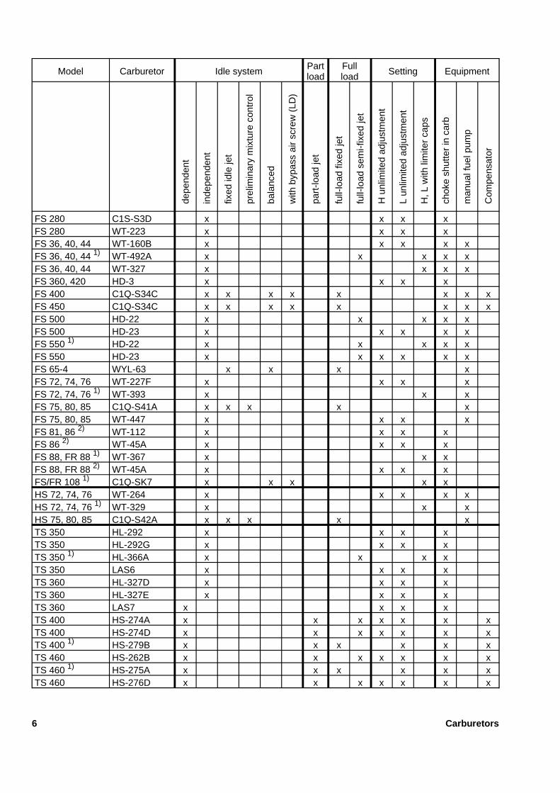
FS 280 C1S-S3D x x x xFS 280 WT-223 x x x xFS 36, 40, 44 WT-160B x x x x xFS 36, 40, 44 1) WT-492A x x x x xFS 36, 40, 44 WT-327 x x x xFS 360, 420 HD-3 x x x xFS 400 C1Q-S34C x x x x x x x xFS 450 C1Q-S34C x x x x x x x xFS 500 HD-22 x x x x xFS 500 HD-23 x x x x xFS 550 1) HD-22 x x x x xFS 550 HD-23 x x x x x xFS 65-4 WYL-63 x x x xFS 72, 74, 76 WT-227F x x x xFS 72, 74, 76 1) WT-393 x x xFS 75, 80, 85 C1Q-S41A x x x x xFS 75, 80, 85 WT-447 x x x xFS 81, 86 2) WT-112 x x x xFS 86 2) WT-45A x x x xFS 88, FR 88 1) WT-367 x x xFS 88, FR 88 2) WT-45A x x x xFS/FR 108 1) C1Q-SK7 x x x x xHS 72, 74, 76 WT-264 x x x x xHS 72, 74, 76 1) WT-329 x x xHS 75, 80, 85 C1Q-S42A x x x x xTS 350 HL-292 x x x xTS 350 HL-292G x x x xTS 350 1) HL-366A x x x xTS 350 LAS6 x x x xTS 360 HL-327D x x x xTS 360 HL-327E x x x xTS 360 LAS7 x x x xTS 400 HS-274A x x x x x x xTS 400 HS-274D x x x x x x xTS 400 1) HS-279B x x x x x xTS 460 HS-262B x x x x x x xTS 460 1) HS-275A x x x x x xTS 460 HS-276D x x x x x x x
6 Carburetors
Model Carburetor Idle system Partload
Fullload Setting Equipment
depe
nden
t
inde
pend
ent
fixed
idle
jet
prel
imin
ary
mix
ture
cont
rol
bala
nced
with
bypa
ssai
rsc
rew
(LD
)
part
-load
jet
full-
load
fixed
jet
full-
load
sem
i-fix
edje
t
Hun
limite
dad
just
men
t
Lun
limite
dad
just
men
t
H,L
with
limite
rca
ps
chok
esh
utte
rin
carb
man
ualf
uelp
ump
Com
pens
ator
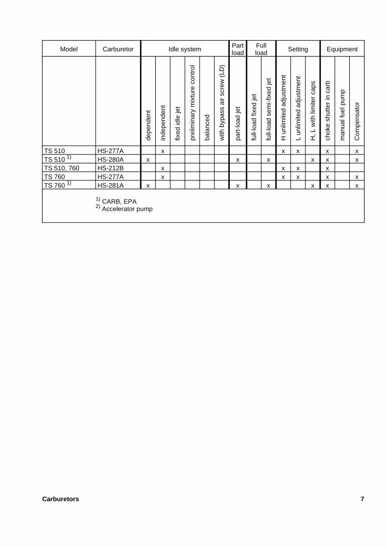
TS 510 HS-277A x x x x xTS 510 1) HS-280A x x x x x xTS 510, 760 HS-212B x x x xTS 760 HS-277A x x x x xTS 760 1) HS-281A x x x x x x
1) CARB, EPA2) Accelerator pump
Carburetors 7
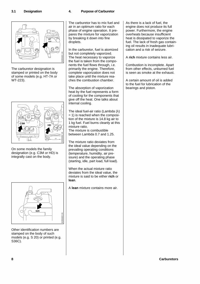
The carburetor designation isstamped or printed on the bodyof some models (e.g. HT-7A orWT-223).
On some models the familydesignation (e.g. C3M or HD) isintegrally cast on the body.
Other identification numbers arestamped on the body of suchmodels (e.g. S 20) or printed (e.g.S36C).
The carburetor has to mix fuel andair in an optimum ratio for eachphase of engine operation. It pre-pares the mixture for vaporizationby breaking it down into finedroplets.
In the carburetor, fuel is atomizedbut not completely vaporized.The heat necessary to vaporizethe fuel is taken from the compo-nents the fuel flows through, i.e.primarily the engine. Therefore,complete vaporization does nottake place until the mixture rea-ches the combustion chamber.
The absorption of vaporizationheat by the fuel represents a formof cooling for the components thatgive off the heat. One talks aboutinternal cooling.
The ideal fuel-air ratio (Lambda (λ)= 1) is reached when the composi-tion of the mixture is 14.8 kg air to1 kg fuel. Fuel burns cleanly at thismixture ratio.The mixture is combustiblebetween Lambda 0.7 and 1.25.
The mixture ratio deviates fromthe ideal value depending on theprevailing operating conditions(temperature, humidity, air pre-ssure) and the operating phase(starting, idle, part load, full load).
When the actual mixture ratiodeviates from the ideal value, themixture is said to be either rich orlean .
A lean mixture contains more air.
As there is a lack of fuel, theengine does not produce its fullpower. Furthermore, the engineoverheats because insufficientheat is dissipated to vaporize thefuel. The lack of fresh gas contain-ing oil results in inadequate lubri-cation and a risk of seizure.
A rich mixture contains less air.
Combustion is incomplete. Apartfrom other effects, unburned fuelis seen as smoke at the exhaust.
A certain amount of oil is addedto the fuel for lubrication of thebearings and piston.
3.1 Designation 4. Purpose of Carburetor
WT223
HT 7A
915R
A00
1V
A
L HL H
C3M
VA
915R
A00
2
HD
VA
915R
A00
3
S20
8 Carburetors
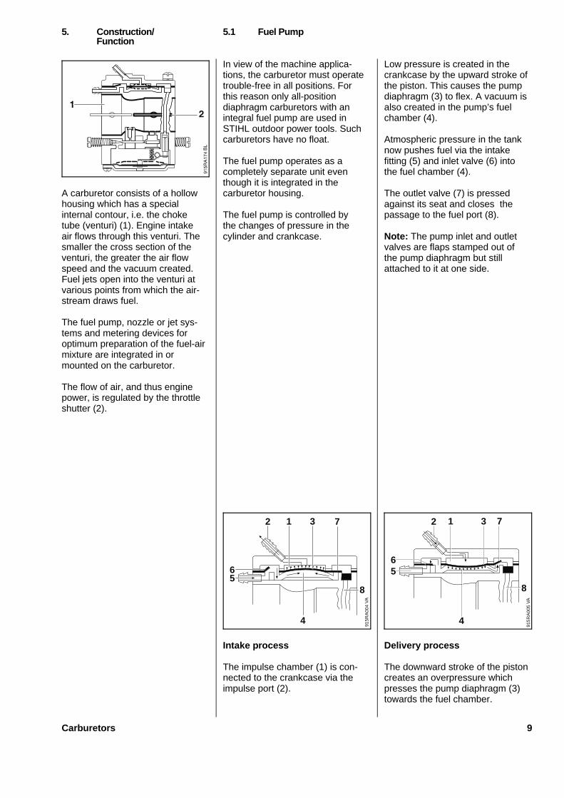
A carburetor consists of a hollowhousing which has a specialinternal contour, i.e. the choketube (venturi) (1). Engine intakeair flows through this venturi. Thesmaller the cross section of theventuri, the greater the air flowspeed and the vacuum created.Fuel jets open into the venturi atvarious points from which the air-stream draws fuel.
The fuel pump, nozzle or jet sys-tems and metering devices foroptimum preparation of the fuel-airmixture are integrated in ormounted on the carburetor.
The flow of air, and thus enginepower, is regulated by the throttleshutter (2).
In view of the machine applica-tions, the carburetor must operatetrouble-free in all positions. Forthis reason only all-positiondiaphragm carburetors with anintegral fuel pump are used inSTIHL outdoor power tools. Suchcarburetors have no float.
The fuel pump operates as acompletely separate unit eventhough it is integrated in thecarburetor housing.
The fuel pump is controlled bythe changes of pressure in thecylinder and crankcase.
Intake process
The impulse chamber (1) is con-nected to the crankcase via theimpulse port (2).
Low pressure is created in thecrankcase by the upward stroke ofthe piston. This causes the pumpdiaphragm (3) to flex. A vacuum isalso created in the pump’s fuelchamber (4).
Atmospheric pressure in the tanknow pushes fuel via the intakefitting (5) and inlet valve (6) intothe fuel chamber (4).
The outlet valve (7) is pressedagainst its seat and closes thepassage to the fuel port (8).
Note: The pump inlet and outletvalves are flaps stamped out ofthe pump diaphragm but stillattached to it at one side.
Delivery process
The downward stroke of the pistoncreates an overpressure whichpresses the pump diaphragm (3)towards the fuel chamber.
5. Construction/ 5.1 Fuel PumpFunction
VA
915R
A00
4
4
56
7
8
2 31
56
VA
915R
A00
5
4
7
8
32 1
Carburetors 9
The pump diaphragm thereforereduces the volume of the fuelchamber (4).
Inlet valve (6) is now pressedagainst its seat and closes thepassage to the intake fitting (5).The outlet valve (7) is lifted off itsseat and allows a certain amountof fuel to flow into the fuel port (8)which leads to the carburetor inletvalve.
Note: During each complete pumpstroke an amount of fuel is deliver-ed which is equivalent to thedifference in volume between thetwo end positions of the pumpdiaphragm in the fuel chamber.
On machines with a fuel tankmounted lower than the carburetorit is necessary to prime the carbu-retor with fuel after a prolongedout-of-service period by pulling thestarter rope a few times.
This problem can be overcomewith a manual fuel pump (seebelow).
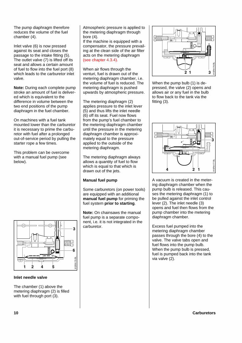
Inle t needl e valve
The chamber (1) above themetering diaphragm (2) is filledwith fuel through port (3).
Atmospheric pressure is applied tothe metering diaphragm throughbore (4).If the machine is equipped with acompensator, the pressure prevail-ing at the clean side of the air filteracts on the metering diaphragm(see chapter 4.3.4).
When air flows through theventuri, fuel is drawn out of themetering diaphragm chamber, i.e.the volume of fuel is reduced. Themetering diaphragm is pushedupwards by atmospheric pressure.
The metering diaphragm (2)applies pressure to the inlet lever(5) and thus lifts the inlet needle(6) off its seat. Fuel now flowsfrom the pump’s fuel chamber tothe metering diaphragm chamberuntil the pressure in the meteringdiaphragm chamber is approxi-mately equal to the pressureapplied to the outside of themetering diaphragm.
The metering diaphragm alwaysallows a quantity of fuel to flowwhich is equal to that which isdrawn out of the jets.
Manual fue l pump
Some carburetors (on power tools)are equipped with an additionalmanua l fue l pum p for priming thefuel system prio r to starting .
Note: On chainsaws the manualfuel pump is a separate compo-nent, i.e. it is not integrated in thecarburetor.
When the pump bulb (1) is de-pressed, the valve (2) opens andallows air or any fuel in the bulbto flow back to the tank via thefitting (3).
A vacuum is created in the meter-ing diaphragm chamber when thepump bulb is released. This cau-ses the metering diaphragm (1) tobe pulled against the inlet controllever (2). The inlet needle (3)opens and fuel then flows from thepump chamber into the meteringdiaphragm chamber.
Excess fuel pumped into themetering diaphragm chamberpasses through the bore (4) to thevalve. The valve tabs open andfuel flows into the pump bulb.When the pump bulb is pressed,fuel is pumped back into the tankvia valve (2).
10 Carburetors
Check valve
A check valve is installed in themetering diaphragm chamber ofall carburetors equipped with anadditional manual fuel pump.
When the manual fuel pump isoperated, the check valve (1) clo-ses to prevent air being suckedinto the metering diaphragm cham-ber from the venturi and the idlejet bores. During operation thecheck valve opens and allows fuelto flow to the main jet and the idlejet bores.
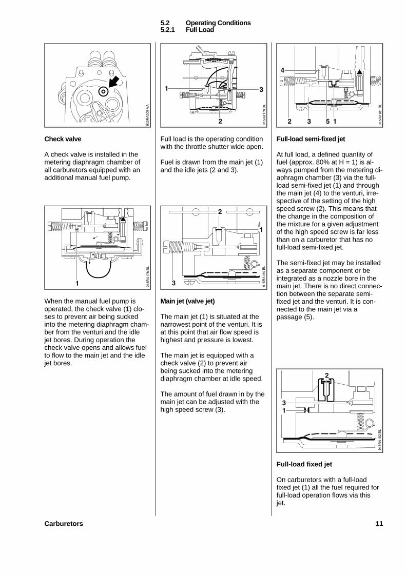
Full load is the operating conditionwith the throttle shutter wide open.
Fuel is drawn from the main jet (1)and the idle jets (2 and 3).
Main jet (valve jet)
The main jet (1) is situated at thenarrowest point of the venturi. It isat this point that air flow speed ishighest and pressure is lowest.
The main jet is equipped with acheck valve (2) to prevent airbeing sucked into the meteringdiaphragm chamber at idle speed.
The amount of fuel drawn in by themain jet can be adjusted with thehigh speed screw (3).
Full-load semi-fixed jet
At full load, a defined quantity offuel (approx. 80% at H = 1) is al-ways pumped from the metering di-aphragm chamber (3) via the full-load semi-fixed jet (1) and throughthe main jet (4) to the venturi, irre-spective of the setting of the highspeed screw (2). This means thatthe change in the composition ofthe mixture for a given adjustmentof the high speed screw is far lessthan on a carburetor that has nofull-load semi-fixed jet.
The semi-fixed jet may be installedas a separate component or beintegrated as a nozzle bore in themain jet. There is no direct connec-tion between the separate semi-fixed jet and the venturi. It is con-nected to the main jet via apassage (5).
Full-load fixed jet
On carburetors with a full-loadfixed jet (1) all the fuel required forfull-load operation flows via thisjet.
5.2 Operating Conditions5.2.1 Full Load
VA
915R
A00
9
Carburetors 11
There is no high speed screw. Thefull-load setting cannot be altered.
Like the semi-fixed jet, the full-loadfixed jet may be installed as aseparate component or be inte-grated as a nozzle bore (2) in themain jet. There is no direct connec-tion between the separate fixed jetand the venturi. It is connected tothe main jet via a passage (3).
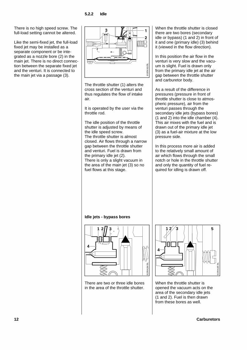
The throttle shutter (1) alters thecross section of the venturi andthus regulates the flow of intakeair.
It is operated by the user via thethrottle rod.
The idle position of the throttleshutter is adjusted by means ofthe idle speed screw.The throttle shutter is almostclosed. Air flows through a narrowgap between the throttle shutterand venturi. Fuel is drawn fromthe primary idle jet (2).There is only a slight vacuum inthe area of the main jet (3) so nofuel flows at this stage.
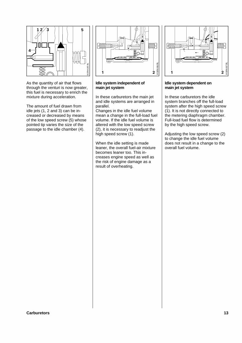
Idle jets - bypass bores
There are two or three idle boresin the area of the throttle shutter.
When the throttle shutter is closedthere are two bores (secondaryidle or bypass) (1 and 2) in front ofit and one (primary idle) (3) behindit (viewed in the flow direction).
In this position the air flow in theventuri is very slow and the vacu-um is slight. Fuel is drawn onlyfrom the primary idle jet at the airgap between the throttle shutterand carburetor body.
As a result of the difference inpressures (pressure in front ofthrottle shutter is close to atmos-pheric pressure), air from theventuri passes through thesecondary idle jets (bypass bores)(1 and 2) into the idle chamber (4).This air mixes with the fuel and isdrawn out of the primary idle jet(3) as a fuel-air mixture at the lowpressure side.
In this process more air is addedto the relatively small amount ofair which flows through the smallnotch or hole in the throttle shutterand only the quantity of fuel re-quired for idling is drawn off.
When the throttle shutter isopened the vacuum acts on thearea of the secondary idle jets(1 and 2). Fuel is then drawnfrom these bores as well.
5.2.2 Idle
915R
A18
4
4
2
BL
31
915R
A18
5
53
BL
21
4
12 Carburetors
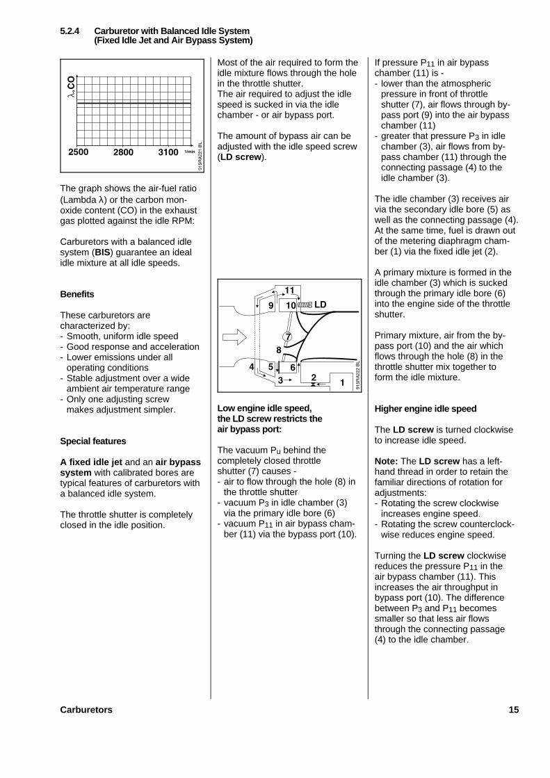
As the quantity of air that flowsthrough the venturi is now greater,this fuel is necessary to enrich themixture during acceleration.
The amount of fuel drawn fromidle jets (1, 2 and 3) can be in-creased or decreased by meansof the low speed screw (5) whosepointed tip varies the size of thepassage to the idle chamber (4).
Idle system independent ofmain jet system
In these carburetors the main jetand idle systems are arranged inparallel.Changes in the idle fuel volumemean a change in the full-load fuelvolume. If the idle fuel volume isaltered with the low speed screw(2), it is necessary to readjust thehigh speed screw (1).
When the idle setting is madeleaner, the overall fuel-air mixturebecomes leaner too. This in-creases engine speed as well asthe risk of engine damage as aresult of overheating.
Idle system dependent onmain jet system
In these carburetors the idlesystem branches off the full-loadsystem after the high speed screw(1). It is not directly connected tothe metering diaphragm chamber.Full-load fuel flow is determinedby the high speed screw.
Adjusting the low speed screw (2)to change the idle fuel volumedoes not result in a change to theoverall fuel volume.
915R
A18
5
53
BL
21
4
Carburetors 13

Idle
In the idle positon, the throttleshutter is situated between the2nd secondary idle jet (5) and theprimary idle jet (6).
The pressure in front of the throttleshutter is close to atmosphericpressure, while the vacuumcreated by the engine prevailsbehind the throttle shutter.Vacuum acts on the idle chamber(3) via the primary idle jet (6). As aresult of the pressure differential,air flows from the venturi throughthe secondary idle jets (4 and 5)into the idle chamber (3).At the same time, fuel is drawnout of the metering diaphragmchamber (1) and into the idlechamber (3) via the fixed idle jet(2).A primary mixture is created inthe idle chamber (3) which issucked through the primary idlebore (6) into the area at the engineside of the throttle shutter.
The idle air is drawn through anotch or a hole in the throttleshutter and mixes with the primarymixture to form the idle mixture.
The proportion of primary mixturein the idle mixture can be adjustedwith the idle screw (7) (primarymixture control).The machine will run with thebasic setting (approx. 1 turn open).The idle mixture is made richer byopening the idle screw (7) orleaner by closing the screw.If necessary, the idle speed canbe adjusted with the idle speedscrew (LA ).
Transition from idle topart load
When the throttle shutter isopened, vacuum acts on thesecondary idle jets (4 and 5).Fuel is then drawn from all threeidle jets (4, 5 and 6).
Transition from part load tofull load
The main jet begins to deliver fuelwhen the throttle shutter hasopened about 20 degrees. Theidle and full-load system deliverthe optimum amount of fuel to suitgiven opening conditions when thethrottle shutter is opened fully.
Advantages over conventionalcarburetors
The fixed idle jet (2) limits enrich-ment for acceleration and theamount of fuel that flows via theidle system during full-load opera-tion. As a result, the setting ofthe idle screw (7) has no effectat all on the volume of fuel atfull load .
Reduced sensitivityto temperature
Carburetors with fixed idle jetsensure a much steadier idlingbehavior at low temperatures:Fuel becomes viscous at lowertemperatures.
The more viscous the fuel is, thegreater the influence the shape ofthe throttle orifice has on the flowrate.Conventional adjusting screwscreate an annular gap (1) at thethrottle orifice which can becomeblocked within a relatively shorttime.Fixed jets have a round cross sec-tion (2) at the throttle orifice whichallows a constant flow of fuel evenat low temperatures. A constantfuel flow rate is the preconditionfor a steady idling behavior.
5.2.3 Carburetor with Fixed Idle Jet and Primary Mixture Control
VA
915R
A29
2
2
1
14 Carburetors
The graph shows the air-fuel ratio(Lambda λ) or the carbon mon-oxide content (CO) in the exhaustgas plotted against the idle RPM:
Carburetors with a balanced idlesystem (BIS) guarantee an idealidle mixture at all idle speeds.
Benefits
These carburetors arecharacterized by:- Smooth, uniform idle speed- Good response and acceleration- Lower emissions under all
operating conditions- Stable adjustment over a wide
ambient air temperature range- Only one adjusting screw
makes adjustment simpler.
Special features
A fixed idle jet and an air bypasssystem with calibrated bores aretypical features of carburetors witha balanced idle system.
The throttle shutter is completelyclosed in the idle position.
Most of the air required to form theidle mixture flows through the holein the throttle shutter.The air required to adjust the idlespeed is sucked in via the idlechamber - or air bypass port.
The amount of bypass air can beadjusted with the idle speed screw(LD screw ).
Low engine idle speed,the LD screw restricts theair bypass port:
The vacuum Pu behind thecompletely closed throttleshutter (7) causes -- air to flow through the hole (8) in
the throttle shutter- vacuum P3 in idle chamber (3)
via the primary idle bore (6)- vacuum P11 in air bypass cham-
ber (11) via the bypass port (10).
If pressure P11 in air bypasschamber (11) is -- lower than the atmospheric
pressure in front of throttleshutter (7), air flows through by-pass port (9) into the air bypasschamber (11)
- greater that pressure P3 in idlechamber (3), air flows from by-pass chamber (11) through theconnecting passage (4) to theidle chamber (3).
The idle chamber (3) receives airvia the secondary idle bore (5) aswell as the connecting passage (4).At the same time, fuel is drawn outof the metering diaphragm cham-ber (1) via the fixed idle jet (2).
A primary mixture is formed in theidle chamber (3) which is suckedthrough the primary idle bore (6)into the engine side of the throttleshutter.
Primary mixture, air from the by-pass port (10) and the air whichflows through the hole (8) in thethrottle shutter mix together toform the idle mixture.
Higher engine idle speed
The LD screw is turned clockwiseto increase idle speed.
Note: The LD screw has a left-hand thread in order to retain thefamiliar directions of rotation foradjustments:- Rotating the screw clockwise
increases engine speed.- Rotating the screw counterclock-
wise reduces engine speed.
Turning the LD screw clockwisereduces the pressure P11 in theair bypass chamber (11). Thisincreases the air throughput inbypass port (10). The differencebetween P3 and P11 becomessmaller so that less air flowsthrough the connecting passage(4) to the idle chamber.
5.2.4 Carburetor with Balanced Idle System(Fixed Idle Jet and Air Bypass System)
Carburetors 15
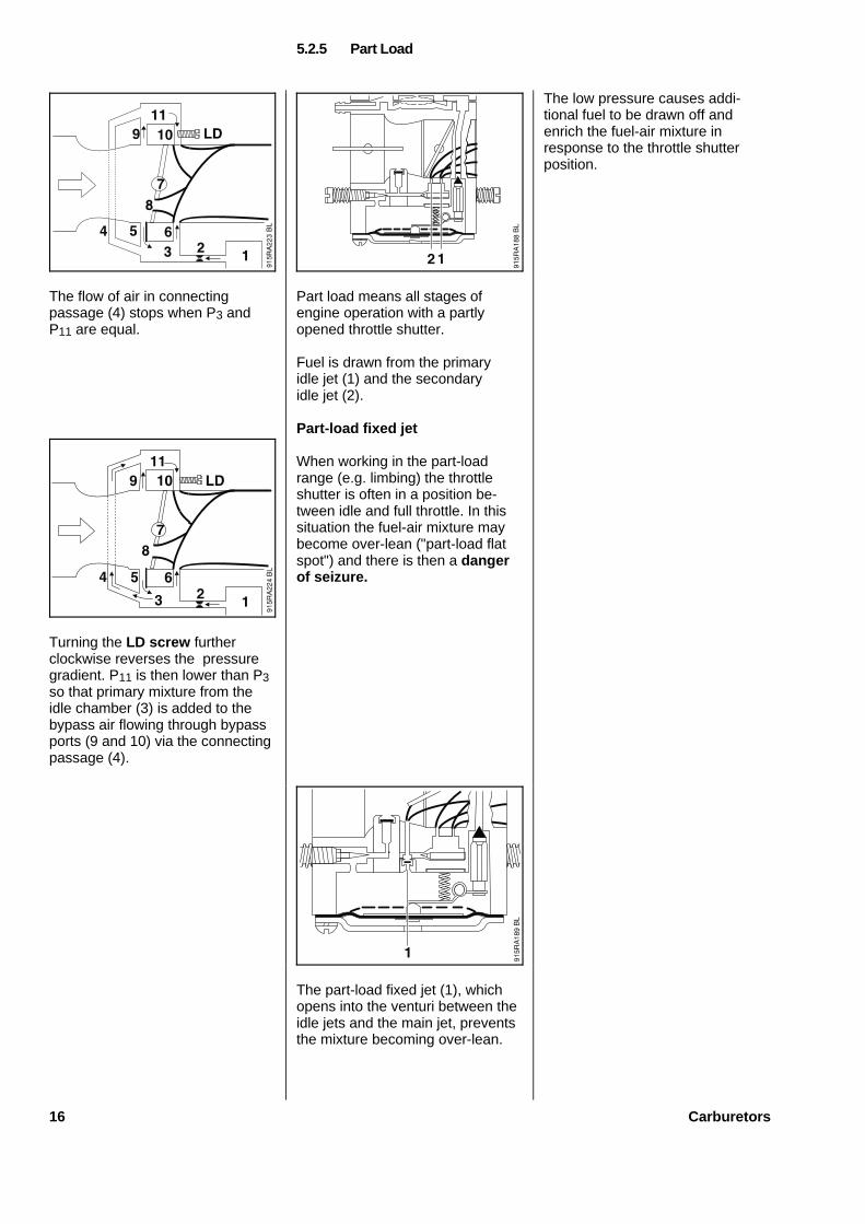
The flow of air in connectingpassage (4) stops when P3 andP11 are equal.
Turning the LD screw furtherclockwise reverses the pressuregradient. P11 is then lower than P3so that primary mixture from theidle chamber (3) is added to thebypass air flowing through bypassports (9 and 10) via the connectingpassage (4).
Part load means all stages ofengine operation with a partlyopened throttle shutter.
Fuel is drawn from the primaryidle jet (1) and the secondaryidle jet (2).
Part-load fixed jet
When working in the part-loadrange (e.g. limbing) the throttleshutter is often in a position be-tween idle and full throttle. In thissituation the fuel-air mixture maybecome over-lean ("part-load flatspot") and there is then a dangerof seizure.
The part-load fixed jet (1), whichopens into the venturi between theidle jets and the main jet, preventsthe mixture becoming over-lean.
The low pressure causes addi-tional fuel to be drawn off andenrich the fuel-air mixture inresponse to the throttle shutterposition.
5.2.5 Part Load
16 Carburetors
Hot startCompared to engine idle RPM, thespeed achieved by cranking theengine on the starter is very low.The gas flow speed and the vacu-um in the venturi are thereforelimited. Fuel and air mix poorly inthis situation.Moreover, fuel is more sluggishthan air. This means than consider-ably more air than fuel is suckedin, the mixture becomes too leanand does not burn well.
Cold startDuring a cold start the problemsdescribed for a hot start are furtheramplified.Cold components cannot transferheat to the mixture. As a result,the mixture gasifies poorly anda large proportion of the fuelcondenses on the walls of thecomponents it flows through.
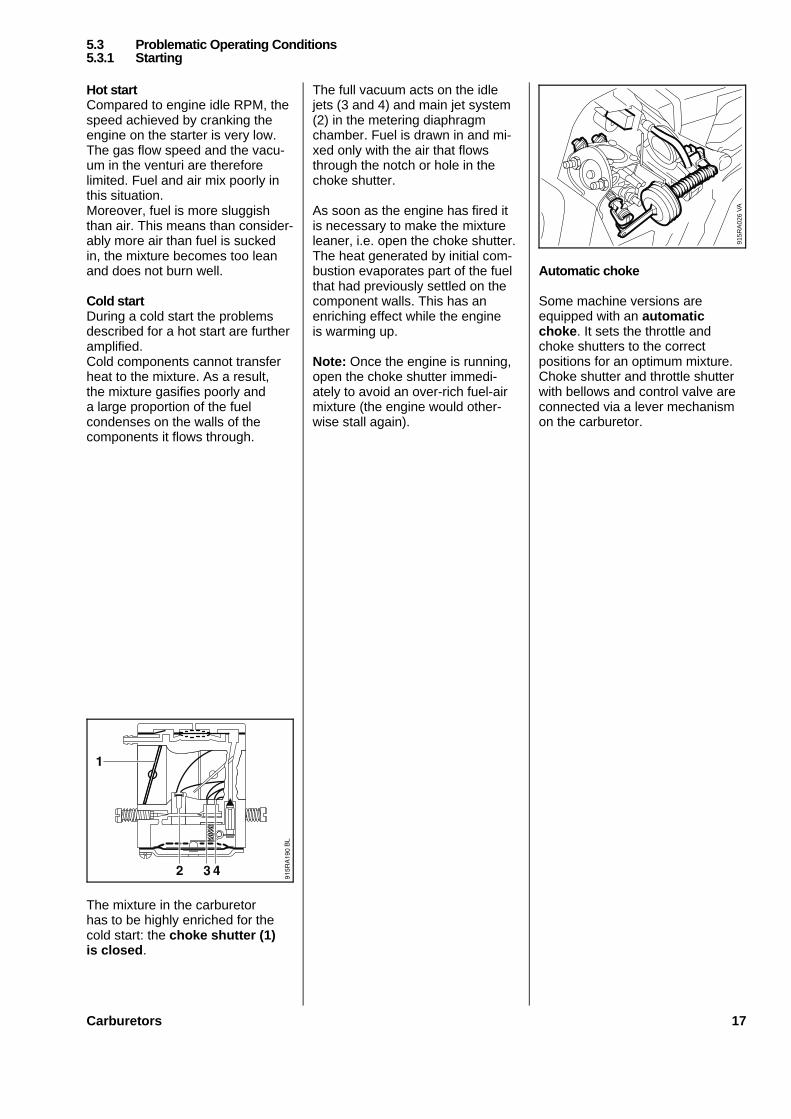
The mixture in the carburetorhas to be highly enriched for thecold start: the choke shutter (1)is closed .
The full vacuum acts on the idlejets (3 and 4) and main jet system(2) in the metering diaphragmchamber. Fuel is drawn in and mi-xed only with the air that flowsthrough the notch or hole in thechoke shutter.
As soon as the engine has fired itis necessary to make the mixtureleaner, i.e. open the choke shutter.The heat generated by initial com-bustion evaporates part of the fuelthat had previously settled on thecomponent walls. This has anenriching effect while the engineis warming up.
Note: Once the engine is running,open the choke shutter immedi-ately to avoid an over-rich fuel-airmixture (the engine would other-wise stall again).
Automatic choke
Some machine versions areequipped with an automaticchoke . It sets the throttle andchoke shutters to the correctpositions for an optimum mixture.Choke shutter and throttle shutterwith bellows and control valve areconnected via a lever mechanismon the carburetor.
5.3 Problematic Operating Conditions5.3.1 Starting
VA
915R
A02
6
Carburetors 17
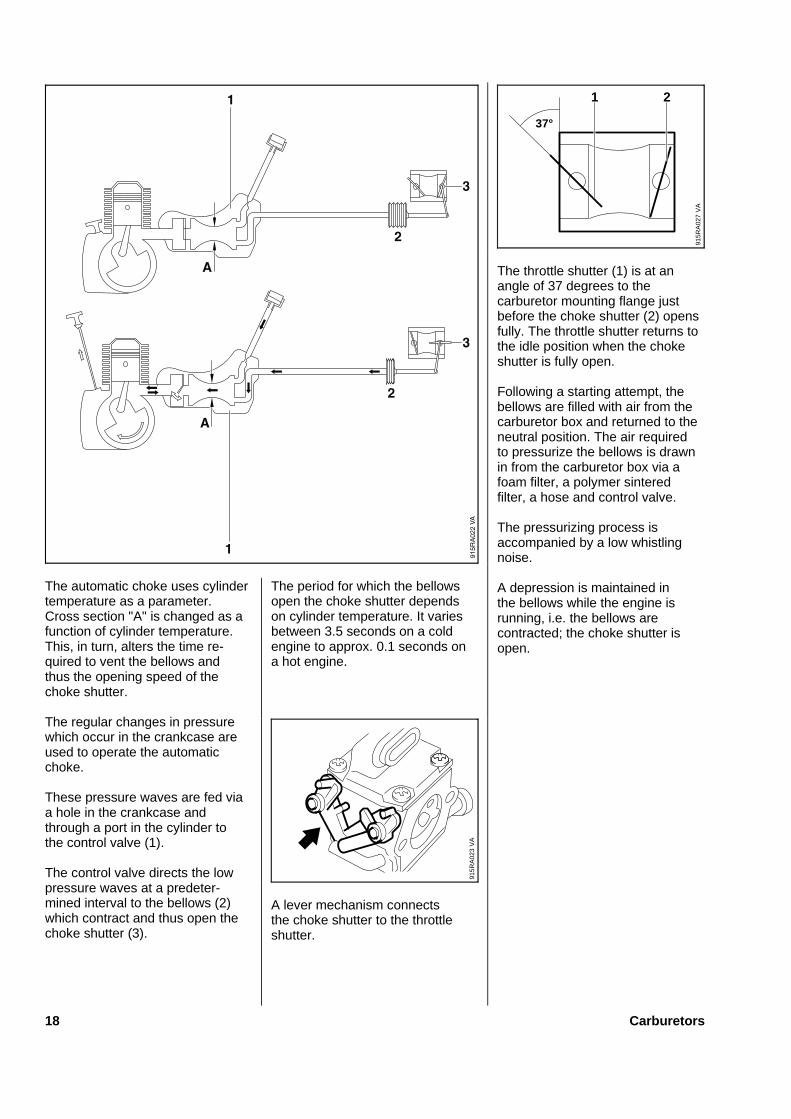
The automatic choke uses cylindertemperature as a parameter.Cross section "A" is changed as afunction of cylinder temperature.This, in turn, alters the time re-quired to vent the bellows andthus the opening speed of thechoke shutter.
The regular changes in pressurewhich occur in the crankcase areused to operate the automaticchoke.
These pressure waves are fed viaa hole in the crankcase andthrough a port in the cylinder tothe control valve (1).
The control valve directs the lowpressure waves at a predeter-mined interval to the bellows (2)which contract and thus open thechoke shutter (3).
The period for which the bellowsopen the choke shutter dependson cylinder temperature. It variesbetween 3.5 seconds on a coldengine to approx. 0.1 seconds ona hot engine.
A lever mechanism connectsthe choke shutter to the throttleshutter.
The throttle shutter (1) is at anangle of 37 degrees to thecarburetor mounting flange justbefore the choke shutter (2) opensfully. The throttle shutter returns tothe idle position when the chokeshutter is fully open.
Following a starting attempt, thebellows are filled with air from thecarburetor box and returned to theneutral position. The air requiredto pressurize the bellows is drawnin from the carburetor box via afoam filter, a polymer sinteredfilter, a hose and control valve.
The pressurizing process isaccompanied by a low whistlingnoise.
A depression is maintained inthe bellows while the engine isrunning, i.e. the bellows arecontracted; the choke shutter isopen.
VA
915R
A02
3
VA
915R
A02
7
37°
1 2
18 Carburetors
Icing can occur in the area of theintake if humidity is high and tem-peratures are below + 10°C (50°F).
Cause:Air can absorb a certain amount ofmoisture. The higher the air tem-perature the greater its capacity toabsorb moisture.
If the engine draws in damp coldair, pressure and temperaturedrop and so does the ability to ab-sorb moisture. Moisture conden-ses on the intake passages, espe-cially in the carburetor. Thisresults in ice forming, which blocksthe jets and causes engine run-ning problems.
If the air filter is dirty, the air flowrate and pressure in the venturi(Pi) drop.
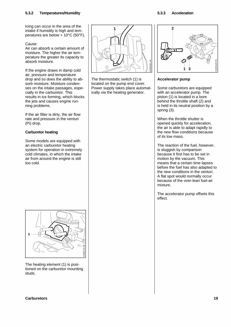
Carburetor heating
Some models are equipped withan electric carburetor heatingsystem for operation in extremelycold climates, in which the intakeair from around the engine is stilltoo cold.
The heating element (1) is posi-tioned on the carburetor mountingstuds.
The thermostatic switch (1) islocated on the pump end cover.Power supply takes place automat-ically via the heating generator.
Accelerator pump
Some carburetors are equippedwith an accelerator pump. Thepiston (1) is located in a borebehind the throttle shaft (2) andis held in its neutral position by aspring (3).
When the throttle shutter isopened quickly for acceleration,the air is able to adapt rapidly tothe new flow conditions becauseof its low mass.
The reaction of the fuel, however,is sluggish by comparisonbecause it first has to be set inmotion by the vacuum. Thismeans that a certain time lapsesbefore the fuel has also adapted tothe new conditions in the venturi.A flat spot would normally occurbecause of the over-lean fuel-airmixture.
The accelerator pump offsets thiseffect.
5.3.2 Temperatures/Humidity 5.3.3 Acceleration
VA
915R
A29
1
1
VA
915R
A02
9
3
2
1
Carburetors 19
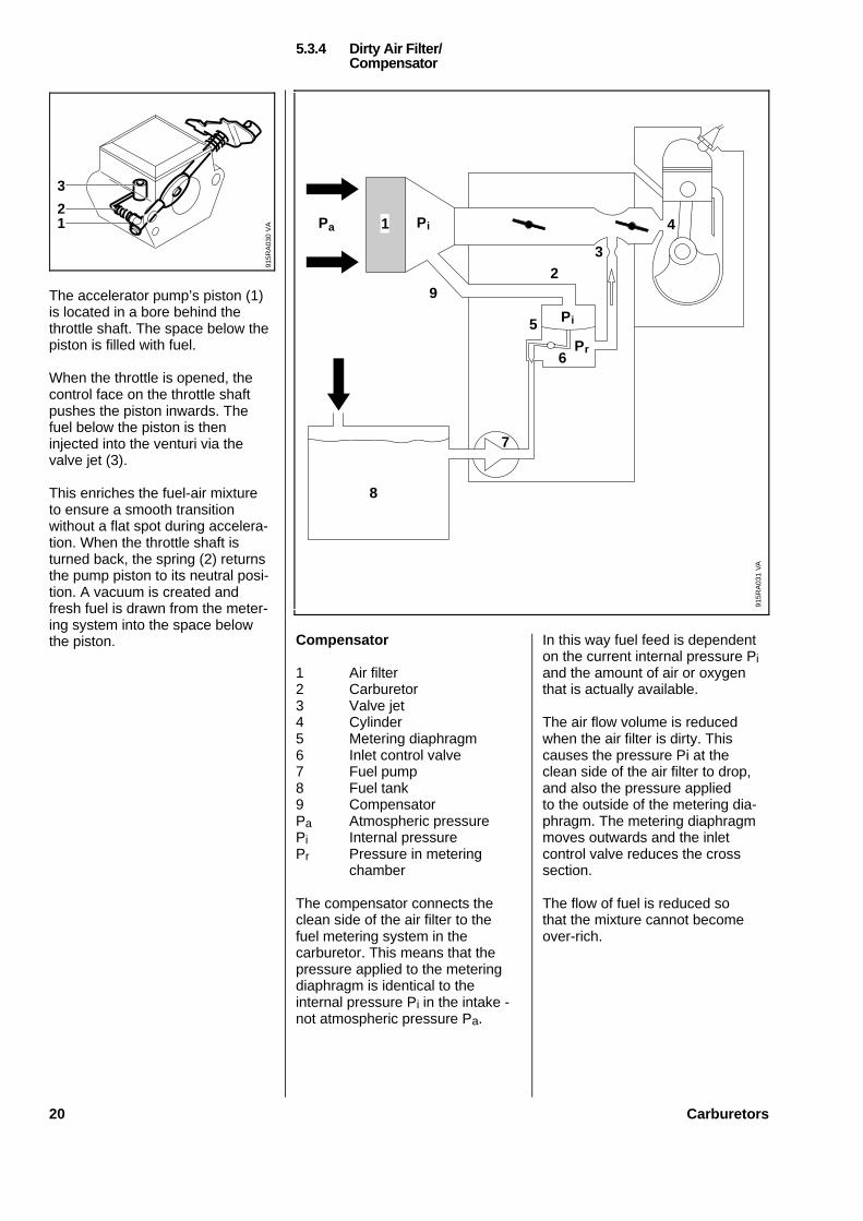
The accelerator pump’s piston (1)is located in a bore behind thethrottle shaft. The space below thepiston is filled with fuel.
When the throttle is opened, thecontrol face on the throttle shaftpushes the piston inwards. Thefuel below the piston is theninjected into the venturi via thevalve jet (3).
This enriches the fuel-air mixtureto ensure a smooth transitionwithout a flat spot during accelera-tion. When the throttle shaft isturned back, the spring (2) returnsthe pump piston to its neutral posi-tion. A vacuum is created andfresh fuel is drawn from the meter-ing system into the space belowthe piston. Compensator
1 Air filter2 Carburetor3 Valve jet4 Cylinder5 Metering diaphragm6 Inlet control valve7 Fuel pump8 Fuel tank9 CompensatorPa Atmospheric pressurePi Internal pressurePr Pressure in metering
chamber
The compensator connects theclean side of the air filter to thefuel metering system in thecarburetor. This means that thepressure applied to the meteringdiaphragm is identical to theinternal pressure Pi in the intake -not atmospheric pressure Pa.
In this way fuel feed is dependenton the current internal pressure Piand the amount of air or oxygenthat is actually available.
The air flow volume is reducedwhen the air filter is dirty. Thiscauses the pressure Pi at theclean side of the air filter to drop,and also the pressure appliedto the outside of the metering dia-phragm. The metering diaphragmmoves outwards and the inletcontrol valve reduces the crosssection.
The flow of fuel is reduced sothat the mixture cannot becomeover-rich.
5.3.4 Dirty Air Filter/Compensator
VA
915R
A03
0
3
21
7
3
1
92
5
6
8
4P
915R
A03
1V
A
a Pi
Pi
Pr
20 Carburetors
A carburetor equipped with a com-pensator therefore keeps the fuelcontent in the mixture constant atall times, irrespective of air filtercontamination.It is no longer necessary to alterthe setting of the high speedscrew as contamination of theair filter increases.
However, engine power drops asa result of the reduction in airvolume and can only be restoredto normal by cleaning the air filter.There is no need for any furtheradjustment after cleaning.
A conversion from a HD (textile)filter to a standard (wire mesh)filter or vice versa does not neces-sitate readjustment of the mixtureeither.
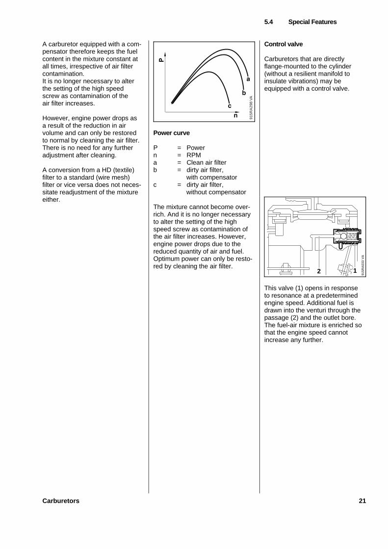
Power curve
P = Powern = RPMa = Clean air filterb = dirty air filter,
with compensatorc = dirty air filter,
without compensator
The mixture cannot become over-rich. And it is no longer necessaryto alter the setting of the highspeed screw as contamination ofthe air filter increases. However,engine power drops due to thereduced quantity of air and fuel.Optimum power can only be resto-red by cleaning the air filter.
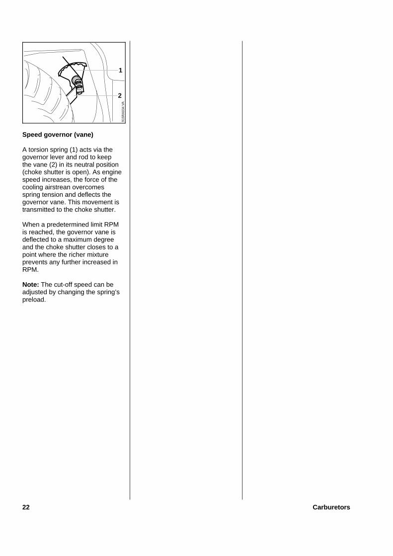
Control valve
Carburetors that are directlyflange-mounted to the cylinder(without a resilient manifold toinsulate vibrations) may beequipped with a control valve.
This valve (1) opens in responseto resonance at a predeterminedengine speed. Additional fuel isdrawn into the venturi through thepassage (2) and the outlet bore.The fuel-air mixture is enriched sothat the engine speed cannotincrease any further.
5.4 Special Features
915R
A29
8 V
A
VA
915R
A03
3
2 1
Carburetors 21
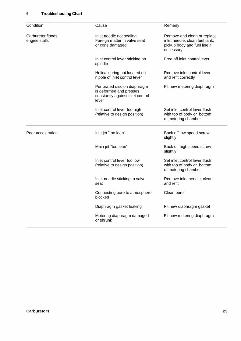
Speed governor (vane)
A torsion spring (1) acts via thegovernor lever and rod to keepthe vane (2) in its neutral position(choke shutter is open). As enginespeed increases, the force of thecooling airstrean overcomesspring tension and deflects thegovernor vane. This movement istransmitted to the choke shutter.
When a predetermined limit RPMis reached, the governor vane isdeflected to a maximum degreeand the choke shutter closes to apoint where the richer mixtureprevents any further increased inRPM.
Note: The cut-off speed can beadjusted by changing the spring’spreload.
VA
915R
A03
4
1
2
22 Carburetors
Condition Cause Remedy
Carburetor floods; Inlet needle not sealing. Remove and clean or replaceengine stalls Foreign matter in valve seat inlet needle, clean fuel tank,
or cone damaged pickup body and fuel line ifnecessary
Inlet control lever sticking on Free off inlet control leverspindle
Helical spring not located on Remove inlet control levernipple of inlet control lever and refit correctly
Perforated disc on diaphragm Fit new metering diaphragmis deformed and pressesconstantly against inlet controllever
Inlet control lever too high Set inlet control lever flush(relative to design position) with top of body or bottom
of metering chamber
Poor acceleration Idle jet "too lean" Back off low speed screwslightly
Main jet "too lean" Back off high speed screwslightly
Inlet control lever too low Set inlet control lever flush(relative to design position) with top of body or bottom
of metering chamber
Inlet needle sticking to valve Remove inlet needle, cleanseat and refit
Connecting bore to atmosphere Clean boreblocked
Diaphragm gasket leaking Fit new diaphragm gasket
Metering diaphragm damaged Fit new metering diaphragmor shrunk
6. Troubleshooting Chart
Carburetors 23
Condition Cause Remedy
Engine will not idle, Throttle shutter opened too wide Reset idle speed screwidle speed too high by idle speed screw correctly
Idle speed screw (LD) opened Adjust idle speed screw correctlytoo far
Idle speed screw (LA) opened Adjust idle speed screw correctlytoo far
Machine leaking Locate and repair leak
Engine stalls at idle speed Idle jet bores or ports Clean jet bores and portsblocked with compressed air
Idle jet "too rich" Screw down low speed screwslightly
Setting of idle speed Set idle speed screwscrew incorrect correctly- throttle shutter completelyclosed
Setting of idle speed Set idle speed screwscrew (LD) incorrect correctly
Small plastic plate in valve Clean or renew valve jetjet does not close
Engine speed drops quickly Air filter plugged Clean air filterunder load - low power
Tank vent faulty Clean or replace tank ventif necessary
Leak in fuel line between Seal or renew connectionstank and fuel pump and fuel line
Pump diaphragm damaged Fit new pump diaphragmor fatigued
Main jet bores or ports Clean bores and portsblocked
Fuel pickup body dirty Clean pickup body, fit newfilter
Fuel strainers dirty Clean fuel strainers
24 Carburetors
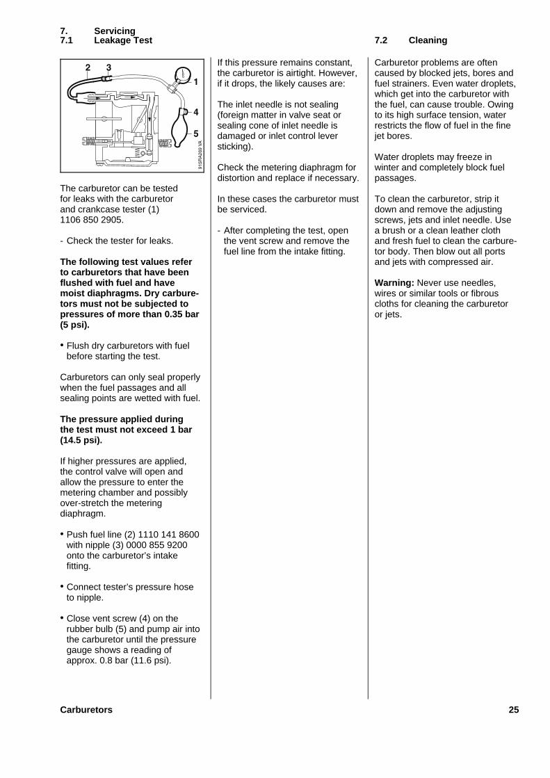
The carburetor can be testedfor leaks with the carburetorand crankcase tester (1)1106 850 2905.
- Check the tester for leaks.
The following test values referto carburetors that have beenflushed with fuel and havemoist diaphragms. Dry carbure-tors must not be subjected topressures of more than 0.35 bar(5 psi).
• Flush dry carburetors with fuelbefore starting the test.
Carburetors can only seal properlywhen the fuel passages and allsealing points are wetted with fuel.
The pressure applied duringthe test must not exceed 1 bar(14.5 psi).
If higher pressures are applied,the control valve will open andallow the pressure to enter themetering chamber and possiblyover-stretch the meteringdiaphragm.
• Push fuel line (2) 1110 141 8600with nipple (3) 0000 855 9200onto the carburetor’s intakefitting.
• Connect tester’s pressure hoseto nipple.
• Close vent screw (4) on therubber bulb (5) and pump air intothe carburetor until the pressuregauge shows a reading ofapprox. 0.8 bar (11.6 psi).
If this pressure remains constant,the carburetor is airtight. However,if it drops, the likely causes are:
The inlet needle is not sealing(foreign matter in valve seat orsealing cone of inlet needle isdamaged or inlet control leversticking).
Check the metering diaphragm fordistortion and replace if necessary.
In these cases the carburetor mustbe serviced.
- After completing the test, openthe vent screw and remove thefuel line from the intake fitting.
Carburetor problems are oftencaused by blocked jets, bores andfuel strainers. Even water droplets,which get into the carburetor withthe fuel, can cause trouble. Owingto its high surface tension, waterrestricts the flow of fuel in the finejet bores.
Water droplets may freeze inwinter and completely block fuelpassages.
To clean the carburetor, strip itdown and remove the adjustingscrews, jets and inlet needle. Usea brush or a clean leather clothand fresh fuel to clean the carbure-tor body. Then blow out all portsand jets with compressed air.
Warning: Never use needles,wires or similar tools or fibrouscloths for cleaning the carburetoror jets.
7. Servicing7.1 Leakage Test 7.2 Cleaning
Carburetors 25
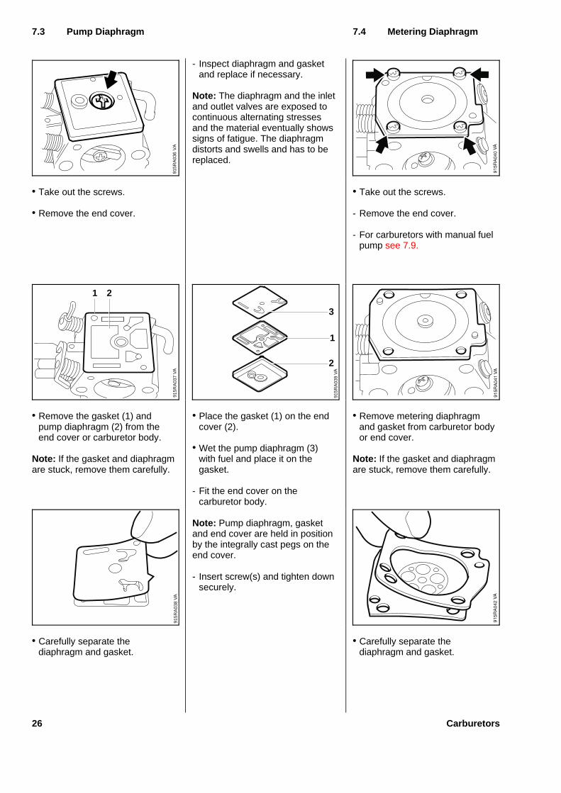
• Take out the screws.
• Remove the end cover.
• Remove the gasket (1) andpump diaphragm (2) from theend cover or carburetor body.
Note: If the gasket and diaphragmare stuck, remove them carefully.
• Carefully separate thediaphragm and gasket.
- Inspect diaphragm and gasketand replace if necessary.
Note: The diaphragm and the inletand outlet valves are exposed tocontinuous alternating stressesand the material eventually showssigns of fatigue. The diaphragmdistorts and swells and has to bereplaced.
• Place the gasket (1) on the endcover (2).
• Wet the pump diaphragm (3)with fuel and place it on thegasket.
- Fit the end cover on thecarburetor body.
Note: Pump diaphragm, gasketand end cover are held in positionby the integrally cast pegs on theend cover.
- Insert screw(s) and tighten downsecurely.
• Take out the screws.
- Remove the end cover.
- For carburetors with manual fuelpump see 7.9.
• Remove metering diaphragmand gasket from carburetor bodyor end cover.
Note: If the gasket and diaphragmare stuck, remove them carefully.
• Carefully separate thediaphragm and gasket.
7.3 Pump Diaphragm 7.4 Meterin g Diaphragm
VA
915R
A03
9
3
1
2
VA
915R
A03
6V
A91
5RA
037
21
VA
915R
A03
8
26 Carburetors
- Inspect diaphragm and gasketand replace if necessary.
Note: The diaphragm is exposedto continuous alternating stressesand the material eventually showssigns of fatigue. The diaphragmdistorts and swells and has to bereplaced.
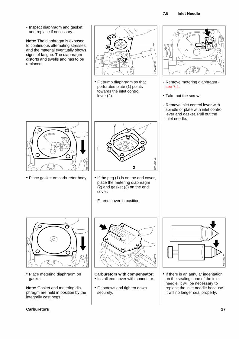
• Place gasket on carburetor body.
• Place metering diaphragm ongasket.
Note: Gasket and metering dia-phragm are held in position by theintegrally cast pegs.
• Fit pump diaphragm so thatperforated plate (1) pointstowards the inlet controllever (2).
• If the peg (1) is on the end cover,place the metering diaphragm(2) and gasket (3) on the endcover.
- Fit end cover in position.
Carburetor s wit h compensator:• Install end cover with connector.
• Fit screws and tighten downsecurely.
- Remove metering diaphragm -see 7.4.
• Take out the screw.
- Remove inlet control lever withspindle or plate with inlet controllever and gasket. Pull out theinlet needle.
• If there is an annular indentationon the sealing cone of the inletneedle, it will be necessary toreplace the inlet needle becauseit will no longer seal properly.
7.5 Inle t Needle
VA
915R
A04
5
1
2
VA
915R
A04
8
VA
915R
A04
6
2
1
3
VA
915R
A04
7
VA
915R
A04
3V
A91
5RA
044
Carburetors 27
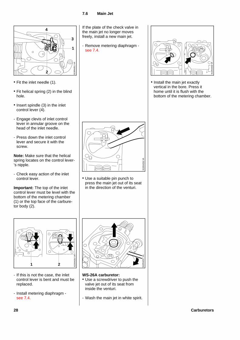
• Fit the inlet needle (1).
• Fit helical spring (2) in the blindhole.
• Insert spindle (3) in the inletcontrol lever (4).
- Engage clevis of inlet controllever in annular groove on thehead of the inlet needle.
- Press down the inlet controllever and secure it with thescrew.
Note: Make sure that the helicalspring locates on the control lever-’s nipple.
- Check easy action of the inletcontrol lever.
Important : The top of the inletcontrol lever must be level with thebottom of the metering chamber(1) or the top face of the carbure-tor body (2).
- If this is not the case, the inletcontrol lever is bent and must bereplaced.
- Install metering diaphragm -see 7.4.
If the plate of the check valve inthe main jet no longer movesfreely, install a new main jet.
- Remove metering diaphragm -see 7.4.
• Use a suitable pin punch topress the main jet out of its seatin the direction of the venturi.
WS-26A carburetor:• Use a screwdriver to push the
valve jet out of its seat frominside the venturi.
- Wash the main jet in white spirit.
• Install the main jet exactlyvertical in the bore. Press ithome until it is flush with thebottom of the metering chamber.
7.6 Main Jet
VA
915R
A05
8
VA
915R
A05
6
VA
915R
A05
4
1 2
VA
915R
A05
7
VA
915R
A05
12
1
3
4
28 Carburetors
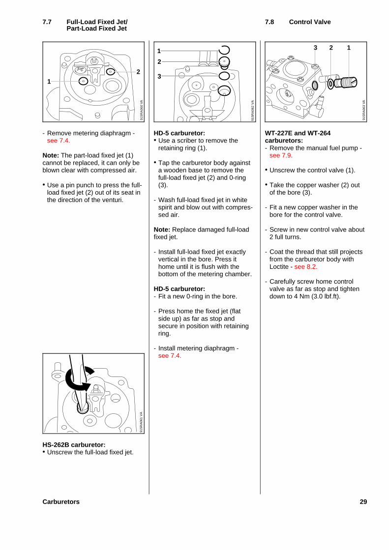
- Remove metering diaphragm -see 7.4.
Note: The part-load fixed jet (1)cannot be replaced, it can only beblown clear with compressed air.
• Use a pin punch to press the full-load fixed jet (2) out of its seat inthe direction of the venturi.
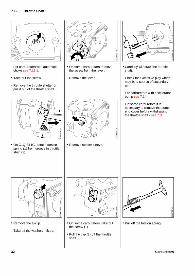
HS-262B carburetor:• Unscrew the full-load fixed jet.
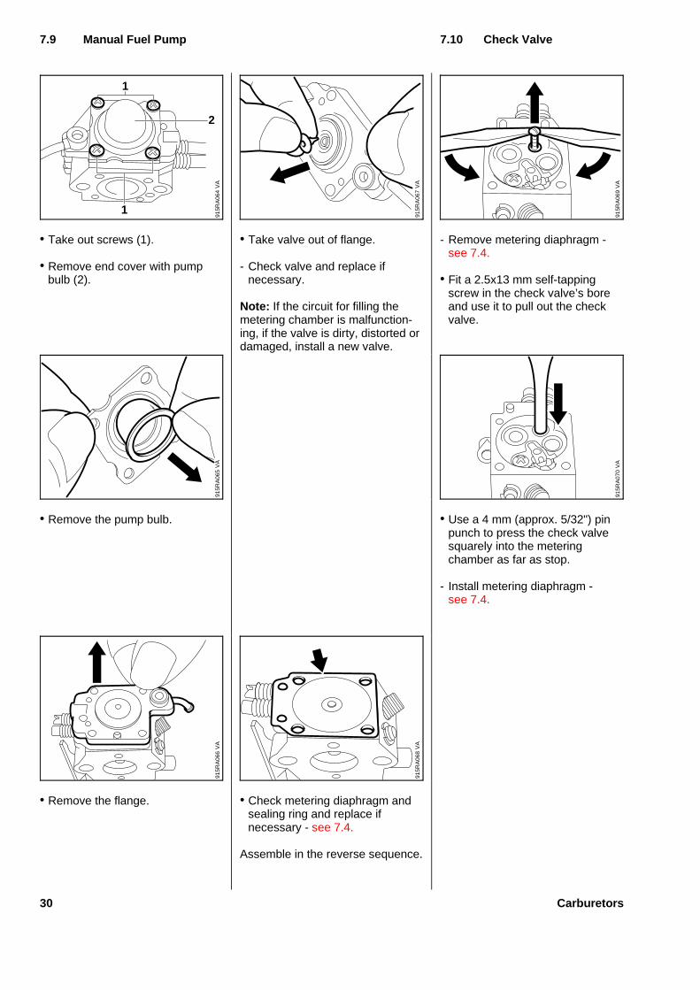
HD-5 carburetor:• Use a scriber to remove the
retaining ring (1).
• Tap the carburetor body againsta wooden base to remove thefull-load fixed jet (2) and 0-ring(3).
- Wash full-load fixed jet in whitespirit and blow out with compres-sed air.
Note: Replace damaged full-loadfixed jet.
- Install full-load fixed jet exactlyvertical in the bore. Press ithome until it is flush with thebottom of the metering chamber.
HD-5 carburetor:- Fit a new 0-ring in the bore.
- Press home the fixed jet (flatside up) as far as stop andsecure in position with retainingring.
- Install metering diaphragm -see 7.4.
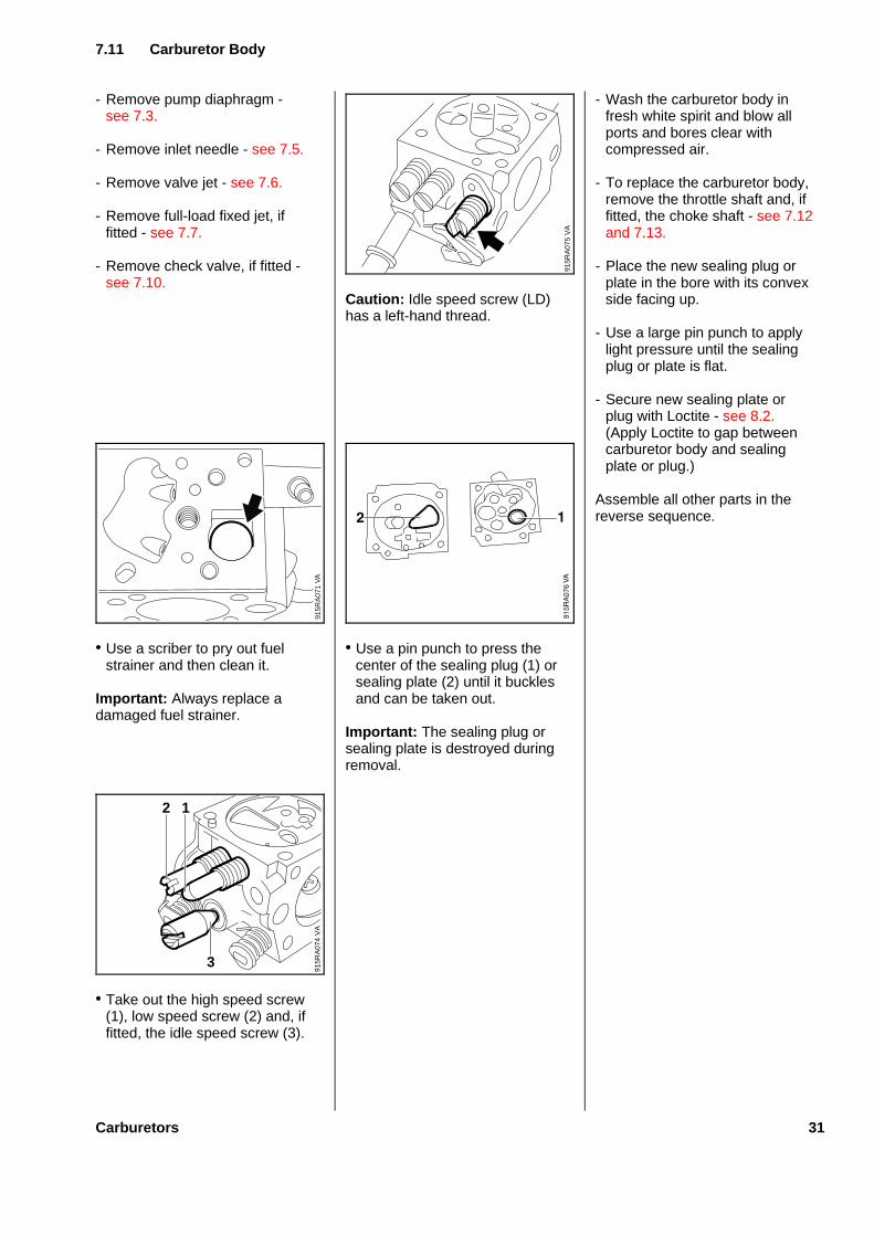
WT-227E and WT-264carburetors:- Remove the manual fuel pump -
see 7.9.
• Unscrew the control valve (1).
• Take the copper washer (2) outof the bore (3).
- Fit a new copper washer in thebore for the control valve.
- Screw in new control valve about2 full turns.
- Coat the thread that still projectsfrom the carburetor body withLoctite - see 8.2.
- Carefully screw home controlvalve as far as stop and tightendown to 4 Nm (3.0 lbf.ft).
7.7 Full-Loa d Fixed Jet/ 7.8 Contro l ValvePart-Loa d Fixed Jet
VA
915R
A06
0
2
1
VA
915R
A06
2
3
2
1
VA
915R
A06
3
123
VA
915R
A06
1
Carburetors 29
• Take out screws (1).
• Remove end cover with pumpbulb (2).
• Remove the pump bulb.
• Remove the flange.
• Take valve out of flange.
- Check valve and replace ifnecessary.
Note: If the circuit for filling themetering chamber is malfunction-ing, if the valve is dirty, distorted ordamaged, install a new valve.
• Check metering diaphragm andsealing ring and replace ifnecessary - see 7.4.
Assemble in the reverse sequence.
- Remove metering diaphragm -see 7.4.
• Fit a 2.5x13 mm self-tappingscrew in the check valve’s boreand use it to pull out the checkvalve.
• Use a 4 mm (approx. 5/32") pinpunch to press the check valvesquarely into the meteringchamber as far as stop.
- Install metering diaphragm -see 7.4.
7.9 Manual Fuel Pump 7.10 Check Valve
VA
915R
A06
4
2
1
1
VA
915R
A06
7
VA
915R
A06
9
VA
915R
A06
5
VA
915R
A06
8
VA
915R
A07
0
VA
915R
A06
6
30 Carburetors
- Remove pump diaphragm -see 7.3.
- Remove inlet needle - see 7.5.
- Remove valve jet - see 7.6.
- Remove full-load fixed jet, iffitted - see 7.7.
- Remove check valve, if fitted -see 7.10.
• Use a scriber to pry out fuelstrainer and then clean it.
Important : Always replace adamaged fuel strainer.
• Take out the high speed screw(1), low speed screw (2) and, iffitted, the idle speed screw (3).
Caution : Idle speed screw (LD)has a left-hand thread.
• Use a pin punch to press thecenter of the sealing plug (1) orsealing plate (2) until it bucklesand can be taken out.
Important : The sealing plug orsealing plate is destroyed duringremoval.
- Wash the carburetor body infresh white spirit and blow allports and bores clear withcompressed air.
- To replace the carburetor body,remove the throttle shaft and, iffitted, the choke shaft - see 7.12and 7.13.
- Place the new sealing plug orplate in the bore with its convexside facing up.
- Use a large pin punch to applylight pressure until the sealingplug or plate is flat.
- Secure new sealing plate orplug with Loctite - see 8.2.(Apply Loctite to gap betweencarburetor body and sealingplate or plug.)
Assemble all other parts in thereverse sequence.
7.11 Carbureto r Body
VA
915R
A07
1V
A91
5RA
074
2 1
3
VA
915R
A07
5
Carburetors 31
- For carburetors with automaticchoke see 7.15.1.
• Take out the screw.
- Remove the throttle shutter orpull it out of the throttle shaft.
• On C1Q-S11G, detach torsionspring (1) from groove in throttleshaft (2).
• Remove the E-clip.
- Take off the washer, if fitted.
• On some carburetors, removethe screw from the lever.
- Remove the lever.
• Remove spacer sleeve.
• On some carburetors, take outthe screw (1).
• Pull the clip (2) off the throttleshaft.
• Carefully withdraw the throttleshaft.
- Check for excessive play whichmay be a source of secondaryair.
- For carburetors with acceleratorpump see 7.14.
- On some carburetors it isnecessary to remove the pumpend cover before withdrawingthe throttle shaft - see 7.3.
• Pull off the torsion spring.
7.12 Throttl e Shaft
VA
915R
A07
7
VA
915R
A08
0
VA
915R
A07
8
2
1V
A91
5RA
081
VA
915R
A07
9
VA
915R
A08
5
2
1
VA
915R
A08
6V
A91
5RA
087
32 Carburetors
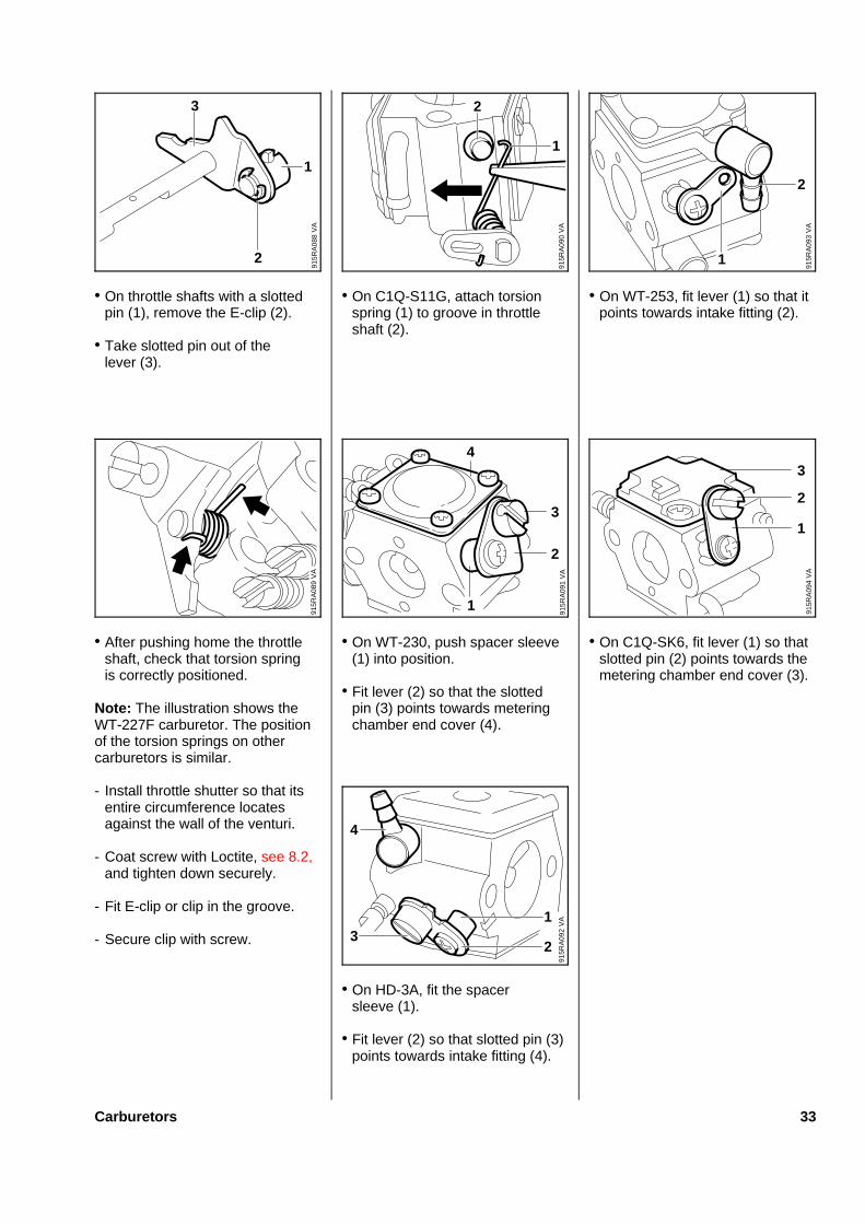
• On throttle shafts with a slottedpin (1), remove the E-clip (2).
• Take slotted pin out of thelever (3).
• After pushing home the throttleshaft, check that torsion springis correctly positioned.
Note: The illustration shows theWT-227F carburetor. The positionof the torsion springs on othercarburetors is similar.
- Install throttle shutter so that itsentire circumference locatesagainst the wall of the venturi.
- Coat screw with Loctite, see 8.2,and tighten down securely.
- Fit E-clip or clip in the groove.
- Secure clip with screw.
• On C1Q-S11G, attach torsionspring (1) to groove in throttleshaft (2).
• On WT-230, push spacer sleeve(1) into position.
• Fit lever (2) so that the slottedpin (3) points towards meteringchamber end cover (4).
• On HD-3A, fit the spacersleeve (1).
• Fit lever (2) so that slotted pin (3)points towards intake fitting (4).
• On WT-253, fit lever (1) so that itpoints towards intake fitting (2).
• On C1Q-SK6, fit lever (1) so thatslotted pin (2) points towards themetering chamber end cover (3).
VA
915R
A08
8
22
1
3
VA
915R
A09
0
2
1
VA
915R
A08
9
4
3
291
5RA
091
VA
1
VA
915R
A09
2
1
23
4
VA
915R
A09
3
2
1
VA
915R
A09
4
1
2
3
Carburetors 33
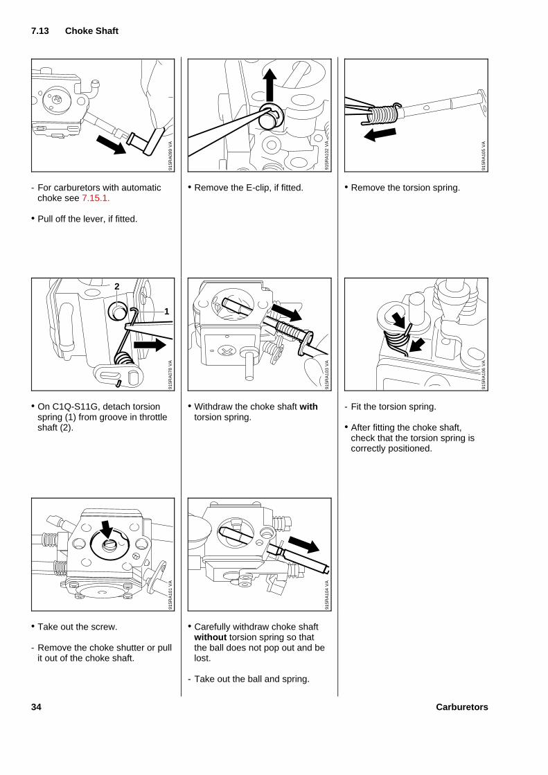
- For carburetors with automaticchoke see 7.15.1.
• Pull off the lever, if fitted.
• On C1Q-S11G, detach torsionspring (1) from groove in throttleshaft (2).
• Take out the screw.
- Remove the choke shutter or pullit out of the choke shaft.
• Remove the E-clip, if fitted.
• Withdraw the choke shaft withtorsion spring.
• Carefully withdraw choke shaftwithout torsion spring so thatthe ball does not pop out and belost.
- Take out the ball and spring.
• Remove the torsion spring.
- Fit the torsion spring.
• After fitting the choke shaft,check that the torsion spring iscorrectly positioned.
7.13 Chok e Shaft
VA
915R
A09
9V
A91
5RA
078
2
1
VA
915R
A10
1
915R
A10
2V
AV
A91
5RA
103
VA
915R
A10
4
VA
915R
A10
5V
A91
5RA
106
34 Carburetors
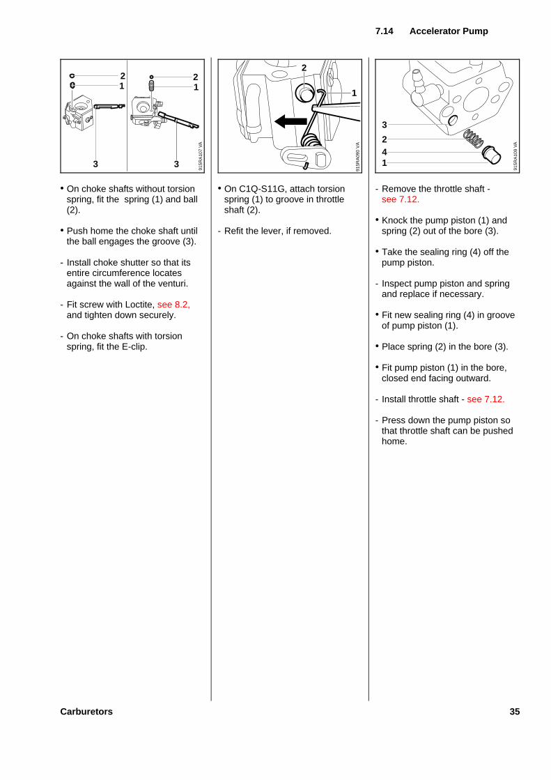
• On choke shafts without torsionspring, fit the spring (1) and ball(2).
• Push home the choke shaft untilthe ball engages the groove (3).
- Install choke shutter so that itsentire circumference locatesagainst the wall of the venturi.
- Fit screw with Loctite, see 8.2,and tighten down securely.
- On choke shafts with torsionspring, fit the E-clip.
• On C1Q-S11G, attach torsionspring (1) to groove in throttleshaft (2).
- Refit the lever, if removed.
- Remove the throttle shaft -see 7.12.
• Knock the pump piston (1) andspring (2) out of the bore (3).
• Take the sealing ring (4) off thepump piston.
- Inspect pump piston and springand replace if necessary.
• Fit new sealing ring (4) in grooveof pump piston (1).
• Place spring (2) in the bore (3).
• Fit pump piston (1) in the bore,closed end facing outward.
- Install throttle shaft - see 7.12.
- Press down the pump piston sothat throttle shaft can be pushedhome.
VA
915R
A09
0
2
1
7.14 Accelerato r Pump
3
VA
915R
A10
7
3
112 2
VA
915R
A10
9
3
241
Carburetors 35
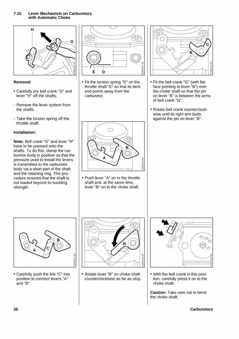
Removal:
• Carefully pry bell crank "G" andlever "H" off the shafts.
- Remove the lever system fromthe shafts.
- Take the torsion spring off thethrottle shaft.
Installation:
Note: Bell crank "G" and lever "H"have to be pressed onto theshafts. To do this, clamp the car-buretor body in position so that thepressure used to install the leversis transmitted to the carburetorbody via a short part of the shaftand the retaining ring. This pro-cedure ensures that the shaft isnot loaded beyond its bucklingstrength.
• Carefully push the link "C" intoposition to connect levers "A"and "B".
• Fit the torsion spring "D" on thethrottle shaft "E" so that its bentend points away from thecarburetor.
• Push lever "A" on to the throttleshaft and, at the same time,lever "B" on to the choke shaft.
• Rotate lever "B" on choke shaftcounterclockwise as far as stop.
• Fit the bell crank "G" (with flatface pointing to lever "B") overthe choke shaft so that the pinon lever "B" is between the armsof bell crank "G".
• Rotate bell crank counterclock-wise until its right arm buttsagainst the pin on lever "B".
• With the bell crank in this posi-tion, carefully press it on to thechoke shaft.
Caution: Take care not to bendthe choke shaft.
VA
915R
A11
0
H
G
VA
915R
A11
2
E D
VA
915R
A11
3
A
B
VA
915R
A11
1
A C
B
VA
915R
A11
4
B
7.15 Lever Mechanism on Carburetorswith Automatic Choke
VA
915R
A11
5
B
G
VA
915R
A11
6
36 Carburetors
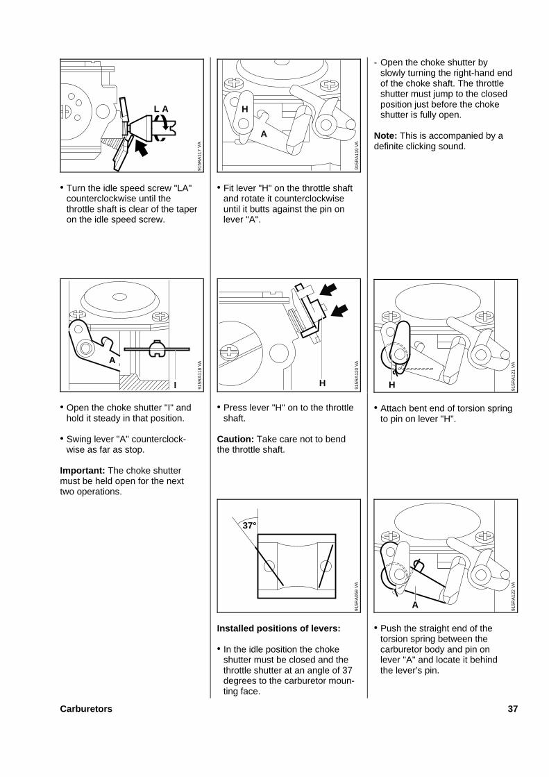
• Turn the idle speed screw "LA"counterclockwise until thethrottle shaft is clear of the taperon the idle speed screw.
• Open the choke shutter "I" andhold it steady in that position.
• Swing lever "A" counterclock-wise as far as stop.
Important: The choke shuttermust be held open for the nexttwo operations.
• Fit lever "H" on the throttle shaftand rotate it counterclockwiseuntil it butts against the pin onlever "A".
• Press lever "H" on to the throttleshaft.
Caution: Take care not to bendthe throttle shaft.
Installed positions of levers:
• In the idle position the chokeshutter must be closed and thethrottle shutter at an angle of 37degrees to the carburetor moun-ting face.
- Open the choke shutter byslowly turning the right-hand endof the choke shaft. The throttleshutter must jump to the closedposition just before the chokeshutter is fully open.
Note: This is accompanied by adefinite clicking sound.
• Attach bent end of torsion springto pin on lever "H".
• Push the straight end of thetorsion spring between thecarburetor body and pin onlever "A" and locate it behindthe lever’s pin.
VA
915R
A11
7
L A
VA
915R
A11
9
A
H
VA
915R
A11
8
A
I
VA
915R
A12
0
H
VA
915R
A05
9
37°
VA
915R
A12
1
H
VA
915R
A12
2
A
Carburetors 37
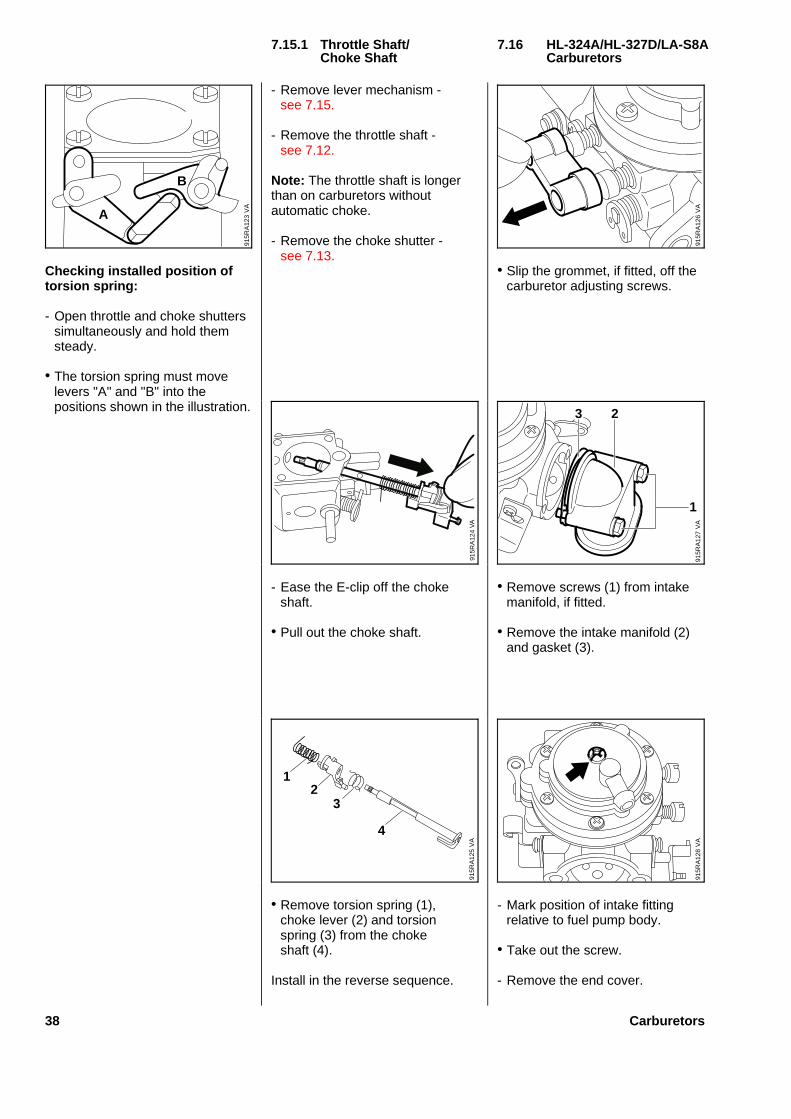
Checkin g installe d positio n oftorsio n spring:
- Open throttle and choke shutterssimultaneously and hold themsteady.
• The torsion spring must movelevers "A" and "B" into thepositions shown in the illustration.
- Remove lever mechanism -see 7.15.
- Remove the throttle shaft -see 7.12.
Note: The throttle shaft is longerthan on carburetors withoutautomatic choke.
- Remove the choke shutter -see 7.13.
- Ease the E-clip off the chokeshaft.
• Pull out the choke shaft.
• Remove torsion spring (1),choke lever (2) and torsionspring (3) from the chokeshaft (4).
Install in the reverse sequence.
• Slip the grommet, if fitted, off thecarburetor adjusting screws.
• Remove screws (1) from intakemanifold, if fitted.
• Remove the intake manifold (2)and gasket (3).
- Mark position of intake fittingrelative to fuel pump body.
• Take out the screw.
- Remove the end cover.
7.15.1 Throttl e Shaft/ 7.16 HL-324A/HL-327D/LA-S8AChok e Shaft Carburetors
B
VA
915R
A12
3A
VA
915R
A12
4V
A91
5RA
125
12
3
4
VA
915R
A12
6V
A91
5RA
127
3 2
1
VA
915R
A12
8
38 Carburetors
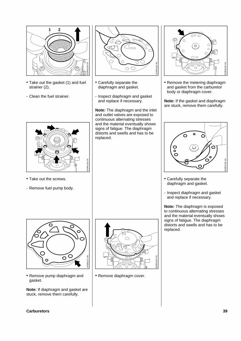
• Take out the gasket (1) and fuelstrainer (2).
- Clean the fuel strainer.
• Take out the screws.
- Remove fuel pump body.
• Remove pump diaphragm andgasket.
Note: If diaphragm and gasket arestuck, remove them carefully.
• Carefully separate thediaphragm and gasket.
- Inspect diaphragm and gasketand replace if necessary.
Note: The diaphragm and the inletand outlet valves are exposed tocontinuous alternating stressesand the material eventually showssigns of fatigue. The diaphragmdistorts and swells and has to bereplaced.
• Remove diaphragm cover.
• Remove the metering diaphragmand gasket from the carburetorbody or diaphragm cover.
Note: If the gasket and diaphragmare stuck, remove them carefully.
• Carefully separate thediaphragm and gasket.
- Inspect diaphragm and gasketand replace if necessary.
Note: The diaphragm is exposedto continuous alternating stressesand the material eventually showssigns of fatigue. The diaphragmdistorts and swells and has to bereplaced.
VA
915R
A12
9
21
VA
915R
A13
2
VA
915R
A13
0
VA
915R
A13
3
VA
915R
A13
4V
A91
5RA
135
Carburetors 39
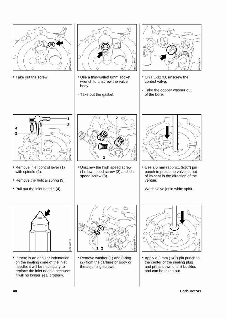
• Take out the screw.
• Remove inlet control lever (1)with spindle (2).
• Remove the helical spring (3).
• Pull out the inlet needle (4).
• If there is an annular indentationon the sealing cone of the inletneedle, it will be necessary toreplace the inlet needle becauseit will no longer seal properly.
• Use a thin-walled 8mm socketwrench to unscrew the valvebody.
- Take out the gasket.
• Unscrew the high speed screw(1), low speed screw (2) and idlespeed screw (3).
• Remove washer (1) and 0-ring(2) from the carburetor body orthe adjusting screws.
• On HL-327D, unscrew thecontrol valve.
- Take the copper washer outof the bore.
• Use a 5 mm (approx. 3/16") pinpunch to press the valve jet outof its seat in the direction of theventuri.
- Wash valve jet in white spirit.
• Apply a 3 mm (1/8") pin punch tothe center of the sealing plugand press down until it bucklesand can be taken out.
VA
915R
A13
6
VA
915R
A13
9
VA
915R
A13
7
24
3
1
VA
915R
A14
0
3
1 2
VA
915R
A13
8
1 2
VA
915R
A14
1
VA
915R
A14
2V
A91
5RA
143
VA
915R
A14
4
40 Carburetors
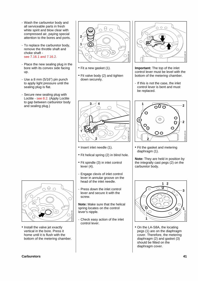
- Wash the carburetor body andall serviceable parts in freshwhite spirit and blow clear withcompressed air, paying specialattention to the bores and ports.
- To replace the carburetor body,remove the throttle shaft andchoke shaft -see 7.16.1 and 7.16.2.
- Place the new sealing plug in thebore with its convex side facingup.
- Use a 8 mm (5/16") pin punchto apply light pressure until thesealing plug is flat.
- Secure new sealing plug withLoctite - see 8.2. (Apply Loctiteto gap between carburetor bodyand sealing plug.)
• Install the valve jet exactlyvertical in the bore. Press ithome until it is flush with thebottom of the metering chamber.
• Fit a new gasket (1).
• Fit valve body (2) and tightendown securely.
• Insert inlet needle (1).
• Fit helical spring (2) in blind hole.
• Fit spindle (3) in inlet controllever (4).
- Engage clevis of inlet controllever in annular groove on thehead of the inlet needle.
- Press down the inlet controllever and secure it with thescrew.
Note: Make sure that the helicalspring locates on the controllever’s nipple.
- Check easy action of the inletcontrol lever.
Important : The top of the inletcontrol lever must be level with thebottom of the metering chamber.
- If this is not the case, the inletcontrol lever is bent and mustbe replaced.
• Fit the gasket and meteringdiaphragm (1).
Note: They are held in position bythe integrally cast pegs (2) on thecarburetor body.
• On the LA-S8A, the locatingpegs (1) are on the diaphragmcover. Therefore, the meteringdiaphragm (2) and gasket (3)should be fitted on thediaphragm cover.
VA
915R
A14
6
2
1
VA
915R
A14
8V
A91
5RA
149
2
2
2
1
VA
915R
A14
5
1
1
3
1 2V
A91
5RA
150
Carburetors 41
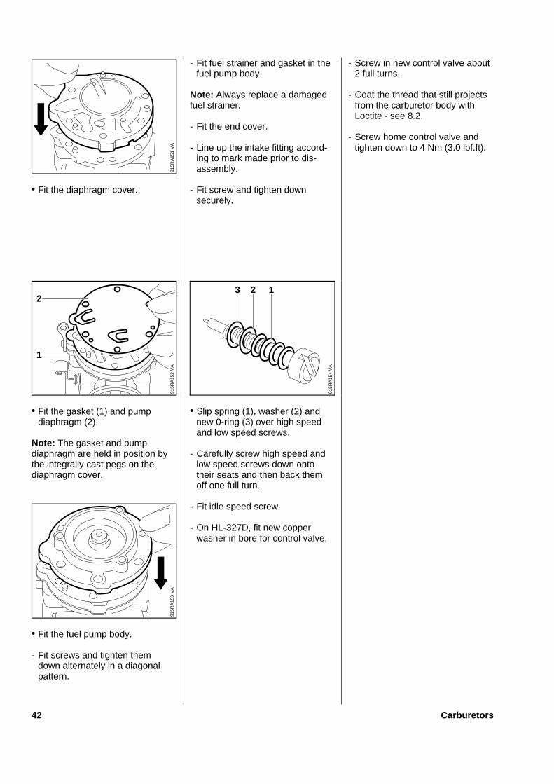
• Fit the diaphragm cover.
• Fit the gasket (1) and pumpdiaphragm (2).
Note: The gasket and pumpdiaphragm are held in position bythe integrally cast pegs on thediaphragm cover.
• Fit the fuel pump body.
- Fit screws and tighten themdown alternately in a diagonalpattern.
- Fit fuel strainer and gasket in thefuel pump body.
Note: Always replace a damagedfuel strainer.
- Fit the end cover.
- Line up the intake fitting accord-ing to mark made prior to dis-assembly.
- Fit screw and tighten downsecurely.
• Slip spring (1), washer (2) andnew 0-ring (3) over high speedand low speed screws.
- Carefully screw high speed andlow speed screws down ontotheir seats and then back themoff one full turn.
- Fit idle speed screw.
- On HL-327D, fit new copperwasher in bore for control valve.
- Screw in new control valve about2 full turns.
- Coat the thread that still projectsfrom the carburetor body withLoctite - see 8.2.
- Screw home control valve andtighten down to 4 Nm (3.0 lbf.ft).V
A91
5RA
151
VA
915R
A15
2
2
1
VA
915R
A15
4
123
VA
915R
A15
3
42 Carburetors
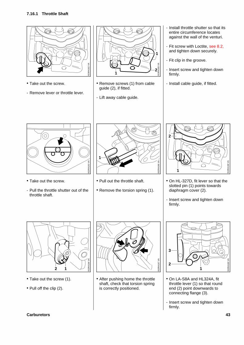
• Take out the screw.
- Remove lever or throttle lever.
• Take out the screw.
- Pull the throttle shutter out of thethrottle shaft.
• Take out the screw (1).
• Pull off the clip (2).
• Remove screws (1) from cableguide (2), if fitted.
- Lift away cable guide.
• Pull out the throttle shaft.
• Remove the torsion spring (1).
• After pushing home the throttleshaft, check that torsion springis correctly positioned.
- Install throttle shutter so that itsentire circumference locatesagainst the wall of the venturi.
- Fit screw with Loctite, see 8.2,and tighten down securely.
- Fit clip in the groove.
- Insert screw and tighten downfirmly.
- Install cable guide, if fitted.
• On HL-327D, fit lever so that theslotted pin (1) points towardsdiaphragm cover (2).
- Insert screw and tighten downfirmly.
• On LA-S8A and HL324A, fitthrottle lever (1) so that roundend (2) point downwards toconnecting flange (3).
- Insert screw and tighten downfirmly.
7.16.1 Throttl e Shaft
VA
915R
A16
2
VA
915R
A16
5
1
21
VA
915R
A16
3
VA
915R
A16
61
VA
915R
A16
8
2
1
VA
915R
A16
4
12
VA
915R
A16
7
VA
915R
A16
9
2
3
1
Carburetors 43

- Remove the intake manifold, iffitted - see 7.16.
• Ease the E-clip (1) off thegovernor rod (2), if fitted.
- Remove the governor rod.
• On LA-S8A and HL327D, takeout the screw (1).
• Remove the governor lever (2).
• Take out the screw.
- Pull the choke shutter out of thechoke shaft.
• On HL-327D and HL-324A, takeout the screw (1).
• Pull off the clip (2).
• Withdraw the choke shaft.
Note: On HL-327D, carefully with-draw choke shaft so that the balldoes not pop out and be lost.
- Slide choke shaft into thecarburetor from the adjustingscrew side.
Note: On HL-327D, fit the spring(1) and ball (2).
• Push home the choke shaft untilthe ball engages the groove (3).
- Fit clip in groove in choke shaft.
- Secure clip with screw.
• On LA-S8A and HL327D, rotatechoke shaft so that slot (1) ishorizontal and the flat side (2)points down.
7.16.2 Chok e Shaft
VA
915R
A15
5
2
1
VA
915R
A15
8
21
VA
915R
A16
0
2
1
3V
A91
5RA
156
12
VA
915R
A15
9
VA
915R
A15
7
VA
915R
A16
1
2 1
44 Carburetors

• On HL-324A, rotate choke shaftso that the pin (1) points forward.
• Fit the choke shutter so that thehole (2) points forward and theindentations (3) face the endcover.
- Fit screw with Loctite, see 8.2,and tighten down securely.
- On LA-S8A and HL327D, closethe choke shutter.
• Fit governor lever (1) so that thepin (2) lines up with the center ofthe high speed screw (3).
- Fit screw and tighten downsecurely.
• Take out the screws (1).
• Remove the end cover (2) withcap.
• Pull out the cap.
• Remove the flange.
• Take valve out of flange.
- Check valve and replace ifnecessary.
Note: If the circuit for filling themetering chamber is malfunction-ing, if the valve is dirty, distortedor damaged, install a new valve.
• Remove metering diaphragmand gasket.
Note: If the gasket and diaphragmare stuck, remove them carefully.
VA
915R
A05
5
2 1
3
VA
915R
A19
2
2
1 1
11
VA
915R
A19
1
VA
915R
A19
3
VA
915R
A17
1
3
12
VA
915R
A19
4
VA
915R
A19
6
7.17 WYL-63 / WYL-73Rotar y Valve Carburetors
Carburetors 45
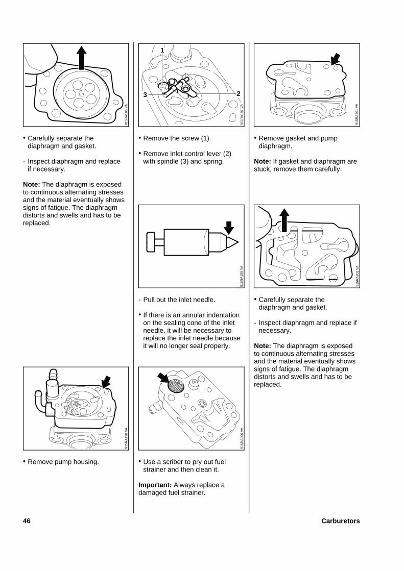
• Carefully separate thediaphragm and gasket.
- Inspect diaphragm and replaceif necessary.
Note: The diaphragm is exposedto continuous alternating stressesand the material eventually showssigns of fatigue. The diaphragmdistorts and swells and has to bereplaced.
• Remove pump housing.
• Remove the screw (1).
• Remove inlet control lever (2)with spindle (3) and spring.
- Pull out the inlet needle.
• If there is an annular indentationon the sealing cone of the inletneedle, it will be necessary toreplace the inlet needle becauseit will no longer seal properly.
• Use a scriber to pry out fuelstrainer and then clean it.
Important: Always replace adamaged fuel strainer.
• Remove gasket and pumpdiaphragm.
Note: If gasket and diaphragm arestuck, remove them carefully.
• Carefully separate thediaphragm and gasket.
- Inspect diaphragm and replace ifnecessary.
Note: The diaphragm is exposedto continuous alternating stressesand the material eventually showssigns of fatigue. The diaphragmdistorts and swells and has to bereplaced.
VA
915R
A19
5
VA
915R
A19
7
1
23
VA
915R
A20
1
VA
915R
A19
9
VA
915R
A20
2
VA
915R
A19
8
VA
915R
A20
0
46 Carburetors

• Remove the spring.
• Use a scriber to carefully easethe main jet out of its seat.
- Remove the sealing ring.
• Take out the screws (1).
• Pull out the control valve (2).
• If necessary, pry off the retainingring (1) and pull out the slottedpin (2) with washer (3).
• Take out the idle speedscrew (4).
- Wash the carburetor body andall serviceable parts in freshwhite spirit and blow clear with
compressed air, paying specialattention to the bores and ports.
• Install the control valve so thatthe idle speed screw (1) points tothe left - viewed from stub (2).
- Insert screws and tighten downsecurely.
• Slip 0-ring (1) over the mainjet (2).
- Press main jet into carburetorseat as far as stop.
Note: Check size of main jet(number on main jet):40 = WYL-6336 = WYL-73
VA
915R
A20
3
VA
915R
A20
6
3
4
2
1
VA
915R
A20
4
40
VA
915R
A20
5
1
1
2
VA
915R
A20
7
2
1V
A91
5RA
208
1
2
Carburetors 47
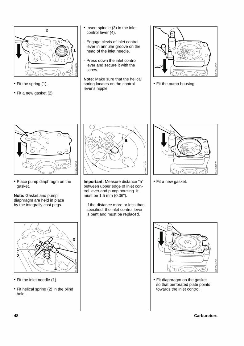
• Fit the spring (1).
• Fit a new gasket (2).
• Place pump diaphragm on thegasket.
Note: Gasket and pumpdiaphragm are held in placeby the integrally cast pegs.
• Fit the inlet needle (1).
• Fit helical spring (2) in the blindhole.
• Insert spindle (3) in the inletcontrol lever (4).
- Engage clevis of inlet controllever in annular groove on thehead of the inlet needle.
- Press down the inlet controllever and secure it with thescrew.
Note: Make sure that the helicalspring locates on the controllever’s nipple.
Important: Measure distance "a"between upper edge of inlet con-trol lever and pump housing. Itmust be 1.5 mm (0.06").
- If the distance more or less thanspecified, the inlet control leveris bent and must be replaced.
• Fit the pump housing.
• Fit a new gasket.
• Fit diaphragm on the gasketso that perforated plate pointstowards the inlet control.
2
VA
915R
A20
9
1
VA
915R
A21
3
VA
915R
A21
0
a91
5RA
212
VA
VA
915R
A21
4
VA
915R
A21
1
1
2
3
4
VA
915R
A21
5
48 Carburetors
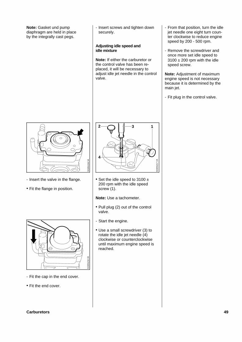
Note: Gasket und pumpdiaphragm are held in placeby the integrally cast pegs.
- Insert the valve in the flange.
• Fit the flange in position.
- Fit the cap in the end cover.
• Fit the end cover.
- Insert screws and tighten downsecurely.
Adjusting idle speed andidle mixture
Note: If either the carburetor orthe control valve has been re-placed, it will be necessary toadjust idle jet needle in the controlvalve.
• Set the idle speed to 3100 ±200 rpm with the idle speedscrew (1).
Note: Use a tachometer.
• Pull plug (2) out of the controlvalve.
- Start the engine.
• Use a small screwdriver (3) torotate the idle jet needle (4)clockwise or counterclockwiseuntil maximum engine speed isreached.
- From that position, turn the idlejet needle one eight turn coun-ter clockwise to reduce enginespeed by 200 - 500 rpm.
- Remove the screwdriver andonce more set idle speed to3100 ± 200 rpm with the idlespeed screw.
Note: Adjustment of maximumengine speed is not necessarybecause it is determined by themain jet.
- Fit plug in the control valve.
VA
915R
A19
4V
A91
5RA
216
VA
915R
A21
7
1
4
2 3
Carburetors 49
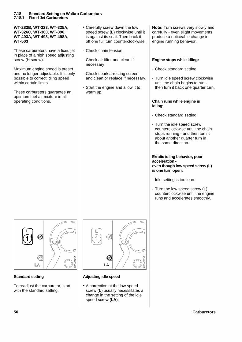
WT-283B, WT-323, WT-325A,WT-326C, WT-360, WT-396,WT-403A, WT-493, WT-498A,WT-503
These carburetors have a fixed jetin place of a high speed adjustingscrew (H screw).
Maximum engine speed is presetand no longer adjustable. It is onlypossible to correct idling speedwithin certain limits.
These carburetors guarantee anoptimum fuel-air mixture in alloperating conditions.
Standard setting
To readjust the carburetor, startwith the standard setting.
• Carefully screw down the lowspeed screw (L) clockwise until itis against its seat. Then back itoff one full turn counterclockwise.
- Check chain tension.
- Check air filter and clean ifnecessary.
- Check spark arresting screenand clean or replace if necessary.
- Start the engine and allow it towarm up.
Adjusting idle speed
• A correction at the low speedscrew (L) usually necessitates achange in the setting of the idlespeed screw (LA ).
Note: Turn screws very slowly andcarefully - even slight movementsproduce a noticeable change inengine running behavior.
Engine stops while idling:
- Check standard setting.
- Turn idle speed screw clockwiseuntil the chain begins to run -then turn it back one quarter turn.
Chain runs while engine isidling:
- Check standard setting.
- Turn the idle speed screwcounterclockwise until the chainstops running - and then turn itabout another quarter turn inthe same direction.
Erratic idling behavior, pooracceleration -even though low speed screw (L)is one turn open:
- Idle setting is too lean.
- Turn the low speed screw (L)counterclockwise until the engineruns and accelerates smoothly.
VA
915R
A29
4
L
VA
915R
A29
5
LA
7.18 Standard Setting on Walbro Carburetors7.18.1 Fixed Jet Carburetors
50 Carburetors
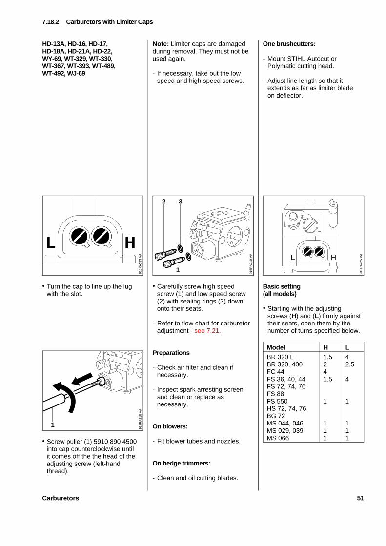
HD-13A, HD-16, HD-17,HD-18A, HD-21A, HD-22,WY-69, WT-329, WT-330,WT-367, WT-393, WT-489,WT-492, WJ-69
• Turn the cap to line up the lugwith the slot.
• Screw puller (1) 5910 890 4500into cap counterclockwise untilit comes off the the head of theadjusting screw (left-handthread).
Note: Limiter caps are damagedduring removal. They must not beused again.
- If necessary, take out the lowspeed and high speed screws.
• Carefully screw high speedscrew (1) and low speed screw(2) with sealing rings (3) downonto their seats.
- Refer to flow chart for carburetoradjustment - see 7.21.
Preparations
- Check air filter and clean ifnecessary.
- Inspect spark arresting screenand clean or replace asnecessary.
On blowers:
- Fit blower tubes and nozzles.
On hedg e tri mmers:
- Clean and oil cutting blades.
One brushcutters:
- Mount STIHL Autocut orPolymatic cutting head.
- Adjust line length so that itextends as far as limiter bladeon deflector.
Basi c setting(all models)
• Starting with the adjustingscrews (H) and (L) firmly againsttheir seats, open them by thenumber of turns specified below.
Model H LBR 320 LBR 320, 400FC 44FS 36, 40, 44FS 72, 74, 76FS 88FS 550HS 72, 74, 76BG 72MS 044, 046MS 029, 039MS 066
1.5241.5
1
111
42.5
4
1
111
7.18.2 Carburetor s wit h Limiter Caps
VA
915R
A21
8
1
VA
915R
A21
9
2 3
1
VA
915R
A22
5
VA
915R
A29
3
Carburetors 51
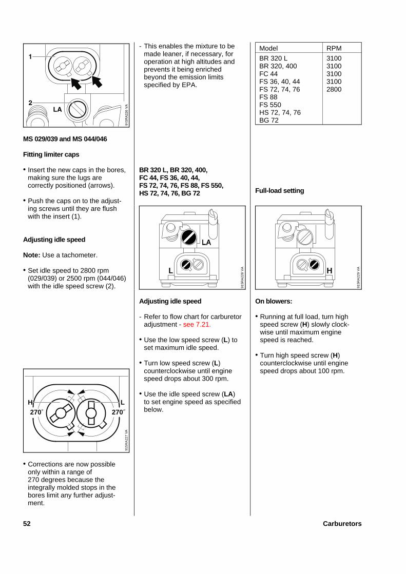
MS 029/039 and MS 044/046
Fittin g limiter caps
• Insert the new caps in the bores,making sure the lugs arecorrectly positioned (arrows).
• Push the caps on to the adjust-ing screws until they are flushwith the insert (1).
Adju stin g idle speed
Note: Use a tachometer.
• Set idle speed to 2800 rpm(029/039) or 2500 rpm (044/046)with the idle speed screw (2).
• Corrections are now possibleonly within a range of270 degrees because theintegrally molded stops in thebores limit any further adjust-ment.
- This enables the mixture to bemade leaner, if necessary, foroperation at high altitudes andprevents it being enrichedbeyond the emission limitsspecified by EPA.
BR 320 L, BR 320, 400,FC 44, FS 36, 40, 44,FS 72, 74, 76, FS 88, FS 550,HS 72, 74, 76, BG 72
Adju stin g idle speed
- Refer to flow chart for carburetoradjustment - see 7.21.
• Use the low speed screw (L) toset maximum idle speed.
• Turn low speed screw (L)counterclockwise until enginespeed drops about 300 rpm.
• Use the idle speed screw (LA)to set engine speed as specifiedbelow.
Model RPM
BR 320 LBR 320, 400FC 44FS 36, 40, 44FS 72, 74, 76FS 88FS 550HS 72, 74, 76BG 72
31003100310031002800
Full-loa d setting
On blowers:
• Running at full load, turn highspeed screw (H) slowly clock-wise until maximum enginespeed is reached.
• Turn high speed screw (H)counterclockwise until enginespeed drops about 100 rpm.
VA
915R
A22
9
VA
915R
A22
7
270 270H L
VA
915R
A22
8
52 Carburetors
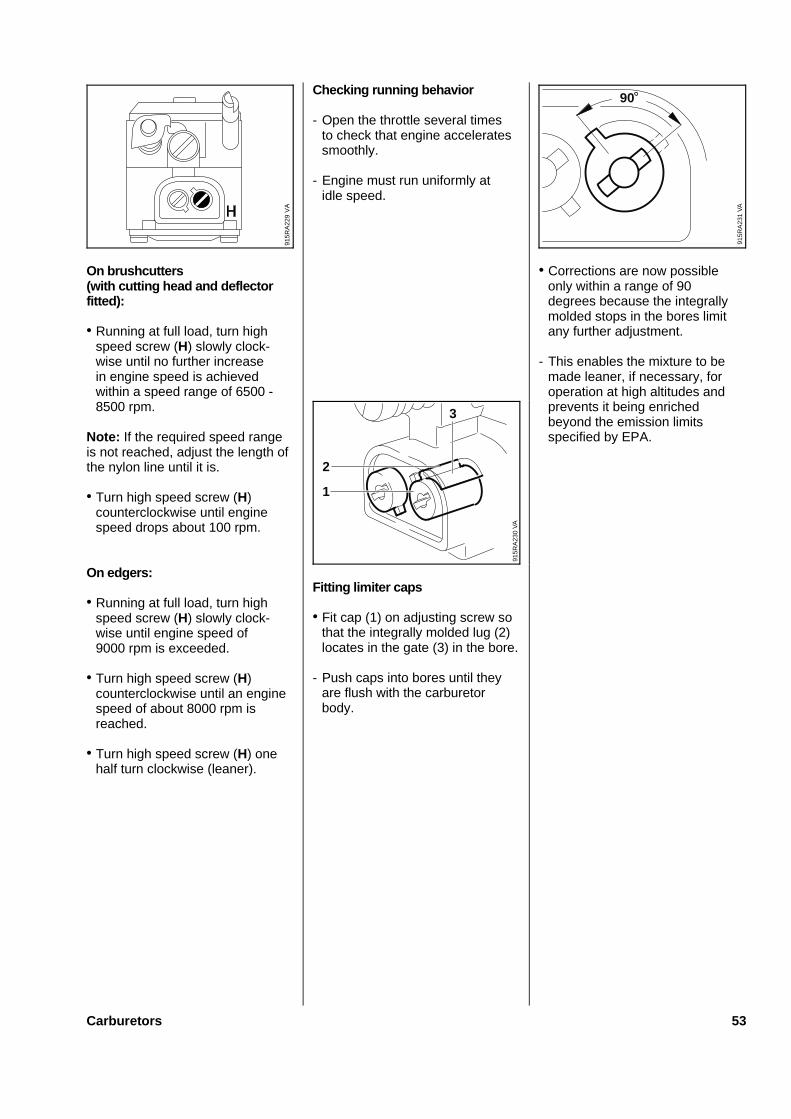
On brushcutters(with cutting head and deflectorfitted):
• Running at full load, turn highspeed screw (H) slowly clock-wise until no further increasein engine speed is achievedwithin a speed range of 6500 -8500 rpm.
Note: If the required speed rangeis not reached, adjust the length ofthe nylon line until it is.
• Turn high speed screw (H)counterclockwise until enginespeed drops about 100 rpm.
On edgers:
• Running at full load, turn highspeed screw (H) slowly clock-wise until engine speed of9000 rpm is exceeded.
• Turn high speed screw (H)counterclockwise until an enginespeed of about 8000 rpm isreached.
• Turn high speed screw (H) onehalf turn clockwise (leaner).
Checking running behavior
- Open the throttle several timesto check that engine acceleratessmoothly.
- Engine must run uniformly atidle speed.
Fitting limiter caps
• Fit cap (1) on adjusting screw sothat the integrally molded lug (2)locates in the gate (3) in the bore.
- Push caps into bores until theyare flush with the carburetorbody.
• Corrections are now possibleonly within a range of 90degrees because the integrallymolded stops in the bores limitany further adjustment.
- This enables the mixture to bemade leaner, if necessary, foroperation at high altitudes andprevents it being enrichedbeyond the emission limitsspecified by EPA.
VA
915R
A22
9
VA
915R
A23
0
3
1
2
VA
915R
A23
1
90
Carburetors 53

C1Q-S30C, C1Q-S37A, C1Q-S41,C1Q-S42, C1Q-S34B, C1Q-S36B
These carburetors have a fixed jetin place of a high speed adjustingscrew (H screw).
C1Q-S34B and C1Q-S36B carbu-retors (FS 300...450) have no lowspeed screw (L screw).
Maximum engine speed is presetand no longer adjustable. It is onlypossible to correct idling speedwithin certain limits.
These carburetors guarantee anoptimum fuel-air mixture in alloperating conditions.
Standard setting
To readjust the carburetor, startwith the standard setting.
• Carefully screw down the lowspeed screw (L) clockwise until itis against its seat. Then back itoff one full turn counterclockwise.
- Mount an approved cutting tool.
If cutting head is fitted:- Adjust nylon line to correct
length. Each line must extendas far as limiter blade on thedeflector.
- On HS 75, 80, 85, checkcutting blades and clean ifnecessary (they must be clean,move freely and not be warped).
- Check air filter and clean ifnecessary.
- Inspect spark arresting screenand clean or replace asnecessary.
- Start the engine and allow itto warm up.
Adjusting idle speed
Engine stops while idling:
- Check standard setting.
• Turn idle speed screw (LA )clockwise until the cutting headbegins to rotate - then turn itback one half turn.
• On HS 75, 80, 85, use the idlespeed screw (LA ) to set idlespeed to 2800 rpm.
Cutting head rotates whileengine is idling:
- Check standard setting.
- Turn the idle speed screw (LA )counterclockwise until the cuttinghead stops rotating - and thenturn it about another half turn inthe same direction.
Engine accelerates poorlyor stops after idling for longperiod:
- Check standard setting.
- Turn low speed screw (L) onequarter turn counterclockwise.
- Use idle speed screw (LA ) to setengine speed to 2800 rpm,repeat both settings if necessary.
Engine stops while being swung,during transition from full load toidle or idles erratically:
- Check standard setting.
- Turn low speed screw (L) oneeight turn clockwise.
- Use idle speed screw (LA ) toset engine speed to 2800 rpm,repeat both settings if necessary.
7.19 Standard Setting on Zama Carburetors7.19.1 Fixed Jet Carburetors
VA
915R
A29
6
54 Carburetors
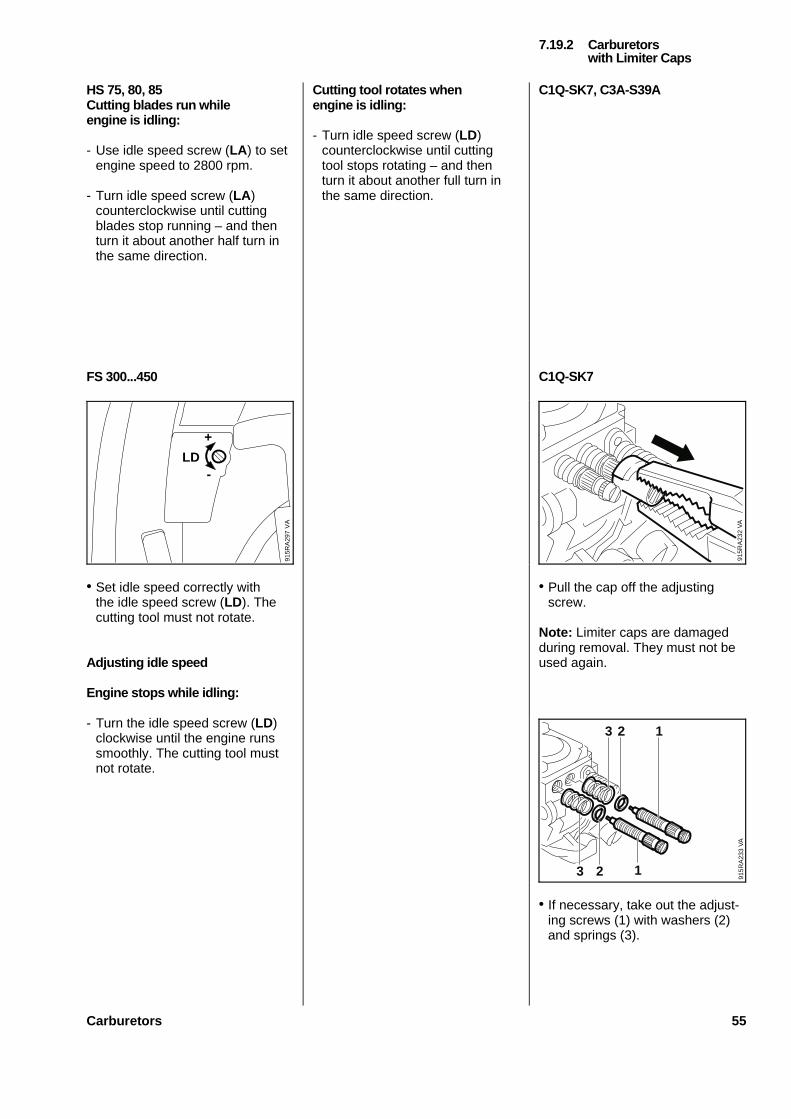
HS 75, 80, 85Cutting blades run whileengine is idling:
- Use idle speed screw (LA ) to setengine speed to 2800 rpm.
- Turn idle speed screw (LA )counterclockwise until cuttingblades stop running – and thenturn it about another half turn inthe same direction.
FS 300...450
• Set idle speed correctly withthe idle speed screw (LD). Thecutting tool must not rotate.
Adjusting idle speed
Engine stops while idling:
- Turn the idle speed screw (LD)clockwise until the engine runssmoothly. The cutting tool mustnot rotate.
Cutting tool rotates whenengine is idling:
- Turn idle speed screw (LD)counterclockwise until cuttingtool stops rotating – and thenturn it about another full turn inthe same direction.
C1Q-SK7, C3A-S39A
C1Q-SK7
• Pull the cap off the adjustingscrew.
Note: Limiter caps are damagedduring removal. They must not beused again.
• If necessary, take out the adjust-ing screws (1) with washers (2)and springs (3).
7.19.2 Carburetorswith Limiter Caps
VA
915R
A29
7
LD
+
-
VA
915R
A23
2V
A91
5RA
233
3 22 1
123
Carburetors 55
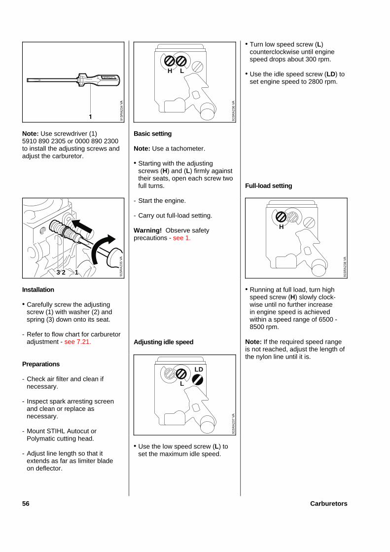
Note: Use screwdriver (1)5910 890 2305 or 0000 890 2300to install the adjusting screws andadjust the carburetor.
Insta llation
• Carefully screw the adjustingscrew (1) with washer (2) andspring (3) down onto its seat.
- Refer to flow chart for carburetoradjustment - see 7.21.
Preparations
- Check air filter and clean ifnecessary.
- Inspect spark arresting screenand clean or replace asnecessary.
- Mount STIHL Autocut orPolymatic cutting head.
- Adjust line length so that itextends as far as limiter bladeon deflector.
Basi c setting
Note: Use a tachometer.
• Starting with the adjustingscrews (H) and (L) firmly againsttheir seats, open each screw twofull turns.
- Start the engine.
- Carry out full-load setting.
Warning ! Observe safetyprecautions - see 1.
Adju stin g idle speed
• Use the low speed screw (L) toset the maximum idle speed.
• Turn low speed screw (L)counterclockwise until enginespeed drops about 300 rpm.
• Use the idle speed screw (LD) toset engine speed to 2800 rpm.
Full-loa d setting
• Running at full load, turn highspeed screw (H) slowly clock-wise until no further increasein engine speed is achievedwithin a speed range of 6500 -8500 rpm.
Note: If the required speed rangeis not reached, adjust the length ofthe nylon line until it is.
VA
915R
A23
5
3 2 1
VA
915R
A23
6
H L
VA
915R
A23
7
L
LD
VA
915R
A23
8
H
56 Carburetors
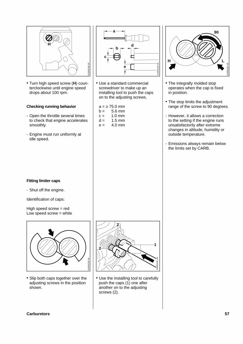
• Turn high speed screw (H) coun-terclockwise until engine speeddrops about 100 rpm.
Checking running behavior
- Open the throttle several timesto check that engine acceleratessmoothly.
- Engine must run uniformly atidle speed.
Fitting limiter caps
- Shut off the engine.
Identification of caps:
High speed screw = redLow speed screw = white
• Slip both caps together over theadjusting screws in the positionshown.
• Use a standard commercialscrewdriver to make up aninstalling tool to push the capson to the adjusting screws.
a = ≥ 75.0 mmb = 5.6 mmc = 1.0 mmd = 1.5 mme = 4.0 mm
• Use the installing tool to carefullypush the caps (1) one afteranother on to the adjustingscrews (2).
• The integrally molded stopoperates when the cap is fixedin position.
• The stop limits the adjustmentrange of the screw to 90 degrees.
- However, it allows a correctionto the setting if the engine runsunsatisfactorily after extremechanges in altitude, humidity oroutside temperature.
- Emissions always remain belowthe limits set by CARB.
VA
915R
A23
8
Hb
c
e
d
VA
915R
A24
0
a
VA
915R
A24
2
90
H L
VA
915R
A23
9
VA
915R
A24
1
2
12
Carburetors 57
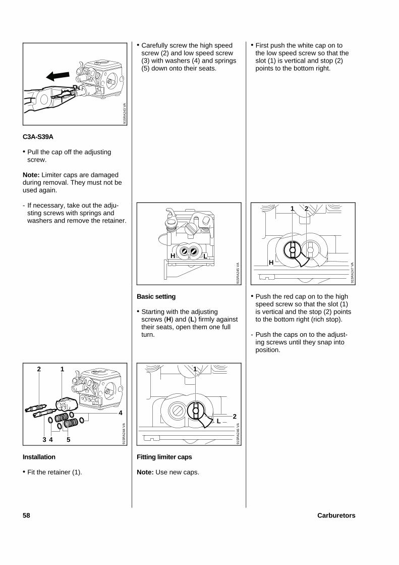
C3A-S39A
• Pull the cap off the adjustingscrew.
Note: Limiter caps are damagedduring removal. They must not beused again.
- If necessary, take out the adju-sting screws with springs andwashers and remove the retainer.
Installation
• Fit the retainer (1).
• Carefully screw the high speedscrew (2) and low speed screw(3) with washers (4) and springs(5) down onto their seats.
Basic setting
• Starting with the adjustingscrews (H) and (L) firmly againsttheir seats, open them one fullturn.
Fitting limiter caps
Note: Use new caps.
• First push the white cap on tothe low speed screw so that theslot (1) is vertical and stop (2)points to the bottom right.
• Push the red cap on to the highspeed screw so that the slot (1)is vertical and the stop (2) pointsto the bottom right (rich stop).
- Push the caps on to the adjust-ing screws until they snap intoposition.
VA
915R
A24
3
VA
915R
A24
5
H L
VA
915R
A24
7
1 2
H
VA
915R
A24
4
3 5
4
2 1
4
VA
915R
A24
6
2
1
L
58 Carburetors

• The two stops limit the range ofadjustment.
• Corrections are now possibleonly within a range of270 degrees.
- This enables the mixture to bemade leaner, if necessary, foroperation at high altitudes andprevents it being enrichedbeyond the emission limitsspecified by EPA.
Adjusting idle speed
Note: Use a tachometer.
- Use idle speed screw (LA ) to setengine speed to 2800 rpm.
HS-275A, HS-279B
These carburetors have a fixed jetin place of a high speed adjustingscrew (H screw).
Maximum engine speed is presetand no longer adjustable. It is onlypossible to correct idling speedwithin certain limits.
These carburetors guarantee anoptimum fuel-air mixture in alloperating conditions.
Standard setting
To readjust the carburetor, startwith the standard setting.
• Carefully screw down the lowspeed screw (L) clockwise until itis against its seat. Then back itoff one full turn counterclockwise.
- Check air filter and clean ifnecessary.
- Inspect spark arresting screenand clean or replace asnecessary.
- Start the engine and allow it towarm up.
Adjusting idle speed
Note: Use a tachometer.
• Use idle speed screw (LA ) to setengine speed to 2500 rpm.
VA
915R
A24
8V
A91
5RA
249
270
VA
915R
A25
0
L
LA
7.20 Standard Setting on Tillotson Carburetors7.20.1 Fixed Jet Carburetors
Carburetors 59
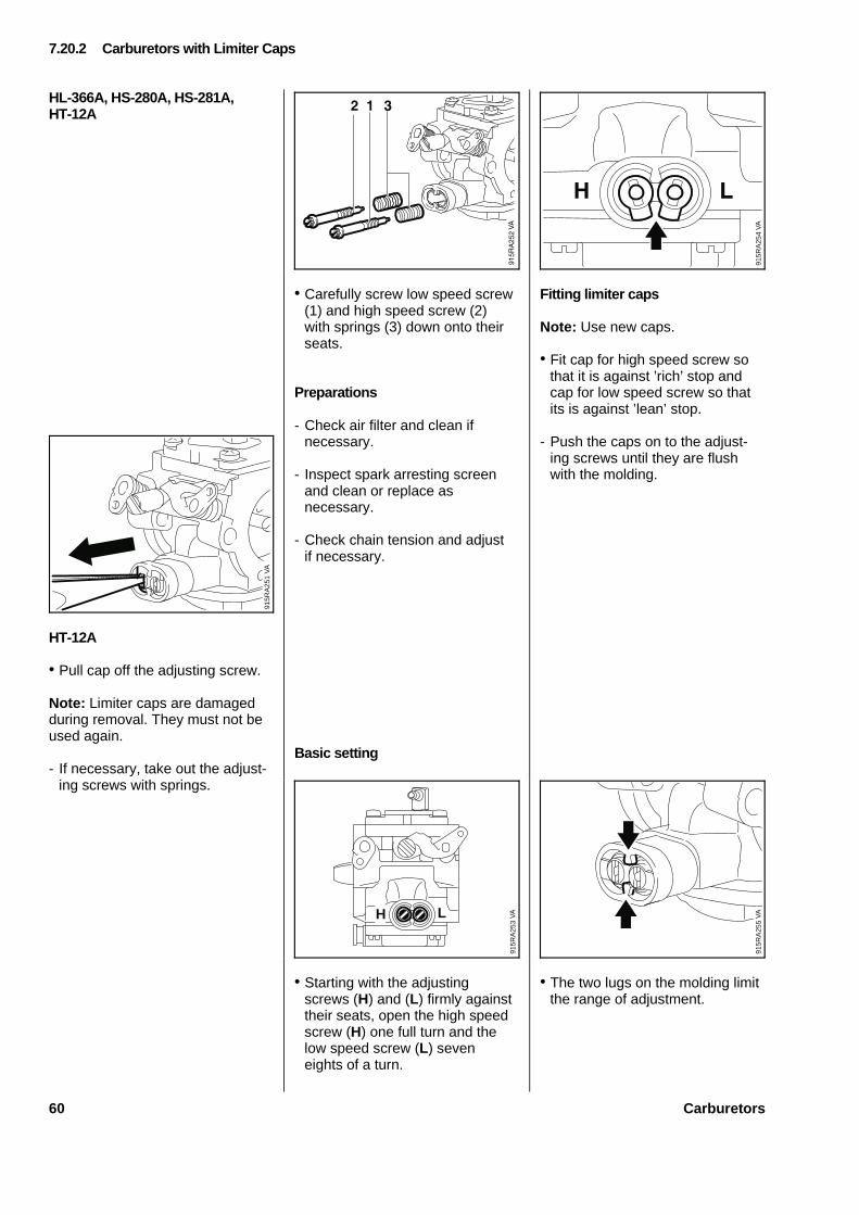
HL-366A, HS-280A, HS-281A,HT-12A
HT-12A
• Pull cap off the adjusting screw.
Note: Limiter caps are damagedduring removal. They must not beused again.
- If necessary, take out the adjust-ing screws with springs.
• Carefully screw low speed screw(1) and high speed screw (2)with springs (3) down onto theirseats.
Preparations
- Check air filter and clean ifnecessary.
- Inspect spark arresting screenand clean or replace asnecessary.
- Check chain tension and adjustif necessary.
Basic setting
• Starting with the adjustingscrews (H) and (L) firmly againsttheir seats, open the high speedscrew (H) one full turn and thelow speed screw (L) seveneights of a turn.
Fitting limiter caps
Note: Use new caps.
• Fit cap for high speed screw sothat it is against ’rich’ stop andcap for low speed screw so thatits is against ’lean’ stop.
- Push the caps on to the adjust-ing screws until they are flushwith the molding.
• The two lugs on the molding limitthe range of adjustment.
7.20.2 Carburetors with Limiter Caps
VA
915R
A25
1
VA
915R
A25
4
VA
915R
A25
3
LH VA
915R
A25
5
60 Carburetors
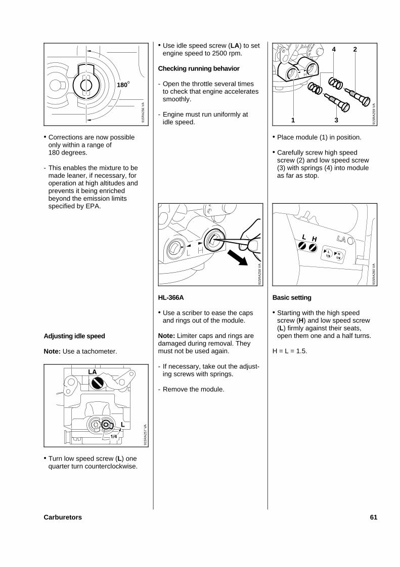
• Corrections are now possibleonly within a range of180 degrees.
- This enables the mixture to bemade leaner, if necessary, foroperation at high altitudes andprevents it being enrichedbeyond the emission limitsspecified by EPA.
Adjusting idle speed
Note: Use a tachometer.
• Turn low speed screw (L) onequarter turn counterclockwise.
• Use idle speed screw (LA ) to setengine speed to 2500 rpm.
Checking running behavior
- Open the throttle several timesto check that engine acceleratessmoothly.
- Engine must run uniformly atidle speed.
HL-366A
• Use a scriber to ease the capsand rings out of the module.
Note: Limiter caps and rings aredamaged during removal. Theymust not be used again.
- If necessary, take out the adjust-ing screws with springs.
- Remove the module.
• Place module (1) in position.
• Carefully screw high speedscrew (2) and low speed screw(3) with springs (4) into moduleas far as stop.
Basic setting
• Starting with the high speedscrew (H) and low speed screw(L) firmly against their seats,open them one and a half turns.
H = L = 1.5.
VA
915R
A25
6
180
VA
915R
A25
9
4 2
31
VA
915R
A25
8
VA
915R
A25
7
VA
915R
A26
0
Carburetors 61
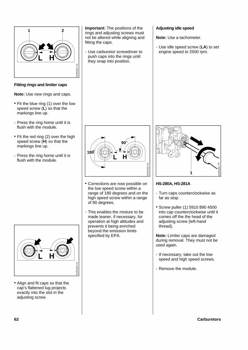
Fitting rings and limiter caps
Note: Use new rings and caps.
• Fit the blue ring (1) over the lowspeed screw (L) so that themarkings line up.
- Press the ring home until it isflush with the module.
• Fit the red ring (2) over the highspeed screw (H) so that themarkings line up.
- Press the ring home until it isflush with the module.
• Align and fit caps so that thecap’s flattened lug projectsexactly into the slot in theadjusting screw.
Important: The positions of therings and adjusting screws mustnot be altered while aligning andfitting the caps.
- Use carburetor screwdriver topush caps into the rings untilthey snap into position.
• Corrections are now possible onthe low speed screw within arange of 180 degrees and on thehigh speed screw within a rangeof 90 degrees.
- This enables the mixture to bemade leaner, if necessary, foroperation at high altitudes andprevents it being enrichedbeyond the emission limitsspecified by EPA.
Adjusting idle speed
Note: Use a tachometer.
- Use idle speed screw (LA ) to setengine speed to 2500 rpm.
HS-280A, HS-281A
- Turn caps counterclockwise asfar as stop.
• Screw puller (1) 5910 890 4500into cap counterclockwise until itcomes off the the head of theadjusting screw (left-handthread).
Note: Limiter caps are damagedduring removal. They must not beused again.
- If necessary, take out the lowspeed and high speed screws.
- Remove the module.
915R
A26
1
1 2
VA
VA
915R
A26
3
180
90
VA
915R
A26
4
1
VA
915R
A26
2
62 Carburetors
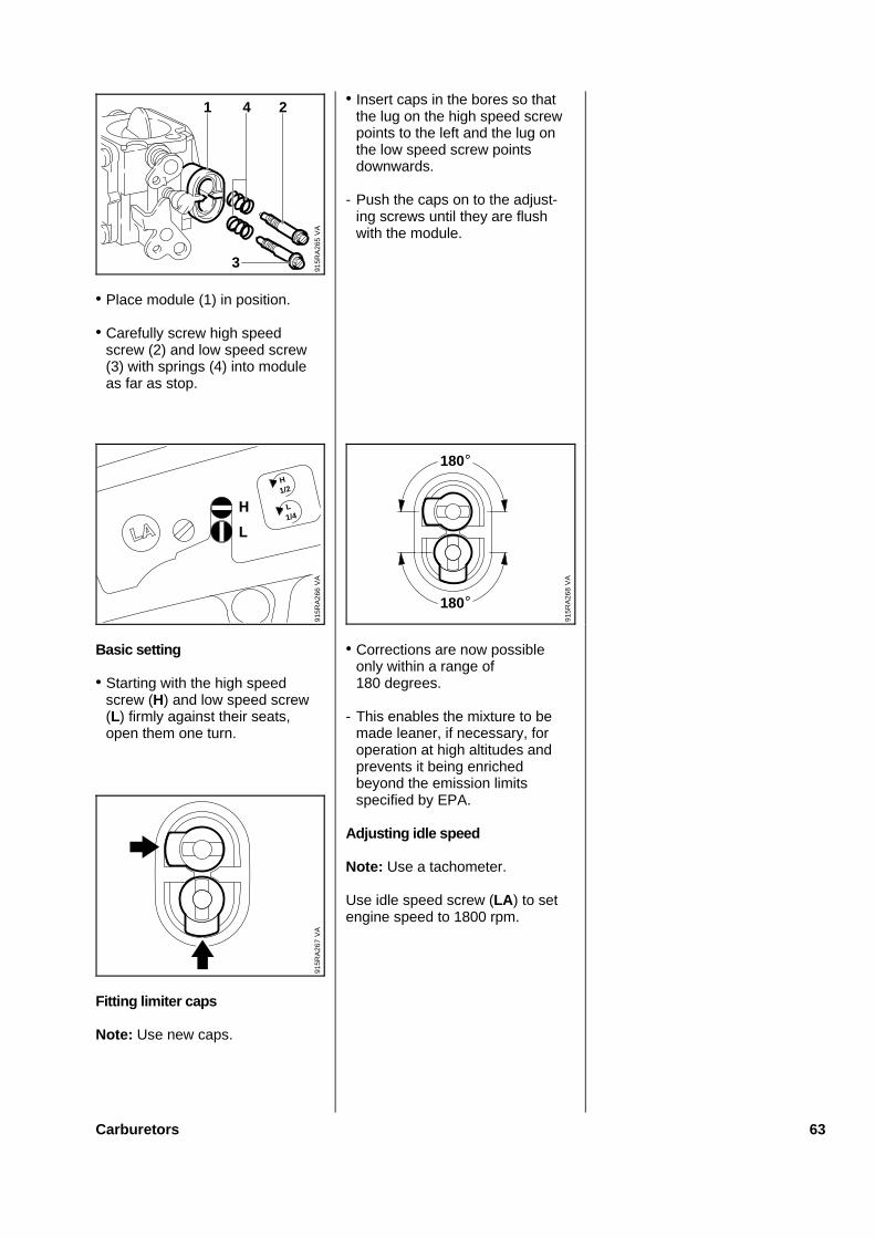
• Place module (1) in position.
• Carefully screw high speedscrew (2) and low speed screw(3) with springs (4) into moduleas far as stop.
Basic setting
• Starting with the high speedscrew (H) and low speed screw(L) firmly against their seats,open them one turn.
Fitting limiter caps
Note: Use new caps.
• Insert caps in the bores so thatthe lug on the high speed screwpoints to the left and the lug onthe low speed screw pointsdownwards.
- Push the caps on to the adjust-ing screws until they are flushwith the module.
• Corrections are now possibleonly within a range of180 degrees.
- This enables the mixture to bemade leaner, if necessary, foroperation at high altitudes andprevents it being enrichedbeyond the emission limitsspecified by EPA.
Adjusting idle speed
Note: Use a tachometer.
Use idle speed screw (LA ) to setengine speed to 1800 rpm.
VA
915R
A26
5
1 4 2
3
VA
915R
A26
6
H1/2
L1/4
VA
915R
A26
8
180
180
VA
915R
A26
7
Carburetors 63
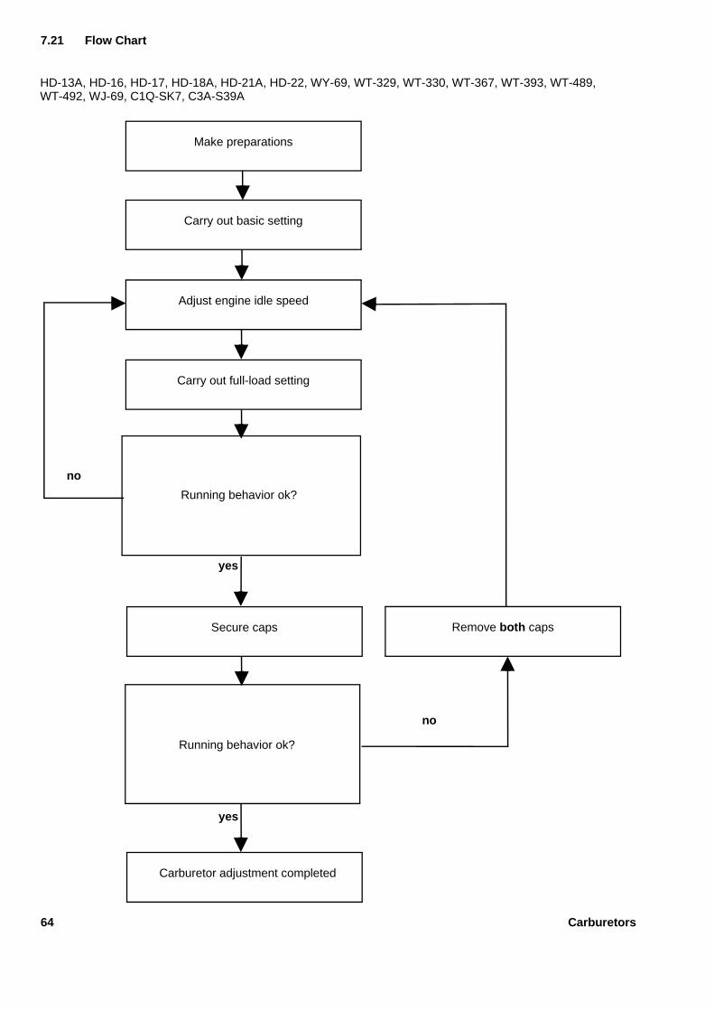
yes
yes
Make preparations
Carry out basic setting
Adjust engine idle speed
Carry out full-load setting
Carburetor adjustment completed
Secure caps Remove both caps
Running behavior ok?
Running behavior ok?
no
no
HD-13A, HD-16, HD-17, HD-18A, HD-21A, HD-22, WY-69, WT-329, WT-330, WT-367, WT-393, WT-489,WT-492, WJ-69, C1Q-SK7, C3A-S39A
7.21 Flow Chart
64 Carburetors
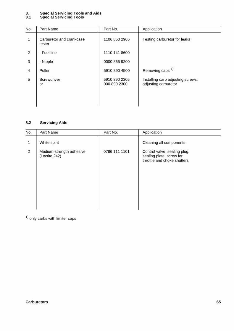
No. Part Name Part No. Application
1 Carburetor and crankcase 1106 850 2905 Testing carburetor for leakstester
2 - Fuel line 1110 141 8600
3 - Nipple 0000 855 9200
4 Puller 5910 890 4500 Removing caps 1)
5 Screwdriver 5910 890 2305 Installing carb adjusting screws,or 000 890 2300 adjusting carburetor
No. Part Name Part No. Application
1 White spirit Cleaning all components
2 Medium-strength adhesive 0786 111 1101 Control valve, sealing plug,(Loctite 242) sealing plate, screw for
throttle and choke shutters
1) only carbs with limiter caps
8.2 Servicing Aids
8. Special Servicing Tools and Aids8.1 Special Servicing Tools
Carburetors 65