STIHL BR 500, 550, 600 - trademachines.com · and Rewind Spring ..... 28 Storing the Machine ......
40
Instruction Manual Notice d’emploi STIH) STIHL BR 500, 550, 600
-
Upload
truongxuyen -
Category
Documents
-
view
218 -
download
1
Transcript of STIHL BR 500, 550, 600 - trademachines.com · and Rewind Spring ..... 28 Storing the Machine ......

Instruction Manual Notice d’emploi
STIH)
STIHL BR 500, 550, 600

1BR 500, BR 550, BR 600
EnglishB
A_
SE
_16
3_
00
4_0
1_
05
.fm
Pri
nte
d o
n c
hlo
rine
-fre
e p
ape
r.P
rintin
g in
ks c
on
tain
ve
ge
tab
le o
ils;
pap
er
can
be
recycle
d.
© A
ND
RE
AS
ST
IHL A
G &
Co.
KG
, 2
00
6
04
58
45
2 8
22
1 D
. M
0,5
. G
6.
PM
. P
rin
ted
in U
SA
STIHl
Contents
Guide to Using this Manual .............. 2
Ignition System ................................. 3
Safety Precautions ........................... 3
Assembling the Blower –
with non-adjustable
blowing attachment ......................... 11
Assembling the Blower –
with length-adjustable
blowing attachment ......................... 15
Adjusting the Throttle Cable ........... 18
Fitting the Harness ......................... 18
4-MIX Engine .................................. 19
Fuel ................................................ 19
Fueling ........................................... 20
Information Before You Start .......... 21
Starting / Stopping the Engine ........ 21
Replacing the Air Filter ................... 24
Motor Management ........................ 25
Adjusting the Carburetor ................ 25
Checking the Spark Plug ................ 27
Spark Arresting Screen
in Muffler ......................................... 28
Replacing Starter Rope
and Rewind Spring ......................... 28
Storing the Machine ........................ 30
Maintenance Chart ......................... 31
Parts and Controls -
with non-adjustable
blowing attachment ......................... 32
Parts and Controls –
with length-adjustable
blowing attachment ......................... 34
Specifications ................................. 36
Special Accessories ....................... 37
Maintenance and Repairs ............... 37
STIHL Limited Emission
Control Warranty Statement ........... 38
Allow only persons who understand this
Manual to operate your blower.
To receive maximum performance and
satisfaction from your STIHL blower, it is
important that you read and understand
the maintenance and safety precautions,
starting on page 3, before using your
blower.
Contact your STIHL dealer or the STIHL
distributor for your area if you do not
understand any of the instructions in this
Manual.
!Warning!
Because a blower is a high-speed tool,
some special safety precautions must
be observed as with any other power
tool to reduce the risk of personal injury.
Careless or improper use may cause
serious or even fatal injury.
STIHL's philosophy is to continually
improve all of its products. As a result,
engineering changes and improvements
are made from time-to-time. If the
operating characteristics or the
appearance of your blower differs from
those described in this Manual, please
contact your STIHL dealer for
information and assistance.
2
English
BR 500, BR 550, BR 600
Pictograms
All the pictograms attached to the
machine are shown and explained in
this manual.
The operating and handling instructions
are supported by illustrations.
Symbols in text
The individual steps or procedures
described in the manual may be marked
in different ways:
: A bullet marks a step or procedure
without direct reference to an
illustration.
A description of a step or procedure that
refers directly to an illustration may
contain item numbers that appear in the
illustration.
Example:
Loosen the screw (1)
Lever (2) ...
In addition to the operating instructions,
this manual may contain paragraphs
that require your special attention. Such
paragraphs are marked with the
symbols described below:
Warning where there is a risk of an
accident or personal injury or
serious damage to property.
Caution where there is a risk of
damaging the machine or its
individual components.
Note or hint which is not essential
for using the machine, but may
improve the operator’s under-
standing of the situation and result
in better use of the machine.
Note or hint on correct procedure in
order to avoid damage to the
environment.
Equipment and features
This instruction manual may refer to
several models with different
features. Components that are not
installed on all models and related
applications are marked with an
asterisk (*). Such components may
be available as special accessories
from your STIHL dealer.
Engineering improvements
STIHL’s philosophy is to continually
improve all of its products. As a result,
engineering changes and improvements
are made from time to time. If the
operating characteristics or the
appearance of your machine differ from
those described in this manual, please
contact your STIHL dealer for
assistance.
Therefore some changes, modifications
and improvements may not be covered
in this manual.
Guide to Using this Manual

3BR 500, BR 550, BR 600
English
!Constant operational readiness
This unit’s ignition system is always
switched on and is only interrupted
briefly to shut down the engine. The
ignition system is switched on again
after engine shutdown. To avoid the
risk of accidents and injury, keep
children away from the unit.
To avoid the risk of fire caused by
ignition sparks outside the cylinder, do
not turn the engine over with the rewind
starter when the spark plug boot is
disconnected or the spark plug removed
from the cylinder.
Warning!
The use of any blower
may be dangerous. It is
important that you read,
fully understand and
observe the following safety
precautions.
!Warning!
Reread the owner`s
manual and the safety
instructions
periodically.
Do not lend or rent your machine without
the owner`s manual.
Be sure that anyone using your unit
understands the information contained
in this manual.
!Warning!
Careless or improper use of the machine
may cause serious injury. Have your
STIHL Dealer show you how to operate
your blower. Observe all applicable
local safety regulations, standards and
ordinances.
!Warning!
Minors should never be allowed to use a
blower. Bystanders, especially children,
and animals should not be allowed in the
area where a machine is in use.
Never let the unit run unattended.
Most of these safety precautions and
warnings apply to the use of all STIHL
blowers. Different models may have
different parts and controls.
See the appropriate section of your
owner`s manual for a description of the
controls and function of the parts of your
machine.
Safe use of a blower involves
1. the operator
2. the blower
3. the use of the blower.
THE OPERATOR
Physical Condition
You must be in good physical condition
and mental health and not under the
influence of any substance (drugs,
alcohol, etc.) which might impair vision,
dexterity or judgment. Do not operate a
blower when you are fatigued.
Be alert - if you get tired while operating
your machine, take a break. Tiredness
may result in loss of control. Working
with any blower can be strenuous. If you
have any condition that might be
aggravated by strenuous work, check
with your doctor before operating the
machine.
Ignition System Safety Precautions

4
English
BR 500, BR 550, BR 600
Your STIHL blower is equipped with an
antivibration system (AV). The AV
system is designed to reduce the
transmission of engine vibrations to the
operator's body. An AV system is
recommended for those operators who
use blowers on a regular or sustained
basis.
Keep the AV system well maintained. A
blower with loose components or with
damaged or worn AV buffers will tend to
have higher vibration levels.
!Warning!
The ignition system of your unit
produces an electromagnetic field of a
very low intensity. This field may
interfere with some pacemakers. To
reduce the risk of serious or fatal injury,
persons with pacemaker should consult
their physician and the pacemaker
manufacturer before operating this tool.
Proper Clothing
!Warning!
To reduce the risk of injury, the operator
should wear proper protective apparel.
Clothing must be sturdy and snug-fitting,
but allow complete freedom of move-
ment.
!Warning!
Avoid loose-fitting jackets,
flared or cuffed pants,
scarfs, unconfined long
hair or anything that could
be drawn into the air
intake.
Good footing is most
important. Wear sturdy
shoes with nonslip soles.
!Warning!
To reduce the risk of injury associated
with the inhalation of dust, use an
appropriate dust respirator for the
material being blown.
!Warning!
Use of this product can generate dust,
mists, and fumes containing chemicals
known to cause respiratory disease,
cancer, birth defects, or other reproduc-
tive harm. If you are unfamiliar with the
risks associated with the particular dust,
mists or fumes at issue, consult your
employer, governmental agencies such
as OSHA and NIOSH and other sources
on hazardous materials. If the substance
being blown or vacuumed is a commer-
cial substance, review the material
safety data sheet for that substance and
/ or consult the material manufacturer /
supplier. The state of California and
some other authorities, for instance,
have published lists of substances
known to cause cancer, reproductive
toxicity, etc.
Control dust, mist and fumes at the
source where possible. In this regard
use good work practices and follow the
recommendations of OSHA / NIOSH
and occupational and trade associa-
tions. When the inhalation of toxic dust,
mists and fumes cannot be eliminated,
the operator and any bystanders should
always wear a respirator approved by
NIOSH / MSHA for the substance at
issue.
5BR 500, BR 550, BR 600
English
!Warning!
Dust with silica in its composition may
contain crystalline silica. Silica is a basic
component of sand, quartz, brick, clay,
granite and numerous other minerals
and rocks, including masonry and con-
crete products. Repeated and / or sub-
stantial inhalation of airborne crystalline
silica can cause serious or fatal respira-
tory disease, including silicosis. In addi-
tion, the state of California and some
other authorities have listed respirable
crystalline silica as a substance known
to cause cancer. When encountering
such materials, always follow the re-
spiratory precautions mentioned above.
!Warning!
Breathing asbestos dust is dangerous
and can cause severe or fatal injury, re-
spiratory illness or cancer. The use and
disposal of asbestos containing products
have been strictly regulated by OSHA
and the Environmental Protection
Agency. Do not blow or disturb asbestos
or asbestos containing products, such
as asbestos insulation. If you have any
reason to believe that you might be
disturbing asbestos, immediately contact
your employer or a local OSHA
representative.
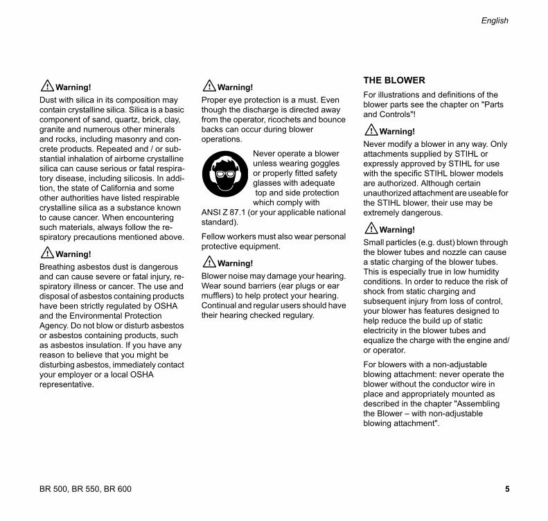
!Warning!
Proper eye protection is a must. Even
though the discharge is directed away
from the operator, ricochets and bounce
backs can occur during blower
operations.
Never operate a blower
unless wearing goggles
or properly fitted safety
glasses with adequate
top and side protection
which comply with
ANSI Z 87.1 (or your applicable national
standard).
Fellow workers must also wear personal
protective equipment.
!Warning!
Blower noise may damage your hearing.
Wear sound barriers (ear plugs or ear
mufflers) to help protect your hearing.
Continual and regular users should have
their hearing checked regulary.
THE BLOWER
For illustrations and definitions of the
blower parts see the chapter on "Parts
and Controls"!
!Warning!
Never modify a blower in any way. Only
attachments supplied by STIHL or
expressly approved by STIHL for use
with the specific STIHL blower models
are authorized. Although certain
unauthorized attachment are useable for
the STIHL blower, their use may be
extremely dangerous.
!Warning!
Small particles (e.g. dust) blown through
the blower tubes and nozzle can cause
a static charging of the blower tubes.
This is especially true in low humidity
conditions. In order to reduce the risk of
shock from static charging and
subsequent injury from loss of control,
your blower has features designed to
help reduce the build up of static
electricity in the blower tubes and
equalize the charge with the engine and/
or operator.
For blowers with a non-adjustable
blowing attachment: never operate the
blower without the conductor wire in
place and appropriately mounted as
described in the chapter "Assembling
the Blower – with non-adjustable
blowing attachment".

6
English
BR 500, BR 550, BR 600
For blowers with an adjustable blowing
attachment only: the control handle is
designed to conduct static electricity
through the throttle cable to the engine
and from the handle through the
operator to the ground. For these units
STIHL offers an optional kit for use in
especially dry and dusty conditions. The
kit contains: (1) blower tubes made with
graphite to help conduct the charge back
to the control handle, and (2) a metal
ring with "wire" for inseration in the end
tube that helps reduce the buildup of
static electricity.
If your blower is properly assembled and
you are still experiencing static shocks,
make sure that your footware has
conductive soles and try operating your
unit without gloves, which may be
interfering with the conduction of the
charge.
THE USE OF THE BLOWER
Transport
Always turn off the engine before taking
the machine off your back and putting it
down. When transporting your unit in a
vehicle, properly secure it to prevent
turnover, fuel spillage and damage to the
machine.
Adjust carrying harness to suit your size
before starting work.
!Warning!
Before starting work, always inspect the
rubber buffers which connect the engine
to the pack frame. If the buffers are torn
or damaged, they should be replaced by
your STIHL dealer. Failure of one or
more buffers may cause the engine or
fuel tank to hit or rub against other parts,
and may lead to serious injury from
increased vibrations or from fire as the
result of fuel leakage.
Fuel
This STIHL unit uses an oil-gasoline
mixture for fuel (see the chapter on
"Fuel" of your owner`s manual).
!Warning!
Gasoline is an extremely
flammable fuel. If spilled
or ignited by a spark or
other ignition source, it
can cause fire and serious
burn injury or property
damage.
!Warning!
To reduce the risk of serious injury from
burns, never attempt to refuel the unit
until it has been completely removed
from the operator.
Use extreme caution when handling
gasoline or fuel mix.
Do not smoke or bring any fire or flame
near the fuel.

7BR 500, BR 550, BR 600
English
Fueling instructions
Fuel your machine in well-ventilated
areas, outdoors only. Always shut off the
engine and allow it to cool before
refueling. Relieve fuel tank pressure by
loosening fuel cap slowly. Never remove
fuel filler cap while engine is running.
Select bare ground for fueling and move
at least 10 feet (3 m) from the fueling
spot before starting the engine. Always
tighten fuel filler cap securely after
fueling. Wipe off any spilled fuel before
starting your blower and check for
leakage.
!Warning!
Check for fuel leakage while refueling
and during operation. If fuel or oil
leakage is found, do not start or run the
engine until leak is fixed and spilled fuel
has been wiped away. Take care not to
get fuel on your clothing. If this happens,
change your clothing immediately.
Always store gasoline in approved
container.
!Warning!
In order to reduce the risk of fuel spillage
and fire from an improperly tightened
fuel cap, correctly position and tighten
the fuel cap in the fuel tank opening.
To do this with this STIHL
cap, raise the grip on the
top of the cap until it is
upright at a 90° angle.
Insert the cap in the fuel
tank opening with the
triangular marks on the grip of the cap
and on the fuel tank opening lining up.
Using the grip, turn the cap firmly
clockwise as far as it will go (approx. a
quarter turn).
Fold the grip flush with the
top of the cap. If the grip
does not lie completely
flush with the cap and the
detent on the grip does
not fit in the
corresponding recess in the filler neck,
the cap is not properly seated and
tightened and you must repeat the
above steps.
Before Starting
!Warning!
Never operate your machine if it is
damaged, improperly adjusted or not
completely and securely assembled.
You should always inspect your unit
before starting it. Make sure the controls
and safety devices are working properly.
!Warning!
To reduce the risk of injury from thrown
parts, check your fanwheel and fan
housing for damage (cracks, nicks,
chipping). If any damage is found, stop
using the unit and contact your STIHL
dealer for repair.
: Throttle trigger must move freely
and spring back to idle position
when released.
: Stop switch must move easily to 0
: Tightness of spark plug boot - if boot
is loose, sparks may occur and
ignite fuel vapor!
: Condition of fanwheel and fan
housing.

8
English
BR 500, BR 550, BR 600
Starting
!Warning!
Your blower is a one-person machine.
To reduce the risk of eye or other injury
from thrown objects, insure that by-
standers are at least 50 feet (15 m)
away during use.
Stop the operation immediately if you
are approached.
For specific starting instructions, see the
appropriate section of your owner`s
manual. Place the machine on firm
ground or other solid surface in an open
area. Maintain good balance and secure
footing.
!Warning!
When you pull the starter grip, don`t
wrap the starter rope around your hand.
Do not allow the grip to snap back, but
guide the starter rope slowly back to
permit the rope to rewind properly.
Failure to follow this procedure may
result in injury to hand or fingers and
may damage the starter mechanism.
The assistance of another person may
be needed in placing the unit on your
back after starting. In order to reduce the
risk of injury to the assistant from thrown
objects or from contact with fumes, the
engine should be kept at idle speed
during this brief period, and your
assistant should not stand in the area of
the outlet nozzle or exhaust. Otherwise,
the unit should be started and operated
without assistance.
!Warning!
To reduce the risk of fire or burn injury,
let the unit cool down before refueling
your blower after use.
!Warning!
Never disassemble or modify your
muffler. The muffler could be damaged
and cause an increase in heat radiation
or sparks, thereby increasing the risk of
fire or burn injury. You may also
permanently damage the engine. Have
your muffler serviced and repaired by
your STIHL Servicing Dealer only.
!Warning!
To reduce the risk of fire or burn injury,
keep the area around the muffler clean.
Remove all debris such as pine needles,
branches or leaves.
!Warning!
An improperly mounted or damaged
cylinder housing or a damaged/
deformed muffler shell may interfere
with the cooling effect of the muffler. To
reduce the risk of fire or burn injury, do
not continue work with a damaged or
improperly mounted cylinder housing or
a damaged/deformed muffler shell.
9BR 500, BR 550, BR 600
English
Working instructions
Work carefully.
When working with the blower, always
wear it on your back using the carrying
harness. Wrap your fingers tightly
around the handle, keeping the control
handle cradled between your thumb and
forefinger. Keep your hand in this
position to have your machine under
control at all times.
Make sure your control handle (and grip
for vacuum attachment) are in good
condition and free of moisture, pitch, oil
or grease.
Operate the blower under good visibility
and daylight conditions only.
!Warning!
Your blower produces
poisonous exhaust fumes
as soon as the
combustion engine is
running. These gases
(e.g. carbon monoxide)
may be color-less and odorless. To
reduce the risk of serious or fatal injury
from breathing toxic fumes, never start
or run the blower indoors or in poorly
ventilated locations. Ensure proper
ventilation when working in trenches or
other confined areas.
Keep the space behind and beside the
engine clear at all times to allow for the
escape of hot and toxic exhaust fumes.
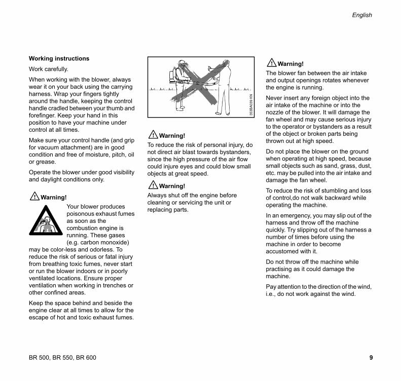
!Warning!
To reduce the risk of personal injury, do
not direct air blast towards bystanders,
since the high pressure of the air flow
could injure eyes and could blow small
objects at great speed.
!Warning!
Always shut off the engine before
cleaning or servicing the unit or
replacing parts.
!Warning!
The blower fan between the air intake
and output openings rotates whenever
the engine is running.
Never insert any foreign object into the
air intake of the machine or into the
nozzle of the blower. It will damage the
fan wheel and may cause serious injury
to the operator or bystanders as a result
of the object or broken parts being
thrown out at high speed.
Do not place the blower on the ground
when operating at high speed, because
small objects such as sand, grass, dust,
etc. may be pulled into the air intake and
damage the fan wheel.
To reduce the risk of stumbling and loss
of control,do not walk backward while
operating the machine.
In an emergency, you may slip out of the
harness and throw off the machine
quickly. Try slipping out of the harness a
number of times before using the
machine in order to become
accustomed with it.
Do not throw off the machine while
practising as it could damage the
machine.
Pay attention to the direction of the wind,
i.e., do not work against the wind.
353B
A039 K
N
10
English
BR 500, BR 550, BR 600
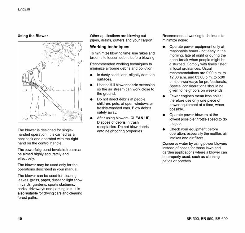
Using the Blower
The blower is designed for single-
handed operation. It is carried as a
backpack and operated with the right
hand on the control handle.
The powerful ground-level airstream can
be aimed highly accurately and
effectively.
The blower may be used only for the
operations described in your manual.
The blower can be used for clearing
leaves, grass, paper, dust and light snow
in yards, gardens, sports stadiums,
parks, driveways and parking lots. It is
also suitable for drying cars and clearing
forest paths.
Other applications are blowing out
pipes, drains, gutters and your carport.
Working techniques
To minimize blowing time, use rakes and
brooms to loosen debris before blowing.
Recommended working techniques to
minimize airborne debris and pollution:
: In dusty conditions, slightly dampen
surfaces.
: Use the full blower nozzle extension
so the air stream can work close to
the ground.
: Do not direct debris at people,
children, pets, at open windows or
freshly-washed cars. Blow debris
safely away.
: After using blowers, CLEAN UP.
Dispose of debris in trash
receptacles. Do not blow debris
onto neighboring properties.
Recommended working techniques to
minimize noise:
: Operate power equipment only at
reasonable hours - not early in the
morning, late at night or during the
noon-break when people might be
disturbed. Comply with times listed
in local ordinances. Usual
recommendations are 9:00 a.m. to
12:00 a.m. and 03:00 p.m. to 5:00
p.m. on workdays for professionals.
Special considerations should be
given to neighbors on weekends.
: Fewer engines mean less noise;
therefore use only one piece of
power equipment at a time, when
possible.
: Operate power blowers at the
lowest possible throttle speed to do
the job.
: Check your equipment before
operation, especially the muffler, air
intakes and air filters.
Conserve water by using power blowers
instead of hoses for those lawn and
garden applications where a blower can
be properly used, such as cleaning
patios or porches.
11BR 500, BR 550, BR 600
English
MAINTENANCE, REPAIR ANDSTORING
Maintenance, replacement, or repair
of the emission control devices and
systems may be performed by any
nonroad engine repair establishment
or individual. However if you claim
warranty for a component which has
not been serviced or maintained pro-
perly or if nonapproved replacement
parts were used, STIHL may deny
warranty.
Use only identical STIHL replacement
parts for maintenance and repair. Use of
parts manufactured by others may
cause serious or fatal injury.
Follow the maintenance and repair
instructions in the appropriate section of
your owner's manual. Refer to the
maintenance chart at the last pages of
this manual.
!Warning!
Always stop the engine and make sure
that the fan is stopped before doing any
maintenance or repair work or cleaning
the blower. Do not attempt any mainten-
ance or repair work not described in your
owner's manual. Have such work
performed at your STIHL servicing
dealer only.
Check fuel filler cap for leaks at regular
intervals. Use the specified spark plug
and make sure it and the ignition lead
are always in good condition.
Tighten all nuts, bolts and screws except
the carburetor adjustment screws after
each use.
!Warning!
A worn or damaged muffler is a fire
hazard and may cause loss of hearing.
Check to see that the muffler is in good
condition. The blower must not be opera-
ted if the muffler is not functioning pro-
perly or has been removed.
Remember that the risk of forest fires is
greater in hot weather. Use the spark
arresting muffler supplied with the unit.
Never touch a hot muffler or burn will
result.
!Warning!
In order to reduce the risk of fire, do not
modify or remove any part of the muffler
or spark arrestor.
Keep spark plug and wire connection
tight and clean. The spark plug electrode
gap should be checked with a feeler
gauge at least every 50 operating hours
and reset if necessary. Fit a new spark
plug if the electrodes are badly pitted.
For any maintenance please refer to the
maintenance chart and to the warranty
statement near the end of this manual.
Store blower in a dry, high or locked
location and out of reach of children.
Before storing for longer than a few
days, always empty the fuel tank.
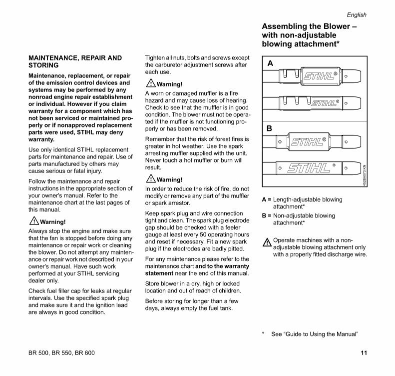
A = Length-adjustable blowing
attachment*
B = Non-adjustable blowing
attachment*
Operate machines with a non-
adjustable blowing attachment only
with a properly fitted discharge wire.
* See “Guide to Using the Manual”
Assembling the Blower –with non-adjustable blowing attachment*
45
2B
A0
73
KN
A
B
12
English
BR 500, BR 550, BR 600
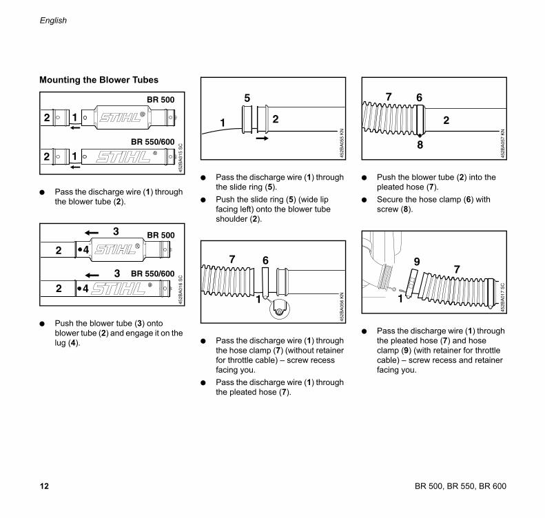
Mounting the Blower Tubes
: Pass the discharge wire (1) through
the blower tube (2).
: Push the blower tube (3) onto
blower tube (2) and engage it on the
lug (4).
: Pass the discharge wire (1) through
the slide ring (5).
: Push the slide ring (5) (wide lip
facing left) onto the blower tube
shoulder (2).
: Pass the discharge wire (1) through
the hose clamp (7) (without retainer
for throttle cable) – screw recess
facing you.
: Pass the discharge wire (1) through
the pleated hose (7).
: Push the blower tube (2) into the
pleated hose (7).
: Secure the hose clamp (6) with
screw (8).
: Pass the discharge wire (1) through
the pleated hose (7) and hose
clamp (9) (with retainer for throttle
cable) – screw recess and retainer
facing you.
452B
A015 S
C452B
A016 S
C
452B
A017 S
C

13BR 500, BR 550, BR 600
English
: Fit the hose clamp (9) on the
pleated hose (7).
: Attach hook (1) of the discharge
wire to the eye (10).
: Push the pleated hose (7) with hose
clamp (9) over the elbow (11) in the
position shown.
: Tighten down the screw (12) firmly.
: Push the nozzle (13) (curved or
straight, depending on market) onto
the blower tube (2) and engage it on
the lug (14).
Operate the machine only with a
properly fitted discharge wire
– The hook on the discharge wire
must be attached to the eye (arrow).
– The sleeve on the discharge wire
must be clipped to the retainer
(arrow).
– The discharge wire must engage
the groove (arrow).
– The discharge wire must project at
least 1 cm.
452B
A060 K
N
79
12
11
452B
A018 S
C
452B
A072 K
N
BR 500
BR 550
BR 600
452B
A071 K
N452B
A046 S
C
min. 1 cm
min. 1/2"

14
English
BR 500, BR 550, BR 600
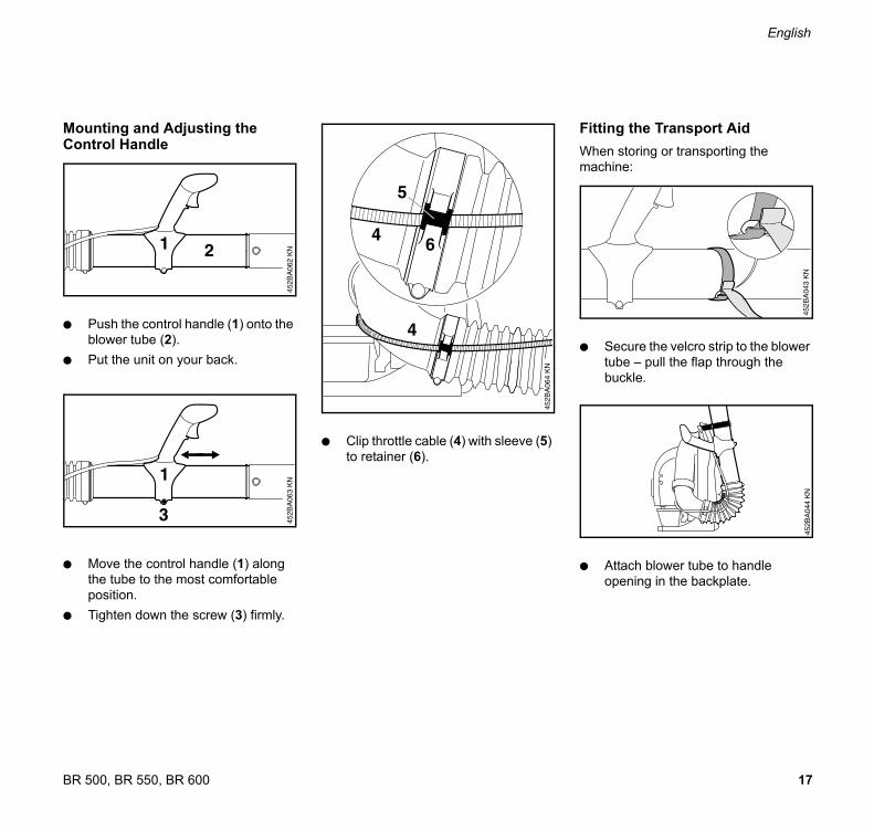
Mounting and Adjusting the Control Handle
: Push the control handle (1) onto the
blower tube (2).
: Put the unit on your back.
: Move the control handle (1) along
the tube to the most comfortable
position.
: Tighten down the screw (3) firmly.
: Clip throttle cable (4) with sleeve (5)
to retainer (6).
Disassembling the Blower Tubes and Control Handle
: Reverse the assembly procedure.
Take care not to damage the
discharge wire during disassembly.
: Rotate the nozzle and blower tubes
to disengage them from the lugs
and then remove them.

15BR 500, BR 550, BR 600
English
Fitting the Transport Aid
When storing or transporting the
machine:
: Secure the velcro strip to the blower
tube – pull the flap through the
buckle.
: Attach blower tube to handle
opening in the backplate.
A = Length-adjustable blowing
attachment*
B = Non-adjustable blowing
attachment*
Machines with a length-adjustable
blowing attachment have no
discharge wire. Any buildup of static
electricity is dissipated via the
conductive control handle.
* See “Guide to Using the Manual”
Mounting the Blower Tubes
BR 500
: Push blower tube (1) onto blower
tube (2) and engage it in one of the
slots (3).
BR 550/600
: Push blower tube (1) onto blower
tube (2) and engage it in one of the
slots (3).
Assembling the Blower –with length-adjustable blowing attachment*
45
2B
A0
73
KN
A
B
452B
A074 K
N
1
2 3
452B
A075 K
N
1
2 3
16
English
BR 500, BR 550, BR 600
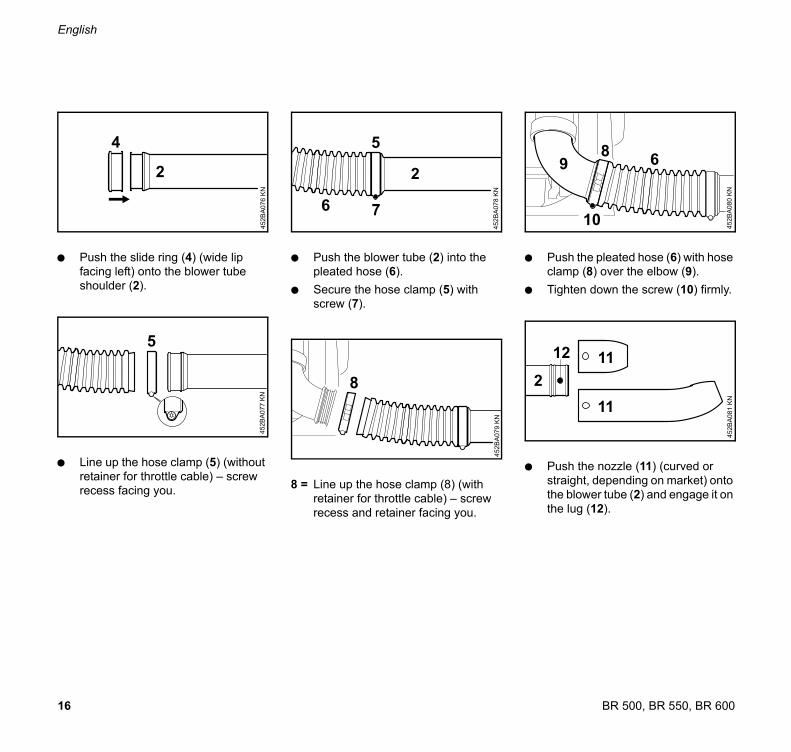
: Push the slide ring (4) (wide lip
facing left) onto the blower tube
shoulder (2).
: Line up the hose clamp (5) (without
retainer for throttle cable) – screw
recess facing you.
: Push the blower tube (2) into the
pleated hose (6).
: Secure the hose clamp (5) with
screw (7).
8 = Line up the hose clamp (8) (with
retainer for throttle cable) – screw
recess and retainer facing you.
: Push the pleated hose (6) with hose
clamp (8) over the elbow (9).
: Tighten down the screw (10) firmly.
: Push the nozzle (11) (curved or
straight, depending on market) onto
the blower tube (2) and engage it on
the lug (12).
452B
A076 K
N
2
4
452B
A077 K
N
5
6
5
452B
A078 K
N
2
7
452B
A079 K
N
8
452B
A080 K
N
68
10
9
2
452B
A081 K
N
11
11
12
17BR 500, BR 550, BR 600
English
Mounting and Adjusting the Control Handle
: Push the control handle (1) onto the
blower tube (2).
: Put the unit on your back.
: Move the control handle (1) along
the tube to the most comfortable
position.
: Tighten down the screw (3) firmly.
: Clip throttle cable (4) with sleeve (5)
to retainer (6).
Fitting the Transport Aid
When storing or transporting the
machine:
: Secure the velcro strip to the blower
tube – pull the flap through the
buckle.
: Attach blower tube to handle
opening in the backplate.

18
English
BR 500, BR 550, BR 600
It may be necessary to correct the
adjustment of the throttle cable after
assembling the blower or after a
prolonged period of operation.
Adjust the throttle cable only when
the machine is completely and
properly assembled.
: Move the throttle trigger to the full
throttle position – as far as stop.
: Turn the screw in the throttle trigger
slowly clockwise until you feel initial
resistance.
: Adjust the harness straps so that
the backplate is held firmly and
comfortably against your back.
A = Adjust height
B = Adjust angle
Tightening the harness straps
: Pull the ends of the straps
downward.
Loosening the harness straps
: Lift the tabs of the two sliding
adjusters.
Adjusting the Throttle Cable Fitting the Harness
373B
A003 K
N373B
A004 K
N
19BR 500, BR 550, BR 600
English
The STIHL 4-MIX engine features
gasoil lubrication and must be run on a
fuel mixture of gasoline and engine oil.
It operates otherwise on the 4-stroke
principle.
This engine is certified to operate on
unleaded gasoline and with the mix ratio
50:1.
Your engine requires a mixture of high-
quality premium gasoline and high-
quality two-stroke air-cooled engine oil.
Use premium branded unleaded
gasoline with a minimum octane rating
of 89 RON.
Note: Models equipped with a catalytic
converter require unleaded gasoline. A
few tankfuls of leaded gasoline can
reduce the efficiency of the catalytic
converter by more than 50%.
Fuel with a lower octane rating may
result in preignition (causing "pinging")
which is accompanied by an increase in
engine temperature. This, in turn,
increases the risk of the piston seizure
and damage to the engine.
The chemical composition of the fuel is
also important. Some fuel additives not
only detrimentally affect elastomers
(carburetor diaphragms, oil seals, fuel
lines etc.), but magnesium castings as
well. This could cause running problems
or even damage the engine. For this
reason it is essential that you use only
high-quality fuels!
Fuels with different percentages of
ethanol are being offered. Ethanol can
affect the running behaviour of the
engine and increase the risk of lean
seizure.
Use only STIHL two-stroke engine oil or
equivalent high-quality two-stroke air-
cooled engine oils for mixing.
We recommend STIHL 50:1 two-stroke
engine oil since it is specially formulated
for use in STIHL engines.
Do not use BIA or TCW (two-stroke
water cooled) mix oils!
Use only STIHL 50:1 heavy-duty
engine oil or an equivalent quality two-
stroke engine oil for the fuel mix in
models equipped with a catalytic
converter.
4-MIX Engine Fuel

20
English
BR 500, BR 550, BR 600
Take care when handling gasoline.
Avoid direct contact with the skin and
avoid inhaling fuel vapour.
The canister should be kept tightly
closed in order to avoid any moisture
getting into the mixture.
The fuel tank and the canister in which
fuel mix is stored should be cleaned
from time to time.
Fuel mix ratio
Only mix sufficient fuel for a few days
work, not to exceed 3 months of storage.
Store in approved safety fuel-canisters
only. When mixing, pour oil into the
canister first, and then add gasoline.
Examples
Dispose of empty mixing-oil canisters
only at authorized disposal locations.
Before fueling, clean the filler cap and
the area around it to ensure that no dirt
falls into the tank.
: Position the machine so that the
filler cap facings up.
In order to reduce the risk of burns
or other personal injury from
escaping gas vapor and fumes,
remove the fuel filler cap carefully
so as to allow any pressure build-up
in the tank to release slowly.
Opening the cap
: Swing the clip outward to upright
position.
: Rotate the cap about 1/4 turn
counterclockwise and remove.
Gasoline Oil (STIHL 50:1 or
equivalent high-quality
oils)
liters liters (ml)
1 0.02 (20)
5 0.10 (100)
10 0.20 (200)
15 0.30 (300)
20 0.40 (400)
25 0.50 (500)
Fueling

21BR 500, BR 550, BR 600
English
Closing the cap
: Place the cap in position – clip
upright – the marks must line up
(see arrows).
: Rotate the cap about 1/4 turn
clockwise.
: Fold the clip down so that it is flush
with the top of the cap.
If the clip does not lie completely flat on
the cap and the lug does not engage the
recess (see arrow), the cap is not
properly closed. You must repeat the
above steps.
Setting lever (1)
Throttle trigger (2)
0 = Engine stop
Ignition is interrupted, the engine
stops. Setting lever does not remain
in this position, it springs back.
# = Run position
Engine runs or can be started.
Throttle trigger can be operated
normally.
C= Lock position
The throttle trigger can be locked in
three positions: 1/3 throttle, 2/3
throttle and full throttle.
To disengage the lock, move the
setting lever back to the normal run
position #
Starting the Engine
Start the machine on a clean and
dust-free patch of ground to ensure
that no dust is sucked in.
: Move the setting lever (1) to #
: Press fuel pump bulb at least five
times – even if the bulb is filled with
fuel.
Information Before You Start
452B
A020 K
N
1
2
Starting / Stopping the Engine
22
English
BR 500, BR 550, BR 600
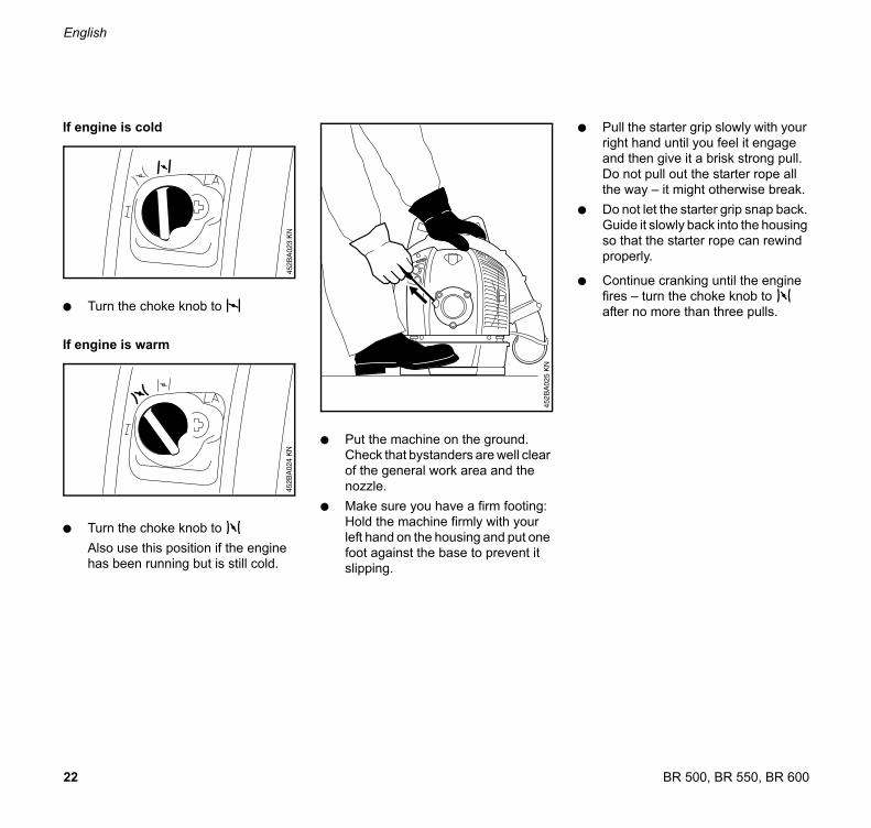
If engine is cold
: Turn the choke knob to l
If engine is warm
: Turn the choke knob to n
Also use this position if the engine
has been running but is still cold.
: Put the machine on the ground.
Check that bystanders are well clear
of the general work area and the
nozzle.
: Make sure you have a firm footing:
Hold the machine firmly with your
left hand on the housing and put one
foot against the base to prevent it
slipping.
: Pull the starter grip slowly with your
right hand until you feel it engage
and then give it a brisk strong pull.
Do not pull out the starter rope all
the way – it might otherwise break.
: Do not let the starter grip snap back.
Guide it slowly back into the housing
so that the starter rope can rewind
properly.
: Continue cranking until the engine
fires – turn the choke knob to n
after no more than three pulls.

23BR 500, BR 550, BR 600
English
When engine begins to fire
If engine is cold:
: Turn choke knob to n and continue
cranking until the engine runs.
If engine is warm:
: Continue cranking until the engine
runs.
When engine runs
To switch to idle speed:
: Blip the throttle trigger (2) – the
choke knob moves automatically to
the run position #
or
: Move the choke knob to the run
position #
At very low outside temperatures
: Open the throttle slightly – warm up
the engine for a short period.
If the engine does not start
If you did not turn the choke knob to n
quickly enough after the engine began to
fire, the combustion chamber is flooded.
: Turn the choke knob to n
: Move the setting lever (1) to C
: Engage the throttle trigger (2) in the
full throttle position.
: Continue cranking until the engine
runs.
24
English
BR 500, BR 550, BR 600
Fuel tank run dry and then refueled
: After refueling, press the fuel pump
bulb at least five times – even if the
bulb is filled with fuel.
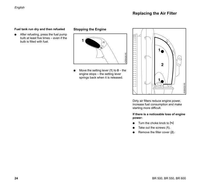
Stopping the Engine
: Move the setting lever (1) to 0 – the
engine stops – the setting lever
springs back when it is released.
Dirty air filters reduce engine power,
increase fuel consumption and make
starting more difficult.
If there is a noticeable loss of engine
power:
: Turn the choke knob to l
: Take out the screws (1).
: Remove the filter cover (2).
452B
A026 K
N
1
Replacing the Air Filter

25BR 500, BR 550, BR 600
English
: Remove the filter element (3) – if it is
dirty or damaged, fit a new element.
: Fit the new filter element in the filter
housing.
: Fit the filter cover.
: Insert and tighten down the screws
firmly.
Exhaust emissions are controlled by the
design of the fundamental engine
parameters and components (e.g.
carburation, ignition, timing and valve or
port timing) without the addition of any
major hardware.
The carburetor comes from the factory
with a standard setting.
This setting provides an optimum fuel-air
mixture under most operating
conditions.
With this carburetor it is only possible to
make corrections to the high speed and
low speed screws within fine limits.
Motor Management Adjusting the Carburetor
H L

26
English
BR 500, BR 550, BR 600
Standard Setting
: Shut off the engine.
: Check the air filter and replace if
necessary.
: Check adjustment of throttle cable
and adjust if necessary – see
"Adjusting the Throttle Cable".
: Check the spark arresting screen* in
the muffler – clean or replace as
necessary.
: Carefully screw both adjusting
screws counterclockwise as far as
stop:
High speed screw (H) is open 3/4
turn.
Low speed screw (L) is open 3/4
turn.
: Start and warm up the engine.
* see "Guide to Using this Manual"
Adjusting Idle Speed
Engine stops while idling
: Turn the idle speed screw (LA)
slowly clockwise until the engine
runs smoothly.
Erratic idling behavior, engine stops
in spite of correction to setting of LA
screw, poor acceleration
Idle setting too lean:
: Turn low speed screw (L)
counterclockwise (no further than
stop) until the engine runs and
accelerates smoothly, but no further
than stop.
Erratic idling behavior
Idle setting too rich:
: Turn low speed screw (L) clockwise
(no further than stop) until the
engine runs and accelerates
smoothly
It is usually necessary to change the
setting of the idle speed screw (LA)
after every correction to the low speed
screw (L).
Fine tuning the carburetor for
operation at high altitude
A slight correction may be necessary if
the engine does not run satisfactorily:
: Check the standard setting.
: Warm up the engine.
: Turn the high speed screw (H)
slightly clockwise (leaner) – no
further than stop.
If the setting is too lean there is
a risk of engine damage due to
insufficient lubrication and
overheating.

27BR 500, BR 550, BR 600
English
Wrong fuel mix (too much engine oil in
the gasoline), a dirty air filter and
unfavorable running conditions (mostly
at part throttle etc.) affect the condition of
the spark plug. These factors cause
deposits to form on the insulator nose
which may result in trouble in operation.
If engine is down on power, difficult to
start or runs poorly at idling speed, first
check the spark plug.
: Remove spark plug
: Clean dirty spark plug.
: Check electrode gap (A) and
readjust if necessary – see
"Specifications".
: Use only resistor type spark plugs
of the approved range.
Rectify problems which have caused
fouling of spark plug:
: Too much oil in fuel mix.
: Dirty air filter.
: Unfavorable running conditions,
e.g. operating at part load.
Fit a new spark plug after approx.
100 operating hours
or earlier if the electrodes are badly
eroded.
To reduce the risk of fire and burn
injury, use only spark plugs
authorized by STIHL. Always press
spark plug boot (2) snugly onto
spark plug terminal (1) of the proper
size. (Note: If terminal has
detachable SAE adapter nut, it must
be attached.)
A loose connection between spark
plug boot and ignition wire
connector in the boot may create
arcing that could ignite combustible
fumes and cause a fire.
Checking the Spark Plug
000B
A002 K
N
1
2
002B
A071 K
N
28
English
BR 500, BR 550, BR 600
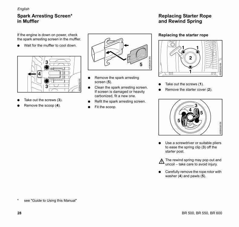
If the engine is down on power, check
the spark arresting screen in the muffler.
: Wait for the muffler to cool down.
: Take out the screws (3).
: Remove the scoop (4).
* see "Guide to Using this Manual"
: Remove the spark arresting
screen (5).
: Clean the spark arresting screen.
If screen is damaged or heavily
carbonized, fit a new one.
: Refit the spark arresting screen.
: Fit the scoop.
Replacing the starter rope
: Take out the screws (1).
: Remove the starter cover (2).
: Use a screwdriver or suitable pliers
to ease the spring clip (3) off the
starter post.
The rewind spring may pop out and
uncoil – take care to avoid injury.
: Carefully remove the rope rotor with
washer (4) and pawls (5).
Spark Arresting Screen*in Muffler
Replacing Starter Rope and Rewind Spring
29BR 500, BR 550, BR 600
English
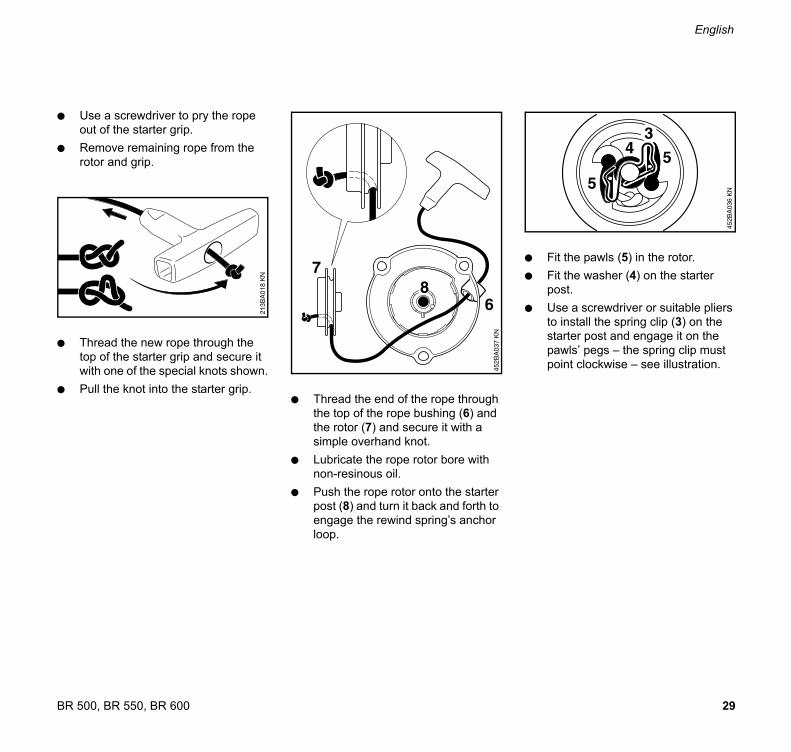
: Use a screwdriver to pry the rope
out of the starter grip.
: Remove remaining rope from the
rotor and grip.
: Thread the new rope through the
top of the starter grip and secure it
with one of the special knots shown.
: Pull the knot into the starter grip. : Thread the end of the rope through
the top of the rope bushing (6) and
the rotor (7) and secure it with a
simple overhand knot.
: Lubricate the rope rotor bore with
non-resinous oil.
: Push the rope rotor onto the starter
post (8) and turn it back and forth to
engage the rewind spring’s anchor
loop.
: Fit the pawls (5) in the rotor.
: Fit the washer (4) on the starter
post.
: Use a screwdriver or suitable pliers
to install the spring clip (3) on the
starter post and engage it on the
pawls’ pegs – the spring clip must
point clockwise – see illustration.
213B
A018 K
N
30
English
BR 500, BR 550, BR 600
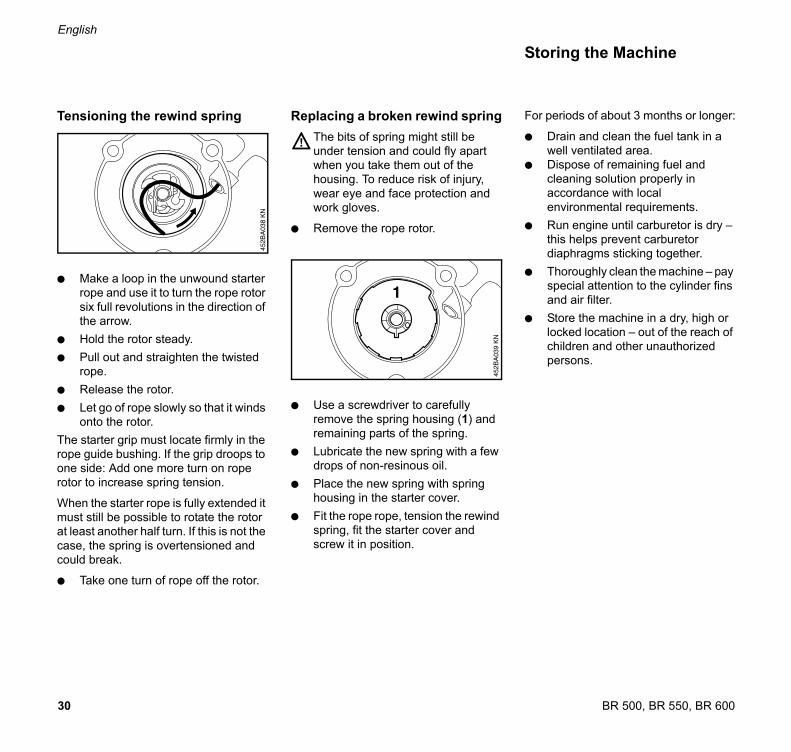
Tensioning the rewind spring
: Make a loop in the unwound starter
rope and use it to turn the rope rotor
six full revolutions in the direction of
the arrow.
: Hold the rotor steady.
: Pull out and straighten the twisted
rope.
: Release the rotor.
: Let go of rope slowly so that it winds
onto the rotor.
The starter grip must locate firmly in the
rope guide bushing. If the grip droops to
one side: Add one more turn on rope
rotor to increase spring tension.
When the starter rope is fully extended it
must still be possible to rotate the rotor
at least another half turn. If this is not the
case, the spring is overtensioned and
could break.
: Take one turn of rope off the rotor.
Replacing a broken rewind spring
The bits of spring might still be
under tension and could fly apart
when you take them out of the
housing. To reduce risk of injury,
wear eye and face protection and
work gloves.
: Remove the rope rotor.
: Use a screwdriver to carefully
remove the spring housing (1) and
remaining parts of the spring.
: Lubricate the new spring with a few
drops of non-resinous oil.
: Place the new spring with spring
housing in the starter cover.
: Fit the rope rope, tension the rewind
spring, fit the starter cover and
screw it in position.
For periods of about 3 months or longer:
: Drain and clean the fuel tank in a
well ventilated area.
: Dispose of remaining fuel and
cleaning solution properly in
accordance with local
environmental requirements.
: Run engine until carburetor is dry –
this helps prevent carburetor
diaphragms sticking together.
: Thoroughly clean the machine – pay
special attention to the cylinder fins
and air filter.
: Store the machine in a dry, high or
locked location – out of the reach of
children and other unauthorized
persons.
Storing the Machine

31BR 500, BR 550, BR 600
English
1) STIHL recommends that this work
be done by a STIHL servicing dealer
Maintenance Chart
The following maintenance intervals apply to normal operating conditions only.If your daily working time is longer than normal or operating conditions are difficult (very dusty work area etc.), shorten the specified intervals accordingly.
be
fore
sta
rtin
g w
ork
afte
r fin
ish
ing
work
or
da
ily
afte
r e
ach
refu
elin
g s
top
wee
kly
mon
thly
every
12
mon
ths
if p
rob
lem
if d
am
ag
ed
if r
equ
ire
d
Complete machineVisual inspection (conditon, leaks) x x
Clean x
Control handle Check operation x x
Air filter Replace x x
Filter in fuel tankHave checked by dealer1) x
Have filter replaced by dealer1) x x
Fuel tank Clean x
CarburetorCheck idle setting x x
Readjust idle x
Spark plugReadjust electrode gap x
Replace after 100 hours of operation
Cooling air intakes Clean x
Valve clearance Check, adjust if necessary, after 139 hours of operation
x
Combustion chamber Decoke after 139 hours of operation, then every 150 hours
x
Spark arresting screen in mufflerCheck x
Clean or replace x
All accessible screws and nuts (not adjusting screws)
Tighten x
Anti-vibration elements (rubber buffers, springs)
Visual inspection x
Have replaced by dealer1) x x
Blower air intake screenCheck x x
Clean x
Throttle cable Adjust x
Discharge wire (machines with non-adjustable blowing attachment)
Check x
Replace x x
Safety labels Replace x

32
English
BR 500, BR 550, BR 600
1 Nozzle, straight*
2 Nozzle, curved*
3 Blower tube BR 550 / 600*
4 Blower tube BR 500*
5 Blower tube BR 500 / 550 / 600
6 Control handle
7 Throttle trigger
8 Setting lever
9 Pleated hose
10 Harness
11 Back plate
12 Intake screen
13 Air Filter Housing
14 Fuel filler cap
15 Spark plug boot
16 Muffler
(with spark arresting screen)*
17 Carburetor adjusting screws
18 Choke knob
19 Fuel pump
20 Starter grip
21 Fuel tank
22 Conductor wire BR 500
23 Conductor wire BR 550 / 600
# = Serial number
* see “Guide to Using this Manual”
Parts and Controls - with non-adjustable blowing attachment
45
2B
A0
70
SC

33BR 500, BR 550, BR 600
English
Definitions
1. Nozzle, Straight
Aims and widens the spray or
airstream.
2. Nozzle, Curved
Aims and widens the spray or
airstream.
3. Blower Tube
Directs airstream.
4. Blower Tube
Directs airstream.
5. Blower Tube
Directs airstream.
6. Control Handle
Handle on the flexible hose to hold
and direct the tube in the required
direction.
7. Throttle Trigger
Controls the speed of the engine.
8. Setting Lever
For run and stop. Sets the trottle to
various positions or stops the
engine.
9. Pleated Hose
For blowing in the desired direction.
10. Harness
For carrying the unit.
11. Backplate
Helps protect the back of the user.
12. Intake Screen
Helps prevent leaves entering
intake.
13. Air Filter Housing
Covers the air filter element.
14. Fuel Filler Cap
For closing the fuel tank.
15. Spark Plug Boot
Connects the spark plug to the
ignition wire.
16. Muffler
(with spark arresting screen)
Attenuates exhaust noises and
diverts exhaust gases away from
operator. The spark arresting
screen is designed to reduce the
risk of fire.
17. Carburetor Adjusting Screws
For tuning carburetor.
18. Choke Knob
Eases engine starting by enriching
mixture.
19. Fuel Pump
Provides extra fuel for cold start.
20. Starter Grip
The grip of the pull starter, which is
the device to start the engine.
21. Fuel Tank
For fuel and oil mixture.
22. Conductor Wire
Helps protect against static
electricity.
23. Conductor Wire
Helps protect against static
electricity.

34
English
BR 500, BR 550, BR 600
1 Nozzle, straight*
2 Nozzle, curved*
3 Blower tube BR 550 / 600*
4 Blower tube BR 500*
5 Blower tube BR 500 / 550 / 600
6 Control handle
7 Throttle trigger
8 Setting lever
9 Pleated hose
10 Harness
11 Back plate
12 Intake screen
13 Air Filter Housing
14 Fuel filler cap
15 Spark plug boot
16 Muffler
(with spark arresting screen)*
17 Carburetor adjusting screws
18 Choke knob
19 Fuel pump
20 Starter grip
21 Fuel tank
# Serial number
* see “Guide to Using this Manual”
Parts and Controls –with length-adjustable blowing attachment*
14
12
13
45
2B
A0
82
KN
1
2
3
4
5
67
8
9
10
11

35BR 500, BR 550, BR 600
English
Definitions
1. Nozzle, Straight
Aims and widens the spray or
airstream.
2. Nozzle, Curved
Aims and widens the spray or
airstream.
3. Blower Tube
Directs airstream.
4. Blower Tube
Directs airstream.
5. Blower Tube
Directs airstream.
6. Control Handle
Handle on the flexible hose to hold
and direct the tube in the required
direction.
Designed to help protect against
static electricity.
7. Throttle Trigger
Controls the speed of the engine.
8. Setting Lever
For run and stop. Sets the trottle to
various positions or stops the
engine.
9. Pleated Hose
For blowing in the desired direction.
10. Harness
For carrying the unit.
11. Backplate
Helps protect the back of the user.
12. Intake Screen
Helps prevent leaves entering
intake.
13. Air Filter Housing
Covers the air filter element.
14. Fuel Filler Cap
For closing the fuel tank.
15. Spark Plug Boot
Connects the spark plug to the
ignition wire.
16. Muffler
(with spark arresting screen)
Attenuates exhaust noises and
diverts exhaust gases away from
operator. The spark arresting
screen is designed to reduce the
risk of fire.
17. Carburetor Adjusting Screws
For tuning carburetor.
18. Choke Knob
Eases engine starting by enriching
mixture.
19. Fuel Pump
Provides extra fuel for cold start.
20. Starter Grip
The grip of the pull starter, which is
the device to start the engine.
21. Fuel Tank
For fuel and oil mixture.

36
English
BR 500, BR 550, BR 600
EPA / CEPA:
The Emission Compliance Period
referred to on the Emissions
Compliance Label indicates the number
of operating hours for which the engine
has been shown to meet Federal
emission requirements.
Category:
A = 300 hours,
B = 125 hours,
C = 50 hours
CARB:
The Emission Compliance Period used on the CARB-Air Index Label indicates the terms: Extended = 300 hours, Intermediate = 125 hours, Moderate = 50 hours
Engine
Ignition System
This spark ignition system meets all
requirements of the Canadian
Interference-Causing Equipment
Regulations ICES-002.
Fuel System
Rewind starter
Starter rope: dia. 3,5 mm x 960 mm
Weights
Maximum air throughput
Air velocity
STIHL 4-MIX Motor
Displacement: 64,8 cm3
Bore: 50 mm
Stroke: 33 mm
Idle speed: 2 500 rpm
Specifications
Type: Electronic
magneto ignition
Spark plug
(suppressed): NGK CMR 6 H
Electrode gap: 0,7 mm
Carburetor: All position
diaphragm
carburetor with
integral fuel
pump
Fuel tank capacity: 1,4 l (1400 cm3)
Fuel mix: see “Fuel”
BR 500: 9,9 kg
BR 550: 9,7 kg
BR 600: 9,5 kg
BR 500: 1 380 m3/h
BR 550: 1 490 m3/h
BR 600: 1 720 m3/h
BR 500: 81 m/s
BR 550: 89 m/s
BR 600: 90 m/s

37BR 500, BR 550, BR 600
English
Lap belt
Straight nozzle*
Curved nozzle*
Contact your STIHL dealer for the latest
information on these and other special
accessories.
* see “Guide to Using this Manual“
Users of this unit should carry out only
the maintenance operations described
in this manual. Other repair work may be
performed only by authorized STIHL
service shops.
Warranty claims following repairs can be
accepted only if the repair has been
performed by an authorized STIHL
servicing dealer using original STIHL
replacement parts.
Original STlHL parts can be identified by
the STlHL part number, the STIHl
logo and, in some cases, by the STlHL
parts symbol (. This symbol may
appear alone on small parts.
Special Accessories Maintenance and Repairs

38
English
BR 500, BR 550, BR 600
Your Warranty Rights and Obligations
STIHL Limited is pleased to explain the
Emission Control System Warranty on
your equipment type engine. In Canada
new 1999 and later model year small off-
road equipment engines must be
designed, built and equipped, at the time
of sale, to meet the U.S. EPA regulations
for small non road engines. The
equipment engine must be free from
defects in materials and workmanship
which cause it to fail to conform with
U.S. EPA standards for the first two
years of engine use from the date of sale
to the ultimate purchaser.
STIHL Limited must warrant the
emission control system on your small
off-road engine for the period of time
listed below provided there has been no
abuse, neglect or improper maintenance
of your small off-road equipment engine.
Your emission control system includes
parts such as the carburetor and the
ignition system. Also included may be
hoses, and connectors and other
emission related assemblies.
Where a warrantable condition exists,
STIHL Limited will repair your small off-
road equipment engine at no cost to you,
including diagnosis (if the diagnostic
work is performed at an authorized
dealer), parts, and labor.
Manufacturer's Warranty Coverage:
In Canada 1999 and later model year
small off-road equipment engines are
warranted for two years. If any emission-
related part on your engine is defective,
the part will be repaired or replaced by
STIHL Limited free of charge.
Owner's Warranty Responsibilities:
As the small off-road equipment engine
owner, you are responsible for the per-
formance of the required maintenance
listed in your owner's manual. STIHL
Limited recommends that you retain all
receipts covering maintenance on your
small off-road equipment engine, but
STIHL Limited cannot deny warranty
solely for the lack of receipts or for your
failure to ensure the performance of all
scheduled maintenance.
Any replacement part or service that is
equivalent in performance and durability
may be used in non-warranty mainten-
ance or repairs, and shall not reduce the
warranty obligations of the engine
manufacturer.
As the small off-road equipment engine
owner, you should be aware, however,
that STIHL Limited may deny you
warranty coverage if your small off-road
equipment engine or a part has failed
due to abuse, neglect, improper
maintenance or unapproved
modifications.
You are responsible for presenting your
small off-road equipment engine to a
STIHL service center as soon as a
problem exists. The warranty repairs will
be completed in a reasonable amount of
time, not to exceed 30 days.
If you have any questions regarding your
warranty rights and responsibilities,
please contact a STIHL customer
service representative at
www.stihl.ca
or you can write to :
STIHL Ltd.,
1515 Sise Road
Box 5666
CA-LONDON ONTARIO; N6A 4L6
Coverage by STIHL Limited
STIHL Limited warrants to the ultimate
purchaser and each subsequent pur-
chaser that your small off-road
equipment engine will be designed, built
and equipped, at the time of sale, to
meet all applicable regulations. STIHL
Limited also warrants to the initial
purchaser and each subsequent
purchaser that your engine is free from
defects in materials and workmanship
which cause the engine to fail to conform
with applicable regulations for a period
of two years.
Warranty Period
The warranty period will begin on the
date the utility equipment engine is
purchased by the initial purchaser and
STIHL Limited Emission Control Warranty StatementThis statement is given voluntarily, based on the MOU (Memorandum ofUnderstanding) as agreed in April 1999 between Environmental Canada and STIHL Limited

39BR 500, BR 550, BR 600
English
you have signed and sent back the war-
ranty card to STIHL Ltd. If any emission
related part on your engine is defective,
the part will be replaced by STIHL
Limited at no cost to the owner.
Any warranted part which is not
scheduled for replacement as required
maintenance, or which is scheduled only
for regular inspection to the effect of
"repair or replace as necessary" will be
warranted for the warranty period. Any
warranted part which is scheduled for
replacement as required maintenance
will be warranted for the period of time
up to the first scheduled replacement
point for that part.
Diagnosis
You, as the owner, shall not be charged
for diagnostic labor which leads to the
determination that a warranted part is
defective. However, if you claim
warranty for a component and the
machine is tested as non-defective,
STIHL Limited will charge you for the
cost of the emission test.
Mechanical diagnostic work will be per-
formed at an authorized STIHL servicing
dealer. Emission test may be performed
either at STIHL Incorporated,
536 Viking Drive, P.O. Box 2015, Virginia
Beach, VA 23452 or at any independent
test laboratory.
Warranty Work
STIHL Limited shall remedy warranty
defects at any authorized STIHL
servicing dealer or warranty station. Any
such work shall be free of charge to the
owner if it is determined that a warranted
part is defective. Any manufacturer-
approved or equivalent replacement part
may be used for any warranty
maintenance or repairs on emission-
related parts and must be provided
without charge to the owner. STIHL
Limited is liable for damages to other
engine components caused by the
failure of a warranted part still under
warranty.
The following list specifically defines the
emission-related warranted parts:
Carburetor
Choke (Cold start enrichment system)
Intake manifold
Air filter
Spark plug
Magneto or electronic ignition system
(ignition module)
Catalytic converter (if applicable)
Fasteners
Where to make a claim for Warranty Service
Bring the product to any authorized
STIHL servicing dealer and present the
signed warranty card.
Maintenance Requirements
The maintenance instructions in this
manual are based on the application of
the recommended 2-stroke fuel-oil
mixture (see also instruction "Fuel").
Deviations from this recommendation
regarding quality and mixing ratio of fuel
and oil may require shorter maintenance
intervals.
Limitations
This Emission Control Systems War-
ranty shall not cover any of the following:
: repair or replacement required
because of misuse, neglect or lack
of required maintenance,
: repairs improperly performed or re-
placements not conforming to
STIHL Limited specifications that
adversely affect performance and/
or durability, and alterations or
modifications not recommended or
approved in writing by STIHL
Limited,
and
: replacement of parts and other
services and adjustments
necessary for required maintenance
at and after the first scheduled
replacement point.