
Sticks and Tissue No 57 August 2011sticksandtissue.yolasite.com/resources/2011/ST57.pdf · Sticks...
62
1 Sticks and Tissue No 57 – August 2011 I’d like to thank all the contributors, without whom this newsletter would not be possible. If you can contribute any articles, wish to make your point of view known etc please send to or phone 01202 625825 [email protected] Thanks to Mark Venter back issues are available for download from http://www.cmac.net.nz/ Writings and opinions expressed are the opinion of the writer but not necessarily the compiler/publisher of Sticks and Tissue. The content does not follow any logical order or set out, it’s “as I receive and put in”. George Stringwell’s Bantam more in article somewhere following
Transcript of Sticks and Tissue No 57 August 2011sticksandtissue.yolasite.com/resources/2011/ST57.pdf · Sticks...

1
Sticks and Tissue No 57 – August 2011
I’d like to thank all the contributors, without whom this newsletter would not be possible.
If you can contribute any articles, wish to make your point of view known etc please send to or phone 01202
625825 [email protected]
Thanks to Mark Venter back issues are available for download from http://www.cmac.net.nz/
Writings and opinions expressed are the opinion of the writer but not necessarily the compiler/publisher of
Sticks and Tissue. The content does not follow any logical order or set out, it’s “as I receive and put in”.
George Stringwell’s Bantam more in article somewhere following

2
From Stephen Winkworth
A couple of items in the latest issue really rang bells for me. I too have a Keil Kraft Ladybird, also, like
David Danvers's model, PAW
powered, but by a .55 BB R/C,
which is quite powerful enough. It
started life with a Heron 1.0cc,
which was too heavy and too
powerful. With the 0.55 our
(whippet-cross) dog 'Dodo' could
just about follow it round the
flying field. So I slightly renamed
it - the 'Lazydodo'.
I'm sorry to see Danvers has
added a separate elevator - this is
is design which cries out for an all-moving tail, based on the original geometry. You don't have to change
anything! However mine does have a removable undercarriage, to enable the whole thing to fit in a carrying
box. By the way, that's a fine garden bench you
have there, David.
You also published a reproduction of an ad for
the Halfax 'Hermes'. This settled a long-running
dispute in my mind. I have one of these, but was
under the impression for a long time that it was a
'Mercury No. 1'. Did Mercury acquire the rights
to the kit from Halfax? Who were Halfax, and
why didn't they have an 'i' where you'd expect to
see one?
My 'Hermes' is the only model I have that I
didn't build. I wonder what happened to the
builder, who used occasionally to appear on
Epsom Downs. He told me, when I bought the Hermes from him in July 1991, that he had originally built
the model for electric power. The radio he fitted
was about the lightest thing you could find in those
days. It came from a Japanese ready-built electric
model, and I bought a spare receiver unit, (see
photo), which I ended up never using. 27 MHz - I
still operate mine with the McGregor tranny in the
photo - it must be 40 years old at least, but it still
works, so why change anything? The carrying box
is my own idea, and was intended to resemble the
kind of box keen modellers used to strap on their
backs when cycling to the Downs.
Happy Flying! Stephen
There have been weeks of intensive study (mainly looking at the model and then looking out of the window
and deciding conditions would really be better for walking the dog). Meticulous engineering refinements
have been effected (see below). Static tests have been held (holding SWAG in winds of various strengths
and noting that the rotors do actually seem to revolve in the intended directions, making gratifyingly fluttery
sounds). Now, at last, the SWAG team has succeeded in achieving controlled flight.
Setting out this morning with SWAG-1b sitting on a bag of tip-bound rubbish on the front seat, relegating
Dolly the dog to the back seat, the team proceeded to the Bar-sur-Loup Club field. Bright sun, a light and
variable wind, and absence of other humans all encouraged optimism. A few practice flights with the dog-

3
exerciser model went according to plan, and Dolly, as chief witness, was duly installed in a shady spot,
securely clipped to her Harrods lead.
There was not enough wind to get the rotors spinning, so they were given a bit of a push (lower
clockwise, upper anti-clock), and SWAG-1b was released onto the tarmac, the propellor of the Anzani
revolving in a leisurely fashion.
A burst of throttle, and she starts to move into the light breeze, rotors continuing to revolve. Advancing
the throttle, she picks up speed. Dispelling fears of a torque-induced tip-over, she continues at a fair pace,
and with throttle all the way forward, is suddenly airborne (total run less than half the 150m of runway). The
climb-out is initially alarmingly steep, so forgetting every warning about the dire influence of negative 'G'
on autogiros, a touch of 'down' elevator is given, and she levels off with no ill effects. Initiate left turn using
rudder. Smooth left turn results. Pleasant whirring sound from rotors. Straighten up, reduce throttle - finally
a more horizontal flight. We are now well above the tops of the neighbouring trees, turning sharply to port.
Definitely more airworthy than the Bleriot, but there is something a little unfamiliar about the way she
moves. Reduce rudder throw, she straightens up crisply. It is time to begin the downwind leg.
She flies, for Chrissake! Loud confirmatory barks from witness Dolly.
This is so good, let's not risk anything. Reduce throttle further, gentle descent. Slow turn to port,
overshoot a touch, straighten up and head for runway. Runway in sight. Reduce throttle a touch more. She's
dead centre. Moment of confusion about correct method of landing autogiros (do they need a burst of
throttle as they touch down? - damn, too late) - she's down, a trifle sharply, but nothing to trouble that
elaborate undercarriage. Rotors still revolving, but for some reason Anzani has stopped dead. Ah, might be
something to do with the transmitter throttle being hard back at 'Stop'.
There she sits, in the middle of the runway, airworthiness proven and totally intact.
Need to digest all this: she's too pretty to risk anything hasty.
The main modifications since first trials (January 18 - shame, shame....) are:
(1) Installation of John Downie engineered rotor hubs: see photo
(2) Increase of rotor blade area - from 26x4cm to 30x5.3cm per blade
(3) Removal of 6mm from top of fin as new rotors now risk hitting it
(4) Rudders offset in the following manner:
To counteract torque:
Tip rudders (which are sharply dihedralled ) - port rudder 4mm to left (down); starbd rudder 6mm left (up).
To address left turn apparent in first 'crash' flight:
Central rudder (main flight control): neutral is offset 6mm to right.
(5) Elevator neutral raised 2mm from flat.
That about sums it up. Celebratory lunch with spouse and 93-year-old mother of absent friends in shady
garden of local posh restaurant, starting with glass of chilled vin rose... but you don't need to hear the rest of
the menu. Whoopee!!!
Photo of SWAG-1b and revamped
Delta 167 follows in next email.

4
Please note important
refinement to Delta: the
laser-grid heat dissipator of
the fusion engine can be
seen in this picture, still
emitting waves of
incandescent muon
particles.
From Jim Wood, Augusta, Maine, USA
Today, Sunday August 31st was my club The Kennebec Valley Model Aviators Annual Picnic And fly in. It
was held at our field in Sidney, Maine. It was sunny 85 degrees/29.5 Celsius, calm winds and unlimited
visibility. Many fights were made, Good food, and a good time was had by all. You can visit us at
www.modelaviators.org
Flight line

5
For the rotor heads Glider tug
Solar powered charge station Stunt wing
Tug and passenger Up and away

6
WW1
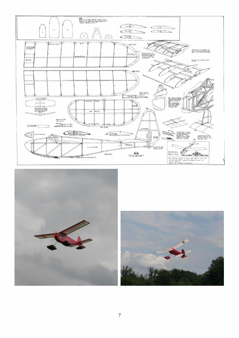
From George Stringwell
Coincidence or what? I see that you had an illustration of the ATO36 glider in the latest Sticks and Tissue.
A few days ago I was moved to dig out the one I built in 1994 from the plan I had just traced to produce a
dyeline master when someone on the Ezone posted a query about the model. Mine had been languishing in
a model box in the barn since we moved to France in 2006. I took some photos to post on the forum, and
thought you might like a couple for S&T. As a result mine has had a couple of hand-glide outings which
show it to be still in good trim, but there are too many trees around here to risk it on tow!
Also attached are a couple of flying shots that Ali, my wife, took yesterday of my Tomboy wearing it's water
boots. I have yet to fly it off water as I am still not QUITE satisfied with the handling and am tweaking the
CG and producing a new fin/rudder with more area and a smaller rudder percentage.
The latest creation, an Albert E Hatfull KK "Bantam" (or "Anzac") is almost complete, so I will hopefully
send you a photo of that before the next issue.
7
8
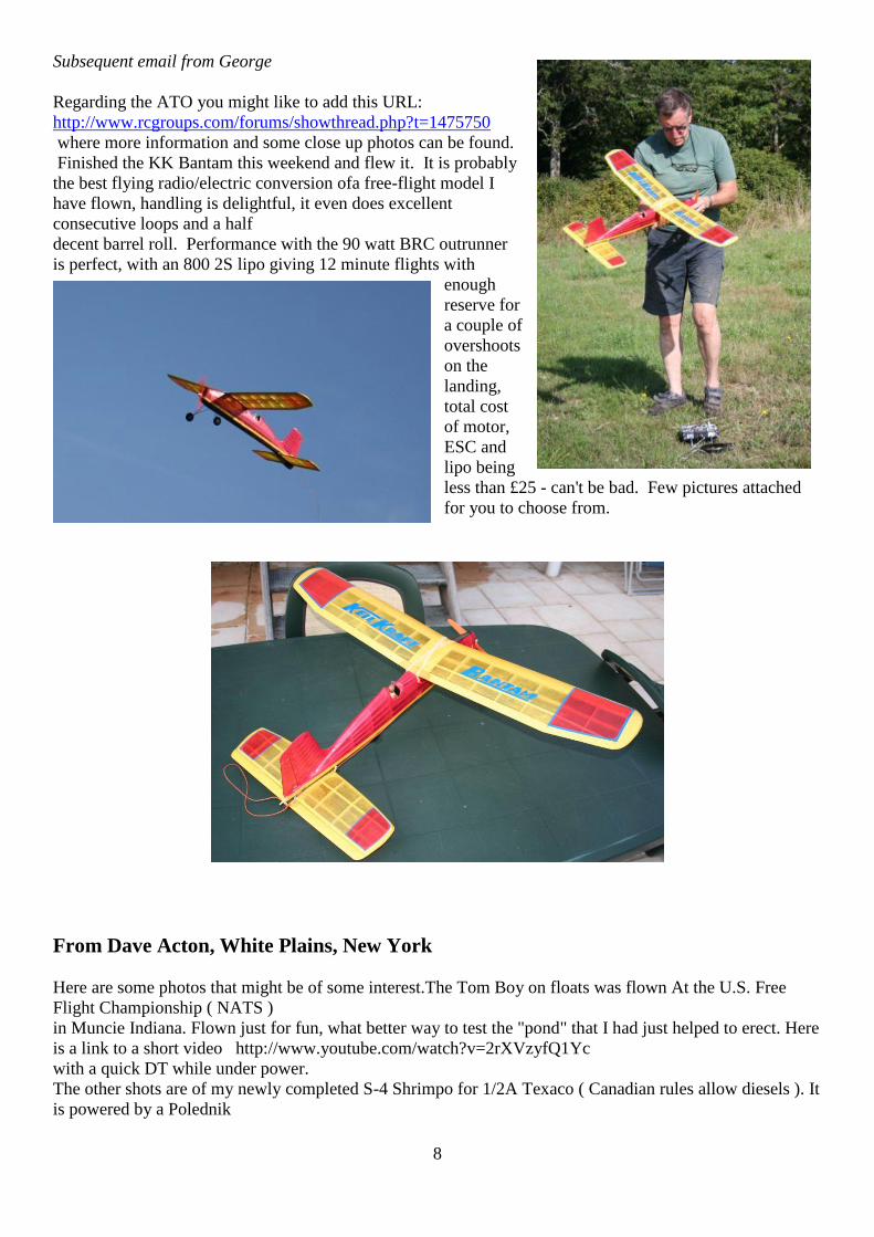
Subsequent email from George
Regarding the ATO you might like to add this URL:
http://www.rcgroups.com/forums/showthread.php?t=1475750
where more information and some close up photos can be found.
Finished the KK Bantam this weekend and flew it. It is probably
the best flying radio/electric conversion ofa free-flight model I
have flown, handling is delightful, it even does excellent
consecutive loops and a half
decent barrel roll. Performance with the 90 watt BRC outrunner
is perfect, with an 800 2S lipo giving 12 minute flights with
enough
reserve for
a couple of
overshoots
on the
landing,
total cost
of motor,
ESC and
lipo being
less than £25 - can't be bad. Few pictures attached
for you to choose from.
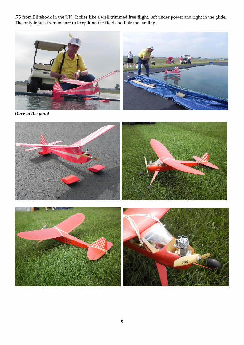
From Dave Acton, White Plains, New York
Here are some photos that might be of some interest.The Tom Boy on floats was flown At the U.S. Free
Flight Championship ( NATS )
in Muncie Indiana. Flown just for fun, what better way to test the "pond" that I had just helped to erect. Here
is a link to a short video http://www.youtube.com/watch?v=2rXVzyfQ1Yc
with a quick DT while under power.
The other shots are of my newly completed S-4 Shrimpo for 1/2A Texaco ( Canadian rules allow diesels ). It
is powered by a Polednik
9
.75 from Flitehook in the UK. It flies like a well trimmed free flight, left under power and right in the glide.
The only inputs from me are to keep it on the field and flair the landing.
Dave at the pond
10
11
12
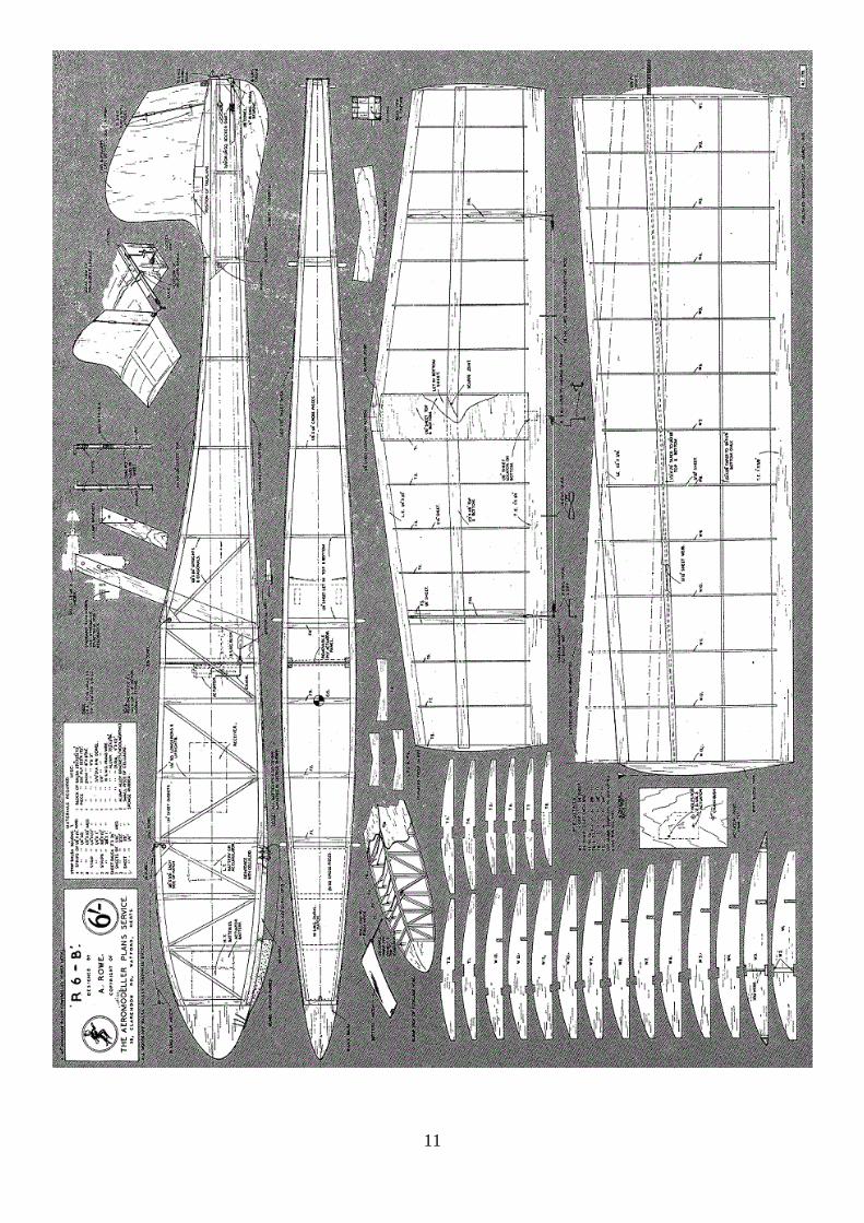
R6-B a 5ft span Functional Radio control design for motors 1.3 cc to 2.5 cc by Allen Rowe from
Aeromodeller March 1955
The most popular model design, flown by the majority of New Zealanders is Allan Rowe’s R6-B., or
variants thereof. Main feature is the mounting of the motor above and behind the trailing edge of the wing.
The advantages of such a setup we leave to Allan himself to explain in the article that follows, and state
without hesitation that it is the most intelligent and practical approach to radio-control model design that we
have yet seen. Over to Allan then:—
This ship, Mark 2 of a sixth series of R/C designs, was built
around the new H.M.V. radio-control equipment and was
intended as a general purpose and unashamedly functional
aeroplane. It will do everything required of a single control R/C
model. It will fly sedately and with precision—it will penetrate
in gusty conditions—at ground level it will give precise control-
line type stunting—with more altitude and a bigger motor it will
do every aerobatic manoeuvre required, including consecutive
barrel rolls—it will outmanoeuvre conventional ships in R/C
combat flying—it will not break propellers—it will not get
messy with oil from the exhaust—it cannot stall under power. It
is an excellent beginner’s model and yet a spectacular expert’s
model—and if any English Aeromodeller has his doubts, I’m
prepared to come over with the original model and prove it—
(provided he pays my fare!). I have no hesitation in stating these
facts because I think it reasonable that any aeroplane designed without left over free flight inhibitions and
specifically for general purpose radio-controlled flying, should have this performance. I do not claim that
R6-B is the answer to such a specification but it is one answer that has proved successful and as such will
perhaps serve to stimulate others to get out of the rut worn by our free-flight ancestors.
In the design stage, the whole conception of a satisfactory aeroplane centred around the need for utterly
reliable radio equipment without which the more spectacular varieties of flying could not be attempted.
This was provided by the new H.M.V. gear which after six months of hard concentrated flying has not yet
been inspected since its original installation in the model. The only servicing it has received has been the
replacement of batteries as required and the winding of the “Relaytor” rubber. The model, now six months
old, has been in the air every week-end as well as frequently during lunch hours and in the evenings after
work.
The need for a strictly functional machine, simple of construction, repair and maintenance influenced
amongst other things the placing of the motor and the absence of conventional undercarriage.
It seemed both an unnecessary and expensive bow to convention to place a valuable engine in the nose
which is normally the point of impact in the event of pilot miscalculation. Furthermore, such a position apart
from ensuring an aeroplane continually messy with exhaust oil, precluded the use of a highly efficient air-
screw (paper-thin highly polished blades are hard work and break easily), increased fuselage drag due to slip
stream velocity, introduced undesirable twisting forces requiring critical thrust-line adjustments and
prevented a clean entry at the most aerodynamically important point of the fuselage. Possible alternative
placings for the motor included the rear of the fuselage and the top of the fin, but the arrangement shown
was finally adopted. Specifically, the advantages of this engine position in actual practice are:
1. The angle at which the motor is set is immaterial because the slipstream has no intruding surface on which
to react. Hence no critical adjustment of thrust-line is required and it is sufficient to
line up the motor by eye.
2. All exhaust oil is blown clear of the model passing over the tailplane and between the fins. As a result, the
model lands in a perfectly clean condition after 30-40 minute flights.
3. Because the slipstream does not have to create drag pushing past obstacles such as wings, fuselage,
engine, etc., all the available thrust is used for its proper purpose. Consequently, big results are obtained
with small capacity engines with a resultant economy of operation. When several hours flying are packed
13
into each afternoon outing, this question of fuel consumption becomes a very real consideration and the
efficient use of a small capacity engine is a useful contribution to overall economy.
As most of our flying in this country is carried out from rough fields, the only justification for the retention
of a conventional undercarriage has been its value (doubtful) as a propeller protector on landing. The skid
finally adopted for R6-B fulfills its function as a landing device but its replacement by a bicycle
undercarriage with wheels inset and the rear wheel say ½” forward of the C.G. would permit take-off from
reasonable ground. R6-B was originally flown with an inverted Mills 1.3 (thinned and polished narrow blade
9’ x 4’) fitted with a 20 minute streamlined tank. In this form and with moderate rudder movement precision
manoeuvres may be carried out with flat skidding turns.
With the same motor, but with maximum rudder deflection, the model becomes moderately acrobatic,
instantaneous control response (and recovery) permitting “ground attack” methods with perfect safety
particularly in view of the model’s non-stall characteristic. In this trop tight turns as low as 3-4 feet from the
ground may be safely performed by the key blipping method (micro switch essential) and recoveries from
wing overs at the same height are also O.K. in reasonable weather. In this trim also, the model has quite a
useful rate of climb and can be used for combat flying or just flying for fun—thermal hunting for the free-
flight boys, cloud chasing, etc. The model’s biggest advantage in combat flying is its ability to “hang on the
prop” in a vertical climb and gradually ease off to its regular climb angle without any stall as speed
diminishes to normal. Thus from a position alongside an opponent a peel off and climb under his tail is
possible without any penalty of lost flying speed.
With full rudder deflection and fitted with an inverted gravity fed FROG 250 (thinned and polished wide
blade l0 x 7), the model is fast, with a rapid rate of climb and is highly aerobatic. For continuous aerobatics a
model must combine a rapid rate of climb with a dean plunging spiral dive which initiates immediately
control is applied and is as near a straight vertical plunge as possible. A tight fluttering spiral or a slow
developing spiral is useless. R6-B combines these desired characteristics and as the gravity fed FROG runs
steadily in all positions, smooth non-Stop aerobatics are possible. A dive of approximately 100—150 feet
gives sufficient speed for consecutive barrel rolls but one turn of spiral dive is usually sufficient for all other
manoeuvres possible by remote control. Combat flying is this trim is not recommended in view of the
increased collision risk due to greater speed and the violent effects of momentary - over control, but if you
like it that way—well go to it.
Prokit-A brief history From Gary I. Davie
Prokit Products first started in 1978 , operating from my father’s model shop Arts.Crafts &
Models,Castleford, West Yorkshire.
I was then 19 and started to manufacture a small range of antique flying models starting with the Buzzard
Bombshell, Dallaire Sportster and other well known classic American models.
Interest in the kits was good enough for me to advertise. Response was only fair at best but gradually the
word spread, sales increased and subsequently I gained considerable interest from other related magazines in
Europe and the USA.
I wasn’t long before I was approached by Ripmax, Irvine, Harry Brooks and others to supply on a wholesale
basis. I declined.

14
Prokit was featured on a number of occasions in Flying Models, RCM Magazine and WW1 Aero. A later
magazine article was featured in Radio Modeler sometime during 1983 which featured the Grumman Duck I
produced.
Response from these articles was considerable, so much so that I had model builders coming to the shop
from all over the country and in particular off the ferry at Hull from Sweden, Norway and Denmark. These
particular modelers always sent letters or phoned in advance to obtain particular supplies in addition to the
kit of their choice.
Mail would arrive from the four corners of the earth sometimes by the dozens. often with International
Money Orders or just Visa Numbers in payment. Many inquiries contained plans, photographs of models
built in the 1930’s and the builders experiences with his creation.
By 1985 sales from Prokit were easily outstripping the shop retail sales. This combined with the early
1980’s recession and miners strike prompted me to move on and continue Prokit as a full time concern.
Prokit Products was then set up at Womersley Hall, Womerseley, Nr Doncaster. Manufacturing continued
full time. Kits were manufactured in batches of 10 or 20 of one design at a time and sent worldwide.
However the logistics of operating a full time business of this nature was at times insurmountable.
I remember sending kits to very remote locations in South Africa, Austrailia, Sri Lanka, Hong Kong. I also
remember sending 2 GHQ Sportsters to Rorkes Drift in South Africa to The Reverend Bob Lowe. He
described the model as being so ugly it was beautiful.
Prokit Products ceased production in 1989 or 1990 and the entire business was mothballed so to speak.
However due to the possibilities of CNC and laser cutting I am now just starting to resurrect the business
under the name ModelKraft.
I have met and corresponded with some fantastic people over those years and sometimes still do. In those
early days I often visited the late David Baker at Muswell Hill who always gave me a great deal of advice. I
gained considerable experience at the 1986 SAM Champs whilst staying with Sal and Nan Taibi
More importantly what always amazed me is the sense or friendship and comradery I experienced within the
world of Antique flying models.
In the words of the late Jim Adams. “The world would be a much better place if more people around the
world took up this hobby today”.

15
If anyone is interested in acquiring any of the old Prokit range of kits please do not hesitate to get in touch. I
still have thousands of parts remaining.
Tel: 07535 449700 or email: [email protected]
Temporary Web Site: microrcmodel.co.uk
16
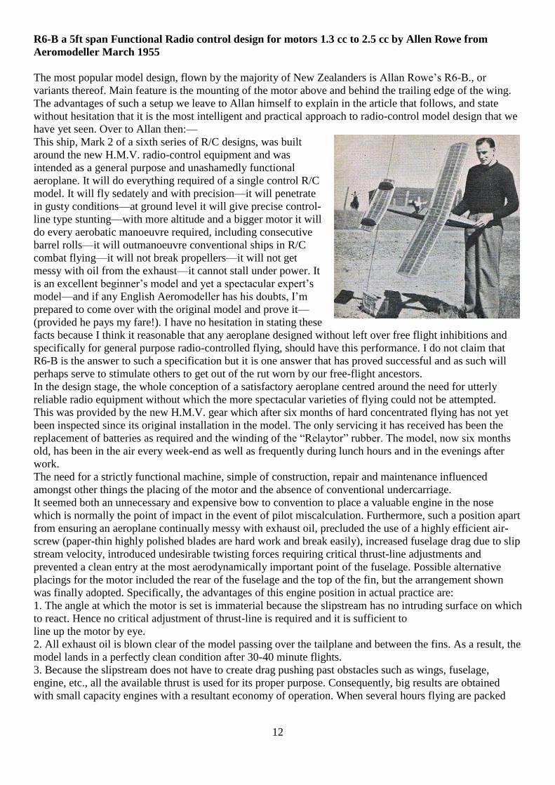
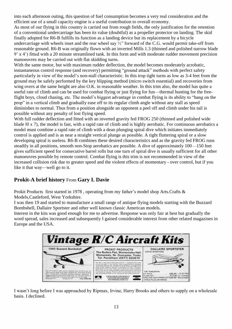
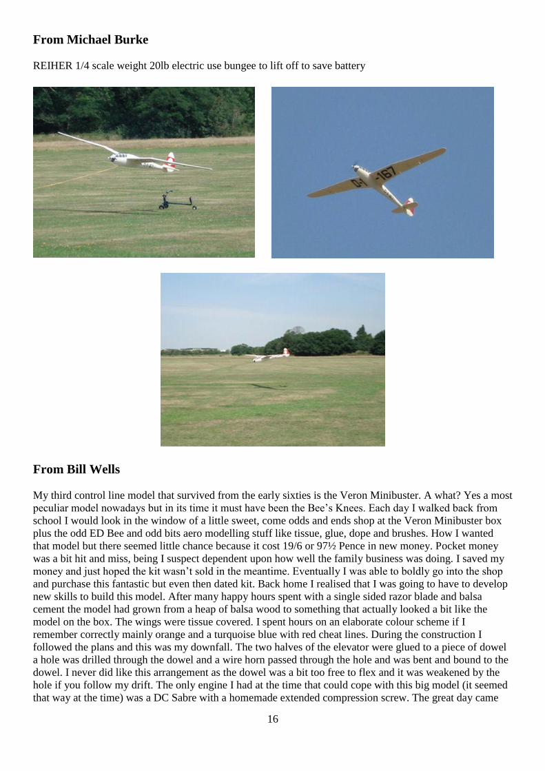
From Michael Burke
REIHER 1/4 scale weight 20lb electric use bungee to lift off to save battery
From Bill Wells
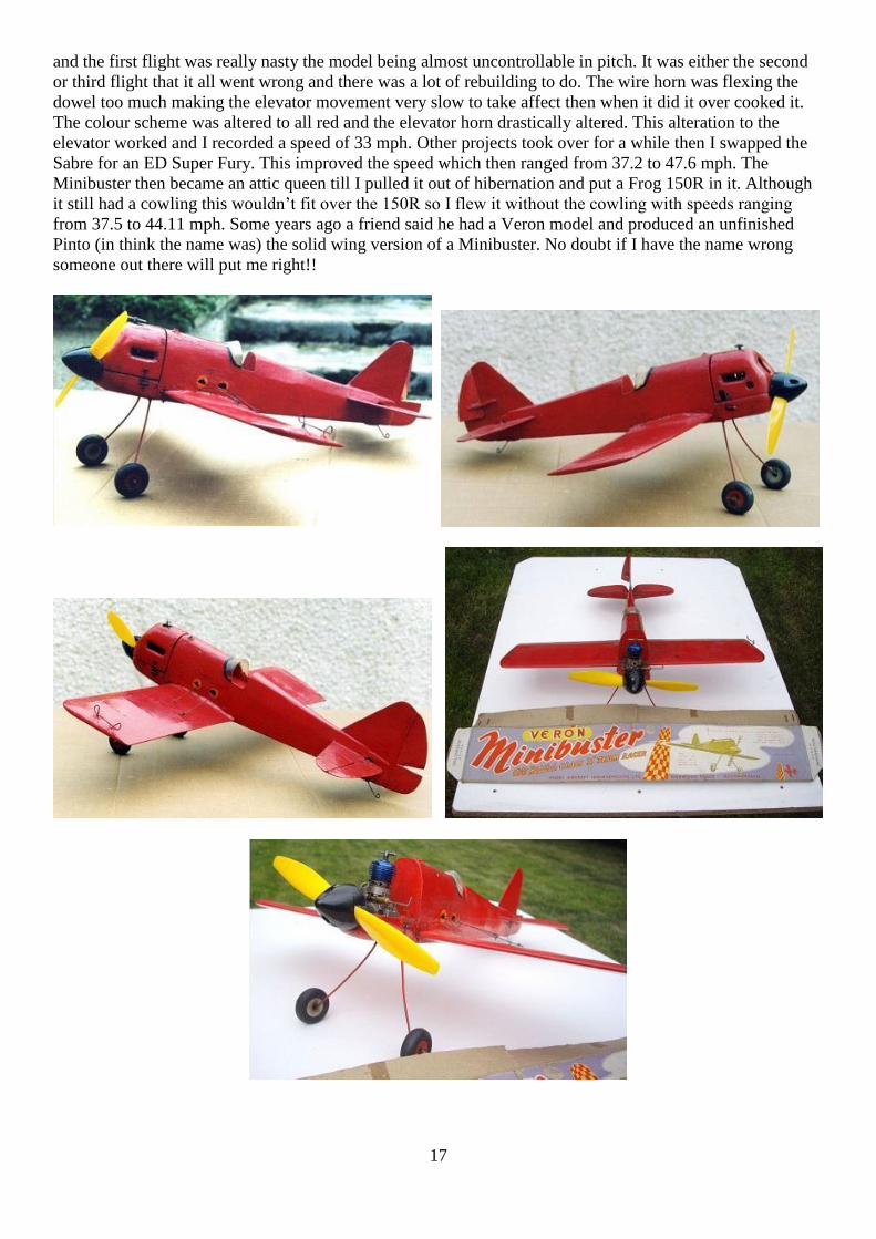
My third control line model that survived from the early sixties is the Veron Minibuster. A what? Yes a most
peculiar model nowadays but in its time it must have been the Bee’s Knees. Each day I walked back from
school I would look in the window of a little sweet, come odds and ends shop at the Veron Minibuster box
plus the odd ED Bee and odd bits aero modelling stuff like tissue, glue, dope and brushes. How I wanted
that model but there seemed little chance because it cost 19/6 or 97½ Pence in new money. Pocket money
was a bit hit and miss, being I suspect dependent upon how well the family business was doing. I saved my
money and just hoped the kit wasn’t sold in the meantime. Eventually I was able to boldly go into the shop
and purchase this fantastic but even then dated kit. Back home I realised that I was going to have to develop
new skills to build this model. After many happy hours spent with a single sided razor blade and balsa
cement the model had grown from a heap of balsa wood to something that actually looked a bit like the
model on the box. The wings were tissue covered. I spent hours on an elaborate colour scheme if I
remember correctly mainly orange and a turquoise blue with red cheat lines. During the construction I
followed the plans and this was my downfall. The two halves of the elevator were glued to a piece of dowel
a hole was drilled through the dowel and a wire horn passed through the hole and was bent and bound to the
dowel. I never did like this arrangement as the dowel was a bit too free to flex and it was weakened by the
hole if you follow my drift. The only engine I had at the time that could cope with this big model (it seemed
that way at the time) was a DC Sabre with a homemade extended compression screw. The great day came
17
and the first flight was really nasty the model being almost uncontrollable in pitch. It was either the second
or third flight that it all went wrong and there was a lot of rebuilding to do. The wire horn was flexing the
dowel too much making the elevator movement very slow to take affect then when it did it over cooked it.
The colour scheme was altered to all red and the elevator horn drastically altered. This alteration to the
elevator worked and I recorded a speed of 33 mph. Other projects took over for a while then I swapped the
Sabre for an ED Super Fury. This improved the speed which then ranged from 37.2 to 47.6 mph. The
Minibuster then became an attic queen till I pulled it out of hibernation and put a Frog 150R in it. Although
it still had a cowling this wouldn’t fit over the 150R so I flew it without the cowling with speeds ranging
from 37.5 to 44.11 mph. Some years ago a friend said he had a Veron model and produced an unfinished
Pinto (in think the name was) the solid wing version of a Minibuster. No doubt if I have the name wrong
someone out there will put me right!!

18
From Bill Grimsley.
I had the good fortune to go to Oshkosh last year and saw the opening off the new model section in the
Museum.
It's full of model aircraft from the very early days right up to the present.
As you know, Oshkosh is the home of the Experimental Aircraft Association, and as was said, all the full
size aircraft builders started building with models. Hence the reason for the Model Museum.
The Museum is fantastic and is ramjam full of historic aircraft, to many to mention and including as you
noted, the Bugatti.
The Airshow its self was attended by by an estimated 17000 aircraft and by day five, I was aeroplaned out!!
What an experience, I would recommend going to everybody.
From Bob Pickernell
A couple of snaps of my latest project, a Veron Streaker. According to the plan title block it is of 1948
vintage , designed by P.L.S, which I assume is Phil Smith. I only had the building plan so had to reproduce
the print wood/dye cut bits.(anyone know if the kit was printwood or dye cut?) This was quite straight
forward, I used Profili Pro to draw the ribs and the fuselage is circular in section so the frames were no
problem. It took a little while to get the stringer positions drawn in on the largest frame. I then scaled the
other frames on a library photo copier. At 5p a throw it was well worth avoiding the bother of drawing up
the bits by hand!

19
Initial trimming was very encouraging but I have yet to use full power. The relatively small size,light weight
and power available from a mills 75 should make for an interesting performance.
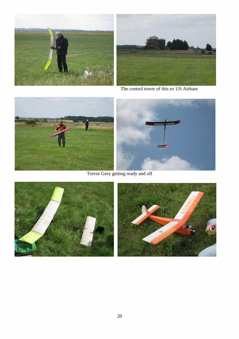
Sculthorpe Sunday 24 July 2011
I’d never been to Sculthorpe or even Norfolk for that matter so it was all of a coincidence when booking a
break I found out about the meet from Bill Longley. It happened that Sculthorpe was just a few miles away
from where we were staying. So the Sunday morning of this two day event I appeared on the scene.
Immediately I recognised a few faces such as David Beales, Martin Dilly and of course Bill Longley.
Not much was flying as there was a strong NW wind so I took a few photos and departed for some
sightseeing. I believe that flying did get underway later on with the Bowden comp certainly being flown.
Daresay there will be more info in SAM Speaks or Clarion.
What a fantastic site for flying FF a large area no shortage of room, in fact miles of it. I felt a bit sorry for
the BMFA team on the entrance gate out in the wind and away from the action if it wasn’t for such
volunteers these events would not happen so a big thank you.
General gist of the line up A small fraction of the flying area.
20
The control tower of this ex US Airbase
Trevor Grey getting ready and off
21
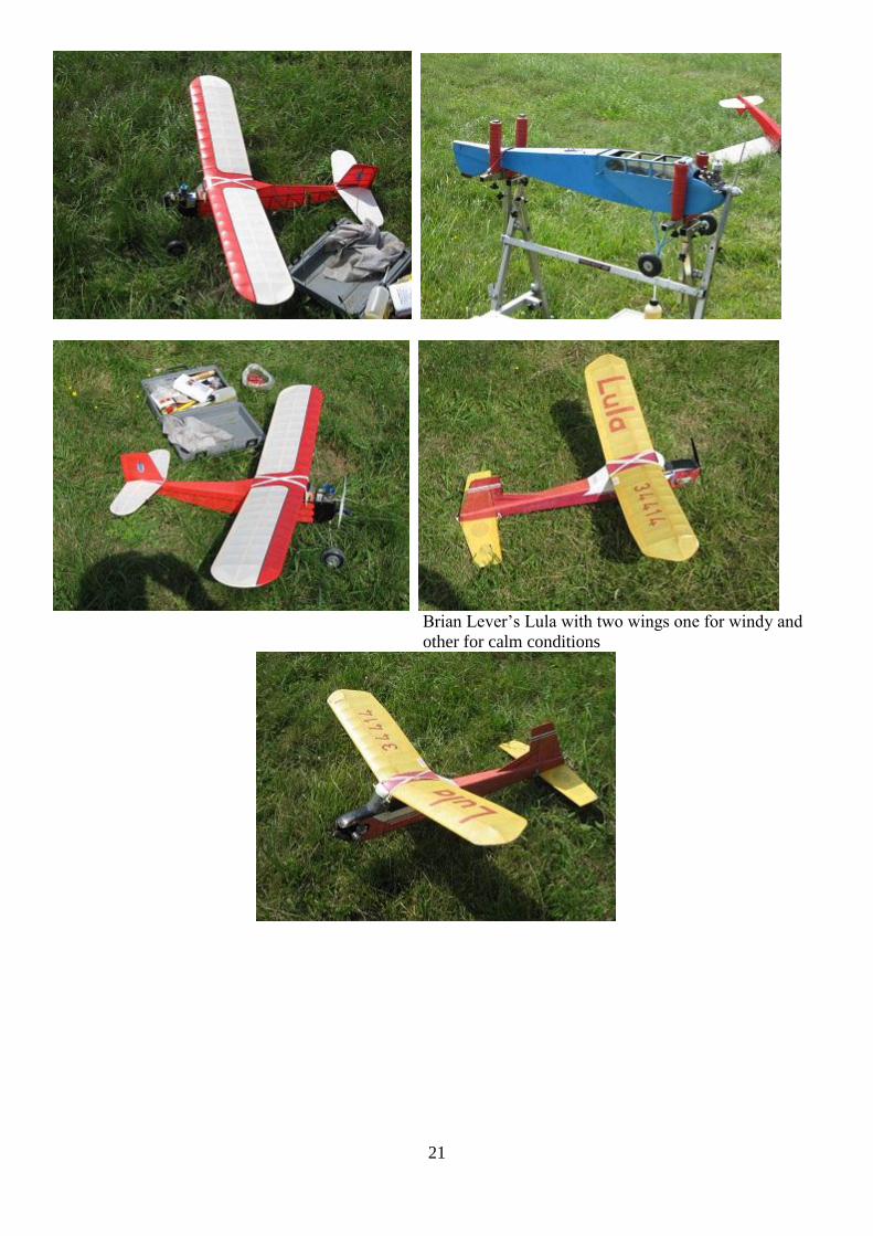
Brian Lever’s Lula with two wings one for windy and
other for calm conditions

22

23
A LIGHTWEIGHT OPEN CLASS SAILPLANE by W. P. Woodrow from Model Aircraft January
1956 48” span
Sailplanes are popular at the R.A.F. Northolt club because many of the members, who are National
Servicemen, cannot afford to fly power models. But on the whole they were building their gliders too
heavily until I demonstrated by designing the Mutant that strength need not be associated with weight
and can be obtained by constructional methods.
Fuselage
Start by cutting K1 from 1/4in. sheet and by binding to it the tow hook. Then cut out formers F1 to F4 and
cement in position to K1. All joints must be pre-cemented to give additional strength. Now cut out F5
and F6 and join together by the lengths of 1/4in x 1/8lin. Make up the auto-rudder mechanism as shown and
cement in position on the struts joining F5 and F6. Cement the whole assembly to K1. Cut out the fuselage
sides from 1/16 in. sheet, taking care only to cut the auto-rudder slot in the port side only. Cut F11 from 1/4
in. sq. Now cement the sides to F1-F6 and the tail ends to F11. Cut out the fin from 1/8 in. sheet; build up
underfin and rudder from two laminations of 1/16 in.
sheet and sandwich the linen hinge between them. Fit
the 1/16 in. ply rudder horn to the rudder. Cut three
lengths of 1/8 in. dowel as shown for wing and tailplane
rubber bands, and cement in position. With strong
twine, tie the auto-rudder line to the lever and cement
the knot. Thread the line down the fuselage and through
the slot on the port side of the fuselage. Cement F7-F10.
Next, cover the top and bottom of fuselage with 1/16
sheet and fit the tail and mainplane platforms, ensuring that the grain of the wood runs as shown on the plan.
Cement the fin into the slots in the top of the fuselage and set in position the under fin and rudder. Connect
up the auto-rudder line temporarily and check for freedom of movement. From a pin make the hook to take
the auto-rudder return band, and cement in place. Carve the nose block roughly from hard balsa and cement
in place and when thoroughly set, finish. Finally, make the dethermaliser peg and cement into F11.
Wings
Cut out 28 ribs W2, and four to the dotted line, also make six of W1. Start by building the centre section.
Shape and pin in position the 1/8in. x 1/2 in. trailing edge. Make up the laminated leading edge from two
strips of 1/8 in. X 3/8 in. and also pin into position. Now cement R1 and R2 in position, ensuring that the
four ribs cut to the dotted line are in the middle of the centre section. Now thoroughly cement in position the
1/16 in. ply dihedral braces at each end of the centre section. When the whole assembly has set, remove
from plane and in a similar manner build up the outer sections ensuring that the inboard rib R1 is set at the
required dihedral angle. ‘When the three sections are completed, once again pin down the centre section and
cement the outer sections to their respective ends and fit the1/8 in. sheet gussets as shown.
Tailplane
Cut out two ribs T1 from 1/16 in. sheet and ten ribs T2 from 1/32 in. sheet. Shape the 1/8 in. X 3/8 in.
trailing edge and pin into place, also the 3/16 in. x 1/4 in. leading edge. Cement the ribs in the positions as
shown and add the tips made from 1/4 in. sheet, and the 1/8 in. sq. spar. Cut out the tip under-fins, but do not
fix them into position at this stage. When the tailpiane has set, remove from plan and shape the leading edge
and tips. Then fit the dethermaliser peg.
Covering and Assembly
Cover the entire model with light weight Modelspan, giving the fuselage three coats of clear dope and after
water shrinking the main and tail-plane surfaces, apply two coats of clear dope. Now cement in position the
tailpiane tip underfins. Connect the auto-rudder line to the rudder horn and adjust the line so that the rudder
is in neutral when the auto-rudder lever is fully forward. Thread a rubber band through a length of neoprene
tubing of sufficient length to prevent the rubber band from turning the rudder from the neutral position when
the lever is fully to the rear. Now hook the rubber band to the hook on the starboard side of the fuselage,
thread it through the neoprene tubing, and secure with thread to the rudder horn.
To get the required turn on the model just cut off pieces of tubing. Fit the tailplane by a rubber band from
one end of the dowel, round the tailplane dethermaliser peg and back to the other end of the dowel, and
24
check the D/T action, and finally secure with a small rubber band around the two D/T pegs. The wings are
held in the usual manner by two strong rubber bands.
Flying
Add weight to the nose between formers F1 and F2 until the c.g., as shown on the plan, is correct. On a calm
day hand launch the model into wind, and a long slow flat glide should be obtained. If the model shows a
tendency to be nose heavy, put packing under the trailing edge of the tailplane until it is corrected.
No more than 1/16 in. will be required. When satisfied with the glide, shorten the neoprene tubing until a
very slight turn to the right is achieved. If a turn is present when the rudder is in neutral, this must be
corrected by either shortening the auto-rudder line if the turn is to the right, or, if to the left, by lengthening
the line and shortening the neoprene tubing until a straight glide is obtained.
Ken de Bomford’s “Incubus” flies again! Chris Rowe in Oz
How it all began!
In mid 2009 Ken de Bomford, my old friend and mentor in the dark arts of aeromodelling, surprised me with
an unexpected gift. It was the Incubus, a beautiful free flight model that was flown by Ken in the Power
Scrambles at the 1957/58 and 1958/59 Australian National Championships.
The Incubus was the last of a series of three similar models that Ken designed and built in the mid 1950’s,
and all three reflected Ken’s lifelong fascination with the sheer beauty, and aerodynamic efficiency of
elliptical wings. Regardless of the efficiency of its wings however, the Incubus with a span of 40” and an all
up weight of 16oz would most certainly have tested the efficiency of its original Mills 0.75 engine! Perhaps
this was the very reason that Ken chose to fly the model in the Power Scrambles, because the last thing that
you needed in such events, was a model that insisted on flying too high, or too far away!
Ken explained that the model had only ever been flown on these two occasions and, following the 1958/59
event, he put the model away in his large model transit box where it had remained ever since! Although
somewhat dusty, the model was complete with its original Mills 0.75 engine and custom twin exhaust
manifold, and remained in remarkably good condition. I had no real idea what I might ultimately do with it,
but a very careful clean up was obviously a good place to start, and the result was real surprise. Thus it was
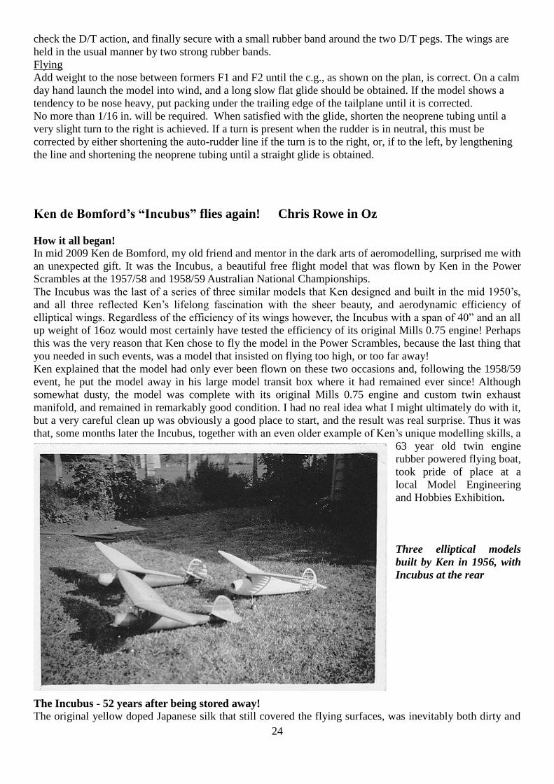
that, some months later the Incubus, together with an even older example of Ken’s unique modelling skills, a
63 year old twin engine
rubber powered flying boat,
took pride of place at a
local Model Engineering
and Hobbies Exhibition.
Three elliptical models
built by Ken in 1956, with
Incubus at the rear
The Incubus - 52 years after being stored away!
The original yellow doped Japanese silk that still covered the flying surfaces, was inevitably both dirty and

25
discoloured, and had long since lost its original tensile strength. The underlying wing, tailplane and fin
structures however, whilst somewhat dry and brittle, remained completely undamaged and as true and solid
as the day they were originally constructed.
The fuselage, a masterpiece of true monocoque construction, with its 1/16’’ balsa planking meticulously
shaped and glued over no less than 14 elliptical formers remained, with the exception of a couple of small
cracks, remained completely undamaged and virtually in original condition. Also covered in yellow
Japanese silk, albeit somewhat faded, the clear doped upper half of the fuselage clearly revealed the
extraordinary craftsmanship evident in the underlying balsa structure. More surprisingly perhaps, when
carefully cleaned of a generous coating of accumulated “gunk”, the lower half of the fuselage was
transformed, with the black and red cellulose automotive lacquer once again recovering its original glossy
lustre.
Last but not least, the engine! As Ken had explained, the little Mills had been purchased specifically for the
Incubus, and the model had only ever been flown in the two Nationals events. It was of course an original
Mills 0.75, that had been barely run in 52 years ago and never started since! I just couldn’t resist; the engine
was carefully cleaned, mounted on a test bench and, with half a dozen flicks, away it went! It reminded me
of that special moment almost 60 years ago, when I started my original Mills 0.75 for the very first time. It
had been ordered from England to replace my ED Bee, which had unfortunately gone missing, some months
previously, whilst mounted in yet another beautiful model built by Ken. That model, a converted sailplane,
had eventually disappeared out of sight in the clouds whilst gliding upwards in endless circles, locked in a
strong Scottsdale thermal. But that of course is another story!
It’s a beautiful old model, but what should I do with it?
Ken was clearly interested in the possibility of the Incubus being restored to flying condition and fitted with
radio control, even suggesting that a change to electric power might be worth considering! For my part,
whilst the possibility of seeing the Incubus fly again certainly intrigued me, I couldn’t help feeling that such
a model should perhaps be treasured in its original state rather than messed about with! After considerable
discussion we eventually agreed however, that because of the obvious technical difficulties, returning the
model to flying condition really did not appear to be a very practical proposition:
At 16onz all up weight (AUW), the original model would most certainly have tested the capacity of
the Mills 0.75 to lift it into the sky. The addition of radio gear would add at least another 4oz and
necessitate the fitting of a more powerful engine, fuel tank and exhaust assembly, all of which would
add a further 3onz or so, resulting in a seriously overweight model with an impossible C/G problem
as well!
The tail end of the model presented its own unique difficulties. The original tailplane and upper fin,
complete with trim tab were attached with rubber bands, not to the top of the rear fuselage but, to a
mounting plate located a quarter of the way up the fin. The lower part of the fin, constructed of ¼”
balsa and strengthened with a King Billy pine spar that extended downwards to form an integral
element of the fuselage structure. It was obviously going to be difficult, to say the least, to create a
rudder large enough to control the model, if the removable elliptical tailplane and elliptical upper fin
assembly were to be preserved in anything approaching their original form!
A more serious complication was that the fully planked fuselage provided no points of internal
access other than, the removable upper half of the cowling and a 30mm circular hole in the top of the
fuselage under the wing. How could modified tail surfaces incorporating elevators and rudder be
connected to servos inside the fuselage, without permanently fixing the tail surfaces in place and
operating the control surfaces with ugly exposed push rods or cables?
Finally, how could a receiver, battery and two servos be successfully installed inside a 55 year old
fully planked fuselage, if internal access to the fuselage was to remain the single existing circular
hole under the wing; a hole hardly big enough to allow you to get two fingers inside?
Somewhat reluctantly, I packed the model away in yet another box, and there it remained for the next 9
months whilst I thought about it!
In October 2010, some six months after Ken’s death, I reopened the box; leaving such a lovely model hidden
26
away unseen was most definitely NOT the right way to treat it. I knew that Ken would have loved to have
seen the Incubus restored once more to flying condition and this, I now resolved, was what I was going to
do.
If the Incubus was to be restored and modified for radio control, she was obviously going to need a rudder
and elevators, and all of the flying surfaces would have to be re-covered. Clearly she was no longer going to
look 52 years old but more like she might have done in 1959, if after the Nationals Ken himself had decided
to modify the model for radio control. Suitable single channel equipment was certainly available at that time,
and control of both rudder and elevators might also have been possible, had Ken decided to opt for a
“Galloping Ghost” system! Finally I knew what I wanted to achieve, and somehow the problems no longer
seemed insurmountable!
I knew what I wanted to do, but how could it be done?
The model had to have a bigger engine or it simply wouldn’t fly, and deep in the dark recesses of my
workshop was a Frog 1.49 Vibramatic diesel that I had purchased new in 1956. Coincidently, like Ken’s
Mills 0.75, it had also remained unused for the last 50 years or so! If the Frog engine, tank and battery, could
all be successfully installed within the original removable upper cowling, the significant increase in weight
forward of the C/G, might perhaps be balanced by installing a micro receiver and servos inside the
removable tailplane and fin structure. Such an arrangement would, in a single stroke, virtually eliminate the
various problems arising from the limited access available to the fuselage, by reducing the internal R/C
requirements to a single lead and switch that would connect the battery at one end, with the receiver and
servos at the other!
With some trepidation I dug out my old Frog engine and compared it with the Mills; I could hardly believe
the result! Not only was it exactly the same height as the Mills but, more significantly, the width of the lower
crankcase was also identical. This meant of course, that the larger Frog engine could be mounted straight
into the original engine bearers, with structural modification being limited to minor changes to the various
openings in the upper cowl!
In a state of mounting enthusiasm, I noted that a new tank could certainly be fitted into the space available
behind the engine; but where on earth could I put the battery? Once again a solution magically appeared!
The bottom half of the radial cowl was formed from a solid block of balsa, and my battery pack just
happened to be a sliding fit between the engine bearers; the battery could be neatly hidden away in a cavity
that I could excavate underneath the engine and tank!
I now had a practical solution for the front end of the model, but could the servos and receiver be fitted
inside the removable tailplane? Examination of the structure confirmed that it had a flat under surface, and a
cambered upper surface approximately 3/8” deep at the centre line. If the structure could be thickened by
about 3mm in the centre section area, it would clearly be possible for two Hitec HS-55 servos and a micro
receiver to be mounted within it; but where would the Incubus balance after such modifications?
After measuring the critical nose and tail moments of the model, and weighing the original engine, the new
engine, and the various components of the R/C system, a simple calculation confirmed that the Incubus
should once again balance correctly; just as long as the tail surfaces could be modified and re-covered
without any significant increase in their weight. Difficult, but not impossible!
The only remaining problem was a niggling concern that the inevitable increase in AUW might seriously
compromise the flight characteristics of the restored model. Whilst there appeared to be no obvious solution,
it occurred to me that whilst the original wheels looked much the same as their modern equivalents, it was
just possible that they were in fact somewhat heavier. A quick de-soldering job followed by another
weighing confirmed, much to my surprise, that by replacing the originals with a pair of Du-Bro Super Lite
wheels, the AUW would be reduced by almost 2onz!
What I actually did!
The front end of the fuselage First, an old fashioned free flight tank was made up to sit on the bearers behind the engine. Although tiny,
the tank contains enough fuel for a two minute engine run; more than enough for a model that will be flown
only on very special occasions. Next, the hole was excavated between the engine bearers to accommodate
the receiver battery, and two indentations in the side of the lower cowling through which the original exhaust
27
pipes had protruded, were filled with scrap balsa. Finally a battery lead was inserted through the firewall
into the cabin area, where it was connected to a new R/C switch mounted high on the fuselage below the
wing seat.
The next step was to modify the removable upper cowl to fit the Frog engine. With the exception of the
opening for the Mills cylinder head, which was simply enlarged to the required new diameter, the various
holes in the cowl were simply filled with scrap balsa and carefully finished to blend with the original cowl
surfaces, both inside and out. New reinforced holes were then provided for the needle valve, tank filling tube
and finger access to the rear induction air intake. This left only the vexed question of how on earth the
exhaust gasses, emitted in all directions from the annular ports of the Frog engine, might be persuaded to
exit the upper cowling in a more orderly fashion!
In my free flight days, diesel engines were almost always left exposed to the elements in order to facilitate
both starting and cooling. This model however had a smart radial cowl with the Mills being equipped with a
custom manifold and twin exhaust pipes! If Ken had managed it in 1957 with the Mills, I felt obliged to do
the same with the Frog engine, but its annular exhaust ports created a real problem, and a workable solution
eluded me for weeks, if not months!
Finally it dawned on me that an exhaust manifold, in the form of a flat rectangular tube, could be made up
from two identical short lengths of aluminium angle. When assembled, it would attach to the engine, and
convert the engine’s annular outlets into a horizontally opposed twin exhaust system, rather like the standard
Frog annular exhaust collector ring available in the 50’s.
Ultimately, it proved quite simple to make. The lower section was drilled for a tight fit on the engine’s
exhaust stack immediately above the crank case gasket; the upper section was similarly drilled, but with a
smaller diameter hole to fit the threaded upper cylinder barrel before being retained by the cylinder head.
After checking for size, shape and fit, the two sections were then placed on the engine with the mating edges
smeared with epoxy, and locked into position by screwing down the cylinder head. Once the epoxy had
cured, and before removal from the engine, the two parts of the manifold were finally joined mechanically
by drilling small holes through each corner and driving in four slightly oversize steel pins. After being
removed, cleaned up and polished, I had a removable twin port exhaust manifold that looks, and even
performs, just like an original part of the engine!
For the upper cowl to remain removable, it was of course necessary for the new manifold to fit completely
inside the cowl. The next step therefore, was to make up two aluminium exhaust stubbs that would butt
against the ends of the manifold and pass through the walls of the cowl on each side. The stubbs were made
up somewhat over length and, in fixing them into the cowl walls, they obviously had to be carefully aligned
with the central manifold. This somewhat challenging task, was eventually achieved by inserting lengths of
soft balsa through the exhaust stubs to lodge in the manifold on each side of the engine. Then with the
engine, upper cowl and exhaust components all temporarily locked in their correct positions, the stubs were
finally epoxied into place.
The tail end of the fuselage
Ultimately, the whole success of the project now hinged on my being able to successfully insert a twin core
battery lead, down through the ply tailplane mount and solid balsa sub-fin; up through the rear fuselage
structure; and out into the cabin area. The visible formers in the cabin area all had large elliptical lightening
holes cut in them, but there was no way of knowing if Ken had followed the same practice with all seven
formers hidden deep inside the rear fuselage. In truth, the only way to find out was to drill the required hole
in the tail end, and hope that he had!
Accordingly, a 1/8” hole was first drilled VERY CAREFULLY, at a 45 degree angle, down through the
original ply tailplane support and the ¼’’ balsa sub-fin structure which supported it, to exit in what I
desperately hoped was an open fuselage structure forward of that point! There followed a lengthy and
extremely frustrating process, at the end of which I had finally managed to insert a length of very thin piano
wire down through the hole I had drilled - around the unavoidable bend into the fuselage – and up into the
cabin area through the seven weight saving holes that Ken had indeed laboriously cut out some 55 years ago.
With that task accomplished, a long battery lead was simply soldered to the tail end of the piano wire and
pulled through into the cabin area, where it was connected to the switch to complete the wiring harness.
Structural modifications to the rear fuselage were now completed with the removal of small sections of the
28
tailplane mount and supporting sub-fin, to provide clearance for the new elevators and rudder, and relocation
of the tailplane retaining dowel to a position forward of the elevator hinge line.
The flying surfaces The next step in the project was to remove the fin from its position on top of the tailplane, so that the
original transfers on the model could be scanned for subsequent reproduction; there was simply no way in
which the originals could have been saved for re-use. With the original silk removed from the wings, it was
immediately obvious that no structural alterations or repairs would be necessary and, following a light
sanding, they were stored away to await re-covering. The fin and tailplane were going to require significant
modification however, and with this in mind accurate plans of the original structures were prepared as the
essential basis for designing the necessary modifications.
The decision as to where the tailplane and fin should be truncated to create the new hinge lines for the
rudder and elevators was more difficult than expected. The original fin, in classic de Bomford fashion, was
fitted with a neat little screw adjustable trim tab, and the obvious solution was to simply extend the original
hinge line downwards to create a larger rudder. Unfortunately that would have resulted in a rudder too small
to provide effective primary control of the model. Accordingly, a completely new hinge line had to be
selected, and a new rear spar inserted into the old structure, suitably reinforced with gussets that matched the
style of the original.
The original trim tab was made up from three laminations of 1/16” balsa, and my replacement rudder just
had to be built the same way! I decided however, that with an engine double the capacity of the original
Mills, it would be prudent to also increase the area of the fin; the original in my view, being already
somewhat on the small size. Accordingly I decided to increase the fin area by about 15%, by simply
extending the original elliptical outline, and structure, downwards to increase both the height and area of that
part of the fin and rudder that were mounted above the tailplane.
Having already determined the position of the new elevator hinge line, the original tailplane structure was
pinned down on my scratch plan, and the central and adjacent ribs removed together with the section of
original trailing edge that was to be replaced by the elevators. The outboard ribs were shortened and a new
rear spar inserted on the hinge line, together with strengthening gussets. The centre section was rebuilt with
ribs of increased height to accommodate the two servos to be mounted flush with the lower tailplane surface.
The original K/B spar was of course retained, but the height was increased by adding balsa packing to its top
edge. The new centre section was then sheeted top and bottom with 1/16” balsa, and balsa packing strips
were also glued to the tops of all outboard ribs and spar to systematically increase their height. When dry the
balsa packing was carefully sanded back to result in a rebuilt tailplane some 3mm thicker at the centre
section tapering uniformly to the original thickness around the elliptical leading and trailing edges. As in the
case of the rudder, the new elevators were fabricated from three laminations of 1/16” balsa, and attached
with standard micro hinges.
Underneath the tailplane, a compartment in front of the spar was created to accommodate the micro receiver,
which is retained in place with a press fit balsa cover. Behind the spar, balsa mounting blocks glued between
the top and bottom sheeting, provide for retention of the two servos. A simply push fit into place, the servos
are retained in position in flight by the rubber bands that hold the fin and tailplane assembly in place on the
original ply tailplane support. Two small dowels in the underside of the tailplane, lock into corresponding
holes in the tailplane seat to ensure continued alignment of the fin and rudder.
Covering and finishing
With the structural modifications completed, it remained to recover the flying surfaces and touch up the
paintwork as necessary. Before re-covering however, I decided to wipe over the open balsa structures with a
rag soaked in a Baltic Pine coloured water based wood stain. This resulted in both the old and new balsa
elements immediately assuming a satisfyingly uniform pale golden colour with absolutely no increase in
weight, whilst providing a perfect colour base for the yellow Lite Span that I had decided to use.
This was the first time that I had used Lite Span, and the end result was better than I could possibly have
hoped for. Fortuitously, yellow Lite Span turned out to be virtually identical in colour, and texture, to an
unused sheet of the original Japanese silk that Ken had also carefully put away and kept in his workshop for
more than 50 years! Better still, the trick with the Baltic Pine wood stain has worked a treat, by rendering the

29
various alterations that have been made to the fin and tailplane, largely indistinguishable from the adjacent
original structure. The last step was of course to apply the new transfers, reproduced from my digital images
of the originals by Signfast Pty Ltd in Hobart.
Finishing the fuselage was not a big task! The black engine bay and surrounding cowl were re-finished with
enamel that closely matched the adjacent original black laquer on the fuselage; and a couple of tiny cracks in
the red area were touched up, using a $2 bottle of perfectly matching nail varnish that I just happened to
notice at my local chemist shop one day.
Finally the Incubus was ready to fly again!
The Incubus flies again!
Flying any model for the first time is a somewhat nerve racking business, but the prospect of flying this
particular model for the first time simply terrified me! Of course I could have been sensible, and asked
someone with more flying experience to handle the test flight, but somehow I felt that I owed it to Ken to do
the whole thing myself. So it was that in perfect weather conditions, on 7 April 2011, I finally plucked up
the courage to fly the Incubus for the first time.
The first flight was almost, but not quite, as difficult as I had imagined it might have been! After the hand
launch, the Incubus soared away but immediately demonstrated a barely controllable tendency to turn
sharply to the left and drop her wing as an obvious consequence of the increased power and torque of the
Frog engine. Unfortunately, with no engine control, I had no choice but to spend most of the flight
desperately trying to avert disaster, whilst fervently hoping that the engine would stop immediately, if not
sooner! Finally she transitioned into a nice flat glide and, with a sense of considerable relief I was able to
land her safely back in the centre of the grass strip!
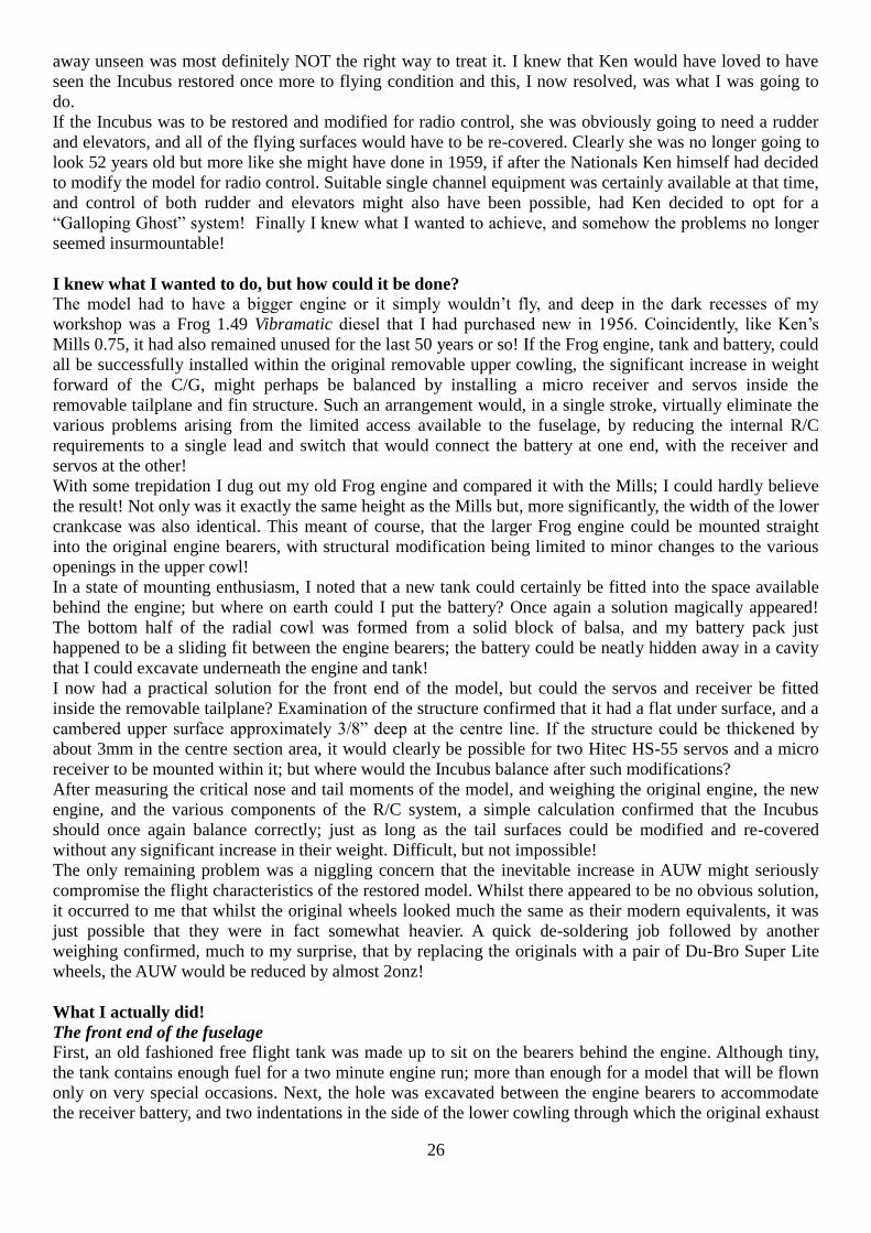
Back on the workbench I was fortunate in being able to increase the engine side thrust without any need for
structural alteration, and the model was next flown on 27 May 2011 with Peter Ralph in attendance with his
camera to do justice to the occasion. This time the model behaved impeccably, as may clearly be seen in
Peter’s superb shots of the model in flight.
Conclusion
This project proved both uniquely challenging and immensely satisfying in that I finally achieved exactly
what I had hoped for. The Incubus now appears just as she might have done in 1959, had Ken himself
modified her for radio control. Most importantly however, whenever and wherever she may be flown in the
future, she will I am sure continue to provide an appropriate reminder of the truly unique contribution that
Ken de Bomford made to aeromodelling in Australia.
Safe and steady
30
After 52 years, the Incubus flies again!
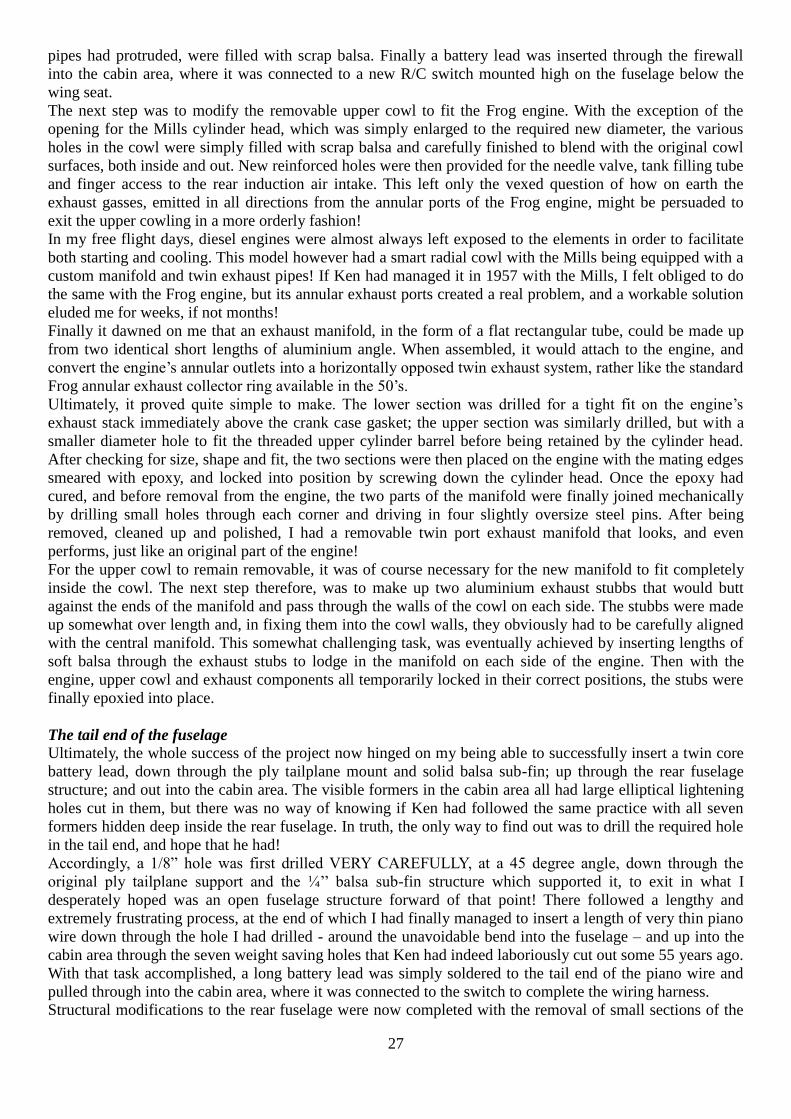
Chris Rowe with the restored Incubus

31
Everything in place but the upper cowling
Frog 1.49 with its new three part exhaust manifold
and modified upper cow
Just perfect!
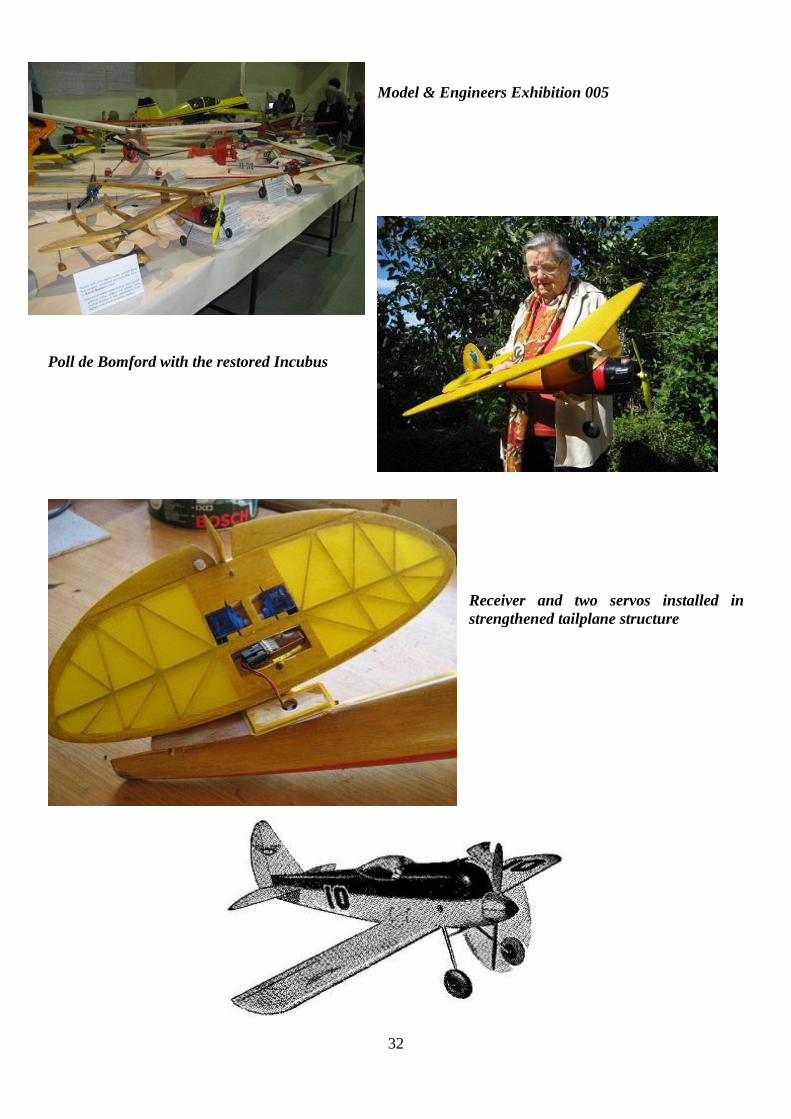
32
Model & Engineers Exhibition 005
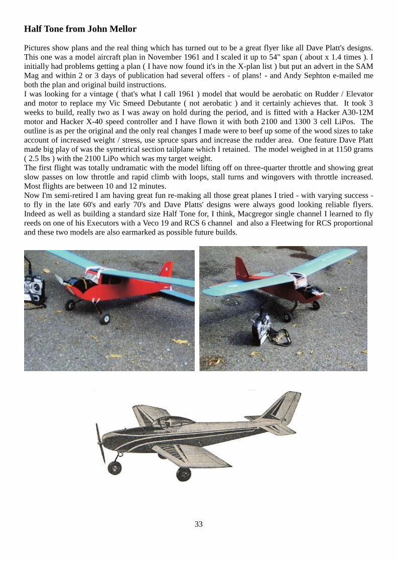
Poll de Bomford with the restored Incubus
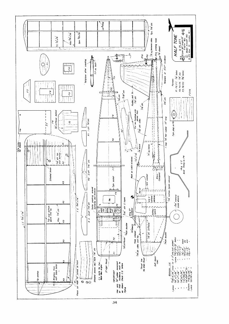
Receiver and two servos installed in
strengthened tailplane structure
33
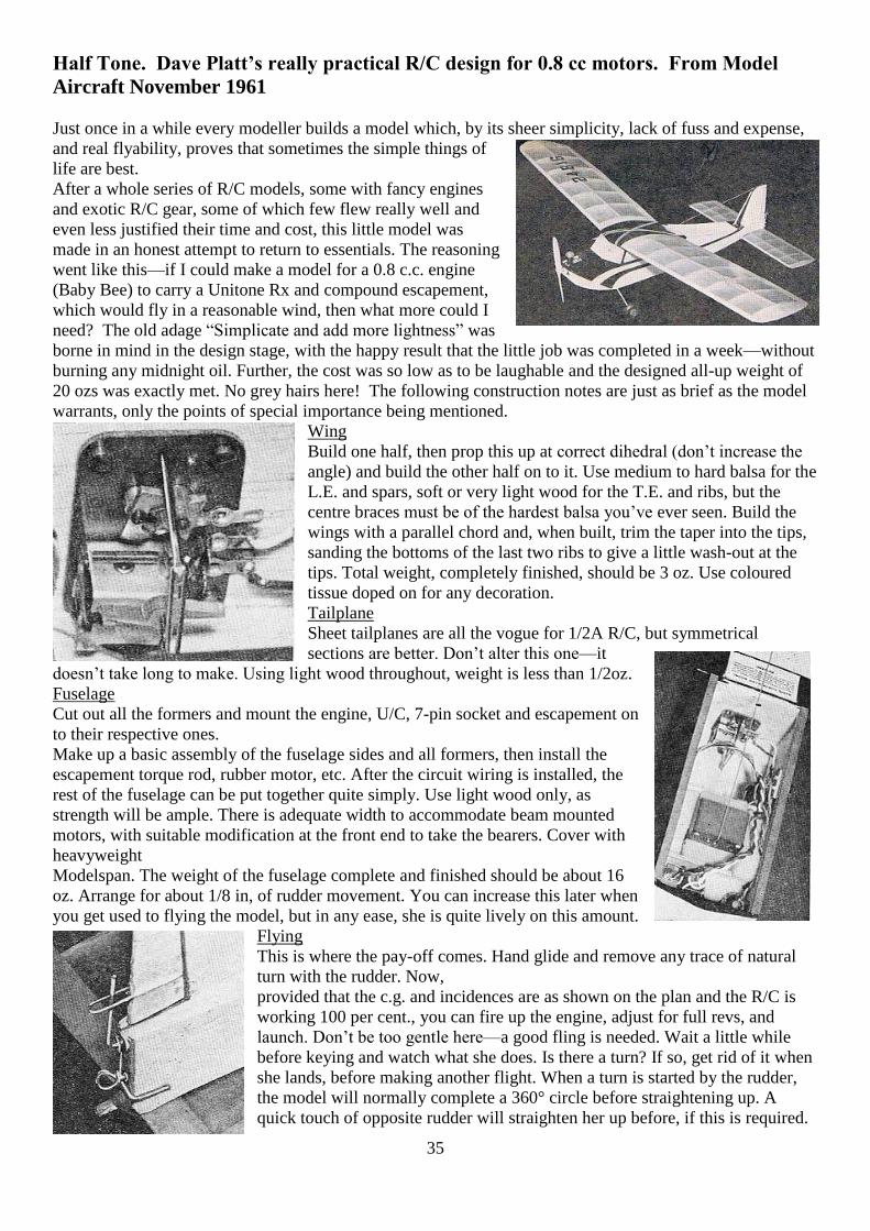
Half Tone from John Mellor
Pictures show plans and the real thing which has turned out to be a great flyer like all Dave Platt's designs.
This one was a model aircraft plan in November 1961 and I scaled it up to 54" span ( about x 1.4 times ). I
initially had problems getting a plan ( I have now found it's in the X-plan list ) but put an advert in the SAM
Mag and within 2 or 3 days of publication had several offers - of plans! - and Andy Sephton e-mailed me
both the plan and original build instructions.
I was looking for a vintage ( that's what I call 1961 ) model that would be aerobatic on Rudder / Elevator
and motor to replace my Vic Smeed Debutante ( not aerobatic ) and it certainly achieves that. It took 3
weeks to build, really two as I was away on hold during the period, and is fitted with a Hacker A30-12M
motor and Hacker X-40 speed controller and I have flown it with both 2100 and 1300 3 cell LiPos. The
outline is as per the original and the only real changes I made were to beef up some of the wood sizes to take
account of increased weight / stress, use spruce spars and increase the rudder area. One feature Dave Platt
made big play of was the symetrical section tailplane which I retained. The model weighed in at 1150 grams
( 2.5 lbs ) with the 2100 LiPo which was my target weight.
The first flight was totally undramatic with the model lifting off on three-quarter throttle and showing great
slow passes on low throttle and rapid climb with loops, stall turns and wingovers with throttle increased.
Most flights are between 10 and 12 minutes.
Now I'm semi-retired I am having great fun re-making all those great planes I tried - with varying success -
to fly in the late 60's and early 70's and Dave Platts' designs were always good looking reliable flyers.
Indeed as well as building a standard size Half Tone for, I think, Macgregor single channel I learned to fly
reeds on one of his Executors with a Veco 19 and RCS 6 channel and also a Fleetwing for RCS proportional
and these two models are also earmarked as possible future builds.
34
35
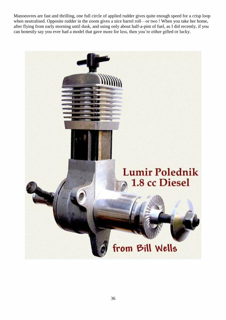
Half Tone. Dave Platt’s really practical R/C design for 0.8 cc motors. From Model
Aircraft November 1961
Just once in a while every modeller builds a model which, by its sheer simplicity, lack of fuss and expense,
and real flyability, proves that sometimes the simple things of
life are best.
After a whole series of R/C models, some with fancy engines
and exotic R/C gear, some of which few flew really well and
even less justified their time and cost, this little model was
made in an honest attempt to return to essentials. The reasoning
went like this—if I could make a model for a 0.8 c.c. engine
(Baby Bee) to carry a Unitone Rx and compound escapement,
which would fly in a reasonable wind, then what more could I
need? The old adage “Simplicate and add more lightness” was
borne in mind in the design stage, with the happy result that the little job was completed in a week—without
burning any midnight oil. Further, the cost was so low as to be laughable and the designed all-up weight of
20 ozs was exactly met. No grey hairs here! The following construction notes are just as brief as the model
warrants, only the points of special importance being mentioned.
Wing
Build one half, then prop this up at correct dihedral (don’t increase the
angle) and build the other half on to it. Use medium to hard balsa for the
L.E. and spars, soft or very light wood for the T.E. and ribs, but the
centre braces must be of the hardest balsa you’ve ever seen. Build the
wings with a parallel chord and, when built, trim the taper into the tips,
sanding the bottoms of the last two ribs to give a little wash-out at the
tips. Total weight, completely finished, should be 3 oz. Use coloured
tissue doped on for any decoration.
Tailplane
Sheet tailplanes are all the vogue for 1/2A R/C, but symmetrical
sections are better. Don’t alter this one—it
doesn’t take long to make. Using light wood throughout, weight is less than 1/2oz.
Fuselage
Cut out all the formers and mount the engine, U/C, 7-pin socket and escapement on
to their respective ones.
Make up a basic assembly of the fuselage sides and all formers, then install the
escapement torque rod, rubber motor, etc. After the circuit wiring is installed, the
rest of the fuselage can be put together quite simply. Use light wood only, as
strength will be ample. There is adequate width to accommodate beam mounted
motors, with suitable modification at the front end to take the bearers. Cover with
heavyweight
Modelspan. The weight of the fuselage complete and finished should be about 16
oz. Arrange for about 1/8 in, of rudder movement. You can increase this later when
you get used to flying the model, but in any ease, she is quite lively on this amount.
Flying
This is where the pay-off comes. Hand glide and remove any trace of natural
turn with the rudder. Now,
provided that the c.g. and incidences are as shown on the plan and the R/C is
working 100 per cent., you can fire up the engine, adjust for full revs, and
launch. Don’t be too gentle here—a good fling is needed. Wait a little while
before keying and watch what she does. Is there a turn? If so, get rid of it when
she lands, before making another flight. When a turn is started by the rudder,
the model will normally complete a 360° circle before straightening up. A
quick touch of opposite rudder will straighten her up before, if this is required.
36
Manoeuvres are fast and thrilling, one full circle of applied rudder gives quite enough speed for a crisp loop
when neutralised. Opposite rudder in the zoom gives a nice barrel roll—or two ! When you take her home,
after flying from early morning until dusk, and using only about half-a-pint of fuel, as I did recently, if you
can honestly say you ever had a model that gave more for less, then you’re either gifted or lucky.
37
38
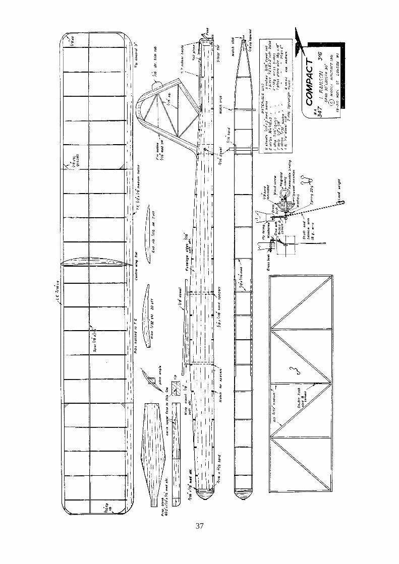
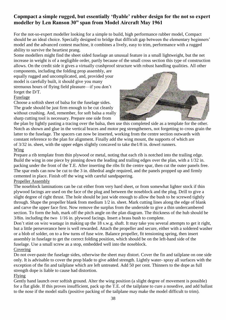
Copmpact a simple rugged, but essentially ‘flyable’ rubber design for the not so expert
modeller by Len Ranson 30” span from Model Aircraft May 1961
For the not-so-expert modeller looking for a simple to build, high performance rubber model, Compact
should be an ideal choice. Specially designed to bridge that difficult gap between the elementary beginners’
model and the advanced contest machine, it combines a lively, easy to trim, performance with a rugged
ability to survive the heartiest prang.
Some modellers might find the sheet sided fuselage an unusual feature in a small lightweight, but the net
increase in weight is of a negligible order, partly because of the small cross section this type of construction
allows. On the credit side it gives a virtually crashproof structure with robust handling qualities. All other
components, including the folding prop assembly, are
equally rugged and uncomplicated, and, provided your
model is carefully built, it should give you many
strenuous hours of flying field pleasure—if you don’t
forget the D/T.
Fuselage
Choose a softish sheet of balsa for the fuselage sides.
The grade should be just firm enough to be cut cleanly
without crushing. And, remember, for soft balsa a really
sharp cutting tool is necessary. Prepare one side from
the plan by lightly pasting a tracing over the balsa, then use this completed side as a template for the other.
Notch as shown and glue in the vertical braces and motor peg strengtheners, not forgetting to cross grain the
latter to the fuselage. The spacers can now be inserted, working from the centre section outwards with
constant reference to the plan for alignment. Finally add the wing mount, the supports of which are
of 3/32 in. sheet, with the upper edges slightly concaved to take the1/8 in. dowel runners.
Wing
Prepare a rib template from thin plywood or metal, noting that each rib is notched into the trailing edge.
Build the wing in one piece by pinning down the leading and trailing edges over the plan, with a 1/32 in.
packing under the front of the T.E. After inserting the ribs fit the centre spar, then cut the outer panels free.
The spar ends can now be cut to the 3 in. dihedral angle required, and the panels propped up and firmly
cemented in place. Finish off the wing with careful sandpapering.
Propeller Assembly
The noseblock laminations can be cut either from very hard sheet, or from somewhat lighter stock if thin
plywood facings are used on the face of the plug and between the noseblock and the plug. Drill to give a
slight degree of right thrust. The hole should be just wide enough to allow the bush to he screwed tightly
through. Shape the propeller blank from medium 1/2 in. sheet. Mark cutting lines along the edge of blank
and carve the upper face first. Now remove the surplus from the underside to give a thin undercambered
section. To form the hub, mark off the pitch angle on the plan diagram. The thickness of the hub should be
3/8in. including the two 1/16 in. plywood facings. Insert a brass bush to complete.
Don’t stint on wire wastage in making up the 18 s.w.g. shaft. It may take you several attempts to get it right,
but a little perseverance here is well rewarded. Attach the propeller and secure, either with a soldered washer
or a blob of solder, on to a few turns of fuse wire. Balance propeller, fit tensioning spring, then insert
assembly in fuselage to get the correct folding position, which should be on the left-hand side of the
fuselage. Use a small screw as a stop, embedded well into the noseblock.
Covering
Do not over-paste the fuselage sides, otherwise the sheet may distort. Cover the fin and tailplane on one side
only. It is advisable to cover the prop blade to give added strength. Lightly water- spray all surfaces with the
exception of the fin and tailplane which are left untreated. Add 50 per cent. Thinners to the dope as full
strength dope is liable to cause had distortion.
Flying
Gently hand launch over softish ground. Alter the wing position (a slight degree of movement is possible)
for a flat glide. If this proves insufficient, pack up the T.E. of the tailplane to cure a nosedive, and add ballast
to the nose if the model stalls (positive packing of the tailplane may make the model difficult to trim).

39
Now try a “power on” flight with some 200 turns. Carefully note behaviour both on power and glide. For
correct trim the model should turn to the right, in a fairly tight circle under power, widening out on the glide.
The original model flew quite happily on six strands of 1/4 in. flat rubber, 27 in. long, but, if you find this
power insufficient, try an eight-strand, 30 in. motor. The original Compact had a 2 min.-plus performance
under varying conditions. Its last recorded flight was 2 min. 15 secs at nine o’clock in the evening.
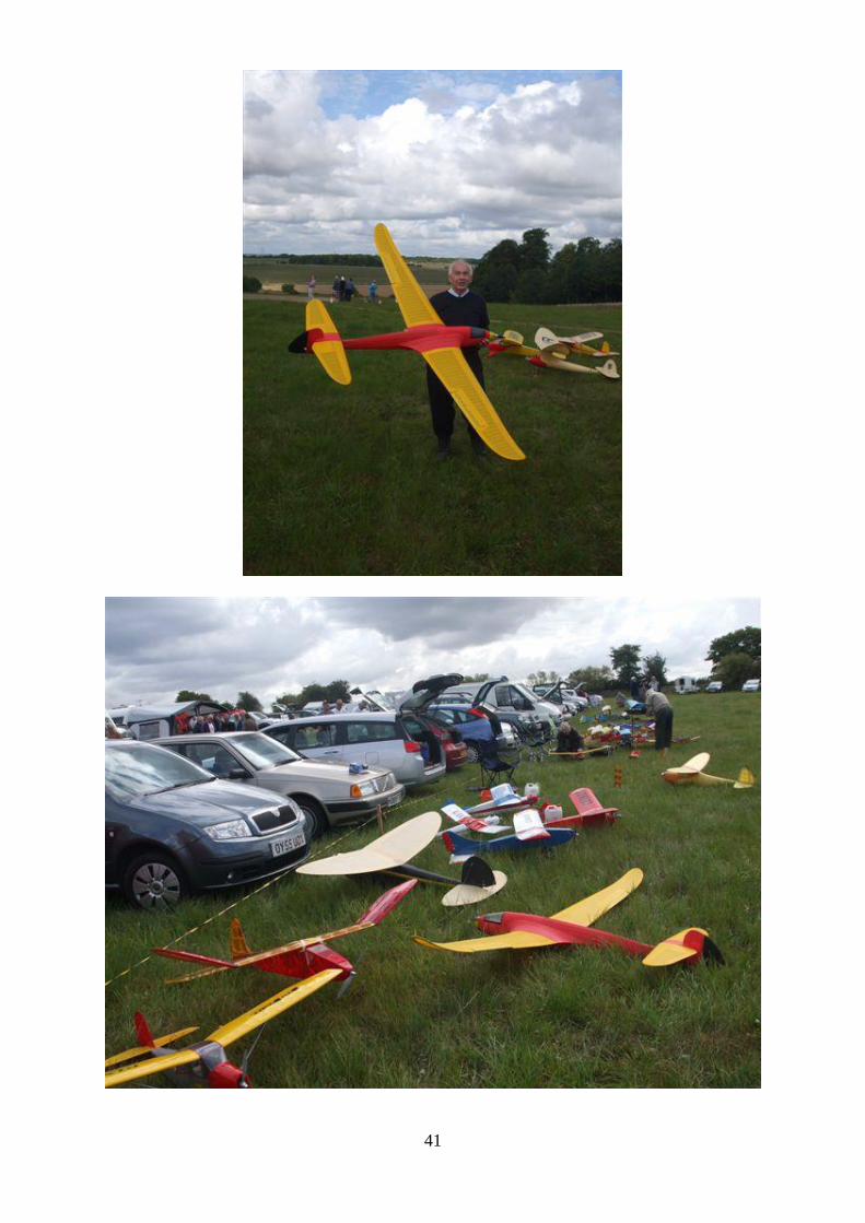
Cocklebarrow Farm Vintage R/C by Tony Tomlin
The R/C Vintage meeting held at Cocklebarrow Farm on Sunday, 14th August was the second of three being
held at this popular Cotswold site in 2011. As before the meeting was smoothly run by Paul and Val
Howkins, for what is now their 21st year, with invaluable help from Mervyn Tilbury and friends. There was
also the 7th round of the hotly contested R/C Tomboy competitions for the 36” and 48” Tomboys, organised
by Tony and Pam Tomlin. The weather was not ideal with, at times, a gusty wind and only occasional
glimpses of the sun. This did little to curb the enthusiasm of the vintage fliers with around 55 signing in
during the day.
There was a varied selection of about 90 models, some old, [some very old!], but also a few new models
not seen before making their debut. There was a Fillons Champion built by John Bowring, built for electric
power, which looked superb with the prop assembly blending in seamlessly with the nose. Mervyn Tilbury
had one of the two 1938, Charles Williams designed, 84” Dragonflys, his powered with a Laser 70 while the
other nearly identical model was flown by Dave Bell. These were both built from a plan supplied by Paul
Howkins. A number of Frog designs were to be seen with the Frog Fireflys of Chris Hughes and Rob Smith
flying regularly. Models ranged from the smallest, a Sharkface and a couple of Wee Snifters, Matadors,
Galahads and Junior Sixtys, Radio Queens and Princesses, Cloud Airmaster, Great News, Scorpion and
many others up to the largest, the Mercury of Garth Pierce. Crashes were few but the large Ranger of Bob
Stanley crashed heavily after a control malfunction!
Tomboy 3
After the poor year we have had weatherwise, the entries in the Tomboy Competitions in 2011 have been a
little down on previous years [the meetings started by David Boddington are now in their 6th year]. So it
was a pleasant surprise to have 16 models booked in for the Mills .75 powered Tomboy 3 event. A number
it appears had been built from the kits produced by Derek Foxwell of the Old School Model Aeroplane
Company. To date he has supplied over 350 of these kits [both 36” and 48”] worldwide and the demand
shows little sign of falling off.
Two flights of 4 minutes or more were required to qualify for the mass launch flyoff. Unfortunately Derek
Collin and Colin Shepherd had trimming problems and were unable to make the flyoff. The majority of the
competitors were regulars although we welcomed Steven Roberts and Chris Bishop to their first event and
Derek Etheridge back for his second attempt at Tomboy 3s. Derek flew at the last Cocklebarrow Farm
meeting in June and lost his model downwind. His day started well as, on arriving at the meeting, he
discovered the model had been returned undamaged that morning by a local farmer who had rescued it from
the jaws of a Combined Harvester !
At 14.00 hrs the 14 competitors lined up for the 90 second start up time plus the normal 15 seconds no
fueling, hold time. The sound of 14 fast revving engines heightened the excitement of what was to come.
Nick Skyrme was the starter and as the start board was lowered the sky was immediately full of Tomboys all
successfully avoiding each other and all pushing into the breeze as they climbed away. Steven Roberts was
soon down having, in the excitement of his first event, not topped his tank up in the allowed 90 secs. Most of
the engines stopped around 2 minutes and Bob Young, George Ford, Derek Etheridge and Brian Brundell
were all in sink and were down in under 5 minutes. James Collis landed at 5 mins 20 secs to be followed by
Paul Netton, Chris Bishop and John Strutt all in the same minute. Of the remaining five, Brian Ball was next
to land, followed by Stephen Powell, with Tom Airey claiming 3rd place at 5 seconds over 7 minutes, the
three landing all within the same 20 seconds. Tony Tomlin had found some slope lift and after being
‘parked’ in the sky for most of the flight slowly descended, landing smoothly a little under half a minute
after Tom. This left Jeff Fellows, who was still at an eye straining height, to glide in, a convincing winner.

40
He was down in 10 mins 39 secs to the applause of the other competitors and the many interested
spectators.
Tomboy 3 results
1. Jeff Fellows 10 min 39 sec, 2. Tony Tomlin 7 min 32 sec, 3 Tom Airey 7 min 05 sec, 4 Stephen
Powell 6 min 57 sec 5.Brian Ball 6 min 45 sec 6 John Strutt 6 min 27 sec 7 Chris Bishop 6 min
13 secs 8. Paul Netton 5 mins 45 sec, 9 James Collis 5 min 20 sec 10 Brian Brundell 4 min 51
sec 11 Derek Etheridge 4 min 04 sec 12 George Ford 4 min 00s 13. Bob Young 3 min 29 secs 14.
Steven Roberts 0 min 38 secs.
Tomboy Senior
After the excitement of the busy Tomboy 3 competition the Tomboy Senior competition had only seven
models making the flyoff with both Chris Shepherd and Stephen Powell failing to qualify. Stephen was very
unfortunate with a transmitter programming problem leading to a crash that left him with a badly damaged
fuselage. The other fliers were the regulars with John Strutt from Billericay, Essex hoping to carry on his
winning streak from the last event, and George Ford flying again for the first time this year.
The wind speed had noticeably increased from the Tomboy 3 event and there were a couple of fliers seen
packing under the trailing edge of their Tomboy wings to improve penetration. The rules and start up were
the same as for the Tomboy 3s. The launch was considerably less frantic with the sound of the slower
revving Mills 1.3s and of course a smaller field. All of the models climbed away, appearing to be flying
much more slowly due to their greater size. George Ford was soon in trouble with a short engine run and
was down in just under 2 mins. Derek Collin was doing well but missed out on the available lift, landing
after a little over 6mins, a reasonable time, whilst the other five models all climbed to a good height,
estimated at around 700ft. Brian Ball had suddenly broken away from the pack with a control problem,
spiralling down and landing just out of the field. The only damage was a broken prop! Tom Airey had
found good lift and was still climbing, Tony Tomlin, Andrew Fellows and John Strutt were descending, all
down within 30 seconds of each other, John claiming 2nd place and Andrew 3rd. Tom Airey then did his
very controlled dive back down, landing smoothly in the centre of the strip at 10 mins 31secs, receiving a
well deserved round of applause.
Tomboy Senior Results
1. Tom Airey 10 mins 31 secs 2.John Strutt 9 mins 34 secs 3. Andrew Fellows 9 mins 20 secs
4 Tony Tomlin 9 mins 01 secs 5. Derek Collin 6 mins 20secs 6. George Ford 1 min 59 secs 7.
Brian Ball Landed out
The awards and certificates were presented by Val Howkins. Thanks again Paul and Val for a very nice day
41

42

43
Derek Foxwell of Old School Modelaeroplane Factory talking to Barry Collis

44
Mervyn Tilbury looking pleased
Cloudtramp 2011at Epsom Downs Tony Tomlin
Saturday, August 6th was the date for the Cloud Tramp mass launch on Epsom Downs. The Cloud Tramp
plan was first published in the Model Aeroplane News in 1954. This simple all sheet, rubber powered model
was designed by the American, Charles Grant to encourage the youth of the day to become aeromodellers.
Over the years this has become an international event with a mass launch of these models each year at
exactly the same time and date worldwide. So when the models are launched at 5pm BST at Epsom Downs,
in America, for example it will be 8am and 6am in Australia [The models are launched under flood lights in
the dark].
This year at Epsom Downs 32 fliers lined up for the launch. It was a dull day but luckily without the rain
that often seems to dog the event. As always there was the normal good natured banter between fliers as the
clock ticked towards launch time. Ted Horne was the starter and after the group photos were taken, motors
were wound and a ragged line of fliers formed. Spot on time Ted sounded the starting whistle and all the
models soared away, with some appreciative comment [even some clapping] by a few members of the
public who had wandered over to see who these bunch of eccentrics were! Some models flew for only a few
seconds but others climbed well and were soon drifting downwind followed by the “fetchermites” [or to be
more correct “fetchergrandfathers”!]. The photographs tell it all.
Middle Wallop Sunday 28 August 2011
You don’t need a calendar or other traditional devices to know when it is time to go flying at Middle Wallop
the fool proof way is to look out the window and if all trees are bending over at 45 degrees or more you
know an event is on. For FF a plastic bag ripped from a dustbin and reaching 5,000 ft is also a sign to get
out the Wakefield. Better still if there is a light drizzle as well. Sunday reached the expected criteria. This
was a three day event with FF all three days and R/C and CL on the Sunday.
There were about 25 signed on for R/C and a handful flying CL. Trouble is this event always clashes with
The Nationals thus numbers on the CL side are reduced. Still I suspect TT will do a report but in meantime
here’s a few photos.

45
Garth Pearce and Mercury IV David Ashenden with his Utility
Colin Smith, he supplies Phil’s plans
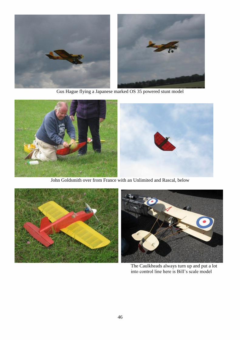
46
Gus Hague flying a Japanese marked OS 35 powered stunt model
John Goldsmith over from France with an Unlimited and Rascal, below
The Caulkheads always turn up and put a lot
into control line here is Bill’s scale model
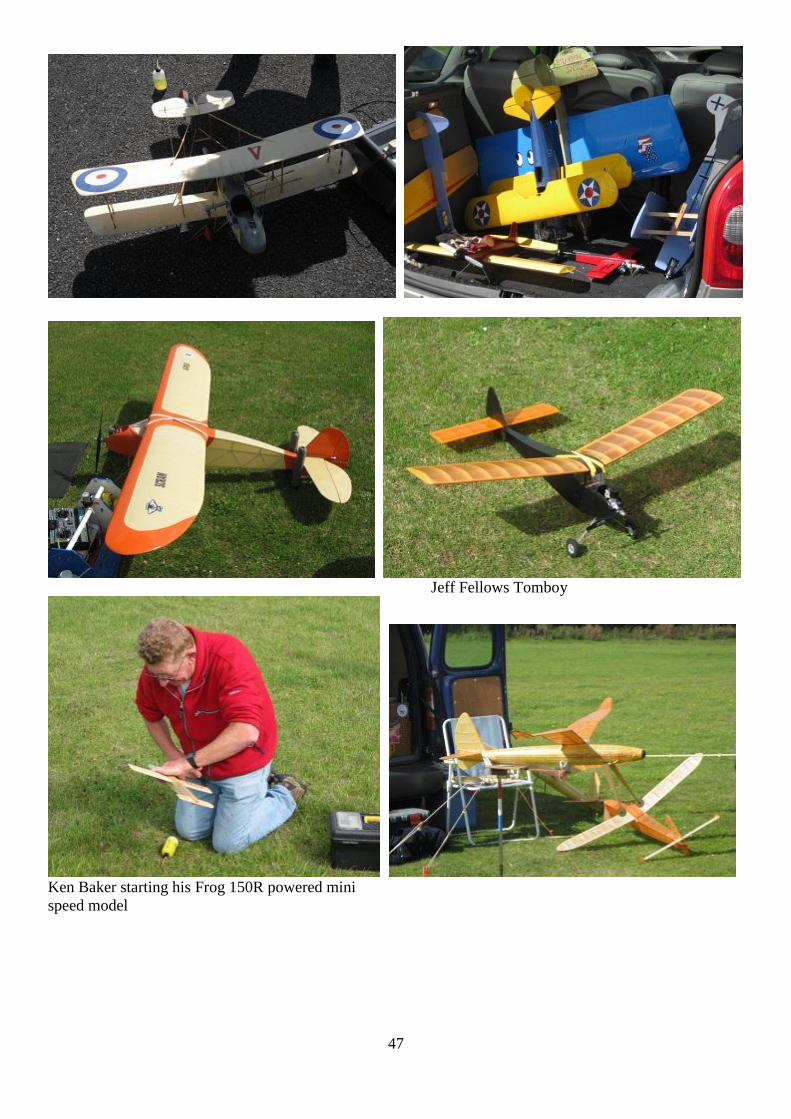
47
Jeff Fellows Tomboy
Ken Baker starting his Frog 150R powered mini
speed model
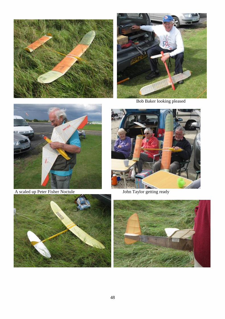
48
Bob Baker looking pleased
A scaled up Peter Fisher Noctule John Taylor getting ready
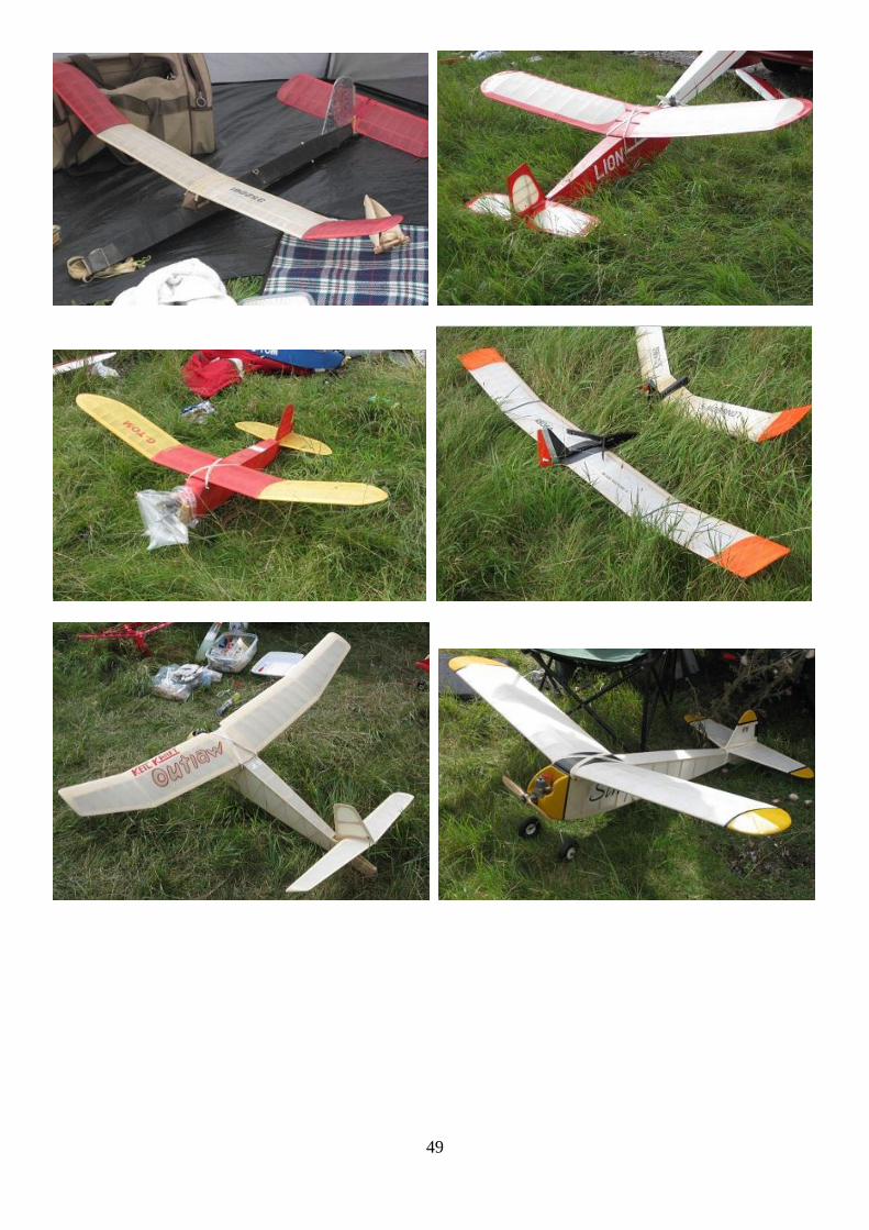
49
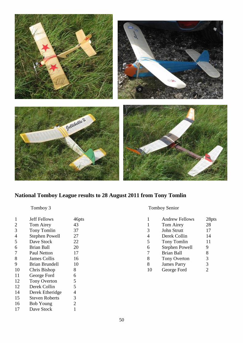
50
National Tomboy League results to 28 August 2011 from Tony Tomlin
Tomboy 3 Tomboy Senior
1 Jeff Fellows 46pts 1 Andrew Fellows 28pts
2 Tom Airey 43 1 Tom Airey 28
3 Tony Tomlin 37 3 John Strutt 17
4 Stephen Powell 27 4 Derek Collin 14
5 Dave Stock 22 5 Tony Tomlin 11
6 Brian Ball 20 6 Stephen Powell 9
7 Paul Netton 17 7 Brian Ball 8
8 James Collis 16 8 Tony Overton 3
9 Brian Brundell 10 8 James Parry 3
10 Chris Bishop 8 10 George Ford 2
11 George Ford 6
12 Tony Overton 5
12 Derek Collin 5
14 Derek Etheridge 4
15 Steven Roberts 3
16 Bob Young 2
17 Dave Stock 1
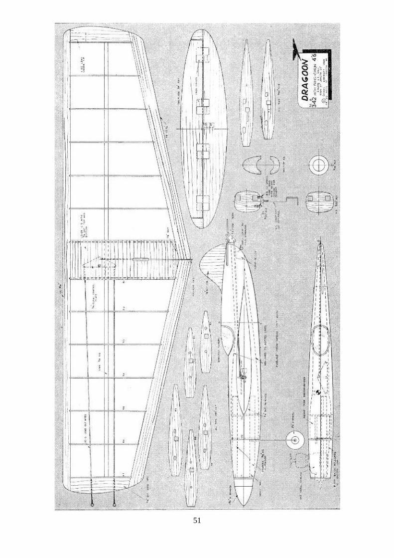
51

52
Dragoon a sleak stunt / combat model for 2.5 – 3.5 cc motors by Hoh Fang-Chiun.
From Model Aurcraft February 1961
When “Combat” was first introduced the models flown were usually old stunters retrieved from the scrap
box. However, in a very short time, this new branch of the sport rapidly gained in popularity, and specialist
combat models were produced with a stunt performance but simplified construction. As the mortality rate of
models increased, the emphasis was more and more on ease of building until, today, a combat model is the
simplest and often the ugliest of contest models! In an attempt to get away from this rut, I have designed
Dragoon, in which I have tried to combine a slick, manoeuvrable stunt model, with a fast, easy-to-build
combat job. Powered by a well-broken-in Taifun “Tornado” 2.5 c.c. diesel, the prototype flies at an average
speed of 6o m.p.h., and with a line length of 55 ft. it is capable of doing the most advanced manoeuvres.
Construction
Build the entire mainplane first, by first joining up the 9/16 in. sq. leading edge and 3/8 in. sq. hard balsa
main- spar. Cut all the ribs from 1/16 in. medium balsa,
not forgetting to cut slots in the port wing ribs for the lead-
out wires. Slide and cement the ribs onto the mainspar and
check that they line up correctly. Note that the 3 mm
plywood bellcrank mount has to be cemented in place
before the ribs are added. Cut notches for the ribs in the
leading and trailing edges and cement these in place. Add
the 1/8 in. sheet balsa tips and insert the 14 s.w.g. tubes
through the port tip for the lead-outs. Don’t forget to fix a
1oz. lead weight in the
starboard wing tip. Before sheet covering the centre part of the mainplane, cement the 1/8 in. balsa
reinforcement at the trailing edge joint and bolt the complete bellcrank assembly in place.
The entire fuselage is hollowed from balsa block except for the engine compartment which is built first. Cut
the three plywood formers (F1-F3) and the hardwood engine mounts. If you wish to install a drop-off
undercarriage, cement and bind the two 14 s.w.g. brass tubes to the firewall at this stage. Now install the fuel
tank between formers F2 and F3 and cement these to the bearers.
When dry, cut away (if necessary) the wood on the inside of the bearers to suit your engine. To mount the
engine, use nuts and bolts—never use wood screws for this purpose. While the engine is bolted in place, fix
the ring former F1 in position by means of two small nails.
In order to obtain a strong and straight joint between the nose assembly and the mainplane, the two 1/4 in.
balsa webs must be cemented in position. Join the nose assembly to the mainplane with plenty of cement.
For the main fuselage, select two medium-soft balsa blocks and cut these roughly to the required size.
Commence to shape the blocks by sawing out the mainplane slot, then pin the blocks together and trace the
fuselage top view directly on the block and saw it to shape. The fuselage side view is transferred in the same
way, always keeping the two blocks pinned firmly together. Before separating the blocks, sand them to
the correct section. Now separate the blocks and hollow them out to the dotted lines shown on the plan.
Cement the blocks to the mainplane, add the nose block and balsa fillet at the tail, and give the whole
fuselage a final sanding.
The tailplane and the fin, which are from 1/8 in. hard balsa, can now be cemented in place, but check that
there is enough elevator movement (about 30 deg. up and down is sufficient). Note that the fin has a
lifting section and is slightly offset. Complete the model by fitting the canopy—a commercial one can be
used—and install a small pilot for added realism.
Before covering the model give all outside balsa surfaces two coats of thin clear dope. Cover the main-
plane with either silk or heavyweight tissue, but be sure that the grain of the covering material runs spanwise
to minimise “ sag,” between the ribs. Cover the rest of the model with lightweight tissue. Apply four coats
of clear dope, sanding lightly between each coat. The model is now ready for colouring, but don’t forget to
protect the transparent canopy with Sellotape during the process. The engine cowling can be made of
thin sheet metal (aluminium or brass) or moulded in sheet acetate. It is held in place with four small wood
screws. Bend the drop-off under carriage if required, and check that it drops freely.
Before you go out to fly, check that the model balances correctly, and that there is no warp in the main-
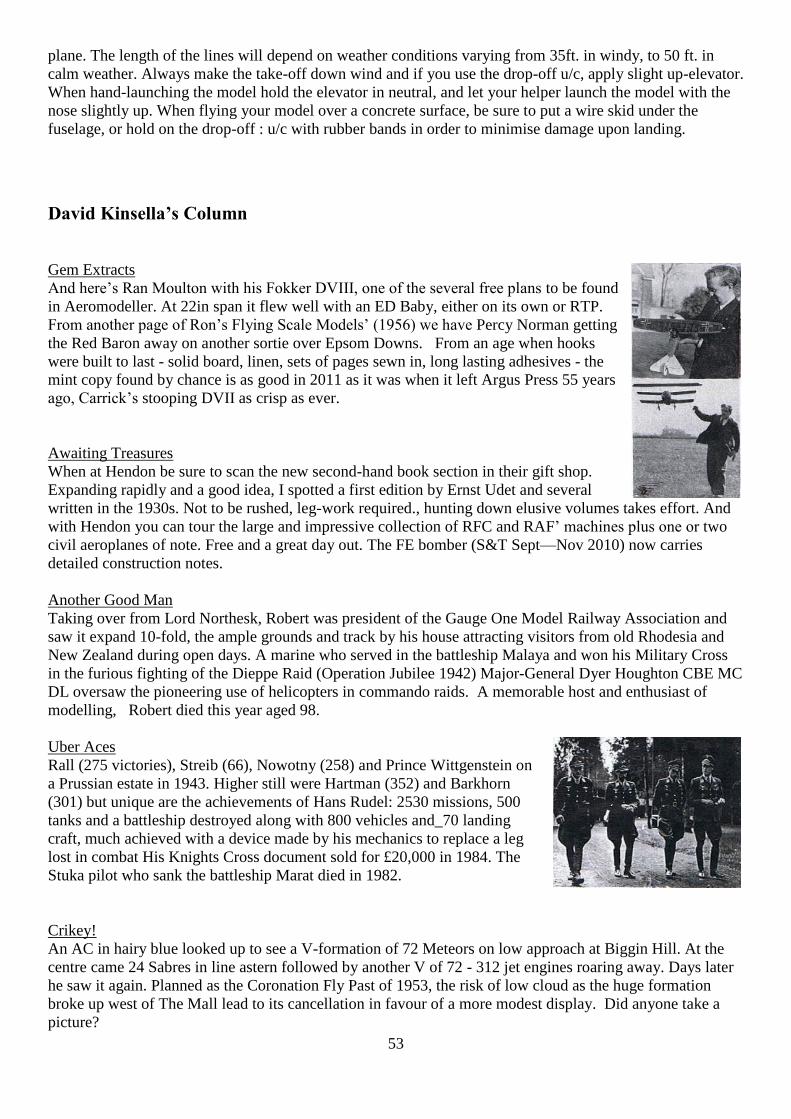
53
plane. The length of the lines will depend on weather conditions varying from 35ft. in windy, to 50 ft. in
calm weather. Always make the take-off down wind and if you use the drop-off u/c, apply slight up-elevator.
When hand-launching the model hold the elevator in neutral, and let your helper launch the model with the
nose slightly up. When flying your model over a concrete surface, be sure to put a wire skid under the
fuselage, or hold on the drop-off : u/c with rubber bands in order to minimise damage upon landing.
David Kinsella’s Column
Gem Extracts
And here’s Ran Moulton with his Fokker DVIII, one of the several free plans to be found
in Aeromodeller. At 22in span it flew well with an ED Baby, either on its own or RTP.
From another page of Ron’s Flying Scale Models’ (1956) we have Percy Norman getting
the Red Baron away on another sortie over Epsom Downs. From an age when hooks
were built to last - solid board, linen, sets of pages sewn in, long lasting adhesives - the
mint copy found by chance is as good in 2011 as it was when it left Argus Press 55 years
ago, Carrick’s stooping DVII as crisp as ever.
Awaiting Treasures
When at Hendon be sure to scan the new second-hand book section in their gift shop.
Expanding rapidly and a good idea, I spotted a first edition by Ernst Udet and several
written in the 1930s. Not to be rushed, leg-work required., hunting down elusive volumes takes effort. And
with Hendon you can tour the large and impressive collection of RFC and RAF’ machines plus one or two
civil aeroplanes of note. Free and a great day out. The FE bomber (S&T Sept—Nov 2010) now carries
detailed construction notes.
Another Good Man
Taking over from Lord Northesk, Robert was president of the Gauge One Model Railway Association and
saw it expand 10-fold, the ample grounds and track by his house attracting visitors from old Rhodesia and
New Zealand during open days. A marine who served in the battleship Malaya and won his Military Cross
in the furious fighting of the Dieppe Raid (Operation Jubilee 1942) Major-General Dyer Houghton CBE MC
DL oversaw the pioneering use of helicopters in commando raids. A memorable host and enthusiast of
modelling, Robert died this year aged 98.
Uber Aces
Rall (275 victories), Streib (66), Nowotny (258) and Prince Wittgenstein on
a Prussian estate in 1943. Higher still were Hartman (352) and Barkhorn
(301) but unique are the achievements of Hans Rudel: 2530 missions, 500
tanks and a battleship destroyed along with 800 vehicles and_70 landing
craft, much achieved with a device made by his mechanics to replace a leg
lost in combat His Knights Cross document sold for £20,000 in 1984. The
Stuka pilot who sank the battleship Marat died in 1982.
Crikey!
An AC in hairy blue looked up to see a V-formation of 72 Meteors on low approach at Biggin Hill. At the
centre came 24 Sabres in line astern followed by another V of 72 - 312 jet engines roaring away. Days later
he saw it again. Planned as the Coronation Fly Past of 1953, the risk of low cloud as the huge formation
broke up west of The Mall lead to its cancellation in favour of a more modest display. Did anyone take a
picture?

54
Chance Meeting
Bumped into Andrew Roberts in the sunshine by the Garrick, he on a quick visit from the US. A leading
historian of the modern period, his acclaimed life of Salisbury and other works place the young Englishman
squarely in the front rank. A treat to hear him on Any Questions when he is over here.
Great Idea
By his deeds, designs and words Ron Moulton was the great enthusiast of control line flying. He wrote the
standard work on it and even in Scale Flying Models (1956) he devotes eleven pages to it. Now David
Finch’s idea for a non Oliver VTR series for a cup or shield in the name of RGM is spot on, a great idea and
really a must in celebrating the many achievements of our departed chief. Well done, David! Hopefully
much traction will be gained by 2012 and I’d be honoured to make a contribution to the cup or shield fund.
Brighton Winner
And the above leads us nicely into Phil Smith, Ted Martin and the Veron
Midget Mustang (Ameo 3.5) that won the UK’s first Team Race in 1950
(another Phil Smith design doing it again at VTR2000). Phil’s life
covered recently in Sticks & Tissue (June to December 2009), Ted
Martin was a huge enthusiast of live steam model railways, a layout of
cuttings, tunnels, stations and engine sheds covering his three acre
garden. Ted designed model aero engines, worked for GM in Canada
then joined MG to work on the Twin Cam project, raced at Brands,
designed for Ford, sold other designs to French manufacturers and then
retired - at 43.
Blofield’s Base
Command centres in volcanos and war rooms of Reagan approval were the work
of Ken Adam. Fleeing Germany in. 1934 he flew in the RAF, aware that he
would be seen as a traitor if he survived a crash in that country. After UCL Ken
entered the movie industry as a draughtsman, later creating ideas for sets rather
than sticking to facts. Dr Strangelove’s antics in the impressive war room made
the movie (1963), President Reagan surprised that the America’s reality was not
up to Adam’s invention. Here Lewis Gilbert (Bader movie) is on the Bond subs-
and-tanker-set designed by the pilot who flew Typhoons over Falaise Gap.
Largest set in Europe, it was opened by PM Harold Wilson.
Twanky Man?
One of Ian Fleming’s jobs as a Wavy Navy (RNVR) officer working in the Admiralty was to think up
schemes. The enemy codes vital to reduce shipping losses, Operation Ruthless provided for a captured
German bomber to ditch in the sea. The English crew fluent in German would then radio for help. Taken
aboard a rescue boat or submarine, our boys would take over and return with the vital code books. Papers
exist, one or two signed F. Was it F for Fleming or F for Frank Birch? Birch was involved and in his spare
time wrote panto scripts for Widdow Twanky.
0-Level Info
Over from Portugal for Ron’s Day, I had a chat with Julio by the VTR circles. Touching on the Lines of
Torres Veras (by Wellington near Lisbon) I heard a nearby modeller say to another: “You certainly get a
good education, here”.

55
Brave Pierre
Busy with my Skyleada Typhoon an age ago Peter Shearman told me to
read The Big Show. Selling 3 million, copies and first published in. 1951,
Tempest ace Pierre Closterman DSO DFC OdG aboard Le Grand Charles
pictured here tells us of tangles with FWI9Os and jet 262s, hitting ammo
trains and nil feet blasts along the Dortmund canal. Trained in Los Angeles
and on the RAF’s most powerful fighter, Closterman hit VI sites, ships and
factories and swept the skies above Normandy. Always a big-game
fisherman, the dashing Frenchman retired to the Pyrenees. An add-on
comes from a letter written by a RAF officer in which he tells me of
Closterman’s arrival at a dance. An Errol Flynn type and famous, he swept
a girl off her feet and headed for London. Years later the officer married
the girl.
Doing The Continental
With its famous swoopy rear and cast aluminiun frames, the Bentley R-
Type Continental was the one to waft across France to the Med. A big
strider when 100mph was still the grail, the sleek R-Type was an
essential for those with large yachts and private, aeroplanes and a castle
or two. Grand Prix Legends will sell 1:18 models in their new shop near
Leicester Square (Cecil Court) and front Guildford HQ (0844 887 8888).
GFL stocks the best of the best)
Oliver’s Scribe
John Goodall and son Paul are great enthusiasts. John gave us the first and only book on Oliver engines,
many fine editions of his Model Engine World and maintained an impressive stock of motors for those in
need, prompt and top notch service his famous brand. These days Paul is at the helm, John on the blower
telling me about his fun fettling and firing up Classic bikes for hill and
track, even part way through an ohc conversion, of his own design
(drawn up when we had all that snow!). Model aeroplanes not
neglected, here’s John with a Mk 2 Ranger ex Campbell and a 10cc
Nordec Speed job. Early Nordecs were not too powerful but this one
really goes, only smallish wings damping mph due to angle of attack.
Nordec’s (North Downs Engineering Co) of Godstone Road,
Whyteleaf, Surrey was really a large garage also making big
Roots-type blowers, ifs systems for Fords and even Bugattis, and at
least one Nordec sports car. Thanks in part to Nordec superchargers the Candidi Provocatores team of JI
Allards mashed the Trials opposition in the late 1940s and set hill climb records in Europe. Give Paul a ring
(01283 713715) and that McCoy 60 or Eta 29 will be on its way. Forget that new carpet, this hardware is
essential!
Good Kit
Seen at Old Warden, P S Aeroproducts stock good stuff for control line operators in need of the best: props,
tanks, lines, dope, cranks, horns and loads more. Based in Middlesex, Paul Winter (0208 958 6731) awaits
to lend a helping hand.
The Flyer
My letter in Classic Boat didn’t do it, but possibly the reach of S&T can conjure information on the Flyer.
For years a sight off Southend pier was the white roostertail of Flyer, a varnished Speed boat that did her
stuff from time to time between Thorpe By and Benfleet. Of the old style, her name in red-edged white
letters either side, even at a distance the noise was like a MerlinVI2 in take-off mode. Where is she now?
That’s the question I’d like answered. And tn. there was the grey MTB off Westcliff….
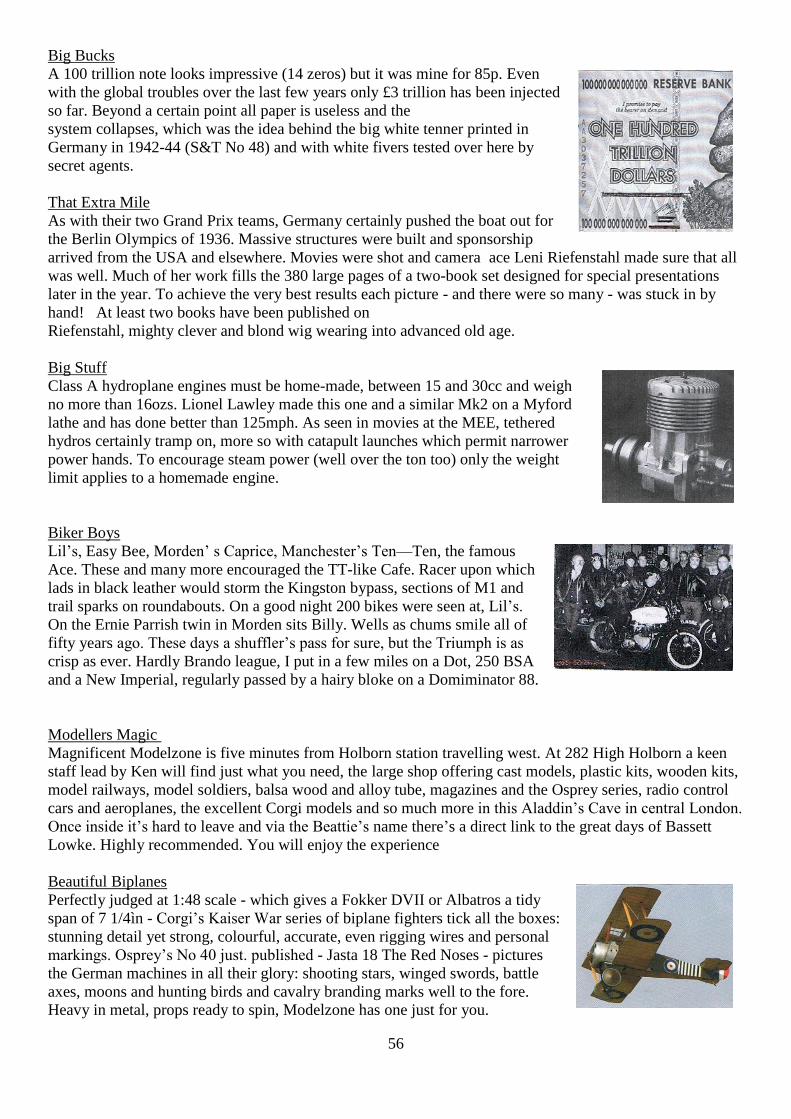
56
Big Bucks
A 100 trillion note looks impressive (14 zeros) but it was mine for 85p. Even
with the global troubles over the last few years only £3 trillion has been injected
so far. Beyond a certain point all paper is useless and the
system collapses, which was the idea behind the big white tenner printed in
Germany in 1942-44 (S&T No 48) and with white fivers tested over here by
secret agents.
That Extra Mile
As with their two Grand Prix teams, Germany certainly pushed the boat out for
the Berlin Olympics of 1936. Massive structures were built and sponsorship
arrived from the USA and elsewhere. Movies were shot and camera ace Leni Riefenstahl made sure that all
was well. Much of her work fills the 380 large pages of a two-book set designed for special presentations
later in the year. To achieve the very best results each picture - and there were so many - was stuck in by
hand! At least two books have been published on
Riefenstahl, mighty clever and blond wig wearing into advanced old age.
Big Stuff
Class A hydroplane engines must be home-made, between 15 and 30cc and weigh
no more than 16ozs. Lionel Lawley made this one and a similar Mk2 on a Myford
lathe and has done better than 125mph. As seen in movies at the MEE, tethered
hydros certainly tramp on, more so with catapult launches which permit narrower
power hands. To encourage steam power (well over the ton too) only the weight
limit applies to a homemade engine.
Biker Boys
Lil’s, Easy Bee, Morden’ s Caprice, Manchester’s Ten—Ten, the famous
Ace. These and many more encouraged the TT-like Cafe. Racer upon which
lads in black leather would storm the Kingston bypass, sections of M1 and
trail sparks on roundabouts. On a good night 200 bikes were seen at, Lil’s.
On the Ernie Parrish twin in Morden sits Billy. Wells as chums smile all of
fifty years ago. These days a shuffler’s pass for sure, but the Triumph is as
crisp as ever. Hardly Brando league, I put in a few miles on a Dot, 250 BSA
and a New Imperial, regularly passed by a hairy bloke on a Domiminator 88.
Modellers Magic
Magnificent Modelzone is five minutes from Holborn station travelling west. At 282 High Holborn a keen
staff lead by Ken will find just what you need, the large shop offering cast models, plastic kits, wooden kits,
model railways, model soldiers, balsa wood and alloy tube, magazines and the Osprey series, radio control
cars and aeroplanes, the excellent Corgi models and so much more in this Aladdin’s Cave in central London.
Once inside it’s hard to leave and via the Beattie’s name there’s a direct link to the great days of Bassett
Lowke. Highly recommended. You will enjoy the experience
Beautiful Biplanes
Perfectly judged at 1:48 scale - which gives a Fokker DVII or Albatros a tidy
span of 7 1/4ìn - Corgi’s Kaiser War series of biplane fighters tick all the boxes:
stunning detail yet strong, colourful, accurate, even rigging wires and personal
markings. Osprey’s No 40 just. published - Jasta 18 The Red Noses - pictures
the German machines in all their glory: shooting stars, winged swords, battle
axes, moons and hunting birds and cavalry branding marks well to the fore.
Heavy in metal, props ready to spin, Modelzone has one just for you.
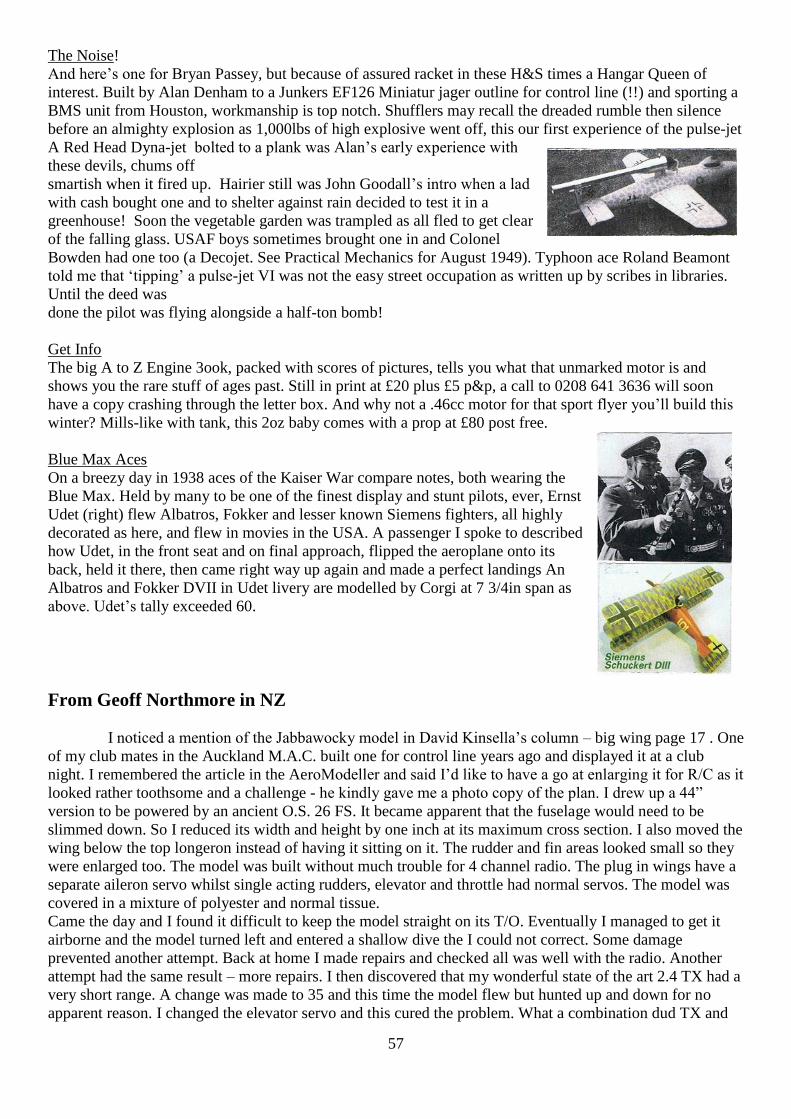
57
The Noise!
And here’s one for Bryan Passey, but because of assured racket in these H&S times a Hangar Queen of
interest. Built by Alan Denham to a Junkers EF126 Miniatur jager outline for control line (!!) and sporting a
BMS unit from Houston, workmanship is top notch. Shufflers may recall the dreaded rumble then silence
before an almighty explosion as 1,000lbs of high explosive went off, this our first experience of the pulse-jet
A Red Head Dyna-jet bolted to a plank was Alan’s early experience with
these devils, chums off
smartish when it fired up. Hairier still was John Goodall’s intro when a lad
with cash bought one and to shelter against rain decided to test it in a
greenhouse! Soon the vegetable garden was trampled as all fled to get clear
of the falling glass. USAF boys sometimes brought one in and Colonel
Bowden had one too (a Decojet. See Practical Mechanics for August 1949). Typhoon ace Roland Beamont
told me that ‘tipping’ a pulse-jet VI was not the easy street occupation as written up by scribes in libraries.
Until the deed was
done the pilot was flying alongside a half-ton bomb!
Get Info
The big A to Z Engine 3ook, packed with scores of pictures, tells you what that unmarked motor is and
shows you the rare stuff of ages past. Still in print at £20 plus £5 p&p, a call to 0208 641 3636 will soon
have a copy crashing through the letter box. And why not a .46cc motor for that sport flyer you’ll build this
winter? Mills-like with tank, this 2oz baby comes with a prop at £80 post free.
Blue Max Aces
On a breezy day in 1938 aces of the Kaiser War compare notes, both wearing the
Blue Max. Held by many to be one of the finest display and stunt pilots, ever, Ernst
Udet (right) flew Albatros, Fokker and lesser known Siemens fighters, all highly
decorated as here, and flew in movies in the USA. A passenger I spoke to described
how Udet, in the front seat and on final approach, flipped the aeroplane onto its
back, held it there, then came right way up again and made a perfect landings An
Albatros and Fokker DVII in Udet livery are modelled by Corgi at 7 3/4in span as
above. Udet’s tally exceeded 60.
From Geoff Northmore in NZ
I noticed a mention of the Jabbawocky model in David Kinsella’s column – big wing page 17 . One
of my club mates in the Auckland M.A.C. built one for control line years ago and displayed it at a club
night. I remembered the article in the AeroModeller and said I’d like to have a go at enlarging it for R/C as it
looked rather toothsome and a challenge - he kindly gave me a photo copy of the plan. I drew up a 44”
version to be powered by an ancient O.S. 26 FS. It became apparent that the fuselage would need to be
slimmed down. So I reduced its width and height by one inch at its maximum cross section. I also moved the
wing below the top longeron instead of having it sitting on it. The rudder and fin areas looked small so they
were enlarged too. The model was built without much trouble for 4 channel radio. The plug in wings have a
separate aileron servo whilst single acting rudders, elevator and throttle had normal servos. The model was
covered in a mixture of polyester and normal tissue.
Came the day and I found it difficult to keep the model straight on its T/O. Eventually I managed to get it
airborne and the model turned left and entered a shallow dive the I could not correct. Some damage
prevented another attempt. Back at home I made repairs and checked all was well with the radio. Another
attempt had the same result – more repairs. I then discovered that my wonderful state of the art 2.4 TX had a
very short range. A change was made to 35 and this time the model flew but hunted up and down for no
apparent reason. I changed the elevator servo and this cured the problem. What a combination dud TX and

58
servo! Further flying showed a serious lack of power so a change was made to electric and this has made a
better performing model. Not a lot of flying has been possible, due to our winter weather, so much more
remains to be found out about general handling. Anyway it has been a bit of fun which is the important
thing. Geoff Northmore.
P.S. The odd green thing on the wall is my version of the Cekoadon – not very successful as yet.
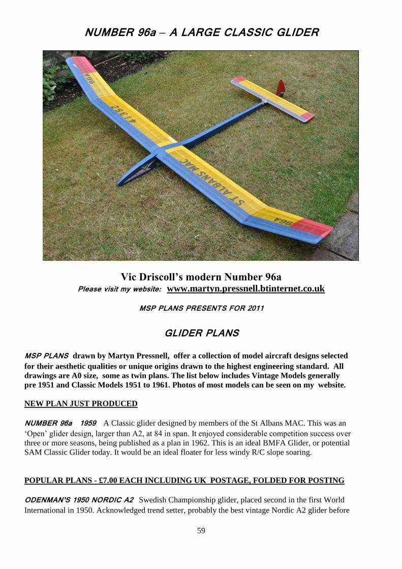
59
NUMBER 96a – A LARGE CLASSIC GLIDER
Vic Driscoll’s modern Number 96a Please visit my website: www.martyn.pressnell.btinternet.co.uk
MSP PLANS PRESENTS FOR 2011
GLIDER PLANS MSP PLANS drawn by Martyn Pressnell, offer a collection of model aircraft designs selected
for their aesthetic qualities or unique origins drawn to the highest engineering standard. All
drawings are A0 size, some as twin plans. The list below includes Vintage Models generally
pre 1951 and Classic Models 1951 to 1961. Photos of most models can be seen on my website.
NEW PLAN JUST PRODUCED
NUMBER 96a 1959 A Classic glider designed by members of the St Albans MAC. This was an
‘Open’ glider design, larger than A2, at 84 in span. It enjoyed considerable competition success over
three or more seasons, being published as a plan in 1962. This is an ideal BMFA Glider, or potential
SAM Classic Glider today. It would be an ideal floater for less windy R/C slope soaring.
POPULAR PLANS - £7.00 EACH INCLUDING UK POSTAGE, FOLDED FOR POSTING
ODENMAN’S 1950 NORDIC A2 Swedish Championship glider, placed second in the first World
International in 1950. Acknowledged trend setter, probably the best vintage Nordic A2 glider before
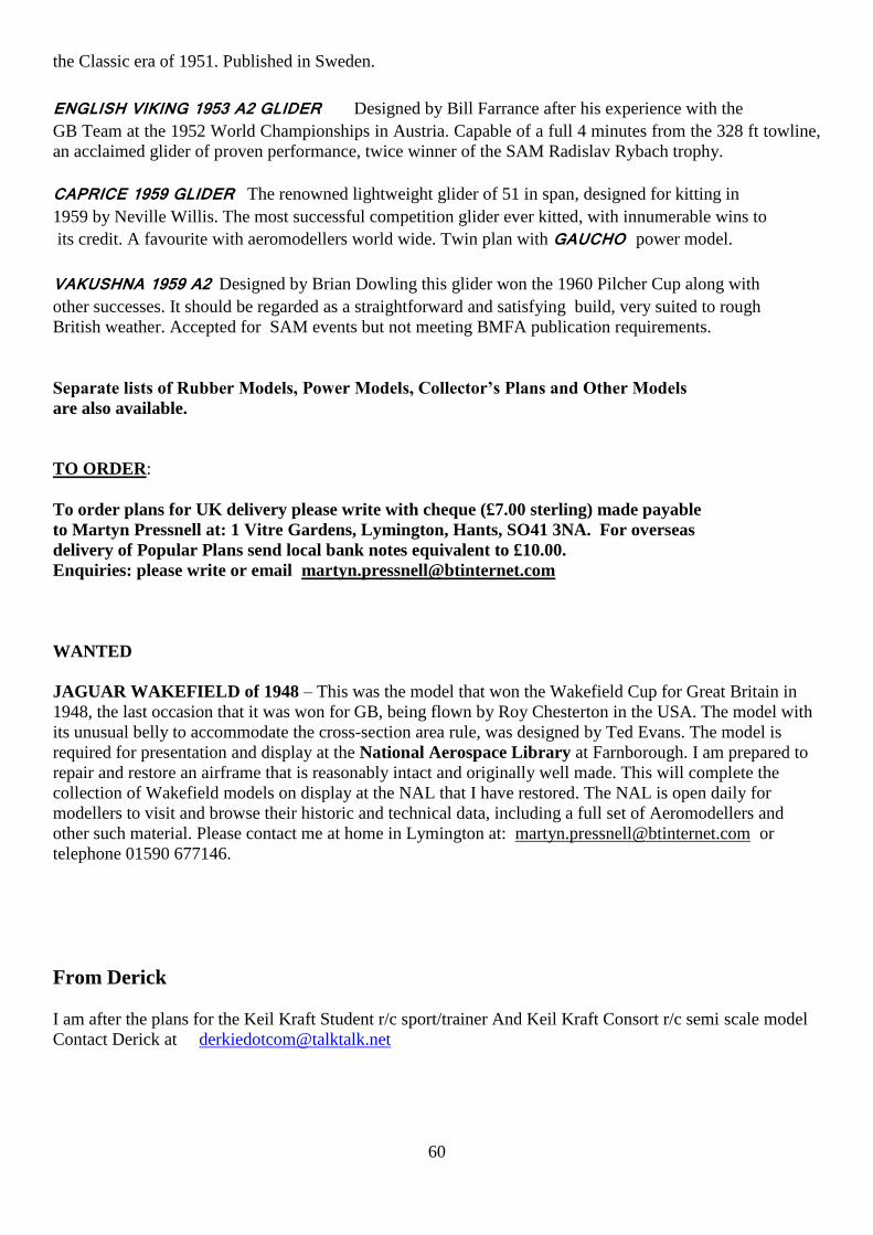
60
the Classic era of 1951. Published in Sweden.
ENGLISH VIKING 1953 A2 GLIDER Designed by Bill Farrance after his experience with the
GB Team at the 1952 World Championships in Austria. Capable of a full 4 minutes from the 328 ft towline,
an acclaimed glider of proven performance, twice winner of the SAM Radislav Rybach trophy.
CAPRICE 1959 GLIDER The renowned lightweight glider of 51 in span, designed for kitting in
1959 by Neville Willis. The most successful competition glider ever kitted, with innumerable wins to
its credit. A favourite with aeromodellers world wide. Twin plan with GAUCHO power model.
VAKUSHNA 1959 A2 Designed by Brian Dowling this glider won the 1960 Pilcher Cup along with
other successes. It should be regarded as a straightforward and satisfying build, very suited to rough
British weather. Accepted for SAM events but not meeting BMFA publication requirements.
Separate lists of Rubber Models, Power Models, Collector’s Plans and Other Models
are also available.
TO ORDER:
To order plans for UK delivery please write with cheque (£7.00 sterling) made payable
to Martyn Pressnell at: 1 Vitre Gardens, Lymington, Hants, SO41 3NA. For overseas
delivery of Popular Plans send local bank notes equivalent to £10.00.
Enquiries: please write or email [email protected]
WANTED
JAGUAR WAKEFIELD of 1948 – This was the model that won the Wakefield Cup for Great Britain in
1948, the last occasion that it was won for GB, being flown by Roy Chesterton in the USA. The model with
its unusual belly to accommodate the cross-section area rule, was designed by Ted Evans. The model is
required for presentation and display at the National Aerospace Library at Farnborough. I am prepared to
repair and restore an airframe that is reasonably intact and originally well made. This will complete the
collection of Wakefield models on display at the NAL that I have restored. The NAL is open daily for
modellers to visit and browse their historic and technical data, including a full set of Aeromodellers and
other such material. Please contact me at home in Lymington at: [email protected] or
telephone 01590 677146.
From Derick
I am after the plans for the Keil Kraft Student r/c sport/trainer And Keil Kraft Consort r/c semi scale model
Contact Derick at [email protected]

61
From Belair
Hope you don't mind, but could you mention our latest Vintage List is now out. If readers would like a free
copy, please have them email or call with their details. The list is an A4 brochure and cannot be emailed
without reducing the size/quality, however it is available as a download on our site at
http://www.belairkits.com/Pages.asp?id=14
Regards,
Leon Cole
Belair Kits
Tel: +44 (0)1362 668658
www.belairkits.com
For sale ex Ray Page’s aeromodelling items
Both Fleet TX are still available, the other items are:
Indian mills 75
OK cub 049
Ohlson 60 (no tank broken lug good compression)
Delong 30 (no points or tank)
OS pet
ME merlin (in super merlin box)
OS max 10 NIB
Irvine 36 NIB
ask people to phone/email me 01306 881000
Radio Assisted Free Flight From Andy Brough Vice Chairman SAM 35
Radio Assisted Free Flight is a form of flying which is very suitable for those still interested in free flight,
but who have limited mobility or indeed wish to take up free flight but are not physically able to retrieve.
The arrival of both 2.4GHz radio and micro equipment at very reasonable prices has provided the
possibilities to add radio to any type of model and for it to be flown without the need for traditional flight
line control. Vintage enthusiasts were quick to see the opportunity to fit the equipment to free flight models

62
to allow them to be flown on smaller sites and to avoid the long walk to retrieve. The vintage community
tend to be at the older end of the general
modelling population so this feature is very attractive.
Indeed I’m sure many club sites have a number of such models on their patch flying in circuits along with
the ‘proper’ radio models. However, as vintage modellers like to gather at free flight meetings issues then
arise as to what can and can’t be done. Clearly, just turning up and flying a radio model in the midst of a
group of free flight modellers is not acceptable!
Therefore Sam 35 and the BMFA have come up with a set of guidelines applicable for this type of model
flying. The normal guidelines for radio flying are not applicable for two main reasons; you must not fly
circuits in front of the flight line and the fact that models drift downwind means modellers will cross the
flight line. The guidelines address these issues along with the amount of control allowed and organisation.
Radio Assisted Free Flight Guidelines
1. Models must be free flight models in original design and concept with radio fitted solely to assist in
trimming and recovery. Models must be operated in a ‘free flight’ manner with a clear climb to height
followed by a glide phase.
2. Radio assist is limited to rudder plus one other function (which must be either elevator or throttle).
Additional channels may be used, but only as a motor cut off and/or to activate a dethermaliser.
3. Only legal 2.4GHz radio equipment to be used.
4. Only fly on sites that are clear with adequate open space in compliance with any local rules or conditions
and with due consideration for other people and property.
5. When radio assisted free flight is taking place on a multi use site, it is important that one person is
nominated to co-ordinate the activity and liaise with other site users.
Note: where a group of flyers wish to fly assisted free flight one would expect their flight line to be adjacent
to the free flight line, a precedent set by the FAIR rocket flyers who also fly assisted rocket launched gliders.
Andy Brough
Vice Chairman SAM 35
Issue 1 25/07/2011