Steven T. Myers (NRAO-Socorro)smyers/Synth2010/MyersPolarization10.pdf · 2012-03-13 · •...
68
Polarization in Interferometry Steven T. Myers (NRAO Socorro) (NRAO-Socorro) Twelfth Synthesis Imaging Workshop Socorro, June 8-15, 2010
Transcript of Steven T. Myers (NRAO-Socorro)smyers/Synth2010/MyersPolarization10.pdf · 2012-03-13 · •...
Polarization in InterferometrySteven T. Myers (NRAO Socorro)(NRAO-Socorro)
Twelfth Synthesis Imaging WorkshopSocorro, June 8-15, 2010, ,
Polarization in interferometry• Astrophysics of Polarization• Physics of Polarization• Antenna Response to Polarization• Interferometer Response to Polarization
P l i ti C lib ti & Ob ti l St t i• Polarization Calibration & Observational Strategies• Polarization Data & Image Analysis
S.T. Myers – Twelfth Synthesis Imaging Workshop, June 8, 2010
DON’T PANIC!• There are lots of equations and concepts. Hang in there.• I will illustrate the concepts with figures and ‘handwaving’. • Many good references:
– Synthesis Imaging II: Lecture 6, also parts of 1, 3, 5, 32– Born and Wolf: Principle of Optics Chapters 1 and 10Born and Wolf: Principle of Optics, Chapters 1 and 10– Rolfs and Wilson: Tools of Radio Astronomy, Chapter 2– Thompson, Moran and Swenson: Interferometry and Synthesis in
Radio Astronomy Chapter 4Radio Astronomy, Chapter 4– Tinbergen: Astronomical Polarimetry. All Chapters.– J.P. Hamaker et al., A&A, 117, 137 (1996) and series of papers
• Great care must be taken in studying these references –conventions vary between them.
S.T. Myers – Twelfth Synthesis Imaging Workshop, June 8, 2010

Polarization Astrophysics
S.T. Myers – Twelfth Synthesis Imaging Workshop, June 8, 2010

Why Measure Polarization?• Electromagnetic waves are intrinsically
polarized– monochromatic waves are fully polarized
• Polarization state of radiation can tell us about:– the origin of the radiation
i t i i l i ti i t ti f ti B fi ld• intrinsic polarization, orientation of generating B-field
– the medium through which it traverses• propagation and scattering effectsp opagat o a d scatte g e ects
– unfortunately, also about the purity of our optics• you may be forced to observe polarization even if you do
not want to!not want to!
S.T. Myers – Twelfth Synthesis Imaging Workshop, June 8, 2010

Astrophysical Polarization• Examples:
– Processes which generate polarized radiation:• Synchrotron emission: Up to ~80% linearly polarized with no• Synchrotron emission: Up to ~80% linearly polarized, with no
circular polarization. Measurement provides information on strength and orientation of magnetic fields, level of turbulence.
• Zeeman line splitting: Presence of B-field splits RCP and LCP p g pcomponents of spectral lines (2.8 Hz/G for HI). Measurement provides direct measure of B-field.
– Processes which modify polarization state:• Free electron scattering: Induces a linear polarization which
can indicate the origin of the scattered radiation. • Faraday rotation: Magnetoionic region rotates plane of linear
l i ti M t f t ti i B fi ld ti tpolarization. Measurement of rotation gives B-field estimate.• Faraday conversion: Particles in magnetic fields can cause the
polarization ellipticity to change, turning a fraction of the linear polarization into circular (possibly seen in cores of AGN)polarization into circular (possibly seen in cores of AGN)
S.T. Myers – Twelfth Synthesis Imaging Workshop, June 8, 2010
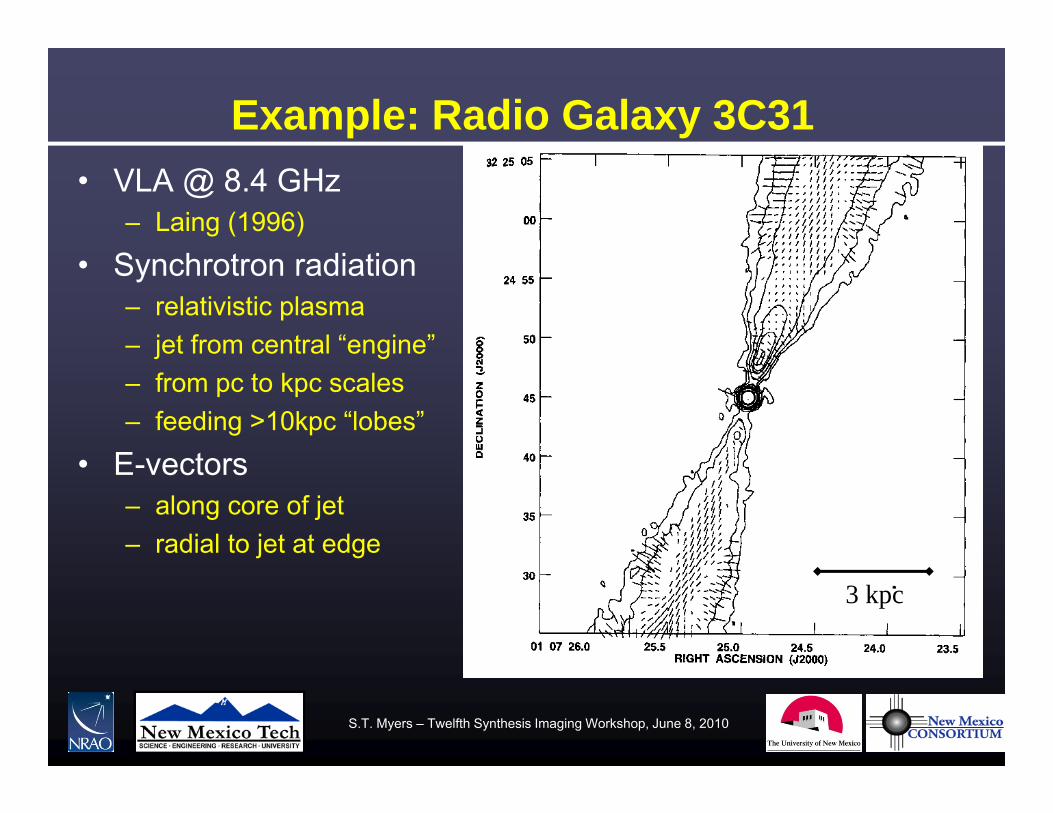
Example: Radio Galaxy 3C31• VLA @ 8.4 GHz
– Laing (1996)
S h di i• Synchrotron radiation– relativistic plasma– jet from central “engine”j g– from pc to kpc scales– feeding >10kpc “lobes”
E ectors• E-vectors– along core of jet– radial to jet at edge
3 kpc
S.T. Myers – Twelfth Synthesis Imaging Workshop, June 8, 2010
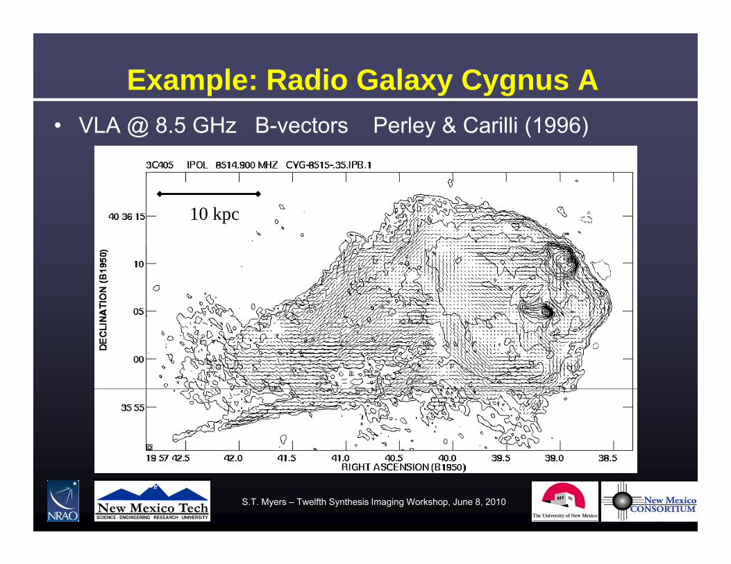
Example: Radio Galaxy Cygnus A• VLA @ 8.5 GHz B-vectors Perley & Carilli (1996)
10 kpc
S.T. Myers – Twelfth Synthesis Imaging Workshop, June 8, 2010
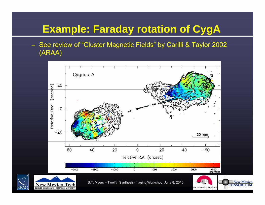
Example: Faraday rotation of CygA– See review of “Cluster Magnetic Fields” by Carilli & Taylor 2002
(ARAA)
S.T. Myers – Twelfth Synthesis Imaging Workshop, June 8, 2010

Example: Zeeman effect
S.T. Myers – Twelfth Synthesis Imaging Workshop, June 8, 2010

Example: the ISM of M51• Trace magnetic field
structure in galaxiesf ll i l t t– follow spiral structure
– origin?– amplified in dynamo?
Neininger (1992)g ( )
S.T. Myers – Twelfth Synthesis Imaging Workshop, June 8, 2010

Scattering• Anisotropic Scattering induces Linear Polarization
– electron scattering (e.g. in Cosmic Microwave Background)d t tt i ( i th illi t t )– dust scattering (e.g. in the millimeter-wave spectrum)
Planck predictions – Hu & Dodelson ARAA 2002
Animations from Wayne HuS.T. Myers – Twelfth Synthesis Imaging Workshop, June 8, 2010

Polarization Fundamentals
S.T. Myers – Twelfth Synthesis Imaging Workshop, June 8, 2010

The Polarization Ellipse• From Maxwell’s equations E•B=0 (E and B perpendicular)
– By convention, we consider the time behavior of the E-field in a fixed perpendicular plane from the point of view of thea fixed perpendicular plane, from the point of view of the receiver. 0 Ek
transverse wave
• For a monochromatic wave of frequency , we write
transverse wave
)φtπυ(AE)φtπυ(AE
yyy
xxx
2cos2cos
– These two equations describe an ellipse in the (x-y) plane. • The ellipse is described fully by three parameters:
A A d th h diff – AX, AY, and the phase difference, = Y-X.
S.T. Myers – Twelfth Synthesis Imaging Workshop, June 8, 2010

Elliptically Polarized Monochromatic WaveThe simplest descriptionof wave polarization is ina Cartesian coordinate frameframe.
In general, three parameters are needed to describe the ellipse.
If the E-vector is rotating:l k i i ‘L ft– clockwise, wave is ‘Left
Elliptically Polarized’, – counterclockwise, is
‘Right EllipticallyRight Elliptically Polarized’.
The angle atan(AY/AX) is used later equivalent to 2 independent Ex and Ey oscillatorsused later …
S.T. Myers – Twelfth Synthesis Imaging Workshop, June 8, 2010
equivalent to 2 independent Ex and Ey oscillators

Polarization Ellipse Ellipticity and P.A.• A more natural description is
in a frame (), rotated so the -axis lies along the major axis of the ellipsemajor axis of the ellipse.
• The three parameters of the ellipse are then:A : the major axis lengthA : the major axis lengthtan : the axial ratio : the major axis p.a.
cos2tan2tan
• The ellipticity is signed:
sin2sin2sincos2tan2tan
The ellipticity is signed: > 0 REP < 0 LEP = 0,90° Linear (=0°,180°)
= ±45° Circular (=±90°) = ±45 Circular (=±90 )
S.T. Myers – Twelfth Synthesis Imaging Workshop, June 8, 2010

Circular Basis• We can decompose the E-field into a circular basis, rather than a (linear)
Cartesian one:
AA ˆˆE– where AR and AL are the amplitudes of two counter-rotating unit
vectors, eR (rotating counter-clockwise), and eL (clockwise)
LLRR eAeA ˆˆ E
vectors, eR (rotating counter clockwise), and eL (clockwise)– NOTE: R,L are obtained from X,Y by =±90° phase shift
• It is straightforward to show that:
XYYXYXR AAAAA
1
sin221
22
22
XYYXYXL AAAAA sin221 22
S.T. Myers – Twelfth Synthesis Imaging Workshop, June 8, 2010
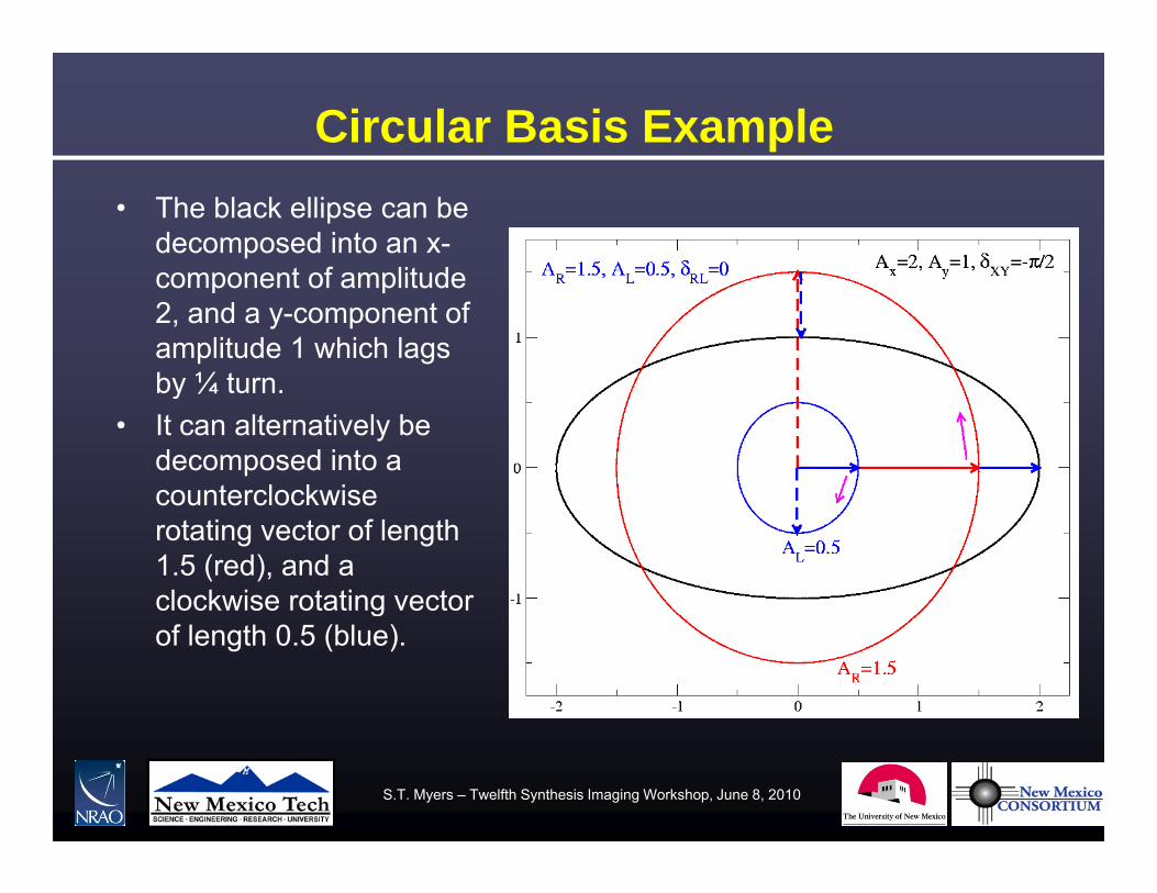
Circular Basis Example• The black ellipse can be
decomposed into an x-component of amplitudecomponent of amplitude 2, and a y-component of amplitude 1 which lags by ¼ turn.by ¼ turn.
• It can alternatively be decomposed into a counterclockwisecounterclockwise rotating vector of length 1.5 (red), and a clockwise rotating vector gof length 0.5 (blue).
S.T. Myers – Twelfth Synthesis Imaging Workshop, June 8, 2010
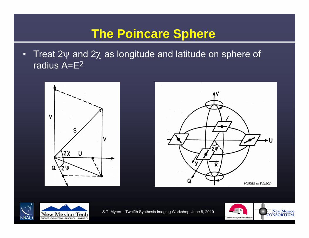
The Poincare Sphere• Treat 2 and 2 as longitude and latitude on sphere of
radius A=E2
Rohlfs & Wilson
S.T. Myers – Twelfth Synthesis Imaging Workshop, June 8, 2010
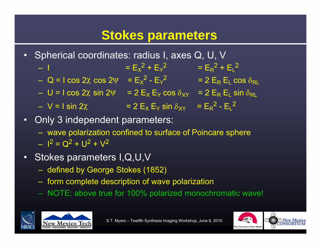
Stokes parameters• Spherical coordinates: radius I, axes Q, U, V
– I = EX2 + EY
2 = ER2 + EL
2
Q I 2 2 E 2 E 2 2 E E– Q = I cos 2 cos 2= EX2 - EY
2 = 2 ER EL cos RL
– U = I cos 2 sin 2= 2 EX EY cos XY = 2 ER EL sin RL
– V = I sin 2 = 2 EX EY sin XY = ER2 - EL
2 V I sin 2 2 EX EY sin XY ER EL
• Only 3 independent parameters:– wave polarization confined to surface of Poincare sphere
2 2 2 2– I2 = Q2 + U2 + V2
• Stokes parameters I,Q,U,V – defined by George Stokes (1852)defined by George Stokes (1852)– form complete description of wave polarization– NOTE: above true for 100% polarized monochromatic wave!
S.T. Myers – Twelfth Synthesis Imaging Workshop, June 8, 2010

Linear Polarization• Linearly Polarized Radiation: V = 0
– Linearly polarized flux: 22 UQP
– Q and U define the linear polarization position angle:
QU /2tan
UQP
– Signs of Q and U:
QU /2tan
Q > 0
Q < 0Q < 0
U > 0 U < 0
Q > 0
U > 0U < 0
S.T. Myers – Twelfth Synthesis Imaging Workshop, June 8, 2010

Simple Examples• If V = 0, the wave is linearly polarized. Then,
– If U = 0, and Q positive, then the wave is vertically polarized, =0°
– If U = 0, and Q negative, the wave is horizontally polarized, =90°
– If Q = 0 and U positive the wave is polarized at = 45°If Q 0, and U positive, the wave is polarized at 45
If Q 0 d U ti th i l i d t 45°– If Q = 0, and U negative, the wave is polarized at = -45°.
S.T. Myers – Twelfth Synthesis Imaging Workshop, June 8, 2010

Illustrative Example: Non-thermal Emission from Jupiter
• Apr 1999 VLA 5 GHz data• D-config resolution is 14” • Jupiter emits thermalJupiter emits thermal
radiation from atmosphere, plus polarized synchrotron radiation from particles in its
ti fi ldmagnetic field• Shown is the I image
(intensity) with polarization vectors rotated by 90° (tovectors rotated by 90 (to show B-vectors) and polarized intensity (blue contours)
• The polarization vectors trace Jupiter’s dipole
• Polarized intensity linked to th I l tthe Io plasma torus
S.T. Myers – Twelfth Synthesis Imaging Workshop, June 8, 2010
Why Use Stokes Parameters?• Tradition• They are scalar quantities, independent of basis XY, RL
Th h it f (fl d it h lib t d)• They have units of power (flux density when calibrated)• They are simply related to actual antenna measurements.• They easily accommodate the notion of partial polarization ofThey easily accommodate the notion of partial polarization of
non-monochromatic signals. • We can (as I will show) make images of the I, Q, U, and V
intensities directly from measurements made from anintensities directly from measurements made from an interferometer.
• These I,Q,U, and V images can then be combined to make i f th li i l lli ti l h t i ti fimages of the linear, circular, or elliptical characteristics of the radiation.
S.T. Myers – Twelfth Synthesis Imaging Workshop, June 8, 2010

Partial Polarization
• Monochromatic radiation is a myth. • No such entity can exist (although it can be closely
i d)approximated). • In real life, radiation has a finite bandwidth. • Real astronomical emission processes arise from randomly• Real astronomical emission processes arise from randomly
placed, independently oscillating emitters (electrons). • We observe the summed electric field, using instruments of g
finite bandwidth. • Despite the chaos, polarization still exists, but is not
complete partial polarization is the rulecomplete – partial polarization is the rule.
S.T. Myers – Twelfth Synthesis Imaging Workshop, June 8, 2010

Stokes Parameters for Partial PolarizationStokes parameters defined in terms of mean quantities:
2222lryx EEEEI
22
i22
cos2 rllryx
lryx
EEEEU
EEEEQ
22sin2
sin2cos2
lrxyyx
rllrxyyx
EEEEV
EEEEU
Note that now, unlike monochromatic radiation, the radiation is not necessarily 100% polarized.
2222 VUQI
S.T. Myers – Twelfth Synthesis Imaging Workshop, June 8, 2010
Summary – Fundamentals• Monochromatic waves are polarized• Expressible as 2 orthogonal independent transverse waves
– elliptical cross-section polarization ellipse– 3 independent parameters– choice of basis, e.g. linear or circular, g
• Poincare sphere convenient representation– Stokes parameters I, Q, U, V
I i t it Q U li l i ti V i l l i ti– I intensity; Q,U linear polarization, V circular polarization
• Quasi-monochromatic “waves” in reality– can be partially polarizedca be pa a y po a ed– still represented by Stokes parameters
S.T. Myers – Twelfth Synthesis Imaging Workshop, June 8, 2010

Antenna Polarization
S.T. Myers – Twelfth Synthesis Imaging Workshop, June 8, 2010
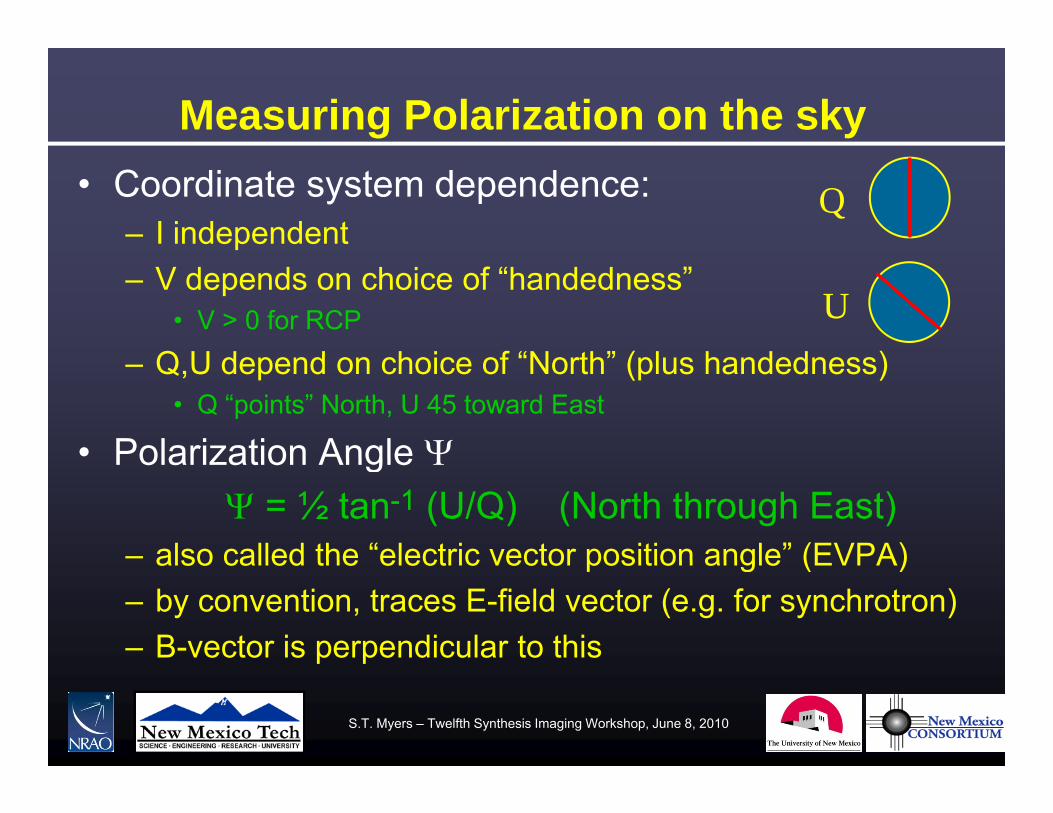
Measuring Polarization on the sky• Coordinate system dependence:
– I independentQ
– V depends on choice of “handedness”• V > 0 for RCP
Q U d d h i f “N th” ( l h d d )
U– Q,U depend on choice of “North” (plus handedness)
• Q “points” North, U 45 toward East
• Polarization Angle Polarization Angle = ½ tan-1 (U/Q) (North through East)
– also called the “electric vector position angle” (EVPA)also called the electric vector position angle (EVPA)– by convention, traces E-field vector (e.g. for synchrotron)– B-vector is perpendicular to thisp p
S.T. Myers – Twelfth Synthesis Imaging Workshop, June 8, 2010

Optics – Cassegrain radio telescope • Paraboloid illuminated by feedhorn:
Feeds arranged in f l l ( ff i )focal plane (off-axis)
S.T. Myers – Twelfth Synthesis Imaging Workshop, June 8, 2010
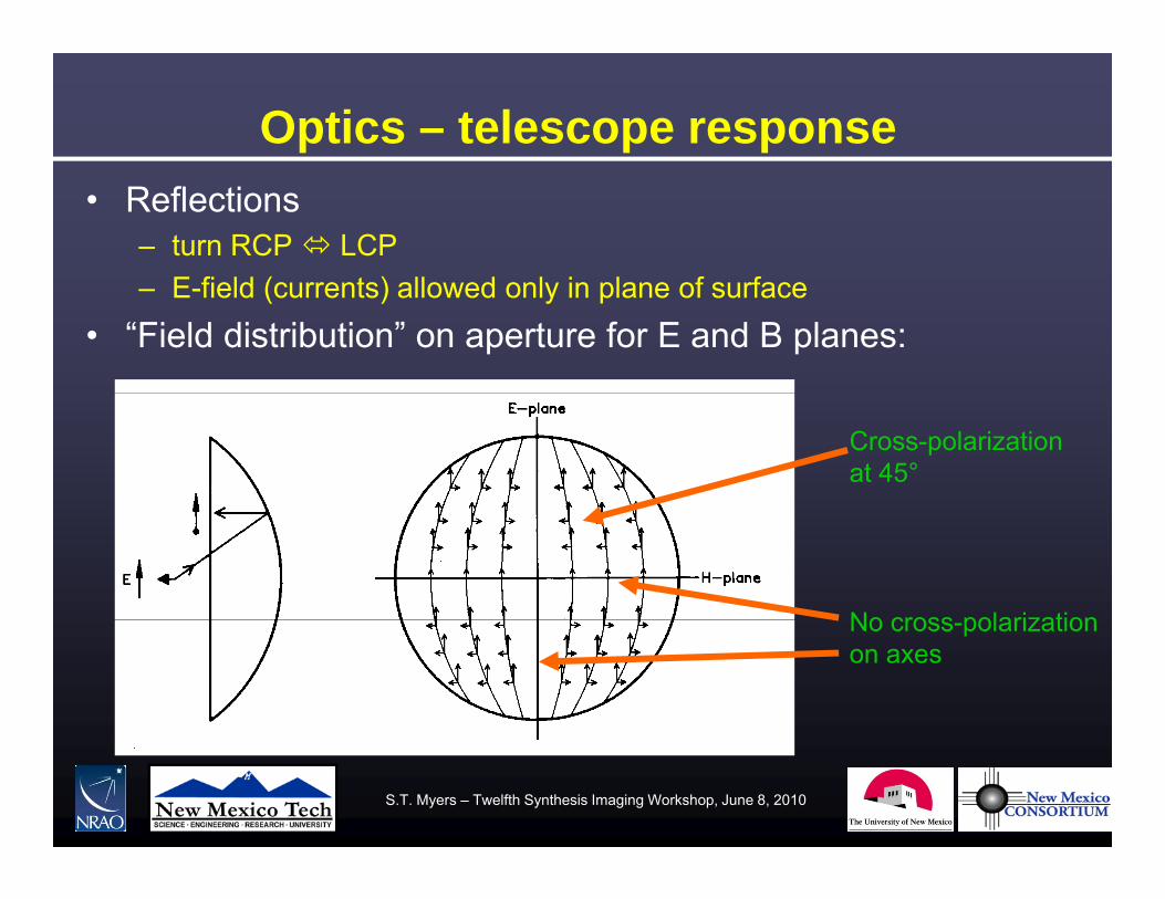
Optics – telescope response • Reflections
– turn RCP LCPE fi ld ( t ) ll d l i l f f– E-field (currents) allowed only in plane of surface
• “Field distribution” on aperture for E and B planes:
Cross-polarizationat 45°
No cross polarizationNo cross-polarizationon axes
S.T. Myers – Twelfth Synthesis Imaging Workshop, June 8, 2010

Example – simulated VLA patterns• EVLA Memo 58 “Using Grasp8 to Study the VLA Beam” W.
Brisken
Linear Polarization Circular Polarization cuts in R & L
S.T. Myers – Twelfth Synthesis Imaging Workshop, June 8, 2010
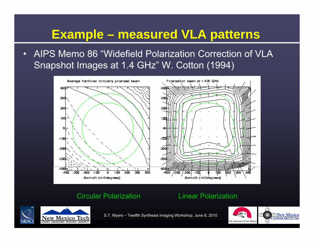
Example – measured VLA patterns• AIPS Memo 86 “Widefield Polarization Correction of VLA
Snapshot Images at 1.4 GHz” W. Cotton (1994)
Circular Polarization Linear PolarizationCircular Polarization Linear Polarization
S.T. Myers – Twelfth Synthesis Imaging Workshop, June 8, 2010

Polarization Reciever Outputs• To do polarimetry (measure the polarization state of the EM
wave), the antenna must have two outputs which respond differently to the incoming elliptically polarized wavedifferently to the incoming elliptically polarized wave.
• It would be most convenient if these two outputs are proportional to either:
The t o linear orthogonal Cartesian components (E E ) as in– The two linear orthogonal Cartesian components, (EX, EY) as in ATCA and ALMA
– The two circular orthogonal components, (ER, EL) as in VLASadly this is not the case in general• Sadly, this is not the case in general. – In general, each port is elliptically polarized, with its own polarization
ellipse, with its p.a. and ellipticity. H l th diff t l i t b• However, as long as these are different, polarimetry can be done.
S.T. Myers – Twelfth Synthesis Imaging Workshop, June 8, 2010
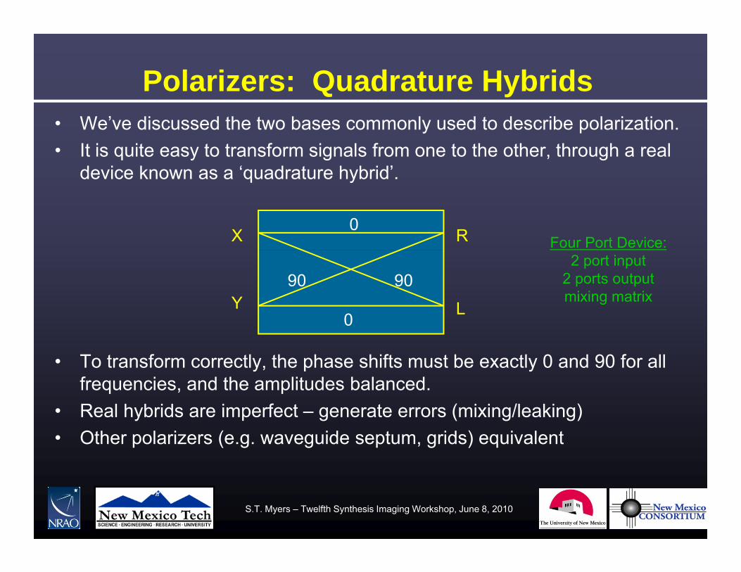
Polarizers: Quadrature Hybrids• We’ve discussed the two bases commonly used to describe polarization. • It is quite easy to transform signals from one to the other, through a real
device known as a ‘quadrature hybrid’.device known as a quadrature hybrid .
0X R Four Port Device:
0
90 90Y L
2 port input2 ports outputmixing matrix
• To transform correctly, the phase shifts must be exactly 0 and 90 for all frequencies, and the amplitudes balanced.
0
• Real hybrids are imperfect – generate errors (mixing/leaking)• Other polarizers (e.g. waveguide septum, grids) equivalent
S.T. Myers – Twelfth Synthesis Imaging Workshop, June 8, 2010

Polarization Interferometry
S.T. Myers – Twelfth Synthesis Imaging Workshop, June 8, 2010
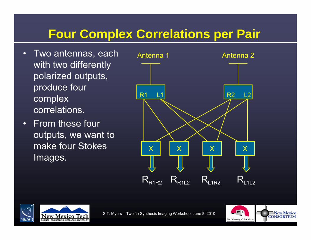
Four Complex Correlations per Pair• Two antennas, each
with two differently polarized outputs
Antenna 1 Antenna 2
polarized outputs, produce four complex L1R1 L2R2
correlations. • From these four
outputs we want tooutputs, we want to make four Stokes Images.
X X X X
RR1R2 RR1L2 RL1R2 RL1L2
S.T. Myers – Twelfth Synthesis Imaging Workshop, June 8, 2010

Outputs: Polarization Vectors
• Each telescope receiver has two outputs– should be orthogonal, close to X,Y or R,Lg , , ,– even if single pol output, convenient to consider
both possible polarizations (e.g. for leakage)– put into vector
)()( tEtE XR
)()(
)( or)()(
)(tEtE
tEtEtE
tEY
X
L
R
S.T. Myers – Twelfth Synthesis Imaging Workshop, June 8, 2010
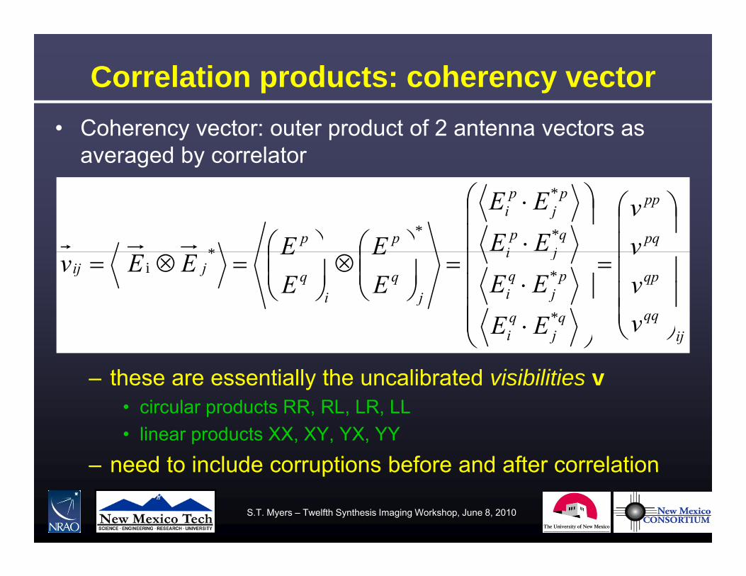
Correlation products: coherency vector• Coherency vector: outer product of 2 antenna vectors as
averaged by correlator
pq
pp
qj
pi
pj
pi
pp vv
EEEE
EE
*
*
**
qp
pj
qi
ji
jq
iqjij
vvv
EEEEE
EEE
EEv
*
**
i
– these are essentially the uncalibrated visibilities v
ijq
jqi vEE
• circular products RR, RL, LR, LL• linear products XX, XY, YX, YY
– need to include corruptions before and after correlationneed to include corruptions before and after correlation
S.T. Myers – Twelfth Synthesis Imaging Workshop, June 8, 2010

Polarization Products: General Case
)]sin()sin()cos()[cos(
)]sin()sin()cos()[cos({21
qpqpqpqp
qpqpqpqppqpq
iQ
iIGv
)]}cos()sin()sin()[cos(
)]cos()sin()sin()[cos(
)]()()()[ (
qpqpqpqp
qpqpqpqp
iV
iiU
Q
)]}cos()sin()sin()[cos( qpqpqpqp iV
What are all these symbols? vpq is the complex output from the interferometer, for polarizations
p and q from antennas 1 and 2, respectively. and are the antenna polarization major axis and ellipticity for
states p and q. I Q U d V h S k Vi ibili i d ibi h l i iI,Q, U, and V are the Stokes Visibilities describing the polarization
state of the astronomical signal. G is the gain, which falls out in calibration.
CONVENTION WE WILL ABSORB FACTOR ½ INTO GAIN!!!!!!!CONVENTION – WE WILL ABSORB FACTOR ½ INTO GAIN!!!!!!!
S.T. Myers – Twelfth Synthesis Imaging Workshop, June 8, 2010

Coherency vector and Stokes vector• Maps (perfect) visibilities to the Stokes vector s• Example: circular polarization (e.g. VLA)
iUQVI
QI
ivv
svLR
RL
RR
circcirc0101001
S
VIiUQ
VUi
vv
sv
LL
LRcirccirc
1001010
S
• Example: linear polarization (e.g. ALMA, ATCA)
QIIv
XY
XX 0011
QIiVUiVU
VUQ
ii
vvv
sv
YY
YX
XY
linlin
0011100100
S
QVv 00
S.T. Myers – Twelfth Synthesis Imaging Workshop, June 8, 2010

Corruptions: Jones Matrices• Antenna-based corruptions
– pre-correlation polarization-dependent effects act as a matrix muliplication This is the Jones matrix:muliplication. This is the Jones matrix:
11211 EE
JJEE
inoutJJ
form of J depends on basis (RL or XY) and effect
22221
E
EJJ
EE JJ
– form of J depends on basis (RL or XY) and effect• off-diagonal terms J12 and J21 cause corruption (mixing)
– total J is a string of Jones matrices for each effect
F d l i d b l k ll ti l
PDEF JJJJJ • Faraday, polarized beam, leakage, parallactic angle
S.T. Myers – Twelfth Synthesis Imaging Workshop, June 8, 2010
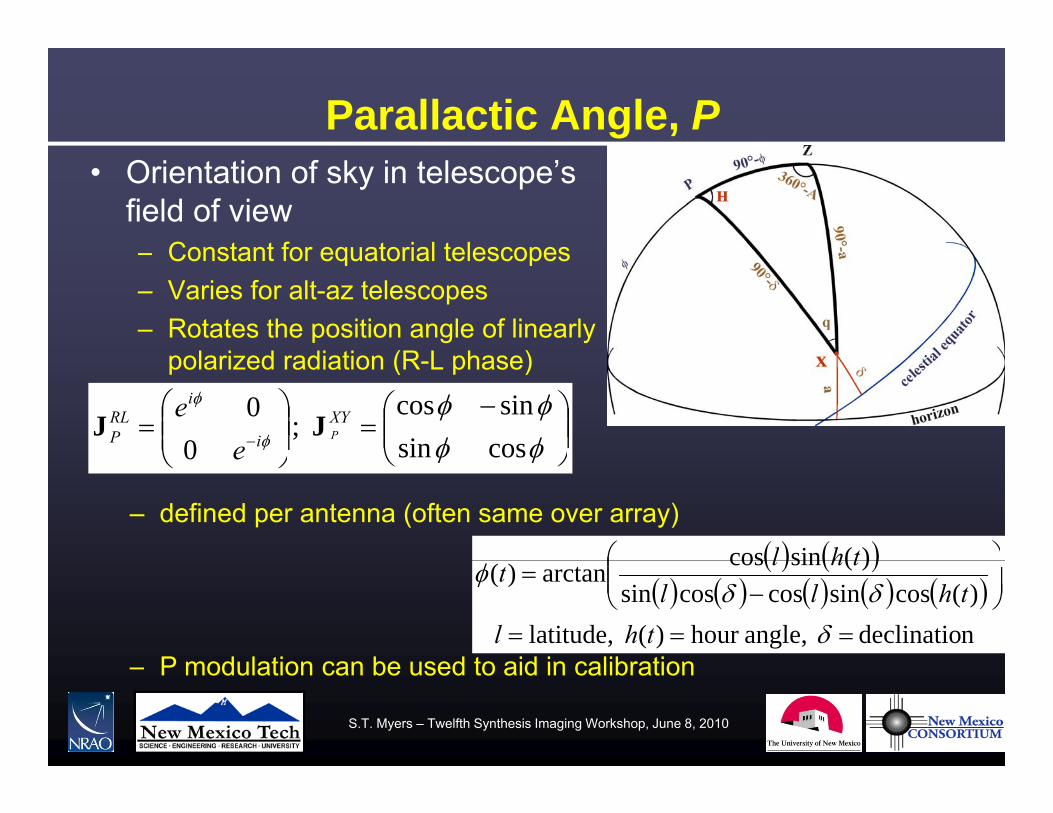
Parallactic Angle, P• Orientation of sky in telescope’s
field of viewConstant for equatorial telescopes– Constant for equatorial telescopes
– Varies for alt-az telescopes– Rotates the position angle of linearly
polari ed radiation (R L phase)polarized radiation (R-L phase)
cossinsincos
; 0
0 XYi
iRLP P
ee
JJ
)(sincos
thl
0 e
– defined per antenna (often same over array)
n declinatio angle,hour )( latitude,)(cossincoscossin
)(sincosarctan)(
thlthll
thlt
P modulation can be used to aid in calibration– P modulation can be used to aid in calibration
S.T. Myers – Twelfth Synthesis Imaging Workshop, June 8, 2010

Visibilities to Stokes on-sky: RL basis• the (outer) products of the parallactic angle (P) and the
Stokes matrices gives
• this matrix maps a sky Stokes vector to the coherence vector
sv P SJ• this matrix maps a sky Stokes vector to the coherence vector
representing the four perfect (circular) polarization products:
VIIiiRR )()(
eiUQeiUQ
VI
UQI
eieeie
ee
vvv
i
i
ii
ii
ii
LR
RL
RR
jijiji
jiji
jiji
2
2
)()(
)()(
)()(
0000
00
VIeiUQ
VU
eeeie
vv
iiLL jiji )()( 0000
Circular Feeds: linear polarization in cross hands circular in parallel handsCircular Feeds: linear polarization in cross hands, circular in parallel-hands
S.T. Myers – Twelfth Synthesis Imaging Workshop, June 8, 2010

Visibilities to Stokes on-sky: XY basis• we have
Iiv jijijiji
XX )sin()sin()cos()cos(
VUQ
ii
ivv
jijijiji
jijijiji
YY
YX
XY
)i ()i ()()()cos()cos()sin()sin(
)cos()cos()sin()sin(
• and for identical parallactic angles between antennas:
Viv jijijiji
YY )sin()sin()cos()cos(
XX
22i2cos2sin
2sin2cos
iVUQiVUQ
UQIvv
jiYX
XY
XX Linear Feeds:linear polarization
present in all hands
2sin2cos2cos2sin
UQIiVUQ
vv ji
YY
YX
circular polarizationonly in cross-hands
S.T. Myers – Twelfth Synthesis Imaging Workshop, June 8, 2010

Basic Interferometry equations• An interferometer naturally measures the transform of
the sky intensity in uv-space convolved with aperturel ti f t lt tt i l– cross-correlation of aperture voltage patterns in uv-plane
– its tranform on sky is the primary beam A with FWHM ~ /D
n)()()( )(22 pieIAdV xxuxxxxu
n)(~)(~n)()()(
22
p
p
i
p
eIAd
eIAdVxvvvuv
xxxxu
– The “tilde” quantities are Fourier transforms, with convention:
)()(
)()()()(~ 22 uxxxu xu vumlTedT i
)(~)(
),(),()()(22 uux
uxxxuxu TedT
vumlTedTi
S.T. Myers – Twelfth Synthesis Imaging Workshop, June 8, 2010
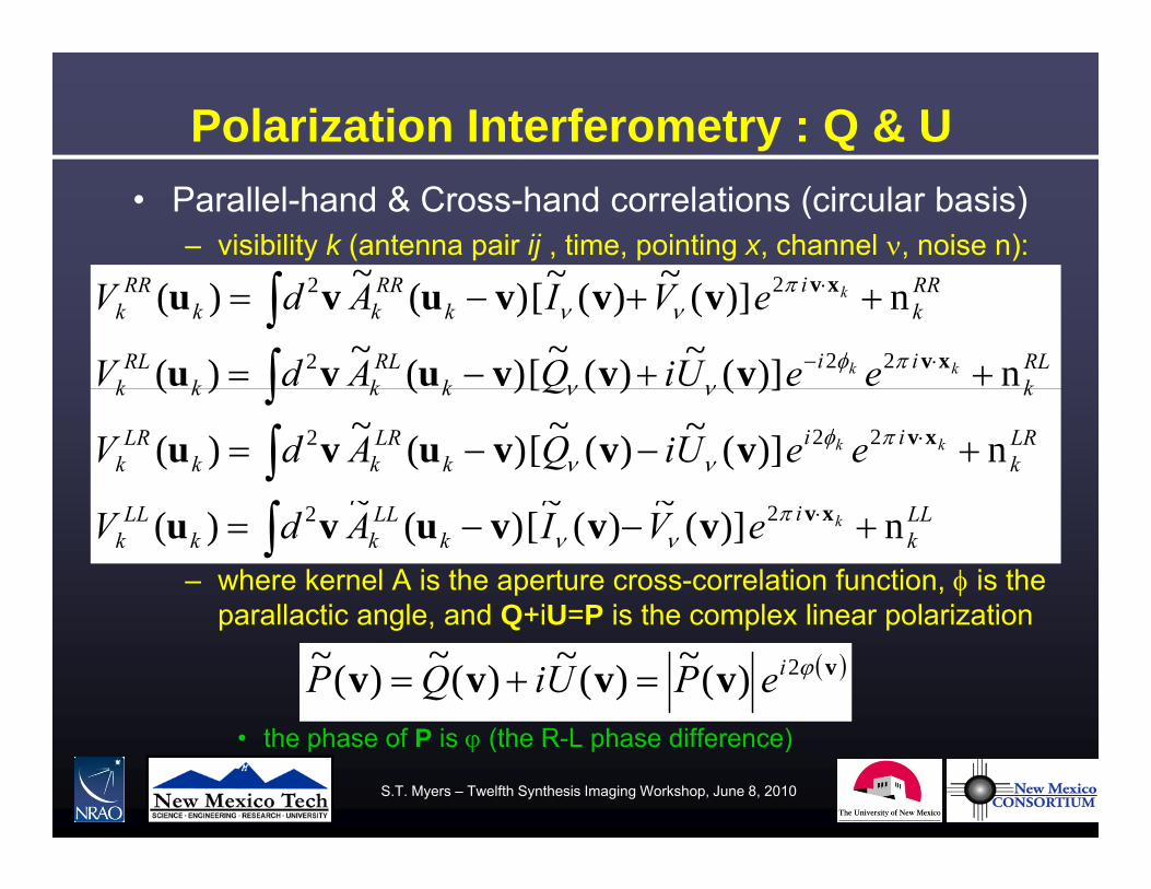
Polarization Interferometry : Q & U• Parallel-hand & Cross-hand correlations (circular basis)
– visibility k (antenna pair ij , time, pointing x, channel , noise n):~~~ 2
RLk
iik
RLkk
RLk
RRk
ik
RRkk
RRk
kk
k
eeUiQAdV
eVIAdV
n)](~)(~[)(~)(
n)](~)(~[)(~)(222
22
xv
xv
vvvuvu
vvvuvu
LRk
iik
LRkk
LRk
kkkkk
kk eeUiQAdV
Q
n)](~)(~[)(~)(
)]()([)()(222
xvvvvuvu
– where kernel A is the aperture cross-correlation function, is the parallactic angle and Q+iU=P is the complex linear polarization
LLk
ik
LLkk
LLk
keVIAdV n)](~)(~[)(~)( 22 xvvvvuvu
parallactic angle, and Q+iU=P is the complex linear polarization
vvvvv 2)(~)(~)(~)(~ iePUiQP • the phase of P is (the R-L phase difference)
S.T. Myers – Twelfth Synthesis Imaging Workshop, June 8, 2010

Example: RL basis imaging• Parenthetical Note:
– can make a pseudo-I image by gridding RR+LL on the Fourier half-plane and inverting to a real image
– can make a pseudo-V image by gridding RR-LL on the Fourier half plane and inverting to real imageFourier half-plane and inverting to real image
– can make a pseudo-(Q+iU) image by gridding RL to the full Fourier plane (with LR as the conjugate) and inverting to a complex image
– does not require having full polarization RR,RL,LR,LL for every visibility (unlike calibration/correction of visibilities)every visibility (unlike calibration/correction of visibilities)
• More on imaging ( & deconvolution ) tomorrow!
S.T. Myers – Twelfth Synthesis Imaging Workshop, June 8, 2010
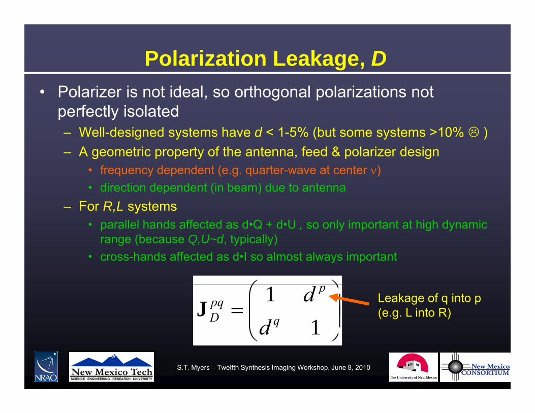
Polarization Leakage, D• Polarizer is not ideal, so orthogonal polarizations not
perfectly isolatedW ll d i d t h d 1 5% (b t t 10% )– Well-designed systems have d < 1-5% (but some systems >10% )
– A geometric property of the antenna, feed & polarizer design• frequency dependent (e.g. quarter-wave at center )• direction dependent (in beam) due to antenna
– For R,L systems• parallel hands affected as d•Q + d•U , so only important at high dynamic
range (because Q,U~d, typically)• cross-hands affected as d•I so almost always important
11
q
ppqD d
dJ Leakage of q into p
(e.g. L into R)
S.T. Myers – Twelfth Synthesis Imaging Workshop, June 8, 2010
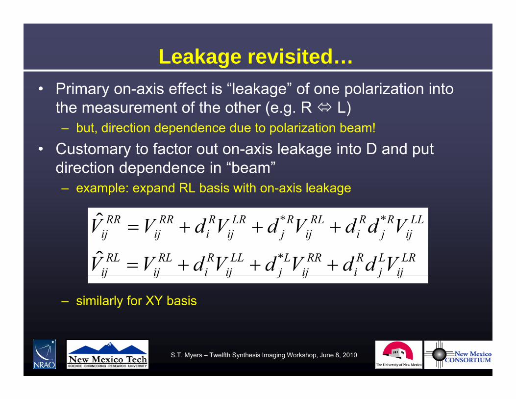
Leakage revisited…• Primary on-axis effect is “leakage” of one polarization into
the measurement of the other (e.g. R L)b t di ti d d d t l i ti b !– but, direction dependence due to polarization beam!
• Customary to factor out on-axis leakage into D and put direction dependence in “beam”p– example: expand RL basis with on-axis leakage
LLRRRLRLRRRRRR VddVdVdVV **ˆ
LRij
Lj
Ri
RRij
Lj
LLij
Ri
RLij
RLij
ijjiijjijiijij
VddVdVdVV
VddVdVdVV
*ˆ
– similarly for XY basis
ijjiijjijiijij
S.T. Myers – Twelfth Synthesis Imaging Workshop, June 8, 2010
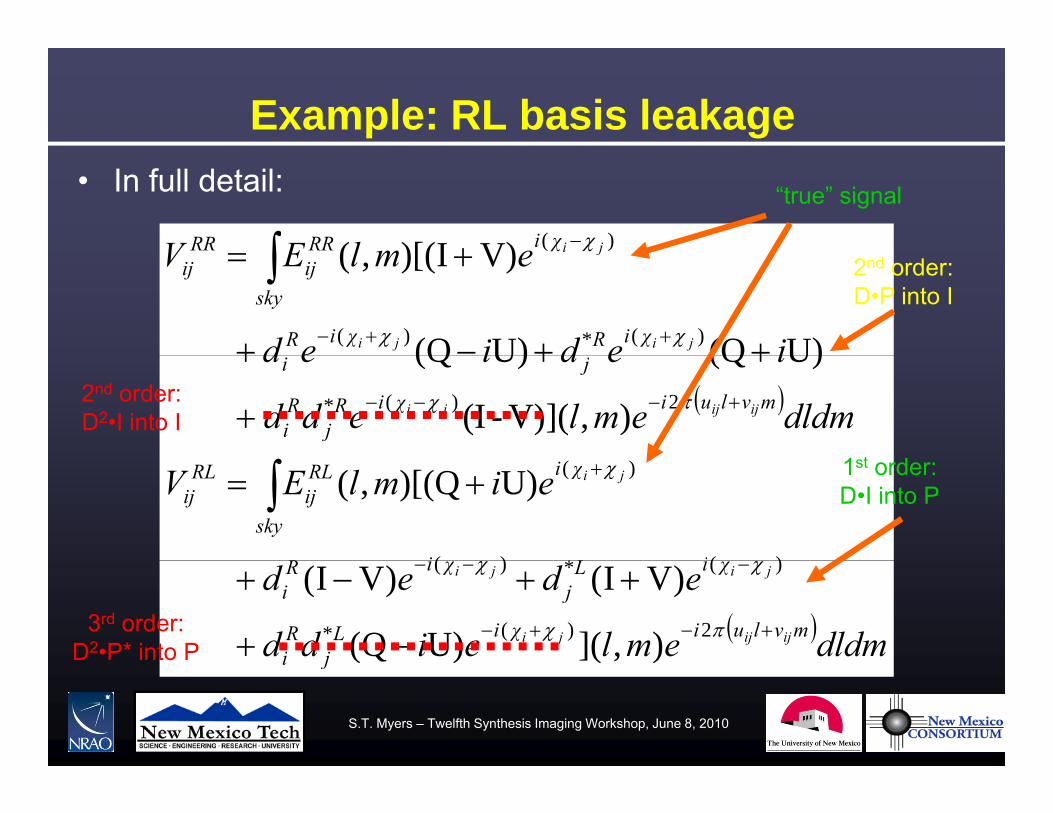
Example: RL basis leakage• In full detail:
emlEV χiRRRR ji )(V)I)[((
“true” signal
iedied
emlEV
χiRχiR
skyijij
jiji
j
)(*)( U)(QU)(Q
V)I)[(,( 2nd order:D•P into I
dldmemledd
iediedmvluiχiR
jRi
ji
ijijji
2)(* ),](V)-(I
U)(QU)(Q
1 t d
2nd order:D2•I into I
eimlEV
iLiR
χi
sky
RLij
RLij
ji
)(*)(
)(U)Q)[(,( 1st order:D•I into P
dldmemleidd
ededmvluiχiL
jRi
χiLj
χiRi
ijijji
jiji
2)(*
)(*)(
),](U)Q(
)VI()VI(3rd order:
D2•P* into P ji )()(
S.T. Myers – Twelfth Synthesis Imaging Workshop, June 8, 2010
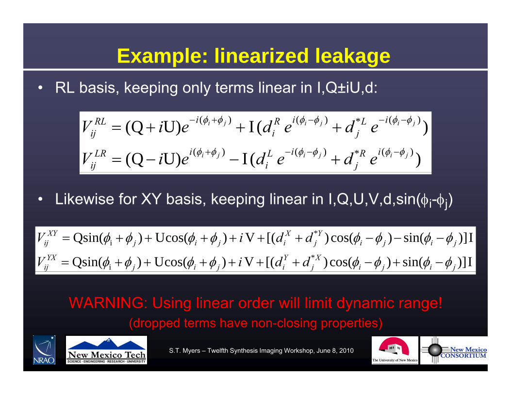
Example: linearized leakage• RL basis, keeping only terms linear in I,Q±iU,d:
)(IU)Q( )(*)()( jijiji iLiRiRL ddiV
)(IU)Q(
)(IU)Q()(*)()(
)()()(
jijiji
jijiji
iRj
iLi
iLRij
iLj
iRi
iRLij
ededeiV
ededeiV
• Likewise for XY basis, keeping linear in I,Q,U,V,d,sin(i-j)
I)]sin()cos()[(V)cos(U)sin(Q
I)]sin()cos()[(V)cos(U)sin(Q*
i
*i
jijiX
jYijij
YXij
jijiY
jX
ijijXY
ij
ddiV
ddiV
WARNING: Using linear order will limit dynamic range!(dropped terms have non closing properties)(dropped terms have non-closing properties)
S.T. Myers – Twelfth Synthesis Imaging Workshop, June 8, 2010

Ionospheric Faraday Rotation, F• Birefringency due to magnetic field in ionospheric plasma
0i
RLF
eJ
cossinsincos
0
XYF
iF e
J
J
cossin
is direction-dependent 15.0 ||
2 dsnB e
G;1~ ;cm10~ ||-214 BdsnTEC e
G)in ,cm10in cm,in ( ||2-14
||
Bdsne
e
– also present in ISM, IGM and intrinsic to radio sources!• can come from different Faraday depths tomography
60~ cm20
||
• can come from different Faraday depths tomography
S.T. Myers – Twelfth Synthesis Imaging Workshop, June 8, 2010

Antenna voltage pattern, E• Direction-dependent gain and polarization
– includes primary beam • Fourier transform of cross-correlation of antenna voltage patterns• includes polarization asymmetry (squint)
)()(),(),(
mlemlemlemle
qqqp
pqpppqEJ
– includes off-axis cross-polarization (leakage)
),(),(
mlemle qqqp
p ( g )• convenient to reserve D for on-axis leakage
– important in wide-field imaging and mosaicingh fill th b ( l f )• when sources fill the beam (e.g. low frequency)
S.T. Myers – Twelfth Synthesis Imaging Workshop, June 8, 2010
Summary – polarization interferometry• Choice of basis: CP or LP feeds
– usually a technology consideration• Follow the signal path
– ionospheric Faraday rotation F at low frequency• direction dependent (and antenna dependent for long baselines)• direction dependent (and antenna dependent for long baselines)
– parallactic angle P for coordinate transformation to Stokes• antennas can have differing PA (e.g. VLBI)
– “leakage” D varies with and over beam (mix with E)• Leakage
use full (all orders) D solver when possible– use full (all orders) D solver when possible– linear approximation OK for low dynamic range– beware when antennas have different parallactic anglesp g
S.T. Myers – Twelfth Synthesis Imaging Workshop, June 8, 2010

Polarization Calibration
& Observation
S.T. Myers – Twelfth Synthesis Imaging Workshop, June 8, 2010

So you want to make a polarization image…• Making polarization images
– follow general rules for imaging– image & deconvolve I, Q, U, V
e.g Jupiter 6cm continuum
planes– Q, U, V will be positive and
negative– V image can often be used as– V image can often be used as
check (if no intrinsic V-pol)• Polarization vector plots
– EVPA calibrator to set angle (e.g. g ( gR-L phase difference) = ½ tan-1 U/Q for E vectors
– B vectors ┴ E l t E t (l th i b P)– plot E vectors (length given by P)
• Leakage calibration is essential• See Tutorials on Friday
S.T. Myers – Twelfth Synthesis Imaging Workshop, June 8, 2010
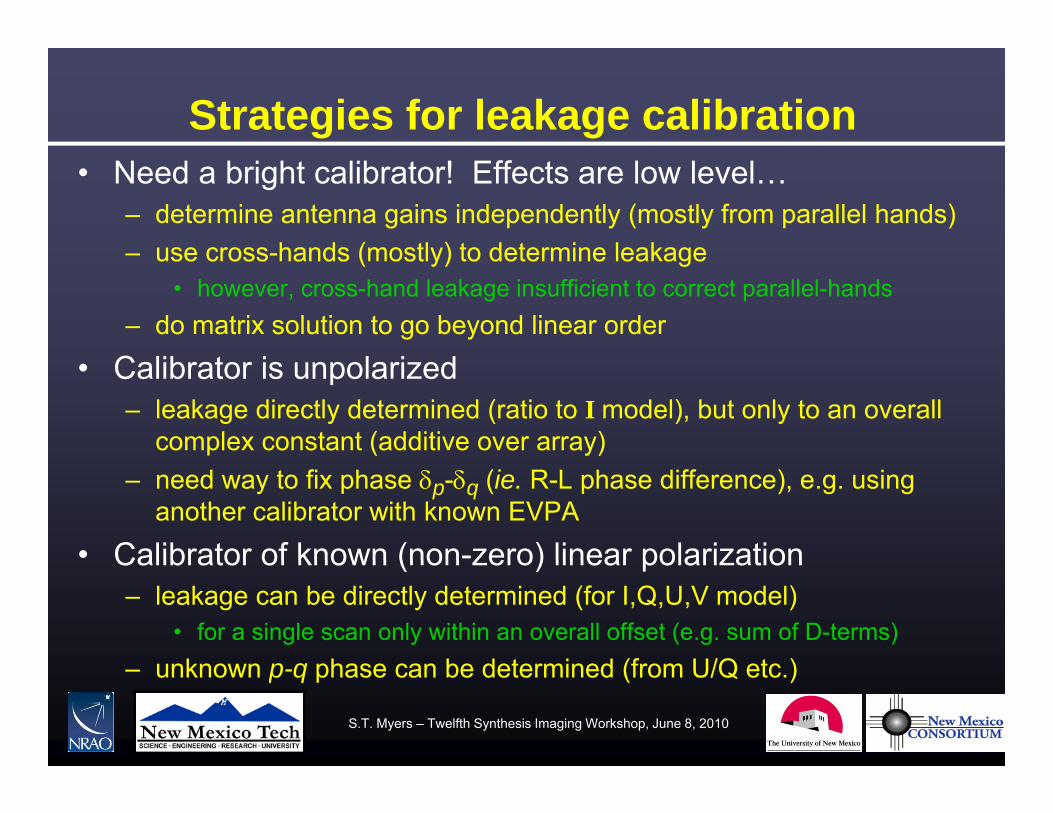
Strategies for leakage calibration• Need a bright calibrator! Effects are low level…
– determine antenna gains independently (mostly from parallel hands)use cross hands (mostly) to determine leakage– use cross-hands (mostly) to determine leakage
• however, cross-hand leakage insufficient to correct parallel-hands– do matrix solution to go beyond linear order
• Calibrator is unpolarized– leakage directly determined (ratio to I model), but only to an overall
complex constant (additive over array)– need way to fix phase p-q (ie. R-L phase difference), e.g. using
another calibrator with known EVPA
• Calibrator of known (non-zero) linear polarizationCalibrator of known (non zero) linear polarization– leakage can be directly determined (for I,Q,U,V model)
• for a single scan only within an overall offset (e.g. sum of D-terms)k h b d t i d (f U/Q t )– unknown p-q phase can be determined (from U/Q etc.)
S.T. Myers – Twelfth Synthesis Imaging Workshop, June 8, 2010

Other strategies• Calibrator of unknown polarization
– solve for model IQUV and D simultaneously or iterativelyd d ll ti l t d l t k d– need good parallactic angle coverage to modulate sky and
instrumental signals• in instrument basis, sky signal modulated by ei2
• With a very bright strongly polarized calibrator– can solve for leakages and polarization per baseline– can solve for leakages using parallel hands!can solve for leakages using parallel hands!
• With no calibrator– hope it averages down over parallactic angle– transfer D from a similar observation
• usually possible for several days, better than nothing!• need observations at same frequency
S.T. Myers – Twelfth Synthesis Imaging Workshop, June 8, 2010

Parallactic Angle Coverage at VLA• fastest PA swing for source passing through zenith
– to get good PA coverage in a few hours, need calibrators between declination +20° and +60°dec a o 0 a d 60
S.T. Myers – Twelfth Synthesis Imaging Workshop, June 8, 2010
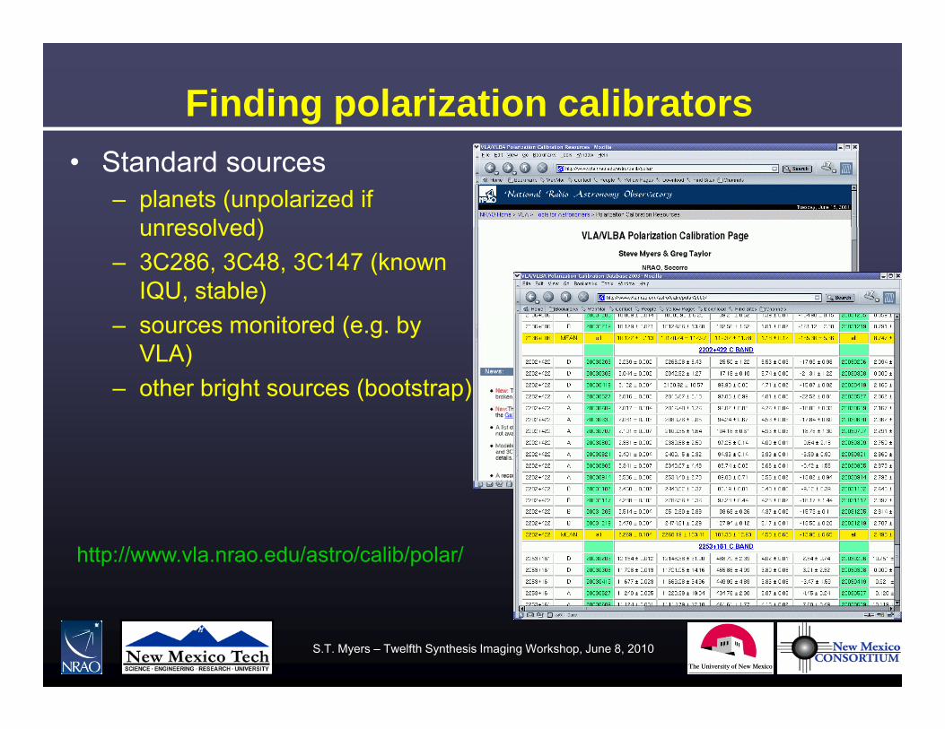
Finding polarization calibrators• Standard sources
– planets (unpolarized if unresolved)unresolved)
– 3C286, 3C48, 3C147 (known IQU, stable)
it d ( b– sources monitored (e.g. by VLA)
– other bright sources (bootstrap)
http://www.vla.nrao.edu/astro/calib/polar/
S.T. Myers – Twelfth Synthesis Imaging Workshop, June 8, 2010

Example: VLA D-term calibration• D-term calibration effect on RL visibilities (should be Q+iU):
S.T. Myers – Twelfth Synthesis Imaging Workshop, June 8, 2010
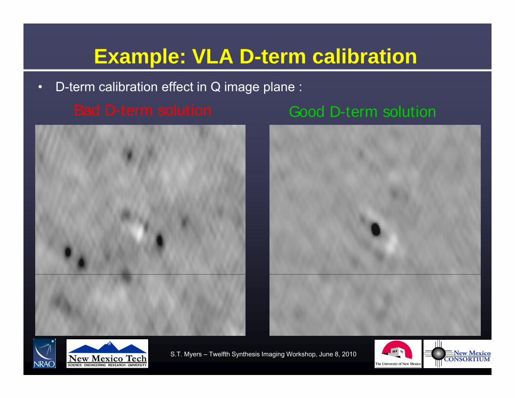
Example: VLA D-term calibration• D-term calibration effect in Q image plane :
Bad D-term solution Good D-term solution
S.T. Myers – Twelfth Synthesis Imaging Workshop, June 8, 2010

Example: EVLA D-term calibration• C-band D-term calibration as a function of frequency (OSRO-1 mode):
– frequency-dependent effects over wide bands, beware of cross-hand delays
EA19
S.T. Myers – Twelfth Synthesis Imaging Workshop, June 8, 2010
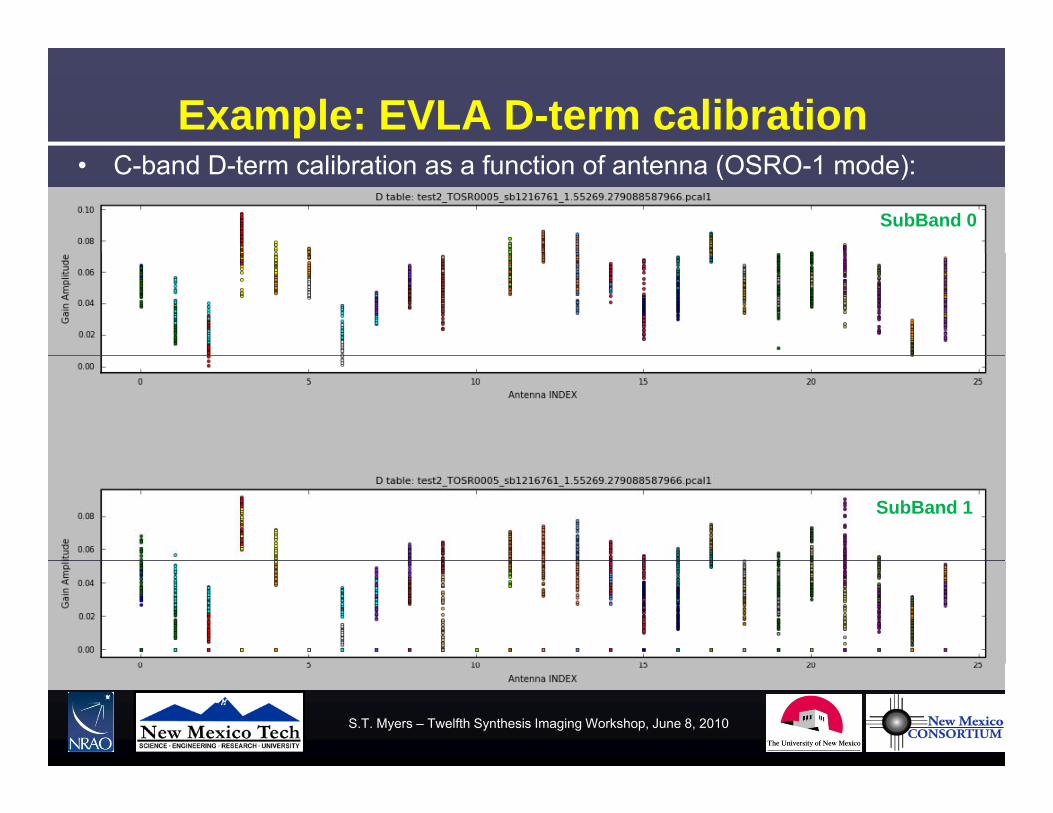
Example: EVLA D-term calibration• C-band D-term calibration as a function of antenna (OSRO-1 mode):
– frequency-dependent effects over wide bands, beware of cross-hand delaysSubBand 0
EA19
SubBand 1
S.T. Myers – Twelfth Synthesis Imaging Workshop, June 8, 2010

Example: EVLA EVPA calibration• C-band R-L phase as a function of frequency (OSRO-1 mode):
– solve for single-phase and cross-hand delay over array
EA19SubBand 0
EA19SubBand 1
S.T. Myers – Twelfth Synthesis Imaging Workshop, June 8, 2010
Summary – Observing & Calibration• Follow normal calibration procedure (see next lecture)• Need bright calibrator for leakage D calibration
– bright calibrator with known polarization– unpolarized (or very low polarization) sources see only leakage
• Parallactic angle coverage usefulParallactic angle coverage useful– necessary for unknown calibrator polarization
• Need to determine unknown p-q phase– CP feeds need EVPA calibrator (known strong Q,U) for R-L phase– if system stable, can transfer from other observations
• Upshot – build polarization calibration into scheduleUpshot build polarization calibration into schedule– if you need PA coverage, will be observing near zenith– watch antenna wraps (particularly in dynamic scheduling)!
S.T. Myers – Twelfth Synthesis Imaging Workshop, June 8, 2010
Special Considerations – EVLA & ALMA• Wideband calibration issues
– D-term and p-q phase corrections as function of frequencyd b i ht t l h l b i– need bright source to solve on per-channel basis
• Delay issues– parallel-hand delays taken out in bandpassp y p– need to remove cross-hand delays in or before Pol calibration
• High-dynamic range issuesD t t ib ti t ll l h d l ti ( l i )– D-term contribution to parallel-hand correlations (non-closing)
– wide-field polarization imaging/calibration algorithm development• direction-dependent voltage beam patterns needed
• Special issues– EVLA circular feeds: observing V difficult– ALMA linear feeds: gain calibration interaction– ALMA linear feeds: gain calibration interaction
S.T. Myers – Twelfth Synthesis Imaging Workshop, June 8, 2010