STERLING POWER PRODUCTS ADVANCED ... Number: PDARW Part Number:PDARRC 2 x temp sensors 1 for battery...
54
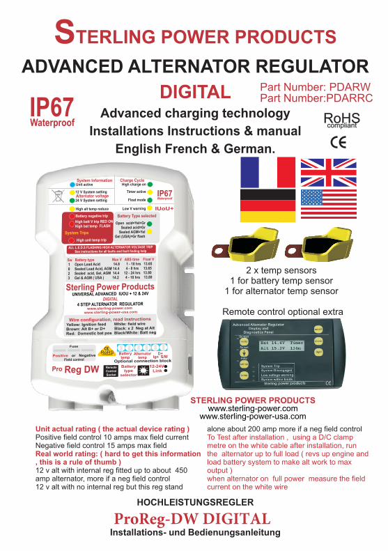
Part Number: PDARW Part Number:PDARRC 2 x temp sensors 1 for battery temp sensor 1 for alternator temp sensor Remote control optional extra RoHS compliant STERLING POWER PRODUCTS DIGITAL ProReg-DW DIGITAL ADVANCED ALTERNATOR REGULATOR Advanced charging technology Installations Instructions & manual English French & German. HOCHLEISTUNGSREGLER Installations- und Bedienungsanleitung STERLING POWER PRODUCTS www.sterling-power.com www.sterling-power-usa.com Unit actual rating ( the actual device rating ) To Test after installation , using a D/C clamp metre on the white cable after installation, run Real world rating: ( hard to get this information the alternator up to full load ( revs up engine and , this is a rule of thumb ) load battery system to make alt work to max output ) when alternator on full power measure the field current on the white wire alone about 200 amp more if a neg field control Positive field control 10 amps max field current Negative field control 15 amps max field 12 v alt with internal reg fitted up to about 450 amp alternator, more if a neg field control 12 v alt with no internal reg but this reg stand IP67 Waterproof
Transcript of STERLING POWER PRODUCTS ADVANCED ... Number: PDARW Part Number:PDARRC 2 x temp sensors 1 for battery...
Part Number: PDARW Part Number:PDARRC
2 x temp sensors1 for battery temp sensor
1 for alternator temp sensor
Remote control optional extra
RoHScompliant
STERLING POWER PRODUCTS
DIGITAL
ProReg-DW DIGITAL
ADVANCED ALTERNATOR REGULATOR
Advanced charging technology
Installations Instructions & manual
English French & German.
HOCHLEISTUNGSREGLER
Installations- und Bedienungsanleitung
STERLING POWER PRODUCTSwww.sterling-power.com
www.sterling-power-usa.com
Unit actual rating ( the actual device rating )To Test after installation , using a D/C clamp metre on the white cable after installation, run
Real world rating: ( hard to get this information the alternator up to full load ( revs up engine and , this is a rule of thumb ) load battery system to make alt work to max
output ) when alternator on full power measure the field current on the white wire
alone about 200 amp more if a neg field control Positive field control 10 amps max field current Negative field control 15 amps max field
12 v alt with internal reg fitted up to about 450 amp alternator, more if a neg field control12 v alt with no internal reg but this reg stand
IP67Waterproof
UNIVERSAL DIGITAL ADVANCED REGULATOR FITTING INSTRUCTIONS.
This new unit is suitable for 12 and 24V operation, obviously to set this unit up as 24V on a 12V system, would be catastrophic and all effort is made to ensure this does not happen. The unit comes preset to 12V operation as standard, a small electrical bridge must be made in order for the 24V function to be operated ( see later for this information). This bridge is not supplied in the regulator box but is Sellotaped to the centre of these instructions ensuring that it cannot accidentally be installed. For 24V installation please ensure you fit this bridge. .
Quick fit
Normal installationAlternator to Battery charger Battery to Battery charger
Thank you for purchasing one of the most advanced and powerful alternator regulator currently available in the world today. Please do not underestimate the effect this device will have on a conventional charging system. It is important to understand that your existing cables and layout may not be up to dealing with the extra performance from the alternator. You’ll ( for knowledgeable and need to ensure your alternator cables can deal experienced regulator fitters only ) Remove with the actual rating of the alternator and the the alternator. Locate the 2 alternator brushes, cable run lengths. Be warned about dash connect a 5-10A cable to each brush ( solder or mounted ammeters as they inevitably cause screw fix depending on the alternator ) about 200 excessive cable runs and extra resistance in the mm long. Replace the alternator to where it was. cable. Use shunt type ammeters to help Run up the alternator, measure the voltage of the eliminate this effect. The Advanced Regulator 2 wires to earth, ( ensure there is at least 14V has many safety devices built in to protect your coming out of the alt to confirm it still works ). If system from damage in the event of the you get the following: 0V on one wire and 2-12V installation being unable to handle the extra on the other wire then this is a Positive field performance caused by this device. The software control alternator. Keep the 2-12V wire and will pick most problems and disengage the unit secure/remove the 0V wire. If you get about 14V and give a warning. The advanced regulator will on one wire and 2-12V on the other then this is a then automatically revert back to your standard Negative field control alternator. Keep the 2-12V regulator, reducing the performance but getting wire and remove/secure the 14V wire. Connect all you home. the other wires as per the wiring diagram. Leave
the white wire free (this is the field control wire) Advanced alternator regulators, by their very when all other wires are connected then select design, will increase the output voltage from the the correct alternator field wire settings and the alternator, they are superb at doing this in older battery type (as per the instructions see quick installations on boats and even some vehicles reference guide to select the correct settings ). and they cause no problems. However, where When the unit has the correct settings the engine has an ECU ( electronic control programmed then connect the field wire, that it management system ) this can cause alarms to all. be generated by the engine management system. For modern engines and vehicles look
: see later for at the Sterling’s
actual instructions ( to be used for non- or the
experienced fitters and D.I.Y. customers) units as they will achieve the same
enhanced alternator / battery charging This device in most cases is not difficult to install, performance but will not touch the vehicle’s if a logical, step-by-step approach is maintained. primary system and not cause ECU or warranty Please note: There will be extra help notes on problems. www.sterling-power.com and should be used in
events of any problems.
Unit actual rating ( the actual device rating )
Real world rating: ( hard to get this information, this is a rule of thumb )
If possible it is wise to test the max field current test after installation. Using a DC clampmeter on the white cable after installation, runthe alternator up to full load ( rev up engine and load battery system to make alt work to max output ). When alternator is on full power measure the field current on the white wire. If the units specifications is exceeded then it will simply overheat and shut down, it should not damage the unit.
Positive field control 8A max field current Negative field control 13A max field
12V alternator with internal regulator fitted up to about 300A alternator. More if a negative field control.12V alternator with no internal regulator but this regulator stand alone can handle about 100A on positive and about 150A more if a negative field control.
Some basic tools, a voltmeter and soldering equipment are required for installation. This is the only hard part and this will also The new regulator has been made to be totally determine your alternator type, when you have flexible for all battery and alternator types. It is identified the alternator type please fill in the important for you to collect the following space above. Because there are so many information about your system. This will enable alternators and many are not identifiable, the you to set the regulator correctly and obtain the installation instructions apply to all alternators.maximum results from the device.Please obtain the following information about your The most important thing is to identify is the field system and fill in the space provided, if nothing control wire. This is the key wire which controls else it is about time you knew this information. the operation of all alternators: To fit this product
you will require a basic knowledge in the following skills:1) Using basic tools and removing alternators from the engine.2) basic DC electrics on vehicles / boats or whatever the engine is on.3) basic soldering as you may be required to
Alternator Type: There are two alternator types: solder some small wires.negative and positive rotor field control. Do not 4) basic understanding of the electrical worry at this stage, which you have, but it is vital management system on the engine ( i.e is there that you identify the correct one before connecting a complex ECU Electronic Control Unit ) in the advanced regulator. This will be dealt with which case the advanced regulator would not later. be the correct product. You should be looking My alternator type is: at a Alternator to battery charger or a
Battery to battery charger which are non invasive products and do not affect the
Battery Type: There are four main battery types: engine’s primary electrical system.all the settings for these 4 battery types are 5) If there is a warranty issue with fitting this clearly marked on the Advanced Regulator label. product, if the engine is new, then again we There is a lot of conflicting settings for gel and would recommend you change the product to A.G.M. we have shown the setting recommended the Battery to Battery charger as this by Exide ( the major gel manufacturers ). does not touch the basic engine’s system and, However, there are other companies who as such, would not affect the warranty of the disagree with this in the USA. So, we have a engine’s system. If the boat is over 4 years old in setting for them also. It is best to check with your most cases the above warranty issues do not battery supplier. apply.Battery Type selector ( fig 1 ) If you are worried or uncomfortable about 1) Conventional lead acid batteries, where you any of the above basic skills required, then have access to the liquid level to maintain and top either employ a professional to install the up the batteries. These may be charged at a product or use the Sterling Alternator to faster rate and as such, the high charge setting battery charger / Sterling Battery to battery may be used. By far the fastest charging batteries charger. They are more expensive but much and the lowest cost. Open lead acid/ traction more simple to fit.batteries are the best type for fast charging and long life.
batteries, not so good for fast charging as cannot replace the water loss associated with fast charging. As such the top voltage is reduced to reduce the water loss,3) Gel batteries ( Exide setting ) require, 14.4V 10-12 hours on the charge voltage to charge them, as recommended by Exide.4) Gel USA settings 14.1V.
The new software in the digital regulator automatically calculates the battery bank size, charge state and alternator output. Then, the internal DIGITAL processor sets the timing sequence every time you start the engine.
Install field wire on alternator:
Alternator Voltage (12V or 24V type).....................VOLTS Alternator Current (35A, 55A etc)....................AMPS
(Neg or SterlingPos)......................... Sterling
Sterling
14.8V max for up to 8 hours.
14.4V max 4-6 hrs
2) Sealed Lead acid and some A.G.M

LED alarms and indicators
1) Blue:
STOP as soon as possible 2) Yellow:
and disconnect the alternator wires. Then continue on your journey and fix the problem
3) Green: at the first opportunity. Sterling are unable to defend you against this fault other than warn
4) Yellow you as it is on your basic system over which we have no control. Failure to react to this problem will result in your batteries boiling.
( For 24V x all voltages by 2)
5) Red:
6) Red
(For 24V x all voltages by 2 )Flashing L.E.D ( For 24V x
Solid redall voltages by 2 )
exceeds 15.5V. There are three things that can cause this.
1) The alternator’s own regulator has failed indicates there is power on the unit to
closed, if the voltage continues to climb after the operate it, if there is no LED on then check
trip light has come on then the alternator’s own voltage on yellow ignition feed, must be voltage
regulator is usually to blame (or there is an there 12-24V.
installation fault). Shows the product is set for 12V alternator
operation.Shows the product is set for 24V alternator
operation.High Alternator temperature disengage:
This shows that the alternator temperature sensor has exceeded 90 degrees C and has automatically disengaged the Advanced Regulator. The regulator
2) The Advanced Regulator’s own regulator will automatically re-engage at 65 degrees C. This
has failed closed. process is fully automatic and requires no
If the battery voltage returns to 14V after the trip intervention. If you find this trip working a lot of the
light has gone off then the Sterling Regulator has time, I suggest you check your engine room cooling
failed and the unit should be returned for and I would recommend a fan cooling system,
repair/replacement as soon as possible. It is, blowing cold air from outside onto the back of the
however, still safe to use in an emergency case alternator (alternators suck air from the back through
only, as when the batteries are flat the unit will themselves to the front).
charge them to 15.5V and then switch off. It Battery Negative Trip Fault: This alarm shows
should be stressed that this is for emergency, get that there is a fault on the negative between the
me to port use only!battery negative and the alternator negative. This is
3) Some other charging source has failed, usually due a bad connection. Please clean all
I.e. the battery charger/wind generator /solar connections and check cable crimps etc
panels etc. In this case, the voltage would Dual Information LED: This LED has two
continue to rise even when the engine is functions and as such, has two display modes.
switched off. Display Mode 2: .
Display Mode 1: LED on indicates a This indicates that the
high battery voltage trip, suggesting that the voltage temperature sensor has picked up the battery
1
2
3
410
8
11
9
5
12
13
Fig 1
67
14
temperature exceeding 50 degrees C. This usually reasons such as cables from the alternator to the means that the battery is defective and on it’s way to battery are too long and not thick enough to boiling. Check the voltage across the battery, if below carry the current or, if there is an ammeter in the 14V and 50 degrees C then the battery is defective. circuit then usually there is a problem with the Replace as soon as possible. connections to the ammeter. If an installation has
High unit temperature trip. been running satisfactorily for a period of a few High Charge Rate On: (top LED 1) This weeks and this starts then check if the split
should be on from start up and shows that the charge relay or diode is okay and has not failed. alternator should be working at it’s maximum. It should Please note that when this, or any trip light is on remain on until LED 3 comes on and shows the high the Advanced Regulator has been electrically charge rate is over. totally isolated from the alternator and is no
Timer Activated: This comes on when the longer in use.voltage reaches about 13.9 - 14V and depending on how long it takes to come on, the software will calculate the timing for the high charge rate. This will vary from 1 - 6 hours and the time will be displayed on the remote panel and a count down shown. This light will remain on until the high charge rate light goes out.
Float Mode: This indicates that all the high charge cycles are now over and should remain on after all the high charge lights are out. The system is now running at a standard charge rate only (about 14V) regulated on the battery.
Low Voltage Warning: This is simply saying that there is a low voltage at the main battery bank and has no active function. For information only, An alternator field type selector, this usually indicates a defective alternator. can be positioned in negative or positive field
Battery chemistry type indicator combined control position, ensure correct position is with 13. selected before activating product.
chemistry type indicator combined with 12.
Temperature sensors, 2 of, One for battery temperature and one for alternator temperature. Product will work without these being fitted and default to 20 deg C operation, but would lose the functions associated with the sensor.
The most common fault, this shows the alternators voltage has exceeded 17.5V (or 37V in the case of 24V). This happens for various
7) Red 8) Green
9) Yellow If the alternator voltage continues to rise after this has tripped then please check the alternator’s own regulator and stop and disconnect the alternator.
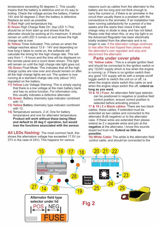
Parts under cover plate 14) Yellow cable :
10) Green
11) Yellow
15 & 16 ) Fuse:
12) Green
13) Yellow 17 & 19 ) 2 x Black cables:
14)
All LEDs flashing:
Battery
This is a simple ignition feed and should be connected to the ignition switch or any 12/24V supply which is live when the engine is running i.e. if there is no ignition switch then any good 12V supply will do with a simple on/off toggle switch to switch the unit on or off, i.e. when the engine starts switch this cable on and when the engine stops switch this off, extend as long as you want.
There are two black cables, these cables, if extended must be extended as two cables and connected to the alternator B-(B negative) or to the alternator case. If these wires are extended then please extend as 2 x separate wires and join at the negative at the alternator, I know this sounds stupid but trust me. Extend as little as possible.
The white is the alternator field control cable, and should be connected to the 18) White Cable:
FUSE
POS NEG
Alternator field typeselector under lid
29
RemoteControlSocket
Positive or NegativeField control
Fuse
65 74 8
3 92 01
14
15 1716 18
19
22
23
2120
2627 2524
28
Fig 2

field wire you fitted to the alternator earlier. This wire can be connected or disconnected with the alternator running, there may be cases where the Advanced Regulator needs to be switched off (i.e. small engine on a boat and a fast current) the Regulator has been known to knock off 1.5 knots of small boats with a 10-15 hp engine, however, most people usually connect and disconnect this cable (out of curiosity) to see the difference the Advanced Regulator makes to their system (with the Pro Digital, this unit can be switched on and off using the remote control). Extend as little as possible
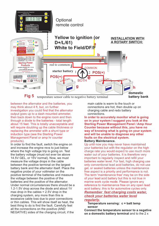
The red is the sense wire, wherever it is placed on the Regulator and will regulate the voltage of that spot, therefore, it is important that the end of the red cable and the alternator must never be isolated when the engine is running.The position of the red wire varies depending on what your charging system is:
; If your alternator charging circuit has a split charge diode fitted, position the sense on the battery side of the diode, on the side with the largest battery bank, (in the event of only two identical batteries either side will do).
: Same as above, however, be warned, most low cost relays in the marine industry are approx 25 mm cubed, these relays may have been good enough for your old poor charging system, but when an Advanced Regulator is used do not be surprised if after a short period of time the relay melts. Only use good relays.
Most yachts are fitted with a rotary switch, i.e. a switch with battery 1, battery 2, and both. With this type of charging system, position the sense on the back of the switch on the common point, remember that the only batteries to be charged are then dictated by you i.e. 1 or 2 or both. Due to the limitations and the constant changing of the switch, it would be my personal recommendation that, at a later date, you separate the charge line from the common starter feed and charge through a split charge diode.Boats that have their bow thrusters positioned some distance away from the two main battery banks should place the battery sense wire (red) at the main battery bank and not at the bow thrusters. This is because the increase in battery voltage caused by the excessive distance between the battery banks can be too much for the main battery to deal with. The bow thrusters' battery will still benefit from the Advanced Regulator even if the sense wire is placed at the main
23) 12-24V link, WARNING
do not fit this if a 12V alternator installation this will cause serious damage to you batteries and system. 24) Rotary battery chemistry selector
20) Battery Temperature sensor connector block. switch.
Split charge diode
Split charge relays
Rotary switch:21) Alternator temperature sensor connection block. 22) D+ disconnect
everything is okay. So, although the standard regulator sends out the warning signal, the Sterling system blocks its transmission to the dash and we take over the motoring. In the event of a fault we then disengage and show any faults.
This sensor is the same type and configuration as the alternator temperature sensor, however, it should be warning given.placed on the battery terminal on one of the batteries in the domestic battery bank, as this is the battery bank most likely to have the lower life expectancy. The idea behind temperature sensing is to monitor the battery temperature and reduce the charger voltage as the battery temperature rises due to either high ambient temperature, excessive installation in the battery box or a battery failure. In the event of the first two then the output voltage of the alternator will be reduced to prevent any unnecessary heat rise, however, in the event of a battery cell failing add the battery exceeding 50 Deg C then an alarm will be transmitted to the remote panel (if used) and the LED number 5 (red) will flash on the local panel will come on.
Most alternators have an ignition warning light on their dash (the light which comes on when the ignition is switched on and then the light switches off when the engine starts and the alternator starts to work). In the event of the alternator failing in most circumstances the ignition warning light will come on warning the operator of a fault with the alternator. Some modern alternators bring this feature a little further (the Butec and some of the new magnetic Merellie alternators, less than 0.1% of alternators used) have a new feature, this is that in the event of the standard alternator’s own regulator failing then it also switches on the ignition warning light to show a fault in the system. The problem with this is that when an Advanced Alternator Regulator is used then the alternators voltage is increased (by the Advanced Regulator) the standard regulator thinks it has failed and sends out the signal. This makes the operator think there is a problem. The D+ circuit disengages the ignition warning light after checking that
25) Remote control socket 26) Red Cable:
This is a fatal shutdown and can only be overridden by switching the engine off and on again. Always find out the cause of this alarm condition, do not simply reset the system and carry on regardless as this will cause excessive gassing and a possible fire. The same safety protocol is built into this system as above, if you do not wish to use this sensor, or, in the event of it becoming broken, then the software will pick up the fault and shut down its function and revert to a safe 20 deg C default setting.
D+ disengage:
by adding link this unit will become 24V alternator operation,
used to adjust the internal parameters for different battery chemistries

battery bank. alternator is a positive alternator field control; there is a special therefore, change the booster setting from
sense connector on the Sterling unit for this cable. negative to positive. (CONNECT THE This BROWN WIRE TO THE D+/61 /L TERMINAL,
connects to the main domestic battery bank THE REST AS PER STANDARD). The best negative rail. This cable measures the negative at advice is to use this alternator as a sea the battery banks, and checks it to the true anchor, and buy a decent size alternator, a negative at the alternator and ensures there is not 35A high revving alternator is no use to to big a voltage drop in the negative cables. Any anyone.voltage drop in excess of 1.5V will trigger an alarm and shut down the Advanced Regulator on high negative volt trip. Extend as long as you want
The brown goes to the D+ on the back of the alternator, this is the small cable which is usually marked on the alternator case as “D+” or “ING” or “ L” or “61” it is the cable which feeds the warning light on the dash. Connect the brown to the same terminal leaving the existing cable in place
b) Remote regulators, some alternators have regulators fitted remotely and connected to the alternator via 3-5 small 1) Isolate the engine battery (to prevent any wires (usually on old alternators), advice: The accidents with live cables), have a friend close by wires are still connected to a brush box on in case of any accidents or help is required. The the alternator, remember it is the brushes we advanced regulator should be fitted in a cool dry are after, locate the brushes as per normal. well ventilated space, if in an engine room then low Replace the regulator after the wires have down is a little cooler.been connected. This regulator can be used 2) Remove all the wires from the back of the with alts up to about 120A without a reg or up alternator (note down on this sheet as you go to 300A alts with an existing reg. through the instructions to ensure correct c) Yanmar and Hitachi alternators require placement of the regulator setup switches).the alternator case to be split (unbolted, not 3) With all the cables removed and taped up so hit with a sledgehammer), this will reveal the they cannot short out against the engine block brushes in the back part. Please note for remove the alternator ( for Bulmar / or other reassembly the two small holes in the brush alternators with remote regulators it may not be housing which enable a wire to hold the necessary to remove the alternator, read on ).brushes up when trying to reassemble the 3) With all the cables removed and taped up. To alternator.ensure they cannot short out against the engine 5) Having found the brushes solder a 100mm block remove the alternator.length of 10A cable to the top of each brush.4) Not so bad? Now for the hard bit. We are trying Problems: Lucas regulator connectors are to get to the two brushes, which supply the rotor its made from stainless steel and, as such, current; they are usually connected to the normal pre-fluxed solder is no use. Use regulator. The brushes are a replaceable item so standard plumbers flux from a tub and the there is some way of getting to them and removing solder will stick with no problem.them. Remove the regulator from the back of the 6) Having connected a cable to each brush, alternator (usually 2 or 4 screws holding a reassemble the alternator, reinstalling the component onto the back of the alternator) when unit’s own regulator (if it has one) and replace this is removed the regulator should come away it on the engine.with the brushes attached. This should be no Problems: Volvo engines with Valeo problem for about 80% of you with Lucas, Bosch, alternators require some cutting around the Volvo, however, the following things could be regulator seal. Use your common sense, different:never nip wires between the regulator and A) A brushless alternator, most common S.E.V. the alternator case. Marshell 35A alternator fitted to old Volvo/Buch 7) Ensure the ends of the two new cables are engines, has special instructions. On the alternator not touching each other, the alternator, or the regulator is an F or D/F connection, this is the field engine, and reconnect the alternator.wire, i.e. where the WHITE wire goes. This
On the
Other special instructions relate to the very old Bosch mechanical regulator (about 25 years old), this must not be used in conjunction with the Sterling Regulator, however, conduct the tests as above, you will find the alternator is a positive field control. When the correct field wire is obtained set the Advanced Regulator to positive and remove the old Bosch regulator this is not a common
some modern alternators have no D+ in this thing. Please look further on in these case connect to the B+ (the main positive output). instructions which show how an alternator extend as little as possible works, this information is enough to work out
, use for alternator what you need to do if you have an alternator or battery temperature sensing. with no regulator attached.
Sterling Pro Split R
28) Brown wire
29) Temperature sensors x 2
Lets begin the installation
27) Black Cable with white stripes.

8) After the alternator is reconnected, run the the battery type you require, select for the engine as normal, battery type table on ( will be confirmed
I.e. the ignition warning light by LEDs later ).on the dash should go out when the alternator is charging, as per normal.
You should have established what the alternator field type is by now, it should be a negative or positive field control, ensure you have the correct information.To set the alternator type, see . for negative, the fuse should be inboard of the edge of the case, if a positive unit then it 9) This is the most important part. With the should be the other way.engine running, well on tick over, using the There is a standard automotive 15A fuse in the voltmeter, we require the voltage from both the regulator, there are three legs which will hold cables you have just fitted to negative:that fuse. The fuse should come standard set Cable 1 = ..............volts cable 2 =...............volts to the negative position. In order to convert the (Also make a note of the alternator’s output voltage Regulator to a positive remove the fuse and while doing these tests, If the alternator is working re-position it in the other slot. see then we would expect to see a voltage of between
. 13-14V. if below 13V then the alternator is not working, if above 14.5V then the alternator’s own regulator is defective or one of the wires you have connected have shorted to the negative.
If the voltage on any of the cables is between 2-12V The software in the new Digital Regulator and the other is 14V then this is a negative rotor automatically calculates the equalizing time control, go to the pre-installation section and write cycle every time the engine is started. This will range between 1-12 hours depending on If the voltage on any of the cables are 1-11V and the the rise time between engine on and time to other is 0V, the alternator is a positive rotor control reach 14V; this will be different every time the go to the pre installation section and write engine is started and varies from battery type (For reference only, 90% of alternators in Europe are setting. The internal computer software will negative, these include Bosch, Valeo (Volvo), Hitachi look after this function if the sense wire is (Yanmar), Lucas. The only positive alternators tend to placed at the main battery bank.be old alternators with remote regulators and
American alternators such as Motorola and AC Delco (this information is to be used as a rough guide only).In either case, we keep the 1-11V cable and either Start the engine up as usual, the green boost remove or cut the 14 or 0V cable. (Ensure this cable light and the float light (yellow or green cannot touch the alternator case). depending on booster settings) should be on 10) Having found the field wire and identified the (the green boost light will flash for 2 mins on alternator type the hard work is over, now to install start up to show the slow start, this is to the regulator. reduce belt slip). The battery voltage should Remember to replace the old regulator back into the be measured to ensure the voltage works its alternator, do not leave it out. way up to 14.4/14.8V depending on the
settings. This could take between 1 minute and many hours depending on the battery bank size.1) By now you should have completed the pre-
The voltage may vary slightly from installation section. I will take you through the alternator i.e. +/- 0.1 of a volt.Regulator set up and also explain what you are
doing.2) Remove the lower lid by removing the screw and lift the lid off. Inside you will see the configurations as in on the drawing. You will see a fuse which has 2 possible positions: See . Number which is the fuse and number which is the rotary battery type selector switch.
Rotate the rotary switch ( ) to select
ensure the alternator is fig3working as standard.
WARNING: ensure you select the correct battery type and check the voltage, getting this wrong can damage your batteries.WARNING: GO NO FURTHER IF THE
ALTERNATOR IS NOT WORKING. Alternator Type:
WARNING: GO NO FURTHER IF THE ALTERNATOR IS NOT WORKING. The alternator must be in normal working mode
fig 2before continuing i.e. giving out about 14V from the output of the alternator.
fig 2 15 for pos and 16 for negative field control Failure to get this right will result in damage to the advanced regulator and maybe the alternator's standard regulator.
For Alternator Type:EQUALIZING TIME CYCLE:
NEG.
POS
Testing the system:
Set Up Advanced Regulator Before Installation
A word of warning, the most likely fault (assuming the Regulator is correctly connected) will be the high alternator voltage trip warning (all lights flashing). fig 2This is a unique safety device to fig 2 15 & 16 prevent you setting fire to your boat. 24The trip consists of two sensors; one is sensing the battery voltage and will trip Battery Type: 24
I will say again for people who think I am joking!

j
h Te
mp
era
ture
sen
so
r
f l
a = yellow to ignition (or D+/L/61)b = white to fieldc = brown to alt D+/62/L/DLd = 2 x black to alternator neg.e = split charge diode / relayf = alternatorg = starter batteryh = domestic battery banki = red to domestic batteryj = black/white to battery negativek = temperature sensor to alternatorl = temperature sensor to battery
a
b
g
id
e
Fig 4
POS(+)POS(+)
a = gelb an Zündung+ oder (D+/R/L/DL)b = weiss = Feldc = braun an D+/62/L/DLd = 2 x schwarz an Lima negativ-minuse = Trenndiode oder Relaisf = Lichtmaschineg = Starterbatterieh = Verbraucherbatteriebanki = rot an plus der Referenzbatteriej = schwarz-weiss an minus der Referenzbatteriek = Temperatursensor für die Lichtmaschinel = Temperatursensor der Referenzbatterie
INSTALLATON WITH SPLIT CHARGE DIODE OR RELAY:
k
INSTALLATON MIT TRENNDIODE ODER RELAIS:
Temperature-Sensor
c
if the batteries exceed 15.5V (this will only usually poor cable connections, long cable happen if the standard voltage regulator on the runs or too thin a cable to carry the current alternator is defective or the Advanced now being produced, or, simply a failure in Regulator is defective). The other sensor is the connection between the alternator and connected to the alternators D+ (the brown the batteries. A significant cause is an inline wire), this trips the Regulator if the voltage ammeter. Please be aware of cable runs with exceeds 17.5V at the alternator (all LEDs will ammeters in the system. A good question to flash together). The reasons for this tripping are ask yourself is what is the cable length
1 O Yellow + green 14.8 1 - 10 hrs 13.65 0 Sealed Lead acid + Gel = Green 14.4 12 - 24 hrs 13.85 2 Sealed lead acid + AGM = Yellow 14.4 4 - 8 hrs 13.60 3 Gel & AGM ( USA ) = Green Flash 14.2 4 - 10 hrs 13.80
Switch position Battery type( switch setting ) Max charge V ABS time Float V LEDspen lead acid =
Battery chemistry setting selection rotate switch x 2 for 24V( on fig 2 ) 24
fig 3
FUSE
POS NEG
Alternator field typeselector under lid
between the alternator and the batteries, you may think about 4 ft, but, on further investigation you could find that the alternator output goes up to a dash mounted ammeter, then back down to the engine room and then In order to accurately monitor what is going through a diode to the batteries - total length on in your system I suggest you look at the about 15 feet. This is totally unacceptable and Sterling Power Management Panel / Amp Hour will require doubling up the cable thickness or Counter because without this, you have no replacing the ammeter with a shunt type or way of knowing what is going on your system induction type (see the Sterling Power and will be unable to diagnose any other Management Panel or amp hr counter faults on the electrical system.products).
Up until now you may never have maintained your batteries but with the regulator on the high charge rate you would expect to use much more water out of your batteries. It is therefore very important to regularly inspect and refill your batteries water level. For fast, high charging use only conventional lead acid batteries, do not use gel, or sealed batteries unless the maintenance free aspect is a priority and performance is not. The term 'maintenance free' may be on the side of your lead acid battery but this is not true in marine work cycle mode. Please ignore any reference to maintenance free on any open lead acid battery; this is for automotive cycles only. Remember fast charging costs water, check your batteries water level regularly.
main cable is warm to the touch or connections are hot, then double up on charging cable and redo battery connections.
Battery Maintenance.In order to find the fault, switch the engine on and increase the engine revs to just below where the high voltage trip is going on. Test the battery voltage (must not ever be above 14.5V GEL, or 15V normal). Now, we must measure the voltage drops in the cable between the positive terminal on the largest battery bank and the alternator itself. Place the negative probe of your voltmeter on the positive terminal of the batteries and measure the voltage between the positive of the batteries and the positive of the alternator. Under normal circumstances there should be a 1.2-1.5V drop across the diode and about 1V max drop in the cables = 2.5V drop in the charging system, any more than this is excessive cable loss due to poor connections or thin cables. This will show itself as heat, the Temperature sensing: c = batt temp best thing to do is find the fault. Carefully feel sensorall the connections on the positive (AND NEGATIVE) sides of the charging circuit, if the and to the 2 x
Connect the temperature sensor to a negative on a domestic battery terminal
temperature sensor cable to negative battery terminal
starter battery
red to common
POS(+)
domesticbattery bank
1 2
COMMON
BOTH
INSTALLATION WITH A ROTARY SWITCH:a
bf
g
j
cd
e
h
Fig 5
POS(+)
light
CE
on/off
beep
1234
2
4
3
1
Power Managementwith
AMP Hr Counter
Sterling power products
Amphr
Amps Volts
14.35 v m Pos 437amps 435 a/hrs
Advanced Alternator RegulatorDisplay and
Diagnostics Panel
Sterling power products CE
on/off
alarm
light
temp
System
Default
Low voltage warning
System Disengaged
System Trip
System Within Limits
Screen
Help
Bat 14.4v TimerAlt 15.4v 134m
set up
volts
Yellow to ignition (or D+/L/61)White to Field/DF/F
Optional remote control

terminals inside the Regulator (see internal drawing) and extend the cables as required. There is no polarity to these cables so connect anyway round.
The new Advanced Regulator has in built temperature compensations based on the graphs supplied by the battery manufactures.There are three graph types programmed into the software and are automatically selected with the battery type choice. There is also an alarm/shut down function in the event of catastrophic failure of the batteries or the Advanced Regulator, it may be left off if not required or fitted. This device will reduce the charge voltage as the battery temperature increases and switches off the Regulator and gives an LED alarm in the event of the batteries over heating. This function is good in the following conditions.
All other trips are catered for electrically, remember this will only trip the Sterling Advanced Regulator, your standard regulator could continue to boil the batteries in the event of a bad battery fault or a standard regulator fault. The Sterling can only look after problems relating to the Sterling system.
In the event of a defective Sterling Regulator or standard regulator the batteries will start to overheat, the Regulator will pick this up and shut down the Sterling Regulator only, it cannot shut down the standard regulator in the event of it failing closed, however, the alarm function will be on.False readings: the temperature sensor is designed to fit on the battery terminal post to pick up the electrolytic temperature inside the battery case. In the event of the post having bad connections of very high current flow, the post may increase in temperature due to electrical resistance caused by bad connections, which could result in misleading temperature readings by the sensor. This would result in the Regulator shutdown with no fault with the batteries, a simple visual check and touching the battery case and battery terminals should establish if the electrolyte and the terminal are the same temperature or the terminal is much hotter than the electrolyte, in which case, the problem could be bad electrical connections at your battery.
Other new features on this unit:Dash warning light, some new alternators have a high voltage warning built into their alternator’s regulators, this switches on the ignition warning light in the event of fitting the Advanced Regulator (the Advanced Regulators higher voltage control makes the standard regulator think that it has failed).
MARINE ALTERNATOR WITH THIS PROBLEM (ON SOME FORD ENGINES) AND ONLY A FEW AUTOMOTIVE
The product will work without the ALTERNATORS WITH THIS. SO PLEASE temperature sensor fitted but will default to a 20 PHONE BEFORE ASSUMING THIS IS A Deg C ambient setting for battery charging curves. PROBLEM.
A) Defective battery:
B) Defective Regulator:
One of the limitations of battery temperature sensing is that you could have 6 batteries and 1 sensor.
WARNING: TO DATE, THERE IS ONLY 1
A small relay is built into the Regulator to disengage the D+ warning when the alternator has started up. This was a special function for a special vehicle where Sterling Power Products had a demand, however, it may become more common in the future.
Helpful hints how to find the Faults indicated by the LEDs For this you need a voltmeter
Fault on panel: All lights flashing.High alternator voltage trip.
A new installation where the advanced regulator has just been installed and so far has not worked correctly
Once all these lights flash what has happened is the alternator voltage sensed via the brown wire on the D+ has exceeded 17.5V ( x 2 for 24V ) and the advanced regulator has disconnected itself.Remember that when any red warning lights comes on, the Sterling has 100% disconnected itself ( it has a built in relay connected to the white wire ). So, the most important thing to check here is that, when this alarm comes on, whether or not the system reverts back to its own standard voltage ( or in the event of its own regulator not being used the alternator should cease functioning ). This is the most important thing to establish, because, if the alarm lights on and the Advanced Regulator has disconnected itself, then the standard system should automatically take over and automatically drop the charger voltage back to the standard voltage setting ( about 14V at the alternator ), if this does not happen and the voltage continues to rise then the standard alternator system is at fault.There are a number of reasons for the high alternator trip activating, and it falls into 2 main headings:
1) Due to the incorrect handling of the standard regulator, when installing the field cables, the standard regulator has failed closed. The only solution for this is to replace the standard regulator. 2) The solder you put onto the brush to connect the field wire to has to touch the alternator case and caused the field to go to earth ( on negative field control only ) or the

cable you connected has been nipped to the alt case when bringing the cable outside the alternator. To test for this, using a voltmeter, turn the meter to Because we can assume certain things like ohms test ( so that when the 2 x terminals are joined the cable size is okay and the cable runs are the meter beeps ) test the wire you connected to the not too long, however, it is worth doing the negative of the case, There should be no beep, if a above test incase cables have become lose beep is heard, then investigate why this is going in crimp connectors, or, the cables have down to negative. frayed and, in effect, reduced its cross 3) The red sense wire has been connected in section of copper. We can check for other the wrong place (disconnect it). This means the red problems. wire is open circuited. 1) With the engine running, check the voltage 4 ) The unit works okay for a short period of coming out of the alternator time then if you increase the rpm of the engine it trips out. The most common thing that would cause this is he voltage at if the cable between the alternator and the batteries the domestic battery and the voltage at the being either too long for the current or too thin for the engine battery. If you get results on a split length. The first question i always ask is what is the diode system like, alternator at 16V, engine cable distance between the alternator and the battery at 15V, domestic battery at 12V, then, batteries and, the first answer is usually about 1.5m the domestic battery is not connected to the as the batteries are beside the engine. Do you have alternator. The most likely cause of this is an ammeter on the dash and i usually get, yes? failure of the split charge diode, or, failure of What is the cable length between the alternator and the split charge relay. Check the relay or the batteries via the ammeter and the split charge diode. diode? All of a sudden the 1.5m run ( which was no For a split charger relay, go to the 2 x main problem ) becomes a 5m run, carrying 60A, which connectors on the relay and ensure that the now becomes a problem. voltage into the relay is the same as the The important thing to remember here is that voltage voltage coming out. If there is a difference of drop faults manifest themselves in heat, this is why more that 0.2V then the relay is not working. the advanced regulator has this safety system built Solution: replace the relayinto it, because, failure to detect this fault could with a split charger diode. Check the input easily result in a fire in your loom. So, with this in voltage of the diode and the output voltage to mind then the correct way for a knowledgeable the domestic battery, there should be a electrician is to check the voltage drop across the voltage drop of between 0.6 and 1.2V. If, positive line. How the easy way to find this fault is to however, there is more than this the diode do the following: has failed. Solution: replace the diode. Expose the dash so you can easily get to the ammeter, or where ever it is, expose the split diode or relay or rotary switch ( where ever it may be ) expose the alternator and expose the battery This trip has been activated because the terminals. Now then simply switch on the engine, run battery voltage ( at the end of the red sense the engine at as high an rpm as possible without the wire ) has exceeded 15.5V (x 2 for 24V). The trip coming on, if the trip comes on then restart the max charge voltage from the advanced engine and bring the rpm up to below the last time. regulator is 14.8V, therefore, it is not possible Remember, if the trip comes then stop the engine for this trip to be activated under normal and carefully do the following (remember the fault circumstances. will show itself as heat). There are only 3 possibilities for this trip to 1) Feel the alternator cable, if very warm. come on:Solution: double its thickness, i.e. run another cable the same thickness along with the one or run a new 1) the Sterling advanced regulator has failed much thicker cable. A rough guide is that for every closed and has started to over charge the 2m of cable run you need to double the size of the batteries.cable. 2) the standard alternator regulator has failed 2) Touch all the connectors on the cable, i.e. the closed and gone to over charger the connection on the back of the alternator and any batteries.other joins, if hot. Solution: remake the connections. 3) the red sense wire has been disconnected. 3) touch the back of the ammeter, check the connections and also the rating of the ammeter to How to determine which, and what to do ensure it is within the rating of the alternator. If it is about it.very hot, solution: replace the ammeter with a shunt Put a voltmeter on the domestic battery (or type (see the Sterling Power management panel ) where ever the red Sterling sense wire goes and reduce the cable length. to). Start the engine up, watch the battery
An older installation where the system has been working correctly.
( before the alarm goes on, any tests done after the alarm has gone off are pointless ).
Fault on panel: Red high battery voltage trip light on.
T

voltage climb up and up, once it gets to 15.5V and the unit trips, if the voltage continues to climb then the standard alternator regulator has failed and there is nothing we can do about this except warn you. This is the worst and most dangerous fault, you can get on an alternator system and the alternator must be fixed as soon as possible. If a long journey must be undertaken then remove the b+ ( positive cable ) from the back of the alternator and get to port and repair the problem. Failure to fix this problem will result in the total loss of the batteries and other equipment on the boat and a possible fire as well.If, however, after the voltage reaches 15.5V and the advanced regulator warning light comes on and the voltage drops away down to 13-14V, then the Sterling Advanced regulator is 100% at fault and must be replaced or repaired. For emergency use
Let us assume that the system over leaf has only, it is okay to motor to port with this condition as a regulator on the positive side of the rotor. the Sterling regulator has automatically switched The regulator is between the brush and the itself off.positive then the other brush is connected directly to the negative. Also, the positive brush has the regulator between it and the 14V input supply and can never reach 14V High battery temperature trip.due to the 2V drop between the input voltage This has been activated because the thermal and the field brush. One brush will give sensor provided with the advanced regulator has between 2-12V (depending on the output picked up a temperature in excess of 50 Deg C. voltage of the alternator) and the other brush There are a few very obvious reasons for this and a will give 0V. few subtle. The important thing to find out is where The field control wire is the one with 2-12V.the temperature sensor is and to expose where it is.If we want to fit the Sterling advanced 1) The most obvious fault is the fact that the regulator(s) on the drawing, then all we need batteries are actually very hot, i.e. 50 Deg C - is just to do is to introduce another 14V feed into the about too hot to touch. If this is the case the field brush. We achieve this by obtaining the batteries will be on their way to boiling and are voltage via our brown cable ( d+ ), bring it up certainly in a major failure event . If this is the case to the regulator, then through the regulator then switch off the engine and find out why.down the white wire to the field brush, in If all the batteries are presenting the same heat then effect bypassing the standard regulator.you are overcharging the batteries, or are simply in This also shows 2 important things:a very hot environment where the batteries should 1) If the Sterling regulator was to fail open not be. If, however, only 1 battery is hot and the rest circuit, then the standard regulator simply are coolertakes over.then simply scrap the battery, take it out of circuit 2) No matter what you do to the sterling and replace it.regulator you cannot stop the alternator from 2) The temperature sensor should be connected working. So, if the alternator is not working it to the lead post at the top of a battery. In the event has nothing to do with the Sterling system.of the terminals becoming loose or a high current is
being passed then it is possible for the battery terminal to over heat and set off the alarm. When, in fact, the batteries are okay this should be very obvious, feel the temperature of the post where the Let us assume that the system over leaf has thermal sensor is and feel the batteries, if the post is a regulator on the negative side of the rotor. hot and the battery is cold then fix the bad The regulator is between the brush and the connections in your battery terminal. negative and there is always at least 1-1.5V
drop across a regulator. The brush closest to the regulator can never reach 0V, it will always be between 2-10V. The other brush will never be the same voltage as the field brush, as the voltage must pass through the
Explanation for positive field control alternators
Fault on panel: Red High battery voltage light flashing
Explanation for negative field control alternators
Fitting this unit to an alternator with no regulator.
companies alternators.The bad news is that there are so many different alternators that it is simply not possible to have fitting instructions for each alternator. The good news is they do all work the same way, so, if by using a voltmeter and ohmmeter you can identify how your alternator(s) rotor / brushes are wired, you can establish if its negative or positive field control ( or make it what you want , if you can do this neg is always best ) you can fit the regulator accordingly, if in doubt bring to your local alternator expert.
Such as a Bulmar or other
rotor coil, the end result will be at least another 2V drop. The other brush is connected directly to the output voltage of the alternator.Therefore, the readings are, one brush will give between 2-12V and the other brush will give about 14V (depending on the output voltage of the alternator).In this case the field wire is the one with 2-12V. If we want to bypass the standard regulator we need to do is put the Sterling’s advanced regulator on the end of the 2-12V wire and give the voltage another path through the Sterling’s regulator to negative, in this case the standard regulator continues to work and tries to shut down the current. The sterling simply offers the current a new route, via our white wire, up to our regulator then down our black wires to negative.
This also shows 2 important aspects of the sterling:1) if the sterling regulator was to fail open circuit, then the standard regulator simply takes over.2) no matter what you do to the Sterling regulator you cannot stop the alternator from working. So, if the alternator is not working it has nothing to do with the Sterling system.
light
CE
on/off
beep
1234
2
4
3
1
Power Managementwith
AMP Hr Counter
Sterling power products
Amphr
Amps Volts
14.35 v m Pos 437amps 435 a/hrs
Advanced Alternator RegulatorDisplay and
Diagnostics Panel
Sterling power products CE
on/off
alarm
light
temp
System
Default
Low voltage warning
System Disengaged
System Trip
System Within Limits
Screen
Help
Bat 14.4v TimerAlt 15.4v 134m
set up
volts
BAT 14.1V BULKALT 14.4V CALC.
BULK CHARGEWET OPEN
SYSTEM SET: 12Vxxx min. ACTIVE
BAT TEMP: 20CALT TEMP: 60C
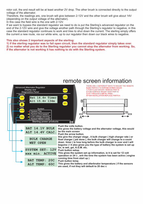
remote screen information
A
B
THERE ARE 3 DIFFERENT WAYS TO MOUNT THE REMOTESLIDE PARTS A TO EXPOSE SCREW HOLES1) FOR FLUSH MOUNT, REMOVE PART B2) FOR SURFACE MOUNT KEEP PART B3) FIT THROUGH A METAL PANELAFTER INSTALLATION REPLACE PARTS A
Push the volts button.this gives the battery voltage and the alternator voltage, this would be the main screenPush the arrow button.this give the charger stage , it bulk charger ( high charger rate ) or float charger ( job done ), the bulk charger will change to a count down timer ( ie how long before the bulk charger is over and t will beguine ) l it also gives you the type of battery the system is set up for, ie wet, gel, A.G.M. etc.Push button setup.This gives the system set up information, ie it is set for 12 volt operation or 24 v , anh the time the system has been active ( engine running time from start up )Push button temp.This gives the battery and alterbnator temperature ( if the sensors are used, if not they will default to 20 dec c

Basic generatic alternator control system Diagram 1It is vital to understand in order to see what is going on and to help in fault finding.Diagram 1 shows the basic circuit for alternators. The rotor ( as shown above ) rotates inside a stator ( the solid bit of the alternator that you can see ) the rotor creates a magnetic field which is then converted into electric by the stator and sent to the batteries via the main positive output cable. In order to control the output voltage we must control the amount of magnetic flux being created by the rotor inside the alternator. The example in diagram 1, simply has 14V on one side and 0V on the other, this would result in the rotor creating its maximum amount of magnetic flux, and therefore charging the batteries at the max rate and will eventually destroy the batteries by over charging them.
carbonbrushes
copper slip ringson rotor
0 voltsneg
14 volts
alternator rotor
Diagram 1
alternator stator
B+ main positive
output
B -alternator case
In order to control this process then we must introduce a regulator which looks at the battery voltage and controls the rotors voltage in order to reduce or increase the alternator’s performance. The regulator looks at the alternator’s output voltage and controls the rotor field current to increase or decrease the current of the alternator to maintain a constant output voltage. Now, this is where things get a little bit difficult. With regards to controlling the rotor current (and as such the alternator output voltage) it does not matter if you control the voltage on the way into the rotor (point A) or on the way out of the rotor at (point B). From the alternator’s point of view it does not matter which side the rotor is controlled, either side is equally effective,
If the regulator was in position A then it is on the positive side of the rotor and is controlling the positive going into the rotor, it is hence called a positive field control alternator. If the regulator was fitted into position B then it would be controlling the voltage coming out of the rotor on the negative side, down to negative, this would be referred to as a negative field control alternator.As explained in the fitting instructions, most European and Japanese alternators are negative field control.
Basic alternator control: Diagram 2
however, it matters a lot to you when fault finding.
0 voltsneg
14 volts
Diagram 2
B+ main positive output
B -alternator case
AB
Understanding alternator field control to assist in fitting
to alternator which has no regulator
Page 11
carbonbrushes
0 voltsneg
14 volts
Diagram 3
B+ main positive output
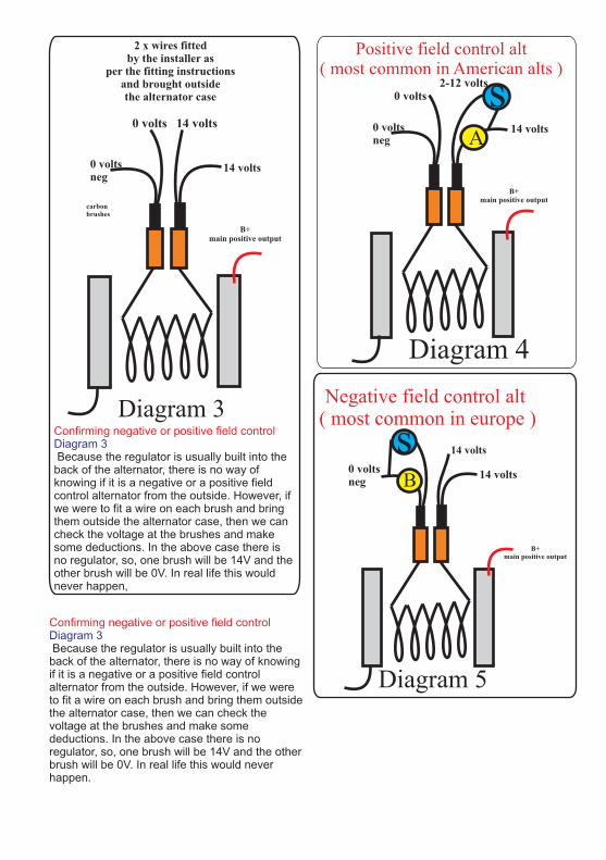
2 x wires fittedby the installer as
per the fitting instructionsand brought outsidethe alternator case
14 volts0 volts
Confirming negative or positive field control Diagram 3 Because the regulator is usually built into the back of the alternator, there is no way of knowing if it is a negative or a positive field control alternator from the outside. However, if we were to fit a wire on each brush and bring them outside the alternator case, then we can check the voltage at the brushes and make some deductions. In the above case there is no regulator, so, one brush will be 14V and the other brush will be 0V. In real life this would never happen,
Diagram 4
B+ main positive output
0 voltsneg
14 volts
2-12 volts 0 volts
Positive field control alt ( most common in American alts )
A
s
0 voltsneg
14 volts
Diagram 5
B+ main positive output
14 volts
B
sNegative field control alt
( most common in europe )
Confirming negative or positive field control Diagram 3 Because the regulator is usually built into the back of the alternator, there is no way of knowing if it is a negative or a positive field control alternator from the outside. However, if we were to fit a wire on each brush and bring them outside the alternator case, then we can check the voltage at the brushes and make some deductions. In the above case there is no regulator, so, one brush will be 14V and the other brush will be 0V. In real life this would never happen.

Your 100 % satisfaction is our goal.
Product Warranty:
We realise Please do not throw out any shipping or that every customer and circumstance is unique. packaging materials.If you have a problem, question, or comment All returns for any reason will require a proof of please do not hesitate to contact us. We welcome purchase with the purchase date. The proof of you to contact us even after the warranty and purchase must be sent with the returned return time has passed. shipment. If you have no proof of purchase call
the vendor who supplied you and acquire the Each product manufactured by Sterling Power appropriate documentation. comes with at least a 2 year limited factory warranty. Certain Products have a warranty To make a claim under warranty, check phone period of time greater than 2 years. Each product number on internet . We will make the best effort is guaranteed against defects in material or to repair or replace the product, if found to be workmanship from the date of purchase. At our defective within the terms of the warranty. Sterling discretion, we will repair or replace free of charge Power will ship the repaired or warranty any defects in material or workmanship that fall replacement product back to the purchaser, if within the warranty period of the Sterling Power purchased from us.product. The following conditions do apply: - The original receipt or proof of purchase Please review the documentation included with must be submitted to claim warranty. If proof your purchase. Our warranty only covers orders cannot be located a warranty is calculated purchased from Sterling Power. We cannot accept from the date of manufacture. warranty claims from any other Sterling Power - Our warranty covers manufacture and distributor. Purchase or other acceptance of the material defects. Damages caused by abuse, product shall be on the condition and agreement neglect, accident, alterations and improper that Sterling Power USA LLC and Sterling Power use are not covered under our warranty. LTD shall not be liable for incidental or - Warranty is null and void if damage occurs consequential damages of any kind. Some states due to negligent repairs. may not allow the exclusion or limitation of - Customer is responsible for inbound consequential damages, so, the above limitations shipping costs of the product to Sterling may not apply to you. Additionally, Sterling Power Power either in the USA or England. USA and Sterling Power LTD neither assumes nor - Sterling Power will ship the repaired or authorizes any person for any obligation or liability warranty replacement product back to the in connection with the sale of this product. This purchaser at their cost. warranty is made in lieu of all other obligations or
liabilities. This warranty provides you specific legal If your order was damaged in transit or arrives rights and you may also have other rights, which with an error, please contact us ASAP so we may vary from state to state. This warranty is in lieu of take care of the matter promptly and at no all other, expressed or implied. expense to you. This only applies for shipping which was undertaken by our company and does not apply for shipping organised by yourself.
Customer Service & Warranty
Sterling Power Products Ltd
ENGLAND www.sterling-power.com
Sterling Power USA www.sterling-power-usa.com
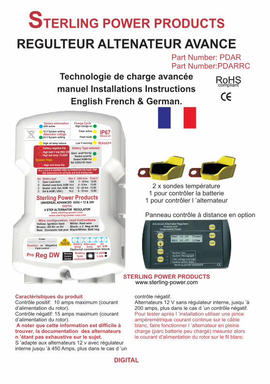
Part Number: PDARPart Number:PDARRC
2 x sondes température1 pour contrôler la batterie
1 pour contrôler l ’alternateur
Panneau contrôle à distance en option
RoHScompliant
STERLING POWER PRODUCTS
DIGITAL
REGULTEUR ALTENATEUR AVANCE
Technologie de charge avancée
manuel
English French & German.
Installations Instructions
STERLING POWER PRODUCTSwww.sterling-power.com
Caractéristiques du produit
Pour tester après l ’installation utiliser une pince ampèremètrique courant continue sur le câble
A noter que cette information est difficile à blanc, faire fonctionner l ’alternateur en pleine trouver, la documentation des alternateurs charge (parc batterie peu chargé) mesurez alors n ’étant pas exhaustive sur le sujet. le courant d’alimentation du rotor sur le fil blanc.
contrôle négatif.Contrôle positif: 10 amps maximum (courant Alternateurs 12 V sans régulateur interne, jusqu ’à d’alimentation du rotor). 200 amps, plus dans le cas d ’un contrôle négatif. Contrôle négatif: 15 amps maximum
S ’adapte aux alternateurs 12 v avec régulateur interne jusqu ’à 450 Amps, plus dans le cas d ’un
(courant d’alimentation du rotor).

NSTRUCTIONS DE MONTAGE POUR LES REGULATEURS.
Ce nouveau produit peut convenir pour des installations en 12 ou 24 volt. Il serait catastrophique d ’installer l ’appareil réglé en 24 Volts sur une installation en 12 V. Toutes les précautions sont prises pour que cette erreur ne se produise pas. Le réglage d ’origine est en 12 Volts, pour régler en 24 Volts il faut établir une liaison électrique, le cavalier assurant cette liaison n ’est pas placé dans la boîte, il est fixé à l ’aide d ’un adhésif au milieu de ce livret. Pour une installation en 24 volts il faut placer cette pièce.
installation standard
Merci d’avoir fait l’acquisition d’un des régulateurs d’alternateurs les plus avancés du marché. Attention à ne pas sous-estimer l’effet que cet appareil aura sur un système de charge en place. Il est important de prendre en compte que les câbles existants et Démontez l'alternateur. Repérez les balais, les composants en place (répartiteur par exemple) connectez un câble de 2.5 mm2 de 200 mm de pourraient ne pas être en mesure de supporter long, à chaque balais (vissé ou soudé suivant l’amélioration des performances de l’alternateur, l'alternateur). Réinstallez l'alternateur, mesurez la vous devez vous assurer que les câbles existants tension entre chacun des fils et la terre, (assurez-de l’alternateur seront en mesure de supporter la vous qu'il y a une tension d'au moins 14 V en sortie puissance nominale de l’alternateur et qu’ils sont d'alternateur, ce qui confirme qu'il fonctionne). Si correctement dimensionnés par rapport à leur vous obtenez le résultat suivant: 0V sur un fil, et 2-longueur, attention aussi aux ampèremètres sans 12V vous avez un alternateur à contrôle positif, shunt qui induisent de la longueur de câble conservez le fil dont la tension est 2-12V sécurisez supplémentaire. A noter que le régulateur le fil dont la tension est nulle, et éloignez le. Si vous d’alternateur évolué intègre de nombreuses obtenez une tension d'environ 14V sur un fil et 2-fonctions de sécurité qui permettent de protéger 12V sur l'autre, vous avez un alternateur à contrôle votre installation si elle se révélait sous négatif, conservez le câble dont la tension est 2-dimensionnée pour supporter l’amélioration de 12V, sécurisez et éloignez l'autre câble. Connectez performances amenée par cet appareil. Il les autres câbles en respectant le schéma de diagnostiquera la majorité des problèmes câblage. A ce stade ne pas connecter le câble blanc rencontrés et cessera son effet. (câble de contrôle du rotor). Quand tous les autres
câbles sont connectés, choisissez le montage Les régulateurs d’alternateur évolués sont conçus associé à votre type d'alternateur et le type de pour augmenter la tension de sortie de l’alternateur, batterie (voir les instructions). Une fois l'appareil sur les installations anciennes et dans la majorité correctement programmé, connectez le dernier des cas, cela ne pose pas de problème, par contre câble blanc au câble de contrôle du rotor.lorsque le moteur est équipé d’un système ECU : (concerne les installateurs (système de gestion électronique) la mise en place moins expérimentés) du régulateur d’alternateur peut provoquer des PRE INSTALLATION:alarmes générées par le système de gestion Dans la majorité des cas, cet appareil ne pose pas électronique en place sur le moteur. Pour les de problème de mise en place si une démarche moteurs dotés d’un tel système, il est préférable de logique est adoptée. mettre un chargeur d’alternateur ou un chargeur Pour l’installation, il est nécessaire de disposer d’ un de batterie à batterie. Ces deux appareils voltmètre ainsi que d’un fer à souder.permettent d’obtenir le même résultat mais sans Ce nouveau régulateur d’alternateur a été conçu avoir à intervenir sur l’alternateur, et ne posent pour s’adapter à tout type de batterie et donc pas de problème de compatibilité avec le d’alternateur. Dans un premier temps, il est donc système de gestion ECU. important d’identifier les principales caractéristiques
de votre installation. Cela vous permettra de paramétrer correctement votre régulateur et d’en tirer le meilleur parti.Merci de collecter les informations ci-dessous sur votre installation et de remplir les espaces vides.
Si cela est possible il est intéressant de tester le courant maximum contrôlant le champ magnétique, après l ’installation. Placez une pince ampèremètrique sur le câble blanc. Faites fonctionner l ’alternateur à pleine puissance( faites tourner le moteur assez vite et déchargez les batteries de sorte que l ’alternateur fonctionne à pleine puissance). Mesurez alors l ’intensité du courant de champ sur le fil blanc. Si les capacités de l ’appareil sont dépassées il va chauffer et se couper, il ne sera pas endommagé.
Instructions condensées (réservées aux installateurs informés et expérimentés).
Caractéristiques du produit
En réalité: règle approximative (information difficile à obtenir)
contrôle négatif.Alternateurs 12V sans régulateur interne: 200A pour un contrôle positif, plus pour un contrôle négatif.l
Alternateur contrôle positif: intensité maximum du courant d’alimentation du rotor: 10A Contrôle négatif: 15A maximum.
S ’adapte aux alternateur 12 V avec régulateur jusqu ’à 450A, plus encore dans le cas d ’un

pouvez avoir besoin de souder des petits câbles.
4)Connaissances de base de gestion du système électrique sur les moteurs. Si l'installation est pourvue d'un système électronique de contrôle (ECU) le régulateur
Type d’Alternateur : Il y a deux types ne convient pas, vous devriez utiliser un d ’alternateurs, négatif ou positif. Si vous ne chargeur d'alternateur Sterling ou un chargeur connaissez pas cette information, la façon de batterie à batterie Sterling, ces appareils ne déterminer le type d’alternateur est expliquée modifient pas le système électrique primaire du dans la suite de ce document. moteur.
5)Si l'alternateur est sous garantie, si le moteur est neuf, nous vous recommandons de vous orienter vers le chargeur de batterie à batterie,
Type de batteries: Il y a trois principaux types qui ne nécessite pas d’intervention sur le de batteries: Le cycle de ces trois types de système électrique moteur, et n'affecte pas la batteries est clairement spécifié sur le garantie. Si le bateau a plus de 4 ans ces régulateur évolué. Pour un même type de conseils ne s'appliquent pas.batteries le cycle de charge peut être différent Si vous ne dominez pas les connaissances en fonction du constructeur. La meilleure précédentes, il est préférable de faire appel à solution est de mettre en place le cycle de un professionnel. Vous pouvez aussi installer charge recommandé par le fabricant de vos un chargeur d'alternateur Sterling ou un batteries. chargeur de batterie à batterie Sterling, plus
onéreux, mais beaucoup plus simple à 1) Batterie au plomb acide ouvert, sur ce installer. type de batteries, il
3) batteries Gel ( spécifications Exide ) nécessite le maintien d’une tension de 14.4 volts pendant une durée de 10 à 12 heures.4) Batteries Gel USA 14,1V maxiLe nouveau logiciel du régulateur digital calcule automatiquement la capacité du parc batteries, l’état de charge ainsi que la puissance de l’alternateur et utilise ensuite le processeur intégré pour calculer le cycle de charge adapté à chaque démarrage du moteur. Il s'agit de la seule partie difficile, elle permet de déterminer le type d'alternateur, cette tâche accomplie remplissez la case ci-dessus. Il y a beaucoup d'alternateurs différents, les instructions suivantes s'appliquent à tous les alternateurs.La partie importante est d'identifier le câble de contrôle du rotor. Ce câble commande toutes les opérations de l ’alternateur. Pour entreprendre cette installation, vous devez posséder des connaissances de base dans les domaines suivants:1)Utilisation d'outils classiques pour démonter l'alternateur du moteur.2)Connaissances de base en courant continu sur les véhicules, les bateaux ..3)Petites connaissances en soudure, vous
Tension alternateur (12 ou 24 volt).....................VOLTS Courant de l’alternateur (35amp, 55amp etc)....................AMPS
Pour 24 volts, multipliez les tensions par 2.
Type d’alternateur: (Neg or Pos).........................
Sélection type batterie voir fig 1.
est possible d’ajouter de l’eau. Ces batteries autorisent un rythme de charge rapide. 14.8 volts max pour une durée d’absorption pouvant aller jusqu’à 8 hrs2) Batteries au plomb fermé et batteries AGM, 14.4 volts max 4-6 hrs
Installation du fil contrôle de l ’alternateur:

1
2
3
4
10
8
11
9
512
13
Fig 1
67
14
( Pour 24 v x toutes les Alarmes et indications des tensions par 2 )
leds
1) Bleue
2) Jaune:
3) Verte:
4) Jaune:
5) Rouge:
6) Rouge
( Pour 24 v x toutes les
Montre que l ’appareil est alimenté, si cette led est éteinte, vérifiez la tension sur le fil jaune, pour vous assurer que l ’appareil est alimenté, elle doit s ’éteindre quand le moteur est arrêté.
supérieure à 15,5V), il y a trois causes principales
pouvant conduire à ce problème1) Le régulateur de l’alternateur est défectueux, si la tension continue à augmenter après que la led se soit allumée, c’est en général le régulateur d’origine qui est en cause.
Indique que l ’appareil est réglé pour un
alternateur fournissant une tension de 12 V.Indique que l ’appareil est réglé pour un
alternateur fournissant une tension de 24 V.Coupure à cause d ’une température trop
haute de l ’alternateur: La sonde a détecté une température supérieure à 90 degrés, le régulateur d ’alternateur s ’est déconnecté, il se connectera de 2) Le régulateur évolué Sterling est en panne. Si nouveau à 65 degrés, ce processus est automatique la tension batterie redescend à 14 volts une fois et ne demande pas d ’intervention. Si cette que la led s’est allumée, le régulateur Sterling procédure se produit trop souvent, vérifiez la est en panne et il doit être retourné pour température de votre compartiment moteur, placer maintenance ou remplacement aussi vite que un ventilateur amenant de l ’air frais sur l ’arrière de possible. Il est quand même possible d’utiliser le l ’alternateur, la circulation d ’air se fait de l ’arrière moteur pour les cas d’urgence puisque le vers l ’avant de l ’alternateur. régulateur chargera les batteries jusque 15,5V
Problème sur les bornes négatives de la et arrêtera ensuite son effet. Le moteur doit batterie, il y a un problème entre la borne négative néanmoins être utilisé uniquement pour les cas de la batterie et la borne négative de l ’alternateur. d’urgence (uniquement pour le retour au port!).La cause est souvent une mauvaise connexion, 3)D ’autres systèmes de charge sont nettoyez toutes les connexions et vérifiez les défectueux, chargeur de batterie, éolienne, sertissages. panneaux solaires, dans ce cas la tension
deux indications possibles: continue de monter même lorsque le moteur est Cas 1: Si la led est allumée en permanence, ceci coupé.
indique une tension batterie importante (tension Cas 2: La led clignote.
ARRÊTEZ le moteur aussi vite que possible et déconnectez les câbles de l’alternateur. Vous pouvez ensuite continuer votre voyage et réparer le problème le plus vite possible. Sterling ne peut pas résoudre ce problème dans la mesure où c’est votre système d’origine qui est défectueux. Si vous ne réagissez pas à ce problème vous allez faire détériorer vos batteries.

FUSE
POS NEG
Alternator field typeselector under lid
29
RemoteControlSocket
Positive or NegativeField control
Fuse
65 74 8
3 92 01
14
15 1716 18
1922
23
2120
26
27 2524
28
Fig 2
tensions par 2 )
7) Rouge 8) Verte
9) Jaune
10) Verte Elements sous le couvercle de
protection.14) Câble Jaune :
11) Jaune
12) Verte
13) Jaune 14)
15 & 16 ) Fuse :
17 & 19 )2 câbles noirs:
Ceci indique que le capteurde C’est le problème le température a mesuré une température supérieure à plus courant, ceci indique que la tension de 50 degrés. Ceci indique en général que la batterie l’alternateur a dépassé 17,5V. Cela arrive pour est défectueuse. Si la tension est sous 14V et la différentes raisons:température supérieure à 50° , la batterie est 1) Le câble reliant l’alternateur aux batteries est défectueuse et il faut la remplacer aussi vite que trop fin ou/et trop long et induit des chutes de tension possible. trop importantes.
Haute température. 2) Si le circuit comprend un ampèremètre, cela Charge haute, l ’alternateur charge a son signale fréquemment un problème de connexion de
maximum. Doit rester allumée jusqu ’à ce que la LED cet ampèremètre.3 soit active signifiant que le cycle de charge haute 3) Si l’installation a déjà fonctionné correctement est terminé. pendant plusieurs semaines, vérifiez que le
Le minuteur est activé: cela se produit répartiteur de charge (relais, répartiteur à diode...) quand la tension atteint 13.9 - 14 volts dépend aussi fonctionne correctement et vérifier l’état des du temps nécessaire pour arriver à cette tension. Le connexions. Lorsque cette alarme survient le logiciel détermine la durée de la charge haute, cela régulateur d’alternateur se trouve isolé de peut varier de 1 à 6 heures, cette durée s ’affiche sur l’alternateur et n’a plus d’effet.le panneau de contrôle, le temps restant en charge d’absorption est aussi affiché. Cette LED est active tant que la charge reste haute.
Floating: Ceci indique que le cycle de charge haute est terminé et le passage au cycle d’entretien. Le système fournit une charge d ’entretien aux environ de 14V.
Alarme de tension basse: Ceci indique une tension basse sur les batteries de service et est en général causé par un alternateur défectueux.
Indique le type de batteries en association avec 13
Sonde Temperature, 2 sondes une pour la batterie l ’autre pour l ’alternateur,
Sélection du type d’alternateur, l ’appareil fonctionne sans les sondes, la peut être réglé sur contrôle à champ positif ou température est fixée à 20 degrés par défaut,négatif, vérifiez que la sélection est correcte avant on perd alors les fonctions associées auxd’activer le produit. sondes.
Indique le type de batteries associé à 12
Toutes les leds clignotent:
Si la tension continue à augmenter, il faut vérifier le fonctionnement du régulateur d’origine de l’alternateur et déconnecter l’alternateur pour ne pas surcharger les batteries.
Il s’agit du câble d’alimentation du régulateur. Il doit être connecté au D+ de l’alternateur ou n’importe quelle borne qui est alimentée lorsque le moteur est en marche. Si il n’y a pas d’interrupteur de contact un simple bouton poussoir on/off peut convenir, quand le moteur fonctionne mettre l’appareil en circuit, quand le moteur s’arrête déconnecter l’appareil. Vous pouvez rallonger ce câble autant que vous voulez.
Il y a deux câbles noirs, ces câbles doivent être connectés à la borne B-
(négative de l’alternateur) ou à la carcasse de l’alternateur. Si ces câbles sont ralongés, ils doivent être rallongés en deux câbles séparés, cela peut paraître ridicule mais c’est nécessaire! Ne pas rallonger ces câbles dans la mesure du possible.
Ce câble permet de contrôler l’alternateur, et doit être connecté sur le câble que vous venez de mettre en place sur le balai de l’alternateur. Ce câble peut être connecté ou déconnecté lorsque l’alternateur fonctionne, ceci peut être utile dans certains cas où le régulateur évolué a besoin d’être éteint (i.e. petit moteur dans les manoeuvres ou dans le courant). Il a été noté que le régulateur peut faire perdre jusqu’à 1,5 noeuds sur des petits bateaux avec des moteurs de 10/15ch. Néanmoins la plupart des personnes connectent ou déconnectent ce câble par curiosité pour voir l’effet du régulateur d’alternateur (avec le modèle Pro Digital, ceci peut être effectué grâce au panneau de contrôle optionnel). Ne pas rallonger ce câble dans la mesure du possible.
: Ce câble est utilisé comme sonde de tension batterie, il est important de noter que ce câble et l’alternateur ne doivent pas se trouver isolés des batteries lorsque le moteur est en marche.La position de ce câble dépend de votre installation: Répartiteur de charge à diode: Si votre alternateur est connecté à un répartiteur à diode, positionner ce câble du côté batterie du répartiteur. Il faut le placer au niveau du plus gros parc de batteries (si vous disposez de deux parcs de batteries identiques, placez le sur le parc de batteries le plus sollicité).Relais séparateur: Même principe que ci dessus. Néammoins notez que la plupart des relais bon marché sont sous dimensionnés et ne peuvent être utilisés que pour des faibles puissances. Ne soyez pas surpris si ce relais tombe en panne après la mise en place du chargeur d’alternateur. Vérifiez les capacités de relais à limiteur de tension, et assurez vous que la tension maximum admise est supérieure à la tension fournie par l ’alternateur, si vous utilisez un relais pour une ancre, un winch ou un convertisseur important, nous vous conseillons de regarder les relais limiteur de courant Sterling.Sterling 0.0 Pro Split R. De loin le meilleur système de répartition de charge, il dispose en effet de nombreuses fonctionnalités supplémentaires en comparaison des répartiteurs classiques. Si ce produit est utilisé, il faut connecter le câble rouge du régulateur Sterling à la borne notée “sense terminal” du répartiteur de charge. Contacteur trois positions: Beaucoup de bateaux disposent d’un tel contacteur qui permet de sélectionner bat1, bat2 ou les deux batteries (both). Avec ce type de répartiteur, connectez le câble de sonde de tension à l’arrière de l’interrupteur sur la borne commune. Avec ce type de système , vous choisissez la batterie à recharger (batterie 1, batterie 2 ou les deux). Etant donné qu’il faut
18) Câble blanc:
23) Modification 12-24 Volts,
Attention ne pas installer l’appareil modifié sur un alternateur 12 volts, vous endommageriez votre système électrique et vos batteries. 24) Bouton tournant de sélection type de batterie
20) Bloc connexion sonde température.
21) Sonde température alternateur. 22) D+ désengagement.
sur le régulateur de l’alternateur, ils allument la lampe témoin pour remonter le problème. Cette fonctionnalité n’est pas compatible avec le régulateur d’alternateur dans la mesure où celui-ci conduit à l’augmentation de la tension aux bornes de l’alternateur et par conséquent laisse penser à l’alternateur que son régulateur est en panne. Le régulateur d’alternateur dispose d’un relais qui désengage la lampe de charge (connecté au D+) après s’être assuré que tout était correct, même si l’alternateur envoie une alarme celle-ci est stoppée par le régulateur Sterling. En cas de problème quelconque, le régulateur Sterling remonte l’alarme.
.
Cette sonde est du même type que la sonde utilisée sur l’alternateur, il vaut mieux la placer sur une des batteries du parc domestique, le parc de batteries qui a la durée de vie la plus courte. Il s’agit de contrôler la température des batteries. La tension de charge est réduite si la température des batteries s’élève à cause de la température de l’air ambiant ou d’une batterie défectueuse . Si la température des batteries dépasse 50 degrés, une alarme est transmise au panneau de contôle (si il est utilisé) et la LED 5 clignote.
La plupart des alternateurs disposent d’une lampe témoin sur le tableau du moteur (cette lampe est allumée lorsque le moteur démarre et s’arrête dès que l’alternateur commence à produire du courant). Si l’alternateur tombe en panne, dans la majorité des cas, la lampe témoin de charge s’allumera. Certains alternateurs modernes disposent d’une fonctionnalité plus avancée (Les alternateurs butec et certains nouveaux alternateurs merellie, moins de 0,1% des alternateurs utilisés), en cas de problème
C’est une erreur fatale et celle ci ne peut être annulée que si le moteur est redémarré. En tout cas, il est nécessaire de comprendre ce qui a causé cette alarme, il ne faut pas se contenter de réinitialiser le système dans la mesure où ce problème peut conduire à un dégagement gazeux de la batterie et donc à un incendie. Si vous ne souhaitez pas utiliser le capteur de température ou si celui ci est défectueux, le logiciel du régulateur d’alternateur le détectera et considèrera la température comme constante et égale à 20 degrés.
25)Prise écran de contrôle 26) Rouge
Si vous ne souhaitez pas utiliser cette sonde ou si elle est détériorée, le logiciel détecte l’erreur et se fixe à une température de 20 degrés.
En reliant les deux bornes, cet appareil devient adapté à un alternateur 24 volts.
Permet de sélectionner les paramètres de votre batterie.
systématiquement penser à bouger l’interrupteur Volvo). Nénmmoins les choses peuvent se révéler pour recharger les deux batteries, il est intéressant plus complexes:de passer à un système plus évolué avec a) Alternateur brushless, le plus commun est le répartition automatique. S.E.V. Marshell 35 amp mis en place sur les Pour les bateaux qui disposent d’une batterie anciens moteurs Volvo/Buch. Sur le régulateur de éloignée dédiée au propulseur d’étrave, il est l’alternateur, il y a une connexion F ou D/F, il s’agit recommandé de mettre en place la sonde de du câble de contrôle de l’électro aimant où doit être tension sur le parc de batterie principal afin que ce raccordé le câble blanc du régulateur. Cet parc de batterie ne subisse pas une tension de alternateur est un alternateur à contrôle positif; il charge trop importante due à la chute de tension du est donc nécessaire de modifier la configuration du câble permettant de recharger la batterie du régulateur d’alternateur évolué de négatif à positif. propulseur d’étrave. (CONNECTER LE CABLE MARRON A LA BORNE La batterie du propulseur d ’étrave bénéficiera D+/61 /L , LE AUTRES CABLES SE néanmoins de la charge du régulateur d ’alternateur CONNECTENT DE FACON CLASSIQUE). Le
, Cet appareil meilleur conseil que l’on puisse vous donner est comprend une connexion spécifique pour ce câble. d’utiliser cet alternateur en secours et de le
Se connecte à la borne remplacer par un alternateur de puissance négative du parc de batteries domestiques. Permet raisonnable, un alternateur de 35 amp ne permet de comparer la tension du parc de batteries à la pas de charger de façon efficace les batteries).tension à la borne négative de l’alternateur. Si la chute de tension est supérieure à 1,5 Volts une alarme est déclenchée et le chargeur d’alternateur est désactivé. Peut être rallongé sans problème.
Le câble marron doit être connecté au D+ de l’alternateur, il s’agit d’un petit câble situé à l’arrière de l’alternateur qui est habituellement indiqué comme “D+” ou “ING” ou “ L” ou “61”, ce câble est utilisé pour alimenter la lampe témoin de charge sur le tableau moteur. Connecter le câble marron sur la même borne que le D+ tout en laissant ce câble en place
Ne pas rallonger ce câble dans la mesure du possible b) Régulateur externe: certains alternateurs ont
un régulateur externe qui est connecté à l’alternateur grâce à 3 ou 5 câbles de petite section (habituellement sur des alternateurs anciens ), conseil: ces câbles sont connectés aux balais de l’alternateur (ceux qui permettent de contrôler la
1) Isoler l’alternateur des batteries pour éviter tout puissance de l’alternateur), identifier les balais en risque de court circuit. Il est recommandé d’avoir un suivant la procédure standard décrite ci-dessous. ami à proximité pour une aide éventuelle. Remplacer le régulateur une fois que les câbles 2) Enlever tous les câbles de l’arrière de existants sont raccordés au régulateur Sterling. Ce l’alternateur (noter la position des câbles existants régulateur Sterling peut être utilisé avec des pour faciliter le remontage). alternateurs d’une puissance allant jusqu’à 200A 3) Une fois les câbles retirés et isolés pour éviter seul ou jusque 300A avec le régulateur existant. tout risque de court circuit sur le bloc moteur, retirer c) Les alternateurs Hitachi et Yanmar l’alternateur. nécessitent une découpe pour accéder aux balais, 4) Pas trop compliqué? Nous allons maintenant ceci permettra d’accéder aux balais situés à commencer la partie difficile! Nous allons accéder l’arrière de l’alternateur. Vous pouvez noter deux aux balais (ou charbons) de l’alternateur qui petits trous dans le boîtier contenant les balais qui fournissent le courant à l’électro aimant (rotor); ils permettent de faire ressortir les câbles connectés sont en général connectés au régulateur existant aux balais lors du réassemblage.de l’alternateur. Les charbons sont des pièces 5) Après avoir trouvé les balais, souder un câble de d’usure, il y a donc forcément possibilité d’y 10 A ( ou 2,5mm2) sur le dessus de chacun des accéder pour les remplacer. Démonter le régulateur balais.de l’alternateur (c’est un composant en général à Problème: Les bornes de connexion des l’arrière de l’alternateur fixé par trois ou quatre vis). alternateurs Lucas sont en acier inoxydable, et par Une fois les vis enlevées l’alternateur peut être conséquent l’étain habituellement utilisé pour la extrait avec les balais. Ceci ne pose pas de soudure ne peut être utilisé dans ce cas. Utilisez de problème sur 80% des alternateurs (Lucas, Bosch, l’étain classique (celui utilisé par les plombiers) et
Répartiteur Sterling Pro Split R
28) Câble marron
29) Sondes températures x 2
Procédure d ’installation
27) Câble noir à rayures
Un ancien régulateur mécanique Bosch (25 ans) nécessite aussi des instructions particulières, il ne doit pas être utilisé en même temps que le régulateur d’alternateur Sterling. Néanmoins si vous faites les tests comme spécifié ci-dessous, vous en déduirez que c’est un alternateur à contrôle positif. Quand le câble de contrôle de l’électro aimant est identifié, configurer le régulateur d’alternateur Sterling sur Positif et retirer l’ancien régulateur Bosh (cette situation n’est pas courante). Vous pouvez consulter la suite de cette notice pour
Certains comprendre le fonctionnement d’un alternateur, alternateurs récents ne disposent pas de D+, dans cette explication est suffisante pour comprendre ce cas connecter ce câble au B+ (sortie puissance comment procéder lorsque vous avez un + de l’alternateur). alternateur sans régulateur intégré.
, utilisées pour contrôler les températures des batteries et de l’alternateur.

ceci résoudra le problème. Delco.6) Après avoir soudé un câble à chacun des balais, Dans chacun des cas, nous allons conserver le remonter l’alternateur et le replacer sur le moteur. câble ayant une tension comprise entre 1 et 11 Problème: Les alternateurs Valéo mis en place sur volts et supprimer celui qui a une tension de 0 ou 14 les moteurs Volvo nécessitent une découpe du volts. (assurez-vous que ce câble ne pourra pas plastique de protection pour le passage des toucher l’alternateur).nouveaux câbles. Utilisez votre bon sens et ne 10) Après avoir identifié le câble de contrôle de coincez jamais un câble entre le boîtier de l’alternateur, la partie compliquée est terminée et l’alternateur et la protection plastique. nous allons maintenant procéder au montage du 7) Assurez vous que l’extrémité de chacun des régulateur d’alternateur. nouveaux câbles ne se touchent pas et reconnectez Assurez vous de bien avoir refixé le régulateur l’alternateur. existant (il ne doit pas être laissé à l’extérieur).8) Après avoir rebranché l’alternateur, démarrez le moteur et 1) A ce stade, vous avez dû passer la phase de
i.e. la lampe témoin pré-installation, nous allons maintenant de charge de l’alternateur doit être éteinte et paramétrer le régulateur.l’alternateur doit recharger les batteries. 2) Retirer le couvercle inférieur en dévissant l’écrou.
Vous devez voir une configuration analogue à la figure 2, un fusible a 2 positions , figure 2, numéro 15 et 16 et un bouton de sélection du type de batterie le 24.Sélection du type de batterie:Tourner le bouton 24 pour aboutir au type de votre batterie, voir la table fig3, la sélection sera confirmée par des LEDs
Vous devez avoir établi le type de votre alternateur (contrôle positif ou
9) C’est la partie la plus importante. Avec le négatif). Pour paramétrer le type d’alternateur, moteur en marche, en utilisant un voltmètre reportez-vous à la figure 2 pour un alternateur nous allons mesurer la tension (par rapport à la négatif le fusible doit être proche de la paroi masse) sur chacun des câbles que vous venez intérieure du boîtier, pour un alternateur négatif de souder: le fusible occupe l ’autre position.Cable 1 = ..............volts cable 2 =...............volts Le régulateur possède un fusible standard de Prenez aussi note de la tension de l’alternateur 10 A, ce fusible est maintenu par 3 pattes. Le lorsque vous faites cette mesure, si l’alternateur fusible est mis en place par défaut pour un fonctionne correctement, nous devons avoir une alternateur négatif. Si vous disposez d ’un tension de 13-14 volts. Si la tension est sous 13V, alternateur positif retirez le fusible et placez le l’alternateur ne fonctionne pas, si cette tension est dans l ’autre position. Les positions au dessus de 14,5V, alors le régulateur existant de correspondantes aux type d ’alternateur sont l’alternateur est défectueux ou l’un des câbles que clairement marquées sur l ’étiquette collée sur vous venez de connecter est en court-circuit avec la le couvercle Fig 3masse.
Détermination du type d’alternateur:Si la tension de l’un des deux câbles est comprise entre 2-12 volts et que l’autre est à 14 volts il s’agit le logiciel intégré dans le nouveau régulateur d’un alternateur à contrôle négatif, aller au chapitre évolué Digital calcule automatiquement le temps précédent (pré installation) et écrire du cycle d’absorption à chaque fois que le moteur Si la tension de l’un des deux câbles est comprise est démarré. Celui-ci durera de 1 à 12 heures en entre 1-11 volts et que l’autre est à 0 (zéro) volt, il fonction du temps mis pour atteindre la tension de s’agit d’un alternateur à contrôle positif, aller au 14 volts; cette durée sera différente à chaque fois chapitre précédent (pré installation) et écrire que le moteur est démarré et dépendra aussi du
type de batteries paramétré. Le logiciel interne (Pour information, 90% des alternateurs en Europe prend en charge cette fonction.
sont négatifs, cela inclut les alternateurs Bosch, Valeo (Volvo), Hitachi (Yanmar), Lucas. Les seuls Démarrer le moteur, la led vert indiquant la phase alternateurs à contrôle positif sont les alternateurs de boost et la led de floating (jaune ou verte en
anciens avec des régulateurs externes ou des fonction du type de batterie) doivent être allumées, alternateurs américains tels que Motorola et AC la led verte clignotera pendant deux minutes
assurez-vous que l’alternateur fonctionne correctement,
ATTENTION: NE PAS ALLER PLUS LOIN SI L’ALTERNATEUR NE FONCTIONNE PAS CORRECTEMENT. L’alternateur doit fonctionner normalement avant de continuer. Ildoit délivrer une tension autour de 14V qui assure la recharge des batteries.
ATTENTION: NE PAS ALLER PLUS LOIN SI ATTENTION: Assurez-vous d ’avoir choisi le L’ALTERNATEUR NE FONCTIONNE PAS bon type de batteries, vérifier la tension, un CORRECTEMENT. L’alternateur doit mauvais réglage peut endommager vos fonctionner normalement avant de continuer. Il batteries.doit délivrer une tension autour de 14V qui assure la recharge des batteries.
Si ce paramétrage est mal effectué, ceci peut détériorer le régulateur évolué et le régulateur existant de l’alternateur.
NEG
POS
Type d ’alternateur:
Calcul du cycle d ’absorption:
Test du système:
Paramétrage du régulateur avant installation
Nous allons le répéter pour les personnes qui pensent que c’est une blague!

j
h So
nd
e te
mp
era
turef l
a = Jaune vers allumage (or D+/L/61)b = blanc vers le champ alternateurc = marron vers alternateur ou D+/62/L/DLd = 2 x noirs vers alternateur neg.e = répartiteur à diode ou relaisf = alternateurg = batterie démarrageh = parc batteries domestiquesi = rouge vers batteries domestiquesj = noir/blanc vers batterie negk = sonde température alternateurl = sonde température batterie
a
b
g
id
e
Fig 4
POS(+)POS(+)
k
INSTALLATION AVEC REPARTITEUR A DIODE OU RELAIS
Sonde Température
c
INSTRUCTIONS DE MONTAGE POUR LES produise pas. Le réglage d ’origine est en 12 REGULATEURS. Volts, pour régler en 24 Volts il faut établir
une liaison électrique, le cavalier assurant Ce nouveau produit peut convenir pour des cette liaison n ’est pas placé dans la boîte, il
installations en 12 ou 24 volt. Il serait est fixé à l ’aide d ’un adhésif au milieu de ce catastrophique d ’installer l ’appareil réglé en 24 livret. Pour une installation en 24 volts il faut Volts sur une installation en 12 V. Toutes les placer cette pièce. précautions sont prises pour que cette erreur ne se
Merci d’avoir fait l’acquisition d’un des
Sélection type de batteries ( bouton tournant fig 2 ) 24
FUSE
POS NEG
Sélection type alternateur sous le couvercle
figure 3
1 O Yellow + green 14.8 1 - 3 hrs 13.65 0 Sealed Lead acid + Gel = Green 14.4 4 - 8 hrs 13.65 2 Sealed lead acid + AGM = Yellow 14.4 10 - 8 hrs 13.80 3 Gel & AGM ( USA ) = Green Flash 14.2 4 - 10 hrs 13.80
Switch position Battery type( switch setting ) Max charge V ABS time Float V LEDspen lead acid =
fig 3

Sonde température vers borne négative batterie
Batterie démarrage
rouge vers commune
POS(+)
Parc batteriesdomestiques
1 2
Borne Commune
INSTALLATION aveccontacteur trois positions
a
bf
g
j
cd
e
h
Fig 5
POS(+)
light
CE
on/off
beep
1234
2
4
3
1
Power Managementwith
AMP Hr Counter
Sterling power products
Amphr
Amps Volts
14.35 v m Pos 437amps 435 a/hrs
Advanced Alternator RegulatorDisplay and
Diagnostics Panel
Sterling power products CE
on/off
alarm
light
temp
System
Default
Low voltage warning
System Disengaged
System Trip
System Within Limits
Screen
Help
Bat 14.4v TimerAlt 15.4v 134m
set up
volts
Jaune vers allumage (ou D+/L/61)Blanc champ/DF/F
panneau contrôleen option
(période pendant laquelle le régulateur montera en charge progressivement). La tension batterie doit être mesurée pour confirmer que tout fonctionne correctement, la tension doit monter à 14,4V / 14,8V Afin de diagnostiquer le problème, démarrez le en fonction du type de batterie que vous avez. Pour moteur et placez-vous au régime juste sous celui atteindre cette tension cela peut prendre une minute où le problème survient. Vérifiez la tension (si les batteries sont chargées) ou plusieurs heures batterie (elle ne doit jamais dépasser 14,5V pour pour un parc de batterie conséquent déchargé. les batteries gel ou 15V pour les batteries liquide
La tension peut varier un peu en fonction du ouvertes), maintenant nous devons mesurer la type d’alternateur (ie +/- 0.1 volt, perte de tension dans le câble de charge entre le
parc de batterie principal et l’alternateur. Placez la borne négative de votre voltmètre sur la borne positive du parc batterie et placez l’autre extrémité sur la borne de l’alternateur. Il reste acceptable d’avoir une chute de tension de 1,2/1,5 volts dans le répartiteur à diode et de 1 volt au niveau des câbles, ceci conduit donc à une chute de tension de 2,5V. Si la chute de tension est supérieure à 2,5 V, cela signifie que les câbles sont sous-dimensionnés ou qu’il y a des mauvaises connexions dans le circuit de charge. Cela se traduira souvent par une chaleur excessive. Si les câbles sont chauds, cela signifie qu’ils sont sous dimensionnés, les connexions sont chaudes, cela signifie que le contact est mauvais. Si les connexions posent un problème, il est nécessaire de bien les nettoyer, s’il s’agit des câbles, il faut les remplacer ou les doubler.
recommandé de passer à un ampèremètre basé sur un shunt qui évite ces problèmes tel que le gestionnaire de batteries Sterling.
Avertissement: En supposant que le régulateur soit correctement connecté, l’alarme la plus fréquente est tension alternateur haute (toutes les leds clignotent). Il s’agit d’une fonctionnalité unique vous évitant de causer un incendie à bord. Cette fonctionnalité consiste à surveiller la tension batterie (si la tension batterie est supérieure à 15,5V, l’alarme s’enclenche), cela signifie que le régulateur d’origine de l’alternateur ou le régulateur Sterling est défectueux. L’autre évènement délenchant cette alarme est le fait que la tension aux bornes du régulateur de l’alternateur (D+) soit supérieure à 17,5V. Ceci est dans la majorité des cas dû à une connectique sous-dimensionnée entre l’alternateur et les batteries, dans ce cas, il faut vérifier que votre installation est correctement dimensionnée et que la section du câble reliant l’alternateur aux batteries est suffisante en fonction de sa longueur. Si vous avez un ampèremètre sur votre tableau électrique, il est possible que le câble de charge des batteries passe par lui, ce qui conduit à une grande longueur de câble et pose typiquement ce problème. Dans un tel cas, il est
Afin d’être en mesure de diagnostiquer ce qui se passe sur votre installation électrique, nous vous suggérons de vous intéresser au gestionnaire de batteries Sterling. C’est en effet la seule solution

efficace pour comprendre ce qui se passe et être en mesure de régler efficacement les problèmes.
Connecter la sonde de température sur la borne négative des batteries de service ATTENTION: AUJOURD’HUI IL N’Y A QU’UN
ALTERNATEUR MARIN AVEC CE PROBLÈMES (QUELQUES MOTEURS FORD ET QUELQUES ALTERNATEURS DE UTILISANT UNE TECHNIQUE AUTOMOBILE). Vous pouvez nous téléphoner pour vérifier. Un petit relais a été mis en place pour désengager l’alarme au niveau du D+ sur le régulateur Sterling. Cela avait été fait pour un cas spécifique de véhicules. Cette fonctionnalité pourra devenir plus utile dans le futur.
Maintenance des batteries.Nouvelles fonctionnalités des alternateurs:Certains alternateurs de dernière génération émettent une alarme sur le tableau moteur si la tension alternateur devient plus importante. Ceci allume l’alarme de contrôle de charge sur le tableau moteur. Lorsque le régulateur Sterling est mis en place, le régulateur Sterling conduit l’alternateur à
Sonde de Température: c = sonde de délivrer une tension plus importante qu’avec le température batterie régulateur standard et par conséquent celui-ci pense
qu’il est défectueux. et les deux
extrémités du câble à l’intérieur du régulateur (voir schéma à l’intérieur du régulateur). Vous pouvez sans problème étendre ce câble. Ces câbles ne sont pas polarisés, vous pouvez donc les connecter dans n’importe quel sens. Assurez vous que ce câble ne soit pas coincé et ne puisse pas se détériorer, si jamais ce capteur se cassait, le régulateur reviendrait à un paramétrage standard(température 20deg), néanmoins si jamais le câble est détérioré et est alimenté en +12V, cela détruit le circuit du régulateur.Le nouveau régulateur a trois modes de compensation de température programmés qui dépendent du type de batteries utilisées. Il comprend aussi une alarme qui coupe le circuit en cas de dysfonctionnements importants sur la batterie ou sur le régulateur.Le régulateur d’alternateur baissera la tension de charge à mesure que la température des batteries augmente, si la température batteries devient trop importante le régulateur d’alternateur arrêtera son effet et déclechera une alarme. Ceci peut être causé par différents évènements: A) Batteries défectueuses, souvenez-vous que seul le régulateur Sterling arrêtera son effet, le régulateur d’origine continuera à surchauffer les batteries si celles-ci sont défectueuses. B) Régulateur défectueux: Si le régulateur Sterling ou le régulateur d’origine est défectueux, cela surchargera les batteries et les conduira à une surchauffe. Le régulateur Sterling notera cela et stoppera son effet. Le régulateur d’origine ne pourra être arrêté par le régulateur Sterling.Mauvaise interprétation: Le capteur de température est conçu pour disposer de la tension de l’électrolyte des batteries et est placé sur la borne négative des batteries. Si la connexion électrique aux batteries est mauvaise ou si le courant de charge est très important, cela peut augmenter la température de la borne négative des batteries à cause des problèmes de résistance électrique. Ceci conduira à l’arrêt du régulateur d’alternateur alors que les batteries n’ont pas de problème particulier. En touchant les batteries et le terminal négatif, il est facile de voir s’ils sont à la même température. Si la température est différente il y a certainement un problème de connexion électrique au niveau du terminal négatif des batteries
problème survient sur une des batteries à laquelle il n’est pas connecté le problème ne sera pas pris en compte.
Si vous disposez de batteries au plomb ouvert, vous allez consommer plus d’eau qu’auparavant. Il est donc important de vérifier régulièrement le niveau de vos batteries.
Une des limitations du capteur de température est qu’il est connecté à une seule batterie. Si un
Rappelez-vous qu’une charge rapide sur des batteries liquides ouvertes induit des dégagements d’eau, il est donc important de vérifier le niveau de vos batteries régulièrement.
Indications pour déterminer les problèmes indiqués par les LEDs Vous devez avoir un voltmètre Alarme: toutes les leds clignotent.Tension alternateur hauteCeci arrive lorsque la tension de l’alternateur mesurée grâce au câble marron est supérieure à 17,5V (*2 pour les modèles 24V). Lorsque cette alarme survient, le régulateur Sterling a arrêté son effet. Rappelez vous que pour toutes les alarmes avec un voyant rouge, le régulateur Sterling arrête son effet. La chose la plus importante à tester est si, une fois que cette alarme survient, la tension redevient normale (si le régulateur d’origine n’est plus en place, l’alternateur doit cesser de fonctionner). C’est la chose la plus importante à considérer, car si le régulateur Sterling s’est déconnecté, les choses devraient retourner comme à l’origine et faire redescendre la tension aux alentour de 14V. Si cela ne se produit pas et que la tension de l’alternateur continue à augmenter, alors le régulateur de l’alternateur est défectueux. Il y a de nombreuses raisons qui peuvent conduire à cette alarme. Elles peuvent s’organiser en catégories principales: Le régulateur Sterling vient d’être installé et ne fonctionne pas correctement: 1) A cause d’une mauvaise manipulation du régulateur de l’alternateur lors de l’installation des câbles fixés sur les balais, celui-ci est tombé en panne. La seule solution pour remédier à ce problème est de changer le régulateur d’origine. 2)L’étain que vous avez mis pour fixer le câble sur le balai de l’alternateur touche le boîtier de l’alternateur et par conséquent le câble de contrôle se trouve connecté à la masse (pour les alternateurs négatifs seulement), ou le câble que vous venez de mettre en place est dénudé et touche le boîtier de
l’alternateur. Pour tester ceci, mettez le multimètre Dans ce cas, on peut supposer que l’installation est sur Ohmmètre, vérifiez que la résistance entre le suffisamment dimensionnée (section de câble, câble que vous venez de mettre en place et la connectique...), néanmoins il peut quand même masse n’est pas nulle. Si cela se produit, vous devez s’avérer utile de regarder l’état des connexions. comprendre pourquoi le balai se trouve connecté au Nous pouvons donc vérifier d’autres points:négatif. 1) Avec le moteur en marche vérifier la tension en 3) Le câble rouge (capteur de tension) est mal sortie d’alternateur ( avant que l’alarme ne connecté ou pas connecté et ne rend pas compte de survienne, tous les tests réalisés après sont inutiles), la tension batterie. la tension aux bornes des batteries de service et la 4 ) L’appareil fonctionne correctement pendant tension de la batterie moteur Si vous obtenez une courte période et dès que le moteur monte en comme résultat, tension alternateur 16 volts, batterie régime, le problème survient. La cause la plus moteur 15 volts , batterie de service 12 volts, cela fréquente est un câble sous-dimensionné entre votre signifie que le parc de service n’est pas connecté à alternateur et votre parc de batteries. La première l’alternateur, la cause la plus fréquente est une question à se poser est de connaître le cheminement panne du système de répartition (répartiteur à diode du câble de charge et d’en déduire sa longueur. La ou relais. Vérifiez le système de répartition . première réponse qui viendra est 1,5m dans la Pour un relais assurez vous que la tension entre les mesure où les batteries se trouvent juste à côté du deux bornes principales est inférieure à 0,2V, si cela bloc moteur mais si vous disposez d’un n’est pas le cas, cela signifie que le relais pose ampèremètre sur le tableau électrique, il se peut que problème et il faut le remplacer. les câbles aillent jusqu’à lui ce qui induit une Avec un répartiteur de charge à diode, vérifiez la longueur de câble bien plus importante et le câble tension en entrée et en sortie, il doit y avoir une qui devait faire 1,5m fait maintenant 5 mètres qui doit chute de tension de tension comprise entre 0,6 et supporter 50 Amp et ceci devient un problème. Le 1,2V, si la différence de tension est supérieure, le plus important à rappeler est que la chute de tension répartiteur est en panne et il faut le remplacer. se transforme en chaleur (c’est pour cette raison que le régulateur Sterling est en mesure de diagnostiquer Cette alarme survient lorsque la batterie a une ce problème) et si ce problème n’est pas détecté tension de charge(mesurée grâce au câble rouge) cela peut conduire à un incendie à bord. En gardant supérieure à 15.5 volts ( x 2 pour les batteries 24 cela à l’esprit, la meilleure chose à faire est de volts ).La tension maximale de charge du régulateur vérifier la chute de tension au niveau du câble de est de 14,8V, il n’est donc pas normal que ceci charge positif, voici la façon la plus simple de survienne. procéder: Il y a trois principales causes qui peuvent conduire à Rendre accessible l’ampèremètre ainsi que le cette alarme:sytème de répartition de charge, l’alternateur ainsi 1) Le régulateur Sterling est en panne et commence que les bornes de la batterie. Maintenant démarrer le à surcharger les batteries.moteur et monter suffisamment dans les tours. Si 2) Le régulateur d’origine de l’alternateur est en possible (il ne faut pas que l’alarme survienne sinon panne et surcharge les batteries.ce test n’est pas utile, si l’alarme survient 3) Le câble rouge a été déconnectéredémarrez le moteur et placez-vous à un régime Comment déterminer ce qui se passe et ce qu’il faut moteur plus bas) pendant une durée de 5 min. faire:Arrêtez maintenant le moteur et suivez attentivement Mettez un voltmètre sur les bornes du parc de les étapes suivantes (rappelez-vous que ce batteries de service (ou à l’endroit où est connecté le problème se manifeste par de la chaleur). câble rouge), démarrez ensuite le moteur, suivez la 1) Touchez le câble de charge de l’alternateur. tension batterie qui doit augmenter, lorsque la S’il est chaud, doublez sa section (ajoutez un tension atteint 15,5V le régulateur Sterling arrête son nouveau câble de même section) ou remplacez le effet, si la tension continue d’augmenter cela signifie par un câble de section plus importante. Une règle que le régulateur d’origine de l’alternateur est en approximative est que vous devez doubler la section panne. C’est le problème le plus sérieux que vous du câble tous les deux mètres. pouvez avoir sur un alternateur et celui ci doit être 2) touchez toutes les connexions (arrière de réparé aussi vite que possible. Si vous devez l’alternateur...), si elles sont chaudes, il est effectuer un long trajet pour rentrer au port, enlevez nécessaire de les revoir pour que le courant passe la borne B+ (câble positif de l’alternateur) et correctement. retournez au port pour régler le problème. Si vous ne 3) touchez l’arrière de l’ampèremètre. Vérifiez réglez pas ce problème, ceci conduira à la les connexions et assurez-vous que l’ampèremètre destruction des batteries et d’autres équipements est suffisamment dimensionné pour la puissance de électriques et ceci peut aller jusqu’à causer un l’alternateur. S’il est chaud, il faut le remplacer et incendie.passer sur un modèle avec shunt comme le Si une fois que la tension atteint 15,5V, celle ci gestionnaire de batteries Sterling. redescend à 13,5-14V, cela signifie que le régulateur Installation plus ancienne qui a fonctionné Sterling est en cause et doit être retourné pour correctement maintenance . Vous pouvez rentrer jusqu’au port
LED rouge de tension de batterie haute.

dans la mesure où le régulateur a arrêté son effet, fonctionnement, en utilisant un voltmètre, un mais il faut régler le problème le plus vite possible. ohmmètre vous pouvez identifier le câblage du rotor,
des balais, vous pouvez savoir si l ’alternateur est à contrôle positif ou négatif. Si vous pouvez le
température batterie haute modifier, il est préférable d ’utiliser un contrôle Cette alarme survient car la sonde de température négatif. Vous pouvez alors installer le régulateur batterie rend compte d’une température supérieure à d ’alternateur, en cas de doute, demandez conseil à 50 deg c. Il y a plusieurs raisons qui peuvent un professionnel.conduire à ce probème. Le plus important est de trouver où se trouve la sonde de température pour comprendre ce qui se passe. 1) La raison la plus évidente est que les batteries Supposons que l’alternateur a un contrôle sur le côté sont effectivement très chaudes, dans ce cas, les négatif du rotor (électro aimant). Le régulateur est batteries étaient prêtes à bouillir et il y a placé entre le balai et la borne négative, l’autre balai certainement eu un problème majeur. Si c’est le cas, est quant à lui connecté directement à la borne arrêtez le moteur et essayez de comprendre négative. Le balai négatif n’atteindra jamais la pourquoi. tension de 0 V à cause du régulateur et n’atteindra si toutes les batteries sont à la même température, jamais la tension de 14V à cause de la chute de vous êtes en train de surcharger les batteries ou tension induite par le régulateur.Un balai aura une elles se trouvent dans un compartiment trop chaud tension de 2-12 volts(en fonction de la puissance de où elles ne devraient pas être. Si une seule des sortie de l’alternateur) et l’autre aura une tension de batteries est chaude, elle est défectueuse et il faut 14V (il est raccordé directement à la sortie de l’enlever du circuit. l’alternateur) 2) Le capteur de température doit être connecté Le balai de contrôle est celui ayant une tension à la borne négative de la batterie. Si la connexion comprise entre 2-12 volts.électrique est mauvaise ou qu’il y a un très fort Si nous voulons mettre en place le régulateur évolué courant qui passe par cette borne, ceci conduit à un Sterling sur le schéma, la seule chose que nous échauffement de la borne et peut poser ce ayons à faire est d’introduire une autre alimentation problème. Pour voir si vous êtes dans ce cas de sur le balai négatif. Nous sommes arrivés à cela en figure, il suffit de toucher la borne de la batterie et le ayant connaissance de la tension de l’alternateur corps de la batterie pour déterminer s’ils sont à la grâce au câble marron raccordé au D+ et au câble même température. Si ce n’est pas le cas, il faut blanc qui agit directement sur le balai négatif de revoir la connexion au niveau de la borne électrique l’électro aimant qui permet de shunter le régulateur . existant.
Exemples alternateur Bulmar . Les alternateurs peuvent être très différents, il n ’est pas possible de fournir une instruction très précise, par contre tous les alternateurs ont le même principe de
Alarme: LED rouge tension batterie haute clignotante.
Explications du fonctionnement de l ’alternateur à contrôle négatif.
Installation de l ’appareil sur un alternateur sans régulateur. Ceci indique deux choses importantes
1) Si le régulateur Sterling tombe en panne, le régulateur d’origine prend le relais2) Si l’alternateur ne fonctionne plus, cela n’a rien à voir avec le régulateur Sterling.

light
CE
on/off
beep
1234
2
4
3
1
Power Managementwith
AMP Hr Counter
Sterling power products
Amp
hr
Amps Volts
14.35 v m Pos 437amps 435 a/hrs
Advanced Alternator RegulatorDisplay and
Diagnostics Panel
Sterling power products CE
on/off
alarm
light
temp
System
Default
Low voltage warning
System Disengaged
System Trip
System Within Limits
Screen
Help
Bat 14.4v TimerAlt 15.4v 134m
set up
volts
BAT 14.1V BULKALT 14.4V CALC.
BULK CHARGEWET OPEN
SYSTEM SET: 12Vxxx min. ACTIVE
BAT TEMP: 20CALT TEMP: 60C
Ecran de contrôle à distance
A
B Il y a trois façons de monter le panneauFaites glisser A pour voir les troux des vis1) Pour un montage affleuré enlever la partie B2) Pour un montage sur une surface laisser la partie B3) peut se monter sur un panneau metalliqueAPRES L’INSTALLATION REPLACEZ LA PARTIE B
Poussez le bouton volts.Donne la tension batterie et la tension alternateur sur l’écran principalPoussez le bouton flèche .Donne l’état de charge, charge d’absorption (charge haute) ou charge floating (la batterie est chargée ) , la durée de la charge d’absorption dépend d’un minuteur (
) Indique également le type de batteries pour lequel le système est réglé (plomb ouvert, gel ou AGM).Poussez le bouton set up.Donne les informations de réglage du système, 12 ou 24 volts ainsi que la durée d’activité de l’appareil, (depuis que le moteur tourne)Poussez le bouton température.Donne les températures des batteries et de l’aternateur si les sondes sont montées
a voir
Ap
rès a
voir in
stallé
les câ
ble
s de
lia
ison
de
l’écra
n d
e co
ntrô
le à
d
istan
ce, a
ssure
z-vou
s qu
e le
mo
teu
r e
st éte
int. E
nle
vez le
câb
le ro
ug
e d
e la
b
atte
rie p
en
da
nt 1
0 se
con
de
s en
viron

Schéma basique de l’alternateur , Diagramme 1Il est vital de comprendre comment fonctionne un alternateur pour déterminer ce qui se passe et trouver les problèmes.Le diagramme 1 montre un circuit basique d’alternateur, le rotor (électro aimant) tourne à l’intérieur d’une bobine. L’électro-aimant crée un champ magnétique qui est converti en électricité par la bobine, cette électricité est ensuite transmise aux batteries par l’intermédiaire de la borne B+. Afin de contrôler la tension de sortie de l’alternateur, il faut contrôler le champ magnétique créé par le rotor. Dans le diagramme un, il y a simplement une extrémité du rotor connectée au positif et l’autre connectée à la borne négative. Dans ce cas de figure, l’alternateur délivre toujours son maximum de puissance ce qui conduira à la surcharge des batteries.
balai en carbone
bague en cuivre surl’électro aimant
0 voltsneg
14 volts
electro aimant (rotor)
Diagramme 1
bobine de l’alternateur
B+ sortie puissance
positive
B -chassis alternateur Régulation de l’alternateur: Diagramme 2
néammoins il est important pour vous de savoir quel type d’alternateur vous possédez pour diagnostiquer les problèmes.
Afin de contrôler la puissance de sortie, il est nécessaire d’introduire un régulateur qui prendra en compte la tension batteries et contrôlera la puissance de l’électro aimant pour augmenter ou réduire la puissance de l’alternateur. Le régulateur regarde la tension en sortie de l’alternateur et contrôle l’électro-aimant (rotor) pour réduire ou augmenter la puissance de sortie de l’alternateur afin de maintenir une tension constante. C’est maintenant que les choses deviennnent un peu plus compliquées. Pour contrôler le courant d’excitation de l’électro-aimant (et par conséquent la puissance de sortie de l’alternateur), on peut aussi bien agir sur la tension au niveau du point A ou du point B. Du point de vue de l’alternateur, le point qui est contrôlé n’a pas d’importance,
Si le régulateur est à la position A, il est du côté positif de l’alternateur et il s’agit d’un alternateur à contrôle positif.Si le régulateur est à la position B, il est du côté négatif de l’alternateur et il s’agit d’un alternateur à contrôle négatif.Comme expliqué dans la notice la plupart des alternateurs européens et japonais sont à contrôle négatif et la plupart des alternateurs américains sont à contrôle positif.
0 voltsneg
14 volts
Diagramme 2
B+ sortie puissance
positiveB -
chassis alternateur
AB
Comprendre le fonctionnementdu contrôle du champ magnétique
de l ’alternateur pour permettre l ’installation sur un alternateur
sans régulateur d ’origine
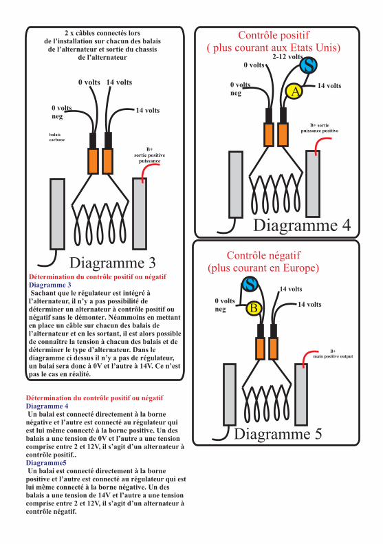
balais carbone
0 voltsneg
14 volts
Diagramme 3
B+ sortie positive
puissance
2 x câbles connectés lorsde l’installation sur chacun des balais
de l’alternateur et sortie du chassisde l’alternateur
14 volts0 volts
Détermination du contrôle positif ou négatif Diagramme 3 Sachant que le régulateur est intégré à l’alternateur, il n’y a pas possibilité de déterminer un alternateur à contrôle positif ou négatif sans le démonter. Néammoins en mettant en place un câble sur chacun des balais de l’alternateur et en les sortant, il est alors possible de connaître la tension à chacun des balais et de déterminer le type d’alternateur. Dans le diagramme ci dessus il n’y a pas de régulateur, un balai sera donc à 0V et l’autre à 14V. Ce n’est pas le cas en réalité.
Diagramme 4
B+ sortiepuissance positive
0 voltsneg
14 volts
2-12 volts 0 volts
Contrôle positif( plus courant aux Etats Unis)
A
s
0 voltsneg
14 volts
Diagramme 5
B+ main positive output
14 volts
B
sContrôle négatif
(plus courant en Europe)
Détermination du contrôle positif ou négatif Diagramme 4
Diagramme5
Un balai est connecté directement à la borne négative et l’autre est connecté au régulateur qui est lui même connecté à la borne positive. Un des balais a une tension de 0V et l’autre a une tension comprise entre 2 et 12V, il s’agit d’un alternateur à contrôle positif..
Un balai est connecté directement à la borne positive et l’autre est connecté au régulateur qui est lui même connecté à la borne négative. Un des balais a une tension de 14V et l’autre a une tension comprise entre 2 et 12V, il s’agit d’un alternateur à contrôle négatif.
Votre satisfaction à 100 % est notre but.
Garanties du produit:
d ’achat. Si vous n ’avez pas cette preuve Nous savons que chaque consommateur est demandez au vendeur qui vous a fourni la unique. Si vous avez un problème, une question, matériel de vous en fournir une nouvelle.un commentaire n ’hésitez pas à nos contacter, Pour faire une réclamation sous garantie, vérifier même si la période de garantie est terminée. le numéro de téléphone sur internet. Nous ferons
les meilleurs efforts pour remplacer ou réparer le Chaque produit fabriqué par Sterling est vendu produit, si il est défectueux suivant les critères de avec une garantie d ’au moins 2 ans, comptée à la garantie.partir de la date d ’achat. Chaque produit est garantie contre des défauts dans les matériaux ou des défauts de fabrication. Nous choisirons de remplacer ou de réparer le produit défectueux pendant la période de garantie. Les conditions suivantes s ’appliquent:
- La preuve de l ’achat doit être fournie, sinon la période de garantie commence à la date de fabrication de l ’objet.- Notre garantie couvre les défauts dans les matériaux et dans la fabrication. Les dommages causés par des négligences, des abus, des accidents, des altérations, une mauvaise utilisation ne sont pas couverts par notre garantie. - La garantie ne s ’applique pas si les dommages proviennent d ’une mauvaise réparation. - Le consommateur est redevable des frais d ’envoi du produit. - Sterling Power renverra le produit à ses frais
Si votre produit a été endommagé pendant le transport, ou si il n ’arrive pas à la bonne destination n ’hésitez à nous contacter rapidement, nous pouvons régler le problème.Ceci ne s ’applique que pour le transport organisé par notre compagnie. Il est préférable de ne pas jeter l ’emballage du produit.
Tout retour doit être accompagné d ’une preuve
Service consommateur et garantie
Sterling Power Products Ltd
ENGLAND www.sterling-power.com
Sterling Power USA www.sterling-power-usa.com
Page 13

Part Number: PDARPart Number:PDARRC
inkl.1 Stk. Batterie-Temperatur-Sensor
1 Stk. Lichtmaschinen-Temperatur-Sensor
optionale Fernbedienung
RoHScompliant
STERLING POWER PRODUCTS
DIGITALER HOCHLEISTUNGSREGLER
Fortschrittliche LadetechnikInstallationsanleitung Deutsch
STERLING POWER PRODUCTSwww.sterling-power.com
www.sterling-power-usa.com
Max. Feldstrom:Bei positiver Einstellung: 10ABei negativer Einstellung: 15A
Vorzugsweise testet man den Strom mit einem DC Zangenamperemeter. Dazu starten sie den Motor, erhöhen die Drehzahl und belasten die Batterien, so dass die Lima maximal arbeitet. Jetzt messen
D.h. es können Lichtmaschinen bis ca. 450A (mit Sie mit einem Zangenamperemeter den Strom.integriertem, parallelem Regler) oder Lichtmaschinen bis 200A (als alleiniger Regler) geregelt werden.
IP67Waterproof
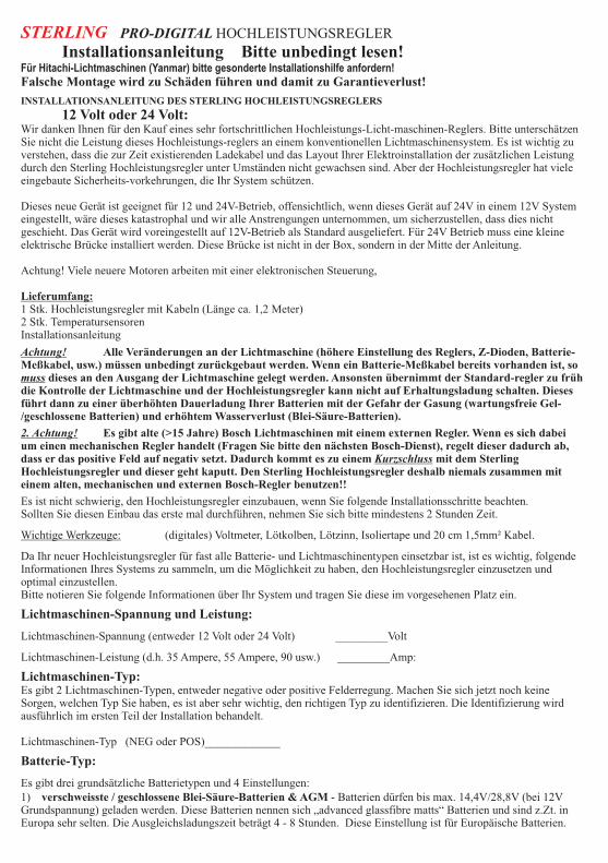
STERLING PRO-DIGITAL HOCHLEISTUNGSREGLER
Installationsanleitung Bitte unbedingt lesen!Für Hitachi-Lichtmaschinen (Yanmar) bitte gesonderte Installationshilfe anfordern!Falsche Montage wird zu Schäden führen und damit zu Garantieverlust!
INSTALLATIONSANLEITUNG DES STERLING HOCHLEISTUNGSREGLERS
12 Volt oder 24 Volt:Wir danken Ihnen für den Kauf eines sehr fortschrittlichen Hochleistungs-Licht-maschinen-Reglers. Bitte unterschätzen Sie nicht die Leistung dieses Hochleistungs-reglers an einem konventionellen Lichtmaschinensystem. Es ist wichtig zu verstehen, dass die zur Zeit existierenden Ladekabel und das Layout Ihrer Elektroinstallation der zusätzlichen Leistung durch den Sterling Hochleistungsregler unter Umständen nicht gewachsen sind. Aber der Hochleistungsregler hat viele eingebaute Sicherheits-vorkehrungen, die Ihr System schützen.
Dieses neue Gerät ist geeignet für 12 und 24V-Betrieb, offensichtlich, wenn dieses Gerät auf 24V in einem 12V System eingestellt, wäre dieses katastrophal und wir alle Anstrengungen unternommen, um sicherzustellen, dass dies nicht geschieht. Das Gerät wird voreingestellt auf 12V-Betrieb als Standard ausgeliefert. Für 24V Betrieb muss eine kleine elektrische Brücke installiert werden. Diese Brücke ist nicht in der Box, sondern in der Mitte der Anleitung.
Achtung! Viele neuere Motoren arbeiten mit einer elektronischen Steuerung,
Lieferumfang:1 Stk. Hochleistungsregler mit Kabeln (Länge ca. 1,2 Meter)2 Stk. TemperatursensorenInstallationsanleitung
Es ist nicht schwierig, den Hochleistungsregler einzubauen, wenn Sie folgende Installationsschritte beachten.Sollten Sie diesen Einbau das erste mal durchführen, nehmen Sie sich bitte mindestens 2 Stunden Zeit.
Wichtige Werkzeuge: (digitales) Voltmeter, Lötkolben, Lötzinn, Isoliertape und 20 cm 1,5mm² Kabel.
Da Ihr neuer Hochleistungsregler für fast alle Batterie- und Lichtmaschinentypen einsetzbar ist, ist es wichtig, folgende Informationen Ihres Systems zu sammeln, um die Möglichkeit zu haben, den Hochleistungsregler einzusetzen und optimal einzustellen.Bitte notieren Sie folgende Informationen über Ihr System und tragen Sie diese im vorgesehenen Platz ein.
Lichtmaschinen-Spannung und Leistung:
Lichtmaschinen-Spannung (entweder 12 Volt oder 24 Volt) _________Volt
Lichtmaschinen-Leistung (d.h. 35 Ampere, 55 Ampere, 90 usw.) _________Amp:
Lichtmaschinen-Typ:Es gibt 2 Lichtmaschinen-Typen, entweder negative oder positive Felderregung. Machen Sie sich jetzt noch keine Sorgen, welchen Typ Sie haben, es ist aber sehr wichtig, den richtigen Typ zu identifizieren. Die Identifizierung wird ausführlich im ersten Teil der Installation behandelt.
Lichtmaschinen-Typ (NEG oder POS)_____________
Batterie-Typ:
Es gibt drei grundsätzliche Batterietypen und 4 Einstellungen:1) verschweisste / geschlossene Blei-Säure-Batterien & AGM - Batterien dürfen bis max. 14,4V/28,8V (bei 12V Grundspannung) geladen werden. Diese Batterien nennen sich „advanced glassfibre matts“ Batterien und sind z.Zt. in Europa sehr selten. Die Ausgleichsladungszeit beträgt 4 - 8 Stunden. Diese Einstellung ist für Europäische Batterien.
Achtung! Alle Veränderungen an der Lichtmaschine (höhere Einstellung des Reglers, Z-Dioden, Batterie-Meßkabel, usw.) müssen unbedingt zurückgebaut werden. Wenn ein Batterie-Meßkabel bereits vorhanden ist, so muss dieses an den Ausgang der Lichtmaschine gelegt werden. Ansonsten übernimmt der Standard-regler zu früh die Kontrolle der Lichtmaschine und der Hochleistungsregler kann nicht auf Erhaltungsladung schalten. Dieses führt dann zu einer überhöhten Dauerladung Ihrer Batterien mit der Gefahr der Gasung (wartungsfreie Gel-/geschlossene Batterien) und erhöhtem Wasserverlust (Blei-Säure-Batterien).
2. Achtung! Es gibt alte (>15 Jahre) Bosch Lichtmaschinen mit einem externen Regler. Wenn es sich dabei um einen mechanischen Regler handelt (Fragen Sie bitte den nächsten Bosch-Dienst), regelt dieser dadurch ab, dass er das positive Feld auf negativ setzt. Dadurch kommt es zu einem Kurzschluss mit dem Sterling Hochleistungsregler und dieser geht kaputt. Den Sterling Hochleistungsregler deshalb niemals zusammen mit einem alten, mechanischen und externen Bosch-Regler benutzen!!

2) GEL-Batterien von EXIDE und VARTA = (wartungsfrei) können keine Gasung vertragen, d.h. eine Spannung über 14,4/28,8 Volt muss unbedingt vermieden werden.Da diese Batterien nur einen sehr geringen Ladestrom akzeptieren, beträgt die Ausgleichsladungszeit 12 - 24 Stunden. (Bitte lesen Sie die Broschüre "EXIDE-GEL - Tipps und Kniffe für ein langes Batterieleben)3) Konventionelle Blei-Säure-Batterien, bei denen Sie Zugang zum Säure-Füllstand haben, um diesen auffüllen zu können. Dieser Batterietyp kann schneller geladen werden, und so kann der Hochleistungsregler auf höchstem Niveau arbeiten. Die Ladeschlussspannung beträgt 14,8 / 29,6V. Dieses ist immer noch der effektivste und günstigste Batterietyp. Die Ausgleichsladungszeit beträgt 1 - 3 Stunden.4) GEL & AGM Batterien (amerikanische Spezifikation)Gem. amerikanischer Spezifikation sollen diese Batterietypen nicht mit mehr als 14,1V/28,2V geladen werden. Die Ausgleichsladungszeit beträgt 4 - 10 Stunden.
Welcher Batterietyp ist auf Ihrer Yacht?
(AGM, Gel/geschlossen oder Normal)________________________
EinbauDieses ist der einzig schwierige Teil, bei dem Sie den Lichtmaschinen-Typ identifizieren müssen. Nach der Identifizierung tragen Sie Ihren Lichtmaschinen-Typ bitte in das dafür vorgesehene Feld ein. Die Identifizierung ist sehr wichtig, da es sehr viele verschiedene Lichtmaschinen gibt und viele dieser von außen nicht zu identifizieren sind. Sie gehen jetzt folgendermaßen vor:
Die Identifizierung des Feld-Kontroll-Kabels: (DF - Anschluss)
Sollten Sie einen „DF“ oder „F“ - Anschluss an Ihrer Lichtmaschine haben, so können Sie diesen nur verwenden, wenn dieser Anschluss direkt auf den Kohlebürstenhalter läuft (keine Kondensatoren oder Dioden dazwischen!). Ansonsten ist dieser Anschluss für den Hochleistungsregler nicht verwendbar. Auch wenn dieser Anschluss entsprech-end verläuft, müssen Sie noch feststellen, ob Ihre Lichtmaschine positiv oder negativ geregelt wird.
Deshalb müssen auch Sie leider die folgenden Schritte abhandeln, damit der Hoch-leistungsregler einwandfrei funktioniert.
(Bitte haben Sie keine Angst bei der Demontage Ihrer Lichtmaschine. Dieses sind einfach aufgebaute Geräte.)
1) Trennen Sie die Batterien von der Stromversorgung. (Dieses muss erfolgen, um einen Unfall mit stromführenden Kabeln unbedingt zu vermeiden.)
2) Entfernen Sie alle Kabel von der Rückseite der Lichtmaschine.Notieren Sie sich unbedingt sorgfältig das Anschlussschema und markieren Sie die Kabel, da Sie diese nach der Installationsroutine wieder anschließen müssen.
3) Nachdem Sie nun alle Kabel entfernt haben, bauen Sie die Lichtmaschine ab. Wenn Sie den Regler so entfernen können, brauchen Sie die Lichtmaschine nicht abbauen. Alle anderen Veränderungen können dann ohne Abbau erfolgen.
4) Nicht so schlimm, oder? (Nun zum
Wir versuchen die 2 Kontakte (Bürstenkontakte) zu erreichen, die dem Rotor den Strom liefern. Diese sind normalerweise am Regler befestigt. Entfernen Sie den Regler von der Rückseite der Lichtmaschine (normalerweise 2 - 4 Schrauben). Beim Ausbau sollte der Regler zusammen mit den 2 Bürstenkontakten herauskommen. So sollte es bei 80% aller Lichtmaschinen wie Lucas, Bosch und Valeo sein.
Wenn dieses nicht so ist, könnte es sich um folgende Abweichungen handeln:
a) Sie besitzen eine bürstenlose Lichtmaschine, meistens eine S.E.V. Marshell 35 Amp. Lichtmaschine, die an alten Volvo- oder Peugeot-Motoren installiert ist. Diese besitzt einen “F” oder “DF” – Anschluss. Hier schließen Sie das weiße Kabel an. Die SEV Marshell 35A ist eine positive Lichtmaschine. Deshalb müssen Sie noch den Regler auf “POS” einstellen. Das braune Kabel geht an denAnschluss „B+“, das gelbe Kabel an den Anschluss “61” und der Rest wie bei allen anderen auch. Gehen Sie weiter mit der “Hochleistungsregler-Einstellung”. Pkt. 5)-9) dürfen Sie überspringen! Der externe Regler kann jetzt entfernt werden. Die schwarzen Kabel des Hochleistungsreglers nicht an Anschluss
Achtung! Wenn Sie mind. eine Gel-/geschlossene Batterie haben, so muss Gel/geschlossen eingetragen werden! Haben Sie mind. eine AGM, so muss AGM eingetragen werden.
Empfehlung! Verwenden Sie die "guten, alten" Blei-Säure Batterien, die nachgefüllt werden können und wo die Säuredichte überprüft werden kann.
schwierigsten Aufgabenteil.)
Hinweis! Sollten Sie sich dieses nicht zutrauen, so beauftragen Sie bitte einen Motorenfachmann oder besser einen Kfz-/Yacht-Elektriker.
“D-” anschließen, sondern direkt an Minus / Masse.
Hinweis!! Wenn Sie mit der SEV Marshell über Trenndioden laden und den Standardregler entfernt haben, dann muss das braune Kabel mit einem der Ausgänge der Trenndiode verbunden werden.

b) Entfernte Regler (Fernregler), einige Lichtmaschinen haben Regler, die entfernt installiert sind und mit der Lichtmaschine durch 3 - 5 Kabel verbunden sind. (gewöhnlich an alten Lichtmaschinen oder an Balmar und Powerline Limas) Diese Kontakte sind an einer Kollektor-/Bürsten-Box an der Lichtmaschine befestigt. Demontieren Sie diese Box, und die Kontakte müßten mit herauskommen. An diesen Kontakten sind 2 Kabel bereits befestigt. Diese Kabel müssen Sie nun verfolgen. Ein Kabel ist das DF-Kabel und das andere liegt entweder gegen Plus oder gegen Minus. Wenn Sie den HLR als alleinigen Regler einsetzen, dann können Sie frei wählen.
HLR als alleinigen Regler:Von den Kohlebürsten kommen 2 Kabel (bei einem Kohlebürstenhalter ohne internen Anschluss).. Legen Sie ein Kabel auf positiv/plus (über eine 5A Sicherung) und das andere Kabel geht an das weiße Kabel des Reglers. Stellen Sie den Regler auf negativ. Es kann auch umgekehrt gemacht werden, aber wir empfehlen dringend diese Version. Pkt. 5)-9) dürfen Sie überspringen.Wenn Sie einen internen aber abgeklemmten Regler haben, und Sie möchten den Sterling Regler als alleinigen Regler einsetzen, dann müssen Sie auch das DF-Kabel herausführen. Meistens geht ein Bürstenkontakt intern direkt auf positiv/plus. Sie müssen die Bürste finden, auf der gegengeregelt wird und die dann unser DF Anschluss ist. Geht eine Bürste intern auf positiv/plus, dann muss der Regler auf "NEG" eingestellt werden.
HLR als parallel-Regler:Verfolgen Sie beide Kabel bis zum Regler. Sie sollten feststellen können, ob eines dieser Kabel auf plus/positiv oder minus/negativ anliegt und das andere Kabel am Regler auf einem Stecker befestigt ist, der mit "Field" oder "F" oder "DF" bezeichnet ist. Genau and dieses Kabel (Field, F oder DF) schließen Sie das weiße Kabel des Reglers mit an. Wenn das andere Kabel der Bürste auf plus/positiv geht, dann muss der Regler auf negativ einstellt werden, ansonsten genau umgekehrt. Überspringen Sie Pkt. 5)-9).
Können Sie beides nicht feststellen, dann gehen Sie bitte ganz normal in dieser Anleitung weiter.
c) Sie haben keinen Anschluss “D+”, sondern nur einen Anschluss “61” oder „L“. Dann sollten Sie an den Anschluss “61” das gelbe Kabel anschließen. Wenn es sich dann um eine positive Lima handelt, dann muss das braune Kabel mit dem Anschluss “B+” verbunden werden. Haben Sie einen „L“ Anschluss, dann können beide Kabel (gelb und braun) auf „L“ gelegt werden. Der Rest wie beschrieben.
c) Yanmar, Hitachi oder Mitsubishi Lichtmaschinen: Bitte fordern Sie die Spezial-Hitachi-Lichtmaschinen-Installationsanleitung bei uns an.
5) Nachdem Sie die Bürstenkontakte gefunden haben, löten Sie ein 100 mm langes 1,5 mm² Kabel an jeden Kontakt der Bürste oder benutzen eventuell vorhandene Steckkontakte.
9) Dieses ist der wichtigste Teil. Während Maschine und Lichtmaschine laufen, müssen Sie mit dem Voltmeter die beiden Kabel durchmessen. (immer gegen Masse/Negativ!!)
Volt: Kabel 1 = ________________ Volt: Kabel 2 = ________________
Wenn ein Kabel eine Spannung von 2 - 11 Volt und das andere von 12 - 14 Volt aufweist, dann hat die Lichtmaschine einen positiven Rotor => (negative Feldregelung) -> Schreiben Sie bitte in das entsprechende Feld “NEG”
Wenn ein Kabel eine Spannung von 2 - 11 Volt und das andere von 0 (null) Volt aufweist, dann hat die Lichtmaschine einen negativen Rotor => (positive Feldregelung) -> Schreiben
In beiden Fällen behalten Sie das 2 - 11 Volt Kabel und entfernen das >12V - 14V oder 0 Volt Kabel.
Trick: Das ganze läßt sich auch ohne Voltmeter feststellen. Dazu benötigen Sie eine 12V oder 24V (Spannung je nach
Hinweis: Lucas Regler-Anschlusskontakte werden aus rostfreiem Stahl hergestellt. Normaler flußmittelhaltiger Lötzinn ist nicht zu gebrauchen. Benutzen Sie Flußmittel aus der Tube und der Lötzinn wird auch hier halten.
6) Nachdem Sie an jeden Bürstenkontakt ein Kabel angelötet haben, markieren Sie diese Kabel bitte mit “Kabel 1” und “Kabel 2” und setzen Sie die Lichtmaschine wieder zusammen. Achten Sie darauf, dass die Kabel nicht scheuern können.
Problem: Bei Volvo Maschinen mit Valeo Lichtmaschinen muss ein kleiner Ausschnitt um den Regler gefeilt oder geschnitten werden, damit die Kabel hindurch passen.
7) Stellen Sie sicher, dass sich die beiden Kabel nicht berühren, und dass diese auch mit der Lichtmaschine nicht in Berührung kommen. Montieren Sie die Lichtmaschine wieder an Ihren Platz.
8) Verbinden Sie die Lichtmaschinen wieder mit allen Kabeln (siehe Pkt. 2). Anschließend starten Sie den Motor. Die Lichtmaschine muss jetzt wie gewohnt arbeiten, da wir keine Veränderungen an dieser oder an der Regelelektronik vorgenommen haben.Das Batteriewarnlicht an Ihrem Schaltbord muss wie vorher gewohnt ausgehen.
Warnung!! Gehen Sie auf keinen Fall in der Installation weiter, solange die Lichtmaschinen nicht wie vorher gewohnt arbeitet.
Sie bitte in das entsprechende Feld “POS”
Achtung! Wenn Sie eine Spannung von über 14,5V/29V messen, überprüfen Sie die Spannung am Ausgang der Lichtmaschine. Mit hoher Wahrscheinlichkeit ist dann ihr Standardregler defekt.

Ihrer Bordnetzspannung) 21W Glühbirne. An diese Glühbirne befestigen Sie 2 längere Kabel. Diese Kabel markieren Sie als “Kabel A” und “Kabel B” Probieren Sie aus, ob die Glühbirne funktioniert. Anschließend schalten Sie die Zündung des Motors ein. Die Ladekontrolleuchte (falls vorhanden) muss leuchten. Jetzt verbinden Sie Kabel A mit Minus von der Batterie. Anschließend stellen Sie mit Kabel B eine Verbindung zu Kabel 1 her. Leuchtet die Glühbirne? Wenn ja, weiter bei [#] . Stellen Sie eine Verbindung zu Kabel 2 her. Leuchtet die Glühbirne? Wenn ja, weiter bei [#]. Verbinden Sie Kabel A mit Plus von der Batterie. Anschließend stellen Sie mit Kabel B eine Verbindung zu Kabel 1 her. Leuchtet die Glühbirne? Wenn ja, weiter bei [#]. Stellen Sie eine Verbindung zu Kabel 2 her. Leuchtet die Glühbirne? Wenn ja, weiter bei [#]. Wenn die Glühbirne bei keiner Probe leuchtet, muss irgendwo ein Fehler sein. Überprüfen Sie alle Kabel!
[#] Sie nehmen das Kabel B wieder ab und achten Sie darauf, dass Kabel 1 und Kabel 2 keinen Kontakt zu Minus/Masse oder Plus herstellen können, wenn der Motor läuft! Jetzt starten Sie den Motor und die Batterien werden wie gewohnt geladen. Lassen Sie den Motor 15 Min. laufen, um sicherzustellen, dass die Batterien voll sind (so wie bisher gewohnt). Die Batterien sollten nicht leer sein, da ansonsten unsere Probe nicht funktioniert. Also, 15 Min. sind vergangen und die Batterien sind Ihrer Meinung nach voll. Im Folgenden achten Sie auf die Leuchtstärke der Glühbirne!!Nun verbinden Sie wiederum Kabel B mit Kabel 1. Die Glühbirne leuchtet. Anschließend verbinden Sie Kabel B mit Kabel 2. Die Glühbirne leuchtet. Das Kabel (Kabel 1 oder Kabel 2), bei dem die Glühbirne nur glimmt, sehr schwach leuchtet oder schwächer leuchtet, ist das DF-Kontrollkabel. Markieren Sie dieses Kabel mit “DF”. Gleichzeitig können Sie beim glimmen oder leuchten der Glühbirne beobachten, dass die Ladeleistung der Lichtmaschine zunimmt und eventuell die Bordnetzspannung etwas ansteigt. Deshalb lassen Sie das Kabel nicht zu lange angeschlossen! Das andere Kabel, bei dem die Glühbirne sehr hell leuchtet, entfernen Sie.Wenn Kabel A mit Minus verbunden ist, dann hat die Lichtmaschine einen positiven Rotor => (negative Feldregelung) -> Schreiben Sie bitte in das entsprechende Feld “NEG”Wenn Kabel A mit Plus verbunden ist, dann hat die Lichtmaschine einen negativen Rotor => (positive Feldregelung)-> Schreiben Sie bitte in das entsprechende Feld “POS”
10) Nachdem Sie nun das Feld-Kontroll-Kabel gefunden und den Feldtyp identifiziert haben ist die schwerste Arbeit vorüber. Nun können Sie den Hochleistungsregler installieren.
HOCHLEISTUNGSREGLER - EINSTELLUNG:(Stellen Sie unbedingt den Hochleistungsregler vor dem Einbau korrekt ein!!)1) Nun sollten Sie den Vorbereitungsabschnitt mit den entsprechenden Daten ausgefüllt haben. Jetzt werde ich Sie durch die Hochleistungsregler - Einstellung führen, und Ihnen dabei erklären, was Sie einstellen.
2) Schrauben Sie den Deckel des Hochleistungsreglers ab (4 Schrauben). Anschließend werden Sie folgende Schalter und Einstellungen auf der grünen Leiterplatte vorfinden.
3) Nun können Sie sich entspannen, denn die Einstellung ist sehr einfach, wenn Sie den folgenden Anweisungen folgen.
Wir beginnen bei:
Schalter:Spannung 24V
Bei einem 24V System muss der Regler zuerst auf 24V eingestellt werden. Ansonsten arbeitet der Regler mit den 12V Einstellungen. Zum Umschalten auf 24V muss der mitgelieferte Jumper auf die Steckkontakte (unter der Plastikkappe unten links) aufgesteckt werden!Schalter:BatterietypDieser Schalter bestimmt den Batterietyp (AGM (Glasfasermatten-Batterien), Gel/geschlossen oder offene Blei-Säure-Batterien). Eine Kontrolle der Einstellung erfolgt durch LED 12 + 13. Wenn die LED 13 leuchtet, dann ist der Regler auf geschlossene Säure und AGM Batterien (max. Ladeschlussspannung 14,4V/28,8V (20°C)) eingestellt. Leuchtet die LED 12 (grün), dann haben Sie GEL Batterien der europäischen Spezifikation (max. Ladeschlussspannung 14,4V/28,8V (20°C)). Leuchtet die LED 13 (gelb), dann haben Sie offene Säure-Batterien (max. Ladeschlussspannung 14,8V/29,6V (20°C). Beim Betrieb in dieser Einstellung müssen Sie regelmäßig Ihren Säure-Füllstand der Batterien kontrollieren. Blinkt die LED 12 (grün) am Anfang und ist anschließend aus, dann haben Sie Gel-Batterien der amerikanischen Spezifikation eingestellt.
Schalter (Sicherung): Lichtmaschinen-Typ (negativ oder positiv)Im ersten Teil der Einbauanleitung haben Sie Ihren Lichtmaschinen-Typ identifiziert und in das entsprechende Feld eingetragen (NEG oder POS). Nun müssen Sie den Hochleistungsregler entsprechend einstellen. Dazu befindet sich eine Sicherung unter der Kappe auf der linken Seite., die in entsprechende Kontakte gesteckt sein muss. Es sind 3
Achtung! Vergewissern Sie sich, dass das entfernte/abgeklemmte Kabel anschließend nicht die Lichtmaschine oder sonstige Teile berühren kann!!
Hinweis: Wenn Sie mehrere Batterien angeschlossen haben, und sich darunter eine oder mehr Gel/geschlossene Batterien befinden, so müssen Sie den Hochleistungsregler auf Gel/geschlossene Batterien einstellen. Ansonsten zerstören Sie sich Ihre Gel/geschlossenen Batterien.
Warnung! Verwenden Sie unter keinen Umständen den Hochleistungsregler an Gel/geschlossenen oder AGM Batterien, wenn während des Betriebs die LED 6 gelb leuchtet.

LED Anzeigen
1) BLAU:
7) ROT:
2) GELB: 8) GRÜN:
3) GRÜN: 9) GELB:
4) GELB
10) GRÜN:
5) ROT:
11) GELB:
6) ROT:
12) GRÜN: 13) GELB: 14)
Alle LEDs blinken:
6) ROT blinkend:
hat eine zu hohe Temperatur (>50°C) gemessen und den Regler deaktiviert. Überprüfen Sie die Temperatur an der Batterie. Eventuell ist eine
Spannung liegt am Gerät an. Wenn Zelle defekt.
diese LED während des Motorbetriebs nicht Hohe interne Temperatur im Regler.
leuchtet, überprüfen Sie die Eventuell ist der Erregerstrom zu hoch für diesen
Spannungsversorgung. Regler.
12V Lichtmaschinen-BetriebHochleistungsladung aktiv.
24V Lichtmaschinen-BetriebAusgleichsladung aktiv. Die Spannung
Standby-Modus: Lichtmaschinen-wird auf der oberen Ladeschlussspannung
Temperatur ist zu hoch (> 90°C) Sobald die Lima (temperaturkompensiert!!!) für die automatisch
abgekühlt ist, schaltet das Gerät wieder zu.berechnete Zeit gehalten.
Überprüfen Sie die Belüftung der Lichtmaschine!! Erhaltungsladung aktiv.
Der Motorraum benötigt eine Zwangsentlüftung!Die Spannung sollte auf den unteren Wert fallen
Batterie-Minus-Spannungs-Fehler! Der (temperaturkompensiert!!!) Der Ladezyklus ist
Spannungsabfall auf dem Minus/Negativ Kabel von abgeschlossen und die Batterie wird geladen
der Lima zur Batterie ist zu hoch. Der Regler ist gehalten.
abgeschaltet. Überprüfen Sie die negativen Unterspannungs-Warnung. Die
Ladekabel und Anschlüsse!Spannung an der Batterie ist gering. Sollte
die LED nicht aus gehen, könnte die Lima
Überhöhte Batterie-Spannung (> 15.5V / 31V)defekt sein und nicht laden.
Dieses kann 3 Ursachen haben:Batterie Typ Anzeige.
1) Der Lima-Standardregler ist defekt. Stoppen Sie umgehend den Motor. Diese Überspannung kann der
Temperatur Sensoren, 2 Stk.Sterling Regler nicht verhindern!!
Ein Sensor ist für die Batterie und der andere 2) Der Hochleistungsregler ist defekt. Wenn dieses
Sensor für die Lichtmaschine.der Fall sein sollte, fällt die Spannung wieder ab,
Die Spannung an der sobald die rote LED leuchtet. Das Gerät sollte zur Lima war höher als 17,5V / 37V. Der Sterling Reparatur eingeschickt werden.Regler hat abgeschaltet. 3) Andere externe Regler (Solar, Wind, etc) sind
Dafür gibt es verschiedene Gründe: defekt und überladen die Batterie.1. Die Kabel sind zu dünn. Verstärken Sie die Der Batterie-Temperatur-Sensor
Batterie Typ Anzeige.
1
2
3
410
8
11
9
5
12
13
Fig 1
67
14

Anschlüsse unter der Kappe:14) GELBES KABEL : 15 & 16 ) SICHERUNG:
17 & 19 ) 2 x SCHWARZE KABEL:
Zündung
Diese 2 Kabel müssen mit dem Minus/Negativ an der Lima
Anschluss an den positiven verbunden werden. Die Kabel sollten so kurz wie Anschluss der Batteriemöglich gehalten werden. Auch dürfen die Kabel
Anschluss NICHT verbunden und als 1 Kabel verlängert werden.an den negativen Anschluss der Batterie DF / Feld Anschluss an die
Anschluss an D+ oder Lima nach der Identifikation der richtigen Kohlebürste.B+ an der Lichtmaschine. B+ ist zu bevorzugen.
Einstellung für positive oder negative Felderregung
23) 24V EINSTELLUNGS-BRÜCKE (nur verbinden, wenn 24V Lichtmaschine vorhanden)24) BATTERIE-TYP EINSTELLUNG: NUR 0 - 3 SIND AKTIV!25) ANSCHLUSS FÜR FERNBEDIENUNG26) ROTES KABEL:
27) SCHWARZ-WEISSES KABEL:
18) WEISSES KABEL:28) BRAUNES KABEL:
20) BATTERIE-TEMPERATUR-SENSOR 29) TEMPERATURSENSORANSCHLUSS
21) LICHTMASCHINEN-TEMPERATUR-SENSOR ANSCHLUSS:22) D+/61/IGN - UNTERBRECHNUNGS-ANSCHLUSS (siehe Anleitung):
FUSE
POS NEG
Alternator field typeselector under lid
29
RemoteControlSocket
Positive or NegativeField control
Fuse
65 74 8
3 92 01
14
15 1716 18
19
22
23
2120
2627 2524
28
Fig 2
LED Anzeigen
1) BLAU:
2) GELB: 3) GRÜN: 4) GELB
Spannung liegt am Gerät an. Wenn diese LED während des Motorbetriebs nicht leuchtet, überprüfen Sie die Spannungsversorgung.
12V Lichtmaschinen-Betrieb24V Lichtmaschinen-BetriebStandby-Modus: Lichtmaschinen-Temperatur ist
zu hoch (> 90°C) Sobald die Lima abgekühlt ist, schaltet

Kontaktschuhe für eine Standard-5-Ampere-Sicherung. Werksseitig ist die Sicherung in dem rechten und mittleren Kontaktschuh befestigt und somit als NEGATIVER Hochleistungsregler eingestellt. Wenn Sie eine negativ geregelte Lichtmaschine eingebaut haben, so lassen Sie die Sicherung in dieser Position. Wenn Sie eine positiv geregelte Lichtmaschine eingebaut haben, so müssen Sie die Sicherung in den mittleren und in dem linken Kontaktfuß stecken. Somit ist ein POSITIVER Hochleistungsregler eingestellt.
des Batterie-Tem
des Lichtmaschinen-Tem
Der Hochleistungsregler sollte so nah wie möglich an der Lichtmaschine installiert werden. Dieses ist vor allem bei Lucas Lichtmaschinen sehr wichtig. Bei Lucas Lichtmaschinen darf das schwarze (negativ) Kabel nicht verlängert werden, da ansonsten die Lichtmaschine anfängt zu pulsieren. Der Einbauort sollte möglichst trocken gewählt werden.Die Kabelverbindungen sind sehr einfach, aber ich werde kurz näher darauf eingehen, welche Funktion jedes einzelne Kabel ausübt.Jedes Kabel sollte über eine Sicherung abgesichert werden. Hierzu eignet sich unserer Sicherungsblock GATC-4848Bitte die Reihenfolge der Erklärung auch beim Anschluss einhalten!! Stromversorgung und Motor sind ausgeschaltet!
Achtung! Die Einstellung muss unbedingt korrekt vorgenommen werden, da mit einer falschen Einstellung der Standard-Lichtmaschinenregler zerstört werden könnte.
Hinweis: Viele, die das Vorgängermodell dieses Reglers kennen, vermissen vielleicht die Einstellung der Ausgleichsladungszeit. Diese Einstellung ist bei diesem Regler nicht mehr nötig. Die Ausgleichsladungszeit wird vollkommen automatisch berechnet und kann bei jedem Ladevorgang anders sein!
Anschluss peratur-Sensors!Der PRO-DIGITAL Hochleistungsregler hat serienmäßig einen Temperatursensor, der dem Regler beiliegt. Wenn dieser Sensor nicht angeschlossen wird, wird von einer Temperatur von 20°C ausgegangen. Ansonsten wird die Ladeschlussspannung temperaturgesteuert, was interessant sein könnte, wenn Ihre Batterien im Motorraum untergebracht sind oder wenn Sie eine Reise in sehr warme oder kalte Gebiete vornehmen wollen. (Generell sind die Batterien unterhalb der Wasserlinie montiert. Dadurch werden die Batterien selbst in sehr warmen Gebieten nicht wärmer als 30°C).Den Sensor schließen Sie mit dem beiliegenden Kabel (Sensor und Kabel) an den Anschluss 20 an. Das Kabel kann in der entsprechenden Kabelstärke bis max. 5m Gesamtkabellänge verlängert werden. Den Sensor selbst können Sie entweder an die Seite einer Ihrer Batterien kleben oder mit dem Kabelschuh an den Negativ-Anschluss einer Ihrer Batterien klemmen. Dadurch wird die Temperatur der Bleiplatten in den Batterien gemessen. Es kann dadurch aber auch vorkommen, dass der Sensor die Temperatur misst, die durch eine schlechte Verbindung entstehen kann. Dann werden Ihre Batterien nicht korrekt geladen, was dann auch zum Nachteil aller Batterien ist.Bei einer Temperatur von ca. 50°C an diesem Sensor schaltet der Hochleistungsregler aufgrund von zu hoher Temperatur ab. Dann blinkt die rote LED 6.
Anschluss peratur-Sensors!Der PRO-DIGITAL Hochleistungsregler hat serienmäßig einen 2. Temperatursensor, der dem Regler beiliegt. Dieser Temperatursensor dient der Überwachung der Lichtmaschinen-Temperatur. Bei einer zu hohen Temperatur der Lichtmaschine (> 90°C), wird der Hochleistungsregler deaktiviert, bis die Temperatur wieder geringer geworden ist. Besonders ist schlecht belüfteten Motorräumen haben Lichtmaschinen, bei hoher Belastung, nicht genügend kühle Luft.Den Sensor schließen Sie mit dem beiliegenden Kabel an den Anschluss 21 an. Das Kabel kann in der entsprechenden Kabelstärke bis max. 5m Gesamtkabellänge verlängert werden. Den Sensor sollten Sie am Gehäuse befestigen. Entweder an einer der Gehäuseschrauben oder mit einer großen Schelle um die Lichtmaschine herum gegen das Gehäuse klemmen.Bei einer Temperatur von mehr als 90°C an diesem Sensor schaltet der Hochleistungs-regler ab, bis die Temperatur wieder abgesunken ist. Die gelbe LED 4 leuchtet solange auf.Wenn dieser Anschluss 21 nicht belegt ist, ist diese Funktion deaktiviert.
Umleitung des D+/“61“/“L“ - Kabels bei Problemenmit der Ladekontrollleuchte im SchaltpanelDieses sollten Sie erst machen, nachdem Sie erste Erfahrungen mit dem Hoch-leistungsregler gemacht haben. Bei einigen neueren Motoren (besonders im PKW-Bereich) kann es vorkommen, dass nach Installation des Hochleistungsregler die Ladekontrollleuchte nicht mehr erlischt, nachdem der Motor gestartet wurde, obwohl die Ladung einwandfrei funktioniert.Dann sollten Sie das D+/“61“/“L“ - Kabel unterbrechen und die Kabel durch den Anschluss 23 legen. Dann wird diese Fehlanzeige nicht mehr vorkommen.Bitte unternehmen Sie diese Veränderung nur, nachdem Sie überprüft haben, dass der Hochleistungsregler einwandfrei funktioniert und die Ladekontrollleuchte trotz der korrekten Funktion der Lichtmaschine und des Reglers nicht erlischt.Anschließend schrauben Sie den Deckel wieder auf den Hochleistungsregler. Jetzt ist der Hochleistungsregler fertig zum Einbau.
Einbauhinweise und Erklärungen:

j
h Tem
pe
ratu
rese
nso
r
f l
a = yellow to ignition (or D+/L/61)b = white to fieldc = brown to alt D+/62/L/DLd = 2 x black to alternator neg.e = split charge diode / relayf = alternatorg = starter batteryh = domestic battery banki = red to domestic batteryj = black/white to battery negativek = temperature sensor to alternatorl = temperature sensor to battery
a
b
g
id
e
Fig 4
POS(+)POS(+)
a = gelb an Zündung+ oder (D+/R/L/DL)b = weiss = Feldc = braun an D+/62/L/DLd = 2 x schwarz an Lima negativ-minuse = Trenndiode oder Relaisf = Lichtmaschineg = Starterbatterieh = Verbraucherbatteriebanki = rot an plus der Referenzbatteriej = schwarz-weiss an minus der Referenzbatteriek = Temperatursensor für die Lichtmaschinel = Temperatursensor der Referenzbatterie
INSTALLATON WITH SPLIT CHARGE DIODE OR RELAY:
k
INSTALLATON MIT TRENNDIODE ODER RELAIS:
Temperature-Sensor
c
if the batteries exceed 15.5V (this will only usually poor cable connections, long cable happen if the standard voltage regulator on the runs or too thin a cable to carry the current alternator is defective or the Advanced now being produced, or, simply a failure in Regulator is defective). The other sensor is the connection between the alternator and connected to the alternators D+ (the brown the batteries. A significant cause is an inline wire), this trips the Regulator if the voltage ammeter. Please be aware of cable runs with exceeds 17.5V at the alternator (all LEDs will ammeters in the system. A good question to flash together). The reasons for this tripping are ask yourself is what is the cable length
1 offene Blei-Säure 14,8V/29,6V 1 - 10 Std. 13,65V/27,3V 0 GEL 14,4V/28,8V 12 - 24 Std. 13,8V/27,6V2 geschlossene Säure/AGM 14,4V/28,8V 4 - 8 Std. 13,65V/27,3V3 GEL (USA) 14,2V/28,4V 4 - 10 Std. 13.8V/27,6V
Position Batterietyp Ladeschluss- Ausgleichs- Erhaltungs LEDspannung ladung spannung
Batterie-Typ Einstellung an dem Drehknopf
FUSE
POS NEG
Alternator field typeselector under lid

light
CE
on/off
beep
1234
2
4
3
1
Power Managementwith
AMP Hr Counter
Sterling power products
Amphr
Amps Volts
14.35 v m Pos 437amps 435 a/hrs
Advanced Alternator RegulatorDisplay and
Diagnostics Panel
Sterling power products CE
on/off
alarm
light
temp
System
Default
Low voltage warning
System Disengaged
System Trip
System Within Limits
Screen
Help
Bat 14.4v TimerAlt 15.4v 134m
set up
volts
temperature sensor cable to negative battery terminal
starter battery
Rot
POS(+)
domesticbattery bank
1 2
COMMON
BOTH
INSTALLATION MIT 2-WEGE SCHALTER
a
bf
g
j
cd
e
h
Fig 5
POS(+)
light
CE
on/off
beep
1234
2
4
3
1
Power Managementwith
AMP Hr Counter
Sterling power products
Amphr
Amps Volts
14.35 v m Pos 437amps 435 a/hrs
Advanced Alternator RegulatorDisplay and
Diagnostics Panel
Sterling power products CE
on/off
alarm
light
temp
System
Default
Low voltage warning
System Disengaged
System Trip
System Within Limits
Screen
Help
Bat 14.4v TimerAlt 15.4v 134m
set up
volts
Yellow to ignition (or D+/L/61)White to Field/DF/F
Optional Fernbedienung
Das rote Kabel muss an den Eingangdes Umschalters angeschlossen werden!
BAT 14.1V BULKALT 14.4V CALC.
BULK CHARGEWET OPEN
SYSTEM SET: 12Vxxx min. ACTIVE
BAT TEMP: 20CALT TEMP: 60C
Fernbedienung Info
A
B
3 Möglichkeiten die FB zu installieren.1) Aufbau mit Rahmen2) Einbau3) Paneleinbau von hinten.
Drücken Sie die „volts“ Taste.Es erscheint die Batterie und die Lichtmaschinen-Spannung.Drücken Sie die Pfeil-TastePushAnschließend wird die Ladestufe und falls vorhanden, die Ausgleichsladungszeit angezeigt.Gleichzeitig wird auch der Batterietyp angezeigt.Drücken Sie die „setup“ Taste.Die Systemspannung und Systemlaufzeit wird angezeigt.Drücken Sie die „temp“ Taste.Lichtmaschinen- und Batterie-Temperatur werden angezeigt.

SCHWARZ 2 x: (Absicherung mit je 5A Sicherungen)Die zwei schwarzen Kabel sind die Negativkabel und müssen mit der Negativ-Masse an der Lichtmaschine oder mit B - (MINUS) an der Lichtmaschine verbunden werden. Beim Verlängern der Kabel müssen immer beide Kabel einzeln verlängert werden.
SCHWARZ-WEISS GESTREIFT: (optional; muss nicht verbunden werden) (Absicherung mit 2A Sicherung)Dieses Kabel ist das Minus/Negativ - Messkabel und sollte mit der Referenzbatterie auf Minus/Negativ verbunden werden. Dieses Kabel überwacht den negativen Spannungsabfall zwischen der Lichtmaschine und der Referenzbatterie. Beträgt der Spannungsabfall mehr als 1,5V auf der negativen Ladungsseite, dann schaltet der Regler ab (Schutzschaltung) und die LED 7 leuchtet
ine und steuert das Erregungsfeld. Das weiße Kabel wird an das Lichtmaschinen-Kontroll-Kabel [DF] angeschlossen, welches Sie im ersten Teil der Installation identifiziert haben (2 - 12 Volt). Dieses Kabel kann während des Betriebs der Lichtmaschine angeschlossen und getrennt werden, um die Wirkung des Hochleistungsreglers ggü. dem herkömmlichen Ladesystem festzustellen. Bei schwächeren Motoren (< 9 PS) kann dieses nötig werden, da durch die Wirkung des Hochleistungsreglers eine starke Belastung des Motors auftreten kann, und es unter Umständen zu einer Verringerung der Fahrtgeschwindigkeit (< 1 kn) kommen kann.
BRAUN: (Absicherung mit 5A Sicherung)Dieses Kabel wird mit dem D+ (plus) oder „61“ oder „R“/"IG" auf der Rückseite der Lichtmaschine verbunden. Gewöhnlich ist eine Kennzeichnung vorhanden. Hiermit wird die Spannung an der Lichtmaschine gemessen. Bei Überspannung (> 18V/32,5V) schaltet der Hochleistungsregler automatisch ab (ÜBERSPANNUNGS-SCHUTZ AN!) um eine Zerstörung der Lichtmaschine oder Batterien zu vermeiden. (Sicherheitsfunktion!)Wenn der Hochleistungsregler als alleiniger Regler eingesetzt wird und die Regelung positiv ist, dann muss das braune Kabel mit B+ verbunden werden, solange keine Trenndioden eingesetzt werden, ansonsten muss es mit Plus der Batterie verbunden werden, denn sonst kann der Regler nicht richtig regeln, da D+ zum Starten nicht genügend Strom über die Ladekontrollleuchte liefern kann, um den Kreislauf in der Lima starten zu können. Dann funktioniert allerdings der Überspannungsschutz der Lima nicht, wenn das braune Kabel am Pluspol der Batterie anliegt.
Wenn möglich, sollte der Regler gegen NEGATIV / Masse regeln, wenn der Hochleistungsregler als alleiniger Regler eingesetzt wird.
ROT: (Absicherung mit 2A Sicherung)Das rote Kabel ist der Batterie-Spannungs-Fühler. Mit diesem Kabel wird die Batteriespannung gemessen und die Lichtmaschine entsprechend geregelt. Es dient auch dazu, bei Überspannung (> 15,5V/31,5V) den Hochleistungsregler von der Lichtmaschine zu trennen (ÜBERSPANNUNGS-SCHUTZ AN!), um eine Zerstörung der Batterien und Lichtmaschine durch diesen Regler zu ver
Der Anschlusspunkt des roten Kabels ist abhängig von Ihrer gegenwärtigen Verkabelung der Batterien.A: Trenndioden: (sinnvollste Schaltung mit dem Sterling Hochleistungsregler)Wenn Ihre Batterien durch Trenndioden getrennt sind, dann muss das rote Batterie-Spannungs-Mess-Kabel an der Batteriebank angeschlossen werden, an der die größere Batteriekapazität vorhanden ist. (Gewöhnlich die Bordnetzbatterien.) Wenn beide Seiten die gleichen Kapazitäten haben, so kann der Anschluss wahlweise gelegt werden.B: Schaltrelais:Wenn Sie ein Schaltrelais benutzen, gilt dasselbe wie oben. Generell wird die größte Batteriebank zur Messung verwendet. Es sollte auch darauf geachtet werden, dass das rote Kabel an die Batterie angeschlossen wird, die zuletzt durch das Schließen des Relais geladen wird.
C: Wechselschalter:Viele Yachten besitzen einen Wechselschalter, um zwischen den Batterien hin- und herschalten zu können. Bei einem Wechselschalter muss das rote Kabel an den Dauer-Plus-Kontakt, also an den Kontakt, an dem das Lade-
Achtung! Verbinden Sie NIEMALS das schwarze Kabel mit dem B + (plus) Anschluss! Nur den B- (minus) Anschluss verwenden!
WEISS:(Absicherung mit 5A Sicherung)Das weiße Kabel dient zur Kontrolle der Lichtmasch
Achtung! Lassen Sie NIEMALS das weiße Kabel PLUS oder MINUS/MASSE direkt berühren. Durch Kontakt mit PLUS oder MINUS/MASSE kommt es zu einem Kurzschluss und der eingebaut Transistor wird zerstört. Dieser Kurzschluss fällt nicht unter die Garantiebestimmungen. Sollte Ihnen dieses passiert sein, so können Sie einen Transistor bei uns erwerben und diesen neu einlöten (lassen). Wenn bei korrektem Anschluss die Spannung über 15V geht und erst der Regler durch “Hochspannungsschutz an” – LED 6 abschaltet, dann ist im Regelfall der Transistor durch einen Kurzschluss zerstört worden.
hindern. (Sicherheitsfunktion!)
Achtung! Dieses Kabel darf während des Betriebes nicht abgenommen und vom Hochleistungsregler getrennt werden, da ansonsten der Hochleistungsregler keine Referenzspannung erhält und die Lichtmaschine ganz hoch ausregelt. Ihre Batterien und Kabel könnten sofort zerstört werden!
Hinweis: Bei einem billigen Relais kann es zum Verschmelzen der Kontakte kommen, da das Relais eventuell den neuen Belastungen nicht gewachsen ist.
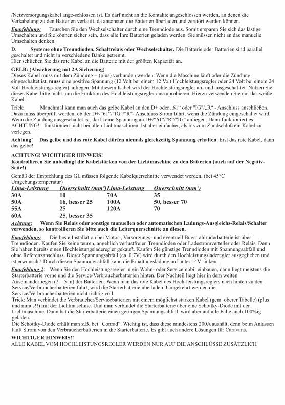
/Netzversorgungskabel ange-schlossen ist. Es darf nicht an die Kontakte angeschlossen werden, an denen die Verkabelung zu den Batterien verläuft, da ansonsten die Batterien überladen und zerstört werden können.
D: Systeme ohne Trenndioden, Schaltrelais oder Wechselschalter. Die Batterie oder Batterien sind parallel geschaltet und nicht in verschiedene Bänke getrennt.Hier schließen Sie das rote Kabel an die Batterie mit der größten Kapazität an.
GELB: (Absicherung mit 2A Sicherung)Dieses Kabel muss mit dem Zündung + (plus) verbunden werden. Wenn die Maschine läuft oder die Zündung eingeschaltet ist, muss eine positive Spannung (12 Volt bei einem 12 Volt Hochleistungsregler oder 24 Volt bei einem 24 Volt Hochleistungs-regler) anliegen. Mit diesem Kabel wird der Hochleistungsregler an- und ausgeschal-tet. Nutzen S
WICHTIGER HINWEIS!!ALLE KABEL VOM HOCHLEISTUNGSREGLER WERDEN NUR AUF DIE ANSCHLÜSSE ZUSÄTZLICH
Empfehlung: Tauschen Sie den Wechselschalter durch eine Trenndiode aus. Somit ersparen Sie sich das lästige Umschalten und Sie können sicher sein, dass alle Ihre Batterien geladen werden. Sie müssen nicht an das manuelle Umschalten denken.
ie dieses Kabel bitte nicht, um die Funktion des Hochleistungsregler auszuprobieren. Hierzu verwenden Sie nur das weiße Kabel.
Trick: Manchmal kann man auch das gelbe Kabel an den D+ oder „61“ oder "IG"/„R“ - Anschluss anschließen. Dazu muss überprüft werden, ob der D+/“61“/"IG"/“R“- Anschluss Strom führt, wenn die Zündung eingeschaltet wird. Wenn die Zündung ausgeschaltet ist, darf keine Spannung an D+/“61“/“R“/"IG" anliegen. Dann funktioniert es. ACHTUNG! - funktioniert nicht bei allen Lichtmaschinen. Ist aber einfacher, als bis zum Zündschloß ein Kabel zu verlegen.
Achtung! Das gelbe und das rote Kabel dürfen niemals gleichzeitig Spannung erhalten. Erst das rote Kabel, dann das gelbe!
ACHTUNG! WICHTIGER HINWEIS!Kontrollieren Sie unbedingt die Kabelstärken von der Lichtmaschine zu den Batterien (auch auf der Negativ-Seite!)
Gemäß der Empfehlung des GL müssen folgende Kabelquerschnitte verwendet werden. (bei 45°C Umgebungstemperatur)Lima-Leistung Querschnitt (mm²)Lima-Leistung Querschnitt (mm²)30A 10 70A 3550A 16, besser 25 100A 50, besser 7055A 25 120A 7060A 25, besser 35Achtung: Wenn Sie Relais oder sonstige manuellen oder automatischen Ladungs-Ausgleichs-Relais/Schalter verwenden, so kontrollieren Sie bitte auch die Leiterquerschnitte an diesen.
Empfehlung: Die beste Installation bei Motor-, Versorgungs- und eventuell Bugstrahlruderbatterie ist über Trenndioden. Kaufen Sie keine teuren, angeblich verlustfreien Trenndioden oder Ladestromverteiler oder Relais. Denn Sie haben bereits einen Hochleistungsladeregler gekauft. Kaufen Sie günstige Trenndioden mit Spannungsabfall und ohne Referenzanschluss. Dieser Spannungsabfall (ca. 0,7V) wird durch den Hochleistungsladeregler ausgeglichen und ist erwünscht! Durch diesen Spannungsabfall kann die Erhaltungsladung auf unter 14V sinken.
Empfehlung 2: Wenn Sie den Hochleistungsregler in ein Wohn- oder Servicemobil einbauen, dann liegt meistens die Starterbatterie vorne und die Service/Verbraucherbatterien hinten. Der Nachteil liegt hier in dem weiten Auseinanderliegen (2 – 5 m) der Batterien. Wenn man das rote Kabel des Hoch-leistungsreglers nach hinten zu den Service/Verbraucherbatterien führt, wird die Starterbatterie überladen. Umgekehrt werden die Service/Verbraucherbatterien nicht richtig voll.Trick: Man verbindet die Verbraucher/Servicebatterien mit einem möglichst starken Kabel (gem. oberer Tabelle) (plus und minus!!) mit der Lichtmaschine. Und man verbindet die Starterbatterie über eine Schottky-Diode mit der Lichtmaschine. Dann hat die Starterbatterie einen geringen Spannungsabfall, wird aber auf alle Fälle auch 100%ig geladen.Die Schottky-Diode erhält man z.B. bei “Conrad”. Wichtig ist, dass diese mindestens 200A aushält, denn beim Anlassen läuft Strom von den Verbraucherbatterien in die Starterbatterie. Es gibt auch andere Lösungen für Caravans.

ANGESCHLOSSEN! DIE VORHANDENEN KABEL DER LIMA WERDEN NICHT UNTERBROCHEN
ODER ENTFERNT!
Funktionstest:Starten Sie die Maschine wie gewöhnlich. Die grüne LED 8 „HIGH CHARGE ON“ und die LED1 „UNIT ACTIVE“ sollten leuchten. Ebenso die LED 12 + 13 „BATTERY TYPE“ in der Farbe, wie Sie den Batterietyp eingestellt ha
Die Batteriespannung nun langsam ansteigen. Dieses kann zwischen 1 Minute und mehreren Stunden dauern, abhängig von dem Ladezustand der Batterien und der Leistung der Lichtmaschine. Bei einer Spannung von 14,2V/28,4V (20°C) die LED 9 „TIMER ACTIVE“
Wartung der Batterien:Gel-/geschlossene Batterien brauchen wie bisher nicht gewartet werden.
Wenn Sie normale Blei-Säure-Batterien und den Hochleistungsregler entsprechend eingestellt haben, so werden Sie einen geringfügig erhöhten Wasserverbrauch feststellen können. Bitte prüfen Sie deshalb in regelmäßigen Abständen den Säure-Füllstand Ihrer Batterien.
FRAGEN UND ANTWORTEN:Frage Ich habe beide Kabel angelötet. Die Lichtmaschine hat einen entfernten Regler. Wenn ich die Kabel durchmesse, dann hat Kabel 1 eine Spannung von 0 Volt und Kabel 2 von 12V. Sobald ich die Drehzahl erhöhe, erhöht sich die Spannung auf 14,1V auf Kabel 2, Kabel 1 bleibt bei 0V. Welchen Erregungstyp habe ich?
Antwort: Ihre Lichtmaschine ist positiv geregelt. Sie stellen den Regler auf “POS”. Wir empfehlen das braune Kabel an den Anschluss “B+” an der Lichtmaschine anzuschließen.Frage: Ich habe eine SEV Marshall Lichtmaschine. Kann ich den Standardregler abbauen und nur mit dem Sterling – Regler arbeiten?Antwort: Ja, Sie können nur mit dem Sterling – Regler arbeiten. Dann haben Sie zwar keinen Notfallregler, aber die Ladestufen werden jetzt nur noch durch den Sterling – HLR geregelt. Der Standardregler kann nicht mehr überregeln (in der Erhaltungsladung). Der Sterling – HLR kann generell bei allen Lichtmaschinen als einziger Regler eingesetzt werden, außer bei BALMAR und POWERLINE.Frage: Ich besitze eine Starter- und eine Verbraucherbatterie. Diese werden über eine Trenndiode geladen. Das
S
ben.
Achtung! Wenn die LED 12 + 13 „GELB + GRÜN“ leuchtet und mindestens eine Gel-/geschlossene Batterie oder AGM angeschlossen ist, so schalten Sie sofort den Motor oder den Hochleistungsregler ab. Die AGM oder Gel-/geschlossenen Batterien können durch eine zu hohe Spannung zerstört werden. Gehen Sie bitte zurück zur Hochleistungsregler - Einstellung.
muss
muss aufleuchten.
Achtung! Die Batteriespannung sollte unbedingt an dem Anschlusspunkt des roten Kabels mit einem digitalen und geeichten Meßinstrument gemessen werden. Hierzu eignet sich besonders gut die STERLING “Batterie-Management-Anzeige (SPM2)”, mit der bis zu 4 verschiedene Spannungsquellen, bis zu 4 verschiedene Stromstärken gemessen werden können und gleichzeitig ist ein Amperestundenzähler integriert. Diese ist klein und handlich, und kann somit auch auf Yachten installiert werden.
Je nachdem, welcher Batterietyp eingestellt ist, wird die Spannung weiter ansteigen oder auch nicht! Abhängig auch von der Batterietemperatur oder besser gesagt von der Temperatur am Sensor. Nach dem Aufleuchten der LED 2 beginnt die Phase der „Ausgleichsladung“. Diese Zeitphase wird jedesmal automatisch berechnet und kann sehr unterschiedlich ausfallen. Am Ende erlischt sowohl die LED 8 als auch die LED 9. Dafür beginnt die LED 10 „FLOAT MODE“ an zu leuchten. Dann ist der Regler in der Erhaltungsladungsphase, die bei ca. 13,3 bis 13,8V liegen sollte.
Achtung! Wenn am Ende nur die LED 10 “FLOAT MODE“ leuchtet und die Spannung über 14 Volt liegt, dann liegt dieses an Ihrem eingebauten oder externen Standardregler. Dieser Regler regelt dann eine höhere Spannung aus und übernimmt die Steuerung der Lichtmaschine. Bitte überprüfen Sie, dass von dem Standardregler keine Meßkabel an die Batterien führen, und alle selbstgebauten Veränderungen (Dioden, etc.) zurückgebaut wurden. Wenn ein Meßkabel vorhanden ist, so muss dieses auf den positiven (Lade-) Ausgang der Lichtmaschine gelegt werden. Sollte die Spannung des Standardreglers weiterhin über der Erhaltungsspannung des STERLING Hochleistungsreglers liegen, bauen Sie eine Trenndiode mit Spannungsabfall ein.
Hinweis: Das Produkt besitzt eine Zwei-Jahres-Garantie, wenn keine als die hier beschriebenen Veränderungen und Einstellungen vorgenommen wurden und entsprechend dieser Einbauanleitung vorgegangen wurde. Bei Veränderungen an der Leiterplatte oder unsachgemäßer Handhabung erlischt diese Garantie.Die Garantie kann beim Hersteller geltend gemacht werden.

rote Kabel liegt an der Verbraucherbatterie an. Es geschieht folgendes: An der Verbraucherbatterie liegen korrekt 14,4V an, aber an der Starterbatter liegen 15,1V an. Wo liegt der Fehler:Antwort: Es gibt 2 Möglichkeiten:1. Die Trenndiode ist auf der einen Seite defekt und dadurch gibt es keinen Spannungsabfall zur Starterbatterie. Dieses können Sie überprüfen, indem Sie die Ausgänge der Trenndiode zu der Verbraucher und zur Starterbatterie tauschen. Sollte dann die Starterbatterie nicht mehr 15,1V haben, dann haben Sie den Fehler gefunden und müssen die Trenndiode austauschen.2. Die Starterbatterie bekommt irgendwo anders Ladestrom her. Oftmals über das positiv Starterkabel zum Anlasser. Häufig ist ein Kabel zwischen der Lichtmaschine (+) und dem Anlasser (+) montiert. Dieses können Sie überprüfen, indem Sie das Ladekabel zur Starterbatterie von der Trenndiode entfernen. Jetzt dürfte die Starterbatterie nicht geladen werden und die Spannung bei 12,6V bleiben, wenn der Motor läuft. Steigt die Spannung hier trotzdem an, dann wird die Batterie logischweise über ein anderes Kabel mit Ladestrom versorgt. Suchen Sie dieses Kabel und entfernen Sie es (oftmals das Kabel von der Lichtmaschine zum Anlasser). Frage: Ich besitze eine Starter-, zwei Verbraucher- und eine Bugstrahlruderbatterie. Die Batterien werden über eine Trenndiode mit 3 Ausgängen geladen. Alle Batterien sind wartungsfreie Batterien von Vetus. Der Regler ist auf GEL eingestellt Das rote Kabel zur Spannungsinformation ist an den Verbraucherbatterien angeschlossen. Alle Kabel haben einen Kabeldurchmesser gemäß Ihrer Empfehlung.Folgendes Problem: Die Spannung an der Bugstrahl und an der Starterbatterie liegt bei 14,5V, an den Verbraucherbatterien bei 14,4V. Nun sollen aber die wartungsfreien Batterien nicht höher als 14,4V geladen werden.Was soll ich tun?Antwort: Generell ist diese Erscheinung korrekt und unproblematisch, da die Starter- und Bugstrahlbatterie keine hohe Ladeleistung bei einer Spannung von 14,5V erhalten. Würde es sich um offene Bleibatterien bei der Bugstrahl- und Starterbatterie handeln, dann wäre es absolut unproblematisch.Die Lösung besteht nun darin, dass das rote Kabel auf die Starterbatterie gelegt werden sollte. Dann bekommen die Verbraucherbatterien eine etwas geringere Ladeschlussspannung.Frage: Nach der Hochleistungsladung sinkt die Ladespannung nicht auf die 13,8V ab, sondern bleibt bei 14,2V. Was sollte ich tun?Antwort: Ihre Lichtmaschine arbeitet mit einem Standardregler und mit dem Sterling Hochleistungsregler. Bei Ihnen passiert folgendes: Nach der Hochleistungsladung übernimmt der Standardregler die Ladefunktion und läßt die Spannung nicht absinken. Der Sterling Regler hat gar keinen Einfluß mehr.Bitte installieren Sie eine einfach, billige Trenndiode mit Spannungsabfall. Dadurch den Spannungsabfall an der Trenndiode, werden die Batterien durch den Standardregler nur noch bis 13,5V geladen. Der Sterling Hochleistungsregler kann jetzt alle 4 Stufen korrekt abarbeiten, und nach Beendigung der Ladung kann der Hochleistungsregler korrekt in die Erhaltungsladung von 13,7 - 13,8V schalten.Eine andere Möglichkeit wäre, den Standardregler abzuklemmen und nur noch mit dem STERLING Hochleistungsregler zu arbeiten. Dann haben Sie aber kein Sicherheits-Backup-System mehr.Frage: Nach Installation des Sterling Hochleistungsregler habe ich stärkere Störungen im Kurz- und Mittelwellenbereich. Was kann ich dagegen tun?Antwort: Jede Lichtmaschine erzeugt Hochfrequenzstörungen. Dabei agieren alle aus der Lichtmaschine kommenden Kabel als Antenne. Es gibt jetzt verschiedene Möglichkeiten diese Störungen einzuschränken. Wir listen diese der Reihe nach auf. Nach jedem Punkt überprüfen Sie bitte, ob sich etwas geändert hat. Zuerst sollten Sie allerdings den Hochleistungsregler abklemmen und die Störungen durch den Standardregler feststellen. Sollten die Störungen identisch sein, so ist nicht der Sterling Hochleistungsregler schuld an den Störungen, sondern der Standardregler. Wenn es der Hochleistungsregler ist, dann sollten Sie alle folgenden Punkte befolgen.Bitte überprüfen Sie zuerst die Erdung aller Geräte, die eine Störung empfangen. Oftmals sind die Störungen schon durch eine gute Erdung behoben.1. Überprüfen Sie, dass alle Empfangs- und Sendegeräte nicht in der Nähe der Ladekabel eingebaut sind (mind. 100cm Abstand!!). Wir meinen die Ladekabel von der Lichtmaschine zu den Batterien. Gleiches kann übrigens auch beim LandAnschluss-Ladegerät von Bedeutung sein.2. Verkürzen Sie die Kabel zwischen dem Hochleistungsregler und der Lichtmaschine so stark wie möglich. Sollten Sie einen externen Standardregler haben, so sollten Sie auch diese Kabel so kurz wie möglich halten.3. Verdrehen Sie alle Kabel aus dem Hochleistungsregler miteinander. Genauso auch mit den Kabeln eines externen Standardreglers.4. Umwickeln Sie die Kabel vom Hochleistungsregler zur Lichtmaschine mit einem Kabel (1 mm²), so dass die Kabel vollständig umwickelt sind. Anschließend verbinden Sie beide Enden dieses Kabels mit der Erdung Ihrer Yacht. Gleiche Prozedur auch bei einem externen Standardregler.5. Installieren Sie einen Hochfrequenzfilter in die Ladeleitung, so dicht wie möglich hinter der Lichtmaschine.6. Installieren Sie einen Hochfrequenzfilter vor den elektronischen Geräten.
Viel mehr kann man nicht tun. Sollten Sie noch weitere Vorschläge haben, so wären wir Ihnen sehr dankbar, wenn Sie uns diese mitteilen würden.Frage: Die Spannung an den Batterien schwankt ungemein. Generell zwischen 13 und 15V. Woran kann das liegen?Antwort: Fast immer liegt es an einem falschen Anschluss der Hochleistungsreglers. Kontrollieren Sie die 2 schwarzen Kabel. Diese müssen mit der Masse/Minus/Negativ der Lichtmaschine verbunden sein. Wenn die schwarzen Kabel

verlängert wurden, müssen diese einzeln verlängert werden! Überprüfen Sie, ob eine eventuelle Verlängerung der Kabel vorgenommen wurde und ob die Kabel einzeln verlängert wurden. Anschliessend kontrollieren Sie das weiße Kabel. Überflüssige Kabellängen sollten entfernt werden. Wenn diese Punkte beachtet wurden, sollte die Spannung ohne Schwankungen anliegen.
Installations- und Bedienungsanleitung
der Fernbedienung und Anzeige des PRO-DIGITALEN Hochleistungsreglers.
Wir danken Ihnen zu dem Kauf unserer Fernbedienung für den Pro-Digitalen Hochleistungsregler. Wir haben viel Zeit und Mühe investiert, um möglichst viele Funktionen zu verwirklichen.
Lieferumfang:Fernbedienung / Anzeige inkl. Aufbaurahmen.Kabel (ca. 8 Meter)
Benötigte Werkzeuge und Teile:Stichsäge (bei Einbaumontage)12mm Bohrer (bei Aufbaumontage2mm Bohrer4 Stk. 45x3mm SenkkopfschraubenKreuz-Schraubenzieher
Ort der Inbetriebnahme
Installieren Sie den Batterie-Management-Controller an einem trockenen Ort. Wählen Sie diesen Ort so, dass Sie jederzeit die Anzeige ablesen können und auch die Schalter bedienen können.
=> ORT MUSS TROCKEN SEIN!!
Der Installationsort muss leicht zugänglich sein!
Nun müssen Sie sich entscheiden,ob Sie das Gerät als Aufbau- Einbau- oder Hinterbaugerät verwenden wollen.
Als Aufbaugerät:
Bohren Sie ein Loch für das Kabel in die Rückwand. Anschießend markieren Sie die Bohrlöcher für die Befestigungsschrauben. Dazu schieben Sie die rechte und linke Abdeckkappe (A) seitlich vom Gerät ab. Bitte keine Gewalt anwenden, da diese aus Kunstoff bestehen und die Führungsrillen brechen können. Nach dem Abschieben können Sie die Befestigungslöcher sehen. Markieren Sie die Bohrlöcher mit den mitgelieferten Schrauben. Verbinden Sie die rückseitigen Anschlüsse mit den Kabeln und befestigen Sie anschließend das Gerät mit den gelieferten Schrauben.
Als Einbaugerät:
Entfernen Sie die Aufbauverblendung (B) von dem Gerät durch Abziehen nach hinten.
Diese Aufbauverblendung (B) können Sie nun sehr einfach als Einbauschablone benutzen. Halten Sie die Einbauschablone an den gewünschten Einbauort. Jetzt zeichnen Sie mit einem Bleistift den inneren Ausschnitt nach.
Sägen Sie den Ausschnitt sehr vorsichtig und genau, denn die Abdeckung der Kante ist nicht sehr breit.
Anschließend verbinden Sie das Kabel mit dem Gerät und dann schieben Sie das Gerät in die von Ihnen gesägte Öffnung und schrauben es mit 4 kurzen Schrauben mit Senkkopf fest. Achten Sie darauf, dass die Schrauben versenkt sind, denn sonst passt die Abeckkappe (A) nicht über die Schrauben. Anschließend schieben Sie die Abdeckkappen (A) über die Schrauben.
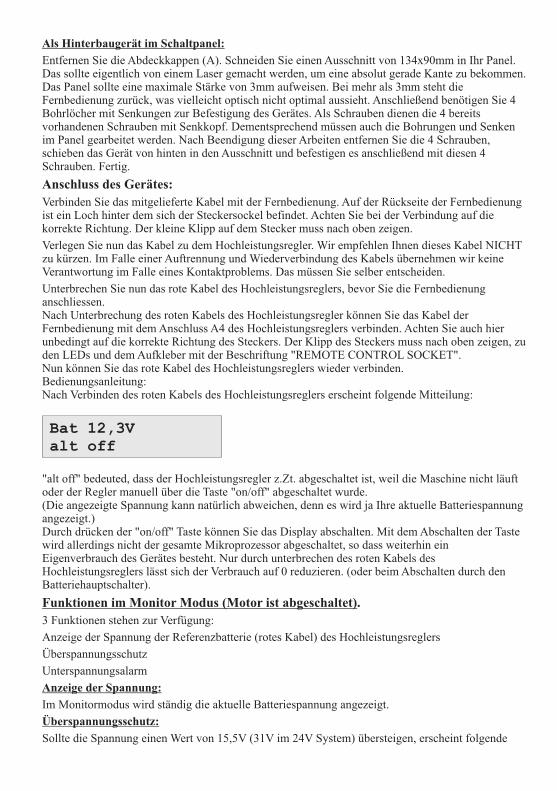
Als Hinterbaugerät im Schaltpanel:
Entfernen Sie die Abdeckkappen (A). Schneiden Sie einen Ausschnitt von 134x90mm in Ihr Panel. Das sollte eigentlich von einem Laser gemacht werden, um eine absolut gerade Kante zu bekommen. Das Panel sollte eine maximale Stärke von 3mm aufweisen. Bei mehr als 3mm steht die Fernbedienung zurück, was vielleicht optisch nicht optimal aussieht. Anschließend benötigen Sie 4 Bohrlöcher mit Senkungen zur Befestigung des Gerätes. Als Schrauben dienen die 4 bereits vorhandenen Schrauben mit Senkkopf. Dementsprechend müssen auch die Bohrungen und Senken im Panel gearbeitet werden. Nach Beendigung dieser Arbeiten entfernen Sie die 4 Schrauben, schieben das Gerät von hinten in den Ausschnitt und befestigen es anschließend mit diesen 4 Schrauben. Fertig.
Anschluss des Gerätes:
Verbinden Sie das mitgelieferte Kabel mit der Fernbedienung. Auf der Rückseite der Fernbedienung ist ein Loch hinter dem sich der Steckersockel befindet. Achten Sie bei der Verbindung auf die korrekte Richtung. Der kleine Klipp auf dem Stecker muss nach oben zeigen.
Verlegen Sie nun das Kabel zu dem Hochleistungsregler. Wir empfehlen Ihnen dieses Kabel NICHT zu kürzen. Im Falle einer Auftrennung und Wiederverbindung des Kabels übernehmen wir keine Verantwortung im Falle eines Kontaktproblems. Das müssen Sie selber entscheiden.
Unterbrechen Sie nun das rote Kabel des Hochleistungsreglers, bevor Sie die Fernbedienung anschliessen.Nach Unterbrechung des roten Kabels des Hochleistungsregler können Sie das Kabel der Fernbedienung mit dem Anschluss A4 des Hochleistungsreglers verbinden. Achten Sie auch hier unbedingt auf die korrekte Richtung des Steckers. Der Klipp des Steckers muss nach oben zeigen, zu den LEDs und dem Aufkleber mit der Beschriftung "REMOTE CONTROL SOCKET".Nun können Sie das rote Kabel des Hochleistungsreglers wieder verbinden.Bedienungsanleitung:Nach Verbinden des roten Kabels des Hochleistungsreglers erscheint folgende Mitteilung:
"alt off" bedeuted, dass der Hochleistungsregler z.Zt. abgeschaltet ist, weil die Maschine nicht läuft oder der Regler manuell über die Taste "on/off" abgeschaltet wurde.(Die angezeigte Spannung kann natürlich abweichen, denn es wird ja Ihre aktuelle Batteriespannung angezeigt.)Durch drücken der "on/off" Taste können Sie das Display abschalten. Mit dem Abschalten der Taste wird allerdings nicht der gesamte Mikroprozessor abgeschaltet, so dass weiterhin ein Eigenverbrauch des Gerätes besteht. Nur durch unterbrechen des roten Kabels des Hochleistungsreglers lässt sich der Verbrauch auf 0 reduzieren. (oder beim Abschalten durch den Batteriehauptschalter).
Funktionen im Monitor Modus (Motor ist abgeschaltet).
3 Funktionen stehen zur Verfügung:
Anzeige der Spannung der Referenzbatterie (rotes Kabel) des Hochleistungsreglers
Überspannungsschutz
Unterspannungsalarm
Anzeige der Spannung:
Im Monitormodus wird ständig die aktuelle Batteriespannung angezeigt.
Überspannungsschutz:
Sollte die Spannung einen Wert von 15,5V (31V im 24V System) übersteigen, erscheint folgende
Bat 12,3Valt off

Meldung
:
Gleichzeitig leuchtet auch die rote LED "System Trip" auf.
Durch drücken der Taste "Volts" kommen Sie wieder in die Spannungsanzeige zurück und die aktuelle Spannung wird angezeigt.
Durch drücken der Taste " "̄ wird ein englischer Hilfstext angezeigt. Dieser Text bezieht sich allerdings auf einen Fehler im Zusammenhang mit dem Hochleistungsregler. In diesem Fall ist der Fehler auf ein anderes Problem zurückzuführen. Eventuell ist das Ladegerät defekt oder ein anderer Fehler im System.
Unterspannungsschutz:
Sollte die Spannung einen Wert von 12V (24V) oder weniger aufweisen, erscheint folgenden Meldung:
Gleichzeitig leuchtet die gelbe LED "Low voltage warning" auf.
Durch drücken der Taste "Volts" kommen Sie wieder in die Spannungsanzeige zurück und die aktuelle Spannung wird angezeigt.
Durch drücken der Taste " "̄ wird ein englischer Hilfstext angezeigt. Die Batterien sollten dringend geladen werden.
Ist die Spannung für mehr als 5 Minuten unter einem Wert von 11,5V (23V) ertönt ein Alarmton. Die Batterien sind jetzt zu mehr als 80% entladen. Die Batterien sollten dringend geladen werden.
Durch drücken der Taste "alarm" lässt sich der Warnton ausschalten.
Sollte die Spannung einen Wert von 12V wieder übersteigen, verschwinden die Warnhinweise umgehend wieder.
Funktionen im Betriebsmodus (Motor läuft):
Ein- und Ausschalten des Hochleistungsreglers:
Mit der Taste "on/off" lässt sich der Hochleistungsregler manuell ein- als auch ausschalten. Wenn Sie die zusätzliche Leistung des Hochleistungsreglers zu einem gewünschten Zeitpunkt nicht wünschen, drücken Sie die Taste "on/off" und der Hochleistungsregler ist abgeschaltet.
Wenn der Hochleistungsregler abgeschaltet ist, jedoch die Anzeige noch sichtbar ist, schaltet sich der Regler automatisch wieder beim nächsten Start des Motors ein.
Drücken Sie die "on/off" ein zweites Mal, schaltet der Regler und die Anzeige ab. Der Regler ist jetzt solange abgeschaltet, bis Sie diesen wieder manuell mit der Taste "on/off" einschalten.
Betrieb des Hochleistungsreglers:Beim Betrieb des Hochleistungsreglers erscheint folgende Anzeige
High batteryvoltage trip
Low batteryvolts warning
BAT 14.1V BULKALT 14.4V CALC.

Während des Betriebs grüne LED "System within limits" leuchten. Dann befinden sich alle überprüften Parameter im korrekten Zustand.
Sie sollten jetzt allerdings feststellen, dass die Spannungen ansteigen.
Sobald die eingestellte Ladeschlussspannung (abhängig vom Batterietyp) für mindestens 10 Minuten erreicht ist, schaltet der Regler in die Ausgleichsladung um. Gleichzeitig hat der Regler die benötigte Ausgleichsladungszeit errechnet und diese wird dann in der Anzeige angezeigt
Die Anzeige wird je nach Ladestufe variieren und entsprechende Daten anzeigen.
Die Zeitanzeige zählt die errechnete Zeit runter und sobald diese Zeit abgelaufen ist, erlischt die Anzeige "Timer XXmin". Anschließend ist der Regler in der Erhaltungsladung. Die Spannung sollte dann entsprechend absinken. Sinkt die Spannung nicht ab, dann könnte der Standardregler die Regelung übernommen haben und der Hochleistungsregler hat keinen Einfluss mehr auf die Lichtmaschine.Setup Anzeige:
Durch drücken der Taste "setup" wird Ihnen die Ladestufe und der eingestellte Batterietyp angezeigt.
Durch ein weiteres Drücken wird Ihnen die Systemspannung und die Betriebszeit angezeigt. Die Betriebszeit fängt nach jedem Motorstart wieder von neuem an.
Temperaturanzeige
Durch drücken der Taste "temp" wird Ihnen die aktuelle Temperatur der Batterie und die Temperatur der Lichtmaschine angezeigt. Sollte ein Fühler nicht angeschlossen sein, so wird immer "+20°C" angezeigt.
-----------------------
Durch drücken der Taste "volts" kommen Sie wieder zurück in die Standardanzeige.
Fehlermeldungen:
Es gibt folgende Fehlermeldungen:
High Battery voltage trip - rote LED "System Trip" leuchtet = Überspannung an der Lichtmaschine
High Alternator voltage trip - rote LED "System Trip" leuchtet = Überspannung an der Batterie
High Battery temp. trip - rote LED "System Trip" leuchtet = Überhöhte Batterietemperatur
High alternator temp trip - gelbe LED "System Disengaged" leuchtet = Überhöhte
BULK CHARGEWET OPEN
SYSTEM SET: 12Vxxx min. ACTIVE
BAT TEMP: 20CALT TEMP: 60C
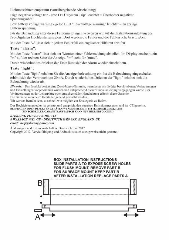
Lichtmaschinentemperatur (vorrübergehende Abschaltung)
High negative voltage trip - rote LED "System Trip" leuchtet = Überhöhter negativer Spannungsabfall
Low battery voltage warning - gelbe LED "Low voltage warning" leuchtet = zu geringe Batteriespannung
Für die Behandlung aller dieser Fehlermeldungen verweisen wir auf die Installationsanleitung des Pro-Digitalen Hochleistungsreglers. Dort werden die Fehler und die Fehlersuche beschrieben.
Mit der Taste " "̄ lässt sich in jedem Fehlerfall ein englischer Hilfstext abrufen.
Taste "alarm":
Mit der Taste "alarm" lässt sich der Warnton einer Fehlermeldung abstellen. Im Display erscheint ein "m" auf der rechten Seite der Anzeige. "m" steht für "mute".
Durch wiederhohltes drücken der Taste lässt sich der Alarm wieder einschaltetn.
Taste "light":
Mit der Taste "light" schalten Sie die Anzeigenbeleuchtung ein. Ist die Beleuchtung eingeschaltet erhöht sich der Verbrauch um 20mA. Durch wiederholtes Drücken der "light" schaltet sich die Beleuchtung wieder ab.
Wir werden bemüht sein, so schnell wie möglich ein Ersatzgerät zu liefern.
Der Hochleistungsregler ist getestet und entspricht den neuesten Emissionsgesetzen und ist CE genormt.BEI FRAGEN ODER DEFEKTEN GERÄTEN WENDEN SIE SICH BITTE IMMER DIREKT AN:
(EIN SCHNELLER GARANTIEAUSTAUSCH KANN NUR HIER ERFOLGEN!!)
STERLING POWER PRODUCTS8 WASSAGE WAY, GB - DROITWICH WR9 0NX, ENGLAND, UKemail: [email protected]
Änderungen und Irrtum vorbehalten. Droitwich, Jan 2012Copyright 2012, Vervielfältigung und Abdruck ist auch auzugsweise nicht gestattet.
Hinweis: Das Produkt besitzt eine Zwei-Jahres-Garantie, wenn keine als die hier beschriebenen Veränderungen und Einstellungen vorgenommen wurden und entsprechend dieser Einbauanleitung vorgegangen wurde. Bei Veränderungen an der Leiterplatte oder unsachgemäßer Handhabung erlischt diese Garantie.Die Garantie kann beim Hersteller geltend gemacht werden.
A
B
BOX INSTALLATION INSTRUCTIONSSLIDE PARTS A TO EXPOSE SCREW HOLESFOR FLUSH MOUNT, REMOVE PART BFOR SURFACE MOUNT KEEP PART BAFTER INSTALLATION REPLACE PARTS A