Stereo and Multiview Imaging Summary - Icarus
35
Stereo and Multiview Imaging Summary S. Papadopoulos, Prof. Ioannis Pitas Aristotle University of Thessaloniki [email protected] www.aiia.csd.auth.gr Version 2.5
Transcript of Stereo and Multiview Imaging Summary - Icarus

Stereo and Multiview
Imaging Summary
S. Papadopoulos, Prof. Ioannis Pitas
Aristotle University of Thessaloniki
www.aiia.csd.auth.gr
Version 2.5
Introduction to Stereopsis
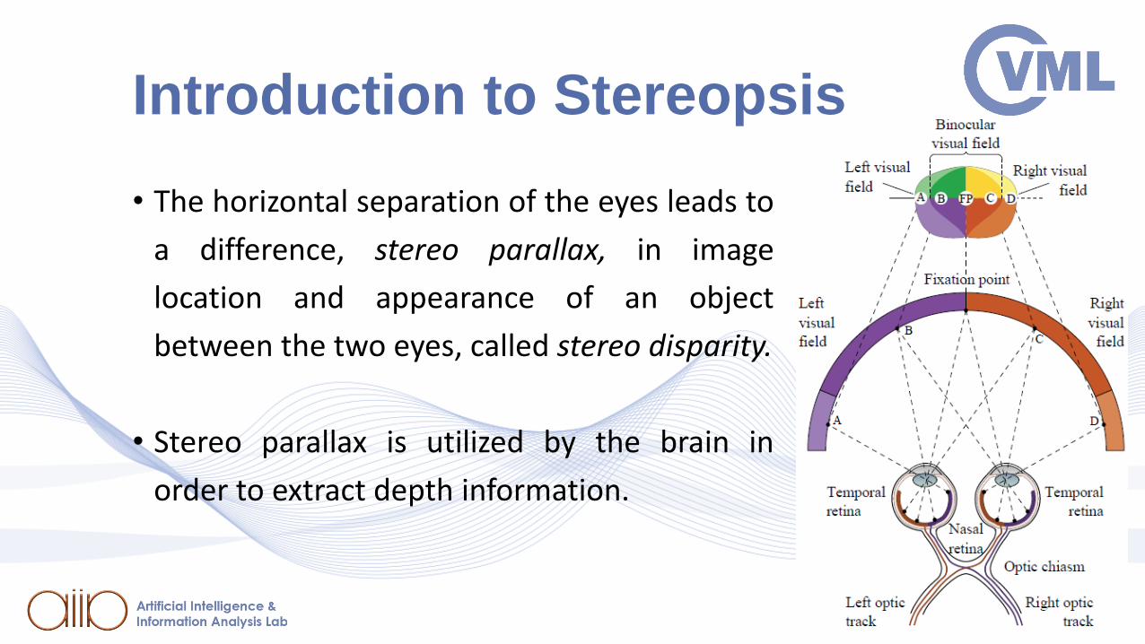
• The horizontal separation of the eyes leads to
a difference, stereo parallax, in image
location and appearance of an object
between the two eyes, called stereo disparity.
• Stereo parallax is utilized by the brain in
order to extract depth information.

Basics of Stereopsis
• Scene depth can by inferred by simultaneous acquisition of two
scene views, from slightly different world positions.
• Use of disparity maps for depth estimation.
• Stereo camera rig:
• Parallel (two cameras with parallel optical axes).
• Converging (two cameras with converging optical axes).

Basics of Stereopsis
Parallel Stereo vision Geometry
𝑇: baseline𝑓: focal length

Basics of Stereopsis
• In a parallel stereo rig, vertical disparity/parallax is zero.
• Horizontal disparity: 𝑑 = 𝑥𝑟 – 𝑥𝑙 ≤ 0.
• 𝑑 is inversely proportional to scene depth 𝑍𝑤 (by triangle
similarity):
𝑑 = −𝑓 𝑇𝑍𝑤
• Thus, 𝑑 decreases as the imaged object distance from the
camera increases.
• 𝑑 is zero for visible scene points at infinity.

Basics of Stereopsis
• A dense disparity map can beestimated from detecting pixelcorrespondences.

Epipolar Geometry
• Epipolar geometry is two-view
geometry, i.e., the geometry of
stereoscopic 3D vision.
• Property: Different 3D scene points
projecting to the same left-view 2D
point, may project to different right-
view 2D points (parallax effect).
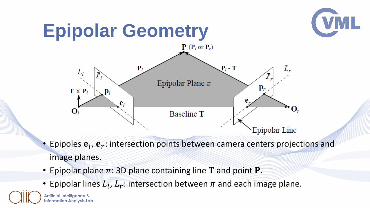
• Epipoles 𝐞𝑙, 𝐞𝑟: intersection points between camera centers projections and
image planes.
• Epipolar plane 𝜋: 3D plane containing line 𝐓 and point 𝐏.
• Epipolar lines 𝐿𝑙, 𝐿𝑟: intersection between 𝜋 and each image plane.
Epipolar Geometry

• The Essential Matrix 𝐄 compactly encodes the epipolar constraint:
𝐏𝑟𝑇𝐄𝐏𝑙 = 0
where:
𝐄 = 𝐑𝐓× =
𝑇𝑧𝑟12 − 𝑇𝑦𝑟13 −𝑇𝑧𝑟11 + 𝑇𝑥𝑟13 𝑇𝑦𝑟11 − 𝑇𝑥𝑟12𝑇𝑧𝑟22 − 𝑇𝑦𝑟23 −𝑇𝑧𝑟21 + 𝑇𝑥𝑟23 𝑇𝑦𝑟21 − 𝑇𝑥𝑟22𝑇𝑧𝑟32 − 𝑇𝑦𝑟33 −𝑇𝑧𝑟31 + 𝑇𝑥𝑟33 𝑇𝑦𝑟31 − 𝑇𝑥𝑟32
• 𝐄 is a 3 × 3 rank-deficient matrix. It is is completely determined by the
rotation and translation between the two cameras/views.
• If the WCS coincides with the coordinate system of the left or right camera, 𝐄 encodes
extrinsic camera parameters (incl. baseline 𝐓).
The Essential Matrix 𝐄
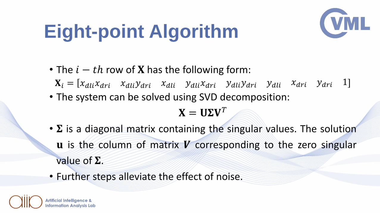
• The 𝑖 − 𝑡ℎ row of 𝐗 has the following form:𝐗𝑖 = 𝑥𝑑𝑙𝑖𝑥𝑑𝑟𝑖 𝑥𝑑𝑙𝑖𝑦𝑑𝑟𝑖 𝑥𝑑𝑙𝑖 𝑦𝑑𝑙𝑖𝑥𝑑𝑟𝑖 𝑦𝑑𝑙𝑖𝑦𝑑𝑟𝑖 𝑦𝑑𝑙𝑖 𝑥𝑑𝑟𝑖 𝑦𝑑𝑟𝑖 1
• The system can be solved using SVD decomposition:
𝐗 = 𝐔𝚺𝐕𝑇
• 𝚺 is a diagonal matrix containing the singular values. The solution
𝐮 is the column of matrix 𝑽 corresponding to the zero singular
value of 𝚺.
• Further steps alleviate the effect of noise.
Eight-point Algorithm

• Rectification is the process of rotating each of the two image
planes (left-right) around the corresponding optical centers, so
that all epipolar lines
become horizontal.
• In parallel stereo-rigs
with equal focal lengths,
the views are already
rectified.
Rectification

• Rectification simplifies the search for pixel correspondences between views:
• Search on epipolar lines becomes a search along a horizontal scan line, at the sameheight as the reference pixel.
Rectification

• The parallel, side-by-side stereo rig design tries to imitate the way
eyes are positioned on the human face
• The cameras can:
• perform horizontal shifts, thus
changing their inter-axial (baseline)
distance 𝑇,
• converge and diverge,
• change zoom and focus.
Stereo Camera Technologies
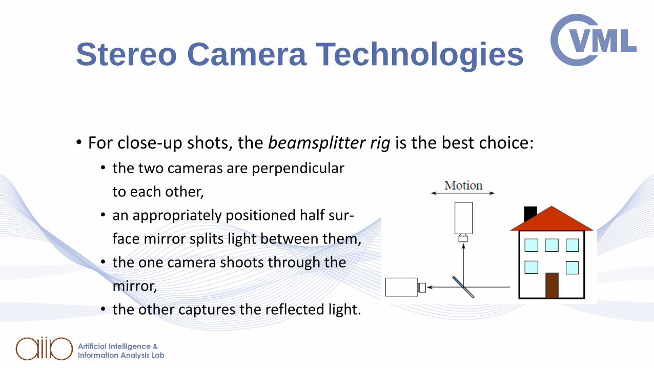
• For close-up shots, the beamsplitter rig is the best choice:
• the two cameras are perpendicular
to each other,
• an appropriately positioned half sur-
face mirror splits light between them,
• the one camera shoots through the
mirror,
• the other captures the reflected light.
Stereo Camera Technologies

• The 3D geometry of a scene can be recovered, given multiple 2D
scene views.
• The multiple views may come from different view points /
cameras:
• stereoscopic / binocular view, trinocular view, Multiview imaging
• The may come from a moving camera: Structure-from-Motion
(SfM).
• In SfM, the scene has to be static.
Feature Correspondence

Feature Correspondence

• Distance-based matching measures which can be used:
• The sum of absolute differences (SAD) or 𝐿1 norm:
𝑆𝐴𝐷 𝐩𝑙 , 𝐩𝑟 =
𝑖=−𝑁
𝑁
𝑗=−𝑀
𝑀
𝑓𝑙 𝑥𝑙 + 𝑖, 𝑦𝑙 + 𝑗 − 𝑓𝑟 𝑥𝑟 + 𝑖, 𝑦𝑟 + 𝑗
• The sum of squared differences (SSD) or 𝐿2 norm:
𝑆𝑆𝐷 𝐩𝑙 , 𝐩𝑟 =
𝑖=−𝑁
𝑁
𝑗=−𝑀
𝑀
𝑓𝑙 𝑥𝑙 + 𝑖, 𝑦𝑙 + 𝑗 − 𝑓𝑟 𝑥𝑟 + 𝑖, 𝑦𝑟 + 𝑗2
Feature Matching Algorithms

• Convolutional NN architecture for patch comparison
[ZBO2015]:
• CNN is trained to predict how well two image patches
match and use it to compute the stereo matching cost:
𝐶𝑆𝐴𝐷 𝒑, 𝑑 = σ𝒒∈𝑵𝒑|𝐼𝐿 𝒒 − 𝐼𝑅(𝒒 − 𝒅)|
• 𝐼𝐿 𝒑 and 𝐼𝑅 𝒑 are image intensities at position 𝒑 in the left and right
image
• 𝑵𝒑 is the set of locations within a fixed rectangular window centered at
𝒑
• 𝒑 and 𝒒 denote image locations
• 𝒅 is disparity 𝑑 cast to a vector: 𝒅 = (𝑑, 0).
Disparity Estimation with NNs
[ZBO2015]

• The cost is refined by cross-based cost aggregation and
semiglobal matching, followed by a left-right consistency check
to eliminate errors in the occluded regions.
• To obtain the final disparity map, subpixel enhancement is
performed, as well as a median and a bilateral filter are applied.
Disparity Estimation with NNs
[ZBO2015]
[ZBO2015]
• Three general cases of 3D point cloud reconstruction:
• Calibrated cameras: known intrinsic and extrinsic parameters –
reconstruction is a simple matter of triangulation.
• Uncalibrated cameras: some or all camera parameters are unknown –
calibration needs to take place.
• Known intrinsic parameters only: estimation of the extrinsic parameters and the
3D geometry up to an unknown scaling factor can solve the problem.
• No parameters known: 3D reconstruction only possible up to an
unknown projective transformation.
3D Reconstruction Techniques in Stereo Vision

• 𝐎𝑙 , 𝐎𝑟 : the centers of projection of the left/right camera –
origins of the coordinate systems 𝑋𝑙 , 𝑌𝑙 , 𝑍𝑙 , 𝑋𝑟 , 𝑌𝑟 , 𝑍𝑟 .
• 𝔗l, 𝔗𝑟: the virtual image planes of the left/right camera.
• 𝑇𝑐: the camera baseline - distance between the two centers of
projection.
• 𝑓: the camera focal length - distance between the center of
projection of a camera and its image plane.
• 𝐎𝑐: the center of the world coordinate system 𝑋𝑤, 𝑌𝑤 , 𝑍𝑤 -
baseline midpoint.
Parallel and Converging Camera Setups

• Transformation from left/right
camera coordinates to world
coordinates in parallel stereo-rig
setup by translation by Τ𝑇𝑐 2.
𝑋𝑤𝑌𝑤𝑍𝑤
=𝑋𝑙 −
𝑇𝑐2
𝑌𝑙𝑍𝑙
=𝑋𝑟 +
𝑇𝑐2
𝑌𝑟𝑍𝑟
Parallel and Converging Camera Setups

• Triangle similarities can be used to recover 3D world coordinates
𝐏𝑤 from left/right image plane coordinates, assuming all camera
parameters and point disparity values 𝑑𝑐 = 𝑥𝑟 − 𝑥𝑙 are known:
𝑍𝑤 = −𝑓𝑇𝑐
𝑑𝑐𝑋𝑤 = −
𝑇𝑐 𝑥𝑙+𝑥𝑟
2𝑑𝑐𝑌𝑤 = −
𝑇𝑐𝑦𝑙
𝑑𝑐= −
𝑇𝑐𝑦𝑟
𝑑𝑐
Parallel and Converging Camera Setups
• The converging camera setup produces:
• Negative camera disparities for object having 𝑍𝑤 < 𝑍𝑐, thus appearing
in front of the screen place.
• Zero camera disparities for object having 𝑍𝑤 = 𝑍𝑐, thus appearing on
the screen plane.
• Positive camera disparities for object having 𝑍𝑤 > 𝑍𝑐, thus appearing
behind the screen plane.
• Objects at infinity 𝑍𝑙 = 𝑍𝑟 = 𝑍𝑤 = ∞ have large positive
disparity.
Parallel and Converging Camera Setups

• Due to noise in camera
calibration, triangulation refine-
ment may be needed, so that the
rays emanating from the optical
centers of the cameras and
passing through its left and right
projections intersect on (or close
to) 𝐏.
General 3D reconstruction in a calibrated stereo camera system

Three-Views and the Point Transfer
• Given two image points 𝐩1, 𝐩2 on the first and second image plane,
respectively, the exact position of the corresponding point 𝐩3 on the third
image plane can be completely specified in terms of 𝐩1, 𝐩2.
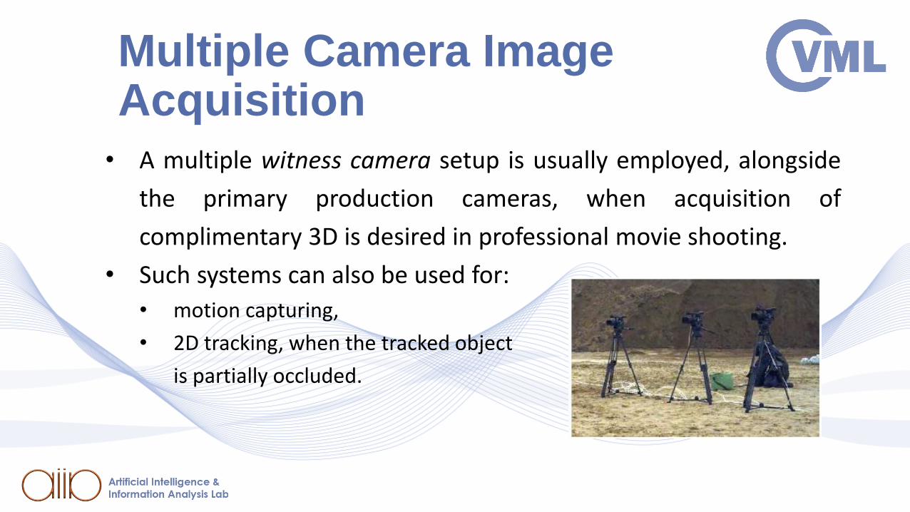
Multiple Camera Image Acquisition
• A multiple witness camera setup is usually employed, alongside
the primary production cameras, when acquisition of
complimentary 3D is desired in professional movie shooting.
• Such systems can also be used for:
• motion capturing,
• 2D tracking, when the tracked object
is partially occluded.
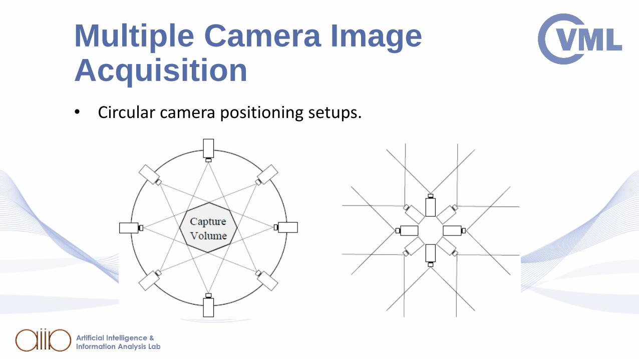
Multiple Camera Image Acquisition• Circular camera positioning setups.

Self-calibration
• Self-calibration or autocalibration: a family of camera calibration
methods using solely image information.
• Pros: flexibility, simplicity.
• Cons: lacking robustness, may fail in degenerate cases.
• Relies on epipolar and projective geometry concepts.
• Multiple views of a 3D scene are needed.

Self-calibration
• Recent self-calibration approach: stochastic optimization of a
metric that depends on the intrinsic parameters 𝐏𝐼𝑙 , 𝐏𝐼𝑟.
• Optimization algorithms employed to this end:
• particle swarm optimization,
• genetic optimization.
• Commonly used metric for minimization:
• a reformulation of the simplified Kruppa equation.
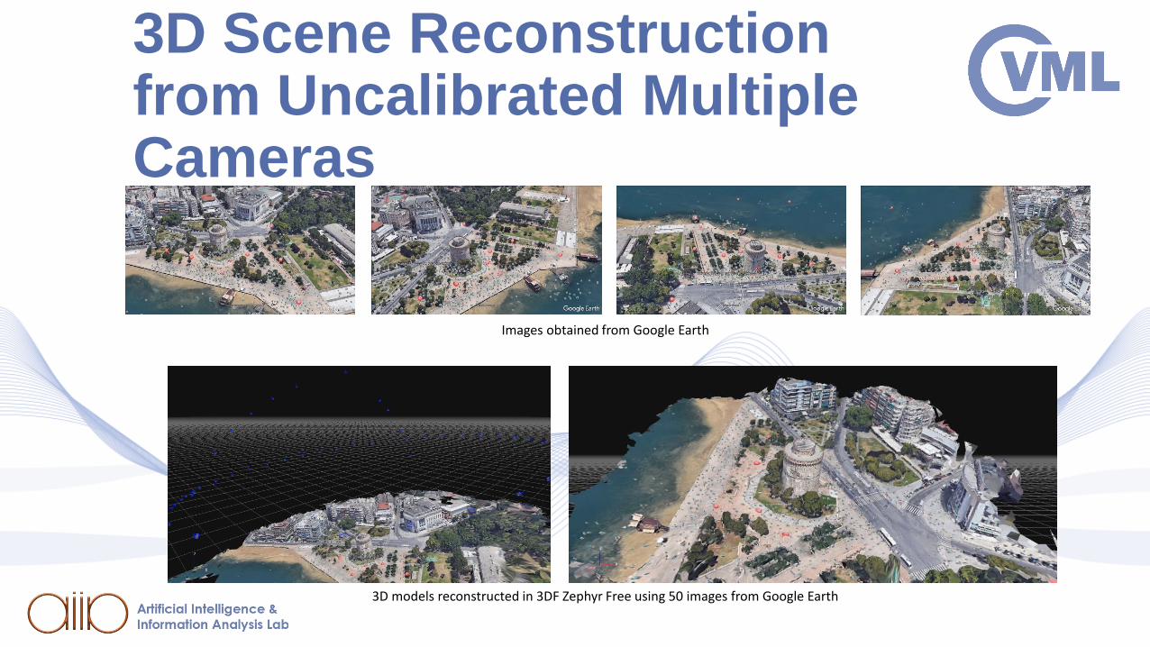
3D Scene Reconstruction from Uncalibrated Multiple Cameras
Images obtained from Google Earth
3D models reconstructed in 3DF Zephyr Free using 50 images from Google Earth

3D monument modelling:Vlatadon Monastery, Thessaloniki

3D monument modelling:Vlatadon Monastery, Thessaloniki
Bibliography[PIT2019] I. Pitas, “Computer vision”, Createspace/Amazon, in press. [SZE2011] R.Szelinski, “ Computer Vision ” , Springer 2011[HAR2003] Hartley R, Zisserman A. , “ Multiple view geometry in computer vision” .
Cambridge university press; 2003.[DAV2017] Davies, E. Roy. “Computer vision: principles, algorithms, applications,
learning ”. Academic Press, 2017[TRU1998] Trucco E, Verri A. “Introductory techniques for 3-D computer vision”, Prentice
Hall, 1998.[PIT2017] I. Pitas, “Digital video processing and analysis ” , China Machine Press, 2017
(in Chinese).[PIT2013] I. Pitas, “Digital Video and Television ” , Createspace/Amazon, 2013.[PIT2000] I. Pitas, Digital Image Processing Algorithms and Applications, J. Wiley, 2000. [NIK2000] N. Nikolaidis and I. Pitas, 3D Image Processing Algorithms, J. Wiley, 2000.
62


![arXiv:1604.08256v1 [cs.CV] 27 Apr 2016 · Ricardo Fabbri Benjamin B. Kimia ... aiming at stereo correspondence, camera estimation (including calibration, pose, and multiview epipolar](https://static.fdocuments.us/doc/165x107/5c83bdc809d3f290718bf989/arxiv160408256v1-cscv-27-apr-2016-ricardo-fabbri-benjamin-b-kimia-.jpg)