Steps to Install Windows XP
32
Steps to Install Windows XP Welcome to setup screen. To start the Windows XP installation process and install the Windows XP operating system on the computer just press on Enter key. To exit the installation process press F3 key. Windows XP Professional End User licensing agreement, use Page Down key to read trough the license agreement an press F8 key to agree.
Transcript of Steps to Install Windows XP

8/8/2019 Steps to Install Windows XP
http://slidepdf.com/reader/full/steps-to-install-windows-xp 1/32
Steps to Install Windows XP
Welcome to setup screen. To start the Windows XP installation process and install the
Windows XP operating system on the computer just press on Enter key. To exit the
installation process press F3 key.
Windows XP Professional End User licensing agreement, use Page Down key to read
trough the license agreement an press F8 key to agree.

8/8/2019 Steps to Install Windows XP
http://slidepdf.com/reader/full/steps-to-install-windows-xp 2/32
Setup then display the list of existing partitions and unpartitioned space on the system.
Press Enter key to setup Windows XP on selected item, or press C key if you want to
create partition on the disk.
The Setup display your system disk available space. To create partition, enter the amount
of disk space for the partition size to be create. Then press Enter key.

8/8/2019 Steps to Install Windows XP
http://slidepdf.com/reader/full/steps-to-install-windows-xp 3/32
Select the partition where you want the Windows XP install and then press Enter key.
Choose and select to format the partition using the NTFS file system. Then press Enter
key to continue with the setup process.

8/8/2019 Steps to Install Windows XP
http://slidepdf.com/reader/full/steps-to-install-windows-xp 4/32
The setup then formatting the partition selected with the NTFS file system. The progress
bar show the formatting process process. Wait until the process finish, this process may
take several minutes depends on the disk size.
The setup process then examines your system disk drives. This process may take several
minutes depending on the size of disks.

8/8/2019 Steps to Install Windows XP
http://slidepdf.com/reader/full/steps-to-install-windows-xp 5/32
Windows XP setup on progress and copying files to disk, please wait this process may
take several minutes to complete.
Portion of Windows XP setup completed successfully. The setup process reboot your computer automatically or you can press Enter key to restart the computer.

8/8/2019 Steps to Install Windows XP
http://slidepdf.com/reader/full/steps-to-install-windows-xp 6/32
8/8/2019 Steps to Install Windows XP
http://slidepdf.com/reader/full/steps-to-install-windows-xp 7/32
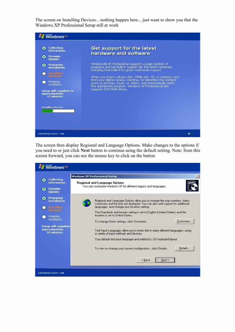
The screen on Installing Devices... nothing happen here... just want to show you that the
Windows XP Professional Setup still at work
The screen then display Regional and Language Options. Make changes to the options if
you need to or just click Next button to continue using the default setting. Note: from this
screen forward, you can use the mouse key to click on the button
8/8/2019 Steps to Install Windows XP
http://slidepdf.com/reader/full/steps-to-install-windows-xp 8/32
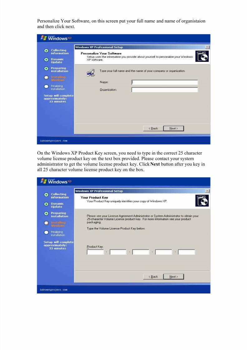
Personalize Your Software, on this screen put your full name and name of organistaion
and then click next.
On the Windows XP Product Key screen, you need to type in the correct 25 character
volume license product key on the text box provided. Please contact your system
administrator to get the volume license product key. Click Next button after you key inall 25 character volume license product key on the box.

8/8/2019 Steps to Install Windows XP
http://slidepdf.com/reader/full/steps-to-install-windows-xp 9/32
On this Computer Name and Administrator Password screen, you need to provide the
Computer name, Administrator password and you need to re type password in the
Confirm password box. Just remember or write down the administrator password becauseyou may need to log in as administrator one day to gain full access on the system. Click
Next button to proceed.
On the Date and Time Settings screen, you can set the correct date and time for your
Windows XP Professional system, then choose from the drop down list the correct Time
Zone setting for the system time. Click Next button after finish with the configurationsetting.

8/8/2019 Steps to Install Windows XP
http://slidepdf.com/reader/full/steps-to-install-windows-xp 10/32
Installing Network Screen, and the screen display the status bar show that the estimate
time to complete the installation process is down to 31 minutes.
The Networking Setting screen. On the Networking Setting screen you can configure thesystem networking components manually or you can leave the radio button on 'Typical
Settings' to accept the default configuration. Click Next button to proceed.

8/8/2019 Steps to Install Windows XP
http://slidepdf.com/reader/full/steps-to-install-windows-xp 11/32
The Workgroup or Computer Domain screen, enter the workgroup name if your
computer belong to the existing workgroup or leave the default WORKGROUP and If
your computer is a member of the domain on the network, click the radio button on 'Yes,make this computer a member of the following domain:' and then type in the domain
name in the box provided. Click Next button to proceed.
Windows XP then start copying files to the system hard disk, sit back and read all theusual advert info on the screen or better yet you can go and make your self a nice cup of
coffee and return back to your computer after half an hour

8/8/2019 Steps to Install Windows XP
http://slidepdf.com/reader/full/steps-to-install-windows-xp 12/32
The Windows XP Setup screen display that the Setup removing temporary files and
status bar show that the setup process will complete in approximately in 1 minute.
Reboot Windows XP screenshot.

8/8/2019 Steps to Install Windows XP
http://slidepdf.com/reader/full/steps-to-install-windows-xp 13/32
The process of starting Windows XP screen shot.
The welcome screen to setting up your computer. Click Next button to continue.

8/8/2019 Steps to Install Windows XP
http://slidepdf.com/reader/full/steps-to-install-windows-xp 14/32
The setting of automatic updates your Windows XP. Click on the radio button Help
protect my PC by turning on Automatic Updates now to make sure your Windows XP
system check the updates (this include hot fix (patch, security, critical updates) andservice packs) from Microsoft Windows Updates site and automatically install the
updates. If you want to Updates your system manually just click the radio button on Not
right now. Click Next button to proceed.
Windows XP setup then display the screen of Checking your Internet connectivity. This
process may take few moments, because the setup check your computer to see if the
computer already connected to the internet or not.

8/8/2019 Steps to Install Windows XP
http://slidepdf.com/reader/full/steps-to-install-windows-xp 15/32
On this screen you can choose the configuration of your connection to the internet, click
the radio button on Local area network (LAN) to setup the configuration of you network
card. Click Next button to proceed.
The Setting up a high speed connection (or LAN) screen. On this screen you can setup
the setting of your network ip address. Obtain the ip address, subnet mask, gateway and
DNS from your network administrator and put in the box, or if your network using the
DHCP to get the ip setting and DNS setting just click the checkbox provided. Click Next
button to proceed.

8/8/2019 Steps to Install Windows XP
http://slidepdf.com/reader/full/steps-to-install-windows-xp 16/32
Register Windows XP screen. There is two radio button on this screen, click on the Yes,
I'd like to register with Microsoft now to start registering your Windows XP now or
if you want to finish with the installation and setup process and you want to register later click radio button on No, not this time. Click Next button to proceed.
On the user account screen, type in the user name that who will use the computer.

8/8/2019 Steps to Install Windows XP
http://slidepdf.com/reader/full/steps-to-install-windows-xp 17/32
Thank you and congratulation screen. Click Finish button to finish the Windows XP
setup configuration.

8/8/2019 Steps to Install Windows XP
http://slidepdf.com/reader/full/steps-to-install-windows-xp 18/32
Functions of Operating System
An operating system is a software component that acts as the core of a computer system.It performs various functions and is essentially the interface that connects your computer
and its supported components. In this article, we will discuss the basic functions of the
operating system, along with security concerns for the most popular types. Also learnmore about driver updates.
Basic Operation
Drivers play a major role in the operating system. A driver is a program designed to
comprehend the functions of a particular device installed on the system. A driver enables
the operation of numerous devices, including your mouse, keyboard printer, video cardand CD-ROM drive by translating commands from the operating system or the user into
commands understood by the associated component. It also translates responses from the
component back to the operating system, software application or user.
The operating system performs other functions with system utilities that monitor
performance, debug errors and maintain the system. It also includes a set of libraries
often used by applications to perform tasks to enable direct interaction with system
components. These common functions run seamlessly and are transparent to most users.
Security Concerns
The fact that an operating system is computer software makes it prone to error just as any
human creation. Programmers make mistakes, and inefficient code is often implemented
into programs even after testing. Some developers perform more thorough testing andgenerally produce more efficient software. Therefore, some operating systems and more
error prone while others are more secure.
Here are some common security issues that pose a threat to all operating systems:
Instabilities and Crashes - Both of these instances may be the result of software bugs in
the operating system. Bugs in software applications on the computer may also cause problems, such as preventing the system from communicating with hardware devices.
They can even cause the system to become unstable or crash. A system crash consists of
freezing and becoming unresponsive to point where the machine needs to be rebooted.These issues vary depending on the type of operating system.
Flaws - Software bugs will not only make a system unstable, but also leave it wide opento unauthorized users. Once these vulnerabilities are discovered, attackers can exploit
them and gain access to your system. From there, they can install malware, launch attackson other machines or even take complete control of your system. Software developers
usually distribute security patches rather quickly to update the operating system and fix
the vulnerabilities.

8/8/2019 Steps to Install Windows XP
http://slidepdf.com/reader/full/steps-to-install-windows-xp 19/32
Introduction to Networks
A computer network is a connection of as few as two computers or devices with a means
of connecting media for enabling the two computers or devices to communicate andunderstand each other.
Using Computer Networks, it allows more than one user to use the same program at the
same time and provide the means for communication between different computer
systems.
Networks can be useful in several ways, examples are- Sharing resources,
Sharing information, Use of electronic mail and Protecting information.
Computer networks fall into three categories:
LAN- Local Area Network WAN-Wide Area Network
MAN- Metropolitan Area Network
We discuss on the OSI model that allows communication between computers easy, it
divides the network seven layers that are physical, data link, network, transport, session, presentation and the application layer.
The OSI layers communicate directly with the receiving layer in the receiving host. Data
that passes from layers to layers is called protocol data units (PDU) in each layer data that
are transmitted are referred to in a different way. e.g. Bits, Frames, Packets and Segment.
Networks can be constructed with Internetworking devices.
Repeater- extends the physical length of a cable type in making a connection.
Bridges- it passes data frames between network using MAC addresses.
Hubs- it allows nodes to be interconnected.Switches- it allows communication at the same time between two or more nodes.
Routers- packets are passed between connected networks.
A brief explanation of the above points can be seen in the next few pages.
Types of Network Protocol
TCP/IP
TCP and IP were developed by a Department of Defense (DOD) research project toconnect a number different networks designed by different vendors into a network of
networks (the "Internet"). It was initially successful because it delivered a few basic
services that everyone needs (file transfer, electronic mail, remote logon) across a verylarge number of client and server systems. Several computers in a small department can
use TCP/IP (along with other protocols) on a single LAN. The IP component provides
routing from the department to the enterprise network, then to regional networks, andfinally to the global Internet. On the battlefield a communications network will sustain
damage, so the DOD designed TCP/IP to be robust and automatically recover from any
node or phone line failure. This design allows the construction of very large networks

8/8/2019 Steps to Install Windows XP
http://slidepdf.com/reader/full/steps-to-install-windows-xp 20/32
with less central management. However, because of the automatic recovery, network
problems can go undiagnosed and uncorrected for long periods of time.
As with all other communications protocol, TCP/IP is composed of layers:
• IP - is responsible for moving packet of data from node to node. IP forwards each packet based on a four byte destination address (the IP number). The Internet
authorities assign ranges of numbers to different organizations. The organizationsassign groups of their numbers to departments. IP operates on gateway machinesthat move data from department to organization to region and then around the
world.
• TCP - is responsible for verifying the correct delivery of data from client to
server. Data can be lost in the intermediate network. TCP adds support to detecterrors or lost data and to trigger retransmission until the data is correctly and
completely received.
• Sockets - is a name given to the package of subroutines that provide access toTCP/IP on most systems.
Network of Lowest Bidders
The Army puts out a bid on a computer and DEC wins the bid. The Air Force puts out a
bid and IBM wins. The Navy bid is won by Unisys. Then the President decides to invadeGrenada and the armed forces discover that their computers cannot talk to each other.
The DOD must build a "network" out of systems each of which, by law, was delivered by
the lowest bidder on a single contract.
The Internet Protocol was developed to create a Network of Networks (the "Internet").Individual machines are first connected to a LAN (Ethernet or Token Ring). TCP/IP
shares the LAN with other uses (a Novell file server, Windows for Workgroups peer systems). One device provides the TCP/IP connection between the LAN and the rest of
the world.
To insure that all types of systems from all vendors can communicate, TCP/IP is
absolutely standardized on the LAN. However, larger networks based on long distancesand phone lines are more volatile. In the US, many large corporations would wish to

8/8/2019 Steps to Install Windows XP
http://slidepdf.com/reader/full/steps-to-install-windows-xp 21/32
reuse large internal networks based on IBM's SNA. In Europe, the national phone
companies traditionally standardize on X.25. However, the sudden explosion of high
speed microprocessors, fiber optics, and digital phone systems has created a burst of newoptions: ISDN, frame relay, FDDI, Asynchronous Transfer Mode (ATM). New
technologies arise and become obsolete within a few years. With cable TV and phone
companies competing to build the National Information Superhighway, no singlestandard can govern citywide, nationwide, or worldwide communications.
The original design of TCP/IP as a Network of Networks fits nicely within the current
technological uncertainty. TCP/IP data can be sent across a LAN, or it can be carried
within an internal corporate SNA network, or it can piggyback on the cable TV service.Furthermore, machines connected to any of these networks can communicate to any other
network through gateways supplied by the network vendor.
Addresses
Each technology has its own convention for transmitting messages between two
machines within the same network. On a LAN, messages are sent between machines by
supplying the six byte unique identifier (the "MAC" address). In an SNA network, everymachine has Logical Units with their own network address. DECNET, Appletalk, and
Novell IPX all have a scheme for assigning numbers to each local network and to eachworkstation attached to the network.
On top of these local or vendor specific network addresses, TCP/IP assigns a unique
number to every workstation in the world. This "IP number" is a four byte value that, by
convention, is expressed by converting each byte into a decimal number (0 to 255) andseparating the bytes with a period. For example, the PC Lube and Tune server is
130.132.59.234.
An organization begins by sending electronic mail to [email protected] assignment of a network number. It is still possible for almost anyone to getassignment of a number for a small "Class C" network in which the first three bytes
identify the network and the last byte identifies the individual computer. The author
followed this procedure and was assigned the numbers 192.35.91.* for a network of computers at his house. Larger organizations can get a "Class B" network where the first
two bytes identify the network and the last two bytes identify each of up to 64 thousand
individual workstations. Yale's Class B network is 130.132, so all computers with IPaddress 130.132.*.* are connected through Yale.
The organization then connects to the Internet through one of a dozen regional or
specialized network suppliers. The network vendor is given the subscriber network number and adds it to the routing configuration in its own machines and those of theother major network suppliers.
Subnets
Although the individual subscribers do not need to tabulate network numbers or provide
explicit routing, it is convenient for most Class B networks to be internally managed as amuch smaller and simpler version of the larger network organizations. It is common to

8/8/2019 Steps to Install Windows XP
http://slidepdf.com/reader/full/steps-to-install-windows-xp 22/32
subdivide the two bytes available for internal assignment into a one byte department
number and a one byte workstation ID.
The enterprise network is built using commercially available TCP/IP router boxes. Eachrouter has small tables with 255 entries to translate the one byte department number into
selection of a destination Ethernet connected to one of the routers. Messages to the PC
Lube and Tune server (130.132.59.234) are sent through the national and New England
regional networks based on the 130.132 part of the number. Arriving at Yale, the 59department ID selects an Ethernet connector in the C& IS building. The 234 selects a
particular workstation on that LAN. The Yale network must be updated as new Ethernets
and departments are added, but it is not effected by changes outside the university or themovement of machines within the department.
A Uncertain Path
Every time a message arrives at an IP router, it makes an individual decision about where
to send it next. There is concept of a session with a preselected path for all traffic.Consider a company with facilities in New York, Los Angeles, Chicago and Atlanta. It
could build a network from four phone lines forming a loop (NY to Chicago to LA to
Atlanta to NY). A message arriving at the NY router could go to LA via either Chicago
or Atlanta. The reply could come back the other way.
How does the router make a decision between routes? There is no correct answer. Traffic
could be routed by the "clockwise" algorithm (go NY to Atlanta, LA to Chicago). The
routers could alternate, sending one message to Atlanta and the next to Chicago. Moresophisticated routing measures traffic patterns and sends data through the least busy link.
If one phone line in this network breaks down, traffic can still reach its destination
through a roundabout path. After losing the NY to Chicago line, data can be sent NY to
Atlanta to LA to Chicago. This provides continued service though with degraded performance. This kind of recovery is the primary design feature of IP. The loss of the
line is immediately detected by the routers in NY and Chicago, but somehow this
information must be sent to the other nodes. Otherwise, LA could continue to send NY
messages through Chicago, where they arrive at a "dead end." Each network adopts some

8/8/2019 Steps to Install Windows XP
http://slidepdf.com/reader/full/steps-to-install-windows-xp 23/32
Router Protocol which periodically updates the routing tables throughout the network
with information about changes in route status.
If the size of the network grows, then the complexity of the routing updates will increase
as will the cost of transmitting them. Building a single network that covers the entire USwould be unreasonably complicated. Fortunately, the Internet is designed as a Network of
Networks. This means that loops and redundancy are built into each regional carrier. The
regional network handles its own problems and reroutes messages internally. Its Router Protocol updates the tables in its own routers, but no routing updates need to propagate
from a regional carrier to the NSF spine or to the other regions (unless, of course, a
subscriber switches permanently from one region to another).
Undiagnosed Problems
IBM designs its SNA networks to be centrally managed. If any error occurs, it is reported
to the network authorities. By design, any error is a problem that should be corrected or
repaired. IP networks, however, were designed to be robust. In battlefield conditions, the
loss of a node or line is a normal circumstance. Casualties can be sorted out later on, but
the network must stay up. So IP networks are robust. They automatically (and silently)reconfigure themselves when something goes wrong. If there is enough redundancy built
into the system, then communication is maintained.
In 1975 when SNA was designed, such redundancy would be prohibitively expensive, or
it might have been argued that only the Defense Department could afford it. Today,
however, simple routers cost no more than a PC. However, the TCP/IP design that,
"Errors are normal and can be largely ignored," produces problems of its own.
Data traffic is frequently organized around "hubs," much like airline traffic. One could
imagine an IP router in Atlanta routing messages for smaller cities throughout the
Southeast. The problem is that data arrives without a reservation. Airline companiesexperience the problem around major events, like the Super Bowl. Just before the game,everyone wants to fly into the city. After the game, everyone wants to fly out. Imbalance
occurs on the network when something new gets advertised. Adam Curry announced the
server at "mtv.com" and his regional carrier was swamped with traffic the next day. The problem is that messages come in from the entire world over high speed lines, but they go
out to mtv.com over what was then a slow speed phone line.
Occasionally a snow storm cancels flights and airports fill up with stranded passengers.
Many go off to hotels in town. When data arrives at a congested router, there is no placeto send the overflow. Excess packets are simply discarded. It becomes the responsibility
of the sender to retry the data a few seconds later and to persist until it finally getsthrough. This recovery is provided by the TCP component of the Internet protocol.
TCP was designed to recover from node or line failures where the network propagatesrouting table changes to all router nodes. Since the update takes some time, TCP is slow
to initiate recovery. The TCP algorithms are not tuned to optimally handle packet loss
due to traffic congestion. Instead, the traditional Internet response to traffic problems has been to increase the speed of lines and equipment in order to say ahead of growth in
demand.

8/8/2019 Steps to Install Windows XP
http://slidepdf.com/reader/full/steps-to-install-windows-xp 24/32
TCP treats the data as a stream of bytes. It logically assigns a sequence number to each
byte. The TCP packet has a header that says, in effect, "This packet starts with byte
379642 and contains 200 bytes of data." The receiver can detect missing or incorrectlysequenced packets. TCP acknowledges data that has been received and retransmits data
that has been lost. The TCP design means that error recovery is done end-to-end between
the Client and Server machine. There is no formal standard for tracking problems in themiddle of the network, though each network has adopted some ad hoc tools.
File Transfer Protocol(FTP)
File Transfer Protocol (FTP) is a standard network protocol used to copy a file from
one host to another over a TCP/IP-based network, such as the Internet. FTP is built on aclient-server architecture and utilizes separate control and data connections between the
client and server. FTP users may authenticate themselves using a clear-text sign-in
protocol but can connect anonymously if the server is configured to allow it.
The first FTP client applications were interactive command-line tools, implementingstandard commands and syntax. Graphical user interface clients have since been
developed for many of the popular desktop operating systems in use today.
The protocol is specified in RFC 959, which is summarized below.
A client makes a TCP connection to the server's port 21. This connection, called thecontrol connection, remains open for the duration of the session, with a second
connection, called the data connection, opened by the server from its port 20 to a client
port (specified in the negotiation dialog) as required to transfer file data. The control
connection is used for session administration (i.e., commands, identification, passwords)exchanged between the client and server using a telnet-like protocol. For example "RETR
filename" would transfer the specified file from the server to the client. Due to this two-
port structure, FTP is considered an out-of-band , as opposed to an in-band protocol suchas HTTP.
The server responds on the control connection with three digit status codes in ASCII with
an optional text message, for example "200" (or "200 OK.") means that the last command
was successful. The numbers represent the code number and the optional text representexplanations (i.e., <OK>) or needed parameters (i.e., <Need account for storing file>). A
file transfer in progress over the data connection can be aborted using an interrupt
message sent over the control connection.
FTP can be run in active or passive mode, which determine how the data connection is
established. In active mode, the client sends the server the IP address and port number onwhich the client will listen, and the server initiates the TCP connection. In situations
where the client is behind a firewall and unable to accept incoming TCP connections, passive mode may be used. In this mode the client sends a PASV command to the server
and receives an IP address and port number in return. The client uses these to open the
data connection to the server. Both modes were updated in September 1998 to addsupport for IPv6. Other changes were made to passive mode at that time, making it
extended passive mode.

8/8/2019 Steps to Install Windows XP
http://slidepdf.com/reader/full/steps-to-install-windows-xp 25/32
While transferring data over the network, four data representations can be used:
• ASCII mode: used for text. Data is converted, if needed, from the sending host's
character representation to "8-bit ASCII" before transmission, and (again, if
necessary) to the receiving host's character representation. As a consequence, thismode is inappropriate for files that contain data other than plain text.
• Image mode (commonly called Binary mode): the sending machine sends each
file byte for byte, and the recipient stores the bytestream as it receives it. (Imagemode support has been recommended for all implementations of FTP).
• EBCDIC mode: use for plain text between hosts using the EBCDIC character set.
This mode is otherwise like ASCII mode.
• Local mode: Allows two computers with identical setups to send data in a
proprietary format without the need to convert it to ASCII
For text files, different format control and record structure options are provided. These
features were designed to facilitate files containing Telnet or ASA formatting.
Data transfer can be done in any of three modes:
• Stream mode: Data is sent as a continuous stream, relieving FTP from doing any
processing. Rather, all processing is left up to TCP. No End-of-file indicator is
needed, unless the data is divided into records.
• Block mode: FTP breaks the data into several blocks (block header, byte count,
and data field) and then passes it on to TCP.
• Compressed mode: Data is compressed using a single algorithm (usually Run-
length encoding).
Security
FTP was not designed to be a secure protocol—especially by today's standards—and hasmany security weaknesses. In May 1999, the authors of RFC 2577 enumerated the
following flaws:
• Bounce Attacks• Spoof Attacks
• Brute Force Attacks
• Packet Capture (Sniffing)
• Username Protection
• Port Stealing
FTP was not designed to encrypt its traffic; all transmissions are in clear text, and user names, passwords, commands and data can be easily read by anyone able to perform packet capture (sniffing) on the network. This problem is common to many Internet
Protocol specifications (such as SMTP, Telnet, POP and IMAP) designed prior to the
creation of encryption mechanisms such as TLS or SSL. A common solution to this problem is use of the "secure", TLS-protected versions of the insecure protocols (e.g.
FTPS for FTP, TelnetS for Telnet, etc.) or selection of a different, more secure protocol
that can handle the job, such as the SFTP/SCP tools included with most implementationsof the Secure Shell protocol.

8/8/2019 Steps to Install Windows XP
http://slidepdf.com/reader/full/steps-to-install-windows-xp 26/32
Anonymous FTP
A host that provides an FTP service may additionally provide anonymous FTP access.
Users typically log into the service with an 'anonymous' account when prompted for user
name. Although users are commonly asked to send their email address in lieu of a password, no verification is actually performed on the supplied data.
Remote FTP or FTPmail
Where FTP access is restricted, a remote FTP (or FTPmail) service can be used to
circumvent the problem. An e-mail containing the FTP commands to be performed is sentto a remote FTP server, which is a mail server that parses the incoming e-mail, executes
the FTP commands, and sends back an e-mail with any downloaded files as an
attachment. Obviously this is less flexible than an FTP client, as it is not possible to viewdirectories interactively or to modify commands, and there can also be problems with
large file attachments in the response not getting through mail servers. The service was
used when some users' only internet access was via email through gateways such as a
BBS or online service. As most internet users these days have ready access to FTP, this
procedure is no longer in everyday use.
TELNET
Telnet is a network protocol used on the Internet or local area networks to provide a bidirectional interactive text-oriented communications facility using a virtual terminal
connection. User data is interspersed in-band with Telnet control information in an 8-bit
byte oriented data connection over the Transmission Control Protocol (TCP).
Telnet was developed in 1969 beginning with RFC 15,extended in RFC 854, andstandardized as Internet Engineering Task Force (IETF) Internet Standard STD 8, one of
the first Internet standards.
Historically, Telnet provided access to a command-line interface (usually, of an operating
system) on a remote host. Most network equipment and operating systems with a TCP/IPstack support a Telnet service for remote configuration (including systems based on
Windows NT). Because of security issues with Telnet, its use for this purpose has waned
in favor of SSH.
The term telnet may also refer to the software that implements the client part of the protocol. Telnet client applications are available for virtually all computer platforms.
Telnet is also used as a verb. To telnet means to establish a connection with the Telnet
protocol, either with command line client or with a programmatic interface. For example,a common directive might be: "To change your password, telnet to the server, login and
run the passwd command." Most often, a user will be telnetting to a Unix-like server
system or a network device (such as a router) and obtain a login prompt to a command
line text interface or a character-based full-screen manager.
8/8/2019 Steps to Install Windows XP
http://slidepdf.com/reader/full/steps-to-install-windows-xp 27/32
Security
When Telnet was initially developed in 1969, most users of networked computers were in
the computer departments of academic institutions, or at large private and governmentresearch facilities. In this environment, security was not nearly as much of a concern as it
became after the bandwidth explosion of the 1990s. The rise in the number of people withaccess to the Internet, and by extension, the number of people attempting to hack other people's servers made encrypted alternatives much more of a necessity.
Experts in computer security, such as SANS Institute, recommend that the use of Telnet
for remote logins should be discontinued under all normal circumstances, for the
following reasons:
• Telnet, by default, does not encrypt any data sent over the connection (including
passwords), and so it is often practical to eavesdrop on the communications and
use the password later for malicious purposes; anybody who has access to a
router, switch, hub or gateway located on the network between the two hostswhere Telnet is being used can intercept the packets passing by and obtain login
and password information (and whatever else is typed) with any of several
common utilities like tcpdump and Wireshark.
• Most implementations of Telnet have no authentication that would ensure
communication is carried out between the two desired hosts and not intercepted in
the middle.
• Commonly used Telnet daemons have several vulnerabilities discovered over the
years.
These security-related shortcomings have seen the usage of the Telnet protocol drop
rapidly, especially on the public Internet, in favor of the Secure Shell (SSH) protocol,first released in 1995. SSH provides much of the functionality of telnet, with the addition
of strong encryption to prevent sensitive data such as passwords from being intercepted,
and public key authentication, to ensure that the remote computer is actually who itclaims to be. As has happened with other early Internet protocols, extensions to the
Telnet protocol provide Transport Layer Security (TLS) security and Simple
Authentication and Security Layer (SASL) authentication that address the above issues.
However, most Telnet implementations do not support these extensions; and there has been relatively little interest in implementing these as SSH is adequate for most purposes.
The main advantage of TLS-Telnet would be the ability to use certificate-authority signed
server certificates to authenticate a server host to a client that does not yet have the server
key stored. In SSH, there is a weakness in that the user must trust the first session to ahost when it has not yet acquired the server key.
Telnet 5250
IBM 5250 or 3270 workstation emulation is supported via custom telnet clients,TN5250/TN3270, and IBM servers. Clients and servers designed to pass IBM 5250 data
streams over Telnet generally do support SSL encryption, as SSH does not include 5250
emulation. Under OS/400, port 992 is the default port for secured telnet.

8/8/2019 Steps to Install Windows XP
http://slidepdf.com/reader/full/steps-to-install-windows-xp 28/32
Telnet data
All data octets except \377 are transmitted over the TCP transport as is. Therefore, a
Telnet client application may also be used to establish an interactive raw TCP session,and it is commonly believed that such session which does not use the IAC (\377
character, or 255 in decimal) is functionally identical. This is not the case, however, because there are other network virtual terminal (NVT) rules, such as the requirement for a bare carriage return character (CR, ASCII 13) to be followed by a NULL (ASCII 0)
character, that distinguish the telnet protocol from raw TCP sessions. On the other hand,
many systems now possess true raw TCP clients, such as netcat or socat on UNIX andPuTTY on Windows, which also can be used to manually "talk" to other services without
specialized client software. Nevertheless, Telnet is still sometimes used in debugging
network services such as SMTP, IRC, HTTP, FTP or POP3 servers, to issue commandsto a server and examine the responses, but of all these protocols only FTP really uses
Telnet data format.
Another difference of Telnet from a raw TCP session is that Telnet is not 8-bit clean bydefault. 8-bit mode may be negotiated, but high-bit-set octets may be garbled until thismode was requested, and it obviously will not be requested in non-Telnet connection.
The 8-bit mode (so named binary option) is intended to transmit binary data, not
characters though. The standard suggests the interpretation of codes \000–\176 as ASCII,
but does not offer any meaning for high-bit-set data octets. There was an attempt tointroduce a switchable character encoding support like HTTP has, but nothing is known
about its actual software support.
Types of Internet Connections
As technology grows, so does our need for bigger, better and faster Internet connections.Over the years, the way content is presented via the Web has changed drastically. Ten
years ago being able to center bold, colored text was something to admire, while today
Flash, animations, online gaming, streaming video, database-driven Web sites, e-commerce and virtual offices — to name but a few — are becoming standards. The need
for speed has changed the options available to consumers and businesses alike in terms of
how and how fast we can connect to the Internet.
While technology changes at a rapid pace, so do Internet connections. The connectionspeeds listed below represent a snapshot of general average to maximum speeds at the
time of publication. This is no doubt will change over time and Internet connectionspeeds also vary between Internet Service Providers (ISP).
Analog (up to 56k)
Also called dial-up access, it is both economical and slow. Using a modem connected to
your PC, users connect to the Internet when the computer dials a phone number (which is
provided by your ISP) and connects to the network. Dial-up is an analog connection because data is sent over an analog, public telephone network. The modem converts

8/8/2019 Steps to Install Windows XP
http://slidepdf.com/reader/full/steps-to-install-windows-xp 29/32
received analog data to digital and vise versa. Because dial-up access uses normal
telephone lines the quality of the connection is not always good and data rates are limited.
Typical Dial-up connection speeds range from 2400 bps to 56 Kbps.
ISDN
Integrated services digital network (ISDN) is an international communications standard
for sending voice, video, and data over digital telephone lines or normal telephone wires.
• Typical ISDN speeds range from 64 Kbps to 128 Kbps.
B-ISDN
Broadband ISDN is similar in function to ISDN but it transfers data over fiber optictelephone lines, not normal telephone wires. SONET is the physical transport backbone
of B-ISDN. Broadband ISDN has not been widely implemented.
DSL
DSL is also called an always on connection because it uses existing 2-wire copper
telephone line connected to the premise and will not tie up your phone as a dial-upconnection does. There is no need to dial-in to your ISP as DSL is always on. The two
main categories of DSL for home subscribers are called ADSL and SDSL.
ADSL
ADSL is the most commonly deployed types of DSL in North America. Short for
asymmetric digital subscriber line ADSL supports data rates of from 1.5 to 9 Mbps whenreceiving data (known as the downstream rate) and from 16 to 640 Kbps when sending
data (known as the upstream rate). ADSL requires a special ADSL modem.
ADSL+2
ADSL+2 A is an extension to ADSL broadband technology that provides subscriberswith significantly faster download speeds when compared to traditional ADSLconnections. ADSL+2 works in the same fashion as ADSL a special filter is installed on a
subscriber's telephone line to split existing copper telephone lines (POTS) between
regular telephone (voice) and ADSL+2. ADSL2+ service is most commonly offered inhighly-populated metropolitan areas and subscribers must be in close geographical
locations to the provider's central office to receive ADSL2+ service.
SDSL
SDSL is still more common in Europe. Short for symmetric digital subscriber line, a
technology that allows more data to be sent over existing copper telephone lines (POTS).
SDSL supports data rates up to 3 Mbps. SDSL works by sending digital pulses in thehigh-frequency area of telephone wires and can not operate simultaneously with voice
connections over the same wires. SDSL requires a special SDSL modem. SDSL is calledsymmetric because it supports the same data rates for upstream and downstream traffic.
VDSL
Very High DSL (VDSL) is a DSL technology that offers fast data rates over relatively
short distances — the shorter the distance, the faster the connection rate.

8/8/2019 Steps to Install Windows XP
http://slidepdf.com/reader/full/steps-to-install-windows-xp 30/32
• All types of DSL technologies are collectively referred to as xDSL.
• xDSL connection speeds range from 128 Kbps to 8 Mbps.
Cable
Through the use of a cable modem you can have a broadband Internet connection that isdesigned to operate over cable TV lines. Cable Internet works by using TV channel space
for data transmission, with certain channels used for downstream transmission, and other
channels for upstream transmission. Because the coaxial cable used by cable TV providesmuch greater bandwidth than telephone lines, a cable modem can be used to achieve
extremely fast access.
• Cable speeds range from 512 Kbps to 20 Mbps.
Wireless Internet Connections
Wireless Internet, or wireless broadband is one of the newest Internet connection types.Instead of using telephone or cable networks for your Internet connection, you use radio
frequency bands. Wireless Internet provides an always-on connection which can be
accessed from anywhere — as long as you geographically within a network coverage
area. Wireless access is still considered to be relatively new, and it may be difficult tofind a wireless service provider in some areas. It is typically more expensive and mainly
available in metropolitan areas
T-1 Lines
T-1 lines are a popular leased line option for businesses connecting to the Internet and for
Internet Service Providers (ISPs) connecting to the Internet backbone. It is a dedicated phone connection supporting data rates of 1.544Mbps. A T-1 line actually consists of 24
individual channels, each of which supports 64Kbits per second. Each 64Kbit/second
channel can be configured to carry voice or data traffic. Most telephone companies allowyou to buy just one or some of these individual channels. This is known as fractional T-1
access.
Bonded T-1
A bonded T-1 is two or more T-1 lines that have been joined (bonded) together to
increase bandwidth. Where a single T-1 provides approximately 1.5Mbps, two bondedT1s provide 3Mbps or 46 channels for voice or data. Two bonded T-1s allow you to use
the full bandwidth of 3Mbps where two individual T-1s can still only use a maximum of
1.5Mbps at one time. To be bonded the T-1 must run into the same router at the end,meaning they must run to the same ISP.
• T-1 Lines support speeds of 1.544 Mbps
• Fractional T-1 speeds are 64 Kbps per channel (up to 1.544 Mbps), depending onnumber of leased channels.
• Typical Bonded T-1 (two bonded T-1 lines) speed is around 3 Mbps.
T-3 Lines
T-3 lines are dedicated phone connections supporting data rates of about 43 to 45 Mbps.
It too is a popular leased line option. A T-3 line actually consists of 672 individual
channels, each of which supports 64 Kbps. T-3 lines are used mainly by Internet ServiceProviders (ISPs) connecting to the Internet backbone and for the backbone itself.

8/8/2019 Steps to Install Windows XP
http://slidepdf.com/reader/full/steps-to-install-windows-xp 31/32
• Typical T-3 supports speeds ranging from 43 to 45 Mbps.
OC3
Short for Optical Carrier, level 3 it is used to specify the speed of fiber optic networks
conforming to the SONET standard. OC3 is typically used as a fiber optic backbone for large networks with large voice, data, video, and traffic needs.
• Speeds are 155.52 Mbps, or roughly the speed of 100 T1 lines.
Satellite
Internet over Satellite (IoS) allows a user to access the Internet via a satellite that orbits
the earth. A satellite is placed at a static point above the earth's surface, in a fixed position. Because of the enormous distances signals must travel from the earth up to the
satellite and back again, IoS is slightly slower than high-speed terrestrial connections
over copper or fiber optic cables.Typical Internet over Satellite connection speeds (standard IP services) average around
492 up to 512 Kbps.
Electronic mail, commonly called email or e-mail, is a method of exchanging digital
messages across the Internet or other computer networks. Originally, email wastransmitted directly from one user to another computer. This required both computers to
be online at the same time, a la instant messaging. Today's email systems are based on a
store-and-forward model. Email servers accept, forward, deliver and store messages.
Users no longer need be online simultaneously and need only connect briefly, typically toan email server, for as long as it takes to send or receive messages.
An email message consists of two components, the message header , and the messagebody, which is the email's content. The message header contains control information,
including, minimally, an originator's email address and one or more recipient addresses.Usually additional information is added, such as a subject header field.
Originally a text only (7 bit ASCII and others) communications medium, email was
extended to carry multi-media content attachments, a process standardized in RFC 2045through 2049. Collectively, these RFCs have come to be called Multipurpose Internet
Mail Extensions (MIME).
The history of modern, global Internet email services reaches back to the early
ARPANET. Standards for encoding email messages were proposed as early as 1973(RFC 561). Conversion from ARPANET to the Internet in the early 1980s produced the
core of the current services. An email sent in the early 1970s looks quite similar to one
sent on the Internet today.
Network-based email was initially exchanged on the ARPANET in extensions to the FileTransfer Protocol (FTP), but is now carried by the Simple Mail Transfer Protocol
(SMTP), first published as Internet standard 10 (RFC 821) in 1982. In the process of
transporting email messages between systems, SMTP communicates delivery parametersusing a message envelope separate from the message (header and body) itself.

8/8/2019 Steps to Install Windows XP
http://slidepdf.com/reader/full/steps-to-install-windows-xp 32/32
Origin
Electronic mail predates the inception of the Internet, and was in fact a crucial tool in
creating it.
MIT first demonstrated the Compatible Time-Sharing System (CTSS) in 1961. It allowedmultiple users to log into the IBM 7094 from remote dial-up terminals, and to store files
online on disk. This new ability encouraged users to share information in new ways.Email started in 1965 as a way for multiple users of a time-sharing mainframe computer
to communicate. Among the first systems to have such a facility were SDC's Q32 and
MIT's CTSS.
Host-based mail systems
The original email systems allowed communication only between users who logged intothe same host or "mainframe". This could be hundreds or even thousands of users within
an organization.
By 1966 (or earlier, it is possible that the SAGE system had something similar some time
before), such systems allowed email between different organizations, so long as they rancompatible operating systems.
Examples include BITNET, IBM PROFS, Digital Equipment Corporation ALL-IN-1 and
the original Unix mail.
LAN-based mail systems
From the early 1980s, networked personal computers on LANs became increasinglyimportant. Server-based systems similar to the earlier mainframe systems were
developed. Again these systems initially allowed communication only between users
logged into the same server infrastructure. Eventually these systems could also be linked between different organizations, as long as they ran the same email system and
proprietary protocol.