
Stepper Motor Board - Zilogic Systems · 2013-10-19 · Stepper Motor Board User Manual Rev. 1.0...
15
Stepper Motor Board User Manual 1.0, Oct 2013
Transcript of Stepper Motor Board - Zilogic Systems · 2013-10-19 · Stepper Motor Board User Manual Rev. 1.0...
Stepper Motor BoardUser Manual
1.0, Oct 2013
Stepper Motor Board User Manual Rev. 1.0
This work is licensed under the Creative Commons Attribution-Share Alike 2.5 India License. Toview a copy of this license, visit http://creativecommons.org/licenses/by-sa/2.5/in/ or send a letterto Creative Commons, 171 Second Street, Suite 300, San Francisco, California, 94105, USA.
Stepper Motor Board User Manual Rev. 1.0
Zilogic Systems Page iii
Table of Contents1. Stepper Motor Board ............................................................................................................. 1
1. Overview ........................................................................................................................ 12. Features ......................................................................................................................... 13. Locating Components .................................................................................................... 14. Block Diagram ................................................................................................................ 25. Power Supply ................................................................................................................. 26. Control Inputs ................................................................................................................ 37. Debug LEDs ................................................................................................................... 38. Connectors and Headers ............................................................................................... 39. Specifications ................................................................................................................. 4
2. Board Usage .......................................................................................................................... 51. Stepper Motor Basics ..................................................................................................... 52. Stepper Motor Winding .................................................................................................. 63. Drive Modes .................................................................................................................. 9
A. Legal Information ................................................................................................................ 101. Copying ........................................................................................................................ 102. Limited Hardware Warranty ......................................................................................... 10

Stepper Motor Board User Manual Rev. 1.0
Zilogic Systems Page 1
Chapter 1. Stepper Motor Board1. Overview
The Stepper Motor Board is designed to provide a stepper motor controller interface, for unipolarstepper motors, with opto-isolation, to the CPU/MCU development boards. The board incorporatesN-channel TrenchMOS logic level FET PMV45EN from NXP Semiconductors to drive high currentwith fast switching action. The MOSFET driver PMD9002D is also from NXP.
This board offers a high degree of isolation with the use of high speed opto-isolators, between lowvoltage control side and high voltage motor drive side. It also comes with series of LEDs to indicateeach phase of the stepper signals. Power-on delay circuit is provided to give sufficient time to MCU/Control logic to initialise the stepper input signals to known state thereby avoiding momentaryglitches on the motor circuit.
Heavy duty screw terminal blocks are provider for motor lines. A standard 6 PIN header is alsoprovided for easy connection. The TTL compatible inputs allows this board to work with most micro-controllers and control systems. Standard 0.1" FRC headers are provided for easy connection toother control systems. The board can be used for prototype development by hobbyists, engineersand students.
2. Features• Supports 12V/1Amp Stepper motor
• MOSFET output drive
• Resistor-Equipped Transistor (RET) as MOSFET driver
• Heavy duty screw terminal blocks for motor connection
• High Speed Opto-isolated inputs
• LED Indication for each stepper phase.
• TTL compatible inputs
• Standard 0.1" FRC header for connection to control logic/MCU
• Ready to go with Zilogic’s motherboards.
3. Locating Components
The location of the components on the board is indicated in the following diagram.

Stepper Motor Board User Manual Rev. 1.0
Zilogic Systems Page 2
Figure 1.1. Front View
4. Block Diagram
The devices available on the board, is shown in the following block diagram. Each device isdescribed in detail in the following sections.
Figure 1.2. Block Diagram
5. Power Supply
The Stepper Motor Board is powered from the motherboard through the VCC on the 14-pin FRCheader. The stepper motor itself is powered from an external regulated power supply.
The external supply can be connected through the power jack, or a screw terminal connector.Detailed power supply specifications are available in section Specifications.

Stepper Motor Board User Manual Rev. 1.0
Zilogic Systems Page 3
6. Control InputsThe Stepper Motor is controlled through four CMOS/TTL inputs Input 1 to Input 4 in theINPUTS header. The mapping from the inputs to the stepper motor phases is shown in thefollowing table. When the an input signal, is high the corresponding stepper motor phase is driven+12V.
Signal PhaseInput 1 A1Input 2 A2Input 3 B1Input 4 B2
7. Debug LEDsThe Debug LEDs indicate the state of the inputs Input 1 to Input 4 . If the input is high thenthe corresponding LED is turned ON, if the input is low then the corresponding LED is turned OFF.
8. Connectors and Headers
8.1. INPUTS Header
The control inputs for the Stepper Motor Board is provided through the INPUTS FRC header. Theconnector details are given below.
Table 1.1. INPUTS FRC-14 Header
Pin # Signal Signal Type1 VCC Supply from motherboard
2 Input 1 TTL In 1
3 Input 2 TTL In 1
4 Input 3 TTL In 1
5 Input 4 TTL In 1
6 Not Used -
7 Not Used -
8 Not Used -
9 Not Used -
10 Not Used -
11 Not Used -
12 Not Used -
13 Not Used -
14 GND Ground
1 5V tolerant input
8.2. DC IN Connector
The DC IN connector is used to provide an external 12V power supply for the relays.

Stepper Motor Board User Manual Rev. 1.0
Zilogic Systems Page 4
Table 1.2. DC IN Connector
Signal Signal Type+12V +12V from external supply
GND Ground
8.3. Stepper Motor Terminal
The relay contacts are used to connect the supply and the load’s terminals.
Table 1.3. Stepper Motor Terminal
Signal DescriptionA1 Winding A Terminal 1
COM Winding A Common
A2 Winding A Terminal 2
B1 Winding B Terminal 1
COM Winding B Common
B2 Winding B Terminal 2
9. Specifications
Parameter Value ConditionVCCVoltage 5V
Max. Current 50mA
External Power SupplyVoltage 12V
Max. Current 150mA
Polarity
Digital InputsInput Low Voltage 0.0 - 0.8V
Input High Voltage 2.0 - 5.0V
Stepper Motor Board User Manual Rev. 1.0
Zilogic Systems Page 5
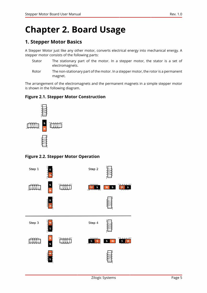
Chapter 2. Board Usage1. Stepper Motor BasicsA Stepper Motor just like any other motor, converts electrical energy into mechanical energy. Astepper motor consists of the following parts:
Stator The stationary part of the motor. In a stepper motor, the stator is a set ofelectromagnets.
Rotor The non-stationary part of the motor. In a stepper motor, the rotor is a permanentmagnet.
The arrangement of the electromagnets and the permanent magnets in a simple stepper motoris shown in the following diagram.
Figure 2.1. Stepper Motor Construction
Figure 2.2. Stepper Motor Operation

Stepper Motor Board User Manual Rev. 1.0
Zilogic Systems Page 6
When each of the electromagnet pairs is energized successively, the permanent magnet is attractedto the electromagnet, and aligns with it. This results in rotation of the permanent magnet. This isillustrated in Figure 2.2, “Stepper Motor Operation”. The stepper motor gets its name from the factthat the rotor rotates in discrete step increments.
The simple stepper motor shown in Figure 2.1, “Stepper Motor Construction”, has a step angle of 90degrees. More complex stepper motors can have step angles as low as 3.6 degrees. These steppermotors have more no. of poles in the rotor.
A complex stepper motor is shown in Figure 2.3, “Complex Stepper Motor”. The dark grey areason the rotor are South poles and light grey areas on the rotor are North poles. The stator and thepoles are arranged such that, when A1 and A2 is aligned with poles on the stator, B1 and B2 areslightly offset by a small angle from the poles on the stator.
Initially, assume that A1 and A2 are energized such that they form North and South poles,respectively. When B1 and B2 are energized to form North and South poles, the rotor rotates inthe anti-clock wise direction, to align with the limbs of the electromagnet. And in the next step A1and A2 are energized such that they form South and North poles, and so on.
Figure 2.3. Complex Stepper Motor
2. Stepper Motor Winding
The stepper motor shown in Figure 2.1, “Stepper Motor Construction” is generally constructed usingtwo electromagnets as shown in Figure 2.4, “Bipolar Wound Stepper Motor”. The stepper motor willhave two windings, indicated as A and B . For the stepper motor, to function, a mechanism shouldbe available to switch the direction of current flow in the coils. This is required so that during Step1, as indicated in Figure 2.2, “Stepper Motor Operation”, the current in Coil A flows in one direction,and during Step 3, the current in Coil A flows in the opposite direction.

Stepper Motor Board User Manual Rev. 1.0
Zilogic Systems Page 7
2.1. Bipolar Stepper Wound Motor
Figure 2.4. Bipolar Wound Stepper Motor
Consider the winding shown in Figure 2.4, “Bipolar Wound Stepper Motor”. During Step 1, Coil Ahas to be energized as follows. This will result in the required magnetic poles on the electromagnet.
Phase VoltageA1 12V
A2 Ground
During Step 3, Coil A polarity has to be reversed. To reverse the poles of the electromagnet, CoilA has to be energized as shown below
Phase VoltageA1 Ground
A2 12V
Figure 2.5. Bipolar Stepper Motor in Step 1 and Step 3
The same applies to Coil B. This type of stepper motor is called Bipolar Wound Stepper Motor.

Stepper Motor Board User Manual Rev. 1.0
Zilogic Systems Page 8
2.2. Unipolar Wound Stepper Motors
Figure 2.6. Unipolar Wound Stepper Motor
Bipolar Wound Stepper Motors, require additional circuits to reverse the polarity of the coils. Tosimplify this, another class of stepper motors called Unipolar Wound Stepper Motors, provide anadditional center tap in the windings. The center tap is always connected to the power supply, say12V. With the center tap in place, during Step 1, the phases will be driven as shown below
Phase VoltageA1 12V
COM 12V
A2 Ground
During Step 3, to reverse the magnetic poles, the phases will be driven as shown below.
Phase VoltageA1 Ground
COM 12V
A2 12V
Figure 2.7. Unipolar Stepper Motor in Step 1 and Step 3

Stepper Motor Board User Manual Rev. 1.0
Zilogic Systems Page 9
3. Drive Modes
The Drive Mode, indicates the order in which the coils are energized for the stepper motor tocomplete one turn. For the drive mode shown in Figure 2.2, “Stepper Motor Operation”, theexcitation sequence is shown in the following table. The phases indicated with a *, are driven 12V,while the other phases are connected to ground.
Phase Step 1 Step 2 Step 3 Step 4A1 *
B1 *
A2 *
B2 *
This drive mode, is called the Wave Drive. This is the simplest drive mode. The disadvantage isthat, in the case of bipolar motors, only 50% of the winding is utilized, and in the case of unipolarmotors, only 25% of the winding is utilized.
The Full Step Drive mode, utilizes the 100% of the winding in the case of bipolar motors and 50% ofthe winding in the case of unipolar motors. The excitation sequence is shown in the following table.
Phase Step 1 Step 2 Step 3 Step 4A1 * *
B1 * *
A2 * *
B2 * *
Since the winding utilized is higher than the Wave Drive mode, the Full Step Drive mode providesa higher holding torque compared to the Wave Drive mode.

Stepper Motor Board User Manual Rev. 1.0
Zilogic Systems Page 10
Appendix A. Legal Information1. Copying
This work is licensed under the Creative Commons Attribution-Share Alike 2.5 India License. Toview a copy of this license, visit http://creativecommons.org/licenses/by-sa/2.5/in/ or send a letterto Creative Commons, 171 Second Street, Suite 300, San Francisco, California, 94105, USA.
2. Limited Hardware Warranty
The warranties provided by Zilogic Systems in this Limited Hardware Warranty apply only toHardware Products you purchase for your use, and not for resale. The term "Hardware Product"means a computing device with a specific function and limited configuration ability.
2.1. LIMITED HARDWARE WARRANTY
Zilogic Systems warrants that the hardware components of its Hardware Product shall be free frommaterial defects in design, materials, and workmanship and will function, under normal use andcircumstances, in accordance with the documentation provided, for a period of one (1) year fromthe date of purchase of the Hardware Product.
Your sole and exclusive remedy, and Zilogic Systems' sole and exclusive liability for defectivehardware components, shall be that Zilogic Systems, subject to the terms and conditions ofthis Section, and solely upon confirmation of a defect or failure of a hardware component toperform as warranted, shall at its sole option, either repair or replace the nonconforming hardwarecomponent. All replacement parts furnished to you under this warranty shall be refurbished andequivalent to new, and shall be warranted as new for the remainder of the original warranty period.All defective parts, which have been replaced, shall become the property of Zilogic Systems. Alldefective parts that have been repaired shall remain your property.
2.2. EXCLUSIONS
The foregoing warranties and remedies shall be void as to any Hardware Products damaged orrendered unserviceable by one or more of the following: (1) improper or inadequate maintenanceby anyone other than Zilogic Systems or Zilogic Systems' authorized engineers, (2) interfacingsupplied by anyone other than Zilogic Systems, (3) modifications, alterations or additions to theHardware Products by personnel not certified by Zilogic Systems or Zilogic Systems' authorizedengineers to perform such acts, or other unauthorized repair, installation or other causesbeyond Zilogic Systems' control, (4) unreasonable refusal to agree with engineering changenotice programs, (5) negligence by any person other than Zilogic Systems or Zilogic Systems'authorized engineers, (6) misuse, abuse, accident, electrical irregularity, theft, vandalism, fire, wateror other peril, (7) damage caused by containment and/or operation outside the environmentalspecifications for the Hardware Products, (8) alteration or connection of the Hardware Products toother systems, equipment or devices (other than those specifically approved by Zilogic Systems) notin accordance to the board and on-board device specifications (9) any use that is inconsistent withthe user manual supplied with the Hardware Product. The warranty period is not extended if ZilogicSystems repairs or replaces a warranted product or any parts. Zilogic Systems may change theavailability of limited hardware warranties, at its discretion, but any changes will not be retroactive.
2.3. HARDWARE RETURN PROCEDURES
If a Hardware Product or one of its component parts does not function as warranted during thewarranty period, and such nonconformance can be verified by Zilogic Systems, Zilogic Systems, at
Stepper Motor Board User Manual Rev. 1.0
Zilogic Systems Page 11
its election, will provide either return and replacement service or replacement with a refurbishedpart/unit for the Hardware Product under the type of warranty service Zilogic Systems designatesfor that Hardware Product. A defective Hardware Product or one of its component parts may onlybe returned to Zilogic Systems upon Zilogic Systems' prior written approval. Any such approvalshall reference an RMA number issued by an authorized Zilogic Systems service representative. Ifyou do not register the Hardware Product with Zilogic Systems, you may be required to presentproof of purchase as evidence of your entitlement to warranty service. The Hardware Product’sserial number will be required for all RMA cases.
Transportation costs, if any, incurred in connection with the return of a defective item to ZilogicSystems shall be borne by You. Any transportation costs incurred in connection with the redeliveryof a repaired or replacement item to You by Zilogic Systems shall be borne by Zilogic Systems;provided, however, that if Zilogic Systems determines, in its sole discretion, that the allegedlydefective item is not covered by the terms and conditions of the warranty or that a warranty claimis made after the warranty period, the cost of the repair by Zilogic Systems, including all shippingexpenses, shall be reimbursed by You.
2.4. HARDWARE REPLACEMENT PROCEDURES
Zilogic Systems will attempt to diagnose and resolve your problem over the phone or e-mail. Upondetermination of the hardware issue is related to a malfunction of one of the Hardware Productcomponents, an RMA process will be initiated by Zilogic Systems.
For Warranty Replacement service, it is required that you deliver the faulty unit to a location ZilogicSystems designates, and provide courier name and tracking number to Zilogic Systems. After theFaulty unit is returned to Zilogic Systems, Zilogic Systems will use commercially reasonable effortsto ship the replacement hardware within fourteen (14) business days. Actual delivery times mayvary depending on availability of the spares and customer’s location.
2.5. ADDITIONAL RESPONSIBILITIES
You agree:
• To provide Zilogic Systems or its partner with sufficient and safe access to your facilities topermit Zilogic Systems to fulfill its obligations.
• To ship back the faulty Hardware Product (or replaceable unit) suitably packaged, quotingthe RMA number, to the Zilogic Systems designated location.
• You shall ship the faulty Hardware Product once Zilogic Systems approves the RMA andprovide the courier name and tracking number.
• To securely erase from any Hardware Product you return to Zilogic Systems for any reasonall programs and data not provided by Zilogic Systems with the Hardware Product. Youacknowledge that in order to perform its responsibilities under this Limited HardwareWarranty, Zilogic Systems may ship all or part of the Hardware Product or its software tothird party locations around the world, and you authorize Zilogic Systems to do so.
2.6. LIMITATION OF LIABILITY
Zilogic Systems' development kits are not designed, authorized or warranted to be suitable for usein medical, military, aircraft, space or life support equipment, not in applications where failure ormalfunction of a Zilogic Systems product can resonably be expected to result in personal injury,death or severe property or environmental damage.
NOTWITHSTANDING ANYTHING ELSE IN THIS AGREEMENT OR OTHERWISE, NEITHER ZILOGICSYSTEMS NOR ITS SUPPLIERS WILL BE LIABLE WITH RESPECT TO ANY SUBJECT MATTER OFTHIS AGREEMENT UNDER ANY CONTRACT, NEGLIGENCE, STRICT LIABILITY, OR OTHER LEGAL
Stepper Motor Board User Manual Rev. 1.0
Zilogic Systems Page 12
OR EQUITABLE THEORY, REGARDLESS OF WHETHER ZILOGIC SYSTEMS OR ITS SUPPLIERS WEREADVISED OF THE POSSIBILITY OF SUCH DAMAGES, FOR: (i) ANY PUNITIVE, INCIDENTAL ORCONSEQUENTIAL DAMAGES OR LOST DATA OR LOST PROFITS; OR (ii) FOR COSTS OF PROCUREMENTOF SUBSTITUTE GOODS, TECHNOLOGY OR SERVICES; OR (iii) FOR ANY CLAIMS BASED ON ANYERROR, DEFECT OR NONCONFORMITY IN THE PRODUCTS OR SERVICE, FOR ANY AMOUNT INEXCESS OF THE PRICE PAID TO ZILOGIC SYSTEMS FOR SUCH DEFECTIVE PRODUCT(S) OR SERVICE;OR (IV) FOR ALL OTHER CLAIMS NOT RELATED TO AN ERROR, DEFECT OR NONCONFORMITY INTHE PRODUCTS, ANY AMOUNTS IN EXCESS IN THE AGGREGATE OF THE AMOUNT PAID TO ZILOGICSYSTEMS HEREUNDER DURING THE THREE (3) MONTHS PRECEDING THE DATE THE CAUSE OFACTION AROSE.
WARRANTY DISCLAIMER. EXCEPT AS STATED HEREIN, ZILOGIC SYSTEMS MAKES NO WARRANTIESWITH RESPECT TO any PRODUCT, license or SERVICE AND DISCLAIMS ALL Statutory or IMPLIEDWARRANTIES, INCLUDING WITHOUT LIMITATION WARRANTIES OF MERCHANTABILITY, FITNESS FORA PARTICULAR PURPOSE, or arising from a course of dealing or usage of trade and any WARRANTIESOF NONINFRINGEMENT. ZILOGIC SYSTEMS DOES NOT WARRANT THAT THE ZILOGIC SYSTEMSPRODUCT(s) WILL MEET any REQUIREMENTS or THAT THE OPERATION OF ZILOGIC SYSTEMSPRODUCTS WILL BE UNINTERRUPTED OR ERROR FREE.


![Untitled-2 [suntracbatteries.com]suntracbatteries.com/suntrac.pdf · capacity 12v 20ah 12v 40ah 12v 60ah 12v b40ah 12v b60ah 12v b80ah 12v biooah 12v 80ah 12v iooah 12v 130ah 12v](https://static.fdocuments.us/doc/165x107/603efb7aa12c32391f5484d1/untitled-2-capacity-12v-20ah-12v-40ah-12v-60ah-12v-b40ah-12v-b60ah-12v-b80ah.jpg)
