MX-X Technical Data Very Narrow Aisle Truck (man-up) with ...

Page 1 of 16
Save costs, increase warehouse space with STEINBOCK WA-13 /15 "Depotlift"
Storage space is expensive and the costs are forever increasing. Whether yourcustomer is planning a new warehouse, or remodeling the present one, you canincrease the companies profits by optimizing the storage facilities.
Remember when offering the WA-15, every square foot of floor area saved,amounts to many additional cubic feet of storage space. All loads are storedwithin easy view of the operator.
Should you consider planning a warehouse facility, pleasecall (407) 677 - 0040 or fax (407) 678 - 0273 PMH for assistance.We'll gladly furnish you with the information and layout.
Basic Information
SSTTEEIINNBBOOCCKK WWAA--1155 AAiissllee rreeqquuiirreemmeennttss
Pallet Sideshift Pallet Insertion Aisle (guided) Aisle (guided)(samples) stroke length wire rail
48 x 40 58.7" 48" 66" 66”48.8" 40" 58" 58”
48 x 42 58.7" 48" 66" 66”52.8" 42" 60" 60”
48 x 48 58.7" 48" 66" 66”58.7" 48" 66" 66”
42 x 40 52.8" 42" 60" 60”48.8" 40" 58" 58”
40 x 40 48.8" 40" 58" 58”48.8" 40" 58" 58”
72 x 60 80.3" 72" 90" 90”68.5” 60” 78” 78”

Page 2 of 16
Larger load sizes can be handled, please contact PMH for engineeringspecifications. Large furniture pallets up to 108” or more are not uncommon.
Vehicle frame sizes(1210) (1350) (1450) (1500) (1550) (1600) (1650) (1700)47.6” 53.1" 57" 59" 61" 63” 65” 66.9
Coincide withAttachment frame sizes
48.8 52.8 58.7 60.6 62.6 64.6 68.5 72.4
(bold numbers) indicate vehicle setup for 48" pallet
Page 3 of 16
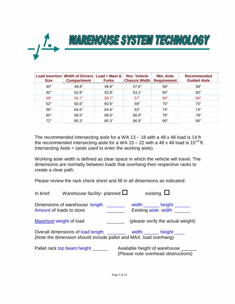
Load InsertionSize
Width of DriversCompartment
Load + Mast &Forks
Rec. VehicleChassis Width
Min. AisleRequirement
RecommendedGuided Aisle
40" 48.8" 48.8" 47.6" 58" 58"42" 52.8" 52.8" 53.1" 60" 60"48" 56.7" 58.7" 57" 66" 66"52" 60.6" 60.6" 59" 70" 70"56" 64.6" 64.6" 63" 74" 74"60" 68.5" 68.5" 66.9" 78" 78"72" 80.3" 80.3" 66.9" 90" 90"
The recommended intersecting aisle for a WA 13 – 18 with a 48 x 48 load is 14 ftthe recommended intersecting aisle for a WA 15 – 22 with a 48 x 48 load is 151/2 ft.Intersecting Aisle = (aisle used to enter the working aisle).
Working aisle width is defined as clear space in which the vehicle will travel. Thedimensions are normally between loads that overhang their respective racks tocreate a clear path.
Please review the rack check sheet and fill in all dimensions as indicated:
In brief: Warehouse facility: planned o existing o
Dimensions of warehouse length _______ width ______ height ______Amount of loads to store _______ Existing aisle width ______
Maximum weight of load _______ (please verify the actual weight)
Overall dimensions of load length _______ width ______ height ____(Note the dimension should include pallet and MAX. load overhang)
Pallet rack top beam height ______ Available height of warehouse ______(Please note overhead obstructions)

Page 4 of 16
General Information WA 13 - 18
Load Weight: 2750 lbsLoad Center: 24"
Depending on frame widths and height: (see technical publication) additionalcapacities are available at higher elevations for this frame length.
Average Capacity ratings 2750 lbs with 57” frame and 48 x 48 pallet 24” loadcenter:
2750 226.42640 246.12530 265.72420 285.42310 305.12200 324.82090 344.51980 364.2
187.0226.4265.7305.1344.547.6**
66.91700
1950
2200
2450
2700
Cap
acity
(lb
s)
Total Lift Height
Capacity at Elevation
47.6**53.1*575961636566.9
Frame Width

Page 5 of 16
General Information WA 15 - 19
Load Weight: 3300 lbsLoad Center: 24"
Depending on frame widths and height: (see technical publication) additionalcapacities are available at higher elevations for this frame length.
Average Capacity ratings 3300 lbs with 57” frame and 48 x 48 pallet 24” loadcenter:
3300 226.43080 246.12860 265.72750 285.42530 305.12420 324.82310 344.52200 364.21980 383.91870 403.51760 423.21650 442.9
187.0 246.1 305.1 364.2 423.247.6**
160018002000220024002600280030003200
Cap
acity
(lb
s)
Total Lift Height
Capacity at Elevation
47.6**53.1*575961636566.9
Frame Width

Page 6 of 16
General Information WA 15 - 19
Load Weight: 3300 lbsLoad Center: 24"
Depending on frame widths and height: (see technical publication) additionalcapacities are available at higher elevations for this frame length.
Average Capacity ratings 3300 lbs with 57” frame and 48 x 48 pallet 24” loadcenter:
3081 246.12861 265.72751 285.43300 305.13080 324.82860 344.52750 364.22530 383.92310 403.52090 423.21980 442.91870 462.61760 482.31650 502.0
226.4305.1383.9462.6541.347.6**
1400160018002000220024002600280030003200
Cap
acit
y (lb
s)
Total Lift Height
Capacity at Elevation
47.6**53.1*575961636566.9
Frame Width

Page 7 of 16
Floor loading and requirements:
The warehouse floor should be smooth industrial type flooring with a minimumfloor load capacity of 250 lbs per sq. ft. 4" reinforced concrete with 2000 P.S.I.Floors should be impervious to oils and greases.
Sample: WA 15 – 22 with a 2 stage 295.3” lift height and frame width of 57”
Without LOAD
Vehicle weight19,553 lbs(incl. Battery wt. 4,660)
Axle load Wheel Pressureattachment homeposition
Wheel Pressureattachment extended right
Steering wheel 7,739 lbs 7,739 lbs 7,739 lbs
Front wheels 11,814 lbs Left 6,107 lbsRight 5,707 lbs
Left 4,915 lbsright 6,899 lbs
With LOAD
Vehicle weight23,029 lbs withload (3300) and 175 lbsdriver
Steering 6,091 lbs 6,091 lbs 6,091 lbs
Front wheels 16,938 lbs left 9,069 lbsright 7,869 lbs
left 3,870 lbsright 13,068 lbs
Page 8 of 16
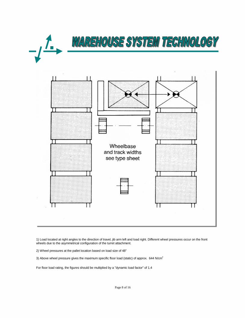
1) Load located at right angles to the direction of travel, jib arm left and load right. Different wheel pressures occur on the frontwheels due to the asymmetrical configuration of the turret attachment.
2) Wheel pressures at the pallet location based on load size of 48"
3) Above wheel pressure gives the maximum specific floor load (static) of approx. 644 N/cm2
For floor load rating, the figures should be multiplied by a "dynamic load factor" of 1.4

Page 10 of 16
Application Questionnaire
Please answer the following questions to determine WA –13 /15 vehicleparameters:
Short description of current transportation and handling method.
A. Load Unit information (Pallet)
Type of load:_____________________________________________________(eg. loose / stabile / wrapped / etc.)
Loads stored on: * please do not include the load dimensions at this time
o Pallet length _____ width _____ height _____
o Skid length _____ width _____ height _____
o Container length _____ width _____ height _____
Do you intend to handle pallets, skids, or containers of different sizes?
o Yes _________________
o No _________________
If yes please list max. and minimum sizes

Page 11 of 16
Will loads be handled by inserting its length into the rack opening (width of palletfaces aisle)
orWill loads be handled by inserting its width into the rack opening (load lengthfaces aisle - only possible with four way entry pallet, skid, or container)
Does the product overhang the pallet, skid, or container o YES
o NO
If larger, what is the overhang front & rear ________________ sides ________________
Please indicate if the loads are smaller or equal or in size to the pallet
Smaller oEqual o
Desired aisle size ________ (minimum aisle 18" + load insertion length)
Smaller aisles available utilizing WD & WA model vehicles.
B. Load movements and length of workday
Amount of pallets moved during day _____ / # _____of shift cyclesLength of workday _____ hrsLength of shift _____ hrs
Loads received per shift _____Loads shipped per shift _____
Average distance to storage location _____Average lifting height _____(Distance from entry of warehouse to center aisle add half the distance ofworking aisle length)
Page 12 of 16
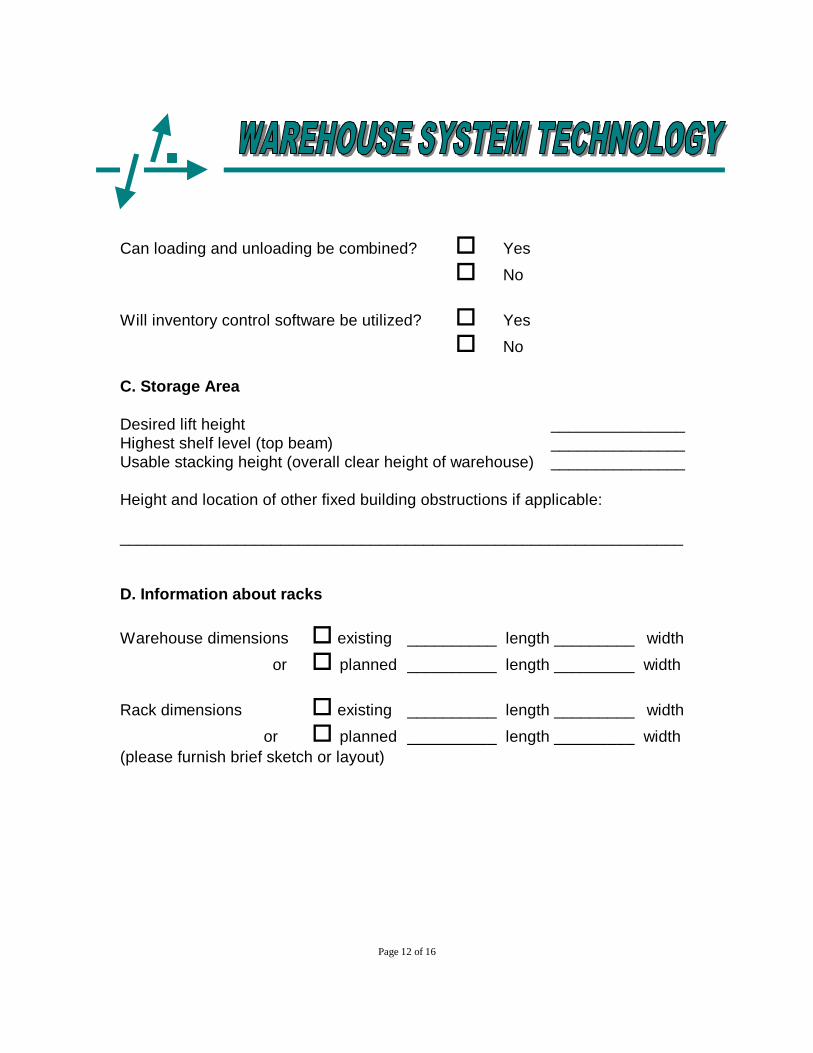
Can loading and unloading be combined? o Yes
o No
Will inventory control software be utilized? o Yes
o No
C. Storage Area
Desired lift height _______________Highest shelf level (top beam) _______________Usable stacking height (overall clear height of warehouse) _______________
Height and location of other fixed building obstructions if applicable:
_______________________________________________________________
D. Information about racks
Warehouse dimensions o existing __________ length _________ width
or o planned __________ length _________ width
Rack dimensions o existing __________ length _________ width
or o planned __________ length _________ width(please furnish brief sketch or layout)

Page 13 of 16
Rack Structure:
Height of Upright frame
Top Beam elevation
No. of storage levels
Clear beam span
Clear shelf height
No. of pallets per bay
Clearance betweenpallets / rack upright
Aisle width between loads: o current ______ o planned ______
Aisle width between rack uprights o current ______ o planned ______
E. Guide Rails
Existing application o Yes
o No
Recommend guide rails as per attached sketchRemember lowest load must be raised to accommodated guide rails
Wire guided application
Recommended wire guide path and layout as per sample sketch

Page 14 of 16
F. Other information
Door openings to be negotiated __________ height x __________ width
Environment conditions
Cooler temp
Freezer temp
Wet storage
Dust conditions
Abrasive material
Flammable goods
G. Required Equipment
Number of vehicles __________
Battery AH ________ Number of Batteries __________Multiple shift ______ change batteries __________
Charge Input voltage Single phase or Three phase
H. Optional Equipment
Light optical load alignment o YES o NO
Safety lift limitations w/override o YES o NO
Work lights o YES o NO
Operator compartment light o YES o NO
Mirror o YES o NO
End of aisle slowdown / stop o YES o NO

Page 15 of 16

Page 16 of 16
Line Driver
Sample layout depicts (2) single &(3) back-to-back rows of rack 100 ft long. An aislewidth of 66" and an intersecting aisle of 12 ft. Thelength of wire used is approx. 520 ft.
The guide wire is covered with a flexibleinsulation. The wire will be installedapproximately 1/4" below the surface of thefloor.
One line driver will supply the requiredfrequency to a loop of max. 4000 ft. Forlarger installations a second line drivershould be installed.
The concrete floor should be level and meetspecifications stated on previous pages. Anyfloor reinforcements must be at least 2"below the surface. Large metallic objects aswell as underground power lines should bekept at a safe distance from the guide wire.
In case of unavoidable interference contactthe PMH. To calculate the cost for the wireinstallation, multiply length of aisles and addconnecting length of wire between aisles toform a continuous circuit.
The guide wire from the load aisles shouldextend 8 - 10 ft into the intersecting aisles.The return wire must be kept a minimum of 2ft apart.
Layout depicts (2) single & back-to-back rows ofrack. Length of wire approx. 500 ft.