Steeringand Advanced Textbook Suspension Systems…
70
Advanced Steering and Suspension Systems Damage Analysis Textbook Version: 16.1 © 2014 Inter-Industry Conference On Auto Collision Repair DAM15-STMAN1-E
Transcript of Steeringand Advanced Textbook Suspension Systems…

AdvancedSteering�andSuspension
Systems�DamageAnalysis
Textbo
ok
Version:�16.1
©�2014�Inter-Industry�Conference�On�Auto�Collision�Repair
DAM15-STMAN1-E

This�page�is�intentionally�left�blank.

Advanced�Steering�and�Suspension�Systems�Damage�AnalysisTextbook
Table�of�Contents 3
Contents
Introduction..............................................................................................................................7Obligations�To�The�Customer�And�Liability.......................................................................... 7
Module�1�-�Electronically�Controlled�Systems........................................................................13Electronically�Controlled�Systems....................................................................................... 13Computer�Controlled�System�Basics................................................................................... 15Problem�Solving�System�Failures........................................................................................ 18Module�Wrap-Up............................................................................................................... 22
Module�2�-�Electronically�Controlled�Steering........................................................................25Electronically�Controlled�Steering.......................................................................................25Hydraulic�Variable�Assist�Steering...................................................................................... 30Electro-Hydraulic�Power�Steering........................................................................................34Electric�Assist�Power�Steering............................................................................................. 36Electric�Steering.................................................................................................................. 40Module�Wrap-Up............................................................................................................... 42
Module�3�-�Electronically�Controlled�Suspension...................................................................45Types�Of�Electronic�Suspensions........................................................................................ 45Air�Shock�Absorber�Height�Control�Systems....................................................................... 48Activity:�Suspension�Problem..............................................................................................50Load�Leveling�/�Self-Leveling�Suspension�Systems...............................................................51Hydraulic�Height�Control�Systems......................................................................................54Computer�Controlled�Dampers...........................................................................................58Computer�Controlled�Stabilizer�Bars...................................................................................63Tire�Pressure�Monitors........................................................................................................ 66Module�Wrap-Up............................................................................................................... 70

This�page�is�intentionally�left�blank.

Introduction

This�page�is�intentionally�left�blank.

IntroductionTextbook
Advanced�Steering�and�Suspension�Systems�Damage�Analysis 7
Obligations�To�The�Customer�And�Liability
The�collision�repair�industry�has�anobligation�to�correctly�repair�thecustomer’s�vehicle.�Collision�repairs�mustbe�performed�using:
• recommended�or�testedprocedures�from�vehicle�makers,I-CAR,�and�other�research�andtesting�organizations.
• quality�replacement�parts�andmaterials.
• repair�processes�and�parts�aswritten�and�agreed�upon�in�therepair�order.�If�items�on�the�repairagreement�are�not�consistentwith�the�repair�order,�it�can�beconsidered�fraud.
Performing�proper�collision�repairsrequires�using�parts�and�procedures�thatkeep�remaining�warranties�intact.
Collision�repairs�must�restore:
• safety.• structural�integrity.• durability.• performance.
• fit.• finish.
Throughout�the�damage�analysis�andrepair�process�the�repairer�and�insurermust:
• communicate�with�each�other.• maintain�constant�communication
with�the�customer.• be�in�agreement�with�each�other
and�the�customer�on�how�repairswill�be�performed.
• inform�the�customer�of�anychanges�in�the�repair�plan�fromthe�original�repair�agreement,�andexplain�the�changes�and�why�theyhave�to�be�made.
To�reduce�liability:
• make�sure�that�all�repairs�areperformed�thoroughly,�correctlyand�as�listed�in�the�damage�report.
• follow�proper�procedures.• have�documentation�of�required
repairs�with�detailed�recordkeeping�available�for�customers.

IntroductionTextbook
Advanced�Steering�and�Suspension�Systems�Damage�Analysis 8
Technicians�are�considered�theexperts�and�are�expected�to�beknowledgeable�on�how�to�performa�quality�repair.
Liability�insurance�that�covers�the�repairfacility�may�not�always�cover�all�damages.For�example:
• the�policy�may�not�coverfaulty�repairs,�leaving�liabilityresponsibility�completely�on�thefacility.
• a�shop�owner�may�find�that�repairfacility�liability�coverage�may�notcover�the�full�amount�awarded�ina�lawsuit.�The�shop�owner�wouldhave�to�pay�the�difference.
It�is�difficult�to�reduce�the�risk�of�liabilityexposure.�The�part�that�the�repairer�cancontrol�is�the�chance�of�being�found�atfault.�Chances�can�be�minimized�by:
• using�recommended�or�testedprocedures�from�the�vehiclemakers,�I�CAR,�or�other�researchand�testing�organizations.
• using�quality�replacement�partsand�materials�that�restore�fit,
finish,�durability,�and�perform�atleast�as�well�as�the�original.
• keeping�thorough�records.
Keeping�thorough�records�includes�morethan�recording�the�date,�mileage,�and�pre-existing�damage.�Record�keeping�alsoincludes:
• making�sure�all�notes�are�legible.• verifying�the�repairs�that�were
made�or�not�made.• having�the�customer�sign�a
waiver�for�repairs�that�they�donot�want�performed.�Repairersmust�determine�their�liability�onnot�repairing�safety�systems�suchas�restraint�and�anti-lock�brakesystems.
• keeping�computer�printouts�orworksheets�on�file�showing�wheelalignment�readings�or�vehicledimensions�before�and�afterrepairs.
• keeping�scan�tool�printouts�andrecords�of�computer�codes�forairbag,�anti-lock�brake,�emission,and�powertrain�control�module(PCM)�systems.

IntroductionTextbook
Advanced�Steering�and�Suspension�Systems�Damage�Analysis 9
• attaching�the�OEM�or�other�testedprocedure�printout�to�the�vehiclerepair�order.
• keeping�receipts�for�all�subletwork�performed.
Refer�to�"Video:�Topics�Off�Limits"�in�thepresentation.�This�video�identifies�topicsthat�should�not�be�brought�up�in�class.

This�page�is�intentionally�left�blank.

Module�1�-Electronically
Controlled�Systems

This�page�is�intentionally�left�blank.

Module�1�-�Electronically�Controlled�SystemsTextbook
Advanced�Steering�and�Suspension�Systems�Damage�Analysis 13
Electronically�Controlled�Systems
Refer�to�"Video:�Learning�Objectives"�inthe�presentation.
The�learning�objectives�for�this�moduleinclude:
• explaining�electronic�circuitoperation.
• identifying�electronic�system�parts.• diagnosing�problems�with
electronic�circuits.• explaining�basic�problem�solving
steps�for�electronically�controlledsystems.
Mercedes-Benz�E-Class
This�Mercedes-Benz�E-Class�Coupe�is�equippedwith�both�electronically�controlled�steering�andsuspension.
Electronically�controlled�steering�andsuspension�systems�are:
• computer�controlled�mechanicalsystems.�They�are�adjustablesystems�that�have�the�adjustmentscontrolled�on�a�continualbasis�by�the�electronic�controlmodule�(ECM)�of�the�system.The�mechanical�parts�of�thesystem�are�similar�to�those�foundin�conventional�steering�andsuspension�systems�in�regardsto�their�attachment,�with�theexception�of�electrical,�air,�andfluid�line�connections.
• designed�to�allow�differentcharacteristics�for�steering�andsuspension�feel�with�varyingdriving�conditions�such�asvehicle�speed�and�road�surfacecharacteristics.

Module�1�-�Electronically�Controlled�SystemsTextbook
Advanced�Steering�and�Suspension�Systems�Damage�Analysis 14
Physical�damage�can�affect�many�parts�of�advancedsteering�and�suspension�systems.
Electronic�or�computer�controlled�steeringand�suspension�systems�on�vehicles�thathave�been�in�a�collision�are�subject�to:
• the�same�types�of�mechanicaldamage�as�conventional�steeringand�suspension�systems.Mechanical�parts,�such�as�shockabsorbers,�struts,�steering�racks,and�other�steering�and�suspensionparts,�can�be�bent�or�damaged.When�analyzing�damage�oncollision�damaged�vehicles,use�the�advantage�of�knowingwhere�the�damage�to�the�vehicleis�located.�A�complete�damageinspection�may�require�somedisassembly�to�help�locate�anyhidden�damage�to�electronicallycontrolled�steering�and�suspensionparts.
• physical�damage�to�electrical�andelectronic�parts�of�the�system.Many�electronic�problems�oncollision�damaged�vehicles�can�betraced�to�physically�damaged�partsof�the�electrical�circuit.
More�information�on�the�types�ofmechanical�damage�that�may�occur�toparts�of�electronically�controlled�steeringand�suspension�systems�can�be�found�inSuspension�Systems�(STE02)�and�Rack�andPinion�and�Parallelogram�Steering�Systems(STE03).
Inspecting�for�collision�damage�includes�checkingconnectors�for�cracks�or�breakage.
Electrical�and�electronic�problemsassociated�with�collision�damage�includedamaged:
• wiring�and�connectors.�Thisincludes�cut�wires�and�damagedwiring�insulation,�which�maycause�electrical�shorts.�Connectorsmay�be�cracked�or�smashed,creating�high�resistance�or�opens.Wires�that�have�been�stretched�orpinched�between�other�parts�mayhave�wire�strands�broken�insidethe�insulation�with�no�apparentbreak�in�the�outer�insulation.
• or�burned�fuses.�Burned�fuses�maybe�a�symptom�of�another�problem,such�as�damaged�wiring�or�shortedelectrical�parts.
• relays�and�solenoids.• input�sensors�and�loads.• or�shorted�control�modules.
Module�1�-�Electronically�Controlled�SystemsTextbook
Advanced�Steering�and�Suspension�Systems�Damage�Analysis 15
Electronic�parts�can�be�nonfunctional�withno�signs�of�physical�damage.
KPI�Improvement�TipCareful�inspection�includes�ensuringthe�water�tight�seal�is�intact�and�remainswith�connectors�that�are�going�back�inservice. This�helps�prevent future�systemfailure�from�water�infiltration.
Computer�Controlled�System�Basics
This�wiring�diagram�shows�the�two�circuits,�inputand�output,�that�make�up�a�typical�electronicallycontrolled�system.
Computer�controlled�systems:
• are�made�up�of�two�or�moreinterconnected�circuits.
• contain�an�input�circuit�that�hasthe�wiring�and�input�sensorsthat�send�signals�to�the�controlmodule.�The�input�signals�aretypically�voltage,�resistance,�oramperage�values.�Input�signalsmay�also�be�frequency�values,such�as�a�toothed�tone�ring�usedfor�wheel�speed�sensors�in�an�ABSsystem.�Input�signals�may�alsocome�from�control�modules�forother�vehicle�systems.
• have�an�output�circuit�containingthe�control�module,�wiring,�andload�that�is�controlled�by�thecontrol�module.�Solenoid�valvesinside�shock�absorbers�or�steering
control�valves�are�examples�ofloads�in�electronic�steering�andsuspension�systems.
The�input�and�output�circuits�of�thesystems�typically�contain�and�share�thecontrol�module.
The�control�module�for�an�electronically�controlledsteering�system�on�a�Honda�Civic�is�located�belowthe�instrument�panel�on�the�driver�side.
Typical�parts�of�an�electronic�circuitinclude�the�power�source,�load,�switch,fuse,�and�wiring,�as�well�as�the:
• control�modules.�Control�modulesreceive�inputs�from�varioussources�that�are�processed�andused�to�calculate�the�requiredoutputs�that�are�supplied�to�theload.�A�control�module�mayserve�as�the�switch�for�the�circuitcontaining�the�load.
• input�sensors.�Input�sensors�supplysignals�to�the�control�module�thatare�used�to�calculate�the�requiredoutput.�Other�control�modulesmay�supply�input�signals�into�thecircuit.

Module�1�-�Electronically�Controlled�SystemsTextbook
Advanced�Steering�and�Suspension�Systems�Damage�Analysis 16
This�is�a�MIL�on�a�vehicle�with�an�electronicallycontrolled�steering�system�problem.
Malfunction�indicator�lamps�(MILs)�are:
• used�to�warn�of�problems�andstored�diagnostic�trouble�codes(DTCs)�in�a�circuit.
• designed�to�be�on�when�the�circuitis�energized�and�are�turned�offby�the�control�module�after�self-diagnostic�checks�of�the�circuitare�completed�and�no�problem�isdetected.�This�is�done�to�allow�thelamp�to�be�on�when�the�key�is�firstturned�ON,�ensuring�that�the�lampis�functional.
• used�to�indicate�system�problems.A�MIL�that�remains�lit�typicallyindicates�a�problem�within�theelectronic�or�electrical�parts�of�thesystem.
A�MIL�that�remains�lit�does�not�alwaysindicate�that�parts�have�to�be�replaced,just�that�a�problem�exists�within�thesystem.
Some�vehicles�use�an�information�message�centerinstead�of�a�MIL�to�warn�of�system�problems.
The�information�message�center:
• warns�of�vehicle�system�problems.• displays�a�text�message�on
the�instrument�cluster.�Thesemessages�are�used�to�warn�ofsystem�problems�instead�of�havingseparate�MILs�for�each�system.
• is typically�used�in�vehicles�withmultiple�advanced�auxiliarysystems,�such�as�the�tire�pressuremonitoring�system�(TPMS).
Scan�tool�software�is�being�used�to�diagnose�aproblem�in�an�electronic�circuit.
Computer�controlled�circuits�are�typicallycapable�of�self-diagnosis.�They�can

Module�1�-�Electronically�Controlled�SystemsTextbook
Advanced�Steering�and�Suspension�Systems�Damage�Analysis 17
also�retain�DTCs�that�are�used�to�locateproblems�in�the�circuit.�When�diagnosingproblems�with�computer�controlledcircuits:
• DTCs may�be�read�by�a�scan�toolor�by�using�a�laptop�with�theappropriate�application.�Somesystems�require�a�vehicle-specificscan�tool�be�used�to�retrieve�storedDTCs�for�computer�controlledsteering�and�suspension�systems.
• verify�that�the�system�ismechanically�correct,�with�nophysical�parts�damage,�beforediagnosing�electrical�problems.The�mechanical�side�of�the�systemmust�function�correctly�for�theelectronic�control�system�to�workproperly,�to�allow�for�completeand�accurate�damage�analysis.
• look�for�a�MIL�or�a�troublemessage�on�the�informationmessage�center�on�the�instrumentcluster.�A�MIL�or�trouble�messageon�the�information�message�centerindicates�a�stored�DTC�that�maybe�retrieved�to�help�locate�theproblem.�For�example,�problemsmay�turn�on�indicator�lamps�suchas�ABS,�traction�control,�stabilitycontrol,�and�low�tire�pressure.
• use�the�diagnostic�flowcharts�thatcorrespond�with�the�DTC.�Theflowcharts�will�call�for�specificelectrical�and�/�or�mechanicaltest�procedures�to�help�locatethe�faulty�part�or�wiring.�Testingparts�of�the�system�will�typicallyinvolve�measuring�for�eithervoltage,�resistance,�or�amperage,or�checking�fluid�pressure,�and
comparing�the�values�to�listedspecifications.�Electrical�testingwill�typically�require�a�DVOM.When�using�diagnostic�flowchartsread�the�entire�flowchart�beforebeginning�diagnosis.�This�will�helpto�understand�what�the�causesof�the�problem�may�be.�Usingthis�information�together�with�aknowledge�of�where�the�vehicle�isphysically�damaged�may�shortendiagnostic�time.
Some�systems�on�older�model�vehiclesmay�show�DTCs�by�flashing�a�codewith�the�MIL.�The�flash�code�may�beautomatically�displayed�if�a�DTC�is�storedor�it�may�require�a�specific�procedure,such�as�shorting�between�pins�on�adiagnostic�connector,�to�activate�it.�Followthe�vehicle�maker’s�procedure�for�theactivation�of�flash�code�diagnostics.Vehicle�makers�have�gone�away�from�thistype�of�diagnostics.
Take�appropriate�precautions�when�disconnectingcontrol�module�connectors.
During�damage�analysis�and�repairs,precautions�need�to�be�taken�to�protectcontrol�modules�from:

Module�1�-�Electronically�Controlled�SystemsTextbook
Advanced�Steering�and�Suspension�Systems�Damage�Analysis 18
• excessive�current�and�voltage.Have�the�ignition�switch�in�theLOCK�position�and�the�key�outunless�otherwise�specified�fora�specific�procedure. Keep�thevehicle�battery�connected�forproper�diagnosis�unless�otherwisespecified�for�a�procedure,�personalsafety,�or�vehicle�protection.
• excessive�heat.�Ensure�that�controlmodules�will�be�protected�ifrepairs�require�heat�to�be�appliedor�welding�to�be�done�in�closeproximity.�Normal�sprayboothcuring�temperatures�are nothigh�enough�to�damage�controlmodules.
• vibration�and�shock.�To�protectcontrol�modules�from�damagedue�to�vibration�and�shock,�theyshould�be�removed�from�areaswhere�air�chisels�or�hammers�willbe�used�in�close�proximity.
• moisture.
When�disconnecting�control�modules�andelectrical�connectors:
• control�static�electricitydischarge�by�wearing�anelectrostatic�discharge�strap�whiledisconnecting�and�handling�themodules.
• protect�the�connectors�fromcontamination�by�covering�theends�with�tape�or�plastic�bags.
• ensure�that�the�connector�pins�arenot�bent�or�damaged.
Problem�Solving�System�Failures
This�chart�shows�the�recommended�steps�for�solvinga�problem�in�an�electronically�controlled�system.
Recommended�steps�in�solving�problemsin�computer�controlled�systems:
1. Define�the�problem.2. Understand�how�the�system
works.3. Find�the�cause�of�the�problem.4. Make�the�repair�to�the�system.5. Test�the�system�to�verify�the
problem�has�been�repaired.
Cadillac�Escalade
The�technician�is�measuring�the�vehicle�ride�heightto�help�define�a�problem�with�the�electronicallycontrolled�suspension�system.
Defining�the�problem�with�a�computercontrolled�vehicle�system�includes:
• determining�what�does�not�work.
Module�1�-�Electronically�Controlled�SystemsTextbook
Advanced�Steering�and�Suspension�Systems�Damage�Analysis 19
• isolating�the�problem.�Determineif�anything�else�is�malfunctioning.Other�malfunctioning�parts�orsystems�may�be�related.
• determining�if�the�system�is�tryingto�work�but�cannot�because�ofsome�mechanical�problem.�Anexample�of�this�would�be an�airspring�that�the�system�is�trying�toinflate�but�cannot�because�of�aleak�in�an�air�line.
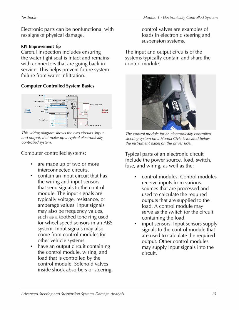
The�vehicle�service�information�should�be�referencedto�help�with�understanding�how�a�system�operates.
Understanding�how�the�system�works�iscritical�when�checking�if�it�is�functioningproperly�and�includes:
• using�the�vehicle�serviceinformation.�Service�informationsources�may�contain�systemdescription�and�operationsections.�They�also�typicallycontain�system�wiring�diagrams,part�location�charts,�and�symptomand�DTC�flowcharts.
• checking�for�any�technical�servicebulletins�(TSBs)�that�may�pertain�tothe�system�or�the�specific�problembeing�diagnosed.
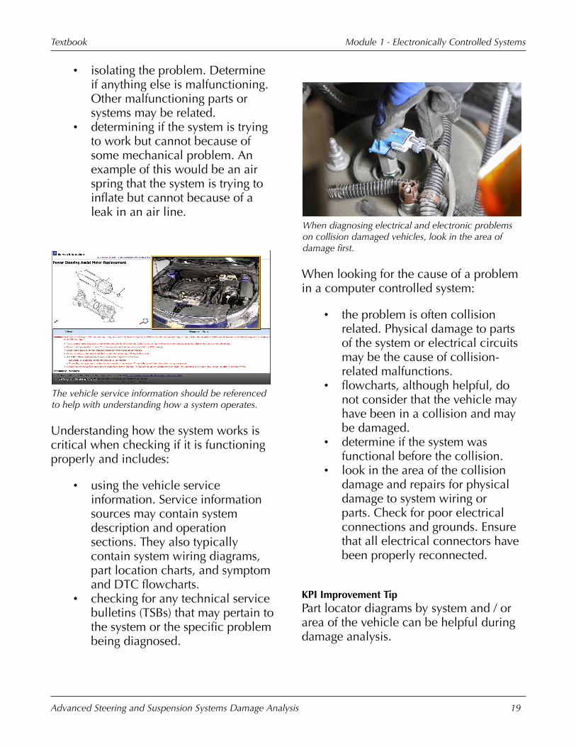
When�diagnosing�electrical�and�electronic�problemson�collision�damaged�vehicles,�look�in�the�area�ofdamage�first.
When�looking�for�the�cause�of�a�problemin�a�computer�controlled�system:
• the�problem�is�often�collisionrelated.�Physical�damage�to�partsof�the�system�or�electrical�circuitsmay�be�the�cause�of�collision-related�malfunctions.
• flowcharts,�although�helpful, donot�consider�that�the�vehicle�mayhave�been�in�a�collision�and�maybe�damaged.
• determine�if�the�system�wasfunctional�before�the�collision.
• look�in�the�area�of�the�collisiondamage�and�repairs�for�physicaldamage�to�system�wiring�orparts.�Check�for�poor�electricalconnections�and�grounds.�Ensurethat�all�electrical�connectors�havebeen�properly�reconnected.
KPI�Improvement�TipPart�locator�diagrams�by�system�and�/�orarea�of�the�vehicle�can�be�helpful�duringdamage�analysis.

Module�1�-�Electronically�Controlled�SystemsTextbook
Advanced�Steering�and�Suspension�Systems�Damage�Analysis 20
The�technician�is�locating�a�fuse�for�a�circuit�that�isinoperable.
Additional�procedures�that�can�beperformed�to�find�the�cause�of�problemsinclude:
• checking�the�fuse�for�the�circuitinvolved.
• checking�for�available�voltage�atvarious�points�in�the�circuit.
• checking�the�operation�of�the�load.This�may�involve�testing�electricmotors�or�solenoids.�Testingparts�of�the�system�will�typicallyinvolve�measuring�for�eithervoltage,�resistance,�or�amperage,or�checking�fluid�pressure,�andcomparing�the�values�to�listedspecifications.
• using�symptom-based�flowcharts.Many�systems�may�have�symptom-based�flowcharts�to�help�isolatethe�cause�of�mechanical�problemsthat�do�not�set�DTCs.
• using�a�scan�tool�to�retrieve�DTCs.The�DTC�will�typically�lead�to�adiagnostic�flowchart�that�can�befollowed�to�isolate�the�cause�of�theproblem.
This�estimator�is�looking�up�a�repair�procedure�in�thevehicle�service�information.
To�make�repairs�to�the�system:
• follow�vehicle�makerrecommendations�for�theprocedure�being�performed.
• replace�damaged�or�defectiveparts.
• repair�or�replace�damaged�wiringand�connectors.
• clear�any�stored�DTCs�after�repairsare�complete.
KPI�Improvement�TipIt�is�a�good�practice�to�first�record�thecodes�before�clearing�in�case�follow-upon�a�code�is�necessary�later.�If�possible,test�drive�after�clearing�codes,�then�checkif�any�codes�remain�active.�Some�codesmay�be�in�the�control�module�from�aprevious�problem.

Module�1�-�Electronically�Controlled�SystemsTextbook
Advanced�Steering�and�Suspension�Systems�Damage�Analysis 21
This�vehicle�is�being�taken�for�a�test�drive�to�helpverify�proper�system�function.
After�repairs�have�been�completed,�testthe�system�to�verify�that�the�system�isfunctioning�properly.�When�testing�thesystem�for�proper�operation:
• look�for�a�MIL�that�remains�lit.• check�for�a�stored�DTC.�It�may
require�the�vehicle�to�be�drivenfor�a�DTC�to�be�set�or�a�MIL�tolight.�Some�systems�may�set�aDTC�without�lighting�a�MIL.�Ascan�tool�can�be�used�to�checkfor�the�presence�of�a�DTC�in�thesesystems.�Mechanical�problemswithin�the�system�may�not�alwaysset�a�DTC.
• a�test�drive�may�be�requiredto�ensure�that�the�system�isfully�functional�and�operatingproperly.�Test�the�vehicle�underall�conditions�applicable�tothe�system�being�checked.�Forexample,�if�testing�a�speed-related�variable�effort�powersteering�system,�the�vehicleshould�be�driven�and�steeredat�a�variety�of�speeds�to�ensurethat�the�system�is�functioningproperly.�Use�information�fromthe�service�manual�to�determine
what�conditions�need�to�bemet�to�ensure�that�the�system�isfunctioning�as�intended.
• document�what�was�done�to�testthe�system.
For�systems�that�do�not�supply�obviousindicators�of�proper�functioning�anddo�not�have�MILs,�one�possible�way�ofdetermining�that�they�are�working�is�todisable�the�system�and�then�drive�thevehicle�to�see�if�there�is�a�noticeabledifference.�An�example�of�this�again�isa�speed-related�variable�effort�powersteering�system.�It�may�be�difficult�tonotice�the�difference�in�steering�effort�atdifferent�speeds.
To�verify�that�the�system�is�functioning,the�vehicle�can�be�driven,�the�variablepower�steering�system�disabled,�andthe�vehicle�driven�again.�If�the�system�isfunctional,�there�should�be�a�noticeabledifference�in�the�way�the�vehicle�driveswith�the�system�disabled.�Use�a�servicemanual�to�determine�the�best�way�todisable�the�system.�This�may�be�doneby�unplugging�electrical�connectors�orremoving�fuses.�Before�using�this�method,check�that�driving�the�vehicle�with�thesystem�disabled�will�not�set�a�DTC�thatwill�require�clearing�with�a�scan�tool.
Module�1�-�Electronically�Controlled�SystemsTextbook
Advanced�Steering�and�Suspension�Systems�Damage�Analysis 22
Refer�to�Module�1,�"Activity:�Using�aDTC�Flowchart"�in�the�presentation.�Thisactivity�will�show�how�a�DTC�flowchartis�used�to�pinpoint�a�faulty�part�or�wiringon�an�electronically�controlled�steering�orsuspension�system.
Module�Wrap-Up
Topics�discussed�in�this�moduleincluded:
• electronic�circuit�operation.• electronic�system�parts.• diagnosing�problems�with
electronic�circuits.• basic�problem�solving�steps�for
electronically�controlled�systems.
Module�2�-Electronically
Controlled�Steering

This�page�is�intentionally�left�blank.

Module�2�-�Electronically�Controlled�SteeringTextbook
Advanced�Steering�and�Suspension�Systems�Damage�Analysis 25
Electronically�Controlled�Steering
Refer�to�"Video:�Learning�Objectives"�inthe�presentation.
The�learning�objectives�for�this�moduleinclude:
• identifying�types�of�electronicsteering�systems.
• explaining�the�operation�ofcomputer�controlled�variable�assistpower�steering�systems.
• identifying�electronic�steeringsystem�parts.
• diagnosing�problems�withelectronically�controlled�steeringsystems.
• identifying�cautions�whenanalyzing�damage�on�vehicleswith�electronically�controlledsteering�systems.
• explaining�electric�rear�steeringsystems.
This�illustration�shows�the�main�parts�of�aconventional�power�steering�system�with�a�cutawayinset�of�a�conceptual�spool�valve.
Conventional�power�steering�systems�havea:
• fluid�pump.�The�fluid�pump�is�belt-driven�off�the�engine.
• rotary�or�spool�valve.�The�fluidpump�supplies�pressurizedhydraulic�fluid�to�a�spool�valvethat�is�located�in�the�steering�gear.The�spool�valve�has�inner�andouter�parts�with�fluid�ports�thatdirect�the�fluid�to�each�side�of�thesteering�gear.�At�rest,�the�spoolvalve�directs�equal�amounts�offluid�to�each�side�of�the�steeringgear.�When�the�steering�wheel�isturned,�fluid�pressure�is�directedto�one�side�of�the�gear�only.�Fluidpressure�on�only�one�side�helpsturn�the�steering�gear�and�reducesthe�effort�needed�to�turn�thesteering�wheel.
• torsion�bar.�The�spool�valve�isconnected�to�a�torsion�bar�thatis�located�between�the�lowersteering�shaft�and�the�steeringgear.�The�outer�part�of�the�spoolvalve�is�connected�to�the�bottomof�the�torsion�bar�and�the�inner

Module�2�-�Electronically�Controlled�SteeringTextbook
Advanced�Steering�and�Suspension�Systems�Damage�Analysis 26
part�is�connected�to�the�top�of�thetorsion�bar.
As�the�steering�shaft�is�turned,�the�torsionbar�twists�and�turns�the�two�parts�of�thespool�valve�different�amounts.�As�the�partsof�the�spool�valve�turn,�fluid�ports�in�eachpart�are�aligned�with�each�other�allowingpower�steering�fluid�to�flow�through�thevalve.�The�stiffness�of�the�torsion�shaftcontrols�how�much�it�will�twist�and�howwell�the�fluid�ports�will�align.�The�betterthe�ports�align,�the�higher�the�steeringassist�level.
The�stiffness�of�the�torsion�shaft�and�speedat�which�the�power�steering�pump�isbeing�driven�are�what�determines�howmuch�assist�a�power�steering�system�willdeliver.
Refer�to�Module�2,�"Video:�Animation�OfPower�Steeering�System"�This�animationshows�the�operation�of�a�conventionalpower�steering�system.
Ford�Fusion
An�electronically�controlled�power�assist�steeringsystem�makes�the�steering�effort�easier�when�turningthe�vehicle.
Electronically�controlled�power�steeringsystems�provide:
• varied�levels�of�power�steeringassist�as�vehicle�speed�changes.Steering�assist�is�typically�reducedas�vehicle�speed�increases.�Thisis�done�to�provide�more�roadfeel,�to�reduce�oversteering�athigh�speeds,�and�for�increaseddirectional�stability.
• full�assist�at�low�speeds�forincreased�steering�ease�duringparking�and�cornering.
• full�assist�with�quick�steeringinputs,�such�as�evasive�maneuverson�some�systems,�while�othersystems�will�provide�reduced�assistlevels�under�the�same�scenario.
Most�vehicle�makers�offer�electronicallycontrolled�variable�assist�power�steeringas�an�option�on�at�least�some�vehicles.

Module�2�-�Electronically�Controlled�SteeringTextbook
Advanced�Steering�and�Suspension�Systems�Damage�Analysis 27
This�is�one�example�of�an�electronically�controlledhydraulic�variable�assist�power�steering�system.
Electromagnetic�fields�control�and�vary�the�hydraulicfluid�flow�in�this�type�of�electronically�controlledpower�steering�system.
The�level�of�steering�assist�in�anelectronically�controlled�steering�systemmay�be�varied�in�a�number�of�differentways�depending�on�the�type�of�systemused.�Types�of�electronically�controlledsteering�include:
• variable�assist�hydraulic�powersteering.�These�systems�operate�byvarying�the�flow�and�pressure�ofhydraulic�fluid�to�the�spool�valve.
• electro-hydraulic�power�steering.These�systems�use�an�electricmotor�to�drive�the�hydraulic�fluidpump.
• electric�assist�power�steering.These�systems�use�an�electricmotor,�instead�of�hydraulics,�toprovide�steering�assist.
• electric�steer�or�steer-by-wire.These�systems�use�an�electricmotor,�instead�of�a�mechanicalshaft,�to�turn�the�wheels.�Electricsteer�is�typically�used�for�therear�steering�of�4-wheel�steeringsystems.
Vehicle�makers�use�varying�terminologyfor�electronically�controlled�powersteering�systems.�Some�examplesinclude:
• Variable�Effort�Steering�(VES),commonly�used�to�describe�theelectronic�power�steering�systemon�General�Motors�vehicles.
• Magnasteer,�a�trademarkedname�of�Delphi�AutomotiveSystems,�that�General�Motorsuses�to�describe�the�magneticallycontrolled�variable�assist�powersteering�system�used�on�somevehicles.
• Electric�Power�Assist�Steering(EPAS)�on�Ford�vehicles.
• Speed�Sensitive�Steering.�Toyota,Lexus,�Mercedes-Benz,�Volvo,and�Nissan�are�among�the�vehiclemakers�that�use�this�terminology.
• Electro-Hydraulic�Power�Steering,which�is�a�term�used�by�a�varietyof�vehicle�makers�including�BMW,General�Motors,�and�Toyota.
• Servotronic�Steering.�Audi,�Jaguar,and�BMW�are�among�the�vehiclemakers�that�use�this�terminology.

Module�2�-�Electronically�Controlled�SteeringTextbook
Advanced�Steering�and�Suspension�Systems�Damage�Analysis 28
This�technician�is�pointing�to�the�electric�assistpower�steering�motor�on�a�Honda�Civic.
The�presence�of�electronically�controlledsteering�systems�is�typically�not�notedby�emblems�or�other�highly�visiblelabeling�on�the�vehicle.�To�identify�that�avehicle�is�equipped�with�an�electronicallycontrolled�steering�system:
• perform�a�thorough�visualinspection�of�the�steering�system,looking�for�wiring�connected�tosteering�parts�that�control�thepower�steering�assist�level.�Checkfor�the�presence�of�electric�motorson�the�steering�rack�or�column.Look�for�actuators�or�solenoidson�the�fluid�pump�outlet�or�thesteering�gear�at�the�fluid�line�inlet.Check�for�the�presence�of�a�MILfor�electronic�steering�systemswhen�the�key�is�first�turned�ON.
• use�the�information�located�on�theoption�label�or�tag.�A�dealershipparts�department�can�provideinformation�on�the�decoding�ofthe�option�tag�to�determine�if�anelectronically�controlled�steeringsystem�is�on�the�vehicle.
• use�a�VIN-driven�parts�orderingsystem.�These�systems�use�a�VINto�identify�some�of�the�specificparts�and�systems�on�a�particularvehicle.
This�is�a�stand-alone�control�module�for�anelectronically�controlled�power�steering�system.
All�electronically�controlled�steeringsystems�have�a�computer�or�electroniccontrol�module�to�determine�the�properassist�level�for�the�driving�conditions.�Thecontrol�module�determines�the�assist�levelusing�data�from�various�inputs.�Electronicparts�for�computer�controlled�powersteering�systems�include�the:
• ECM�for�the�power�steering�assist.This�may�be�a�stand-alone�unit�orpart�of�the�ABS�/�traction�controlmodule.�Some�systems�may�usethe�body�control�or�electronicsuspension�control�module�tocontrol�the�steering�assist.
• input�sensors�for�the�circuit.

Module�2�-�Electronically�Controlled�SteeringTextbook
Advanced�Steering�and�Suspension�Systems�Damage�Analysis 29
Vehicle�speed�and�steering�are�two�common�inputsfor�electronically�controlled�steering�systems.
Various�inputs�may�be�used�for�computercontrolled�power�steering�systems.�Thesemay�include:
• vehicle�speed.�Vehicle�speedis�used�on�all�electronicallycontrolled�power�steering�systems.Some�systems�use�vehicle�speed�asthe�only�input�for�steering�assist.
• steering�input,�including�steeringwheel�position�and�speed.
• foot�and�parking�brake�switches.• the�transmission�gear�selector.• yaw�rate�or�lateral�acceleration
sensors.�Yaw�rate�is�the�rotationalrate�of�the�vehicle�around�itscenter�of�mass.
Solenoid�valves�and�electric�assist�motors�aretwo�common�outputs�for�the�control�module�inelectronically�controlled�steering�systems.
The�output�from�the�control�module�inelectronically�controlled�power�steeringsystems�is�the�electrical�signal�to�the�loadthat�controls�the�power�steering�assist.Typical�loads�include:
• a�solenoid�valve�for�power�steeringfluid�flow�control.
• a�stepper�motor�that�opens�andcloses�a�variable�orifice�to�controlhydraulic�fluid�flow.
• an�electric�motor�that�providessteering�assist.
• an�electromagnet�that�controls�thealignment�of�the�fluid�ports�in�thesteering�gear�pinion�valve.
The�electric�assist�motor�and�control�module�shouldbe�inspected�for�collision�damage.
Electronically�controlled�steering�systemparts�that should�be�inspected�for collisiondamage include�the:
• control�module.�Physical�damageto�control�modules�is�typicallylimited�due�to�the�location�of�themodule�in�the�vehicle.�Damage�towiring�and�connectors�may�lead�to

Module�2�-�Electronically�Controlled�SteeringTextbook
Advanced�Steering�and�Suspension�Systems�Damage�Analysis 30
short�circuits�that�may�electricallydamage�the�control�module.
• input�sensors.• wiring�and�connectors.�Physical
damage�to�wiring�and�connectorsis�the�most�common�type�ofcollision-related�damage�to�thesesystems.
• power�steering�assist�motor.
This�is�an�example�of�a�steering�wheel�positionsensor�from�an�electronically�controlled�steeringsystem.
Common�considerations�when�analyzingdamage�on�electronically�controlledsteering�systems�include:
• understanding�that�electronicproblems�will�typically�disable�thevariable�function�of�the�system.Depending�on�system�design,�ifvariable�function�is�disabled,�thesteering�will�either�have�maximumassist�or�minimum�assist�at�alltimes.
• a�possible�steering�wheel�positionsensor,�which�typically�requirescentering�before�installation.Steering�wheel�position�sensorsmay�be�similar�in�design�to�a�clock
spring�and�may�be�damaged�byexcessive�turning�of�the�steeringcolumn�when�disconnectedfrom�the�steering�gear.�Alwaysfollow�the�vehicle�maker’srecommendations�and�proceduresfor�the�replacement�and�centeringof�steering�wheel�position�sensors.
• using�the�correct powersteering fluid.�Vehicle�makersmay�require�a�specific�fluid�beused�in�the�power�steering�system.Types�of�power�steering�fluid�mayvary�in�viscosity.�Using�a�fluidwith�a�different�viscosity�thanthe�system�was�designed�for�maycause�improper�function.
KPI�Improvement�TipBe�aware�that�initialization�orprogramming�procedures�may�be�requiredon�some�systems�to�enable�electronicassist.
Hydraulic�Variable�Assist�Steering
This�illustration�shows�the�high�pressure�hydraulicfluid�assisting�in�pushing�the�rack�in�the�direction�ofthe�turn�while�hydraulic�fluid�from�the�opposite�sideis�returned�to�the�fluid�reservoir.
Electronically�controlled�hydraulicvariable�assist�power�steering�systems

Module�2�-�Electronically�Controlled�SteeringTextbook
Advanced�Steering�and�Suspension�Systems�Damage�Analysis 31
work�by�varying�the�pressure�or�flow�ofthe�power�steering�fluid.�For�hydraulicvariable�assist�operation:
• more�fluid�flow�or�pressureprovides�more�steering�assist.
• less�fluid�flow�or�pressure�providesless�assist.
This�illustration�shows�the�typical�parts�of�a�hydraulicvariable�assist�power�steering�system.
Typical�parts�of�an�electronicallycontrolled�hydraulic�variable�assist�powersteering�system�include�the:
• steering�column.• steering�gear,�which�will�either�be
a�reciprocating�ball�gear�or�a�rackand�pinion�design.
• hydraulic�fluid�pump.�Thehydraulic�fluid�or�power�steeringpump�may�be�belt-driven�off�theengine�or�driven�by�an�electricmotor.
• fluid�pressure�control�valve.Systems�with�engine-driven�powersteering�pumps�vary�the�fluid�flowwith�a�control�valve�that�may�be
on�the�power�steering�pump�outletor�steering�gear�inlet.
• control�module.• steering�sensor.
This�solenoid�valve�is�used�to�control�fluid�pressureat�the�fluid�outlet�of�the�power�steering�pump�in�anelectronically�controlled�power�steering�system.
Hydraulic�fluid�flow�and�pressure�may�becontrolled�by�a�solenoid�valve�or�a�steppermotor�that:
• has�two�positions,�open�or�closed.This�allows�for�two�different�levelsof�assist.
• has�a�number�of�settings�available.A�solenoid�valve�may�move�apintle�in�and�out�for�continuouslyvariable�levels�of�steering�assist.A�pintle�valve�has�a�conical-shaped�end�that�fits�into�a�seatwhen�closed.�The�further�theconical�end�is�pulled�from�theseat,�the�greater�the�flow�throughthe�valve.�The�solenoid�willtypically�move�the�pintle�in�stepsor�increments.�Systems�that�use�astepper�motor�may�have�a�varietyof�fluid�openings�sizes�that�arecontrolled�by�the�stepper�motor.

Module�2�-�Electronically�Controlled�SteeringTextbook
Advanced�Steering�and�Suspension�Systems�Damage�Analysis 32
• is�located�on�the�steering�gear�atthe�fluid�inlet�valve.
• is�located�on�the�power�steeringpump�at�the�pressure�line�outlet.
This�is�a�rack�and�pinion�steering�gear�from�a�vehiclewith�the�Magnasteer�electronically�controlled�powersteering�system.
The�Magnasteer�power�steering�systemused�on�some�General�Motors�vehiclesuses�electromagnetic�fields�to�control�andvary�the�hydraulic�fluid�flow�inside�thesteering�rack.�The�2014 Buick�LaCrosseand�Cadillac�XTS are�two examples�ofvehicles�with�the�Magnasteer�powersteering�system.�Magnasteer�systems�workby:
• the�electromagnets�in�the�controlvalve�either�aiding�or�resistingthe�twisting�of�the�torsion�shaft�inthe�hydraulic�spool�valve.�This�islocated�in�the�pinion�assembly�ofthe�steering�gear.
• altering�the�amount�of�shaft�twist,which�affects�the�alignment�of�thespool�valve�halves.�The�amount�ofshaft�twist�controls�the�alignmentof�the�two�halves�of�the�spoolvalve�that�are�located�at�opposite
ends�of�the�torsion�shaft.�Thebetter�the�orifices�in�the�spoolvalve�halves�align�with�each�other,the�greater�the�fluid�flow�is�and�thehigher�the�steering�assist�will�be.
This�cutaway�of�the�pinion�assembly�shows�themagnets�used�to�vary�the�steering�assist�in�a�firstgeneration�Magnasteer�power�steering�gear.
Magnasteer�power�steering�systems:
• provide�infinitely�adjustablerates�of�steering�assist�by�varyingthe�polarity�and�amperageof�the�current�input�to�theelectromagnetic�rotary�actuator.The�amount�and�direction�ofcurrent�flow�controls�the�amountof�assistance�or�resistance�totorsion�shaft�twist.�Currentflow�varies�from�negative�twoamps�to�positive�three�amps.At�low�speeds,�negative�currentis�supplied�to�the�actuator�andtorsion�shaft�twist�is�aided,providing�increased�steering�assist.At�medium�speeds,�no�currentis�supplied�and�steering�assist�isdependent�on�hydraulics�only.�Athigher�speeds,�positive�current�is

Module�2�-�Electronically�Controlled�SteeringTextbook
Advanced�Steering�and�Suspension�Systems�Damage�Analysis 33
supplied�and�torsion�shaft�twistis�resisted�resulting�in�reducedsteering�assist.
• have�a�first�and�second�generationdesign.�Second�generation�designsonly�resist�torsion�shaft�twist�asspeed�increases�and�providesno�input�to�steering�assist�at�lowspeeds.�Maximum�steering�assistis�supplied�at�low�speeds�and�asspeed�increases,�the�magneticactuator�resists�torsion�shaft�twistto�decrease�the�amount�of�fluidflow�and�steering�assist.�Currentflow�for�second�generation�designsis�from�zero�to�three�amps.
Some�Magnasteer�systems�provideincreased�steering�effort�if�excessivelateral�forces�are�detected.�This�is�tocombat�oversteering�during�evasivemaneuvers.�Other�systems�may�provide�nochange�with�steering�speed�or�lateral�forceincrease.
It�may�be�necessary�to�use�a�scan�tool�or�scan�toolapplication�to�check�for�DTCs.
When�analyzing�damage�onmalfunctioning�electronically�controlledhydraulic�power�steering�systems:
• check�for�a�MIL�that�remains�on.This�may�indicate�stored DTCsthat�can�be�retrieved�to�helplocate�the�problem.�Somesystems�may�not�display�a�MILif�a�system�malfunction�occurs.This�is�why�a�test�drive�to�verifyproper�operation�of�the�systemis�important.�After�repairs�havebeen�made,�clear�all�stored�DTCsand�recheck�to�verify�that�no�newDTCs�exist.
• follow�all�general�cautions.• service�information�is�required
to�diagnose�electronic�circuitproblems.
• mechanical�problems�may�not�seta�DTC�or�light�a�MIL.
• a�test�drive�may�be�requiredto�verify�that�the�system�isfunctioning�properly.�Understandhow�the�system�is�supposed�towork�and�test�it�under�all�possibleoperating�conditions.
Refer�to�"Activity:�Fill�In�The�Blanks"�in�thepresentation.

Module�2�-�Electronically�Controlled�SteeringTextbook
Advanced�Steering�and�Suspension�Systems�Damage�Analysis 34
Electro-Hydraulic�Power�Steering
Nissan�Pathfinder
The�reservoir�tank�is�part�of�the�electro-hydraulicpower�steering�system�on�this�vehicle.
Electro-hydraulic�power�steeringsystems:
• have�electrically�driven�powersteering�pumps.
• operate�independently�of�theengine.�Because�they�are�notdriven�by�a�belt�off�the�engine,these�systems�can�help�increasethe�fuel�mileage�of�a�vehicle.
• are�high�amperage�systems.�At�fullsteering�assist,�systems�can�drawmore�than�75�amps�of�current.Because�of�the�high�current�draw,electro-hydraulic�systems�workwell�on�hybrid�electric�vehiclesthat�are�equipped�with�highvoltage�batteries.
An�advantage�of�electro-hydraulic�systemsover�electric�assist�systems�is�that�thehydraulics�provide�greater�steeringassist�with�less�energy�input�than�canbe�achieved�with�an�electric�assiststeering system.�This�is�important�forheavy�vehicles�and�vehicles�with�largetires.
This�illustration�shows�the�basic�operation�of�anelectro-hydraulic�power�steering�system.
Electro-hydraulic�power�steering�systemsoperate�by:
• varying�the�torque�output�of�theelectric�motor�that�drives�thehydraulic�fluid�pump.�The�controlmodule�varies�the�amperage�tothe�electric�motor.�The�moreamperage�sent�to�the�motor,�thehigher�the�motor�torque�and�thehigher�the�fluid�pressure�fromthe�pump.�The�higher�the�fluidpressure�supplied�to�the�steeringgear,�the�greater�the�steering�assistprovided.
• running�the�electric�drive�motorfor�the�hydraulic�fluid�pump�asneeded�to�produce�the�requiredsteering�assist.�When�no�steeringassist�is�required,�the�electricmotor�will�not�run.

Module�2�-�Electronically�Controlled�SteeringTextbook
Advanced�Steering�and�Suspension�Systems�Damage�Analysis 35
This�illustration�shows�the�parts�of�a�typical�electro-hydraulic�power�steering�system.
The�main�parts�of�an�electro-hydraulicpower�steering�system�include:
• the�electric�motor�and�hydraulicpump�assembly.�These�aretypically�one-piece�integral�units.Depending�on�the�vehicle,�thesemay�be�located�in�front�of�thevehicle,�vulnerable�to�collisiondamage.
• the�electronic�control�module�andinput�sensors.�The�control�modulemay�be�integrated�into�the�pumpand�motor�assembly.�Typical�inputsensors�include�vehicle�speed�andelectric�motor�temperature.
• a�conventional�power�steeringgear�assembly.
This�is�a�power�steering�pump�and�motor�assemblyfrom�a�Chrysler�300.
Damage�analysis�considerations�withelectro-hydraulic�power�steering�systemsinclude:
• the�pump�and�motor�assembly�aretypically�serviced�as�a�one-pieceunit.�On�some�vehicles,�damage�tothe�plastic�reservoir�or�return�linemay�require�complete�assemblyreplacement.�These�assemblies�arein�a�vulnerable�location�with�frontcollisions.
• that�replacement�may�require�partprogramming.�Some�vehicles,�suchas�the�2013�Mazda3,�may�requireprogramming�the�part�with�a�scantool�when�replacing�the�pump�andmotor�assembly.
• excessive�turning�of�the�steeringwheel�with�the�vehicle�not�movingmay�overheat�the�motor�andtemporarily�disable�the�systemuntil�it�cools�down.

Module�2�-�Electronically�Controlled�SteeringTextbook
Advanced�Steering�and�Suspension�Systems�Damage�Analysis 36
Electric�Assist�Power�Steering
Electric�assist�power�steering�systems�do�not�use�ahydraulic�fluid�pump�for�steering�assist.
Shown�here�is�the�electric�power�steering�rack�from�a2012�Volkswagen�Passat.
Electric�assist�power�steering�systems:
• use�no�hydraulics�to�providesteering�assist.
• provide�steering�assist�with�anelectric�motor.�The�torque�inputfrom�the�electric�motor�is�usedto�help�turn�the�steering�shaft�orsteering�gear.
• operate�independently�of�thevehicle�engine.
• have�a�broad�range�of�tuningpossibilities�available.�Becausesteering�assist�is�provided�by�anelectric�motor,�the�amount�of�assistcan�be�infinitely�adjustable�by
changing�the�current�input�to�themotor.
• offer�improved�fuel�mileage�overvehicles�with�conventional�powersteering�systems.�Since�there�isno�belt-driven�hydraulic�fluidpump,�engine�power�is�not�usedto�assist�steering�effort.�Removingthis�power�drain�from�the�enginewill�typically�improve�vehicle�fuelmileage.
Systems�are�typically�found�on�smalllightweight�vehicles�with�small�tires�thatrequire�less�steering�force�to�turn.�With42�volt�technology,�electric�assist�powersteering�systems�can�be�used�on�anyvehicle�due�to�increased�motor�torqueavailable�from�higher�voltage�motors.
This�is�the�control�module�(left)�and�steering�assistmotor�(right)�from�a�vehicle�with�electric�assistpower�steering.
Electric�assist�power�steering�systemsoperate�by:
• providing�steering�assist�with�ahigh�amp�bidirectional�motor�thatis�mounted�on�the�steering�columnor�steering�gear.
• using�the�control�module�to�varythe�current�to�the�electric�motor.The�amount�and�polarity�of�thecurrent�sent�to�the�motor�varies�the

Module�2�-�Electronically�Controlled�SteeringTextbook
Advanced�Steering�and�Suspension�Systems�Damage�Analysis 37
direction�and�amount�of�steeringassist�provided.
This�is�a�complete�electric�assist�power�steeringsystem�with�the�exception�of�the�system�wiringharness.
The�main�parts�of�an�electric�assist�powersteering�system�include�the:
• steering�column.• steering�gear.• electric�assist�motor.• control�module.• input�sensors.
This�wiring�diagram�shows�the�input�side�of�a�typicalelectric�assist�power�steering�system.
Typical�inputs�for�electric�assist�powersteering�systems�include:
• vehicle�speed.
• steering�input.�Steering�inputsinclude�steering�column�torqueand�rotation.�The�torque�sensordetermines�how�quickly�thesteering�wheel�is�turned�and�therotation�sensor�determines�how�farit�is�turned.
• the�assist�motor�temperature.• system�calibration�figures�that�set
the�level�of�maximum�steeringassist�and�the�system�tuningprofile.�System�calibration�mayvary�according�to�the�vehicleconfiguration;�front-wheel�drive,all-wheel�drive,�4�cylinder,�6cylinder,�etc.�System�calibrationinputs�are�either�programmedinto�the�EPS�control�module�orprovided�by�another�vehiclecontrol�module,�such�as�the�bodycontrol�module.
This�steering�column�with�an�integrated�assist�motorand�control�module�is�from�a�vehicle�with�an�electricassist�power�steering�system.
Electric�assist�power�steering�systems�withsteering�column�mounted�motors:

Module�2�-�Electronically�Controlled�SteeringTextbook
Advanced�Steering�and�Suspension�Systems�Damage�Analysis 38
• have�a�worm�shaft�and�reductiongear�in�the�column�that�the�assistmotor�connects�to.
• typically�have�the�motor,�torquesensor,�and�control�moduleintegrated�into�the�steeringcolumn.
• are�typically�serviced�as�integralone-piece�units.�The�steeringcolumn�and�assist�motor�may�onlybe�supplied�together.
• use�a�conventional�non-powersteering�gear�assembly.�Thesteering�assist�is�supplied�by�theelectric�motor�that�is�connected�tothe�steering�shaft�in�the�column.Since�the�steering�gear�plays�nopart�in�the�power�assist�of�thesystem,�a�conventional�non-powersteering�gear�is�used.
These�examples�of�rack�and�pinion�mounted�electricassist�motors�show�an�external�motor�mounted�to�thepinion�(top)�and�an�internal�motor�mounted�aroundthe�rack�(bottom).
Electric�assist�power�steering�systems�withrack�and�pinion�mounted�motors�mayhave�the�motor�mounted:
• externally�at�the�pinion�shaft.These�motors�may�be�servicedseparately.
• internally�around�the�rack.�Thesemotors�are�serviced�as�part�of�therack�and�pinion�assembly.
The�electric�steering�assist�motor�is�mountedexternally�at�the�pinion�on�this�steering�gear.
Systems�with�external�pinion�mountedmotors:
• have�a�worm�shaft�and�reductiongear�between�the�motor�andpinion.
• may�have�the�steering�torquesensor�located�on�the�pinionassembly�in�the�steering�gear.
• typically�have�external�controlmodules�for�the�steering�system.
Module�2�-�Electronically�Controlled�SteeringTextbook
Advanced�Steering�and�Suspension�Systems�Damage�Analysis 39
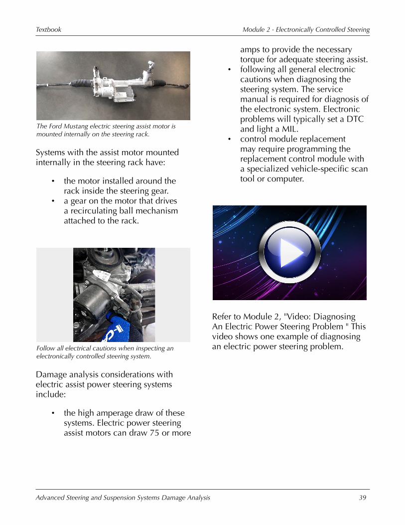
The�Ford�Mustang�electric�steering�assist�motor�ismounted�internally�on�the�steering�rack.
Systems�with�the�assist�motor�mountedinternally�in�the�steering�rack�have:
• the�motor�installed�around�therack�inside�the�steering�gear.
• a�gear�on�the�motor�that�drivesa�recirculating�ball�mechanismattached�to�the�rack.
Follow�all�electrical�cautions�when�inspecting�anelectronically�controlled�steering�system.
Damage�analysis�considerations�withelectric�assist�power�steering�systemsinclude:
• the�high�amperage�draw�of�thesesystems.�Electric�power�steeringassist�motors�can�draw�75�or�more
amps�to�provide�the�necessarytorque�for�adequate�steering�assist.
• following�all�general�electroniccautions�when�diagnosing�thesteering�system.�The�servicemanual�is�required�for�diagnosis�ofthe�electronic�system.�Electronicproblems�will�typically�set�a�DTCand�light�a�MIL.
• control�module�replacementmay�require�programming�thereplacement�control�module�witha�specialized�vehicle-specific�scantool�or�computer.
Refer�to�Module�2,�"Video:�DiagnosingAn�Electric�Power�Steering�Problem�"�Thisvideo�shows�one�example�of�diagnosingan�electric�power�steering�problem.
Module�2�-�Electronically�Controlled�SteeringTextbook
Advanced�Steering�and�Suspension�Systems�Damage�Analysis 40
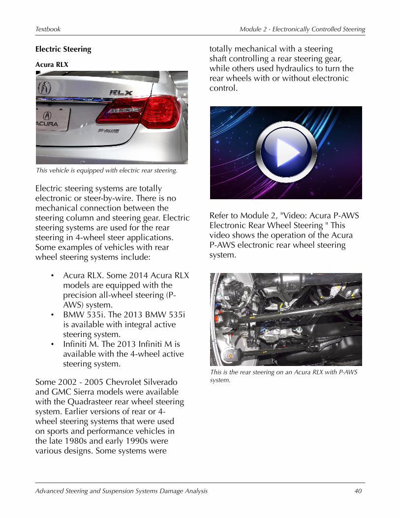
Electric�Steering
Acura�RLX
This�vehicle�is�equipped�with�electric�rear�steering.
Electric�steering�systems�are�totallyelectronic�or�steer-by-wire.�There�is�nomechanical�connection�between�thesteering�column�and�steering�gear.�Electricsteering�systems�are�used�for�the�rearsteering�in�4-wheel�steer�applications.Some�examples�of�vehicles�with�rearwheel�steering�systems�include:
• Acura�RLX.�Some�2014�Acura�RLXmodels�are�equipped�with�theprecision�all-wheel�steering�(P-AWS)�system.
• BMW�535i.�The�2013�BMW�535iis�available�with�integral�activesteering�system.
• Infiniti�M.�The�2013�Infiniti�M�isavailable�with�the�4-wheel�activesteering�system.
Some�2002�-�2005�Chevrolet�Silveradoand�GMC�Sierra�models�were�availablewith�the�Quadrasteer�rear�wheel�steeringsystem.�Earlier�versions�of�rear�or�4-wheel�steering�systems�that�were�usedon�sports�and�performance�vehicles�inthe�late�1980s�and�early�1990s�werevarious�designs.�Some�systems�were
totally�mechanical�with�a�steeringshaft�controlling�a�rear�steering�gear,while�others�used�hydraulics�to�turn�therear�wheels�with�or�without�electroniccontrol.
Refer�to�Module�2,�"Video:�Acura�P-AWSElectronic�Rear�Wheel�Steering�"�Thisvideo�shows�the�operation�of�the�AcuraP-AWS�electronic�rear�wheel�steeringsystem.
This�is�the�rear�steering�on�an�Acura�RLX�with�P-AWSsystem.

Module�2�-�Electronically�Controlled�SteeringTextbook
Advanced�Steering�and�Suspension�Systems�Damage�Analysis 41
This�is�the�rear�steering�system�on�a�2010�InfinitiM35.
The�main�parts�of�an�electric�rear�steeringsystem�may�include:
• the�wheel�position�sensors.�Wheelposition�sensors�provide�theprimary�input�to�the�rear�steeringcontrol�module.�For�example,on�the�2014�Acura�RLX�P-AWSsystem,�an�electric�actuator�witha�toe�position�sensor�is�installedat�each�rear�wheel�between�thesteering�knuckle�and�subframe.
• a�steerable�rear�axle�assembly.�Therear�axle�assembly�is�similar�indesign�to�the�steerable�solid�frontaxle�used�on�some�4-wheel�drivevehicles.
• a�rear�steering�gear�assembly�oractuator.
• the�control�module�for�the�rearsteering�system.
• various�secondary�input�sensors.
This�illustration�shows�the�parts�of�an�Acura�P-AWSrear�steering�system.
The�main�and�secondary�inputs�tothe�control�module�of�electric�rearsteer�systems�in�a�typical�4-wheel�steerapplication�includes:
• vehicle�speed.• steering�wheel�position.• yaw�rate�and�lateral�acceleration
of�the�vehicle�body.�Yaw�rate�andlateral�acceleration�inputs�cancome�from�the�same�sensor.
• rear�wheel�position.�A�rear�wheelposition�sensor�on�the�rear�steeringgear�is�used�to�determine�theamount�in�degrees�and�directionthat�the�rear�wheels�are�turned.
Acura�RLX
This�is�the�actuator�on�a�Acura�RLX�with�P-AWS.

Module�2�-�Electronically�Controlled�SteeringTextbook
Advanced�Steering�and�Suspension�Systems�Damage�Analysis 42
When�analyzing�damage�on�vehicles�thathave�electric�rear�steering�systems:
• do�not�allow�the�jack�or�liftingarms�to�contact�the�rear�steeringgear�or�other�parts�of�the�systemwhen�lifting�the�vehicle.
• a�scan�tool�is�required�to�accessdiagnostic�trouble�codes�andto�perform�specific�repairprocedures.�For�example,�on�the2014�Acura�RLX�P-AWS�system,the�neutral�position�of�the�toesensors�must�be�relearned�usinga�Honda�specific�scan�tool�ifthe�control�unit�or�an�actuator�isreplaced.
• note�that�some�parts�may�bevulnerable�to�collision�damagefrom�a�wheel�hit.
KPI�Improvement�TipIdentify�required�tools�and�equipment�torun�diagnostics�and�repairs�or�the�need�tosublet�repairs.
Module�Wrap-Up
Topics�discussed�in�this�moduleincluded:
• different�electronic�steeringsystems.
• the�operation�of�computercontrolled�variable�assist�powersteering�systems.
• electronic�steering�system�parts.• diagnosing�problems�with
electronically�controlled�steeringsystems.
• cautions�when�analyzing�damageon�vehicles�with�electronicallycontrolled�steering�systems.
• electric rear�steering�systems.
Module�3�-Electronically
ControlledSuspension

This�page�is�intentionally�left�blank.
Module�3�-�Electronically�Controlled�SuspensionTextbook
Advanced�Steering�and�Suspension�Systems�Damage�Analysis 45
Types�Of�Electronic�Suspensions
Refer�to�"Video:�Learning�Objectives"�inthe�presentation.
The�learning�objectives�for�this�moduleinclude:
• identifying�the�different�types�ofelectronic�suspension�systems.
• explaining�the�operation�ofelectronic�suspension�systems.
• identifying�electronicallycontrolled�system�parts.
• identifying�damage�analysiscautions�with�electronicallycontrolled�suspension�systems.
• identifying�the�different�types�oftire�pressure�monitoring�systems.
• identifying�tire�pressuremonitoring�system�parts.
• identifying�damage�analysiscautions�with�tire�pressuremonitoring�systems.
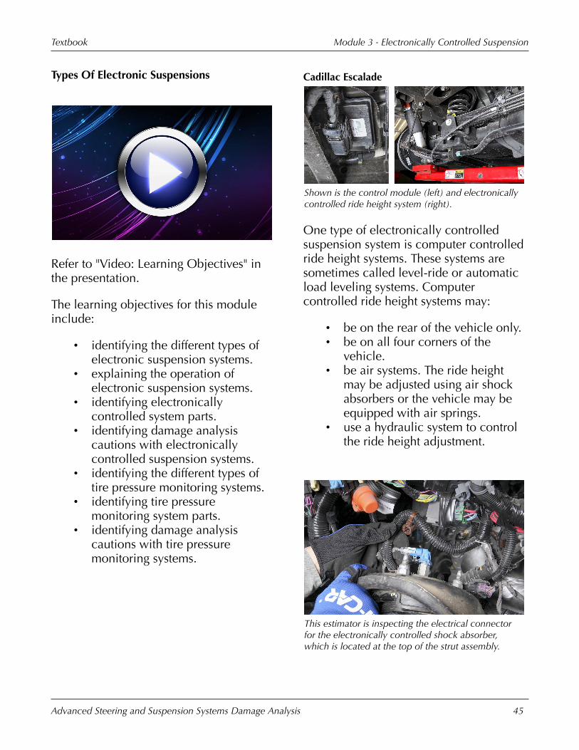
Cadillac�Escalade
Shown�is�the�control�module�(left)�and�electronicallycontrolled�ride�height�system�(right).
One�type�of�electronically�controlledsuspension�system�is�computer�controlledride�height�systems.�These�systems�aresometimes�called�level-ride�or�automaticload�leveling�systems.�Computercontrolled�ride�height�systems�may:
• be�on�the�rear�of�the�vehicle�only.• be�on�all�four�corners�of�the
vehicle.• be�air�systems.�The�ride�height
may�be�adjusted�using�air�shockabsorbers�or�the�vehicle�may�beequipped�with�air�springs.
• use�a hydraulic�system to�controlthe�ride�height�adjustment.
This�estimator�is�inspecting�the�electrical�connectorfor�the�electronically�controlled�shock�absorber,which�is�located�at�the�top�of�the�strut�assembly.

Module�3�-�Electronically�Controlled�SuspensionTextbook
Advanced�Steering�and�Suspension�Systems�Damage�Analysis 46
Another�type�of�electronically�controlledsuspension�is�computer�controlledvariable�shock�absorber�damping.Variable�shock�absorber�damping�may�becontrolled:
• mechanically�by�varying�theorifice�size�for�the�shock�absorberfluid.
• magnetically�by�varying�theviscosity�of�the�shock�absorberfluid.�The�fluid�orifice�size�remainsconstant�in�these�systems.
Cadillac�Escalade
This�strut�has�both�an�electrical�connector�for�shockabsorber�damping�and�an�air�line�for�ride�heightcontrol.
Vehicles�with�electronically�controlledsuspensions�may�have�combinationsystems.�Combination�systems:
• have�computer�control�of�bothride�height�and�shock�absorberdamping.
• may�have�air�springs�and�separatecomputer�controlled�variabledampers.
• may�use�computer�controlleddampers�to�adjust�both�the�rideheight�and�handling�characteristicsof�the�vehicle.�Dampers�in�thesesystems�may�be�hydraulic�strutswith�air�bladders�built�in�forsprings�or�be�totally�hydraulic�forboth�suspension�damping�and�rideheight.
This�illustration�shows�the�main�parts�of�a�semi-activesuspension�system.
Semi-active�suspension�systems:
• typically�consist�of�computercontrolled�variable�dampers�thatrespond�to�up-and-down�bodymotion�inputs�to�read�the�roadsurface.
• react�to�the�first�bounce�orsuspension�deflection�to�controlthe�second�bounce�or�deflection.They�are�not�active�but�ratherreactive.�Semi-active�systems�donot�directly�control�suspensiondeflection,�they�indirectly�controlit�by�altering�the�firmness�of�theshock�absorber�damping.

Module�3�-�Electronically�Controlled�SuspensionTextbook
Advanced�Steering�and�Suspension�Systems�Damage�Analysis 47
Cadillac�Escalade
The�suspension�system�on�this�vehicle�has�a�varietyof�complex�parts�used�to�control�suspensiondeflection.
Full-active�suspension�systems�are:
• more�complex�than�semi-activesystems.
• combination�systems�that�controlboth�ride�height�and�shockabsorber�damping.
• active�rather�than�reactive.They�control�the�first�bounce�ordeflection�by�pushing�the�wheelinto�the�dip�to�keep�the�vehiclelevel.�Full-active�systems�directlycontrol�the�deflection�of�thesuspension�and�hold�the�bodylevel�by�varying�both�damper�andspring�rates.
The�electrical�connector�at�the�top�of�the�strutindicates�the�presence�of�an�electronically�controlledsuspension�system.
The�presence�of�electronically�controlledsuspension�systems�is�typically�not�notedby�emblems�or�other�highly�visiblelabeling�on�the�vehicle.�To�determine�if�avehicle�is�equipped�with�an�electronicallycontrolled�suspension�system:
• perform�a�thorough�visualinspection�of�the�suspensionsystem.�Look�for�wiring�connectedto�suspension�parts,�such�as�shockabsorbers�or�struts.�Look�for�thepresence�of�air�or�hydraulic�fluidlines�to�the�shock�absorbers,struts,�or�springs.�Check�forthe�presence�of�a�MIL�for�anelectronic�suspension�systemwhen�the ignition�is�first�turnedON.�Look�for�switches�on�thedash�or�console�for�manualcontrol�of�electronic�suspensionsystems.�Systems�may�have�anON�/�OFF�switch,�a�switch�forsport�or�comfort�damper�settings,or�a�switch�for�control�of�vehicleheight.�Visually�identify�parts�thatwould�indicate�the�presence�ofspecific�electronic�or�electronic�/hydraulic�systems.

Module�3�-�Electronically�Controlled�SuspensionTextbook
Advanced�Steering�and�Suspension�Systems�Damage�Analysis 48
• use�the�information�located�onthe�option�label�or�tag�that�islocated�on�many�vehicles.�Thedealership�parts�departmentcan�provide�information�on�thedecoding�of�the�option�tag�todetermine�if�an�electronicallycontrolled�suspension�system�is�onthe�vehicle.
• use�a�VIN-driven�parts�orderingsystem.
KPI�Improvement�TipIdentify�the�need�to�disable thesuspension system�before�lifting�thevehicle.
Be�aware�that�initialization�/�programmingprocedures�may�be�required�on�somesystems�to�enable�electronic�assist�/operation.
Air�Shock�Absorber�Height�Control�Systems
This�illustration�shows�the�main�parts�of�an�air�shockabsorber�rear�height�control�system.
The�simplest�type�of�height�control�systemis�the�air�shock�absorber�system.�Air�shockabsorber�systems�only�control�the�heightat�the�rear�of�the�vehicle.�Typical�parts
of�an�air�shock�absorber�height�controlsystem�include:
• the�rear�air�shock�absorbers.Typical�air�shock�absorbers�usedin�rear�height�control�systems�havean�internal�air�chamber�that�airpressure�is�added�to�or�removedfrom�to�control�the�vehicle�height.The�damping�function�of�theshock�absorber�works�like�aconventional�shock�absorber.�Theair�shock�absorbers�do�not�act�assprings�for�the�vehicle,�but�ratherare�used�to�assist�the�springs�inholding�the�vehicle�level�withheavy�loads.
• an�air�compressor�with�a�drierto�remove�moisture�from�the�air.Depending�on�the�vehicle,�aircompressors�may�be�located�in�thefront�or�rear�of�the�vehicle.
• the�air�lines�from�the�compressorto�the�shock�absorbers.
• an�exhaust�valve�to�allow�airto�be�removed�from�the�shockabsorbers.�The�exhaust�valveis�typically�built�into�the�aircompressor.
• height�sensors�that�monitor�theride�height�of�the�vehicle.
• a�control�module.�Some�rear-onlyair�shock�absorber�systems�havea�combination�height�sensor�andcontrol�module�assembly.

Module�3�-�Electronically�Controlled�SuspensionTextbook
Advanced�Steering�and�Suspension�Systems�Damage�Analysis 49
This�illustration�shows�a�cutaway�view�of�a�typicalair�shock�absorber�from�a�rear-only�height�controlsystem.
Rear�air�shock�absorber�based�heightcontrol�systems:
• control�the�ride�height�by�eitheradding�or�removing�air�from�theshock�absorber�air�chamber.
• are�controlled�by�the�rear�heightsensor�and�control�module.�Theheight�sensor�determines�rear�rideheight�and�either�instructs�the�aircompressor�to�run�or�the�exhaustvalve�to�open.
• typically�have�delayed�activationto�avoid�having�the�compressorrun�in�response�to�temporarychanges�in�ride�height.
This�auto�physical�damage�appraiser�is�inspecting�therear�air�shock�absorber�for�damage.
Common�types�of�collision�damage�to�rearair�shock�absorber�height�control�systemsinclude:
• bent�shock�absorbers.• cut�or�kinked�plastic�air�lines.• damaged�sensors�or�control
modules.�Sensors�may�bephysically�damaged�or�misaligned,causing�improper�operation�of�thesystem.
• cut�wiring�or�smashed�connectors.• a�damaged�air�compressor.�Air
compressors�may�be�physicallydamaged�or�be�inoperative�due�toelectrical�damage.
Module�3�-�Electronically�Controlled�SuspensionTextbook
Advanced�Steering�and�Suspension�Systems�Damage�Analysis 50
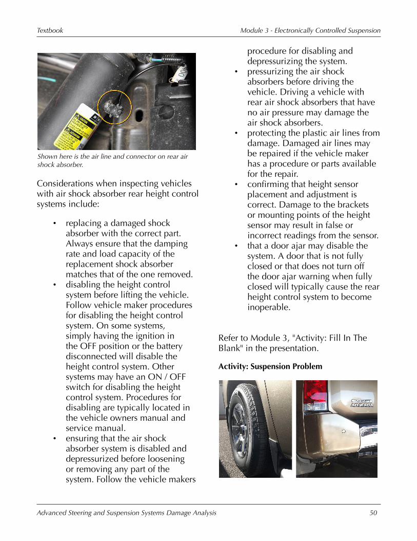
Shown�here�is�the�air�line�and�connector�on�rear�airshock�absorber.
Considerations�when�inspecting�vehicleswith�air�shock�absorber�rear�height�controlsystems�include:
• replacing�a�damaged�shockabsorber�with�the�correct�part.Always�ensure�that�the�dampingrate�and�load�capacity�of�thereplacement�shock�absorbermatches�that�of�the�one�removed.
• disabling�the�height�controlsystem�before�lifting�the�vehicle.Follow�vehicle�maker�proceduresfor�disabling�the�height�controlsystem.�On�some�systems,simply�having�the ignition�inthe�OFF�position�or�the�batterydisconnected�will�disable�theheight�control�system.�Othersystems�may�have�an�ON�/�OFFswitch�for�disabling�the�heightcontrol�system.�Procedures�fordisabling�are�typically�located�inthe�vehicle�owners�manual�andservice�manual.
• ensuring�that�the�air�shockabsorber�system�is�disabled�anddepressurized�before�looseningor�removing�any�part�of�thesystem.�Follow�the�vehicle�makers
procedure�for�disabling�anddepressurizing�the�system.
• pressurizing�the�air�shockabsorbers�before�driving�thevehicle.�Driving�a�vehicle�withrear�air�shock�absorbers�that�haveno�air�pressure�may�damage�theair�shock�absorbers.
• protecting�the�plastic�air�lines�fromdamage.�Damaged�air�lines�maybe�repaired�if�the�vehicle�makerhas�a�procedure�or�parts�availablefor�the�repair.
• confirming�that�height�sensorplacement�and�adjustment�iscorrect.�Damage�to�the�bracketsor�mounting�points�of�the�heightsensor�may�result�in�false�orincorrect�readings�from�the�sensor.
• that�a�door�ajar�may�disable�thesystem.�A�door�that�is�not�fullyclosed�or�that�does�not�turn�offthe�door�ajar�warning�when�fullyclosed�will�typically�cause�the�rearheight�control�system�to�becomeinoperable.
Refer�to�Module�3,�"Activity:�Fill�In�TheBlank"�in�the�presentation.
Activity:�Suspension�Problem

Module�3�-�Electronically�Controlled�SuspensionTextbook
Advanced�Steering�and�Suspension�Systems�Damage�Analysis 51
Refer�to�Module�3,�"Activity:�SuspensionProblem"�in�the�presentation.�This�activitypresents�one�example�of�why�a�thoroughinspection�is�important�when�analyzingdamage�on�a�vehicle�with�an�advancedsuspension�system.
Load�Leveling�/�Self-Leveling�SuspensionSystems
This�illustration�shows�the�main�parts�of�a�typicalfour�corner�electronic�air�spring�height�controlsystem.
Another�form�of�vehicle�height�controlsystem�uses�air�springs�with�conventionalshock�absorbers.�These�systems�may�be�onthe�rear�only�or�both�the�front�and�rear�ofthe�vehicle.�Typical�parts�of�an�air�springheight�control�system�include:
• air�springs�or�air�struts.�Systemsmay�have�separate�air�springs�andshock�absorbers�or�be�equippedwith�air�struts,�which�are�similarto�conventional�struts�exceptthe�spring�is�replaced�by�anair�bladder.�Unlike�air�shockabsorbers�that�assist�the�springs�insupporting�the�vehicle,�air�springsor�struts�completely�replace�theconventional�springs.
• an�air�compressor�with�a�drierto�remove�moisture�from�thecompressed�air�and�air�lines�fromthe�compressor�to�the�springs.
The�air�lines�are�typically�made�ofplastic.
• control�valves.�Systems�with�airsprings�at�all�four�wheels�havecontrol�valves�to�control�thedistribution�of�compressed�air�tothe�proper�spring�or�springs.
• a�control�module.• sensors�to�input�signals�to�the
control�module.�Typical�inputsare�for�ride�height,�vehicle�speed,steering�angle,�and�vehicleacceleration.�Ride�height�maybe�measured�for�front�andrear�or�independently�at�eachwheel.�Acceleration�data�may�beprovided�both�front�and back�andlaterally.
This�is�the�ON�/�OFF�switch�for�an�electronic�airspring�height�control�system.
Air�spring�based�height�control�systems:
• may�have�a�manual�ON�/�OFFswitch.�The�systems�typically�mustbe�disabled�or�turned�off�whentowing�or�lifting�the�vehicle.
• have�a�control�module�thatreceives�inputs�from�varioussensors�and�calculates�the

Module�3�-�Electronically�Controlled�SuspensionTextbook
Advanced�Steering�and�Suspension�Systems�Damage�Analysis 52
required�output�to�the�aircompressor�and�controlvalves. This�keeps�the�ride�heightat�the�desired�level.
• have�control�valves�that�route�theair�from�the�compressor�to�theappropriate�air�spring.
• control�the�vehicle�height�byadding�or�removing�air�pressurefrom�the�air�springs.
Air�spring�height�control�systems�may�control�bothfront�and�rear�ride�height.
Air�spring�height�control�systems�may:
• control�both�front�and�rear�rideheight.�Both�springs�on�either�endmay�be�controlled�together�intandem,�allowing�for�adjustmentof�the�front�and�rear�ride�height.
• allow�each�corner�to�be�adjustedindependently.
• have�a�manual�selector�switch�forheight�adjustment.�Some�systemshave�a�switch�that�allows�the�rideheight�to�be�changed�to�suit�thedriving�conditions.�The�vehiclecan�be�raised�for�additionalground�clearance�when�driving�offroad,�or�lowered�when�driving�on
the�highway�or�when�parking�toaide�in�vehicle�entry�and�exit.
• be�speed�related.�Some�systemsare�designed�to�lower�the�vehicleat�speeds�above�a�certain�amountto�allow�for�greater�high�speedstability.�Four-wheel�drive�vehiclesthat�are�raised�for�off-road�drivingwill�typically�lower�automaticallyabove�a�certain�speed�to�reducethe�risk�of�rollover.
• only�operate�with�the ignitionin�the�ON�position.�Havingthe ignition�OFF�will�typicallydisable�the�height�control�system.
This�technician�is�pointing�out�a�small�tear�in�the�airbladder�of�a�rear�air�spring.
This�2012�Toyota�Sequoia�has�a�damaged�air�springand�air�spring�compressor.�Click�to�the�next�slide�tosee�these�off�the�vehicle.

Module�3�-�Electronically�Controlled�SuspensionTextbook
Advanced�Steering�and�Suspension�Systems�Damage�Analysis 53
The�damaged�air�spring�and�air�compressor�from�theprevious�slide�are�shown�here�off�the�vehicle.
Common�types�of�collision�damage�to�airspring�height�control�systems�include:
• bent�shock�absorbers.�Bent�shockabsorber�rods�may�cause�the�shockabsorber�to�bind�and�not�allow�thesuspension�to�deflect.
• cut�or�damaged�air�springs.Air�springs�are�typically�madeof�rubber�and�can�be�cut�orpunctured�by�sharp�metal�during�acollision.�Collision�forces�can�alsocompress�and�blow�out�air�springsresulting�in�a�loss�of�spring�force.
• air�line�damage.�Air�lines�aretypically�made�of�plastic�and�aresusceptible�to�damage�from�sharpmetal�or�kinks,�restricting�the�airflow.
• electrical�part�damage.• damage�to�height�sensors.�Height
sensors�may�sustain�physicaldamage.�Mounting�locationsor�brackets�may�be�bent�or�outof�position�causing�impropersensor�readings.�Height�sensorsmay�be�adjustable�and�could�beknocked�out�of�adjustment�duringa�collision.�Height�sensors�must
be�positioned�properly�in�order�tofunction�as�intended.
The�height�control�system�should�be�depressurizedbefore�lifting�the�vehicle.
Considerations�for�damage�analysis�of�airspring�height�control�systems�include:
• disabling�the�system�before�liftingthe�vehicle.�Follow�the�vehiclemakers�procedure�for�disablingthe�height�control�system�beforetowing�or�lifting�the�vehicle.�Somevehicles�have�ON�/�OFF�switches,others�simply�require�the ignitionbe�left�in�the�OFF�position.
• depressurizing�the�systembefore�loosening�or�replacingparts.�Follow�vehicle�makerrecommendations�for�thedepressurization�of�air�heightcontrol�systems.
• the�repair�of�damaged�air�lines.Repair�only�where�allowed�bythe�vehicle�maker�with�repairparts�designed�for�the�application.Ensure�the�proper�routing�of�airlines�during�replacement.�Protectair�lines�from�damage�during
Module�3�-�Electronically�Controlled�SuspensionTextbook
Advanced�Steering�and�Suspension�Systems�Damage�Analysis 54
repairs�by�shielding�them�fromheat�or�sharp�objects.
• understanding�that�having�adoor�ajar�will�typically�disableautomatic�height�control�systems.When�working�with�air�springheight�control�systems,�ensure�thatall�vehicle�doors�are�fully�closed.
• following�vehicle�makerrecommendations.�Whenchanging�air�springs�in�computercontrolled�height�control�systems,always�follow�the�vehicle�makersrecommendations�and�proceduresfor�repair.�Air�spring�replacementmay�require�specific�proceduresbe�followed�to�avoid�damaging�thespring�or�causing�personal�injury.Procedures�typically�require�thesuspension�to�be�loaded�beforeinflating�the�spring�and�the�springto�be�inflated�before�driving�ormoving�the�vehicle.
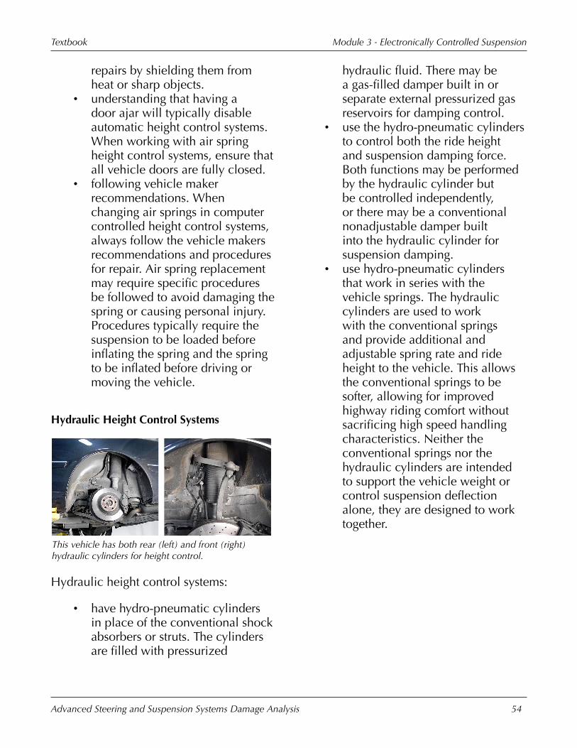
Hydraulic�Height�Control�Systems
This�vehicle�has�both�rear�(left)�and�front�(right)hydraulic�cylinders�for�height�control.
Hydraulic�height�control�systems:
• have�hydro-pneumatic�cylindersin�place�of�the�conventional�shockabsorbers�or�struts.�The�cylindersare�filled�with�pressurized
hydraulic�fluid.�There�may�bea�gas-filled�damper�built�in�orseparate�external�pressurized�gasreservoirs�for�damping�control.
• use�the�hydro-pneumatic�cylindersto�control�both�the�ride�heightand�suspension�damping�force.Both�functions�may�be�performedby�the�hydraulic�cylinder�butbe�controlled�independently,or�there�may�be�a�conventionalnonadjustable�damper�builtinto�the�hydraulic�cylinder�forsuspension�damping.
• use�hydro-pneumatic�cylindersthat�work�in�series�with�thevehicle�springs.�The�hydrauliccylinders�are�used�to workwith the�conventional�springsand�provide�additional�andadjustable�spring�rate�and�rideheight�to�the�vehicle.�This�allowsthe�conventional�springs�to�besofter,�allowing�for�improvedhighway�riding�comfort�withoutsacrificing�high�speed�handlingcharacteristics.�Neither�theconventional�springs�nor�thehydraulic�cylinders�are�intendedto�support�the�vehicle�weight�orcontrol�suspension�deflectionalone,�they�are�designed�to�worktogether.

Module�3�-�Electronically�Controlled�SuspensionTextbook
Advanced�Steering�and�Suspension�Systems�Damage�Analysis 55
This�illustration�shows�the�main�parts�of�a�typicalhydraulic�height�control�system.
The�basic�parts�of�a�hydraulic�heightcontrol�system�typically�include:
• a�hydraulic�fluid�pump.�The�powersteering�pump�is�typically�usedas�the�fluid�pump�for�hydraulicsuspension�systems.�The�pump�isa�tandem�pump�that�has�a�vanepump�used�for�power�steeringand�a�radial�pump�used�for�thesuspension�system.�The�twopumps�are�in�the�same�case�anddriven�by�a�common�shaft.�Bothsides�of�the�pump�typically�haveseparate�oil�feeds.�Fluid�pressuremay�be�as�high�as�13,100�kPa(1,900�psi).
• the�fluid�pressure�accumulatorthat�stores�hydraulic�fluid�underpressure.�The�accumulator�is�avessel�with�two�areas�separatedby�a�bladder.�One�side�containshydraulic�fluid�and�the�other�ahigh�pressure�gas�to�maintain�thepressure�on�the�hydraulic�fluid.There�may�be�more�than�oneaccumulator�in�some�systems.
• control�valves�or�actuators.The�control�valves�or�actuatorscontrol�the�flow�of�hydraulic�fluid
between�the�pump,�accumulator,and�cylinders.
• the�hydraulic�cylinders�thatreplace�the�conventional�shockabsorbers�or�struts�in�the�system.There�are�also�lines�to�carryhydraulic�fluid�between�thedifferent�parts�of�the�system.
• input�sensors�for�vehicle�rideheight,�speed,�and�acceleration;horizontally,�vertically,�andlaterally.
• a�control�module.• switches�and�other�basic�electrical
circuit�parts.
This�cutaway�illustration�shows�the�inside�of�a�typicalhydraulic�fluid�pressure�accumulator.
Hydraulic�height�control�systems:
• have�accumulators�that�storehydraulic�fluid�in�one�chamber,separated�from�high�pressure�gasin�another�chamber�by�a�rubberbladder.�The�system�may�havea�front�and�rear�accumulator�orseparate�accumulators�for�eachcorner�of�the�suspension.
• use�control�valves�to�control�theflow�of�hydraulic�fluid�between

Module�3�-�Electronically�Controlled�SuspensionTextbook
Advanced�Steering�and�Suspension�Systems�Damage�Analysis 56
the�accumulator�and�hydrauliccylinder.�When�the�controlmodule�calls�for�increased�rideheight�at�a�corner,�the�controlvalve�opens�a�valve�that�allowsfluid�to�flow�into�the�hydrauliccylinder�and�lift�the�vehicle.
• add�or�remove�hydraulic�fluidfrom�the�hydraulic�cylinders�ateach�corner�of�the�vehicle�toeither�raise�or�lower�ride�height.
The�accumulator�on�this�vehicle�is�damaged�and�willrequire�replacement.
Common�collision�damage�to�hydraulicheight�control�systems�include�damageto:
• fluid�pumps,�such�as�bent�pulleysor�shafts.�Fluid�leaks�may�resultfrom�damage�to�shaft�seals�orpump�housings.
• accumulators.• hydraulic�cylinder�rods.�Hydraulic
actuators�and�cylinders�can�alsohave�damaged�seals�resulting�influid�leaks�and�the�inability�tomaintain�ride�height.
• height�sensors.�Height�sensorsare�typically�located�on�or�near
suspension�system�parts�wherethey�can�be�easily�damaged.
• electrical�parts�including�cutwiring�or�smashed�connectors.
This�technician�is�loosening�a�bleeder�valve�on�afluid�line�from�a�hydraulic�height�control�system.
Considerations�with�damage�analysisof�hydraulic�height�control�systemsinclude:
• high�pressure.�Hydraulic�pressurecan�exceed�13,100�kPa�(1,900psi).�The�systems�must�bedepressurized�before�servicingany�hydraulic�system�parts.Accumulators�must�also�behandled�with�care�and�should notbe�repaired�if�damaged.�Neverhammer�or�weld�on�accumulatorsand�replace�them�if�there�are�anysigns�of�physical�damage.
• proper�alignment�and�adjustmentof�the�height�sensors.�The�heightsensors�supply�the�main�input�tothe�control�module.�A�misalignedor�out-of-adjustment�height�sensorwill�supply�the�control�modulewith�inaccurate�information�andcause�the�height�of�the�corner�to

Module�3�-�Electronically�Controlled�SuspensionTextbook
Advanced�Steering�and�Suspension�Systems�Damage�Analysis 57
be�incorrect.�Follow�vehicle�makerrecommendations�for�measuringand�adjusting�ride�height.
• following�the�general�cautions�andprocedures�for�electronic�systems.
These�fluid�lines�and�distribution�blocks�for�thehydraulic�height�control�system�are�located�wherethey�are�susceptible�to�damage�in�a�collision.
Additional�considerations�when�analyzingdamage�on�hydraulic�suspension�systemsinclude:
• using�the�correct�hydraulic�fluid.The�systems�typically�sharethe�fluid�pump�with�the�powersteering�system,�but�may�require�aspecific�fluid�for�proper�operation.Always�use�the�specified�fluidwhen�adding�fluid�to�the�system.
• fluid�lines�are�not�repairable�andmust�be�replaced�if�damaged.�Dueto�the�high�pressures,�fluid�linesshould not�be�repaired.�Ensurethat�the�fluid�lines�are�properlyrouted�if�any�are�replaced.�Fluidlines�should�also�be�checked�forkinks�and�leaks�wherever�repairshave�been�made�or�in�the�area�ofcollision�damage.
• using�a�scan�tool.�When�workingon�hydraulic�suspension�systems,scan�tools�may�be�required�fordiagnosis�of�electronic�problemsand�for�service�procedures,�suchas�bleeding�air�from�the�hydraulicsystem�after�parts�are�replacedor�measuring�and�setting�rideheight.�Leak-checking�of�mostsystems�involves�using�a�vehicle-specific�scan�tool�to�open�andclose�valves,�pressurizing�variousparts�of�the�system,�and�lookingfor�fluid�leakage�in�parts�andconnections.
The�bleeder�valve�for�this�hydraulic�fluid�line�has�aprotective�rubber�cap.
When�diagnosing�damage�on�hydraulicsuspension�systems,�be�aware�that�somesystems�may�require�bleeding.�Bleedingthe�hydraulics�on�hydraulic�suspensionsystems:
• should�be�done�following�vehiclemaker�recommendations.
• is�typically�required�after�partsreplacement�or�disconnection�ofany�hydraulic�fluid�line.

Module�3�-�Electronically�Controlled�SuspensionTextbook
Advanced�Steering�and�Suspension�Systems�Damage�Analysis 58
• may�require�different�proceduresfor�different�parts�of�the�system.Some�parts�may�be�bled�byopening�a�bleeder�valve�similar�tothose�used�on�brake�calipers.
• may�require�vacuum�bleeding�onsome�parts�of�the�system.
• may�require�a�scan�tool.�Someparts�of�the�system�require�certainvalves�to�be�controlled�by�avehicle-specific�scan�tool�in�orderto�bleed�the�air.
Computer�Controlled�Dampers
The�computer�controlled�damper�on�this�strutassembly�has�the�fluid�control�valve�locatedexternally�at�the�bottom�of�the�strut.
Electronically�controlled�suspensiondampers�(shock�absorbers):
• are�the�main�parts�of�road�sensingsuspension�systems.
• vary�the�ride�and�handlingcharacteristics�of�the�vehicle.�Thisis�done by�altering�the�firmnessof�the�shock�absorber�damping�inresponse�to�various�sensor�inputs.
• are�considered�semi-activesuspension�systems�when�used
by�themselves�with�no�otherelectronic�suspension�control.
• may�be�part�of�a�fully�activesuspension�when�used�incombination�with�otherelectronically�controlledsuspension�systems.
This�illustration�shows�the�openings�in�the�shockabsorber�piston�that�control�fluid�flow�and�shockabsorber�damping�stiffness.
An�explanation�of�conventional�damperoperation�is�that:
• a�piston�on�the�end�of�the�damperrod�travels�in�a�cylinder�filled�withhydraulic�fluid.�The�cylinder�is�thedamper�body.
• orifices�or�openings�in�the�pistonallow�the�hydraulic�fluid�to�flowbetween�the�two�chambers�of�thecylinder.�The�size�of�the�openingsin�the�piston�control�the�amountand�speed�of�fluid�flow�betweenchambers�in�the�damper�body,and�consequently�the�speed�atwhich�the�piston�can�travel.�Theopening�size�is�what�determinesthe�firmness�of�the�damper.

Module�3�-�Electronically�Controlled�SuspensionTextbook
Advanced�Steering�and�Suspension�Systems�Damage�Analysis 59
Refer�to�Module�2,�"Video:�ConventionalDamper�Operation"�This�animationshows�the�operation�of�a�conventionalsuspension�damper�or�shock�absorber.
These�illustrations�show�how�a�typical�variabledamper�varies�the�resistance�to�movement�byopening�and�closing�internal�valves.
The�firmness�or�resistance�to�movementthat�a�damper�in�electronically�controlledsuspension�systems�has�is�controlled�by�acontrol�module�that:
• uses�a�variety�of�input�signalsto�determine�the�appropriatedamper�stiffness�for�current�roadand�driving�conditions.�Theseinput�signals�may�be�supplied�byindividual�sensors�and�by�controlmodules�for�other�vehicle�systems.
• can�be�controlled�by�varying�theopening�size�that�the�hydraulicfluid�flows�through�or�by�varyingthe�viscosity�of�the�fluid.
The�parts�that�supply�inputs�to�the�control�modulefor�an�electronically�controlled�suspension�dampingsystem�include�(left�to�right)�a�steering�wheelposition�sensor,�vehicle�height�sensor,�and�lateralacceleration�sensor.
Typical�inputs�to�control�modules�forcomputer�controlled�suspension�dampersinclude:
• vehicle�height.�Vehicle�heightsensors�measure�the�wheel-to-body�position�and�input�signalson�up�and�down�movement�of�thevehicle�body.�Height�sensors�aretypically�located�at�each�corner�ofthe�vehicle�with�an�arm�connectedto�a�movable�suspension�part.
• vehicle�acceleration.�Vehicleacceleration�is�monitored�in�threeplanes,�longitudinally,�laterally,and�vertically.�Longitudinalacceleration�is�the�front�and rearacceleration�of�the�vehiclecaused�by�throttle�and�brakingforces.�Lateral�acceleration�isthe�sideways�acceleration�of�the
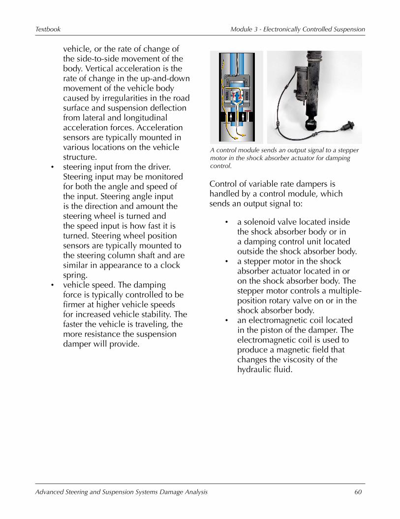
Module�3�-�Electronically�Controlled�SuspensionTextbook
Advanced�Steering�and�Suspension�Systems�Damage�Analysis 60
vehicle,�or�the�rate�of�change�ofthe�side-to-side�movement�of�thebody.�Vertical�acceleration�is�therate�of�change�in�the�up-and-downmovement�of�the�vehicle�bodycaused�by�irregularities�in�the�roadsurface�and�suspension�deflectionfrom�lateral�and�longitudinalacceleration�forces.�Accelerationsensors�are�typically�mounted�invarious�locations�on�the�vehiclestructure.
• steering�input�from�the�driver.Steering�input�may�be�monitoredfor�both�the�angle�and�speed�ofthe�input.�Steering�angle�inputis�the�direction�and�amount�thesteering�wheel�is�turned�andthe�speed�input�is�how�fast�it�isturned.�Steering�wheel�positionsensors�are�typically�mounted�tothe�steering�column�shaft�and�aresimilar�in�appearance�to�a�clockspring.
• vehicle�speed.�The�dampingforce�is�typically�controlled�to�befirmer�at�higher�vehicle�speedsfor�increased�vehicle�stability.�Thefaster�the�vehicle�is�traveling,�themore�resistance�the�suspensiondamper�will�provide.
A�control�module�sends�an�output�signal�to�a�steppermotor�in�the�shock�absorber�actuator�for�dampingcontrol.
Control�of�variable�rate�dampers�ishandled�by�a�control�module,�whichsends�an�output�signal�to:
• a�solenoid�valve�located�insidethe�shock�absorber�body�or�ina�damping�control�unit�locatedoutside�the�shock�absorber�body.
• a�stepper�motor�in�the�shockabsorber�actuator�located�in�oron�the�shock�absorber�body.�Thestepper�motor�controls�a�multiple-position�rotary�valve�on�or�in�theshock�absorber�body.
• an�electromagnetic�coil�locatedin�the�piston�of�the�damper.�Theelectromagnetic�coil�is�used�toproduce�a�magnetic�field�thatchanges�the�viscosity�of�thehydraulic�fluid.

Module�3�-�Electronically�Controlled�SuspensionTextbook
Advanced�Steering�and�Suspension�Systems�Damage�Analysis 61
This�illustration�shows�how�an�internal�valvedvariable�damper�operates.
The�operation�of�computer�controlledsuspension�dampers�may�be�electricallycontrolled�by�a�solenoid�or�steppermotor. These�use internal�actuators�orvalves�located�in�the�damper�body�orpiston�to�control�the�flow�of�the�fluid�inthe�shock�absorber.
Valves�are�opened�or�closed�to�varythe�opening�size�and�resistance�to�fluidflow�inside�the�shock�absorber.�Moreresistance�to�flow�produces�a�firmersuspension�damping�force�and�lessresistance�produces�a�softer�dampingforce.
This�shock�absorber�has�an�external�damping�valveto�control�the�firmness�of�its�damping�force.
The�operation�of�computer�controlledsuspension�dampers�may�be�electricallycontrolled�by�a�solenoid�or�stepper�motorlocated�in�external�damping�valves�onsome�systems.�The�shock�absorber�mayhave�an�external�damping�unit�connectedto�it�that,�through�a�series�of�valves,controls�the�firmness�of�the�damping�forceof�the�shock�absorber.�The�hydraulic�fluidin�the�shock�absorber�travels�through�thedamping�control�unit�as�it�is�forced�fromthe�upper�shock�absorber�chamber�intothe�lower�chamber.
External�damping�units�are�used�to�allowfor�more�valves�than�would�fit�internallyin�the�shock�absorber�body.�The�additionalvalves�allow�a�greater�degree�of�tuningflexibility�due�to�the�increase�in�thenumber�of�damping�force�settings.
This�magnetically�controlled�shock�absorber�lookslike�a�typical�conventional�shock�absorber�from�thisangle.
Magnetically�controlled�variable�dampersystems:
• include�MagneRide.�Othernames�for�the�system�includeMagneto-Rheological�RealTime�Damping�(MRRTD)�or

Module�3�-�Electronically�Controlled�SuspensionTextbook
Advanced�Steering�and�Suspension�Systems�Damage�Analysis 62
Magnetic�Ride�Control.�The�2013Chevrolet�Corvette�is�one�exampleof�a�vehicle�with�the�MRRTDelectronic�suspension�system.
• have�constant�shock�absorbervalving�with�a�variable�viscosityfluid.�These�systems�controlfirmness�by�varying�the�viscosity�ofthe�fluid�inside�the�shock�absorberinstead�of�varying�the�opening�sizethat�the�fluid�is�forced�through.The�thicker�the�fluid,�the�harderit�will�be�to�force�through�theopenings�in�the�piston�and�theslower�the�piston�will�travel.
• are�less�complicated�and�havefewer�parts�than�valve-basedvariable�dampers.
• have�a�faster�response�rate�thantypical�valve-based�variabledampers.
• have�dampers�that�are�similar�inconstruction�to�a�conventionalsuspension�system.�The�shockabsorbers�are�a�single�tube,�gas-filled�unit�with�fixed�nonvariablevalves�for�fluid�control.
This�illustration�shows�how�the�presence�of�amagnetic�field�aligns�the�magnetic�particles�in�themagneto-rheological�fluid�and�increases�the�fluidviscosity.
MagneRide�suspension�systems�use�aspecial�fluid�to�control�the�damping�forcefirmness.�The�fluid�has�special�randomlysuspended�magnetic�particles.
In�the�presence�of�a�magnetic�field,the�particles�align�themselves�with�themagnetic�field�lines�and�each�other.This�raises�the�viscosity�of�the�fluid.�Thefluid�has�an�unlimited�range�of�viscositydepending�on�the�strength�of�the�magneticfield�in�which�it�is�placed.�It�can�go�froma�fluid-like�state�when�no�magnetic�fieldis�present,�to�an�almost�plastic-like�statein�the�presence�of�a�strong�magnetic�field.The�magnetic�field�is�produced�by�anelectromagnet�located�on�the�piston�of�thedamper.
This�variable�damper�air�strut�has�been�bent�in�acollision�and�requires�replacement.
Considerations�for�damage�analysis�oncomputer�controlled�suspension�dampingsystems�include:
• they�are�subject�to�the�sametypes�of�mechanical�damage�asconventional�suspension�dampers.
• removal�and�replacementprocedures,�which�are�the�same�asconventional�suspension�dampers
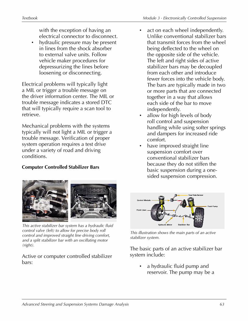
Module�3�-�Electronically�Controlled�SuspensionTextbook
Advanced�Steering�and�Suspension�Systems�Damage�Analysis 63
with�the�exception�of�having�anelectrical�connector�to�disconnect.
• hydraulic�pressure�may�be�presentin�lines�from�the�shock�absorberto�external�valve�units.�Followvehicle�maker�procedures�fordepressurizing�the�lines�beforeloosening�or�disconnecting.
Electrical�problems�will�typically�lighta�MIL�or�trigger�a�trouble�message�onthe�driver�information�center.�The�MIL�ortrouble�message�indicates�a�stored�DTCthat�will�typically�require�a�scan�tool�toretrieve.
Mechanical�problems�with�the�systemstypically�will�not�light�a�MIL�or�trigger�atrouble�message.�Verification�of�propersystem�operation�requires�a�test�driveunder�a�variety�of�road�and�drivingconditions.
Computer�Controlled�Stabilizer�Bars
This�active�stabilizer�bar�system�has�a�hydraulic�fluidcontrol�valve�(left)�to�allow�for�precise�body�rollcontrol�and�improved�straight�line�driving�comfort,and�a�split�stabilizer�bar�with�an�oscillating�motor(right).
Active�or�computer�controlled�stabilizerbars:
• act�on�each�wheel�independently.Unlike�conventional�stabilizer�barsthat�transmit�forces�from�the�wheelbeing�deflected�to�the�wheel�onthe�opposite�side�of�the�vehicle.The�left�and�right�sides�of�activestabilizer�bars�may�be�decoupledfrom�each�other�and�introducefewer�forces�into�the�vehicle�body.The�bars�are�typically�made�in�twoor�more�parts�that�are�connectedtogether�in�a�way�that�allowseach�side�of�the�bar�to�moveindependently.
• allow�for�high�levels�of�bodyroll�control�and�suspensionhandling�while�using�softer�springsand�dampers�for�increased�ridecomfort.
• have�improved�straight�linesuspension�comfort�overconventional�stabilizer�barsbecause�they�do not�stiffen�thebasic�suspension�during�a�one-sided�suspension�compression.
This�illustration�shows�the�main�parts�of�an�activestabilizer�system.
The�basic�parts�of�an�active�stabilizer�barsystem�include:
• a�hydraulic�fluid�pump�andreservoir.�The�pump�may�be�a

Module�3�-�Electronically�Controlled�SuspensionTextbook
Advanced�Steering�and�Suspension�Systems�Damage�Analysis 64
separate�radial�design�pump�forthe�stabilizer�bar�or�the�systemmay�share�the�fluid�pump�withthe�power�steering�system.�Thistandem�pump�has�a�vane�pumpfor�power�steering�and�a�radialpump�for�the�suspension�systemthat�are�driven�off�the�same�shaft.
• a�control�module.• control�valves�for�control�of�the
hydraulic�fluid�flow.• high�pressure�hydraulic�fluid�lines.• lateral�acceleration�sensors�to
measure�the�yaw�rate,�pitch,�androll�of�the�vehicle�body.
• hydraulic�motors�or�actuators�thatare�used�to�lock�stabilizer�barhalves�together�or�connect�the�barto�the�vehicle�suspension.
• stabilizer�bars.�Each�axle�mayhave�a�stabilizer�bar�that�is�madeof�two�parts�or�it�may�have�asolid�bar�that�is�connected�to�thesuspension�on�one�side�with�avariable�hydraulic�linear�actuator.
This�is�the�oscillating�motor�that�connects�the�twohalves�of�the�active�stabilizer�bar�on�a�BMW�745iequipped�with�the�optional�dynamic�drive�system.
When�a�vehicle�that�is�equipped�withactive�stabilizer�bars�goes�around�a�corneror�curve:
• the�lateral�acceleration�or�yawrate�sensors�detect�the�body�rolland�send�a�signal�to�the�controlmodule.
• the�control�module�acts�on�thevalve�blocks�to�supply�pressurizedhydraulic�fluid�to�the�correctside�of�the�oscillating�motor�orhydraulic�actuator.�The�oscillatingmotor,�or�actuator,�then�twists�thestabilizer�bar�halves�in�oppositedirections�to�counteract�the�rollof�the�vehicle�body�over�thesuspension.�This�action�keeps�thebody�level�and�balances�out�theforces�between�the�tires�and�theroad,�improving�vehicle�handling.The�hydraulic�oscillating�motorsare�split�chamber�hydraulicallycontrolled�rotary�actuators.One�half�of�the�stabilizer�bar�isattached�to�the�oscillating�motorshaft�and�the�other�half�to�themotor�housing.�As�the�shaft�twistsone�way,�the�housing�twists�theother.�Systems�using�a�linearactuator�apply�pressure�to�oneend�of�the�stabilizer�bar�whiletwisting�the�other�bar�half�in�thedirection�that�applies�pressure�inthe�opposite�direction�to�the�wheelon�the�opposite�side.
• the�reaction�of�the�oscillatingmotors�or�actuators�on�thestabilizer�bar�halves�is�speedsensitive.�At�low�speeds,�thesystem�is�designed�to�provideneutral�handling�and�lower�turning
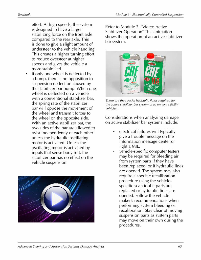
Module�3�-�Electronically�Controlled�SuspensionTextbook
Advanced�Steering�and�Suspension�Systems�Damage�Analysis 65
effort.�At�high�speeds,�the�systemis�designed�to�have�a�largerstabilizing�force�on�the�front�axlecompared�to�the�rear�axle.�Thisis�done�to�give�a�slight�amount�ofundersteer�to�the�vehicle�handling.This�creates�a�higher�turning�effortto�reduce�oversteer�at�higherspeeds�and�gives�the�vehicle�amore�stable�feel.
• if�only�one�wheel�is�deflected�bya�bump,�there�is�no�opposition�tosuspension�deflection�caused�bythe�stabilizer�bar�bump.�When�onewheel�is�deflected�on�a�vehiclewith�a�conventional�stabilizer�bar,the�spring�rate�of�the�stabilizerbar�will�oppose�the�movement�ofthe�wheel�and�transmit�forces�tothe�wheel�on�the�opposite�side.With�an�active�stabilizer�bar,�thetwo�sides�of�the�bar�are�allowed�totwist�independently�of�each�otherunless�the�hydraulic�oscillatingmotor�is�activated.�Unless�theoscillating�motor�is�activated�byinputs�that�sense�body�roll,�thestabilizer�bar�has�no�effect�on�thevehicle�suspension.
Refer�to�Module�2,�"Video:�ActiveStabilizer�Operation"�This�animationshows�the�operation�of�an�active�stabilizerbar�system.
These�are�the�special�hydraulic�fluids�required�forthe�active�stabilizer�bar�system�used�on�some�BMWvehicles.
Considerations�when�analyzing�damageon�active�stabilizer�bar�systems�include:
• electrical�failures�will�typicallygive�a�trouble�message�on�theinformation�message�center�orlight�a�MIL.
• vehicle-specific�computer�testersmay�be�required�for�bleeding�airfrom�system�parts�if�they�havebeen�replaced,�or�if�hydraulic�linesare�opened.�The�system�may�alsorequire�a�specific�recalibrationprocedure�using�the�vehicle-specific�scan�tool�if�parts�arereplaced�or�hydraulic�lines�areopened.�Follow�the�vehiclemaker’s�recommendations�whenperforming�system�bleeding�orrecalibration.�Stay�clear�of�movingsuspension�parts�as�system�partsmay�move�on�their�own�during�theprocedures.

Module�3�-�Electronically�Controlled�SuspensionTextbook
Advanced�Steering�and�Suspension�Systems�Damage�Analysis 66
• the�use�of�specific�hydraulic�fluidsare�required�for�proper�systemoperation.�Use�the�fluid�specifiedby�the�vehicle�maker�when�addingfluid.�Any�disconnected�hydrauliclines�should�be�covered�to�sealthem�from�contamination.
• correct�positioning�of�the�lateralacceleration�sensors�is�criticalto�proper�system�operation.Damaged�brackets�or�mountingpoints�for�the�sensors�may�renderthe�system�inoperable.�The�sensorsare�also�sensitive�to�shock�loadsand�may�require�replacement�ifdropped�or�shocked�in�any�way.�Toavoid�damage,�remove�the�sensorsfrom�areas�where�air�chisels�willbe�used�or�stress-relieving�will�bedone.
KPI�Improvement�TipThere�may�be�special�material�/equipment�requirements�for�somesystems.�For�example,�some�systemsrequire�specialized�high-pressure�serviceequipment.
Tire�Pressure�Monitors
Ford�Explorer
A�tire�pressure�monitoring�system�would�detectthis�low�tire�and�warn�the�driver�that�a�tire�needschecking.
Tire�pressure�monitoring�systems(TPMS):
• warn�the�vehicle�driver�of�a�lowtire.�A�warning�lamp�on�the�dashor�message�on�the�informationmessage�center�is�used�to�alert�thedriver�of�a�low�tire.
• are�typically�one�of�two�differentbasic�designs.�Systems�may�be�anindirect�system,�which�calculatesa�pressure�difference�for�a�low�tireusing�the�ABS�system,�or�a�directsystem�which�measures�the�actualpressure�of�each�tire.

Module�3�-�Electronically�Controlled�SuspensionTextbook
Advanced�Steering�and�Suspension�Systems�Damage�Analysis 67
The�rolling�radius�method�used�by�indirect�tirepressure�monitoring�systems�detects�a�low�tire�bysensing�the�rotational�speed�difference�between�thelow�tire�and�the�other�tires.
Indirect�tire�pressure�monitoringsystems:
• use�the�anti-lock�brake�system(ABS)�control�module�and�sensorsto�operate.�No�new�or�addedsensors�or�electronics�are�used�inthe�system.
• detect�differences�in�tire�pressure.These�systems�do not�calculatethe�actual�pressure�in�the�tire,�butrather�warn�of�differences�betweenthe�pressures�of�the�tires.�A�lowtire�will�have�a�smaller�effectivediameter�and�will�roll�at�a�differentspeed�than�a�fully�inflated�tire.By�using�the�wheel�speed�sensorsof�the�ABS�system,�the�controlmodule�can�detect�that�a�tire�isrolling�at�a�different�speed�fromthe�other�tires.�A�drawback�to�thissystem�is�that�the�tire�air�pressuretypically�has�to�vary�by�about�25-�30%�before�a�low�tire�can�bedetected.
• typically�require�the�vehicle�tobe�driven�for�a�specific�driving
sequence�to�calculate�any�pressuredifferences.
This�is�the�warning�lamp�that�indicates�a�low�tire�onthis�vehicle.
Indirect�tire�pressure�monitoringsystems:
• will�not�detect�if�two�or�more�tiresare�low.�Because�they�only�detectpressure�differences,�they�cannotmake�a�determination�if�more�thanone�tire�is�low.
• require�a�recalibration�procedurewhen�the�diameter�of�the�tires�onthe�vehicle�is�changed.
• have�a�warning lamp�on�the�dashthat�warns�of�a�low�tire.�The�lampwill�not�indicate�which�tire�is�lowand�will�typically�require�resettingafter�the�pressure�difference�or�lowtire�is�repaired.
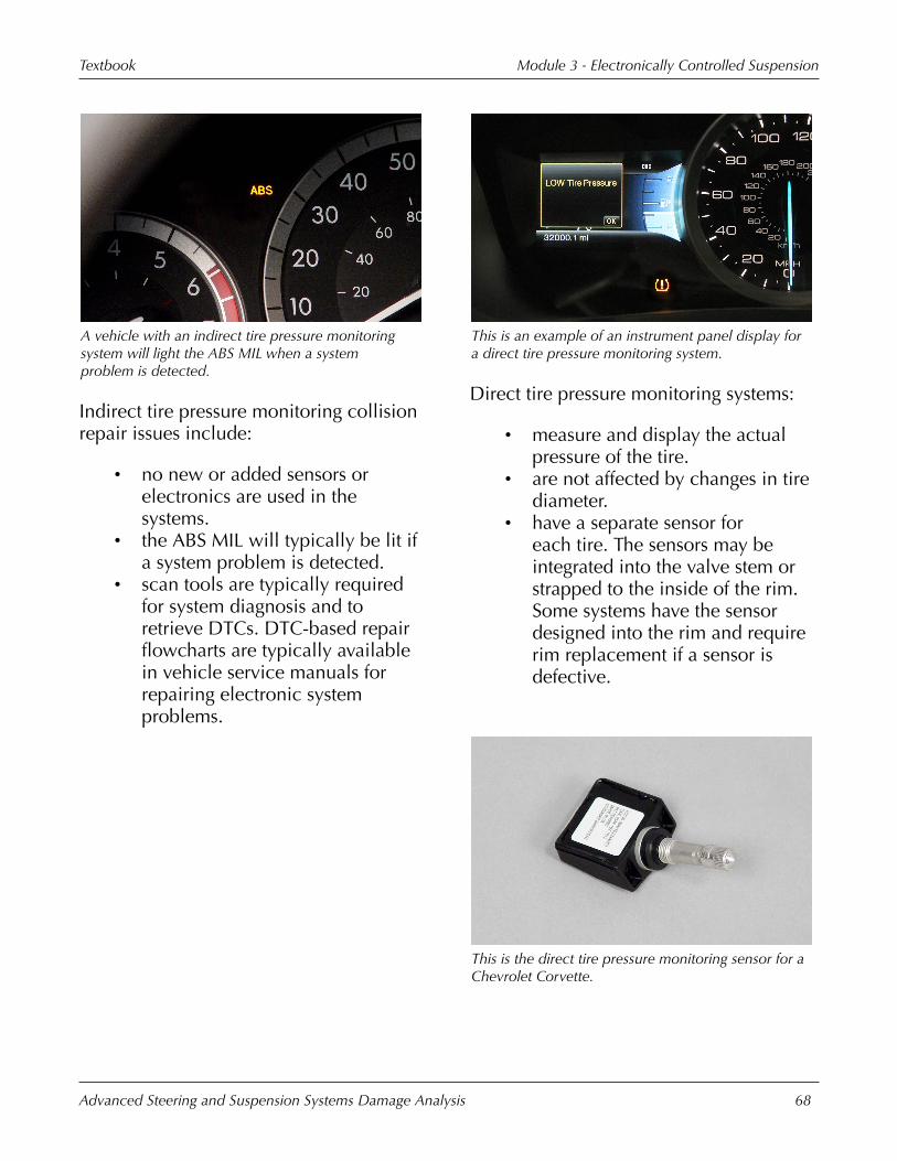
Module�3�-�Electronically�Controlled�SuspensionTextbook
Advanced�Steering�and�Suspension�Systems�Damage�Analysis 68
A�vehicle�with�an�indirect�tire�pressure�monitoringsystem�will�light�the�ABS�MIL�when�a�systemproblem�is�detected.
Indirect�tire�pressure�monitoring�collisionrepair�issues�include:
• no�new�or�added�sensors�orelectronics�are�used�in�thesystems.
• the�ABS�MIL�will�typically�be�lit�ifa�system�problem�is�detected.
• scan�tools�are�typically�requiredfor�system�diagnosis�and�toretrieve�DTCs.�DTC-based�repairflowcharts�are�typically�availablein�vehicle�service�manuals�forrepairing�electronic�systemproblems.
This�is�an�example�of�an�instrument�panel�display�fora�direct�tire�pressure�monitoring�system.
Direct�tire�pressure�monitoring�systems:
• measure�and�display�the�actualpressure�of�the�tire.
• are�not�affected�by�changes�in�tirediameter.
• have�a�separate�sensor�foreach�tire.�The�sensors�may�beintegrated�into�the�valve�stem�orstrapped�to�the�inside�of�the�rim.Some�systems�have�the�sensordesigned�into�the�rim�and�requirerim�replacement�if�a�sensor�isdefective.
This�is�the�direct�tire�pressure�monitoring�sensor�for�aChevrolet�Corvette.

Module�3�-�Electronically�Controlled�SuspensionTextbook
Advanced�Steering�and�Suspension�Systems�Damage�Analysis 69
Direct�tire�pressure�monitor�sensors:
• are�small�electronic�circuit�boardswith�a�silicon-based�pressuresensor�built�in.
• contain�a�radio�frequency�(RF)transmitter.
• have�a�built-in�battery.• contain�a�small�computer
processor�with�a�small�amount�ofread-only�memory�(ROM)�and�aclock�speed�of�less�than�4�MHz.
This�illustration�shows�the�radio�signals�sent�from�theindividual�tire�pressure�monitoring�sensors,�in�eachwheel,�to�the�control�module.
Direct�tire�pressure�monitors:
• typically�measure�both�thepressure�and�temperature�of�the�airin�the�tire.
• send�a�radio�signal�from�thesensor�in�the�tire�to�an�antennaor�receiver.�The�antenna�may�belocated�in�the�control�module,�orthere�may�be�separate�antennason�the�body�near�each�tire�that�arewired�into�the�control�module.
• indicate�a�low�tire�with�a�warninglamp�or�message�on�the�driverinformation�center.�On�somesystems,�high�air�pressure�mayalso�set�the�low�tire�indicator.
This�is�the�receiving�antenna�located�in�thewheelhouse�area�of�a�BMW�745i�with�a�direct�tirepressure�monitoring�system.
Repair�considerations�with�direct�tirepressure�monitoring�systems�include:
• checking�for�damaged�antennas�orwiring.�Receiving�antennas�maybe�located�in�areas�susceptible�tocollision�damage.�Check�antennasand�wiring�in�the�area�of�collisiondamage.�Repair�of�the�antennawiring�harness�is�typically�notrecommended.
• electronic�malfunctions�willtypically�require�a�scan�tool�fordiagnosis.
• replacing�damaged�sensors.Sensors�are not�repairable.�Thevalve�stem�core�and�cap�usedon�direct�tire�pressure�monitorsensors have�a�special�design�andfunction�as�the�sensor�antenna.Replacing�them�with�valve�stem

Module�3�-�Electronically�Controlled�SuspensionTextbook
Advanced�Steering�and�Suspension�Systems�Damage�Analysis 70
cores�and�caps�from�conventionalvalve�stems�may�cause�radio�signalinterference�and�cause�a�systemmalfunction.�Replace�the�sensor�ifthe�correct�valve�stem�core�or�capis�not�available.
• not�using�tire�sealers�in�tireswith�direct�tire�pressure�monitorsensors.�Tire�sealers�can�clogthe�pressure�sensor�and�cause�asystem�malfunction.
After�making�an�air�pressure�adjustment�to�thislow�tire,�the�technician�will�have�to�performan�initialization�procedure�on�the�tire�pressuremonitoring�system.
Other�issues�with�the�repair�of�vehicleswith�direct�tire�pressure�monitoringsystems�are�that�the�systems�typicallyrequire�an�initialization�procedure�after:
• tire�rotation�or�replacement.• tire�pressure�adjustments.• pressure�sensor�replacement.
Follow�the�vehicle�makers�proceduresfor�system�initialization�after�repairs.Initialization�or�reprogramming mayrequire�a�scan�tool�and�may�also�requireother�vehicle�specific�tools.
Some�Nissan�models,�such�as�the�2013Altima�and�Quest,�come�with�the�"Easy-Fill�Tire�Alert"�system.�When�a�low�tireis�being�filled�with�air,�this�system�willactivate�a�horn�chirp�when�the�tire�hits�theproper�inflation�level.
Module�Wrap-Up
Topics�discussed�in�this�moduleincluded:
• the�different�types�of�electronicsuspension�systems.
• the�operation�of�electronicsuspension�systems.
• electronically�controlled�systemparts.
• damage�analysis�cautionswith�electronically�controlledsuspension�systems.
• the�different�types�of�tire�pressuremonitoring�systems.
• tire�pressure�monitoring�systemparts.
• damage�analysis�cautions�with�tirepressure�monitoring�systems.