STEERING STC A · For vehicle with steering lock unit, if the battery is disconnected or...
187
STC-1 STEERING C D E F H I J K L M SECTION STC A B STC N O P CONTENTS STEERING CONTROL SYSTEM WITHOUT 4WAS PRECAUTION .............................................. 6 PRECAUTIONS .................................................. 6 Precaution for Supplemental Restraint System (SRS) "AIR BAG" and "SEAT BELT PRE-TEN- SIONER" .................................................................. 6 Precaution Necessary for Steering Wheel Rota- tion after Battery Disconnect .................................... 6 SYSTEM DESCRIPTION ............................. 8 COMPONENT PARTS ....................................... 8 Component Parts Location ....................................... 8 Component Description ............................................ 8 Power Steering Control Unit ..................................... 8 Power Steering Solenoid Valve ................................ 8 SYSTEM ............................................................. 9 EPS SYSTEM ............................................................. 9 EPS SYSTEM : System Description ........................ 9 EPS SYSTEM : Fail-safe ....................................... 10 ECU DIAGNOSIS INFORMATION ............. 12 EPS CONTROL UNIT ........................................12 Reference Value .................................................... 12 Fail-safe ................................................................. 13 WIRING DIAGRAM ..................................... 15 EPS SYSTEM ....................................................15 Wiring Diagram ...................................................... 15 BASIC INSPECTION .................................. 20 DIAGNOSIS AND REPAIR WORK FLOW .......20 Work Flow .............................................................. 20 DTC/CIRCUIT DIAGNOSIS ........................ 21 POWER SUPPLY AND GROUND CIRCUIT .... 21 Description ..............................................................21 Diagnosis Procedure ..............................................21 POWER STEERING SOLENOID VALVE ......... 23 Component Function Check ...................................23 Diagnosis Procedure ..............................................23 Component Inspection ............................................24 ENGINE SPEED SIGNAL CIRCUIT .................. 25 Diagnosis Procedure ..............................................25 VEHICLE SPEED SIGNAL CIRCUIT ................ 28 Diagnosis Procedure ..............................................28 SYMPTOM DIAGNOSIS ............................. 30 UNBALANCE STEERING WHEEL TURNING FORCE (TORQUE VARIATION) ....................... 30 Description ..............................................................30 Diagnosis Procedure ..............................................30 REMOVAL AND INSTALLATION .............. 31 POWER STEERING CONTROL UNIT .............. 31 Removal and Installation ........................................31 WITH 4WAS PRECAUTION ............................................. 32 PRECAUTIONS ................................................. 32 Precaution for Supplemental Restraint System (SRS) "AIR BAG" and "SEAT BELT PRE-TEN- SIONER" ................................................................32 Precaution Necessary for Steering Wheel Rota- tion after Battery Disconnect ..................................32 Precautions for Removal and Installation of 4WAS Components ...........................................................33 Precautions for Harness Repair .............................33 SYSTEM DESCRIPTION ............................ 34 Revision: 2010 June 2011 M37/M56
Transcript of STEERING STC A · For vehicle with steering lock unit, if the battery is disconnected or...

STEERING
C
D
E
SECTION STCA
B
STEERING CONTROL SYSTEM
F
H
I
J
K
L
M
TC
N
O
P
CONTENTS
S
WITHOUT 4WAS
PRECAUTION ............................................... 6
PRECAUTIONS ................................................... 6Precaution for Supplemental Restraint System (SRS) "AIR BAG" and "SEAT BELT PRE-TEN-SIONER" ...................................................................6Precaution Necessary for Steering Wheel Rota-tion after Battery Disconnect .....................................6
SYSTEM DESCRIPTION .............................. 8
COMPONENT PARTS ........................................ 8Component Parts Location ........................................8Component Description .............................................8Power Steering Control Unit ......................................8Power Steering Solenoid Valve .................................8
SYSTEM .............................................................. 9
EPS SYSTEM ..............................................................9EPS SYSTEM : System Description .........................9EPS SYSTEM : Fail-safe ........................................10
ECU DIAGNOSIS INFORMATION ..............12
EPS CONTROL UNIT .........................................12Reference Value .....................................................12Fail-safe ..................................................................13
WIRING DIAGRAM ......................................15
EPS SYSTEM .....................................................15Wiring Diagram .......................................................15
BASIC INSPECTION ...................................20
DIAGNOSIS AND REPAIR WORK FLOW ........20Work Flow ...............................................................20
DTC/CIRCUIT DIAGNOSIS .........................21
POWER SUPPLY AND GROUND CIRCUIT ....21Description ...............................................................21Diagnosis Procedure ...............................................21
POWER STEERING SOLENOID VALVE .........23Component Function Check ....................................23Diagnosis Procedure ...............................................23Component Inspection .............................................24
ENGINE SPEED SIGNAL CIRCUIT ..................25Diagnosis Procedure ...............................................25
VEHICLE SPEED SIGNAL CIRCUIT ................28Diagnosis Procedure ...............................................28
SYMPTOM DIAGNOSIS ..............................30
UNBALANCE STEERING WHEEL TURNING FORCE (TORQUE VARIATION) .......................30
Description ...............................................................30Diagnosis Procedure ...............................................30
REMOVAL AND INSTALLATION ...............31
POWER STEERING CONTROL UNIT ..............31Removal and Installation .........................................31
WITH 4WAS
PRECAUTION ..............................................32
PRECAUTIONS .................................................32Precaution for Supplemental Restraint System (SRS) "AIR BAG" and "SEAT BELT PRE-TEN-SIONER" .................................................................32Precaution Necessary for Steering Wheel Rota-tion after Battery Disconnect ...................................32Precautions for Removal and Installation of 4WAS Components ............................................................33Precautions for Harness Repair ..............................33
SYSTEM DESCRIPTION .............................34
STC-1Revision: 2010 June 2011 M37/M56

COMPONENT PARTS ....................................... 34
EPS SYSTEM ............................................................ 34EPS SYSTEM : Component Parts Location ........... 34EPS SYSTEM : Component Description ................ 34EPS SYSTEM : 4WAS Main Control Unit ............... 34EPS SYSTEM : Power Steering Solenoid Valve .... 34
4WAS SYSTEM ......................................................... 344WAS SYSTEM : Component Parts Location ........ 354WAS SYSTEM : Component Description ............. 364WAS SYSTEM : 4WAS Front Control Unit ........... 364WAS SYSTEM : 4WAS Main Control Unit ............ 374WAS SYSTEM : 4WAS Front Actuator ................. 374WAS SYSTEM : 4WAS Rear Actuator ................. 37
SYSTEM ............................................................. 39
EPS SYSTEM ............................................................ 39EPS SYSTEM : System Description ....................... 39EPS SYSTEM : Fail-safe (4WAS Main Control Unit) ........................................................................ 40
4WAS SYSTEM ......................................................... 414WAS SYSTEM : Sectional View ........................... 414WAS SYSTEM : System Description .................... 424WAS SYSTEM : Fail-safe (4WAS Front Control Unit) ........................................................................ 444WAS SYSTEM : Fail-safe (4WAS Main Control Unit) ........................................................................ 444WAS SYSTEM : Protection Function (4WAS Front Control Unit) .................................................. 464WAS SYSTEM : Protection Function (4WAS Main Control Unit) ................................................... 46
DIAGNOSIS SYSTEM (4WAS FRONT CON-TROL UNIT) ....................................................... 48
CONSULT-III Function [4WAS(FRONT)] ................ 48
DIAGNOSIS SYSTEM (4WAS MAIN CON-TROL UNIT) ....................................................... 53
CONSULT-III Function [4WAS(MAIN)/RAS/HI-CAS] ....................................................................... 53
ECU DIAGNOSIS INFORMATION .............. 56
4WAS FRONT CONTROL UNIT ....................... 56Reference Value ..................................................... 56Fail-safe (4WAS Front Control Unit) ....................... 59Protection Function (4WAS Front Control Unit) ...... 60DTC Inspection Priority Chart ................................. 61DTC Index .............................................................. 61
4WAS MAIN CONTROL UNIT ........................... 63Reference Value ..................................................... 63
EPS SYSTEM ............................................................ 65EPS SYSTEM : Fail-safe (4WAS Main Control Unit) ........................................................................ 65
4WAS SYSTEM ......................................................... 65
4WAS SYSTEM : Fail-safe (4WAS Main Control Unit) ........................................................................ 66Protection Function (4WAS Main Control Unit) ....... 67DTC Inspection Priority Chart ................................. 67DTC Index ............................................................... 68
WIRING DIAGRAM .................................... 70
4WAS SYSTEM ................................................. 70Wiring Diagram ....................................................... 70
BASIC INSPECTION .................................. 81
DIAGNOSIS AND REPAIR WORK FLOW ........ 81Work Flow ............................................................... 81Diagnostic Work Sheet ........................................... 83
ADDITIONAL SERVICE WHEN REPLACING 4WAS FRONT CONTROL UNIT ....................... 85
Description .............................................................. 85Work Procedure ...................................................... 85
ADDITIONAL SERVICE WHEN REPLACING 4WAS MAIN CONTROL UNIT .......................... 86
Description .............................................................. 86
4WAS FRONT ACTUATOR NEUTRAL POSI-TION ADJUSTMENT ......................................... 87
Description .............................................................. 87Work Procedure (Pattern 1) .................................... 87Work Procedure (Pattern 2) .................................... 87Work Procedure (Pattern 3) .................................... 88Work Procedure (Pattern 4) .................................... 89
DTC/CIRCUIT DIAGNOSIS ........................ 92
C1621, C1622 4WAS FRONT ACTUATOR ...... 92DTC Logic ............................................................... 92Diagnosis Procedure ............................................... 92Component Inspection (4WAS Front Motor) ........... 93Special Repair Requirement ................................... 93
C1627 4WAS FRONT ACTUATOR ................... 95DTC Logic ............................................................... 95Diagnosis Procedure ............................................... 95
C1628 4WAS FRONT ACTUATOR ................... 96DTC Logic ............................................................... 96Diagnosis Procedure ............................................... 96Special Repair Requirement ................................... 97
C1631, C1632 4WAS FRONT CONTROL UNIT ................................................................... 98
DTC Logic ............................................................... 98Diagnosis Procedure ............................................... 98Special Repair Requirement ................................. 100
C1633 4WAS FRONT CONTROL UNIT ...........101DTC Logic ............................................................. 101Diagnosis Procedure ............................................. 101Special Repair Requirement ................................. 102
STC-2Revision: 2010 June 2011 M37/M56

C
D
E
F
H
I
J
K
L
M
A
B
TC
N
O
P
S
C1651 IGNITION POWER SUPPLY ................ 103Description ............................................................ 103DTC Logic ............................................................. 103Diagnosis Procedure ............................................. 103Special Repair Requirement ................................. 104
C1652 4WAS FRONT MOTOR POWER SUP-PLY ................................................................... 105
Description ............................................................ 105DTC Logic ............................................................. 105Diagnosis Procedure ............................................. 105Special Repair Requirement ................................. 106
C1654 4WAS FRONT ACTUATOR RELAY .... 107Description ............................................................ 107DTC Logic ............................................................. 107Diagnosis Procedure ............................................. 107Special Repair Requirement ................................. 108
C1655 4WAS FRONT DRIVER ........................ 109Description ............................................................ 109DTC Logic ............................................................. 109Diagnosis Procedure ............................................. 109Special Repair Requirement ................................. 109
C1661 4WAS FRONT LOCK SOLENOID VALVE .............................................................. 111
DTC Logic ............................................................. 111Diagnosis Procedure ............................................. 111Component Inspection (4WAS Front Lock Sole-noid Valve) ............................................................ 112Special Repair Requirement ................................. 112
C1667 LOCK INSERTION ................................ 113Description ............................................................ 113DTC Logic ............................................................. 113Diagnosis Procedure ............................................. 113Special Repair Requirement ................................. 114
C1668 LOCK HOLDER GAP DETECT ............ 115Description ............................................................ 115DTC Logic ............................................................. 115Diagnosis Procedure ............................................. 115
C1669 INCOMPLETE LOCK RELEASE .......... 116Description ............................................................ 116DTC Logic ............................................................. 116Diagnosis Procedure ............................................. 116
C1671 ACTUATOR ADJUSTMENT NOT PERFORMED ................................................... 117
Description ............................................................ 117DTC Logic ............................................................. 117Diagnosis Procedure ............................................. 117Special Repair Requirement ................................. 117
C1672 INCOMPLETE ACTUATOR ADJUST-MENT ................................................................ 118
Description ............................................................ 118DTC Logic ............................................................. 118
Diagnosis Procedure .............................................118Special Repair Requirement ..................................118
C1684, C1685 4WAS MAIN CONTROL UNIT COMMUNICATION ......................................... 119
Description .............................................................119DTC Logic ..............................................................119Diagnosis Procedure .............................................119Component Inspection [ABS Actuator and Electric Unit (Control Unit)] .................................................121Component Inspection (Yaw Rate/Side/Decel G Sensor) ..................................................................122Special Repair Requirement ..................................122
C1686 4WAS MAIN CONTROL UNIT ............ 123DTC Logic ..............................................................123Diagnosis Procedure .............................................123
U1000, U1002 4WAS COMMUNICATION CIRCUIT .......................................................... 124
Description .............................................................124DTC Logic ..............................................................124Diagnosis Procedure .............................................124Component Inspection [ABS Actuator and Eletric Unit (Control Unit)] .................................................126Component Inspection (Yaw Rate/Side/Decel G Sensor) ..................................................................127Special Repair Requirement ..................................127
U1010 4WAS COMMUNICATION CIRCUIT ... 128Description .............................................................128DTC Logic ..............................................................128Diagnosis Procedure .............................................128Special Repair Requirement ..................................128
C1900, C1901, C1906, C1907, C1927, C1933 4WAS MAIN CONTROL UNIT ........................ 129
DTC Logic ..............................................................129Diagnosis Procedure .............................................129Special Repair Requirement ..................................129
C1902, C1903, C1904, C1910, C1913 4WAS REAR MOTOR OUTPUT ................................ 131
Description .............................................................131DTC Logic ..............................................................131Diagnosis Procedure .............................................131Component Inspection (4WAS Rear Motor) ..........132Special Repair Requirement ..................................133
C1905, C1908, C1922, C1925, C1928 4WAS MAIN CONTROL UNIT ................................... 134
DTC Logic ..............................................................134Diagnosis Procedure .............................................134Special Repair Requirement ..................................134
C1909 4WAS MAIN CONTROL UNIT ............ 136DTC Logic ..............................................................136Diagnosis Procedure .............................................136Special Repair Requirement ..................................137
STC-3Revision: 2010 June 2011 M37/M56

C1911, C1912 4WAS REAR MOTOR POWER SUPPLY ........................................................... 138
Description .............................................................138DTC Logic ..............................................................138Diagnosis Procedure .............................................138Component Inspection ...........................................141Special Repair Requirement ..................................141
C1914 REAR WHEEL STEERING ANGLE SENSOR .......................................................... 142
DTC Logic ..............................................................142Diagnosis Procedure .............................................142Component Inspection ...........................................143Special Repair Requirement ..................................143
C1915, C1916 REAR WHEEL STEERING AN-GLE SENSOR .................................................. 145
DTC Logic ..............................................................145Diagnosis Procedure .............................................145Component Inspection ...........................................147Special Repair Requirement ..................................147
C1917, C1918 REAR WHEEL STEERING AN-GLE SENSOR .................................................. 148
DTC Logic ..............................................................148Diagnosis Procedure .............................................148Component Inspection ...........................................149Special Repair Requirement ..................................150
C1919 VEHICLE SPEED SIGNAL .................. 151DTC Logic ..............................................................151Diagnosis Procedure .............................................151Special Repair Requirement ..................................152
C1920 STEERING ANGLE SENSOR .............. 153DTC Logic ..............................................................153Diagnosis Procedure .............................................153Special Repair Requirement ..................................154
C1921 ENGINE SPEED SIGNAL .................... 155DTC Logic ..............................................................155Diagnosis Procedure .............................................155Special Repair Requirement ..................................156
C1923 STEERING ANGLE SENSOR .............. 157DTC Logic ..............................................................157Diagnosis Procedure .............................................157Special Repair Requirement ..................................158
C1924 STEERING ANGLE SENSOR .............. 159DTC Logic ..............................................................159Diagnosis Procedure .............................................159Special Repair Requirement ..................................160
C1926, C1932 STEERING ANGLE SENSOR . 161DTC Logic ..............................................................161Diagnosis Procedure .............................................161Special Repair Requirement ..................................162
C1930 4WAS FRONT CONTROL UNIT .......... 163DTC Logic ..............................................................163
Diagnosis Procedure ............................................. 163
C1931 4WAS FRONT CONTROL UNIT COM-MUNICATION ...................................................164
Description ............................................................ 164DTC Logic ............................................................. 164Diagnosis Procedure ............................................. 164Component Inspection [ABS Actuator and Electric Unit (Control Unit)] ................................................ 166Component Inspection (Yaw Rate/Side/Decel G Sensor) ................................................................. 167Special Repair Requirement ................................. 167
U1000 CAN COMM CIRCUIT ...........................168Description ............................................................ 168DTC Logic ............................................................. 168Diagnosis Procedure ............................................. 168
U1010 CONTROL UNIT (CAN) ........................169Description ............................................................ 169DTC Logic ............................................................. 169Diagnosis Procedure ............................................. 169Special Repair Requirement ................................. 169
POWER SUPPLY AND GROUND CIRCUIT ....170Description ............................................................ 170Diagnosis Procedure (4WAS Front Control Unit) .. 170Diagnosis Procedure (4WAS Main Control Unit) .. 171Component Inspection .......................................... 173Special Repair Requirement ................................. 174
POWER STEERING SOLENOID VALVE ........175Diagnosis Procedure ............................................. 175Component Inspection .......................................... 176Special Repair Requirement ................................. 176
4WAS WARNING LAMP ..................................177Diagnosis Procedure ............................................. 177Special Repair Requirement ................................. 177
SYMPTOM DIAGNOSIS ...........................178
4WAS WARNING LAMP DOES NOT TURN ON .....................................................................178
Description ............................................................ 178Diagnosis Procedure ............................................. 178
4WAS WARNING LAMP DOES NOT TURN OFF ...................................................................179
Description ............................................................ 179Diagnosis Procedure ............................................. 179
STEERING WHEEL MISS ALIGNMENT ..........180Description ............................................................ 180Diagnosis Procedure ............................................. 180
STEERING SYSTEM VIBRATION AND NOISE ...............................................................182
Description ............................................................ 182Diagnosis Procedure ............................................. 182
STC-4Revision: 2010 June 2011 M37/M56

C
D
E
F
H
I
J
K
L
M
A
B
TC
N
O
P
S
UNBALANCE STEERING WHEEL TURNING FORCE (TORQUE VARIATION) ...................... 183
Description ............................................................ 183Diagnosis Procedure ............................................. 183
REMOVAL AND INSTALLATION ............. 184
4WAS FRONT CONTROL UNIT ...................... 184Removal and Installation ....................................... 184
4WAS MAIN CONTROL UNIT ........................ 185Removal and Installation .......................................185
4WAS FRONT ACTUATOR ASSEMBLY ....... 186Removal and Installation .......................................186
4WAS REAR ACTUATOR ASSEMBLY ......... 187Exploded View .......................................................187Removal and Installation .......................................187
STC-5Revision: 2010 June 2011 M37/M56

[WITHOUT 4WAS]PRECAUTIONS
< PRECAUTION >
PRECAUTIONPRECAUTIONS
Precaution for Supplemental Restraint System (SRS) "AIR BAG" and "SEAT BELT PRE-TENSIONER" INFOID:0000000006046074
The Supplemental Restraint System such as “AIR BAG” and “SEAT BELT PRE-TENSIONER”, used alongwith a front seat belt, helps to reduce the risk or severity of injury to the driver and front passenger for certaintypes of collision. This system includes seat belt switch inputs and dual stage front air bag modules. The SRSsystem uses the seat belt switches to determine the front air bag deployment, and may only deploy one frontair bag, depending on the severity of a collision and whether the front occupants are belted or unbelted.Information necessary to service the system safely is included in the “SRS AIR BAG” and “SEAT BELT” of thisService Manual.WARNING:• To avoid rendering the SRS inoperative, which could increase the risk of personal injury or death in
the event of a collision that would result in air bag inflation, all maintenance must be performed byan authorized NISSAN/INFINITI dealer.
• Improper maintenance, including incorrect removal and installation of the SRS, can lead to personalinjury caused by unintentional activation of the system. For removal of Spiral Cable and Air BagModule, see the “SRS AIR BAG”.
• Do not use electrical test equipment on any circuit related to the SRS unless instructed to in thisService Manual. SRS wiring harnesses can be identified by yellow and/or orange harnesses or har-ness connectors.
PRECAUTIONS WHEN USING POWER TOOLS (AIR OR ELECTRIC) AND HAMMERSWARNING:• When working near the Air Bag Diagnosis Sensor Unit or other Air Bag System sensors with the
ignition ON or engine running, DO NOT use air or electric power tools or strike near the sensor(s)with a hammer. Heavy vibration could activate the sensor(s) and deploy the air bag(s), possiblycausing serious injury.
• When using air or electric power tools or hammers, always switch the ignition OFF, disconnect thebattery, and wait at least 3 minutes before performing any service.
Precaution Necessary for Steering Wheel Rotation after Battery DisconnectINFOID:0000000006046075
NOTE:• Before removing and installing any control units, first turn the push-button ignition switch to the LOCK posi-
tion, then disconnect both battery cables.• After finishing work, confirm that all control unit connectors are connected properly, then re-connect both
battery cables.• Always use CONSULT-III to perform self-diagnosis as a part of each function inspection after finishing work.
If a DTC is detected, perform trouble diagnosis according to self-diagnosis results.For vehicle with steering lock unit, if the battery is disconnected or discharged, the steering wheel will lock andcannot be turned.If turning the steering wheel is required with the battery disconnected or discharged, follow the operation pro-cedure below before starting the repair operation.
OPERATION PROCEDURE1. Connect both battery cables.
NOTE:Supply power using jumper cables if battery is discharged.
2. Turn the push-button ignition switch to ACC position.(At this time, the steering lock will be released.)
3. Disconnect both battery cables. The steering lock will remain released with both battery cables discon-nected and the steering wheel can be turned.
4. Perform the necessary repair operation.
STC-6Revision: 2010 June 2011 M37/M56

PRECAUTIONS[WITHOUT 4WAS]
C
D
E
F
H
I
J
K
L
M
A
B
TC
N
O
P
< PRECAUTION >
S
5. When the repair work is completed, re-connect both battery cables. With the brake pedal released, turnthe push-button ignition switch from ACC position to ON position, then to LOCK position. (The steeringwheel will lock when the push-button ignition switch is turned to LOCK position.)
6. Perform self-diagnosis check of all control units using CONSULT-III.
STC-7Revision: 2010 June 2011 M37/M56

[WITHOUT 4WAS]COMPONENT PARTS
< SYSTEM DESCRIPTION >
SYSTEM DESCRIPTIONCOMPONENT PARTS
Component Parts Location INFOID:0000000006044888
Component Description INFOID:0000000006044889
Power Steering Control Unit INFOID:0000000006044890
• Signals from various sensors control the driving voltage to power steering solenoid valve.• Power steering control unit controls the driving voltage to power steering solenoid valve for maintaining the
power steering assist force when the fail-safe function is activated. (The engine speed signals control EPSsystem if any vehicle speed signal error is detected.)
Power Steering Solenoid Valve INFOID:0000000006044891
EPS solenoid valve controls the power steering oil pressure in the gear housing assembly.
1. Power steering control unit 2. Power steering solenoid valve
A. Glove box assembly removed B. Steering gear assembly
: Vehicle front
JPGIB0008ZZ
Component parts Reference/Function
Power steering control unit STC-8, "Power Steering Control Unit"
Power steering solenoid valve STC-8, "Power Steering Solenoid Valve"
Combination meter MWI-9, "METER SYSTEM : System Description"
ECMEC-44, "ENGINE CONTROL SYSTEM : System Description" (VQ37VHR)EC-569, "ENGINE CONTROL SYSTEM : System Description" (VK56VD)
STC-8Revision: 2010 June 2011 M37/M56
SYSTEM[WITHOUT 4WAS]
C
D
E
F
H
I
J
K
L
M
A
B
TC
N
O
P
< SYSTEM DESCRIPTION >
S
SYSTEMEPS SYSTEM
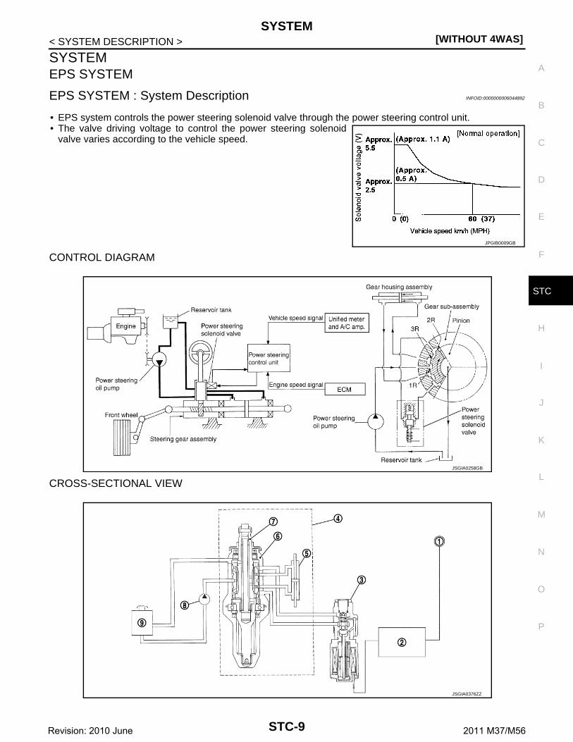
EPS SYSTEM : System Description INFOID:0000000006044892
• EPS system controls the power steering solenoid valve through the power steering control unit.• The valve driving voltage to control the power steering solenoid
valve varies according to the vehicle speed.
CONTROL DIAGRAM
CROSS-SECTIONAL VIEW
JPGIB0009GB
JSGIA0258GB
JSGIA0376ZZ
STC-9Revision: 2010 June 2011 M37/M56

[WITHOUT 4WAS]SYSTEM
< SYSTEM DESCRIPTION >
OPERATION PRINCIPLE
During Parking (When Turning The Steering Wheel To The Right.)
1. Power steering solenoid valve is closed while a vehicle is stopped.2. Pinion “1R”, “2R” and “3R” are closed depending on steering torque of steering wheel.3. Oil pressure “P” in the gear housing assembly is the sum of oil pressures occurred in “2R” and “3R”. This
results in a light steering force because of high pressure.
During High-speed Operation
1. Power steering solenoid valve is opened during high-speed operation.2. Pinion “1R”, “2R” and “3R” are closed depending on steering torque of steering wheel.3. Oil pressure “2R” does not occur because the power steering solenoid valve is on full throttle.4. Oil pressure “P” in the gear housing assembly includes only oil pressure occurred in “3R” and results in a
heavy steering force.
EPS SYSTEM : Fail-safe INFOID:0000000006046115
• EPS system enters the fail-safe mode (that allows the steeringforce to be controlled without impairing the drive ability) if any ofthe input/output values to/from EPS system (power steering con-trol unit) deviate from the standard range.
• Power steering control unit controls the driving voltage to powersteering solenoid valve for maintaining the power steering assistforce when the fail-safe function is activated. (The engine speedsignals control EPS system if any vehicle speed signal error isdetected.)
1. Combination meter 2. Power steering control unit 3. Power steering solenoid valve
4. Steering gear assembly 5. Gear housing assembly 6. Gear sub-assembly
7. Pinion 8. Power steering oil pump 9. Reservoir tank
JSGIA0020GB
JSGIA0021GB
JPGIB0010GB
STC-10Revision: 2010 June 2011 M37/M56

SYSTEM[WITHOUT 4WAS]
C
D
E
F
H
I
J
K
L
M
A
B
TC
N
O
P
< SYSTEM DESCRIPTION >
S
Error area and root cause Cancel condition
Engine speed is 1,500 rpm or more and there is no vehicle speed signal input for over 10 seconds during vehicle travel. • When a vehicle speed signal of 2 km/h (1.2
MPH) or more is inputted.• Key switch is turned OFF to ON.Vehicle speed signal has abruptly dropped from 30 km/h (19 MPH) or more to 2
km/h (1.2 MPH) or less within 1.4 seconds.
STC-11Revision: 2010 June 2011 M37/M56

[WITHOUT 4WAS]EPS CONTROL UNIT
< ECU DIAGNOSIS INFORMATION >
ECU DIAGNOSIS INFORMATIONEPS CONTROL UNIT
Reference Value INFOID:0000000006044894
TERMINAL LAYOUT
PHYSICAL VALUES
JSGIA0023ZZ
Terminal No. Description
Condition Value (Approx.)+ − Signal name
Input/Output
1(LG)
GroundPower steering solenoid valve voltage
Output
Vehicle speed: 0 km/h (0 MPH)(Engine is running)
4.4 – 6.6 V
Vehicle speed: 100 km/h (62 MPH)
1.7 – 2.9 V
3(G)
GroundIgnition switch power sup-ply
InputIgnition switch: ON Battery voltage
Ignition switch: OFF 0 V
5(B)
GroundPower steering solenoid valve ground
— Always 0 V
6(B)
Ground Ground — Always 0 V
8(GR)
Ground Vehicle speed signal Input
Vehicle speed: 40 km/h (25 MPH)CAUTION:Check air pressure of tire un-der standard condition.
SEIA0775E
STC-12Revision: 2010 June 2011 M37/M56

EPS CONTROL UNIT[WITHOUT 4WAS]
C
D
E
F
H
I
J
K
L
M
A
B
TC
N
O
P
< ECU DIAGNOSIS INFORMATION >
S
CAUTION:
When using circuit tester or oscilloscope to measure voltage for inspection, be sure not to forcibly extend any connector ter-minals.
Fail-safe INFOID:0000000006044895
• EPS system enters the fail-safe mode (that allows the steeringforce to be controlled without impairing the drive ability) if any ofthe input/output values to/from EPS system (power steering con-trol unit) deviate from the standard range.
• Power steering control unit controls the driving voltage to powersteering solenoid valve for maintaining the power steering assistforce when the fail-safe function is activated. (The engine speedsignals control EPS system if any vehicle speed signal error isdetected.)
10(V)
Ground Engine speed signal Input
Engine speed: At idle(Warm-up condition)
VQ37VHR
VK56VD
Engine speed: Approx. 2,000 rpm(Warm-up condition)
VQ37VHR
VK56VD
Terminal No. Description
Condition Value (Approx.)+ − Signal name
Input/Output
PBIA3654J
JPBIA3352ZZ
PBIA3655J
JPBIA3354ZZ
JPGIB0010GB
STC-13Revision: 2010 June 2011 M37/M56

[WITHOUT 4WAS]EPS CONTROL UNIT
< ECU DIAGNOSIS INFORMATION >
Error area and root cause Cancel condition
Engine speed is 1,500 rpm or more and there is no vehicle speed signal input for over 10 seconds during vehicle travel. • When a vehicle speed signal of 2 km/h (1.2
MPH) or more is inputted.• Key switch is turned OFF to ON.Vehicle speed signal has abruptly dropped from 30 km/h (19 MPH) or more to 2
km/h (1.2 MPH) or less within 1.4 seconds.
STC-14Revision: 2010 June 2011 M37/M56

EPS SYSTEM[WITHOUT 4WAS]
C
D
E
F
H
I
J
K
L
M
A
B
TC
N
O
P
< WIRING DIAGRAM >
S
WIRING DIAGRAMEPS SYSTEM
Wiring Diagram INFOID:0000000006044896
JCGWA0259GB
STC-15Revision: 2010 June 2011 M37/M56

[WITHOUT 4WAS]EPS SYSTEM
< WIRING DIAGRAM >
JCGWA0260GB
STC-16Revision: 2010 June 2011 M37/M56

EPS SYSTEM[WITHOUT 4WAS]
C
D
E
F
H
I
J
K
L
M
A
B
TC
N
O
P
< WIRING DIAGRAM >
S
JCGWA0261GB
STC-17Revision: 2010 June 2011 M37/M56

[WITHOUT 4WAS]EPS SYSTEM
< WIRING DIAGRAM >
JCGWA0262GB
STC-18Revision: 2010 June 2011 M37/M56

EPS SYSTEM[WITHOUT 4WAS]
C
D
E
F
H
I
J
K
L
M
A
B
TC
N
O
P
< WIRING DIAGRAM >
S
JCGWA0263GB
STC-19Revision: 2010 June 2011 M37/M56

[WITHOUT 4WAS]DIAGNOSIS AND REPAIR WORK FLOW
< BASIC INSPECTION >
BASIC INSPECTIONDIAGNOSIS AND REPAIR WORK FLOW
Work Flow INFOID:0000000006044897
DETAILED FLOW
1.COLLECT THE INFORMATION FROM THE CUSTOMER
It is also important to clarify customer complaints before inspection. First of all, reproduce symptoms, andunderstand them fully. Ask customer about his/her complaints carefully. In some cases, it is necessary tocheck symptoms by driving vehicle with customer.CAUTION:Customers are not professional. It is dangerous to make an easy guess like “maybe the customermeans that...,” or “maybe the customer mentions this symptom”.
>> GO TO 2.
2.CHECK THE STATUS
1. Power steering fluid leakage and check the power steering fluid level. Refer to ST-31, "Inspection".2. Check the drive belt tension. Refer to EM-22, "Checking" (VQ37VHR), EM-175, "Checking" (VK56VD).3. Check the power steering gear for damages, cracks and fluid leakage. Refer to ST-52, "2WD : Inspection
and Adjustment" (2WD), ST-62, "AWD : Inspection" (AWD).4. Check the relief oil pressure. Refer to ST-71, "VQ37VHR : Inspection" (VQ37VHR), ST-77, "VK56VD :
Inspection" (VK56VD).
>> GO TO 3.
3.DIAGNOSIS CHART BY SYMPTOM
Perform the diagnosis by symptom.
>> GO TO 4.
4.FINAL CHECK
Check the input/output standard values for the power steering control unit.Are the power steering control unit input/output values within standard ranges respectively?YES >> INSPECTION ENDNO >> GO TO 2.
STC-20Revision: 2010 June 2011 M37/M56

POWER SUPPLY AND GROUND CIRCUIT[WITHOUT 4WAS]
C
D
E
F
H
I
J
K
L
M
A
B
TC
N
O
P
< DTC/CIRCUIT DIAGNOSIS >
S
DTC/CIRCUIT DIAGNOSISPOWER SUPPLY AND GROUND CIRCUIT
Description INFOID:0000000006044898
Power supply to EPS system.
Diagnosis Procedure INFOID:0000000006044899
1.CHECK POWER SUPPLY (1)
1. Turn the ignition switch OFF.2. Disconnect power steering control unit harness connector.3. Check the voltage between power steering control unit harness connector and ground.
4. Turn the ignition switch ON.CAUTION:Never start the engine.
5. Check the voltage between power steering control unit harness connector and ground.
Is the inspection result normal?YES >> GO TO 3.NO >> GO TO 2.
2.CHECK POWER SUPPLY (2)
1. Turn the ignition switch OFF.2. Check 10A fuse (#46).3. Disconnect IPDM E/R harness connector.4. Check the continuity between power steering control unit harness connector and IPDM E/R harness con-
nector.
5. Check the continuity between power steering control unit harness connector and ground.
Is the inspection result normal?YES >> Perform trouble diagnosis for ignition power supply circuit. Refer to PG-84, "Wiring Diagram -
IGNITION POWER SUPPLY -".NO >> Repair or replace damaged parts.
3.CHECK GROUND CIRCUIT
1. Turn the ignition switch OFF.2. Check the continuity between power steering control unit harness connector and ground.
Power steering control unit— Voltage (Approx.)
Connector Terminal
M108 3 Ground 0 V
Power steering control unit— Voltage (Approx.)
Connector Terminal
M108 3 Ground Battery voltage
Power steering control unit IPDM E/RContinuity
Connector Terminal Connector Terminal
M108 3 E5 12 Existed
Power steering control unit— Continuity
Connector Terminal
M108 3 Ground Not existed
STC-21Revision: 2010 June 2011 M37/M56

[WITHOUT 4WAS]POWER SUPPLY AND GROUND CIRCUIT
< DTC/CIRCUIT DIAGNOSIS >
Is the inspection result normal?YES >> GO TO 4.NO >> Repair or replace damaged parts.
4.CHECK TERMINALS AND HARNESS CONNECTORS
Check the power steering control unit pin terminals for damage or loose connection with harness connector.Is the inspection result normal?YES >> INSPECTION ENDNO >> Repair or replace damaged parts.
Power steering control unit— Continuity
Connector Terminal
M108 6 Ground Existed
STC-22Revision: 2010 June 2011 M37/M56

POWER STEERING SOLENOID VALVE[WITHOUT 4WAS]
C
D
E
F
H
I
J
K
L
M
A
B
TC
N
O
P
< DTC/CIRCUIT DIAGNOSIS >
S
POWER STEERING SOLENOID VALVE
Component Function Check INFOID:0000000006044900
1.CHECK POWER STEERING SOLENOID VALVE OPERATION
Check changes in steering force from a halt condition to high-speed driving.Is the inspection result normal?YES >> INSPECTION ENDNO >> Check the power steering solenoid valve. Refer to STC-23, "Diagnosis Procedure".
Diagnosis Procedure INFOID:0000000006044901
1.CHECK POWER STEERING SOLENOID VALVE SIGNAL
Check the voltage between power steering control unit harness connector and ground.
Is the inspection result normal?YES >> GO TO 4.NO >> GO TO 2.
2.CHECK POWER STEERING SOLENOID VALVE CIRCUIT
1. Turn the ignition switch OFF.2. Disconnect power steering solenoid valve harness connector.3. Disconnect power steering control unit harness connector.4. Check the continuity between power steering solenoid valve harness connector and the power steering
control unit harness connector.
5. Check the continuity between power steering control unit harness connector and ground.
Is the inspection result normal? YES >> GO TO 3. NO >> Repair or replace error-detected parts.
3.CHECK POWER STEERING SOLENOID VALVE
Check the power steering solenoid valve. Refer to STC-24, "Component Inspection". Is the inspection result normal? YES >> GO TO 4. NO >> Power steering solenoid valve is malfunctioning. Replace gear-sub assembly. Refer to ST-45,
"2WD : Removal and Installation" (2WD), ST-55, "AWD : Removal and Installation" (AWD).
4.CHECK TERMINALS AND HARNESS CONNECTORS
Power steering control unit— Condition Voltage (Approx.)
Connector Terminal
M108 1 Ground
Vehicle speed: 0 km/h (0 MPH)(Engine is running)
4.4 – 6.6 V
Vehicle speed: 100 km/h (62 MPH) 2.4 – 3.6 V
Power steering solenoid valve Power steering control unitContinuity
Connector Terminal Connector Terminal
F55 (2WD)F45 (AWD)
1M108
1Existed
2 5
Power steering control unit— Continuity
Connector Terminal
M1081
Ground Not existed5
STC-23Revision: 2010 June 2011 M37/M56

[WITHOUT 4WAS]POWER STEERING SOLENOID VALVE
< DTC/CIRCUIT DIAGNOSIS >• Check the power steering control unit pin terminals for damage or loose connection with harness connector.• Check the power steering solenoid valve pin terminals for damage or loose connection with harness connec-
tor.Is the inspection result normal?YES >> INSPECTION ENDNO >> Repair or replace error-detected parts.
Component Inspection INFOID:0000000006044902
1.CHECK POWER STEERING SOLENOID VALVE
1. Turn the ignition switch OFF.2. Disconnect power steering solenoid valve harness connector.3. Check the resistance between power steering solenoid valve connector terminals.
4. Check the power steering solenoid valve connector by listening for its operation sound while applying bat-tery voltage to power steering solenoid valve connector terminals.
Is the inspection result normal? YES >> INSPECTION END NO >> Power steering solenoid valve is malfunctioning. Replace gear-sub assembly. Refer to ST-45,
"2WD : Removal and Installation" (2WD), ST-55, "AWD : Removal and Installation" (AWD).
Power steering solenoid valveResistance (Approx.)
Terminal
1 2 4 – 6 Ω
Power steering solenoid valveOperation sound
Terminal
1 (Positive) 2 (Negative) Existed
STC-24Revision: 2010 June 2011 M37/M56

ENGINE SPEED SIGNAL CIRCUIT[WITHOUT 4WAS]
C
D
E
F
H
I
J
K
L
M
A
B
TC
N
O
P
< DTC/CIRCUIT DIAGNOSIS >
S
ENGINE SPEED SIGNAL CIRCUIT
Diagnosis Procedure INFOID:0000000006044903
1.PERFORM ECM SELF-DIAGNOSIS
With CONSULT-IIIPerform self-diagnosis for “ENGINE”.Is any error system detected?YES >> Check the DTC. Refer to EC-102, "DTC Index" (VQ37VHR), EC-639, "DTC Index" (VK56VD).NO >> GO TO 2.
2.CHECK ENGINE SPEED SIGNAL CIRCUIT
1. Turn the ignition switch OFF.2. Disconnect ECM harness connectors.3. Disconnect power steering control unit harness connector.4. Check the continuity between ECM harness connector and power steering control unit harness connector.
*1: VQ37VHR*2: VK56VD
Is the inspection result normal?YES >> GO TO 3.NO >> Repair or replace damaged parts.
3.CHECK ENGINE SPEED SIGNAL (ECM)
1. Connect ECM harness connectors.2. Check the signal between ECM harness connector and ground with oscilloscope.
Power steering control unit ECMContinuity
Connector Terminal Connector Terminal
M108 10M107*1
M160*2110*1
169*2Existed
STC-25Revision: 2010 June 2011 M37/M56

[WITHOUT 4WAS]ENGINE SPEED SIGNAL CIRCUIT
< DTC/CIRCUIT DIAGNOSIS >
*1: VQ37VHR*2: VK56VD
Is the inspection result normal?YES >> GO TO 4.NO >> Replace ECM. Refer to EC-147, "Description" (VQ37VHR), EC-691, "Description" (VK56VD).
4.CHECK ENGINE SPEED SIGNAL (POWER STEERING CONTROL UNIT)
1. Turn the ignition switch OFF.2. Connect power steering control unit harness connector.3. Check the signal between power steering control unit harness connector and ground with oscilloscope.
ECM— Condition Value (Approx.)
Connector Terminal
M107*1
M160*2110*1
169*2Ground
Engine speed: At idle(Warm-up condition)
VQ37VHR
VK56VD
Engine speed: Approx. 2,000 rpm(Warm-up condition)
VQ37VHR
VK56VD
JMBIA0076GB
JPBIA3352ZZ
JMBIA0077GB
JPBIA3354ZZ
STC-26Revision: 2010 June 2011 M37/M56

ENGINE SPEED SIGNAL CIRCUIT[WITHOUT 4WAS]
C
D
E
F
H
I
J
K
L
M
A
B
TC
N
O
P
< DTC/CIRCUIT DIAGNOSIS >
S
Is the inspection result normal?YES >> GO TO 5.NO >> Replace power steering control unit. Refer to STC-31, "Removal and Installation".
5.CHECK TERMINALS AND HARNESS CONNECTORS
• Check the power steering control unit pin terminals for damage or loose connection with harness connector.• Check ECM pin terminals for damage or loose connection with harness connector.Is the inspection result normal?YES >> INSPECTION ENDNO >> Repair or replace damaged parts.
Power steering control unit— Condition Value (Approx.)
Connector Terminal
M108 10 Ground
Engine speed: At idle(Warm-up condition)
VQ37VHR
VQK56VD
Engine speed: Approx. 2,000 rpm(Warm-up condition)
VQ37VHR
VK56VD
JMBIA0076GB
JPBIA3352ZZ
JMBIA0077GB
JPBIA3354ZZ
STC-27Revision: 2010 June 2011 M37/M56

[WITHOUT 4WAS]VEHICLE SPEED SIGNAL CIRCUIT
< DTC/CIRCUIT DIAGNOSIS >
VEHICLE SPEED SIGNAL CIRCUIT
Diagnosis Procedure INFOID:0000000006044904
1.PERFORM COMBINATION METER SELF-DIAGNOSIS
With CONSULT-III Perform self-diagnosis for “METER/M&A”.Is any error system detected?YES >> Check the DTC. Refer to MWI-43, "DTC Index".NO >> GO TO 2.
2.CHECK VEHICLE SPEED SIGNAL CIRCUIT
1. Turn the ignition switch OFF.2. Disconnect power steering control unit harness connector.3. Disconnect combination meter harness connector.4. Check the continuity between combination meter harness connector and power steering control unit har-
ness connector.
Is the inspection result normal?YES >> GO TO 3.NO >> Repair or replace damaged parts.
3.CHECK VEHICLE SPEED SIGNAL (COMBINATION METER)
1. Connect combination meter harness connector.2. Check the combination meter input/output standard values. Refer to MWI-35, "Reference Value".Is the inspection result normal?YES >> GO TO 4.NO >> Replace combination meter. Refer to MWI-90, "Removal and Installation".
4.CHECK VEHICLE SPEED SIGNAL (POWER STEERING CONTROL UNIT)
1. Connect power steering control unit harness connector.2. Check the signal between power steering control unit harness connector and ground with oscilloscope.
Is the inspection result normal?YES >> GO TO 5.NO >> Replace power steering control unit. Refer to STC-31, "Removal and Installation".
5.CHECK TERMINALS AND HARNESS CONNECTORS
• Check the power steering control unit pin terminals for damage or loose connection with harness connector.• Check the combination meter pin terminals for damage or loose connection with harness connector.Is the inspection result normal?YES >> INSPECTION END
Power steering control unit Combination meterContinuity
Connector Terminal Connector Terminal
M108 8 M53 3 Existed
Power steering control unit— Condition Value (Approx.)
Connector Terminal
M108 8 Ground
Vehicle speed: 40 km/h (25 MPH)CAUTION:Check the air pressure of tire un-der standard condition.
JSNIA0015GB
STC-28Revision: 2010 June 2011 M37/M56

VEHICLE SPEED SIGNAL CIRCUIT[WITHOUT 4WAS]
C
D
E
F
H
I
J
K
L
M
A
B
TC
N
O
P
< DTC/CIRCUIT DIAGNOSIS >
S
NO >> Repair or replace damaged parts.
STC-29Revision: 2010 June 2011 M37/M56

[WITHOUT 4WAS]UNBALANCE STEERING WHEEL TURNING FORCE (TORQUE VARIATION)
< SYMPTOM DIAGNOSIS >
SYMPTOM DIAGNOSISUNBALANCE STEERING WHEEL TURNING FORCE (TORQUE VARIA-TION)
Description INFOID:0000000006044905
• Hard steering when fully turning the steering wheel.• Light steering when driving at a high speed.
Diagnosis Procedure INFOID:0000000006044906
1.CHECK SYSTEM FOR POWER SUPPLY AND GROUND
Perform trouble diagnosis for power supply and ground. Refer to STC-21, "Diagnosis Procedure".Is the inspection result normal?YES >> GO TO 2.NO >> Repair or replace damaged parts.
2.CHECK SYSTEM FOR VEHICLE SPEED SIGNAL
Perform trouble diagnosis for vehicle speed signal. Refer to STC-28, "Diagnosis Procedure".Is the inspection result normal?YES >> GO TO 3.NO >> Repair or replace damaged parts.
3.CHECK SYSTEM FOR ENGINE SPEED SIGNAL
Perform trouble diagnosis for engine speed signal. Refer to STC-25, "Diagnosis Procedure".Is the inspection result normal?YES >> GO TO 4.NO >> Repair or replace damaged parts.
4.CHECK SYSTEM FOR POWER STEERING SOLENOID VALVE
Perform trouble diagnosis for power steering solenoid valve. Refer to STC-23, "Diagnosis Procedure".Is the inspection result normal?YES >> Perform the symptom diagnosis for the steering system. Refer to ST-29, "NVH Troubleshooting
Chart".NO >> Repair or replace damaged parts.
STC-30Revision: 2010 June 2011 M37/M56

POWER STEERING CONTROL UNIT[WITHOUT 4WAS]
C
D
E
F
H
I
J
K
L
M
A
B
TC
N
O
P
< REMOVAL AND INSTALLATION >
S
REMOVAL AND INSTALLATIONPOWER STEERING CONTROL UNIT
Removal and Installation INFOID:0000000006044907
REMOVAL1. Remove instrument lower panel RH. Refer to IP-12, "Exploded View".2. Disconnect power steering control unit connector.3. Remove power steering control unit.
INSTALLATIONInstall in the reverse order of removal.
STC-31Revision: 2010 June 2011 M37/M56
[WITH 4WAS]PRECAUTIONS
< PRECAUTION >
PRECAUTIONPRECAUTIONS
Precaution for Supplemental Restraint System (SRS) "AIR BAG" and "SEAT BELT PRE-TENSIONER" INFOID:0000000006046076
The Supplemental Restraint System such as “AIR BAG” and “SEAT BELT PRE-TENSIONER”, used alongwith a front seat belt, helps to reduce the risk or severity of injury to the driver and front passenger for certaintypes of collision. This system includes seat belt switch inputs and dual stage front air bag modules. The SRSsystem uses the seat belt switches to determine the front air bag deployment, and may only deploy one frontair bag, depending on the severity of a collision and whether the front occupants are belted or unbelted.Information necessary to service the system safely is included in the “SRS AIR BAG” and “SEAT BELT” of thisService Manual.WARNING:• To avoid rendering the SRS inoperative, which could increase the risk of personal injury or death in
the event of a collision that would result in air bag inflation, all maintenance must be performed byan authorized NISSAN/INFINITI dealer.
• Improper maintenance, including incorrect removal and installation of the SRS, can lead to personalinjury caused by unintentional activation of the system. For removal of Spiral Cable and Air BagModule, see the “SRS AIR BAG”.
• Do not use electrical test equipment on any circuit related to the SRS unless instructed to in thisService Manual. SRS wiring harnesses can be identified by yellow and/or orange harnesses or har-ness connectors.
PRECAUTIONS WHEN USING POWER TOOLS (AIR OR ELECTRIC) AND HAMMERSWARNING:• When working near the Air Bag Diagnosis Sensor Unit or other Air Bag System sensors with the
ignition ON or engine running, DO NOT use air or electric power tools or strike near the sensor(s)with a hammer. Heavy vibration could activate the sensor(s) and deploy the air bag(s), possiblycausing serious injury.
• When using air or electric power tools or hammers, always switch the ignition OFF, disconnect thebattery, and wait at least 3 minutes before performing any service.
Precaution Necessary for Steering Wheel Rotation after Battery DisconnectINFOID:0000000006046077
NOTE:• Before removing and installing any control units, first turn the push-button ignition switch to the LOCK posi-
tion, then disconnect both battery cables.• After finishing work, confirm that all control unit connectors are connected properly, then re-connect both
battery cables.• Always use CONSULT-III to perform self-diagnosis as a part of each function inspection after finishing work.
If a DTC is detected, perform trouble diagnosis according to self-diagnosis results.For vehicle with steering lock unit, if the battery is disconnected or discharged, the steering wheel will lock andcannot be turned.If turning the steering wheel is required with the battery disconnected or discharged, follow the operation pro-cedure below before starting the repair operation.
OPERATION PROCEDURE1. Connect both battery cables.
NOTE:Supply power using jumper cables if battery is discharged.
2. Turn the push-button ignition switch to ACC position.(At this time, the steering lock will be released.)
3. Disconnect both battery cables. The steering lock will remain released with both battery cables discon-nected and the steering wheel can be turned.
4. Perform the necessary repair operation.
STC-32Revision: 2010 June 2011 M37/M56

PRECAUTIONS[WITH 4WAS]
C
D
E
F
H
I
J
K
L
M
A
B
TC
N
O
P
< PRECAUTION >
S
5. When the repair work is completed, re-connect both battery cables. With the brake pedal released, turnthe push-button ignition switch from ACC position to ON position, then to LOCK position. (The steeringwheel will lock when the push-button ignition switch is turned to LOCK position.)
6. Perform self-diagnosis check of all control units using CONSULT-III.
Precautions for Removal and Installation of 4WAS Components INFOID:0000000006115305
• Set the vehicle to the straight-ahead position when checking 4WAS and removing each component.• Remove the battery terminal 10 minutes after turning the ignition switch OFF from ON and perform the
removal of each component when removing the 4WAS front control unit.• Perform the neutral position adjustment for the steering angle sensor after the replacement of steering angle
sensor. Refer to BRC-68, "Work Procedure".• Refer to STC-85, "Description" for the replacement of 4WAS front control unit.• Refer to STC-87, "Description" for the replacement of 4WAS front actuator.• Refer to STC-86, "Description" for the replacement of 4WAS main control unit.
Precautions for Harness Repair INFOID:0000000006115306
4WAS COMMUNICATION LINE• Solder the repaired area and wrap tape around the soldered area.
NOTE:A fray of twisted lines must be within 110 mm (4.33 in).
• Bypass connection is never allowed at the repaired area.NOTE:Bypass connection may cause 4WAS communication error asspliced wires that are separate from the main line or twisted lineslose noise immunity.
• Replace the applicable harness as an assembly if error is detectedon the shield lines of 4WAS communication line.
SKIB8766E
SKIB8767E
STC-33Revision: 2010 June 2011 M37/M56

[WITH 4WAS]COMPONENT PARTS
< SYSTEM DESCRIPTION >
SYSTEM DESCRIPTIONCOMPONENT PARTSEPS SYSTEM
EPS SYSTEM : Component Parts Location INFOID:0000000006044915
EPS SYSTEM : Component Description INFOID:0000000006044916
EPS SYSTEM : 4WAS Main Control Unit INFOID:0000000006044917
• The power steering solenoid valve activation voltage is controlled by each sensor signal.• The power steering solenoid valve activation voltage is controlled by 4WAS main control unit for maintaining
the power steering force in the fail-safe mode. (EPS system is controlled by the engine speed signal if thevehicle speed signal error is detected.)
EPS SYSTEM : Power Steering Solenoid Valve INFOID:0000000006044918
The power steering oil pressure in the gear housing assembly is controlled.4WAS SYSTEM
1. Power steering solenoid valve 2. 4WAS rear motor relay 3. 4WAS main control unit
A. Steering gear assembly B. Inside the trunk side finisher (left)
:Vehicle front
JPGIB0011ZZ
Component parts Reference/Function
4WAS main control unit STC-34, "EPS SYSTEM : 4WAS Main Control Unit"
Power steering solenoid valve STC-34, "EPS SYSTEM : Power Steering Solenoid Valve"
ABS actuator and electric unit (control unit)
BRC-15, "System Description"
ECMEC-44, "ENGINE CONTROL SYSTEM : System Description" (VQ37VHR)EC-569, "ENGINE CONTROL SYSTEM : System Description" (VK56VD)
STC-34Revision: 2010 June 2011 M37/M56

COMPONENT PARTS[WITH 4WAS]
C
D
E
F
H
I
J
K
L
M
A
B
TC
N
O
P
< SYSTEM DESCRIPTION >
S
4WAS SYSTEM : Component Parts Location INFOID:0000000006044919
1. 4WAS front control unit 2. 4WAS front actuator 3. 4WAS rear motor
4. 4WAS rear actuator 5. Rear wheel steering angle sensor 6. 4WAS main control unit
7. 4WAS rear motor relay 8. Drive mode select switchRefer to DMS-3, "Component Parts Location".
9. A/C auto AMP.Refer to HAC-7, "AUTOMATIC AIR CONDITIONING SYSTEM (WITH FOREST AIR) : Component Parts Location" [automatic air conditioning system (with forest air)], HAC-10, "AUTOMATIC AIR CONDITIONING SYSTEM (WITHOUT FOREST AIR) : Component Parts Location" [auto-matic air conditioning system (with-out forest air)], HAC-14, "FOREST AIR SYSTEM : Component Parts Lo-cation" (forest air system).
JPGIB0012ZZ
STC-35Revision: 2010 June 2011 M37/M56

[WITH 4WAS]COMPONENT PARTS
< SYSTEM DESCRIPTION >
4WAS SYSTEM : Component Description INFOID:0000000006044920
4WAS SYSTEM : 4WAS Front Control Unit INFOID:0000000006044921
• Each sensor signal controls 4WAS front actuator.• The fail-safe functions stops the rear wheel angle function (the front wheel is the steering wheel cutting
angle) when the electric components and the mechanical components are malfunctioning.• The protection function mode stops 4WAS system intermittently when 4WAS system continues high loaded
condition and overheat condition or the input signal does not transmit to 4WAS front control unit.• 4WAS front control unit and 4WAS main control unit control the 4WAS system by 4WAS communication line
to optimize control.
10. ECMRefer to EC-24, "ENGINE CON-TROL SYSTEM : Component Parts Location" (VQ37VHR), EC-548, "ENGINE CONTROL SYSTEM : Component Parts Location" (VK56VD).
11. Stop lamp switchRefer to BRC-13, "Stop Lamp Switch".
12. ABS actuator and electric unit (con-trol unit)Refer to BRC-10, "Component Parts Location".
13. Steering angle sensorRefer to BRC-13, "Steering Angle Sensor".
A. Inside globe box assembly B. Inside the instrument driver lower panel
C. 4WAS warning lamp (Inside combi-nation meter)
D. Rear suspension E. Inside the trunk side finisher (left)
Component parts Reference/Function
4WAS front control unit STC-36, "4WAS SYSTEM : 4WAS Front Control Unit"
4WAS front actuator
4WAS front motor
STC-37, "4WAS SYSTEM : 4WAS Front Actuator"4WAS front lock solenoid valve
Front wheel steering angle sensor
4WAS main control unit STC-37, "4WAS SYSTEM : 4WAS Main Control Unit"
4WAS rear actuator4WAS rear motor
STC-37, "4WAS SYSTEM : 4WAS Rear Actuator"Rear wheel steering angle sensor
Power steering solenoid valveSTC-34, "EPS SYSTEM : Power Steering Solenoid Valve"
Stop lamp switch The stop lamp switch condition is detected.
4WAS warning lamp STC-42, "4WAS SYSTEM : System Description"
ECM
EC-44, "ENGINE CONTROL SYSTEM : System De-scription" (VQ37VHR)EC-569, "ENGINE CONTROL SYSTEM : System De-scription" (VK56VD)
ABS actuator and electronic unit (control unit) BRC-15, "System Description"
A/C auto AMP.
HAC-19, "AUTOMATIC AIR CONDITIONING SYS-TEM (WITH FOREST AIR) : System Description" [Au-tomatic air conditioning system (with forest air)]HAC-27, "AUTOMATIC AIR CONDITIONING SYS-TEM (WITHOUT FOREST AIR) : System Description" [Automatic air conditioning system (without forest air)]HAC-35, "FOREST AIR SYSTEM : System Descrip-tion" (Forest air system)
Drive mode select switch DMS-4, "Drive Mode Select Switch"
Steering angle sensor BRC-13, "Steering Angle Sensor"
STC-36Revision: 2010 June 2011 M37/M56

COMPONENT PARTS[WITH 4WAS]
C
D
E
F
H
I
J
K
L
M
A
B
TC
N
O
P
< SYSTEM DESCRIPTION >
S
4WAS SYSTEM : 4WAS Main Control Unit INFOID:0000000006044922
• 4WAS rear actuator and the power steering solenoid valve is controlled by each sensor signal.• The fail-safe functions stops the rear wheel angle function (the front wheel is the steering wheel cutting
angle) when the electric components and the mechanical components are malfunctioning.• The power steering solenoid valve activation voltage is controlled by 4WAS main control unit for maintaining
the power steering force in the fail-safe mode. (EPS system is controlled by the engine speed signal if thevehicle speed signal error is detected.)
• The protective function stops 4WAS system temporarily when the input signal is not inputted to 4WAS maincontrol unit (When battery-power dose not work temporarily).
• 4WAS front control unit and 4WAS main control unit perform two-way transmitting/receiving signals for opti-mal control of 4WAS system via 4WAS communication line.
4WAS SYSTEM : 4WAS Front Actuator INFOID:0000000006044923
• 4WAS front actuator mainly consists of five components. [4WAS front lock solenoid valve (lock structure),front wheel steering angle sensor, 4WAS front motor, gear shaft, and spiral cable]
- 4WAS front motor, 4WAS front lock solenoid valve, front wheel steering angle sensor and gear shaft is inte-grated with 4WAS front actuator.
- 4WAS front lock solenoid valve (lock structure) is controlled by the 4WAS front control unit, and locks/unlocks 4WAS front actuator.
- If a strong force (rotation direction) is applied to 4WAS front actuator, the locking mechanism (holder)absorbs the force and locks 4WAS front actuator.
- Gear shaft is an output axis of 4WAS front motor. (Gear shaft = 4WAS front motor revolution + steeringangle)
- Spiral cables mean the power line and signal lines of 4WAS front motor.• 4WAS front actuator rotates together with steering wheel.• 4WAS front actuator is activated by 4WAS front motor.• Front wheel steering angle sensor detects a turning angle of 4WAS front motor.• Wiring connected to 4WAS front actuator is integrated with 4WAS front actuator.
4WAS FRONT MOTOR4WAS front motor controls number of revolutions by a command value from the 4WAS front control unit.
4WAS FRONT LOCK SOLENOID VALVE• 4WAS front actuator releases the lock when the engine speed signal is “ON”. 4WAS front actuator applies
the lock when the engine speed signal is “OFF”.• Secure the inside of 4WAS front actuator temporarily. (It operates when performing active test with fail-safe
function and CONSULT-III.)• CAUTION:
Never perform other than trouble diagnosis, etc.• The front steering gear ratio (4WAS front actuator) changes with 4WAS front motor and the gear shaft when
releasing the lock structure (4WAS front lock solenoid valve).NOTE:The lock structure is released when turning 4WAS lock solenoid valve ON.
• The lock structure (holder) absorbs force and applies the lock when applying strong force to 4WAS frontactuator.CAUTION:Replace 4WAS front actuator when the system breaks down due to the excessive external force(rotating direction) applied to 4WAS front actuator.
FRONT WHEEL STEERING ANGLE SENSORThe front wheel steering angle increased/decreased degree is detected.
4WAS SYSTEM : 4WAS Rear Actuator INFOID:0000000006044924
• 4WAS rear actuator mainly consists of three components. (4WAS rear motor, motor shaft / HRH gear andrear wheel steering angle sensor)
• 4WAS rear actuator is activated by 4WAS rear motor.• The irreversible efficiency performance hypoid gear (motor shaft / HRH gear) secure the toe-stiffness of rear
wheels against the road external force and keep the steering angle when system is malfunction.• The power from the pinion gear (motor side) is transmitted, but the pinion gear does not rotate as caused by
the gear mechanical characteristics (teeth angle) even though the ring gear (tire side) starts to rotate.
STC-37Revision: 2010 June 2011 M37/M56

[WITH 4WAS]COMPONENT PARTS
< SYSTEM DESCRIPTION >• The rear wheel steering angle increased/decreased degree is detected.
4WAS REAR MOTOR4WAS rear motor controls number of revolutions by a command value from the 4WAS main control unit.
REAR WHEEL ANGLE SENSORThe rear wheel steering angle increased/decreased degree is detected.
STC-38Revision: 2010 June 2011 M37/M56

SYSTEM[WITH 4WAS]
C
D
E
F
H
I
J
K
L
M
A
B
TC
N
O
P
< SYSTEM DESCRIPTION >
S
SYSTEMEPS SYSTEM
EPS SYSTEM : System Description INFOID:0000000006044925
DESCRIPTION• The EPS system controls the power steering solenoid valve with 4WAS main control unit.• The power steering solenoid valve control changes the power
steering solenoid valve activation voltage according to the vehiclespeed.
SYSTEM DIAGRAM
Sectional View
JPGIB0009GB
JSGIA0258GB
SGIA1389E
STC-39Revision: 2010 June 2011 M37/M56

[WITH 4WAS]SYSTEM
< SYSTEM DESCRIPTION >
OPERATION PRINCIPLEWhen turning the steering wheel to the right.
During Parking
1. Power steering solenoid valve is closed while a vehicle is stopped.2. Pinion “1R”, “2R” and “3R” are closed depending on steering torque of steering wheel.3. Oil pressure “P” in the gear housing assembly is the sum of oil pressures occurring in “2R” and “3R”. This
results in a light steering force because of high pressure.
During High-speed Operation
1. Power steering solenoid valve is opened during high-speed operation.2. Pinion “1R”, “2R” and “3R” are closed depending on steering torque of steering wheel.3. “2R” is bypassed to the return port by the EPS solenoid valve.4. Oil pressure “P” in the gear housing assembly includes only oil pressure occurring in “3R” and results in a
heavy steering force.
EPS SYSTEM : Fail-safe (4WAS Main Control Unit) INFOID:0000000006046119
• EPS system (4WAS main control unit) enters the fail-safe mode(that allows the steering force to be controlled without impairing thedrive ability) if the input from each sensor is not within the specifiedrange. Then, 4WAS warning lamp turns ON.
1. Vehicle speed sensor 2. 4WAS main control unit 3. Power steering solenoid valve
4. Steering gear assembly 5. Gear housing assembly 6. Gear-sub assembly
7. Pinion 8. Power steering oil pump 9. Reservoir tank
JSGIA0012GB
JSGIA0013GB
JPGIB0014GB
STC-40Revision: 2010 June 2011 M37/M56
SYSTEM[WITH 4WAS]
C
D
E
F
H
I
J
K
L
M
A
B
TC
N
O
P
< SYSTEM DESCRIPTION >
S
4WAS SYSTEM
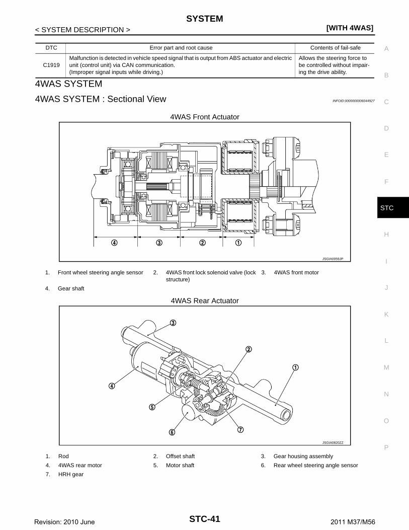
4WAS SYSTEM : Sectional View INFOID:0000000006044927
4WAS Front Actuator
4WAS Rear Actuator
DTC Error part and root cause Contents of fail-safe
C1919Malfunction is detected in vehicle speed signal that is output from ABS actuator and electric unit (control unit) via CAN communication.(Improper signal inputs while driving.)
Allows the steering force to be controlled without impair-ing the drive ability.
JSGIA0059JP
1. Front wheel steering angle sensor 2. 4WAS front lock solenoid valve (lock structure)
3. 4WAS front motor
4. Gear shaft
JSGIA0820ZZ
1. Rod 2. Offset shaft 3. Gear housing assembly
4. 4WAS rear motor 5. Motor shaft 6. Rear wheel steering angle sensor
7. HRH gear
STC-41Revision: 2010 June 2011 M37/M56

[WITH 4WAS]SYSTEM
< SYSTEM DESCRIPTION >
4WAS SYSTEM : System Description INFOID:0000000006044928
• 4WAS system consists of two control units (4WAS front control unit and 4WAS main control unit), 4WASfront actuator and 4WAS rear actuator components.
• 4WAS main control unit calculates front wheel and rear wheel angles via CAN communication based on theinformation of the steering angle sensor signal and vehicle speed signal.
• 4WAS main control unit controls 4WAS rear actuator according to the value calculated in 4WAS main controlunit.
• It transmits the value that is calculated by 4WAS main control unit to 4WAS front control unit via 4WAS com-munication line (exclusive line of 4WAS system). 4WAS front control unit controls 4WAS front actuatorbased on the received demand.
• Self-diagnosis can be performed with CONSULT-III at each control unit to another (4WAS front control unitand 4WAS main control unit).
• INFINITY drive mode selector make it possible to change the steering characteristics of the front and rearwheels, and drive mode select switch is able to select STANDARD mode or SPORT mode.
SYSTEM DIAGRAM
INPUT/OUTPUT SIGNALIt transmits/receives each signal from the following control unit via communication line.
*: Communication line between 4WAS front control unit and 4WAS main control unit
Operation DescriptionThe following performance is gained by controlling the best front wheel steering angle and the rear wheelsteering angle.• The desirable vehicle movement is gained toward the driver's steering angle operation (steering angle).
JPGIB0013GB
Component parts Control signal
4WAS main control unit Transmits/receives the following signal to 4WAS main control unit via communication line*.• 4WAS system control signal
Steering angle sensorTransmits the following signal to 4WAS main control unit via CAN communication line.• Steering angle sensor signal
ABS actuator and electronic unit (control unit)
Transmits the following signal to 4WAS main control unit via CAN communication line.• Vehicle speed signal
ECMTransmits the following signal to 4WAS main control unit via CAN communication line.• Engine speed signal
Combination meterReceives the following signal to 4WAS main control unit via CAN communication line.• 4WAS warning lamp signal
A/C auto amp.Transmits the following signal to 4WAS main control unit via CAN communication line.• Drive mode select switch signal
STC-42Revision: 2010 June 2011 M37/M56

SYSTEM[WITH 4WAS]
C
D
E
F
H
I
J
K
L
M
A
B
TC
N
O
P
< SYSTEM DESCRIPTION >
S
• The steering gear ratio changes according to the vehicle speed.The steering wheel operation (steering angle) load decreases.
• In SPORT mode, the steering characteristics of the front and rearwheels are switched to reduce load of steering wheel operation(steering angle) more than that in STANDARD mode and enablesmooth motion.NOTE:• When driving at low speed: In SPORT mode, make front steering
wheel operation (steering angle) increase more than that inSTANDARD mode.
• When driving at high speed: In SPORT mode, make rear steer-ing wheel operation (steering angle) decrease more than that inSTANDARD mode.
When Driving at Low SpeedIncreased front wheel angle gains the optimum front wheel angle byminimum steering wheel operation (steering angle).
When Driving at Middle SpeedIncrease the front steering angle while controlling to turn the rearwheel steering angle to the same steering angle side of steeringwheel operation (steering angle). these operations make responsebetter for vehicle yaw rate/lateral acceleration and also decrease theangle of sideslip.
When Driving at High SpeedDecrease the front wheel steering angle while controlling to turn therear wheel steering angle to the same steering angle side of steeringwheel operation (steering angle). these operations make carresponse better and vehicle stability higher.
4WAS WARNING LAMP INDICATION CONDITION• 4WAS system stops (error) when turning 4WAS warning lamp ON.• Turn 4WAS warning lamp ON when ignition switch turns ON from OFF for the purpose of lamp check. Then,
turn 4WAS warning lamp OFF after the engine is started if system is normal.
JSGIA0080GB
JSGIA0050GB
JSGIA0082GB
JSGIA0084GB
Condition 4WAS warning lamp
Ignition switch OFF OFF
Ignition switch ON ON
STC-43Revision: 2010 June 2011 M37/M56

[WITH 4WAS]SYSTEM
< SYSTEM DESCRIPTION >
4WAS SYSTEM : Fail-safe (4WAS Front Control Unit) INFOID:0000000006046116
4WAS system enters in the fail-safe mode (4WAS system is stopped), and 4WAS warning lamp turns ON(except DTC “C1633”) if an error is detected in 4WAS system component part.
*: Communication line between 4WAS front control unit and 4WAS main control unit
4WAS SYSTEM : Fail-safe (4WAS Main Control Unit) INFOID:0000000006046120
4WAS system enters in the fail-safe mode (4WAS system stopped) and 4WAS warning lamp turns ON if anerror is detected in 4WAS system (4WAS main control unit) component part.
After engine starts (system normal) OFF
4WAS system malfunction ON
Condition 4WAS warning lamp
DTC Error area and root cause Contents of fail-safe
C16214WAS front motor current valve error is detected.(4WAS front motor current valve is excessively large.)
4WAS system is stopped.
C16224WAS front motor voltage valve or current error valve is detected.(4WAS front motor voltage valve error is detected.)(Voltage valve or current valve error is detected when starting the system.)
C1627The indication value from 4WAS front actuator (front wheel angle) differs from the value from 4WAS front control unit.
C1628 The front wheel steering angle sensor error is detected.
C1631 An error is detected inside 4WAS front control unit.
C1632 An error is detected inside 4WAS front control unit.
C1633 An error is detected inside 4WAS front control unit.
C1651 The ignition voltage signal error is detected.
C1652 4WAS front motor main power supply error is detected.
C1654 An error is detected on the main relay power supply inside 4WAS front control unit.
C16554WAS front motor 3-phase current error is detected.(Current is not applied to 4WAS front motor)
C16614WAS front lock solenoid valve error is detected.(An electric activation error is detected.)
C16674WAS front lock solenoid valve (lock) error is detected.(An error is detected in lock condition.)
C16684WAS front lock solenoid valve (lock) error is detected.(Excessive force is applied to the lock.)
C16694WAS front actuator error is detected.(An error is detected in unlock condition.)
C1671 4WAS front actuator adjustment is not performed.
C1672 4WAS front actuator adjustment is incomplete.
C16844WAS communication line* data communication error is detected.(An error signal is detected from 4WAS main control unit.)
C16854WAS communication line* data communication error is detected.(An error signal is detected from 4WAS main control unit.)
C1686An error is detected on 4WAS main control unit side.(4WAS main control unit fail-safe mode)
U1000When 4WAS front control unit is not transmitting or receiving 4WAS communication signal for 2 seconds or more.
U1002When 4WAS front control unit is not transmitting or receiving 4WAS communication signal for 2 seconds or less.
U1010When detecting error during the initial diagnosis of 4WAS controller of 4WAS front control unit
STC-44Revision: 2010 June 2011 M37/M56

SYSTEM[WITH 4WAS]
C
D
E
F
H
I
J
K
L
M
A
B
TC
N
O
P
< SYSTEM DESCRIPTION >
S
DTC Error area and root cause Contents of fail-safe
C1900 An error is detected inside 4WAS main control unit.
4WAS system stopped.
C1901 An error is detected inside 4WAS main control unit.
C19024WAS rear motor current error is detected.(4WAS rear motor current output direction differs.)
C19034WAS rear motor current error is detected.(Current is input to 4WAS main control unit if 4WAS main control unit output is “OFF”.)
C19044WAS rear motor current error is detected.(4WAS rear motor output is overcurrent.)
C1905 An error is detected inside 4WAS main control unit.
C1906 An error is detected inside 4WAS main control unit.
C1907 An error is detected inside 4WAS main control unit.
C1908 An error is detected inside 4WAS main control unit.
C1909 An error is detected inside 4WAS main control unit.
C19104WAS rear motor inside error is detected.(4WAS rear motor does not move or the rear wheel angle sensor does not change if 4WAS main control unit output is 14 A or more.)
C19114WAS rear motor voltage error is detected.(4WAS rear motor voltage is low.)
C19124WAS rear motor voltage error is detected.(Voltage is applied to 4WAS main motor when 4WAS main control unit output is “OFF”.)
C19134WAS rear motor current error is detected.(4WAS rear motor does not move or the rear wheel angle sensor output does not change when 4WAS main control unit output is 18 A or more, and 4WAS main motor output is low.)
C1914 The rear wheel angle sensor power supply error is detected.
C1915 The rear wheel angle sensor signal (main) error is detected.
C1916 If the rear wheel angle sensor signal (sub) error is detected.
C1917The rear wheel angle sensor signal (main and sub) error is detected.(The output signal value differs temporarily between main and sub.)
C1918The rear wheel angle sensor signal (main and sub) error is detected.(The output signal value differs between main and sub.)
C1919Malfunction is detected in vehicle speed signal that is output from ABS actuator and elec-tric unit (control unit) via CAN communication.(Improper signal inputs while driving.)
C1920Malfunction is detected in steering angle sensor signal that is output from steering angle sensor via CAN communication.(No transmission from the steering angle sensor)
C1921Malfunction is detected in engine speed signal that is output from ECM via CAN communication.(Improper signal is input engine speed.)
When DTC “C1921” is detect-ed before starting the engine.
When DTC “C1921” is detect-ed after starting the engine.
—
STC-45Revision: 2010 June 2011 M37/M56

[WITH 4WAS]SYSTEM
< SYSTEM DESCRIPTION >
*: Communication line between 4WAS front control unit and 4WAS main control unit
4WAS SYSTEM : Protection Function (4WAS Front Control Unit) INFOID:0000000006046117
4WAS system enters in the protection function mode (4WAS system is temporarily stopped) if 4WAS systemcontinues the heavy load condition and the overheat condition.4WAS system reactivates automatically if theheavy load condition and the overheat condition are resolved.4WAS warning lamp continues turning OFF inthe protection function mode.
4WAS SYSTEM : Protection Function (4WAS Main Control Unit) INFOID:0000000006046118
4WAS system enters in the protection function mode (4WAS system temporarily stopped) if 4WAS systemcontinues the heavy load condition or the sensor self-check condition. (4WAS system reactivates automati-
C1922 An error is detected inside 4WAS main control unit.
4WAS system stopped.
C1923Malfunction is detected in steering angle sensor signal that is output from steering angle sensor via CAN communication.[Steering angle sensor input signal error is detected when driving.]
C1924Driving continuously at 10 km (6 mile) or more while the steering angle sensor value is not L10° - R10°.(Not detected in 4WAS front control unit fail-safe mode)
C1925 An error is detected inside 4WAS main control unit.
C1926
Malfunction is detected in steering angle sensor signal that is output from steering angle sensor via CAN communication.(When improper signal inputs to steering angle sensor and steering angle sensor itself de-tects the malfunction)
C1927 An error is detected inside 4WAS main control unit.
C1928 An error is detected inside 4WAS main control unit.
C1930An error is detected on 4WAS front control unit side.(4WAS front control unit fail-safe mode)
C19314WAS communication line* data communication error is detected.(An error signal is detected from 4WAS front control unit.)
C1932If the steering angle sensor error is detected.(Steering angle sensor output value is abnormal.)
C1933 An error is detected inside 4WAS main control unit.
U1000When 4WAS main control unit is not transmitting or re-ceiving CAN communication signal for 2 seconds or more.
When 4WAS main control unit is not receiving following CAN communication signal.• Drive mode select switch
signal
Mode is fixed to the mode when a malfunction of drive mode selector occurs. The mode is fixed to STANDARD mode after ignition switch OFF→ ON.
When 4WAS main control unit is not receiving following CAN communication signal or 4WAS communication signal.• Steering angle sensor• Vehicle speed signal• Engine speed signal• 4WAS system control signal
4WAS system stopped.
U1010When detecting error during the initial diagnosis of CAN controller of 4WAS main control unit.
DTC Error area and root cause Contents of fail-safe
DTC Error area and root cause Contents of protection function
— 4WAS front control unit power supply temporary malfunctioning condition
4WAS system is temporarily stopped.— 4WAS front control unit overheat condition
— 4WAS front actuator overheat condition
— 4WAS front control unit heavy load condition
STC-46Revision: 2010 June 2011 M37/M56

SYSTEM[WITH 4WAS]
C
D
E
F
H
I
J
K
L
M
A
B
TC
N
O
P
< SYSTEM DESCRIPTION >
S
cally if the heavy load condition and the self-check condition are resolved.) 4WAS warning lamp stays OFF inthe protection function mode.
DTC Error area and root cause Contents of protection function
— 4WAS main control unit power supply temporary malfunctioning condition
4WAS system is temporarily stopped.— 4WAS system heavy load condition
— The sensor of 4WAS system is in self-check condition
STC-47Revision: 2010 June 2011 M37/M56

[WITH 4WAS]DIAGNOSIS SYSTEM (4WAS FRONT CONTROL UNIT)
< SYSTEM DESCRIPTION >
DIAGNOSIS SYSTEM (4WAS FRONT CONTROL UNIT)
CONSULT-III Function [4WAS(FRONT)] INFOID:0000000006044933
APPLICATION ITEMSCONSULT-III can display each diagnostic item using the diagnostic test modes as follows.
*1 : The following diagnosis information is erased by erasing.• DTC• Freeze frame data (FFD)*2 : Communication line between 4WAS front control unit and 4WAS main control unit
ECU IDENTIFICATION4WAS front control unit part number can be read.
SELF DIAGNOSTIC RESULTRefer to STC-61, "DTC Index".
When “0” is displayed• It indicates that the system is presently malfunctioning.
When “1 – 39” is displayed• It indicates that system malfunction in the past is detected, but the system is presently normal.
NOTE:Each time when ignition switch is turned OFF to ON, numerical number increases in 1→2→3...38→39.When the operation number of times exceeds 39, the number do not increase and “39” is displayed untilself-diagnosis is erased.
FREEZE FRAME DATA (FFD)The following vehicle status is recorded when DTC is detected and is displayed on CONSULT-III.
Diagnostic test mode Function
ECU Identification 4WAS front control unit part number can be read.
Self Diagnostic Result Self-diagnostic results and freeze frame data can be read and erased quickly.*1
Data Monitor Input/Output data in the 4WAS front control unit can be read.
CAN diagnostic support monitor The results of transmit/receive diagnosis of 4WAS communication*2 can be read.
Active TestDiagnostic Test Mode in which CONSULT-III drives some actuators apart from the 4WAS front con-trol unit and also shifts some parameters in a specified range.
Freeze Frame Data Item Description
4WAS STR ANGThe steering angle sensor signal received from 4WAS main control unit via 4WAS commu-nication line * is indicated when DTC is detected.
VEHICLE SPEEDThe vehicle speed signal received from 4WAS main control unit via 4WAS communication line * is indicated when DTC is detected.
MOTOR CURRENT4WAS front motor power supply current is indicated when DTC is detected when DTC is de-tected.(4WAS front control unit main power supply)
MTR CRNT ESTMThe value, which 4WAS front control unit presumes 4WAS front motor power supply current, is indicated when DTC is detected.(4WAS front control unit main power supply)
ACTR ROTA ANG 4WAS front actuator increased/decreased angle is indicated when DTC is detected.
LG VOLT 4WAS front lock solenoid valve voltage is indicated when DTC is detected.
THERM TEMP 4WAS front control unit internal temperature is indicated when DTC is detected.
MOTOR VOLT4WAS front motor power supply voltage is indicated when DTC is detected.(4WAS front control unit main power supply)
IGN VOLT4WAS front control unit power supply voltage is indicated when DTC is detected.(Ignition switch power supply voltage)
STC-48Revision: 2010 June 2011 M37/M56

DIAGNOSIS SYSTEM (4WAS FRONT CONTROL UNIT)[WITH 4WAS]
C
D
E
F
H
I
J
K
L
M
A
B
TC
N
O
P
< SYSTEM DESCRIPTION >
S
ACTR ANG COMMThe command value of 4WAS front actuator increased/decreased angle received from 4WAS main control unit via 4WAS communication line* is indicated when DTC is detected.
ACTR ROTA SPD 4WAS front actuator increased/decreased rotation speed is indicated when DTC is detected.
DUTY COMMAND 4WAS front actuator command voltage ratio is indicated when DTC is detected.
LOCK DTY COMM 4WAS front lock solenoid valve command voltage ratio is indicated when DTC is detected.
MTR U VOLT 4WAS front motor U terminal voltage is indicated when DTC is detected.
MTR V VOLT 4WAS front motor V terminal voltage is indicated when DTC is detected.
MTR W VOLT 4WAS front motor W terminal voltage is indicated when DTC is detected.
ACT TEMP ESTMThe value, which 4WAS front control unit presumes 4WAS front actuator temperature, is in-dicated when DTC is detected.
MTR PHZ CRNT 4WAS front motor U, V, and W terminal current is indicated when DTC is detected.
ACTR DEVI ANG4WAS front actuator command value and the activation angle difference are indicated when DTC is detected.
ACTR ANGL SUBThe final command value, which 4WAS front control unit calculates 4WAS front actuator command value transmitted from 4WAS front control unit through 4WAS communication line*, is indicated when DTC is detected.
STR ANGL SPDIt displays an engine speed value obtained from an angle calculated with the 4WAS front control unit, based on steering angle sensor speed signals transmitted from the 4WAS main control unit through the 4WAS communication line* when DTC is detected.
OVRLD JDG FLG 4WAS system (the entire system) heavy load condition is indicated when DTC is detected.
OVRLD JDG TMGIt displays record of 4WAS system (entire 4WAS system) high load when DTC is detected.(It displays time of occurrence before turning ignition switch ON.)
ACT PRTCT FLG4WAS system (4WAS front actuator) over-heated condition is indicated when DTC is detect-ed.
ACT PRTCT TMGIt displays record of 4WAS system (4WAS front actuator) overheating when DTC is detected.(It displays time of occurrence before turning ignition switch ON.)
ECU PRTCT FLG4WAS system (4WAS front control unit) over-heated condition is indicated when DTC is de-tected.
ECU PRTCT TMGIt displays record of 4WAS system (4WAS front control unit) overheating when DTC is de-tected.(It displays time of occurrence before turning ignition switch ON.)
DRV TMPO FLG4WAS system (4WAS front motor terminal power supply converter) intermittent error is indi-cated when DTC is detected.
DRV TMPO TMGIt displays record of 4WAS system (terminal power supply converter of 4WAS front motor) intermittent abnormal when DTC is detected.(It displays time of occurrence before turning ignition switch ON.)
MTR PW TMP FL4WAS system (4WAS front motor terminal power supply front driver) intermittent error is in-dicated when DTC is detected.
MTR PW TMP TMIt displays record of 4WAS system (terminal voltage of 4WAS front motor) intermittent abnor-mal when DTC is detected.(It displays time of occurrence before turning ignition switch ON.)
LOW VOLT FLG4WAS system (4WAS front control unit and 4WAS front actuator terminal voltage) voltage-dropped condition when DTC is detected.
LOW VOLT TMGIt displays record of 4WAS system (terminal voltage of 4WAS front control unit and 4WAS front actuator) low voltage when DTC is detected.(It displays time of occurrence before turning ignition switch ON.)
HIGH VOLT FLG4WAS system (4WAS front control unit and 4WAS front actuator terminal voltage) voltage-jumped condition when DTC is detected.
HIGH VOLT TMGIt displays record of 4WAS system (terminal voltage of 4WAS front control unit and 4WAS front actuator) extreme voltage when DTC is detected.(It displays time of occurrence before turning ignition switch ON.)
ACTR PATTERNThe status of 4WAS front motor U, V, W terminal output signal pattern is displayed when DTC is detected.
Freeze Frame Data Item Description
STC-49Revision: 2010 June 2011 M37/M56

[WITH 4WAS]DIAGNOSIS SYSTEM (4WAS FRONT CONTROL UNIT)
< SYSTEM DESCRIPTION >
* : Communication line between 4WAS front control unit and 4WAS main control unit
DATA MONITOR
MAIN ECU FAIL4WAS main control unit fail-safe function condition transmitted from 4WAS main control unit through 4WAS communication line * is indicated when DTC is detected.
M-ECU TMPO FL]The protection function mode status of 4WAS main control unit transmitted from 4WAS main control unit through 4WAS communication line* is indicated when DTC is detected.
LOCK MODE4WAS front lock solenoid valve (lock structure) condition is indicated when DTC is detected.• 0: Lock released condition• 1 – 5: Lock condition
NEUTRAL OUT4WAS front actuator misaligned angle adjustment control condition is indicated when DTC is detected.
EX OPERAT4WAS system enters in the protection function due to the heavy load condition and tempo-rarily abnormal voltage is indicated when DTC is detected.
Freeze Frame Data Item Description
Monitor item (Unit) Remarks
4WAS STR ANG [deg]The steering angle sensor signal received from 4WAS main control unit via 4WAS communication line * is indicated.
VEHICLE SPEED [km/h] or [mph]The vehicle speed signal received from 4WAS main control unit via 4WAS communi-cation line * is indicated.
MOTOR CURRENT [A]4WAS front motor power supply current is indicated.(4WAS front control unit main power supply)
MTR CRNT ESTM [A]The value, which 4WAS front control unit presumes 4WAS front motor power supply current, is indicated.(4WAS front control unit main power supply)
ACTR ROTA ANG [deg] 4WAS front actuator increased/decreased angle is indicated.
LG VOLT [V] 4WAS front lock solenoid valve voltage is indicated.
THERM TEMP [°C] 4WAS front control unit internal temperature is indicated.
MOTOR VOLT [V]4WAS front motor power supply voltage is indicated.(4WAS front control unit main power supply)
IGN VOLT [V]4WAS front control unit power supply voltage is indicated.(Ignition switch power supply voltage)
ACTR ANG COMM [deg]The command value of 4WAS front actuator increased/decreased angle received from 4WAS main control unit via 4WAS communication line* is indicated.
ACTR ROTA SPD [deg/s] 4WAS front actuator increased/decreased rotation speed is indicated.
DUTY COMMAND [%] 4WAS front actuator command voltage ratio is indicated.
LOCK DTY COMM [%] 4WAS front lock solenoid valve command voltage ratio is indicated.
MTR U VOLT [V] 4WAS front motor U terminal voltage is indicated.
MTR V VOLT [V] 4WAS front motor V terminal voltage is indicated.
MTR W VOLT [V] 4WAS front motor W terminal voltage is indicated.
ACT TEMP ESTM [°C]The value, which 4WAS front control unit presumes 4WAS front actuator temperature, is indicated.
MTR PHZ CRNT [A] 4WAS front motor U, V, and W terminal current is indicated.
ACTR DEVI ANG [deg] 4WAS front actuator command value and the activation angle difference are indicated.
ACTR ANGL SUB [deg]The final command value, which 4WAS front control unit calculates 4WAS front actu-ator command value transmitted from 4WAS front control unit through 4WAS commu-nication line*, is indicated.
STR ANGL SPD [deg/s]It displays an engine speed value obtained from an angle calculated with the 4WAS front control unit, based on steering angle sensor speed signals transmitted from the 4WAS main control unit through the 4WAS communication line*.
OVRLD JDG FLG [On/Off]• 4WAS system (the entire system) heavy load condition is indicated.• 4WAS system protection function mode
STC-50Revision: 2010 June 2011 M37/M56

DIAGNOSIS SYSTEM (4WAS FRONT CONTROL UNIT)[WITH 4WAS]
C
D
E
F
H
I
J
K
L
M
A
B
TC
N
O
P
< SYSTEM DESCRIPTION >
S
* : Communication line between 4WAS front control unit and 4WAS main control unit
CAN DIAGNOSTIC SUPPORT MONITOR
OVRLD JDG TMGIt displays record of 4WAS system (entire 4WAS system) high load.(It displays time of occurrence before turning ignition switch ON.)
ACT PRTCT FLG [On/Off]• 4WAS system (4WAS front actuator) over-heated condition is indicated.• 4WAS system protection function mode
ACT PRTCT TMGIt displays record of 4WAS system (4WAS front actuator) overheating.(It displays time of occurrence before turning ignition switch ON.)
ECU PRTCT FLG [On/Off]• 4WAS system (4WAS front control unit) over-heated condition is indicated.• 4WAS system protection function mode
ECU PRTCT TMGIt displays record of 4WAS system (4WAS front control unit) overheating.(It displays time of occurrence before turning ignition switch ON.)
DRV TMPO FLG [On/Off]• 4WAS system (4WAS front motor terminal power supply converter) intermittent error
is indicated.• 4WAS system protection function mode
DRV TMPO TMGIt displays record of 4WAS system (terminal power supply converter of 4WAS front mo-tor) intermittent abnormal.(It displays time of occurrence before turning ignition switch ON.)
MTR PW TMP FL [On/Off]• 4WAS system (4WAS front motor terminal power supply front driver) intermittent er-
ror is indicated.• 4WAS system protection function mode
MTR PW TMP TMIt displays record of 4WAS system (terminal voltage of 4WAS front motor) intermittent abnormal.(It displays time of occurrence before turning ignition switch ON.)
LOW VOLT FLG [On/Off]• 4WAS system (4WAS front control unit and 4WAS front actuator terminal voltage)
voltage-dropped condition.• 4WAS system protection function mode
LOW VOLT TMGIt displays record of 4WAS system (terminal voltage of 4WAS front control unit and 4WAS front actuator) low voltage.(It displays time of occurrence before turning ignition switch ON.)
HIGH VOLT FLG [On/Off]• 4WAS system (4WAS front control unit and 4WAS front actuator terminal voltage)
voltage-jumped condition.• 4WAS system protection function mode
HIGH VOLT TMGIt displays record of 4WAS system (terminal voltage of 4WAS front control unit and 4WAS front actuator) extreme voltage.(It displays time of occurrence before turning ignition switch ON.)
ACTR PATTERN [1/2/3/4/5/6] The status of 4WAS front motor U, V, W terminal output signal pattern is displayed.
MAIN ECU FAIL [On/Off]4WAS main control unit fail-safe function condition transmitted from 4WAS main con-trol unit through 4WAS communication line * is indicated.
M-ECU TMPO FL [On/Off]The protection function mode status of 4WAS main control unit transmitted from 4WAS main control unit through 4WAS communication line* is indicated.
LOCK MODE [0/1/2/3/4/5]4WAS front lock solenoid valve (lock structure) condition is indicated.• 0: Lock released condition• 1 – 5: Lock condition
NEUTRAL OUT [On/Off] 4WAS front actuator misaligned angle adjustment control condition is indicated.
EX OPERAT [On/Off]4WAS system enters in the protection function due to the heavy load condition and temporarily abnormal voltage is indicated.
SLOW MODE [ON/OFF] The judgment status of “SLOW MODE” on “ACTIVE TEST” is displayed.
MTR SEN AMPLTD1 It is displayed, but it is not used.
MTR SEN AMPLTD2 It is displayed, but it is not used.
MTR SEN OFFSET1 It is displayed, but it is not used.
MTR SEN OFFSET2 It is displayed, but it is not used.
Monitor item (Unit) Remarks
STC-51Revision: 2010 June 2011 M37/M56

[WITH 4WAS]DIAGNOSIS SYSTEM (4WAS FRONT CONTROL UNIT)
< SYSTEM DESCRIPTION >• The communication condition from 4WAS front control unit to 4WAS main control unit and malfunction
counter are displayed.• Error counter displays OK if any malfunction is not detected in the past. If the malfunction is detected, it dis-
plays 0. The upper limit of the counters is 39.
DISPLAYED RESULT (PRSNT)• OK : It is normal.• UNKWN : CONSULT-III cannot receive (transmit) the data transmitted (received) by the diagnosed unit nor-
mally.
DISPLAYED RESULT (PAST)• OK : It is normal.• When “0” is displayed : It indicates that the system is presently malfunctioning.• When except “0” is displayed : It indicates that system malfunction in the past is detected, but the system is
presently normal.NOTE:Each time when ignition switch is turned OFF to ON, numerical number increases in 1→2→3...38→39.When the operation number of times exceeds 39, the number do not increase and “39” is displayed untilself-diagnosis is erased.
ACTIVE TEST MODE
Description• 4WAS front actuator assembly activation is checked according to the control signal from CONSULT-III.• 4WAS front lock solenoid valve (lock structure) is activated forcibly (ON/OFF) using each control signal of
“LOCK OPERATION”. Perform this mode when performing 4WAS front actuator adjustment.CAUTION:Never steer the steering wheel during “RELEASE”.
• The steering angle sensor neutral point judgment (OK/NG) is performed using each control signal of “SLOWMODE”.
Item PRSNT PAST
TRANSMIT DIAG OK / UNKWN OK / 0 – 39
4WAS(MAIN) OK / UNKWN OK / 0 – 39
Select test item Control signal Remarks
LOCK OPERATION
RELEASE4WAS front lock solenoid valve lock is re-leased.
LOCK4WAS front lock solenoid valve lock is ap-plied.
SLOW MODE
MODE START
Steering angle sensor neutral point check starts.(Turn the steering wheel rightward and left-ward slowly. Steer until the turning stops.)
MODE ENDSteering angle sensor neutral point check ends.
STC-52Revision: 2010 June 2011 M37/M56

DIAGNOSIS SYSTEM (4WAS MAIN CONTROL UNIT)[WITH 4WAS]
C
D
E
F
H
I
J
K
L
M
A
B
TC
N
O
P
< SYSTEM DESCRIPTION >
S
DIAGNOSIS SYSTEM (4WAS MAIN CONTROL UNIT)
CONSULT-III Function [4WAS(MAIN)/RAS/HICAS] INFOID:0000000006044934
APPLICATION ITEMSCONSULT-III can display each diagnostic item using the diagnostic test modes as follows.
*1 : The following diagnosis information is erased by erasing.• DTC• Freeze frame data (FFD)*2 : Communication line between 4WAS front control unit and 4WAS main control unit
ECU IDENTIFICATION4WAS main control unit part number can be read.
SELF DIAGNOSTIC RESULTRefer to STC-68, "DTC Index".
When “0” is displayed• It indicates that the system is presently malfunctioning.
When “1 – 39” is displayed• It indicates that system malfunction in the past is detected, but the system is presently normal.
NOTE:Each time when ignition switch is turned OFF to ON, numerical number increases in 1→2→3...38→39.When the operation number of times exceeds 39, the number do not increase and “39” is displayed untilself-diagnosis is erased.
FREEZE FRAME DATA (FFD)The following vehicle status is recorded when DTC is detected and is displayed on CONSULT-III.
Diagnostic test mode Function
ECU Identification 4WAS main control unit part number can be read.
Self Diagnostic Result Self-diagnostic results and freeze frame data can be read and erased quickly.*1
Data Monitor Input/Output data in the 4WAS main control unit can be read.
CAN diagnostic support monitor The results of transmit/receive diagnosis of 4WAS communication*2 can be read.
Active TestDiagnostic Test Mode in which CONSULT-III drives some actuators apart from the 4WAS main con-trol unit and also shifts some parameters in a specified range.
Freeze Frame Data Item Description
VHCL SPEED SEThe vehicle speed signal from ABS actuator and electric unit (control unit) is indicated with CAN communication line when DTC is detected.
STEERING ANGThe steering angle sensor signal from the steering angle sensor is indicated with CAN com-munication line when DTC is detected.
ENGINE SPEEDThe engine speed signal from ECM is indicated with CAN communication line when DTC is detected.
STR ANGL SPDThe steering angle speed signal from the steering angle sensor is indicated with CAN com-munication line when DTC is detected.
POWER STR SOL The current value of the power steering solenoid valve is indicated when DTC is detected.
RR ST ANG-MAI The voltage of the rear wheel steering angle sensor (main) is indicated when DTC is detected.
RR ST ANG-SUB The voltage of the rear wheel steering angle sensor (sub) is indicated when DTC is detected.
RR ST ANG-VOLThe power supply voltage of the rear wheel steering angle sensor is indicated when DTC is detected.
C/U VOLTAGE The power supply voltage value of 4WAS main control unit is indicated when DTC is detected.
MOTOR VOLTAGE The voltage value of 4WAS rear motor is indicated when DTC is detected.
MOTOR CURRENT The current value of 4WAS rear motor is indicated when DTC is detected.
MTR CRNT OPE The current value input to 4WAS rear motor is indicated when DTC is detected.
STC-53Revision: 2010 June 2011 M37/M56

[WITH 4WAS]DIAGNOSIS SYSTEM (4WAS MAIN CONTROL UNIT)
< SYSTEM DESCRIPTION >
* : Communication line between 4WAS front control unit and 4WAS main control unit
DATA MONITOR
* : Communication line between 4WAS front control unit and 4WAS main control unit
CAN DIAGNOSTIC SUPPORT MONITOR• The communication status and the number of errors of 4WAS main control unit, ECM, ABS actuator and
electric unit (control unit), 4WAS front control unit and the steering angle sensor are indicated.
RR ANGLE OPE The angle command value is indicated for activating 4WAS rear motor when DTC is detected.
FR ANGLE OPEThe front wheel angle value transmitted from 4WAS main control unit to 4WAS front control unit is indicated when DTC is detected.
STOP LAMP SW The stop lamp switch status is indicated when DTC is detected.
HICAS RELAY 4WAS rear motor relay condition is indicated when DTC is detected.
FAIL SAFE The fail-safe mode status of 4WAS main control unit is indicated when DTC is detected.
WARNING LAMP 4WAS warning lamp ON/OFF condition is indicated when DTC is detected.
FRNT ECU FAILThe fail-safe mode status of 4WAS main control unit transmitted from 4WAS front control unit via 4WAS communication line* is indicated when DTC is detected.
FRNT ECU EXThe protection function mode status of 4WAS front control unit transmitted from 4WAS front control unit via 4WAS communication line* is indicated when DTC is detected.
DRIVE MODE STAT The status of 4WAS mode when DTC is detected.
Freeze Frame Data Item Description
Monitor item (Unit) Remarks
VHCL SPEED SE [km/h] or [mph]The vehicle speed signal from ABS actuator and electric unit (control unit) is indicated with CAN communication line.
STEERING ANG [°] The steering angle sensor signal from the steering angle sensor is indicated with CAN communication line.
ENGINE SPEED [rpm] The engine speed signal from ECM is indicated with CAN communication line.
STR ANGL SPD [deg/s]The steering angle speed signal from the steering angle sensor is indicated with CAN communication line.
POWER STR SOL [A] The current value of the power steering solenoid valve is indicated.
RR ST ANG-MAI [V] The voltage of the rear wheel steering angle sensor (main) is indicated.
RR ST ANG-SUB [V] The voltage of the rear wheel steering angle sensor (sub) is indicated.
RR ST ANG-VOL [V] The power supply voltage of the rear wheel steering angle sensor is indicated.
C/U VOLTAGE [V] The power supply voltage value of 4WAS main control unit is indicated.
MOTOR VOLTAGE [V] The voltage value of 4WAS rear motor is indicated.
MOTOR CURRENT [A] The current value of 4WAS rear motor is indicated.
MTR CRNT OPE [A] The current value input to 4WAS rear motor is indicated.
RR ANGLE OPE [°] The angle command value is indicated for activating 4WAS rear motor.
FR ANGLE OPE [°] The front wheel angle value transmitted from 4WAS main control unit to 4WAS front con-trol unit is indicated.
STOP LAMP SW [On/Off] The stop lamp switch status is indicated.
HICAS RELAY [On/Off] 4WAS rear motor relay condition is indicated.
FAIL SAFE [On/Off] The fail-safe mode status of 4WAS main control unit is indicated.
WARNING LAMP [On/Off] 4WAS warning lamp ON/OFF condition is indicated.
FRNT ECU FAIL [On/Off]The fail-safe mode status of 4WAS main control unit transmitted from 4WAS front control unit via 4WAS communication line* is indicated.
FRNT ECU EX [On/Off]The protection function mode status of 4WAS front control unit transmitted from 4WAS front control unit via 4WAS communication line* is indicated.
DRIVE MODE STAT [STD/SPORT] The status of 4WAS mode.
STC-54Revision: 2010 June 2011 M37/M56

DIAGNOSIS SYSTEM (4WAS MAIN CONTROL UNIT)[WITH 4WAS]
C
D
E
F
H
I
J
K
L
M
A
B
TC
N
O
P
< SYSTEM DESCRIPTION >
S
• Error counter displays OK if any malfunction is not detected in the past. If the malfunction is detected, it dis-plays 0. The upper limit of the counters is 39.
DISPLAYED RESULT (PRSNT)• OK : It is normal.• UNKWN : CONSULT-III cannot receive (transmit) the data transmitted (received) by the diagnosed unit nor-
mally.
DISPLAYED RESULT (PAST)• OK : It is normal.• When “0” is displayed : It indicates that the system is presently malfunctioning.• When except “0” is displayed : It indicates that system malfunction in the past is detected, but the system is
presently normal.NOTE:Each time when ignition switch is turned OFF to ON, numerical number increases in 1→2→3...38→39.When the operation number of times exceeds 39, the number do not increase and “39” is displayed untilself-diagnosis is erased.
ACTIVE TEST MODE
Description• 4WAS rear actuator assembly activation is checked according to the control signal from CONSULT-III.• The control signal forcibly activates (ON/OFF) 4WAS rear assembly, performs the self-diagnosis and checks
each sensor in “SELF DIAGNOSTIC MODE”.CAUTION:Perform the active test while the vehicle is stopped.
Standard value
Item PRSNT PAST
TRANSMIT DIAG OK / UNKWN OK / 0 – 39
ECM OK / UNKWN OK / 0 – 39
VDC/TCS/ABS OK / UNKWN OK / 0 – 39
STRG OK / UNKWN OK / 0 – 39
4WAS OK / UNKWN OK / 0 – 39
Select test item Control signal Remarks
SELF DIAGNOSTIC MODE
ONCAUTION:Perform the active test while the vehicle is stopped.
4WAS rear actuator assembly activates. It activates in the same direction as the steer-ing angle by inputting the steering angle.
OFF4WAS rear actuator assembly stops the ac-tivation.
Monitor item Active test “ON”
STEERING ANG 0° (Neutral) R 90° L 90°
RR ST ANG-MAI 2.4 V Approx. 4.4 V Approx. 0.4 V
RR ST ANG-SUB 2.4 V Approx. 4.4 V Approx. 0.4 V
MOTOR CURRENT No output (Approx. 0 A) Output (change)
STC-55Revision: 2010 June 2011 M37/M56

[WITH 4WAS]4WAS FRONT CONTROL UNIT
< ECU DIAGNOSIS INFORMATION >
ECU DIAGNOSIS INFORMATION4WAS FRONT CONTROL UNIT
Reference Value INFOID:0000000006044935
VALUES ON THE DIAGNOSIS TOOL
Monitor item Condition Value/Status
4WAS STR ANG
Steering wheel turned right Approx. 0 – 550 deg
Straight-ahead Approx. 0 deg
Steering wheel turned left Approx. 0 – (−550) deg
VEHICLE SPEED
Vehicle stopped 0 km/h (0 MPH)
Vehicle runningCAUTION:Check air pressure of tire under standard conditions.
Approximately equal to the indi-cation on speedometer (Inside of ±10%)
MOTOR CURRENTThe steering wheel is not steered. Approx. 0 – 1 A
The steering wheel is steering. Approx. 0 – 60 A
MTR CRNT ESTMThe steering wheel is not steered. Approx. 0 – 1 A
The steering wheel is steering. Approx. 0 – 60 A
ACTR ROTA ANG
Steering wheel turned to the right (with vehicle stopped). Approx. 0 – 60 deg
Straight-ahead Approx. 0 deg
Steering wheel turned to the left (with vehicle stopped). Approx. 0 – (−60) deg
LG VOLT Engine running (idling) Approx. 0 – 16 V
THERM TEMP Engine running (idling) (−40) – (+100)°C
MOTOR VOLT Ignition switch: ONEngine running (idling) Battery voltage
Engine stopped. Battery voltage
IGN VOLT Ignition switch: ONEngine running (idling) Battery voltage
Engine stopped. Battery voltage
ACTR ANG COMM
Steering wheel turned to the right (with vehicle stopped). Approx. 0 – 60 deg
Straight-ahead Approx. 0 deg
Steering wheel turned to the left (with vehicle stopped). Approx. 0 – (−60) deg
ACTR ROTA SPDThe steering wheel is not steered. 0 deg/s
The steering wheel is steering. Other than 0 deg/s
DUTY COMMAND Engine running (idling) 0 – 100%
LOCK DTY COMM Engine running (idling) 0 – 100%
MTR U VOLT Ignition switch: ONEngine running (idling) Approx. 0 – 20 V
Engine stopped. 0 V
MTR V VOLT Ignition switch: ONEngine running (idling) Approx. 0 – 20 V
Engine stopped. 0 V
MTR W VOLT Ignition switch: ONEngine running (idling) Approx. 0 – 20 V
Engine stopped. 0 V
ACT TEMP ESTM Engine running (idling) (−40) – (+100)°C
MTR PHZ CRNT The steering wheel is steering. Approx. 0 – 20 A
ACTR DEVI ANG The steering wheel is steering. Approx. (−10) – (+10) deg
STC-56Revision: 2010 June 2011 M37/M56

4WAS FRONT CONTROL UNIT[WITH 4WAS]
C
D
E
F
H
I
J
K
L
M
A
B
TC
N
O
P
< ECU DIAGNOSIS INFORMATION >
S
ACTR ANGL SUB
Steer the steering wheel leftward slowly. Steer until the steering stops.
Approx. 0 – (−60) deg
Steer the steering wheel rightward slowly. Steer until the steering stops.
Approx. 0 – 60 deg
STR ANGL SPDThe steering wheel is not steered. 0 deg/s
The steering wheel is steering. Other than 0 deg/s
OVRLD JDG FLG
4WAS system (the entire 4WAS system) heavy load condition judgment(Condition detected in past and present.)
On
4WAS system (the entire 4WAS system) heavy load condition judgment(Condition not detected in past and present.)*
Off
OVRLD JDG TMGIt displays record of 4WAS system (entire 4WAS system) high load.(It displays time of occurrence before turning ignition switch ON.)
0 – 39
ACT PRTCT FLG
4WAS front actuator overheat condition judgment(Condition detected in past and present.)
On
4WAS front actuator overheat condition judgment(Condition not detected in past and present.)*
Off
ACT PRTCT TMGIt displays record of 4WAS system (4WAS front actuator) over-heating.(It displays time of occurrence before turning ignition switch ON.)
0 – 39
ECU PRTCT FLG
4WAS front control unit overheat condition judgment(Condition detected in past and present.)
On
4WAS front control unit overheat condition judgment(Condition not detected in past and present.)*
Off
ECU PRTCT TMGIt displays record of 4WAS system (4WAS front control unit) over-heating.(It displays time of occurrence before turning ignition switch ON.)
0 – 39
DRV TMPO FLG
4WAS system (4WAS front motor terminal power supply convert-er) intermittent error.(Condition detected in past and present.)
On
4WAS system (4WAS front motor terminal power supply convert-er) intermittent error.(Condition not detected in past and present.)*
Off
DRV TMPO TMGIt displays record of 4WAS system (terminal power supply convert-er of 4WAS front motor) intermittent abnormal.(It displays time of occurrence before turning ignition switch ON.)
0 – 39
MTR PW TMP FL
4WAS system (4WAS front motor terminal voltage) intermittent er-ror.(Condition detected in past and present.)
On
4WAS system (4WAS front motor terminal voltage) intermittent er-ror.(Condition not detected in past and present.)*
Off
MTR PW TMP TMIt displays record of 4WAS system (terminal voltage of 4WAS front motor) intermittent abnormal.(It displays time of occurrence before turning ignition switch ON.)
0 – 39
LOW VOLT FLG
4WAS system (4WAS front control unit and 4WAS front actuator terminal voltage) voltage-dropped condition(Condition detected in past and present.)
On
4WAS system (4WAS front control unit and 4WAS front actuator terminal voltage) voltage-dropped condition(Condition not detected in past and present.)*
Off
Monitor item Condition Value/Status
STC-57Revision: 2010 June 2011 M37/M56

[WITH 4WAS]4WAS FRONT CONTROL UNIT
< ECU DIAGNOSIS INFORMATION >
*: “Off” is indicated if the self-diagnosis result memory is erased.
TERMINAL LAYOUT
PHYSICAL VALUES
LOW VOLT TMGIt displays record of 4WAS system (terminal voltage of 4WAS front control unit and 4WAS front actuator) low voltage.(It displays time of occurrence before turning ignition switch ON.)
0 – 39
HIGH VOLT FLG
4WAS system (4WAS front control unit and 4WAS front actuator terminal voltage) over-voltage condition(Condition detected in past and present.)
On
4WAS system (4WAS front control unit and 4WAS front actuator terminal voltage) over-voltage condition(Condition not detected in past and present.)*
Off
HIGH VOLT TMGIt displays record of 4WAS system (terminal voltage of 4WAS front control unit and 4WAS front actuator) extreme voltage.(It displays time of occurrence before turning ignition switch ON.)
0 – 39
ACTR PATTERN The steering wheel is steering. 1 – 6
MAIN ECU FAIL
4WAS main control unit fail-safe mode On
4WAS system is in the normal condition.(When 4WAS main control unit is the normal condition.)
Off
M-ECU TMPO FL
4WAS main control unit protection function mode On
4WAS system is in the normal condition.(When 4WAS main control unit is the normal condition.)
Off
LOCK MODE4WAS front lock sole-noid valve (lock struc-ture) condition
Lock released condition 0
Lock condition 1, 2, 3, 4, 5
NEUTRAL OUT
4WAS front actuator misaligned angle adjustment control is con-trolled.
On
4WAS front actuator misaligned angle adjustment is not controlled. Off
EX OPERAT
4WAS system enters in the protection function due to the heavy load condition and temporarily abnormal voltage.
On
4WAS system is in the normal condition. Off
SLOW MODEACTIVE TEST “SLOW MODE” judgment condition(Steer the steering wheel rightward and leftward slowly. Steer until the turning stops.)
Ok
—
MTR SEN AMPLTD 1 It is displayed, but it is not used. —
MTR SEN AMPLTD 2 It is displayed, but it is not used. —
MTR SEN OFFSET 1 It is displayed, but it is not used. —
MTR SEN OFFSET 2 It is displayed, but it is not used. —
Monitor item Condition Value/Status
JSGIA0015ZZ
STC-58Revision: 2010 June 2011 M37/M56
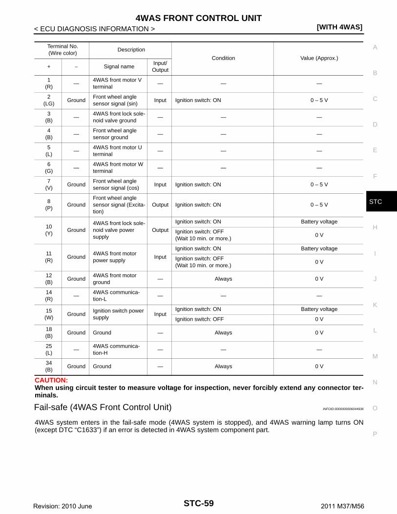
4WAS FRONT CONTROL UNIT[WITH 4WAS]
C
D
E
F
H
I
J
K
L
M
A
B
TC
N
O
P
< ECU DIAGNOSIS INFORMATION >
S
CAUTION:When using circuit tester to measure voltage for inspection, never forcibly extend any connector ter-minals.
Fail-safe (4WAS Front Control Unit) INFOID:0000000006044936
4WAS system enters in the fail-safe mode (4WAS system is stopped), and 4WAS warning lamp turns ON(except DTC “C1633”) if an error is detected in 4WAS system component part.
Terminal No.(Wire color)
Description
Condition Value (Approx.)
+ − Signal nameInput/Output
1(R)
—4WAS front motor V terminal
— — —
2(LG)
GroundFront wheel angle sensor signal (sin)
Input Ignition switch: ON 0 – 5 V
3(B)
—4WAS front lock sole-noid valve ground
— — —
4(B)
—Front wheel angle sensor ground
— — —
5(L)
—4WAS front motor U terminal
— — —
6(G)
—4WAS front motor W terminal
— — —
7(V)
GroundFront wheel angle sensor signal (cos)
Input Ignition switch: ON 0 – 5 V
8(P)
GroundFront wheel angle sensor signal (Excita-tion)
Output Ignition switch: ON 0 – 5 V
10(Y)
Ground4WAS front lock sole-noid valve power supply
Output
Ignition switch: ON Battery voltage
Ignition switch: OFF(Wait 10 min. or more.)
0 V
11(R)
Ground4WAS front motor power supply
Input
Ignition switch: ON Battery voltage
Ignition switch: OFF(Wait 10 min. or more.)
0 V
12(B)
Ground4WAS front motor ground
— Always 0 V
14(R)
—4WAS communica-tion-L
— — —
15(W)
GroundIgnition switch power supply
InputIgnition switch: ON Battery voltage
Ignition switch: OFF 0 V
18(B)
Ground Ground — Always 0 V
25(L)
—4WAS communica-tion-H
— — —
34(B)
Ground Ground — Always 0 V
STC-59Revision: 2010 June 2011 M37/M56

[WITH 4WAS]4WAS FRONT CONTROL UNIT
< ECU DIAGNOSIS INFORMATION >
*: Communication line between 4WAS front control unit and 4WAS main control unit
Protection Function (4WAS Front Control Unit) INFOID:0000000006044937
4WAS system enters in the protection function mode (4WAS system is temporarily stopped) if 4WAS systemcontinues the heavy load condition and the overheat condition.4WAS system reactivates automatically if theheavy load condition and the overheat condition are resolved.4WAS warning lamp continues turning OFF inthe protection function mode.
DTC Error area and root cause Contents of fail-safe
C16214WAS front motor current valve error is detected.(4WAS front motor current valve is excessively large.)
4WAS system is stopped.
C16224WAS front motor voltage valve or current error valve is detected.(4WAS front motor voltage valve error is detected.)(Voltage valve or current valve error is detected when starting the system.)
C1627The indication value from 4WAS front actuator (front wheel angle) differs from the value from 4WAS front control unit.
C1628 The front wheel steering angle sensor error is detected.
C1631 An error is detected inside 4WAS front control unit.
C1632 An error is detected inside 4WAS front control unit.
C1633 An error is detected inside 4WAS front control unit.
C1651 The ignition voltage signal error is detected.
C1652 4WAS front motor main power supply error is detected.
C1654 An error is detected on the main relay power supply inside 4WAS front control unit.
C16554WAS front motor 3-phase current error is detected.(Current is not applied to 4WAS front motor)
C16614WAS front lock solenoid valve error is detected.(An electric activation error is detected.)
C16674WAS front lock solenoid valve (lock) error is detected.(An error is detected in lock condition.)
C16684WAS front lock solenoid valve (lock) error is detected.(Excessive force is applied to the lock.)
C16694WAS front actuator error is detected.(An error is detected in unlock condition.)
C1671 4WAS front actuator adjustment is not performed.
C1672 4WAS front actuator adjustment is incomplete.
C16844WAS communication line* data communication error is detected.(An error signal is detected from 4WAS main control unit.)
C16854WAS communication line* data communication error is detected.(An error signal is detected from 4WAS main control unit.)
C1686An error is detected on 4WAS main control unit side.(4WAS main control unit fail-safe mode)
U1000When 4WAS front control unit is not transmitting or receiving 4WAS communication signal for 2 seconds or more.
U1002When 4WAS front control unit is not transmitting or receiving 4WAS communication signal for 2 seconds or less.
U1010When detecting error during the initial diagnosis of 4WAS controller of 4WAS front control unit
STC-60Revision: 2010 June 2011 M37/M56

4WAS FRONT CONTROL UNIT[WITH 4WAS]
C
D
E
F
H
I
J
K
L
M
A
B
TC
N
O
P
< ECU DIAGNOSIS INFORMATION >
S
DTC Inspection Priority Chart INFOID:0000000006044938
If some DTCs are displayed at the same time, perform inspections one by one based on the following prioritychart.
*: 4WAS communication
DTC Index INFOID:0000000006044939
DTC Error area and root cause Contents of protection function
— 4WAS front control unit power supply temporary malfunctioning condition
4WAS system is temporarily stopped.— 4WAS front control unit overheat condition
— 4WAS front actuator overheat condition
— 4WAS front control unit heavy load condition
Priority Detected items (DTC)
1• U1000 CANCOMM CIRCUIT*• U1002 SYSTEM COMM(CAN)*• U1010 CONTROL UNIT(CAN)*
2• C1671 ACT ADJ NOT PRFRM• C1672 INCOMP ACTUATR ADJ
3• C1631 CONTROL UNIT• C1632 CONTROL UNIT
4
• C1651 IGN POWER SUPPLY• C1652 MOTOR POWER SUPPLY• C1654 ACTUATOR RELAY• C1655 PRE-DRIVER
5
• C1621 ACTUATOR• C1622 ACTUATOR• C1627 ACTUATOR• C1628 ACTUATOR• C1661 LOCK SOLENOID• C1667 LOCK INSERTION• C1668 LOCK HLD GAP DETCT• C1669 INCOMP LOCK RELEAS
6• C1684 4WAS MAIN ECU COMM• C1685 4WAS MAIN ECU COMM• C1686 4WAS MAIN ECU
7 • C1633 CONTROL UNIT
DTC Display Items Reference
C1621 ACTUATOR STC-92, "DTC Logic"
C1622 ACTUATOR STC-92, "DTC Logic"
C1627 ACTUATOR STC-95, "DTC Logic"
C1628 ACTUATOR STC-96, "DTC Logic"
C1631 CONTROL UNIT STC-98, "DTC Logic"
C1632 CONTROL UNIT STC-98, "DTC Logic"
C1633 CONTROL UNIT STC-101, "DTC Logic"
C1651 IGN POWER SUPPLY STC-103, "DTC Logic"
C1652 MOTOR POWER SUPPLY STC-105, "DTC Logic"
C1654 ACTUATOR RELAY STC-107, "DTC Logic"
C1655 PRE-DRIVER STC-109, "DTC Logic"
C1661 LOCK SOLENOID STC-111, "DTC Logic"
STC-61Revision: 2010 June 2011 M37/M56
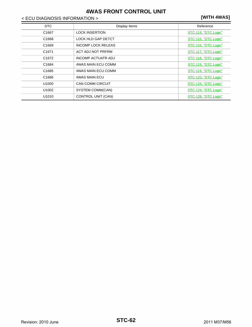
[WITH 4WAS]4WAS FRONT CONTROL UNIT
< ECU DIAGNOSIS INFORMATION >
C1667 LOCK INSERTION STC-113, "DTC Logic"
C1668 LOCK HLD GAP DETCT STC-115, "DTC Logic"
C1669 INCOMP LOCK RELEAS STC-116, "DTC Logic"
C1671 ACT ADJ NOT PRFRM STC-117, "DTC Logic"
C1672 INCOMP ACTUATR ADJ STC-118, "DTC Logic"
C1684 4WAS MAIN ECU COMM STC-119, "DTC Logic"
C1685 4WAS MAIN ECU COMM STC-119, "DTC Logic"
C1686 4WAS MAIN ECU STC-123, "DTC Logic"
U1000 CAN COMM CIRCUIT STC-124, "DTC Logic"
U1002 SYSTEM COMM(CAN) STC-124, "DTC Logic"
U1010 CONTROL UNIT (CAN) STC-128, "DTC Logic"
DTC Display Items Reference
STC-62Revision: 2010 June 2011 M37/M56

4WAS MAIN CONTROL UNIT[WITH 4WAS]
C
D
E
F
H
I
J
K
L
M
A
B
TC
N
O
P
< ECU DIAGNOSIS INFORMATION >
S
4WAS MAIN CONTROL UNIT
Reference Value INFOID:0000000006044940
VALUES ON THE DIAGNOSIS TOOL
Monitor item Condition Value/Status
VHCL SPEED SE
Vehicle stopped 0 km/h (0 MPH)
Start the engine. Wait a minute. Drive the vehicle.CAUTION:Check air pressure of tire under standard conditions.
Approximately equal to the indi-cation on speedometer (Inside of ±10%)
STEERING ANG
Steering wheel turned right Approx. 0 – R550°
Straight-ahead Approx. 0°
Steering wheel turned left Approx. 0 – L550°
ENGINE SPEED
Engine stopped 0 rpm
Engine running(Engine speed: 400 rpm or more)
Approximately equal to the indi-cation on tachometer
STR ANGL SPDThe steering wheel is not steered. 0 deg/s
The steering wheel is steering. 1 – 3,000 deg/s
POWER STR SOL
Vehicle speed: 0 km/h (0 MPH)(Engine is running)
Approx. 1.10 A
Vehicle speed: 100 km/h (62 MPH) Approx. 0.42 A
RR ST ANG-MAI
4WAS rear actuator turns right completely Approx. 4.4 V
4WAS rear actuator is neutral Approx. 2.4 V
4WAS rear actuator turns left completely Approx. 0.4 V
RR ST ANG-SUB
4WAS rear actuator turns right completely Approx. 4.4 V
4WAS rear actuator is neutral Approx. 2.6 V
4WAS rear actuator turns left completely Approx. 0.4 V
RR ST ANG-VOL Ignition switch: ON Approx. 5 V
C/U VOLTAGE Ignition switch: ON Battery voltage
MOTOR VOLTAGE Ignition switch: ON Battery voltage
MOTOR CURRENT 4WAS rear motor running 0 – 20 A
MTR CRNT OPE
4WAS rear actuator neutral condition and vehicle straight-ahead position.
Approx. (−2) – (+2) A
4WAS rear motor running Approx. (−20) – (+20) A
RR ANGLE OPE
4WAS rear actuator turned right Approx. 0 – 1 deg
4WAS rear actuator is neutral Approx. 0 deg
4WAS rear actuator turned left Approx. 0 – (−1) deg
FR ANGLE OPE
Steering wheel turned to the right (with vehicle stopped). Approx. 0 – R60°
Straight-ahead Approx. 0°
Steering wheel turned to the left (with vehicle stopped). Approx. 0 – L60°
STOP LAMP SWBrake pedal: Depressed On
Brake pedal: Released Off
HICAS RELAY Ignition switch: ON On
FAIL SAFEFail-safe condition On
Normal Off
WARNING LAMP4WAS warning lamp: ON On
4WAS warning lamp: OFF Off
STC-63Revision: 2010 June 2011 M37/M56

[WITH 4WAS]4WAS MAIN CONTROL UNIT
< ECU DIAGNOSIS INFORMATION >
TERMINAL LAYOUT
PHYSICAL VALUES
FRNT ECU FAIL4WAS front control unit fail-safe mode On
Normal Off
FRNT ECU EX4WAS front control unit enters in the protection function mode On
Normal Off
DRIVE MODE STAT
Drive mode select switch: STANDARD⇒SPORT
Steering wheel: Neutral STD⇒SP
Steering wheel: Except neutral STD
Drive mode select switch: SPORT⇒STANDARD
Steering wheel: Neutral SP⇒STD
Steering wheel: Except neutral SP
Monitor item Condition Value/Status
SGIA1449E
Terminal No.(Wire color)
Description
Condition Value (Approx.)
+ − Signal nameInput/Output
1(L)
— CAN-H — — —
4(R)
GroundRear wheel steering angle sensor (main) output voltage
Output
4WAS rear actuator assembly turns right completely.
4.4 V
4WAS rear actuator assembly is neutral 2.4 V
4WAS rear actuator assembly turns left completely.
0.4 V
5(V)
GroundRear wheel steering angle sensor power supply
OutputIgnition switch: ON 5 V
Ignition switch: OFF 0 V
7(LG)
GroundRear wheel steering angle sensor (sub) output voltage
Output
4WAS rear actuator assembly turns right completely.
4.6 V
4WAS rear actuator assembly is neutral 2.6 V
4WAS rear actuator assembly turns left completely.
0.6 V
8(P)
— CAN-L — — —
15(W)
GroundRear wheel steering angle sensor ground
— Always 0 V
22(P)
Ground Stop lamp switch InputBrake pedal: Depressed Battery voltage
Brake pedal: Released 0 V
25(G)
Ground4WAS rear motor re-lay
InputIgnition switch: ON Battery voltage
Ignition switch: OFF 0 V
STC-64Revision: 2010 June 2011 M37/M56

4WAS MAIN CONTROL UNIT[WITH 4WAS]
C
D
E
F
H
I
J
K
L
M
A
B
TC
N
O
P
< ECU DIAGNOSIS INFORMATION >
S
CAUTION:When using circuit tester to measure voltage for inspection, never forcibly extend any connector ter-minals.EPS SYSTEM
EPS SYSTEM : Fail-safe (4WAS Main Control Unit) INFOID:0000000006044941
• EPS system (4WAS main control unit) enters the fail-safe mode(that allows the steering force to be controlled without impairing thedrive ability) if the input from each sensor is not within the specifiedrange. Then, 4WAS warning lamp turns ON.
4WAS SYSTEM
27(R)
Ground Ignition switch InputIgnition switch: ON Battery voltage
Ignition switch: OFF 0 V
31(W/L)
—4WAS communica-tion-H
— — —
32(GR/V)
—4WAS communica-tion-L
— — —
34(B/Y)
Ground Ground — Always 0 V
36(SB)
GroundPower steering sole-noid valve
Output
Vehicle speed: 0 km/h (0 MPH)(Engine speed: 400 rpm or more)
4.4 – 6.6 V
Vehicle speed: 60 km/h (37 MPH) 1.4 – 3.6 V
37(L)
Ground4WAS rear motor power supply
InputIgnition switch: ON Battery voltage
Ignition switch: OFF 0 V
38(R)
Ground4WAS rear motor out-put voltage(right)
Output
While 4WAS rear motor activates right-ward
Battery voltage
While 4WAS rear motor activates left-ward
0 V
39(P)
Ground4WAS rear motor out-put voltage(left)
Output
While 4WAS rear motor activates right-ward
0 V
While 4WAS rear motor activates left-ward
Battery voltage
40(B/Y)
Ground4WAS rear motor ground
— Always 0 V
Terminal No.(Wire color)
Description
Condition Value (Approx.)
+ − Signal nameInput/Output
JPGIB0014GB
DTC Error part and root cause Contents of fail-safe
C1919Malfunction is detected in vehicle speed signal that is output from ABS actuator and electric unit (control unit) via CAN communication.(Improper signal inputs while driving.)
Allows the steering force to be controlled without impair-ing the drive ability.
STC-65Revision: 2010 June 2011 M37/M56

[WITH 4WAS]4WAS MAIN CONTROL UNIT
< ECU DIAGNOSIS INFORMATION >
4WAS SYSTEM : Fail-safe (4WAS Main Control Unit) INFOID:0000000006044942
4WAS system enters in the fail-safe mode (4WAS system stopped) and 4WAS warning lamp turns ON if anerror is detected in 4WAS system (4WAS main control unit) component part.
DTC Error area and root cause Contents of fail-safe
C1900 An error is detected inside 4WAS main control unit.
4WAS system stopped.
C1901 An error is detected inside 4WAS main control unit.
C19024WAS rear motor current error is detected.(4WAS rear motor current output direction differs.)
C19034WAS rear motor current error is detected.(Current is input to 4WAS main control unit if 4WAS main control unit output is “OFF”.)
C19044WAS rear motor current error is detected.(4WAS rear motor output is overcurrent.)
C1905 An error is detected inside 4WAS main control unit.
C1906 An error is detected inside 4WAS main control unit.
C1907 An error is detected inside 4WAS main control unit.
C1908 An error is detected inside 4WAS main control unit.
C1909 An error is detected inside 4WAS main control unit.
C19104WAS rear motor inside error is detected.(4WAS rear motor does not move or the rear wheel angle sensor does not change if 4WAS main control unit output is 14 A or more.)
C19114WAS rear motor voltage error is detected.(4WAS rear motor voltage is low.)
C19124WAS rear motor voltage error is detected.(Voltage is applied to 4WAS main motor when 4WAS main control unit output is “OFF”.)
C19134WAS rear motor current error is detected.(4WAS rear motor does not move or the rear wheel angle sensor output does not change when 4WAS main control unit output is 18 A or more, and 4WAS main motor output is low.)
C1914 The rear wheel angle sensor power supply error is detected.
C1915 The rear wheel angle sensor signal (main) error is detected.
C1916 If the rear wheel angle sensor signal (sub) error is detected.
C1917The rear wheel angle sensor signal (main and sub) error is detected.(The output signal value differs temporarily between main and sub.)
C1918The rear wheel angle sensor signal (main and sub) error is detected.(The output signal value differs between main and sub.)
C1919Malfunction is detected in vehicle speed signal that is output from ABS actuator and elec-tric unit (control unit) via CAN communication.(Improper signal inputs while driving.)
C1920Malfunction is detected in steering angle sensor signal that is output from steering angle sensor via CAN communication.(No transmission from the steering angle sensor)
C1921Malfunction is detected in engine speed signal that is output from ECM via CAN communication.(Improper signal is input engine speed.)
When DTC “C1921” is detect-ed before starting the engine.
When DTC “C1921” is detect-ed after starting the engine.
—
STC-66Revision: 2010 June 2011 M37/M56

4WAS MAIN CONTROL UNIT[WITH 4WAS]
C
D
E
F
H
I
J
K
L
M
A
B
TC
N
O
P
< ECU DIAGNOSIS INFORMATION >
S
*: Communication line between 4WAS front control unit and 4WAS main control unit
Protection Function (4WAS Main Control Unit) INFOID:0000000006044943
4WAS system enters in the protection function mode (4WAS system temporarily stopped) if 4WAS systemcontinues the heavy load condition or the sensor self-check condition. (4WAS system reactivates automati-cally if the heavy load condition and the self-check condition are resolved.) 4WAS warning lamp stays OFF inthe protection function mode.
DTC Inspection Priority Chart INFOID:0000000006044944
If some DTCs are displayed at the same time, perform inspections one by one based on the following prioritychart.
C1922 An error is detected inside 4WAS main control unit.
4WAS system stopped.
C1923Malfunction is detected in steering angle sensor signal that is output from steering angle sensor via CAN communication.[Steering angle sensor input signal error is detected when driving.]
C1924Driving continuously at 10 km (6 mile) or more while the steering angle sensor value is not L10° - R10°.(Not detected in 4WAS front control unit fail-safe mode)
C1925 An error is detected inside 4WAS main control unit.
C1926
Malfunction is detected in steering angle sensor signal that is output from steering angle sensor via CAN communication.(When improper signal inputs to steering angle sensor and steering angle sensor itself de-tects the malfunction)
C1927 An error is detected inside 4WAS main control unit.
C1928 An error is detected inside 4WAS main control unit.
C1930An error is detected on 4WAS front control unit side.(4WAS front control unit fail-safe mode)
C19314WAS communication line* data communication error is detected.(An error signal is detected from 4WAS front control unit.)
C1932If the steering angle sensor error is detected.(Steering angle sensor output value is abnormal.)
C1933 An error is detected inside 4WAS main control unit.
U1000When 4WAS main control unit is not transmitting or re-ceiving CAN communication signal for 2 seconds or more.
When 4WAS main control unit is not receiving following CAN communication signal.• Drive mode select switch
signal
Mode is fixed to the mode when a malfunction of drive mode selector occurs. The mode is fixed to STANDARD mode after ignition switch OFF→ ON.
When 4WAS main control unit is not receiving following CAN communication signal or 4WAS communication signal.• Steering angle sensor• Vehicle speed signal• Engine speed signal• 4WAS system control signal
4WAS system stopped.
U1010When detecting error during the initial diagnosis of CAN controller of 4WAS main control unit.
DTC Error area and root cause Contents of fail-safe
DTC Error area and root cause Contents of protection function
— 4WAS main control unit power supply temporary malfunctioning condition
4WAS system is temporarily stopped.— 4WAS system heavy load condition
— The sensor of 4WAS system is in self-check condition
STC-67Revision: 2010 June 2011 M37/M56

[WITH 4WAS]4WAS MAIN CONTROL UNIT
< ECU DIAGNOSIS INFORMATION >
DTC Index INFOID:0000000006044945
Priority Detected items (DTC)
1• U1000 CAN COMM• U1010 CONTROL UNIT (CAN)• C1931 4WAS FRONT ECU COMM
2
• C1900 CONTROL UNIT [ABNORMAL1]• C1901 CONTROL UNIT [ABNORMAL2]• C1905 CONTROL UNIT [ABNORMAL3]• C1906 CONTROL UNIT [ABNORMAL5]• C1907 CONTROL UNIT [ABNORMAL4]• C1908 CONTROL UNIT [ABNORMAL7]• C1909 CONTROL UNIT [ABNORMAL6]• C1922 CONTROL UNIT [ABNORMAL8]• C1925 AD CONVERTER • C1927 CONTROL UNIT [ABNORMAL5]• C1928 CONTROL UNIT [ABNORMAL9]• C1933 CONTROL UNIT
3
• C1902 MOTOR OUTPUT [REV CURRENT]• C1903 MOTOR OUTPUT [NO CURRENT]• C1904 MOTOR OUTPUT [OVERCURRENT]• C1910 MOTOR OUTPUT [MOTOR LOCK]• C1911 MOTOR VOLTAGE [LOW VOLTAGE]• C1912 MOTOR VOLTAGE [BAD OBSTRCT]• C1913 MOTOR OUTPUT [ABNORML SIG]• C1914 RR ST ANGLE SENSOR [ABNORML VOL]• C1915 RR ST ANGLE SENSOR [MAIN SIGNAL]• C1916 RR ST ANGLE SENSOR [SUB SIGNAL]• C1917 RR ST ANGLE SENSOR [OFFSET SIG1]• C1918 RR ST ANGLE SENSOR [OFFSET SIG2]
4
• C1919 VEHICLE SPEED SEN [NO SIGNAL]• C1920 STEERING ANGLE SEN [NO SIGNAL]• C1921 ENG REV SIGNAL• C1923 STEERING ANGLE SEN [NO CHANGE]• C1924 STEERING ANGLE SEN [NO NEUT STATE]• C1926 STEERING ANGLE SEN• C1932 STEERING ANGLE SEN
5 • C1930 4WAS FRONT ECU
DTCItems
(CONSULT-III screen terms)Reference
C1900CONTROL UNIT[ABNORMAL1]
STC-129, "DTC Logic"
C1901CONTROL UNIT[ABNORMAL2]
STC-129, "DTC Logic"
C1902MOTOR OUTPUT[REV CURRENT]
STC-131, "DTC Logic"
C1903MOTOR OUTPUT[NO CURRENT]
STC-131, "DTC Logic"
C1904MOTOR OUTPUT[OVERCURRENT]
STC-131, "DTC Logic"
C1905CONTROL UNIT[ABNORMAL3]
STC-134, "DTC Logic"
C1906CONTROL UNIT[ABNORMAL5]
STC-129, "DTC Logic"
C1907CONTROL UNIT[ABNORMAL4]
STC-129, "DTC Logic"
STC-68Revision: 2010 June 2011 M37/M56

4WAS MAIN CONTROL UNIT[WITH 4WAS]
C
D
E
F
H
I
J
K
L
M
A
B
TC
N
O
P
< ECU DIAGNOSIS INFORMATION >
S
C1908CONTROL UNIT[ABNORMAL7]
STC-134, "DTC Logic"
C1909CONTROL UNIT[ABNORMAL6]
STC-136, "DTC Logic"
C1910MOTOR OUTPUT[MOTOR LOCK]
STC-131, "DTC Logic"
C1911MOTOR VOLTAGE[LOW VOLTAGE]
STC-138, "DTC Logic"
C1912MOTOR VOLTAGE[BAD OBSTRCT]
STC-138, "DTC Logic"
C1913MOTOR OUTPUT[ABNORML SIG]
STC-131, "DTC Logic"
C1914RR ST ANGLE SENSOR[ABNORML VOL]
STC-142, "DTC Logic"
C1915RR ST ANGLE SENSOR[MAIN SIGNAL]
STC-145, "DTC Logic"
C1916RR ST ANGLE SENSOR[SUB SIGNAL]
STC-145, "DTC Logic"
C1917RR ST ANGLE SENSOR[OFFSET SIG1]
STC-148, "DTC Logic"
C1918RR ST ANGLE SENSOR[OFFSET SIG2]
STC-148, "DTC Logic"
C1919VEHICLE SPEED SEN[NO SIGNAL]
STC-151, "DTC Logic"
C1920STEERING ANGLE SEN[NO SIGNAL]
STC-153, "DTC Logic"
C1921 ENG REV SIGNAL STC-155, "DTC Logic"
C1922CONTROL UNIT[ABNORMAL8]
STC-134, "DTC Logic"
C1923STEERING ANGLE SEN[NO CHANGE]
STC-157, "DTC Logic"
C1924STEERING ANGLE SEN[NO NEUT STATE]
STC-159, "DTC Logic"
C1925 AD CONVERTER STC-134, "DTC Logic"
C1926 STEERING ANGLE SEN STC-161, "DTC Logic"
C1927CONTROL UNIT[ABNORMAL5]
STC-129, "DTC Logic"
C1928CONTROL UNIT[ABNORMAL9]
STC-134, "DTC Logic"
C1930 4WAS FRONT ECU STC-163, "DTC Logic"
C1931 4WAS FRONT ECU COMM STC-164, "DTC Logic"
C1932 STEERING ANGLE SEN STC-161, "DTC Logic"
C1933 CONTROL UNIT STC-129, "DTC Logic"
U1000 CAN COMM STC-168, "Description"
U1010 CONTROL UNIT (CAN) STC-169, "DTC Logic"
DTCItems
(CONSULT-III screen terms)Reference
STC-69Revision: 2010 June 2011 M37/M56

[WITH 4WAS]4WAS SYSTEM
< WIRING DIAGRAM >
WIRING DIAGRAM4WAS SYSTEM
Wiring Diagram INFOID:0000000006044946
JCGWA0264GB
STC-70Revision: 2010 June 2011 M37/M56

4WAS SYSTEM[WITH 4WAS]
C
D
E
F
H
I
J
K
L
M
A
B
TC
N
O
P
< WIRING DIAGRAM >
S
JCGWA0265GB
STC-71Revision: 2010 June 2011 M37/M56

[WITH 4WAS]4WAS SYSTEM
< WIRING DIAGRAM >
JCGWA0266GB
STC-72Revision: 2010 June 2011 M37/M56

4WAS SYSTEM[WITH 4WAS]
C
D
E
F
H
I
J
K
L
M
A
B
TC
N
O
P
< WIRING DIAGRAM >
S
JCGWA0267GB
STC-73Revision: 2010 June 2011 M37/M56
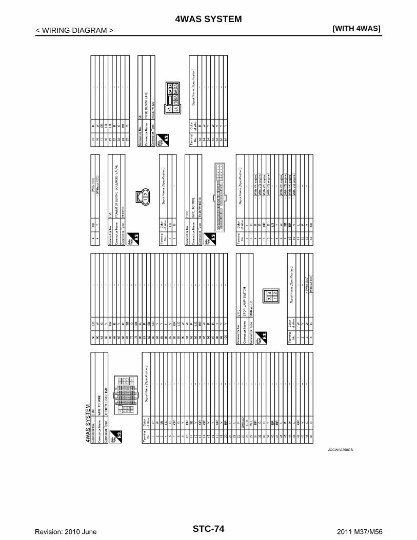
[WITH 4WAS]4WAS SYSTEM
< WIRING DIAGRAM >
JCGWA0268GB
STC-74Revision: 2010 June 2011 M37/M56

4WAS SYSTEM[WITH 4WAS]
C
D
E
F
H
I
J
K
L
M
A
B
TC
N
O
P
< WIRING DIAGRAM >
S
JCGWA0269GB
STC-75Revision: 2010 June 2011 M37/M56

[WITH 4WAS]4WAS SYSTEM
< WIRING DIAGRAM >
JCGWA0270GB
STC-76Revision: 2010 June 2011 M37/M56

4WAS SYSTEM[WITH 4WAS]
C
D
E
F
H
I
J
K
L
M
A
B
TC
N
O
P
< WIRING DIAGRAM >
S
JCGWA0271GB
STC-77Revision: 2010 June 2011 M37/M56

[WITH 4WAS]4WAS SYSTEM
< WIRING DIAGRAM >
JCGWA0272GB
STC-78Revision: 2010 June 2011 M37/M56

4WAS SYSTEM[WITH 4WAS]
C
D
E
F
H
I
J
K
L
M
A
B
TC
N
O
P
< WIRING DIAGRAM >
S
JCGWA0273GB
STC-79Revision: 2010 June 2011 M37/M56

[WITH 4WAS]4WAS SYSTEM
< WIRING DIAGRAM >
JCGWA0274GB
STC-80Revision: 2010 June 2011 M37/M56

DIAGNOSIS AND REPAIR WORK FLOW[WITH 4WAS]
C
D
E
F
H
I
J
K
L
M
A
B
TC
N
O
P
< BASIC INSPECTION >
S
BASIC INSPECTIONDIAGNOSIS AND REPAIR WORK FLOW
Work Flow INFOID:0000000006044947
DETAILED FLOW
1.INTERVIEW FROM THE CUSTOMER
Clarify customer complaints before inspection. First of all, perform an interview utilizing STC-83, "DiagnosticWork Sheet" and reproduce symptoms as well as fully understand it. Ask customer about his/her complaintscarefully. Check symptoms by driving vehicle with customer, if necessary.CAUTION:Customers are not professional. Never guess easily like “maybe the customer means that...,” or“maybe the customer mentions this symptom”.
>> GO TO 2.
2.CHECK SYMPTOM
Reproduce the symptom that is indicated by the customer, based on the information from the customerobtained by interview. Also check that the symptom is not caused by protection function. Refer to STC-60,"Protection Function (4WAS Front Control Unit)", STC-67, "Protection Function (4WAS Main Control Unit)".CAUTION:When the symptom is caused by normal operation, fully inspect each portion and obtain the under-standing of customer that the symptom is not caused by a malfunction.
>> GO TO 3.
3.CHECK CURRENT STATE
Start the engine.CAUTION:Never drive the vehicle.Does 4WAS warning lamp turn ON?YES >> GO TO 4.NO >> GO TO 12.
4.PERFORM SELF-DIAGNOSIS (4WAS MAIN CONTROL UNIT)
With CONSULT-IIIPerform self-diagnosis for “4WAS(MAIN)/RAS/HICAS”.Is DTC except “C1930” or “C1931” detected?YES >> GO TO 8.NO >> Record or print self-diagnosis results. GO TO 5.
5.RECHECK SYMPTOM (4WAS FRONT CONTROL UNIT)
With CONSULT-III1. Turn the ignition switch OFF, and then wait for 10 seconds or more.2. Perform self-diagnosis for “4WAS(FRONT)”.3. Record the values of “DATA MONITOR” about each DTC detected when performing self-diagnosis.4. Record the values of “FREEZE FRAME DATA” about each DTC detected when performing self-diagnosis.5. Erase self-diagnostic results for “4WAS(FRONT)”.
CAUTION:• Never erase the self-diagnostic results (records) history when replacing 4WAS front control unit.• Erase the memory of self-diagnostic results (records) after printing out or recording all the val-
ues of “DATA MONITOR”.6. Perform DTC confirmation procedures for the error detected system.
NOTE:• If some DTCs are detected at the same time, determine the order for performing the diagnosis based on
STC-61, "DTC Inspection Priority Chart".
STC-81Revision: 2010 June 2011 M37/M56

[WITH 4WAS]DIAGNOSIS AND REPAIR WORK FLOW
< BASIC INSPECTION >• IF DTC is not detected, refer to the recorded values of “FREEZE FRAME DATA”.
Is any DTC detected?YES >> GO TO 6.NO >> Check harness and connectors based on the information obtained by interview. Refer to GI-38,
"Intermittent Incident".
6.REPAIR OR REPLACE ERROR-DETECTED PARTS
1. Repair or replace error-detected parts.CAUTION:Reconnect part or connector after repairing or replacing.
2. When DTC is detected, erase self-diagnostic results for “4WAS(FRONT)”.
>> GO TO 7.
7.RECHECK SYMPTOM (4WAS FRONT CONTROL UNIT)
With CONSULT-IIIPerform DTC confirmation procedures for the error detected system.NOTE:• If some DTCs are detected at the same time, determine the order for performing the diagnosis based on
STC-61, "DTC Inspection Priority Chart".• IF DTC is not detected, refer to the recorded values of “FREEZE FRAME DATA”.Is any DTC detected?YES >> GO TO 6.NO >> GO TO 8.
8.PERFORM SELF-DIAGNOSIS (4WAS MAIN CONTROL UNIT)
With CONSULT-IIIPerform self-diagnosis for “4WAS(MAIN)/RAS/HICAS”.Is any DTC detected?YES >> Record or print self-diagnosis results. GO TO 9.NO >> GO TO 12.
9.RECHECK SYMPTOM (4WAS MAIN CONTROL UNIT)
With CONSULT-III1. Turn the ignition switch OFF, and then wait for 10 seconds or more.2. Record the values of “DATA MONITOR” about each DTC detected when performing self-diagnosis.3. Record the values of “FREEZE FRAME DATA” about each DTC detected when performing self-diagnosis.4. Erase self-diagnostic results for “4WAS(MAIN)/RAS/HICAS”.
CAUTION:• Never erase the self-diagnostic results (records) history when replacing 4WAS main control unit.• Erase the memory of self-diagnostic results (records) after printing out or recording all the val-
ues of “DATA MONITOR”.5. Perform DTC confirmation procedures for the error detected system.
NOTE:• If some DTCs are detected at the same time, determine the order for performing the diagnosis based on
STC-67, "DTC Inspection Priority Chart".• IF DTC is not detected, refer to the recorded values of “FREEZE FRAME DATA”.
Is any DTC detected?YES >> GO TO 10.NO >> Check harness and connectors based on the information obtained by interview. Refer to GI-41,
"Circuit Inspection".
10.REPAIR OR REPLACE ERROR-DETECTED PARTS
1. Repair or replace error-detected parts.CAUTION:Reconnect part or connector after repairing or replacing.
2. When DTC is detected, erase self-diagnostic results for “4WAS(MAIN)/RAS/HICAS”.
STC-82Revision: 2010 June 2011 M37/M56

DIAGNOSIS AND REPAIR WORK FLOW[WITH 4WAS]
C
D
E
F
H
I
J
K
L
M
A
B
TC
N
O
P
< BASIC INSPECTION >
S
>> GO TO 11.
11.RECHECK SYMPTOM (4WAS MAIN CONTROL UNIT)
With CONSULT-IIIPerform DTC confirmation procedures for the error detected system.NOTE:• If some DTCs are detected at the same time, determine the order for performing the diagnosis based on
STC-67, "DTC Inspection Priority Chart".• IF DTC is not detected, refer to the recorded values of “FREEZE FRAME DATA”.Is any DTC detected?YES >> GO TO 10.NO >> GO TO 13.
12.IDENTIFY ERROR-DETECTED SYSTEM BY SYMPTOM DIAGNOSIS
Estimate error-detected system based on symptom diagnosis and perform inspection.Can the error-detected system be identified?YES >> GO TO 13.NO >> Check harness and connectors based on the information obtained by interview. Refer to GI-38,
"Intermittent Incident".
13.FINAL CHECK
With CONSULT-III1. Check the reference value for 4WAS front control unit and 4WAS main control unit.2. Recheck the symptom and check that symptom is not reproduced on the same conditions.Is the symptom reproduced?YES >> GO TO 4.NO >> INSPECTION END
Diagnostic Work Sheet INFOID:0000000006044948
Description• In general, customers have their own criteria for a problem. Therefore, it is important to understand the
symptom and status well enough by asking the customer about his/her concerns carefully. To systemize allthe information for the diagnosis, prepare the interview sheet referring to the interview points.
• In some cases, multiple conditions that appear simultaneously may cause a DTC to be detected.
Interview sheet sample
Interview sheet
Customer name
MR/MS
Registration number
Initial year registration
Vehicle type VIN
Storage date Engine Mileage km (Mile)
Symptom
The steering wheel position (center) is in the wrong position.
4WAS warning lamp turns on.
Noise Vibration
Others( )
First occurrence Recently Others ( )
Frequency of occurrence Always Under a certain conditions of Sometimes (time(s)/day)
Climate con-ditions
Irrelevant
Weather Fine Cloud Rain Snow Others ( )
Temperature Hot Warm Cool Cold Temperature (Approx. °C)
Relative humidity High Moderate Low
STC-83Revision: 2010 June 2011 M37/M56

[WITH 4WAS]DIAGNOSIS AND REPAIR WORK FLOW
< BASIC INSPECTION >
Road conditionsUrban area Suburb area High wayMounting road (uphill or down hill) Rough road
Operation conditions, etc.
IrrelevantWhen engine starts During idlingDuring driving During acceleration At constant speed drivingDuring deceleration During cornering (right curve or left curve)During steering
Other conditions
Memo
Interview sheet
Customer name
MR/MS
Registration number
Initial year registration
Vehicle type VIN
Storage date Engine Mileage km (Mile)
STC-84Revision: 2010 June 2011 M37/M56

ADDITIONAL SERVICE WHEN REPLACING 4WAS FRONT CONTROL UNIT[WITH 4WAS]
C
D
E
F
H
I
J
K
L
M
A
B
TC
N
O
P
< BASIC INSPECTION >
S
ADDITIONAL SERVICE WHEN REPLACING 4WAS FRONT CONTROLUNIT
Description INFOID:0000000006044949
When replacing 4WAS front control unit, 4WAS front actuator adjustment is required.CAUTION:• Never erase the memory (history) of self-diagnosis results when replacing 4WAS front control unit
after diagnosis.• Erase the memory of the self-diagnosis results (record) after printing out or recording all the values
of “DATA MONITOR”.
Work Procedure INFOID:0000000006136316
1.PERFORM 4WAS FRONT ACTUATOR ADJUSTMENT
Perform 4WAS front actuator adjustment.
>> Refer to STC-88, "Work Procedure (Pattern 3)".
STC-85Revision: 2010 June 2011 M37/M56

[WITH 4WAS]ADDITIONAL SERVICE WHEN REPLACING 4WAS MAIN CONTROL UNIT
< BASIC INSPECTION >
ADDITIONAL SERVICE WHEN REPLACING 4WAS MAIN CONTROL UNIT
Description INFOID:0000000006134048
Before replacing 4WAS main control unit, record the sele-diagnosis results (history).CAUTION:• Never erase the memory (history) of self-diagnosis results when replacing 4WAS main control unit
after diagnosis.• Erase the memory of the self-diagnosis results (record) after printing out or recording all the values
of “DATA MONITOR”.
STC-86Revision: 2010 June 2011 M37/M56

4WAS FRONT ACTUATOR NEUTRAL POSITION ADJUSTMENT[WITH 4WAS]
C
D
E
F
H
I
J
K
L
M
A
B
TC
N
O
P
< BASIC INSPECTION >
S
4WAS FRONT ACTUATOR NEUTRAL POSITION ADJUSTMENT
Description INFOID:0000000006044950
4WAS front actuator adjustment is required when performing any service below.• 4WAS front actuator and the steering components (including wheel alignment) removal. Refer to STC-87,
"Work Procedure (Pattern 1)".CAUTION:• Check the following items before the removal:- 4WAS warning lamp OFF after the engine starts.- Self-diagnosis of each control unit of 4WAS system (4WAS front control unit/4WAS main control
unit) is performed. Check that 4WAS system controlled properly.• 4WAS front actuator and the steering components (including wheel alignment) installation. Refer to STC-87,
"Work Procedure (Pattern 2)".• 4WAS front control unit and the steering angle sensor replacement. Refer to STC-88, "Work Procedure (Pat-
tern 3)".• When driving while misaligning the steering wheel position (center) after installing 4WAS front actuator.
Refer to STC-89, "Work Procedure (Pattern 4)".
Work Procedure (Pattern 1) INFOID:0000000006044951
1.4WAS FRONT ACTUATOR ADJUSTMENT
With CONSULT-III1. Start the engine.
CAUTION:Never drive the vehicle.
2. Turn the steering wheel to adjust “ACTR ROTA ANG” of the 4WAS front control unit “DATA MONITOR” sothat it falls within the range shown below:
3. Turn the ignition switch OFF.CAUTION:Never touch the steering wheel after turning ignition switch OFF.
>> END
Work Procedure (Pattern 2) INFOID:0000000006044952
1.4WAS FRONT ACTUATOR ADJUSTMENT
With CONSULT-III1. Turn the ignition switch ON.
CAUTION:Never start the engine.
2. Steer 30° leftward slowly. Steer 30° rightward and return the steering wheel to the straight-ahead position.3. Perform the steering angle sensor neutral position adjustment. Refer to BRC-68, "Work Procedure".4. Turn the ignition switch OFF.
>> GO TO 2.
2.PERFORM ACTIVE TEST (SLOW MODE)
With CONSULT-III1. Start the engine.
CAUTION:Never drive the vehicle.
2. Select “SLOW MODE” item on “ACTIVE TEST” for “4WAS(FRONT)”.3. Perform “MODE START” of “ACTIVE TEST”.4. Steer the steering wheel leftward slowly until the turning stops.5. Steer the steering wheel rightward slowly until the turning stops.
ACTR ROTA ANG : (−3.5) – (+3.5) deg
STC-87Revision: 2010 June 2011 M37/M56

[WITH 4WAS]4WAS FRONT ACTUATOR NEUTRAL POSITION ADJUSTMENT
< BASIC INSPECTION >Is “OK” indicated on both right and left on “SLOW MODE”?YES >> GO TO 3.NO >> Refer to STC-89, "Work Procedure (Pattern 4)".
3.PERFORM SELF-DIAGNOSIS (4WAS FRONT CONTROL UNIT)
With CONSULT-IIIPerform self-diagnosis for “4WAS(FRONT)”.NOTE:Detect DTC “C1671” when replacing 4WAS front control unit or performing 4WAS front actuator adjustment.DTC “C1671” becomes past record if 4WAS front actuator adjustment is completed normally.Is any error system detected?YES >> Check the error system.NO >> GO TO 4.
4.ERASE ERROR HISTORY
With CONSULT-IIIErase the memory of self-diagnostic result for “4WAS(FRONT)” and “4WAS(MAIN)/RAS/HICAS”.
>> END
Work Procedure (Pattern 3) INFOID:0000000006044953
1.PERFORM ACTIVE TEST (LOCK OPERATION)
With CONSULT-III1. Never drive the vehicle to the straight-ahead position.2. Turn the ignition switch ON.
CAUTION:Never start the engine.
3. Select “LOCK OPERATION” item on “ACTIVE TEST” for “4WAS(FRONT)”.4. Perform “RELEASE” of “ACTIVE TEST”.
CAUTION:• Turn the steering wheel 90°. Check that the front wheels do not move.• Never turn the steering wheel during “RELEASE”.
5. Turn the steering wheel to adjust “4WAS STR ANG” of “DATA MONITOR” for “4WAS(FRONT)” so that itfalls within the range shown below:
6. Perform “LOCK” item on “ACTIVE TEST” for “4WAS(FRONT)”.7. Steer 30° leftward slowly. Steer 30° rightward and return the steering wheel to the straight-ahead position.8. Finish 4WAS front control unit active test.
>> GO TO 2.
2.STEERING ANGLE SENSOR NEUTRAL POSITION ADJUSTMENT
1. Perform the steering angle sensor neutral position adjustment. Refer to BRC-68, "Work Procedure".2. Turn the ignition switch OFF.
>> GO TO 3.
3.RETURN TO 4WAS FRONT ACTUATOR INITIAL POSITION
1. Start the engine.CAUTION:Never drive the vehicle.
2. Steer 90° leftward slowly. Then steer 90° rightward.3. Steer 90° leftward slowly again. Then steer 90° rightward. Return the steering wheel to the straight-ahead
position.4. Stop the vehicle in the straight-ahead position after driving for a period of time. (When engine is running)
4WAS STR ANG : (−3.5) – (+3.5) deg
STC-88Revision: 2010 June 2011 M37/M56

4WAS FRONT ACTUATOR NEUTRAL POSITION ADJUSTMENT[WITH 4WAS]
C
D
E
F
H
I
J
K
L
M
A
B
TC
N
O
P
< BASIC INSPECTION >
S
>> GO TO 4.
4.CHECK 4WAS FRONT ACTUATOR INSPECTION
With CONSULT-III1. Check “4WAS STR ANG” item on “DATA MONITOR” for “4WAS(FRONT)”.
CAUTION:Never touch the steering wheel during the service.
2. Turn the ignition switch OFF.Is the inspection result normal?YES >> GO TO 5.NO >> GO TO 1.
5.PERFORM ACTIVE TEST (SLOW MODE)
With CONSULT-III1. Start the engine.
CAUTION:Never drive the vehicle.
2. Select “SLOW MODE” item on “ACTIVE TEST” for “4WAS(FRONT)”.3. Perform “MODE START” of “ACTIVE TEST”.4. Steer the steering wheel leftward slowly until the turning stops.5. Steer the steering wheel rightward slowly until the turning stops.Is “OK” indicated on both right and left on “SLOW MODE”?YES >> GO TO 6.NO >> Refer to STC-89, "Work Procedure (Pattern 4)".
6.PERFORM SELF-DIAGNOSIS (4WAS FRONT CONTROL UNIT)
With CONSULT-IIIPerform self-diagnosis for “4WAS(FRONT)”.Is any error system detected?YES >> Check the error system.NO >> GO TO 7.
7.ERASE ERROR HISTORY
With CONSULT-IIIErase the memory of self-diagnostic result for “4WAS(FRONT)” and “4WAS(MAIN)/RAS/HICAS”.
>> END
Work Procedure (Pattern 4) INFOID:0000000006044954
1.CHECK 4WAS FRONT ACTUATOR
1. Never drive the vehicle to the straight-ahead position.2. Remove and install 4WAS front actuator again. Check the installation condition.3. Check that the steering wheel is neutral.
>> GO TO 2.
2.PERFORM ACTIVE TEST (LOCK OPERATION)
With CONSULT-III1. Stop the vehicle to the straight-ahead position.2. Turn the ignition switch ON.
CAUTION:Never start the engine.
3. Select “LOCK OPERATION” item on “ACTIVE TEST” for “4WAS(FRONT)”.
4WAS STR ANG : (−3.5) – (+3.5) deg
STC-89Revision: 2010 June 2011 M37/M56

[WITH 4WAS]4WAS FRONT ACTUATOR NEUTRAL POSITION ADJUSTMENT
< BASIC INSPECTION >4. Perform “RELEASE” of “ACTIVE TEST”.
CAUTION:• Turn the steering wheel 90°. Check that the front wheels do not move.• Never turn the steering wheel during “RELEASE”.
5. Turn the steering wheel to adjust “4WAS STR ANG” of “DATA MONITOR” for “4WAS(FRONT)” so that itfalls within the range shown below:
6. Perform “LOCK” item on “ACTIVE TEST” for “4WAS(FRONT)”.7. Finish 4WAS front control unit active test.
>> GO TO 3.
3.STEERING ANGLE SENSOR NEUTRAL POSITION ADJUSTMENT
1. Perform the steering angle sensor neutral position adjustment. Refer to BRC-68, "Work Procedure".2. Turn the ignition switch OFF.
>> GO TO 4.
4.RETURN TO 4WAS FRONT ACTUATOR INITIAL POSITION
1. Start the engine.CAUTION:Never drive the vehicle.
2. Steer 90° leftward slowly. Then steer 90° rightward.3. Steer 90° leftward slowly again. Then steer 90° rightward. Return the steering wheel to the straight-ahead
position.4. Stop the vehicle in the straight-ahead position after driving for a period of time. (Engine running)
>> GO TO 5.
5.CHECK 4WAS FRONT ACTUATOR
With CONSULT-III1. Check “4WAS STR ANG” item on “DATA MONITOR” for “4WAS(FRONT)”.
CAUTION:Never touch the steering wheel during the service.
2. Turn the ignition switch OFF.Is the inspection result normal?YES >> GO TO 6.NO >> GO TO 1.
6.PERFORM ACTIVE TEST (SLOW MODE)
With CONSULT-III1. Start the engine.
CAUTION:Never drive the vehicle.
2. Select “SLOW MODE” item on “ACTIVE TEST” for “4WAS(FRONT)”.3. Perform “MODE START” of “ACTIVE TEST”.4. Steer the steering wheel leftward slowly until the turning stops.5. Steer the steering wheel rightward slowly until the turning stops.Is “OK” indicated on both right and left on “SLOW MODE”?YES >> GO TO 7.NO >> GO TO 1.
7.PERFORM SELF-DIAGNOSIS (4WAS FRONT CONTROL UNIT)
With CONSULT-III
4WAS STR ANG : (−3.5) – (+3.5) deg
4WAS STR ANG : (−3.5) – (+3.5) deg
STC-90Revision: 2010 June 2011 M37/M56

4WAS FRONT ACTUATOR NEUTRAL POSITION ADJUSTMENT[WITH 4WAS]
C
D
E
F
H
I
J
K
L
M
A
B
TC
N
O
P
< BASIC INSPECTION >
S
Perform self-diagnosis for “4WAS(FRONT)”.Is any error system detected?YES >> Check the error system.NO >> GO TO 8.
8.ERASE ERROR HISTORY
With CONSULT-IIIErase the memory of self-diagnostic result for “4WAS(FRONT)” and “4WAS(MAIN)/RAS/HICAS”.
>> END
STC-91Revision: 2010 June 2011 M37/M56

[WITH 4WAS]C1621, C1622 4WAS FRONT ACTUATOR
< DTC/CIRCUIT DIAGNOSIS >
DTC/CIRCUIT DIAGNOSISC1621, C1622 4WAS FRONT ACTUATOR
DTC Logic INFOID:0000000006044955
DTC DETECTION LOGIC
DTC CONFIRMATION PROCEDURE
1.RECHECK DTC
With CONSULT-III1. Start the engine.
CAUTION:Never drive the vehicle.
2. Steer 360° leftward slowly. Then steer 360° rightward to return the steering wheel to the straight-aheadposition. Repeat the same service for 1 minute or more.NOTE:The protection function mode (overheat protection) activates and the system stops if steering repeats for along time.
3. Perform self-diagnosis for “4WAS(FRONT)”.Is DTC “C1621” or “C1622” detected?YES >> Proceed to diagnosis procedure. Refer to STC-92, "Diagnosis Procedure".NO >> INSPECTION END
Diagnosis Procedure INFOID:0000000006044956
1.CHECK 4WAS FRONT MOTOR CIRCUIT
Check 4WAS front motor circuit. Refer to STC-93, "Component Inspection (4WAS Front Motor)".Is the inspection result normal?YES >> GO TO 2.NO >> Replace 4WAS front actuator. Refer to ST-41, "WITH 4WAS : Removal and Installation".
2.CHECK 4WAS FRONT MOTOR CIRCUIT
1. Turn the ignition switch OFF.2. Disconnect 4WAS front actuator harness connector.3. Disconnect 4WAS front control unit harness connector.4. Check the continuity between 4WAS front actuator harness connector and 4WAS front control unit har-
ness connector.
Is the inspection result normal?
DTC Display Item Malfunction detected condition Possible cause
C1621 ACTUATOR4WAS front motor current valve error is detected.(4WAS front motor current valve is excessively large.)
4WAS front control unit or 4WAS front motor error is detected.
C1622 ACTUATOR
4WAS front motor voltage valve or current error valve is detected.(4WAS front motor voltage valve error is detected.)(Voltage valve or current valve error is detected when starting the system.)
4WAS front control unit or 4WAS front motor error is detected.
4WAS front actuator 4WAS front control unitContinuity
Connector Terminal Connector Terminal
M301
1
M300
1
Existed7 5
8 6
STC-92Revision: 2010 June 2011 M37/M56

C1621, C1622 4WAS FRONT ACTUATOR[WITH 4WAS]
C
D
E
F
H
I
J
K
L
M
A
B
TC
N
O
P
< DTC/CIRCUIT DIAGNOSIS >
S
YES >> GO TO 3.NO >> Repair or replace error-detected parts.
3.PERFORM SELF-DIAGNOSIS (4WAS FRONT CONTROL UNIT)
With CONSULT-III1. Connect 4WAS front actuator harness connector.2. Connect 4WAS front control unit harness connector.3. Turn the ignition switch OFF to ON.4. Perform self-diagnosisfor “4WAS(FRONT)”.Is DTC “C1621” or “C1622” detected?YES >> Replace 4WAS front control unit. Refer to STC-184, "Removal and Installation".
• Before replacing 4WAS front control unit, record the self-diagnosis results (histry). Refer toSTC-93, "Special Repair Requirement".
NO >> GO TO 4.
4.CHECK INFORMATION
With CONSULT-IIICheck the “DATA MONITOR” value of each DTC detected with the self-diagnosis function. Refer to STC-56,"Reference Value".Is each data the standard value?YES >> Check each harness connector pin terminal for disconnection.NO >> Replace 4WAS front control unit. Refer to STC-184, "Removal and Installation".
• Before replacing 4WAS front control unit, record the self-diagnosis results (histry). Refer toSTC-93, "Special Repair Requirement".
Component Inspection (4WAS Front Motor) INFOID:0000000006044957
1.CHECK 4WAS FRONT MOTOR
1. Turn the ignition switch OFF.2. Disconnect 4WAS front actuator harness connector.3. Check the resistance between 4WAS front actuator harness connectors.
4. Check the continuity between 4WAS front actuator harness connector and the ground.
Is the inspection result normal?YES >> INSPECTION ENDNO >> Replace 4WAS front actuator. Refer to ST-41, "WITH 4WAS : Removal and Installation".
Special Repair Requirement INFOID:0000000006136321
Before replacing 4WAS front control unit, record the self-diagnosis results (history).CAUTION:• Never erase the memory (history) of self-diagnosis results when replacing 4WAS front control unit
after diagnosis.
4WAS front actuatorResistance (Approx.)
Terminal
1 7
0.1 – 1 Ω1 8
7 8
4WAS front actuatorContinuity
Terminal
1 – Ground
Not existed7 – Ground
8 – Ground
STC-93Revision: 2010 June 2011 M37/M56

[WITH 4WAS]C1621, C1622 4WAS FRONT ACTUATOR
< DTC/CIRCUIT DIAGNOSIS >• Erase the memory of the self-diagnosis results (record) after printing out or recording all the values
of “DATA MONITOR”.
STC-94Revision: 2010 June 2011 M37/M56

C1627 4WAS FRONT ACTUATOR[WITH 4WAS]
C
D
E
F
H
I
J
K
L
M
A
B
TC
N
O
P
< DTC/CIRCUIT DIAGNOSIS >
S
C1627 4WAS FRONT ACTUATOR
DTC Logic INFOID:0000000006044959
DTC DETECTION LOGIC
DTC CONFIRMATION PROCEDURE
1.RECHECK DTC
With CONSULT-III1. Start the engine.
CAUTION:Never drive the vehicle.
2. Steer 360° leftward slowly. Then steer 360° rightward to return the steering wheel to the straight-aheadposition. Repeat the same service for 1 minute or more.NOTE:The protection function mode (overheat protection) activates and the system stops if steering repeats for along time.
3. Perform self-diagnosis for “4WAS(FRONT)”.Is DTC “C1627” detected?YES >> Proceed to diagnosis procedure. Refer to STC-95, "Diagnosis Procedure".NO >> INSPECTION END
Diagnosis Procedure INFOID:0000000006044960
1.PERFORM SELF-DIAGNOSIS (4WAS FRONT CONTROL UNIT)
With CONSULT-IIIPerform self-diagnosis for “4WAS(FRONT)”.Is any DTC detected other than “C1627”?YES >> Check the error system.NO >> GO TO 2.
2.PERFORM SELF-DIAGNOSIS (4WAS FRONT CONTROL UNIT)
With CONSULT-IIIPerform self-diagnosis for “4WAS(FRONT)”.Is DTC “C1627” detected?YES >> Replace 4WAS front actuator. Refer to ST-41, "WITH 4WAS : Removal and Installation".NO >> GO TO 3.
3.CHECK INFORMATION
With CONSULT-IIICheck the “DATA MONITOR” value of each DTC detected with the self-diagnosis function. Refer to STC-56,"Reference Value".Is each data the standard value?YES >> Check each harness connector pin terminal for disconnection.NO >> Replace 4WAS front actuator. Refer to STC-184, "Removal and Installation".
DTC Display Item Malfunction detected condition Possible cause
C1627 ACTUATORThe indication value from 4WAS front actuator (front wheel angle) differs from the value from 4WAS front control unit.
4WAS front actuator error
STC-95Revision: 2010 June 2011 M37/M56

[WITH 4WAS]C1628 4WAS FRONT ACTUATOR
< DTC/CIRCUIT DIAGNOSIS >
C1628 4WAS FRONT ACTUATOR
DTC Logic INFOID:0000000006044962
DTC DETECTION LOGIC
DTC CONFIRMATION PROCEDURE
1.RECHECK DTC
With CONSULT-III1. Start the engine.
CAUTION:Never drive the vehicle.
2. Steer 360° leftward slowly. Then steer 360° rightward to return the steering wheel to the straight-aheadposition. Repeat the same service for 1 minute or more.NOTE:The protection function mode (overheat protection) activates and the system stops if steering repeats for along time.
3. Perform self-diagnosis for “4WAS(FRONT)”.Is DTC “C1628” detected?YES >> Proceed to diagnosis procedure. Refer to STC-96, "Diagnosis Procedure".NO >> INSPECTION END
Diagnosis Procedure INFOID:0000000006044963
1.CHECK FRONT WHEEL STEERING ANGLE SENSOR CIRCUIT (1)
1. Turn the ignition switch OFF.2. Disconnect 4WAS front control unit harness connector.3. Check the continuity between 4WAS front control unit harness connector and the ground.
Is the inspection result normal?YES >> GO TO 2.NO >> Repair or replace the harnesses and connectors.
2.CHECK FRONT WHEEL STEERING ANGLE SENSOR CIRCUIT (2)
1. Connect 4WAS front control unit harness connector.2. Turn the ignition switch ON.
CAUTION:Never start the engine.
3. Check the continuity between 4WAS front control unit harness connectors.
Is the inspection result normal?YES >> GO TO 3.NO >> Replace 4WAS front control unit. Refer to STC-184, "Removal and Installation".
3.CHECK FRONT WHEEL STEERING ANGLE SENSOR CIRCUIT (3)
DTC Display Item Malfunction detected condition Possible cause
C1628 ACTUATOR The front wheel steering angle sensor error is detected.Front wheel steering an-gle sensor error
4WAS front control unit— Continuity
Connector Terminal
M300 4 Ground Existed
4WAS front control unitContinuity
Connector Terminal Connector Terminal
M300 4 M42 18 Existed
STC-96Revision: 2010 June 2011 M37/M56

C1628 4WAS FRONT ACTUATOR[WITH 4WAS]
C
D
E
F
H
I
J
K
L
M
A
B
TC
N
O
P
< DTC/CIRCUIT DIAGNOSIS >
S
1. Turn the ignition switch OFF.2. Disconnect 4WAS front actuator harness connector.3. Disconnect 4WAS front control unit harness connector.4. Check the continuity between 4WAS front actuator and 4WAS front control unit harness connector.
Is the inspection result normal?YES >> GO TO 4.NO >> Repair replace error-detected parts.
4.CHECK FRONT WHEEL STEERING ANGLE SENSOR SIGNAL
With CONSULT-III1. Connect 4WAS front actuator harness connector.2. Connect 4WAS front control unit harness connector.3. Start the engine.
CAUTION:Never drive the vehicle.
4. Rotate the steering wheel slowly. Check “ACT PATTERN” item on “DATA MONITOR” for“4WAS(FRONT)”.
Does not the value of “DATA MONITOR” change?YES >> Replace 4WAS front actuator. Refer to ST-41, "WITH 4WAS : Removal and Installation". After
replacing, perform DTC confirmation procedure again. When DTC "1628" is detected, Replace4WAS front control unit. Refer to STC-184, "Removal and Installation".
• Before replacing 4WAS front control unit, record the self-diagnosis results (histry). Refer toSTC-97, "Special Repair Requirement".
NO >> Check 4WAS front actuator harness connector pin terminal for disconnection.
Special Repair Requirement INFOID:0000000006136379
Before replacing 4WAS front control unit, record the self-diagnosis results (history).CAUTION:• Never erase the memory (history) of self-diagnosis results when replacing 4WAS front control unit
after diagnosis.• Erase the memory of the self-diagnosis results (record) after printing out or recording all the values
of “DATA MONITOR”.
4WAS front actuator 4WAS front control unitContinuity
Connector Terminal Connector Terminal
M301
12
M300
2
Existed11 4
4 7
5 8
STC-97Revision: 2010 June 2011 M37/M56

[WITH 4WAS]C1631, C1632 4WAS FRONT CONTROL UNIT
< DTC/CIRCUIT DIAGNOSIS >
C1631, C1632 4WAS FRONT CONTROL UNIT
DTC Logic INFOID:0000000006044965
DTC DETECTION LOGIC
DTC CONFIRMATION PROCEDURE
1.RECHECK DTC
With CONSULT-III1. Turn the ignition switch from OFF to ON.2. Perform self-diagnosis for “4WAS(FRONT)”.Is DTC “C1631” or “C1632” detected?YES >> Proceed to diagnosis procedure. Refer to STC-98, "Diagnosis Procedure".NO >> INSPECTION END
Diagnosis Procedure INFOID:0000000006044966
1.CHECK 4WAS FRONT CONTROL UNIT POWER SUPPLY (1)
1. Turn the ignition switch OFF.2. Disconnect 4WAS front control unit harness connector.3. Check the voltage between 4WAS front control unit harness connector terminal and ground.
4. Turn the ignition switch ON.CAUTION:Never start the engine.
5. Check the voltage between 4WAS front control unit harness connector terminal and ground.
Is the inspection result normal?YES >> GO TO 3.NO >> GO TO 2.
2.CHECK 4WAS FRONT CONTROL UNIT POWER SUPPLY (2)
1. Turn the ignition switch OFF.2. Check the 40A fusible link (Q).3. Check the harness for open or short between 4WAS front control unit harness connector No.11 terminal
and 40A fusible link (Q).Is the inspection result normal?
DTC Display Item Malfunction detected condition Possible cause
C1631 CONTROL UNIT An error is detected inside 4WAS front control unit.
4WAS front control unit or 4WAS front control unit power supply error is de-tected.
C1632 CONTROL UNIT An error is detected inside 4WAS front control unit.
4WAS front control unit or 4WAS front control unit power supply error is de-tected.
4WAS front control unit— Voltage (Approx.)
Connector Terminal
M41 11 Ground Battery voltage
4WAS front control unit— Voltage (Approx.)
Connector Terminal
M41 11 Ground Battery voltage
STC-98Revision: 2010 June 2011 M37/M56

C1631, C1632 4WAS FRONT CONTROL UNIT[WITH 4WAS]
C
D
E
F
H
I
J
K
L
M
A
B
TC
N
O
P
< DTC/CIRCUIT DIAGNOSIS >
S
YES >> Perform the trouble diagnosis for power supply circuit. Refer to PG-11, "Wiring Diagram - BAT-TERY POWER SUPPLY -".
NO >> Repair or replace error-detected parts.
3.CHECK 4WAS FRONT CONTROL UNIT POWER SUPPLY (3)
1. Turn the ignition switch OFF.2. Disconnect 4WAS front control unit harness connector.3. Check the voltage between 4WAS front control unit harness connector terminal and ground.
4. Turn the ignition switch ON.CAUTION:Never start the engine.
5. Check the voltage between 4WAS front control unit harness connector terminal and ground.
Is the inspection result normal?YES >> GO TO 5.NO >> GO TO 4.
4.CHECK 4WAS FRONT CONTROL UNIT POWER SUPPLY (4)
1. Turn the ignition switch OFF.2. Check the 10A fuse (#3).3. Disconnect fuse block (J/B) harness connector.4. Check the continuity between 4WAS front control unit harness connector and fuse block (J/B).
5. Check the continuity between 4WAS front control unit harness connector and the ground.
Is the inspection result normal?YES >> Perform the trouble diagnosis for ignition power supply circuit. Refer to PG-84, "Wiring Diagram -
IGNITION POWER SUPPLY -".NO >> Repair or replace error-detected parts.
5.CHECK 4WAS FRONT CONTROL UNIT GROUND
Check the continuity between 4WAS front control unit harness connector terminal and the ground.
Is the inspection result normal?
4WAS front control unit— Voltage (Approx.)
Connector Terminal
M42 15 Ground 0 V
4WAS front control unit— Voltage (Approx.)
Connector Terminal
M42 15 Ground Battery voltage
4WAS front control unit Fuse block (J/B)Continuity
Connector Terminal Connector Terminal
M42 15 M1 2A Existed
4WAS front control unit— Continuity
Connector Terminal
M42 15 Ground Not existed
4WAS front control unit— Continuity
Connector Terminal
M41 12
Ground ExistedM42
18
34
STC-99Revision: 2010 June 2011 M37/M56
[WITH 4WAS]C1631, C1632 4WAS FRONT CONTROL UNIT
< DTC/CIRCUIT DIAGNOSIS >YES >> GO TO 6.NO >> Repair or replace the harnesses and connectors.
6.CHECK TERMINAL
Check 4WAS front control unit harness connector pin terminal and connection for disconnection.Is the inspection result normal?YES >> GO TO 7.NO >> Repair or replace the error-detected parts.
7.CHECK INFORMATION
• Check that any item below is applicable when the malfunctions occur.- The engine stall occurs while driving or stopping the vehicle.- When detecting the charging system errorIs the item applicable?YES >> Check the error system.
• Perform ECM symptom diagnosis. Refer to EC-524, "Symptom Table" (VQ37VHR), EC-1091,"Symptom Table" (VK56VD).
• Perform the symptom diagnosis for the charging system. Refer to CHG-26, "Symptom Table".NO >> Replace 4WAS front control unit. Refer to STC-184, "Removal and Installation".
• Before replacing 4WAS front control unit, record the self-diagnosis results (histry). Refer toSTC-100, "Special Repair Requirement".
Special Repair Requirement INFOID:0000000006136380
Before replacing 4WAS front control unit, record the self-diagnosis results (history).CAUTION:• Never erase the memory (history) of self-diagnosis results when replacing 4WAS front control unit
after diagnosis.• Erase the memory of the self-diagnosis results (record) after printing out or recording all the values
of “DATA MONITOR”.
STC-100Revision: 2010 June 2011 M37/M56

C1633 4WAS FRONT CONTROL UNIT[WITH 4WAS]
C
D
E
F
H
I
J
K
L
M
A
B
TC
N
O
P
< DTC/CIRCUIT DIAGNOSIS >
S
C1633 4WAS FRONT CONTROL UNIT
DTC Logic INFOID:0000000006044968
DTC DETECTION LOGIC
DTC CONFIRMATION PROCEDURE
1.RECHECK DTC
With CONSULT-III1. Turn the ignition switch from OFF to ON.2. Perform self-diagnosis for “4WAS(FRONT)”.Is DTC “C1633” detected?YES >> Proceed to diagnosis procedure. Refer to STC-101, "Diagnosis Procedure".NO >> INSPECTION END
Diagnosis Procedure INFOID:0000000006044969
1.CHECK 4WAS FRONT CONTROL UNIT (1)
With CONSULT-III1. Start the engine.
CAUTION:Never drive the vehicle.
2. Check “THERM TEMP” on “DATA MONITOR” for “4WAS(FRONT)”.3. Steer the steering wheel 360° leftward slowly and then steer 360° rightward. Return the steering wheel to
the straight-ahead position. Repeat the same service for 3 minutes.4. Check “THERM TEMP” on “DATA MONITOR” for “4WAS(FRONT)”.Is DATA MONITOR value difference between before and after the service 3° or less?YES >> Replace 4WAS front control unit. Refer to STC-184, "Removal and Installation".
• Before replacing 4WAS front control unit, record the self-diagnosis results (histry). Refer toSTC-102, "Special Repair Requirement".
NO >> GO TO 2.
2.CHECK 4WAS FRONT CONTROL UNIT (2)
With CONSULT-III1. Start the engine.
CAUTION:Never drive the vehicle.
2. Check “THERM TEMP” item on “DATA MONITOR” for “4WAS(FRONT)”.3. Steer the steering wheel 360° leftward slowly and then steer 360° rightward. Return the steering wheel to
the straight-ahead position. Repeat the same service for 3 minutes.4. Check “THERM TEMP” item on “DATA MONITOR” for “4WAS(FRONT)”.
Is the inspection result normal?YES >> GO TO 3.NO >> Replace 4WAS front control unit. Refer to STC-184, "Removal and Installation".
• Before replacing 4WAS front control unit, record the self-diagnosis results (histry). Refer toSTC-102, "Special Repair Requirement".
3.CHECK INFORMATION
DTC Display Item Malfunction detected condition Possible cause
C1633 CONTROL UNIT An error is detected inside 4WAS front control unit.4WAS front control unit error
Monitor item Condition Display value
THERM TEMP Engine running (idling) (−40) – (+ 100)°C
STC-101Revision: 2010 June 2011 M37/M56

[WITH 4WAS]C1633 4WAS FRONT CONTROL UNIT
< DTC/CIRCUIT DIAGNOSIS >• Check that any item below is applicable when malfunction occurs.- Entering and exiting the garage (Frequent steering)- When steering the steering wheel for a long timeIs the item applicable?YES >> 4WAS system protection function mode (overheat protection)(4WAS system temporary stop)NO >> Replace 4WAS front control unit. Refer to STC-184, "Removal and Installation".
• Before replacing 4WAS front control unit, record the self-diagnosis results (histry). Refer toSTC-102, "Special Repair Requirement".
Special Repair Requirement INFOID:0000000006136381
Before replacing 4WAS front control unit, record the self-diagnosis results (history).CAUTION:• Never erase the memory (history) of self-diagnosis results when replacing 4WAS front control unit
after diagnosis.• Erase the memory of the self-diagnosis results (record) after printing out or recording all the values
of “DATA MONITOR”.
STC-102Revision: 2010 June 2011 M37/M56

C1651 IGNITION POWER SUPPLY[WITH 4WAS]
C
D
E
F
H
I
J
K
L
M
A
B
TC
N
O
P
< DTC/CIRCUIT DIAGNOSIS >
S
C1651 IGNITION POWER SUPPLY
Description INFOID:0000000006044971
4WAS system function is controlled by transmitting the ignition switch signal to 4WAS front control unit.
DTC Logic INFOID:0000000006044972
DTC DETECTION LOGIC
DTC CONFIRMATION PROCEDURE
1.RECHECK DTC
With CONSULT-III1. Turn the ignition switch from OFF to ON.2. Perform self-diagnosis for “4WAS(FRONT)”.Is DTC “C1651” detected?YES >> Proceed to diagnosis procedure. Refer to STC-103, "Diagnosis Procedure".NO >> INSPECTION END
Diagnosis Procedure INFOID:0000000006044973
1.CHECK 4WAS FRONT CONTROL UNIT GROUND
1. Turn the ignition switch OFF.2. Disconnect 4WAS front control unit harness connector.3. Check the continuity between 4WAS front control unit harness connector terminal and the ground.
Is the inspection result normal?YES >> GO TO 2.NO >> Repair or replace the harnesses and connectors.
2.CHECK 4WAS FRONT CONTROL UNIT POWER SUPPLY (1)
1. Check the voltage between 4WAS front control unit harness connector terminal and ground.
2. Turn the ignition switch ON.CAUTION:Never start the engine.
3. Check the voltage between 4WAS front control unit harness connector terminal and ground.
DTC Display Item Malfunction detected condition Possible cause
C1651 IGN POWER SUPPLY The ignition voltage signal error is detected.4WAS front control unit or the ignition power supply error is detected.
4WAS front control unit— Continuity
Connector Terminal
M41 12
Ground ExistedM42
18
34
4WAS front control unit— Voltage (Approx.)
Connector Terminal
M42 15 Ground 0 V
STC-103Revision: 2010 June 2011 M37/M56

[WITH 4WAS]C1651 IGNITION POWER SUPPLY
< DTC/CIRCUIT DIAGNOSIS >
Is the measurement value “9 V” or less?YES >> GO TO 3.NO >> GO TO 4.
3.CHECK 4WAS FRONT CONTROL UNIT POWER SUPPLY (2)
1. Turn the ignition switch OFF.2. Check the 10A fuse (#3).3. Disconnect fuse block (J/B) harness connector.4. Check the continuity between 4WAS front control unit harness connector and fuse block (J/B) harness
connector.
5. Check the continuity between 4WAS front control unit harness connector and the ground.
Is the inspection result normal?YES >> Perform the trouble diagnosis for ignition power supply circuit. Refer to PG-84, "Wiring Diagram -
IGNITION POWER SUPPLY -".NO >> Repair or replace error-detected parts.
4.CHECK 4WAS FRONT CONTROL UNIT SIGNAL
With CONSULT-III1. Start the engine.
CAUTION:Never drive the vehicle.
2. Check “IGN VOLT” item on “DATA MONITOR” for “4WAS(FRONT)”.Does the item on “DATA MONITOR” indicate “16 V” or more?YES >> Perform the symptom diagnosis for the charging system. Refer to CHG-26, "Symptom Table".NO >> Replace 4WAS front control unit. Refer to STC-184, "Removal and Installation".
• Before replacing 4WAS front control unit, record the self-diagnosis results (histry). Refer toSTC-104, "Special Repair Requirement".
Special Repair Requirement INFOID:0000000006136382
Before replacing 4WAS front control unit, record the self-diagnosis results (history).CAUTION:• Never erase the memory (history) of self-diagnosis results when replacing 4WAS front control unit
after diagnosis.• Erase the memory of the self-diagnosis results (record) after printing out or recording all the values
of “DATA MONITOR”.
4WAS front control unit— Voltage (Approx.)
Connector Terminal
M42 15 Ground Battery voltage
4WAS front control unit Fuse block (J/B)Continuity
Connector Terminal Connector Terminal
M42 15 M1 2A Existed
4WAS front control unit— Continuity
Connector Terminal
M42 15 Ground Not existed
STC-104Revision: 2010 June 2011 M37/M56

C1652 4WAS FRONT MOTOR POWER SUPPLY[WITH 4WAS]
C
D
E
F
H
I
J
K
L
M
A
B
TC
N
O
P
< DTC/CIRCUIT DIAGNOSIS >
S
C1652 4WAS FRONT MOTOR POWER SUPPLY
Description INFOID:0000000006044975
The power supply for 4WAS front motor and 4WAS front control unit.
DTC Logic INFOID:0000000006044976
DTC DETECTION LOGIC
DTC CONFIRMATION PROCEDURE
1.RECHECK DTC
With CONSULT-III1. Turn the ignition switch from OFF to ON.2. Perform self-diagnosis for “4WAS(FRONT)”.Is DTC “C1652” detected?YES >> Proceed to diagnosis procedure. Refer to STC-105, "Diagnosis Procedure".NO >> INSPECTION END
Diagnosis Procedure INFOID:0000000006044977
1.CHECK 4WAS FRONT CONTROL UNIT GROUND
1. Turn the ignition switch OFF.2. Disconnect 4WAS front control unit harness connector.3. Check the continuity between 4WAS front control unit harness connector terminal and the ground.
Is the inspection result normal?YES >> GO TO 2.NO >> Repair or replace the harnesses and connectors.
2.CHECK 4WAS FRONT CONTROL UNIT POWER SUPPLY (1)
1. Check the voltage between 4WAS front control unit harness connector terminal and ground.
2. Turn the ignition switch ON.CAUTION:Never start the engine.
3. Check the voltage between 4WAS front control unit harness connector terminal and ground.
Is the measurement value “9 V” or less?
DTC Display Item Malfunction detected condition Possible cause
C1652 MOTOR POWER SUPPLY 4WAS front motor main power supply error is detected4WAS front control unit or 4WAS front motor power supply error is detected.
4WAS front control unit— Continuity
Connector Terminal
M41 12 Ground Existed
4WAS front control unit— Voltage (Approx.)
Connector Terminal
M41 11 Ground Battery voltage
4WAS front control unit— Voltage (Approx.)
Connector Terminal
M41 11 Ground Battery voltage
STC-105Revision: 2010 June 2011 M37/M56

[WITH 4WAS]C1652 4WAS FRONT MOTOR POWER SUPPLY
< DTC/CIRCUIT DIAGNOSIS >YES >> GO TO 3.NO >> GO TO 4.
3.CHECK 4WAS FRONT CONTROL UNIT POWER SUPPLY (2)
1. Turn the ignition switch OFF.2. Check the 40A fusible link (Q).3. Check the harness for open or short between 4WAS front control unit harness connector No.11 terminal
and 40A fusible link (Q).Is the inspection result normal?YES >> Perform the trouble diagnosis for power supply circuit. Refer to PG-11, "Wiring Diagram - BAT-
TERY POWER SUPPLY -".NO >> Repair or replace error-detected parts.
4.4WAS FRONT CONTROL UNIT SIGNAL INSPECTION
With CONSULT-III1. Start the engine.
CAUTION:Never drive the vehicle.
2. Check “MOTOR VOLT” item on “DATA MONITOR” for “4WAS(FRONT)”.Does the item on “DATA MONITOR” indicate “16 V” or more?YES >> Perform the symptom diagnosis for the charging system. Refer to CHG-26, "Symptom Table".NO >> Replace 4WAS front control unit. Refer to STC-184, "Removal and Installation".
• Before replacing 4WAS front control unit, record the self-diagnosis results (histry). Refer toSTC-105, "Diagnosis Procedure".
Special Repair Requirement INFOID:0000000006136383
Before replacing 4WAS front control unit, record the self-diagnosis results (history).CAUTION:• Never erase the memory (history) of self-diagnosis results when replacing 4WAS front control unit
after diagnosis.• Erase the memory of the self-diagnosis results (record) after printing out or recording all the values
of “DATA MONITOR”.
STC-106Revision: 2010 June 2011 M37/M56

C1654 4WAS FRONT ACTUATOR RELAY[WITH 4WAS]
C
D
E
F
H
I
J
K
L
M
A
B
TC
N
O
P
< DTC/CIRCUIT DIAGNOSIS >
S
C1654 4WAS FRONT ACTUATOR RELAY
Description INFOID:0000000006044979
• It performs control inside 4WAS front control unit.• The actuator relay turns ON when turning the ignition switch ON.• When turning the ignition switch from ON to OFF, the actuator relay remains ON and is turned OFF after a
few minutes due to the 4WAS front control unit control.
DTC Logic INFOID:0000000006044980
DTC DETECTION LOGIC
DTC CONFIRMATION PROCEDURE
1.RECHECK DTC
With CONSULT-III1. Turn the ignition switch from OFF to ON.2. Perform self-diagnosis for “4WAS(FRONT)”.Is DTC “C1654” detected?YES >> Proceed to diagnosis procedure. Refer to STC-107, "Diagnosis Procedure".NO >> INSPECTION END
Diagnosis Procedure INFOID:0000000006044981
1.CHECK 4WAS FRONT MOTOR GROUND
1. Turn the ignition switch OFF.2. Disconnect 4WAS front control unit harness connector.3. Check the continuity between 4WAS front control unit harness connector terminal and the ground.
Is the inspection result normal?YES >> GO TO 2.NO >> Repair or replace the harnesses and connectors.
2.CHECK 4WAS FRONT MOTOR POWER SUPPLY (1)
1. Check the voltage between 4WAS front control unit harness connector terminal and ground.
2. Turn the ignition switch ON.CAUTION:Never start the engine.
3. Check the voltage between 4WAS front control unit harness connector terminal and ground.
DTC Display Item Malfunction detected condition Possible cause
C1654 ACTUATOR RELAYAn error is detected on the main relay power supply in-side 4WAS front control unit.
The main relay power supply inside 4WAS front control unit error is de-tected.
4WAS front control unit— Continuity
Connector Terminal
M41 12 Ground Existed
4WAS front control unit— Voltage (Approx.)
Connector Terminal
M41 11 Ground Battery voltage
STC-107Revision: 2010 June 2011 M37/M56

[WITH 4WAS]C1654 4WAS FRONT ACTUATOR RELAY
< DTC/CIRCUIT DIAGNOSIS >
Is the measurement value “9 V” or less?YES >> GO TO 3.NO >> GO TO 4.
3.CHECK 4WAS FRONT MOTOR POWER SUPPLY (2)
1. Turn the ignition switch OFF.2. Check the 40A fusible link (Q).3. Check the harness for open or short between 4WAS front control unit harness connector No.11 terminal
and 40A fusible link (Q).Is the inspection result normal?YES >> Perform the trouble diagnosis for power supply circuit. Refer to PG-11, "Wiring Diagram - BAT-
TERY POWER SUPPLY -".NO >> Repair or replace error-detected parts.
4.4WAS FRONT CONTROL UNIT SIGNAL INSPECTION
With CONSULT-III1. Start the engine.
CAUTION:Never drive the vehicle.
2. Check “MOTOR VOLT” item on “DATA MONITOR” for “4WAS(FRONT)”.Does the item on “DATA MONITOR” indicate “16 V” or more?YES >> Perform the symptom diagnosis for the charging system. Refer to CHG-26, "Symptom Table".NO >> Replace 4WAS front control unit. Refer to STC-184, "Removal and Installation".
• Before replacing 4WAS front control unit, record the self-diagnosis results (histry). Refer toSTC-108, "Special Repair Requirement".
Special Repair Requirement INFOID:0000000006136384
Before replacing 4WAS front control unit, record the self-diagnosis results (history).CAUTION:• Never erase the memory (history) of self-diagnosis results when replacing 4WAS front control unit
after diagnosis.• Erase the memory of the self-diagnosis results (record) after printing out or recording all the values
of “DATA MONITOR”.
4WAS front control unit— Voltage (Approx.)
Connector Terminal
M41 11 Ground Battery voltage
STC-108Revision: 2010 June 2011 M37/M56

C1655 4WAS FRONT DRIVER[WITH 4WAS]
C
D
E
F
H
I
J
K
L
M
A
B
TC
N
O
P
< DTC/CIRCUIT DIAGNOSIS >
S
C1655 4WAS FRONT DRIVER
Description INFOID:0000000006044983
• It perform control inside 4WAS front control unit. • The power supply for 4WAS front motor (3-phase motor).
DTC Logic INFOID:0000000006044984
DTC DETECTION LOGIC
DTC CONFIRMATION PROCEDURE
1.RECHECK DTC
With CONSULT-III1. Turn the ignition switch from OFF to ON.2. Perform self-diagnosis for “4WAS(FRONT)”.Is DTC “C1655” detected?YES >> Proceed to diagnosis procedure. Refer to STC-109, "Diagnosis Procedure".NO >> INSPECTION END
Diagnosis Procedure INFOID:0000000006044985
1.CHECK 4WAS FRONT MOTOR GROUND
1. Turn the ignition switch OFF.2. Disconnect 4WAS front control unit harness connector.3. Check the continuity between 4WAS front control unit harness connector and the ground.
Is the inspection result normal?YES >> GO TO 2.NO >> Repair or replace the harnesses and connectors.
2.PERFORM SELF-DIAGNOSIS (4WAS FRONT CONTROL UNIT)
With CONSULT-III1. Connect 4WAS front control unit harness connector.2. Perform self-diagnosis for “4WAS(FRONT)”.Is DTC “C1622” detected?YES >> Proceed to diagnosis procedure. Refer to STC-92, "Diagnosis Procedure".NO >> Replace 4WAS front control unit. Refer to STC-184, "Removal and Installation".
• Before replacing 4WAS front control unit, record the self-diagnosis results (histry). Refer toSTC-109, "Special Repair Requirement".
Special Repair Requirement INFOID:0000000006136385
Before replacing 4WAS front control unit, record the self-diagnosis results (history).CAUTION:• Never erase the memory (history) of self-diagnosis results when replacing 4WAS front control unit
after diagnosis.
DTC Display Item Malfunction detected condition Possible cause
C1655 PRE-DRIVER4WAS front motor 3-phase current error is detected.(Current is not applied to 4WAS front motor)
4WAS front control unit or 4WAS front motor power supply error is detected.
4WAS front control unit— Continuity
Connector Terminal
M41 12 Ground Existed
STC-109Revision: 2010 June 2011 M37/M56

[WITH 4WAS]C1655 4WAS FRONT DRIVER
< DTC/CIRCUIT DIAGNOSIS >• Erase the memory of the self-diagnosis results (record) after printing out or recording all the values
of “DATA MONITOR”.
STC-110Revision: 2010 June 2011 M37/M56

C1661 4WAS FRONT LOCK SOLENOID VALVE[WITH 4WAS]
C
D
E
F
H
I
J
K
L
M
A
B
TC
N
O
P
< DTC/CIRCUIT DIAGNOSIS >
S
C1661 4WAS FRONT LOCK SOLENOID VALVE
DTC Logic INFOID:0000000006044987
DTC DETECTION LOGIC
DTC CONFIRMATION PROCEDURE
1.RECHECK DTC
With CONSULT-III1. Turn the ignition switch from OFF to ON.2. Perform self-diagnosis for “4WAS(FRONT)”.Is DTC “C1661” detected?YES >> Proceed to diagnosis procedure. Refer to STC-111, "Diagnosis Procedure".NO >> INSPECTION END
Diagnosis Procedure INFOID:0000000006044988
1.CHECK 4WAS FRONT LOCK SOLENOID VALVE CIRCUIT (1)
1. Turn the ignition switch OFF.2. Disconnect 4WAS front control unit harness connector.3. Check the resistance between 4WAS front control unit harness connectors.
4. Check the continuity between 4WAS front control unit harness connector terminal and the ground.
Is the inspection result normal?YES >> GO TO 4.NO >> GO TO 2.
2.CHECK 4WAS FRONT LOCK SOLENOID VALVE CIRCUIT (2)
1. Turn the ignition switch OFF.2. Disconnect 4WAS front actuator harness connector.3. Check the resistance between 4WAS front actuator harness connector and 4WAS front control unit har-
ness connector.
Is the inspection result normal?YES >> GO TO 3.
DTC Display Item Malfunction detected condition Possible cause
C1661 LOCK SOLENOID4WAS front lock solenoid valve error is detected.(An electric activation error is detected.)
4WAS front control unit or 4WAS front lock solenoid valve error is detected.
4WAS front control unit Resistance (Ap-prox.)Connector Terminal
M300 10 3 1 – 100 Ω
4WAS front control unit— Continuity
Connector Terminal
M3003
Ground Not existed10
4WAS front actuator 4WAS front control unitContinuity
Connector Terminal Connector Terminal
M3019
M3003
Existed3 10
STC-111Revision: 2010 June 2011 M37/M56

[WITH 4WAS]C1661 4WAS FRONT LOCK SOLENOID VALVE
< DTC/CIRCUIT DIAGNOSIS >NO >> Repair or replace error-detected parts.
3.CHECK 4WAS FRONT SOLENOID VALVE
Check 4WAS front solenoid valve. Refer to STC-112, "Component Inspection (4WAS Front Lock SolenoidValve)".Is the inspection result normal?YES >> GO TO 4.NO >> Replace 4WAS front actuator. Refer to ST-41, "WITH 4WAS : Removal and Installation".
4.CHECK INFORMATION
With CONSULT-III1. Connect 4WAS front actuator harness connector.2. Check the “DATA MONITOR” value of each DTC detected with the self-diagnosis function. Refer to STC-
63, "Reference Value".Is each data the standard value?YES >> Check each harness connector pin terminal for disconnection.NO >> Replace 4WAS front control unit. Refer to STC-184, "Removal and Installation".
• Before replacing 4WAS front control unit, record the self-diagnosis results (histry). Refer toSTC-112, "Special Repair Requirement".
Component Inspection (4WAS Front Lock Solenoid Valve) INFOID:0000000006044989
1.CHECK 4WAS FRONT SOLENOID VALVE
1. Turn the ignition switch OFF.2. Disconnect 4WAS front actuator harness connector.3. Check the resistance between 4WAS front actuator connectors.
4. Check the continuity between 4WAS front actuator connector and the ground.
Is the inspection result normal?YES >> INSPECTION END.NO >> Replace 4WAS front actuator. Refer to ST-41, "WITH 4WAS : Removal and Installation".
Special Repair Requirement INFOID:0000000006136386
Before replacing 4WAS front control unit, record the self-diagnosis results (history).CAUTION:• Never erase the memory (history) of self-diagnosis results when replacing 4WAS front control unit
after diagnosis.• Erase the memory of the self-diagnosis results (record) after printing out or recording all the values
of “DATA MONITOR”.
4WAS front actuator Resistance (Ap-prox.)Terminal
3 9 1 – 100 Ω
4WAS front actuatorContinuity
Terminal
3 – GroundNot existed
9 – Ground
STC-112Revision: 2010 June 2011 M37/M56

C1667 LOCK INSERTION[WITH 4WAS]
C
D
E
F
H
I
J
K
L
M
A
B
TC
N
O
P
< DTC/CIRCUIT DIAGNOSIS >
S
C1667 LOCK INSERTION
Description INFOID:0000000006044991
• Wiring connected to 4WAS front actuator is integrated with 4WAS front actuator.• 4WAS front actuator rotates together with steering wheel.• 4WAS front actuator mainly consists of five components. [4WAS front lock solenoid valve (lock structure),
front wheel steering angle sensor, 4WAS front motor, gear shaft, and spiral cable]- 4WAS front lock solenoid valve (lock structure) is controlled by the 4WAS front control unit, and locks/
unlocks 4WAS front actuator.- If a strong force (rotation direction) is applied to 4WAS front actuator, the locking mechanism (holder)
absorbs the force and locks 4WAS front actuator.- Front wheel steering angle sensor detects a turning angle of 4WAS front motor.- 4WAS front motor controls number of revolutions by a command value from the 4WAS front control unit.- Gear shaft is an output axis of 4WAS front motor. (Gear shaft = 4WAS front motor revolution + steering
angle)- Spiral cables mean the power line and signal lines of 4WAS front motor.
DTC Logic INFOID:0000000006044992
DTC DETECTION LOGIC
DTC CONFIRMATION PROCEDURE
1.RECHECK DTC
With CONSULT-III1. Start the engine.
CAUTION:Never drive the vehicle.
2. Steer 30° leftward slowly. Steer 30° rightward. Return the steering wheel to the straight-ahead position.3. Turn the ignition switch OFF.4. Turn the ignition switch ON.5. Perform self-diagnosis for “4WAS(FRONT)”.Is DTC “C1667” detected?YES >> Proceed to diagnosis procedure. Refer to STC-113, "Diagnosis Procedure".NO >> INSPECTION END
Diagnosis Procedure INFOID:0000000006044993
1.CHECK 4WAS FRONT LOCK SOLENOID VALVE (LOCK STRUCTURE)
With CONSULT-III1. Start the engine.
CAUTION:Never drive the vehicle.
2. Steer 30° leftward slowly. Steer 30° rightward. Return the steering wheel to the straight-ahead position.3. Turn the ignition switch OFF.4. Turn the ignition switch ON.5. Perform self-diagnosis for “4WAS(FRONT)”.Is DTC “C1667” detected?YES >> Replace 4WAS front actuator. Refer to ST-41, "WITH 4WAS : Removal and Installation".NO >> GO TO 2.
2.CHECK INFORMATION
With CONSULT-III
DTC Display Item Malfunction detected condition Possible cause
C1667 LOCK INSERTION4WAS front lock solenoid valve (lock) error is detected.(An error is detected in lock condition.)
The inside 4WAS front actuator error is detected.
STC-113Revision: 2010 June 2011 M37/M56

[WITH 4WAS]C1667 LOCK INSERTION
< DTC/CIRCUIT DIAGNOSIS >1. Check the “DATA MONITOR” value of each DTC detected with the self-diagnosis function. Refer to STC-
56, "Reference Value".2. Perform self-diagnosis for “4WAS(FRONT)”.Is each data the standard value?YES >> GO TO 1.NO >> Replace 4WAS front control unit. Refer to STC-184, "Removal and Installation".
• Before replacing 4WAS front control unit, record the self-diagnosis results (histry). Refer toSTC-114, "Special Repair Requirement".
Special Repair Requirement INFOID:0000000006136387
Before replacing 4WAS front control unit, record the self-diagnosis results (history).CAUTION:• Never erase the memory (history) of self-diagnosis results when replacing 4WAS front control unit
after diagnosis.• Erase the memory of the self-diagnosis results (record) after printing out or recording all the values
of “DATA MONITOR”.
STC-114Revision: 2010 June 2011 M37/M56

C1668 LOCK HOLDER GAP DETECT[WITH 4WAS]
C
D
E
F
H
I
J
K
L
M
A
B
TC
N
O
P
< DTC/CIRCUIT DIAGNOSIS >
S
C1668 LOCK HOLDER GAP DETECT
Description INFOID:0000000006044995
• Wiring connected to 4WAS front actuator is integrated with 4WAS front actuator.• 4WAS front actuator rotates together with steering wheel.• 4WAS front actuator mainly consists of five components. [4WAS front lock solenoid valve (lock structure),
front wheel steering angle sensor, 4WAS front motor, gear shaft, and spiral cable]- 4WAS front lock solenoid valve (lock structure) is controlled by the 4WAS front control unit, and locks/
unlocks 4WAS front actuator.- If a strong force (rotation direction) is applied to 4WAS front actuator, the locking mechanism (holder)
absorbs the force and locks 4WAS front actuator.- Front wheel steering angle sensor detects a turning angle of 4WAS front motor.- 4WAS front motor controls number of revolutions by a command value from the 4WAS front control unit.- Gear shaft is an output axis of 4WAS front motor. (Gear shaft = 4WAS front motor revolution + steering
angle)- Spiral cables mean the power line and signal lines of 4WAS front motor.
DTC Logic INFOID:0000000006044996
DTC DETECTION LOGIC
DTC CONFIRMATION PROCEDURE
1.RECHECK DTC
With CONSULT-III1. Turn the ignition switch from OFF to ON.2. Perform self-diagnosis for “4WAS(FRONT)”.Is DTC “C1668” detected?YES >> Proceed to diagnosis procedure. Refer to STC-115, "Diagnosis Procedure".NO >> INSPECTION END
Diagnosis Procedure INFOID:0000000006044997
1.PERFORM SELF-DIAGNOSIS (4WAS FRONT CONTROL UNIT)
With CONSULT-III1. Start the engine.
CAUTION:Never drive the vehicle.
2. Perform self-diagnosis for “4WAS(FRONT)”. Check that DTC “C1668” is detected.CAUTION:• Replace 4WAS front actuator when the diagnosis history remains.• Never repair the malfunctioning part in 4WAS front actuator adjustment without replacing 4WAS
front actuator.
>> Replace 4WAS front actuator. Refer to ST-41, "WITH 4WAS : Removal and Installation".
DTC Display Item Malfunction detected condition Possible cause
C1668 LOCK HLD GAP DETCT4WAS front lock solenoid valve (lock) error is detected.(Excessive force is applied to the lock.)
The inside 4WAS front actuator error is detected.
STC-115Revision: 2010 June 2011 M37/M56

[WITH 4WAS]C1669 INCOMPLETE LOCK RELEASE
< DTC/CIRCUIT DIAGNOSIS >
C1669 INCOMPLETE LOCK RELEASE
Description INFOID:0000000006044999
• Wiring connected to 4WAS front actuator is integrated with 4WAS front actuator.• 4WAS front actuator rotates together with steering wheel.• 4WAS front actuator mainly consists of five components. [4WAS front lock solenoid valve (lock structure),
front wheel steering angle sensor, 4WAS front motor, gear shaft, and spiral cable]- 4WAS front lock solenoid valve (lock structure) is controlled by the 4WAS front control unit, and locks/
unlocks 4WAS front actuator.- If a strong force (rotation direction) is applied to 4WAS front actuator, the locking mechanism (holder)
absorbs the force and locks 4WAS front actuator.- Front wheel steering angle sensor detects a turning angle of 4WAS front motor.- 4WAS front motor controls number of revolutions by a command value from the 4WAS front control unit.- Gear shaft is an output axis of 4WAS front motor. (Gear shaft = 4WAS front motor revolution + steering
angle)- Spiral cables mean the power line and signal lines of 4WAS front motor.
DTC Logic INFOID:0000000006045000
DTC DETECTION LOGIC
DTC CONFIRMATION PROCEDURE
1.RECHECK DTC
With CONSULT-III1. Turn the ignition switch from OFF to ON.2. Perform self-diagnosis for “4WAS(FRONT)”.Is DTC “C1669” detected?YES >> Proceed to diagnosis procedure. Refer to STC-116, "Diagnosis Procedure".NO >> INSPECTION END
Diagnosis Procedure INFOID:0000000006045001
1.CHECK INFORMATION
Check that any item below is applicable.• The steering force is heavy when 4WAS warning lamp is ON.• The power steering system error is detected (oil leakage, belt tension, steering force etc.).Is the item applicable?YES >> Check the steering system. Refer to ST-31, "Inspection" and ST-15, "Inspection".NO >> Replace 4WAS front actuator. Refer to ST-41, "WITH 4WAS : Removal and Installation".
DTC Display Item Malfunction detected condition Possible cause
C1669 INCOMP LOCK RELEAS4WAS front actuator error is detected.(An error is detected in unlock condition.)
The power steering oil pressure or the inside 4WAS front actuator error is detected.
STC-116Revision: 2010 June 2011 M37/M56

C1671 ACTUATOR ADJUSTMENT NOT PERFORMED[WITH 4WAS]
C
D
E
F
H
I
J
K
L
M
A
B
TC
N
O
P
< DTC/CIRCUIT DIAGNOSIS >
S
C1671 ACTUATOR ADJUSTMENT NOT PERFORMED
Description INFOID:0000000006045003
Memorize the neutral position of 4WAS front actuator in 4WAS front control unit.
DTC Logic INFOID:0000000006045004
DTC DETECTION LOGIC
DTC CONFIRMATION PROCEDURE
1.RECHECK DTC
With CONSULT-III1. Turn the ignition switch from OFF to ON.2. Perform self-diagnosis for “4WAS(FRONT)”.Is DTC “C1671” detected?YES >> Proceed to diagnosis procedure. Refer to STC-117, "Diagnosis Procedure".NO >> INSPECTION END
Diagnosis Procedure INFOID:0000000006045005
1.PERFORM SELF-DIAGNOSIS (4WAS FRONT CONTROL UNIT)
With CONSULT-IIIPerform self-diagnosis for “4WAS(FRONT)”.Is any DTC except “C1671” detected?YES >> Check the error system. Refer to STC-61, "DTC Index".NO >> GO TO 2.
2.4WAS FRONT ACTUATOR ADJUSTMENT
With CONSULT-III1. Perform 4WAS front actuator adjustment. Refer to STC-87, "Work Procedure (Pattern 2)".2. Perform self-diagnosis for “4WAS(FRONT)”.Is any DTC detected?“C1671”>> Replace 4WAS front control unit. Refer to STC-184, "Removal and Installation".
• Before replacing 4WAS front control unit, record the self-diagnosis results (histry). Refer toSTC-117, "Special Repair Requirement".
Except “C1671”>>Check the error system. Refer to STC-61, "DTC Index".
Special Repair Requirement INFOID:0000000006136388
Before replacing 4WAS front control unit, record the self-diagnosis results (history).CAUTION:• Never erase the memory (history) of self-diagnosis results when replacing 4WAS front control unit
after diagnosis.• Erase the memory of the self-diagnosis results (record) after printing out or recording all the values
of “DATA MONITOR”.
DTC Display Item Malfunction detected condition Possible cause
C1671 ACT ADJ NOT PRFRM 4WAS front actuator adjustment is not performed.4WAS front actuator ad-justment is not per-formed.
STC-117Revision: 2010 June 2011 M37/M56

[WITH 4WAS]C1672 INCOMPLETE ACTUATOR ADJUSTMENT
< DTC/CIRCUIT DIAGNOSIS >
C1672 INCOMPLETE ACTUATOR ADJUSTMENT
Description INFOID:0000000006045007
Memorize the neutral position of 4WAS front actuator in 4WAS front control unit.
DTC Logic INFOID:0000000006045008
DTC DETECTION LOGIC
DTC CONFIRMATION PROCEDURE
1.RECHECK DTC
With CONSULT-III1. Turn the ignition switch from OFF to ON.2. Perform self-diagnosis for “4WAS(FRONT)”.Is DTC “C1672” detected?YES >> Proceed to diagnosis procedure. Refer to STC-118, "Diagnosis Procedure".NO >> INSPECTION END
Diagnosis Procedure INFOID:0000000006045009
1.PERFORM SELF-DIAGNOSIS (4WAS FRONT CONTROL UNIT)
With CONSULT-IIIPerform self-diagnosis for “4WAS(FRONT)”.Is any DTC except “C1672” detected?YES >> Check the error system. Refer to STC-61, "DTC Index".NO >> GO TO 2.
2.ADJUST 4WAS FRONT ACTUATOR
With CONSULT-III1. Perform 4WAS front actuator adjustment. Refer to STC-87, "Work Procedure (Pattern 2)".2. Perform 4WAS front control unit self-diagnosis.Is any error system detected?YES >> Replace 4WAS front control unit. Refer to STC-184, "Removal and Installation".
• Before replacing 4WAS front control unit, record the self-diagnosis results (histry). Refer toSTC-118, "Special Repair Requirement".
• Perform 4WAS actuator adjustment after replacing 4WAS front control unit. Perform the 4WASfront control unit self-diagnosis again. Replace 4WAS front actuator if DTC “C1672” is detected.Refer to ST-41, "WITH 4WAS : Removal and Installation".
NO >> INSPECTION END
Special Repair Requirement INFOID:0000000006136389
Before replacing 4WAS front control unit, record the self-diagnosis results (history).CAUTION:• Never erase the memory (history) of self-diagnosis results when replacing 4WAS front control unit
after diagnosis.• Erase the memory of the self-diagnosis results (record) after printing out or recording all the values
of “DATA MONITOR”.
DTC Display Item Malfunction detected condition Possible cause
C1672 INCOMP ACTUATR ADJ 4WAS front actuator adjustment is incomplete.4WAS front actuator ad-justment is incomplete.
STC-118Revision: 2010 June 2011 M37/M56

C1684, C1685 4WAS MAIN CONTROL UNIT COMMUNICATION[WITH 4WAS]
C
D
E
F
H
I
J
K
L
M
A
B
TC
N
O
P
< DTC/CIRCUIT DIAGNOSIS >
S
C1684, C1685 4WAS MAIN CONTROL UNIT COMMUNICATION
Description INFOID:0000000006045011
• 4WAS front control unit and 4WAS main control unit transmit/receive information to/from each other for opti-mum control of the 4WAS system with the specified 4WAS system line (4WAS communication line) between4WAS front control unit and 4WAS main control unit.
• Be careful to repair wirings because 4WAS system specified line adopts twisted-pair wires. Refer to STC-33,"Precautions for Harness Repair".
DTC Logic INFOID:0000000006045012
DTC DETECTION LOGIC
*: Communication line between 4WAS front control unit and 4WAS main control unit
DTC CONFIRMATION PROCEDURE
1.RECHECK DTC
With CONSULT-III1. Turn the ignition switch from OFF to ON.2. Perform self-diagnosis for “4WAS(FRONT)”.Is DTC “C1684” or “C1685” detected?YES >> Proceed to diagnosis procedure. Refer to STC-119, "Diagnosis Procedure".NO >> INSPECTION END
Diagnosis Procedure INFOID:0000000006045013
1.CHECK COMMUNICATION LINE (1)
1. Turn the ignition switch OFF.2. Disconnect ABS actuator and electric unit (control unit) harness connector.3. Disconnect yaw rate/side/decel G sensor harness connector.4. Disconnect 4WAS front control unit harness connector.5. Disconnect 4WAS main control unit harness connector.6. Check the continuity between ABS actuator and electric unit (control unit) harness connector and yaw
rate/side G sensor harness connector.
Is the inspection result normal?YES >> GO TO 2.NO >> Repair or replace the harnesses and connectors. Refer to STC-33, "Precautions for Harness
Repair".
2.CHECK COMMUNICATION LINE (2)
DTC Display Item Malfunction detected condition Possible cause
C1684 4WAS MAIN ECU COMM
4WAS communication line* data communication error is detected.(An error signal is detected from 4WAS main control unit.)
4WAS communication line*/4WAS main control unit/4WAS front control unit error
C1685 4WAS MAIN ECU COMM
4WAS communication line* data communication error is detected.(An error signal is detected from 4WAS main control unit.)
4WAS communication line*/4WAS main control unit/4WAS front control unit error
ABS actuator and electric unit (control unit)
Yaw rate/side/decel G sensorContinuity
Connector Terminal Connector Terminal
E416
M1432
Existed16 3
STC-119Revision: 2010 June 2011 M37/M56

[WITH 4WAS]C1684, C1685 4WAS MAIN CONTROL UNIT COMMUNICATION
< DTC/CIRCUIT DIAGNOSIS >Check the continuity between ABS actuator and electric unit (control unit) harness connector and the ground.
Is the inspection result normal?YES >> GO TO 3.NO >> Repair or replace the harnesses and connectors. Refer to STC-33, "Precautions for Harness
Repair".
3.CHECK COMMUNICATION LINE (3)
Check the continuity between ABS actuator and electric unit (control unit) harness connector.
Is the inspection result normal?YES >> GO TO 4.NO >> Repair or replace the harnesses and connectors. Refer to STC-33, "Precautions for Harness
Repair".
4.CHECK ABS ACTUATOR AND ELECTRIC UNIT (CONTROL UNIT)
Check the ABS actuator and electric unit (control unit) connector. Refer to STC-121, "Component Inspection[ABS Actuator and Electric Unit (Control Unit)]".Is the inspection result normal?YES >> GO TO 5.NO >> Replace ABS actuator and electric unit (control unit). Refer to BRC-141, "Removal and Installa-
tion".
5.CHECK YAW RATE/SIDE/DECEL G SENSOR
Check the between yaw rate/side/decel G sensor connector. Refer to STC-122, "Component Inspection (YawRate/Side/Decel G Sensor)".Is the inspection result normal?YES >> GO TO 6.NO >> Replace yaw rate/side G sensor. Refer to BRC-143, "Removal and Installation".
6.CHECK CAN DIAGNOSIS SUPPORT MONITOR (4WAS FRONT CONTROL UNIT)
With CONSULT-III1. Connect ABS actuator and electric unit (control unit) harness connector.2. Connect yaw rate/side/decel G sensor harness connector.3. Connect 4WAS front control unit harness connector.4. Connect 4WAS main control unit harness connector.5. Start the engine.
CAUTION:Never drive the vehicle.
6. Perform CAN diagnosis support monitor for “4WAS(FRONT)”.7. Check error history between 4WAS front control unit and 4WAS main control unit. Refer to STC-48,
"CONSULT-III Function [4WAS(FRONT)]".What is the indicated item?All items are “OK”>>GO TO 7.“TRANSMIT DIAG” is except “OK”>>GO TO 7.“4WAS(MAIN)” is except “OK”>>GO TO 8.
7.CHECK 4WAS FRONT CONTROL UNIT CIRCUIT
ABS actuator and electric unit (control unit) — Continuity
Connector Terminal
E416
Ground Not existed16
ABS actuator and electric unit (control unit)Continuity
Connector Terminal
E41 6 16 Not existed
STC-120Revision: 2010 June 2011 M37/M56

C1684, C1685 4WAS MAIN CONTROL UNIT COMMUNICATION[WITH 4WAS]
C
D
E
F
H
I
J
K
L
M
A
B
TC
N
O
P
< DTC/CIRCUIT DIAGNOSIS >
S
1. Turn the ignition switch OFF.2. Disconnect 4WAS front control unit harness connector.3. Disconnect ABS actuator and electric unit (control unit) harness connector.4. Check the continuity between 4WAS front control unit harness connector and ABS actuator and electric
unit (control unit) harness connector.
5. Check that 4WAS front control unit connector No. 14 terminal and No. 25 are connected properly and notdeformed.
Is the inspection result normal?YES >> Replace 4WAS front control unit. Refer to STC-184, "Removal and Installation".
• Before replacing 4WAS front control unit, record the self-diagnosis results (histry). Refer toSTC-122, "Special Repair Requirement".
NO >> Repair or replace the harnesses and connectors. Refer to STC-33, "Precautions for HarnessRepair".
8.CHECK 4WAS MAIN CONTROL UNIT CIRCUIT
1. Turn the ignition switch OFF.2. Disconnect 4WAS main control unit harness connector.3. Disconnect ABS actuator and electric unit (control unit) harness connector.4. Check the continuity between 4WAS main control unit harness connector and ABS actuator and electric
unit (control unit) harness connector.
5. Check that 4WAS main control unit connector No. 31 terminal and No. 32 are connected properly and notdeformed.
Is the inspection result normal?YES >> Replace 4WAS main control unit. Refer to STC-185, "Removal and Installation".
• Before replacing 4WAS main control unit, record the self-diagnos results(history). Refer to STC-122, "Special Repair Requirement".
NO >> Repair or replace the harnesses and connectors. Refer to STC-33, "Precautions for HarnessRepair".
Component Inspection [ABS Actuator and Electric Unit (Control Unit)] INFOID:0000000006045014
1.CHECK ABS ACTUATOR AND ELECTRIC UNIT (CONTROL UNIT)
1. Turn the ignition switch OFF.2. Remove ABS actuator and electric unit (control unit). Refer toBRC-141, "Removal and Installation".3. Check the resistance between ABS actuator and electric unit (control unit) connector terminals.
Is the inspection result normal?YES >> INSPECTION END
4WAS front control unit ABS actuator and electric unit (control unit)Continuity
Connector Terminal Connector Terminal
M4214
E416
Existed25 16
4WAS main control unitABS actuator and electric unit (control
unit) Continuity
Connector Terminal Connector Terminal
B5431
E4116
Existed32 6
ABS actuator and electric unit (control unit) Resistance (Approx.)
Terminal
16 – 6 120 Ω
STC-121Revision: 2010 June 2011 M37/M56

[WITH 4WAS]C1684, C1685 4WAS MAIN CONTROL UNIT COMMUNICATION
< DTC/CIRCUIT DIAGNOSIS >NO >> Replace ABS actuator and electric unit (control unit). Refer toBRC-141, "Removal and Installa-
tion".
Component Inspection (Yaw Rate/Side/Decel G Sensor) INFOID:0000000006045015
1.CHECK YAW RATE/SIDE/DECEL G SENSOR
1. Turn the ignition switch OFF.2. Remove yaw rate/side/decel G sensor. Refer to BRC-143, "Removal and Installation".3. Check the resistance between yaw rate/side/decel G sensor connector terminals.
Is the inspection result normal?YES >> INSPECTION ENDNO >> Replace yaw rate/side/decel G sensor. Refer to BRC-143, "Removal and Installation".
Special Repair Requirement INFOID:0000000006136390
Before replacing 4WAS front control unit, record the self-diagnosis results (history).CAUTION:• Never erase the memory (history) of self-diagnosis results when replacing 4WAS front control unit
after diagnosis.• Erase the memory of the self-diagnosis results (record) after printing out or recording all the values
of “DATA MONITOR”.
Yaw rate/side/decel G sensorResistance (Approx.)
Terminal
2 – 3 120 Ω
STC-122Revision: 2010 June 2011 M37/M56

C1686 4WAS MAIN CONTROL UNIT[WITH 4WAS]
C
D
E
F
H
I
J
K
L
M
A
B
TC
N
O
P
< DTC/CIRCUIT DIAGNOSIS >
S
C1686 4WAS MAIN CONTROL UNIT
DTC Logic INFOID:0000000006045017
DTC DETECTION LOGIC
DTC CONFIRMATION PROCEDURE
1.RECHECK DTC
With CONSULT-III1. Turn the ignition switch from OFF to ON.2. Perform self-diagnosis for “4WAS(FRONT)”.Is DTC “C1686” detected?YES >> Proceed to diagnosis procedure. Refer to STC-123, "Diagnosis Procedure".NO >> INSPECTION END
Diagnosis Procedure INFOID:0000000006045018
1.PERFORM SELF-DIAGNOSIS (4WAS FRONT CONTROL UNIT)
With CONSULT-IIIPerform self-diagnosis for “4WAS(FRONT)”.Is any DTC other than “C1686” detected?YES >> Check the error system. Refer to STC-61, "DTC Index".NO >> Perform self-diagnosis for “4WAS(MAIN)/RAS/HICAS”. Refer to STC-53, "CONSULT-III Function
[4WAS(MAIN)/RAS/HICAS]".
DTC Display Item Malfunction detected condition Possible cause
C1686 4WAS MAIN ECUAn error is detected on 4WAS main control unit side.(4WAS main control unit fail-safe mode)
4WAS main control unit fail-safe mode
STC-123Revision: 2010 June 2011 M37/M56

[WITH 4WAS]U1000, U1002 4WAS COMMUNICATION CIRCUIT
< DTC/CIRCUIT DIAGNOSIS >
U1000, U1002 4WAS COMMUNICATION CIRCUIT
Description INFOID:0000000006045019
• 4WAS front control unit and 4WAS main control unit transmit/receive information to/from each other for opti-mum control of the 4WAS system with the specified 4WAS system line (4WAS communication line) between4WAS front control unit and 4WAS main control unit.
• Be careful to repair wirings because 4WAS system specified line adopts twisted-pair wires. Refer to STC-33,"Precautions for Harness Repair".
DTC Logic INFOID:0000000006045020
DTC DETECTION LOGIC
*: Communication line between 4WAS front control unit and 4WAS main control unit
DTC CONFIRMATION PROCEDURE
1.RECHECK DTC
With CONSULT-III1. Turn the ignition switch from OFF to ON.2. Perform self-diagnosis for “4WAS(FRONT)”.Is DTC “U1000” or “U1002” detected?YES >> Proceed to diagnosis procedure. Refer to STC-124, "Diagnosis Procedure".NO >> INSPECTION END
Diagnosis Procedure INFOID:0000000006045021
1.CHECK COMMUNICATION LINE (1)
1. Turn the ignition switch OFF.2. Disconnect ABS actuator and electric unit (control unit) harness connector.3. Disconnect yaw rate/side/decel G sensor harness connector.4. Disconnect 4WAS front control unit harness connector.5. Disconnect 4WAS main control unit harness connector.6. Check the continuity between ABS actuator and electric unit (control unit) harness connector and yaw
rate/side G sensor harness connector.
Is the inspection result normal?YES >> GO TO 2.NO >> Repair or replace the harnesses and connectors. Refer to STC-33, "Precautions for Harness
Repair".
2.CHECK COMMUNICATION LINE (2)
DTC Display Item Malfunction detected condition Possible cause
U1000 CAN COMM CIRCUITWhen 4WAS front control unit is not transmitting or re-ceiving 4WAS communication signal for 2 seconds or more.
4WAS communication line*/4WAS main control unit/4WAS front control unit error
U1002 SYSTEM COMM(CAN)When 4WAS front control unit is not transmitting or re-ceiving 4WAS communication signal for 2 seconds or less.
4WAS communication line*/4WAS main control unit/4WAS front control unit error
ABS actuator and electric unit (control unit)
Yaw rate/side/decel G sensorContinuity
Connector Terminal Connector Terminal
E416
M1432
Existed16 3
STC-124Revision: 2010 June 2011 M37/M56

U1000, U1002 4WAS COMMUNICATION CIRCUIT[WITH 4WAS]
C
D
E
F
H
I
J
K
L
M
A
B
TC
N
O
P
< DTC/CIRCUIT DIAGNOSIS >
S
Check the continuity between ABS actuator and electric unit (control unit) harness connector and the ground.
Is the inspection result normal?YES >> GO TO 3.NO >> Repair or replace the harnesses and connectors. Refer to STC-33, "Precautions for Harness
Repair".
3.CHECK COMMUNICATION LINE (3)
Check the continuity between ABS actuator and electric unit (control unit) harness connector.
Is the inspection result normal?YES >> GO TO 4.NO >> Repair or replace the harnesses and connectors. Refer to STC-33, "Precautions for Harness
Repair".
4.CHECK ABS ACTUATOR AND ELECTRIC UNIT (CONTROL UNIT)
Check the ABS actuator and electric unit (control unit) connector. Refer to STC-126, "Component Inspection[ABS Actuator and Eletric Unit (Control Unit)]".Is the inspection result normal?YES >> GO TO 5.NO >> Replace ABS actuator and electric unit (control unit). Refer to BRC-141, "Removal and Installa-
tion".
5.CHECK YAW RATE/SIDE/DECEL G SENSOR
Check the between yaw rate/side/decel G sensor connector. Refer to STC-127, "Component Inspection (YawRate/Side/Decel G Sensor)".Is the inspection result normal?YES >> GO TO 6.NO >> Replace yaw rate/side G sensor. Refer to BRC-143, "Removal and Installation".
6.CHECK CAN DIAGNOSIS SUPPORT MONITOR (4WAS FRONT CONTROL UNIT)
With CONSULT-III1. Connect ABS actuator and electric unit (control unit) harness connector.2. Connect yaw rate/side/decel G sensor harness connector.3. Connect 4WAS front control unit harness connector.4. Connect 4WAS main control unit harness connector.5. Start the engine.
CAUTION:Never drive the vehicle.
6. Perform CAN diagnosis support monitor for “4WAS(FRONT)”.7. Check error history between 4WAS front control unit and 4WAS main control unit. Refer to STC-48,
"CONSULT-III Function [4WAS(FRONT)]".What is the indicated item?All items are “OK”>>GO TO 7.“TRANSMIT DIAG” is except “OK”>>GO TO 7.“4WAS(MAIN)” is except “OK”>>GO TO 8.
7.CHECK 4WAS FRONT CONTROL UNIT CIRCUIT
ABS actuator and electric unit (control unit) — Continuity
Connector Terminal
E416
Ground Not existed16
ABS actuator and electric unit (control unit)Continuity
Connector Terminal
E41 6 16 Not existed
STC-125Revision: 2010 June 2011 M37/M56
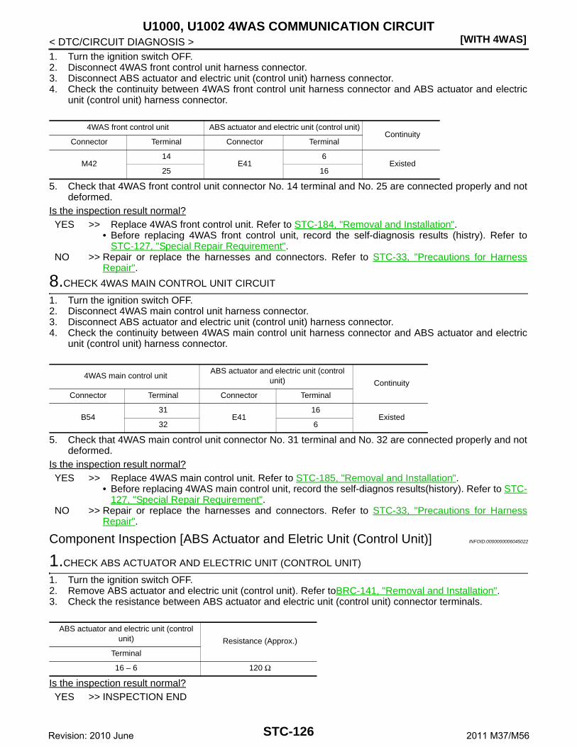
[WITH 4WAS]U1000, U1002 4WAS COMMUNICATION CIRCUIT
< DTC/CIRCUIT DIAGNOSIS >1. Turn the ignition switch OFF.2. Disconnect 4WAS front control unit harness connector.3. Disconnect ABS actuator and electric unit (control unit) harness connector.4. Check the continuity between 4WAS front control unit harness connector and ABS actuator and electric
unit (control unit) harness connector.
5. Check that 4WAS front control unit connector No. 14 terminal and No. 25 are connected properly and notdeformed.
Is the inspection result normal?YES >> Replace 4WAS front control unit. Refer to STC-184, "Removal and Installation".
• Before replacing 4WAS front control unit, record the self-diagnosis results (histry). Refer toSTC-127, "Special Repair Requirement".
NO >> Repair or replace the harnesses and connectors. Refer to STC-33, "Precautions for HarnessRepair".
8.CHECK 4WAS MAIN CONTROL UNIT CIRCUIT
1. Turn the ignition switch OFF.2. Disconnect 4WAS main control unit harness connector.3. Disconnect ABS actuator and electric unit (control unit) harness connector.4. Check the continuity between 4WAS main control unit harness connector and ABS actuator and electric
unit (control unit) harness connector.
5. Check that 4WAS main control unit connector No. 31 terminal and No. 32 are connected properly and notdeformed.
Is the inspection result normal?YES >> Replace 4WAS main control unit. Refer to STC-185, "Removal and Installation".
• Before replacing 4WAS main control unit, record the self-diagnos results(history). Refer to STC-127, "Special Repair Requirement".
NO >> Repair or replace the harnesses and connectors. Refer to STC-33, "Precautions for HarnessRepair".
Component Inspection [ABS Actuator and Eletric Unit (Control Unit)] INFOID:0000000006045022
1.CHECK ABS ACTUATOR AND ELECTRIC UNIT (CONTROL UNIT)
1. Turn the ignition switch OFF.2. Remove ABS actuator and electric unit (control unit). Refer toBRC-141, "Removal and Installation".3. Check the resistance between ABS actuator and electric unit (control unit) connector terminals.
Is the inspection result normal?YES >> INSPECTION END
4WAS front control unit ABS actuator and electric unit (control unit)Continuity
Connector Terminal Connector Terminal
M4214
E416
Existed25 16
4WAS main control unitABS actuator and electric unit (control
unit) Continuity
Connector Terminal Connector Terminal
B5431
E4116
Existed32 6
ABS actuator and electric unit (control unit) Resistance (Approx.)
Terminal
16 – 6 120 Ω
STC-126Revision: 2010 June 2011 M37/M56

U1000, U1002 4WAS COMMUNICATION CIRCUIT[WITH 4WAS]
C
D
E
F
H
I
J
K
L
M
A
B
TC
N
O
P
< DTC/CIRCUIT DIAGNOSIS >
S
NO >> Replace ABS actuator and electric unit (control unit). Refer toBRC-141, "Removal and Installa-tion".
Component Inspection (Yaw Rate/Side/Decel G Sensor) INFOID:0000000006045023
1.CHECK YAW RATE/SIDE/DECEL G SENSOR
1. Turn the ignition switch OFF.2. Remove yaw rate/side/decel G sensor. Refer to BRC-143, "Removal and Installation".3. Check the resistance between yaw rate/side/decel G sensor connector terminals.
Is the inspection result normal?YES >> INSPECTION ENDNO >> Replace yaw rate/side/decel G sensor. Refer to BRC-143, "Removal and Installation".
Special Repair Requirement INFOID:0000000006136391
Before replacing 4WAS front control unit, record the self-diagnosis results (history).CAUTION:• Never erase the memory (history) of self-diagnosis results when replacing 4WAS front control unit
after diagnosis.• Erase the memory of the self-diagnosis results (record) after printing out or recording all the values
of “DATA MONITOR”.
Yaw rate/side/decel G sensorResistance (Approx.)
Terminal
2 – 3 120 Ω
STC-127Revision: 2010 June 2011 M37/M56

[WITH 4WAS]U1010 4WAS COMMUNICATION CIRCUIT
< DTC/CIRCUIT DIAGNOSIS >
U1010 4WAS COMMUNICATION CIRCUIT
Description INFOID:0000000006045025
• 4WAS front control unit and 4WAS main control unit transmit/receive information to/from each other for opti-mum control of the 4WAS system with the specified 4WAS system line (4WAS communication line) between4WAS front control unit and 4WAS main control unit.
• Be careful to repair wirings because 4WAS system specified line adopts twisted-pair wires. Refer to STC-33,"Precautions for Harness Repair".
DTC Logic INFOID:0000000006045026
DTC DETECTION LOGIC
DTC CONFIRMATION PROCEDURE
1.RECHECK DTC
With CONSULT-III1. Turn the ignition switch from OFF to ON.2. Perform self-diagnosis for “4WAS(FRONT)”.Is DTC “U1010” detected?YES >> Proceed to diagnosis procedure. Refer to STC-128, "Diagnosis Procedure".NO >> INSPECTION END
Diagnosis Procedure INFOID:0000000006045027
1.4WAS FRONT CONTROL UNIT
Check that there is no malfunction in 4WAS front control unit harness connector or disconnection.Is the inspection result normal? YES >> Replace 4WAS front control unit. Refer to STC-184, "Removal and Installation".
• Before replacing 4WAS front control unit, record the self-diagnosis results (histry). Refer toSTC-128, "Special Repair Requirement".
NO >> Repair or replace the harnesses and connectors. Refer to STC-33, "Precautions for HarnessRepair".
Special Repair Requirement INFOID:0000000006136392
Before replacing 4WAS front control unit, record the self-diagnosis results (history).CAUTION:• Never erase the memory (history) of self-diagnosis results when replacing 4WAS front control unit
after diagnosis.• Erase the memory of the self-diagnosis results (record) after printing out or recording all the values
of “DATA MONITOR”.
DTC Display Item Malfunction detected condition Possible cause
U1010 CONTROL UNIT(CAN)When detecting error during the initial diagnosis of 4WAS controller of 4WAS front control unit
4WAS front control unit error
STC-128Revision: 2010 June 2011 M37/M56

C1900, C1901, C1906, C1907, C1927, C1933 4WAS MAIN CONTROL UNIT[WITH 4WAS]
C
D
E
F
H
I
J
K
L
M
A
B
TC
N
O
P
< DTC/CIRCUIT DIAGNOSIS >
S
C1900, C1901, C1906, C1907, C1927, C1933 4WAS MAIN CONTROL UNIT
DTC Logic INFOID:0000000006045029
DTC DETECTION LOGIC
DTC CONFIRMATION PROCEDURE
1.RECHECK DTC
With CONSULT-III1. Turn the ignition switch from OFF to ON.2. Perform self-diagnosis for “4WAS(MAIN)/RAS/HICAS”.Is DTC “C1900”, “C1901”, “C1906”, “C1907”, “C1927” or “C1933” detected?YES >> Proceed to diagnosis procedure. Refer to STC-129, "Diagnosis Procedure".NO >> INSPECTION END
Diagnosis Procedure INFOID:0000000006045030
1.PERFORM SELF-DIAGNOSIS (4WAS MAIN CONTROL UNIT)
With CONSULT-IIIPerform self-diagnosis for “4WAS(MAIN)/RAS/HICAS”.Is any DTC “C1900”, “C1901”, “C1906”, “C1907”, “C1927” or “C1933” detected?YES >> Replace 4WAS main control unit. Refer to STC-185, "Removal and Installation".
• Before replacing 4WAS main control unit, record the self-diagnos results(history). Refer to STC-129, "Special Repair Requirement".
NO >> GO TO 2.
2.CHECK INFORMATION
With CONSULT-IIICheck the “DATA MONITOR” value of each DTC detected with the self-diagnosis function. Refer to STC-63,"Reference Value".Is each data the standard value?YES >> Check each harness connector pin terminal for disconnection.NO >> Replace 4WAS main control unit. Refer to STC-185, "Removal and Installation".
• Before replacing 4WAS main control unit, record the self-diagnos results(history). Refer to STC-129, "Special Repair Requirement".
Special Repair Requirement INFOID:0000000006136324
Before replacing 4WAS main control unit, record the self-diagnosis results (history).CAUTION:
DTC Display Item Malfunction detected condition Possible cause
C1900CONTROL UNIT[ABNORMAL1]
An error is detected inside 4WAS main control unit.4WAS main control unit error
C1901CONTROL UNIT[ABNORMAL2]
An error is detected inside 4WAS main control unit.4WAS main control unit error
C1906CONTROL UNIT[ABNORMAL5]
An error is detected inside 4WAS main control unit.4WAS main control unit error
C1907CONTROL UNIT[ABNORMAL4]
An error is detected inside 4WAS main control unit.4WAS main control unit error
C1927CONTROL UNIT[ABNORMAL5]
An error is detected inside 4WAS main control unit.4WAS main control unit error
C1933 CONTROL UNIT An error is detected inside 4WAS main control unit.4WAS main control unit error
STC-129Revision: 2010 June 2011 M37/M56

[WITH 4WAS]C1900, C1901, C1906, C1907, C1927, C1933 4WAS MAIN CONTROL UNIT
< DTC/CIRCUIT DIAGNOSIS >• Never erase the memory (history) of self-diagnosis results when replacing 4WAS main control unit
after diagnosis.• Erase the memory of the self-diagnosis results (record) after printing out or recording all the values
of “DATA MONITOR”.
STC-130Revision: 2010 June 2011 M37/M56

C1902, C1903, C1904, C1910, C1913 4WAS REAR MOTOR OUTPUT[WITH 4WAS]
C
D
E
F
H
I
J
K
L
M
A
B
TC
N
O
P
< DTC/CIRCUIT DIAGNOSIS >
S
C1902, C1903, C1904, C1910, C1913 4WAS REAR MOTOR OUTPUT
Description INFOID:0000000006045032
• 4WAS rear motor activates 4WAS rear actuator.• Maintain the toe-stiffness of rear wheels against the road external force because the irreversible sufficiency
performance hypoid gear is used.
DTC Logic INFOID:0000000006045033
DTC DETECTION LOGIC
DTC CONFIRMATION PROCEDURE
1.RECHECK DTC
With CONSULT-III1. Perform “SELF DIAGNOSTIC MODE” item on “ACTIVE TEST” for “4WAS(MAIN)/RAS/HICAS”.
CAUTION:Perform the active test while stopping the vehicle.
2. Perform self-diagnosis for “4WAS(MAIN)/RAS/HICAS”.Is DTC “C1902”, “C1903”, “C1904”, “C1910” or “C1913” detected?YES >> Proceed to diagnosis procedure. Refer to STC-131, "Diagnosis Procedure".NO >> INSPECTION END
Diagnosis Procedure INFOID:0000000006045034
1.CHECK 4WAS REAR MOTOR CIRCUIT
1. Turn the ignition switch OFF.2. Disconnect 4WAS main control unit harness connector.3. Disconnect 4WAS rear motor harness connector.4. Check the continuity between 4WAS main control unit harness connector and 4WAS rear motor harness
connector.
Is the inspection result normal?
DTC Display Item Malfunction detected condition Possible cause
C1902MOTOR OUTPUT[REV CURRENT]
4WAS rear motor current error is detected.(4WAS rear motor current output direction differs.)
4WAS rear motor error
C1903MOTOR OUTPUT[NO CURRENT]
4WAS rear motor current error is detected.(Current is input to 4WAS main control unit if 4WAS main control unit output is “OFF”.)
4WAS rear motor error
C1904MOTOR OUTPUT[OVERCURRENT]
4WAS rear motor current error is detected.(4WAS rear motor output is overcurrent.)
4WAS rear motor error
C1910MOTOR OUTPUT[MOTOR LOCK]
4WAS rear motor inside error is detected.(4WAS rear motor does not move or the rear wheel an-gle sensor does not change if 4WAS main control unit output is 14 A or more.)
4WAS rear motor error
C1913MOTOR OUTPUT[ABNORML SIG]
4WAS rear motor current error is detected.(4WAS rear motor does not move or the rear wheel an-gle sensor output does not change when 4WAS main control unit output is 18 A or more, and 4WAS main mo-tor output is low.)
4WAS rear motor error
4WAS main control unit 4WAS rear motorContinuity
Connector Terminal Connector Terminal
B5438
B361
Existed39 2
STC-131Revision: 2010 June 2011 M37/M56

[WITH 4WAS]C1902, C1903, C1904, C1910, C1913 4WAS REAR MOTOR OUTPUT
< DTC/CIRCUIT DIAGNOSIS >YES >> GO TO 2.NO >> Repair or replace the harnesses and connectors.
2.CHECK 4WAS REAR MOTOR
Check the continuity between 4WAS rear motor connector terminals. Refer to STC-132, "Component Inspec-tion (4WAS Rear Motor)".Is the inspection result normal?YES >> GO TO 3.NO >> Replace 4WAS rear actuator. Refer to STC-187, "Removal and Installation".
3.PERFORM ACTIVE TEST (4WAS MAIN CONTROL UNIT)
With CONSULT-III1. Connect 4WAS main control unit harness connector.2. Connect 4WAS rear motor harness connector.3. Perform “SELF DIAGNOSTIC MODE” item on “ACTIVE TEST” for “4WAS(MAIN)/RAS/HICAS”.
CAUTION:Perform the active test while vehicle is stopped.
4. Check “MOTOR VOLTAGE”, “MOTOR CURRENT” and “MTR CRNT OPE” while performing the activetest.
Is “MONITOR” the standard value?YES >> GO TO 4.NO >> Replace 4WAS rear actuator. Refer to STC-187, "Removal and Installation".
4.PERFORM SELF-DIAGNOSIS (4WAS MAIN CONTROL UNIT)
With CONSULT-IIIPerform self-diagnosis for “4WAS(MAIN)/RAS/HICAS”.Is any DTC “C1902”, “C1903”, “C1904”, “C1910” or “C1913” detected?YES >> Replace 4WAS main control unit. Refer to STC-185, "Removal and Installation".
• Before replacing 4WAS main control unit, record the self-diagnos results(history). Refer to STC-133, "Special Repair Requirement".
NO >> GO TO 5.
5.CHECK INFORMATION
With CONSULT-IIICheck the “DATA MONITOR” value of each DTC detected with the self-diagnosis function. Refer to STC-63,"Reference Value".Is each data the standard value?YES >> Check each harness connector pin terminal for disconnection.NO >> Replace 4WAS main control unit. Refer to STC-185, "Removal and Installation".
• Before replacing 4WAS main control unit, record the self-diagnos results(history). Refer to STC-133, "Special Repair Requirement".
Component Inspection (4WAS Rear Motor) INFOID:0000000006045035
1.CHECK 4WAS REAR MOTOR
1. Turn the ignition switch OFF.2. Disconnect 4WAS rear motor harness connector.3. Check the continuity between 4WAS rear motor connector terminals.
Monitor item Condition Display value
MOTOR VOLTAGE Ignition switch: ON Battery voltage
MOTOR CURRENT 4WAS rear motor running 0 – 20 A
MTR CRNT OPE
4WAS rear actuator neutral condition and vehicle straight-ahead position
Approx. (−2) – (+2) A
4WAS rear motor running Approx. −20) – (+20) A
STC-132Revision: 2010 June 2011 M37/M56

C1902, C1903, C1904, C1910, C1913 4WAS REAR MOTOR OUTPUT[WITH 4WAS]
C
D
E
F
H
I
J
K
L
M
A
B
TC
N
O
P
< DTC/CIRCUIT DIAGNOSIS >
S
Is the inspection result normal?YES >> INSPECTION ENDNO >> Replace 4WAS rear actuator. Refer to STC-187, "Removal and Installation".
Special Repair Requirement INFOID:0000000006136393
Before replacing 4WAS main control unit, record the self-diagnosis results (history).CAUTION:• Never erase the memory (history) of self-diagnosis results when replacing 4WAS main control unit
after diagnosis.• Erase the memory of the self-diagnosis results (record) after printing out or recording all the values
of “DATA MONITOR”.
4WAS rear motorContinuity
Terminal
1 – 2 Existed
STC-133Revision: 2010 June 2011 M37/M56

[WITH 4WAS]C1905, C1908, C1922, C1925, C1928 4WAS MAIN CONTROL UNIT
< DTC/CIRCUIT DIAGNOSIS >
C1905, C1908, C1922, C1925, C1928 4WAS MAIN CONTROL UNIT
DTC Logic INFOID:0000000006045037
DTC DETECTION LOGIC
DTC CONFIRMATION PROCEDURE
1.RECHECK DTC
With CONSULT-III1. Turn the ignition switch from OFF to ON.2. Perform self-diagnosis for “4WAS(MAIN)/RAS/HICAS”.Is any DTC “C1905”, “C1908”, “C1922”, “C1925” or “C1928” detected?YES >> Proceed to diagnosis procedure. Refer to STC-134, "Diagnosis Procedure".NO >> INSPECTION END
Diagnosis Procedure INFOID:0000000006045038
1.PERFORM SELF-DIAGNOSIS (4WAS MAIN CONTROL UNIT)
With CONSULT-IIIPerform self-diagnosis for “4WAS(MAIN)/RAS/HICAS”.Is any DTC “C1905”, “C1908”, “C1922”, “C1925” or “C1928” detected?YES >> Replace 4WAS main control unit. Refer to STC-185, "Removal and Installation".
• Before replacing 4WAS main control unit, record the self-diagnos results(history). Refer to STC-134, "Special Repair Requirement".
NO >> GO TO 2.
2.CHECK INFORMATION
With CONSULT-IIICheck the “DATA MONITOR” value of each DTC detected with the self-diagnosis function. Refer to STC-63,"Reference Value".Is each data the standard value?YES >> Check each harness connector pin terminal for disconnection.NO >> Replace 4WAS main control unit. Refer to STC-185, "Removal and Installation".
• Before replacing 4WAS main control unit, record the self-diagnos results(history). Refer to STC-134, "Special Repair Requirement".
Special Repair Requirement INFOID:0000000006136394
Before replacing 4WAS main control unit, record the self-diagnosis results (history).CAUTION:• Never erase the memory (history) of self-diagnosis results when replacing 4WAS main control unit
after diagnosis.
DTC Display Item Malfunction detected condition Possible cause
C1905CONTROL UNIT[ABNORMAL3]
An error is detected inside 4WAS main control unit.4WAS main control unit error
C1908CONTROL UNIT[ABNORMAL7]
An error is detected inside 4WAS main control unit.4WAS main control unit error
C1922CONTROL UNIT[ABNORMAL8]
An error is detected inside 4WAS main control unit.4WAS main control unit error
C1925 AD CONVERTER An error is detected inside 4WAS main control unit.4WAS main control unit error
C1928CONTROL UNIT[ABNORMAL9]
An error is detected inside 4WAS main control unit.4WAS main control unit error
STC-134Revision: 2010 June 2011 M37/M56

C1905, C1908, C1922, C1925, C1928 4WAS MAIN CONTROL UNIT[WITH 4WAS]
C
D
E
F
H
I
J
K
L
M
A
B
TC
N
O
P
< DTC/CIRCUIT DIAGNOSIS >
S
• Erase the memory of the self-diagnosis results (record) after printing out or recording all the valuesof “DATA MONITOR”.
STC-135Revision: 2010 June 2011 M37/M56

[WITH 4WAS]C1909 4WAS MAIN CONTROL UNIT
< DTC/CIRCUIT DIAGNOSIS >
C1909 4WAS MAIN CONTROL UNIT
DTC Logic INFOID:0000000006045040
DTC DETECTION LOGIC
DTC CONFIRMATION PROCEDURE
1.RECHECK DTC
With CONSULT-III1. Turn the ignition switch from OFF to ON.2. Perform self-diagnosis for “4WAS(MAIN)/RAS/HICAS”.Is DTC “C1909” detected?YES >> Proceed to diagnosis procedure. Refer to STC-136, "Diagnosis Procedure".NO >> INSPECTION END
Diagnosis Procedure INFOID:0000000006045041
1.CHECK 4WAS MAIN CONTROL UNIT GROUND
1. Turn the ignition switch OFF.2. Disconnect 4WAS main control unit harness connector.3. Check the continuity between 4WAS main control unit harness connector terminal and the ground.
Is the inspection result normal?YES >> GO TO 2.NO >> Repair or replace the harnesses and connectors.
2.CHECK 4WAS MAIN CONTROL UNIT POWER SUPPLY (1)
1. Check the voltage between 4WAS main control unit harness connector terminal and ground.
2. Turn the ignition switch ON.CAUTION:Never start the engine.
3. Check the voltage between 4WAS main control unit harness connector terminal and ground.
Is the inspection result normal?YES >> GO TO 4.NO >> GO TO 3.
DTC Display Item Malfunction detected condition Possible cause
C1909CONTROL UNIT[ABNORMAL6]
An error is detected inside 4WAS main control unit. 4WAS main control unit
4WAS main control unit— Continuity
Connector Terminal
B5434
Ground Existed40
4WAS main control unit— Voltage (Approx.)
Connector Terminal
B54 27 Ground 0 V
4WAS main control unit— Voltage (Approx.)
Connector Terminal
B54 27 Ground Battery voltage
STC-136Revision: 2010 June 2011 M37/M56
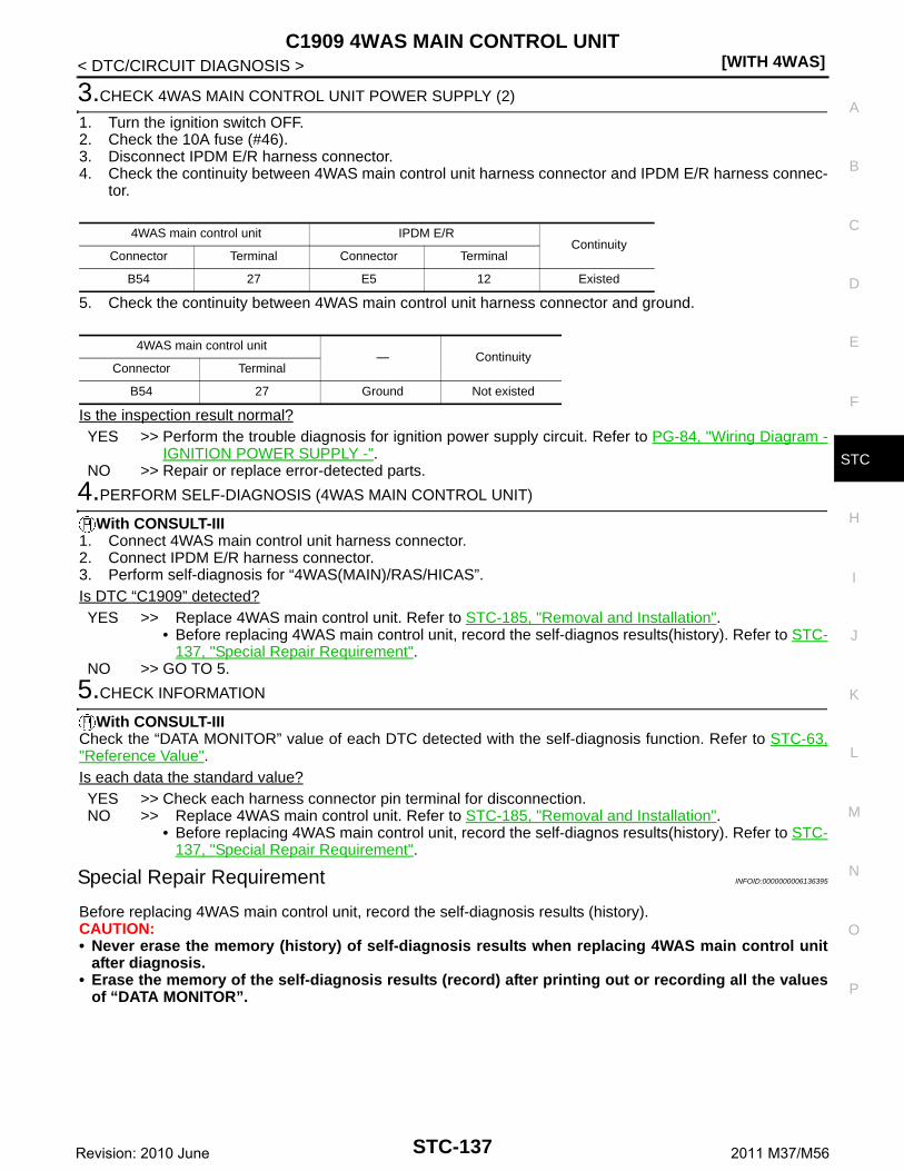
C1909 4WAS MAIN CONTROL UNIT[WITH 4WAS]
C
D
E
F
H
I
J
K
L
M
A
B
TC
N
O
P
< DTC/CIRCUIT DIAGNOSIS >
S
3.CHECK 4WAS MAIN CONTROL UNIT POWER SUPPLY (2)
1. Turn the ignition switch OFF.2. Check the 10A fuse (#46).3. Disconnect IPDM E/R harness connector.4. Check the continuity between 4WAS main control unit harness connector and IPDM E/R harness connec-
tor.
5. Check the continuity between 4WAS main control unit harness connector and ground.
Is the inspection result normal?YES >> Perform the trouble diagnosis for ignition power supply circuit. Refer to PG-84, "Wiring Diagram -
IGNITION POWER SUPPLY -".NO >> Repair or replace error-detected parts.
4.PERFORM SELF-DIAGNOSIS (4WAS MAIN CONTROL UNIT)
With CONSULT-III1. Connect 4WAS main control unit harness connector.2. Connect IPDM E/R harness connector.3. Perform self-diagnosis for “4WAS(MAIN)/RAS/HICAS”.Is DTC “C1909” detected?YES >> Replace 4WAS main control unit. Refer to STC-185, "Removal and Installation".
• Before replacing 4WAS main control unit, record the self-diagnos results(history). Refer to STC-137, "Special Repair Requirement".
NO >> GO TO 5.
5.CHECK INFORMATION
With CONSULT-IIICheck the “DATA MONITOR” value of each DTC detected with the self-diagnosis function. Refer to STC-63,"Reference Value".Is each data the standard value?YES >> Check each harness connector pin terminal for disconnection.NO >> Replace 4WAS main control unit. Refer to STC-185, "Removal and Installation".
• Before replacing 4WAS main control unit, record the self-diagnos results(history). Refer to STC-137, "Special Repair Requirement".
Special Repair Requirement INFOID:0000000006136395
Before replacing 4WAS main control unit, record the self-diagnosis results (history).CAUTION:• Never erase the memory (history) of self-diagnosis results when replacing 4WAS main control unit
after diagnosis.• Erase the memory of the self-diagnosis results (record) after printing out or recording all the values
of “DATA MONITOR”.
4WAS main control unit IPDM E/RContinuity
Connector Terminal Connector Terminal
B54 27 E5 12 Existed
4WAS main control unit— Continuity
Connector Terminal
B54 27 Ground Not existed
STC-137Revision: 2010 June 2011 M37/M56

[WITH 4WAS]C1911, C1912 4WAS REAR MOTOR POWER SUPPLY
< DTC/CIRCUIT DIAGNOSIS >
C1911, C1912 4WAS REAR MOTOR POWER SUPPLY
Description INFOID:0000000006045043
The power supply for 4WAS rear motor.
DTC Logic INFOID:0000000006045044
DTC DETECTION LOGIC
DTC CONFIRMATION PROCEDURE
1.RECHECK DTC
1. Turn the ignition switch from OFF to ON.CAUTION:Never drive the vehicle. Wait 15 minutes or more.
2. Perform self-diagnosis for “4WAS(MAIN)/RAS/HICAS”.Is DTC “C1911” or “C1912” detected?YES >> Proceed to diagnosis procedure. Refer to STC-138, "Diagnosis Procedure".NO >> INSPECTION END
Diagnosis Procedure INFOID:0000000006045045
1.CHECK 4WAS MAIN CONTROL UNIT GROUND
1. Turn the ignition switch OFF.2. Disconnect 4WAS main control unit harness connector.3. Check the continuity between 4WAS main control unit harness connector terminal and the ground.
Is the inspection result normal?YES >> GO TO 2.NO >> Repair or replace the harnesses and connectors.
2.CHECK 4WAS MAIN CONTROL UNIT POWER SUPPLY (1)
1. Check the voltage between 4WAS main control unit harness connector terminal and ground.
2. Turn the ignition switch ON.CAUTION:Never start the engine.
3. Check the voltage between 4WAS main control unit harness connector terminal and ground.
DTC Display Item Malfunction detected condition Possible cause
C1911MOTOR VOLTAGE[LOW VOLTAGE]
4WAS rear motor voltage error is detected.(4WAS rear motor voltage is low.)
4WAS rear motor power supply error
C1912MOTOR VOLTAGE[BAD OBSTRCT]
4WAS rear motor voltage error is detected.(Voltage is applied to 4WAS main motor when 4WAS main control unit output is “OFF”.)
4WAS rear motor power supply error
4WAS main control unit— Continuity
Connector Terminal
B5434
Ground Existed40
4WAS main control unit— Voltage (Approx.)
Connector Terminal
B54 27 Ground 0 V
STC-138Revision: 2010 June 2011 M37/M56

C1911, C1912 4WAS REAR MOTOR POWER SUPPLY[WITH 4WAS]
C
D
E
F
H
I
J
K
L
M
A
B
TC
N
O
P
< DTC/CIRCUIT DIAGNOSIS >
S
Is the inspection result normal?YES >> GO TO 4.NO >> GO TO 3.
3.CHECK 4WAS MAIN CONTROL UNIT POWER SUPPLY (2)
1. Turn the ignition switch OFF.2. Check the 10A fuse (#46).3. Disconnect IPDM E/R harness connector.4. Check the continuity between 4WAS main control unit harness connector and IPDM E/R harness connec-
tor.
5. Check the continuity between 4WAS main control unit harness connector and ground.
Is the inspection result normal?YES >> Perform the trouble diagnosis for ignition power supply circuit. Refer to PG-84, "Wiring Diagram -
IGNITION POWER SUPPLY -".NO >> Repair or replace error-detected parts.
4.CHECK 4WAS REAR MOTOR POWER SUPPLY CIRCUIT (1)
1. Remove 4WAS rear motor relay.2. Check the continuity between 4WAS rear motor relay harness connector and ground.
3. Check the continuity between 4WAS main control unit harness connector and IPDM E/R harness connec-tor.
Is the inspection result normal?YES >> GO TO 5.NO >> Repair or replace error-detected parts.
5.CHECK 4WAS REAR MOTOR POWER SUPPLY CIRCUIT (2)
1. Check 20A fusible link (#37).2. Check the harness for open or short between 4WAS front control unit harness connector No.3 terminal
and 20A fusible link (#37).Is the inspection result normal?YES >> GO TO 6.
4WAS main control unit— Voltage (Approx.)
Connector Terminal
B54 27 Ground Battery voltage
4WAS main control unit IPDM E/RContinuity
Connector Terminal Connector Terminal
B54 27 E5 12 Existed
4WAS main control unit— Continuity
Connector Terminal
B54 27 Ground Not existed
4WAS rear motor relay— Continuity
Connector Terminal
B532
GroundExisted
1 Not existed
4WAS rear motor relay 4WAS main control unitContinuity
Connector Terminal Connector Terminal
B53 1 B54 25 Existed
STC-139Revision: 2010 June 2011 M37/M56

[WITH 4WAS]C1911, C1912 4WAS REAR MOTOR POWER SUPPLY
< DTC/CIRCUIT DIAGNOSIS >NO >> Repair or replace error-detected parts.
6.CHECK 4WAS REAR MOTOR POWER SUPPLY CIRCUIT (3)
1. Turn the ignition switch ON.CAUTION:Never start the engine.
2. Check the voltage between 4WAS main control unit harness connectors and the ground.
3. Turn the ignition switch OFF.Is the inspection result normal?YES >> GO TO 7.NO >> Replace 4WAS main control unit. Refer to STC-185, "Removal and Installation".
• Before replacing 4WAS main control unit, record the self-diagnos results(history). Refer to STC-141, "Special Repair Requirement".
7.CHECK 4WAS REAR MOTOR RELAY
Check 4WAS rear motor relay. Refer to STC-141, "Component Inspection".Is the inspection result normal?YES >> GO TO 8.NO >> Replace 4WAS rear motor relay.
8.CHECK 4WAS REAR MOTOR POWER SUPPLY
1. Connect 4WAS main control unit harness connector.2. Install 4WAS rear motor relay.3. Turn the ignition switch ON.
CAUTION:Never start the engine.
4. Check the voltage between 4WAS main control unit harness connectors and the ground.
Is the inspection result normal?YES >> GO TO 9.NO >> Replace 4WAS main control unit. Refer to STC-185, "Removal and Installation".
• Before replacing 4WAS main control unit, record the self-diagnos results(history). Refer to STC-141, "Special Repair Requirement".
9.PERFORM SELF-DIAGNOSIS (4WAS MAIN CONTROL UNIT)
With CONSULT-IIIPerform self-diagnosis for “4WAS(MAIN)/RAS/HICAS”.Is DTC “C1911” or “C1912” detected?YES >> Replace 4WAS main control unit. Refer to STC-185, "Removal and Installation".
• Before replacing 4WAS main control unit, record the self-diagnos results(history). Refer to STC-141, "Special Repair Requirement".
NO >> GO TO 10.
10.CHECK INFORMATION
With CONSULT-IIICheck the “DATA MONITOR” value of each DTC detected with the self-diagnosis function. Refer to STC-63,"Reference Value".Is each data the standard value?
4WAS main control unit— Voltage (Approx.)
Connector Terminal
B54 25 Ground Battery voltage
4WAS main control unit— Voltage (Approx.)
Connector Terminal
B54 37 Ground Battery voltage
STC-140Revision: 2010 June 2011 M37/M56

C1911, C1912 4WAS REAR MOTOR POWER SUPPLY[WITH 4WAS]
C
D
E
F
H
I
J
K
L
M
A
B
TC
N
O
P
< DTC/CIRCUIT DIAGNOSIS >
S
YES >> Check each harness connector pin terminal for disconnection.NO >> Replace 4WAS main control unit. Refer to STC-185, "Removal and Installation".
• Before replacing 4WAS main control unit, record the self-diagnos results(history). Refer to STC-141, "Special Repair Requirement".
Component Inspection INFOID:0000000006045046
1.CHECK 4WAS REAR MOTOR RELAY
1. Turn the ignition switch OFF.2. Remove 4WAS rear motor relay connector.3. Apply 12 V to 4WAS rear motor relay connector No. 1 terminal and No. 2 terminal.
CAUTION:• Never make the terminals short.• Connect the fuse between the terminals when applying the voltage.
4. Check the continuity between 4WAS rear motor relay connector terminals.
5. Check the resistance between 4WAS rear motor relay connector terminals.
Is the inspection result normal?YES >> INSPECTION ENDNO >> Replace 4WAS rear motor relay.
Special Repair Requirement INFOID:0000000006136396
Before replacing 4WAS main control unit, record the self-diagnosis results (history).CAUTION:• Never erase the memory (history) of self-diagnosis results when replacing 4WAS main control unit
after diagnosis.• Erase the memory of the self-diagnosis results (record) after printing out or recording all the values
of “DATA MONITOR”.
4WAS rear motor relayContinuity
Terminal Condition
3 – 5
Apply the voltage between No. 1 ter-minal and No. 2 terminal.
Existed
Do not apply the voltage between No. 1 terminal and No. 2 terminal.
Not existed
4WAS rear motor relay Resistance (Ap-prox.)Terminal
1 2 50 Ω
STC-141Revision: 2010 June 2011 M37/M56

[WITH 4WAS]C1914 REAR WHEEL STEERING ANGLE SENSOR
< DTC/CIRCUIT DIAGNOSIS >
C1914 REAR WHEEL STEERING ANGLE SENSOR
DTC Logic INFOID:0000000006045048
DTC DETECTION LOGIC
DTC CONFIRMATION PROCEDURE
1.RECHECK DTC
With CONSULT-III1. Turn the ignition switch from OFF to ON.2. Perform self-diagnosis for “4WAS(MAIN)/RAS/HICAS”.Is DTC “C1914” detected?YES >> Proceed to diagnosis procedure. Refer to STC-142, "Diagnosis Procedure".NO >> INSPECTION END
Diagnosis Procedure INFOID:0000000006045049
1.CHECK REAR WHEEL STEERING ANGLE SENSOR POWER SUPPLY
1. Turn the ignition switch OFF.2. Check the voltage between 4WAS main control unit harness connector terminal and the ground.
3. Turn the ignition switch ON.CAUTION:Never start the engine.
4. Check the voltage between 4WAS main control unit harness connector terminal and the ground.
Is the inspection result normal?YES >> GO TO 2.NO >> Replace 4WAS main control unit. Refer to STC-185, "Removal and Installation".
• Before replacing 4WAS main control unit, record the self-diagnos results(history). Refer to STC-143, "Special Repair Requirement".
2.CHECK REAR WHEEL STEERING ANGLE SENSOR
Check the resistance between the rear wheel steering angle sensor connector terminals. Refer to STC-143,"Component Inspection".Is the inspection result normal?YES >> GO TO 3.NO >> Replace 4WAS rear actuator. Refer to STC-187, "Removal and Installation".
3.CHECK REAR WHEEL STEERING ANGLE SENSOR POWER SUPPLY CIRCUIT
1. Disconnect 4WAS main control unit harness connector.2. Check the continuity between 4WAS main control unit harness connector terminal and the rear wheel
steering angle sensor harness connector terminal.
DTC Display Item Malfunction detected condition Possible cause
C1914RR ST ANGLE SENSOR[ABNORML VOL]
The rear wheel angle sensor power supply error is de-tected.
Rear wheel steering sen-sor power supply error
4WAS main control unit— Value (Approx.)
Connector Terminal
B54 5 Ground 0 V
4WAS main control unit— Value (Approx.)
Connector Terminal
B54 5 Ground 5 V
STC-142Revision: 2010 June 2011 M37/M56

C1914 REAR WHEEL STEERING ANGLE SENSOR[WITH 4WAS]
C
D
E
F
H
I
J
K
L
M
A
B
TC
N
O
P
< DTC/CIRCUIT DIAGNOSIS >
S
Is the inspection result normal?YES >> GO TO 4.NO >> Repair or replace the harnesses and connectors.
4.PERFORM SELF-DIAGNOSIS (4WAS MAIN CONTROL UNIT)
With CONSULT-III1. Connect 4WAS main control unit harness connector.2. Connect the rear wheel steering angle sensor harness connector.3. Perform self-diagnosis for “4WAS(MAIN)/RAS/HICAS”.Is DTC “C1914” detected?YES >> Replace 4WAS main control unit. Refer to STC-185, "Removal and Installation".
• Before replacing 4WAS main control unit, record the self-diagnos results(history). Refer to STC-143, "Special Repair Requirement".
NO >> GO TO 5.
5.CHECK INFORMATION
With CONSULT-IIICheck the “DATA MONITOR” value of each DTC detected with the self-diagnosis function. Refer to STC-63,"Reference Value".Is each data the standard value?YES >> Check each harness connector pin terminal for disconnection.NO >> Replace 4WAS main control unit. Refer to STC-185, "Removal and Installation".
• Before replacing 4WAS main control unit, record the self-diagnos results(history). Refer to STC-143, "Special Repair Requirement".
Component Inspection INFOID:0000000006045050
1.CHECK REAR WHEEL STEERING ANGLE SENSOR
1. Turn the ignition switch OFF.2. Disconnect rear wheel steering angle sensor harness connector.3. Check the resistance between rear wheel steering angle sensor connector terminals.
Is the inspection result normal?YES >> INSPECTION ENDNO >> Replace 4WAS rear actuator. Refer to STC-187, "Removal and Installation".
Special Repair Requirement INFOID:0000000006136399
Before replacing 4WAS main control unit, record the self-diagnosis results (history).CAUTION:• Never erase the memory (history) of self-diagnosis results when replacing 4WAS main control unit
after diagnosis.
4WAS main control unit Rear wheel steering angle sensorContinuity
Connector Terminal Connector Terminal
B54 5 B38 1 Existed
B54 5 B38 4 Not existed
B54 15 B38 4 Existed
B54 15 B38 1 Not existed
Rear wheel steering angle sensorResistance (Approx.)
Terminal
1 – 4 1 kΩ
1 – 2 1.2 – 1.5 kΩ
1 – 3 1.2 – 1.5 kΩ
STC-143Revision: 2010 June 2011 M37/M56

[WITH 4WAS]C1914 REAR WHEEL STEERING ANGLE SENSOR
< DTC/CIRCUIT DIAGNOSIS >• Erase the memory of the self-diagnosis results (record) after printing out or recording all the values
of “DATA MONITOR”.
STC-144Revision: 2010 June 2011 M37/M56

C1915, C1916 REAR WHEEL STEERING ANGLE SENSOR[WITH 4WAS]
C
D
E
F
H
I
J
K
L
M
A
B
TC
N
O
P
< DTC/CIRCUIT DIAGNOSIS >
S
C1915, C1916 REAR WHEEL STEERING ANGLE SENSOR
DTC Logic INFOID:0000000006045052
DTC DETECTION LOGIC
DTC CONFIRMATION PROCEDURE
1.RECHECK DTC
With CONSULT-III1. Turn the ignition switch from OFF to ON.2. Perform self-diagnosis for “4WAS(MAIN)/RAS/HICAS”.Is DTC “C1915” or “C1916” detected?YES >> Proceed to diagnosis procedure. Refer to STC-145, "Diagnosis Procedure".NO >> INSPECTION END
Diagnosis Procedure INFOID:0000000006045053
1.CHECK 4WAS REAR ACTUATOR
1. Turn the ignition switch OFF.2. Measure “A” and “B” of 4WAS rear actuator as shown in the fig-
ure.CAUTION:Measure it on the level ground or in the condition that leftand right wheel are lifted up.
Is the differential of “A” and “B” 5.4 mm (0.213 in) or less?YES >> GO TO 2.NO >> Replace 4WAS rear actuator. Refer to STC-187,
"Removal and Installation".
2.CHECK REAR WHEEL STEERING ANGLE SENSOR (1)
With CONSULT-III1. Start engine.
CAUTION:Check condition with the vehicle stopped.
2. Check DATA MONITOR “RR ST ANG-MAI” and “RR ST ANG-SUB” value of 4WAS main control unit.
Is the inspection result normal?YES >> GO TO 3.NO >> Replace 4WAS rear actuator. Refer to STC-187, "Removal and Installation".
3.CHECK REAR WHEEL STEERING ANGLE SENSOR (2)
Check the voltage between 4WAS main control unit harness connector terminal and ground.
DTC Display Item Malfunction detected condition Possible cause
C1915RR ST ANGLE SENSOR[MAIN SIGNAL]
The rear wheel angle sensor signal (main) error is de-tected.
Rear wheel steering sen-sor output voltage error
C1916RR ST ANGLE SENSOR[SUB SIGNAL]
If the rear wheel angle sensor signal (sub) error is de-tected.
Rear wheel steering sen-sor output voltage error
JPGIB0002ZZ
Monitored item Condition Display value
RR ST ANG-MAI Straight-ahead Approx. 2.4 V
RR ST ANG-SUB Straight-ahead Approx. 2.6 V
STC-145Revision: 2010 June 2011 M37/M56

[WITH 4WAS]C1915, C1916 REAR WHEEL STEERING ANGLE SENSOR
< DTC/CIRCUIT DIAGNOSIS >
Is the differential between terminal voltage No. 4 and No.7 approximately 1 V or more?YES >> Replace 4WAS main control unit. Refer to STC-185, "Removal and Installation".
• Before replacing 4WAS main control unit, record the self-diagnos results(history). Refer to STC-147, "Special Repair Requirement".
NO >> GO TO 4.
4.CHECK REAR WHEEL STEERING ANGLE SENSOR (3)
Check the resistance between rear wheel steering angle sensor connector terminals. Refer to STC-147,"Component Inspection".Is the inspection result normal?YES >> GO TO 5.NO >> Replace 4WAS rear actuator. Refer to STC-187, "Removal and Installation".
5.CHECK REAR WHEEL STEERING ANGLE SENSOR POWER SUPPLY CIRCUIT
1. Disconnect 4WAS main control unit harness connector.2. Check for continuity between 4WAS main control unit harness connector terminal and rear wheel steering
angle sensor harness connector terminal.
Is the inspection result normal?YES >> GO TO 6.NO >> Repair or replace each harness and connector.
6.PERFORM SELF-DIAGNOSIS (4WAS MAIN CONTROL UNIT)
With CONSULT-III1. Connect 4WAS main control unit harness connector.2. Connect rear wheel steering angle sensor harness connector.3. Perform 4WAS main control unit self-diagnosis.Is DTC “C1915” or “C1916” detected?YES >> Replace 4WAS main control unit. Refer to STC-185, "Removal and Installation".
• Before replacing 4WAS main control unit, record the self-diagnos results(history). Refer to STC-147, "Special Repair Requirement".
NO >> GO TO 7.
7.CHECK INFORMATION
With CONSULT-IIICheck the “DATA MONITOR” value of each DTC detected with the self-diagnosis function. Refer to STC-63,"Reference Value".Is each data standard?
4WAS main control unit— Voltage (Approx.)
Connector Terminal
B544
Ground2.4 V
7 2.6 V
4WAS main control unit Rear wheel steering angle sensorContinuity
Connector Terminal Connector Terminal
B54
4
B38
1, 2, 4 Not existed
4 3 Existed
7 1, 3, 4 Not existed
7 2 Existed
5 1 Existed
5 2, 3, 4 Not existed
15 1, 2, 3 Not existed
15 4 Existed
STC-146Revision: 2010 June 2011 M37/M56

C1915, C1916 REAR WHEEL STEERING ANGLE SENSOR[WITH 4WAS]
C
D
E
F
H
I
J
K
L
M
A
B
TC
N
O
P
< DTC/CIRCUIT DIAGNOSIS >
S
YES >> Check pin terminal and connection of each harness connector for non-standard conditions.NO >> Replace 4WAS main control unit. Refer to STC-185, "Removal and Installation".
• Before replacing 4WAS main control unit, record the self-diagnos results(history). Refer to STC-147, "Special Repair Requirement".
Component Inspection INFOID:0000000006045054
1.CHECK REAR WHEEL STEERING ANGLE SENSOR
1. Turn the ignition switch OFF.2. Disconnect rear wheel steering angle sensor harness connector.3. Check the resistance between rear wheel steering angle sensor connector terminals.
Is the inspection result normal?YES >> INSPECTION ENDNO >> Replace 4WAS rear actuator. Refer to STC-187, "Removal and Installation".
Special Repair Requirement INFOID:0000000006136400
Before replacing 4WAS main control unit, record the self-diagnosis results (history).CAUTION:• Never erase the memory (history) of self-diagnosis results when replacing 4WAS main control unit
after diagnosis.• Erase the memory of the self-diagnosis results (record) after printing out or recording all the values
of “DATA MONITOR”.
Rear wheel steering angle sensorResistance (Approx.)
Terminal
1 – 4 1 kΩ
1 – 2 1.2 – 1.5 kΩ
1 – 3 1.2 – 1.5 kΩ
STC-147Revision: 2010 June 2011 M37/M56

[WITH 4WAS]C1917, C1918 REAR WHEEL STEERING ANGLE SENSOR
< DTC/CIRCUIT DIAGNOSIS >
C1917, C1918 REAR WHEEL STEERING ANGLE SENSOR
DTC Logic INFOID:0000000006045056
DTC DETECTION LOGIC
DTC CONFIRMATION PROCEDURE
1.RECHECK DTC
With CONSULT-III1. Start the engine.
CAUTION:Never drive the vehicle.
2. Select “SELF DIAGNOSTIC MODE” item on “ACTIVE TEST” for “4WAS(MAIN)/RAS/HICAS”.3. Perform self-diagnosis for “4WAS(MAIN)/RAS/HICAS”.Is DTC “C1917” or “C1918” detected?YES >> Proceed to diagnosis procedure. Refer to STC-148, "Diagnosis Procedure".NO >> INSPECTION END
Diagnosis Procedure INFOID:0000000006045057
1.CHECK REAR WHEEL STEERING ANGLE SENSOR (1)
With CONSULT-III1. Start engine.
CAUTION:Check the condition with the vehicle stopped.
2. Check “RR ST ANG-MAI” and “RR ST ANG-SUB” item on “DATA MONITOR” for “4WAS(MAIN)/RAS/HICAS”.
Is the inspection result normal?YES >> GO TO 2.NO >> Replace 4WAS rear actuator. Refer to STC-187, "Removal and Installation".
2.CHECK REAR WHEEL STEERING ANGLE SENSOR (2)
Check the voltage between 4WAS main control unit harness connector terminal and ground.
Is the differential between terminal voltage No. 4 and No.7 approximately 1 V or more?YES >> Replace 4WAS main control unit. Refer to STC-185, "Removal and Installation".
DTC Display Item Malfunction detected condition Possible cause
C1917RR ST ANGLE SENSOR[OFFSET SIG1]
The rear wheel angle sensor signal (main and sub) er-ror is detected.(The output signal value differs temporarily between main and sub.)
Rear wheel steering sen-sor (main and sub) output signal value error signal
C1918RR ST ANGLE SENSOR[OFFSET SIG2]
The rear wheel angle sensor signal (main and sub) er-ror is detected.(The output signal value differs between main and sub.)
Rear wheel steering sen-sor (main and sub) output signal error
Monitored item Condition Display value
RR ST ANG-MAI Straight-ahead Approx. 2.4 V
RR ST ANG-SUB Straight-ahead Approx. 2.6 V
4WAS main control unit— Voltage (Approx.)
Connector Terminal
B544
Ground2.4 V
7 2.6 V
STC-148Revision: 2010 June 2011 M37/M56

C1917, C1918 REAR WHEEL STEERING ANGLE SENSOR[WITH 4WAS]
C
D
E
F
H
I
J
K
L
M
A
B
TC
N
O
P
< DTC/CIRCUIT DIAGNOSIS >
S
• Before replacing 4WAS main control unit, record the self-diagnos results(history). Refer to STC-150, "Special Repair Requirement".
NO >> GO TO 3.
3.CHECK REAR WHEEL STEERING ANGLE SENSOR (3)
Check the resistance between rear wheel steering angle sensor connector terminals. Refer to STC-149,"Component Inspection".Is the inspection result normal?YES >> GO TO 4.NO >> Replace 4WAS rear actuator. Refer to STC-187, "Removal and Installation".
4.CHECK REAR WHEEL STEERING ANGLE SENSOR GROUND CIRCUIT
1. Disconnect 4WAS main control unit harness connector.2. Check for continuity between 4WAS main control unit harness connector terminal and rear wheel steering
angle sensor harness connector terminal.
Is the inspection result normal?YES >> GO TO 5.NO >> Repair or replace each harness and connector.
5.PERFORM SELF-DIAGNOSIS (4WAS MAIN CONTROL UNIT)
With CONSULT-III1. Connect 4WAS main control unit harness connector.2. Connect rear wheel steering angle sensor harness connector.3. Perform 4WAS main control unit self-diagnosis.Is DTC “C1917” or “C1918” detected?YES >> Replace 4WAS main control unit. Refer to STC-185, "Removal and Installation".
• Before replacing 4WAS main control unit, record the self-diagnos results(history). Refer to STC-150, "Special Repair Requirement".
NO >> GO TO 6.
6.CHECK INFORMATION
With CONSULT-IIICheck the “DATA MONITOR” value of each DTC detected with the self-diagnosis function. Refer to STC-63,"Reference Value".Is each data standard?YES >> Check the pin terminal and connection of each harness connector for non-standard conditions.NO >> Replace 4WAS main control unit. Refer to STC-185, "Removal and Installation".
• Before replacing 4WAS main control unit, record the self-diagnos results(history). Refer to STC-150, "Special Repair Requirement".
Component Inspection INFOID:0000000006045058
1.CHECK REAR WHEEL STEERING ANGLE SENSOR
1. Turn the ignition switch OFF.
4WAS main control unit Rear wheel steering angle sensorContinuity
Connector Terminal Connector Terminal
B54
4
B38
1, 2, 4 Not existed
4 3 Existed
7 1, 3, 4 Not existed
7 2 Existed
5 1 Existed
5 2, 3, 4 Not existed
15 1, 2, 3 Not existed
15 4 Existed
STC-149Revision: 2010 June 2011 M37/M56

[WITH 4WAS]C1917, C1918 REAR WHEEL STEERING ANGLE SENSOR
< DTC/CIRCUIT DIAGNOSIS >2. Disconnect rear wheel steering angle sensor harness connector.3. Check the resistance between rear wheel steering angle sensor connector terminals.
Is the inspection result normal?YES >> INSPECTION ENDNO >> Replace 4WAS rear actuator. Refer to STC-187, "Removal and Installation".
Special Repair Requirement INFOID:0000000006136401
Before replacing 4WAS main control unit, record the self-diagnosis results (history).CAUTION:• Never erase the memory (history) of self-diagnosis results when replacing 4WAS main control unit
after diagnosis.• Erase the memory of the self-diagnosis results (record) after printing out or recording all the values
of “DATA MONITOR”.
Rear wheel steering angle sensorResistance (Approx.)
Terminal
1 – 4 1 kΩ
1 – 2 1.2 – 1.5 kΩ
1 – 3 1.2 – 1.5 kΩ
STC-150Revision: 2010 June 2011 M37/M56

C1919 VEHICLE SPEED SIGNAL[WITH 4WAS]
C
D
E
F
H
I
J
K
L
M
A
B
TC
N
O
P
< DTC/CIRCUIT DIAGNOSIS >
S
C1919 VEHICLE SPEED SIGNAL
DTC Logic INFOID:0000000006045060
DTC DETECTION LOGIC
DTC CONFIRMATION PROCEDURE
1.RECHECK DTC
With CONSULT-III1. Turn the ignition switch from OFF to ON.2. Perform self-diagnosis for “4WAS(MAIN)/RAS/HICAS”.Is DTC “C1919” detected?YES >> Proceed to diagnosis procedure. Refer to STC-151, "Diagnosis Procedure".NO >> INSPECTION END
Diagnosis Procedure INFOID:0000000006045061
1.PERFORM ABS ACTUATOR AND ELECTRIC UNIT (CONTROL UNIT) SELF-DIAGNOSIS
With CONSULT-III Perform self-diagnosis for “ABS”.Is any error system detected?YES >> Check the error system. Refer to BRC-52, "DTC Index".NO >> GO TO 2.
2.PERFORM SELF-DIAGNOSIS (4WAS MAIN CONTROL UNIT)
With CONSULT-IIIPerform self-diagnosis for “4WAS(MAIN)/RAS/HICAS”.Is DTC “U1000” or “U1010” detected?YES >> Check the error system. Refer to STC-168, "Diagnosis Procedure" (U1000), STC-169, "Diagnosis
Procedure" (U1010).NO >> GO TO 3.
3.PERFORM SELF-DIAGNOSIS (4WAS MAIN CONTROL UNIT)
With CONSULT-IIIPerform self-diagnosis for “4WAS(MAIN)/RAS/HICAS”.Is DTC “C1919” detected?YES >> Replace 4WAS main control unit. Refer to STC-185, "Removal and Installation".
• Before replacing 4WAS main control unit, record the self-diagnos results(history). Refer to STC-152, "Special Repair Requirement".
NO >> GO TO 4.
4.INFORMATION CHECK
With CONSULT-IIICheck the “DATA MONITOR” value of each DTC detected with the self-diagnosis function. Refer to STC-63,"Reference Value".Is each data the standard value?YES >> Check that there is no malfunction in each harness connector pin terminal or disconnection.NO >> Replace 4WAS main control unit. Refer to STC-185, "Removal and Installation".
DTC Display Item Malfunction detected condition Possible cause
C1919VEHICLE SPEED SEN[NO SIGNAL]
Malfunction is detected in vehicle speed signal that is output from ABS actuator and electric unit (control unit) via CAN communication.(Improper signal inputs while driving.)
Vehicle speed signal error
STC-151Revision: 2010 June 2011 M37/M56

[WITH 4WAS]C1919 VEHICLE SPEED SIGNAL
< DTC/CIRCUIT DIAGNOSIS >• Before replacing 4WAS main control unit, record the self-diagnos results(history). Refer to STC-
152, "Special Repair Requirement".
Special Repair Requirement INFOID:0000000006136402
Before replacing 4WAS main control unit, record the self-diagnosis results (history).CAUTION:• Never erase the memory (history) of self-diagnosis results when replacing 4WAS main control unit
after diagnosis.• Erase the memory of the self-diagnosis results (record) after printing out or recording all the values
of “DATA MONITOR”.
STC-152Revision: 2010 June 2011 M37/M56

C1920 STEERING ANGLE SENSOR[WITH 4WAS]
C
D
E
F
H
I
J
K
L
M
A
B
TC
N
O
P
< DTC/CIRCUIT DIAGNOSIS >
S
C1920 STEERING ANGLE SENSOR
DTC Logic INFOID:0000000006045063
DTC DETECTION LOGIC
DTC CONFIRMATION PROCEDURE
1.RECHECK DTC
With CONSULT-III1. Turn the ignition switch from OFF to ON.2. Perform self-diagnosis for “4WAS(MAIN)/RAS/HICAS”.Is DTC “C1920” detected?YES >> Proceed to diagnosis procedure. Refer to STC-153, "Diagnosis Procedure".NO >> INSPECTION END
Diagnosis Procedure INFOID:0000000006045064
1.PERFORM ABS ACTUATOR AND ELECTRIC UNIT (CONTROL UNIT) SELF-DIAGNOSIS
With CONSULT-III Perform self-diagnosis for “ABS”.Is any error system detected?YES >> Check the error system. Refer to BRC-52, "DTC Index".NO >> GO TO 2.
2.PERFORM SELF-DIAGNOSIS (4WAS MAIN CONTROL UNIT)
With CONSULT-IIIPerform self-diagnosis for “4WAS(MAIN)/RAS/HICAS”.Is DTC “U1000” or “U1010” detected?YES >> Check the error system. Refer to STC-168, "Diagnosis Procedure" (U1000), STC-169, "Diagnosis
Procedure" (U1010).NO >> GO TO 3.
3.PERFORM SELF-DIAGNOSIS (4WAS MAIN CONTROL UNIT)
With CONSULT-IIIPerform self-diagnosis for “4WAS(MAIN)/RAS/HICAS”.Is DTC “C1920” detected?YES >> Replace 4WAS main control unit. Refer to STC-185, "Removal and Installation".
• Before replacing 4WAS main control unit, record the self-diagnos results(history). Refer to STC-154, "Special Repair Requirement".
NO >> GO TO 4.
4.INFORMATION CHECK
With CONSULT-IIICheck the “DATA MONITOR” value of each DTC detected with the self-diagnosis function. Refer to STC-63,"Reference Value".Is each data the standard value?YES >> Check that there is no malfunction in each harness connector pin terminal or disconnection.NO >> Replace 4WAS main control unit. Refer to STC-185, "Removal and Installation".
DTC Display Item Malfunction detected condition Possible cause
C1920STEERING ANGLE SEN[NO SIGNAL]
Malfunction is detected in steering angle sensor signal that is output from steering angle sensor via CAN com-munication.(No transmission from the steering angle sensor)
Steering angle sensor in-put signal error
STC-153Revision: 2010 June 2011 M37/M56

[WITH 4WAS]C1920 STEERING ANGLE SENSOR
< DTC/CIRCUIT DIAGNOSIS >• Before replacing 4WAS main control unit, record the self-diagnos results(history). Refer to STC-
154, "Special Repair Requirement".
Special Repair Requirement INFOID:0000000006136403
Before replacing 4WAS main control unit, record the self-diagnosis results (history).CAUTION:• Never erase the memory (history) of self-diagnosis results when replacing 4WAS main control unit
after diagnosis.• Erase the memory of the self-diagnosis results (record) after printing out or recording all the values
of “DATA MONITOR”.
STC-154Revision: 2010 June 2011 M37/M56

C1921 ENGINE SPEED SIGNAL[WITH 4WAS]
C
D
E
F
H
I
J
K
L
M
A
B
TC
N
O
P
< DTC/CIRCUIT DIAGNOSIS >
S
C1921 ENGINE SPEED SIGNAL
DTC Logic INFOID:0000000006045066
DTC DETECTION LOGIC
DTC CONFIRMATION PROCEDURE
1.RECHECK DTC
With CONSULT-III1. Turn the ignition switch from OFF to ON.2. Perform self-diagnosis for “4WAS(MAIN)/RAS/HICAS”.Is DTC “C1921” detected?YES >> Proceed to diagnosis procedure. Refer to STC-155, "Diagnosis Procedure".NO >> INSPECTION END
Diagnosis Procedure INFOID:0000000006045067
1.PERFORM ECM SELF-DIAGNOSIS
With CONSULT-III Perform self-diagnosis for “ENGINE”.Is any error system detected?YES >> Check the error system. Refer to EC-102, "DTC Index" (VQ37VHR), EC-639, "DTC Index"
(VK56VD).NO >> GO TO 2.
2.PERFORM SELF-DIAGNOSIS (4WAS MAIN CONTROL UNIT)
With CONSULT-IIIPerform self-diagnosis for “4WAS(MAIN)/RAS/HICAS”.Is DTC “U1000” or “U1010” detected?YES >> Check the error system. Refer to STC-168, "Diagnosis Procedure" (U1000), STC-169, "Diagnosis
Procedure" (U1010).NO >> GO TO 3.
3.PERFORM SELF-DIAGNOSIS (4WAS MAIN CONTROL UNIT)
With CONSULT-IIIPerform self-diagnosis for “4WAS(MAIN)/RAS/HICAS”.Is DTC “C1921” detected?YES >> Replace 4WAS main control unit. Refer to STC-185, "Removal and Installation".
• Before replacing 4WAS main control unit, record the self-diagnos results(history). Refer to STC-156, "Special Repair Requirement".
NO >> GO TO 4.
4.INFORMATION CHECK
With CONSULT-IIICheck the “DATA MONITOR” value of each DTC detected with the self-diagnosis function. Refer to STC-63,"Reference Value".Is each data the standard value?YES >> Check that there is no malfunction in each harness connector pin terminal or disconnection.NO >> Replace 4WAS main control unit. Refer to STC-185, "Removal and Installation".
DTC Display Item Malfunction detected condition Possible cause
C1921 ENG REV SIGNALMalfunction is detected in engine speed signal that is output from ECM via CAN communication.(Improper signal is input engine speed.)
Engine speed signal error
STC-155Revision: 2010 June 2011 M37/M56

[WITH 4WAS]C1921 ENGINE SPEED SIGNAL
< DTC/CIRCUIT DIAGNOSIS >• Before replacing 4WAS main control unit, record the self-diagnos results(history). Refer to STC-
156, "Special Repair Requirement".
Special Repair Requirement INFOID:0000000006136404
Before replacing 4WAS main control unit, record the self-diagnosis results (history).CAUTION:• Never erase the memory (history) of self-diagnosis results when replacing 4WAS main control unit
after diagnosis.• Erase the memory of the self-diagnosis results (record) after printing out or recording all the values
of “DATA MONITOR”.
STC-156Revision: 2010 June 2011 M37/M56

C1923 STEERING ANGLE SENSOR[WITH 4WAS]
C
D
E
F
H
I
J
K
L
M
A
B
TC
N
O
P
< DTC/CIRCUIT DIAGNOSIS >
S
C1923 STEERING ANGLE SENSOR
DTC Logic INFOID:0000000006045069
DTC DETECTION LOGIC
DTC CONFIRMATION PROCEDURE
1.RECHECK DTC
With CONSULT-III1. Drive at 60 km/h (38MPH) or more for 3 minutes or more.2. Perform self-diagnosis for “4WAS(MAIN)/RAS/HICAS.Is DTC “C1923” detected?YES >> Proceed to diagnosis procedure. Refer to STC-157, "Diagnosis Procedure".NO >> INSPECTION END
Diagnosis Procedure INFOID:0000000006045070
1.PERFORM ABS ACTUATOR AND ELECTRIC UNIT (CONTROL UNIT) SELF-DIAGNOSIS
With CONSULT-III Perform self-diagnosis for “ABS”.Is any error system detected?YES >> Check the error system. Refer to BRC-52, "DTC Index".NO >> GO TO 2.
2.PERFORM SELF-DIAGNOSIS (4WAS MAIN CONTROL UNIT)
With CONSULT-IIIPerform self-diagnosis for “4WAS(MAIN)/RAS/HICAS”.Is DTC “U1000” or “U1010” detected?YES >> Check the error system. Refer to STC-168, "Diagnosis Procedure" (U1000), STC-169, "Diagnosis
Procedure" (U1010).NO >> GO TO 3.
3.PERFORM SELF-DIAGNOSIS (4WAS MAIN CONTROL UNIT)
With CONSULT-IIIPerform self-diagnosis for “4WAS(MAIN)/RAS/HICAS”.Is DTC “C1923” detected?YES >> Replace 4WAS main control unit. Refer to STC-185, "Removal and Installation".
• Before replacing 4WAS main control unit, record the self-diagnos results(history). Refer to STC-158, "Special Repair Requirement".
NO >> GO TO 4.
4.INFORMATION CHECK
With CONSULT-IIICheck the “DATA MONITOR” value of each DTC detected with the self-diagnosis function. Refer to STC-63,"Reference Value".Is each data the standard value?YES >> Check that there is no malfunction in each harness connector pin terminal or disconnection.NO >> Replace 4WAS main control unit. Refer to STC-185, "Removal and Installation".
DTC Display Item Malfunction detected condition Possible cause
C1923STEERING ANGLE SEN[NO CHANGE]
Malfunction is detected in steering angle sensor signal that is output from steering angle sensor via CAN com-munication.[Steering angle sensor input signal error is detected when driving at 60 km/h (37MPH) or more.]
Steering angle sensor in-put signal error
STC-157Revision: 2010 June 2011 M37/M56

[WITH 4WAS]C1923 STEERING ANGLE SENSOR
< DTC/CIRCUIT DIAGNOSIS >• Before replacing 4WAS main control unit, record the self-diagnos results(history). Refer to STC-
158, "Special Repair Requirement".
Special Repair Requirement INFOID:0000000006136405
Before replacing 4WAS main control unit, record the self-diagnosis results (history).CAUTION:• Never erase the memory (history) of self-diagnosis results when replacing 4WAS main control unit
after diagnosis.• Erase the memory of the self-diagnosis results (record) after printing out or recording all the values
of “DATA MONITOR”.
STC-158Revision: 2010 June 2011 M37/M56

C1924 STEERING ANGLE SENSOR[WITH 4WAS]
C
D
E
F
H
I
J
K
L
M
A
B
TC
N
O
P
< DTC/CIRCUIT DIAGNOSIS >
S
C1924 STEERING ANGLE SENSOR
DTC Logic INFOID:0000000006045072
DTC DETECTION LOGIC
DTC CONFIRMATION PROCEDURE
1.RECHECK DTC
With CONSULT-III1. Drive continuously for 10 km (6 mile) or more.2. Perform self-diagnosis for “4WAS(MAIN)/RAS/HICAS”.Is DTC “C1924” detected?YES >> Proceed to diagnosis procedure. Refer to STC-159, "Diagnosis Procedure".NO >> INSPECTION END
Diagnosis Procedure INFOID:0000000006045073
1.CHECK DRIVING
Drive for a short time.Does the vehicle drive with front wheels in the straight-ahead position?YES >> GO TO 2.NO >> Adjust the wheel alignment. Refer to FSU-8, "Inspection".
2.PERFORM ABS ACTUATOR AND ELECTRIC UNIT (CONTROL UNIT) SELF-DIAGNOSIS
With CONSULT-III Perform self-diagnosis for “ABS”.Is any error system detected?YES >> Check the error system. Refer to BRC-52, "DTC Index".NO >> GO TO 3.
3.PERFORM SELF-DIAGNOSIS (4WAS MAIN CONTROL UNIT)
With CONSULT-IIIPerform self-diagnosis for “4WAS(MAIN)/RAS/HICAS”.Is DTC “U1000” or “U1010” detected?YES >> Check the error system. Refer to STC-168, "Diagnosis Procedure" (U1000), STC-169, "Diagnosis
Procedure" (U1010).NO >> GO TO 4.
4.PERFORM SELF-DIAGNOSIS (4WAS MAIN CONTROL UNIT)
With CONSULT-IIIPerform self-diagnosis for “4WAS(MAIN)/RAS/HICAS”.Is DTC “C1924” detected?YES >> Replace 4WAS main control unit. Refer to STC-185, "Removal and Installation".
• Before replacing 4WAS main control unit, record the self-diagnos results(history). Refer to STC-160, "Special Repair Requirement".
NO >> GO TO 5.
5.INFORMATION CHECK
With CONSULT-III
DTC Display Item Malfunction detected condition Possible cause
C1924STEERING ANGLE SEN[NO NEUT STATE]
Driving continuously at 10 km (6 mile) or more while the steering angle sensor value is not L10° - R10°.(Not detected in 4WAS front control unit fail-safe mode)
Steering angle sensor in-put signal error
STC-159Revision: 2010 June 2011 M37/M56

[WITH 4WAS]C1924 STEERING ANGLE SENSOR
< DTC/CIRCUIT DIAGNOSIS >Check the “DATA MONITOR” value of each DTC detected with the self-diagnosis function. Refer to STC-63,"Reference Value".Is each data the standard value?YES >> Check that there is no malfunction in each harness connector pin terminal or disconnection.NO >> Replace 4WAS main control unit. Refer to STC-185, "Removal and Installation".
• Before replacing 4WAS main control unit, record the self-diagnos results(history). Refer to STC-160, "Special Repair Requirement".
Special Repair Requirement INFOID:0000000006136407
Before replacing 4WAS main control unit, record the self-diagnosis results (history).CAUTION:• Never erase the memory (history) of self-diagnosis results when replacing 4WAS main control unit
after diagnosis.• Erase the memory of the self-diagnosis results (record) after printing out or recording all the values
of “DATA MONITOR”.
STC-160Revision: 2010 June 2011 M37/M56
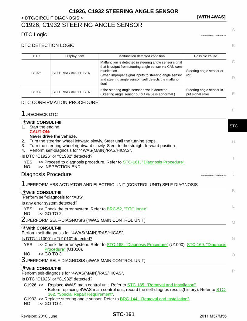
C1926, C1932 STEERING ANGLE SENSOR[WITH 4WAS]
C
D
E
F
H
I
J
K
L
M
A
B
TC
N
O
P
< DTC/CIRCUIT DIAGNOSIS >
S
C1926, C1932 STEERING ANGLE SENSOR
DTC Logic INFOID:0000000006045075
DTC DETECTION LOGIC
DTC CONFIRMATION PROCEDURE
1.RECHECK DTC
With CONSULT-III1. Start the engine.
CAUTION:Never drive the vehicle.
2. Turn the steering wheel leftward slowly. Steer until the turning stops.3. Turn the steering wheel rightward slowly. Steer to the straight-forward position.4. Perform self-diagnosis for “4WAS(MAIN)/RAS/HICAS”.Is DTC “C1926” or “C1932” detected?YES >> Proceed to diagnosis procedure. Refer to STC-161, "Diagnosis Procedure".NO >> INSPECTION END
Diagnosis Procedure INFOID:0000000006045076
1.PERFORM ABS ACTUATOR AND ELECTRIC UNIT (CONTROL UNIT) SELF-DIAGNOSIS
With CONSULT-III Perform self-diagnosis for “ABS”.Is any error system detected?YES >> Check the error system. Refer to BRC-52, "DTC Index".NO >> GO TO 2.
2.PERFORM SELF-DIAGNOSIS (4WAS MAIN CONTROL UNIT)
With CONSULT-IIIPerform self-diagnosis for “4WAS(MAIN)/RAS/HICAS”.Is DTC “U1000” or “U1010” detected?YES >> Check the error system. Refer to STC-168, "Diagnosis Procedure" (U1000), STC-169, "Diagnosis
Procedure" (U1010).NO >> GO TO 3.
3.PERFORM SELF-DIAGNOSIS (4WAS MAIN CONTROL UNIT)
With CONSULT-IIIPerform self-diagnosis for “4WAS(MAIN)/RAS/HICAS”.Is DTC “C1926” or “C1932” detected?C1926 >> Replace 4WAS main control unit. Refer to STC-185, "Removal and Installation".
• Before replacing 4WAS main control unit, record the self-diagnos results(history). Refer to STC-162, "Special Repair Requirement".
C1932 >> Replace steering angle sensor. Refer to BRC-144, "Removal and Installation".NO >> GO TO 4.
DTC Display Item Malfunction detected condition Possible cause
C1926 STEERING ANGLE SEN
Malfunction is detected in steering angle sensor signal that is output from steering angle sensor via CAN com-munication.(When improper signal inputs to steering angle sensor and steering angle sensor itself detects the malfunc-tion)
Steering angle sensor er-ror
C1932 STEERING ANGLE SENIf the steering angle sensor error is detected.(Steering angle sensor output value is abnormal.)
Steering angle sensor in-put signal error
STC-161Revision: 2010 June 2011 M37/M56
[WITH 4WAS]C1926, C1932 STEERING ANGLE SENSOR
< DTC/CIRCUIT DIAGNOSIS >
4.INFORMATION CHECK
With CONSULT-IIICheck the “DATA MONITOR” value of each DTC detected with the self-diagnosis function. Refer to STC-63,"Reference Value".Is each data the standard value?YES >> Check that there is no malfunction in each harness connector pin terminal or disconnection.NO >> Replace 4WAS main control unit. Refer to STC-185, "Removal and Installation".
• Before replacing 4WAS main control unit, record the self-diagnos results(history). Refer to STC-162, "Special Repair Requirement".
Special Repair Requirement INFOID:0000000006136408
Before replacing 4WAS main control unit, record the self-diagnosis results (history).CAUTION:• Never erase the memory (history) of self-diagnosis results when replacing 4WAS main control unit
after diagnosis.• Erase the memory of the self-diagnosis results (record) after printing out or recording all the values
of “DATA MONITOR”.
STC-162Revision: 2010 June 2011 M37/M56

C1930 4WAS FRONT CONTROL UNIT[WITH 4WAS]
C
D
E
F
H
I
J
K
L
M
A
B
TC
N
O
P
< DTC/CIRCUIT DIAGNOSIS >
S
C1930 4WAS FRONT CONTROL UNIT
DTC Logic INFOID:0000000006045078
DTC DETECTION LOGIC
DTC CONFIRMATION PROCEDURE
1.RECHECK DTC
With CONSULT-III1. Turn the ignition switch from OFF to ON.2. Perform self-diagnosis for “4WAS(MAIN)/RAS/HICAS”.Is DTC “C1930” detected?YES >> Proceed to diagnosis procedure. Refer to STC-163, "Diagnosis Procedure".NO >> INSPECTION END
Diagnosis Procedure INFOID:0000000006045079
1.PERFORM SELF-DIAGNOSIS (4WAS MAIN CONTROL UNIT)
With CONSULT-IIIPerform self-diagnosis for “4WAS(MAIN)/RAS/HICAS”.Is any DTC except “C1930” detected?YES >> Check the error system.NO >> Perform self-diagnosis for “4WAS(FRONT)”. Refer toSTC-48, "CONSULT-III Function
[4WAS(FRONT)]".
DTC Display Item Malfunction detected condition Possible cause
C1930 4WAS FRONT ECUAn error is detected on 4WAS front control unit side.(4WAS front control unit fail-safe mode)
4WAS front control unit fail-safe mode
STC-163Revision: 2010 June 2011 M37/M56

[WITH 4WAS]C1931 4WAS FRONT CONTROL UNIT COMMUNICATION
< DTC/CIRCUIT DIAGNOSIS >
C1931 4WAS FRONT CONTROL UNIT COMMUNICATION
Description INFOID:0000000006045080
• 4WAS front control unit and 4WAS main control unit transmit/receive information to/from each other for opti-mum control of the 4WAS system with the specified 4WAS system line (4WAS communication line) between4WAS front control unit and 4WAS main control unit.
• Be careful to repair wirings because 4WAS system specified line adopts twisted-pair wires. Refer to STC-33,"Precautions for Harness Repair".
DTC Logic INFOID:0000000006045081
DTC DETECTION LOGIC
*: Communication line between 4WAS front control unit and 4WAS main control unit.
DTC CONFIRMATION PROCEDURE
1.RECHECK DTC
With CONSULT-III1. Turn the ignition switch from OFF to ON.2. Perform self-diagnosis for “4WAS(MAIN)/RAS/HICAS”.Is DTC “C1931” detected?YES >> Proceed to diagnosis procedure. Refer to STC-164, "Diagnosis Procedure".NO >> INSPECTION END
Diagnosis Procedure INFOID:0000000006045082
1.CHECK COMMUNICATION LINE (1)
1. Turn the ignition switch OFF.2. Disconnect ABS actuator and electric unit (control unit) harness connector.3. Disconnect yaw rate/side/decel G sensor harness connector.4. Disconnect 4WAS front control unit harness connector.5. Disconnect 4WAS main control unit harness connector.6. Check the continuity between ABS actuator and electric unit (control unit) harness connector and yaw
rate/side G sensor harness connector.
Is the inspection result normal?YES >> GO TO 2.NO >> Repair or replace the harnesses and connectors. Refer to STC-33, "Precautions for Harness
Repair".
2.CHECK COMMUNICATION LINE (2)
Check the continuity between ABS actuator and electric unit (control unit) harness connector and the ground.
DTCItems
(CONSULT-III screen terms)Diagnostic item is detected when... Possible cause
C1931 4WAS FRONT ECU COMM
4WAS communication line* data communication error is detected.(An error signal is detected from 4WAS front control unit.)
4WAS communication line*/4WAS front control unit/4WAS main control unit error
ABS actuator and electric unit (control unit)
Yaw rate/side/decel G sensorContinuity
Connector Terminal Connector Terminal
E416
M1432
Existed16 3
STC-164Revision: 2010 June 2011 M37/M56

C1931 4WAS FRONT CONTROL UNIT COMMUNICATION[WITH 4WAS]
C
D
E
F
H
I
J
K
L
M
A
B
TC
N
O
P
< DTC/CIRCUIT DIAGNOSIS >
S
Is the inspection result normal?YES >> GO TO 3.NO >> Repair or replace the harnesses and connectors. Refer to STC-33, "Precautions for Harness
Repair".
3.CHECK COMMUNICATION LINE (3)
Check the continuity between ABS actuator and electric unit (control unit) harness connector.
Is the inspection result normal?YES >> GO TO 4.NO >> Repair or replace the harnesses and connectors. Refer to STC-33, "Precautions for Harness
Repair".
4.CHECK ABS ACTUATOR AND ELECTRIC UNIT (CONTROL UNIT)
Check the ABS actuator and electric unit (control unit) connector. Refer to STC-166, "Component Inspection[ABS Actuator and Electric Unit (Control Unit)]".Is the inspection result normal?YES >> GO TO 5.NO >> Replace ABS actuator and electric unit (control unit). Refer to BRC-141, "Removal and Installa-
tion".
5.CHECK YAW RATE/SIDE/DECEL G SENSOR
Check the between yaw rate/side/decel G sensor connector. Refer to STC-167, "Component Inspection (YawRate/Side/Decel G Sensor)".Is the inspection result normal?YES >> GO TO 6.NO >> Replace yaw rate/side G sensor. Refer to BRC-143, "Removal and Installation".
6.CHECK CAN DIAGNOSIS SUPPORT MONITOR (4WAS FRONT CONTROL UNIT)
With CONSULT-III1. Connect ABS actuator and electric unit (control unit) harness connector.2. Connect yaw rate/side/decel G sensor harness connector.3. Connect 4WAS front control unit harness connector.4. Connect 4WAS main control unit harness connector.5. Start the engine.
CAUTION:Never drive the vehicle.
6. Perform CAN diagnosis support monitor for “4WAS(FRONT)”.7. Check error history between 4WAS front control unit and 4WAS main control unit. Refer to STC-48,
"CONSULT-III Function [4WAS(FRONT)]".What is the indicated item?All items are “OK”>>GO TO 7.“TRANSMIT DIAG” is except “OK”>>GO TO 7.“4WAS(MAIN)” is except “OK”>>GO TO 8.
7.CHECK 4WAS FRONT CONTROL UNIT CIRCUIT
1. Turn the ignition switch OFF.
ABS actuator and electric unit (control unit) — Continuity
Connector Terminal
E416
Ground Not existed16
ABS actuator and electric unit (control unit)Continuity
Connector Terminal
E41 6 16 Not existed
STC-165Revision: 2010 June 2011 M37/M56

[WITH 4WAS]C1931 4WAS FRONT CONTROL UNIT COMMUNICATION
< DTC/CIRCUIT DIAGNOSIS >2. Disconnect 4WAS front control unit harness connector.3. Disconnect ABS actuator and electric unit (control unit) harness connector.4. Check the continuity between 4WAS front control unit harness connector and ABS actuator and electric
unit (control unit) harness connector.
5. Check that 4WAS front control unit connector No. 14 terminal and No. 25 are connected properly and notdeformed.
Is the inspection result normal?YES >> Replace 4WAS front control unit. Refer to STC-184, "Removal and Installation".
• Before replacing 4WAS front control unit, record the self-diagnosis results (histry). Refer toSTC-167, "Special Repair Requirement".
NO >> Repair or replace the harnesses and connectors. Refer to STC-33, "Precautions for HarnessRepair".
8.CHECK 4WAS MAIN CONTROL UNIT CIRCUIT
1. Turn the ignition switch OFF.2. Disconnect 4WAS main control unit harness connector.3. Disconnect ABS actuator and electric unit (control unit) harness connector.4. Check the continuity between 4WAS main control unit harness connector and ABS actuator and electric
unit (control unit) harness connector.
5. Check that 4WAS main control unit connector No. 31 terminal and No. 32 are connected properly and notdeformed.
Is the inspection result normal?YES >> Replace 4WAS main control unit. Refer to STC-185, "Removal and Installation".
• Before replacing 4WAS main control unit, record the self-diagnos results(history). Refer to STC-167, "Special Repair Requirement".
NO >> Repair or replace the harnesses and connectors. Refer to STC-33, "Precautions for HarnessRepair".
Component Inspection [ABS Actuator and Electric Unit (Control Unit)] INFOID:0000000006045083
1.CHECK ABS ACTUATOR AND ELECTRIC UNIT (CONTROL UNIT)
1. Turn the ignition switch OFF.2. Remove ABS actuator and electric unit (control unit). Refer toBRC-141, "Removal and Installation".3. Check the resistance between ABS actuator and electric unit (control unit) connector terminals.
Is the inspection result normal?YES >> INSPECTION ENDNO >> Replace ABS actuator and electric unit (control unit). Refer toBRC-141, "Removal and Installa-
tion".
4WAS front control unit ABS actuator and electric unit (control unit)Continuity
Connector Terminal Connector Terminal
M4214
E416
Existed25 16
4WAS main control unitABS actuator and electric unit (control
unit) Continuity
Connector Terminal Connector Terminal
B5431
E4116
Existed32 6
ABS actuator and electric unit (control unit) Resistance (Approx.)
Terminal
16 – 6 120 Ω
STC-166Revision: 2010 June 2011 M37/M56

C1931 4WAS FRONT CONTROL UNIT COMMUNICATION[WITH 4WAS]
C
D
E
F
H
I
J
K
L
M
A
B
TC
N
O
P
< DTC/CIRCUIT DIAGNOSIS >
S
Component Inspection (Yaw Rate/Side/Decel G Sensor) INFOID:0000000006045084
1.CHECK YAW RATE/SIDE/DECEL G SENSOR
1. Turn the ignition switch OFF.2. Remove yaw rate/side/decel G sensor. Refer to BRC-143, "Removal and Installation".3. Check the resistance between yaw rate/side/decel G sensor connector terminals.
Is the inspection result normal?YES >> INSPECTION ENDNO >> Replace yaw rate/side/decel G sensor. Refer to BRC-143, "Removal and Installation".
Special Repair Requirement INFOID:0000000006136409
Before replacing 4WAS main control unit, record the self-diagnosis results (history).CAUTION:• Never erase the memory (history) of self-diagnosis results when replacing 4WAS main control unit
after diagnosis.• Erase the memory of the self-diagnosis results (record) after printing out or recording all the values
of “DATA MONITOR”.
Yaw rate/side/decel G sensorResistance (Approx.)
Terminal
2 – 3 120 Ω
STC-167Revision: 2010 June 2011 M37/M56

[WITH 4WAS]U1000 CAN COMM CIRCUIT
< DTC/CIRCUIT DIAGNOSIS >
U1000 CAN COMM CIRCUIT
Description INFOID:0000000006045086
• CAN (Controller Area Network) is a serial communication line for real time application. It is an on-vehiclemultiplex communication line with high data communication speed and excellent error detection ability. Manyelectronic control units are equipped onto a vehicle, and each control unit shares information and links withother control units during operation (not independent). In CAN communication, control units are connectedwith 2 communication lines (CAN-H line, CAN-L line) allowing a high rate of information transmission withless wiring. Each control unit transmits/receives data but selectively reads required data only.
• 4WAS front control unit and 4WAS main control unit transmit/receive information to/from each other for opti-mum control of the 4WAS system with the specified 4WAS system line (4WAS communication line) between4WAS front control unit and 4WAS main control unit.
• Be careful to repair wirings because 4WAS system specified line adopts twisted-pair wires. Refer to STC-33,"Precautions for Harness Repair".
DTC Logic INFOID:0000000006045087
DTC DETECTION LOGIC
*: Communication line between 4WAS front control unit and 4WAS main control unit
DTC CONFIRMATION PROCEDURE
1.RECHECK DTC
With CONSULT-III1. Turn the ignition switch from OFF to ON.2. Perform self-diagnosis for “4WAS(MAIN)/RAS/HICAS”.Is DTC “U1000” detected?YES >> Proceed to diagnosis procedure. Refer to STC-168, "Diagnosis Procedure".NO >> INSPECTION END
Diagnosis Procedure INFOID:0000000006045088
1.CHECK SELF-DIAGNOSIS RESULT (4WAS MAIN CONTROL UNIT)
With CONSULT-IIICheck the self-diagnostic result.Is DTC “U1931” detected with “U1000”?YES >> Refer to STC-164, "Diagnosis Procedure" (C1931), STC-168, "Diagnosis Procedure" (U1000).NO >> Perform CAN diagnosis. Refer to LAN-25, "Trouble Diagnosis Flow Chart".
DTC Display Item Malfunction detected condition Possible cause
U1000 CAN COMM
When 4WAS main control unit is not transmitting or re-ceiving CAN communication signal for 2 seconds or more.
CAN communication er-ror
When 4WAS main control unit is not transmitting or re-ceiving 4WAS communication signal for 2 seconds or more.
4WAS communication line*/4WAS main control unit/4WAS front control unit error
STC-168Revision: 2010 June 2011 M37/M56

U1010 CONTROL UNIT (CAN)[WITH 4WAS]
C
D
E
F
H
I
J
K
L
M
A
B
TC
N
O
P
< DTC/CIRCUIT DIAGNOSIS >
S
U1010 CONTROL UNIT (CAN)
Description INFOID:0000000006045090
CAN (Controller Area Network) is a serial communication line for real time application. It is an on-vehicle mul-tiplex communication line with high data communication speed and excellent error detection ability. Many elec-tronic control units are equipped onto a vehicle, and each control unit shares information and links with othercontrol units during operation (not independent). In CAN communication, control units are connected with 2communication lines (CAN-H line, CAN-L line) allowing a high rate of information transmission with less wiring.Each control unit transmits/receives data but selectively reads required data only.
DTC Logic INFOID:0000000006045091
DTC DETECTION LOGIC
DTC CONFIRMATION PROCEDURE
1.RECHECK DTC
With CONSULT-III1. Turn the ignition switch from OFF to ON.2. Perform self-diagnosis for “4WAS(MAIN)/RAS/HICAS”.Is DTC “U1010” detected?YES >> Proceed to diagnosis procedure. Refer to STC-169, "Diagnosis Procedure".NO >> INSPECTION END
Diagnosis Procedure INFOID:0000000006045092
1.4WAS MAIN CONTROL UNIT
Check that there is no malfunction in 4WAS main control unit harness connector or disconnection.Is the inspection result normal? YES >> Replace 4WAS main control unit. Refer to STC-185, "Removal and Installation".
• Before replacing 4WAS main control unit, record the self-diagnos results(history). Refer to STC-169, "Special Repair Requirement".
NO >> Repair or replace the harnesses and connectors. Refer to STC-33, "Precautions for HarnessRepair".
Special Repair Requirement INFOID:0000000006136411
Before replacing 4WAS main control unit, record the self-diagnosis results (history).CAUTION:• Never erase the memory (history) of self-diagnosis results when replacing 4WAS main control unit
after diagnosis.• Erase the memory of the self-diagnosis results (record) after printing out or recording all the values
of “DATA MONITOR”.
DTC Display Item Malfunction detected condition Possible cause
U1010 CONTROL UNIT (CAN)When detecting error during the initial diagnosis of CAN controller of 4WAS main control unit.
CAN communication line/ 4WAS main control unit/ECM/ABS actuator and electric unit (control unit) error
STC-169Revision: 2010 June 2011 M37/M56

[WITH 4WAS]POWER SUPPLY AND GROUND CIRCUIT
< DTC/CIRCUIT DIAGNOSIS >
POWER SUPPLY AND GROUND CIRCUIT
Description INFOID:0000000006045094
4WAS system power supply
Diagnosis Procedure (4WAS Front Control Unit) INFOID:0000000006045095
1.CHECK 4WAS FRONT CONTROL UNIT POWER SUPPLY (1)
1. Turn the ignition switch OFF.2. Disconnect 4WAS front control unit harness connector.3. Check the voltage between 4WAS front control unit harness connector terminal and ground.
4. Turn the ignition switch ON.CAUTION:Never start the engine.
5. Check the voltage between 4WAS front control unit harness connector terminal and ground.
Is the inspection result normal?YES >> GO TO 3.NO >> GO TO 2.
2.CHECK 4WAS FRONT CONTROL UNIT POWER SUPPLY (2)
1. Turn the ignition switch OFF.2. Check the 40A fusible link (Q).3. Check the harness for open or short between 4WAS front control unit harness connector No.11 terminal
and 40A fusible link (Q).Is the inspection result normal?YES >> Perform the trouble diagnosis for power supply circuit. Refer to PG-11, "Wiring Diagram - BAT-
TERY POWER SUPPLY -".NO >> Repair or replace error-detected parts.
3.CHECK 4WAS FRONT CONTROL UNIT POWER SUPPLY (3)
1. Turn the ignition switch OFF.2. Disconnect 4WAS front control unit harness connector.3. Check the voltage between 4WAS front control unit harness connector terminal and ground.
4. Turn the ignition switch ON.CAUTION:Never start the engine.
5. Check the voltage between 4WAS front control unit harness connector terminal and ground.
4WAS front control unit— Voltage (Approx.)
Connector Terminal
M41 11 Ground Battery voltage
4WAS front control unit— Voltage (Approx.)
Connector Terminal
M41 11 Ground Battery voltage
4WAS front control unit— Voltage (Approx.)
Connector Terminal
M42 15 Ground 0 V
4WAS front control unit— Voltage (Approx.)
Connector Terminal
M42 15 Ground Battery voltage
STC-170Revision: 2010 June 2011 M37/M56

POWER SUPPLY AND GROUND CIRCUIT[WITH 4WAS]
C
D
E
F
H
I
J
K
L
M
A
B
TC
N
O
P
< DTC/CIRCUIT DIAGNOSIS >
S
Is the inspection result normal?YES >> GO TO 5.NO >> GO TO 4.
4.CHECK 4WAS FRONT CONTROL UNIT POWER SUPPLY (4)
1. Turn the ignition switch OFF.2. Check the 10A fuse (#3).3. Disconnect fuse block (J/B) harness connector.4. Check the continuity between 4WAS front control unit harness connector and fuse block (J/B).
5. Check the continuity between 4WAS front control unit harness connector and the ground.
Is the inspection result normal?YES >> Perform the trouble diagnosis for ignition power supply circuit. Refer to PG-84, "Wiring Diagram -
IGNITION POWER SUPPLY -".NO >> Repair or replace error-detected parts.
5.CHECK 4WAS FRONT CONTROL UNIT GROUND
Check the continuity between 4WAS front control unit harness connector terminal and the ground.
Is the inspection result normal?YES >> INSPECTION ENDNO >> Repair or replace the harnesses and connectors.
Diagnosis Procedure (4WAS Main Control Unit) INFOID:0000000006045096
1.CHECK 4WAS MAIN CONTROL UNIT GROUND
1. Turn the ignition switch OFF.2. Disconnect 4WAS main control unit harness connector.3. Check the continuity between 4WAS main control unit harness connector terminal and the ground.
Is the inspection result normal?YES >> GO TO 2.NO >> Repair or replace the harnesses and connectors.
2.CHECK 4WAS MAIN CONTROL UNIT POWER SUPPLY (1)
1. Check the voltage between 4WAS main control unit harness connector terminal and ground.
4WAS front control unit Fuse block (J/B)Continuity
Connector Terminal Connector Terminal
M42 15 M1 2A Existed
4WAS front control unit— Continuity
Connector Terminal
M42 15 Ground Not existed
4WAS front control unit— Continuity
Connector Terminal
M41 12
Ground ExistedM42
18
34
4WAS main control unit— Continuity
Connector Terminal
B5434
Ground Existed40
STC-171Revision: 2010 June 2011 M37/M56

[WITH 4WAS]POWER SUPPLY AND GROUND CIRCUIT
< DTC/CIRCUIT DIAGNOSIS >
2. Turn the ignition switch ON.CAUTION:Never start the engine.
3. Check the voltage between 4WAS main control unit harness connector terminal and ground.
Is the inspection result normal?YES >> GO TO 4.NO >> GO TO 3.
3.CHECK 4WAS MAIN CONTROL UNIT POWER SUPPLY (2)
1. Turn the ignition switch OFF.2. Check the 10A fuse (#46).3. Disconnect IPDM E/R harness connector.4. Check the continuity between 4WAS main control unit harness connector and IPDM E/R harness connec-
tor.
5. Check the continuity between 4WAS main control unit harness connector and ground.
Is the inspection result normal?YES >> Perform the trouble diagnosis for ignition power supply circuit. Refer to PG-84, "Wiring Diagram -
IGNITION POWER SUPPLY -".NO >> Repair or replace error-detected parts.
4.CHECK 4WAS REAR MOTOR POWER SUPPLY CIRCUIT (1)
1. Remove 4WAS rear motor relay.2. Check the continuity between 4WAS rear motor relay harness connector and ground.
3. Check the continuity between 4WAS main control unit harness connector and IPDM E/R harness connec-tor.
Is the inspection result normal?
4WAS main control unit— Voltage (Approx.)
Connector Terminal
B54 27 Ground 0 V
4WAS main control unit— Voltage (Approx.)
Connector Terminal
B54 27 Ground Battery voltage
4WAS main control unit IPDM E/RContinuity
Connector Terminal Connector Terminal
B54 27 E5 12 Existed
4WAS main control unit— Continuity
Connector Terminal
B54 27 Ground Not existed
4WAS rear motor relay— Continuity
Connector Terminal
B532
GroundExisted
1 Not existed
4WAS rear motor relay 4WAS main control unitContinuity
Connector Terminal Connector Terminal
B53 1 B54 25 Existed
STC-172Revision: 2010 June 2011 M37/M56

POWER SUPPLY AND GROUND CIRCUIT[WITH 4WAS]
C
D
E
F
H
I
J
K
L
M
A
B
TC
N
O
P
< DTC/CIRCUIT DIAGNOSIS >
S
YES >> GO TO 5.NO >> Repair or replace error-detected parts.
5.CHECK 4WAS REAR MOTOR POWER SUPPLY CIRCUIT (2)
1. Check 20A fusible link (#37).2. Check the harness for open or short between 4WAS front control unit harness connector No.3 terminal
and 20A fusible link (#37).Is the inspection result normal?YES >> GO TO 6.NO >> Repair or replace error-detected parts.
6.CHECK 4WAS REAR MOTOR POWER SUPPLY CIRCUIT (3)
1. Turn the ignition switch ON.CAUTION:Never start the engine.
2. Check the voltage between 4WAS main control unit harness connectors and the ground.
3. Turn the ignition switch OFF.Is the inspection result normal?YES >> GO TO 7.NO >> Replace 4WAS main control unit. Refer to STC-185, "Removal and Installation".
• Before replacing 4WAS main control unit, record the self-diagnos results(history). Refer to STC-174, "Special Repair Requirement".
7.CHECK 4WAS REAR MOTOR RELAY
Check 4WAS rear motor relay. Refer to STC-173, "Component Inspection".Is the inspection result normal?YES >> GO TO 8.NO >> Replace 4WAS rear motor relay.
8.CHECK 4WAS REAR MOTOR POWER SUPPLY
1. Connect 4WAS main control unit harness connector.2. Install 4WAS rear motor relay.3. Turn the ignition switch ON.
CAUTION:Never start the engine.
4. Check the voltage between 4WAS main control unit harness connectors and the ground.
Is the inspection result normal?YES >> INSPECTION END.NO >> Replace 4WAS main control unit. Refer to STC-185, "Removal and Installation".
• Before replacing 4WAS main control unit, record the self-diagnos results(history). Refer to STC-174, "Special Repair Requirement".
Component Inspection INFOID:0000000006134039
1.CHECK 4WAS REAR MOTOR RELAY
1. Turn the ignition switch OFF.2. Remove 4WAS rear motor relay connector.3. Apply 12 V to 4WAS rear motor relay connector No. 1 terminal and No. 2 terminal.
4WAS main control unit— Voltage (Approx.)
Connector Terminal
B54 25 Ground Battery voltage
4WAS main control unit— Voltage (Approx.)
Connector Terminal
B54 37 Ground Battery voltage
STC-173Revision: 2010 June 2011 M37/M56

[WITH 4WAS]POWER SUPPLY AND GROUND CIRCUIT
< DTC/CIRCUIT DIAGNOSIS >CAUTION:• Never make the terminals short.• Connect the fuse between the terminals when applying the voltage.
4. Check the continuity between 4WAS rear motor relay connector terminals.
5. Check the resistance between 4WAS rear motor relay connector terminals.
Is the inspection result normal?YES >> INSPECTION ENDNO >> Replace 4WAS rear motor relay.
Special Repair Requirement INFOID:0000000006136420
Before replacing 4WAS main control unit, record the self-diagnosis results (history).CAUTION:• Never erase the memory (history) of self-diagnosis results when replacing 4WAS main control unit
after diagnosis.• Erase the memory of the self-diagnosis results (record) after printing out or recording all the values
of “DATA MONITOR”.
4WAS rear motor relayContinuity
Terminal Condition
3 – 5
Apply the voltage between No. 1 ter-minal and No. 2 terminal.
Existed
Do not apply the voltage between No. 1 terminal and No. 2 terminal.
Not existed
4WAS rear motor relay Resistance (Ap-prox.)Terminal
1 2 50 Ω
STC-174Revision: 2010 June 2011 M37/M56
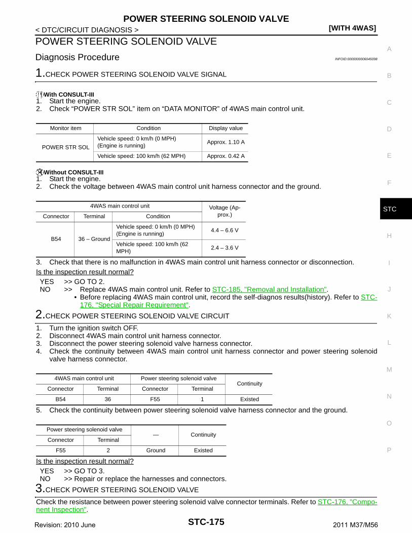
POWER STEERING SOLENOID VALVE[WITH 4WAS]
C
D
E
F
H
I
J
K
L
M
A
B
TC
N
O
P
< DTC/CIRCUIT DIAGNOSIS >
S
POWER STEERING SOLENOID VALVE
Diagnosis Procedure INFOID:0000000006045098
1.CHECK POWER STEERING SOLENOID VALVE SIGNAL
With CONSULT-III1. Start the engine.2. Check “POWER STR SOL” item on “DATA MONITOR” of 4WAS main control unit.
Without CONSULT-III1. Start the engine.2. Check the voltage between 4WAS main control unit harness connector and the ground.
3. Check that there is no malfunction in 4WAS main control unit harness connector or disconnection.Is the inspection result normal?YES >> GO TO 2.NO >> Replace 4WAS main control unit. Refer to STC-185, "Removal and Installation".
• Before replacing 4WAS main control unit, record the self-diagnos results(history). Refer to STC-176, "Special Repair Requirement".
2.CHECK POWER STEERING SOLENOID VALVE CIRCUIT
1. Turn the ignition switch OFF.2. Disconnect 4WAS main control unit harness connector.3. Disconnect the power steering solenoid valve harness connector.4. Check the continuity between 4WAS main control unit harness connector and power steering solenoid
valve harness connector.
5. Check the continuity between power steering solenoid valve harness connector and the ground.
Is the inspection result normal?YES >> GO TO 3.NO >> Repair or replace the harnesses and connectors.
3.CHECK POWER STEERING SOLENOID VALVE
Check the resistance between power steering solenoid valve connector terminals. Refer to STC-176, "Compo-nent Inspection".
Monitor item Condition Display value
POWER STR SOL
Vehicle speed: 0 km/h (0 MPH)(Engine is running)
Approx. 1.10 A
Vehicle speed: 100 km/h (62 MPH) Approx. 0.42 A
4WAS main control unit Voltage (Ap-prox.)Connector Terminal Condition
B54 36 – Ground
Vehicle speed: 0 km/h (0 MPH)(Engine is running)
4.4 – 6.6 V
Vehicle speed: 100 km/h (62 MPH)
2.4 – 3.6 V
4WAS main control unit Power steering solenoid valveContinuity
Connector Terminal Connector Terminal
B54 36 F55 1 Existed
Power steering solenoid valve— Continuity
Connector Terminal
F55 2 Ground Existed
STC-175Revision: 2010 June 2011 M37/M56

[WITH 4WAS]POWER STEERING SOLENOID VALVE
< DTC/CIRCUIT DIAGNOSIS >Is the inspection result normal?YES >> INSPECTION ENDNO >> Repair gear-sub assembly. Refer to ST-46, "2WD : Disassembly and Assembly".
Component Inspection INFOID:0000000006045099
1.CHECK POWER STEERING SOLENOID VALVE
1. Check the resistance between power steering solenoid valve connector terminals.
2. Check for click sound (power steering solenoid valve activation sound) when applying approximately 12 Vbetween the power steering solenoid valve connector terminals.CAUTION:• Never make the terminals short.• Assign the positive terminal to No. 1 terminal, and the negative terminal to No. 2 terminal. Con-
nect the fuse between the terminals when applying the voltage.Is the inspection result normal?YES >> INSPECTION ENDNO >> Repair gear-sub assembly. Refer to ST-46, "2WD : Disassembly and Assembly".
Special Repair Requirement INFOID:0000000006137501
Before replacing 4WAS main control unit, record the self-diagnosis results (history).CAUTION:• Never erase the memory (history) of self-diagnosis results when replacing 4WAS main control unit
after diagnosis.• Erase the memory of the self-diagnosis results (record) after printing out or recording all the values
of “DATA MONITOR”.
Power steering solenoid valve Resistance (Ap-prox.)Terminal
1 2 4 – 6 Ω
STC-176Revision: 2010 June 2011 M37/M56

4WAS WARNING LAMP[WITH 4WAS]
C
D
E
F
H
I
J
K
L
M
A
B
TC
N
O
P
< DTC/CIRCUIT DIAGNOSIS >
S
4WAS WARNING LAMP
Diagnosis Procedure INFOID:0000000006045100
1.PERFORM UNIFIED METER AND A/C AMP. SELF-DIAGNOSIS
With CONSULT-III Perform the self-diagnosis for “METER/M&A”.Is any error system detected?YES >> Check the error system. Refer to MWI-43, "DTC Index".NO >> GO TO 2.
2.PERFORM SELF-DIAGNOSIS (4WAS MAIN CONTROL UNIT)
With CONSULT-IIIPerform self-diagnosis for “4WAS(MAIN)/RAS/HICAS”.Is DTC “U1000” or “U1010” detected?YES >> Check the error system. Refer to STC-168, "Diagnosis Procedure" (U1000), STC-169, "Diagnosis
Procedure" (U1010).NO >> GO TO 3.
3.CHECK 4WAS WARNING LAMP SIGNAL
With CONSULT-III1. Turn the ignition switch ON.
CAUTION:Never start the engine.
2. Check “WARNING LAMP” item on DATA MONITOR for “4WAS(MAIN)/RAS/HICAS”.Does the item on “DATA MONITOR” indicate “On”?YES >> GO TO 4.NO >> Replace 4WAS main control unit. Refer to STC-185, "Removal and Installation".
• Before replacing 4WAS main control unit, record the self-diagnos results(history). Refer to STC-177, "Special Repair Requirement".
4.CHECK COMBINATION METER
With CONSULT-IIIPerform the trouble diagnosis of the combination meter. Refer to MWI-70, "COMBINATION METER : Diagno-sis Procedure".Is the inspection result normal?YES >> INSPECTION ENDNO >> Replace the combination meter. Refer to MWI-90, "Removal and Installation".
Special Repair Requirement INFOID:0000000006137502
Before replacing 4WAS main control unit, record the self-diagnosis results (history).CAUTION:• Never erase the memory (history) of self-diagnosis results when replacing 4WAS main control unit
after diagnosis.• Erase the memory of the self-diagnosis results (record) after printing out or recording all the values
of “DATA MONITOR”.
STC-177Revision: 2010 June 2011 M37/M56
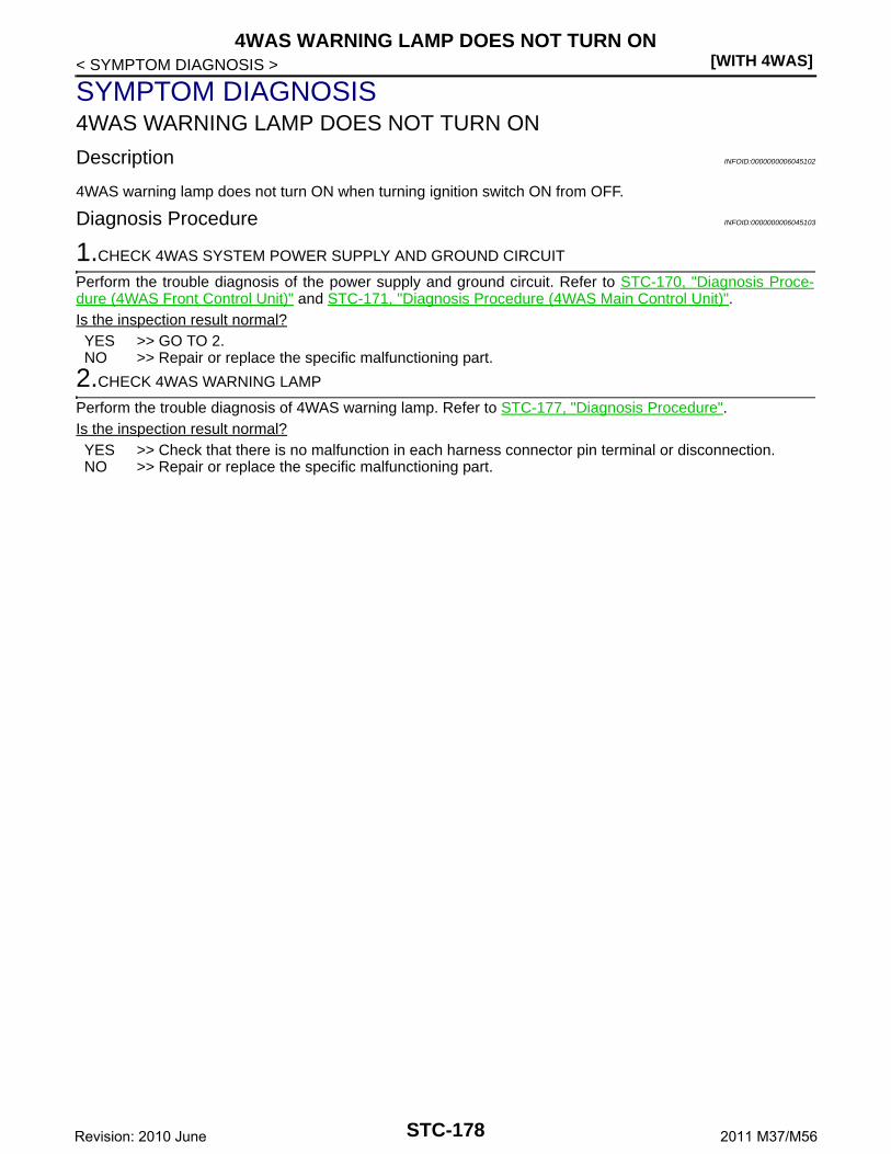
[WITH 4WAS]4WAS WARNING LAMP DOES NOT TURN ON
< SYMPTOM DIAGNOSIS >
SYMPTOM DIAGNOSIS4WAS WARNING LAMP DOES NOT TURN ON
Description INFOID:0000000006045102
4WAS warning lamp does not turn ON when turning ignition switch ON from OFF.
Diagnosis Procedure INFOID:0000000006045103
1.CHECK 4WAS SYSTEM POWER SUPPLY AND GROUND CIRCUIT
Perform the trouble diagnosis of the power supply and ground circuit. Refer to STC-170, "Diagnosis Proce-dure (4WAS Front Control Unit)" and STC-171, "Diagnosis Procedure (4WAS Main Control Unit)".Is the inspection result normal?YES >> GO TO 2.NO >> Repair or replace the specific malfunctioning part.
2.CHECK 4WAS WARNING LAMP
Perform the trouble diagnosis of 4WAS warning lamp. Refer to STC-177, "Diagnosis Procedure".Is the inspection result normal?YES >> Check that there is no malfunction in each harness connector pin terminal or disconnection.NO >> Repair or replace the specific malfunctioning part.
STC-178Revision: 2010 June 2011 M37/M56
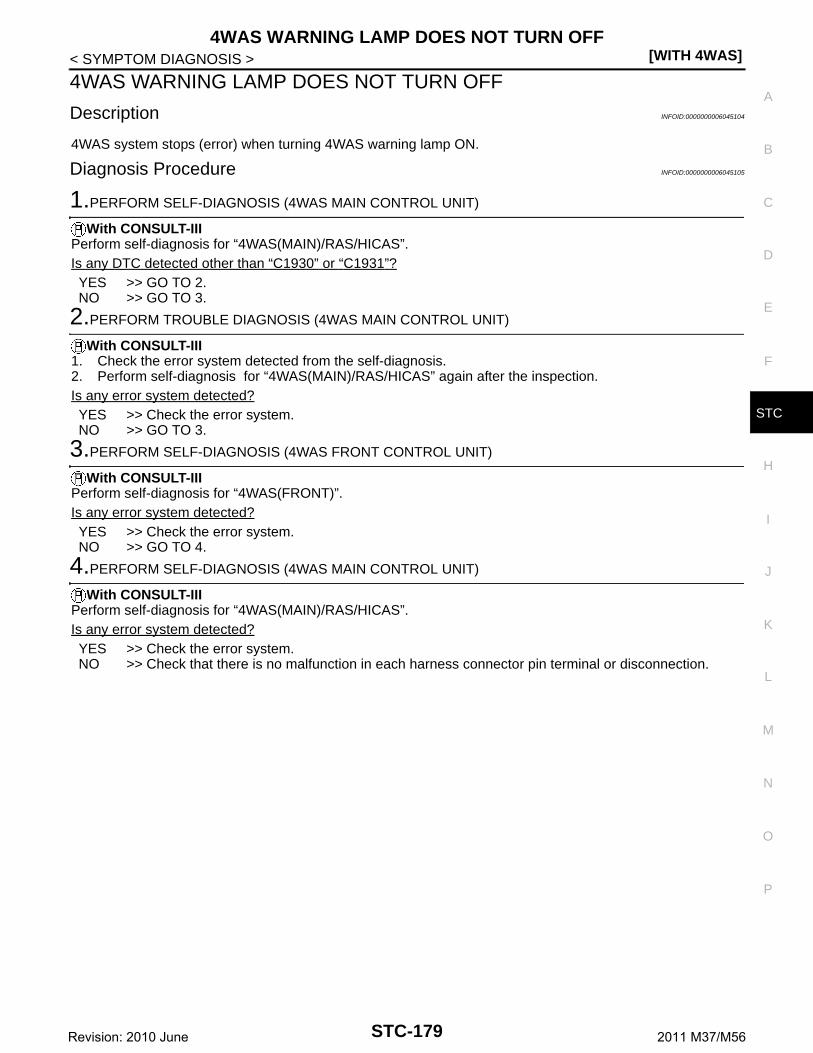
4WAS WARNING LAMP DOES NOT TURN OFF[WITH 4WAS]
C
D
E
F
H
I
J
K
L
M
A
B
TC
N
O
P
< SYMPTOM DIAGNOSIS >
S
4WAS WARNING LAMP DOES NOT TURN OFF
Description INFOID:0000000006045104
4WAS system stops (error) when turning 4WAS warning lamp ON.
Diagnosis Procedure INFOID:0000000006045105
1.PERFORM SELF-DIAGNOSIS (4WAS MAIN CONTROL UNIT)
With CONSULT-IIIPerform self-diagnosis for “4WAS(MAIN)/RAS/HICAS”.Is any DTC detected other than “C1930” or “C1931”?YES >> GO TO 2.NO >> GO TO 3.
2.PERFORM TROUBLE DIAGNOSIS (4WAS MAIN CONTROL UNIT)
With CONSULT-III1. Check the error system detected from the self-diagnosis.2. Perform self-diagnosis for “4WAS(MAIN)/RAS/HICAS” again after the inspection.Is any error system detected?YES >> Check the error system.NO >> GO TO 3.
3.PERFORM SELF-DIAGNOSIS (4WAS FRONT CONTROL UNIT)
With CONSULT-IIIPerform self-diagnosis for “4WAS(FRONT)”.Is any error system detected?YES >> Check the error system.NO >> GO TO 4.
4.PERFORM SELF-DIAGNOSIS (4WAS MAIN CONTROL UNIT)
With CONSULT-IIIPerform self-diagnosis for “4WAS(MAIN)/RAS/HICAS”.Is any error system detected?YES >> Check the error system.NO >> Check that there is no malfunction in each harness connector pin terminal or disconnection.
STC-179Revision: 2010 June 2011 M37/M56

[WITH 4WAS]STEERING WHEEL MISS ALIGNMENT
< SYMPTOM DIAGNOSIS >
STEERING WHEEL MISS ALIGNMENT
Description INFOID:0000000006045106
• The steering wheel position (center) is in the wrong position at driving.• 4WAS system stops temporarily.
NOTE:• The steering wheel position (center) is in the wrong position under the following condition. (4WAS system
is in the protection mode. This is normal status.)- When steering frequently- When driving on a rough road- When the assist of power steering is not sufficient- When the battery voltage is weak- When driving under the status that there is a difference in the steering wheel
Diagnosis Procedure INFOID:0000000006045107
1.CHECK SYMPTOM
Never drive the vehicle in the straight-ahead position after driving for a period of time. Does the steering wheel position (center) misalign?YES >> INSPECTION END (Entered in 4WAS system protection function mode in past. 4WAS system is
normal at present.)NO >> GO TO 2.
2.4WAS FRONT ACTUATOR INITIALIZATION
1. Start the engine.CAUTION:Never drive the vehicle.
2. Steer 90° leftward slowly. Steer 90° rightward and return the steering wheel to the straight-ahead position.Repeat the above 10 times.
3. Stop the vehicle in the straight-ahead position after driving for a period of time. Does the steering wheel position (center) misalign?YES >> INSPECTION END (Entered in 4WAS system protection function mode in past. 4WAS system is
normal at present.)NO >> GO TO 3.
3.4WAS SYSTEM CONDITION
With CONSULT-III1. Start the engine.
CAUTION:Never drive the vehicle.
2. Check “EX OPERAT” item on “DATA MONITOR” for “4WAS(FRONT)”.Does the item on “DATA MONITOR” indicate “On”?YES >> GO TO 7.NO >> GO TO 4.
4.CHECK STEERING SYSTEM
Check the steering system. Refer to ST-31, "Inspection" and ST-15, "Inspection".Is the inspection result normal?YES >> GO TO 5.NO >> Repair or replace the specific malfunctioning part.
5.CHECK WHEEL ALIGNMENT
Check the wheel alignment. Refer to FSU-8, "Inspection" (front side), RSU-6, "Inspection" (rear side).Is the inspection result normal?YES >> GO TO 6.NO >> Repair or replace the specific malfunctioning part.
STC-180Revision: 2010 June 2011 M37/M56

STEERING WHEEL MISS ALIGNMENT[WITH 4WAS]
C
D
E
F
H
I
J
K
L
M
A
B
TC
N
O
P
< SYMPTOM DIAGNOSIS >
S
6.PERFORM 4WAS FRONT ACTUATOR ADJUSTMENT
1. Perform 4WAS front actuator adjustment. Refer to STC-88, "Work Procedure (Pattern 3)".2. Stop the vehicle in the straight-ahead position after driving for a period of time. Does the steering wheel position (center) misalign?YES >> INSPECTION END.NO >> GO TO 7.
7.CHECK 4WAS SYSTEM IGNITION POWER SUPPLY
Perform the trouble diagnosis of the ignition power supply. Refer to STC-103, "Diagnosis Procedure".Is the inspection result normal?YES >> GO TO 8.NO >> Repair or replace the specific malfunctioning part.
8.CHECK 4WAS SYSTEM 4WAS FRONT MOTOR POWER SUPPLY
Perform the trouble diagnosis of 4WAS front motor power supply. Refer to STC-105, "Diagnosis Procedure".Is the inspection result normal?YES >> GO TO 9.NO >> Repair or replace the specific malfunctioning part.
9.CHECK 4WAS SYSTEM HISTORY
With CONSULT-III1. Turn the ignition switch OFF.
CAUTION:Wait 30 minutes or more after turning the ignition switch OFF.
2. Start the engine.CAUTION:Never drive the vehicle.
3. Check “EX OPERAT” on 4WAS front control unit “DATA MONITOR”.Is the value of DATA MONITOR “On”?YES >> Replace 4WAS front control unit. Refer to STC-184, "Removal and Installation".NO >> INSPECTION END
STC-181Revision: 2010 June 2011 M37/M56

[WITH 4WAS]STEERING SYSTEM VIBRATION AND NOISE
< SYMPTOM DIAGNOSIS >
STEERING SYSTEM VIBRATION AND NOISE
Description INFOID:0000000006045108
Vibration or noise occurs in the steering wheel while driving the vehicle.NOTE:Vibration or noise occurs in the steering wheel in the following conditions. (4WAS system is not malfunction.)• 4WAS system starts and ends (when the engine speed is ON⇔OFF).• System protection mode- When steering frequently- When driving on a rough road- When the assist of power steering is not sufficient- When the battery voltage is weak
Diagnosis Procedure INFOID:0000000006045109
1.CHECK 4WAS SYSTEM
With CONSULT-III1. Start the engine.
CAUTION:Never drive the vehicle.
2. Check “OVRLD JDG FLG”, “ACT PRTCT FLG”, “ECU PRTCT FLG”,“LOW VOLT FLG”, “HIGH VOLTFLG”, “EX OPERAT” items on “DATA MONITOR” for 4WAS(FRONT).
Does all items on “DATA MONITOR” indicate “Off”?YES >> INSPECTION END (Vibration and sound occurs in 4WAS system protection function mode. This
is normal.)NO >> GO TO 2.
2.STOP 4WAS FRONT ACTUATOR CONTROL
1. Turn the ignition switch OFF.2. Disconnect 4WAS front actuator harness connector.
CAUTION:Disconnect 4WAS front actuator harness connector 10 minutes after turning the ignition switchOFF.
3. Drive the vehicle for a period of time. Check the symptom.CAUTION:Erase the self-diagnosis memory after the inspection is completed to detect 4WAS front controlunit DTC “C1661”. [Erase the self diagnosis memory of 4WAS main control unit, ABS actuator andelectric unit (control unit) and ADAS control unit simultaneously.]
Does symptom not occur?YES >> Replace 4WAS front actuator. Refer to ST-41, "WITH 4WAS : Removal and Installation".NO >> Perform the steering system. Refer to ST-31, "Inspection" and ST-15, "Inspection".
STC-182Revision: 2010 June 2011 M37/M56

UNBALANCE STEERING WHEEL TURNING FORCE (TORQUE VARIATION)[WITH 4WAS]
C
D
E
F
H
I
J
K
L
M
A
B
TC
N
O
P
< SYMPTOM DIAGNOSIS >
S
UNBALANCE STEERING WHEEL TURNING FORCE (TORQUE VARIA-TION)
Description INFOID:0000000006045110
• The steering force does not change smoothly according to the vehicle speed.- The steering force is heavy when steering.- The steering force is light when driving at high speed.
Diagnosis Procedure INFOID:0000000006045111
1.CHECK 4WAS SYSTEM VEHICLE SPEED SIGNAL
Perform the trouble diagnosis of the vehicle speed signal. Refer to STC-151, "Diagnosis Procedure".Is the inspection result normal?YES >> GO TO 2.NO >> Repair or replace the specific malfunctioning part.
2.CHECK STEERING SYSTEM
Check the steering system. Refer to ST-31, "Inspection" and ST-15, "Inspection".Is the inspection result normal?YES >> GO TO 3.NO >> Repair or replace the specific malfunctioning part.
3.CHECK 4WAS SYSTEM POWER STEERING SOLENOID VALVE
Perform the trouble diagnosis of the power steering solenoid valve. Refer to STC-175, "Diagnosis Procedure".Is the inspection result normal?YES >> Check that there is no malfunction in each harness connector pin terminal or disconnection.NO >> Repair or replace the specific malfunctioning part.
STC-183Revision: 2010 June 2011 M37/M56

[WITH 4WAS]4WAS FRONT CONTROL UNIT
< REMOVAL AND INSTALLATION >
REMOVAL AND INSTALLATION4WAS FRONT CONTROL UNIT
Removal and Installation INFOID:0000000006045112
REMOVALCAUTION:• Never erase the memory (history) of self-diagnosis results when replacing 4WAS front control unit
after diagnosis.• Erase the memory of the self-diagnosis results (record) after printing out or recording all the values
of “DATA MONITOR”.1. Turn the ignition switch OFF.2. Remove the glove box. Refer to IP-13, "Removal and Installation".3. Remove the instrument lower panel RH. Refer to IP-13, "Removal and Installation".4. Disconnect 4WAS front control unit connectors.
CAUTION:Disconnect 4WAS front control unit connectors 10 minutes after turning the ignition switch OFF.
5. Remove the bolts of 4WAS front control unit.6. Remove the 4WAS front control unit.
INSTALLATIONNote following, and install in the reverse order of removal.• Perform 4WAS front actuator adjustment after replacing 4WAS front control unit. Refer to STC-88, "Work
Procedure (Pattern 3)".
STC-184Revision: 2010 June 2011 M37/M56

4WAS MAIN CONTROL UNIT[WITH 4WAS]
C
D
E
F
H
I
J
K
L
M
A
B
TC
N
O
P
< REMOVAL AND INSTALLATION >
S
4WAS MAIN CONTROL UNIT
Removal and Installation INFOID:0000000006045113
REMOVALCAUTION:• Never erase the memory (history) of self-diagnosis results when replacing 4WAS main control unit
after diagnosis.• Erase the memory of the self-diagnosis results (record) after printing out or recording all the values
of “DATA MONITOR”.1. Turn the ignition switch OFF.2. Remove the trunk side finisher (LH). Refer to INT-54, "TRUNK SIDE FINISHER : Removal and Installa-
tion".3. Disconnect 4WAS main control unit connectors, 4WAS rear motor relay connector and noise suppressor
connectors.4. Remove the 4WAS main control unit bolts.5. Remove the 4WAS main control unit.
INSTALLATIONInstall in the reverse order of removal.
STC-185Revision: 2010 June 2011 M37/M56

[WITH 4WAS]4WAS FRONT ACTUATOR ASSEMBLY
< REMOVAL AND INSTALLATION >
4WAS FRONT ACTUATOR ASSEMBLY
Removal and Installation INFOID:0000000006045114
• For removal and installation, refer to ST-41, "WITH 4WAS : Removal and Installation".• Perform 4WAS front actuator adjustment after replacing 4WAS front actuator. Refer to STC-87, "Work Pro-
cedure (Pattern 2)".
STC-186Revision: 2010 June 2011 M37/M56

4WAS REAR ACTUATOR ASSEMBLY[WITH 4WAS]
C
D
E
F
H
I
J
K
L
M
A
B
TC
N
O
P
< REMOVAL AND INSTALLATION >
S
4WAS REAR ACTUATOR ASSEMBLY
Exploded View INFOID:0000000006045115
Removal and Installation INFOID:0000000006045116
REMOVAL1. Remove fixing bolts and nuts of 4WAS rear actuator from lower link. Refer to RSU-17, "Removal and
Installation".2. Disconnect harness connector from 4WAS rear actuator and rear suspension member.3. Remove fixing bolts and nuts of 4WAS rear actuator, and then remove 4WAS rear actuator from rear sus-
pension member.
INSTALLATIONNote the following, and install in the reverse order of removal.• When installing 4WAS rear actuator to rear suspension member, check the mounting surfaces of 4WAS rear
actuator and rear suspension member for oil, dirt, sand, or other foreign materials.• Check rear wheel alignment. Refer to RSU-6, "Inspection".
1. 4WAS rear actuator assembly
Refer to GI-4, "Components" for symbols in the figure.
JSGIA0818GB
STC-187Revision: 2010 June 2011 M37/M56