
Steering control system for vessels using CAN bus · PDF fileSteering control system for...
7
iCC 2012 CAN in Automation 07-1 Steering control system for vessels using CAN-bus Dr.-Ing. Michael Ruff, Raytheon-Anschütz GmbH A steering control system based on CAN-bus technology was developed in accordance to safe operations for vessels on sea. With CAN-bus technology we reduced the efforts of cabling with highest reliability on sea. The paper describes the steering and navigation system of vessels with respect to automatic control. All data (reference values, measured values, alarm handling, configuration values) of a steering system with certain devices (e.g. Rudder, Feedback Unit, Gyro, Autopilot, etc.) are transmitted via CAN-Bus in real time. A short introduction explains the problems of steering vessels. A central component of the steering system is the autopilot. Its main task is to keep the ship on heading given by the helmsman or an Electronic Chart Display information system (ECDIS). The main part describes the design of the required controller. Closing the paper with measurement results of the autopilot demonstrate exemplary the safe operations. 1 Introduction 90% of the world wide goods traffic is covered by maritime traffic. A modern merchant vessel must be cost effective in order to survive the ever increasing pressure of a financially oriented industry. A good automatic pilot can improve the profit margin of a vessel in two ways. Firstly it enables a reduction to be made in the number of ships personnel and secondly a considerable in saving the fuel can be achieved if the vessel makes good its course with little deviation. A very important component of a ship is the rudder and steering system. The steering system as shown in Figure 1 is one of the most critical systems on board. Therefore the requirements concerning the reliability of the data transfer are very high. The important data have to arrive in time. Figure 1. Block diagram of a steering system The gyro as a sensor determines the actual heading of a vessel and the rate of turn r is measured by a correspondent sensor or using the correlation between r and : (1) = !" !" = In addition to these measured values the belonging reference values and the track data of an ECDIS are the input values of the controllers of an autopilot. The output of the autopilot is the reference value ∗ of the rudder position. This value is the input value of an amplifier which causes the rudder to move. The actual rudder position δ is measured by a feedback unit. The measured value is
Transcript of Steering control system for vessels using CAN bus · PDF fileSteering control system for...

iCC 2012 CAN in Automation
07-1
Steering control system for vessels using CAN-bus Dr.-Ing. Michael Ruff, Raytheon-Anschütz GmbH
A steering control system based on CAN-bus technology was developed in accordance to safe operations for vessels on sea. With CAN-bus technology we reduced the efforts of cabling with highest reliability on sea. The paper describes the steering and navigation system of vessels with respect to automatic control. All data (reference values, measured values, alarm handling, configuration values) of a steering system with certain devices (e.g. Rudder, Feedback Unit, Gyro, Autopilot, etc.) are transmitted via CAN-Bus in real time. A short introduction explains the problems of steering vessels. A central component of the steering system is the autopilot. Its main task is to keep the ship on heading given by the helmsman or an Electronic Chart Display information system (ECDIS). The main part describes the design of the required controller. Closing the paper with measurement results of the autopilot demonstrate exemplary the safe operations.
1 I n t r o d u c t i o n
90% of the world wide goods traffic is covered by maritime traffic. A modern merchant vessel must be cost effective in order to survive the ever increasing pressure of a financially oriented industry. A good automatic pilot can improve the profit margin of a vessel in two ways. Firstly it enables a reduction to be made in the number of ships personnel and secondly a considerable in saving the fuel can be achieved if the vessel makes good its course with little deviation.
A very important component of a ship is the rudder and steering system. The steering system as shown in Figure 1 is one of the most critical systems on board. Therefore the requirements concerning the reliability of the data transfer are very high. The important data have to arrive in time.
Figure 1. Block diagram of a steering
system
The gyro as a sensor determines the actual heading 𝜓 of a vessel and the rate of turn r is measured by a correspondent sensor or using the correlation between r and 𝜓:
(1) 𝑟 = !"!"= 𝜓
In addition to these measured values the belonging reference values and the track data of an ECDIS are the input values of the controllers of an autopilot.
The output of the autopilot is the reference value 𝛿∗ of the rudder position. This value is the input value of an amplifier which causes the rudder to move. The actual rudder position δ is measured by a feedback unit. The measured value is

iCC CAN in Automation
07-2
compared to the reference value and the amplifier will correct the rudder position.
In former times
FU Amplifier Feedback Unit Autopilot Tiller Sensors
had analog (+/-10 V) interfaces for reproducing the desired functionality.
The analog technique will be replaced by digital technique using CAN-bus as shown in Figure 2. There are two CAN-bus. One is for the steering and the other is for the navigation sensors. The isolation over the gateway reduces the data load and increases safety operation. This was a requirement by the German Lloyed (GL) who is the authority of the final type approval.
Data such as heading, position, speed, actual rudder and alarms are exchanged. In addition it provides 2 status inputs, 4 serial in- and 2 serial outputs and a dual Ethernet interface.
The tillers and the hand wheel can be connected with a single or dual CAN bus, dependent on the requirements of the steering gear control system for an individual vessel.
Figure 2. Steering components using
CAN-bus
2 T h e m a t h e m a t i c a l m o d e l o f a
v e s s e l
A mathematical model which describes the dynamics of the process to be controlled is essential for the design of a controller.
Fossen [1] describes the complexity of modeling the dynamic behavior of a ship as nonlinear ship equations of motion.
The simple linear case will be considered in the following.
The transfer function of heading 𝜓 and rudder angle 𝛿 is defined as
(2) !!𝑠 = !
!(!!!").
K and τ are connected with the length of a ship L and the speed U by:
(3) 𝐾 = 𝐾∗ !!
(4) 𝜏 = 𝜏∗ !!.
K and τ are dimensionless constants.
In [2] a very simple method is shown of the identification of these two constants by a ship movement.
The equation (2) describes Nomoto’s 1st Order Model of a vessel. It should only be used for low frequencies. But for a large class of ships it is a sufficient description of the course keeping behavior.
The actuator which makes the actual rudder angle δ equal to the desired rudder angle 𝛿∗ set by the helmsman or the autopilot is the steering machine.
The steering machine is controlled by a loop with the amplifier and feedback unit.
In the most cases the steering machine will be described by a two point limiter. Generally the maximum rudder deflection (limit) is about 𝛿∗ = ±35° to both sides. The maximum rudder speed is commonly between 2.3°/s and 7°/s.

iCC CAN in Automation
07-3
The minimum value is determined by the classification companies demand that the rudder must be able to move the distance of 70 degrees between port and starboard within 30 seconds.
Figure 3 shows the simplified block diagram of a steering machine.
Figure 3. Block diagram of the steering
machine
Rios and da Cruz [3] describe the steering machine by
(5) 𝛿 =
𝛿!"# 1 − 𝑒!!∗!!! 𝑖𝑓 𝛿∗ − 𝛿 ≥ 0
𝛿!"# 𝑒!∗!!! − 1 𝑖𝑓 𝛿∗ − 𝛿 < 0
The parameter Δ depends on the moment of inertia of the rudder. Figure 4 shows the simulation results of the rudder movement 𝛿(𝑡) for two different values of Δ.
Figure 4. Simulation results
Linearization around an operating point using the Taylor series results in a proportional transfer function:
(6) 𝐾! =!!!
!!!∗ !!!!
From this follows the linearized block diagram for the steering machine as shown in Figure 5.
Figure 5. Block diagram of the linearized rudder machine
The transfer function can be calculated by
(7) !!!(!)!!!∗ (!)
=!!!
!!!!!
= !!!!!!
= !!! !
!!
With the time constant 𝑇! = 1𝐾! follows
the linearized transfer function of the steering machine
(8) !(!)!∗ !
= !!!!!!
.
The series connection of Equation (2) and (8) result in the transfer function of the plant to be controlled with
(9) !∗(!)! !
= !!
!!!!"
!!!!!!
.
3 H e a d i n g C o n t r o l l e r
The autopilot in Figure 2 contains a heading controller. This controller is implemented in a microprocessor. The heading 𝜓 is to be sampled with the sample time T by an analog-to digital converter (A/D converter) as shown in Figure 6. So we have discrete values 𝜓(𝑘𝑇) which are compared to the reference values 𝜓∗(𝑘𝑇) . The difference 𝑒(𝑘𝑇) will be used for the control algorithm. The output 𝛿∗(𝑘𝑇) is supplied to the digital-to-analog converter (D/A converter) which activates the rudder. The output of the D/A converter is held constant on the current time interval, and the micro processor waits for the next input.

iCC CAN in Automation
07-4
Figure 6. Closed loop control using CAN bus
When the process is linear or linearized about an operating point, then an appropriate representation of the complete closed loop system is by the so called z-transform.
To obtain the z-transfer function the whole plant is extended by the transfer function of the holding element with
(10) !(!)!∗ !
= !!!!!"
!.
Figure 7 shows the block diagram of the digital closed heading control loop.
Figure 7. Block diagram of digital closed loop control of heading control
The z-transfer function of the forward feed is:
(11) 𝐺!" 𝑧 = 𝔷{ 1 − 𝑒!!" 𝐺! 𝑒!" !! !!}.
𝐺!(𝑒!") represents the control algorithm.
In [4] several algorithms are described.
In our case we chose a PID-T1 algorithm with the the z-transfer function
(12) 𝐺!" 𝑧 = !∗ !! !
= !!!!!!!!!!!!!!
!!!!!!!!!!!!!!=
! !!!
! !!!
The advantage of a PID-T1 Controller is the small damping coefficient which leads to a smooth step response of the rudder. And this reduces the mechanical stress.
The z- transform of the plant:
(13) 𝐺!" 𝑧 = !!!!!!!!!!!!!!
!!!!!!!!!!!!!!!!!!!!=
!(!!!)!(!!!)
.
The discrete parameters 𝑎!,!,!,! , 𝑏!,!,! are associated to the parameters 𝐾, 𝜏,𝑇! by the z-transform and the sample time T.
The closed loop has the transfer function
(14) 𝐺!" 𝑧 = !!"(!)!! !!"(!)
.
The characteristic equation of the closed loop
(15) 1 + 𝐺!" 𝑧 = 0
can be transformed with (12) and (13) to
(16) 1 + !(!!!)!(!!!)!(!!!)!(!!!)
= 0.
Solving equation (16) results in the following linear nonhomogeneous equation:
(17) 𝑆 𝑟 = 𝛽
Where 𝑆 is a (6x6) matrix with
S =
𝑏! 0𝑏! 𝑏!
0 𝑎!0 𝑎!
0 0𝑎! 0
𝑏! 𝑏!0 𝑏!
𝑏! 𝑎!𝑏! 𝑎!
𝑎! 𝑎!𝑎! 𝑎!
0 00 0
𝑏! 00 0
𝑎! 𝑎!0 𝑎!
.
𝑟 is a (6x1) column vector which contains controller parameters 𝑟! = 𝑞!, 𝑞!, 𝑞!, 𝑝!, 𝑝!, 𝑝! .
The (6x1) column vector 𝛽 consists of the
chosen poles 𝑧!of the closed loop
𝛽! = 1, 𝛽!, 𝛽!, 𝛽!, 𝛽!, 𝛽! .
The five poles have to be located inside the unit circle ( 𝑧! < 1).
The controller parameters follow by solving (17) to
(18) 𝑟 = 𝑆!! 𝛽.
The inverse matrix can be calculated by

iCC CAN in Automation
07-5
𝑆!! = !!"#.!"#(!)
.
With the hermitiant conjugate matrix in the denominator and the determinant in the nominator.
The solution gets more simplified if we chose a five time pole at
(19) 𝑧! = 𝑧! = 𝑧! = 𝑧! = 𝑧! = 𝑧!
and from the z-transform follows 𝑎! = 1 and 𝑏! = 0.
With these results the controller parameters can be calculated.
(20) 𝑞! = !!!!! !"!!!
!
!!!!!!!!
!"# (!)
(21) 𝑞! = !!!!! !"!!!
!
!!!!!!!! !"!!!
!
!!
!"# (!)
(22) 𝑞! =!!!!! !!!!!!
!!!!!! !"!!!!
!!
!"# (!)
(23) 𝑝! = 1
(24) 𝑝! =!!!!! !!!!!!
!!!!!! !"!!!!
!!
!"# !+
+𝑎!𝑧!! 10 − 𝑧!!𝑎!
− 4𝑎!𝑧!
𝑑𝑒𝑡 𝑆
(25) 𝑝! =!!!
!!.
4 S i m u l a t i o n
From (12) follows the discrete step response of the controller algorithm with
(26) 𝛿!∗ =!!!(𝑞!𝑒! + 𝑞!𝑒!!! + 𝑞!𝑒!!!
−𝑝!𝛿∗!!! − 𝑝!𝛿∗!!!).
The step response shows Figure 8. The first diagram shows the typical response of a PID-T1 controller. The second shows the step response of the heading 𝜓! by setting the reference value of the heading 𝜓∗ = 15°.
Figure 8. Simulated step response of the controller algorithm and the heading
The simulation results approve the theoretical approach and the choice of the model.
5 P r a c t i c a l R e s u l t s
On a sea trial between Bremerhaven and Helsinki different test cases for the autopilot have been carried out.
Heading Control with course change
Heading Control without course change
Track Control with an ECDIS
The goal of these tests was testing the stability of the loop in real time. In all cases we achieved a successful operation.
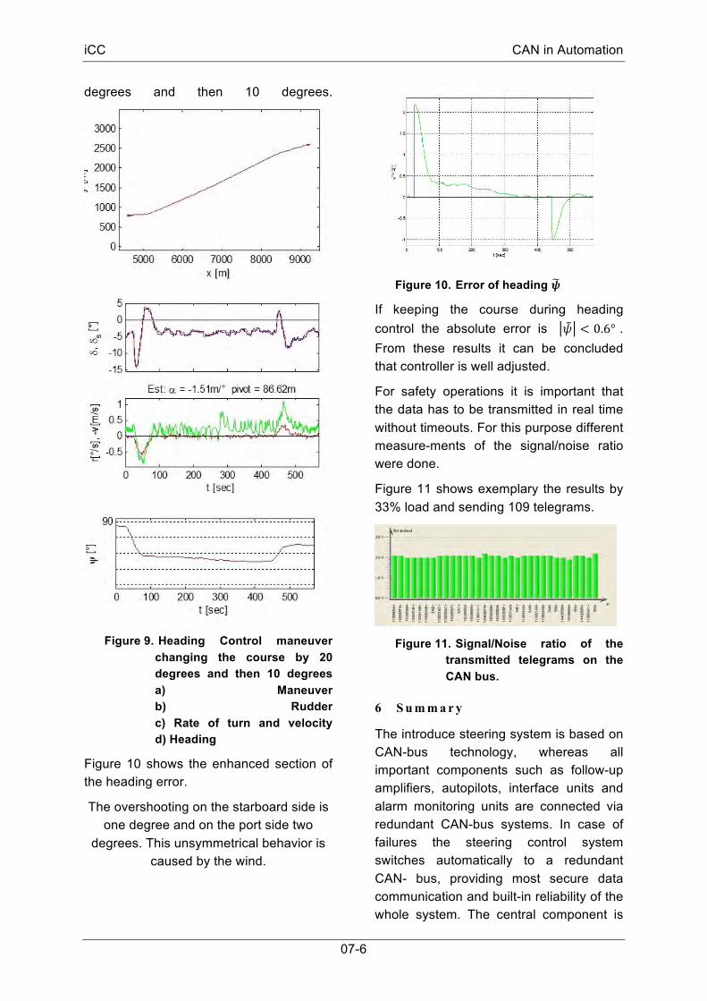
Exemplary Figure 9 shows a maneuver of the ship changing the course by 20
iCC CAN in Automation
07-6
degrees and then 10 degrees.
Figure 9. Heading Control maneuver changing the course by 20 degrees and then 10 degrees a) Maneuver b) Rudder c) Rate of turn and velocity d) Heading
Figure 10 shows the enhanced section of the heading error.
The overshooting on the starboard side is one degree and on the port side two
degrees. This unsymmetrical behavior is caused by the wind.
Figure 10. Error of heading 𝝍
If keeping the course during heading control the absolute error is 𝜓 < 0.6° . From these results it can be concluded that controller is well adjusted.
For safety operations it is important that the data has to be transmitted in real time without timeouts. For this purpose different measure-ments of the signal/noise ratio were done.
Figure 11 shows exemplary the results by 33% load and sending 109 telegrams.
Figure 11. Signal/Noise ratio of the transmitted telegrams on the CAN bus.
6 S u m m a r y
The introduce steering system is based on CAN-bus technology, whereas all important components such as follow-up amplifiers, autopilots, interface units and alarm monitoring units are connected via redundant CAN-bus systems. In case of failures the steering control system switches automatically to a redundant CAN- bus, providing most secure data communication and built-in reliability of the whole system. The central component is

iCC CAN in Automation
07-7
the autopilot. The controller was designed using the z-transform.
Simulation and practical results showed a reliable and stable behavior of the heading controller.
7 L i t e r a t u r e
[1] Thor I. Fossen, Guidance and Control of Ocean Vehicles. Chichester 1995.
[2] Berking, B., Huth, W. Handbuch Nautik. Hamburg 2010.
[3] Rios-Neta,A. Da Cruz, J.J. Stochastic Rudder Control Law for Ship Path Following Autopilots. Automatica 21(4) S. 371-384, 1985.
[4] Dörrscheidt, F., Latzel, W. Grundlagen der Regelungstechnik. 2. Aufl. Stuttgart 1993.
[5] Lawrenz, W., Obermöller, N. CAN Controller Area Network: Grundlagen, Design, Anwendungen, Testtechnik. 5. Aufl. Berlin 2011.
[6] Pfeiffer, O., Ayre, A., Keydel, C. Embedded Network with CAN and CANopen. Revised first edition. Greenfield, MA 2008.
[7] Amerongen, J. van. Adaptive steering of ships. PhD thesis, Delft University 1982.
[8] Föllinger O., Regelungstechnik – Einführung in die Methoden und ihre Anwendungen. 10. Aufl. Heidelberg, 2008.
Dr. Michael Ruff Raytheon Anschütz GmbH Zeyestr. 16-24 DE-24106 Kiel phone: +49-431-3019-630 fax: +49-431-3019-94630 [email protected] www.raytheon-anschuetz.com


![IS 8821-3 (1990): Inland vessels - steering gear, Part 3 ... · Method of shop testing [TED 18: Inland, Harbour Crafts and Fishing Vessels] IS 8821( Port 3 ) : 1990 INLAND VESSELS-STEERING](https://static.fdocuments.us/doc/165x107/5f6e4c83077e2c269f28001a/is-8821-3-1990-inland-vessels-steering-gear-part-3-method-of-shop-testing.jpg)

