Steelworker Vol. 1 -14250
246
DISTRIBUTION STATEMEN T A: Approved for public release; distributi on is unlimited. NONRESIDENT TRAINING COURSE November 1996 Steelworker, Volume 1 NAVEDTRA 14250
-
Upload
chad-vanwinkle -
Category
Documents
-
view
227 -
download
0
Transcript of Steelworker Vol. 1 -14250

8/8/2019 Steelworker Vol. 1 -14250
http://slidepdf.com/reader/full/steelworker-vol-1-14250 1/246
DISTRIBUTION STATEMENT A: Approved for public release; distribution is unlimited.
NONRESIDENT
TRAINING
COURSE November 1996
Steelworker, Volume 1
NAVEDTRA 14250

8/8/2019 Steelworker Vol. 1 -14250
http://slidepdf.com/reader/full/steelworker-vol-1-14250 2/246
DISTRIBUTION STATEMENT A: Approved for public release; distribution is unlimited.
Although the words “he,” “him,” and“his” are used sparingly in this course toenhance communication, they are notintended to be gender driven or to affront ordiscriminate against anyone.

8/8/2019 Steelworker Vol. 1 -14250
http://slidepdf.com/reader/full/steelworker-vol-1-14250 3/246
COMMANDING OFFICERNETPDTC
6490 SAUFLEY FIELD RD
PENSACOLA, FL 32509-5237
ERRATA #1 29 May 2001
Specific Instructions and Errata forNonresident Training Course
STEELWORKER, VOLUME 1, NAVEDTRA 14250
1. This errata supersedes all previous errata. No attempt has been made toissue corrections for errors in typing, punctuation, etc., that do not affectyour ability to answer the question or questions.
2. To receive credit for deleted questions, show this errata to your local
course administrator (ESO/scorer). The local course administrator is directedto correct the course and the answer key by indicating the questions deleted.
3. Assignment Booklet
Delete the following questions, and leave the corresponding spaces blankon the answer sheets:
Questions
1-60
2-13
3-16
3-17
3-18
3-47
3-48
3-50
3-52
5-2

8/8/2019 Steelworker Vol. 1 -14250
http://slidepdf.com/reader/full/steelworker-vol-1-14250 4/246

8/8/2019 Steelworker Vol. 1 -14250
http://slidepdf.com/reader/full/steelworker-vol-1-14250 5/246
i
PREFACE
By enrolling in this self-study course, you have demonstrated a desire to improve yourself and the Navy.
Remember, however, this self-study course is only one part of the total Navy training program. Practical
experience, schools, selected reading, and your desire to succeed are also necessary to successfully round
out a fully meaningful training program.
COURSE OVERVIEW: In completing this nonresident training course, you will demonstrate a
knowledge of the subject matter by correctly answering questions on the following subjects:
Properties and Uses of Metals
Basic Heat Treatment
Introduction to Welding
Gas Cutting
Gas Welding
Soldering, Brazing, Braze Welding, and Wearfacing
Shielded Metal-Arc Welding and Wearfacing
Gas Shielded-Arc Welding
THE COURSE: This self-study course is organized into subject matter areas, each containing learning
objectives to help you determine what you should learn along with text and illustrations to help you
understand the information. The subject matter reflects day-to-day requirements and experiences of
personnel in the rating or skill area. It also reflects guidance provided by Enlisted Community Managers
(ECMs) and other senior personnel, technical references, instructions, etc., and either the occupational or
naval standards, which are listed in the Manual of Navy Enlisted Manpower Personnel Classifications
and Occupational Standards, NAVPERS 18068.
THE QUESTIONS: The questions that appear in this course are designed to help you understand the
material in the text.
VALUE: In completing this course, you will improve your military and professional knowledge.
Importantly, it can also help you study for the Navy-wide advancement in rate examination. If you are
studying and discover a reference in the text to another publication for further information, look it up.
1996 Edition Prepared by
SWCS Roger Talbert, USN
and
SWC(SCW) Roger D. Keeton, USN
Published by
NAVAL EDUCATION AND TRAINING
PROFESSIONAL DEVELOPMENTAND TECHNOLOGY CENTER
NAVSUP Logistics Tracking Number
0504-LP-026-8840

8/8/2019 Steelworker Vol. 1 -14250
http://slidepdf.com/reader/full/steelworker-vol-1-14250 6/246
ii
Sailor’s Creed
“I am a United States Sailor.
I will support and defend theConstitution of the United States of
America and I will obey the ordersof those appointed over me.
I represent the fighting spirit of theNavy and those who have gonebefore me to defend freedom anddemocracy around the world.
I proudly serve my country’s Navycombat team with honor, courageand commitment.
I am committed to excellence andthe fair treatment of all.”

8/8/2019 Steelworker Vol. 1 -14250
http://slidepdf.com/reader/full/steelworker-vol-1-14250 7/246
C O N T E N T S
CHAPTER PAGE
1.
2.
3.
4.
5.
6.
7.
8.
Properties and Uses of Metal . . . . . . . . . . . . . . . . . . . . . 1-1
Basic Heat Treatment . . . . . . . . . . . . . . . . . . . . . 2-1
Introduction to Welding . . . . . . . . . . . . . . . . . . . . . . 3-1
Gas Cutting . . . . . . . . . . . . . . . . . . . . . . . . . . . .4-1
Gas Welding . . . . . . . . . . . . . . . . . . . . . . . . . . . .5-1
Soldering, Brazing, Braze Welding, and Wearfacing . . . . . . . . . 6-1
Shielded Metal-Arc Welding and Wearfacing . . . . . . . . . . . . 7-1
Gas Shielded-Arc Welding . . . . . . . . . . . . . . . . . . . 8-1
APPENDIX
I. Glossary . . . . . . . . . . . . . . . . . . . . . . . . . . . . . . . AI-1
II . References Used to Develop the TRAMAN . . . . . . . . . . . . . . . . AII-1
INDEX . . . . . . . . . . . . . . . . . . . . . . . . . . . . . . . . . . . . .INDEX-1
ii i

8/8/2019 Steelworker Vol. 1 -14250
http://slidepdf.com/reader/full/steelworker-vol-1-14250 8/246
S U M M A R Y O F
S T E E L W O R K E R , V O L U M E I
T R A I N I N G M A N U A L S
VOLUME 1
S teelworker, Volum e 1, NAVEDTRA 14250, consists of chapters on the
following subjects: Properties and Uses of Metal; Basic Heat Treatment;
Introduction to Welding; Gas Cutting; Gas Welding; Soldering, Brazing, Braze
Welding, an d Wear facing; Shielded Metal-Arc Welding a nd Wearfacing; an d Ga s
Shielded-Arc Welding.
VOLUME 2
S teelworker, Volum e 2, NAVEDTRA 14251, consists of chapters on the
following subjects: Construction Administration and Support; Sheet Metal and
Fiber Glass Duct Layout and Fabrication; Structural Steel and Pipe Layout and
Fabrication; Fiber Line; Wire Rope; Rigging and Hoisting; Concrete Construction
(Re inforc ing S tee l ) ; P re -eng ineered Bui ld ings , Towers , and Antennas ;
Pre-engineered Storage Tanks; Pontoons; and SATS matting.
iv

8/8/2019 Steelworker Vol. 1 -14250
http://slidepdf.com/reader/full/steelworker-vol-1-14250 9/246
v
INSTRUCTIONS FOR TAKING THE COURSE
ASSIGNMENTS
The text pages that you are to study are listed atthe beginning of each assignment. Study these
pages carefully before attempting to answer the
questions. Pay close attention to tables and
illustrations and read the learning objectives.
The learning objectives state what you should be
able to do after studying the material. Answering
the questions correctly helps you accomplish the
objectives.
SELECTING YOUR ANSWERS
Read each question carefully, then select the
BEST answer. You may refer freely to the text.
The answers must be the result of your own
work and decisions. You are prohibited from
referring to or copying the answers of others and
from giving answers to anyone else taking the
course.
SUBMITTING YOUR ASSIGNMENTS
To have your assignments graded, you must be
enrolled in the course with the Nonresident
Training Course Administration Branch at the
Naval Education and Training Professional
Development and Technology Center(NETPDTC). Following enrollment, there are
two ways of having your assignments graded:
(1) use the Internet to submit your assignments
as you complete them, or (2) send all the
assignments at one time by mail to NETPDTC.
Grading on the Internet: Advantages to
Internet grading are:
• you may submit your answers as soon as
you complete an assignment, and
• you get your results faster; usually by the
next working day (approximately 24 hours).
In addition to receiving grade results for each
assignment, you will receive course completion
confirmation once you have completed all the
assignments. To submit your assignment
answers via the Internet, go to:
https://courses.cnet.navy.mil
Grading by Mail: When you submit answer
sheets by mail, send all of your assignments at
one time. Do NOT submit individual answer
sheets for grading. Mail all of your assignments
in an envelope, which you either provide
yourself or obtain from your nearest Educational
Services Officer (ESO). Submit answer sheets
to:
COMMANDING OFFICER
NETPDTC N331
6490 SAUFLEY FIELD ROAD
PENSACOLA FL 32559-5000
Answer Sheets: All courses include one
“scannable” answer sheet for each assignment.
These answer sheets are preprinted with your
SSN, name, assignment number, and course
number. Explanations for completing the answersheets are on the answer sheet.
Do not use answer sheet reproductions: Use
only the original answer sheets that we
provide—reproductions will not work with ourscanning equipment and cannot be processed.
Follow the instructions for marking your
answers on the answer sheet. Be sure that blocks
1, 2, and 3 are filled in correctly. Thisinformation is necessary for your course to be
properly processed and for you to receive credit
for your work.
COMPLETION TIME
Courses must be completed within 12 months
from the date of enrollment. This includes time
required to resubmit failed assignments.

8/8/2019 Steelworker Vol. 1 -14250
http://slidepdf.com/reader/full/steelworker-vol-1-14250 10/246
vi
PASS/FAIL ASSIGNMENT PROCEDURES
If your overall course score is 3.2 or higher, you
will pass the course and will not be required to
resubmit assignments. Once your assignmentshave been graded you will receive course
completion confirmation.
If you receive less than a 3.2 on any assignment
and your overall course score is below 3.2, youwill be given the opportunity to resubmit failed
assignments. You may resubmit failed
assignments only once. Internet students will
receive notification when they have failed an
assignment--they may then resubmit failedassignments on the web site. Internet students
may view and print results for failed
assignments from the web site. Students who
submit by mail will receive a failing result letterand a new answer sheet for resubmission of eachfailed assignment.
COMPLETION CONFIRMATION
After successfully completing this course, youwill receive a letter of completion.
ERRATA
Errata are used to correct minor errors or delete
obsolete information in a course. Errata mayalso be used to provide instructions to the
student. If a course has an errata, it will be
included as the first page(s) after the front cover.
Errata for all courses can be accessed andviewed/downloaded at:
https://www.advancement.cnet.navy.mil
STUDENT FEEDBACK QUESTIONS
We value your suggestions, questions, and
criticisms on our courses. If you would like tocommunicate with us regarding this course, we
encourage you, if possible, to use e-mail. If you
write or fax, please use a copy of the Student
Comment form that follows this page.
For subject matter questions:
E-mail: [email protected]
Phone: Comm: (850) 452-1001, Ext. 1826
DSN: 922-1001, Ext. 1826FAX: (850) 452-1370
(Do not fax answer sheets.)Address: COMMANDING OFFICER
NETPDTC N314
6490 SAUFLEY FIELD ROADPENSACOLA FL 32509-5237
For enrollment, shipping, grading, or
completion letter questions
E-mail: [email protected]
Phone: Toll Free: 877-264-8583
Comm: (850) 452-1511/1181/1859
DSN: 922-1511/1181/1859FAX: (850) 452-1370(Do not fax answer sheets.)
Address: COMMANDING OFFICER
NETPDTC N331
6490 SAUFLEY FIELD ROAD
PENSACOLA FL 32559-5000
NAVAL RESERVE RETIREMENT CREDIT
If you are a member of the Naval Reserve,
you may earn retirement points for successfully
completing this course, if authorized undercurrent directives governing retirement of Naval
Reserve personnel. For Naval Reserve retire-
ment, this course is evaluated at 9 points. (Refer
to Administrative Procedures for Naval
Reservists on Inactive Duty, BUPERSINST
1001.39, for more information about retirement
points.)

8/8/2019 Steelworker Vol. 1 -14250
http://slidepdf.com/reader/full/steelworker-vol-1-14250 11/246
vii
Student Comments
Course Title: Steelworker, Volume 1
NAVEDTRA: 14250 Date:
We need some information about you:
Rate/Rank and Name: SSN: Command/Unit
Street Address: City: State/FPO: Zip
Your comments, suggestions, etc.:
Privacy Act Statement: Under authority of Title 5, USC 301, information regarding your military status is
requested in processing your comments and in preparing a reply. This information will not be divulged without
written authorization to anyone other than those within DOD for official use in determining performance.
NETPDTC 1550/41 (Rev 4-00

8/8/2019 Steelworker Vol. 1 -14250
http://slidepdf.com/reader/full/steelworker-vol-1-14250 12/246

8/8/2019 Steelworker Vol. 1 -14250
http://slidepdf.com/reader/full/steelworker-vol-1-14250 13/246
C H A PTER 1
P R O P E R T I E S A N D U S E S O F M E T A L
In the seabees, Steelworkers are the resident
experts on the properties and uses of metal. We lay
airfields, erect towers and storage tanks, assemble
pontoon cau seways, and constr uct buildings. We use
our expertise to repair metal items, resurface worn
machinery parts, and fabricate all types of metal
objects. To accomplish these tasks proficiently, one
mu st possess a sound working k nowledge of var ious
metals and their properties. As we learn their different
properties and characteristics, we can then select the
right type of metal and use the proper method to
complete the job. Steelworkers primarily work with
iron and steel; however, we also must become familiar
with the nonferrous metals coming into use more and
more each day. As Steelworkers, we must be able to
identify various metals and to associate their
individual properties with their proper application or
use.
The primary objective of this chapter is to present
a detailed explanation of some of the properties of
different metals and to provide instruction on using
simple tests in establishing their identity.
M E T A L P R O P E R T IE S
Ther e is n o simple definition of metal; however,
an y chemical element ha ving “meta llic properties” is
classed as a meta l. “Metallic properties” ar e defined
as luster, good thermal and electrical conductivity, and
the capabil i ty of being permanently shaped or
deformed at room temperature. Chemical elements
lacking th ese properties a re classed as n onmeta ls. A
few elements, known as metalloids, sometimes behave
like a metal and at other times like a nonmetal. Some
examples of metalloids are as follows: carbon,
phosphorus, silicon, and sulfur.
Although Steelworkers seldom work with pure
metals, we must be knowledgeable of their properties
becau se th e alloys we work with ar e combina tions of
pure metals. Some of the pure metals discussed in this
chapter are the base metals in these alloys. This is true
of iron, aluminum, and magnesium. Other metals
discussed ar e th e alloying elements present in sma ll
quantities but important in their effect. Among these are
chromium, molybdenum, titanium, and manganese.
An “alloy” is defined as a substance having metallic
properties that is composed of two or more elements.
The elements used as alloying substances are usually
metals or metalloids. The properties of an alloy differ
from the properties of the pure metals or metalloids that
make up the alloy and this difference is what creates the
usefulness of alloys. By combining metals and metal-
loids, manufacturers can develop alloys that have the
particular properties required for a given use.
Table 1-1 is a list of various elements and their
symbols that compose metallic materials.
Tab le 1-1.—Symb ols of Base Meta l s and Al loying Elem ent s
1-1

8/8/2019 Steelworker Vol. 1 -14250
http://slidepdf.com/reader/full/steelworker-vol-1-14250 14/246
Figure 1-1.—Stress appl ied to a mater ia I .
Very ra rely do Steelworker s work with elements
in th eir pure st ate. We primarily work with alloys and h ave
to understand their characteristics. The characteristics
of elements and alloys are explained in terms of
physical , chemical , e lec t r ica l , and mechanical
properties. Physical properties relate to color, density,
weight, and heat conductivity. Chemical properties
involve the behavior of the metal when placed in
contact with the atmosphere, salt water, or other
substances. Electrical properties encompass theelectrical conductivity, resistance, and magnetic
qualities of the metal. The mechanical properties
relate to load-carrying abil i ty, wear resistance,
har dness, and elasticity.
When selecting stock for a job, your main
concern is the mechanical properties of the metal.
The various properties of metals and alloys were
determined in the laboratories of manufacturers and
by various societ ies interested in metallurgical
development. Charts presenting the properties of a
particular metal or alloy are available in many
commercia l ly publ ished reference books . The
charts provide information on the melting point,
tensile strength, electrical conductivity, magnetic
properties, and other properties of a particular metal
or alloy. Simple tests can be condu cted to determ ine
some of the properties of a metal; however, we
normally use a metal test only as an aid for
identifying apiece of stock. Some of these methods
of testing are discussed later in this chapter.
MECHANICAL PROPERTIES
Strength, hardness, toughness, elasticity, plasticity,
brit t leness, and ducti l i ty and malleabil i ty are
mechanical properties used as mea sur ement s of how
metals behave under a load. These properties are
described in t erms of th e types of force or st ress t ha t
the metal must withstand and how these are resisted.
Common types of stress are compression, tension,
shea r, torsion, impact, 1-2 or a combinat ion of these
stresses, such as fatigue. (See fig. 1-1.)
Compression stresses develop within a material
when forces compress or crush the material. A column
that supports an overhead beam is in compression, and
the internal stresses that develop within the column are
compression.
Tension (or tensile) stresses develop when amat erial is su bject to a pu lling load; for exam ple, when
using a wire rope to lift a load or when u sing it as a
guy to anchor an antenna. “Tensile strength” is defined
as resistance to longitudinal stress or pull and can be
measured in pounds per square inch of cross section.
Shearing stresses occur within a material when
external forces are applied along parallel lines in
opposite directions. Shearing forces can separate
material by sliding part of it in one direction and the
rest in the opposite direction.
Some materials are equally strong in compression,tension, and shear. However, many materials show
marked differences; for example, cured concrete has a
maximum strength of 2,000 psi in compression, but
only 400 psi in tension. Carbon steel has a maximum
strength of 56,000 psi in tension and compression but
a maximum shear strength of only 42,000 psi;
therefore, when dealing with maximum strength, you
should always state the type of loading.
A material that is stressed repeatedly usually fails
at a point considerably below its maximum strength in
tension, compression, or shear. For example, a thin
steel rod can be broken by hand by bending it ba ck and
forth several times in the same place; however, if the
same force is applied in a stea dy motion (not bent back
and forth), the rod cannot be broken. The tendency of
a ma terial to fail after r epeated bending at the sa me
point is known as fatigue.
1-2

8/8/2019 Steelworker Vol. 1 -14250
http://slidepdf.com/reader/full/steelworker-vol-1-14250 15/246
Table 1-2.—Mechanical Properties of Metals/Alloys
St reng th Rockwell “C” number. On nonferrous metals, that are
Strength is the property that enables a metal to resist
deformation under load. The ultimate strength is the
maximum strain a material can withstand. Tensile
strength is a measu rement of the resistance to being
pulled apart when placed in a tension load.
Fat igue str ength is th e ability of mat erial to resist
various kinds of rapidly changing stresses and is ex-
pressed by the ma gnitude of alterna ting stress for a
specified number of cycles.
Impact str ength is t he ability of a m etal to resist
suddenly applied loads and is measured in foot-pounds
of force.
Hardness
Hardness is the property of a material to resist
permanent indentation. Because t here ar e several meth -
ods of measuring hardness, the hardness of a material is
always specified in terms of the particular test that was
used to mea sur e th is propert y. Rockwell, Vickers, or
Brinell are some of the meth ods of testing. Of these tests,
Rockwell is the one most frequently used. The basic
principle used in the Rockwell testis that a hard material
can penetrate a softer one. We then measure the amount
of penet ra tion an d compa re it t o a scale. For ferr ous
metals, which are usu ally harder tha n n onferrous metals,
a diamond tip is used and the hardness is indicated by a
softer, a metal ball is used and the hardness is indicated
by a Rockwell “B” number. To get an idea of the
property of hardness, compare lead and steel. Lead can
be scratched with a pointed wooden stick but steel
cannot because it is h arder t han lead.
A full explanation of the various methods used to
determine th e har dness of a m ater ial is available in
commercial books or books located in your base library.
Tou gh n es s
Toughness is the property that enables a material to
withstand shock and to be deformed without rupturing.
Toughness may be considered as a combination of
strength a nd plasticity. Table 1-2 shows the order of
some of the more common materials for toughness as
well as other properties.
E l a s t i c i t y
When a material has a load applied to it, the load
causes the material to deform. Elasticity is the ability of
a material to return to its original shape after the load is
removed. Theoretically, the elastic limit of a material is
the limit t o which a mat erial can be loaded an d still
recover its original shape after the load is removed.
1-3

8/8/2019 Steelworker Vol. 1 -14250
http://slidepdf.com/reader/full/steelworker-vol-1-14250 16/246
P last ic i ty
Plasticity is the ability of a material to deform
permanent ly without breaking or ruptu ring. This prop-
ert y is th e opposite of strengt h. By careful alloying of
meta ls, the combination of plasticity an d str ength is u sed
to manufacture large structural members. For example,
should a m ember of a br idge stru cture become over-
loaded, plasticity allows the overloaded member to flow
allowing the distr ibution of the load t o other part s of the
bridge structure.
Br i t t l e n e ss
Brittleness is the opposite of the property of plastic-
ity. A brittle metal is one that breaks or shatters before
it deforms. White cast iron and glass are good examples
of brittle material. Generally, brittle metals are high in
compressive strength but low in tensile strength. As an
example, you would not choose cast iron for fabricating
support beams in a bridge.
Ducti l i ty and Malleabil i ty
Ductility is the property tha t ena bles a material t o
str etch, bend, or t wist without cracking or br eaking. This
property mak es it possible for a mat erial to be drawn out
into a thin wire. In comparison, malleability is the
property that enables a material to deform by compres-
sive forces without developing defects. A malleable
material is one that can be stamped, hammered, forged,
pressed, or rolled into thin sheets.
CORROSION RESISTANCE
Corrosion resistance, although not a mechanical
property, is important in the discussion of metals. Cor-
rosion resistance is the property of a metal that gives it
the ability to withstand attacks from atmospheric,
chemical, or electrochemical conditions. Corrosion,
sometimes called oxidation, is illustrated by the rusting
of iron.
Table 1-2 lists four mechanical properties and the
corrosion resistance of various metals or alloys. The first
metal or alloy in each column exhibits the best charac-
teristics of that property. The last metal or alloy in each
column exhibits the least. In the column labeled “Tough-
ness,” note that iron is not as tough as copper or nickel;
however, it is tougher than magnesium, zinc, and alumi-
num. In the column labeled “Ductility,” iron exhibits a
reasonable a mount of ductility; however, in the columns
labeled “Malleability” and “Brittleness,” it is last.
1-4
METAL TYP ES
The metals that Steelworkers work with are divided
into two general classifications: ferrous and nonferrous.
Ferr ous metals a re t hose composed prima rily of iron a nd
iron alloys. Nonferrous metals are those composed pri-
mar ily of some element or element s other t ha n iron.
Nonferrous metals or alloys sometimes contain a small
amount of iron as a n alloying element or as an impurit y.
FER ROUS METALS
Ferrous metals include all forms of iron and steel
alloys. A few examples include wrought iron, cast iron,
carbon steels, alloy steels, and tool steels. Ferrous met-
als a re ir on-base a lloys with small per centa ges of carbon
and other elements added to achieve desirable proper-
ties. Normally, ferrous metals are magnetic and nonfer-
rous metals are nonmagnetic.
Iron
Pur e iron ra rely exists outside of the laborat ory. Ironis produced by reducing iron ore to pig iron through the
use of a blast furnace. From pig iron many other types
of iron and steel are produced by the addition or deletion
of carbon and alloys. The following paragraphs discuss
the different types of iron and steel that can be made
from iron ore.
P IG IRON.— Pig iron is composed of about 93%
iron, from 3% to 5% carbon, and various a mount s of
other elements. Pig iron is comparatively weak and
brittle; therefore, it has a limited use and approximately
ninety percent produced is refined to produce steel.
Cast-iron pipe and some fittings and valves are manu-
factu red from pig iron.
WROUGH T IRON.— Wrought iron is made from
pig iron with some slag mixed in during manufacture.
Almost pur e iron, the presence of slag enables wrought
iron to r esist corr osion an d oxidat ion. The chemical
analyses of wrought iron and mild steel are just about
the same. The difference comes from the properties
controlled during the manufacturing process. Wrought
iron can be gas and arc welded, machined, plated, and
easily formed; however, it ha s a low hardn ess an d a
low-fatigue strength.
CAST IRON.— Cast iron is any iron cont aining
greater than 2% carbon alloy. Cast iron has a high-com-
pressive strength and good wear resistance; however, it
lacks ductility, malleability, and impact strength. Alloy-
ing it with nickel, chromium, molybdenum, silicon, or
vanadium improves toughness, tensile strength, a nd

8/8/2019 Steelworker Vol. 1 -14250
http://slidepdf.com/reader/full/steelworker-vol-1-14250 17/246
hardness. A malleable cast iron is produced through a easily as the low-carbon steels. They are used for crane
prolonged annealing process. hooks, axles, shaft s, set screws, and so on.
INGOT IRON.— Ingot iron is a commercially pure
iron (99.85% iron) that is easily formed and possesses
good ductility an d corr osion resist an ce. The chem ical
an alysis and pr operties of this iron and t he lowest carbon
steel are practically the same. The lowest carbon steel,
known as dead-soft, has about 0.06% more carbon than
ingot iron. In iron the carbon content is considered animpur ity an d in steel it is consider ed an alloying ele-
ment. The primary use for ingot iron is for galvanized
and enameled sheet.
S t e e l
Of all the different metals and materials that we use
in our trade, steel is by far the most important. When
steel wa s developed, it revolutionized the American iron
industry. With it came skyscrapers, stronger and longer
bridges, and r ailroad t racks th at did not collapse. Steelis manufactured from pig iron by decreasing the amount
of carbon and other impurities and adding specific
amounts of alloying elements.
Do not confuse steel with the two general classes of
iron: cast iron (greater than 2% carbon) and pure iron
(less than 0.15% carbon). In steel manufacturing, con-
trolled amounts of alloying elements are added during
th e molten s ta ge to produce the desir ed composition.
The composition of a steel is determined by its applica-
tion and the specifications that were developed by the
following: American Society for Testing and Materials(ASTM), the American Society of Mechanical Engi-
neer s (ASME), th e Society of Aut omotive E ngineer s
(SAE), and the American Iron an d Steel Inst itute (AISI).
Carbon steel is a term applied to a broad range of
steel that falls between the commercially pure ingot iron
and the cast irons. This ra nge of carbon steel ma y be
classified into four groups:
HIGH-CARBON STEEL/VERY HIGH-CAR-
BON STEE L.— Steel in these classes respond well to
heat treat ment and can be welded. When welding, spe-
cial electrodes must be used along with preheating and
stress-relieving procedures to prevent cracks in the weld
areas. These steels are used for dies, cutting tools, mill
tools, railroad car wheels, chisels, knives, and so on.
L O W - A L L O Y , H I G H - S T R E N G T H , T E M -
P ER ED STR U C TUR AL STEE L.— A special low-
carbon steel, containing specific small amounts of
alloying elements, that is quenched and tempered to get
a yield strength of greater than 50,000 psi and tensile
str engths of 70,000 to 120,000 psi. Stru ctural members
made from these high-strength steels may have smaller
cross-sectional areas tha n common st ructur al steels
and still have equal or greater strength. Additionally,
these steels are normally more corrosion- and abrasion-
resista nt . High-str ength s teels ar e covered by ASTMspecifications.
N O TE: This type of steel is much tougher than
low-carbon steels. Shea ring m achines for this t ype of
steel must have twice the capacity than that required for
low-carbon steels.
STAINLESS STEE L.— This type of steel is clas-
sified by the American Iron and Steel Institute (AISI)
into two general series named the 200-300 series and
400 series. Each series includes several types of steel
with different characteristics.
The 200-300 series of stainless st eel is known as
AUSTENITIC. This type of steel is very tough and
ductile in the as-welded condition; therefore, it is ideal
for welding an d requires no ann ealing under norma l
atmospheric conditions. The most well-known types of
steel in this series ar e the 302 an d 304. They are com-
monly called 18-8 because th ey ar e composed of 18%
chromium and 8% nickel. The chromium nickel steelsLow-Carbon Steel . . . . . . . . 0.05% to 0.30% carbon are the most widely used and are normally nonmagnetic.
Medium -Carbon St eel . . . . . . 0.30% to 0.45% carbonThe 400 s eries of steel is subdivided accordin g to
High-Car bon St eel . . . . . . . . 0.45% to 0.75% carbon their crystalline structure into two general groups. One
Very High-Carbon Steel . . . . . 0.75% to 1.70% carbon group is kn own a s FE RRITIC CHROMIUM and t he
other group as MARTENSITIC CHROMIUM.
LOW-CARBON ST EE L.— Steel in t his classifi-F e r r i t ic C h r o m i u m .—This type of steel contains
cation is tough an d ductile, easily ma chined, formed,12% to 27% chromium and 0.08% to 0.20% carbon.
and welded. It does not respond to any form of heatThese alloys are the straight chromium grades of stain-
treating, except case hardening.less steel since they contain no nickel. They are nonhar-
MEDIUM-CARBON STEEL.— These steels are denable by heat treatment and are normally used in the
strong an d har d but cann ot be welded or worked a s annealed or soft condition. Ferritic steels are magnetic
1-5

8/8/2019 Steelworker Vol. 1 -14250
http://slidepdf.com/reader/full/steelworker-vol-1-14250 18/246

8/8/2019 Steelworker Vol. 1 -14250
http://slidepdf.com/reader/full/steelworker-vol-1-14250 19/246
True Brass sinks or pr otect bench t ops where a lar ge amount of acid
is used. Lead-lined pipes are used in systems that carry
This is an alloy of copper and zinc. Additional corr osive chemicals. F requent ly, lead is u sed in alloyed
elements, such as aluminum, lead, tin, iron, manganese, form to increase its low-tensile strength. Alloyed with
or phosphorus, are added to give the alloy specific tin, lead produces a soft solder. When added to metal
properties. Naval rolled brass (Tobin bronze) contains alloys, lead improves their machinability.
about 60% copper, 39% zinc, and 0.75% tin. This brass
is highly corrosion-resistant and is practically impurity
free. CAUTION
Brass sheets and strips are available in several
grades: soft, 1/4 har d, 1/2 har d, full har d, and spr ing When working with lead, you m ust take
grades . Hardness is crea ted by the process of cold rol l- proper precaut ions because the dust , fumes, or
ing. All grades of bra ss can be softened by ann ealing at vapors from it are highly poisonous.
a temperature of 550°F to 600°F then allowing it to cool
by itself without quenching. Overheating can destroy
the zinc in the alloy. Zinc
Bronze
Bronze is a combination of 84% copper and 16% tin
and was the best metal available before steel-makingtechniques were developed. Many complex bronze al-
loys, containing such elements as zinc, lead, iron, alu-
minum, silicon, and phosphorus, are now available.
Today, the name bronze is applied to any copper-based
alloy that looks like bronze. In many cases, there is no
real distinction between the composition of bronze and
that of brass.
Copper-Nickel Alloys
Nickel is used in these alloys to make them strong,
tough, and resistant to wear and corrosion. Because of their high resistance to corrosion, copper nickel alloys,
containing 70% copper and 30% nickel or 90% copper
and 10% nickel, are used for saltwater piping systems.
Small storage tanks and hot-water reservoirs are con-
You often see zinc used on iron or steel in the form
of a protective coating called galvanizing. Zinc is also
used in soldering fluxes, die castings, and as an alloy in
making brass a nd bronze.
T in
Tin has m any important uses as a n alloy. It can be
alloyed with lea d to produce softer solders a nd with
copper to produce bronze. Tin-based alloys have a high
resistance to corrosion, low-fatigue strength, and a com-
pressive strength that accommodates light or medium
loads. Tin, like lead, has a good resistance to corrosion
and has the added advantage of not being poisonous;
however, when subjected to extremely low temper a-
tures, it has a tendency to decompose.
Aluminum
str utt ed of a copper-nickel alloy tha t is available in sheetThis metal is easy to work with and has a good
form. Copper-nickel alloys should be joined by metal-appearance. Aluminum is light in weight and has a high
arc welding or by brazing.strength per unit weight. A disadvantage is that the
Leadtensile strength is only one third of that of iron and one
fifth of that of annealed mild steel.
A heavy metal tha t weighs a bout 710 pounds per
cubic foot. In spite of its weight, lead is soft and malle-able and is a vailable in pig and sheet form . In sheet form ,
it is rolled upon a rod so the user can unroll it and cut
off the desired amount. The surface of lead is grayish in
color; however, after scratching or scraping it, you can
see that the actual color of the metal is white. Because
it is soft, lead is used as backing mat erial when pun ching
holes with a hollow punch or when forming shapes by
hammering copper sheets. Sheet lead is also used to line
Aluminum alloys usually contain at least 90% alu-
minu m. The addit ion of silicon, ma gnesium, copper,nickel, or manganese can raise the strength of the alloy
to that of mild steel. Aluminum, in its pure state, is soft
and has a strong affinity for gases. The use of alloying
elements is used to overcome these disadvantages; how-
ever, the alloys, unlike th e pur e alumin um , corrodes
unless given a protective coating. Threaded parts made
of aluminum alloy should be coated with an antiseize
compound to prevent sticking caused by corrosion.
1-7

8/8/2019 Steelworker Vol. 1 -14250
http://slidepdf.com/reader/full/steelworker-vol-1-14250 20/246
Table 1-3.—Sur face Colors of Some Comm on Meta ls
Dura lum in Monel
One of the first of the strong structural aluminum
alloys developed is called Duralumin. With the devel-
opment of a variety of different wrought-aluminum
alloys, a nu mbering system was a dopted. The digits
indicate the major alloying element and the cold-worked
or heat-treated condition of the metal. The alloy, origi-
nally called Duralumin, is now classified in the metal
working industries as 2017-T. The letter T indicates that
the metal is heat-treated.
Alclad
This is a protective covering that consists of a thin
sheet of pure a luminu m r olled ont o the sur face of an
aluminum alloy during manufacture. Zinc chromate is
a pr otective covering tha t can be applied to an aluminu m
surface as n eeded. Zinc chromate is also used as a primer
on steel surfaces for a protective coating.
Monel is an alloy in which nickel is the major
element. It contains from 64% to 68% nickel, about 30%
copper, and small percentages of iron, manganese, and
cobalt. Monel is har der an d str onger th an either nickel
or copper a nd h as high ductility. It r esembles st ainless
steel in appearance and has many of its qualities. The
strength, combined with a high resistance to corrosion,
make Monel an a cceptable substitut e for steel in systems
where corr osion resistan ce is th e prima ry concern. Nuts,
bolts, screws, and various fittings are made of Monel.
This alloy can be worked cold and can be forged and
welded. If worked in t he temp erat ur e ran ge between1200°F and 1600°F, it becomes “hot short” or brittle.
K-Monel
This is a special type of alloy developed for greater
strength a nd har dness than Monel. In strength, it is
1-8

8/8/2019 Steelworker Vol. 1 -14250
http://slidepdf.com/reader/full/steelworker-vol-1-14250 21/246
comparable to heat-treated steel. K-monel is used for
instrument parts t hat must r esist corrosion.
Incone l
This high-nickel alloy is often used in the exhaust
systems of aircraft engines. Inconel is composed of
78.5% nickel, 14% chromium, 6.5% iron, and 1% of
other elements. It offers good resistance to corrosion and
retains its strength a t h igh-operating temperatures.
METAL IDENTIFICATION
Many methods are used to identify a piece of metal.
Identification is necessary when selecting a metal for
use in fabrication or in determining its weldability.
Some common methods used for field identification are
surface appearance, spark test, chip test, and the use of
a magnet.
SURFACE APP EARANCE
Sometimes it is possible to identify metals by their
surface appearance. Table 1-3 indicates the surface col-
ors of some of th e more common met als. Referr ing to
the table, you can see that the outside appearance of a
metal helps to identify and classify metal. Newly frac-
tured or freshly filed surfaces offer additional clues.
A surface examination does not always provide
enough information for identification but should give usenough information to place the metal into a class. The
color of th e meta l and t he dist inctive mark s left from
manufacturing help in determining the identity of the
metal. Cast iron and malleable iron usually show evi-
dence of the sand mold. Low-carbon steel often shows
forging marks, and high-carbon steel shows either forg-
ing or rolling marks. Feeling the surface may provide
another clue. Stainless steel is slightly rough in the
unfinished state, and the surfaces of wrought iron, cop-
per, brass, bronze, nickel, and Monel are smooth. Lead
also is smooth but has a velvety appearance.
When the surface appearance of a metal does not
give en ough in form at ion to a llow positive identifica-
tion, other identification tests become necessary. Some
of these tests are complicated and require equipment we
do not usually have; however, other tests are fairly
simple and reliable when done by a skilled person. Three
of these tests areas follows: the spark test, the chip test,
and t he magnetic tests.
Figure 1-2.—Terms used in spark tes t ing.
SP ARK TEST
The spark test is m ade by holding a sam ple of the
material against an abrasive wheel. By visually inspect-
ing the spark stream, an experienced metalworker canidentify the metals with considerable accuracy. This test
is fast, economical, convenient, and easily accom-
plished, and there is no requirement for special equip-
ment . We can use t his test for ident ifying metal salvaged
from scrap. Identification of scrap is particularly impor-
tan t wh en selecting ma terial for cast iron or cast steel
hea t t rea tment .
When you h old a piece of iron or st eel in cont act
with a high-speed abrasive wheel, small particles of the
meta l are t orn loose so rapidly tha t t hey become red-hot.
As these glowing bits of meta l leave the wh eel, they
follow a p at h (tr ajectory) called th e carr ier line. This
carrier line is easily followed with the eye, especial] y
when observed against a dark background.
The spar ks given off, or t he lack of spar ks, aid in t he
identification of the metal. The length of the spark
stream, the color, and the form of the sparks are features
you should look for. Figure 1-2 illustrates the terms used
in referrin g to var ious ba sic spar k form s produced in
spark testing.
Steels having the same carbon content but differing
alloying elements are difficult to identify because thealloying elements affect the carrier lines, the bursts, or
the forms of char acteristic bursts in th e spark pictur e,
The effect of the alloying element may slow or acceler-
ate t he carbon spar k or make t he carrier line lighter or
darker in color. Molybdenum, for example, appears as
a detached, orange-colored spearhead on the end of the
carrier line. Nickel appears to suppress the effect of the
carbon burst ; however, the n ickel spar k can be identified
1-9

8/8/2019 Steelworker Vol. 1 -14250
http://slidepdf.com/reader/full/steelworker-vol-1-14250 22/246
by tiny blocks of brilliant white light. Silicon suppresses
the carbon burst even more than nickel. When silicon is
present, the carrier line usually ends abruptly in a white
flash of light.
Spark testing may be done with either a portable or
stationary grinder. In either case, the speed on the outer
rim of the wheel should not be less than 4,500 feet per
minu te. The abras ive wheel should be rat her coar se,
very hard, and kept clean t o produce a true spa rk
To conduct a spark test on an abra sive wheel, hold
the piece of metal on the wheel in a position that allows
the spa rk strea m t o cross your line of vision. By trial a nd
error, you soon discover what pressure is needed to get
a st ream of the pr oper length without r educing the speed
of the grind er. Excessive pressur e increases t he tem -
perature of the spark stream. This, in turn, increases the
temperature of the burst and gives the appearance of a
higher carbon content than actually is present. When
making th e test, watch a point a bout one th ird of the
distance from the tail end of the spark stream. Watch
only those sparks that cross your line of vision and try
to forma m enta l image of the individual spar k. Fix this
spark image in your mind and then examine the whole
spark picture.
While on the subject of abrasive wheels, it is a good
idea to discuss some of the safety precautions associated
with this tool.
l Never use an a brasive wheel that is cra cked or
out of balance because the vibration causes the wheel to
shatt er. When an abrasive wheel shatters, i t can be
disastrous for personnel standing in line with the wheel.
l Always check the wheel for secure mounting and
cracks before putting it to use. When you install a new
wheel on a grinder, be sure t ha t it is t he corr ect size.
Remember, as you increase th e wheel radius, the periph-
eral speed at t he rim a lso increases, even though th e
driving motor rpm rema ins th e same. Thus, if you sh ould
use an oversized wheel, there is a distinct danger the
peripheral speed (and consequent centrifugal force) can
become so great that the wheel may fly apart. Use
wheels that are designed for a specific rpm. Guards are
placed on grinders as protection in case a wheel should
shatter.
. Never use a grinder when the guards have been
removed. When tur ning the grinder on, you sh ould sta nd
to one side. This places you out of line with the wheel
in case the wheel should burst.
1-10
l Never overload a grinder or put sideways pr es-
sur e against t he wheel, unless it is expressly built to
withstand such use.
l Always wear appropriate safety goggles or a face
shield while using the grinder. Ensure that the tool rest
(the device th at helps th e opera tor hold the work) is
adjusted to the minimum clearance for the wheel. Move
the work a cross t he entir e face of the wh eel to eliminate
grooving and to minimize wheel dressing. Doing this
prolongs the life of the wheel.
l Keep your fingers clear of the abrasive surface,
and do not allow rags or clothing to become entangled
in the wheel.
l Do not wear gloves while using an abrasive
wheel.
l Never hold metal with tongs while grinding.
. Never grind nonferrous metals on a wheel in-
tended for ferrous metals because such misuse clogs the
pores of the abr asive mat erial. This buildup of meta l
may cause it t o become un balanced and fly apart.
c Grinding wheels require frequent recondition-
ing. Dressing is the term used to describe the process of
cleaning t he periphery. This cleaning br eaks a way dull
abrasive grains and smooths the surface, removing all
the grooves. The wheel dresser shown in figure 1-3 is
used for dressing grinding wheels on bench a nd pedestal
grinders. For more information on grinding wheels, you
should consult chapter 5 of NAVEDTRA 10085-B2
(Tools and Their Uses).
Referring now to figure 1-4, notice that in low-carbon steel (view A), the spark stream is about 70
inches long and the volume is moderately large. In
high-carbon steel (view B), the stream is shorter (about
55 inches) and th e volume larger. The few sparklers t hat
may occur at any place in low-carbon steel are forked,
Figure 1-3.—Using a gr inding wheel dresser .

8/8/2019 Steelworker Vol. 1 -14250
http://slidepdf.com/reader/full/steelworker-vol-1-14250 23/246
Figure 1-4.—S park pa t t e rn s fo rm ed by com m on m e ta l s .
1-11

8/8/2019 Steelworker Vol. 1 -14250
http://slidepdf.com/reader/full/steelworker-vol-1-14250 24/246
Table 1-4.—Metal Ident if icat ion by Chip Test
and in high-carbon steel, they are small and repeating. these metals must be distinguished from each other by
Both metals produce a spark stream white in color.
Gray cast iron (view C) produces a stream of sparks
about 25 inches in length. The sparklers are small and
repeating, and their volume is rather small. Part of the
stream near the wheel is red, and the outer portion is
straw-colored.
Monel and nickel (view D) form almost identical
spark streams. The sparks are small in volume and
orange in color. The sparks form wavy streaks with no
sparklers. Because of the similarity of the spark picture,
some other method.
Sta inless steel (view E) produces a spar k str eam
about 50 inches in length, moderate volume, and withfew sparklers. The sparklers are forked. The stream next
to the wheel is straw-colored, and at the end, it is white.
The wrought -iron spa rk t est (view F) produces a
spark str eam about 65 inches in length. The stream ha s
a large volume with few sparklers. The sparks appear
near the end of the stream and a re forked. The stream
next t o the wheel is stra w-colored, and the out er end of
the stream is a brighter r ed.
1-12

8/8/2019 Steelworker Vol. 1 -14250
http://slidepdf.com/reader/full/steelworker-vol-1-14250 25/246
One way to become proficient in spark testing fer-
rous metals is to gather an assortment of samples of
known metals and test them. Make all of the samples
about the same size and shape so their identities are not
revealed simply by the size or shape. Number each
sample and prepare a list of names and corresponding
numbers. Then, without looking at the number of the
sample, spark test one sam ple at a time, calling out its
name to someone assigned to check it against the names
and numbers on the list. Repeating this process gives
you some of the exper ience you need to become pr ofi-
cient in identifying individual samples.
CHIP TEST
from small, broken fragments to a continuous strip. The
chip may have smooth, sharp edges; it maybe coarse-
grained or fine-grained; or it may have sawlike edges.
The size of the chip is importa nt in identifying the m etal.
The ease with which the chipping can be accomplished
should also be considered. The information given in
ta ble 1-4 can help you ident ify various meta ls by th e
chip test.
MAGNETIC TE ST
The use of a m agnet is an other meth od used to aid
in the general identification of metals. Remember that
ferrous met als, being iron-based alloys, norma lly ar e
Another simple test used to identify an unk nown
piece of metal is the chip test. The chip testis made by
removing a small amount of material from the test piece
with a sharp, cold chisel. The material removed varies
magnetic, and nonferrous metals are nonmagnetic. This
test is not 100-percent accurate because some stainless
steels are nonma gnetic. In th is instance, there is no
substitute for experience.
1-13

8/8/2019 Steelworker Vol. 1 -14250
http://slidepdf.com/reader/full/steelworker-vol-1-14250 26/246

8/8/2019 Steelworker Vol. 1 -14250
http://slidepdf.com/reader/full/steelworker-vol-1-14250 27/246
C H A P T E R 2
BASIC HEAT TREATMENT
As Steelworkers, we are interested in the heat treat-
ment of metals, because we have to know what effects
the heat produced by welding or cutting has on metal.We also need to know the methods used to restore metal
to its original condition. The process of heat treating is
the method by which metals are heated and cooled in a
series of specific operations that never allow the metal
to reach the molten state. The purpose of heat treating is
to make a metal more useful by changing or restoring
its mechanical properties. Through heat treating, we can
make a metal harder, stronger, and more resistant to
impact. Also, heat treating can make a metal softer and
more ductile. The one disadvantage is that no heat-treat-
ing procedure can produce all of these characteristics in
one operat ion. Some properties are improved at theexpense of others; for example, hardening a metal may
make it brittle.
HEAT-TREATING TH EORY
The various t ypes of heat-treat ing processes ar e
similar because they all involve the heating and cooling
of metals; they differ in the heating temperatures and the
cooling rates used and the final results. The usual meth-
ods of heat-treat ing ferrous met als (metals with iron) are
annealing, normalizing, hardening, and tempering.Most n onferrous metals can be a nnea led, but n ever
tempered, normalized, or case-hardened.
Successful heat treatment requires close control
over all factors a ffecting th e h eat ing a nd cooling of a
meta l. This control is possible only when th e proper
equipment is available. The furnace must be of the
proper size and type and controlled, so the temperatures
are kept within the prescribed limits for each operation.
Even the furnace atmosphere affects the condition of the
metal being heat-treated.
The furnace atmosphere consists of the gases thatcirculate t hroughout the heat ing chamber a nd sur round
the metal, as it is being heated. In a n electric furn ace,
the atmosphere is either air or a controlled mixture of
gases. In a fuel-fired furnace, the atmosphere is the
mixture of gases t hat comes from th e combination of the
air a nd th e gases released by the fuel during combust ion.
These gases contain various proportions of carbon mon-
oxide, carbon dioxide, hydrogen, nitrogen, oxygen,
water vapor, and other various hydrocarbons. Fuel-fired
furnaces can provide three distinct atmospheres when
you vary t he pr oportions of air a nd fuel. They ar e calledoxidizing, reducing, and neutral.
STAGES OF HEAT TREATMENT
Heat treating is accomplished in three major stages:
l
l
l
Sta ge l—Heating th e meta l slowly to ensur e a
uniform temperature
Stage 2—Soaking (holding) the metal at a given
tempera tur e for a given time an d cooling the
metal to room temperat ure
Stage 3—Cooling the metal to room temperature
HE ATING STAGE
The primar y objective in t he hea ting sta ge is to
maintain uniform temperatures. If uneven heating oc-
curs, one section of a par t can expand faster tha n an other
and result in distortion or cracking. Uniform tempera-
tures are attained by slow heating.
The heating rate of a part depends on several factors.
One important factor is the heat conductivity of the
metal. A metal with a high-heat conductivity heats at a
faster rate than one with a low conductivity. Also, the
condition of the metal determines the rate at which it
may be heated. The heating rate for hardened tools and
part s should be slower than u nstr essed or un trea ted
meta ls. Finally, size an d cross section figure int o the
heating ra te. Par ts with a large cross section r equire
slower heating rates to allow the interior temperature to
remain close to the surface temperature that prevents
warping or cracking. Parts with uneven cross sections
experience uneven heating; however, such parts are less
apt to be cracked or excessively warped when the heat-ing rate is kept slow.
SOAKING STAGE
After the metal is heated to the proper temperature,
it is held at that temperature until the desired internal
structural changes take place. This process is called
SOAKING. The length of time held at the proper
2-1

8/8/2019 Steelworker Vol. 1 -14250
http://slidepdf.com/reader/full/steelworker-vol-1-14250 28/246
temperature is called the SOAKING PERIOD. The is used for metals that require a rapid cooling rate, and
soaking period depends on the chemical analysis of the oil mixtu res ar e more suitable for metals th at n eed a
metal and t he mass of the par t. When steel part s are slower rate of cooling. Generally, carbon steels are
uneven in cross section, the soaking period is deter- water-hardened and alloy steels are oil-hardened. Non-
mined by the largest section. ferrous metals are normally quenched in water.
During the soaking stage, the temperature of the
metal is rarely brought from room temperature to the
final temperature in one operation; instead, the steel is
slowly heated to a temperature just below the point atwhich the change takes place and then it is held at that
temperature until the heat is equalized throughout the
metal. We call this process PREHEATING. Following
preheat, the metal is quickly heated to the final required
tempera ture .
When apart has an intricate design, it may have to
be preheated at more than one temperature to prevent
cracking and excessive warping. For example, assume
an intricate part needs to be heated to 1500°F for hard-
ening. This part could be slowly heated to 600°F, soaked
at this t emperatur e, then heat ed slowly to 1200°F, and
then soaked at tha t t emperatu re. Following th e final
preheat, the part should then be heated quickly to the
hardening temperature of 1500°F.
NOTE: Nonferrous metals are seldom preheated,
because they usually do not require it, and preheating
can cause an increase in the grain size in these metals.
COOLING ST AGE
After a metal h as been soaked, it must be retu rned
to room temperature to complete the heat-treating proc-ess. To cool the metal, you can place it in direct contact
with a COOLING MEDIUM composed of a gas, liquid,
solid, or combina tion of th ese. The ra te a t wh ich t he
metal is cooled depends on the metal and the properties
desired. The r at e of cooling depends on t he m edium;
therefore, the choice of a cooling medium has an impor-
tant influence on the properties desired.
Quenching is the procedure used for cooling metal
rapidly in oil, water, brine, or some other medium.
Because most metals are cooled rapidly during the hard-
ening process, quenching is usually associated with
hardening; however, quenching does not always result
in an increase in hardness; for example, to anneal cop-
per, you usually quench it in water. Other metals, such
as a ir-hardened st eels, ar e cooled at a relatively slow ra te
for hardening.
Some metals crack easily or warp during quenching,
and others suffer no ill effects; therefore, the quenching
medium must be chosen to fit the metal. Brine or water
HEAT COLORS FOR STEEL
You are probably familiar with the term red-hot asapplied to steel. Actually, steel takes on several colors
and sh ades from th e time it turn s a dull red unt il it
reaches a white heat. These colors and the correspond-
ing temperatures are listed in table 2-1.
During hardening, normalizing, and annealing,
steel is heat ed to various temperatu res th at pr oduce
color changes. By observing these changes, you can
determine the temperature of the steel. As an example,
assume that you must harden a steel part at 1500°F. Heat
the part slowly and evenly while watching it closely for
any change in color. Once the steel begins to turn red,
carefully note each change in sh ade. Continue t he even
heating until the steel is bright red; then quench the part.
The success of a heat-treating operation depends
largely on your judgment and the accuracy with which
you identify each color with its corresponding tempera-
ture. From a study of table 2-1, you can see that close
observation is necessary. You must be able to tell the
difference between faint red and blood red and between
dark cherry an d medium cherr y. To add t o the difficulty,
your conception of medium cherry m ay differ from t hat
of the person who prepared t he ta ble. For an a ctual
heat-treating operation, you should get a chart showingthe actual colors of steel at various temperatures.
TYP ES OF HEAT TREATMENT
Four basic types of heat t reatment are u sed today.
They are a nnealing, norma lizing, hardening, and t em-
pering. The techniques used in each process and how
they relate to Steelworkers are given in the following
paragraphs.
ANNEALING
In general, annealing is the opposite of hardening,
You anneal metals to relieve internal stresses, soften
them, make them more ductile, and refine their grain
structures. Annealing consists of heating a metal to a
specific temperature, holding it at that temperature for
a set length of time, and then cooling the metal to room
temperature. The cooling method depends on the
2-2

8/8/2019 Steelworker Vol. 1 -14250
http://slidepdf.com/reader/full/steelworker-vol-1-14250 29/246
Table 2-1.—Heat Colors for Steel
Table 2-2.—Approximate Soaking Per iods for Hardening , Anneal ing , and Normal iz ing Stee l
metal and the properties desired. Some metals are Fer rous Meta l
furnace-cooled, and others are cooled by burying themTo produce the maximum softness in steel, you heat
in ashes, lime, or other insulating materials. the metal to its proper temperature, soak it, and then let
Welding produces areas that have molten metal next it cool very slowly. The cooling is done by burying the
to other a reas th at a re at room temperat ure. As the weld hot part in an insulating material or by shutting off the
cools, internal stresses occur along with hard spots andfurnace and allowing the furnace and the part to cool
brittleness. Welding can actually weaken the metal.together. The soaking period depends on both the mass
of the par t a nd t he type of metal. The approximat eAnnealing is just one of the meth ods for corr ecting t hese soaking periods for annea ling steel are given in ta blc
problems. 2-2.
2-3

8/8/2019 Steelworker Vol. 1 -14250
http://slidepdf.com/reader/full/steelworker-vol-1-14250 30/246
Steel with an extremely low-carbon content re-
quires the highest annealing temperature. As the carbon
content increases, the annealing temperatures decrease.
Nonferrous Meta l
Copper becomes hard and brittle when mechani-
cally worked; however, it can be ma de soft again byannealing. The annealing temperature for copper is be-
tween 700°F and 900°F. Copper maybe cooled rapidly
or slowly since the cooling rate has no effect on the heat
treatment. The one drawback experienced in annealing
copper is th e ph enomenon called “hot sh ortness .” At
about 900°F, copper loses its tensile strength, and if not
properly supported, it could fracture.
Aluminum reacts similar to copper when heat treat-
ing. It also has the characteristic of “hot shortness.” A
number of aluminum alloys exist and each requires
special heat treatment to produce their best properties.
NORMALIZING
Normalizing is a type of heat treatment applicable
to ferrous metals only. It differs from annealing in that
the metal is heated to a higher temperature and then
removed from the furnace for air cooling.
The pur pose of normalizing is to remove the int erna l
stresses induced by heat tr eating, welding, casting, forg-
ing, forming, or machining. Stress, if not controlled,
leads to metal failure; therefore, before hardening steel,
you should norma lize it first t o ensu re th e maximum
desired r esults. Usu ally, low-car bon steels do not r e-
quire normalizing; however, if these steels are normal-
ized, no harmful effects result. Castings are usually
annealed, rather than normalized; however, some cast-
ings require the normalizing treatment. Table 2-2 shows
the approximate soaking periods for normalizing steel.
Note t hat the soaking time varies with t he th ickness of
the metal.
Normalized steels are har der and st ronger tha n an -
nealed steels. In the normalized condition, steel is muchtougher than in any other structural condition. Parts
subjected to impact and those that require maximum
toughness with resistance to external stress are usually
normalized. In normalizing, the mass of metal has an
influence on the cooling rate and on the resulting struc-
ture. Thin pieces cool faster and are harder after normal-
izing than thick ones. In annealing (furnace cooling), the
hardness of the two are about the same.
HARDENING
The hardening treatment for most steels consists of
heating the steel to a set temperature and then cooling it
ra pidly by plunging it int o oil, wat er, or brin e. Most
steels require rapid cooling (quenching) for hardening
but a few can be air-cooled with the same results.
Hardening increases the hardness and strength of the
steel, but m akes it less ductile. Generally, the h ar der th e
steel, the more brittle it becomes. To remove some of
the britt leness, you should temper t he steel after har d-
ening.
Many nonferrous metals can be hardened and their
strength increased by controlled heating and rapid cool-
ing. In this case, the process is called heat treatment,
rather than hardening.
To hard en st eel, you cool th e meta l rapidly after
thoroughly soaking it at a temperature slightly above its
upper critical point. The approximate soaking periods
for hardening steel are listed in table 2-2. The addit ionof alloys to steel decreases the cooling rate required to
produce hardness. A decrease in the cooling rate is an
advantage, since it lessens the danger of cracking and
warping.
Pure iron, wrought iron, and extremely low-carbon
steels have very little hardening properties and are dif-
ficult to harden by heat treatment. Cast iron has limited
capabilities for hardening. When you cool cast iron
rapidly, it forms white iron, which is hard and brittle.
And when you cool it slowly, it forms gray iron, which
is soft but brittle under impact.
In plain carbon steel, the maximum hardness ob-
tained by heat treatment depends almost entirely on the
carbon content of the steel. As the carbon content in-
creases, the hardening ability of the steel increases;
however, this capability of hardening with an increase
in carbon content continues only to a certain point. In
practice, 0.80 percent carbon is required for maximum
hardness. When you increase the carbon content beyond
0.80 percent, there is no increase in hardness, but there
is an increase in wear resistance. This increase in wear
resistance is due to the formation of a substance calledhard cementite.
When you alloy steel to increase its hardness, the
alloys ma ke t he car bon more effective in increasin g
hardness and strength. Because of this, the carbon con-
tent required to produce maximum hardness is lower
tha n it is for plain carbon st eels. Usually, alloy steels ar e
superior to carbon steels.
2-4

8/8/2019 Steelworker Vol. 1 -14250
http://slidepdf.com/reader/full/steelworker-vol-1-14250 31/246
Carbon steels are usually quenched in brine or
water , and a lloy steels are gener ally quenched in oil.
When har dening carbon steel, remember th at you m ust
cool the steel to below 1000°F in less than 1 second.
When you add alloys to steel, the time limit for the
temperature to drop below 1000°F increases above the
l-second limit, and a slower quen ching medium can
produce the desired hardness.
Quenching produces extremely high internal
str esses in steel, and to relieve them, you can tem per th esteel jus t before it becomes cold. The pa rt is rem oved
from th e quenching bath at a tempera tur e of about 200°F
an d allowed to air-cool. The tem pera tu re r an ge from
200°F down to room temperature is called the “cracking
range” and you do not want the steel to pass through it.
In the following paragraphs, we discuss the differ-
ent methods of hardening that are commercially used.
In the Seabees, we use a rapid surface hardening com-
pound called “Case” th at can be order ed thr ough the
Navy supply system. Information on the use of “Case”
is located in t he Welding Materials Handbook, P-433.
Case Hardening
Case hardening produces a hard, wear-resistant sur-
face or case over a strong, tough core. The principal
forms of casehardening are carburizing, cyaniding, and
nitriding. Only ferrous metals are case-hardened.
Case hardening is ideal for par ts t hat require a
wear-resistant surface and must be tough enough inter-
nally to withstand heavy loading. The steels best suited
for case ha rden ing ar e th e low-carbon an d low-alloy
series. When high-carbon steels are case-hardened, the
hardness penetr ates t he core an d causes brittleness. In
case hardening, you change the surface of the metal
chemically by introducing a high carbide or nitride
content. The core remains chemically unaffected. When
heat-treated, the high-carbon surface responds to hard-
ening, and the core toughens.
CARBURIZING.— Carburizing is a case-harden-
ing process by which carbon is added to the surface of
low-carbon steel. This results in a carburized steel that
ha s a h igh-carbon sur face an d a low-carbon interior.
When the carburized steel is heat-treated, the case be-comes hardened and the core remains soft and tough.
Two meth ods are u sed for carbu rizing steel. One
method consists of heating the steel in a furnace con-
taining a carbon monoxide atmosphere. The other
method has the steel placed in a container packed with
charcoal or some other carbon-rich material and then
heated in a furnace. To cool the parts, you can leave the
container in the furnace to cool or remove it and let it
air cool. In both cases, th e par ts become a nnealed dur ing
the slow cooling. The depth of the carbon penetration
depends on the length of the soaking period. With to-
day’s methods, carburizing is almost exclusively done
by gas atmospheres.
CYANIDING.— This process is a type of case
hardening that is fast and efficient. Preheated steel is
dipped into a heated cyanide bath and allowed to soak.Upon removal, it is quenched and then rinsed to remove
any residual cyanide. This process produces a thin, hard
shell that is ha rder t han the one produced by carburizing
and can be completed in 20 to 30 minutes vice several
hours. The major dr awback is th at cyanide salts a re a
deadly poison.
NITRIDING.— This case-hardening method pro-
duces the h ardest sur face of an y of the ha rdening pr oc-
esses. It differs from the other methods in that the
individual parts have been heat-treated and tempered
before nitriding. The parts are then heated in a furnacetha t h as an ammonia gas atm osphere. No quenching is
requir ed so th ere is no worry about war ping or other
types of distortion. This process is used to case harden
items, such a s gears, cylinder sleeves, camsh afts a nd
other engine parts, that need to be wear resistant and
operate in high-heat areas.
Flame Harden ing
Flame har dening is another procedure tha t is used
to harden the surface of metal parts. When you use anoxyacetylene flame, a thin layer at the surface of the par t
is rapidly heated t o its critical temperat ure a nd t hen
immediately quenched by a combination of a water
spray and the cold base metal. This process produces a
thin, hardened surface, and at the same time, the internal
parts retain their original properties. Whether the proc-
ess is manual or mechanical, a close watch must be
maintained, since the torches heat the metal rapidly and
the temperatures are usually determined visually.
Flame hardening may be either ma nual or automat-
ic. Automatic equipment produces uniform results and
is more desirable. Most automatic machines have vari-
able tra vel speeds and can be a dapted t o parts of var ious
sizes and shapes. The size and shape of the torch de-
pends on the part. The torch consists of a mixing head,
straight extension tube, 90-degree extension head, an
adjustable yoke, and a water-cooled tip. Practically any
shape or size flame-hardening tip is available (fig. 2-1).
2-5

8/8/2019 Steelworker Vol. 1 -14250
http://slidepdf.com/reader/full/steelworker-vol-1-14250 32/246
Figure 2-1.—P rogres s ive h a rden ing to rch t i p .
Tips are produced tha t can be used for h ardening flats,
rounds, gears, cams, cylinders, and other regular or
irregular shapes.
In hardening localized areas, you should heat the
metal with a st anda rd ha nd-held welding torch. Adjust
the torch flame to neut ral (see chapter 4) for norma l
heating; however, in corners and grooves, use a slightly
oxidizing flame to keep the torch from sputtering. You
also should particularly guard against overheating in
comers and grooves. If dark streaks appear on the metal
surface, this is a sign of overheating, and you need to
increase the distance between the flame and the metal.
For the best heating results, hold the torch with the
tip of the inner cone about an eighth of an inch from the
surface and direct the flame at right angles to the metal.
Sometimes it is necessary to change this angle to obtain
bett er r esults ; however, you ra rely find a deviat ion of
more than 30 degrees. Regulate the speed of torch travel
according to the type of meta l, the ma ss an d sha pe of the
part, and the depth of hardness desired.
In addition, you must select the steel according to
the properties desired. Select carbon steel when surface
har dness is the prima ry factor and a lloy steel when t he
physical propert ies of th e core a re a lso factors. Plain
carbon steels should contain more than 0.35% carbon
for good results inflame hardening. For water quench-
ing, the effective carbon range is from 0.40% to 0.70%.
Par ts with a carbon content of more th an 0.70% arelikely to surface crack unless the heating and quenching
rate are carefully controlled.
The surface hardness of a flame-hardened section is
equal to a section t hat was har dened by furna ce heating
and quenching. The decrease in hardness between the
case and the core is gradual. Since the core is not
affected by flame hardening, there is little danger of
spalling or flaking while the pa rt is in use. Thus flame
Figure 2-2.—Progress ive hardening.
hardening produces a hard case that is highly resistant
to wear and a core that retains its original properties.
Flame hardening can be divided into five general
methods: stationary, circular band progressive, straight-
line progressive, spiral band progressive, and circular
band spinning.
STATIONARY METHOD.— In this method the
torch a nd th e metal part are both held stationary.
CIRCULAR BAND P ROGRESSIVE METHOD.—
This method is used for hardening outside surfaces of
round sections. Usually, the object is rotated in front of
a stationary torch at a surface speed of from 3 to 12
inches per minute. The heating and quenching are done
progressively, as the part rotates; therefore, when the
part has completed one rotation, a hardened band encir-
cles the par t. The width of the har dened band depends
upon th e width of the torch tip. To har den th e full length
of a long section, you can move the torch and repeat the
process over and over until the part is completely hard-
ened. Each pass or path of the torch should overlap theprevious one to prevent soft spots.
STRAIGHT-LINE PROGRESSIVE METHOD.—
With the straight-line progressive method, the torch
travels along the surface, treating a strip that is about the
same width as the torch tip. To harden wider areas, you
move the torch a nd repeat the pr ocess. Figure 2-2 is an
example of progressive hardening.
SP IRAL BAND P ROGRESSIVE METH OD.—
For this technique a cylindrical part is mounted between
lathe centers, and a torch with an adjustable holder is
mounted on the lathe carriage. As the part rotates, the
torch moves par allel to the surface of the par t. This tr avel
is synchronized with the parts rotary motion to produce
a continu ous ban d of har dness. Heating an d quenching
occur at the same time. The number of torches required
depends on the diamet er of the pa rt, but seldom ar e more
than two torches used.
CIRCULAR BAND SPINNING METHOD.—
The circular band spinning meth od provides the best
2-6

8/8/2019 Steelworker Vol. 1 -14250
http://slidepdf.com/reader/full/steelworker-vol-1-14250 33/246
results for hardening cylindrical parts of small or me-
dium diameters. The part is mounted between lathe
centers an d turn ed at a high rat e of speed pasta st ation-
ary t orch. Enough t orches a re placed side by side to heat
the entire part. The part can be quenched by water
flowing from the torch tips or in a separate operation.
When you perform heating a nd quenching as sepa-
rate operations, the tips are water-cooled internally, but
no water sprays onto the surface of the part.
In flame hardening, you should follow the same
safety precautions that apply to welding (see chapter 3).
In particular, guard against holding the flame too close
to the surface and overheating the metal. In judging the
temperature of the metal, remember that the flame
makes the metal appear colder than it actually is.
T E M P E R IN G
After the hardening treatment is applied, steel isoften har der th an needed and is t oo brittle for most
practical uses. Also, severe internal stresses are set up
during the rapid cooling from the hardening tempera-
ture. To relieve the internal stresses and reduce brittle-
ness, you should temper the steel after it is hardened.
Tempering consists of heating the steel to a specific
temperature (below its hardening temperature), holding
it at that temperature for the required length of time, and
then cooling it, usually inst ill air. The resulta nt st rength ,
hardness, and ductility depend on the temperature to
which the steel is heated during the tempering process.
The purpose of tempering is t o reduce the brittleness
imparted by hardening and to produce definite physical
properties within the steel. Tempering always follows,
never precedes, the hardening operation. Besides reduc-
ing brittleness, tempering softens the steel. That is u n-
avoidable, and the amount of hardness that is lost
depends on the temperature that the steel is heated to
during the tempering process. That is true of all steels
except high-speed steel. Tempering increases the hard-
ness of high-speed steel.
Tempering is always conducted at temperatures be-
low th e low-critical point of the s teel. In th is respect,
tempering differs from annealing, normalizing, and
hardening in which the temperatures are above the upper
critical point. When hardened steel is reheated, temper-
ing begins at 212°F and continues as the temperature
increases toward the low-critical point. By selecting a
definite tempering temperature, you can predetermine
the resulting hardness and st rength. The minimum tem-
perature time for tempering should be 1 hour. If the part
is more tha n 1 inch th ick, increase th e time by 1 hour for
each additional inch of thickness.
Norma lly, the r at e of cooling from t he t emperin g
temperature has no effect on the steel. Steel parts are
usually cooled in still air after being removed from the
tem pering furn ace; however, th ere ar e a few types of
steel that must be quenched from the tempering tem-
perature to prevent brittleness. These blue brittle steels
can become brittle if heated in certain t emperat ure
ranges and allowed to cool slowly. Some of the nickel
chromium steels are subject to this temper brittleness.
Steel may be tempered after being normalized, pro-
viding there is any hardness to temper. Annealed steel is
impossible to temper . Tempering relieves quenching
stresses and reduces hardness and brittleness. Actually,
the tensile strength of a hardened steel may increase as
the st eel is tempered u p to a tempera tur e of about 450°F.
Above this temperature it starts to decrease. Tempering
increases softness, ductility, malleability, and impact
resista nce. Again, high-speed st eel is an exception to the
rule. High-speed steel increases in hardness on temper-
ing, provided it is tempered at a high temperature (about
1550°F). Remember, all steel should be removed from
the qu enching bath and tempered before it is complete] y
cold. Failure t o temper correctly results in a qu ick failure
of the hardened part.
Permanent steel magnets are made of special alloys
and a re heat-treated by hardening and tempering. Hard-
ness and st ability are t he most importa nt pr operties in
permanent ma gnets. Magnets are t empered at the mini-
mum tempering tem peratu re of 212°F by placing themin boiling water for 2 to 4 hours. Because of this low-
tempering temperature, magnets are very hard.
Case-hardened parts should not be tempered at too
high a tempera tur e or they ma y loose some of their
hardness. Usually, a temperature range from 212°F to
400°F is high enough to relieve quenching stresses.
Some metals require no tempering. The design of the
part helps determine the tempering temperature.
Color tempering is based on the oxide colors that
appear on the surface of steel, as it is heated. When you
slowly heat a piece of polished hardened steel, you can
see the surface turn various colors as the temperature
changes. These colors indicate structural changes are
ta king place with in th e meta l. Once the pr oper color
appears, the part is rapidly quenched to prevent further
structural change. In color tempering, the surface of the
steel must be smooth and free of oil. The part may be
heated by a torch, in a furnace, over a hot plate, or by
radiation.
2-7

8/8/2019 Steelworker Vol. 1 -14250
http://slidepdf.com/reader/full/steelworker-vol-1-14250 34/246
Tab le 2-3.—0xide Colors for Temp er in g Stee l
Cold chisels and similar tools must have hard cut- cutting edge. When you have completed the above de-
ting edges and softer bodies and heads. The head must
be tough enough to prevent shattering when struck with
sham mer.The cutt ing edge must be more th an t wice as
hard as the head, and the zone separating the two must
be carefully blended to prevent a lineof demarcation. A
method of color tempering frequently used for chisels
and s imilar tools is one in which the cutt ing end is heated
by the r esidual hea t of the opposite end of the same tool.
To harden and tempera cold chisel by this method, you
heat the tool to the proper hardening temperature and
then quench the cutting end only. Bob the chisel up anddown in the bath, always keeping the cutting edge below
th e sur face. This meth od air-cools th e head while rapidly
quenching the cutt ing edge. The result is a tough head,
fully hardened cutting edge, and a properly blended
structure.
When the cutting end has cooled, remove the chisel
from t he bat h a nd quickly polish the cutt ing end with a
buff stick (emery). Watch the polished surface, as the
heat from the opposite end feeds back into the quenched
end. As the temperature of the hardened end increases,
oxide colors a ppea r. Th ese oxide colors p rogres s from
pale yellow, to a straw color, and end in blue colors. As
soon as the correct shade of blue appears, quench the
entire chisel to prevent further softening of the cutting
edge. The metal is tempered as soon as the proper oxide
color appears and quenching merely prevents further
tempering by freezing the process. This final quench has
no effect on the body and the head of the chisel, because
their temperature will have dropped below the critical
point by the time the proper oxide color appears on the
scribed process, the chisel will be har dened a nd t em-
pered and only needs grinding.
During the tempering, the oxide color at which you
quench the steel varies with the properties desired in the
part. Table 2-3 lists the different colors and their corre-
sponding temperatures. To see the colors clearly, you
must turn the part from side to side and have good
lighting. While hand tempering produces the same result
as furnace tempering, there is a greater possibility for
error. The slower the operation is performed, the more
accurat e are the r esults obtained.
QUENCHING MEDIA
The cooling rate of an object depends on many
things. The size, composition, and initial temperature of
the part and final properties are the deciding factors in
selecting the quenching medium. A quenching medium
must cool the metal at a rate rapid enough to produce
the desired results.
Mass affects quenching in that as the mass in-
creases, the time required for complete cooling also
increases. Even though parts are the same size, those
containing holes or recesses cool more rapidly than solid
objects. The composition of th e meta l determ ines th e
maximum cooling rate possible without the danger of
cracking or warping. This critical cooling rate, in turn,
influences the choice of the quenching medium.
The cooling rate of any quenching medium varies
with its temperat ure; therefore, to get uniform results,
2-8

8/8/2019 Steelworker Vol. 1 -14250
http://slidepdf.com/reader/full/steelworker-vol-1-14250 35/246
you must keep the temperature within prescribed limits.
The absorption of heat by the quenching medium also
depends, to a large extent, on the circulation of the
quenching medium or the movement of the part. Agita-
tion of the liquid or t he par t break s up th e gas tha t forms
an insulating blanket between the part and the liquid.
Normally, hardening takes place when you quench
a m etal. The composition of the met al usu ally deter-
mines the type of quench to use to produce the desired
hardness. For example, shallow-hardened low-alloy andcarbon steels require severer quenching than deep-hard-
ened alloy steels that contain large quantities of nickel,
manganese, or other elements. Therefore, shallow-hard-
ening steels are usually quenched in water or brine, and
the deep-hardening steels are quenched in oil. Some-
times it is necessary to use a combination quench,
starting with brine or water and finishing with oil. In
addition to producing the desired hardness, the quench
must keep cracking, warping, and soft spots to a mini-
mum.
The volume of quen ching liquid sh ould be largeenough to absorb all the heat during a normal quenching
operation without the use of additional cooling. As more
metals are quenched, the liquid absorbs the heat and this
temperature rise causes a decrease in the cooling rate.
Since quenching liquids must be maintained within
definite temperature ranges, mechanical means are used
to keep the tempera tur e at prescribed levels during
continuous operations.
LIQUID QUENCHING
The two methods used for liquid quenching are
called still-bath and flush quenching.
Instill-bath quenching, you cool the metal in a tank
of liquid. The only movement of the liquid is that caused
by the movement of the hot metal, as it is being
quenched.
For flush quenching, the liquid is sprayed onto the
surface and into every cavity of the par t a t th e same t ime
to ensure uniform cooling. Flush quenching is used for
parts having recesses or cavities that would not be
properly quenched by ordinary methods. That assures athorough and uniform quench and reduces the possibili-
ties of distortion.
Quenching liquids must be mainta ined at uniform
temperatures for satisfactory results. That is particularly
true for oil. To keep the liquids at their proper tempera-
ture, they are usually circulated through water-cooled
Figure 2-3.— P o r t a b l e q u e n c h t a n k .
coils. Self-contained coolers are integral parts of large
quench tanks.
A typical portable quench tank is shown in figure
2-3. This type can be moved as needed to various parts
of the heat-treating shop. Some tanks may have one or
more compartments. If one compartment contains oil
and the other water, the partition must be liquid-tight to
prevent mixing. Each compart ment has a dra in plug, a
screen in t he bottom t o cat ch scale and oth er foreign
matter, and a mesh basket to hold the parts. A portable
electric pump can be attached to the rim of the tank to
circulate the liquid. This mechanical agitation aids in
uniform cooling.
Water
Water can be used to quench some forms of steel,
but does not produce good results with tool or other alloy
steels. Water absorbs large quantities of atmospheric
gases, and when a hot piece of metal is quenched, these
gases have a tendency to form bubbles on the surface of
the metal. These bubbles tend to collect in holes or
recesses and can cause soft spots that later lead to
cracking or warping.
The water in th e quench t ank should be chan ged
daily or more often if required. The quench tank should
be large enough to hold the par t being treat ed and sh ould
have adequate circulation and temperature control. Thetemperature of the water should not exceed 65°F.
When aluminum alloys and other nonferrous metals
require a liquid quench, you should quench them in
clean wa ter. The volume of water in th e quench ta nk
should be large enough to prevent a temperature rise of
more th an 20°F du ring a single quenching operation. For
2-9

8/8/2019 Steelworker Vol. 1 -14250
http://slidepdf.com/reader/full/steelworker-vol-1-14250 36/246
Table 2-4.—Pr oper t ies a nd Average Cooling Abi li t i es of Quenching Media
heavy-sectioned parts, the temperature rise may exceed can cause cracking or stress in high-carbon or low-alloy
20°F, but should be kept as low as possible. For wrought steels that are uneven in cross section.
products, the temperature of the water should be about
65°F an d sh ould never exceed 100°F before th e piece
Because of the corrosive action of salt on nonfer-
rous metals, these metals are not quenched in brine.enters the liquid.
Oil
Brine
Brine is the result of dissolving common rock salt
in water. This mixture reduces the absorption of atmos-
pheric gases th at, in tu rn, r educes the a mount of bubbles.
As a r esult, brine wets t he met al sur face and cools it
more rapidly than water. In addition to rapid and uni-
form cooling, the brine r emoves a large per centage of any scale that may be present.
The brine solution should contain from 7% to 10%
salt by weight or t hr ee-four th s pound of salt for ea ch
gallon of water . The correct temper at ur e ran ge for a
brine solut ion is 65°F to 100°F.
Low-alloy and car bon steels can be quen ched in
brine solutions; however, the rapid cooling rate of brine
Oil is used to quench high-speed and oil-hardened
steels and is preferred for all other steels provided that
the required hardness can be obtained. Practically any
type of quenching oil is obtainable, including the vari-
ous an imal oils, fish oils, vegetable oils, and minera l
oils. Oil is classed as an intermediate quench. It has a
slower cooling rate than brine or water and a faster rate
than air. The quenching oil temperature should be kept
within a ra nge of 80°F t o 150°F. The pr operties and
average cooling powers of various quenching oils are
given in ta ble 2-4.
Water usually collects in the bottom of oil tanks but
is not harm ful in sma ll amounts. In large quant ities it
can interfere with the quenching operations; for exam-
ple, the end of a long piece may extend int o the wat er a t
2-10

8/8/2019 Steelworker Vol. 1 -14250
http://slidepdf.com/reader/full/steelworker-vol-1-14250 37/246
the bottom of the tank and crack as a result of the more
rapid cooling.
Nonferrous metals are not routinely quenched in oil
unless specifications call for oil quenching.
Caustic Soda
A solution of wat er a nd caust ic soda, cont aining 10percent caust ic soda by weight, ha s a higher cooling rat e
than water. Caustic soda is used only for those types of
steel tha t r equire extremely rapid cooling and is N EVER
used as a quench for nonferrous metals.
WARNING
CAUSTIC SODA REQUIRES SPECIAL
HANDLING BECAUSE OF ITS HARMFUL
EFF ECTS ON SKIN AND CLOTHING.
DRY QUENCHING
This type of quenching uses materials other than
liquids. Inmost cases, this method is used only to slow
the rate of cooling to prevent warping or cracking.
Air quenching is used for cooling some highly
alloyed steels. When you use still air, each tool or part
should be placed on a suitable rack so the air can reach
all sections of the piece. Parts cooled with circulated air
are placed in the sa me mann er an d arr anged for un iform
cooling. Compressed air is used to concentrate the cool-
ing on specific areas of a part. The airlines must be free
of moisture to prevent cracking of the metal.
Although nonferrous metals are usually quenched
in wat er, pieces tha t a re t oo large to fit int o the quench
tank can be cooled with forced-air drafts; however, an
air qu ench should be used for n onferrous m etal only
when the part will not be subjected to severe corrosion
conditions and the required strength and other physical
properties can be developed by a mild quench.
Sol ids
The solids used for cooling steel parts include cast-
iron chips, lime, sand, and ashes. Solids are generally
used to slow the rate of cooling; for example, a cast-iron
par t can be placed in a lime box after welding to prevent
cracking and warping. All solids must be free of mois-
tu re t o prevent u neven cooling.
2-11

8/8/2019 Steelworker Vol. 1 -14250
http://slidepdf.com/reader/full/steelworker-vol-1-14250 38/246

8/8/2019 Steelworker Vol. 1 -14250
http://slidepdf.com/reader/full/steelworker-vol-1-14250 39/246
CH A P T E R 3
I N T R O D U C T I O N T O W E L D I N G
In the Navy as well as private industry, welding is
widely used by metalworkers in the fabrication, main-
tenance, and repair of parts and structures. While thereare many methods for joining metals, welding is one of
the most convenient and rapid methods available. The
term welding refers to the process of joining metals by
heating them to their melting temperat ure and causing
th e molten met al t o flow together. These r an ge from
simple steel brackets to nuclear reactors.
Welding, like any skilled trade, is broad in scope and
you cannot become a welder simply by reading a book.
You need practice and experience as well as patience;
however, much can be gained through study. For in-
stance, by learning the correct method or procedure foraccomplishing a job from a book, you may eliminate
many mistakes that otherwise would occur through trial
and error.
This chapter is designed to equip you with a back-
ground of basic information applicable to welding in
general. If you take t ime to study th is mat erial carefully,
it will provide you with th e foun dat ion n eeded to be-
come a skilled welder.
WELDING PROCESSES
Welding is not new. The earliest known form of
welding, called forge welding, dat es back to th e year
2000 B.C. Forge welding is a primitive process of
joining metals by heating and hammering until the met-
als are fused (mixed) together. Although forge welding
still exists, it is mainly limited to the blacksmith trade.
Today, there are many welding processes available.
Figure 3-1 provides a list of processes used in modern
metal fabrication and repair. This list, published by theAmerican Welding Society (AWS), shows t he official
abbreviations for each process. For example, RSW
stands for res i s tance spot weld ing . Shie lded meta l ar c
w el d i ng (SMAW) is an arc-welding process that fuses
(melts) metal by heating it with an electric arc created
between a covered metal electrode and the metals being
joined. Of the welding processes listed in figure 3-1,
shielded metal arc welding, called stick welding, is the
most common welding process. The primary differ-
ences between the var ious welding processes ar e the
methods by which heat is generated to melt the metal.Once you un derst an d th e th eory of welding, you can
apply it to most welding processes.
The most common types of welding are oxyfuel gas
welding (OFW), arc welding (AW), and resistance
welding (RW). As a Steelworker, your primary concern
is gas a nd a rc welding. The pr imar y difference between
these two processes is the method used to generate the
heat.
GAS WELDING
One of the most popular welding meth ods uses a gas
flame as a source of heat. In th e oxyfuel gas welding
process (fig. 3-2), heat is produced by burning a com-
bustible gas, such as MAPP (methylacetylene-propadi-
ene) or acetylene, mixed with oxygen. Gas welding is
widely used in maintenance and repair work because of
the ease in transporting oxygen and fuel cylinders. Once
you learn the basics of gas welding, you will find the
oxyfuel process adaptable to brazing, cutting, and heat
treating all types of metals. You will learn more about
gas welding in chapter 5.
ARC WELDING
Arc welding is a pr ocess th at uses an electr ic arc to
join the metals being welded. A distinct advantage of arc
welding over gas welding is the concentration of heat.
In gas welding the flame spreads over a large area,
sometimes causing heat distortion. The concentration of
heat, characteristic of arc welding, is an advantage be-
cause less heat spread reduces buckling and warping.
This heat concentra tion also increases t he depth of pene-tration and speeds up the welding operation; therefore,
you will find t hat ar c welding is often more pra ctical a nd
economical than gas welding.
All arc-welding processes have three things in com-
mon: a heat source, filler metal, and shielding. The
source of heat in arc welding is produced by the arcing
of an electrical current between two contacts. The power
3-1

8/8/2019 Steelworker Vol. 1 -14250
http://slidepdf.com/reader/full/steelworker-vol-1-14250 40/246
MASTER CH ART OF WELDING AND ALLlED P ROCE SSES
Figure 3-1.—We1ding processes.
3-2

8/8/2019 Steelworker Vol. 1 -14250
http://slidepdf.com/reader/full/steelworker-vol-1-14250 41/246

8/8/2019 Steelworker Vol. 1 -14250
http://slidepdf.com/reader/full/steelworker-vol-1-14250 42/246
Figur e 3-4 .—Gas tu ngs ten a r c weld ing (GTAW).
(GTAW) (fig. 3-4) and gas metal arc welding (GMAW)
(fig. 3-5). You will also hear these called “TIG” and
“MIG.” Gas shielded arc welding is extremely useful
because it can be used to weld all types of ferrous and
nonferrous metals of all thicknesses.
Now that we have discussed a few of the welding
processes available, which one should you choose?
There are no hard-and-fast rules. In general, the control-
ling factors are the types of metal you are joining, cost
involved, nat ure of the products you are fabricating, an d
the techniques you use to fabricate them. Because of its
flexibility and mobility, gas welding is widely used for
maintenance and repair work in the field. On the other
ha nd, you should probably choose gas sh ielded metal
arc welding to repair a critical piece of equipment madefrom aluminum or stainless steel.
No matter what welding process you use, there is
some basic information you need to know. The remain-
der of this chapter is devoted to this type of information.
Study this information carefully because it allows you
to follow welding inst ru ctions, read weldin g symbols,
and weld various types of joints using the proper weld-
ing techniques.
Figur e 3-5.—Gas m eta l a rc weld ing (GMAW).
WELDING TERMINOLOGY
To become a skilled welder, you first need to learn
th e techn ical vocabu lar y ‘(langua ge) of welding. The
sections in th is chapter intr oduce you t o some of th e
basic terms of the welding language. Once you under-stand the language of welding, you will be prepared to
interpret and communicate welding information accu-
rately.
FILLER METALS
When welding two pieces of metal together, you
often have to leave a space between the joint. The
material that you add to fill this space during the welding
process is known as the filler metal, or material. Two
types of filler m eta ls commonly used in welding ar e
welding rods and welding electrodes.The term welding rod refers to a form of filler metal
that does not conduct an electric current during the
welding process. The only purpose of a welding rod is
to supply filler metal to the joint. This type of filler metal
is often used for gas welding.
In electr ic-arc welding, th e ter m electrode refers to
the component that conducts the current from the elec-
trode holder to the metal being welded. Electrodes are
3-4

8/8/2019 Steelworker Vol. 1 -14250
http://slidepdf.com/reader/full/steelworker-vol-1-14250 43/246
classified into two groups: consumable and nonconsu-
mable. Consumable electrodes not only provide a path
for the current but they also supply fuller metal to the
joint. An example is the electrode used in shielded
metal-arc welding. Nonconsumable electrodes are only
used as a conductor for the electrical current, such as in
gas tungsten arc welding. The filler metal for gas tung-
sten arc welding is a hand fed consumable welding rod.
Additional information about filler rods and elec-trodes is covered in other chapt ers of this TRAMAN t hat
deal with specific welding processes.
FLUXES
Before performing any welding process, you must
ensure th e base metal is clean. No matter h ow much the
base metal is physically cleaned, it still contains impu-
rities. These impurities, called oxides, result from oxy-
gen combining with the metal and other contaminants
in the base metal. Unless these oxides are removed by
using a proper flux, a faulty weld may result. The term
flux refers to a material used to dissolve oxides and
release trapped gases and slag (impurities) from the base
metal; thus the flux can be thought of as a cleaning agent.
In p erform ing th is fun ction, th e flux a llows th e filler
metal and the base metal to be fused.
Different types of fluxes are used with different
types of metals; therefore, you should choose a flux
formulated for a specific base metal. Beyond that, you
can select a flux based on the expected soldering, braz-
ing, or welding temperature; for example, when brazing,
you should select a flux that becomes liquid at the
correct brazing temperature. When it melts, you willknow it is time t o add the filler met al. The ideal flux has
the right fluidity at the welding temperature and thus
blankets the molten metal from oxidation.
Fluxes are available in many different forms. There
are fluxes for oxyfuel gas applications, such as brazing
and soldering. These fluxes usually come in the form of
a paste, powder, or liquid. Powders can be sprinkled on
the ba se meta l, or th e fuller rod can be heated a nd dipped
into the powder. Liquid and paste fluxes can be applied
to the filler r od and t o the base metal with a brush. For
shielded metal arc welding, the flux is on the electrode.
In t his case, the flux combines with impu rities in th ebase meta l, floating t hem a way in th e form of a heavy
slag which shields the weld from the atmosphere.
You should realize that no single flux is satisfactory
for universal use; however, there are a lot of good
general-purpose fluxes for use with common metals. In
general, a good flux has the following characteristics:
It is fluid an d active at t he melting point of the
fuller m etal.
It remains stable and does not change to a vapor
rapidly within the temperature range of the weld-
ing procedure.
It dissolves all oxides an d removes them from t he
joint surfaces.
It adheres to the metal surfaces while they are
being heated and does not ball up or blow away.
It does not cause a glare that makes it difficult to
see the progress of welding or brazing.
It is easy to remove after the joint is welded.
It is available in an easily applied form.
CAUTION
Near ly all fluxes give off fum es th at ma y
be toxic. Use ONLY in well-ventilated spaces.
It is also good to remember that AL L weldingoperations require adequate ventilation whether
a flux is used or not.
WE L D J O IN T S
Th e weld joint is where two or more meta l parts a re
joined by welding. The five basic types of weld joints
ar e the but t, corner , tee, lap, and edge, as shown in figure
3-6.
Figure 3-6.—Basic weld joints.
3-5

8/8/2019 Steelworker Vol. 1 -14250
http://slidepdf.com/reader/full/steelworker-vol-1-14250 44/246
Figur e 3-7 .—Root of jo in t .
Figure 3-8.—The gr oove face, root face, and root ed ge of joints .
3-6

8/8/2019 Steelworker Vol. 1 -14250
http://slidepdf.com/reader/full/steelworker-vol-1-14250 45/246
Figure 3-9.—Bevel angle , g roove angle , g roove rad ius , and root open ing of jo in ts for weld ing .
A b u t t joint is used to join two members aligned in
the same plane (fig. 3-6, view A). This joint is frequently
used in plate, sheet metal, and pipe work. A joint of this
type may be either square or grooved. Some of the
variat ions of this joint a re discussed later in th is chapt er.
Co r n e r and t ee joints are used to join two members
located at right angles to each other (fig. 3-6, views B
and C). In cross section, the corner joint forms an
L-shape, and t he tee joint h as t he shape of the letter T .
Various joint designs of both types have uses in many
types of metal structures.
A la p joint, as the name implies, is made by lapping
one piece of metal over another (fig. 3-6, view D). This
is one of the strongest types of joints available; however,
for maximum joint efficiency, you should overlap the
metals a minimum of three times the thickness of the
th innest member you ar e joining. Lap joints a re com-
monly used with torch brazing and spot welding appli-
cations.
An e d g e joint is used to join the edges of two or
more members lying in the same plane. Inmost cases,
one of the members is flanged, as shown in figure 3-6,
view E. While this type of joint has some applications
in platework, it is more fixquently used in sheet metal
work An edge joint should only be used for joining
meta ls 1/4 inch or less in th ickness t hat are n ot subjected
to heavy loads.
The above paragraphs discussed only the five basic
types of joints; however, there are many possible vari-
ations. Later in this chapter, we discuss some of these
variations.
PARTS OF J OINTS
While there are many variations of joints, the parts
of the joint are described by standard terms. The roo t of
a joint is t hat portion of the joint where t he meta ls are
closest t o each other . As sh own in figur e 3-7, th e root
may be a point, a line, or an area, when viewed in cross
section. A groove (fig. 3-8) is an opening or space
provided between t he edges of the metal pa rts to be
welded. The groove face is that surface of a metal part
included in the groove, as shown in figure 3-8, view A.
A given joint may have a root face or a root edge. Theroo t f ace , also shown in view A, is the portion of the
prepa red edge of a pa rt to be joined by a groove weld
that has not been grooved. As you can see, the root face
has relatively small dimensions. The roo t edge is basi-
cally a root face of zero width, as shown in view B. As
you can s ee in views C an d D of the illustr at ion, th e
groove face and t he root face are the same m etal su rfaces
in some joints.
The specified requirements for a particular joint are
expressed in such terms a s bevel angle, groove angle,
groove radius, and root opening. A brief description of
each term is shown in figure 3-9.
Th e beve l an g le is the angle formed between the
prepared edge of a member and a plane perpendicular
to the surface of the member.
Th e groove an g le is the total angle of the groove
between the parts to be joined. For example, if the edge
of each of two plates wer e beveled to an an gle of 30
degrees, the groove angle would be 60 degrees. This is
3-7

8/8/2019 Steelworker Vol. 1 -14250
http://slidepdf.com/reader/full/steelworker-vol-1-14250 46/246
Figure3-10.—Root penetrat ion and joint penetrat ion of welds .
Figur e 3-11 .—We l d r e i n f o r c e me n t .
often r eferr ed to as th e “included an gle” between t he
parts to be joined by agroove weld.
Th e g r o o v e r a d i u s is the radius used to form the
shape of a J- or U-groove weld joint. It is used only for
special groove joint designs.
Th e roo t open ing refers to the separation between
the parts to be joined at the root of the joint. It is
sometimes called the “root gap.”
To determine the bevel angle, groove angle, and rootopening for a joint, you must consider the thickness of
the weld mat erial, the type of joint t o be made, and th e
welding process to be used. As a general rule, gas
welding requires a larger groove angle than man ual
metal-arc welding.
The root opening is usually governed by the diame-
ter of the
thickness
filler ma terial. This, in t urn , depends on th e
of the base metal and the welding position.
Figur e 3-12 .—S i mp l e we l d b e a d .
Having an adequate root opening is essential for root
penetration.
Root penetration and joint penetration of welds are
shown in figur e 3-10. R o o t p e n e t r a t i on refers to the
depth that a weld extends into the root of the joint. Root
penetration is measured on the center line of the root
cross section. J o in t p e n e t r a t i o n refers to the minimum
depth that a groove (or a flange) weld extends from its
face into a joint, exclusive of weld reinforcement. As
you can see in t he figure, th e terms , root penetration and
joint penetration, often refer to the same dimension.
This is th e case in views A, C, and E of th e illustra tion.
View B, however, shows the difference between root
penetration and joint penetration. View D shows joint
penetration only. Weld reinforcement is a term used to
describe weld metal in excess of the metal necessary to
fill a joint. (See fig. 3-11.)
3-8

8/8/2019 Steelworker Vol. 1 -14250
http://slidepdf.com/reader/full/steelworker-vol-1-14250 47/246

8/8/2019 Steelworker Vol. 1 -14250
http://slidepdf.com/reader/full/steelworker-vol-1-14250 48/246
Figure 3-16.—Fillet welds.
Figu re 3-17 .—S u r f a c i n g we l d s .
After the effects of heat on meta l are discussed, laterin the chapter, you will understand the significance of
the buildup sequence and the importance of controlling
the interpass temperature.
Across-sectional view of a f i llet w eld (fig. 3-16) is
triangular in shape. This weld is used to join two sur-
faces that are at approximately right angles to each other
in a lap, tee, or comer joint.
Surfac ing is a welding process used t o apply a har d,
wear-resistant layer of metal to surfaces or edges of
worn-out parts. It is one of the most economical methods
of conser ving an d exten ding t he life of machines, t ools,
an d const ru ction equ ipment . As you can s ee in figure
3-17, a surfacing weld is composed of one or more
stringer or weave beads. Surfacing, sometimes known
as h a r d f a c i n g or wear fac ing , is often used to build up
worn sha fts, gears, or cutt ing edges. You will learn more
about this type of welding in chapter 6 of this training
m a nua l .
A t a c k w e ld is a weld made to hold parts of an
assembly in proper alignment temporarily until the final
welds are made. Although the sizes of tack welds are not
specified, they are normally between 1/2 inch to 3/4 inch
in length, but never more than 1 inch in length. Indetermining th e size and n umber of tack welds for a
specific job, you should consider thicknesses of the
met als being joined an d t he complexity of the object
being assembled.
P l u g and s lo t w e lds (fig. 3-18) are welds made
through holes or slots in one member of a lap joint.
These welds are used to join that member to the surface
of another member that has been exposed through the
Figu re 3-18 .—P l u g a n d s l ot we l d s .
hole. The hole may or may not be completely filled with
weld metal. These types of welds are often used to join
face-hardened plates from the backer soft side, to install
liner metals inside tanks, or to fill up holes in a plate.
Res istan ce we ld ing is a metal fabricating process
in which the fusing temperature is generated at the joint
by the r esistan ce to the flow of an electrical curren t. This
is accomplished by clamping two or more sheets of
metal between copper electrodes and then passing an
electrical current through them. When the metals are
heat ed to a melting tempera tur e, forging pressure is
applied through either a manual or automatic means to
weld the pieces together. Spot and s e a m welding
(fig. 3-19) are two common types of resistance welding
processes.
Spo t we ld ing is probably the most commonly used
type of resistance welding. The material to be joined is
placed between two electrodes and pressure is applied.
Next, a charge of electricity is sent from one electrode
through the material to the other electrode. Spot welding
is especially useful in fabricating sheet metal parts.
Seam weld ing is like spot welding except that the
spots overlap each other, making a continuous weld
3-10

8/8/2019 Steelworker Vol. 1 -14250
http://slidepdf.com/reader/full/steelworker-vol-1-14250 49/246
Figure 3-19.—Spot and seam welds .
Figure 3-20.—Par ts of a groove weld an d f i l le t weld.
seam. In this process, the metal pieces pass between P ARTS OF WELDS
roller type of electrodes. As the electrodes revolve, the
curr ent is a utomatically tur ned on and off at t he speed For you to produce welds that meet the job require-
at which the parts are set to move. Seabees do not ments, it is important that you become familiar with the
normally use seam welding, because this type of weld- terms used to describe a weld. Figure 3-20 shows a
ing is most often used in industrial manufacturing. groove weld an d a fillet weld. ‘he fa ce is the e xposed
3-11

8/8/2019 Steelworker Vol. 1 -14250
http://slidepdf.com/reader/full/steelworker-vol-1-14250 50/246
Fi gur e 3 -22 .—Z ones i n a w e l d .
Figure 3-21.—Using a weld ing micrometer .
surface of a weld on the side from which the weld was
made. The t oe is the junction between the face of the
weld and the base metal. The roo t of a weld includes the
point s at which th e back of the weld inter sects t he base
metal surfaces. When we look at a triangular cross
section of a fillet weld, as sh own in view B, th e le g is
the portion of the weld from the toe to the root. The
t h r o a t is th e distan ce from th e root t o a point on the face
of the weld along a line perpendicular to the face of the
weld. Theoretically, th e face form s a str aight line be-tween the toes.
NOTE: The terms leg and throat apply only to fillet
welds.
In determ ining th e size of a groove weld (fig. 3-20,
view A), such factors as the depth of the groove, root
opening, and groove angle must be taken into consid-
eration. The size of a fillet weld (view B) refers to the
length of the legs of the weld. The two legs are assumed
to be equal in size unless otherwise specified.
A gauge used for determining the size of a weld is
known a s a w e l d i n g m i c r o m e t e r . Figure 3-21 shows
how the welding micrometer is used to determine the
various dimensions of a weld.
Some other terms you should be familiar with are
used to describe area s or zones of welds. As we dis-cussed earlier in the chapter, fusion is the melting to-
gether of base a nd/or fuller met al. The fus ion zone , a s
shown in figur e 3-22, is the region of the base metal that
is actually melted. The depth of fusion is the distance
tha t fusion extends into the ba se meta l or previous
welding pass.
Another zone of interest to the welder is t he h e a t -
a f fe c t e d z o n e , as shown in figure 3-22. This zone in-
cludes that portion of the base metal that has not been
melted; however, the structural or mechanical properties
of the meta l have been altered by the welding heat.Because the mechanical properties of the base metal are
affected by the welding heat , it is importan t th at you
learn techniques to control the heat input. One technique
often u sed to minimize heat input is the intermitten t
weld. We discuss this and other techniques as we pro-
gress through this chapter; but, first we will discuss
some of the considerations that affect the welded joint
design.
WE L D E D J O I N T D E S I G N
The details of a joint, which includes both the ge-
ometry and the required dimensions, are called the joint
des i gn . Just what type of joint design is best suited for
a particular job depends on many factors. Although
welded joints are designed primarily to meet strength
and safety requirements , there are other factors th at must
be considered. A few of these factors areas follows:
3-12

8/8/2019 Steelworker Vol. 1 -14250
http://slidepdf.com/reader/full/steelworker-vol-1-14250 51/246
Figure 3-23.—Bu t t j o i n t s .
Whether the load will be in tension or compres-
sion and whether bending, fatigue, or impact
stresses will be applied
How a load will be applied; that is, whether the
load will be steady, sudden, or variable
The direction of the load as applied to the joint
The cost of preparing the joint
Another consideration t hat must be made is the ratio
of the strength of the joint compared to the strength of
the base metal. This ratio is called joint efficiency. An
efficient joint is one th at is just as strong as the base
meta l .Norma lly, the joint design is deter mined by a de-
signer or engineer and is included in the project plans
and specifications. Even so, understanding the joint
design for a weld enables you to produce better welds.
Earlier in this chapter, we discussed the five basic
types of welded joints—butt, corner, tee, lap, and edge.
While there are many variations, every joint you weld
will be one of these basic types. Now, we will consider
some of the variations of the welded joint designs and
the efficiency of the joints.
B U T T J O IN T S
Th e s q u a r e b u t t j o in t is used primarily for metals
that are 3/16 inch or less in thickness. The joint is
reasonably strong, but its use is not recommended when
the metals are subject to fatigue or impact loads. Prepa-
rat ion of the joint is simple, since it only requires m at ch-ing the edges of the plates together; however, as with
any other joint, it is importa nt tha t it is fitted together
correctly for the entire length of the joint. It is also
important that you allow enough root opening for the
joint. Figure 3-23 shows an example of this type of joint.
When you are welding metals greater than 3/16 inch
in thickness, it is often necessary to use a grooved butt
joint . The pu rpose of grooving is to give th e joint th e
required strength. When you are using a grooved joint,
it is importa nt tha t t he groove angle is sufficient to allow
the electrode into the joint; otherwise, the weld will lack
penetration and may crack. However, you also should
avoid excess beveling because t his was tes both weld
metal and time. Depending on the thickness of the base
metal, the joint is either single-grooved (grooved on one
side only) or double-grooved (grooved on both sides).
As a welder, you primarily use the single-V and double-
V grooved joints.
Th e s ingle-V bu t t jo in t (fig. 3-23, view B) is for
use on plates 1/4 inch through 3/4 inch in thickness.
Each member should be beveled so the included angle
for the joint is approximately 60 degrees for plate and
75 degrees for pipe. Preparation of the joint requires a
special beveling machine (or cutting torch), which
makes it more costly than a squa re butt joint. It also
requires more filler material than the square joint; how-
ever, the joint is stronger than the square butt joint. But,
as with the square joint, it is not recommended when
subjected to bending at the root of the weld.
Th e dou ble-V bu t t j o in t (fig. 3-23, view C) is an
excellent joint for a ll load conditions. It s pr imar y use is
on metals thicker than 3/4 inch but can be used on
thinner plate where strength is critical. Compared to the
single-V joint, preparation time is greater, but you useless filler metal because of the narrower included angle.
Becau se of th e hea t pr oduced by welding, you sh ould
alternate weld deposits, welding first on one side and
then on the other side. This practice produces a more
symmetrical weld a nd minimizes war page.
Remember, to produce good quality welds using the
groove joint, you should ensure the fit-up is consistent
for the entire length of the joint, use the correct groove
3-13

8/8/2019 Steelworker Vol. 1 -14250
http://slidepdf.com/reader/full/steelworker-vol-1-14250 52/246
Figure 3-24.—Addit iona1 types of groove welds .
angle, use the correct root opening, and use the correct
root face for the joint. When you follow these principles,
you pr oduce bett er welds every time. Other st anda rd
grooved butt joint designs include the bevel groove,
J-groove, and U-groove, as shown in figure 3-24.
CO RN ER J O I N TS
Th e fl u s h c o r n e r j o in t (fig. 3-25, view A) is de-
signed primarily for welding sheet metal that is 12 gauge
or t hinner. It is restricted to lighter m aterials, becausedeep penetration is sometimes difficult and the design
can support only moderate loads.
Th e ha l f-open co r ne r jo in t (fig. 3-25, view B) is
used for welding materials heavier than 12 gauge. Pene-
tra tion is better t han in the flush corner joint, but its use
is only recommended for moderate loads.
Th e fu l l -open corner jo in t (fig. 3-25, view C)
produces a strong joint, especially when welded on both
sides. It is useful for welding plat es of all thicknesses.
T E E J O I NT S
Th e s q u a r e t e e j oi n t (fig. 3-26, view A) requires a
fillet weld that can be made on one or both sides. It can
be used for light or fairly thick materials. For maximum
strength, considerable weld metal should be placed on
each side of the vertical plate.Figur e 3-25.—C o r n e r j oi n t s .
3-14

8/8/2019 Steelworker Vol. 1 -14250
http://slidepdf.com/reader/full/steelworker-vol-1-14250 53/246
Figur e 3-26.—T ee joints.
Th e s ing le -beve l t ee jo in t (fig. 3-26, view B) can
withstan d more severe loadings tha n th e square t ee joint,
because of better distribution of stresses. It is generally
used on plates of 1/2 inch or less in thickness and where
welding can only be done from one side.
Th e dou ble-bevel tee join t (fig. 3-26, view C) is for
use where heavy loads a re applied and the welding can
be done on both sides of the vertical plate.
LAP J OINTS
Th e single-fil let lap join t (fig. 3-27, view A) is easy
to weld, since the filler metal is simply deposited along
Figu re 3-27.—L ap jo in t s ,
Figure 3-28.—Flanged edge Jo in ts .
the sea m. The stren gth of the weld depends on the size
of the fillet. Metal up to 1/2 inch in thickness and not
subject to heavy loads can be welded using this joint.
When the joint will be subjected to heavy loads, you
should use the dou b le -f i ll e t l a p jo in t (fig. 3-27, viewB). When welded properly, the strength of this joint is
very close to the strength of the base metal.
E D G E J O I NT S
Th e f lan ged edge jo in t (fig. 3-28, view A) is suit-
able for plate 1/4 inch or less in thickness and can only
3-15

8/8/2019 Steelworker Vol. 1 -14250
http://slidepdf.com/reader/full/steelworker-vol-1-14250 54/246

8/8/2019 Steelworker Vol. 1 -14250
http://slidepdf.com/reader/full/steelworker-vol-1-14250 55/246
Figure 3-30.—Welding posi t ion-pipe .
indicate the flat position and the G indicates a groove
weld. For a fillet weld made in t he flat position, th e
number/letter designation is 1F (F for fillet). Thesenumber/letter designations refer to test positions. These
are positions a welder would be required to use during
a welding qualification test. As a Steelworker, there is a
good possibility th at someday you will be required t o
certify or perform a welding qualification test; therefore,
it is important that you have a good understanding and
can apply the techniques for welding in each of the test
positions.
Becau se of gravity, the position in wh ich you a re
welding affects the flow of molten filler metal. Use the
flat position, if at all possible, because gravity draws the
molten metal downward into the joint making the weld-
ing faster and easier. Horizontal welding is a little more
difficult, because the molten metal tends to sag or flow
downhill onto the lower plate. Vertical welding is done
in a vertical line, usually from bottom to top; however,
on thin m at erial downhill or downhan d welding may
be easier. Th e overh ead position is t he most difficult
position. Because the weld metal flows downward, this
position requires considerable practice on your part to
produce good quality welds.
Although t he term s flat, horizontal, v ertical, a nd
overhead sufficiently describe the positions for plate
welding, they do not adequately describe pipe welding
positions. In pipe welding, there are four basic test
positions used (fig. 3-30). Notice that the position refers
to the position of the pipe, not the position of welding.
Test position 1G is m ade with the pipe in t he h ori-
zontal position. In this position, the pipe is rolled so that
th e welding is done in th e flat position with t he piperotating under the arc. This position is the most advan-
tageous of all the pipe welding positions. When you are
welding in t he 2G position, th e pipe is placed in t he
vertical position so the welding can be done in the
horizontal position. The 5G position is similar to the 1G
position in that the axis of the pipe is horizontal. But,
when you are using the 5G position, the pipe is not
tur ned or r olled during t he welding operat ion; ther efore,
the welding is more difficult in this position. When you
are using the 6G position for pipe welding, the axis of
the pipe is at a 45-degree angle with the horizontal and
the pipe is not rolled. Since the pipe is not rolled,welding has to be done in all the positions— flat, verti-
cal, horizont al, an d overh ead . If you can weld pipe in
this position, you can handle all the other welding posi-
tions.
N O TE: There is no 3G or 4G test position in pipe
welding. Also, since most pipe welds are groove welds,
they are identified by the letter G.
We will discuss more about the techniques used for
welding in the various positions later in this training
manual, but for now, let’s talk about the effects of heat
on metal.
EXPANSION AND CONTRACTION
When apiece of metal is heated, the metal expands.
Upon cooling, the metal contracts and tries to resume
its origina l sha pe. The effects of th is expansion an d
3-17

8/8/2019 Steelworker Vol. 1 -14250
http://slidepdf.com/reader/full/steelworker-vol-1-14250 56/246
Figure 3-31.—Effec ts of expans ion and cont rac t ion .
cont ra ction ar e shown in figur e 3-31. View A shows a
bar t hat is not rest ricted in an y way. When the bar is
heated, it is free to expand in all directions. If the bar is
allowed to cool without restraint, it contracts to its
original dimensions.
When the bar is clamped in a vise (view B) and
heated, expansion is limited to the unrestricted sides of
the bar. As the bar begins to cool, it still contractsuniformly in all directions. As a result, the bar is now
deformed. It has become na rr ower an d th icker, as shown
in view C.
These same expansion and contraction forces act on
the weld metal and base metal of a welded joint; how-
ever, when t wo pieces of meta l ar e welded together ,
expansion and contraction may not be uniform through-
out all parts of the metal. This is due to the difference in
the temperature from the actual weld joint out to the
edges of the joint. This difference in temperature leads
to internal st resses, distortion, and war page. Figure 3-32
shows some of th e most common difficult ies th at you
are likely to encounter.
When you are welding a single-V butt joint (fig.
3-32, view A), the highest temperature is at the surface
of the molten puddle. The temperature decreases as you
move toward th e root of the weld and a way from t he
weld. Becau se of the high t empera tur e of the moltenmetal, this is wher e expansion a nd contr action a re great -
est. When the weld begins to cool, the surface of the
weld joint contracts (or shrinks) th e most, th us causing
warpage or distortion. View B shows how the same
principles apply to a tee joint. Views C and D show the
distort ions caused by welding a bea d on one side of a
plate and welding two plates together without proper
tack welds.
All metals, when exposed to heat buildup dur ing
welding, expand in the direction of least r esistan ce.
Conversely, when th e met al cools, it contr acts by t he
same amount; th erefore, if you wa nt to prevent or r educe
th e distortion of the weldment, you ha ve to use some
method to overcome the effects of heating and cooling.
CONTROLLING DISTORTION
You can control the distortion caused by expansion
and contraction during welding by following the simple
procedures listed below.
Figure 3-32.—Dis tor t ion caused by weld ing .
3-18

8/8/2019 Steelworker Vol. 1 -14250
http://slidepdf.com/reader/full/steelworker-vol-1-14250 57/246
Figure 3-33.—Intermi t ten t welds .
Figure 3-34.—Back-s tep weld ing .
Pr ope r Edge Prepa ra t i on and F i t -up
As discussed earlier in t his chapter , proper edge
preparation and fit-up are essential to good quality
welds. By making certain the edges are properly beveled
and spacing is adequate, you can restrict the effects of
distortion. Additionally, you should use tack welds,
especially on long joints. Tack welds should be spaced
at least 12 inches apart and run approximately twice as
long as the thickness of the weld.
C on t r o l t h e H e a t I n p u t
You should understa nd th at the faster a weld is
made, th e less heat is absorbed by the ba se meta l. As you
gain welding experience, it will become easier for you
to weld a seam with t he minimum amount of heat by
simply speeding up the welding process.
Regardless of your experience, it is often necessary
to use a welding technique designed to control heat
input . An int ermitt ent weld (sometimes called a skipweld) is often used instead of one continuous weld.
When you a re using an intermitt ent weld, a short weld
is made at the beginning of the joint. Next, you skip to
the center of the seam and weld a few inches. Then, you
weld at the other end of the joint. Finally, you return to
the end of the first weld and repeat t he cycle until the
weld is finished. Figure 3-33 shows th e intermittent
weld.
Another technique to control the heat input is the
back-step method (fig. 3-34). When using this tech-
nique, you deposit short weld beads from right to left
along the seam.
Pr ehea t t he Meta l
As discussed earlier, expansion and contraction
rates are not uniform in a structure during welding due
to the differences in temperature throughout the metal.
3-19

8/8/2019 Steelworker Vol. 1 -14250
http://slidepdf.com/reader/full/steelworker-vol-1-14250 58/246
Figure 3-35.—Weld pa sses .
To control the forces of expansion and contraction, you
preheat the entire structure before welding. After the
welding is complete, you a llow th e st ru ctur e to cool
slowly. More about preheating and postheating is dis-
cussed later in t his training manu al.
Limi t the Number of Weld Passes
You can keep distortion to a minimum by using as
few weld passes as possible. You should limit the num-
ber of weld passes to the number necessary to meet the
requirements of the job. (See fig. 3-35.)
Use J igs and F ix tu re s
Since holding the metal in a fixed position prevents
excessive movements, the use of jigs and fixtures can
help prevent distortion. A jig or fixture is simply a device
used to hold the metal rigidly in position during the
welding operation.
Allow for Distort ion
A simple remedy for the distortion caused by expan-
sion and contraction is to allow for it during fit-up. Toreduce distortion, you angle the parts to be welded
slightly in the opposite direction in which the contrac-
tion takes place. When the metal cools, contraction
forces pull t he p ieces back in to position. Figur e 3-36
shows how distortion can be overcome in both the butt
and tee joints.
There is more t o being a good welder th an just being
able to lay a good bead. There ar e man y factors tha t mu st
Figur e 3-36 .—Allowing for d i s tor t ion .
be considered. Later, we discuss additional techniques
that you can apply to specific welding situations.
WELDING PROCEDURES
There are many factors involved in the preparation
of any welded joint. The detailed methods and practices
used to prepare a part icular weldment a re called theweld ing p rocedure . A welding procedure identifies all
the welding variables pertinent to a part icular job or
project. Generally, these variables include the welding
process, type of base metal, joint design, welding posi-
tion, type of shielding, preheating and postheating re-
quirements, welding machine setting, and testing
requirements.
Welding procedures are used to produce welds that
will meet t he r equiremen ts of commonly used codes.
The American Welding Society (AWS) produces the
Structural Welding Code that is used for the design andconst ru ction of steel str uctur es. Anoth er code th at is
used for the construction of steam boilers and pressure
vessels is pu blished by t he Amer ican Society of Me-
chanical Engineers (ASME). These codes provide a
standardized guide of proven welding practices and
procedures.
While you are not directly responsible for develop-
ing welding procedures, you could be assigned to a
3-20

8/8/2019 Steelworker Vol. 1 -14250
http://slidepdf.com/reader/full/steelworker-vol-1-14250 59/246
welding job that requires you to follow them. For exam-
ple, when a job is assigned to a Naval Construction
Force unit, it is accompanied by a set of drawings and
specifications. When there is welding required for the
job, the specifications normally require it to be accom-
plished a ccording to a specific code requir ement . For
insta nce, if your unit is task ed to fabricate a welded steel
structure, the specifications may require that all welding
be accomplished according to AWS D1.1 (Structural
Welding Code). The unit is then responsible for ensuring
tha t t he welders assigned to the job are qu alified to
produce the welds according to this welding procedure
specificat ion. As sh own in figur e 3-37, a welding pro-
cedure specification is simply a document that provides
details of the required variables for a specific welding
application.
For an NMCB, the welding procedure specification
is normally prepared by the certified welding inspector
at the local Naval Constr uction Tr aining Center. Using
the Structural Welding Code, along with the project
drawings and specifications, the welding inspector de-
velops a welding procedure specification that meets the
requ iremen ts of th e job. The importa nce of this docu-
ment is th at it assures t hat each of the variables can be
repeated by qualified welders.
Once a welding procedure sp ecification ha s been
developed and qualified, welders are then required to
perform a Welding Performance Qualification test. Af-
ter the test is complete, the weld specimens are tested
according to the requirements of the Welding Procedure
Specification. You may use either destructive or nonde-
structive tests. One example of a destructive test is the
guided-bend test . An X-ra y test is consider ed nonde-
structive. Testing is discussed in greater detail later in
this training manual.
NOTE: When you ar e assigned t o do a welding job,
make a thorough examination of the drawings and speci-
fications. Look carefully at the notes on the drawings
and Section 5 (metals) of the specifications. If specific
codes are cited, inform the project supervisor so that you
can receive the training needed to perform the required
welds.
DRAWINGS
Drawings or sketches are used to convey the ideas
of an engineer to the skilled craftsman working in the
shop. As a welder, you must be able to work from a
drawing in order to fabricate metal pa rts exactly as t he
engineer has designed them.
READING DRAWINGS
To read a drawing, you must know how engineers
use lines, dimensions, and notes to communicate their
ideas on paper. In this section, we briefly discuss each
of these drawing elements. For a more thorough discus-
sion, refer to publications, such as Blueprint Reading
and Sketching, NAVEDTRA 10077-F1, or to Engineer-
ing Aid 3, NAVEDTRA 10696.
Figure 3-38 shows man y of the differen t t ypes of
lines that are used in drawings. You can see that each
line has a specific meaning you must understand to
interpret a drawing correctly. Let’s discuss a few of the
most important types. A vis ib le l ine (sometimes called
object line) is used to show the edges of an object that
are visible to the viewer. For example, if you look at one
of the walls of the room you are in, you can see the
outline of the walls and (depending on the wall you are
looking at) the outline of doors and windows. On a
drawing, these visible outlines or edges can be shown
using visible lines that are drawn as described in
figure 3-38.
Now look at the wall again. Assuming that the
wall is wood frame, you kn ow th at t her e are st uds or
framing members inside the wall that you cannot see.
Also, the wall may contain other items, such as water
pipes and electrical conduit, that you also cannot see.
On a drawing, the edges of those concealed studs and
other items can be sh own u sing h i d d e n l i n e s (fig.
3-38). These lines are commonly used in drawings. As
you can imagine, the more hidden lines there are, the
more difficult it becomes to decipher what is what;
however, ther e is another way these stu ds an d other
items can be “seen.” Ima gine th at you “cut away” the
wallboard th at covers th e wall and r eplace it with a
sheet of clear plastic. That clear plastic can be thought
of as a c u t t i n g or v i ew i n g p l a n e (fig. 3-38) th rough
which the previously concealed studs, piping, and
conduit are now visible. Now those items can be
drawn using visible lines, rather than hidden lines. A
view of this type is called a sectional view, and a
drawing of the view is called a s e c t i o n d r a w i n g .
Section drawings are commonly used to show the
inter na l componen ts of a complicated object.
Many t imes, you will see lines dra wn on th e visible
surfaces of a section drawing. These lines, called sect ion
l i nes , are used to show different types of materials.
3-21

8/8/2019 Steelworker Vol. 1 -14250
http://slidepdf.com/reader/full/steelworker-vol-1-14250 60/246
Figure 3-37.—Welding procedure spec i f ica t ion .
3-22

8/8/2019 Steelworker Vol. 1 -14250
http://slidepdf.com/reader/full/steelworker-vol-1-14250 61/246

8/8/2019 Steelworker Vol. 1 -14250
http://slidepdf.com/reader/full/steelworker-vol-1-14250 62/246
page 3-24.
F i g u r e 3 - 3 8 . —
L i n e c
h a r a c t e r s a n d u s e s .

8/8/2019 Steelworker Vol. 1 -14250
http://slidepdf.com/reader/full/steelworker-vol-1-14250 63/246
Some of the types of section lines you are likely to
encount er as a welder are shown in figure 3-39.
Another use of lines is to form symbols, such as
welding symbols, that are discussed later in this chapter.
Dimensions
While engineers use lines to describe the shape or
form of an object, they use dimensions to provide a
complete s ize descript ion. Dimensions u sed on dr aw-ings are of two types: size and location. As implied by
their names, a size dimension shows the size of an
object or par ts of an object a nd a locat ion dim ension
is used to describe the location of features. Examples
of both size and location dimensions are shown in
Figure 3-39.—Sect ion l ines for var ious metals . figure 3-40.
Figure 3-40.—Elements of an or thographic drawing.
3-25

8/8/2019 Steelworker Vol. 1 -14250
http://slidepdf.com/reader/full/steelworker-vol-1-14250 64/246
While on th e subject of dimensions, it sh ould be
noted that large objects are seldom drawn to their true
size. Instead, the engineer or draftsman reduces the size
of th e object “to scale.” For exa mple, when dr awin g a
40-foot tower, the drawing may be prepared using a
scale of 1/2"= 1'-0". In this case, the height of the tower,
on paper, is 20 inches. The scale used t o prepare working
dra wings is always noted on th e drawing. It maybe a
fractiona l scale, such as d iscussed h ere, or a gra phicscale, such as the one sh own in figur e 3-40. In the Navy,
both numerical and graphic scales are usually shown on
construction drawings.
When you are using a drawing, the dimensions of
an object should never be m easu red (scaled) directly
from t he drawing. These measurements a re frequently
inaccur at e, since a cha nge in a tmospher ic conditions
causes drawing paper to shrink or expand. To ensure
accuracy, always use the size and location dimensions
shown on the drawing. If a needed dimension is not
shown on the dr awing, you should check the gra phic
scale, since it will always shrink or expand at the same
rate a s the drawing paper.
Notes
Drawing notes are used for different purposes and
are either general or specific in nature. One example of
how notes are used are the two notes shown in figure
3-40 that give th e inside diamet ers of the holes. As you
can see, th ese notes a re u sed for size dimensioning. They
are specific notes in that, by using a leader line, each
note is referred to a specific hole or set of holes.
A general note is used to provide additional infor-
mation that does not apply to any one particular part or
feature of the drawing. For example, the drawing shown
in figure 3-40 could contain a general note saying: “All
holes shall be r eamed using a tolerance of ± 1/64 inch.”
Drawing Views
Look at the drawing shown in figure 3-41. This type
of dra wing is called a pictorial dra wing. These draw-
ings are frequently used to show how an object should
appear a fter it is manufactured. Pictorial drawings ar e
used as working drawings for a simple item, such as a
metal washer. For a more complex object, as shown in
figur e 3-41, it becomes t oo difficult t o provide a com-
plete description in a pictorial dra wing. In th is case, it is
common practice to prepare orthographic drawings to
describe the object fully.
Figure 3-41.—Pic tor ia l d rawing of a s tee l par t .
I
Figure 3-42.—Three-view orthographic drawing of the s teel par ts h o w n i n figure 3-41.
Assume you ar e holding the object shown in figure
3-41 in your h ands. When you h old th e object so you are
lookin g directly at th e top face of the object, t he view
you see is the top view. A drawing of that view is called
an orthographic drawing.
Obviously, an orthographic dra wing of only t he t opview of the object is insufficient to describe the entire
object; therefore, additional orthographic drawings of
one or more of the other faces of the object are necessary.
The number of orthographic views needed to describe
an object fully depends upon the complexity of the
object. For example, a simple metal washer can be fully
described using only one orthographic view; however,
an extremely complex object may require as many as
3-26

8/8/2019 Steelworker Vol. 1 -14250
http://slidepdf.com/reader/full/steelworker-vol-1-14250 65/246
Figure 3-43.—S t a n d a r d we l d i n g s y mb o l .
Handl ing and Care of Drawings
Special care should be exercised in the handling of
drawings. When they are not being used, keep them on
a rack or in another assigned place of storage. Drawings
ar e valuable, and th ey may be difficult or impossible to
replace if th ey are lost or dam aged.
Now, we will discuss some special symbols. These
are symbols a welder must be able to read and tounderstand how they are used to convey information.
WELDING SYMBOLS
six views (top, front, left side, right side, back, and
bottom). Most objects, such as the steel part shown in
figur e 3-41, can be su fficiently described using t hr ee
views: top, front, and right side. For the object shown in
figure 3-41, orthographic drawings of the top, front, and
right-side views are shown in figure 3-42.
Notice the placement of the views shown in figure
3-42. This is a sta ndar d practice tha t you should be
aware of when reading orthographic drawings. By this
standard practice, the top view is always placed above
the front view and the right-side view is placed to the
right of the front view. When additional views are
needed, the left side is always drawn to the left of the
front view and the bottom is drawn below the front view.
Placement of the back view is somewhat flexible; how-
ever, it is usually drawn to the left of the left-side view.
When reading and understanding the different ortho-
graphic views, you find it is sometimes helpful to pre-
par e a pictorial sket ch. You can find a discussion of
sketching in Blueprint Reading and Sketching,
NAVEDTRA 10077-F1 .
Think of drawings as a form of communication.
They are intended to help you understand all the neces-
sary information you need to fabricate and assemble an
object regardless of the complexity. It is important that
you learn to read drawings.
Special symbols are used on a dr awing to specify
where welds ar e to be located, th e type of joint to be
used, as well as the size and amount of weld metal to be
deposited in the joint. These symbols have been stan-
dardized by the American Welding Society (AWS). You
will come into contact with these symbols anytime you
do a welding job from a set of blueprints. You need to
have a working knowledge of the basic weld symbols
and t he sta ndar d location of all the elements of a welding
symbol.
A standard welding symbol (fig. 3-43) consists of a
reference line, an arrow, and a tail. The reference line
becomes the foundation of the welding symbol. It is
used to apply weld symbols, dimensions, and other data
to th e weld. The a rr ow simply connects th e reference
line to th e joint or ar ea t o be welded. The direction of
the arrow has no bearing on the significance of the
reference line. The tail of the welding symbol is used
only when necessary to include a specification, process,or other reference inform ation.
Weld Symbols
The term weld sym bol refers t o the symbol for a
specific type of weld. As discussed earlier, fillet, groove,
sur facing, plug, and slot a re a ll types of welds. Basic
weld symbols are shown in figure 3-44. The weld
Figure 3-44.—Basic weld symbols.
3-27

8/8/2019 Steelworker Vol. 1 -14250
http://slidepdf.com/reader/full/steelworker-vol-1-14250 66/246
Figure 3-45.—Weld symbols appl ied to reference l ine .
Figure 3-46.—Specifying weld locat ions .
Figure 3-47.—Arrowhead indicates beveled plate .
symbol is only part of the information required in the
welding symbol. The ter m welding symbol refers to the
total symbol, which includes all information needed to
specify the weld(s) required.
Figure 3-45 shows how a weld symbol is applied to
the reference line. Notice th at the vertical leg of the weld
symbol is shown dra wn to th e left of th e slant ed leg.
Regardless of whether the symbol is for a fillet, bevel,
J-groove, or flare-bevel weld, the vertical leg is alwaysdrawn to the left.
Figure 3-46 shows the significance of the positions
of th e weld symbols position on th e reference line. In
view A the weld symbol is on the lower side of the
reference line tha t is term ed the arrow side. View B
shows a weld symbol on t he u pper side of the r eference
line that is termed the other side. When weld symbols
are placed on both sides of the reference line, welds must
be made on both sides of the joint (view C).
When only one edge of a joint is to be beveled, it isnecessary to show which member is to be beveled.
When su ch a joint is specified, the a rr ow of the welding
symbol points with a definite break toward the member
to be beveled. This is shown in figure 3-47.
Figure 3-48 shows other elements that may be
added to a welding symbol. The information applied to
th e reference line on a welding symbol is rea d from left
to right regardless of the direction of the arrow.
Dimensioning
In figure 3-48, notice there are designated locations
for th e size, length, pit ch (cent er-to-center spacing),
groove an gle, and root opening of a weld. These loca-
tions are determined by the side of the reference line on
which th e weld symbol is placed. Figure 3-49 shows
how dimensions are applied to symbols.
3-28

8/8/2019 Steelworker Vol. 1 -14250
http://slidepdf.com/reader/full/steelworker-vol-1-14250 67/246
Figure 3-48.—Elements of a welding symbol.
Figure 3-49.—Dimens ions appl ied to weld symbols .
3-29

8/8/2019 Steelworker Vol. 1 -14250
http://slidepdf.com/reader/full/steelworker-vol-1-14250 68/246
Figure 3-50.—Dimensioning of welds .
Figure 3-51.—S u p p l e me n t a r y s y mb o l s .
Figure 3-50 shows the meaning of various welding
dimension symbols. Notice that the size of a weld is
shown on the left side of the weld symbol (fig. 3-50,
view A). The length and pitch of a fillet weld are
indicated on the right side of the weld symbol. View B
shows a tee joint with 2-inch intermittent fillet welds
that are 5 inches apart, on center. The size of a groove
weld is shown in view C. Both sides ar e 1/2 inch, but
note th at the 60-degree groove is on th e other side of the
joint and the 45-degree groove is on the arrow side.
Supp lemen ta ry Symbo l s
In addition to basic weld symbols, a set of supple-
ment ar y symbols may be added t o a welding symbol.
Some of the most common supplementary symbols are
shown in figure 3-51.
Contour symbols are used with weld symbols to
show how the face of the weld is to be formed. In
addition to contour symbols, finish symbols are used to
indicate the meth od to use for forming t he contour of theweld.
When a finish symbol is used, it shows the method
of finish, not the degree of finish; for example, a C is
used to indicate finish by chipping, an M means machin-
ing, and a G indicates grinding. Figur e 3-52 shows how
contour and finish symbols are applied to a weldng
symbol. This figure shows that the weld is to be ground
flush. Also, notice that the symbols are placed on the
same side of the reference line as the weld symbol.
3-30

8/8/2019 Steelworker Vol. 1 -14250
http://slidepdf.com/reader/full/steelworker-vol-1-14250 69/246
Figure 3-52.—Finish and contour symbols .
Figure 3-53.—Speci fy ing addi t iona l weld ing informat ion .
Another supplementary symbol shown in figure
3-51 is the weld-all-around symbol. When this symbol
is placed on a welding symbol, welds are to cont inue a ll
around the joint.
Welds tha t cannot be made in t he shop are ident ified
as field welds. Afield weld sym bol is shown in figure
3-51. This symbol is a black flag that points toward the
tail of the welding symbol.
Specifying Addit ional Information
It is sometimes n ecessar y to specify a certa in weld-
ing pr ocess, a t ype of electrode, or some t ype of refer -
ence necessary to complete a weld. In this case, a note
can be placed in the tail of the reference line. (See
Figure 3-54.—Represent ing mul t ip le welds .
Figure 3-55.—Example of weld ing symbol in use .
fig. 3-53.) If additional information is not needed, then
the tail is omitted.
Multiple-Weld Symbols
When you ar e fabricating a m etal part , there ar e
times when more than one type of weld is needed on the
same joint; for example, a joint m ay r equire both a bevel
groove weld and a fillet weld. Two methods of illustrat-
ing these weld symbols are shown in figure 3-54. Note
that in each welding symbol, the bevel groove weld is
to be completed first, followed by the fillet weld.
Applying a Welding Symb ol
Figur e 3-55 shows an example of how a welding
symbol may appear on a drawing. This figure shows a
3-31

8/8/2019 Steelworker Vol. 1 -14250
http://slidepdf.com/reader/full/steelworker-vol-1-14250 70/246
Figure 3-56.—Eye protect ion devices .
steel pipe column tha t is to be welded to a baseplat e. The
symbol tells the welder that the pipe is to be beveled at
a 30-degree angle followed by a bevel groove weld all
around the joint. This is followed by a 1/2-inch fillet
weld tha t is also welded all around t he joint. Fin ally,
finish the fillet weld by grinding it to a flush contour. As
the field weld symbol indicates, all welds are to be
accomplished in the field.
For additional information about welding symbols,
refer to Symbols for Welding and Nondestructive Test-
ing, ANSI/AWS A2.4-86.
SA FETY
Mishaps frequently occur in welding operations. In
many instances, they result in serious injury to the
welder or other personnel working in the immediate
area. In most cases, mishaps occur because of careless-
ness, lack of kn owledge, an d th e misuse of available
equipment. Precautions that apply to specific welding
equipment are pointed out in the chapters that cover that
equipment. In this section we are particularly interested
in such topics as protective clothing, eye protection
devices, and practices applicable to the personal safety
of the operator and personnel working nearby.
Proper eye protection is of the utmost importance.
This covers the welding operator and the other person-
nel, such as helpers, chippers, or inspectors, who are in
the vicinity of the welding and cutting operations. Eye
protection is necessary because of the hazards posed by
stray flashes, reflected glare, flying sparks, and globules
of molten metal. Devices used for eye protection include
helmets and goggles.
N O TE: In addition to providing eye protection,
helmets also provide a shield against flying metal and
ultraviolet rays for the entire face and neck. Figure 3-56
shows severa l types of eye protection devices in com-
mon use.
Flash goggles (view A) are worn under the welder’s
helmet and by persons working around the area where
welding operations are taking place. This spectacle type
of goggles has side shields and may have either an
adjustable or nonadjustable nose bridge.
E y e c u p or cover type of goggles (view B) are for
use in fuel-gas welding or cutting operations. They are
contoured to fit the configuration of the face. Thesegoggles must be fitted with a shade of filter lens that is
suitable for the type of work being done.
N O TE: The eyecup or cover type of goggles are
NOT to be used as a substitute for an arc-welding
helmet.
For electric arc-welding and arc-cutting operations,
a h elmet having a su itable filter lens is necessary. The
helmet shown in view C has an opening, called a
3-32
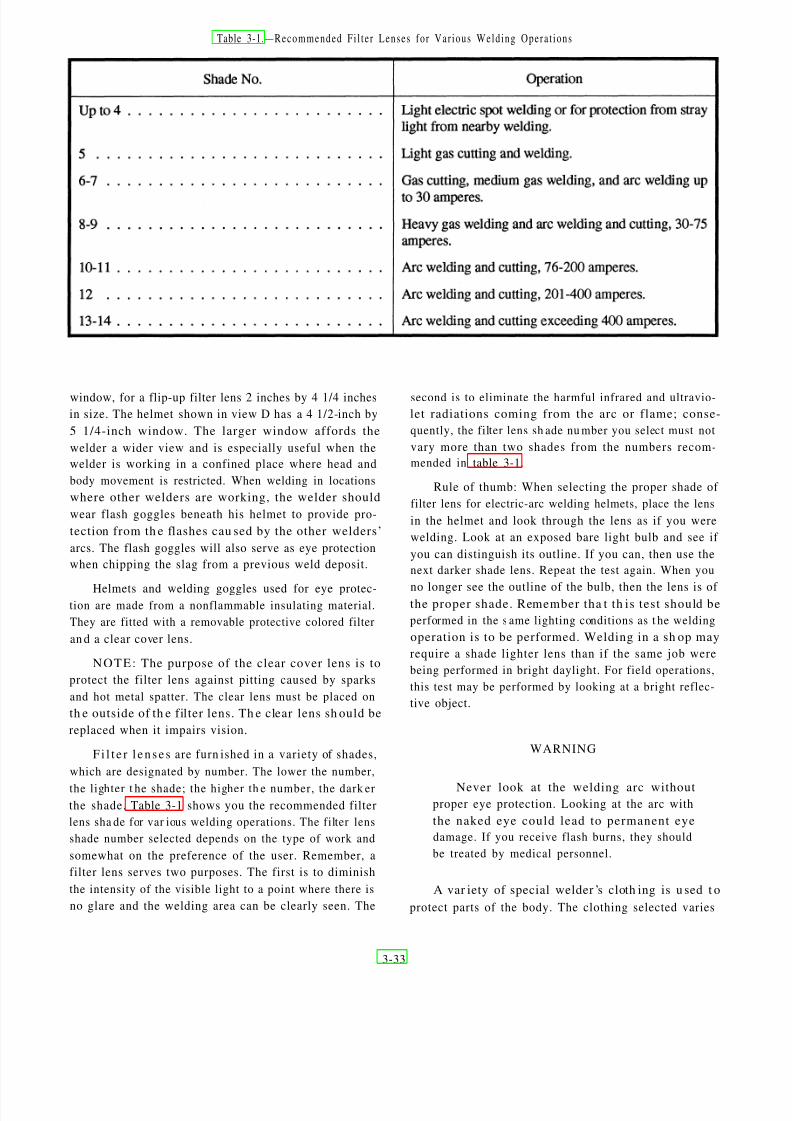
8/8/2019 Steelworker Vol. 1 -14250
http://slidepdf.com/reader/full/steelworker-vol-1-14250 71/246
Table 3-1.—Recommended Fi l te r Lenses for Var ious Welding Opera t ions
window, for a flip-up filter lens 2 inches by 4 1/4 inches second is to eliminate the harmful infrared and ultravio-
in size. The helmet shown in view D has a 4 1/2-inch by
5 1/4-inch window. The larger window affords the
welder a wider view and is especially useful when the
welder is working in a confined place where head and
body movement is restricted. When welding in locations
where other welders are working, the welder should
wear flash goggles beneath his helmet to provide pro-
tection from th e flashes cau sed by the other welders’
arcs. The flash goggles will also serve as eye protection
when chipping the slag from a previous weld deposit.
Helmets and welding goggles used for eye protec-tion are made from a nonflammable insulating material.
They are fitted with a removable protective colored filter
an d a clear cover lens.
NOTE: The purpose of the clear cover lens is to
protect the filter lens against pitting caused by sparks
and hot metal spatter. The clear lens must be placed on
th e outside of th e filter lens. Th e clear lens sh ould be
replaced when it impairs vision.
F i l t e r l en se s are furn ished in a variety of shades,
which are designated by number. The lower the number,
the lighter t he shade; the higher th e number, the dark er
the shade. Table 3-1 shows you the recommended filter
lens sha de for var ious welding operations. The filter lens
shade number selected depends on the type of work and
somewhat on the preference of the user. Remember, a
filter lens serves two purposes. The first is to diminish
the intensity of the visible light to a point where there is
no glare and the welding area can be clearly seen. The
let radiations coming from the arc or flame; conse-
quently, the filter lens sh ade nu mber you select must not
vary more than two shades from the numbers recom-
mended in table 3-1.
Rule of thumb: When selecting the proper shade of
filter lens for electric-arc welding helmets, place the lens
in the helmet and look through the lens as if you were
welding. Look at an exposed bare light bulb and see if
you can distinguish its outline. If you can, then use the
next darker shade lens. Repeat the test again. When you
no longer see the outline of the bulb, then the lens is of the proper shade. Remember tha t th is test should be
performed in the s ame lighting conditions as t he welding
operation is to be performed. Welding in a sh op may
require a shade lighter lens than if the same job were
being performed in bright daylight. For field operations,
this test may be performed by looking at a bright reflec-
tive object.
WARNING
Never look at the welding arc withoutproper eye protection. Looking at the arc with
the naked eye could lead to permanent eye
damage. If you receive flash burns, they should
be treated by medical personnel.
A var iety of special welder ’s cloth ing is u sed t o
protect parts of the body. The clothing selected varies
3-33

8/8/2019 Steelworker Vol. 1 -14250
http://slidepdf.com/reader/full/steelworker-vol-1-14250 72/246
with the size, location, and nature of the work to be
performed. During any welding or cutting operation,
you should always wear flameproof gauntlets. (See fig.
3-57.) For ga s welding a nd cuttin g, five-finger gloves
like those shown in view A should be used. For electric-
arc welding, use the two-finger gloves (or mitts) shown
in view B.
Both types of gloves protect t he ha nds from heat andmetal spatter. The two-finger gloves have an advantage
over t he five-finger gloves in t hat they r educe the da nger
of weld spatter and sparks lodging between the fingers.
They a lso reduce finger chafing which sometimes oc-
curs when five-finger gloves ar e worn for electr ic-arc
welding.
Many light-gas welding and brazing jobs require noFigu re 3-57 .—Weldin g g loves an d mi t t s . special protective clothing other than gloves and
Figure 3-58.—Welder’s protective clothing.
3-34

8/8/2019 Steelworker Vol. 1 -14250
http://slidepdf.com/reader/full/steelworker-vol-1-14250 73/246
goggles. Even her e, it is essen tial th at you wear your
work clothes properly. Sparks are very likely to lodge in
rolled-up sleeves, pockets of clothing, or cuffs of trou-
sers or overalls. Sleeves should be rolled down and the
cuffs butt oned. The sh irt collar, a lso, should be fully
buttoned. Trousers should not be cuffed on the outside,
and pockets not protected by button-down flaps should
be eliminated from the front of overalls and aprons. All
other clothing must be free of oil and grease. Wear hightop-safety sh oes; low-cut sh oes are a ha zard becau se
sparks and molten metal could lodge in them, especially
when you are sitting down.
Medium- and heavy-gas welding, all-electric weld-
ing, and welding in th e vertical or overhead welding
position requ ire special flamepr oof cloth ing ma de of
leather or other suitable material. This clothing is de-
signed to protect you against radiated heat, splashes of
hot metal, or sparks. This clothing consists of aprons,
sleeves, combination sleeves an d bib, jackets, a nd over-
alls. They afford a choice of protection depending uponthe specific nature of the particular welding or cutting
job. Sleeves provide satisfactory protection for welding
operations at floor or bench level.
The cape and sleeves are particularly suited for
overh ead welding, becau se it protects t he back of th e
neck, top of the shoulders, and the upperpart of the back
and chest. Use of the bib, in combination with the cape
and sleeves, gives added protection to the chest and
abdomen. The jacket should be worn when t here is a
need for complete all-around protection to the upperpart
of the body. This is especially true when several welders
are working in close proximity to one another. Aprons
and overalls provide protection t o the legs and a re su ited
for welding operations on the floor. Figure 3-58 shows
some of the protective clothing available to welders.
To prevent hea d burn s dur ing overhead welding
operations, you should wear leather or flameproof caps
under the helmet. Earplugs also should be worn to keep
sparks or splatter from entering and burning the ears.
Where the welder is exposed to falling or sharp objects,
combination welding helmet/hard hats should be used.
For very heavy work, fire-resistant leggings or high
boots should be worn . Shoes or boots ha ving exposed
na ilheads or r ivets should NOT be worn . Oilskins or
plastic clothing must NOT be worn in any welding
operation.
NOTE: If leather protective clothing is not avail-
able, then woolen clothing is preferable to cotton.
Woolen clothing is not as flammable as cotton and helps
protect the operator from the changes in temperature
caused by welding. Cotton clothing, if used, should be
chemically treated to reduce its flammability.
3-35

8/8/2019 Steelworker Vol. 1 -14250
http://slidepdf.com/reader/full/steelworker-vol-1-14250 74/246

8/8/2019 Steelworker Vol. 1 -14250
http://slidepdf.com/reader/full/steelworker-vol-1-14250 75/246
C H A PTER 4
GAS CUTTING
The common meth ods used in cutt ing metal are
oxygas flame cutting, air carbon-arc cutting, and
plasma-arc cutt ing. The meth od used depends on th e
type of meta l to be cut and th e availability of equipment.
As a Steelworker, oxygas or air carbon-arc equipment
is the most common type of equipment available for
your use. Oxygas equipment is explained in this chapter
and air carbon-arc cutting is covered in chapter 7.
The oxygas cutt ing torch h as ma ny uses in st eel-
work. At most naval activities, the Steelworker finds the
cutting t orch a n excellent t ool for cut ting ferrous met als.
This versatile tool is used for operations, such as bevel-
ing plat e, cut ting a nd beveling pipe, piercing holes in
steel plate, and cutting wire rope.
When using the oxygas cutting process, you heat a
spot on the metal to the kindling or ignition temperature
(between 1400°F and 1600°F for steels). The term for
this oxygas flame is the PREHEATING FLAME. Next,
you direct a jet of pure oxygen at the heated metal by
pressing a lever on the cutting torch. The oxygen causes
a chemical reaction known as OXIDATION to take place
rapidly. When oxidation occurs rapidly, it is called
COMBUSTION or BURNING. When it occurs slowly,
it is known as RUSTING.
When you use the oxygas torch method to cut metal,
the oxidation of the metal is extremely rapid and part of
the m etal actually burns. The heat, liberat ed by the
burning of the iron or steel, melts the iron oxide formed
by the chemical reaction and accelerates the preheating
of the object you are cutting. The molten material runs
off as slag, exposing more iron or steel to the oxygen jet.
In oxygas cutting, only that portion of the meta l tha t
is in th e direct pa th of th e oxygen jet is oxidized. The
nar row slit, formed in the m etal as the cutt ing pro-
gresses, is called th e kerf. Most of the material removed
from t he k erf is in t he form of oxides (products of th eoxidation reaction). The remainder of the material is
molten metal that is blown or washed out of the kerf by
the force of the oxygen jet.
The walls of the ker f formed by oxygas cut ting of
ferrous metals should be fairly smooth and parallel to
each other. After developing your skills in handling the
torch, you can keep the cut within close tolerances;
guide the cut along straight, curved, or irregular lines;
and cut bevels or other shapes th at require holding the
torch at an a ngle.
Partial oxidation of the metal is a vital part of the
oxygas cutting process. Because of this, metals that do
not oxidize readily are not suitable for oxygas cutting.
Carbon steels are easily cut by the oxygas process, but
special techniques (described later in this chapter) are
required for the cutting of many other metals.
OXYGAS CUTTING EQUIP MENT
An oxygas cutt ing outfit u sua lly consists of a cylin-
der of acetylene or MAPP gas, a cylinder of oxygen, two
regulators, two lengths of hose with fittings, and a
cutting torch with tips (fig. 4-1). An oxygas cutting
outfit also is referred to as a cutting rig.
In a ddition t o the basic equipment men tioned above,
numerous types of auxiliary equipment are used in
oxygas cutting. An important item is the spark igniter
that is used to light the torch (fig. 4-2, view A). Another
item you u se is an a ppara tus wren ch. It is similar in
design to the one shown in figure 4-2, view B. The
apparatus wrench is sometimes called a gang wrench
becau se it fits all th e connections on the cutting rig. Note
that the wrench shown has a raised opening in th e handlethat serves as an a cetylene tank key.
Other common accessories include tip cleaners, cyl-
inder trucks, clamps, and holding jigs. Personal safety
apparel, such as goggles, hand shields, gloves, leather
aprons, sleeves, and leggings, are essential and should
be worn as required for the job at hand. Information on
safety appar el is also conta ined in chapter 3 of this text.
Oxygas cutting equipment can be stationary or port-
able. A portable oxygas outfit, such as the one shown in
figur e 4-3, is an advantage when it is necessary to move
the equipment from one job to another.
To conduct your cutting requirements, you must be
able to set up the cutting equipment and make the
required adjustments needed to perform the cutting op-
eration. For this reason it is important you understand
the purpose and function of the basic pieces of equip-
ment t hat make u p the cutting outfit. But, before discuss-
ing the equipment, let’s look a t t he gases most often used
in cutting: acetylene, MAPP gas, and oxygen.
4-1

8/8/2019 Steelworker Vol. 1 -14250
http://slidepdf.com/reader/full/steelworker-vol-1-14250 76/246
Figure 4-1.—Oxygas cut t ing outf i t .
F i g u r e 4 -2 .—( A) S p a r k i g n i t e r ; (B) a p p a r a t u s w r e n c h .
4-2

8/8/2019 Steelworker Vol. 1 -14250
http://slidepdf.com/reader/full/steelworker-vol-1-14250 77/246
Figur e 4-3 .—A p o r t a b l e o x y g a s c u t t i n g a n d w e l d i n g o u t f it .
ACETYLENE
Acetylene is a flammable fuel gas composed of
carbon and hydrogen having the chemical formula
C2H 2.When bur ned with oxygen, acetylene pr oduces a
hot flame, having a temperature between 5700°F and
6300°F. Acetylene is a colorless ga s, ha ving a disa gree-
able odor that is readily detected even when the gas ishighly diluted with air. When a portable welding outfit,
similar to the one shown in figure 4-3 is used, acetylene
is obtained directly from the cylinder. In the case of
stationary equipment, similar to the acetylene cylinder
bank sh own in figure 4-4, the acetylene can be piped to
a number of individual cutting stations.
Hazards
Pure acetylene is self-explosive if stored in the free
state under a pressure of 29.4 pounds per square inch(psi). A slight shock is likely to cause it to explode.
WARNING
Acetylene becomes extr emely dan gerous
if used above 15 pounds pressure.
Figure 4-4.—Sta t ionary ace ty lene cy l inder bank .
Cylinder Design
Acetylene can be safely compressed up to 275 psi
when dissolved in acetone and stored in specially de-
signed cylinders filled with porous m at erial, such as
balsa wood, cha rcoal, finely shr edded a sbestos, corn
pith, portland cement, or infusorial earth. These porous
filler m ater ials aid in t he prevention of high-pressure gas
pockets formin g in th e cylinder.
Acetone is a liquid chemical t ha t dissolves large
portions of acetylene under pressure without changing
the nature of the gas. Being a liquid, acetone can be
drawn from an acetylene cylinder when it is not upr ight.
You should not store acetylene cylinders on their side,
but if they are, you mu st let t he cylinder st and u pright
for a minimum of 2 hours before using. This allows the
acetone to settle to the bottom of the cylinder.
NOTE: Acetone contaminates the hoses, regula-
tors, torch, and disrupts the flame.
Acetylene is m easur ed in cubic feet. Th e most com-
mon cylinder sizes a re 130 -, 290-, and 330-cubic-foot
capacity. The sta ndar d size cylinder t he Na vy uses holds
4-3

8/8/2019 Steelworker Vol. 1 -14250
http://slidepdf.com/reader/full/steelworker-vol-1-14250 78/246
Figure 4-5.—Acetylene cylinder.
225 cubic feet of acetylene. Just because a cylinder has
a 225-cubic-foot capacity does not necessarily mean it
has 225 cubic feet of acetylene in it. Because it is
dissolved in acetone, you cannot judge how much acety-
lene is left in a cylinder by gauge pressure. The pressur e
of the acetylene cylinder will remain fairly constant unt il
most of the gas is consumed.
An example of an acetylene cylinder is shown in
figur e 4-5. These cylinders a re equipped with fusible
plugs that relieve excess pressure if the cylinder is
exposed to undo heat. The standard Navy acetylene
cylinder contains 225 cubic feet of acetylene and weighs
about 250 pounds. The acetylene cylinder is yellow, and
all compressed-gas cylinders are color-coded for iden-
tification. More on the color coding of cylinders is
covered later in this chapter.
MAPP GAS
MAPP (methylacetylene-propadiene) is an all-pur-
pose indust rial fuel having the h igh-flame temper atu re
of acetylene but has the handling characteristics of
propane. Being a liquid, MAPP is sold by th e pound,
ra th er th an by the cubic foot, as with acetylene. One
cylinder containing 70 pounds of MAPP gas can accom-
plish the work of more than six and one-half 225-cubic-
foot a cetylene cylinders ; ther efore, 70 pounds of MAPP
gas is equal to 1,500 cubic feet of acetylene.
Cylinder Design
Tota l weight for a MAPP cylinder, which h as t he
same physical size as a 225-cubic-foot acetylene cylin-
der, is 120 pounds (70 pounds which is MAPP gas).
MAPP cylinders contain only liquid fuel. There is no
cylinder packing or acetone to impair fuel withdrawal;
ther efore, the entir e content s of a MAPP cylinder can be
used. For heavy-use situations, a MAPP cylinder deliv-
ers m ore than twice as much gas as an a cetylene cylinder
for the same time period.
MAPP Character i s t ics
Because of its superior heat transfer characteristics,
MAPP produces a flame temperature of 5300°F when
burned with oxygen. MAPP equals, or exceeds, the
performance of acetylene for cutting, heating, and braz-
ing.
MAPP is not sensitive to shock a nd is n onflamma -
ble in the absence of oxygen. There is no chance of an
explosion if a cylinder is bu mped , jar red , or dr opped.
You can store or transport the cylinders in any position
with no danger of forming an explosive gas pocket.
The chara cteristic odor, while ha rmless, gives war n-
ings of fuel leaks in the equipment long before a dan-
gerous condition can occur. MAPP gas is not restricted
to a m aximum working pressu re of 15 psig, as is a cety-
lene. In jobs requiring higher pr essures a nd gas flows,
MAPP can be used safely at the full-cylinder pressure
of 95 psig at 70°F. Because of this, MAPP is an excellent
gas for underwater work.
Bulk MAPP Gas
Bulk MAPP gas facilities, similar to liquid oxygen
sta tions, are insta lled at some activities where large
supplies of the gas are used. In bulk installations, MAPP
gas is delivered th rough a piping system directly to the
user points. Maximum pressure is controlled centrally
for efficiency and economy.
Cylinder-filling facilities are also available from
bulk installations that allow users to fill their cylinders
on site. Filling a 70-pound MAPP cylinder ta kes one
man about 1 minute a nd is essentially like pumpingwater from a large tank to a smaller one.
MAPP Gas Safety
MAPP gas vapor is sta ble up to 600°F a nd 1,100
psig when exposed to an 825°F probe. The explosive
limits of MAPP gas are 3.4 percent to 10.8 percent in air
or 2.5 percent to 80 percent in oxygen. As shown in
4-4

8/8/2019 Steelworker Vol. 1 -14250
http://slidepdf.com/reader/full/steelworker-vol-1-14250 79/246
Figure 4-6.—Explos ive l imi t s of MAPP and ace ty lene in a i r .
Figure 4-7.—Typical oxygen cylinder.
figure 4-6, you can see these limits are narrow in com-
parison with that of acetylene.
MAPP gas has a highly detectable odor. The smell
is detectable at 100 ppm, or a t a concentra tion of 1/340th
of its lower explosive limit. Sma ll fuel-gas system s m ay
leak 1 or 1 1/2 pounds of fuel or more in an 8-hour shift;
bulk system s will leak even more. Fuel-gas leak s ar e
often difficult to find and often go unnoticed; however,
a MAPP gas leak is easy to detect and can be repairedbefore it becomes dangerous.
MAPP toxicity is rated “very slight,” but high con-
centrations (5,000 ppm) may have an anesthetic effect.
Local eye or skin contact with MAPP gas vapor causes
no adver se effect; however, th e liquid fuel can cau se
dangerous frostlike burns due to the cooling caused by
the rapid evaporation of the liquid.
The identification markings on a MAPP cylinder are
a yellow body with band “B” colored orange and the top
yellow.
corrosion of aluminum are all due to the action of
atmospheric oxygen. This action is known as oxidation.
Oxygen is obtained commercially either by the
liquid-air process or by the electrolytic process. In the
liquid-air process, the air is compressed and then
cooled to a point where th e gases become liquid (ap-
proximately –375°F). The temperature is then raised to
above –321 ‘F, at which point t he n itrogen in t he a ir
becomes gas again and is removed. When the tempera-
ture of the remaining liquid is raised to –297°F, the
oxygen forms gas and is drawn off. The oxygen is
further purified and compressed into cylinders for use.
The other process by which oxygen is produced—
the electrolytic process—consists of running an electri-
cal curr ent t hrough water t o which an acid or an a lkali
has been added. The oxygen collects at the positive
terminal and is drawn off through pipes to a container.
Oxygen is supplied for oxyacetylene welding inseamless steel cylinders. A typical oxygen cylinder is
shown in figure 4-7. The color of a sta nda rd oxygen
cylinder used for industrial purposes is solid green.
Oxygen cylinders ar e ma de in severa l sizes. The size
most often used in welding and cutting is the 244-cubic-
foot capacity cylinder. This cylinder is 9 inches in di-
ameter, 51 inches high, and weighs about 145 pounds
and is charged to a pressure of 2,200 psi at 70°F.
OXYGEN
Oxygen is a colorless, ta steless, an d odorless gas
and is slightly heavier tha n air. It is nonflammable but
supports combustion with other elements. In its free
sta te, oxygen is one of the m ore common elements. Th e
atmosphere is made up of about 21 parts of oxygen and
78 parts of nitrogen, the remainder being ra re gases.
Rusting of ferrous metals, discoloration of copper, and
4-5

8/8/2019 Steelworker Vol. 1 -14250
http://slidepdf.com/reader/full/steelworker-vol-1-14250 80/246
You can determ ine th e am ount of oxygen in a com-
pressed-gas cylinder by reading the volume scale on the
high-pressure gauge attached to the regulator.
REGULATORS
You must be able to reduce the high-pressure gas in
a cylinder to a working pressure before you can use it.
This pressure reduction is done by a regulator or reduc-
ing valve. The one basic job of all regulators is to take
the high-pressure gas from the cylinder and reduce it to
a level that can be safely used. Not only do they control
the pressure but they also control the flow (volume of
gas per hour).
Regulators come in a ll sizes an d types. Some ar e
designed for high-pressure oxygen cylinders (2,200
psig), while others are designed for low-pressure gases,
such as n at ur al gas (5 psig). Some gases like nitr ous
oxide or carbon dioxide freeze when t heir p ressu re is
reduced so they require electrically heated regulators.
Most regulators have two gauges: one indicates the
cylinder pressur e when t he valve is opened and the other
indicates the pressure of the gas coming out of the
regulator. You must open the regulator before you get a
reading on the second gauge. This is the delivery pres-
sure of the gas, and you mu st set t he pressure th at you
need for your part icular job.
The pressures that you read on regulator gauges is
called gauge pressure. If you are using pounds per
square inch, it should be written as psig (this acronym
means pounds per square inch gauge). When the gauge
on a cylinder reads zero, this does not mean tha t t hecylinder is empty. In actuality, the cylinder is still full of
gas, but the pressure is equal to the surrounding atmos-
pheric pressur e. Remember: no gas cylinder is empt y
unless it has been pumped out by a vacuum pump.
There are two types of regulators that control the
flow of gas from a cylinder. These are either single-stage
or double-stage regulators.
Single-Stage Regulators
Regulators are used on both high- and low-pressuresystems. Figure 4-8 shows two SINGLE-STAGE regu-
lators: one for acetylene and one for oxygen. The regu-
lator mechanism consists of a nozzle through which the
gases pa ss, a va lve seat to close off th e nozzle, a dia -
phragm, an d balancing springs. These mechan isms are
all enclosed in a suitable housing. Fuel-gas regulators
and oxygen regulators are basically the same design.
The difference being those designed for fuel gases are
Figure 4-8.—Single-stage regulators.
not made t o withsta nd t he high pressures t hat oxygen
regulators are subjected to.
In the oxygen regulator, the oxygen enters through
the high-pressure inlet connection and passes through a
glass wool falter t hat removes dust a nd dirt. Tur ning the
adjusting screw IN (clockwise) allows the oxygen to
pass from the high-pressure chamber to the low-pres-
sur e cha mber of th e regulator, through th e regulator
outlet, and thr ough th e hose to the torch. Turning th e
adjusting screw further clockwise increases the working
pressure; turning it counterclockwise decreases the
working pressure.
The high-pressure gauge on an oxygen regulator is
gradu at ed from 0 t o 3,000 psig and from 0 to 220 in
cubic feet. This allows readings of the gauge to deter-
mine cylinder pressure and cubic content. Gauges are
calibrated to read correctly at 70°F. The working pres-
sure gauge may be graduated in “psig” from 0 to 150,
0 to 200, or from 0 to 400, depending upon the type of
regulator used. For example, on regulators designed for
4-6

8/8/2019 Steelworker Vol. 1 -14250
http://slidepdf.com/reader/full/steelworker-vol-1-14250 81/246
Figure 4-9.—Double-stage regulator.
heavy cutting, the working pressure gauge is graduated
from 0 to 400.
The major disadvantage of single-stage regulators
is that the working gas pressure you set will decrease as
th e cylinder pressu re decreases; therefore, you mu st
constantly monitor and reset the regulator if you require
a fixed pressure and flow rate. Keeping the gas pressure
and flow rate constant is too much to expect from a
regulator that has to reduce the pressure of a full cylinder
from 2,200 psig to 5 psig. This is where double-stage
regulators solve the problem.
Double-Stage Regulators
The double-stage regulator is similar in principle to
the one-stage regulator. The main difference being that
the total pressure drop takes place in two stages instead
of one. In the high-pressure stage, the cylinder pressure
is reduced to an intermediate pressure t hat was prede-
termined by the manufacturer. In the low-pressure stage,
the pr essure is again r educed from th e intermediate
pressu re to th e workin g pressur e you ha ve chosen. A
typical double-stage regulator is shown in figure 4-9.
Problems and Safe ty
Regulators a re pr ecise an d complicat ed pieces of
equipment. Carelessness can do more to ruin a regulator
than any other gas-using equipment. One can easily
damage a regulator by simply forgetting to wipe clean
the cylinder, regulator, or hose connections. When you
open a high-pressure cylinder, the gas can rush into the
regulator at the speed of sound. If there is any dirt
present in th e conn ections, it will be blasted int o the
precision-fitted valve seats, causing them to leak This
results in a condition that is known as creep. Creep
occurs when you shut of the regulator but not the cylin-
der and gas pressure is still being delivered to the
low-pressure side.
Regulators are built with a minimum of two relief
devices that protect you and the equipment in the case
of regulator creep or high-pressure gas being released
into the regulator all at once. All regulator gauges have
blowout backs that release the pressure from the back
of th e gau ge before th e gau ge glass explodes. Nowa-
days, most manufacturers use shatterproof plastic in-
stead of glass.
The regulator body is also protected by safety de-
vices. Blowout disks or spring-loaded relief valves are
the two most common types of devices used. When a
blowout disk ruptures, it sounds like a cannon. Spring-
loaded relief valves usually make howling or shrieking
like noises. In either case, your first action, a fter you
recover from your initial fright, should be to turn off the
cylinder valve. Remove the r egulator an d t ag it for repa ir
or disposal.When opening a gas cylinder, you should just
“crack” the valve a little. This should be done before
attaching the regulator and every time thereafter. By
opening the cylinder before connecting the regulator,
you blow out any dirt or other foreign material that
might be in the cylinder nozzle. Also, there is the
4-7

8/8/2019 Steelworker Vol. 1 -14250
http://slidepdf.com/reader/full/steelworker-vol-1-14250 82/246

8/8/2019 Steelworker Vol. 1 -14250
http://slidepdf.com/reader/full/steelworker-vol-1-14250 83/246
Figure 4-11.—One p iece oxygas cu t t ing torch .
Figure 4-12 .—Cut t ing a t tachment for combina t ion torch .
an additional tube for high-pressure cutting oxygen.The
flow of high-pressure oxygen is controlled from a valve
on the handle of the cutting torch. In the standard cutting
torch, the valve may be in the form of a tr igger a ssembly
like the one in figur e 4-11. On most torches, the cutting
oxygen mechan ism is designed s o the cut ting oxygen
can be turned on gradually. The gradual opening of the
cutt ing oxygen valve is par ticularly helpful in opera-
tions, such as hole piercing and rivet cutting.
Torch Body
Most welding t orches ar e designed so th e body of
the torch can accept either welding tips or a cutting
attachment. This type of torch is called a combination
torch. The advantage of this type of torch is the ease in
changing from the welding mode to the cutting mode.
There is no need to disconnect the hoses; you just
unscrew the welding tip and then screw on t he cutting
attachment. The high-pressure cutting oxygen is con-
trolled by a lever on th e torch han dle, as shown in figure
4-12.
Cut t ing Torch Tips
As in welding, you must use the proper size cutting
tip if quality work is to be done. The prehea t flames mu st
furnish just the right amount of heat, and the oxygen jet
orifice must deliver the correct amount of oxygen at just
the right pressure and velocity to produce a clean cut.
All of this must be done with a minimum consumption
of oxygen and fuel gases. Careless workers and workers
not acquainted with the correct procedures waste both
oxygen a nd fuel gas. This does not seem importa nt when
you a re working in a shop, but if you a re deployed, it
4-9

8/8/2019 Steelworker Vol. 1 -14250
http://slidepdf.com/reader/full/steelworker-vol-1-14250 84/246
Figure 4-13.—C om m on cu t t i ng to r ch t i p s an d the i r u ses .
becomes critical due to the long lead time between chases its cutting and welding equipment, there is the
resupply. possibility of having two or three different types of
Each manufacturer makes many different types of cutting torches in your kits. Make sur e that the cutting
cutting tips. Although the orifice arrangements and the t ips match the cutting attachment and ensure that the
t ip mater ia l are much the same among the manufactur - cut t ing at tachment matches the torch body. Figure 4-13
ers, the part of the tip that fits into the torch head often shows the different styles of tips, their orifice arrange-
differs in design. Because of the way the Navy pur- ments, and t heir uses. The tips and seats ar e designed to
4-10

8/8/2019 Steelworker Vol. 1 -14250
http://slidepdf.com/reader/full/steelworker-vol-1-14250 85/246
127.376
Figu r e 4-14.—Fou r cu t t i ng -t i p cond i t i ons .
produce a even flow of gas and to keep themselves ascool as possible. The seats must produce leakproof
joints. If the joints leak, the preheat gases could mix
with the cutting oxygen or escape to the atmosphere,
resu lting in poor cut s or th e possibility of flash backs.
To make clean and economical cuts, you must
keep the tip orifices and passages clean and free of
burrs and slag. If the tips become dirty or
misshapen ed, they should be put aside for restoration.
Figure 4-14 shows four tips: one that is repairable,
two that need replacing, and one in good condition.
Since it is extremely important that the sealing
sur faces be clean a nd free of scrat ches or bu rr s, storethe tips in a container that cannot scratch the seats.
Aluminum racks, plastic racks, and wood racks or
boxes make ideal storage cont ainers.
TIP MAINTENANCE.— In cutting operations,
the stream of cutting oxygen sometimes blows slag
and molten metal into the tip orifices which partially
clogs them. When this happens, you should clean the
orifices thoroughly before you use the tip again. A
small amount of slag or metal in an orifice will
seriously interfere with the cutting operation. You
should follow the recommendations of the torch
manufacturer as to the size of drill or tip cleaner to
use for cleaning the orifices. If you do not have a tip
cleaner or drill, you may use a piece of soft copper
wire. Do not use twist drills, nails, or welding rods for
cleaning t ips becau se th ese items ar e likely to enlar ge
an d distort th e orifices.
Clean the orifices of the cutting torch tip in the
same man ner as t he single orifice of th e welding torch
tip. Remember: the proper technique for cleaning the
tips is to push the cleaner straight in and out of theorifice. Be careful not to turn or twist the cleaning
wire. Figure 4-15 shows a typical set of tip cleaners.
Occasionally the cleaning of the tips causes
enlargemen t a nd distortion of th e orifices, even when
using the proper tip cleaners. If the orifices become
enlarged, you will get shorter and thicker preheating
flames; in addition, the jet of cutting oxygen wil
spread, rather than leave the torch, in the form of a
long, thin stream. If the orifices become belled for a
short distance at the end, you can sometimes correct
this by rubbing the tip back and forth against emery
cloth placed on a flat surface. This action wears downthe end of the t ip where th e orifices ha ve been belled
thus bringing the orifices back to their original size
Obviously, this procedure will not work if the damage
is great or if the belling extends more than a slight
dista nce into th e orifice.
After reconditioning a tip, you may test it by lighting
the torch and observing the prehea ting flames. If the
Figu r e 4-15 .—Ti p c l ean e r s .
4-11

8/8/2019 Steelworker Vol. 1 -14250
http://slidepdf.com/reader/full/steelworker-vol-1-14250 86/246
Figure 4-16.—MAPP gas cu t t ing t ips .
flames are too short, the orifices are still partially
blocked. If the flames snap out when you close the
valves, the orifices are still distorted.
If the t ip seat is dirt y or scaled and does not pr operly
fit int o the torch h ead, heat t he tip to a du ll red and
quench it in water. This will loosen the scale and dirt
enough so you can rub it off with a soft cloth.
MAP P GAS CUTTING TIPS.— Four basic types
of MAPP gas cutting tips are used: two are for use with
standard pressures and normal cutting speeds, and two
are for use with high pressures and high cutting speeds.
Only the standar d pressure tips, types S P and FS , will
be covered here since they are the ones that Steelwork-
ers will most likely use. SP stands for standard pressure
and FS for fine standard.
The SP tip (fig. 4-16, view A) is a one-piece standard
pressur e tip. It is used for cutt ing by hand, especially by
welders who are accustomed to one-piece tips. SP tips
ar e more likely to be used in situa tions where MAPP gas
is replacing acetylene as the fuel gas.
The FS tip (fig. 4-16, view B) is a two-piece, fine
spline, standard pressure tip. It is used for cutting by
hand as well as by machine. Welders accustomed to
two-piece cut ting tips will use them in ha nd cutt ing,
especially when MAPP gas is replacing natural gas or
propane as the fuel gas. The FS tips will produce heavier
preheating flames and faster starts than the SP tips;
however, two-piece tips will not take as much thermal
or physical abuse as one-piece tips. But in the hands of
skilled Steelworkers, they should last as long as one-
piece tips.
Recommended tip sizes and gas pressures for use in
cutting different thicknesses of steel using MAPP gas as
a fuel are given in table 4-1.
Table 4-1.—Recommended MAPP Gas Tip S izes and Oxyfue l Pressures
4-12

8/8/2019 Steelworker Vol. 1 -14250
http://slidepdf.com/reader/full/steelworker-vol-1-14250 87/246
OXYGAS CUT TING OP ER ATIONS
Before you begin a cutting operation with an oxygas
cutting torch, make a thorough inspection of the area.
Ensure that there are no combustible materials in the
area that could be ignited by the sparks or slag produced
by the cutting operation. If you are burning into a wall,
inspect the opposite side of the wall, and post a fire
watch as r equired.
EQUIPMENT SETUP
Setting up the oxygas equipment and preparing for
cutting must be done carefully and systematically to
avoid costly mista kes. To ensur e your own sa fety, as
well as t he sa fety of your cowork ers a nd equ ipment ,
make sure the following steps are taken before any
attempt is made to light the torch:
l Secure the cylinders so they cannot be accidently
knocked over. A good way to do this is to either put them
in a corner or next to a vertical column and then secure
them with a piece of line. After securing the cylinders,
remove the protective caps. Cylinders should never be
secured to a structural member of a building that is a
current conductor.
l Sta nding t o one side, crack each cylinder valve
slightly an d th en imm ediately close th e valve again. This
blows an y dirt or other foreign m at ter out of the cylinder
valve nozzle. Do not bleed fuel gas into a confined area
because it may ignite. Ensure the valves are closed and
wipe the connections with a clean cloth.
c Connect the fuel-gas regulator to the fuel-gascylinder and the oxygen regulator to the oxygen
cylinder. Using a gang wrench, snug the connection nuts
sufficiently to avoid leaks.
l Back off the regulator screws to prevent damage
to the regulators and gauges and open the cylinder
valves slowly. Open the fuel-gas valve only one-half
turn and the oxygen valve all the way. Some fuel-gas
cylinders h ave a h an dwheel for opening th e fuel-gas
valve while others require the use of a gang wrench or
T-handle wrench. Leave the wrench in place while the
cylinder is in use so the fuel-gas bottle can be turned off quickly in an emergency. Read the high-pressure gauge
to check t he cont ents in each cylinder.
l Connect the RED hose to the fuel-gas regulator
and the GREE N hose to the oxygen regulator. Notice th e
left-hand threads on the fuel-gas connection.
l To blow out the oxygen hose, turn the regulator
screw in (clockwise) and adjust the pressure between 2
and 5 psig. After t he hose has been pur ged, tur n t he
screw back out again (counterclockwise) to shutoff the
oxygen. Do th e sam e for t he fuel-gas hose, but do it
ONLY in a well-ventilated place tha t is free from spar ks,
flames, or other possible sources of ignition.
. Connect the hoses to the torch. The RED
(fuel-gas) hose is connected to the connection gland
with the needle valve marked “FUEL.” The GREEN
(oxygen) hose is connected to the connection gland withthe needle valve marked “OXY.”
l With the torch valves closed, turn both regulator
screws clockwise to test the hose connections for leaks.
I f none a re found , t u rn the r egu la to r s c rew s
counterclockwise and drain the hose by opening the
torch valves.
Q Select the correct cutting tip and install it in the
cutt ing torch hea d. Tighten t he assembly by han d, and
then tighten with your gang wrench.
l Adjust the working pressures. The fuel-gaspressure is adjusted by opening the torch needle valve
and turning the fuel-gas regulator screw clockwise.
Adjust the regulator to the working pressure needed for
the particular tip size, and then close the torch needle
valve. To adjust MAPP gas, you should set the gauge
pressure with the torch valves closed. To adjust the
oxygen working pressure, you should open the oxygen
torch needle valve and proceed in the same manner as
in adjusting the fuel-gas pressure.
In lighting the torch and adjusting the flame, always
follow the manufacturer’s directions for the particular
model of torch being used. This is necessary because t he
procedure varies somewhat with different types of
torches and, in some cases, even with different models
made by the same manufacturer.
In genera l, the procedure u sed for lighting a t orch is
to first open the torch oxygen needle valve a small
amount and the torch fuel-gas needle valve slightly
more, depending upon th e type of torch. The mixtur e of
oxygen and fuel gas coming from the torch tip is then
lighted by means of a spark igniter or stationary pilot
flame.
CAUTION
NEVER use ma tches to light th e torch; their
length requires bringing the hand too close to
the tip. Accumulated gas may envelop the hand
and, u pon igniting, result in a severe burn . Also,
never light the torch from hot metal.
4-13

8/8/2019 Steelworker Vol. 1 -14250
http://slidepdf.com/reader/full/steelworker-vol-1-14250 88/246
Figur e 4-17 .—MAPP-gas f lames.
After checking t he fuel-gas a djustmen t, you can
adjust the oxygas flame to obtain the desired charac-
teristics for t he work a t h and, by furt her m anipulating
the oxygen and fuel-gas needle valves according to thetorch manufacturer’s direction.
There a re t hree t ypes of gas flames commonly used
for all oxygas processes. They are carburizing, neutral,
and oxidizing. To ensure proper flame adjustment, you
should know the characteristics of each of these three
types of flame. Figure 4-17 shows how the three differ-
ent flames look when using MAPP gas as the fuel.
A pure fuel-gas flame is long and bushy and has a
yellowish color. It takes the oxygen it needs for combus-
tion from the surrounding air. The oxygen available is
not sufficient enough to burn the fuel gas completely;therefore, the flame is smokey and consists of soot. This
flame is not suitable for use. You need to increase the
amount of oxygen by opening the oxygen needle valve
until the flame takes on a bluish white color, with a
bright inner cone surrounded by a flame envelope of a
darker hue. It is the inner cone that develops the required
operating temperature.
CARBURIZING FLAME.— The carburizing
flame always sh ows dist inct colors; th e inn er cone is
bluish white, the intermediate cone is white, the outer
envelope flame is light blue, and the feather at the tip of the inner cone is greenish. The length of the feather can
be used as a basis for judging the degree of carburiza-
tion. The highly carburizing flame is longer with yellow
or white feathers on the inner cone, while the slightly
carburizing flame has a shorter feather on the inner cone
and becomes more white. The temperature of carburiz-
ing flames is about 5400°F.
Strongly carburizing flames are not used in cutting
low-carbon steels because t he a dditional carbon th ey
add causes embrittlement an d har dness. These flames
ar e ideal for cut ting cast iron becau se the a dditional
carbon poses no problems and the flame adds more heat
to the metal because of its size.
Slight ly car burizing flames ar e ideal for cut ting
steels and other ferrous metals tha t pr oduce a large
amount of slag. Although a n eutr al flame is best for most
cutting, a slightly carburizing flame is ideal for produc-ing a lot of hea t down inside th e kerf. It mak es fairly
smooth cuts and reduces the amount of slag clinging to
the bottom of the cut.
NEUTRAL FLAME.— The most common preheat
flame for oxygas cutting is the neutral flame. When you
increase t he oxygen, th e carbur izing flame becomes
neutral. The feather will disappear from the inner flame
cone and a ll that will be left is the dar k blue inner flame
and t he lighter blue outer cone. The temperat ure is about
5600°F.
The neu tr al flame will not oxidize or add car bon t othe m etal you ar e cutt ing. In actuality, a neutr al flame
acts like the inert gases that are used in TIG and MIG
welding to protect the weld from the atmosphere. When
you hold a neutral preheat flame on one spot on the metal
until it melts, the molten puddle that forms looks clear
and lies very quietly under the flame.
OXIDIZING FLAME.— When you add a little
more oxygen t o the pr eheat flame, it will quickly be-
come shorter. The flame will start to neck down at the
base, next to the flame ports. The inner flame cone
changes from dark blue to light blue. Oxidizing flames
are much easier to look at because they are less radiant
than neutral flames. The temperature is about 6000°F.
The oxidizing flame is rarely used for conventional
cutting because it produces excessive slag and does not
leave squar e-cut edges. Oxidizing flames ar e used in
conjunction with cutting machines that have a high-low
oxygen valve. The machine st ar ts t he cut with a oxidiz-
ing flame then automatically reverts to a neutral flame.
The oxidizing flame gives you fast sta rt s when using
high-speed cutting machines and is ideal for piercing
holes in plate. Highly oxidizing flames are only used in
cutting metal underwater where the only source of oxy-gen for t he t orch is su pplied from th e sur face.
CUTTING MILD-CARBON STEEL
To cut mild-carbon steel with t he oxygas cutt ing
torch, you should adjust the preheating flames to neutral.
4-14

8/8/2019 Steelworker Vol. 1 -14250
http://slidepdf.com/reader/full/steelworker-vol-1-14250 89/246
Figure 4-19.—The ef fec t of moving a cu t t ing torch too rap id lya c r o s s t h e w o r k .
Figure 4-18.—Posi t ion of to rch t ip for s ta r t ing a cu t .
Hold the torch perpendicular to the work, with the inner
cones of the pr eheat ing flames about 1/16 inch above
the end of the line to be cut (fig. 4-18). Hold the torch
in this position until the spot you are heating is a bright
red. Open the cutting oxygen valve slowly but steadily
by pressing down on the cutting valve lever.
When th e cut is star ted corr ectly, a shower of spar ks
will fall from the opposite side of the work, indicating
tha t t he flame ha s pierced the met al. Move the cutting
torch forward along the line just fast enough for theflame to continue to penetrate the work completely. If
you h ave ma de th e cut pr operly, you will get a clean ,
narrow cut that looks almost like it was made by a saw.
When cutt ing round bar s or hea vy sections, you can s ave
preheating time by raising a small burr with a chisel
where the cut is to begin. This small raised portion will
heat quickly, allowing you to start cutting immediately.
Once you start the cut, you should move the torch
Slowly along t he cut ting m ar k or guide. As you move
the torch along, watch the cut so you can tell how it is
progressing. Adjust the torch as necessary. You mustmove the torch at the correct speed, not too fast and not
too slow. If you go too slowly, the preheating flame
melts the top edges along the cut and could weld them
back together again. If you go too rapidly, the flame will
not penetrate completely, as shown in figure 4-19. When
this happens, sparks and slag will blow back towards
you. If you have to restart the cut, make sure there is no
slag on the opposite side.
Figure 4-20.—Re c o mme n d e d p r o c e d u r e f o r cu t t i n g t h i n s t e e l .N o t ic e t h a t t h e t w o p r e h e a t f la m e s a r e i n l in e w i t h t h e c u t(kerf) .
Cut t ing Thin Stee l
When cutting steel 1/8 inch or less in thickness, use
the smallest cutting tip available. In addition, point the
tip in the direction the torch is traveling. By tilting the
tip, you give the preheating flames a chance to heat themetal ahead of the oxygen jet, as shown in figure 4-20.
If you hold the t ip perpen dicular to th e sur face, you
decrease the amount of preheated metal and the adjacent
metal could cool the cut enough to prevent smooth
cutting action. Many Steelworkers actually rest the edge
of the t ip on t he meta l during th is process. If you use this
method, be careful to keep the end of the pr eheating
flame inner cone just above the metal.
4-15

8/8/2019 Steelworker Vol. 1 -14250
http://slidepdf.com/reader/full/steelworker-vol-1-14250 90/246
Figu re 4-21.—Pr ogress of a cu t in t h ick s tee l . A. Prehea t f lames a re 1 /16 to 1/8 inch f rom th e meta l sur face . Hold th e torch in th i s spotunt i l the meta l becomes cher r y red . B. Move the tor ch s lowly to main ta in the r ap id oxida t ion , even though t he cu t i s on ly par t ia l lythrough the meta l . C . The cu t i s made through the en t i re th ickness ; the bot tom of the ker f lags behind the top edge s l igh t ly .
Cut t ing Thick Stee l
Steel, that is greater than 1/8 inch thick, can be cut
by holding the torch so the tip is almost vertical to the
surface of the met al. If you a re r ight-handed, one method
to cut steel is to start at the edge of the plate and move
from right to left. Left-handed people tend to cut left to
right. Either direction is correct and you may cut in the
direction that is most comfortable for you. Figure 4-21
shows the progress of a cut in thick steel.
After heating the edge of the steel to a dull cherryred, open the oxygen jet all the way by pressing on the
cutting lever. As soon as the cutting action starts, move
the torch tip at a even rate. Avoid unsteady movement
of the torch to prevent irregular cuts and premat ure
stopping of the cutting action.
To sta rt a cut quicker in thick plate, you sh ould start
at the edge of the metal with t he torch angled in the
opposite direction of travel. When the edge starts to cut,
bring the torch to a vertical position to complete the cut
thr ough th e total thickness of the meta l. As soon a s th e
cut is through the metal, start moving the torch in thedirection of travel.
Two other methods for starting cuts are used. In the
first meth od, you n ick t he edge of th e meta l with a cold
chisel at the point where the cut is to start. The sharp
edges of the metal upset by the chisel will preheat and
oxidize rapidly under the cutting torch, allowing you to
start the cut without preheating the entire edge of the
plate. In the second method, you place an iron filler rod
at the edge of a thick plate. As you apply the preheat
flam es to th e edge of the plat e, the filler r od rapidly
reaches the cherry red t emperatur e. At t his point, tur n
the cutting oxygen on an d th e rod will oxidize and cause
the thicker plate to start oxidizing.
CUTTING CAST IRON
It is m ore difficult to cut cast iron th an steel becaus e
the iron oxides in cast iron melt at a higher temperature
than the cast iron itself. Before you cut cast iron, it is
best to preheat the whole casting to prevent stress frac-
tures. Do not h eat th e casting to a temperatu re tha t is too
high, as this will oxidize the surface and make cutting
Figu re 4-22.—T o r c h m o v e m e n t s f o r c u t t i n g c a s t i r o n .
4-16

8/8/2019 Steelworker Vol. 1 -14250
http://slidepdf.com/reader/full/steelworker-vol-1-14250 91/246
Figure 4-24.—Using angle i ron to cu t bevels on s tee l p la te .
Figure 4-23.—Typical gouging operation using a low-velocityc u t t i n g j e t fo r b e t t e r c o n t r o l o f d e p t h a n d w i d t h .
more difficult. A preheat temperature of about 500°F is
normally satisfactory.
When cutting cast iron, adjust the preheating flame
of th e torch to a carbur izing flam e. This prevents t he
formation of oxides on the surface and provides better
preheat. The cast-iron k erf is always wider tha n a steel
kerf due to the presence of oxides and the torch move-
ment. The torch movement is similar to scribing semi-
circles along th e cuttin g line (fig. 4-22). As th e metal
becomes molten, trigger the cutting oxygen and use its
force to jet the molten metal out of the kerf. Repeat this
action until the cut is complete.
Becau se of the difficulty in cuttin g cast ir on with
th e usu al oxygas cuttin g torch, other m ethods of cut-
ting were developed. These include the oxygen lance,carbon-arc powder, inert-gas cutting, and plasma-arc
methods.
GOUGING MILD STEE L
Cutting curved grooves on the edge or surface of a
plate and removing faulty welds for rewelding are addi-
tional uses for the cutting torch. The gist of groove
cuttin g or gouging is bas ed on t he u se of a lar ge orifice,
low-velocity jet of oxygen instead of a high-velocity jet.
The low-velocity jet oxidizes the surface metal only and
gives better control for more accurate gouging. By
varying the travel speed, oxygen pressure, and the angle
between th e tip an d plate, you can m ake a variety of
gouge contours.
A gouging tip usually has five or six preheat orifices
that provide a more even preheat distribution. Automatic
machines can cut grooves to exact depths, remove bad
spots, and rapidly prepare metal edges for welding.
Figure 4-23 shows a typical gouging operation.
If the gouging cut is n ot s tar ted pr operly, it is possi-
ble to cut accidently through the entire thickness of the
plate. If you cut too shallow, you can cause the operation
to stop. The travel speed of the torch along the gouge
line is important. Moving too fast creates a narrow,shallow gouge and moving too slow creates the oppo-
site; a deep, wide gouge.
BEVELING MILD STEEL
Frequently, you must cut bevels on plate or pipe to
form joints for welding. The flame mus t actua lly cut
th rough 2.8 inches of meta l to mak e a bevel cut of 45
degrees on a 2-inch steel plate. You must take this into
consideration when selecting the tip and adjusting the
pressures. You use more pressure and less speed for a
bevel cut than for a straight cut.
When bevel cutting, you adjust the tip so the pre-
heating orifices straddle the cut. Apiece of l-inch angle
iron, with th e an gle up, makes a n excellent guide for
beveling straight edges. To keep the angle iron in place
while cutting, you should use a heavy piece of scrap, or
ta ck-weld the an gle to th e plate being cut. Move the
torch along this guide, as shown in figure 4-24.
ELECTRIC DRIVE CUTTING
TORCH CARRIAGE
An improvement over mechanical guides is an elec-
tric motor-driven cutting torch carriage. The speed of
th e motor can be varied allowing th e welder t o cut to
dimensions and to cut at a specific speed. A typical
motor driven carriage has four wheels: one driven by a
reduction gear, two on swivels (castor style), and one
freewheeling. The torch is mounted on the side of the
carriage and is adjusted up and down by a gear and rack
4-17

8/8/2019 Steelworker Vol. 1 -14250
http://slidepdf.com/reader/full/steelworker-vol-1-14250 92/246
127.383
Figu re 4-25 .—El ec t r i c m o t o r - d r i ven ca r r i age be i n g us ed t o cu t a c i r c l e in s t e e l p l a t e .
The r ack is a pa rt of the special torch. The torch a lso can
be tilted for bevel cuts. This machine comes with a
straight two-groove track and has a radial bar for use in
cutting circles and arcs. A motor-driven cutting torch
cutting a circle is shown in figur e 4-25. The carriage is
127.384
Figu re 4-26.—Electric motor -dr iven carr iage being used
on stra ight track to cut a beveled edge on steel plate.
equipped with an off-and-on switch, a reversing
switch, a clutch, and a speed-adjusting dial that is
calibrat ed in feet per m inut e.
Figure 4-26 shows an electric drive car riage on a
straight track being used for plate beveling. The
operator must ensure that the electric cord and gas
hoses do not become entan gled on anyth ing during t he
cutting operation. The best way to check for hose
electric cord, and torch clearance is to freewheel the
carriage th e full length of the tra ck by ha nd.
You will find th at the torch car riage is a valua bl
asset during deployment. This is especially true i
your shop is called upon to produce a number o
identical parts in quantity. Such an assignment migh
involve the fabrication of a large supply of handhole
covers for runway fixtures, or another assignmen
might be the production of a large quantity of thick
base plat es for vert ical column s. When u sing th e torch
carriage, you should lay the track in a straight line
along a line parallel to the edge of the plate you aregoing to cut. Next, you light the torch and adjust the
flame for th e meta l you a re cutt ing. Move the carr iag
so the torch flame preheats the edge of the plate and
then open the cutting oxygen valve and turn on the
carriage motor. The ma chine begins m oving along t he
track and continues to cut automatically until the end
of the cut is reached. When the cut is complete
4-18

8/8/2019 Steelworker Vol. 1 -14250
http://slidepdf.com/reader/full/steelworker-vol-1-14250 93/246
Figure 4-27.—Cut t ing p ipe wi th an oxygas cu t t ing torch .
you should do the following: promptly turn off the
cutting oxygen, turn off the current, and extinguish the
flame-in that order. The cutting speed depends upon
th e th ickness of the st eel being cut e
CUTTING AND BEVELING PIP E
Pipe cutting with a cutting torch requires a steady
hand to obtain a good bevel cut that is smooth and true.
Do not at tempt to cut and bevel a hea vy pipe in one
operation until you have developed considerable skill.
First, you should cut the pipe off square, and ensure all
th e slag is removed from th e inside of th e pipe. Next,
you sh ould bevel the p ipe. This procedur e produces a
cleaner and better job; it is ideal for use by an inexperi-
enced Steelworker.
When cutting a piece of pipe, you should keep the
torch pointed toward t he center line of the pipe. Star t t he
cut at the top and cut down one side. Then begin at the
top again and cut down the other side, finishing at the
bott om of th e pipe. This pr ocedur e is sh own in figure
4-27.
When you make T and Y fittings from pipe, the
cutting torch is a valuable tool. The usual procedure for
fabricating pipe fittings is to develop a pattern like the
one shown in figure 4-28, view A-1.
After you develop the pattern, wrap it around the
pipe, as shown in figure 4-28, view A-2. Be sure to leave
enough ma terial so the ends overlap. Trace around the
pattern with soapstone or a scribe. It is a good idea to
mar k the outline with a pr ick punch at 1/4-inch intervals.
During the cutting procedure, as the metal is heated, the
punch mar ks sta nd out an d mak e it easier to follow the
line of cut. Place the punch marks so the cutting action
will remove them. If punch marks are left on the pipe,
th ey could pr ovide notches from which cracking ma y
Starte
An experienced St eelworker can cut and bevel pipe
at a 45-degree a ngle in a single opera tion. A person with
little cutting experience should do the job in two steps.
Figur e 4-28 .—F a b r i c a t i n g a T .
In that case, the first step involves cutting the pipe at a
90-degree an gle. In th e second s tep, you bevel th e edge
of the cut to a 45-degree angle. With the two-step
procedure, you mu st m ark an a dditional line on the pipe.
This second line follows the contour of the line traced
around the pattern, but it is drawn away from the original
pattern line at a distance equal to the thickness of the
pipe wall. The first (90-degree) cut in the two-step
procedur e is ma de along th e second line. The second
(45-degree) cut is made along the original pattern line.
The primary disadvantage of the two-step procedure is.
it is time consuming and uneconomical in oxygen and
gas consumption.
The one-step method of cutting and beveling pipe
is not difficult, but it does require a steady hand and a
4-19

8/8/2019 Steelworker Vol. 1 -14250
http://slidepdf.com/reader/full/steelworker-vol-1-14250 94/246
great deal of experience to tur n out a first -class job. An
example of this method for fabricating a T is shown in
figure 4-28. View A of figure 4-28 outlines the step-by-
step procedures for fabricating the branch; view B
shows the steps for preparing the main section of the T;
an d view C shows the as sembled T, tack-welded and
ready for final welding.
Step 3 of view A shows the procedure for cutting the
miter on the branch. You should begin the cut at the endof the pipe and work around until one half of one side is
cut. The torch is at a 45-degree angle to the surface of
the pipe along the line of cut. While the tip is at a
45-degree angle, you should move the torch steadily
forwar d, and at the sa me time, swing the butt of the torch
upward through an arc. This torch manipulation is nec-
essar y to keep the cut pr ogressing in t he proper direction
with a bevel of 45 degrees a t a ll points on t he miter . Cut
the second portion of the miter in the same reamer as
the first.
The torch manipulation necessary for cutting therun of the T is shown in Steps 3 and 4 of view B in figure
4-28. Step 3 shows the torch angle for the starting cut
and Step 4 shows the cut at the lowest point on the pipe.
Here you change the angle to get around the sharp curve
and start the cut in an upward direction. The completed
cut for t he ru n is shown in Step 5 (fig. 4-28, view B).
Before fina l assem bly and ta ck welding of any of
the parts of a fabricated fitting, you must clean the slag
from the inner pipe wall and check the fit of the joint.
The bevels must be smooth and have complete fusion
when you weld the joint.
P IE R C IN G H O L E S
The cutting torch is a valuable tool for piercing
holes in steel plate. Figur e 4-29 shows the steps you
should use to pierce holes in steel plate. First, lay the
Figure 4-29.—Pierc ing a hole wi th an oxygas cu t t ing torch .
plate out on firebricks or other suitable material so the
flame does not damage anything when it burns through
the plate. Next, hold the t orch over th e hole location with
the tips of the inner cone of the preheating flames about
1/4 inch above the surface of the plate. Continue to hold
the t orch in this position u ntil a sm all spot h as been
hea ted to a bright r ed. Then open the cutt ing oxygen
valve gradually, and at the sa me time, ra ise the nozzle
slightly away from the plate. As you start raising thetorch an d opening the oxygen valve, rotat e the t orch
with a slow spiral motion. This causes the molten slag
to be blown out of the hole. The hot slag may fly around,
so BE SURE that your goggles are tightly fitted to your
face, and avoid placing your head directly above the cut.
If you need a larger hole, outline the edge of the hole
with a piece of soapstone, and follow the procedure
indicated above. Begin the cut from the hole you pierced
by moving the preheating flames to the normal distance
from the plate and follow the line drawn on the plate.
Round holes are made easily by using a cutting torch
with a radius bar atta chment.
CUTTING RIVETS
The cutting torch is an excellent tool for removing
rivets from structures to be disassembled. Rivet cutting
procedures are shown in figure 4-30. The basic method
is to heat the head of the rivet to cutting temperature by
using the preheating flames of the cutting torch. When
the rivet head is at the proper temperature, turn on the
oxygen an d wash it off. The r emain ing portion of th e
rivet can then be punched out with light hammer blows.
The step-by-step procedure is as follows:
1. Use the size of tip and the oxygen pressure
required for the size and type of rivet you are going to
cut.
2. Heat a s pot on the r ivet hea d unt il it is bright r ed.
3. Move the tip to a position parallel with the
surface of the plate and turn on the cutting oxygen
slowly.
4. Cut a slot in the rivet head like the screwdriver
slot in a roundhead screw. When the cut nears the plate,
draw the nozzle back at least 1 1/2 inches from the rivet
so you do not cut through the plate.
5. When cutting the slot through to the plate, you
should swing the tip through a small arc. This slices half
of the rivet head off.
6. Swing the tip in an arc in the other direction to
slice th e other half of th e rivet head off.
4-20

8/8/2019 Steelworker Vol. 1 -14250
http://slidepdf.com/reader/full/steelworker-vol-1-14250 95/246
Figur e 4-30.—Using a cut t ing torch to remove a r ivet head,
By the time the slot has been cut, the rest of the rivet rope stran ds from un laying during cutt ing, seize the wire
head is at cutting temperature. Just before you get
through the slot, draw the torch tip back 1 1/2 inches to
allow the cutting oxygen to scatter slightly. This keeps
the torch from breaking through the layer of scale thatis always present between the rivet head and the plate.
It a llows you t o cut th e hea d of th e rivet off without
damaging the surface of the plate. If you do not draw
the tip away, you could cut through the scale and into
the plate .
A low-velocity cutting tip is best for cutting button-
head rivets and for r emoving count ersunk rivets. A
low-velocity cutting tip has a cutting oxygen orifice with
a large diameter. Above this orifice are three preheating
orifices. Always place a low-velocity cutting tip in the
torch so th e hea ting orifices are above th e cutt ing orifice
when the torch is held in the rivet cutting position.
CUTTING WIRE ROPE
You can use a cutting torch to cut wire rope. Wire
rope consists of man y stra nds, and since these str ands
do not form one solid piece of metal, you could experi-
ence difficulty in making the cut. To prevent the wire
rope on each side of the place where you intend to cut.
Adjust the torch to a neutral flame and make the cut
between the seizings. If the wire rope is going to go
through sheaves, then you should fuse the strand wires
together an d point the en d. This makes reeving the block
much easier, part icularly when you ar e working with a
large-diameter wire rope and when reeving blocks that
are close together. To fuse and point wire rope, adjust
the torch to a neutral flame; then close the oxygen valve
until you get a carburizing flame. With proper torch
manipulation, fuse the wires together and point the wire
rope at the same time.
Wire rope is lubricated during fabrication and is
lubricated routinely during its service life. Ensure that
all excess lubricant is wiped off the wire rope before youbegin to cut it with the oxygas torch.
CUTTING ON CONTAINERS
Never perform cutting or welding on containers that
have held a flammable substance until they have been
cleaned thoroughly and safeguarded. Cutting, welding,
or other work involving heat or sparks on used barrels,
4-21

8/8/2019 Steelworker Vol. 1 -14250
http://slidepdf.com/reader/full/steelworker-vol-1-14250 96/246
drums, tanks, or other containers is extremely dangerous
and could lead to property damage or loss of life.
Whenever available, use steam to remove materials
that are easily volatile. Washing the containers with a
strong solution of caustic soda or a similar chemical will
remove heavier oils.
Even after thorough cleansing, the container should
be fur ther safeguarded by falling it with wat er before a nycutting, welding, or other hot work is done. In almost
every situation, it is possible to position the container so
it can be kept filled with wa ter while cutt ing or other hot
work is being done. Always ensur e th ere is a vent or
opening in the container for the release of the heated
vapor inside the container. This can be done by opening
the bung, handhole, or other fitting that is above water
level.
When it is practical to fill the container with water,
you a lso should u se carbon dioxide or n itrogen in t he
vessel for added protection. From time to time, examine
the gas content of the container to ensure the concentra-
tion of car bon dioxide or nitr ogen is high en ough to
prevent a flammable or explosive mixture. The air-gas
mixture inside any container can be tested with a suit-
able gas detector.
The carbon dioxide concentration should beat least
50 percent of the air space inside the container, and 80
percent or more when the presence of hydrogen or
carbon monoxide is detected. When using nitrogen, you
must ensure t he concentr ation is at least 10 percent
higher t han th at specified for carbon dioxide.
Carbon dioxide or n itrogen is used in appa rent ly
clean cont ainers because ther e ma y still be tra ces of oil
or grease under the seams, even though the vessel was
cleaned and flushed with a caustic soda solution. The
heat from the cutting or welding operation could cause
the trapped oil or grease to release flammable vapors
that form an explosive mixture inside the container.
A metal part tha t is suspiciously light ma ybe hollow
inside; therefore, you should vent the part by drilling a
hole in it before hea ting. Remember: air or an y other gas
that is confined inside a hollow part will expand when
heated. The internal pressure created may be enough tocause the pa rt to burst. Before you do any hot work, tak e
every possible precaution t o vent th e air confined in
jacketed vessels, tanks, or containers.
J UDGING CUTTING QUALITY
To know how good of a cut tin g job you ar e doing,
you m ust understa nd kn ow what constitut es a good
Figure 4-31.—Effects of correct and incorrect cut t ing procedures .
oxygas cut. In general, the quality of an oxygas cut is
judged by four chara cteristics:
1.
2.
3.
4.
The shape and length of the draglines
The smoothness of the sides
The sharpness of the top edges
The amount of slag adhering to the metal
DRAG LINES
Drag lines are line markings tha t show on th e sur-
face of the cut. Good drag lines are almost straight up
and down, as shown in figure 4-31, view A. Poor drag
4-22

8/8/2019 Steelworker Vol. 1 -14250
http://slidepdf.com/reader/full/steelworker-vol-1-14250 97/246
lines, as shown in figure 4-31, view B, ar e long and
irregular or curved excessively. Drag lines of this type
indicate a poor cutting procedure that could result in the
loss of the cut (fig. 4-31, views B and C). Draglines are
th e best single indicat ion of the quality of the cut ma de
with an oxygas torch. When the draglines are short and
almost vertical, the sides smooth, and the top edges
shar p, you can be a ssured th at the slag conditions a re
satisfactory.
SIDE SMOOTHNESS
A satisfactory oxygas cut shows smooth sides. A
grooved, fluted, or ragged cut surface is a sign of poor
quaility.
T O P E D G E S H A R P N E S S
The top edges resulting from an oxygas cut should
be sharp and square (fig. 4-31, view D). Roun ded t op
edges, such as those shown in view E of figure 4-31, are
not satisfactory. The melting of the top edges may result
from incorrect preheating procedures or from moving
the torch too slowly.
SLAG CONDITIONS
An oxygas cut is not satisfactory when slag adheres
so tightly to the metal that it is difficult to remove.
SAFETY PRECAUTIONS
In a ll cutt ing operations, you m ust ensure t hat hot
slag does not come in contact with combustible material.
Globules of hot slag can roll along the deck for long
distances. Do not cut within 30 to 40 feet of unprotected
combustible materials. If you cannot remove the com-
bustible materials, cover them with sheet metal or other
flameproof guards. Keep the fuel gas and oxygen cylin-
ders far enough away from the work so hot s lag does not
fall on the cylinders or hoses.
Many of the safety precautions discussed in chap-
ters 5 through 8 of this manual apply to cutting as well
as to welding. Be sur e you a re completely familiar with
all the appropriate safety precautions before attempting
oxygas cutting operations.
BACKFIRE AND FLASHBACK
Improper operation of the oxygas torch can cause
the flame to go out with a loud snap or pop. This is called
a “backfire.” Close the torch valves, check the connec-
tions, and r eview your operational t echn iques before
relighting the torch. You may have caused the backfire
by touching the tip against the work, by overheating the
tip, or by operating the torch with incorrect gas pres-
sures. A backfire also may be caused by a loose tip or
head or by dirt on the seat.
A flashback occurs when the flame burns back
inside the torch, usua lly with a s hrill hissing or squea ling
noise. You should close the torch oxygen valve that
controls the flame to stop the flashback at once. Then
you should close the gas valve and the oxygen and gas
regulat ors. Be sure you allow the t orch t o cool before
relighting it. Also, blow oxygen through the cutting tip
for a few seconds to clear out soot that may have
accumulated in the passages. Flashbacks may extend
back into the hose or r egulators. Flashbacks indicate t hatsomething is wrong, either with the torch or with the
way it is being operated. Every flashback should be
investigated to determine its cause before the torch is
relighted. A clogged orifice or incorrect oxygen and gas
pressures are often responsible. Avoid using gas pres-
sures higher t han those recommended by the m anufac-
turer .
CYLINDERS
Gas cylinders are made of high-quality steel. High-
-pressure gases, such as oxygen, hydrogen, nitr ogen, an dcompressed air, are stored in cylinders of seamless
const ru ction. Only nonsha tt erable high-pressure gas
cylinders may be used by ships or activities operating
outside the continent al Un ited Sta tes. Cylinders for low-
pressu re gases, su ch as a cetylene, may be welded or
brazed. Cylinders are carefully tested, either by the
factory or by a designated processing station, at pres-
sures above the maximum permissible charging pres-
sure.
Identificat ion of Cylinders
Color warnings provide an effective means for
mar king physical ha zards and for indicating th e location
of safety equipment . Uniform colors ar e used for m ar k-
ing compressed-gas cylinders, pipelines carrying haz-
ardous materials, and fire protection equipment.
Five classes of material have been selected to rep-
resent th e general ha zards for dan gerous ma terials,
4-23

8/8/2019 Steelworker Vol. 1 -14250
http://slidepdf.com/reader/full/steelworker-vol-1-14250 98/246
Tab le 4-2.—S t a n d a r d Co lo r s
Figu re 4-32.—Tit les and co lor codes for compressed-gas cy l inders .
4-24

8/8/2019 Steelworker Vol. 1 -14250
http://slidepdf.com/reader/full/steelworker-vol-1-14250 99/246
while a sixth class has been reserved for fire protection
equipment. A standard color has been chosen to represent
each of these classes a nd is sh own in table 4-2.
Since you work with fuel gas and oxygen, you must
become familiar with the colors of the cylinders in which
these gases are contained. The fuel-gas cylinder is yellow,
and the oxygen cylinder is green.
In addition to color coding, the exact identification of
the material contained in a compressed-gas cylinder must
be indicated by a written title that appears in twolocations-diametrically opposite and parallel to the
longitudinal axis of the cylinder. Cylinders, having a
background color of yellow, orange, or buff have the title
paint ed black Cylinders, having a background color of red,
brown, black, blue, gray, or green, have the title painted
white.
COLOR WARNINGS.— The appearance on the
body, top, or as a band(s) on compressed-gas cylinders of
the six colors specified should provide a warning of danger
from the ha zard involved.
CYLINDER COLOR BANDS.— Cylinder color
bands appear upon the cylinder body and serve as color
warnings when they are yellow, brown, blue, green, or
gray. The bands also provide color combinations to
separate and distinguish cylinders for convenience in
handling, storage, and shipping. Color bands for
segregation purposes will not be specified for new
materials not present ly covered by MIL-STD-101B.
DECALS.— Two decals may be applied on the
shoulder of each cylinder. They should be diametrically
opposite and at right angles to the titles. They should
indicate the name of the gas, precautions for handling, and
use. A background color corresponding to the primary
warning color of the content s should be used.
SHATTERPROOF CYLINDERS.— A shatter-
proof cylinder should be stenciled with the phrase “NON-
SHAT’’ longitudina lly 90 degrees from the t itles. Lett ers
must be black or white and appr oximat ely 1 inch in size.
SERVICE OWNERSHIP.— On cylinders owned
by or procured for the Department of Defense, the
bottom and the lower portion of the cylinder body
opposite the valve end may be used for service
ownersh ip titles.
The six colors identified in table 4-2 are used on the
body and top of, or a s a band on, a compressed-gas cylinder
to serve as a warning of the hazard involved in handling
the type of mater ial contained in the cylinder .
Figure 4-32 shows titles and color codes for
compressed-gas cylinders m ost often found in a const ruction
C54.
Figure 4-33.—Identifying color patterns for gas cylinders.
battalion or in a public works department where Seabe
personnel are working. Figure 4-33 shows how cylinders ar
identified by the overall painted color code and
4-25

8/8/2019 Steelworker Vol. 1 -14250
http://slidepdf.com/reader/full/steelworker-vol-1-14250 100/246
by the st enciled nam e of th e gas. For a complete listing
of compressed-gas cylinders, refer to MIL-STD 101B,
“Color Code for Pipelines and for Compressed-Gas
Cylinders.”
NOTE: Ensure you have a manual with the latest
up-to-date changes inserted, as changes may occur in
MIL-STD 101B after this manual is published. It should
be noted that the color code of cylinders shown in figure
4-32 is military only; the commercial industry does not
necessarily comply with these color codes.
Han dl ing and S tor ing Gas Cylinder s
Each compressed-gas cylinder carries markings in-
dicat ing compliance with In ter sta te Commerce Com-
mission (ICC) requirements. When the cylinders are at
your work site, they become your responsibility. There
are several things you should not do when handling and
storing compressed-gas cylinders.
. Never fill your own cylinders. It requires special
training and special equipment.
. Never alter or fix the safety devices on a cylinder.
It is illegal and a lso stupid. The only personnel permitt ed
to work on cylinder safety devices are the cylinder
owners and suppliers.
l Never store cylinders near a heat source or in
direct sunlight. Heat causes the gas inside a cylinder to
expand. This could r esult in cylinder failure or fire.
l Never store cylinders in a closed or unventilated
space. If one of the cylinders were to leak, it could cause
an explosion or asphyxiate someone entering the space.
Store cylinders in protected, well-ventilat ed, and dr y
spaces. Protect the cylinder valves and safety devices
from ice and snow. A safety device may not work if it is
frozen.
l Never st ore fuel cylinder s a nd oxidizers with in
the sa me space. Oxidizers m ust be stored at least 50 feet
from fuel cylinders. Use fire-resistant partitions
between cylinder storage areas.
l Never mix empt y cylinders with full cylinder s.
Do not mix cylinders that contain different gases.
Always replace the cylinder cap and mark the cylinder
“Empty” or “MT.” Store the cylinders in a cool, dry
place ready for pickup by the supplier. Even in storage,
chain the cylinders when they are stored in the upright
position.
l Never drag a cylinder to move it. When available,
use a cylinder t ruck. If at all possible, leave th e cylinders
on the hand truck and operate them from there;
otherwise, tilt th e cylinder slightly and roll it on t he
bott om edge. Always inst all th e cylinder cap before
moving th e cylinder. Never use slings or magnet s to
carry cylinders. If you lift a cylinder upright by the cap,
make sure that it is screwed on tightly. If the cylinder
cap comes off, the cylinder could fall and either crush
your foot or snap the valve off. If a cylinder is dropped
and the valve breaks , it could laun ch itself like a r ocket.
When cylinders h ave been st ored outs ide in freezing
weather, they sometimes become frozen to the ground
or to each other. This is true particularly in the antarctic
an d ar ctic ar eas. To free th e cylinders, you can pour
warm water (not boiling) over the frozen or icy areas.
As a last resort, you can pry them loose with a prybar.
If you u se a pr ybar, never pry or lift under the valve cap
or valve.
4-26
8/8/2019 Steelworker Vol. 1 -14250
http://slidepdf.com/reader/full/steelworker-vol-1-14250 101/246
CHAPTER 5
GAS WELDING
This chapter discusses equipment an d ma terials
used in gas welding. Informat ion is pr ovided on t he
opera tion an d m aint enan ce of oxyacetylene an d oxy-
MAPP equipment. Included are welding techniques andsafety precautions associated with gas welding.
Oxyacetylene and oxy-MAPP (methylacetylene-
propadiene) welding are two types of gas-welding proc-
esses. They require a gas-fueled torch to raise the
temperature of two similar pieces of metal to their fusion
point that allows them to flow together. A filler rod is
used to deposit additional metal. The gas and oxygen are
mixed to correct proportions in the torch, and you can
adjust the torch to produce various types of flames.
A properly made gas weld is consistent in appear-
ance, showing a uniform deposit of weld metal. Com-
plete fusion of the sidewalls is necessary to forma good
joint. Some of the factors you must consider when
mak ing a gas weld are a s follows: edge prepar at ion,
spacing and alignment of the parts, temperature control
(before, during, and after the welding process), size of
the torch tip, size and type of the filler rod, flame
adjustment, and rod and torch manipulation. In some
cases, fluxes are needed to remove oxides and slag from
the molten metal and to protect the puddle from atmos-
pheric contamination.
When you join sections of plate by gas welding, the
edges of the plate at the joint are uniformly melted bythe heat from the torch. When welding heavier sheets
and plates, you have to use filler metals. The edges of
the hea vier plat e are beveled to permit pen etra tion to the
base of the joint. Both the filler met al and the base m etal
are melted, and as they solidify, they form one continu-
ous piece. For welding light sheet metal, filler metal is
usua lly not n ecessary. The edges of light sh eet meta l are
flan ged at th e joint so they flow together t o form one
solid piece when you melt them.
OXYGAS WELDING EQUIP MENT
An oxygas welding outfit is basically the same as
an oxygas cutting outfit with the exception of the torch.
The welding outfit usually consists of a cylinder of
acetylene or MAPP gas, a cylinder of oxygen, two
regulators, two lengths of hose with fittings, and a
welding torch with tips (fig. 5-1). An oxygas weldin g
outfit also is called a welding rig.
In a ddition to the ba sic equipment ment ioned, you
also use the sa me auxiliary equipment th at was dis-
cussed in chapter 4. This equipment consists of tip
cleaners, cylinder trucks, clamps, and holding jigs.
Safety apparel, which includes goggles, hand shields,
gloves, leather aprons, sleeves and leggings, is essential
and should be worn as r equired. Information on safety
appar el is conta ined in chapter 3.
Oxygas welding equipment, like cutting equipment,
may be stationary or portable. A portable oxygas outfit,
as sh own in figur e 5-2, is an a dvanta ge when it becomes
necessary to move the equipment.
To perform your welding duties, you must be able
to set up the welding equipment and make the adjust-
ments required to perform the welding operation. Thus
i t is importa nt th at you underst and th e purpose and
function of the basic pieces of equipment that makeup
th e welding out fit. The gases, cylinders, regulat ors,
hoses, and safety equipment are covered in chapter 4. If
you h ave an y questions, you should review chapt er 4
before continuing.
WELDING TORCHES
The oxygas welding torch mixes oxygen and fuel
gas in the proper proportions and controls the amount
of the mixture bur ned a t t he welding tip. Torches h ave
two needle valves: one for adjusting the oxygen flow
and the other for a djusting the fuel gas flow. Other ba sic
parts include a handle (body), two tubes (one for oxygen
and a nother for fuel), a mixing head, and a t ip. On some
models the tubes are silver-brazed to the head and the
rear end forgings, which are, in turn, fitted into the
ha ndle. Welding tips a re m ade from a special copper
alloy and a re a vailable indifferent sizes to han dle a wide
range of uses and plate thicknesses.
Two general types of welding torches are used:
l Low pressure
l Medium pressure
5-1

8/8/2019 Steelworker Vol. 1 -14250
http://slidepdf.com/reader/full/steelworker-vol-1-14250 102/246
Figure 5-1.—An oxygas welding outfit .
The low-pressure torch is also known as an injector
torch. The fuel-gas pressure is 1 psi (pound per square
inch) or less. The oxygen pressure ranges between 10 to40 pounds, depending on the size of the torch tip. A jet
of relatively high-pressure oxygen produces the suction
necessary to draw the fuel gas into the mixing head. The
welding tips may or may not have separate injectors in
the tip. Atypical mixing head for the low-pressure (or
injector) torch is shown in figure 5-3.
Medium-pressure torches are often called balanced-
pressure or equal-pressure torches because the fuel gas
and the oxygen pressure are kept equal. Operating pres-
sures var y, depending on the t ype of tip used.
DANGER
If acetylene is used as the fuel gas, the
pressure must never be allowed to exceed 15 psi
because acetylene becomes very dangerous at
15 psi and self-explosive at 29.4 psi. Figure 5-2.—A por table oxygas welding and cut t ing outf i t ,
5-2

8/8/2019 Steelworker Vol. 1 -14250
http://slidepdf.com/reader/full/steelworker-vol-1-14250 103/246
Figure 5-3.—Mixing head for the low-pressure torch.
Figure 5-4.—Equal-pressure welding torch.
A typical equal-pressure welding torch, also called Welding TIPS and MIXERS are designed in several
a general-purpose torch, is shown in figure 5-4. Th e ways, depending on the manufacturer. Some torch de-
medium-pressure torch is easier to adjust than the low- signs have a separate mixing head or mixer for each tip
pressure torch and, since equal gas pressures are used, size. Other designs have only one mixer for several tip
you are less likely to get a flashback. (Flashbacks are sizes. Tips come in various types; some are one-piece
covered in chapter 4.) hard-copper tips and others are two-piece tips that
5-3

8/8/2019 Steelworker Vol. 1 -14250
http://slidepdf.com/reader/full/steelworker-vol-1-14250 104/246
include an extension tube to make the connection be-
tween the t ip and the m ixing head. When used with a n
extension tube, removable tips are made of hard copper,
brass, or bronze. Tip sizes are designated by numbers,
and each ma nufacturer has h is own ar ran gement for
classifying them. Tip sizes differ in the diameter of the
hole.
FILLER RODS
The term filler rod refers to a filler metal used in gas
welding, brazing, and certain electric welding processes
in which the filler metal is not a part of the electrical
circuit. The only function of th e filler r od is to supply
filler metal to the joint. Filler rod comes in wire or rod
form that is often referred to as “welding rod.”
As a rule, filler rods are uncoated except for a thin
film resulting from the manufacturing process. Filler
rods for welding steel are often copper-coated to protect
them from corrosion during storage. Most rods arefurnished in 36-inch lengths and a wide variety of di-
ameters, ranging from 1/32 to 3/8 inch. Rods for weld-
ing cast iron vary from 12 to 24 inches in length and are
frequently square, rat her t han round. You determine t he
rod diameter for a given job by the t hickness of th e meta l
you ar e joining.
Except for rod diamet er, you s elect th e filler r od
based on the specifications of the metals being joined.
These specifications may be federal, military, or Navy
specifications. This means that they apply to all federal
agencies, the Military Establishment, or the Navy, re-spectively. Filler metals are presently covered by one or
more of these th ree t ypes of specifications. E ventu ally,
all Na vy specificat ions will be rewritt en a s m ilita ry
(MIL) specifications. For that reason, some of the speci-
fications for welding materials presented in this section
may subsequently be published as military, rather than
Navy specifications.
Many different types of rods are manufactured for
welding ferrous and nonferrous metals. In general,
welding shops stock only a few basic types that are
suita ble for use in a ll welding positions. These basictypes are known as general-purpose rods.
OP ERATION AND MAINTENANCE OF
OXYGAS EQUIPMENT
This section discusses basic procedures involved in
setting up oxygas equipment, lighting off, adjusting the
flame, and securing the equipment. Information also is
provided on the maintenance of oxygas welding equip-
me nt .
SELECTING THE WELDING
TORCH TIP SIZE
Welding torch t ip size is designat ed by a nu mber
stamped on the tip. The tip size is determined by the size
of the orifice. There is no standard system of numbering
welding torch tip sizes; each manufacturer has his own
num bering system. In this m anu al, the t ip size is given
in the number drill orifice size. Number drills consist of a series of 80 drills, number 1 through 80. The diameter
of a number 1 drill is 0.2280 of an inch and the diameter
of a n um ber 80 dr ill is 0.0135 of an inch.
NOTE: As the drill size number increases, the size
of the drill decreases.
Once you become familiar with the use of a specific
manufacturer’s torch and numbering system, it becomes
unn ecessar y to refer to orifice nu mber drill size. The
orifice size determines the amount of fuel gas and oxy-
gen fed to the flame; therefore, it determines the amount
of heat produced by the torch. The larger the orifice, the
greater the amount of heat generated.
If the torch tip orifice is too sma ll, not enough hea t
will be available to bring the metal to its fusion tempera-
ture. If the torch tip is too large, poor welds result from
the following: the weld is made too fast, control of the
welding rod melting is difficult, and the appearance and
quality of the weld is unsatisfactory.
For practice purposes, using an equal-pressure
torch, the welding rod sizes and the tip sizes shown in
table 5-1 should give satisfactory results.
EQUIPM ENT SETUP
Setting up the oxygas equipment and preparing for
welding is identical to setting up for oxygas cutting
(chapter 4) except for the selection of the torch tip.
Select the correct tip and mixing head (depending on
torch manufacturer), and connect them to the torch body.
Tighten the assembly by hand, and then adjust to the
proper a ngle. After the desired a djustment has been
made, tighten the tip. On some types of equipment, the
tip is tight ened with a wrench, while on other t ypes, only
hand tightening is required.
TORCH LIGHTING AND FLAME
ADJ USTMENT
When lighting the torch and adjusting the flame, you
should always follow the manufacturer’s directions for
the particular model of torch being used. This is neces-
sary because the procedure varies somewhat with
5-4

8/8/2019 Steelworker Vol. 1 -14250
http://slidepdf.com/reader/full/steelworker-vol-1-14250 105/246
Table 5-1.—Welding Rod Sizes and Tip Sizes Used to Weld Various Thicknesses of Metal
different types of torches and, in some cases, even with types of maintenance duties that you will be required to
different models made by the same manufacturer.
After lighting th e torch, you a djust t he flame ac-
cording to the type of metal being welded. In-depthcovera ge of th e differ ent typ es of flames is covered in
chapter 4.
The carburizing flame is best used for welding
high-carbon steels, for hardfacing, and for welding non-
ferrous alloys, such as Monel. A neu tr al flam e is the
correct flame t o use for welding most met als. When st eel
is welded with this flame, the puddle of molten metal is
quiet and clear, and the metal flows without boiling,
foaming, or sparking. The welding flame should always
be adjusted to neutral before either the oxidizing or
carburizing flame mixture is set.
The oxidizing flame ha s a limited use a nd is ha rmful
to man y meta ls. When a pplied to steel, th e oxidizing
flame causes t he molten meta l to foam and produce
sparks. The major use of the flame is that of the slightly
oxidizing flame used to braze steel and cast iron. A
stronger oxidizing flame is used for fusion welding
brass and bronze. You determine the amount of excess
oxygen to use by watching the molten metal.
MAINTAINING THE EQUIPMENT
For welding equipment to operate at peak efficiency
an d give useful service, you mu st per form th e proper
maintenance and upkeep on it. Your responsibilities
involve the maintenance and care of oxygas welding
equipment. You will not be required to make major
repairs to welding equipment; but when major repairs
are needed, it is your responsibility to see that the
equipmen t is removed from service an d tu rn ed in for
repair. This section briefs you on some of the common
perform,
Torch Gas Leaks
At times the needle valves may fail to shut off when
hand t ightened in the usua l manner. When this happens,
do not u se a wrench t o tighten the valve stem. Instead,
open t he valve and try t o blow the foreign ma tt er off the
valve seat, using th e working gas pressur e in th e hose.
If this fails, it will be necessary to remove the stem
assembly and wipe the seat clean. Reassemble the valve
and try closing it tightly by hand several times. If these
measures fail to stop the leak, you should have the parts
replaced or the valve body reseated. These repairsshould be made only by qualified personnel.
When there is leakage around the torch valve stem,
you should tighten the packing nut or repack it if neces-
sar y. For repa cking, you sh ould use only the pa cking
recommended by t he m anu factur er of the torch. DO
NOT USE ANY OIL. If the valve stem is bent or badly
worn, replace it with a new stem.
Before you u se a n ew torch for t he first t ime, it is a
good idea t o check the packing nut on the valves to ma ke
sure it is tight. The reason is that some manufacturers
ship torches with these nuts loose.
Leaks in the mixing-head seat of the torch causes
oxygen and fuel-gas leaks between the inlet orifices
leading to the mixing head. This problem causes im-
proper gas mixing and results in flashbacks. The prob-
lem can be corrected by having th e seat in t he torch hea d
reamed and by truing the mixing-head seat. Usually, you
must send the equipment to the manufacturer for these
repairs.
5-5

8/8/2019 Steelworker Vol. 1 -14250
http://slidepdf.com/reader/full/steelworker-vol-1-14250 106/246
Figure 5-5.—Welding t ip orif ice cleaner.
Figur e 5-6.—A welding t ip cleaner in use.
Figur e 5-7.—Recondi t ion ing the or i f ice end of a t o rch t ip .
The flame end of the tip must be clean and smooth.
The surface must beat right angles to the centerline of
the tip orifice to ensure a proper shaped flame. A 4-inch
mill file or the file in the tip cleaner can be used to
recondition the surface, as shown in figure 5-7.
Recondition the tip if it becomes rough and pitted
or th e orifice is bell-mouth ed. An ea sy met hod to use
involves placing apiece of emery cloth, grit side up, on
a flat surface; hold the tip perpendicular to the emery
cloth, and rub the tip back and forth just enough to true
the surface and to bring the orifice back to its original
diameter.
Welding Torch Tips
Regu la to r L eaks
Welding tips are subject to considerable abuse and
you must keep the orifice smooth and clean if the tip is
to perform satisfactorily. When cleaning a welding tip,
you must be careful and ensure you do not enlarge or
scar the orifice. Carbon deposits and slag must be re-moved regularly to ensure good performance.
Avoid dropping a tip because the seat that seals the
joint may be damaged. Also, the flame end of the tip also
may receive damage if it is allowed to come in contact
with the welding work, bench, or firebricks. This dam-
age roughens the en d of the t ip and causes t he flame t o
burn with a “fishta il.”
Special welding tip cleaners have been developed
to rem ove th e carbon or slag from th e tip orifice. The
cleaner consists of a series of broachlike wires that
correspond in diameter to the diameter of the tip orifices
(fig. 5-5). These wires are packaged in a holder, which
makes their use safe and convenient. Figure 5-6 shows
a t ip cleaner in u se. Some welders pr efer t o use a num ber
drill the size of the tip orifice to clean welding tip
orifices. A number drill must be used carefully so the
orifice is not enlarged, bell-mouthed, reamed out of
round, or otherwise deformed.
With regulators, gas leakage between the regulator
seat and nozzle is the most common type of trouble. You
often hear this problem referred to as regulator creep.
This problem can be detected by the gradual rise in
pressure on the working-pressure gauge without mov-
ing the adjusting screw. Frequently, this trouble is
caused by worn or cracked seats. It also can be caused
by foreign matter lodged between the seat and the noz-
zle. It is importa nt t ha t you ha ve leaking regulat ors
repaired at once; otherwise, injury to personnel or equip-
ment dama ge could result. This is part icular y dan ger-
ous with fuel-gas regulators because fuel gas at a high
pressure in a hose becomes an explosive hazard. To
ensure the safety of personnel and equipment, ensure
tha t r egulators with such leaks ar e removed from service
and turned in for repair.
OXYGAS WELDING TE CHNIQUE S
Oxygas welding maybe done using either the fore-
hand or the backhand method. Each of these techniques
has special advantages and you should become skillful
with both. The deciding factor that determines whether
a technique is considered forehand or backhand is the
relative position of the torch and rod during welding, not
5-6

8/8/2019 Steelworker Vol. 1 -14250
http://slidepdf.com/reader/full/steelworker-vol-1-14250 107/246
Figure 5-8.—Forehand weld ing .
the direction of welding. The best method to use depends
upon the type of joint, joint position, and the need for
heat control on the parts to be welded.
FORE HAND WELDING
Forehand welding (fig. 5-8) is often called PUD-
DLE or RIPPLE WELDING. In this method of welding,
the rod is kept ahead of the flame in the direction in
which the weld is being made. You point the flame in
the direction of tra vel and hold th e tip at an angle of
about 45 degrees to the working surfaces. This flame
position preheats the edges you are welding just ahead
of the molten puddle. Move the rod in the same direction
as t he tip, and by moving th e torch t ip and t he welding
rod back and forth in opposite, semicircular paths, you
can distribute th e heat evenly. As th e flame passes t hewelding rod, it melts a short length of the rod and adds
it to the puddle. The motion of the torch distributes the
molten meta l evenly to both edges of the joint a nd t o the
molten puddle.
The forehand method is used in all positions for
welding sheet and light plate up to 1/8 of an inch thick.
This method is ideal because it permits better control of
a sm all puddle and r esults in a smoother weld. The
forehand technique is not recommended for welding
heavy plate due to its lack of base metal penetration.
BACKHAND WELDING
In ba ckha nd welding (fig. 5-9), th e torch tip pr e-
cedes the rod in the direction of welding and the flame
points back at the molten puddle and completed weld.
The welding tip should make an angle of about 60
degrees with the plates or joint being welded. The end
of the welding rod is placed between the torch tip and
the molten puddle.
Figure 5-9.—Backhand weld ing .
Less motion is used in the backhand method than in
the forehand method. If you use a straight welding rod,
you sh ould rotate it so the end rolls from side t o side and
melts off evenly. You might ha ve to bend t he r od when
working in confined spaces. If you do, it becomes diffi-
cult to roll a bent rod, and to compensate, you have to
move the rod and torch back and forth at a rather rapid
rate. When making a large weld, you should move the
rod so it makes complete circles in the molten puddle.
The torch is moved back a nd fort h a cross t he weld while
it is advanced slowly and uniformly in the direction of
the welding.
The backhand method is best for welding material
more than 1/8 of an inch thick. You can use a narrower
vee at the joint than is possible in forehand welding. An
included angle of 60 degrees is a sufficient angle of
bevel to get a good joint. The backhand meth od requires
less welding rod or puddling as the forehand method.
By using the backhand t echnique on heavier m ate-
rial, you can increase your welding speed, better your
control of the larger puddle, and have more complete
fusion at the weld root. If you use a slightly reducing
flame with the backhand technique, a smaller amount of
base metal is melted while welding the joint. When you
are welding steel with a backhand technique and a
slightly reducing flame, the absorption of carbon by a
thin surface layer of metal reduces the melting point of the steel. This speeds up the welding operation, This
technique is also used in surfacing with chromium-co-
balt alloys.
MULTILAYER WELDING is used in order to
avoid carrying too large a puddle of molten metal when
welding thick plate and pipe. Large puddles are difficult
to contr ol. Concentr at e on gett ing a good weld at t he
bottom of the vee in the first pass e Then, in the n ext
5-7

8/8/2019 Steelworker Vol. 1 -14250
http://slidepdf.com/reader/full/steelworker-vol-1-14250 108/246
layers, concentrate on getting good fusion with the sides
of th e vee and t he pr evious layer. The final layer is easily
controlled to get a smooth surface. This method of
welding has an added advantage in that it refines the
previous layer as the succeeding layer is made. In effect,
it heat -trea ts t he weld metal by allowing one layer to
cool to a black heat before it is reheated This improves
the ductility of the weld metal. If this added quality is
desired in the last layer, an additional or succeedinglayer is deposited and then machined off.
J O IN T E D GE P R E P AR AT IO N
Sheet metal is easily melted and does not require
special edge preparation. In welding operations
involving plate, joint edge preparation and proper spac-
ing between edges are important factors. The thickness
of the plates determines the amount of edge preparation
requ ired. The faces of squa re edges can be but ted t o-
gether a nd welded You can use t his t ype of joint on plate
up to 3/16 of an inch thick. For plate 3/16 to 1/4 of an
inch thick, a slight root opening between the parts is
necessary to get complete penetration. Plate more than
1/4 of an inch thick requires beveled edges and a root
opening of 1/16 of an inch. For oxygas welding on plate
more th an 1/4 of an inch th ick, bevel th e edges at a n
an gle of 30 degrees t o 45 degrees, makin g th e groove
included angle from 60 degrees to 90 degrees. You can
prepare the edges by flame cutting, shearing, flame
grooving, machining, chipping, or grinding. In any case,
th e edge su rfaces should be free of oxides, scale, dirt,
grease, or other foreign matter.
Plat e from 3/8 to 1/2 of an in ch th ick can be welded
from one side only, but thicker sections should be
welded by preparing the edges on both sides. Generally,
butt joints prepared on both sides permit easier welding,
produce less distortion, and ensure better weld qualities.
Heavy steel plate is rarely welded with oxygas
unless other types of welding equipment are not avail-
able. The welding of heavy plate is just not cost effective
because of the amount of gas consumed and time used
to complete a weld. If at all possible, use a form of
electric arc welding because the joint can be weldedfaster, cheaper, and there is less heat distortion
OXYGAS WELDING OF
FERROUS METALS
Low-carbon steel, low-alloy steel, cast steel, and
wrought iron are easily welded by the oxygas process.
A flux is not necessary with these metals because their
oxides melt a t a lower temperature t han the base meta l.
During the welding process, you should enclose the
molten puddle with the flame envelope to ensure t he
molten metal does not conta ct the air. If the m etal is
exposed to the air, it will oxidize rapidly. You also should
avoid overheating the metal.
The proper flame adjustment is required to make a
good weld Adjust the flame to a neutral or slightly
redu cing (car bur izing) flame. Do not u se an oxidizing
flame. Manipulate the t orch an d rod so the t ip of the
oxygas cone is about 1/16 to 1/8 of an inch from the
surface of the metal. Melt the end of the filler rod in the
puddle, not with the flame. The welding of low-carbon
steels and cast steels presents no special problems other
than the selection of the proper filler rod Low-alloy
steels usually require prewelding and postwelding heat
treatment. This heat treatment relieves the stresses de-
veloped dur ing the welding phase and produces th e
desired physical properties of the metal.
As the carbon content of a steel increases, welding
becomes more difficult. Steels whose carbon content is
within the 0.3-percent to 0.5-percent range are welded
with a slightly carburizing flame. These low-carbon
steels require postwelding heat treat ment to develop
their best physical properties.
High-carbon steel and tool steel require a slightly
different technique. While protecting the parts from
drafts, slowly preheat them to about 1000°F. Complete
the weld as rapidly as possible using a carburizing flame
and no flux. Do not manipulate either rod or torch and
add t he filler meta l in sma ll amounts, a s it is n eeded. You
should use a smaller flame and lower gas pressure than
that used for low-carbon steel. This is to ensure you do
not overheat the steel. You must heat-treat high-carbon
steels and tool steels after welding to develop the physi-
cal properties required.
The procedure for oxygas welding of WROUGHT
IRON is the same as that for low-carbon or mild steel;
however, you should keep several points in mind.
Wrought iron contains a slag that was incorporated in it
during th e man ufactur ing stage. This slag gives the
surface of the molten puddle a greasy appearance. Do
not confuse this greasy appearance with the appearance
of actual fusion. Continue heating until the sidewalls of
the joint break down into the puddle. Best results with
wrought iron are obtained when the filler metal (usually
mild steel) and base metal are mixed in the molten
puddle with a minimum of agitation
Oxygas welding of CAST IRON is not difficult, but
does require a modification of the procedure used with
steel. For material that does not exceed 3/16 of an inch
5-8

8/8/2019 Steelworker Vol. 1 -14250
http://slidepdf.com/reader/full/steelworker-vol-1-14250 109/246
in thickness, you do not need to make a V-groove. Metal
that is between 3/16 of an inch and 3/8 of an inch should
have a single V-butt joint with an included angle of 60
degrees. For metal over 3/8 of an inch, use a double
V-butt joint with 60-degree included angles.
Before you begin welding, preheat the entire weld-
ment to a temperature between 750°F and 900°F The
welding should be done with a neutral flame using the
backhand method. Use a cast-iron filler metal and the
appropriate flux. The flux is necessary, but use it spar-
ingly as needed Add filler metal by directing the inner
cone of the flame against the rod instead of dipping the
tip of the rod into the puddle. The filler metal should be
deposited inlayers not exceeding 1/8 of an in ch th ick.
Upon completion of th e weld, you mu st st ress r elieve
the weldment by heating it to a temperature between
1100°F and 1150°F and then cool it slowly. Oxygas
welding cast iron gives a good color match and good
machinability; however, if color match is not essential,
a cast-iron repair can be made more easily and economi-cally by braze welding.
Oxygas welding can be used with some CHRO-
MIUM-NICKEL STEELS (STAINLESS STEELS). As
a rule, oxygas welding is used only for light sheet;
heavier pieces of these steels are usually joined by one
of th e electr ic arc welding pr ocesses. On m at erial 20
gauge (0.040 of an in ch) or less in th ickn ess, a flange
equal to the thickness of the metal is tur ned up an d the
weld is made without filler metal. Before welding, you
should clean the joint surfaces of the metal with sand-
paper or other abrasives and th en apply a sta inless steel
flux. The t orch t ip used for welding st ainless st eel is
usua lly one or t wo sizes smaller tha n t he tip us ed to weld
mild steel of the same thickness. Adjust the torch so you
have a carburizing flame, as seen through your goggles,
with an excess fuel-gas feather extending about 1/16 of
an inch beyond the tip of the inner cone. Hold the torch
so the flame makes an angle of 80 degrees to the surface
of the sheet. The tip of the cone should almost, but not
quite touch the molten metal. Make the weld in one pass,
using a forehand technique. Do not puddle or retrace the
weld. A un iform sp eed of welding is essen tia l. If it is
necessary to stop the welding process or reweld a sec-tion, wait until the entire weld has cooled.
OXYGAS WELDING OF
NONFERROUS METALS
Although brazing and braze welding are used exten-
sively to make joints in nonferrous meta ls, there a re
many situations in which oxygas welding is just as
suitable. The joint designs are the same for nonferrous
metals as for ferrous metals in most cases. Oxygas
welding of nonferrous metals usually requires mechani-
cal cleaning of the surfaces before welding and the use
of flux during welding. Filler metals must be suitable
for the base metal being welded A separate section on
aluminum and aluminum alloys is included as part of
this chapter since you may need more detailed instruc-
tions in welding these materials.
Copper
Pure copper can be welded using the oxygas torch.
Where high-joint strength is required you should use
DEOXIDIZED copper (copper that contains no oxy-
gen). A neutral flame is used and flux is required when
welding copper alloys. Because of the high thermal
conductivity of copper, you should preheat the joint area
to a temperature ranging between 500°F to 800°F and
use a larger size torch tip for welding. The larger size tip
supplies more hea t to the joint a nd th us ma kes it possible
to maintain the required temperature at the joint. After
welding is completed, cool the part slowly. Other than
the extra volume of heat required, the technique for
welding copper is the same as for steel.
Copper -Zinc Alloy (Bra sses)
Copper-zinc alloys (brasses) can be welded usin g
the same methods as deoxidized copper; however, a
silicon-copper rod is used for welding brasses. The rods
are usually flux-coated so the use of additional flux is
not required. Preheat temperatures for these metals
range between 200°F to 300°F.
Copper-Sil icon Alloy (Sil icon Bronze)
Copper-silicon alloy (silicon bronze) requires a dif-
ferent oxygas welding technique from that used for
copper and copper-zinc. You weld this material with a
slightly oxidizing flam e an d use a flux h aving a h igh
boric acid content. Add filler metal of the same compo-
sition as the base metal; as the weld progresses, dip the
tip of the rod under the viscous film that covers the
puddle. Keep the puddle small so the weld solidifiesquickly. A word of caution: when welding copper-zinc,
you should safeguard against zinc poisoning by either
doing all t he welding outdoors or by wearing a respira tor
or by both, depending on the situation
Copper-Nickel Alloy
Oxygas welding of copper-nickel alloys requires
surface preparation and preheating. The flux used for
5-9

8/8/2019 Steelworker Vol. 1 -14250
http://slidepdf.com/reader/full/steelworker-vol-1-14250 110/246
this welding is a thin pa ste an d is applied by brush to all
parts of the joint and to the welding rod. Adjust the torch
to give a slightly carburizing flame; the tip of the inner
cone sh ould just t ouch t he base m etal. Do not m elt the
base metal any more than necessary to ensure good
fusion. Keep the end of the filler rod within the protec-
tive envelope of the flame, adding the filler metal with-
out disturbing the molten pool of weld metal. If possible,
run the weld from one end of the joint to the otherwithout stopping. After you complete th e weld, cool the
part slowly and r emove th e rema ining tra ces of flux with
warm water.
Nickel and High-Nickel Alloys
Oxygas welding of nickel and high-nickel alloys is
similar to that for copper-nickel alloys. Good mechani-
cal cleaning of the joint surfaces is essential. The joint
designs are ba sically the sa me a s steel of equivalent
th ickness. The included a ngle for V-butt welds is ap-
proximately 75 degrees. You may weld plain nickel
without a flux, but high-nickel alloys require a special
boron-free and borax-free flux. The flux is in the form
of a th in paste an d should be applied with a sma ll brush .
You should flux both sides of the sea m, th e top an d
bottom, and the filler rod. Adjust the torch to give a very
slightly carburizing flame; the tip selected should be the
same size or one size larger than for steel of the same
thickness. The flame should be soft and the tip of the
cone kept in conta ct with t he m olten pool. Use a r od
suitable for t he base met al, and a lways keep the rod well
within the protective envelope of the flame. After the
weld is completed, postheat the part and cool it slowly.
Then remove the flux with wa rm wa ter.
Lead
Oxygas welding of lead requires special tools and
special techniques. Although you do not require a flux,
you must ensure that the metal in the joint area is
scrupulously clean. You may accomplish this by shaving
the joint sur faces with a scraper a nd wire brushing th em
to remove oxides and foreign matter. In the flat-welding
position, a squa re bu tt joint is sa tisfactory. In otherpositions, a lap joint is used almost exclusively. When
you use a lap joint, the edges should overlap each other
from 1/2 of an inch t o 2 inches, depending u pon th e
thickness of the lead.
To weld lead, use a special, lightweight, fingertip
torch, with tips ranging from 68 to 78 in drill size. Adjust
your torch t o a neutr al flame with t he gas pressure
ran ging from 1 1/2 psig to 5 psig, depending on th e
thickness of the lead. The length of the flame varies from
about 1 1/2 inches to 4 inches, depending upon the gas
pressures used. When you are welding in the horizontal
and flat positions, a soft, bushy flame is most desirable.
But, when you are welding in the vertical and overhead
positions, better results are obtained with a more pointed
flame.
For oxygas welding of lead, you should ensure that
the filler metal has the same composition as the base
metal. The molten puddle is controlled and distributed
by manipulating the torch so the flame moves in a
semicircular or V-shaped pattern. Each tiny segment of
th e weld is ma de separa tely, and th e torch is flicked
away at the completion of each semicircular or V-shaped
movement. Joints are made in thin layers. Filler metal
is not added during the first pass, but it is added on
subsequent passes.
When welding lead or lead alloys, you should wear
a respirator of a type approved for protection against
lead fumes.
WARNING
LEAD FUMES ARE POISONOUS.
Aluminu m a nd Aluminu m Alloys
When assigned to work with nonferrous metals, you
can expect jobs that involve the welding of aluminum
and aluminum alloys. Pure aluminum has a specific
gravity of 2.70 and a melting point of 1210°F. Purealuminum is soft and seldom used in its pure form
because it is not hard or strong enough for structural
pur poses; however, th e stren gth of alum inum can be
improved by the addition of other elements to form
aluminum alloys.
Aluminum alloys are usually 90-percent pure.
When element s, such as silicon, magnesium , copper,
nickel, and man ganese, are added t o aluminum, an alloy
stronger than mild steel results; whereas pure aluminum
is only about one fourth as strong as steel.
A considerable number of aluminum alloys areavailable. You may use some of the aluminum alloys in
sheet form to make and repair lockers, shelves, boxes,
tr ays, and other conta iners. You a lso may have to repair
chairs, tables, and other items of furnitur e that are ma de
of aluminum alloys.
Oxygas welding of aluminum alloys is usually con-
fined to materials from 0.031 of an inch to 0.125 of an
inch in thickness. Also, thicker material can be welded
5-10

8/8/2019 Steelworker Vol. 1 -14250
http://slidepdf.com/reader/full/steelworker-vol-1-14250 111/246
by th e oxygas pr ocess if necessary; however, th inner
material is usually spot or seam welded.
MELTING CHARACTERISTICS.— Before at -
tempting to weld aluminum alloy for the first time, you
should become familiar with how the metal reacts when
under the welding flame.
A good example of how aluminum reacts when
hea ted can be seen if you pla ce a sma ll piece of sheetaluminum on a welding table and heat it with a neutral
flam e. Hold th e flam e perpen dicular to th e sur face of
the sheet and bring the tip of the inner cone almost in
conta ct with the metal. Observe tha t a lmost without
warning the metal suddenly melts and runs away, leav-
ing a hole in the sheet. Now repeat the operation with
the torch held at an angle of about 30 degrees to the plane
of the surface. With a little practice, you will be able to
melt the surface metal without forming a hole. Now try
moving the flame slowly along the surface of the sheet,
melting a small puddle. Observe how quickly the puddle
solidifies when the flame is removed. Continue thispractice until you are able to control the melting. When
you have mastered this, proceed by practicing actual
welding. Start with simple flanged and notched butt
joints tha t do not require a welding r od. Next, you sh ould
try using a welding rod with thin sheet and then with
castings.
WELDING RODS.— Two types of welding rods
available for gas welding aluminum alloys are the 1100
an d 4043 rods. The 1100 rod is used when ma ximum
resistance to corrosion and high ductility are of primary
importance. The 1100 rod is used for welding 1100 and
3003 type aluminum alloys only. The 4043 rod is used
for greater strength and minimizes th e tendency for
cracking. It also is used for all other wrought aluminum
alloys and castings.
WELDI NG F LUXES.— The use of th e proper flux
in welding alum inum is extrem ely importan t. Alumi-
num welding flux is designed to remove the aluminum
oxide by chemically combining with it. In gas welding,
the oxide forms rapidly in the molten metal. It must be
removed or a defective weld will result. To ensure
proper distr ibution, you should paint flux on th e welding
rod and the surface to be welded.
Aluminum flux is usually in powder form and is
prepared for use by mixing with water to form a paste.
The paste should be kept in an aluminum, glass, or
earthenware container because steel or copper contain-
ers tend to contam inate th e mixture.
It is essential that plenty of flux be applied to the
edges of flanged joints because no filler rod is used in
Figure 5-10.—Edge prepara t ion for gas-weld ing a luminum.
these joints. In all cases, the flux should be applied to
both the bottom and top sides of the sheet in the area of
the weld. After you finish welding, it is important that
you remove all traces of flux. You can do this by using
a brush and hot water. If aluminum flux is left on the
weld, it will corrode the metal.
WELDING PREPARATION.— The thickness of
the aluminum determines the method of edge prepara-
tion. On ma terial u p to 0.062 of an inch, th e edges should
be formed to a 90-degree flange. The height of the flange
should be about t he sam e height, or a litt le higher, as t he
thickness of the ma terial (fig. 5-10, view A). The only
requirement for the flanges is that their edges be straight
and square. If desired, material up to 0.125 of an inch
can be welded with a flange joint. No filler rod is
necessary if you flange the edges.
Unbeveled butt welds can be made on thicknessesfrom 0.062 of an inch to 0.188 of an inch; but in these
applications, it is necessary to notch the edges with a
saw or cold chisel in a manner similar to that shown in
view B of figure 5-10. Edge notching is recommended
in aluminum welding because it aids in getting full
penetration and prevents local distortion. All butt welds
made in material over 0.125 of an inch thick are usually
notched in some manner.
5-11
8/8/2019 Steelworker Vol. 1 -14250
http://slidepdf.com/reader/full/steelworker-vol-1-14250 112/246
In welding alumin um m ore tha n 0.188 of an in ch
thick, bevel the edges and notch them, as shown in view
C of figure 5-10. The included angle of bevel maybe
from 90 to 120 degrees.
After you have prepared the edges of the pieces
properly, you should then clean the surfaces to be
welded. If heavy oxide is present on the metal surface,
you may have to use a stainless-steel wire brush to
rem ove it. Dirt , grease, or oil can be removed by wiping
the weld area with a solvent-soaked rag.
Aluminum plate 1/4 of an inch thick or greater
should be preheated to a temperature ranging between
500°F to 700°F. This aids in avoiding heat stresses.
Preheating also reduces fuel and oxygen requirements
for the actual welding. It is important that the preheating
temperature does exceed 700°F. If the temperature does
go above 700°F, t he a lloy ma ybe severely weakened.
High temperat ures a lso could cause large aluminum
parts to collapse under their own weight. Thin material
should be warmed with the torch before welding. This
slight preheat helps to prevent cracks.
WELDING TECHNIQUES.— After preparing
and fluxing the pieces for welding, you should pass the
flame, in small circles, over the starting point until the
flux melts. Keep th e inner cone of the flame off the flux
to avoid burning it. If the inner cone of the flame should
burn the flux, it will be necessary to clean the joint and
apply new flux. Next, scrape the rod over the surface at
about 3- or 4-second intervals, permitting the rod to
come clear of the flame each time. If you leave the rod
in the flame too long, it melts before the parent metal
does. The scraping action indicates when you can start
welding without overheating the metal. Maintain this
cycle throughout the course of welding except for allow-
ing the r od to remain under the flame long enough to
melt th e am ount of metal needed. With pr actice, the
movement of the rod can be easily mastered.
Forehand welding is usually preferred for welding
aluminum alloys because the flame points away from
the completed weld, and this preheats the edges to be
welded that prevents too rapid melting. Hold the torch
at a low angle when you are welding thin ma terial. Forthicknesses 0.188 of an inch and above, you should
increase th e angle of th e torch to a nea r vert ical position.
Changing the angle of the torch according to the thick-
ness of the metal minimizes the possibility of burning
through the sheet during welding.
When welding alu minu m a lloys up t o 0.188 of an
inch thick, you have little need to impart any motion to
the torch other than moving it forward. On flanged
mat erial, care m ust be taken t o break t he oxide film as
the flange melts down. This may be done by stirring the
melted flange with a pu ddling rod. A pudd ling rod is
essentially a paddle flattened and shaped from a 1/4-
inch stainless steel welding rod.
With aluminum alloys above 0.188 of an inch in
thickness, you should give the torch a more uniform
lateral motion to distribute the weld metal over the entire
width of the weld. A slight back-and-forth motion assists
the flux in its removal of oxides. Dip the filler rod in the
weld puddle with a forward motion.
The angle of the torch is directly related to the
welding speed. Instead of lifting the flame from time to
time to avoid melting holes in the metal, you will find it
advanta geous t o hold the torch at a flatter angle to the
work The welding speed should be increased as the
edge of the sheet is approached. The inner cone of the
flame should never be permitted to come in contact with
the molten metal, but should beheld about 1/8 of an inch
away from the metal.
In t he vertical position, th e torch is given an up-and-
down motion, rather than a rotating one. In the overhead
position, alight back-and-forth motion is used the same
as in flat welding.
Heat-treatable alloys should be held in a jig for
welding, whenever possible. This helps to eliminate the
possibility of crackin g. The likelih ood of crackin g can
also be reduced by th e use of a 4043 filler r od. This rod
has a lower melting range than the alloy being joined
which permits the base metal to solidify before the weld
puddle freezes. As the weld is the last area to solidify,
all of the contraction strains are in the weld bead, rather
than throughout the base metal. You may reduce weld
cracking by tack welding the parts while they are in the
jig and then loosening the clamps before completing the
seam.
As soon as the weld is completed and the work has
had time to cool, you should thoroughly wash the weld.
This can be done by vigorously scrubbing it with a stiff
brush while hot water runs over it until all traces of the
flux are removed. This is important, because if any flux
is left on the weld, it can corrode the metal. If hot water
is not ava ilable, you m ay us e a dilut ed solution of 10
percent sulfuric acid. The acid solution should then be
washed off with cold, fresh water after using.
5-12

8/8/2019 Steelworker Vol. 1 -14250
http://slidepdf.com/reader/full/steelworker-vol-1-14250 113/246
Figure 5-11.—Welding opera t ion wi th backhand technique .
F U S I O N WELD I N G P I P E
In oxygas welding of pipe, many tests have proved
that fusion welded pipe joints, when properly made, are
as strong as the pipe itself.
For success in oxygas welding of pipe, three essen-
tial requirements must be met: there must be a conven-
ient source of controlled heat available to produce rapid
localized melting of the metal, the oxides present on the
surface or edges of the joints must be removed, and a
metal-to-metal union between the edges or surfaces to
be joined must be made by mea ns of molten meta l.
One method used for welding steel and wrought iron
pipe is known as FUSION WELDING. This method
involves melting th e pipe metal a nd a dding metal from
a rod of similar composition. The welding operation
perform ed at th e top of a joint in a h orizontal pipe is
shown diagram mat ically in figure 5-11. This shows th e
BACKHAND welding technique. The rod and flame aremoved alternately toward and away from each other, as
shown in figur e 5-12. Full strength oxygas welds can be
made in any welding position.
The cohesiveness of the molten metal, the pressure
of the flame, the support of the weld metal already
deposited, and the manipulation of the rod all combine
Figur e 5-12.—F l a m e a n d r o d m o t i o n w i t h b a c k h a n d t e c h n i q u e .
to keep the molten metal in the puddle from running or
falling.
The soundness and strength of welds depend on the
quality of the welding rod used. If you have any doubt
about th e quality of the rods or a re not su re of the t ype
to use, then it would be to your advant age to conta ct the
ma nu factu rer or one of his distr ibutors. If th e rod is
supplied through t he federal stock system, su pply per-
sonnel should be able to look up the information based
on the federal stock number of the rod.
5-13

8/8/2019 Steelworker Vol. 1 -14250
http://slidepdf.com/reader/full/steelworker-vol-1-14250 114/246

8/8/2019 Steelworker Vol. 1 -14250
http://slidepdf.com/reader/full/steelworker-vol-1-14250 115/246
C H A PTER 6
S O L D E R I N G , B R A Z I N G , B R A Z E W E L D I N G ,
A N D W E A R F A C I N G
The information presented in chapter 5 covered the
joining of metal parts by the process of fusion welding.
In this chapter, procedures that do not require fusion are
addressed. These procedures are as follows: soldering,
brazing, braze welding, and wearfacing. These proce-
dures allow the joining of dissimilar metals and produce
high-strength joints. Additionally, they have the impor-
tant advantages of not affecting the heat treatment or
warping the original metal as much as conventional
welding.
SOLDERING
Soldering is a method of using a filler metal (com-
monly known as solder) for joining two metals without
heating them to their melting points. Soldering is valu-
able to the Steelworker because it is a simple and fast
mean s for joining sheet meta l, making electr ical connec-
tions, and sealing seams against leakage. Additionally,
it is used to join iron, nickel, lead, tin, copper, zinc,
aluminum, and many other alloys.
Soldering is not classified as a welding or brazing
process, because the melting temperature of solder is
below 800°F. Welding and brazing usually take placeabove 800°F. The one exception is lead welding t ha t
occurs at 621°F. Do not confuse the process of SILVER
SOLDERING with soldering, for this process is
actually a form of brazing, because the temperature used
is above 800°F.
This chap ter describes the following: equipmen t
and materials required for soldering, the basic methods
used to make soldered joints, and the special techniques
required to solder aluminum alloys.
E Q U IP M E N T
Soldering requires very little equipment. For most
soldering jobs, you only need a heat source, a soldering
copper or iron, solder, and flux.
Sources of Heat
The sources of heat used for soldering vary accord-
ing to the method used and the equipment available.
Welding torches, blow-torches, forges, and furnaces are
some of the sources of heat used. Norma lly, these h eat -
ing devices are used to heat the soldering coppers that
supply the heat to the metal surfaces and thus m elt t he
solder. Sometimes, the heating devices are used to heat
the metal directly. When this is done, you must be
careful to prevent heat damage to the meta l and th e
surr ounding material.
SOLDERING COPPERS.— A solder ing copper
(usually called a soldering iron) consists of a forged
copper head and a n iron rod with a h andle. (See fig. 6-1.)
Figure 6-1.—Soldering irons.
6-1

8/8/2019 Steelworker Vol. 1 -14250
http://slidepdf.com/reader/full/steelworker-vol-1-14250 116/246
Figure 6-2.—Solder ing copper heads .
Figure 6-3.—Fil ing a solder ing copper .
The handle, which may be wood or fiber, is either forced
or screwed onto the rod.
Soldering heads ar e available in var ious sh apes.
Figure 6-2 shows three of the more commonly usedtypes. The point ed copper is for general soldering work
The stub copper is used for soldering flat seams that
need a considerable amount of heat. The bottom copper
is used for soldering seams t hat are h ard to reach, such
as those found in pails, pans, trays, and other similar
objects.
Nonelectrical coppers are supplied in pairs. This is
done so one copper can be used a s th e other is being
heated. The size designation of coppers refers to the
weight (in pounds) of TWO copperheads; thus a refer-
ence to a pair of 4-pound coppers means that each
copper head weighs 2 pounds. Pairs of coppers are
usually supplied in 1-pound, 1 1/2-pound, 3-pound,
4-pound, and 6-pound sizes. Heavy coppers are de-
signed for soldering heavy gauge metals, and light cop-
pers are for thinner metals. Using the incorrect size of
copper usually results in either poorly soldered joints or
overheating.
F i l in g a n d T in n i n g C o p p e r s .— New soldering
coppers must be tinned (coated with solder) before use.
Figur e 6-4 .—Ti n n i n g a c o p p e r ( s o ld e r p l a c e d o n c a k e o f s a lam m oniac ) .
Also, coppers must be filed and retinned after overheat-
ing or for any other reason that caused the loss of their
solder coating. The procedure for filing and tinning a
copper is as follows:
1. Heat the copper to a cherry red.
2. Clam p th e copper in a vise, as sh own in figure6-3.
3. File the copper with a single-cut bastard file.
Bear down on t he forward stroke, and release pressure
on the retu rn str oke. Do not rock t he file. Contin ue filing
the tapered sides of the copper until they are bright and
smooth.
CAUTION
Remember t ha t t he copper is h ot! Do not
touch it with your bare hands.
4. Smooth off the point of th e copper a nd s mooth
off any sharp edges.
5. Reheat the copper until it is hot enough to melt
the solder.
6. Rub each filed side of the copper back and forth
across a cake of sal ammoniac, as shown in figure 6-4.
7. Apply solder t o the copper u nt il it is t inned. You
may rub the solder directly onto the copper, or place it
on the cake of sal ammoniac. Do not push the iron intothe cake of sal ammoniac, becau se th is can split th e cake.
When sal ammoniac is not available, use powdered
rosin instead. In this instance, place the powdered rosin
on top of a br ick. Rub t he copper ba ck and fort h t o pick
up the rosin and then place the solder directly onto the
copper. (See fig. 6-5.)
Commercially prepared soldering salts are also used
in tinning soldering coppers. These salts are available in
6-2

8/8/2019 Steelworker Vol. 1 -14250
http://slidepdf.com/reader/full/steelworker-vol-1-14250 117/246
Figure 6-5.—Tinning a copper (solder placed direct ly on copper) .
Figure 6-6.—Forging a solder ing copper .
powder form. Dissolve the powder in water according
to the directions and dip the soldering copper into the
solution and then apply the solder.
Forg ing So lde r ing Coppers .— Soldering coppers
may be reshaped by forging when they become blunt or
otherwise deformed. The procedure for forging a copper
is as follows:
1. File the copper to remove all old tinning and to
smooth the surfaces.
2. Heat the copper to a bright red.
3. Hold the copper on a n a nvil and forge it to therequired shape by striking it with a hammer. (See
fig. 6-6.) As you reshape the copper, a hollow will
appear at the point. Keep this h ollow to a minimum by
striking the end of the copper. Do not shape too long a
taper or sharp point, because this causes the copper to
cool too rapidly. Turn the copper often to produce the
necessary squa red-off sides an d reh eat the copper a s
often as necessary during this part of the forging.
Figure 6-7.—Presto- l i te heat ing uni t .
4. Reheat the copper to a bright red, and use a
flat-faced hammer to remove as many hollows as
possible.
5. File and tin the copper using the previously
described procedure.
ELEC TR IC SO LD ER IN G C O PP ER S.— Elec-
tr ic soldering coppers, or soldering irons, a s t hey some-
times ar e called, are built with int erna l heatin g coils. The
soldering heads a re r emovable and interchangeable.
Tinning is basically the same with the exception that the
tip usually does not become cherry red. Forging or
reshaping is not necessary, because the heads are easily
replaced.
Electric soldering irons are usually used for electri-
cal work or other small jobs. They are especially suited
for this type of work, because they do not require
auxiliary heating and they can be manu factured as sm all
as a pencil.
GAS TORCHES.— Gas torches can be used in
combination with soldering head attachments or as a
direct heat source. The Presto-lite heating unit is ideal
for soft soldering, because it delivers a sma ll control-
lable flame. It also may be used effectively to heat
soldering coppers. As figure 6-7 shows, this heating unit
includes a fuel tank regulator, hose, and torch. It burns
acetylene or MAPP gas as fuel in the presence of oxy-
gen. The torch tip (stem) is interchangeable with other
tips that come with the unit.
6-3

8/8/2019 Steelworker Vol. 1 -14250
http://slidepdf.com/reader/full/steelworker-vol-1-14250 118/246
Soft Solder
There are many different types of solder being used
by industry. Solders are available in various forms that
include bars, wires, ingots, and powders. Wire solders
are available with or without a flux core. Because of the
many types of solder available, this chapter only covers
the solders most commonly used by Steelworkers.
TIN-LEAD SOLDER .— The largest portion of all
solders in use is solders of the tin-lead alloy group. Theyhave good corrosion resistance and can be used for
joining most metals. Their compatibility with soldering
processes, cleaning, and most types of flux is excellent.
In describing solders, it is th e custom of industr y to stat e
the tin content first; for example, a 40/60 solder means
to have 40% tin and 60% lead.
Tin-lead alloy melting characteristics depend upon
the ratio of tin to lead. The higher the tin content, the
lower the melting temperature. Tin also increases the
wetting ability and lowers the cracking potential of the
solder.
The behavior of tin-lead solder is shown by the
diagram in figure 6-8. This diagram shows that 100%
lead melts a t 621°F and 100% tin melts a t 450°F. Solders
tha t contain 19.5% to 97.5% tin remain a solid until they
exceed 360°F. The eutectic composition for tin-lead
solder is about 63% tin and 37% lead. (“Eutectic” means
the point in an alloy system that all the parts melt at the
same temperature.) A 63/37 solder becomes completely
liquid at 361°F. Other compositions do not. Instead, they
remain in th e pasty stage until the temperat ure increases
to the m elting point of th e other a lloy. For inst an ce,
50/50 solder has a solid temperature of 361°F and a
liquid temperature range of 417°F. The pasty tempera-
ture range is 56°F—the difference between the solid and
the liquid.
Solders with lower tin content ar e less expensive
and primarily used for sheet metal products and other
high-volume solder requirements. High tin solders are
extensively used in electrical work. Solders with 60%
tin or more are called fine solders and are used in
instrument soldering where temperatures are critical.
TIN-ANTIMONY-LEAD SOLDER.— Antimonyis added to a tin-lead solder as a substitute for some of
the tin. The antimony, up to 6%, increases the strength
and mechanical properties of the solder. A word of
caution, solders having a high antimony content should
not be used on aluminu m, zinc, or zinc-coated ma terials.
They form an intermetallic compound of zinc and anti-
mony that causes the solder to become very brittle.
Figure 6-8.—Tin- lead a l loy cons t i tu t iona l d iagram.
TIN-ZINC SOLDER.— Several t in-zinc solders
have come into use for the joining of aluminum alloys.
The 91/9 and 60/40 tin-zinc solders are for higher tem-perature ranges (above 300°F), and the 80/20 and 70/30
tin-zinc alloys are normally used a s pr ecoating solders.
LEAD-SILVER SOLDER .— Lead-silver solders
are useful where strength at moderately high tempera-
tures is required. The reason lead by itself cannot be used
is that it does not normally wet steel, cast iron, or copper
and its alloys. Adding silver to lead results in alloys that
more readily wet st eel and copper. Flow char acteristics
for st raight lead-silver solders a re r ath er poor, and these
solders are susceptible to humidity and corrosion during
storage. The wetting a nd flow cha ra cteristics can be
enhanced as well as an increased resistance to corrosion
by intr oducing a tin conten t of 1%.
Lead-silver solders require higher soldering tem-
peratures and special fluxing techniques. The use of a
zinc-chloride base flux or uncoated metals is recom-
mended, because rosin fluxes decompose rapidly at high
temperatures.
TIN-ANTIMONY SOLDER.— Tin-antimony
solders ar e us ed for refrigeration work or for joining
copper to cast-iron joints. The most common one is the95/5 solder.
TIN-SILVER SOLDER.— Tin-silver solder (96/4)
is used for food or beverage cont ainer s th at must be
cadmium and lead-free. It also can be used as a replace-
ment for tin-antimony solder (95/5) for refrigeration
work
6-4

8/8/2019 Steelworker Vol. 1 -14250
http://slidepdf.com/reader/full/steelworker-vol-1-14250 119/246
Table 6-1.—Fluxes Used for Solder ing Some Common Meta ls
These solders and the procedures for their use are The m ost commonly used corr osive fluxes a re sa l
also listed in the Welding Materials Handbook,
NAVFAC, P-433.
F lu xe s
Scale, rust, and oxides form on most metal surfaces
when exposed to air, and heating accelerates this forma-
tion. Solder will not adhere to or wet the metal unless
these pollutants are removed. Fluxes are chemical com-
pounds used to clean and maintain the metal surfaces
during the soldering process. They also decrease the
surface tension of the solder, making it abetter wetting
agent. Fluxes are manufactured in cake, paste, liquid, or
powder form and are classified as either noncorrosive
or corrosive. Table 6-1 shows th e fluxes tha t a re nor-
mally used for soldering common metals.
NONCORROSIVE FLUXES.— Noncorrosive
fluxes are for soldering electrical connections and for
other work that must be free of any trace of corrosive
residue. Rosin is t he m ost comm only used noncorr osive
flux. In the solid state, rosin is inactive and noncor-
rosive. When heated, it melts and provides some fluxing
action. Rosin is a vailable in powder, past e, or liquid
form.
Rosin fluxes frequently leave a brown residue. This
residue is nonconductive and sometimes difficult to
ammoniac (ammonium chloride) and zinc chloride.
These fluxes are frequently used in either solution or in
paste form. The solvent, if present, evaporates as the
work hea ts, leaving a layer of solid flux on th e work.
When the metal reaches the soldering temperature, thislayer of flux melts, partially decomposes, and liberates
hydrochloric acid. The hydrochloric acid dissolves the
oxides from the work surfaces and the solder, making
them ready for soldering.
Zinc chloride (sometimes called CUT ACID or
KILLE D ACID) can be made in t he shop as long as
safety precautions are followed. To prepare zinc chlo-
ride, pour a small amount of muriatic acid (the commer-
cial form of hydrochloric acid) into a glass or
acid-resistant container and then add small pieces of
zinc. As you a dd t he zinc, the a cid boils an d bubbles as
a result of a chemical reaction that produces zinc chlo-
ride and hydrogen gas. Keep adding small pieces of zinc
to the mixture until the liquid no longer boils and bub-
bles. At t his point, the r eaction is complete an d you t hen
dilute the liquid in the container with an equal amount
of water. Make only enough as required and strain it
before use. If any is leftover, store it in a tightly sealed
glass container.
WARNING
remove. The removal problem can be reduced by addingWhen diluting the acid, you always add thea small amount of turpentine to the rosin. Glycerine is
acid to the wat er. Adding water to acid can resultadded to the rosin to make the flux more effective.
in an explosive reaction, resu lting in serious
CORROSIVE FLUXES.— Corrosive fluxes have injuries.
the most effective cleaning action, but any trace of
corrosive flux that remains on the work can cause cor- Specific precautions must be taken when preparing
rosion lat er. For t his r eason, corr osive fluxes ar e not zinc chloride. Ru bber gloves, a full-face visor, an d an
used on electrical connections or other work where apron a re r equired. The fumes given off by muria tic acid
corrosion would cause a serious problem. or by the mixture of muriatic acid and zinc are a health
6-5

8/8/2019 Steelworker Vol. 1 -14250
http://slidepdf.com/reader/full/steelworker-vol-1-14250 120/246
ha zard a s well as an explosive. Pr epare zinc chloride
under a ventilation hood, out in the open, or near open-
ings to the outside to reduce inhalation of the fumes or
the danger of explosion. It is essential th at precautions
be tak en to prevent flames or spar ks from coming in
contact with the liberated hydrogen.
Another type of corrosive flux in use is known as
SOLDER ING SALTS. Commercially prepared solder-
ing salts are normally manufactured in a powder formth at is water soluble that allows you t o mix only the
amount needed.
After a corrosive flux has been used for soldering,
you should remove as much of the flux residue as
possible from the work. Most corrosive fluxes are water
soluble; therefore, washing the work with soap and
water a nd t hen r insing thoroughly with clear water
usually removes the corrosive residue. To lessen dam-
age, you should ensure the work is cleaned immediately
after the soldering.
S O LD ERI N G TECH N I Q U ES
The two soldering methods most often used
are soldering with coppers or torch soldering. The
considerations that apply to these methods of soldering
are as follows:
1. Clean a ll surfaces of oxides, dirt, grease, a nd
other foreign matter.
2. Use the proper flux for the particular job. Some
work r equir es th e use of corr osive fluxes, while oth er
work requires the use of noncorrosive fluxes.
Remember, the melting point of the flux must be
BELOW the melting point of the solder you are going
to use.
3. Heat t he su rfaces just enough to melt t he solder.
Solder does not stick to unheated surfaces; however, you
should be very car eful not t o overhea t t he solder, the
soldering coppers, or the surfaces to be joined. Heating
solder above the work temperature increases the rate of
oxidation a nd chan ges the proportions of tin a nd lead.
4. After making a soldered joint, you should
remove as much of the corrosive flux as possible.
Sweat Soldering
Sweat soldering is used when you need to make a
joint and not have the solder exposed. You can use this
process on electrical and pipe connections. To make a
sweated joint, you should clean, flux, and tin each
adjoining surface. Hold the pieces firmly together and
& ,,, //
Figure 6-9.—S olde r ing a s eam .
heat the joint with a soldering copper or a torch unt il the
solder melts and joins the pieces together. Remove the
source of heat and k eep the pa rts firmly in position un til
the solder ha s completely hardened. Cleaning an y resi-due from the soldered area completes the job.
Seam Soldering
Seam soldering involves running a layer of solder
along the edges of a joint. Solder seam joints on th e
inside whenever possible. The best meth od to use for
this process is soldering coppers, because they provide
better control of heat and cause less distortion.
Clean and flux the areas to be soldered. If the seam
is not already tacked, grooved, riveted, or otherwise held
together, tack the pieces so the work stays in position.
Position the piece so the seam does not rest directly on
the s upport. This is necessary t o prevent loss of heat to
the support. After you have firmly fastened the pieces
together, solder the seam.
Heat the a rea by holding the copper against t he
work. The meta l must absorb enough heat from the
copper to melt the solder, or the solder will not adhere.
Hold the copper so one tapered side of the head is flat
against th e seam, as shown in figur e 6-9. When the
solder begins to flow freely into the seam, draw thecopper along the seam with a slow, steady motion. Add
as m uch solder as necessary without ra ising the copper
from the work. When the copper becomes cold, you
should use t he other copper an d reheat the first one.
Change coppers as often as necessary. Remember, the
best soldered seams are made without lifting the copper
from the work and
Allow the joint to
without retracing completed work.
cool and the solder to set before
6-6

8/8/2019 Steelworker Vol. 1 -14250
http://slidepdf.com/reader/full/steelworker-vol-1-14250 121/246
Figur e 6-11 .—M a k i n g s o l d e r b e a d s .
moving the joint. When you use a corrosive flux, clean
the joint by rinsing it with water and then brushing or
wiping it with a clean, damp cloth.
Riveted seams are often soldered to mak e th em
watertight . Figure 6-10 shows t he pr ocedure for solder-
ing a riveted seam.
Solder beads, or solder shots, are sometimes used
for soldering squ are, rectangular , or cylindrical bottoms.To make the solder beads, hold the solder against a hot
copper and allow the beads to drop onto a clean surface,
as shown in figure 6-11.
To solder a bottom seam with solder beads, you
should first flux th e seam before dropping one of th e
cold beads of solder int o the contain er. Pla ce the h ot
soldering copper against the seam, as shown in figure
Figur e 6-12 .—Solder in g a bot tom sea m.
Figure 6-10.—Solder ing a r ive ted seam.
6-12. Hold the copper in one position un til th e solder
starts to flow freely into the seam. Draw the copper
slowly along the seam, turning the work as you go. Add
more beads as you need them an d reheat the copper as
necessary.
To heat an electr ic soldering copper, you mer ely
plug it in. Otherwise, the procedure is much the same as
that just described. Be very careful not to let an electric
soldering copper overheat. Overheating can burn out the
electrical element as well as damage the copper and
tinning,
Soldering Aluminum Alloys
Soldering aluminum alloys is more difficult th an
soldering many other metals. The difficult y arises pri-
marily from the layer of oxide that always covers alu-
minum alloys. The thickness of the layer depends on the
type of alloy and the exposure conditions.
Using the proper techniques, many of the aluminum
alloys can be successfully soldered. Wrought aluminum
alloys are u sually easier t o solder tha n cast aluminum
alloys. Heat-treated aluminum alloys are extremely dif-
ficult to solder, as are aluminum alloys containing morethan 1% magnesium.
The solders used for aluminum alloys are usually
tin-zinc or tin-cadmium alloys. They are generally
called ALUMINUM SOLDE RS. Most of these solders
have higher melting points than the tin-lead solders used
for ordinary soldering. Corrosive and noncorrosive
fluxes are used for soldering aluminum.
6-7

8/8/2019 Steelworker Vol. 1 -14250
http://slidepdf.com/reader/full/steelworker-vol-1-14250 122/246
The first step in soldering aluminum is to clean the
surfaces and remove the layer of oxide. If a thick layer
of oxide is present, you should remove the main part of
it mechanically by filing, scraping, sanding, or wire
bru shin g. A th in layer of oxide can often be removed by
using a corrosive flux. Remember, remove any residual
flux from the joint after the soldering is finished.
After cleaning and fluxing the surfaces, you should
tin t he sur faces with a luminum solder. Apply flux to the
work surfaces and to the solder. You can tin t he sur faces
with a soldering copper or with a t orch. If you u se a
torch, do not apply heat directly to the work surfaces, to
th e solder, or to the flux. Inst ead, play the t orch on a
nearby par t of the work a nd let th e heat conduct t hrough
the met al to the work a rea. Do not use more heat t han is
necessary t o melt the s older and tin t he su rfaces. Work
the a luminum solder well into the sur faces. After tinn ing
the surfaces, the parts may be sweated together.
Another procedure you can use for soldering alumi-
num alloys is to tin the su rfaces with a n a luminum s older
and then use a regular tin-lead solder to join the tinned
surfaces. This procedure can be used when the shape of the par ts prevents th e use of the sweating method or
demands a large amount of solder. When using tin-lead
solder with alum inum solder, you do not ha ve to use
flux.
After soldering is complet e, you sh ould clean th e
joints with a wire brush, soap a nd wat er, or emery cloth.
Ensure that you remove all the flux from the joint since
any flux left will cause corrosion.
BRAZING
Brazing is the process of joining metal by heating
the base met al to a tempera tur e above 800°F an d adding
a nonferrous filler m etal th at melts below the base m etal.
Brazing sh ould not be confused with braze welding,
even though these two terms are often interchanged. In
brazing, the filler metal is drawn into the joint by capil-
lary action and in braze welding it is distributed by
tinning. Brazing is sometimes called hard soldering or
silver soldering because the filler metals are either hard
solders or silver-based alloys. Both processes requiredistinct joint designs.
Brazing offers important advantages over other
metal-joining processes. It does not affect the heat treat-
ment of the original metal as much as welding does, nor
does it warp the metal as much. The primary advantage
of brazing is that it allows you to join dissimilar metals.
EQ U I P M EN T
Brazing requires three basic items. You need a
source of heat, filler metals, and flux. In the following
paragraphs these items are discussed.
Heatin g Devices
The source of heat depends on the type and amount
of brazing required. If you are doing production work and t he pieces are sm all enough, they can be put int o a
furnace and brazed all at once. Individual t orches can be
mounted in groups for assembly line work, or you can
use individual oxyacetylene or Mapp-oxygen torches to
braze individual items.
Filler Metals
Filler metals used in brazing are nonferrous metals
or alloys that have a melting temperature below the
adjoining base m etal, but above 800°F. Filler met alsmust have the a bility to wet an d bond with t he base
metal, have stability, and not be excessively volatile.
The most commonly used filler met als a re t he silver-
based a lloys. Brazing filler meta l is available in r od,
wire, preformed, and powder form.
Brazing filler metals include the following eight
groups:
1.
2.
3.
4.
5.
6.
7.
8.
Silver-base alloys
Aluminum-silicon alloys
Copper
Copper-zinc (brass) alloys
Copper-phosphorus alloys
Gold alloys
Nickel alloys
Magnesium alloys
F lu xe s
Brazing processes require the use of a flux. Flux is
the substa nce added to the m etal surface to stop the
forma tion of any oxides or similar conta minant s th at ar e
formed during the brazing process. The flux increases
both the flow of the brazing filler metal and its ability to
stick to the base met al. It forms a st rong joint by bringing
the brazing filler metal into immediate contact with the
6-8

8/8/2019 Steelworker Vol. 1 -14250
http://slidepdf.com/reader/full/steelworker-vol-1-14250 123/246
adjoining base metals and permits the filler to penetrate
the pores of the metal.
You should carefully select the flux for each brazing
operation. Usually the manufacturer’s label specifies the
type of metal to be brazed with the flux. The following
factors must be considered when you are using a flux:
l Base metal or metals used
. Brazing filler metal used
l Source of heat used
Flux is available in powder, liquid, and paste form.
One m ethod of applying th e flux in powdered form is t o
dip the heated end of a brazing rod into the container of
the powdered flux, allowing the flux to stick to the
brazing rod. Another method is to heat the base metal
slightly and sprinkle the powdered flux over the joint,
allowing the flux to par tly melt and stick t o the base
metal. Sometimes, it is desirable to mix powdered flux
with clean water (distilled water) to form a paste.
Flux in either th e past e or liquid form can be applied
with a br ush t o the joint. Better r esults occur when th e
filler metal is also given a coat.
The m ost common type of flux us ed is borax or a
mixture of borax with other chemicals. Some of the
commercial fluxes contain small amounts of phospho-
rus and halogen salts of either iodine, bromine, fluorine,
chlorine, or astatine. When a prepared flux is not avail-
able, a mixtu re of 12 parts of borax a nd 1 part boric acid
may be used.
WARNING
Near ly all fluxes give off fumes t ha t m ay
be toxic. Use them only in WELL-VENTI-
LATED spaces.
J O IN T D E S IG N
In bra zing, th e filler metal is dist ributed by capillary
action. This requires the joints to have close tolerances
and a good fit to produce a strong bond. Brazing has
three basic joint designs (fig. 6-13): lap, butt, an d scarf.
These joints can be found in flat, round, tubular, or
irregular shapes.
L a p J o in t s
The lap joint is one of the strongest and most fre-
quently used joint in brazing, especially in pipe work
The primary disadvantage of the lap joint is the increase
Figur e 6-13.—Three t ypes of common joint des igns for br azing.
in thickness of the final product. For maximum strength,the overlap should be at least three times the thickness
of the metal. A 0.001-inch to 0.003-inch clearance be-
tween the joint members provides the greatest strength
with silver-based brazing filler metals. You should take
precautions to prevent heat expansion from closing
joints that have initial close tolerances.
B u t t J o in t s
Butt joints are limited in size to that of the thinnest
section so maximum joint strength is impossible. Butt
joint stren gth can be maximized by ma intaining a joint
clear an ce of 0.001 to 0.003 of an in ch in t he finished
braze. The edges of the joint must be perfectly square to
maintain a uniform clearance between all parts of the
joint. Butt joints are usually used where the double
th ickn ess of a lap joint is un desira ble. When double-
metal thickness is objectionable and you need more
str ength , th e scarf joint is a good choice.
Scar f Jo in t s
A scarf joint provides an increased area of bond
without increasing the thickness of the joint. The area of
bond depends on the scarf angle cut for the joint. Usu-
ally, an area of bond two to three times that of a butt joint
is desira ble. A scarf an gle of 30 degrees gives a bond
area twice that of a 90-degree butt joint, and an angle of
19 1/2 degrees increases the bond area three times.
6-9

8/8/2019 Steelworker Vol. 1 -14250
http://slidepdf.com/reader/full/steelworker-vol-1-14250 124/246
Figur e 6-14.—Join ts des igned to produce good braz ing resu l t s .
Figure 6-15.—Some wel l -designed joints that have been prepared for brazing, and some poorly designed joints shown for comparison
Figure 6-14 shows some variations of butt and lap
joints designed to produce good brazing results. A com-
par ison of good and bad designed joints is shown in
figure 6-15.
BRAZING PROCEDURES
The procedure for brazing is very similar to braze
and oxyacetylene welding. The metal needs to be
cleaned by either mechanical, chemical, or a combina-
tion of both methods to ensure good bonding. The two
pieces must befitted properly and supported to prevent
voids in t he joint or accidental m ovement during br azing
and cooling operations.
Surface Prepa r a t i on
The surfaces of the metal must be cleaned for cap-
illary action to take place. When necessary, chemically
clean the surface by dipping it in acid. Remove the acid
by washing the surface with warm water. For mechani-
cal cleaning, you can use steel wool, a file, or abrasive
paper. Do not use an emery wheel or emery cloth,
6-10

8/8/2019 Steelworker Vol. 1 -14250
http://slidepdf.com/reader/full/steelworker-vol-1-14250 125/246

8/8/2019 Steelworker Vol. 1 -14250
http://slidepdf.com/reader/full/steelworker-vol-1-14250 126/246
Table 6-2.—Silver Brazing Fil ler Metal Alloys
Silver Brazing compa ra ble to those mad e by fusion welding with out
Often, you will be called on to do a s ilver bra zing
job. Table 6-2 lists different types of silver brazing
alloys and their characteristics. A popular way to apply
silver br azing met al on a tu bing is to use silver a lloy
rings, as sh own in figur e 6-17. This is a practical and
economical wa y to add silver a lloy when using a pro-
duction line system. Another method of brazing by using
preplaced brazing shims is shown in figur e 6-18. Th e
requirements of each job varies; however, through ex-
perience you can become capable of selecting the proper
procedure to produce quality brazing.
the destruction of the base meta l characteristics. Braze
welding is also called bronze welding.
Braze welding has many advantages over fusion
welding. It allows you to join dissimilar metals, to
minimize heat distortion, and to reduce extensive pre-
heating. Another side effect of braze welding is the
elimination of stored-up stresses that are often present
in fusion welding. This is extremely importan t in t he
repair of large castings. The disadvantages are the loss
of strength when subjected to high temperatu res and theinability to withstand high str esses.
BRAZE WELDING E Q U I P M E N T
Braze welding is a procedure used to join two
p ieces of meta l. I t i s ve ry s imila r t o fu s ion we ld in g The equ ip men t n eeded for braze weld in g is bas i-
with the exception th at the base m etal is not melted. cally identical to the equipment used in brazing. Since
The filler metal is distributed onto the metal surfaces braze welding usually requires more heat than brazing,
by tinning. Braze welding often produces bonds that are an oxyacetylene or oxy-mapp torch is recommended.
6-12

8/8/2019 Steelworker Vol. 1 -14250
http://slidepdf.com/reader/full/steelworker-vol-1-14250 127/246
Figu r e 6-17 .—Si lve r -b r azed j o i n t s d e s i gned t o u s e p r ep l aced s i l ve r a l loy r i n gs . The a l loy fo r m s a l m os t
pe r f ect f il le t s , an d n o fu r t he r f i n i s h i ng i s neces s a r y .
Figu r e 6-18 .—A m a c h i n i n g t o o l b i t s h o w i n g h o w t h e c a r b i d e i n s e r t i s b r a z e d t o t h e t o o l b it b o d y u s in g
p r ep l aced b r az i ng fi ll e r m e t a l s h i m s .
6-13

8/8/2019 Steelworker Vol. 1 -14250
http://slidepdf.com/reader/full/steelworker-vol-1-14250 128/246
Table 6-3.—Copper Alloy Brazing Fil ler Metals
Filler Metal BRAZE WELDING PROCEDURES
The prima ry elements of a bra ze welding rod ar e
copper and zinc. These elements improve ductility and
high strength. Small amounts of iron, tin, aluminum,
manganese, chromium, lead, nickel, and silicon are also
added to improve the welding characteristics of the rod.
They aid in deoxidizing the weld metal, increasing flow
action, and decreasing the chances of fuming. Table 6-3
lists some copper alloy brazing filler metals and their
use. The most commonly used are brass brazing alloy
and naval brass. The selection of the proper brazing filler
metal depends on the types of base metals.
Flux
Proper fluxing is essential in braze welding. If the
surface of the metal is not clean, the filler metal will not
flow smoothly and evenly over the weld area. Even after
mechanical cleaning, certain oxides often remain and
interfere with the flow of the filler metal. The use of the
correct flux eliminates these oxides.
Flux may be applied directly to the weld area, or it
can be applied by dipping the heated end of the rod into
the flux. Once the flux sticks to the rod, it then can be
transferred to the weld area. A prefluxed braze welding
rod is also available, and th is eliminat es the need to add
flux during welding.
Edge preparation is essential in braze welding. The
edges of the t hick part s can be beveled by grinding,
machining, or filing. It is not necessary to bevel the thin
part s (one-fourt h inch or less). The metal mu st be br ight
and clean on the u nderside as well as on the top of the
joint . Cleaning wit h a file, steel wool, or a bra sive paper
removes most foreign matter such as oil, greases, and
oxides. The use of the proper flux completes the processand permits the tinning to occur.
After you prepare the edges, the parts need to be
aligned and held in position for the braze welding proc-
ess. This can be done with clamps, tack welds, or a
combina tion of both. The next step is to prehea t t he
assem bly to reduce expan sion a nd cont ra ction of the
meta ls during welding. The meth od you use depends
upon the size of the casting or assembly.
Once preheating is completed, you can start the
tinning process. Adjust the flame of the torch to a
slightly oxidizing flame and flux the joint. Through
experience, you will find that the use of more flux during
the tinning process produces stronger welds. Apply heat
to the base metal un til the meta l begins to tur n red. Melt
some of the brazing rod onto the surface and allow it to
spread along the entir e joint. You m ay ha ve to add more
filler metal to complete the tinning. Figure 6-19 shows
6-14

8/8/2019 Steelworker Vol. 1 -14250
http://slidepdf.com/reader/full/steelworker-vol-1-14250 129/246
Figure 6-19.—Braze weld ing cas t i ron , us ing the backhand method.
an example of tinning being used with t he backhan d
method of welding.
Temperatur e contr ol is very importa nt. If th e base
metal is too hot, the filler metal bubbles or runs around
like beads of water on a h ot pan. If th e filler metal forms
little balls and runs off the metal, then the base metal is
too cold.
After the base metal is tinned, you can start adding
beads of filler m eta l to th e joint. Use a s light circular
motion with the t orch and run the beads a s you would
in regular fusion welding. As you progress, keep adding
flux to the weld. If the weld requires several passes, be
sure that each layer is fused into the previous one.
After you have completed the braze welding opera-
tion, heat the a rea a round t he joint on both sides forseveral inches. This ensu res a n even r at e of cooling.
When th e joint is cold, remove any excess flux or a ny
other particles with a stiff wire brush or steel wool.
WEARFACING
WEARFACING is the process you use to apply an
overlay of special ferrous or nonferrous alloy to the
surface of new or old parts. The purpose is to increase
their resistance to abrasion, impact, corrosion, erosion,
or to obtain other properties. Also, wearfacing also can
be used to build up undersized parts. It is often called
hard-surfacing, resurfacing, surfacing, or hardfacing.
As a Steelworker, th ere are times when you a re
required to build up a nd wear -face metal par ts from
various types of construction equipment. These parts
include th e cuttin g edges of scra per or dozer blades,
sprocket gears, and shovel or clamshell teeth. You may
even wear-face new blades or shovel teeth before they
are put into service for the first time. There are several
different methods of wearfacing; however, in this dis-
cussion we only cover the oxygas process of wearfacing.
Wearfacing provides a means of maintaining sharpcutting edges and can reduce wear between metal parts.
It is an excellent means for reducing maintenance costs
and downtime. These and other advantages of wearfac-
ing add up to increased service life and high efficiency
of equipment.
Wearfacing with the oxygas flame is, in many re-
spects, similar to braze welding. The wearfacing metals
generally consist of high-carbon filler rods, such as high
chromium or a Cr-Co-W alloy, but, in some instances,
special surfacing alloys are required. In either event,
wearfacing is a pr ocess in wh ich a layer of metal of onecomposition is bonded to the surface of a metal of
another composition.
The process of hard-surfacing is suitable to all low-
carbon alloy and stainless steels as well as Monel and
cast iron. It is n ot intended for a luminum, copper, bra ss,
or bronze, as the melting point of these materials pro-
hibits the use of the hard-surfacing process. It is possible
to increase th e har dness of aluminum by applying a
zinc-aluminum solder to the surface. Copper, brass, and
bronze can be improved in their wear ability by the
overlay of work-har dening br onze. Car bon an d alloy
tool steels can be surface-hardened, but they offer diffi-
culties due to the frequent development of shrink age and
str ain cracks. If you do surface these mat erials, they
should be in an annealed, and not a hardened condition.
When necessary, heat treating and hardening can be
accomplished after the surfacing operation. Quench the
part in oil, not water.
6-15

8/8/2019 Steelworker Vol. 1 -14250
http://slidepdf.com/reader/full/steelworker-vol-1-14250 130/246
WEARF ACING MATERIALS
A surfacing operation using a copper-base alloy
filler metal produces a relatively soft surface. Work-
hardening bronzes are soft when applied and give
excellent resistance against frictional wear. Other types
of alloys are a vailable that produce a surface tha t is
corrosion and wear resistant at high temperatures. Wear-
facing materials a re produced by many different man u-
factur ers; ther efore, be sure t ha t t he filler alloys you
select for a particular surfacing job meet Navy specifi-cations.
Two types of hard-surfacing ma terials in general use
in the Navy are iron-base alloys and tungsten carbide.
Iron-Base Alloys
These materials contain nickel, chromium, manga-
nese, carbon, and other hardening elements. They are
used for a number of applications requiring varying
degrees of ha rdn ess. A Steelworker frequent ly works
with iron-base alloys when he builds up a nd r esurfaces
part s of constr uction equipment.
Tungsten Carbide
You use this for building up wear-resistant surfaces
on steel parts. Tungsten carbide is one of the hardest
substances known to man. Tungsten carbide can be
applied in the form of inserts or of composite rod. Inserts
are not melted but are welded or brazed to the base
metal, as shown in figure 6-18. The rod is applied with
th e same sur facing techn ique as th at u sed for oxygas
welding; a slightly carburizing flame adjustment is nec-
essary.
WEARFACING PROCEDURES
Proper preparation of the metal surfaces is an im-
portant part of wearfacing operations. Make sure that
scale, ru st, and foreign ma tt er ar e removed from th e
metal surfaces. You can clean the metal surfaces by
grinding, m achining, or chipping. The edges of grooves,
corners, or recesses should be well rounded to prevent
base metal overheating and to provide a good cushion
for t he wear facing ma terial.Weafacing material is applied so it forms a thin
layer over the base metal. The thickness of the deposit
is usu ally from one sixteenth to one eight h of an inch
and is seldom over one fourth of an inch. It is generally
deposited in a single pass. Where wear is extensive, it
may become necessary to use a buildup rod before
wearfacing. If in doubt as to when to use a buildup rod,
you should check with your leading petty officer.
Prehea t i ng
Most parts that require wearfacing can be preheated
with a neutral welding flame before surfacing. You
should use a neutral flame of about 800°F. Do not
preheat to a temperature higher than the critical tem-
perature of the metal or to a t emperature tha t can cause
the formation of scale.
Application
In general, the torch manipulat ions an d the wearfac-
ing procedures are similar to brazing techniques. How-
ever, higher temperatures (about 2200°F) are necessary
for wearfacing, and tips of one or two sizes larger than
normal are used.
To begin, you heat a small area of the part with a
sweeping torch movement u ntil th e sur face of the base
metal takes on a sweating or wet appearance. When thesurface of the base metal is in this condition, bring the
end of the surfacing alloy into the flame and allow it to
melt. Do not stir or puddle the alloy; let it flow. When
the surface area has been properly sweated, the alloy
flows freely over the surface of the base metal.
Being able to recognize a sweated surface is essen-
tial for surfacing. Sweating occurs when you heat the
steel with a carburizing flame to a white heat tempera-
ture. This carburizes an extremely thin layer of the base
metal, approximately 0.001 inch thick. The carburized
layer has a lower melting point than the base metal. As
a result, it becomes a liquid, while the underlying metalremains a solid. This liquid film provides the medium
for flowing the filler metal over the surface of the base
meta l. The liquid film is similar t o and serves th e same
purpose as a tinned su rface in soldering and braze weld-
ing.
When you h eat steel with a carburizing flame, it first
becomes red. As heating continues, the color becomes
lighter and lighter until a bright whiteness is attained. At
this point, a thin film of liquid, carbur ized met al appear s
on the surface. Surfacing alloy added at this time flows
over the sweated surface and absorbs the film of carbur-ized metal. This surface condition is not difficult to
recognize, but you should make several practice passes
before you try wearfacing for the first time.
When you use an oxygas torch for surfacing with
chromium cobalt, the torch flame should have an excess
fuel-gas feather about three times as long as the inner
6-16

8/8/2019 Steelworker Vol. 1 -14250
http://slidepdf.com/reader/full/steelworker-vol-1-14250 131/246
Figure 6-20.—G rader b l ade w i th ha r d fac ing m a te r i a l app l i ed t o cu t t i ng edge .
cone. Unless the excess fuel-gas flame is used, the grader blade is usually wearfaced by the electric arc
proper ba se meta l surface condition can not be devel- process. If the electric arc process is not available, you
oped. Without this condition, the surfacing alloy does may use the oxygas torch.
not spread over the surface of the part. Welding Materials Handbook, NAVFAC P-433, is
Figure 6-20 shows a grader blade with a deposit of an excellent source of information for wearfacing con-
hardfacing material applied along the cutting edge. A struction equipment.
6-17

8/8/2019 Steelworker Vol. 1 -14250
http://slidepdf.com/reader/full/steelworker-vol-1-14250 132/246

8/8/2019 Steelworker Vol. 1 -14250
http://slidepdf.com/reader/full/steelworker-vol-1-14250 133/246
C H A PTER 7
SHIELDED METAL-ARC WELDING
A N D W EA R FA C I N G
The shielded metal-arc welding process, referred toas metallic-arc welding, arc welding, or stick welding,
is extensively used in welding ferrous and nonferrous
metals. It has many applications for producing a vast
assortment of metal products. Shielded metal-arc weld-
ing is found in th e ship building industry an d in th e
construction industry for fabricating girders, beams, and
columns. Because it is easy to use and portable, shielded
metal-arc welding is universally used in t he repair and
servicing of equipment, machinery, and a host of other
items.
MANUAL SHIE LDED METAL-ARC
WELDING
Arc welding provides you the ability to join two
metals by melting them with an arc generated between
a coated-metal electrode and the base metal. The tem-
perat ures developed by the ar c can reach as h igh as
10000°F. The arc energy is provided by a power source
that generates either direct or alternating current. The
electrodes that carry the current produce a gas that
shields the arc from the atmosphere and supplies filler
metal to develop the weld shape.
ARC-WELDING EQUIPMENT
A wide variety of welding equipment is available,
and there are many differences between the makes and
models of the equipment produced by the manufactur-
ers. However, all types of arc-welding equipment ar e
similar in their basic function of producing the high-am-
perage, low-voltage electric power required for the
welding a rc. In th is discussion, we are pr imar ily con-
cerned with the typical items of arc-welding equipment,
rather than the specific types. For specific informationabout t he equipment your bat talion or duty stat ion ha s
available, consult the man ufactur er’s inst ruction m an-
ual. For additional operational information and safety
instruction, have your leading welding petty officer
explain the operation to you.
The basic parts of a typical shielded metal-arc weld-
ing outfit include a welding machine, cables, electrode
holder (stinger), and electrodes. The Steelworker also
requires a number of accessories that include a combi-nat ion chipping ham mer a nd wire brush , welding table
(for shopwork), C-clamps, and protective apparel.
Before we discuss t he differen t t ypes of welding
machines, you must first have a basic knowledge of the
electrical terms used with welding.
Elect r ica l Term s
Many terms are associated with arc welding. The
following basic terms are especially important.
ALTERNATING CURRENT.— Alternating cur-rent is an electrical current that has a lternating negative
and positive values. In the first half-cycle, the current
flows in one direction an d th en r everses itself for th e
next half-cycle. In one complete cycle, the current
spends 50 percent of the time flowing one way and the
other 50 percent flowing the other way. The rate of
change in direction is called frequency, and it is indi-
cated by cycles per second. In the United States, the
alternating current is set at 60 cycles per second.
AMPERE.— Amperes, sometimes called “amps,”
refers t o the amount of current tha t flows thr ough a
circuit. It is measured by an “amp” meter.
CONDUCTOR.— Conductor means any material
that allows the passage of an electrical current.
CURRENT.— Current is the movement or flow of
an electrical charge through a conductor.
DIRECT CURRE NT.— Direct current is an elec-
trical current that flows in one direction only.
ELECTR ICAL CIRCUIT.— Electrical circuit is
the pa th taken by an electrical curr ent flowing through
a conductor from one terminal of the source to the load
and returning to the other terminal of the source.
POLARITY.— Polarity is the direction of the flow
of current in a circuit. Since current flows in one direc-
tion only in a dc welder, the polarity becomes an impor-
tant factor in welding operations.
RESISTANCE.— Resistance is the opposition of
the conductor to the flow of current. Resistance causes
electrical energy to be changed into heat.
7-1

8/8/2019 Steelworker Vol. 1 -14250
http://slidepdf.com/reader/full/steelworker-vol-1-14250 134/246
127.517
Figu re 7-1 .—A 300 am p a c /dc p o r t a b l e we l d i ng
m a c h i n e .
VOLT.— A volt is t he force required to ma ke th ecurrent flow in an electrical circuit. It can be
compar ed to pressure in a hydra ulic system. Volts ar e
measured with a volt m eter.
P o w e r S o u r c e
The power source used in arc welding is called a
welding machine or a welder. Three basic types of
welding machines are presently in use: motor-
generat ors, tran sformers, and rectifiers.
MOTOR-GENERATOR WELDING MA-CHINES.— These types of welding machines are
powered by electrical, gasoline, or diesel motors. The
diesel and gasoline motors are ideal for use in areas
where electricity is not available. Portable gas/diesel
welding machines are part of the equipment
allowance for Naval Mobile Construction Battalions.
These machines usually have the capability of
generating alternating or direct current. On the
newer machines, when you are welding in the direct-
current mode, the polarity can be changed by turning
a switch. Some of the older machines require
reversing the cable connections. One of the
advan tages of a d irect-curr ent (dc) welding gener ator
is that you have the choice of welding with either
straight or reverse polarity. The welding machine, as
shown in figure 7-1, consists of a heavy-duty, ac/dc
300 amp generator powered by a diesel engine. The
generator is also capable of producing 3 kilowatts of
60 cycle ac power.
Welding machines are made in six standardized
ra tings for genera l pur poses an d a re listed as follows:
Figu re 7-2 .—An ac a r c -we l d i ng t r an s fo r m er
1. Machines ra ted 150 an d 200 am peres—30 volt
ar e for light-shielded met al-arc welding an d for inert
gas arc welding. They are also for general-purpose
jobs or sh opwork .
2. Machines ra ted 200,300, and 400 amper es—40
volts are for general welding purposes by machine o
manual application.
3. Machines rated 600 amperes—40 volts are fo
submer ged-arc welding or carbon-arc cutting.
ALTER NATING-CURR ENT TRANSFOR MER
WELDING MACHINES.— Practically all thealternating current (at) arc-welding machines in use
are the static-transformer type, as shown in figure 7
2. These types of machines are the smallest, leas
expensive, and the lightest type of welders made
Industrial applications for manual operation use
machines having 200, 300, and 400 ampere ratings
Machines with a 150-ampere rating are used in ligh
indust rial, gara ge, and job/shop welding.
The transformers are usually equipped with arc
stabilizing capacitors. Current control is provided in
several ways by the welding transformer
manufacturers. One such method is an adjustable
reactor that is set by turning a crank until the
appropriate setting is found. Another method is by
plugging the electrode cable into different socket
locat ed on th e front of th e ma chine.
One major advantage of ac transformers is th
freedom from arc blow, which often occurs when welding
with direct-current (dc) machines. Arc blow causes the ar
to wander while you are welding in corners on heavy
meta l or u sing large coated electrodes.
7-2

8/8/2019 Steelworker Vol. 1 -14250
http://slidepdf.com/reader/full/steelworker-vol-1-14250 135/246
Table 7-1.—Cable Size Selection Guide
polar ity curren t. By flicking a switch, th e welder can
select the current that best suits the job . Figure 7-3 shows
an example of a combination ac/dc rectifier.
Cables
Welding cables car ry th e cur ren t to an d from th e
workpiece. One of the cables run s from th e welding
machine to the electrode holder and the other cable
conn ects th e workpiece to th e welding m achine. The
cable that connects the workpiece to the welding ma-chine is called the ground. When the machine is turned
on and the operator touches the electrode to the work-
piece, the circuit is completed, current begins to flow,
and the welding process commences.
The welding cables must be flexible, durable, well
insulated, and large enough to carry the required current.
Only cable that is specifically designed for welding
should be used. A highly flexible cable must be used for
the electrode holder connection. This is necessary so the
operator can easily maneuver the electrode holder dur-
ing the welding process. The ground cable need not be
Figure 7-3.—Combinat ion ac, dc t ransformer-rect i f ier arc welder . so flexible because once it is connected, it does notmove.
Two factors determine the size of welding cable to
RECTIFIER WELDING MACHINES.— Recti- use: the ampera ge rating of the machine and the distan ce
fier welders are single-phase or three-phase transform- between th e work a nd t he machine. If either ampera ge
ers that have selenium or silicon rectifiers added to or distance increases, the cable size also must increase.
rectify (change) the output current from alternating to (See table 7-1.) A cable tha t is t oo small for t he am perage
direct current. Most of these machines have the capabil- or the distance between the machine and the work will
ity of producing either ac or dc straight or reverse overheat. On the other hand, larger size cables are more
7-3

8/8/2019 Steelworker Vol. 1 -14250
http://slidepdf.com/reader/full/steelworker-vol-1-14250 136/246
difficult to handle, especially if you are working on a
structure that requires a lot of moving around. The best
size cable is one that meets the amperage demand but is
small enough to manipulate with ease.
As a rule, the cable between the machine and the
work should be as short as possible. Use one continuous
length of cable if the distance is less than 35 feet. If you
must use m ore tha n one length of cable, join th e sections
with insulated lock-type cable connectors. Joints in the
cable should be at least 10 feet away from the operator.
Elect rode Holder
An electrode holder, commonly called a stinger, is
a clamping device for holding the electrode securely in
any position. The welding cable attaches to the holder
through the hollow insulated handle. The design of the
electrode holder permits quick and easy electrode ex-
change. Two general types of electrode holders are in
use: insulated and noninsulated. The noninsulated hold-
ers ar e not recommen ded becau se they ar e subject to
accidental short circuiting if bumped against the work-
piece during welding. For safety reasons, try to ensure
th e use of only insulat ed stingers on the jobsite.
Electrode holders are made in different sizes, and
manufacturers have their own system of designation.
Each holder is designed for use within a specified range
of electrode diameters and welding current. You require
a larger holder when welding with a machine having a
300-ampere rat ing than when welding with a 100-am-
pere machine. If the holder is too small, it will overheat.
G r o u n d C l a m p s
The use of a good ground clamp is essential to
producing quality welds. Without proper grounding, the
circuit voltage fails to produce enough heat for proper
welding, and there is the possibility of damage to the
welding machine and cables. Three basic methods are
used to ground a welding machine. You can fasten the
ground cable to the workbench with a C-clamp (fig. 7-
4), attach a spring-loaded clamp (fig. 7-5) directly ont o
the workpiece, or bolt or tack-weld the end of the ground
cable to the welding bench (fig. 7-6). The third way
creates a permanent common ground.
Cleaning Equipment
Strong welds require good preparation and proce-
dure. The surface area of the workpiece must be free of
all foreign material, such as rust, paint, and oil. A steel
brush is an excellent cleaning tool and is an essential
Figu re 7-4.—C-c l a mp e d g r o u n d c a b l e .
Figur e 7-5.—A spr ing- loaded gr ound c lamp for the gr ound lead .
Figure 7-6.—Bol ted and tack-welded ground c lamps .
par t of the welder’s equipment. After initial cleaning and
a weld bead ha s been deposited, th e slag cover mus t be
removed before additional beads are added. The chip-
ping ha mmer was specifically designed for th is ta sk.
The chipping operation is then followed by more brush-
ing, and this cycle is repeated until the slag has been
removed. When th e slag is not removed, th e result is
porosity in the weld that weakens the weld joint.
Cleaning can also be accomplished by t he u se of power tools or chemical agents. If these items are used,
it is essential that all safety precautions are followed.
Safety Equipment
Arc welding not only produces a brilliant light , but
it also emits ultr aviolet and infrared ra ys that are very
7-4

8/8/2019 Steelworker Vol. 1 -14250
http://slidepdf.com/reader/full/steelworker-vol-1-14250 137/246
dangerous to your eyes and skin. In chapter 3, personal
safety items, such as helmets, lenses, and gloves, were
covered. An important item that needs to be covered
here is welding screens. The welder not only has to
protect h imself but he also must t ake pr ecaut ions t o
protect other people who may be working close by.
When you ar e welding in th e field, you m ust insta ll a
welding screen a round your work area. It can be an
elaborate factory-manufactured screen or as simple asone constructed on site from heavy fire-resistant canvas.
Never
proper eye
WARNING
look at thes welding arc without
protection. Looking at the arc with
the n aked eye could result in perm anen t eye
damage. If you receive flash burns, they should
be treated by medical personnel.
Another area often overlooked is ventilation. Weld-
ing produces a lot of smoke and fumes that can be
injurious to the welder if they a re a llowed to accumu late.
This is especially true if you a re welding in a ta nk or
other inclosed area. Permanent welding booths should
be equipped with a exhaust hood an d fan system for
removal of smoke and fumes.
EQUIPMENT OPERATION AND
MAINTENANCE
Learning to arc weld requires you to possess many
skills. Among these skills are the abilities to set up,
operate, and maintain your welding equipment.
WELDING AREA REQUIREMENTS
In most factory environments, the work is brought
to the welder. In the Seabees, the majority of the time
th e opposite is tr ue. You will be called to th e field for
welding on buildings, earthmoving equipment, well
drilling pipe, ship to sh ore fuel lines, pont oon cau se-
ways, and the list goes on. To accomplish these tasks,
you have to become familiar with your equipment and
be able to maint ain it in t he field. It would be impossible
to give detailed maintenance information here because
of the many different types of equipment found in the
field; therefore, only the highlights will be covered.
WELDING MACHINE OP ERATION
AND MAINTENANCE
You should become familiar with the welding ma-
chine tha t you will be using. Study the ma nu factu rer ’s
literat ur e an d check with your senior pett y officer or
chief on the items that you do not understand. Machine
setup involves selecting current type, polarity, and cur-
rent settings. The current selection depends on the size
and type of electrode used, position of the weld, and the
properties of the base metal.
Cable size and connections are determined by the
distance required to reach the work the size of themachine, and the amperage needed for the weld.
Operator maintenance depends on the type of weld-
ing machine used. Transformers and rectifiers require
little maintenance compared to engine-driven welding
machines. Transformer welders require only to be kept
dry and a minimal amount of cleaning. Internal mainte-
na nce should only be done by electr icians due t o the
possibilities of electrical shock Engine-driven ma-
chines require daily maintenance of the motors. Inmost
places you will be required to fill out and turn in a daily
inspection form called a “hard card” before starting theengine. This form is a list of items, s uch a s oil level,
water level, visible leaks, and other things, that affect
the operation of the machine. Transportation depart-
ments are the ones who usually handle these forms.
After all of the above items have been checked, you
are now ready to start welding.
SHIELDED-METAL ARC WELDING
Before you start to weld, ensure that you have all
the required equipment and accessories. Listed below
are some additional welding rules that should be fol-
lowed.
Clear the welding area of all debris and clutter.
Do not use gloves or cloth ing t hat cont ains oil or
grease.
Check t hat all wiring an d cables ar e installed
properly.
Ensure t hat the machine is grounded and dry.
Follow all ma nu factu rer ’s directions on operat-
ing the welding machine.
Have on hand a protective screen to protect
others in th e welding area from FLASH bums.
Always keep fire-fighting equipment on hand.
Clean rust, scale, paint,
that are to be welded.
or dirt from the joint s
7-5

8/8/2019 Steelworker Vol. 1 -14250
http://slidepdf.com/reader/full/steelworker-vol-1-14250 138/246
Figure 7-7.—Electrode covering and gaseous shield that protectsweld meta l f rom the a tmosphere .
ELECTRO D ES
In general, all electrodes are classified into five
main groups:
1. Mild steel
2. High-carbon steel
3. Special alloy steel
4. Cast iron
5. Nonferrous
The widest range of arc welding is done with electrodes
in the mild steel group.
Electrodes are manufactured for use in specific
positions and for many different types of metal. They
also are specially designed to use with ac or dc welding
ma chines. Some ma nu facturer ’s electr odes work iden-
tically on either ac or dc, while others are best suited for
flat-position welding. Another type is made primarily
for vertical and overhead welding, and some can be used
in any position. As you can see, electrode selection
depends on many variables.
Types of Electr odes
Electrodes are classified as either bare or shielded.
The original bare electrodes were exactly as their name
implied—bare. Today, they have a light covering, but
even with t his improvement t hey are ra rely used because
of their limitations. They are difficult to weld with,
produce brittle welds, and have low strength. Just aboutall welding is done with shielded electrodes.
The shielded electrode has a heavy coating of sev-
eral chemicals, such as cellulose, titania sodium, low-
hydrogen sodium, or iron powder. Each of the chemicals
in th e coating serves a part icular function in t he welding
process. In general, their main purposes are to induce
easier arc starting, stabilize the arc, improve weld
appearance and penetration, reduce spatter, and protect
Figure 7-8.—Explanation of AWS classif ication numbers.
the molten metal from oxidation or conta minat ion by t he
surrounding atmosphere.
As molten metal is deposited in the welding process,
it attracts oxygen and nitrogen. Since the arc stream
takes place in the atmosphere, oxidation occurs while
the metal passes from the electrode to the work. When
this happens, the strength and ductility of the weld are
reduced as well as the resistance to corrosion. The
coating on the electrode prevents oxidation from taking
place. As the electrode melts, the heavy coating releases
an inert gas around the molten metal that excludes the
atmosphere from the weld (fig. 7-7).The burning residue of the coating forms a slag over
the deposited metal th at slows down t he cooling rat e and
produces a more ductile weld. Some coatings include
powdered iron that is converted to steel by the intense
heat of the arc as it flows into the weld deposit.
E le c t r ode Ide n t i f i c a t i on
Electrodes are often referred to by a manufacturer’s
trade name. The American Welding Society (AWS) and
the American Society foresting and Materials (ASTM)
have set up certain r equirements for electrodes to assur esome degree of uniformity in manufacturing electrodes.
Thus different manufacturer’s electrodes that are within
the classification established by the AWS and ASTM
should have the same welding characteristics. (See
fig. 7-8.)
In this classification, each type of electrode is
assigned a specific symbol, such as E-6010, E-7010, and
E-8010. The prefix E identifies the electrode for
7-6

8/8/2019 Steelworker Vol. 1 -14250
http://slidepdf.com/reader/full/steelworker-vol-1-14250 139/246
Tab le 7-2.—E lec t rode S e l ec t ion G uide
electric-arc welding. The first two digits in the symbol The four th digit of the symbol represent s special
designate the minimum al lowable tensile s t rength in character is t ics of the electrode, such as weld quali ty,
thousands of pounds per square inch of the deposited type of curr ent, and a mount of penetra tion. The num bers
weld metal. For example, the 60-series electrodes have range from 0 through 8. Since the welding position is
a minimum tensile strength of 60,000 pounds per square dependent on the man ufactur er’s chara cteristics of the
inch, while the 70-series electrodes have a strength of coating, the t hird an d fourt h nu mbers ar e often identified
70,000 poun ds per squ are inch. together.
The third digit of the symbol indicates the joint
position for which the electrode is designed. Two num- Electrod e Selection
hers are used for this purpose: 1 and 2. Number 1 desig-
nates an electrode that can be used for welding in any Several factors are critical when you choose an
position. Nu mber 2 represent s a n electrode rest ricted for electrode for welding. The welding position is particu-
welding in the horizontal and flat positions only. larly significan t. Table 7-2 shows the recommended
7-7

8/8/2019 Steelworker Vol. 1 -14250
http://slidepdf.com/reader/full/steelworker-vol-1-14250 140/246
current types and welding positions for the most com-
mon electrodes.
As a rule of thumb, you should never use an elec-
trode that has a diameter larger than the thickness of the
metal t hat you a re welding. Some operat ors pr efer lar ger
electr odes becau se they perm it faster tr avel, but t his
takes a lot of expedience to produce certified welds.
Position and the type of joint are also factors in
determining the size of the electrode. For example, in athick-metal section with a narrow vee, a small-diameter
electrode is always used to run the frost weld or root pass.
This is done to ensure full penetration at the root of the
weld. Successive passes are then made with larger elec-
trodes.
For vertical and overhead welding, 3/16 inch is the
largest diameter electrode tha t you should use regar dless
of plate thickness. Larger electrodes make it too difficult
to control the deposited metal. For economy, you should
always use the largest electrode that is practical for the
work It takes about one half of the time to deposit an
equal quantity of weld metal from 1/4-inch electrodesas it d oes from 3/16-inch electrodes of th e sam e type.
The larger sizes not only allow th e use of higher curren ts
but also require fewer stops to change electrodes.
Deposit ra te an d joint prepar ation are a lso importa nt
in the selection of an electrode. Electrodes for welding
mild steel can be classified as fast freeze, fill freeze, and
fast fill. FAST-FREEZE electrodes produce a snappy,
deep penetrat ing arc an d fast-freezing deposits. They ar e
commonly called reverse-polarity electrodes, even
though some can be used on ac. These electrodes have
little slag and produce flat beads. They are widely used
for all-position welding for both fabrication and repairwork
FILL-FREEZE electrodes have a moderately force-
ful arc and a deposit rat e between those of the fast -freeze
and fast-fill electrodes. They are commonly called the
straight-polarity electrodes, even though they may be
used on ac. These electrodes have complete slag cover-
age and weld deposits with distinct, even ripples. They
are the general-purpose electrode for a production shop
an d ar e also widely used for r epair work They can be
used in all positions, but fast-freeze electrodes are still
preferred for vertical and overhead welding.
Among th e FAST-FILL electr odes are t he h eavy-coated, iron powder electrodes with a soft arc and fast
deposit r at e. These electrodes have a heavy slag and
produce exceptionally smooth weld deposits. They are
generally used for production welding where the work
is positioned for flat welding.
Another group of electrodes are the low-hydrogen
type that were developed for welding high-sulfur and
high-carbon steel. These electrodes produce X-ray
quality deposits by reducing the absorption of hydrogen
that causes porosity and cracks under the weld bead.
Welding stainless steel requires an electrode con-
taining chromium and nickel. All stainless steels have
low-th erma l condu ctivity th at causes electrode over-
heating and improper arc action when high currents are
used. In the base meta l, it causes large temperatur e
differentials between the weld and the rest of the work,
which warps the plate. A basic rule in welding stainlesssteel is to avoid high currents and high heat. Another
reason for keeping the weld cool is to avoid carbon
corrosion.
There are also many special-purpose electrodes for
sur facing an d welding copper an d copper alloys, alu-
minum, cast iron, manganese, nickel alloys, and nickel-
manganese steels. The composition of these electrodes
is designed to match the base metal. The basic rule in
selecting electrodes is to pick one that is similar in
composition to the base metal.
Elect rode Stor age
Electrodes are expensive; therefore, the loss or de-
terioration through improper handling or storage can
become very costly. Always store them in a dry place at
room temperature with 50-percent maximum relative
humidity. Moisture causes the coating on electrodes to
disintegrate and fall off. Low-hydrogen rods are espe-
cially sensitive to moisture. After removing these rods
from their original packaging, you should store them in
a storage space maintained at a temperature between
250°F to 400°F. Portable or stationary drying ovens are
used to store and preserve electrodes at specified tem-
peratures. Care should be taken when handling elec-
trodes because bumping or dropping them can cause the
coatings to fall off, rendering the rod useless.
Polari ty
Earlier in this chapter, ac and dc current was briefly
covered. With ac welding machines, polarity is not a
problem. When using dc welding machines, you can
weld with either straight polarity or reverse polarity.
Polarity is the direction of the current flow in a
circuit, as shown in figure 7-9. In straight polarity, the
electr ode is negative an d t he workpiece positive; th eelectrons flow from the electrode to the workpiece. In
reverse polarity, the electrode is positive and the work-
piece negative; the electrons flow from the workpiece
to the electrode. To help you remember the difference,
think of straight polarity as a SE Nator an d reverse
polarity as a REPresentative. Use only the first three
letters of each k ey word. SEN stan ds for St raight Elec-
trode Negative; REP for Reverse Electrode Positive.
7-8

8/8/2019 Steelworker Vol. 1 -14250
http://slidepdf.com/reader/full/steelworker-vol-1-14250 141/246
Figure 7-9.—Straight and reverse polar i ty in e lect r ic welding.
On some of the older machines, polarity is changed
by switching cables. On many of the newer machines,
the polarity can be chan ged by tur ning a switch on the
machine.
Polarity affects the amount of heat going into the
base met al. By cha nging polar ity, you can direct th e
amount of heat to where it is n eeded. When you u se
straight polarity, the majority of the heat is directed
toward the workpiece. When you use reverse polarity,
the heat is concentrated on the electrode. In some weld-
ing situations, it is desirable to have more heat on th eworkpiece becau se of its size and the need for m ore heat
to melt th e base meta l tha n t he electrode; ther efore,
when making large heavy deposits, you should use
STRAIGHT P OLARITY.
On the other hand, in overhead welding it is neces-
sary to rapidly freeze the filler metal so the force of
gravity will not cause it to fall. When you use REVERSE
POLARITY, less heat is concentrated at the workpiece.
This allows the filler metal to cool faster, giving it
greater holding power. Cast-iron arc welding is another
good example of th e need to keep th e workpiece cool;
reverse polarity permits the deposits from the electrodeto be applied rapidly while preventing overheating in
the base metal.
In genera l, straight polarity is u sed for a ll mild steel,
bar e, or lightly coat ed electr odes. With t hese t ypes of
electrodes, the majority of heat is developed at the
positive side of the curr ent , th e workpiece. However,
when heavy-coated electrodes are used, the gases given
off in the arc may alter the heat conditions so the
Figure 7-10.—S t r ik ing o r b rush ing m e th od o f s t a r t i ng the a r c .
opposite is true and the greatest heat is produced on the
negative side. Electrode coatings affect the heat condi-
tions differently. One type of heavy coating may provide
the m ost desirable heat balance with stra ight polarity,
while another type of coating on the same electrode may
provide a m ore desirable heat balance with reverse
polarity.
Reverse polarity is used in the welding of nonfer-
rous metals, such as aluminum, bronze, Monel, and
nickel. Reverse polarity is also used with some types of
electrodes for making vertical and overhead welds.
You can r ecognize th e proper polar ity for a given
electrode by the sharp, crackling sound of the arc. The
wrong polarity causes the arc to emit a hissing sound,
an d t he welding bead is difficult to cont rol.
One disadvantage of direct-current welding is “arc
blow.” As stated earlier, arc blow causes the arc to
wander while you a re welding in corners on hea vy metal
or when using large-coated electrodes. Direct current
flowing through the electrode, workpiece, and ground
clamp generates a magnetic field around each of these
units. This field can cause the arc to deviate from the
intended path. The arc is usually deflected forward or
backward along the line of travel and may cause exces-
sive spatt er a nd incomplete fusion. It also has th e ten-
dency to pull atmospheric gases into the arc, resulting
in porosity.
Arc blow can often be corrected by one of thefollowing methods: by changing the position of the
ground clamp, by welding away from the ground clamp,
or by changing the position of the workpiece.
STARTING THE ARC
Two basic methods are used for starting the arc: the
STRIKING or BRUSHING method (fig. 7-10) and the
7-9

8/8/2019 Steelworker Vol. 1 -14250
http://slidepdf.com/reader/full/steelworker-vol-1-14250 142/246
Figure 7-11.—T a p p i n g m e t h o d o f s t a r t i n g t h e a r c .
TAPPIN G meth od (fig. 7-11). In either method, the arc
is sta rted by short circuiting the welding curr ent bet ween
the electrode and the work surface. The surge of high
current causes the end of the electrode and a small spot
on the base metal beneat h th e electrode to melt inst ant ly.
In the STRIKING or BRUSHING method, the electrode
is brought down t o the work with a lat eral motion similar
to striking a match. As soon as the electrode touches the
work surface, it must be raised to establish the a rc
(fig. 7-10). The arc length or gap between the end of the
electrode and the work should be equal to the diameter
of the electrode. When the proper arc length is obtained,
it produces a sharp, crackling sound.
In the TAPPING method, you hold the electrode ina vert ical position t o the sur face of th e work. The ar c is
started by tapping or bouncing it on the work surface
and then raising it to a distance equal to the diameter of
the electrode (fig. 7-11). When the proper length of arc
is established, a sharp, crackling sound is heard.
When t he electrode is withdr awn too slowly with
either of the starting methods described above, it will
stick or freeze to the plate or base metal. If this occurs,
you can usually free the electrode by a quick sideways
wrist motion to snap the end of the electrode from the
plate. If this method fails, immediately release the elec-
trode from the holder or shutoff the welding machine.Use alight blow with a chipping hammer or a chisel to
free the electrode from the base metal.
CAUTION
NEVER remove your helmet or the shield
from your eyes a s long as t here is any possibility
that the electrode could produce an arc.
After you strike t he a rc, the end of th e electr ode
melts an d flows into the m olten crat er of the ba se meta l.
To compensate for this loss of metal, you must adjust
the length of the arc. Unless you keep moving the
electrode closer to the base metal, the length of the arc
will increase. An arc that is too long will have a hum-
ming type of sound. One that is too short makes a
popping noise. When t he electrode is fed down to th e
plate and along the surface at a constant rate, a bead of meta l is deposited or welded onto the su rface of the ba se
metal. After striking the arc, hold it for a short time at
the starting point to ensure good fusion and crater depo-
sition. Good arc welding depends upon t he control of
the motion of the electrode along th e sur face of the base
meta l .
Se t t i ng t he Cur r en t
The amount of current used during a welding opera-
tion depends primarily upon the diameter of the elec-
trode. As a r ule, higher currents and lar ger diameter
electrodes ar e better for welding in th e flat position tha n
the vertical or overhead position. Manufacturers of elec-
trodes usually specify a current range for each type and
size of electrode; this information is normally found on
th e face of the electr ode container .
Since most recommended current settings are only
approximat e, final curr ent sett ings and adjustmen ts
need to be made during the welding operation. For
example, when the recommended current range for an
electr ode is 90-100 amp eres, th e usu al pr actice is to set
th e contr ols midway between t he t wo limits, or a t 95
amperes. After st art ing the weld, make your final adjust-
ments by either increasing or decreasing the current.
When the current is too high, the electrode melts
faster and the molten puddle will be excessively large
and irregular. High current also leaves a groove in the
base metal along both sides of the weld. This is called
undercutting, and an example is shown in figure 7-12,
view C.
With current tha t is too low, there is not enough heat
to melt the base metal and the molten pool will be too
small. The result is poor fusion a nd a irregular sha ped
deposit that piles up, as shown in figure 7-12, view B.This piling up of molten m eta l is called overlap . The
molten metal from the electrode lays on the work with-
out penetrating the base metal. Both undercutting and
overlappin g result in poor welds, as sh own in figure
7-13.
When th e electrode, curr ent, an d polarit y are correct,
a good arc produces a sharp, crackling sound. When any
of these conditions are incorrect, the arc produces a
steady, hissing sound, such as steam escaping.
7-10

8/8/2019 Steelworker Vol. 1 -14250
http://slidepdf.com/reader/full/steelworker-vol-1-14250 143/246
Figure 7-12.—Comparison char t of welds .
Figure 7-13.—Undercuts and over laps in welding.
Lengt h of Arc
When an arc is too long, the metal melts off the
electrode in large globules and the arc may break fre-
quently. This produces a wide, spattered, and irregular
deposit with insufficient fusion between the base metal
and the weld (fig. 7-12, view F).
When an arc is too short, it fails to generate enough
heat to melt the base met al properly, causes th e electr ode
Figure 7-14.—Set t ing the length of an arc .
to stick frequently to the base metal, and produces
uneven deposits with irregular ripples. The recom-
mended length of the arc is equal to the diameter of the
bare end of the electrode, as shown in figure 7-14.
The length of the arc depends upon the type of
electrode and the type of welding being done; therefore,
for smaller diameter electrodes, a shorter arc is neces-
sary than for larger electrodes. Remember: the length of
the arc should be about equal to the diameter of the bare
electrode except when welding in the vertical or over-
head position. In either position, a shorter arc is desir-
able because it gives better control of the molten puddle
and prevents atmospherical impurities from entering the
weld.
7-11

8/8/2019 Steelworker Vol. 1 -14250
http://slidepdf.com/reader/full/steelworker-vol-1-14250 144/246
Travel Speed
Figure 7-15.—W ork an g le .
F igu re 7-16.—T rave l a ng le .
Electrode Angle
The angle at which you hold the electrode greatly
affects the shape of the weld bead which is very impor-
ta nt in fillet a nd d eep groove welding. The electrode
angle consists of two positions: work angle and travel
angle. Work angle is the angle from the horizontal
measur ed at right a ngles to the direction of welding (fig,
7-15). Travel angle is the angle in the direction of
welding an d ma y vary from 5 to 30 degrees, dependingon the welder’s choice and conditions (fig. 7-16).
Work angle is especially important in multiple-pass
fillet welding. Normally, a small variance of the work
angle will not affect the appearance or quality of a weld;
however, when undercuts occur in the vertical section
of a fillet weld, the angle of the arc should be lowered
and the electrode directed more toward the vertical
section.
Travel speed is the rate at which the electrode travels
along a weld seam. The maximum speed of welding
depends on the skill of the operator, the position of the
weld, the type of electrode, and the required joint pene-
t rat ion.
Normally, when the travel speed is too fast, the
molten pool cools too quickly, locking in impurities and
causing the weld bead t o be narr ow with pointed r ipples,
as shown in figure 7-12, view D. On the other hand, if
the travel speed is too slow, the metal deposit piles up
excessively and the weld is high and wide, as shown in
figure 7-12, view E. In most cases, the limiting factor is
the highest speed that produces a satisfactory surface
appearance of a normal weld, as shown in figure 7-12,
view A.
Breaking th e Arc
The most commonly used method to break the arc
is to hold the electrode sta tionary unt il the crat er is filled
and then slowly withdraw the electrode. This method
reduces the possibilities of crater cracks.
Reestabl i sh ing the Arc
When it becomes necessary t o reestablish th e ar c (as
in a long weld that requires the use of more than one
electrode), the crater must first be cleaned before strik-
ing the ar c. Str ike the tip of th e new electrode at t he
forwar d (cold) end of the crat er a nd est ablish an ar c.
Move the ar c backward over th e crater, an d then move
forward again and continue the weld. This procedure
fills the crat er a nd pr events porosity and slag inclusions.
P ee n in g
Peening is a procedure that involves lightly ham-
mering a weld as it cools. This process aids in relieving
built-up stresses and preventing surface cracking in the
joint area; however, peening should be done with care
because excess hammering can work harden and in-
crease stresses in the weld. This condition leads to weld
embrittlement and early failure. Some welds are cov-
ered by specific codes that prohibit peening so you
should check the weld specification before peening.
ARC WELDING POSITIONS
The types of welds, joints, and welding positions
used in manual-shielded metal arc welding are very
similar to th ose used in oxygas welding. Natur ally, the
techniques are somewhat different because of the equip-
ment involved is different.
7-12

8/8/2019 Steelworker Vol. 1 -14250
http://slidepdf.com/reader/full/steelworker-vol-1-14250 145/246
Figure 7-17.—But t jo in ts in the f la t pos i t ion .
FLAT-POSITION WELDING
Ear lier r eexplained tha t welding can be done in
any position, but it is much simpler when done in the
flat position. In th is position, the work is less t iring,
welding speed is fast er, the molten puddle is not as likely
to run, and better penetration can be achieved. When-ever possible, try to position the work so you can weld
in the flat position. In the flat position, the face of the
weld is approximately horizontal.
J o in t Type
Butt joints are the primary type of joints used in the
flat position of welding; however, flat-position welding
can be made on just about any type of joint providing
you can rotate the section you are welding on to the
appropriate position. Techniques that are useful in mak-
ing butt joints in the flat position, with and without the
use of backing strips, are described below.
B U T T J O I N T S W I T H O U T B AC K I N GSTRIPS.— A butt joint is used t o join t wo plates having
surfaces in about the same plane. Several forms of butt
joints are shown in figure 7-17.
Plates up t o 1/8 inch thick can be welded in one pass
with no special edge preparation. Plates from 1/8 to 3/16
inch in th ickness also can be welded with n o special
edge preparation by welding on both sides of the joint.
7-13

8/8/2019 Steelworker Vol. 1 -14250
http://slidepdf.com/reader/full/steelworker-vol-1-14250 146/246
Figure 7-18.—But t welds wi th mul t ipass beads .
Figure 7-19.—Weave mot ions used in manual sh ie lded arcweld ing .
Tack welds should be used to keep the plates aligned for
welding. The electrode motion is the same as that used
in making a bead weld.
In welding 1/4-inch plat e or h eavier, you should
prepar e th e edges of the plat es by beveling or by J -, U-,
or V-grooving, whichever is t he most app licable. You
should use single or double bevels or grooves when the
specifications and/or the plate thickness requires it. The
first bead is deposited to seal the space between the two
plates and to weld the root of the joint. This bead or layer
of weld metal must be thoroughly cleaned to remove all
slag and dirt before the second layer of metal is depos-
ited.
Figure 7-20.—Undercut t ing in but t jo in t welds .
In making multipass welds, as shown in figur e 7-18,
the second, third, and fourth layers of weld metal are
mad e with a wea ving motion of th e electr ode. Clean
each layer of metal before laying additional beads. You
may u se one of th e weaving motions shown in figure
7-19, depending upon the type of joint and size of
electrode.
In the weaving motion, oscillate or move the elec-
trode uniformly from side to side, with a slight hesitation
at the end of each oscillation. Incline the electrode 5 to
15 degrees in the direction of welding as in bead weld-
ing. When th e weaving motion is n ot done properly,
undercutt ing could occur a t t he joint, a s sh own in figure
7-20. Excessive welding speed also can cause undercut-
ting an d poor fusion at th e edges of the weld bead.
BUTT J OINTS WITH BACKING STRIP S.—
Welding 3/16-inch plat e or th icker requires backing
strips to ensure complete fusion in the weld root pass
an d to provide better cont rol of the ar c and t he weld
metal. Prepare the edges of the plates in the same
manner as required for welding without backing strips.
7-14

8/8/2019 Steelworker Vol. 1 -14250
http://slidepdf.com/reader/full/steelworker-vol-1-14250 147/246
Figure 7-21.—Use of backing s t r ips in welding but t joints .
For plates up to 3/8 inch thick, the backing strips should
be approximately 1 inch wide and 3/16 inch thick. For
plates more than 1/2inch thick, the backing strips should
be 1 1/2 inches wide and 1/4 inch thick Tack-weld the
backing strip to the base of the joint, as shown in figure
7-21. The backing str ip acts as a cushion for the r oot
pass. Complete the joint by welding additional layers of
metal. After you complete the joint, the backing strip
may be “washed” off or cut away with a cutting torch.
When specified, place a seal bead along the root of the
joint.
Bear in mind t hat man y times it will not always be
possible to use a backing str ip; th erefore, th e welder
must be able to run the root pass and get good penetra-
tion without the formation of icicles.
Figure 7-22.—Horizonta1 groove weld.
Figure 7-23.—Horizontal fil let weld,
HORIZONTAL-POSITION WELDING
You will discover th at it is impossible to weld all
pieces in the flat position. Often the work must be done
in the horizontal position. The horizontal position hastwo basic forms, depending upon whether it is used with
a groove weld or a fillet weld. In a groove weld, the axis
of th e weld lies in a r elative horizonta l plane an d th e face
of th e weld is in a vertical plane (fig. 7-22). In a fillet
weld, the welding is performed on the upper side of a
relatively horizontal surface and against an approxi-
mat ely vertical plane (fig. 7-23).
7-15

8/8/2019 Steelworker Vol. 1 -14250
http://slidepdf.com/reader/full/steelworker-vol-1-14250 148/246
Figure 7-24.—Horizontal welding angles.
Figur e 7-25.—Tack-weld to hold t he tee jo in t e lemen ts in p lace .
An inexperienced welder us ually finds th e horizon-
tal position of arc welding difficult, at least until he has
developed a fair degree of skill in applying the proper
technique. The primary difficulty is that in this position
you have no “shoulder” of previously deposited weld
metal to hold the molten metal.
Elec t rode Movemen t
In horizontal welding, position the electrode so that
it points upward at a 5- to 10-degree angle in conjunction
with a 20-degree travel angle (fig. 7-24). Use a narrow
weaving motion in laying the bead. This weaving mo-
tion distributes the heat evenly, reducing the tendency
of the molten puddle to sag. You should use the shortest
ar c length possible, and wh en th e force of the a rc under -
cuts the plate at the top of the bead, lower the electrode
holder a little to increase the upward angle.
Figure 7-26.—Position of electrode and fusion area of fillet weldon a tee jo in t .
As you move in and out of the crater, pause slightly
each time you return . This keeps the crat er small and th e
bead has less tendency to sag.
J o in t Type
Horizont al-position welding can be used on most
types of joint s. The m ost comm on types of joint s it is
used on are tee joints, lap joints, and butt joints.
T E E J O IN TS .— When you make tee joints in the
horizontal position, the two plates are at right angles to
each other in the form of an inverted T. The edge of the
vertical plate may be tack-welded to the surface of the
horizontal plate, as shown in figure 7-25.A fillet weld is used in making the tee joint, and a
short arc is necessary to provide good fusion at the root
and along the legs of the weld (fig. 7-26, view A). Hold
the electrode at an angle of 45 degrees to the two plate
surfaces (fig. 7-26, view B) with an incline of approxi-
mat ely 15 degrees in t he direction of welding.
When practical, weld light plates with a fillet weld
in one pass with little or no weaving of the electrode.
Welding of heavier plates may require two or more
passes in which the second pass or layer is made with a
semicircular weaving motion, as shown in figure 7-27.To ensure good fusion and the prevention of undercut-
ting, you should make a slight pause at the end of each
weave or oscillation.
For fillet-welded tee joints on 1/2-inch plate or
heavier, deposit st ringer beads in th e sequence shown in
figure 7-28.
7-16
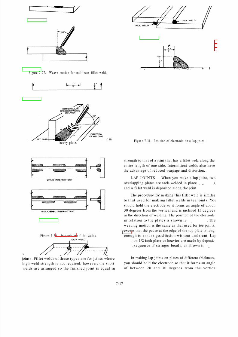
8/8/2019 Steelworker Vol. 1 -14250
http://slidepdf.com/reader/full/steelworker-vol-1-14250 149/246
Figure 7-27.—Weave motion for multipass f i l let weld.
Figur e 7-28.—Order of making s t r ing beads for a tee jo in t inheavy p la te .
Figure 7-29.—Intermi t ten t f i l l e t welds .
Chain-intermittent or staggered-intermittent fillet
welds, as shown in figure 7-29, are used on long tee
joint s. Fillet welds of th ese types ar e for joints where
high weld strength is not required; however, the short
welds are arranged so the finished joint is equal in
Figure 7-30.—Tack weld ing a lap jo in t .
Figur e 7-31.—Posi t ion of e lect rode on a lap jo in t .
str ength to tha t of a joint t hat has a fillet weld along the
entire length of one side. Intermittent welds also have
the advantage of reduced warpage and distortion.
LAP J OINTS.— When you make a lap joint, twooverlapping plates are tack-welded in place (fig. 7-30),
and a fillet weld is deposited along th e joint.
The procedure for m aking t his fillet weld is similar
to th at used for mak ing fillet welds in tee joint s. You
should hold the electrode so it forms an angle of about
30 degrees from the vertical and is inclined 15 degrees
in the direction of welding. The position of the electrode
in relation to the plates is shown in figur e 7-31. Th e
weaving motion is the same as that used for tee joints,
except that the pause at the edge of the top plate is long
enough to ensur e good fusion without un dercut. Lap joint s on 1/2-inch plate or heavier ar e ma de by deposit-
ing a sequen ce of stringer bead s, as sh own in figure
7-31,
In making lap joints on plates of different thickness,
you should hold the electrode so that it forms an angle
of between 20 and 30 degrees from the vertical
7-17

8/8/2019 Steelworker Vol. 1 -14250
http://slidepdf.com/reader/full/steelworker-vol-1-14250 150/246
Figure 7-32.—Lap jo in ts on p la tes of d i f fe ren t th ickness .
Figu re 7-33.—H or izon ta l bu t t j o in t .
F igu re 7-34.—M ul t ip l e pas ses .
Figure 7-35.—Ver t ica l weld p la te p os i t ions .
(fig. 7-32). Be careful not to overheat or undercut the
thinner plate edge.
BUTT J OINTS.— Most butt joints, designed for
horizontal welding, have the beveled plate positioned on
the top. The plate that is not beveled is on the bottom
and the flat edge of this plate provides a shelf for the
molten metal so that it does not run out of the joint (fig.
7-33). Often both edges are beveled to forma 60-degree
included a ngle. When th is type of joint is used, m ore
skill is required because you do not have the retaining
shelf to hold the molten puddle.
The number of passes required for a joint depends
on the diameter of the electrode and t he th ickness of the
metal. When multiple passes are required (fig. 7-34),
place the first bead d eep in th e root of the joint. The
electr ode holder sh ould be inclined a bout 5 degrees
downward. Clean and remove all slag before applying
each following bead. The second bead should be placed
with t he electrode holder h eld about 10 degrees u pward.
For the third pass, hold the electrode holder 10 to 15degrees downwar d from t he h orizont al. Use a slight
weaving motion and ensure that each bead penetrates
the base metal.
VERTICAL-P OSITION WELDING
A “vertical weld” is defined as a weld that is applied
to a vertical surface or one that is inclined 45 degrees or
less (fig. 7-35). Erecting structures, such as buildings,
pontoons, tanks, and pipelines, require welding in this
position. Welding on a vertical surface is much more
difficult than welding in the flat or horizontal positiondue to the force of gravity. Gravity pulls the molten
metal down. To counteract this force, you should use
fast-freeze or fill-freeze electrodes.
Vertical welding is done in either an upward or
downward position. The terms used for the direction of
welding are vertical u p or vertical d own. Vertical down
welding is suited for welding light gauge metal because
the penetra tion is shallow and diminishes the possibility
of burning through the metal. Furthermore, vertical
down welding is faster which is very important in pro-
duction work.
Cur ren t Se t t ings and E lec t rode Movem ent
In vertical arc welding, the curr ent settings should
be less than those used for t he sam e electr ode in the flat
position. Another difference is that the current used for
welding upward on a vertical plate is slightly higher tha n
the current used for welding downward on the same
plate.
7-18

8/8/2019 Steelworker Vol. 1 -14250
http://slidepdf.com/reader/full/steelworker-vol-1-14250 151/246
Figure 7-36.—Bead weld ing in the ver t ica l pos i t ion .
To produce good welds, you must maintain the
proper angle between the electrode and the base metal.
In welding upward, you should hold the electrode at 90
degrees to the vertical, as shown in figure 7-36, view A.
When weaving is necessary, oscillate the electrode, as
shown in figure 7-36, view B.
In vert ical down welding, incline th e outer en d of
the electrode downward about 15 degrees from the
horizont al while keeping th e arc pointin g upward t o-
ward t he deposited molten m etal (figure 7-36, view C).
When vert ical down welding requires a weave bead, you
should oscillate the electrode, as shown in figure 7-36,
view D.
J o in t Type
Vertical welding is used on most types of joints. The
types of joints you will most often use it on are tee joints,
lap joints, and butt joints.
When making fillet welds in either tee or lap joints
in the vertical position, hold the electrode at 90 degrees
to the plates or not more than 15 degrees off the hori-
zont al for pr oper molten meta l contr ol. Keep th e ar c
short to obtain good fusion and penetration.
T E E J O IN T S.— To weld tee joints in the vertical
position, start the joint at the bottom and weld upward.
7-19

8/8/2019 Steelworker Vol. 1 -14250
http://slidepdf.com/reader/full/steelworker-vol-1-14250 152/246
Figure 7-37.—Fi l le t welds in th e ver t ica l pos i t ion .
Move the electrode in a triangular weaving motion, as
shown in figure 7-37, view A. A slight pause in the
weave, at the points indicated, improves the sidewall
penetration and provides good fusion at the root of the joint.
When the weld metal overheats, you should quickly
shift the electrode away from the crater without break-
ing the ar c, as sh own in figur e 7-37, view B. This permits
the molten metal to solidify without running downward.
Return the electrode immediately to the crater of the
weld in order to maint ain t he desired size of the weld.
When more than one pass is necessary to make a tee
weld, you may use either of the weaving motions shown
in figure 7-37, views C and D. A slight pause at the end
of the weave will ensur e fusion without undercutt ing theedges of the plates.
LAP J OINTS.— To make welds on lap joints in the
vertical position, you sh ould move the electr ode in a
triangular weaving motion, as shown in figur e 7-37,
view E. Use the same procedure, as outlined above for
the tee joint, except direct th e electr ode more toward the
vertical plate mar ked “G.” Hold the ar c short, and pause
7-20

8/8/2019 Steelworker Vol. 1 -14250
http://slidepdf.com/reader/full/steelworker-vol-1-14250 153/246
Figure 7-38.—Butt joint welding in the ver t ical posi t ion.
slightly at the surface of plate G. Try not to undercut
either of the plates or to allow the molten metal to
overlap at the edges of the weave.
Lap joints on heavier plate m ay require more th anone bead. If it does, clean the initial bead t horoughly and
place all subsequent beads as shown in figure 7-37, view
F. The precautions to ensure good fusion and uniform
weld deposits that was previously outlined for tee joints
also apply to lap joints.
BUTT J OINTS.— Prepare th e plates used in verti-
cal welding identically to those prepared for welding in
the flat position. To obtain good fusion and penetration
with no undercutting, you should hold a short arc and
the motion of the arc should be carefully controlled.
Butt joints on beveled plates 1/4 inch thick can be
welded in one pass by using a triangular weave motion,
as shown in figure 7-38, view A.
Welds made on 1/2-inch plate or heavier should be
done in several passes, as shown in figure 7-38, view B.
Deposit t he last pass with a semicircular weaving mo-
tion with a slight “whip-up” and pause of the electrode
at the edge of the bead. This produces a good cover pass
with no undercutt ing. Welds made on plates with a
backup str ip should be done in th e same ma nner.
E-7018 Electrode Welding Technique
The previously described vertical welding tech-
niques generally cover all types of electrodes; however,
you should modify the procedure slightly when using
E-7018 electrodes.
When vertical down welding, you should drag the
electr ode lightly using a very short ar c. Refra in from
using a long arc since the weld depends on the molten
slag for shielding. Small weaves and stringer beads are
preferred to wide weave passes. Use higher amperage
with ac tha n with dc. Point the electrode stra ight into the
joint and tip it forward only a few degrees in the direc-
tion of travel.
On vertical up welding, a triangular weave motion
produces the best results. Do not use a whipping motion
or remove the electrode from the molten puddle. Point
the electrode straight into the joint and slightly upward
in order to allow the arc force to help control the puddle.
Adjust t he a mper age in th e lower level of th e recom-
mended range.
OVERHEAD-POSITION WELDING
Overhead welding is the most difficult position in
welding. Not only do you have to contend with the force
of gravity but the majority of the time you also have to
assume an awkward stance. Nevertheless, with practice
it is possible to make welds equal to those made in the
other positions.
Curr en t Se t t i ngs and E lect rode Movemen t
To retain complete control of the molten puddle, use
a very short ar c and reduce the ampera ge as recom-
mended. As in the vertical position of welding, gravity
causes the molten metal to drop or sag from the plate.
When too long an arc is held, the transfer of metal from
th e electr ode to the base m eta l becomes increa singly
difficult, an d t he chan ces of large globules of molten
metal dropping from the electrode increase. When you
routinely shorten and lengthen the arc, the dr opping of
molten metal can be prevented; however, you will defeat
your purpose should you carry too large a pool of molten
metal in the weld.
One of the problems encountered in overhead weld-
ing is the weight of the cable. To reduce arm and wrist
fatigue, drape the cable over your shoulder when weld-
ing in the standing position. When sitting, place the
7-21
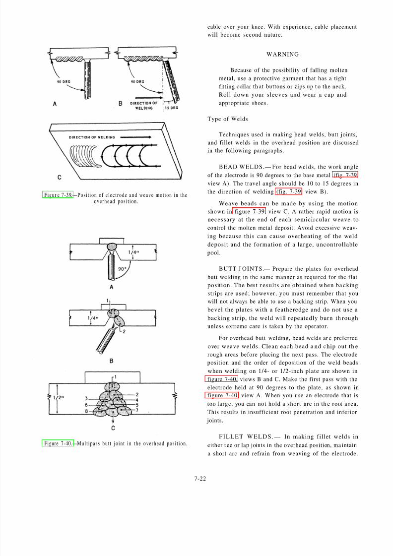
8/8/2019 Steelworker Vol. 1 -14250
http://slidepdf.com/reader/full/steelworker-vol-1-14250 154/246
Figur e 7-39.—Posi t ion of e lec t rode and weave mot ion in theoverhead pos i t ion .
Figure 7-40.—Mult ipass but t jo in t in the overhead pos i t ion .
cable over your knee. With experience, cable placement
will become second nature.
WARNING
Because of the possibility of falling molten
metal, use a protective garment that has a tight
fitting collar th at buttons or zips up t o the neck.
Roll down your sleeves and wear a cap andappropriate shoes.
Type of Welds
Techniques used in making bead welds, butt joints,
and fillet welds in the overhead position are discussed
in the following paragraphs.
BEAD WELDS.— For bead welds, the work angle
of the electrode is 90 degrees to the base metal (fig. 7-39,
view A). The travel angle should be 10 to 15 degrees in
the direction of welding (fig. 7-39, view B).Weave beads can be made by using the motion
shown in figure 7-39, view C. A rather rapid motion is
necessary at the end of each semicircular weave to
control the molten metal deposit. Avoid excessive weav-
ing because this can cause overheating of the weld
deposit and the formation of a large, uncontrollable
pool.
BUTT J OINTS.— Prepare the plates for overhead
butt welding in the same manner as required for the flat
position. The best r esults a re obtained when ba cking
strips are used; however, you must remember that youwill not always be able to use a backing strip. When you
bevel the plates with a featheredge and do not use a
backing strip, the weld will repeatedly burn th rough
unless extreme care is taken by the operator.
For overhead butt welding, bead welds ar e preferred
over weave welds. Clean each bead a nd chip out th e
rough areas before placing the next pass. The electrode
position and the order of deposition of the weld beads
when welding on 1/4- or 1/2-inch plate are shown in
figure 7-40, views B and C. Make the first pass with the
electrode held at 90 degrees to the plate, as shown infigure 7-40, view A. When you use an electrode that is
too large, you can not hold a short arc in th e root a rea.
This results in insufficient root penetration and inferior
joints.
FILLET WELDS.— In making fillet welds in
either t ee or lap joints in the overhead position, ma intain
a short arc and refrain from weaving of the electrode.
7-22

8/8/2019 Steelworker Vol. 1 -14250
http://slidepdf.com/reader/full/steelworker-vol-1-14250 155/246
Figure 7-41.—Fi l le t weld ing in the overhead pos i t ion .
Hold the electrode at approximately 30 degrees to the the arc and allow the metal to solidify. Immediately
vertical plate and move it uniformly in the direction of return the electrode to the crater and continue welding.
welding, as shown in figure 7-41, view B. Cont rol th eOverhead fillet welds for either tee or lap joints on
heavy plate require several passes or beads to completear c motion to secure good penetr at ion in th e root of the
the joint. One example of an order of bead deposition isweld and good fusion with the sidewalls of the vertical
shown in figure 7-41, view A. The root pass is a stringand horizontal plates. When the molten metal becomes bead made with no weaving motion of the electrode. Tilt
too fluid an d ten ds t o sag, whip the electrode quickly the electrode about
away from the crater and ahead of the weld to lengthen welding, as shown in
7-23
15 degrees in the direction of
figure 7-41, view C, and with a

8/8/2019 Steelworker Vol. 1 -14250
http://slidepdf.com/reader/full/steelworker-vol-1-14250 156/246
Table 7-3—Causes and Cures of Common Welding Problems
7-24

8/8/2019 Steelworker Vol. 1 -14250
http://slidepdf.com/reader/full/steelworker-vol-1-14250 157/246
slight circular motion make the second, third, and fourth
passes. This motion of the electrode permits greater
control and better distribution of the weld metal.
Remove all slag and oxides from the surface of each pass
by chipping or wire brushing before applying additional
beads to the joint.
WELDING DIFFICULTIES
Many of the welding difficulties in metal-arc weld-
ing are the same as in oxygas welding. A few such
problems include undercut, cracked welds, poor fusion,
and incomplete penetration.
Table 7-3 provides an illustration of the most com-
mon welding problems encountered during the arc-
welding process and methods to correct them.
Every welder has the responsibility of making each
weld the best one possible. You can produce quality
welds by adhering to the rules that follow.
1. Use only high-quality welding machines,
electrodes, and welding accessories.
2. Know the base mat erial tha t you are working
on.
3. Select the proper welding process that gives the
highest quality welds for t he base ma terial used.
4. Select the proper welding procedure that meets
the service requirement of the finished weldment.
5. Select the correct electrode for the job in
question.
6. When preheating is specified or required make
sure you meet the temperature requirements. In any
case, do not weld on material that is below 32°F without
first preheating.
7. Clean the base metal of all slag, paint, grease,
oil, moisture, or any other foreign materials.
8. Remove weld slag and th orough ly clean ea ch
bead before making th e next bead or pass.
9. Do not weld over cracks or porous ta ck welds.
Remove defective tack welds before welding.
10. Be particularly alert to obtain root fusion on the
first pass of fillet and groove welds.
11. When groove weld root gaps are excessive,
build up one side of the joint before welding the pieces
together.
12. When fillet weld root gaps are excessive, be
sur e you increa se th e size of the fillet weld t o the size of
the root gap to maintain the strength requirement. In
some cases, it is advantageous to make a groove weld l
to avoid extremely large fillet welds.
13. Inspect your work after completion and
immediately remove and replace any defective weld.
14. Observe the size requirement for each weld and
make sure that you meet or slightly exceed the specified
size.
15. Make sure that the finished appearance of the
weld is smooth and that overlaps and undercuts have
been repaired.
P IP E W E L D IN G
Welding is the simplest and easiest way to join
sections of pipe. The need for complicated joint designs
and special threading equipment is eliminated. Welded
pipe has reduced flow restrictions compared to me-
chanical connections and the overall installation costs
are less. The most popular method for welding pipe isthe shielded metal-arc process; however, gas shielded
arc methods have made big inroads as a result of new
advances in welding technology.
Pipe welding ha s become r ecognized as a profes-
sion in itself. Even though many of the skills are com-
parable to other types of welding, pipe welders develop
skills that are unique only to pipe welding. Because of
the h azardous mat erials that most pipelines carr y, pipe
welders are required to pass specific tests before they
can be certified
In the following paragraphs, pipe welding positions,
pipe welding procedures, definitions, and related infor-
mation are discussed.
P IP E W E L D IN G P O S IT IO N S
You may recall from chapter 3 of this manual that
th ere a re four positions us ed in pipe welding (fig. 3-30).
They are known as the horizontal rolled position (1G),
the horizontal fixed position (5G), pipe inclined fixed
(6G), an d th e vertical position (2G). Remember : th ese
terms refer to the position of the pipe and n ot to the weld
P IP E W E L D IN G P R O C E D U R E S
Welds that you cannot make in a single pass should
be made in interlocked multiple layers, not less than one
layer for each 1/8 inch of pipe th icknes s. Deposit each
layer with a weaving or oscillating motion. To prevent
entrapping slag in the weld metal, you should clean each
layer thoroughly before depositing the next layer.
7-25

8/8/2019 Steelworker Vol. 1 -14250
http://slidepdf.com/reader/full/steelworker-vol-1-14250 158/246
Figur e 7-42.—But t jo in ts a nd socket f i t t ing jo in ts .
Butt joints are commonly used between pipes and
between pipes and welded fittings. They are also used
for butt welding of flanges and welding stubs. In making
a butt joint, place two pieces of pipe end to end, align
them, and then weld them. (See fig. 7-42.)
When t he wa ll thickness of the pipe is 3/4 inch orless, you can use either the single V or single U type of
butt joint; however, when th e wall thickness is more th an
3/4 inch, only the single U type should be used.
Fillet welds are used for welding slip-on and
threaded flanges to pipe. Depending on the flange and
type of service, fillet welds may be required on both
sides of the flange or in combination with a bevel weld
(fig. 7-43). Fillet welds are also used in welding screw
or socket couplings to pipe, using a single fillet weld
(fig. 7-42). Sometimes flanges require alignment. Fig-
u re 7-44 shows one t ype of flange squar e an d its u se in
vertical and horizontal alignment.
Another form of fillet weld used in pipe fitting is a
seal weld A seal weld is used primar ily to obtain tight-
ness and prevent leakage. Seal welds should not be
considered as adding strength to the joint.
Figure 7-43.—Flange connect ions .
Figure 7-44.—Flange a l ignment .
J OINT PR EP ARATION AND FIT-UP
You must carefully prepare pipe joints for welding
if you want good results. Clean the weld edges or
surfaces of all loose scale, slag, rust, paint, oil, and other
foreign matter. Ensure that the joint surfaces are smooth
an d u niform . Remove th e slag from flam e-cut edges;
however, it is not necessary to remove the temper color.
When you prepa re joint s for welding, remember
tha t bevels must be cut a ccura tely. Bevels can be made
by machining, grinding, or u sing a gas cutting t orch. In
fieldwork, the welding operator usua lly must mak e thebevel cuts with a gas torch. When you are beveling, cut
away a s little m eta l as possible to allow for complete
fusion and penetration. Proper beveling reduces the
amount of filler m etal r equired which, in t urn , reduces
time an d expense. In addition, it also means less str ain
in th e weld and a better job of design an d welding.
7-26

8/8/2019 Steelworker Vol. 1 -14250
http://slidepdf.com/reader/full/steelworker-vol-1-14250 159/246
Figu re 7-45 .—Angle i ron j ig .
Align the piping before welding and maintain it in
alignment during the welding operation. The maximum
alignment tolerance is 20 percent of the pipe thickness.
To ensure proper initial alignment, you should use
clamps or jigs as holding devices. Apiece of angle iron
makes a good jig for a small-diameter pipe (fig. 7-45),
while a section of channel or I-beam is more suitable for
larger diameter pipe.
TACK WELDI NG
When welding material solidly, you may use tack
welds to hold it in place temporarily. Tack welding is
one of the most important steps in pipe welding or any
other type of welding. The number of tack welds re-
quired depends upon the diameter of the pipe. For
1/2-inch pipe, you need two tacks; place them directly
opposite each other. As a rule, four tacks are adequate
for standard size of pipe. The size of a tack weld is
determined by the wall thickness of the pipe. Be sure
that a tack weld is not more than twice the pipe thickness
in length or two thirds of the pipe thickness in depth.
Tack welds should be the s ame qua lity as th e final weld.Ensu re th at t he ta ck welds have good fusion a nd a re
thoroughly cleaned before proceeding with the weld.
SPACERS
In a ddition to tack welds, spacers sometimes ar e
required to maintain proper joint alignment. Spacers are
accurately machined pieces of metal that conform to the
dimensions of the joint design used. Spacers are some-
times referred t o as chill rings or backing rings, and th ey
serve a number of purposes. They provide a means for
maintaining the specified root opening, provide a con-
venient location for tack welds, and aid in the pipe
alignment. In addition, spacers can prevent weld spatter
an d t he format ion of slag or icicles inside th e pipe.
E L E C T R O D E S E L E C T IO N
Select the electrode that is best suited for the posi-
tion and type of welding to be done. For the root pass of
a multilayer weld, you need an electrode large enough,
yet not exceeding 3/16 inch, that ensures complete
fusion and penetration without undercutting and slag
inclusions.
Make certain the welding current is within the range
recommended by the manufacturers of the welding
machines and electrodes.
WEATHER CONDITIONS
Do not as sign a welder t o a job un der a ny of th e
following conditions listed below unless the welder and
the work area are properly protected:
c When the atmospheric temperature is less than
0°F
l When the surfaces are wet
l When rain or snow is falling, or moisture is
condensing on the weld surfaces
l Dur ing periods of high wind
At temperatures between 0°F and 32°F, heat the
weld area within 3 inches of the joint with a torch to atemperature warm to the hand before beginning to weld.
WEARFACING
The Seabee welder can greatly extend the life of
construction equipment by the use of wearfacing proce-
dures. Wearfacing is the process of applying a layer of
special composition metal onto the surface of another
type of metal for the purpose of reducing wear. The
selection of a wearfacing alloy for application is based
on the ability of the alloy to withstand impact or abra-
sion. Impact refers to a blow or series of blows to a
surface that results in fracture or gradual deterioration.
Abrasion is the grinding action that results when one
surface slides, rolls, or rubs against another. Under
high-compressive loads, this action can result in goug-
ing.
Alloys that are abrasion resistant are poor in with-
standing impact. Conversely, those that withstand im-
pact well are poor in resisting abrasion; however, there
are many alloys whose wearfacing properties fall be-
tween the two extremes. These alloys offer some pro-
tection against abrasion and withstand impact well.
WORKPIECE PREPARATION
Before you wear-face a workpiece, all dirt, oil, rust,
grease, and other foreign mat ter must be removed. If you
do not, your finished product will be porous and subject
to spalling. You also need a solid foundation; therefore,
repair all cracks and remove any metal tha t is fatigued
or rolled over.
7-27

8/8/2019 Steelworker Vol. 1 -14250
http://slidepdf.com/reader/full/steelworker-vol-1-14250 160/246
F igure 7-46 .—Wear fac ing t echn iques .
P REH EA TI N G
Depending on t he t ype of metal, sometimes it is
necessary to preheat the base metal to lessen distortion,
to prevent spa lling or cracking, and t o avoid ther mal
shock The preheating temperature depends on the car-
bon a nd a lloy conten t of the base m etal. In genera l, as
carbon content increases so does the preheating tem-
perature. Improper heating can adversely affect a metal
by reducing its resistance to wear, by making it hard and
brittle, or by making it m ore prone to oxidation a nd
scaling.
To preheat properly, you must know the composi-
tion of the base metal. A magnet can be used to deter-
mine if you are working with carbon steel or austenitic
manganese steel. Carbon steel is magnetic, but be care-
ful because work-hardened austenitic manganese steel
is also magnetic. Make sur e tha t you check for m agnet-
ism in a nonworked part of the austenitic manganese
steel. There are other ways to tell the difference between
meta ls, such a s cast iron an d cast st eel. Cast iron chips
or cracks, while cast steel shaves. Also, some metals
give off telltale sparks when struck by a chisel.
In prehea ting, you should raise the su rface tempera-
tur e of the workpiece to the desired point a nd t hen soak
it until the heat reaches its core. After wearfacing, cool
the work places slowly.
TECH N I Q U ES
Where possible, position the workpiece for down-
hand welding. This allows you to finish the job quicker
and at less cost.
The building up and wearfacing of cast iron is not
generally recommended because cast iron tends to
crack. However, some cast-iron parts that are subject to
str aight abr asion can be wear faced successfully. You
must preheat these parts to temperatures of 1000°F to1200°F and then allow them to cool slowly after wear-
facing. Peening deposits on cast iron helps to relieve
stresses after welding.
Welding materials for building up worn parts differ
from those used in wearfacing the same parts. Before
wearfacing a badly worn part, you must first build it up
to 3/16 to 3/8 of an inch of its finished size. The buildup
material must be compatible with both the base metal
and the wearfacing overlay as well as being strong
enough t o meet the str uctural r equirements. Also, they
must have the properties that enable them to resist cold
flowing, mushing under high-compressive loads, and
plastic deformation under heavy impact. Without these
properties, the buildup mat erials can not support the
wearfacing overlay. When the overlay is not properly
supported, it will span.
Many t imes high-alloy wearfacing ma terials a re
deposited on the parts before they are placed in service.
The maximum allowable wear is usually no more than
two layers deep (1/4 inch) before wearfacing. Try to
deposit the wearfacing alloy in layers that are not too
thick. Thick layers creates more problems than no over-
lay at all. Usually you only need two layers. The frost
layer produces an admixture with the base metal; the
second forms a wear-resistant surface.
In wearfacing built-up carbon-steel parts, maintain
high interpass temperatures and use a weaving bead,
rat her t han a st ringer bead. (See fig. 7-46.) Limit the thick-
ness of a single pass bead t o 3/16 inch. Use the s ame
technique for each layer and avoid severe quenching.
Deposits made with
check on the surface.
high-alloy
Checking
electrodes should
reduces residual
Figure 7-47.—Compar ison be tween cross -checking and cracking .
7-28

8/8/2019 Steelworker Vol. 1 -14250
http://slidepdf.com/reader/full/steelworker-vol-1-14250 161/246
Figu re 7-48.—Wear fac ing bu l ldoze r end b i t s .
F igu re 7-49.—Wear fac ing shove l t ee th .
F igu re 7-50.—W aff le o r c ros sha t ch ing .
(locked-in) stress es. Without checking, th e combination
of residual st resses a nd ser vice str esses ma y exceed
tensile strength and cause deep cracks or spal l ing (fig.
7-47). Be sur e to indu ce checking if it does not occur
naturally or if it is unlikely to occur, as in large parts
where h eat builds up. You can bring on checking by
sponging the deposit with a wet cloth or by spraying it
with a fine m ist of wat er. Also you can speed u p check-
ing by occasionally striking it with a hammer while it is
cooling. When a check-free dep osit is requ ired, us e a
softer alloy and adjust preheating and postheating re-
quirements.
Bulldozer Blades
Bulldozer blades are wear-faced by placing the end
bits in th e flat position a nd welding beads across th e
outer corner s and along the edges. Be sure t o preheat th e
high-carbon blades before wearfacing. On worn end
bits, weld new corners and then wear-face (fig. 7-48).
S h o v e l t e e t h
Wear-face shovel teeth when they are new and
before being placed into service. The weld bead pattern
used in wearfacing can have a marked effect on the
service life of the teeth. Wear-face shovel teeth that work
mainly in rock with beads running the length of eachtooth (fig. 7-49). This allows the rock to ride on the hard
metal beads. Teeth that are primarily used to work in
dirt, clay, or sand should be wear-faced with beads
running across the width of each tooth, perpendicular to
the direction of the material that flows past the teeth.
(See fig. 7-49.) This allows the material to fill the spaces
between the beads and provide more protection to the
base m etal. Another effective pat tern is th e waffle or
crosshatch (fig. 7-50). The wearfacing is laid on the top
and sides of each tooth, 2 inches from its point. Stringer
beads behind a solid deposit reduce wash (fig. 7-51).
Figur e 7-51.—Compar ison of wear fac ing pa t te rns for shovel tee th .
7-29

8/8/2019 Steelworker Vol. 1 -14250
http://slidepdf.com/reader/full/steelworker-vol-1-14250 162/246
Table 7-4.—Table of Recommended Elect rode Sizes, Current Set t ings, and Cut t ing Speeds for Carbon-Arc Cut t ing Different Thicknessesof S tee l P la te
More information on wearfacing applications may The carbon-arc method of cutting is successful on
be obta ined from t he NCF Welding M aterials Hand -
book, NAVFAC P-433.
CARBON-ARC CUT TING
Metals can be cut cleanly with a carbon electrode
arc because no foreign metals are introduced at the arc.
The cutting current should be 25 to 50 amps above the
welding current for the same thickness of metal.
The carbon electrode point should be ground so that
it is very sharp. During th e actual cuttin g, move the
carbon electr ode in a vertical elliptical m ovement to
undercut t he meta l; this aids in the r emoval of the m olten
metal. As in oxygen cutting, a crescent motion is pre-
ferred. Figure 7-52 shows the relative positions of the
electrode and the work in the cutting of cast iron.
cast iron because the arc temperature is high enough to
melt t he oxides form ed. It is especially import ant toundercut the cast-iron kerf to produce an even cut.
Position the electrode so the molten metal flows away
from t he gouge or cutt ing area s. Table 7-4 is a list of
cutting speeds, plate thicknesses, and current settings
for carbon-arc cutting.
Because of the high currents required, the graphite
form of carbon electrode is better. To reduce the heating
effect on the electrode, you should not let it extend more
tha n 6 inches beyond the holder when cutting. If th e
carbon burns away too fast, shorten the length that it
extends out of the electrode holder to as little as 3 inches.
Operating a carbon electrode at extremely high t empera-
tur es causes its sur face to oxidize and bur n awa y, result-
ing in a rapid reduction in the electrode diameter.
Carbon-arc cutting does not require special gener-
ators. Standard arc-welding generators and other items
of arc-welding station equipment are suitable for use.
Straight polarity direct current (DCSP) is always used.
Because of the high temperature and the intensity
of the a rc, choose a sh ade of helmet lens th at is darker
tha n t he norma l shade you would use for welding on t he
same thickness of meta l. A num ber 12 or 14 lens sh ade
is recommended for carbon-arc welding or cutting.
AIR CARBON-ARC CUTTING
Air carbon-arc cutting (ACC) is a process of cutting,
piercing, or gouging metal by heating it to a molten stateFigure 7-52.—Carbon-arc cu t t ing on cas t i ron . and then using compressed air to blow away the molten
7-30

8/8/2019 Steelworker Vol. 1 -14250
http://slidepdf.com/reader/full/steelworker-vol-1-14250 163/246
Figu re 7-53.—Air ca r bon-a rc cu t t i ng .
metal. Figure 7-53 shows the process. The equipment
consists of a special holder, as shown in figure 7-54, that
uses carbon or graphite electrodes and compressed air
fed through jets built into the electrode holder. A push
button or a hand valve on the electrode holder controls
the air jet.
The air jet blows the m olten m etal away a nd usu ally
leaves a surface that needs no further preparation for
welding. The electrode holder operates at air pressures
varying between 60 an d 100 psig.
During use, bare carbon or graphite electrodes be-
come smaller due to oxidation caused by heat buildup.
Copper coating these electrodes reduces the heat
buildup and prolong their use.
The operating procedures for air carbon-arc cutting
and gouging are basically the same. The procedures are
as follows:
l
l
l
l
l
Adjust the machine to the correct current for
electrode diameter.
Start the air compressor and adjust the regulator
to the corr ect a ir pressu re. Use the lowest a ir
pressure possible-just enough pressure to blow
away the molten metal.
Insert the electrode in the holder. Extend the
carbon electrode 6 inches beyond the holder.
Ensure that the electrode point is properly
shaped .
Strike the arc; then open the air-jet valve. The
air-jet disc can swivel, and the V-groove in the
disc automatically aligns the air jets along the
electrode. The electrode is adjusted relative to the
holder.
Control the arc and the speed of travel according
to the shape and the condition of the cut desired.
Figure 7-54.—Air carbon-arc e lec t rode holder wi th carbon e lec t rode ins ta l led .
7-31

8/8/2019 Steelworker Vol. 1 -14250
http://slidepdf.com/reader/full/steelworker-vol-1-14250 164/246
Figure 7-56.—Stee l e l ec t rode be ing used to cu t p la te .
Figure 7-55.—V-groove gouged in 2-inch-thick carbon steel .
METAL ELECTRODE ARC CUTTING
. Always cut away from the operator as molten
metal sprays some distance from the cutting ac-
tion. You ma y use th is process to cut or gouge
metal in the flat, horizontal, vertical, or overhead
positions.
AIR CARBON-ARC GOUGING
Air carbon-ar c gouging is u seful in ma ny var iousmetalworking applications, such as metal shaping and
other welding preparations. For gouging, hold the elec-
trode holder so the electrode slopes back from the direc-
tion of tr avel. The air blast is directed along the electrode
toward the arc. The depth and contour of the groove are
contr olled by the electr ode angle and tr avel speed. The
width of the groove is governed by the diameter of the
electrode.
When cut ting or gouging a sha llow groove on th e
surface of a piece of metal, you should position the
electrode holder at a very flat angle in relation to the
work. The speed of travel and the current setting also
affect the depth of the groove. The slower the movement
and the higher the current, the deeper the groove. An
example of a V-groove cut made in a 2-inch-thick mild
steel plate by a machine guided carbon-arc air-jet is
shown in figure 7-55.
Metal can be removed with the standard electric arc,
but for good gouging or cutting results, you should use
special metal electrodes that have been designed for this
type of work, Manufacturers have developed electrodes
with special coatings that intensify the arc stream for
rapid cutting. The covering disintegrates at a slower rate
than the metallic center. This creates a deep recess that
produces a jet action tha t blows th e molten m etal awa y
(fig. 7-56). The main disadvantage of these electrodesis that the additional metal produced must be removed.
These electrodes are designed for cutting stainless
steel, copper, aluminum, bronze, nickel, cast iron, man-
ganese, steel, or alloy steels.
Atypical gouge-cutting operation is shown in figure
7-57. Notice that the angle between the electrode and
plate is sm all (5 degrees or less). This makes it easy to
remove the extra meta l produced by th e electr ode.
The recommended current setting is as high as the
electrode will take without becoming overheated to the
point of cracking the covering. For 1/8-inch electrodes,
the setting ranges between 125 and 300 amperes; for
5/32-inch electr odes, th e sett ing ra nges between 250 an d
375 amperes; and for 3/16-inch electrodes, the setting
ranges between 300 and 450 amperes. Use a very short
arc, and when cutting takes place underwater, the coat-
ing must be waterpr oof.
7-32

8/8/2019 Steelworker Vol. 1 -14250
http://slidepdf.com/reader/full/steelworker-vol-1-14250 165/246
Figure 7-57.—Gouge-cut t ing opera t ion us ing a so l id core a rc-cu t t ing e lec t rode .
WELDING QUALITY CONTROL
In the fabrication or repair of equipment, tests are
used to determine th e quality and soundness of the
welds. Many different tests have been designed for
specific faults. The type of test used depends upon therequirements of the welds and the availability of testing
equipment. In this section, nondestructive and destruc-
tive testing are briefly discussed.
NONDESTRUCTIVE TESTING
Nondestructive testing is a method of testing that
does not destroy or impair the usefulness of a welded
item. These tests disclose all of the common int erna l and
surface defects that can occur when improper welding
procedures are used. A large choice of testing devices is
available and most of them are easier to use than thedestructive methods, especially when working on large
and expensive items.
Visual In spection
Visual inspection is usually done automatically by
the welder as he completes his welds. This is strictly a
subjective type of inspection and usually there are no
definite or rigid limits of acceptability. The welder may
use templates for weld bead contour checks. Visual
inspections are basically a comparison of finished welds
with a n a ccepted st an dar d. This test is effective onlywhen t he visual qualities of a weld are th e most impor-
tant .
Magnet ic Par t ic le Inspect ion
Magnetic particle inspection is most effective for
the detection of surface or near surface flaws in welds.
Figure 7-58.—Circular magnet iza t ion (prod method) .
Figure 7-59.—Longi tudina l magnet iza t ion (co i l method) .
It is used in metals or alloys in which you can induce
magnetism. While the test piece is magnetized, a liquid
containing finely ground iron powder is applied. As long
as the magnetic field is not disturbed, the iron particles
will form a regular pat tern on the su rface of the test
piece. When the magnetic field is interrupted by a crack
or some other defect in the metal, the pattern of the
suspended ground metal also is interrupted. The parti-
cles of metal cluster around the defect, ma king it ea sy
to locate.
You can magnetize the test piece by either having
an electric current pass through it, as shown in figure
7-58, or by having an electr ic current pass t hrough a coil
of wire that surrounds the test piece, as shown in figure
7-59. When an electric current flows in a straight line
from one cont act point t o the other , magnet ic lines of
7-33

8/8/2019 Steelworker Vol. 1 -14250
http://slidepdf.com/reader/full/steelworker-vol-1-14250 166/246
force are in a circular direction, as shown in figure 7-58.
When the current flow is through a coil around the test
piece, as shown in figure 7-59, the magnetic lines of
force are longitudinal through the test piece.
When a defect is to show up as a disturbance in the
patt ern of the iron par ticles, the direction of the magnet ic
field must be at r ight an gles to th e major axis of the
defect. A magnetic field having the necessary direction
is established when the current flow is parallel to the
major axis of the defect. Since th e orienta tion of th e
defect is unknown, different current directions must be
used during the test. As shown in figure 7-58, circular
magnetism is induced in the test piece so you can inspect
the piece for lengthwise cracks, while longitudinal mag-
netism, as shown in figure 7-59, is induced so you can
inspect the piece for transverse cracks. In general, mag-
netic par ticle inspection is sa tisfactory for detecting
surface cracks an d subsurface cracks th at are n ot m ore
than 1/4 inch below the surface.
The type of magnetic particle inspection unit com-monly used in the Navy is a portable low-voltage unit
having a maximum magnetizing output of 1,000 am-
peres, either alternating or direct current. It is ready to
operate when plugged into the voltage supply specified
by the manufacturer. The unit consists of a magnetizing
current source, controls, metering, three 10-foot lengths
of flexible cable, and a prod kit. The prod kit includes
an insu lated prod grip fitted with an ON-OFF relay or
current control switch, a pair of heavy copper contact
prods, and two 5-foot lengths of flexible cable. Cable
fittings are designed so that either end of the cable can
be connected to the unit, to the prods, or to any other
cable. The three outlets on the front of the unit make
changing from alternating to direct current or vice versa
very easy. The outlets are labeled as follows: left is ac,
the center is COMMON, and the right is dc. One cable
will always be plugged into the COMMON outlet ,
while the other cable is plugged into either the ac or dc
outlet, depending upon what type of curr ent the t est
requires. For most work, alterna ting current magnetiza-
tion effectively locates fat igue cracks a nd similar de-
fects extending through to the surface. When you
require a more sensitive inspection to detect defects
below the surface, use direct current.
You can use the unit with alternating or direct
current in either of two ways: (1) with prods attached to
the flexible cable and used as contacts for the current to
pass into and out of a portion of the test piece, setting
up circular magnetization in the area between the prods
contact points, as shown in figure 7-58; or (2) with the
flexible cable wrapped around the work to form a coil
that induces longitudinal magnetism in the part of the
workpiece that is surrounded by the coiled cable
(fig. 7-59)0
Although you can use either of these two methods,
the prod method is probably the easier to apply. Inmost
instances, it effectively serves to detect surface defects.
With the prods, however, only a small area of the test
piece can be magnetized at any one time. This magnet-
ized area is limited to the distance between prod contact
points and a few inches on each side of the current path.
To check the entire surface, you must test each adjacent
ar ea by changing th e location of the pr od contact points.
Each area of the test piece must be inspected twice—
once with the current passing through the metal in one
direction an d then with the current passing through t he
meta l in a direction at right a ngles to the direction of the
first test. One of the advantages of the prod method is
that the current can be easily passed through the metal
in any desired direction. Thus, when a given area is
suspect, magnetic fields of different directions can be
induced during the test.
The prod method is accomplished by adjusting the
unit for a curr ent output s uitable for th e magnetizing and
testing of any particular kind of metal. The current
setting required depends on the distance between prod
conta ct points. With the pr od kit th at is supplied with th e
un it, the spa ce between pr od conta ct points is 4 to 6
inches. A current setting between 300 and 400 amperes
is satisfactory when th e mat erial thickness is less th an
3/4 inch. When the material thickness is over 3/4 inch,
use 400 to 600 amperes. When the prod contact points
ar e closer together , the sam e ma gnetic field force can beobtained with less current. With prods constantly at the
same spacing, more current will induce a greater field
strength.
After adjusting the unit, place the prods in position.
Hold them infirm contact with the m etal and tu rn on th e
curr ent. Then a pply magnetic part icles to the test area
with the duster bulb and look for any indicator patterns.
With th e cur ren t st ill on, remove the excess part icles
from the test area with a blower bulb and complete the
inspection. Do not move the prods un til after t he curr ent
has been tu rn ed off. To do so could cau se th e curren t t oarc, resulting in a flash similar to that occurr ing in arc
welding.
When you use magnetic particle inspection, hairline
cracks that are otherwise invisible are readily indicated
by an unmistakable outline of the defect. Large voids
beneath the surface are easier to detect than small voids,
but any defect below the surface is more difficult to
detect than one that extends through to the surface. Since
7-34

8/8/2019 Steelworker Vol. 1 -14250
http://slidepdf.com/reader/full/steelworker-vol-1-14250 167/246
false indications frequently occur, you must be able to
interpret the particle indications accurately.
The factors that help you interpret the test results
include the amount of magnetizing current applied, the
shape of the indication, the sharpness of the outline, the
width of the pattern, and the height or buildup of the
particles. Although these characteristics do not deter-
mine the seriousness of the fault, they do serve to
identify the kind of defect.
The indication of a crack is a sharp, well-defined
pattern of magnetic particles having a definite buildup.
This indication is pr oduced by a relat ively low-magnet-
izing curr ent. Seams ar e revealed by a straight, shar p,
fine in dicat ion. Th e buildup of par ticles is r elatively
weak, and the m agnetizing curr ent mu st be higher tha n
that required to detect cracks. Small porosity and
rounded indentations or similar defects are difficult to
detect for inexperienced inspectors. A high-magnetizing
current continuously applied is usually required. The
particle patterns for these defects are fuzzy in outline
and have a medium buildup.
The specifications governing the job determine
whether or not an indicated defect is to be chipped or
ground out and repaired by welding. Surface cracks are
always removed and repaired. Indications of subsurface
defects detected by magnetic particle inspection are
evaluated by the inspector. When the indication is posi-
tive, the standard policy is to grind or chip down to solid
metal an d mak e the r epair. Unless the inspector can
differentiate accurately between true and false indica-
tions, the use of magnetic particle inspection should berestricted to the detection of surface defects, for which
this application is almost foolproof.
After th e indicated defects have been r epaired, you
should reinspect the areas to ensure that the repair is
sound. The final step in magnetic particle inspection, is
to demagnetize the workpiece. This is especially impor-
tant when the workpiece is made of high-carbon steel.
Demagnetization is essential when you use direct cur-
rent to induce the magnetic field; however, it is not as
necessary when alternating current was used in the t est.
In fact, the usual demagnetization procedure involvesplacing the workpiece in an ac coil or solenoid and
slowly withdrawing it while current passes through the
coil.
Demagnetization can be accomplished with the
portable unit if a special demagnetizer is not available.
To demagnetize with t he porta ble unit, form a coil of
flexible cable around the workpiece. Ensure that
the cable is plugged into the unit for the delivery of
alternating current. Set the current regulator to deliver a
current identical to that used for the inspection and turn
on the unit. Gradually decrease the current until the
ammeter indicates zero. On large pieces, it may be
necessary to demagnetize a small portion of the work at
a time.
A check for the presence of a magnetic field may be
made by using a small compass. A deviation of the
needle from the normal position, when the compass is
held near the workpiece, is an indication tha t a magnetic
field is present. Also you can use an instrument called a
field indicator to check for the presence of a magnetic
field. This instrument usually comes with the magnetic
particle inspection unit e
Liqu id P ene t ran t In spect i on
Liquid penetrant methods are used to inspect metals
for surface defects that are similar to those revealed bymagnetic particle inspection. Unlike magnetic particle
inspection, which can reveal subsurface defects, liquid
penetrant inspection reveals only those defects that are
open to the surface.
Four groups of liquid penetrants are presently in
use. Group I is a dye penetra nt t hat is nonwater wash-
able. Group II is a water washable dye penetrant. Group
III and Group IV are fluorescent penetrants. Carefully
follow the instructions given for each type of penetrant
since there are some differences in the procedures and
safety precautions required for the various penetrants.
Before using a liquid penetrant to inspect a weld,
remove all slag, rust, paint, and moisture from the
surface. Except where a specific finish is required, it is
not necessary to grind the weld surface as long as the
weld surface meets applicable specifications. Ensure the
weld contour blends into the base metal without under-
cutting. When a specific finish is required, perform t he
liquid penetrant inspection before the finish is made.
This enables you to detect defects that extend beyond
the final dimensions, but you must make a final liquid
penetrant inspection after the specified finish has been
given.
Before using a liquid penetrant, clean the surface of
the material very carefully, including the areas next to
the inspection area. You can clean the surface by swab-
bing it with a clean, lint-free cloth saturated in a non-
volatile solvent or by dipping th e ent ire piece int o a
solvent. After the surface has been cleaned, remove all
tr aces of the cleaning ma terial. It is extremely import ant
to remove all dirt, grea se, scale, lint, salt s, or other
7-35

8/8/2019 Steelworker Vol. 1 -14250
http://slidepdf.com/reader/full/steelworker-vol-1-14250 168/246
Figure 7-60.—L i q u i d p e n e t r a n t i n s p e c t i o n .
mat erials and to make sure th at the sur face is entirely
dry before using the liquid penetrant.
Maintain the temperature of the inspection piece
and the liquid penetrant in the range of 50°F to 100°F.
Do not attempt to use the liquid penetrant when thistemperature range cannot be maintained. Do not use an
open flame to increase the temperature because some of
the liquid penetrant materials are flammable.
After thoroughly cleaning and drying the surface,
coat t he surface with t he liquid penetra nt. Spra y or bru sh
on the penetrant or dip the entire piece into the penetrant.
To allow time for t he penetr ant to soak into all th e cracks,
crevices, or other defects that are open to the surface,
keep the surface of the piece wet with the penetrant for
a min imum of 15 or 30 minu tes, depending upon th e
penetrant being used.
After keeping the surface wet with the penetrant for
the r equired length of time, remove any excess penetr ant
from the surface with a clean, dry cloth, or absorbent
paper towel. Then dampen a clean, lint-free material
with penetrant remover and wipe the remaining excess
penetrant from the test surface. Next, allow the test
surface to dry by normal evaporation or wipe it dry with
a clean, lint-free absorbent material. In drying the sur-
face, avoid contaminating it with oil, lint, dust, or other
materials that would interfere with the inspection.
After t he sur face has dr ied, apply another substa nce,
called a developer. Allow the developer (powder or
liquid) to stay on th e sur face for a minimum of 7 minut es
before star ting th e inspection. Leave it on no longer t han
30 minutes, thus allowing a total of 23 minutes to
evaluate t he r esults.
The following actions ta ke place when using dye
penetrants. First, the penetrant that is applied to the
surface of the material will seep into any passageway
open to the su rface, as sh own in figur e 7-60, view A.
The penetr ant is normally red in color, an d like penetr at-
ing oil, it seeps into any crack or crevice that is open to
the surface. Next, the excess penetrant is removed from
the surface of the metal with the penetrant remover and
a lint-free absorbent material. Only the penetrant on top
of the metal surface is removed (fig. 7-60, view B),
leaving the penetrant that has seeped into the defect.
Finally, the white developer is a pplied to th e sur face
of the metal, as shown in figure 7-60, view C. The
developer is an absorbing material that actually draws
the penetrant from the defect. Therefore, the red pene-
trant indications in the white developer represent the
defective areas. The a mount of red penetra nt drawnfrom the defective areas indicates the size and some-
times the type of defect. When you use dye penetrants,
the lighting in the test area must be bright enough to
enable you to see any indications of defects on the test
surface.
The indications you see during a liquid penetrant
inspection must be carefully interpreted and evaluated.
In almost every inspection, some insignificant indica-
tions are present. Most of these are the result of the
failure to remove all the excess penetrant from the
surface. At least 10 percent of all indications must beremoved from the surface to determine whether defects
are a ctua lly present or whether t he indications are t he
resu lt of excess penet ra nt . When a second ins pection
does not reveal indications in the same locations, it is
usually safe to assume that the first indications were
false.
7-36

8/8/2019 Steelworker Vol. 1 -14250
http://slidepdf.com/reader/full/steelworker-vol-1-14250 169/246
Remove all penetrant inspection materials as soon
as possible after t he final inspection has been m ade. Use
water or solvents, as appropriate. Since some of the
liquid penetrant materials are flammable, do not use
them near open flames, and do not apply them to any
surface that is at a temperature higher than 100°F. In
addition to being flammable, many solvents are poison-
ous in the vapor form and highly imitating to the skin in
the liquid form.
Radiographic Inspect ion
Radiographic inspection is a method of inspecting
weldments by the use of rays that penetrate through the
welds. X rays or gamma rays are the two types of waves
used for this process. The rays pass through the weld
and onto a sensitized film that is in direct contact with
th e back of the weld. When t he film is developed, gas
pockets, slag inclusions, cracks, or poor penetration will
be visible on the film.
Because of the danger of these rays, only qualified
personnel are authorized to perform these tests. As
Seabees, you will rarely come in contact with these
procedures.
Ult ra sonic In spect ion
Ultrasonic inspection of testing uses high-fre-
quency vibrations or waves to locate and measure de-
fects in welds. It can be used in both ferrous and
nonferrous materials. This is an extremely sensitive
system and can locate very fine surface and subsurface
cracks as well as other types of defects. All types of
joints can be t ested.This process uses high-frequency impulses to check
th e soundness of the weld. In a good weld, th e signal
travels through the weld to the other side and is then
reflected back and shown on a calibrated screen. Irregu-
larities, such as gas pockets or slag inclusions, cause the
signal t o reflect back sooner an d will be displayed on
the screen as a change in depth. When you use this
system, most all types of materials can be checked for
defects. Another advantage of this system is that only
one side of the weld needs to be exposed for testing.
Eddy Curren t Test i ng
Eddy curr ent is an other type of testing that u ses
electromagnetic energy to detect faults in weld deposits
and is effective for both ferrous an d nonferrous ma teri-
als. As a Seabee, you will rar ely use this t ype of testing
in the field.
Eddy current testing operates on the principle that
whenever a coil carrying a high-frequency alternating
current is placed next to a metal, an electrical current is
produced in th e meta l by induction. This induced current
is called an eddy current.
The test piece is exposed to electromagnetic energy
by being placed in or nea r h igh-frequency ac cur rent
coils. The differences in the weld cause changes in the
impedance of the coil, and this is indicated on electronic
instruments. When there are defects, they show up as a
change in impedance, and the size of the defect is shown
by the amount of this change.
DESTRUCTIVE TESTING
In destructive testing, sample portions of the welded
structures are required. These samples are subjected to
loads u nt il they actua lly fail. The failed pieces ar e th en
studied and compared to known standards to determine
the quality of the weld. The most common types of
destructive testing are known as free bend, guided bend,nick-break, impact, fillet welded joint, etching, a nd
tensile testing. The primary disadvantage of destructive
testing is that an actual section of a weldment must be
destroyed to evaluate the weld. This type of testing is
usua lly used in t he certificat ion process of the welder.
Some of the testing requires elaborate equipment
that is not available for use in the field. Three tests that
may be performed in the field without elaborate equip-
ment are the free-bend test, the guided-bend test, and the
nick-break test.
Fr ee-Bend Test
The FREE-BEND TEST is designed to measure the
ductility of the weld deposit and the heat-affected area
adjacent t o the weld. Also it is used t o determine t he
percentage of elongation of the weld metal. Ductility,
you sh ould recall, is th at property of a m etal t hat allows
it to be drawn out or hammered thin.
The first step in preparing a welded specimen for
the free-bend test is to machine the welded reinforce-
ment crown flush with th e sur face of the t est plate. Whenthe weld area of a test plate is machined, as is the case
of the guided-bend as well as in the free-bend test,
perform the machining operation in the opposite direc-
tion that the weld was deposited.
The next step in the free-bend testis to scribe two
lines on the face of the filler deposit. Locate these lines
7-37

8/8/2019 Steelworker Vol. 1 -14250
http://slidepdf.com/reader/full/steelworker-vol-1-14250 170/246

8/8/2019 Steelworker Vol. 1 -14250
http://slidepdf.com/reader/full/steelworker-vol-1-14250 171/246
Figure 7-63.—Guided-bend tes t specimens.
test piece by using a hydraulic press or similar machine.
When th e proper precaut ions a re t aken, a blacksmith’s
forging press or ha mmer can be used to complete the
bending operation. If a crack more than 1/16 inch devel-
ops during the test, stop the bending because the weld
has failed; otherwise, bend the specimen flat. After
completing the t est, measur e the dista nce between th e
scribed lines and call that measurement (y). The percent-
age of elongation is then determined by the formula:
Requirements for a satisfactory test area minimum
elongation of 15 percent and no cracks greater than 1/16
inch on the face of the weld.
Guided-Bend Test
You use the GUIDED-BEND TEST to determine
the quality of weld metal a t t he face and root of a welded
joint. This test is made in a specially designed jig. An
example of one type of jig is shown in figure 7-62.The test specimen is placed across the supports of
the die. A plunger, operated from above by hydraulic
pressure, forces the specimen into the die. To fulfill the
requirements of this test, you m ust bend the specimen
180 degrees—the capacity of the jig. No cracks should
appear on the surface greater than 1/8 inch. The face-
bend tests are made in this jig with the face of the weld
in tension (outside), as shown in figure 7-63. The root-
bend tests are made with the root of the weld in tension
(outside), as shown in figure 7-63.
Figure 7-64 shows a machine used for making the
guided-bend test . It is used in man y welding schools an d
Figu re 7-64.—Test ing machine for making guided-bend tes ts .
7-39

8/8/2019 Steelworker Vol. 1 -14250
http://slidepdf.com/reader/full/steelworker-vol-1-14250 172/246
Figure 7-65.—Nick-break tes t of a but t weld.
testing laboratories for the daily testing of specimens.
Simple in construction and easy to use, it works by
hydrau lic pressure and can a pply a direct load up to
40,000 pounds, and even more on small specimens.
When you make the test, position the specimen in the
machine as previously indicated and start pumping the
actuator. Keep your eye on the large gauge and watch
the load increase. You will know the actual load under
which t he t est piece bends by the position of an au xiliary
han d tha t is carried along by the gau ge pointer. The han d
remains at the point of maximum load after the pointer
returns to zero.
Nick-Break Test
The NICK-BREAK TEST is useful for determining
the internal quality of the weld metal. This test revealsvarious internal defects (if present), such as slag inclu-
sions, gas pockets, lack of fusion, and oxidized or
burned metal. To accomplish the nick-break test for
checking a butt weld, you must first flame-cut the test
specimens from a sample weld (fig. 7-65). Make a saw
cut at each edge through th e center of the weld. The
depth of cut should be about 1/4 inch.
Next, place the saw-nicked specimen on two steel
supports, as sh own in figure 7-65. Using a heave ham-
mer, break the specimen by striking it in the zone where
you made the saw cuts. The weld metal exposed in the
break should be completely fused, free from slag inclu-
sions, and contain no gas pockets greater than 1/16 inch
across th eir greatest dimension. There should not be
more th an six pores or gas pockets per squa re inch of
exposed broken surface of the weld.
Impact Test
You use the IMPACT TEST to check the ability
of a weld to absorb energy under impact without
Figu re 7-66.—Test pieces for impact tes t ing.
7-40

8/8/2019 Steelworker Vol. 1 -14250
http://slidepdf.com/reader/full/steelworker-vol-1-14250 173/246
Figure 7-67.—P e r f o r m i n g i m p a c t t e s t .
fracturing. This is a dynamic test in which a test speci-
men is broken by a single blow, and the energy used in
breaking the piece is measured in foot-pounds. This test
compares the toughness of the weld metal with the base
meta l. It is useful in finding if an y of the mecha nical
properties of the base metal were destroyed by the
welding process.
The two kinds of specimens used for impact testing
are known as Charpy and Izod (fig. 7-66). Both testpieces are broken in an impact testing machine. The only
difference is in the manner that they are anchored. The
Charpy piece is supported horizontally between two
anvils and t he pendulum strikes opposite the n otch,
as shown in figure 7-67, view A. The Izod piece is
supported as a vertical cantilever beam and is struck on
the free end projecting over the holding vise (fig. 7-67,
view B).
Fillet-Welded J oint Test
You use the FILLET-WELDED JOINT TEST to
check the soundness of a fillet weld. Soundness refers
to the degree of freedom a weld has from defects
found by visual inspection of any exposed welding
surface. These defects include penetrations, gas
pockets, and inclusions. Prepare the test specimen,
as shown in figure 7-68. Now apply force at Point A Figure 7-68.—Test p la te for f i ll e t weld tes t .
7-41

8/8/2019 Steelworker Vol. 1 -14250
http://slidepdf.com/reader/full/steelworker-vol-1-14250 174/246
Figure 7-69.—Ruptur ing f i l l e t weld tes t p la te .
(fig. 7-69) un til a br eak occur s in t he joint . This force
may be applied by hydraulics or hammer blows.
In addition to checking the fractured weld for
soundness, now is a good time to etch the weld to check
for cracks.
Etching Test
The ETCHING TEST is used to determine the
soundness of a weld and also make visible the boundary
between the base metal and the weld metal.
To accomplish t he t est, you m ust cut a t est piece
from the welded joint so it shows a complete transverse
section of the weld. You can make the cut by either
sawing or flame cutting. File the face of the cut a nd t hen
polish it with grade 00 a brasive cloth. N ow place the test
piece in t he et ching solut ion.
The etching solutions generally used are hydrochlo-
ric acid, ammonium persulfate, iodine and potassium
iodide, or nitr ic acid. Ea ch solution highlights different
defects an d a rea s of the weld. The h ydrochloric acid
dissolves slag inclusions and enlarges gas pockets,
while nitric acid is used t o show the r efined zone as well
as the metal zone.
T e n s i l e S t r e n g th T e s t
The term TENSILE STRENGTH may be defined as
the resistance to longitudinal stress or pull and is meas-
ured in pounds per square inch of cross section. Testing
for tensile strength involves placing a weld sample in a
tensile testing machine and pulling on t he test sample
until it breaks.
Figure 7-70.—S t a n d a r d t e n s i le t e s t s p e c i m e n .
The essential features of a tensile testing machine
are t he parts that pull the test specimen and th e devices
that measure the resistance of the test specimen. Another
instrument, known as an extensometer or strain gauge,
is also used to measure the strain in the test piece. Some
equipment comes with a device that records and plots
the stress-strain curve for a permanent record.
The ten sile test is classified as a dest ru ctive test
because the test specimen must be loaded or stressed
unt il it fails. Becau se of th e design of the t est m achine,weld samples must be machined to specific dimensions.
This explains why the test is made on a standard speci-
men, rather th an on the par t i tself. I t is important that the
test specimen represents the part. Not only must the
specimen be given the sam e heat t reatm ent as t he part
but it also must be heat-treated at the same time.
There are many standard types of tensile test speci-
mens, and figure 7-70 shows one standard type of speci-
men commonly used. The standard test piece is an
accurately machined specimen. Overall length is not a
critical item, but the diameter and gauge length are. The0.505-inch-diameter (0.2 square inch area) cross section
of th e reduced portion provides an easy factor to ma-
nipulate arithmetically. The 2-inch gauge length is the
distance between strain-measuring points. This is the
portion of the specimen where you attach the exten-
someter. In addition, you can use the gauge length to
determine percent elongation.
The tensile test a mounts t o applying a smooth,
steadily increasing load (or pull) on a test specimen and
measuring the resistance of the specimen until it breaks.
Even if recording equipment is not available, the testisnot difficult to perform. During the test, you observe the
behavior of the specimen and record the extensometer
and gauge readings at regular intervals. After the speci-
men breaks and the fracturing load is recorded, you
measure the specimen with calipers to determine the
percent of elongation and the percent reduction in area.
In addition, you should plot a stress-strain curve. From
the da ta obtained, you can determ ine tensile strength,
7-42

8/8/2019 Steelworker Vol. 1 -14250
http://slidepdf.com/reader/full/steelworker-vol-1-14250 175/246
yield point, elastic limit, modulus of elasticity, and other
properties of the material.
SAFETY REGULATIONS
You, as the welder, must have a thorough KNOWL-
EDGE of the safety precautions relating to the job. That
is not all; you should also consider it your responsibility
to observe all of the applicable safety precautions. Whenwelding, carelessness can cause serious injury to your-
self as well as others.
Bear in mind the safety precautions for operating
welding equipmen t can vary considera bly becau se of
th e different types of equipmen t in volved; th erefore,
only general precautions on operating metal arc-weld-
ing equipment are presented here. For specific instruc-
tions on the operation and maintenance of your
individual equipment, consult the equipment m anu fac-
tur er’s instru ction man ual. In regards to genera l precau-
tions, know your equipment and how to operate it. Use
only approved welding equipment, and ensure that it is
maintained properly.
l Before you start welding, ensure that the welding
machine frame is grounded, that neither terminal of the
welding generator is bonded to the frame, and that all
electrical connections are secure. The ground connec-
tion must be attached firmly to the work, not merely laid
loosely upon it.
l Keep welding cables dry and free of oil or grease.
Keep the cables in good condition and always take
appropriate steps to protect them from damage. When it
is necessary to run cables some distance from the ma-
chine, lay them overhead, if at all possible, using ade-
quate support devices.
Q When you are using portable machines, make
sure th at t he primar y power cable is separat e from the
welding cables so they do not become entangled. Any
portable equipment mounted on wheels should be se-
curely blocked to prevent accidental movement during
welding operations.
l When stopping work for any appreciable length
of time, be sure to de-energize the equipment. When the
equipment is not in use, you should completely discon-
nect it from its source of power.
. Keep the work area neat and clean. If at all
possible, make it a practice to dispose th e hot electrode
stubs in a metal container.
Chapter 3 contains information on protective cloth-
ing, eye protection, and safe practices applicable to the
personal safety of the operator and other persons who
may be working nearby so that information will not be
repeated here. If necessary, go back and review the
section entitled “Safety” in chapter 3 before proceeding
to the next chapter.
7-43

8/8/2019 Steelworker Vol. 1 -14250
http://slidepdf.com/reader/full/steelworker-vol-1-14250 176/246

8/8/2019 Steelworker Vol. 1 -14250
http://slidepdf.com/reader/full/steelworker-vol-1-14250 177/246
C H A PTER 8
G A S SH I ELD ED - A R C W ELD I N G
The primary goal of any welding operation is to you u se a gas a s a covering shield around t he ar c to
make a weld tha t has the same proper t ies as the base prevent the a tmosphere from contaminat ing the weld.
metal. The only way to produce such-a weld is to protect Gas shielding makes it possible to weld metals that are
the molten puddle from the atmosphere. In gas otherwise impractical or difficult to weld by eliminating
shielded-arc welding, briefly discussed in chapter 3, atm ospheric conta minat ion from t he m olten pu ddle.
Figure 8-1 shows the basic principle of gas shielded-arc
welding.
The two general types of gas shielded-arc welding
processes are gas tungsten-arc welding (GTA) and gas
metal-arc welding (GMA). GTA is often tilled T IG
(tun gsten inert gas) and GMA is referred t o as MIG
(metal inert gas). The term inert refers to a gas that will
not combine chemically with other elements.
GAS TUNGSTEN-ARC
WELDING—GTAW
Gas tungsten-arc welding is basically a form of arc
welding; however, in gas tungsten-arc welding, the elec-
trode is used only to create the arc. The electrode is not
consumed in the weld as in the shielded metal-arc
process. The gas tungsten-arc welding process generally
produces welds that are far superior to those produced
by metallic arc welding electrodes. Especially useful for
welding aluminum, it also may be used for weldingmany other types of metals. The GTA process is most
effective for joining metals up to 1/8 inch thick, although
you can use it to weld thicker material.
As shown in figure 8-2, the basic GTA processFigure 8-1.—Gas shielded-arc welding pr inciple . involves an intense arc between the base metal and a
Figure 8-2.—GTA welding process .
8-1

8/8/2019 Steelworker Vol. 1 -14250
http://slidepdf.com/reader/full/steelworker-vol-1-14250 178/246
Figure 8-3.—Power supply un i t spec i f ica l ly des igned for gas tungs ten -arc weld ing .
tungsten electrode. The arc, the electrode, and the weld
zone are surrounded by an inert gas (usually either
helium or argon or a mixture of the two) that displaces
the air and eliminates the possibility of weld contami-
nation by the oxygen and nitrogen present in the
atmosphere. The tungsten electrode has a high melting
point that makes it virtually nonconsumable.
Specific advanta ges of gas t un gsten-arc welding
include the following:
Welding can be done in all positions.
The weld is usually equal to the base m etal in
composition.
Flux is not used; therefore, finished welds do not
require cleaning of corrosive residue.
Smoke or fumes a re not pr esent t o obscur e vi-
sion; therefore, you can easily see the welding
process.
Distortion of the base met al is minima l because
the heat is concentrated in a small area.
No splatter is produced because metal is not
transferred across the arc.
GTA WELDING EQUIPMENT
AND SUPPLIES
The equipment an d supplies required for gas tung-
sten-arc welding consist of an electric power unit,
shielding gas, a pressure-reducing regulator and flow-
meter, an electrode holder (commonly called a torch),
nonconsumable tungsten electrodes, filler rods, a supply
of cooling water (when required), and personal protec-
tive gear.
Elect r ic P ower Uni t
Most welding power sources can provide th e cur-
rent needed for GTA welding. The common welding
machines, whether alternating current (at) or direct
current (de), have their advantages in certain welding
applicat ions; however, th ey can be cumbersome an d
their hose and cable connections can create difficulties.
Because of this, specially designed machines with all
the necessary controls are available for gas tungsten-arcwelding (fig. 8-3).
GTA power units are equipped with solenoid valves
that turn the flow of shielding gas and cooling water on
an d off. They ar e also equipped with a ha nd- or foot-
operated remote-control switch that turns the water and
gas on a nd off. Some of thes e rem ote-contr ol devices
8-2

8/8/2019 Steelworker Vol. 1 -14250
http://slidepdf.com/reader/full/steelworker-vol-1-14250 179/246
Figure 8-5.—The ac weld ing cyc le .
Figure 8-4.—Effec ts of po lar i ty on t he w eld .
also turn t he main welding curr ent on and off at the sa me
time. This not only allows the operator to start and stop
without leaving the work but also to adjust t he current
while welding.
Most of these welding machines can produce both
ac and dc current. The choice of ac or dc depends on the
welding characteristics required.
DIRECT CURRENT.— As you lear ned in chapter
7, a direct-current welding circuit maybe either straight
or reverse polarity. When the machine is set on straight
polar ity, the electr ons flow from t he electrode to th e
plate, concentrating most of the heat on the work With
reverse polarity, the flow of electrons is from the plate
to the electrode, thus causing a greater concentration of
heat at the electrode. Because of this intense heat, the
electrode tends to melt off; therefore, direct-current
reverse polarity (DCRP) requires a larger diameter elec-
trode than direct-current straight polarity (DCSP).
The effects of polarity on the weld are shown in
figure 8-4. Notice that DCSP produces a narrow, deep
weld. Since the heat is concent ra ted on the work, the
welding process is more ra pid and ther e is less distortionof the base metal. Overall, straight polarity is preferred
over r everse polar ity becau se you can a chieve better
welds.
DCRP forms a wide and shallow weld and is rarely
used in the GTAW process. The exception to this is when
it is used to weld sections of aluminum or magnesium.
DCRP has excellent cleaning power th at results from th e
Figure 8-6.—ACHF combines the des i red c leaning ac t ion of DCRP wi th the good penet ra t ion of DCSP.
action of positive-charged gas ions. When these gas ions
strike the metal, they pierce the oxide film and form a
path for the welding current to follow. This same clean-
ing action occurs in the reverse polarity half of an
alternating-current welding cycle.
ALTERNATING CURRENT.— AS shown in fig-
ure 8-5, ac welding is actually a combination of DCSP
and DCRP; however, t he electrical char acteristics of the
oxides on the metal often prevent the current from
flowing smoothly in the reverse polarity half of the
cycle. This partial or complete stoppage of current flow
(rectification) causes the arc to be unstable and some-
times go out. Ac welding machines were developed with
a high-frequency current flow unit to prevent this recti-
fication. The high-frequency current pierces the oxide
film an d form s a pa th for t he welding cur rent to follow.
The effects of alternating current high-frequency
(ACHF) are sh own in figure 8-6. Notice that ACHF
offers both the advantages of DCRP and DCSP. ACHF
is excellent for welding aluminum.
8-3

8/8/2019 Steelworker Vol. 1 -14250
http://slidepdf.com/reader/full/steelworker-vol-1-14250 180/246
Tab le 8-1.—Cu r r e n t S e l e ct i o n Gu i d e f or GTA We l d i n g o f Co mmo n M e t a l s
You can u se ta ble 8-1 as a guide for selecting the NOTE: To avoid torch overheating caused by clog-
current for welding some of the more common metals. ging and flow restrictions, you must keep the waterFor more sp ecific informat ion, r efer to t he operat or’s clean.manual for the specific machine you are using.
T o r c h e s
GTA welding torches are designed to conduct both
welding curr ent and inert gas to the weld zone. The
torches can be either air or water cooled, depending on
the welding current. Air-cooled torches are used forwelding light-gauge materials at relatively low-current
settings. Water-cooled torches are recommended for
curren ts above 200 am peres. A sectiona l view of a GTA
water-cooled torch is shown in figure 8-7. When you are
using this type of torch, a circulating stream of water
flows around the torch to keep it from overheating.
Figure 8-7.—GTA wa t e r - c o ol e d t o r c h .
The GTA welding torch carries the welding current
an d directs th e gas to th e weld area . The torch must h ave
Figur e 8-8 .—GTA t o r c h p a r t s .
8-4

8/8/2019 Steelworker Vol. 1 -14250
http://slidepdf.com/reader/full/steelworker-vol-1-14250 181/246
Tab le 8-2.—Approxim ate Cu p Size for GTA Welding
Table 8-3.—Approximate Current Ranges for Tungs ten Elec t rodes
the proper insulation for t he maximum current ranges to
ensure ‘operational safety. Current is transmitted-from
the weld-rig ma chine thr ough the power cable to a collet
holding the tungsten electrode. A variety of collet sizes
ar e available, depending on the dia meter of th e elec-
trode. Figure 8-8 shows the var ious pa rt s of a typical
GTA torch.
Gas is fed to th e welding zone th rough t he torch
nozzle that consists of a ceramic cup. Nozzles also are
made of steel (chrome plated), plastic, and glass (Pyrex)
materials. These nozzles (gas cups) vary in size, depend-
ing upon the type and size of torch and the diameter of
the electrode. See table 8-2 for sizes.
Elect rodes
The electrode should extend beyond the end of thegas cup a distance equal to its diameter for butt welding
and slightly furt her for fillet welding. Selecting t he r ight
size electrode for each job is important to prevent elec-
trode damage and poor welds caused by too high or too
low a current. E xcessive curr ent causes t ungsten parti-
cles to transfer to the weld, while not enough current
allows the arc to wander emetically over the end of the
electrode.
The diameter of the electrode selected for GTA
welding is governed by the amount of welding current
used. Remember: DCRP requires larger electrodes than
DCSP. Recommended electrode sizes for various ranges
of welding current are shown in ta ble 8-3. These current
ra nges are br oad. You should refer to th e man ufacturer ’s
recommendations for specific current ranges and elec-
trode sizes based on the type of material you are weld-
ing.
Basic diameters of nonconsumable electrodes are
.040, 1/16, 3/32, and 1/8 of an inch. They are either pure
tungsten or alloyed tungsten. The alloyed electrodes are
of three types: 1% thorium alloy, 2% thorium alley, and
zirconium alloy. Pure tungsten is routinely used with ac
welding and is sufficient for most GTA welding opera-
tions. The thoriated types are normally used for DCSP
welding. These electrodes give slightly better penetra-
tion and arc-starting characteristics over a wider range
of current settings. The zirconium alloy is excellent for
ac welding and has high resistance to contamination.
The electrodes alloyed with thorium and zirconium are
primarily used for critical weldments in the aircraft and
missile industries.
8-5

8/8/2019 Steelworker Vol. 1 -14250
http://slidepdf.com/reader/full/steelworker-vol-1-14250 182/246
Figu re 8-9 .—T u n g s t e n e le c t r o d e s h a p e s f o r a c
a n d d c w e l d in g .
Tungsten electrodes are usually color-coded at one
end. A green color indicates that the rod is pure
tungsten; yellow indicates a 1-percent thoriated tungsten
rod; red indicates a 2-percent t horiated t un gsten rod; an d
brown indicat es that the rod is alloyed with zirconium.
To produce good quality welds with the GTA
process, you must shape the electrode properly. The
general practice is to use a pointed electrode with dc
welding an d a sph erical end with a c welding (fig. 8-9).
Shielding Gas
Shielding gas for GTA welding can be argon, he-
lium, or a mixture of argon and helium. Argon is by far
the most popular. When compared to helium, argon has
greater cleaning action and provides a more stable arc.
Argon is heavier th an a ir; therefore, it provides a blanket
over the weld that protects it from contaminants.
Helium, being lighter t han air, requ ires a higher ga s flow
than argon and is therefore more expensive to use.
However, as a shielding gas, helium - allows greater
penetration and faster welding speeds because the arc is
hotter in the helium atmosphere than in the argon
atmosphere. The opposite is true for GMA welding;
therefore, a mixture of argon and helium is sometimes
used in welding metals that r equire a h igher hea t input.
Table 8-4 lists a selection of shielding gases
recommended for various metals for both the GTA and
GMA welding processes. Notice that for most GTAwelding operat ions, you use pu re a rgon.
R e g u l a t o r s
The primary difference between the regulators used
for oxyfuel welding and for GTA/GMA welding is that the
working pressure on the oxyfuel regulators is shown in
pounds per square inch (psi) while the regulators used
127.286
Figu r e 8-10 .—C o m b i n a t i o n r e g u l a t o r a n d
f l owm et e r .
Figu re 8-11 .—Cr oss sec t ion of f lowm eter .
for GMA/GTA show the flow of shielding gas in cubicfeet per hour (cfh) or liters per minute (lpm)
Regulators used for GMA/GTA welding have a
flowmeter instead of a working pressure gauge along
with th e cylinder pr essure gau ge. See figur e 8-10.
The flowmeter consists of a p lastic or glass tube tha
contains a loosely fitting ball. As the gas flows up the
tu be, it passes around th e ball and lifts it up. The more
8-6

8/8/2019 Steelworker Vol. 1 -14250
http://slidepdf.com/reader/full/steelworker-vol-1-14250 183/246

8/8/2019 Steelworker Vol. 1 -14250
http://slidepdf.com/reader/full/steelworker-vol-1-14250 184/246
Table 8-5.—Sugges ted Iner t Gas F low Rates for Var ious Meta ls
To obtain an accurate reading, you must mount the
meter in a ver tical position. Any slan t will crea te a n
off-center gas flow and result in an inaccurate reading.
Also, because gas densities va ry, you s hould use differ-
ent flowmeters for different gases.
The flow of gas necessary for good GTA welding
depends primarily on t he th ickness of the mater ial.
Other factors in clude t he following: welding curren t,
size of nozzle, joint design, speed of welding, and a
dra ft-free ar ea in t he locat ion t he welding is done. This
last factor can affect gas coverage and use considerably.
Table 8-5 shows the approximate gas flow rates for
various types of metals.
Fi l ler Rods
Normally you do not require filler metal when GTAwelding light-gauge materials since they tend to flow
together easily. Thick material and thin material that
needs reinforcing should be welded using a filler metal.
Special filler rods are available for GTA welding;
therefore, you should not use welding rods designed for
oxyfuel welding because they can contaminate the tung-
sten electrode. You should use filler rods that have the
same composition as the base metal; for example, use
mild steel rods to weld low-carbon steel and aluminum
rods for welding aluminum. Additionally, there are
many different compositions of the same metal; there-fore, you should select a filler metal of the same com-
position as the metal you are welding.
Per sona l Pro t ec t ive Equ ipmen t
A welding hood like the one used in shielded
metal-arc welding should be used for gas tungsten-arc
welding. The correct shade of lens depends on the
intensity of the arc. Chapter 3 provides a chart of rec-
ommended lens shades based on the current setting of
the machine. For normal GTA welding at current ranges
of 76 to 200 amperes, a shade No. 10 lens is satisfactory.
Eye fatigue indicates you should use a different shade
of lens or there is leakage around the protective filter
glass.
In addition to the welding hood, protective clothing,
such as gloves and an apron, should be worn. Bare skin
should never be exposed to the rays of the welding arc
because painful burns may result.
GTA WELDING P REP ARATION
Although it can produce outstanding results, GTAwelding can be expensive. The equipment, electrodes,
and shielding gas are costly and the material you weld
is usually much more expensive than the material
welded by other welding processes. To avoid costly
mistakes, you should take the time to prepare for each
welding operation fully. Preparation is the key to pro-
ducing quality weldments.
Specific information on the different manufacturers
of GTA welding equipment is not provided in this train-
ing manual. You should read the manufacturer’s instruc-
tional pamphlets for specific information on your
machine. The following suggestions are considered
genera l and you can a pply them t o any GTA welding
operation:
l Prepare the joint according to the welding proce-
dur e you a re performing. Refer t o chapt er 3 of
this training manual for specific information
about joint preparation.
8-8

8/8/2019 Steelworker Vol. 1 -14250
http://slidepdf.com/reader/full/steelworker-vol-1-14250 185/246
Clean the metal of all oxidation, scale, oil, dirt,
or other foreign matter. Regardless of the type of
joint used, proper cleaning of the metal is essen-
tial. For best results, use a stainless steel wire
brush.
Check all electrical circuit connections to make
sure they are properly connected and all fittings
are t ight.
Be sure the torch is the right type and capacity
for the current at which most of the welding will
be done. Some manufacturers offer different
torches for different ranges of welding current.
Check the size, appearance, and position of the
tungsten electrode in the torch. Ensure that the
electrode diameter and nozzle size meet the
ma nu factu rer’s recommen dat ions. The t ip
should be properly shaped as discussed earlier
(refer to figure 8-9). The electrode should extend
beyond the end of the gas cup a distance ranging
from 1/8 to 3/16 of an inch for butt welding and
1/4 to 3/8 of an inch for fillet welding. Check the
electrode for positioning and good electrical con-
tact. The electrode should be clean and silvery. A
dirty tungsten electrode can usually be cleaned
sat isfactorily with a fine em ery cloth . If severely
contaminated, the electrode should be replaced
or the tip broken off and dressed on a grinding
wheel. A contaminated tungsten electrode and a
good tungsten electrode are shown in figur e 8-12.
Check the ground cable connections to the work-
piece. The connections should be periodically
checked after welding begins because they tend
to work loose. When this happens, the welding
current varies.
Set the machine for the correct welding amper-
age. (Follow manufacturer’s recommendations.)
Open the cylinder valve and adjust the gas flow.
Before welding, check the connections on the gas
supply for leaks with soapy water.
If using a water-cooled torch, turn on the water.
Be sure th e water pr essure is not higher tha n
recommended by th e torch man ufactur er.
GTA WELDING PROCEDURES
As we discussed in chapt er 3, the detailed methods
and pra ctices used to prepare a particular weldment a re
called the welding procedure. We also said that the
Figure 8-12.—C ontam ina t ed and good tungs t en e l ec t rode .
Figure 8-13.—Torch posi t ion for the s tar t ing swing to s t r ikethe a r c .
procedure for a particular welded joint includes many
variables. The sam e variables that must be consideredfor other welding processes also must be considered for
gas shielded-arc welding. Some of the variables that you
must consider include the following: type of base metal,
the joint design, the welding position, the type of shield-
ing gas, and the welding machine setting.
Sta r t i ng t he Arc
Before starting the arc, you should form a ball on
the end of the electrode for ac welding. To do this,
simply set th e curr ent t o DCRP an d strike an arc for a
moment on a piece of carbon or a piece of copper. The
ball diameter should be only slightly larger tha n t he
original diameter of the tungsten electrode.
When star ting the a rc with an ac high-frequency
current, you do not have to bring the electrode into
contact with the workpiece. To strike the arc, you must
hold the torch in a horizontal position about 2 inches
above the work surface, as shown in figure 8-13. Then
8-9

8/8/2019 Steelworker Vol. 1 -14250
http://slidepdf.com/reader/full/steelworker-vol-1-14250 186/246
Figure 8-14.—Torch pos i t ion a t the end of the swing when thearc s t r ikes .
Figu re 8-15.—F o r m i n g a m o l t e n p u d d l e w i t h a G T A t or c h .
ra pidly swing th e electr ode end of th e torch down towithin 1/8 of an inch of the work surface. The high-fre-
quency arc will then jump the gap between the electrode
and the plate, establishing the arc. Figure 8-14 shows
the torch position at the time the arc strikes.
If you are u sing a dc machine, hold th e torch in th e
same position, but touch the plate to start the arc. When
the arc is struck withdraw the electrode so it is about
1/8 of an inch a bove the p late.
To stop the arc, quickly swing the electrode back to
the horizontal position. If the machine has a foot pedal,
gradually decrease the current before stopping the arc.
Welded Joints
In the following paragraphs the different types of
joints and the procedures u sed to weld them is discussed.
BUTT J OINTS.— After you strike the arc, hold the
torch at a 90-degree angle to the workpiece surface, and
Figur e 8-16.—Addit ion of f i l ler metal in the f lat posi t ion.
with sm all circular motions, as shown in figur e 8-15,
form a molten puddle. After you form the molten puddle,
hold the torch at a 75-degree an gle to the work su rface
and move it slowly and st eadily along th e joint a t a speed
th at produces a bead of uniform width. Move th e torch
slowly enough to keep the puddle bright and fluid. No
oscillat ing or other movement of the torch is n ecessary
except the steady forward movement.
When you must use a filler meta l, form th e molten
pudd le as described previously. When t he pu ddle be-
comes bright and fluid, you sh ould move the a rc to the
rear of the puddle and add the filler metal by quickly
touching the rod to the front edge of the puddle. Hold
the rod at about a 15-degree angle from the work.
Because the electrode is pointing toward the filler metal
or pushing it, it is known as the push angle. Remove the
8-10

8/8/2019 Steelworker Vol. 1 -14250
http://slidepdf.com/reader/full/steelworker-vol-1-14250 187/246

8/8/2019 Steelworker Vol. 1 -14250
http://slidepdf.com/reader/full/steelworker-vol-1-14250 188/246
Figure 8-19.—GTA welding in the horizontal posit ion.
Figu re 8-20.—G T A w eld ing ve r t i ca l dow nw a rd .
an d out of the pu ddle about every 1/4 of an inch of tr avel.
If you add the filler rod to the molten puddle at just the
right time uniform welds result every time.
Out-of-Position Welding
Rules for qu ality welding in th e flat position also
must be followed for out-of-position GTA welding.
Cleanliness, good joint fit-up, preheat, sufficient shield-
ing gas, and correct welding current are important. Inaddition, you sh ould n ot use h igh welding curr ent or
deposit large weld beads. Direct the arc so there is no
overheat ing at anyone area tha t could cause sagging or
undercutting. The adding of filler metal, bead size, and
sequence must be done correctly to ensu re complete
fusion between passes.
HOR IZONTAL WELDING.— When welding in
the horizontal position, start the arc on the edge of the
Figu re 8-21.—G T A w eld ing ve r t i ca l upw a rd .
F igu re 8-22.—G T A w eld ing ove r hea d .
joint . Then h old th e torch at a work a ngle of 15 degrees
and a push angle of 15 degrees. After you establish the
puddle, dip the rod into the front edge of the puddle on
the high side as you move the torch along the joint (fig.
8-19). Maintain an arc length as close as possible to the
diameter of the electrode. Correct arc length coupled
with the correct speed of travel helps prevent undercut-
ting and permits complete penetration.
VERTICAL WELDING.— When welding thin
material with the GTA welding process, you should weldfrom the top, moving downward (fig. 8-20). This helps
you produce an adequate weld without burning through
th e meta l. Filler mat erial is not normally needed for
welding downward.
On hea vier m at erials, you should weld from th e
bottom, upwar ds (fig. 8-21). This enables you to achieve
adequat e penetra tion. When welding upward, you n or-
ma lly need to use a filler rod.
8-12

8/8/2019 Steelworker Vol. 1 -14250
http://slidepdf.com/reader/full/steelworker-vol-1-14250 189/246
OVER HE AD WELDING.— When GTA welding
in the overhead position, you should lower the welding
current by 5 to 10 percent of what normally is used for
flat welding. This reduced welding current enables you
to maintain better control of the welding puddle.
Conversely, you need a higher flow of shielding gas.
Hold the t orch a nd t he r od as you do for flat welding
(fig. 8-22). You should try to maintain a small weld
puddle to avoid th e effects of gra vity. Most inexperi-
enced welders find overhead welding awkward; there-
fore, try to get in as comfortable and relaxed a position
as possible when welding. This helps you to maintain
steady, even torch and filler rod manipulation.
GTA WELDING COMMON METALS
The actual welding technique for gas tungsten-arc
welding common metals is virtually the same; however,
each of the metals that we discuss has its own unique
welding char acterist ics. In t his section we discuss some
of those chara cteristics. It is not th e scope of this t ra ining
man ual t o provide you with an in depth study of the
welding procedures required to weld all types of metals.
This chapter is merely an introduction to gas shielded-
arc welding. For more information, refer to the manu-
facturer’s literature for the specific welding equipment
you use or any of the references listed in this book.
Aluminum
Steelworkers use the gas tungsten-arc welding pro-
cedure more for a luminum t han for a ny other meta l.
Alum inum is available in a variety of compositions.
Series 1000,3000, and 5000 aluminum alloys are con-
sidered nonheat-treatable and are easily weldable. The
heat-treatable alloys in the series 2000, 6000, and 7000
also can be welded; however, higher welding tempera-
tures and speed are n eeded.
You can weld aluminum in all positions, but better
welds are normally produced in the flat position. You
should also use copper backup blocks whenever
possible, especially on t hin m ater ial. For best r esults u se
ACHF current and argon for shielding gas.
Sta in l e ss S t e e l
In GTA welding of stainless steel, the welding tech-
niques used are similar to those used with aluminum.
The major differences are in the selection of the welding
current and the type of tungsten electrode used. To get
the best results in welding stainless steel, you should use
DCSP welding cur rent ; however, ACHF can be
The forehand welding technique should be used.
used.
The amperage settings for GTA welding stainless
steel are higher than for a luminum. The amperage used
for different thicknesses of stainless should be accord-
ing to the recommended settings that you can find in the
man ufactur er’s technical manu al or the informa tion
pamphlets provided with the equipment.
Copper and Its Alloys
Pure copper is easily welded; however, as with any
of the other metals we have discussed, it must be thor-
oughly cleaned before to welding. The GTA weldability
of each copper-alloy group depen ds lar gely upon th e
alloying elements. Copper-silicon and copper-nickel
alloys a re weldable u sing th e GTA process. Copper-
zinc, copper-tin, and copper-lead alloys are difficult or
impossible to weld by the GTA process. Plates up to 1/4
of an inch thick are generally prepared with a square
edge. The foreh an d welding technique with DCSP is
recommended for materials thicker than 0.050 of an
inch. On lighter material, ACHF also can be used.
Cast Iron
You can make sound welds using the GTA welding
process in three principal grades of cast iron: gray,
white, and malleable. Cast-iron parts must always be
preheated before to welding. Gray cast iron should be
preheated to a temperature ranging between 500°F to
1250°F. The required temperature depends on the size
and shape of the workpiece.
In either GTA or GMA welding, you should allow
the workpiece to cool slowly after welding. You can
accomplish this by covering the workpiece in a bed of
lime or ashes. This slow cooling prevents cracking and
residual stresses.
Magnes ium
The welding characteristics of magnesium are com-
parable to those of aluminum. Both have high-heat
conductivity, a low-melting point, high-thermal expan-
sion, and both oxidize rapidly. Both DCRP and ac pro-
vide excellent cleaning a ction to th e weld meta l. DCRP
can be used with helium gas to produce wide weld
deposits, high heat , and sh allow penetra tion. ACHF with
helium, argon, or a mixture of the gases can be used to
join met als r an ging from 0.20 to over 0.25 of an inch.
DCSP with helium produces deep penetration but no
surface cleaning.
Most satisfactory results on magnesium are ob-
tained by using the electrode in as nearly a vertical
8-13

8/8/2019 Steelworker Vol. 1 -14250
http://slidepdf.com/reader/full/steelworker-vol-1-14250 190/246
Figure 8-23.—GMA weldin g process .
Figur e 8-24 .—Di a g r a m o f GMA we l d i n g e q u i p m e n t .
position as possible. The electrode is advanced along the
line of weld, using the forehand technique.
CAUTION
Always be su re t her e is good vent ilation
when welding. The fumes from some of th ese
metals are highly toxic; therefore, a good ven-
tilating system is essential.
GAS METAL-ARC WELDING-GMAW
The gas metal-arc welding process (GMAW), often
called MIG, has revolutionized arc welding. In this
process, a consumable electrode (in the form of wire) is
fed from a s pool thr ough th e torch (welding gun) at a
preset controlled speed. As the wire passes through the
contact tube of the gun, it picks up the welding current.
The consumable wire electrode serves two functions: it
maintains the arc and provides filler metal to the joint.
The method of delivery of the filler metal allows
GMAW welding to be basically a one-handed operation
which does not require the same degree of skill as
GTAW. Figure 8-23 shows th e bas ic principle of gas
metal-arc welding.
An importan t factor in t he GMA welding process is
the high rate at which metal can be deposited. This high
rate of metal deposition and high speed of welding
results in minimum distortion a nd a nar row heat-af-
fected zone. When you are deciding whether to use GTA
or GMA welding, the thickness of the material should
8-14

8/8/2019 Steelworker Vol. 1 -14250
http://slidepdf.com/reader/full/steelworker-vol-1-14250 191/246
be a deciding factor. GMAW is often chosen for welding
thicker material.
Like GTA welding, gas metal-arc welding also uses
a shielding gas to protect the weld zone during welding.
The inert gas is fed th rough the gun into the weld zone
and prevents atmospheric contamination.
GMAW offers many of the advantages of GTAW.
Since there is no flux, GMA welds are clean and thereis no slag t o remove. GMAW ena bles you t o produce
sound welds in a ll positions qu ickly. Now let’s t ak e a
look at the equipment you will use for GMA welding.
GMA WELDING E QUIP MENT
AND SUPPLIES
Gas metal-arc welding equipment basically consists
of four units: the power supply, the wire feeding mecha-
nism, th e welding gun (also referred t o as th e torch), and
the gas supply. Figure 8-24 shows atypical GMA weld-
ing outfit.
Welding Machin e
Figur e 8-25 .—Co n s t a n t v o lt a g e ( CV) p o we r u n i t .
When you use a conventional type of welding ma-
chine for GMA welding, the voltage varies depending
on the length of the arc. Whenever the nozzle-to-work
distance changes, the arc length and the voltage changes.
The only way to produce uniform welds with this type
of power source is to maint ain t he ar c length and voltage
at a constant value. Besides producing nonuniform
welds, th is inconsistent voltage can cause t he wire to
burn back to the nozzle.
A constant voltage (CV) power source was devel-
oped to overcome the inconsistent voltage charac-
ter istics of a convent iona l welding m achine, (See fig.
8-25). It can be either a dc rectifier or motor generator
that supplies current with normal limits of 200 to 250
amperes.
The CV type power source has a nearly flat voltam-
pere characteristic. This means that the machine main-
tains the same voltage regardless of the amount of
current used. With this type of power source, you can
change the wire-feed speed over a considerable range
without causing the wire to burn back to the nozzle.
When the wire-feed speed is set at a specific rate,
a proportionate amount of current is automatically
drawn. In other words, the current selection is based on
th e wire-feed speed. When t he wire is fed fast er, th e
current increases; when it is fed slower, the current
decreases. With this type of power supply, variations in
the nozzle-to-work distance will not change the arc
length and burn back is virtually eliminated.
In gas metal-arc welding, direct-current reverse po-
larity (DCRP) is recommended. You should recall from
the previous section that DCRP produces excellent
cleaning action and allows for deeper penetration.
Wire F eed Dr ive Motor
The wire feed drive motor is used to automatically
drive the electrode wire from the wire spool through the
gun up to the arc point. You can vary the speed of the
wire feed by adjusting the controls on the wire-feed
control panel. The wire feeder can be mounted on the
power unit or it can be separate from the welding ma-
chine.
Welding Gu n
The function of the welding gun is to carry the
electrode wire, the welding current, and the shielding
gas to the arc area. The gun has a trigger switch that
controls the wire feed and arc as well as the shielding
gas. The welding operator directs the arc and controls
the weld with the welding gun. GMA welding guns are
available in m an y different s tyles, some of which ar e
8-15

8/8/2019 Steelworker Vol. 1 -14250
http://slidepdf.com/reader/full/steelworker-vol-1-14250 192/246
Figu re 8-26.—GMA we lding gu ns .
shown in figur e 8-26. When using these guns, the wire
is fed to the torch by an automatic wire feedingmachine which pushes the wire through a flexible
tu be to the a rc point.
Figure 8-27 shows another type of GMA welding
gun th at Steelworker s could u se. This model incorpo-
rates the drive motor and a small spool of wire inside
the gun. This type of gun is attached directly to the
welding unit and gas supply, eliminating the need for
a separ at e control unit an d wire drive assembly.
As with the GTA welding torch, the torch nozzle
must be kept clean at all times. Also, you should clean
th e tube th rough which the electr ode wire passes each
time t he electrode reel is changed.
Sh i e l d i ng Gas
In gas metal-arc welding, as with gas tungsten-
ar c welding, the sh ielding gas can have a major effect
on the properties of the base metal. Some of the
shielding gases commonly used with the GMA process
are pure argon, argon-helium, argon-oxygen, argon-
carbon dioxide, and carbon dioxide. Refer to table 8-4
for a selection of shielding gases recommended for
various metals for both the GMA and GTA welding
processes. The smoothness of operation, weld
appearance, weld quality, and welding speeds areaffected indifferent ways with each type of metal,
th ickness, and gas mixtur e.
ARGON.— Earlier in this chapter, we said that
argon provides greater cleaning action than other gases.
Because it is heavier than air, argon blankets the weld
from conta mina tion. Also, when you ar e using ar gon a s a
shielding gas, the welding arc tends to be more stable.
For th is reason, ar gon is often used in combinat ion with
127.258B
Figu re 8-27.—GM A we l d i ng t o r ch w i t h w i r e f eed
m o t o r a n d w i r e s p o o l in s i d e .
other gases for a rc shielding. Argon redu ces spat ter by
producing a quiet arc and reducing arc voltage tha
results in lower power in the arc and thus lower
penetration. The combination of lower penetration
and reduced spatter makes argon desirable when
welding sheet m etal.
Pure argon is seldom used for arc shielding
except in welding such metals as aluminum, copper
nickel, and titanium. The use of pure argon to weldsteel usually results in undercutting, poor bead
contour , and th e penetra tion is somewha t sha llow.
ARGON-OXYGEN.— Small amounts of oxygen
added to argon can produce excellent results
Normally oxygen is added in amounts of 1, 2, or 5
percent. When oxygen is added to argon, it improve
the penetration pattern. It also improves the bead
cont our and eliminates th e under cut at t he edge of the
weld. You use argon-oxygen mixtures in welding alloy
steels, carbon st eels, and stainless st eel.
HELIUM.— Helium, like argon, is an inert gas
But there are few similarities between the two gases
Argon is heavier than air and helium is lighter than
air. Helium has a high-voltage change as the arc
length changes. When you use helium for GMA
welding, more ar c energy is lost in the arc itself and i
not transmitted to the work In the section on GTA
welding, we said that helium produces good
penetration and fast welding speeds. For GMA
welding, the opposite is true. In GMA welding, helium
produces a broader weld bead, but shallower
penetration.
Because of its high cost, helium is primarily used
for special welding tasks and for welding nonferrou
metals, such as aluminum, magnesium, and copper. I
is also used in combinat ion with oth er gases.
CARBON DIOXIDE (CO2).— Argon and helium
gases are composed of single atoms. Carbon dioxide, on
the other hand, consists of molecules. Each molecule
contains one carbon atom and two oxygen atoms. A
8-16

8/8/2019 Steelworker Vol. 1 -14250
http://slidepdf.com/reader/full/steelworker-vol-1-14250 193/246
Table 8-6.—Recommended Wire Diameters for GMA Welding Using Welding Grade CO 2 an d a Wire Stick -out of 1/4 to 3/8 of an Inch
normal temperatures carbon dioxide is essentially an
inert gas; however, at high temperatures it decomposes
into carbon monoxide (CO) and oxygen (O 2). Because
th e excess oxygen a toms can combine with carbon or
iron in the weld metal, wires used with this gas must
contain deoxidizing element s. A deoxidizing elemen t
has a great affinity for the oxygen and readily combines
with it. Some of the more common deoxidizers used in
wire electrodes are manganese, silicon, and aluminum.
Carbon dioxide is used primarily for the GMA
welding of mild steel. Because of its low cost, CO 2 isoften used in combination with other shielding gases for
welding different types of metals. Direct-curr ent reverse
polarity (DCRP) is generally used with CO2. The current
setting is about 25 percent higher with CO 2 than with
other shielding gases.
Carbon dioxide produces abroad, deep penetration
pattern. It also produces good bead contour and there is
no tendency toward undercutting. The only problem
with CO2 gas is th e tend ency for the a rc to be violent.
This can lead to spat ter problems; however, for most
applications this is not a problem and the advantages of CO 2 far outweigh the disadvantages.
Regu la to rs
You should use the same type of regulator and
flowmeter for gas met al-arc welding t hat you use for gas
tungsten-arc welding. The gas flow rates vary, depend-
ing on the types and thicknesses of the material and the
joint design. At times it is necessary to connect two or
more gas cylinders (manifold) together to maintain
higher gas flow.
For m ost welding conditions, the ga s flow ra te is
approximately 35 cubic feet per hour (cfh). This flow
rate may be increased or decreased, depending upon the
particular welding application. Final adjustments usu-
ally are ma de on a trial-and-error ba sis. The proper
amount of gas shielding results in a rapidly crackling or
sizzling arc sound. Inadequate gas shielding produces a
popping arc sound and results in weld discoloration,
porosity, and spatter.
Filler Wires
The composition of the filler wire used for GMA
welding must match the base metal. For mild steel, you
should select mild steel wire; for aluminum, you should
select aluminum wire. Additionally, you should try to
select electrode wire tha t m atches t he composition of the
various metals you are welding. For instance, when you
are welding Type 308 aluminum, you should use an
ER-308L filler wire.
Wires ar e ava ilable in spools of severa l differen t
sizes. The wire varies in diameter from .020 to 1/8 of an
inch. You should select the proper diameter of wire
based on the thickness of the metal you are welding as
well as the position in which you are welding. Wires of
0.020,0.030, and 0.035 of an inch are generally used for
welding thin materials. You also can use them for weld-
ing low- and medium-carbon steels and low-alloy/high-
strength steels of medium thicknesses. (See table 8-6.)
Medium thicknesses of metals are normally welded with
8-17

8/8/2019 Steelworker Vol. 1 -14250
http://slidepdf.com/reader/full/steelworker-vol-1-14250 194/246
Figu re 8-28.—Co r r e c t w i r e s t i c k -o u t .
0.045-inch or 1/16-inch diameter wires. For thicker
metals, larger diameter electrodes may be required.
As you learned earlier, the position of welding is a
factor that must be considered. For instance, when you
are welding in the vertical or overhead positions, you
normally use smaller diameter electrodes.
Special attention must be given to ensure the wire
is clean. Unsound welds result from the use of wire that
is contaminated by oil, grease, dust, or shop fumes. You
can obtain t he best welding results with wire tha t h as
just been taken out of its carton. Wire should be stored
in a hot locker or in a warm dry area, and should be kept
covered. If welding is stopped for a long period of time,
you should remove the wire and place it in its original
carton to prevent contamination.
WIRE STICK-OUT.— In gas metal-arc welding,
wire stick-out refers to the distance the wire extends
from the nozzle of the gun (fig. 8-28). The correct
amount of wire stick-out is important because it influ-
ences the welding current of the power source. Since the
power source is self-regulating, the cur rent output is
automatically decreased when the wire stick-out in-
creases. Conversely, when the stick-out decreases, the
power source is forced to furnish more current. Too little
stickout causes th e wire t o fuse t o the n ozzle tip, which
decreases the tip life.For m ost GMA welding, the wire stickout should
measu re from 3/8 to 3/4 of an inch. For sm aller (micro)
wires, th e stick-out should be between 1/4 and 3/8 of an
inch.
WIRE-FEED SP EED.— As we stated earlier, you
can adjust the wire-feed drive motor to vary the
wire-feed speed. This adjustment is limited to a definite
ra nge, depending on the welding curren t u sed. (See table
8-6). The wire-feed speed is measured in inches per
minute (ipm). For a specific amperage setting, a high
wire-feed speed result s in a sh ort ar c, wherea s a low
speed pr oduces a long a rc. You use higher speeds for
overhead welding than with flat-position welding.
Persona l P ro t ec t ive Equ ipmen t
As with any other welding process, SAFETY is
extremely important. A welding hood like the one used
in sh ielded met al-arc welding should be used for gas
metal-arc welding. The correct shade of lens depends on
the intensity of the arc. Chapter 3 provides a chart of
recommended lens shades based on the current setting
of the machine. Eye fatigue indicates you should use a
different shade of lens or there is leakage around the
protective filter glass.
In addition to the welding hood, protective clothing,
such as gloves and an apron, should be worn. Bare skin
should never be exposed to the rays of the welding arc
because it could result in painful burns.
TYPES OF GMA WELDING
When u sing th e GMA welding pr ocess, meta l is
transferred by one of three methods: spray transfer,
globular transfer, or short-circuiting transfer. The type
of meta l tran sfer depends on th e arc voltage, cur rent
sett ing, electrode wire size, and sh ielding gas.
Spr ay-Arc Welding
Spray-arc tr ansfer is a high-curr ent r ange method
th at produces a ra pid disposition of weld meta l. This
type of transfer is effective for welding heavy-gauge
metals because it produces deep weld penetration. The
use of argon or a mixture of argon and oxygen are
necessary for spray transfer. Argon produces a pinching
effect on the molten tip of the electrode, permitting only
small droplets to form and transfer during the welding
process. Spray transfer is useful when welding alumi-
num; however, it is not practical for welding light-gaugemetal.
Globular Transfer
Globular transfer occurs when the welding current
is low. Because of the low current, only a few drops are
8-18

8/8/2019 Steelworker Vol. 1 -14250
http://slidepdf.com/reader/full/steelworker-vol-1-14250 195/246
transferred per second, whereas many small drops are
transferred with a higher current setting. In this type of
transfer, the ball at the tip of the electrode grows in size
before it is transferred to the workpiece. This globule
tends to reconnect with the electrode and the workpiece,
causing t he a rc to go out per iodically. This r esults in
poor arc stability, poor penetration, and excessive spat-
ter .
Globular tr an sfer is n ot effective for GMA welding.When it is used, it is generally restricted to thin materials
where low heat input is desired.
Short -Circui t ing Arc Transfer
Short-circuiting arc transfer is also known as short
arc. Short arc was developed to eliminate distortion,
burn -thr ough, and spa tter when welding thin-gauge
metals. It can be used for welding in all positions,
especially vertical and overhead where puddle control
is more difficult. In most cases, it is used with current
levels below 200 amperes and wire of 0.045 of an inch
or less in diameter. Small wire produces weld puddles
that are small and easily manageable.
The shielding gas mixture for short-arc welding is
75% carbon dioxide and 25% argon. The carbon dioxide
provides for increased heat and higher speeds, while the
argon controls th e spatt er. Straight CO 2 is now being
used for short-arc welding; however, it does not produce
the excellent bead contour that the argon mixture does.
GMA WELDING PREPARATION
Preparation is the key to producing quality weld-
ments with the gas metal-arc welding process. As in
GTA welding, th e equipmen t is expensive; ther efore,
you sh ould ma ke every effort t o follow th e ma nu fac-
tu rer’s instr uction ma nua ls when preparin g to use GMA
welding equipment.
J oin ts
For th e most part , the sa me joint designs recom-
mended for other arc welding processes can be used for
gas met al-arc welding (refer t o chapter 3). There ar e
some minor modifications that should be considered due
to the welding characteristics of the GMA process. Since
the arc in GMA welding is more penetrating and nar-
rower than the arc for shielded metal-arc welding,
groove joints can have smaller root faces and root open-
ings. Also, since the nozzle does not have to be placed
within t he groove, less beveling of the plat es is required.
GMA welding can actually lower material costs, since
you use less weld metal in the joint.
Equ ipmen t
The following suggestions are general and can be
applied to any GMA welding operation:
Check all hose and cable conn ections to ma ke
sure they are in good condition and are properlyconnected.
Check t o see th at the n ozzle is clean an d th e
correct size for t he par ticular wire diamet er us ed.
Make sure that the guide tube is clean and that
the wire is properly threaded through the gun.
Determine the correct wire-feed speed and adjust
the feeder control accordingly. During welding,
the wire-speed rat e may h ave to be varied to
correct for too little or too much heat input.
Make sure the shielding gas and water coolant
sources are on and adjusted properly.
Check the wire stick-out.
GMA WELDING PROCEDURES
As with any other type of welding, the GMA weld-
ing procedure consists of certain variables that you must
under stan d a nd follow. Many of the variables ha ve
alrea dy been discussed. This section applies some of
these variables to the actual welding procedure.
Sta r t i ng t he Arc
For a good arc start, the electrode must make good
electrical cont act with t he work For t he best results , you
should clean the metal of all impurities. The wire stick-
out must be set correctly because as the wire stick-out
increases, the arc initiation becomes increasingly diffi-
cult e
When preparing to start t he arc, hold the t orch at an
angle between 5 and 20 degrees. Support the weight of
the welding cable and gas hose across your shoulder to
ensu re free movement of the welding torch. Hold th e
torch close to, but not touching, the workpiece. Lower
your h elmet an d squeeze the t orch tr igger. Squeezing th e
trigger starts the flow of shielding gas and energizes the
welding circuit. The wire-feed motor does not energize
until the wire electrode comes in contact with the work-
piece. Move the t orch t owar d th e work, touching th e
wire electrode to the work with a sideways scratching
8-19

8/8/2019 Steelworker Vol. 1 -14250
http://slidepdf.com/reader/full/steelworker-vol-1-14250 196/246
Figur e 8-29 .—Str ik ing t he a r c (GMAW).
motion, a s shown in figur e 8-29. To prevent st icking,
you should pull the torch back quickly, about 1/2 of an
inch—the instan t conta ct is made between th e wire
electrode and the workpiece. The arc strikes as soon as
contact is made and the wire-feed motor feeds the wire
automatically as long as the trigger is held.
A properly established arc has a soft, sizzling sound.Adjustment of the wire-feed control dial or the welding
machine itself is necessary when the arc does not sound
right . For example, a loud, cra ckling sound indicates
tha t t he ar c is too short and t hat the wire-feed speed is
too fast . You ma y corr ect th is problem by moving the
wire-feed dial slightly counterclockwise. This decreases
the wire-feed speed and increases the arc length. A
clockwise movement of the dial has the opposite effect.
With experience, you can recognize the sound of the
proper length of ar c to use.
To break the arc, you simply release t he t rigger. This
breaks the welding circuit and de-energizes the wire-
feed motor. Should the wire electrode stick to the work
when str iking th e ar c or du ring welding, release th etrigger and clip the wire with a pair of side cutters.
Welding Posit ions
In gas metal-arc welding, the proper position of the
welding torch and weldment are important. The position
of the t orch in r elation to the plat e is called the work a nd
travel angle. Work and travel angles are shown in figure
8-30. If the parts are equal in thickness, the work angle
should normally be on the center line of the joint;
however, if the pieces ar e unequ al in t hickness, the t orch
should angle toward the thicker piece.
The tra vel angle refers t o the angle in which welding
takes place. This angle should be between 5 and 25
degrees. The travel angle may be either a push angle or
a dr ag an gle, dependin g on t he position of th e torch.
Figur e 8-30 .—Tr a v e l a n d wo r k a n g l e f o r GM A we l d i n g .
8-20

8/8/2019 Steelworker Vol. 1 -14250
http://slidepdf.com/reader/full/steelworker-vol-1-14250 197/246
Figure 8-31.—Pul l ing and pushing t rave l angle techniques .
When the torch is ahead of the weld, it is known as
pulling (or dragging) the weld. When the torch is behind
the weld, it is referred to as pus hing the meta l (fig. 8-31).
The pu lling or dr ag t echn ique is for h eavy-gauge
metals. Usually the drag technique produces greater
penetration than the pushing technique. Also, since the
welder can see the weld crater more easily, better qu ality
welds can consistently be made. The pushing technique
is norma lly used for light -gau ge meta ls. Welds made
with this technique are less penetrating and wider be-
cause the welding speed is faster.
For the best results, you should position the weld-
ment in t he flat position. ‘This position improves the
molten metal flow, bead contour, and gives better shield-
ing gas protection.
After you have learned to weld in the flat position,
you should be able to use your acquired skill and knowl-
edge to weld out of position. These positions include
horizont al, vert ical-up, vertical-down, an d overhea d
welds. The only differen ce in welding out of position
from the fiat position is a 10-percent reduction in am-
perage.
When welding heavier t hicknesses of metal with the
GMA welding process, you sh ould use t he m ultipass
technique (discussed in chapter 3). This is accomplished
by overlapping single small beads or making larger
beads, using th e weaving technique. Various m ultipass
welding sequences a re sh own in figure 8-32. The num-
bers refer to the sequences in which you make the
passes.
Comm on Weld Defects
Once you get the feel of welding with GMA equip-
ment, you will probably find th at the t echniques ar e less
difficult t o master tha n m any of the other welding pro-
cesses; however, as with an y other welding pr ocess,
GMA welding does have some pitfalls. To produce good
quality welds, you must learn to recognize and correct
possible welding defects. The following are a few of the
more common defects you may encoun ter along with
corrective actions that you can take.
Figu re 8-32.—M u l t ip a s s w e l d i n g .
8-21

8/8/2019 Steelworker Vol. 1 -14250
http://slidepdf.com/reader/full/steelworker-vol-1-14250 198/246
SURFACE P OROSITY.— Surface porosity usu-
ally results from atm ospheric contamina tion. It can be
caused by a clogged nozzle, shielding gas set too low or
too high, or welding in a windy area. To avoid surface
porosity, you should keep the nozzle clean of spatter, use
the correct gas pressur e, and use a pr otective wind shield
when welding in a windy area.
CRATER P OROSITY.— Crater porosity usually
results from pulling the t orch a nd gas s hield away before
th e crat er h as solidified. To corr ect th is problem, you
should reduce the travel speed at the end of the joint.
You also may try reducing the tip-to-work distance.
COLD LAP.— Cold laps often r esult when t he ar c
does not melt the base metal sufficiently. When cold lap
occurs, the molten puddle flows into an unwelded base
metal. Often t his results wh en th e puddle is allowed to
become t oo lar ge. To corr ect th is problem, you should
keep th e arc at th e leading edge of the pudd le. Also,
reduce the size of th e puddle by increas ing the t ra vel
speed or reducing the wire-feed speed. You also may use
a slight whip motion.
LACK OF P ENETR ATION.— Lack of penetr a-
tion usually results from too little heat input in the weld
zone. If the heat input is too low, increase the wire-feed
speed to get a higher amperage. Also, you may try
reducing the wire stick-out.
BURN-THROUGH.— Burn-through (too much
penetration) is caused by having too much heat input in
the weld zone. You can correct this problem by reducing
the wire-feed speed, which, in turn lowers the weldingampera ge. Also you can increase t he t ravel speed. Burn-
through can also result from having an excessive
amount of root opening. To correct this problem, you
increase the wire stick-out and oscillate the torch
slightly.
WHISKERS.— Whiskers are short pieces of elec-
tr ode wire st icking th rough t he r oot side of the weld
joint. This is caused by pushing the wire past the leading
edge of the weld puddle. To prevent this problem, you
should cut off the ball on the end of the wire with side
cutters before pulling the t rigger. Also, reduce th e tr avelspeed and, if necessary, use a whipping motion.
GMA WELDING COMMON METALS
You can use the welding equipment and techniques
for gas metal-arc welding to join all types of metals;
however, as we discussed in the GTAWprocess, each of
the metals requires a unique welding method. In this
section, we discuss some of the welding methods asso-
ciated with a few of the more commonly welded metals.
Carbon Steels
The majority of welding by all methods is done on
carbon steels. When you are using GMA to weld carbon
steels, both the spray-arc and short-arc methods may be
applied. For spray-arc welding, a mixture of 5-percent
oxygen with argon is recommended. As we mentioned
earlier, this mixture provides a more stable arc. Also you
may use a mixture of argon and CO2or straight CO
2.
Straight CO2is often used for high-speed production
welding; however, with CO2the arc is not a true spray
arc. For short-arc welding, a 25-percent CO 2 and 75-per-
cent argon mixture is preferred.
For GMA welding of thin materials (0.035 inch to
1/8 inch), no edge preparation is needed and a root
opening of 1/16 of an inch or less is recommended. For
production of adequate welds on thicker material, some
beveling is normally required. When welding plates 1/4of an inch or great er in t hickness, you sh ould prepar e a
single or double-V groove with 50- to 60-degree in-
cluded angle(s).
Aluminum
The joint design for a luminum is similar to tha t of
steel; however, aluminum requires a narrower joint
spacing and lower welding current setting.
The short-arc welding method is normally used for
out-of-position welding or when welding thin materials
because short-arc produces a cooler a rc tha n t he spr aytype arc. When welding thinn er ma terial (up t o 1 inch in
thickness), you should use pu re a rgon.
The spray-arc welding method is recommended for
welding thicker materials. With spray arc, more heat is
produced to melt the wire and ba se metal. When you ar e
welding th icker m at erial (between 1 a nd 2 inches) a
mixture of 90-percent argon and 10-percent helium is
recommended. The helium pr ovides more heat input and
the argon provides good cleaning action.
Sta in l e ss S t e e lDCRP with a 1- or 2-percent oxygen with ar gon
mixture is recommended for most stainless steel weld-
ing. In general, you weld stainless steel with the spray-
arc welding meth od and a pu shing technique. When
welding stainless steel up to 1/1 6 of an inch in thickness,
you should use a copper backup strip. For welding thin
mat erials in t he overhead or vertical positions, the short-
arc method produces better results.
8-22

8/8/2019 Steelworker Vol. 1 -14250
http://slidepdf.com/reader/full/steelworker-vol-1-14250 199/246
AP P ENDIX I
G L O S S A R Y
ACC— Air carbon arc cutting.
ARC BLOW— The ten dency for an a rc to wan der or
whip from its normal course during arc welding.
ASME— American Society of Mechanical Engineers.
AWS— American Welding Society.
BACKFIRE— Momentary burning back of the flame
into the torch tip during welding or cutting.
BACKHAND WELDING— Welding in the direction
opposite the direction the gas flame is pointing.
BURR— The sharp edge remaining on metal after cut-
ting.
CARBURIZING FLAME— Produced by burning an
excess of fuel gas.
CHAMFER— Bevel angling the metal edge where
welding is to take place.
COMPRESSION STRESSES— The stresses devel-
oped within a material when forces tend to com-
press or crush the ma terial.
D CRP — Direct current reverse polarity.
DCSP— Direct current straight polarity.
DISTORTION— The warping of a st ructure.
DUCTILITY— The property that enables a material to
withstand extensive permanent deformation due to
tension.
ELASTICITY— The ability of a material to return to
its original form after deformation.
FATIGUE—- The tendency of a material to fail after
repeated stressing at the same point.
FATIGUE STRENGTH— The ability of a mat erial to
resist various kinds of rapidly alternating stresses.
FER R O U S— Denotes th e family of metals in wh ich
iron is t he ma jor ingredient.
FLASHBACK— The flame burning in or beyond the
torch mixing chamber during welding or cutting.
FLUX— A chemical used to promote fusion of metals
during the welding process.
FORE HAND WELDING— Welding in th e same di-
rection as the torch flame points.
F U S IO N — The melting together of metals.
GMAW— Gas metal arc welding.
GTAW— Gas tu ngsten ar c welding.
IMPACT STRENGTH— The ability of a metal to
resist suddenly applied loads; measured in foot-
pounds of force.
K E R F — The na rrow slit formed in m etal as cutt ing
progresses.
LAYOUT— The process of measur ing and mar kingmaterials for cutting, bending, drilling, or welding.
MALLEABILITY— The property that enables a ma-
terial to withstand permanent deformation caused
by compression.
M A PP— A stabilized methyl acetylene-propadiene
fuel gas. A Dow Chemical Company product.
METALLOID— A nonmetal that can combine with a
metal to form an alloy.
M ETA LLU R G Y — The science and technology of
metals.
MIG— A term used to describe gas metal arc welding
(metal inert gas).
NEUTRAL F LAME— Produced when equal amounts
of oxygen and fuel gas are burned.
NORMALIZING— A heat-treating operation involv-
ing the heating of an iron-base alloy above its
critical temperature range and cooling it in still air
for the purpose of removing stresses.
N O N F E R R O U S — Metals containing no iron.
OFW— Oxyfuel welding.
OXIDIZING F LAME— Produced by burning about
twice as much oxygen as fuel gas.
PASS— A single progression of a welding opera tion
along a joint or weld deposit. The result of a pass is
a weld bead.
AI-1
8/8/2019 Steelworker Vol. 1 -14250
http://slidepdf.com/reader/full/steelworker-vol-1-14250 200/246
PLASTICITY— The ability of a material to perma-
nently deform without breaking or rupturing.
POROSITY— The presence of gas pockets or voids in
metal.
QUENCHING— The process of rapid cooling from an
elevated temperature by contact with fluids or
gases.
QUENCHING MEDIUM— The oil, water, brine, orother medium used for rapid cooling.
RSW— Resistance spot welding.
R W— Resistance welding.
SEIZE— To bind securely the en d of a wire r ope or
strand with seizing wire.
SHEARING STRESSES— The stresses developed
within a material when external forces are applied
along parallel lines in opposite directions.
SMAW— Shielded metal arc welding.SOAKING— Holding a metal at a required tempera-
ture for a specified time to obtain even temperature
throughout the section.
STINGER— An electrode holder; a clamping device
for holding the electrode securely in any position.
S T R E S S — External or internal force applied to an ob-
ject l
TENSILE STRENGTH— The resistance to being
pulled apart.
TENSION STRESSES— The stresses developed
when a material is subjected to a pulling load.
TIG— A term used to describe gas tungsten arc welding
(tungsten inert gas).
TINNING— A term applied to soldering where the
metals to be soldered together are first given a coat
of the soldering metal.
WELD— To join metals by heating them to a melting
temperatu re an d causing the molten metal to flow
together.
WELDMENT— An a ssembly whose par ts a re joined
by welding.
ULTIMATE STRENGTH— The maximum strain that
a material is capable of withstanding.
AI-2

8/8/2019 Steelworker Vol. 1 -14250
http://slidepdf.com/reader/full/steelworker-vol-1-14250 201/246
APPENDIX II
R E F E R E N C E S U S E D T O D E V E L O P
THE TRAMAN
References
Althouse, Andrew D., Carl H. Turnquist, and William A.
Bowditch, Modern Welding, Goodheart-Wilcox Co.
Inc., 1970.
Bennet, A. E., an d Louis J. Sk y, Blueprint Reading for
Welders, 3d ed., Delmar Publishers Inc., 1983.
B luepr in t R ead ing and Ske tch ing , N A V E D T R A
10077-F1, Naval Education and Training Program
Management Support Activity, Pensacola, Fla., 1988.
Equipment Operator 3, NAVEDTRA 10392, NavalEducation and Training Program Management
Support Activity, Pens acola, F la., 1990.
Giachino and Weeks, Welding S kills, American Technical
Publishers Inc., 1985.
Heat Treatment and Inspection of Metals, ATC Manual
52-5, Air Training Command, Scott Air Force Base,
Ill., 1963.
Naval Construction Force Welding Materials Handbook,
P-433, Naval Facilities Engineering Command,
Department of the Navy, Washington D. C., 1991.
The Oxy-Acetylene Handbook, 2d ed., Linde Company,
Union Car bide Corporat ion, 270 Pa rk Avenue, New
York, 1960.
Safety and Health Requirements Manual, EM 385-1, U.S.
Army Corps of Engineers, United States Government
Printing Office, Washington, D. C., 1987.
Smith, David, Welding Skills and Technology, Gregg
Division, McGraw-Hill, 1984.
Welding Theory and Application, TM 9-237, Department
of the Army Technical Manual, Headquarters,Department of the Army, Washington D.C., 1976.
Chapters
1 - 8
3
3
7
1 - 8
2
3,6
3 - 5 , 6
4 , 5 , 8
3 - 8
1-8
AII-1

8/8/2019 Steelworker Vol. 1 -14250
http://slidepdf.com/reader/full/steelworker-vol-1-14250 202/246

8/8/2019 Steelworker Vol. 1 -14250
http://slidepdf.com/reader/full/steelworker-vol-1-14250 203/246
I N D E X
A
Acetylene, 4-3
Acetone, 4-3
Air carbon-arc cutting, 7-30
Air carbon-arc gouging, 7-32
Arc length, 7-11
Arc star ting meth ods, 7-9
Arc welding, 7-1
equipment, 7-1
positions, 7-1 2,7-18,7-21
B
Backfire and flashback , 4-23
Beveling mild steel, 4-17
Brazing, 6-8
equipment, 6-8
filler metals, 6-8
fluxes, 6-8
fluxing, 6-11
heating devices, 6-8
joint designs, 6-9
procedures, 6-10
silver, 6-12
surface preparation, 6-10
work support, 6-11
Braze welding, 6-12
equipment, 6-12
filler metal, 6-14
flux, 6-14
procedures, 6-14
Butt joints, 3-5,6-4,7-13,7-18,7-21, 8-10
C
Cable size selection guide, 7-3
Carbon-arc cutting, 7-30
Carburizing, 2-5
Carbur izing flame, 4-14
Chip test, 1-12
Chain clamps, 5-14
Circular magnetization, 7-33
Cleaning equipment , 7-4
Color warnings, 4-25
Color codes, 8-6
Corrosion resistance of metals , 1-4 .
Cup sizes, 8-5
Current setting, 7-10
Cutting and beveling pipe, 4-19
Cutt ing and welding hoses, 4-8
Cutting cast iron, 4-16
Cutting mild-carbon steel, 4-14,4-21
Cutting on containers, 4-21
Cutting quality, 4-22
Cutting rivets, 4-21
Cutting thin steel, 4-15
Cutting thick steel, 4-16
Cutting torches, 4-8
Cutting torch tips, 4-9
Cutting torch tip maintenance, 4-11
Cutting wire rope, 4-21
Cutting, meta l electrode arc, 7-32
Cyaniding, 2-5
Cylinders, 4-3,4-4,4-23,4-26
D
Dimensions, 3-25
Dimensioning, 3-28
Dimensions applied to weld symbols, 3-29
Drag lines, 4-22
Drawings, 3-21
Drawing views, 3-26
INDEX-1

8/8/2019 Steelworker Vol. 1 -14250
http://slidepdf.com/reader/full/steelworker-vol-1-14250 204/246
E Gas shielded-arc welding (GSAW), 8-1
Electric drive cutting torch carriage, 4-18
Electrical terms, 7-1
Electrodes, 7-6, 8-5
Electrode angle, 7-12
Electrode holder, 7-4
Electrode selection, 7-27
Electrode sizes, 7-30
Etching test, 7-41
Expansion and contraction of metal, 3-17
control of, 3-18
F
Ferrous metals, 1-4
Gas t ungsten-arc welding ( ~A~ , 8-1
Gas welding, 5-1
GMAW, 8-14
Gouging mild steel, 4-17
Grinding wheel dresser, 1-10
Ground clamps, 7-4
~AW welding, 8-1
common metals, 8-13
preparation, 8-8
procedures, 8-9
Guided-bend test , 7-39
H
Filler metals, 3-4 Heat colors for steel, 2-2
Filler rods, 5-4, 8-8 Heat treating th eory, 2-1
Filler wires, 8-17 Heat treatment, 2-1
Filter lenses, 3-33 annealing, 2-2
Flame hardening methods, 2-6 hardening, 2-4
Flowmeter, 8-6normalizing, 2-4
Fluxes, 3-5types of, 2-2
brazing, 6-8
soldering, 6-5
welding, 3-5
Forehand welding, 5-7
Free bend test , 7-37
Fusion welding of pipe, 5-13
G
Gas flow rates, 8-8
Gas metal arc welding, 8-14
common metals, 8-22
equipment, 8-19
joints, 8-19
positions, 8-20
preparation, 8-19
procedures, 8-19
types of, 8-18
I
Impact test, 7-40
Inspection, 7-37
radiographic, 7-37
ultrasonic, 7-37
J
Joints, 3-5
but t , 3-13,8-10
comer, 3-14
edge, 3-15
lap, 3-15,8-11
tee, 3-14,8-11
Joint designs for brazing, 6-9 ,6-10
butt joints, 6-9
lap joints, 6-9
INDEX-2

8/8/2019 Steelworker Vol. 1 -14250
http://slidepdf.com/reader/full/steelworker-vol-1-14250 205/246
Joint designs for brazing—Continued
scarf joints, 6-9
Joint edge preparation, 5-8
Joint preparation, 7-26
L
Liquid penetrant inspection , 7-35
Line characters and uses, 3-24
P
Pipe welding, 7-25
Preheating, 7-28
Protective equipment, 8-8,8-18
Q
RM
Quenching media, 2-8
Magnetic test, 1-13
Magnetization, 7-33
Magnetic particle inspection, 7-33
Maintenance of oxygas welding equipment, 5-5
MAPP gas, 4-4
cutt ing tips, 4-12
cylinder, 4-4
safety, 4-4
Metal electrode arc cutting, 7-32
Metal identification, 1-9
Metal properties, 1-1
Metals, 1-4
N
Nick-break test , 7-40
Nitriding, 2-5
Nondestru ctive t esting, 7-33
Nonfemous metals,
O
Oxide colors, 2-8
1-6
Oxidizing flame, 4-14
Oxygas cutt ing equipment, 4-1
Oxygas cutting operations, 4-13
Oxygas welding equipment , 4-13,5-1,5-4
Oxygas welding of metals, 5-8
Oxygas welding techniques, 5-6
Oxygen, 4-5
Oxygen regulators, 4-6
Radiographic inspection, 7-37
Regulators, 8-6,8-17
S
Safety, 7-4
equipment, 7-4
precautions, 4-23
regulations, 3-43
Service ownership titles, 4-25
Shielded metal-arc welding, 7-1,7-5
Shielding gas, 8-16
Shielding gases for GMAW and GTAW, 8-6,8-7
Shovel teeth, 7-29
Spacers, 7-27
Soaking periods for steel, 2-3
Soldering, 6-1
Soldering equipment, 6-1
coppers, 6-1
fluxes, 6-5
heat sources, 6-1
solder, 6-4
Solder, 6-4
Soldering techniques, 6-6
Spark patterns, 1-11
Spark test, 1-9
Stages of heat tr eatment, 2-1
Steel, 1-5
Structural steel, 1-5
Surface colors of metals, 1-8
INDEX-3

8/8/2019 Steelworker Vol. 1 -14250
http://slidepdf.com/reader/full/steelworker-vol-1-14250 206/246
Symbols, 3-27
supplementary, 3-30
weld, 3-27
T
Tack welding, 7-27
Tempering steel, 2-7
Tests, 7-37
etching, 7-42
fillet-welded joint, 7-41
free bend, 7-39
guided bend, 7-39
impact, 7-40
nick-break, 7-40
tensile, strength, 7-42
Testing, 7-37
destructive, 7-37
eddy curr ent, 7-37
Torch gas leaks, 5-5
Torch tips, 5-4
W
Wearfacing, 6-15,7-27
Wearfacing materialsiron-base alloys, 6-16
procedures, 6-16
tungsten carbide, 6-16
Weld joints, 3-5
parts of, 3-7
Welded joint design, 3-12
Welding, 3-1
allied processes, 3-2
alternating-current transfer, 7-2
arc, 3-1
area requirements, 7-5
backhand, 5-7
braze, 6-12
equipment, 7-1
Welding-Continued
fluxes, 5-11
forehand, 5-7
gas tungsten ar c, 8-1
gas shielded metal ar c, 3-3
gas, 5-1
gas met al-arc, 8-14
gas metal arc welding, 8-14
machine operation and maintenance, 7-5
machines, 7-2 ,7-3
motor generator , 7-2
multilayer, 5-7
pipe, 7-25
positions, 3-16,7-12,7-18,7-21
preparation, 5-11, 8-8
problems and difficulties, 7-24,7-25
procedure specification, 3-22
procedures, 3-20,6-14,8-9
processes, 3-1
quality control, 7-33
rectifier, 7-3
rods, 5-11
shielded metal arc, 3-3
tack, 7-27
techniques , 5-12,7-28
torches, 5-1
Welds, 3-9
parts of, 3-11
types, 3-9
Weld defects, 8-21
burn through, 8-22
cold lap, 8-22
lack of penetration, 8-22
porosity, 8-21
whiskers, 8-22
Wire diam eters, 8-17
Wire-feed speed, 8-18
Wire stick out, 8-18
INDEX-4

8/8/2019 Steelworker Vol. 1 -14250
http://slidepdf.com/reader/full/steelworker-vol-1-14250 207/246
Assignment Questions
Information: The text pages that you are to study are
provided at the beginning of the assignment questions.

8/8/2019 Steelworker Vol. 1 -14250
http://slidepdf.com/reader/full/steelworker-vol-1-14250 208/246

8/8/2019 Steelworker Vol. 1 -14250
http://slidepdf.com/reader/full/steelworker-vol-1-14250 209/246
ASSIGNME NT 1
Textbook Assignment: "Properties and Uses of Metals" and "Basic Heat Treatment,"
pages 1-1 through 2-11.
Learning Objective: Identify themechanical and chemical propertiesof various metals used in the fieldby Steelworkers.
1-1.
1-2.
1-3.
1-4.
1-5.
1-6.
1-7.
Steelworkers work primarily withiron and steel.
1. True2. False
Which of the following symbols isNOT a chemical symbol for a metal?
1. Al2. Fe3. Cr4. Br
An alloy is defined as a substancehaving metallic properties that is
composed of two or more elements.
1. True2. False
The characteristics of elementsand alloys are terms of physical,chemical, electrical, andmechanical properties.
1. True2. False
Which of the following propertiesis an electrical property of an
alloy?
1. Load carrying2. Heat conductivity3. Magnetic qualities4. Wear resistance
Tension stresses are also known as“tensile stresses.”
1. True2. False
Having the capacity to conduct heatand electricity, to be lustrous,and to be deformed or permanently
shaped at room temperature areproperties of which of thefollowing substances?
1. Metalloid2. Nonmetal3. Metal4. Chemical
1-8. Which of the following elements
1-9.
1-10.
1-11.
1-12.
1-13.
1-14.
sometimes behave like-metals andat
1.
2.
3.
4.
other times like nonmetals?
Carbon and sulfurTitanium and ironSilver and tin
Calcium and chloride
A metal alloy is a
1. combination of halogens2. pure metal compound3. substance having metalic
properties that is composedof two or more elements
4. compound of metalloids
FeCrMn is the symbology for ametallic alloy composed of whatelements?
1. Iron, carbon, and magnesium
2. Iron, chromium, and manganese3. Iron, chlorine, and molybdenum4. Iron, copper, and manganese
The color, density, weight, andheat conductivity of an elementor alloy are known as what kindof properties?
1. Chemical2. Electrical3. Mechanical4. Physical
Which of the following properties
is NOT a mechanical property of ametal alloy?
1. Sturdiness2. Elasticity3. Weight4. Hardness
Within a column that is supportinga roof beam, internal stressesdevelop. This condition isreferred to by what term?
1. Compression2. Shearing3. Tens ion
4. Torsion
Tensile stresses are developedwhen a material is subjected towhat type of force?
1. Compression load2. Twisting action3. Shearing action4. Pulling load
1

8/8/2019 Steelworker Vol. 1 -14250
http://slidepdf.com/reader/full/steelworker-vol-1-14250 210/246
1-15.
1-16.
1-17.
1-18.
1-19.
1-20.
Carbon steel has an ultimatetension and compression strengthof what maximum psi?
1. 42,0002. 48,0003. 56,0004. 66,000
What term is used to describe thetendency of a metal to fail afterrepeated stressing at the same
point?
1. Tension2. Ductility3. Malleability4. Fatigue
What term is used to describe themechanical property of a metal thatallows it to be drawn out into athin wire?
1. Malleability2. Toughness3. Brittleness
4. Ductility
Learning Objective: Distinguishferrous and nonferrous alloyingelements and their use in metals.
What characteristic makes pig ironhave limited use?
1. It is comparatively weak andbrittle
2. It is difficult to remelt
3. It cannot be combined withother metals
4. It is used exclusively formanufacturing cast-iron pipe
When cast iron is alloyed withnickel, chromium, molybdenum,silicon, or vanadium, which ofthe following characteristicsis enhanced?
1. Hardness2. Tensile strength3. Toughness4. All of the above
What process is used to produce
malleability in cast iron?
1. Remelting2. Annealing3. Plating4. Alloying
1-21. What group of steel is best suited
1-22.
1-23.
1-24.
1-25.
1-26.
for the manufacture of crane hooksand axles?
1. High carbon2. Medium carbon3. Mild carbon4. Low carbon
Steel containing 12% to 27%chromium, .08% to .20% carbon,and no nickel is in what group and
series of stainless steel?
1. Martensitic-chromium of the300 series
2. Austenitic chromium-nickelof the 300 series
3. Ferritic-austenite of the400 series
4. Ferritic-chromium of the400 series
For what purpose is nickel addedto low-alloy nickel steel?
1. To increase strength and
toughness2. To reduce the chromiumrequirement due to weightlimitations
3. To increase its ability to cutother metals after the steelbecomes red-hot
4. To permit the steel to be drawninto wire
Which of the following metals isnonferrous?
1. Cast iron2. Carbon steel3. Aluminum
4. Pig iron
What element or base metal isalloyed with copper to producebronze and is alloyed with leadto produce soft solders?
1. Zinc2. Nickel3. Tin4. Aluminum
When used in conjunction with anumbering system that classifiesdifferent aluminum alloys, the
letter “T” signifies that whataction has occurred?
1. The metal has been heat-treated2. The alloying elements have been
tempered3. The major alloying elementv has
been tested4. The metal has been covered with
a tungsten rolled cover
2

8/8/2019 Steelworker Vol. 1 -14250
http://slidepdf.com/reader/full/steelworker-vol-1-14250 211/246
1-27. What alloy contains 64% to 68%nickel, about 30% copper, and smallpercentages of iron, manganese, andcobalt ?
1. K-monel2. Inconel3. Monel4. Duralumin
Learning Objective: Identify
the characteristics exhibitedby different metals during sparkand chip tests.
1-28. When applying the spark test to ametal, you notice the spark streamhas shafts and forks only. Whatdoes this condition indicate aboutthe metal under test?
1. It is steel having a high-carbon content
2. It is steel having a low-carboncontent
3. It is a nickel alloy4. It is a molybdenum alloy
1-29. What metal produces a spark streamabout 25 inches long with small andrepeating sparklers of small volumethat are initially red in color?
1. Nickel2. Stainless steel3. Grey cast iron4. Monel metal
1-30. Which of the following metalsproduces the shortest length sparkstream?
1. High-carbon steel2. Low-carbon steel3. White cast iron4. Nickel
1-31. On which of the following metalsdoes a chip test produce chips thathave smooth surfaces and sawtoothedges?
1. Low-carbon steel2. Cast steel
3. Aluminum4. Monel
Learning Objective: Identify thefactors included in the theory ofheat treatment.
1-32. Tempering, normalizing, hardening,
1-33
1-34
1-35.
and annealing are common forms ofwhat process?
1. Cold forming of metals2. Heat treatment of nonferrous
metals3. Heat treatment of ferrous metal4. Quenching of austenitic
materials
Most nonferrous metals can benormalized and case hardened butnot annealed.
1. True2. False
Which of the following conditionsis required for the successful heattreatment of metals?
1. Proper size of furnace2. Proper furnace atmosphere3. Suitable quenching medium4. All of the above
An atmosphere that consists of gas-air combustion products is formedin what types of furnaces?
1. Oil-fired furnaces only2. Gas-fired and electric furnaces3. Both oil fired and gas fired4. Both oil fired and electric
1-36. Which of the following gas mixtures
are constituents of a fuel-firedfurnace atmosphere?
1. Hydrogen, oxygen, and nitrogen2. Nitrogen, argon, and radon3. Bromine, oxygen, and chlorine4. Hydrogen, argon, and radon
1-37. Oxidizing, reducing, and neutralatmospheres are provided in a fuel-fired furnace by which of thefollowing processes?
1. Varying the type of fuel2. Construction of the furnace3. Varying the proportion of
air to fuel4. Each of the above
3

8/8/2019 Steelworker Vol. 1 -14250
http://slidepdf.com/reader/full/steelworker-vol-1-14250 212/246
1-38.
1-39.
1-40.
1-41.
1-42.
1-43.
In an electric furnace theatmosphere is either air or acontrolled mixture of gases.
1. True2. False
Learning Objective: Recognizehow each phase of heat treatmentis produced and controlled andits effect on the metals beingtreated.
What is the primary cause ofdistortion and cracking of theheat-treated part?
1. Heating the part too slowly2. Increasing the soaking
temperature too slowly3. Heating one section of the part
more rapidly than the rest ofit
4. Uneven expansion due to carbondeposits in the part
When parts are uneven in crosssection, the soaking period isdetermined in what manner?
1. By the total weight2. By the largest section3. By the lightest section4. By the number of parts
What type of medium is normallyused to quench nonferrous metals?
1. Oil2. Brine3. Air
4. Water
Steel must be cooled very slowly ina medium that does NOT conduct heateasily in order to produce whatkind of effect?
1. Maximum softness2. Maximum hardness3. Maximum ductility4. Minimum ductility
Copper becomes hard and brittlewhen mechanically worked; butit can be made soft again by
annealing. To anneal it, youheat it at temperatures that fallwithin what range?
1. 500°F to 600°F2. 600°F to 700°F3. 700°F to 900°F4. 900°F to 1100°F
1-44.
1-45.
1-46.
1-47.
1-48.
1-49.
1-50.
Normalizing is a form of heattreatment applicable to nonferrousmetals only.
1. True2. False
Which of the following metalsare difficult to harden by heattreatment?
1. Wrought iron2. Pure iron3. Extremely low-carbon steels4. All of the above
In plain carbon steel, the maximumhardness that can be obtaineddepends almost completely upon whatfactor?
1. The carbon content of the steel2. The thickness of the steel3. The heating time4. The temperature to which it was
heated
What case-hardening method producesthe hardest surface of any of thehardening processes?
1. Carburizing2. Halogenizing3. Cyaniding4. Nitriding
The steel parts are laced in acontainer packed with charcoal andheated in a furnance. Which of thefollowing case-hardening processesis being used?
1. Cementation2. Pack hardening3. Carburizing4. Atmospheric cementation
A slightly oxidizing flame shouldbe used on what areas of a partbeing flame hardened?
1. Flat surfaces2. Corners and grooves3. Rounded surfaces4. Edges and elongated sections
When flame hardening a steel part,you move the welding torch at a
certain rate according to whichof the following factors?
1. Mass of the part2. Shape of the part3. Depth of the hardness desired4. All of the above
4

8/8/2019 Steelworker Vol. 1 -14250
http://slidepdf.com/reader/full/steelworker-vol-1-14250 213/246
1-51. Flame hardening produces a hardcase that resists wear and a toughcore that is unaffected by heattreatment.
1. True2. False
1-52. The process of heating steel to a
1-53.
1-54.
1-55.
1-56.
specific temperature (below itshardening temperature), holdingthis temperature for a certain
length of time, and then coolingthe steel in still air to roomtemperature is known by what term?
1. Annealing2. Hardening3. Tempering4. Case hardening
Steel can be tempered provided somehardness remains after it has beennormalized.
1. True2. False
The softness, ductility, andresistance to impact are NOTincreased in which of the followingmetals?
1. Aluminum2. High-speed steel3. Low-carbon steel4. Already hardened steel
What are the most importantproperties to be obtained intempering permanent steel magnets?
1. Stability and malleability
2. Softness and malleability3. Hardness and stability4. Ductility and resistance
to wear
When cooling a part in a quenchingmedium, you should agitate the partor the quenching medium for whatreason?
1. To break up gases that form2. To induce oxidation3. To reduce the cooling rate4. To raise the temperature of
the liquid
1-57. The flush method of quenching isbetter than other quenching methodsfor parts having cavities orrecesses for which of the followingreasons?
1. It enables formation of gasesthat enhance the hardeningprocess
2. It enduces oxygen into theprocess to increase thetemperature
3. It ensures a thorough uniformquench as liquid is sprayed allover the parts
4. It facilitates the formationof gases that help reduce thetemperature
1-58. When water is used as a quenchingmedium, it should NOT exceed whattemperature?
1. 65°F
2. 75°F
3. 85°F4. 95°F
1-59. Of the following quenching mediums,which one has the highest coolingrate compared to water?
1. Fuel oil2. Caustic soda3. Brine, 10% solution at 65°F4. Sodium hydroxide, 10% solution
1-60. Which of the following is thesolution?
1. 3.8% salt for every 3 gallonsof water at 65°F
2. 3/4 pound of salt per gallon
of water at 65°F to 100°F3. 20% salt solution for the
entire mix4. 3/4 pound of salt per
100 gallons of water
1-61. Caustic soda requires specialhandling because of its harmfuleffects on skin and clothing.
1. True2. False
5

8/8/2019 Steelworker Vol. 1 -14250
http://slidepdf.com/reader/full/steelworker-vol-1-14250 214/246
ASSIGNMENT 2
xbook Assignment: “Introduction to Welding,” pages 3-1 through 3-35.
2-1.
2-2.
2-3.
2-4.
2-5.
2-6.
Learning Objective: Identify thegeneral processes and material usedin welding.
The source of heat for the forge
welding process is a flow ofelectricity between two contacts.
1. True2. False
In welding terms, RSW means
1. round sheet welding2. resident shop welds3. resistance spot welding4. resistant spot welds
The source of heat for electric-arcwelding is
1. a flow of electricity betweentwo contacts
2. the resistance of a metal tothe flow of an electric current
3. the bombardment of a metal withelectrons
4. a furnace
The primary advantage of usingshielded metal-arc welding is thatit produces high-quality weldsrapidly at a low cost.
1. True2. False
Which of the following factorsare unique to shielded metal-arcwelding and are NOT connected atall to gas shielded-arc welding?
1. Use of a transformer2. Use of a rectifier3. Production of a shield
of inert gas4. Each of the above
Learning Objective: Identifycorrect welding terminology
When welding two pieces of metal
together, you will often need toleave a space to be filled in.What material is added during thewelding phase?
1. Filler metal2. Electrodes
3. Flux4. Fusion gas
2-7. The two types of filler metalscommonly used in welding arewelding rods and weldingelectrodes.
1. True2. False
2-8. A common property of a weldingrod and a welding electrode isthat both are used to conductelectricity.
1. True2. False
2-9. When electrodes are divided into
2-10.
2-11.
2-12.
groups, they are classified intowhat categories?
1. Consumable or nonconsumable2. Conductive or nonconductive3. Electric-arc or gas
4. Metallic or nonmetallic
The materials used to dissolve orfacilitate the removal of oxidesand other undesirable substancesformed during welding are knownby what term?
1. Alloys2. Peroxides3. Fluxes4. Distillates
A good flux does NOT have to
1. remove oxides from jointsurfaces
2. be active at the meltingpoint of the filler metal
3. mix well with the base metalalloys in order to lower the
base metal melting temperature4. be easily removed after the
joint is welded
Fluxes are produced in which of thefollowing forms?
1. Paste2. Powder3. Liquid4. All of the above
6

8/8/2019 Steelworker Vol. 1 -14250
http://slidepdf.com/reader/full/steelworker-vol-1-14250 215/246

8/8/2019 Steelworker Vol. 1 -14250
http://slidepdf.com/reader/full/steelworker-vol-1-14250 216/246
2-24.
2-25.
2-26.
2-27.
2-28.
2-29.
What type of weld has a circularcross section made by applyingfiller metal through a prepunchedor precut hole?
1. Single surface2. Plug3. spot4. Fillet
What type of weld is used to applya hard wear resistant layer ofmetal to surfaces or edges of worn-out parts?
1. Surfacing2. Plug
3. spot4. Fillet
To provide for the final weld,you should use what type of weldtemporarily to hold two parts inproper alignment?
1. Fillet2. Tack
3. Plug4. slot
The junction between the face ofthe weld and the base is known asthe
1. face2. root3. toe4. leg
The exposed surface on the sidefrom which the weld was made isknown as the
1. face2. root3. toe4. leg
The portion of the weld from thetoe to the root is known as the
1. face2. root3. toe4. leg
2-30.
2-31.
2-32.
2-33.
2-34.
2-35.
Why is the term “heat-affected
zone” important to a welder?
1. It is the zone only wheremelting (fusion) occurs
2. It is the zone that includes aportion of the base metal thathas not been melted. Thestructural and mechanicalproperties have been alteredby weld heat
3. The amount of heat applied
after weld completion to returnit to its original condition
4. The type of heating gasesproduced during welding
What term do you use to describethe details of a joint thatincludes both geometry and requireddimensions?
1. Joint efficiency2. Joint design3. Joint shape4. Joint description
What butt joint is NOT recommendedwhen metals are subject to fatigueor impact loads?
1. Single-V butt joint2. Double-V butt joint3. Square butt joint4. Single-bevel butt joint
What joint is recommended as anexcellent joint for all loadconditions?
1. Single V2. Double V3. Square
4. Single bevel
What corner joint is used primarilyfor welding 12 gauge or lightersheet metal?
1. Full open2. Flush3. Half open4. Double fillet lap
What tee joint is used in locationswhere heavy loads are applied?
1. Single bevel2. Double bevel3. Square4. Full open
8

8/8/2019 Steelworker Vol. 1 -14250
http://slidepdf.com/reader/full/steelworker-vol-1-14250 217/246
2-36. The strength of a single-fillet lapjoint is determined by what factor?
1. The depth of weld penetration2. The strength of the base metals
3. The size of the fillet4. The filler metal
Learning Objective: Identifythe welding positions used whenmaking welds.
2-37.
2-38.
2-39.
2-40.
All welding is done in fourpositions.
1. True2. False
The American Welding Society (AWS)number/letter designation 1Findicates
1. a vertical weave bead2. a horizontal stringer bead3. a fillet weld in the overhead
position4. a fillet weld in a flatposition
Because of the effect of gravityon welding, what is the weldingposition a welder should use anytime conditions allow?
1. Flat
2. Vertical3. Horizontal4. Overhead
In pipe welding there are fourbasic-test positions used that
refer to the position of the pipeand not to the position of thewelding.
1. True2. False
2-41. When welding a pipe in the 6Gposition for pipe welding, youuse what welding position(s)?
1. Horizontal only2. Vertical only3. Overhead and vertical4. All positions
Learning Objective: Identifythe effects of expansion andcontraction upon welds.
2-42. When two pieces of metal are weldedtogether, what factor causesinternal stresses, distortion, andwarpage?
1. The difference in temperature
from the actual joint of theweld out to the edges of thejoint
2. The structural weakness of themetal
3. An incorrect flame adjustment4. A high concentration of heat in
one area
2-43. When exposed to the heat buildupof welding, all metals expand inthe path of least resistance.
1. True2. False
2-44. To aid in controlling distortion,you should space tack welds atleast 12 inches apart and runapproximately how long?
1. The thickness of the metal2. Twice the thickness of the
metal3. The thickness of the weld4. Twice the thickness of the weld
2-45. Why is an intermittent weld (oftenreferred as a skip weld) used?
1. To control heat input
2. To ensure spacing betweenthe metals being welded
3. To allow you to check weldpenetration
4. Job requirement
2-46. To control the forces of expansionand contraction during weldingoperations, you heat the entirestructure after welding.
1. True2. False
2-47. What devices should use to preventexcessive movement of metal partsduring a welding operation, youshould use what devices?
1. Clamps and tape2. Tape and glue3. Fixtures and springs4. Welding clamps and jigs
9

8/8/2019 Steelworker Vol. 1 -14250
http://slidepdf.com/reader/full/steelworker-vol-1-14250 218/246
2-48.
2-49.
2-50.
2-51.
2-52.
2-53.
Learning Objective: Identifythe factors involved withdetermining welding proceduresand reading and interpretingwelding drawing and specifications.
Which of the following variablesmust be considered when identifyingthe correct welding procedure?
1. Type of base metal2. Testing requirement3. Joint design4. All of the above
When assigned a welding job, youshould make a thorough examinationof the drawings and specifications.In what section of the specifi-
cations do you look for weldingcodes ?
1. Section 52. Section 23. Section 3
4. Section 4
What type of line is used to showthe edges of an object that arevisible to a viewer?
1. Hidden2. Visible3. Viewing plane4. Section
What type of line is used on adrawing to show the edges ofconcealed studs, pipes, andelectrical conduit?
1. Hidden2. Visible3. Viewing plane4. Section
What type of line is used on adrawing to show different typesof materials?
1. Hidden2. Visible3. Viewing plane4. Section
Which of the following drawings isused to show internal components?
1. Cutting plane2. Hidden3. Section4. Internal
2-54.
2-55.
2-56.
2-57.
2-58.
2-59.
2-60.
2-61.
A general note is used to provideadditional information that appliesto one particular part or featureof a drawing.
1. True2. False
The dimensions of an object shouldbe measured (scaled) directly fromthe drawing.
1. True2. False
What do you call a drawing thatshows how an object will appearafter being manufactured?
1. Orthographic2. Pictorial
3. Sectional4. Dimensional
What type of drawing is used toshow a complex object completely?
1. Orthographic2. Pictorial3. Sectional4. Dimensional
The standard welding symbols ofthe American Welding Society) AWSconsist of which of the followingfeatures?
1. A reference line2. An arrow3. A tail4. All of the above
The term “welding symbol” refers tothe total symbol which includes allthe information needed to specifythe weld(s) required.
1. True2. False
What type of symbols is used withweld symbols to show how the faceof the weld is to be formed?
1. Finish2. Contour3. Completion4.
Detail
What type of symbols is used toindicate the method to use forforming the contour of the weld?
1. Finish2. Contour3. Completion4. Detail
10

8/8/2019 Steelworker Vol. 1 -14250
http://slidepdf.com/reader/full/steelworker-vol-1-14250 219/246
Learning Objective: Identifycharacteristics and functionsof safety equipment worn bywelders.
2-62. What eye protection device isdesigned to be worn under thewelder’s helmet?
1. Eyecup or cover goggles2. Flash goggles with side shields3. Dark lens plastic full-face
shield4. Commercial sunglasses
2-63. Which one of the following reasonsis a welding helmet worn?
1. To provide eye protection2. To shield against flying metal3. To protect against ultraviolet
rays4. All of the above
2-64. When you are welding with a current
of 300 amperes, what lens filter isbest for eye protection?
1. No. 062. No. 083. No. 104. No. 12
2-65. When using a light bulb to test afilter lens, you can determinewhether the lens is of the propershade by which of the following
indications?
1. You can see a distinct outlineof the bulb
2. The light from the bulb becomesa sharp point of light
3. You can no longer see theoutline of the bulb
4. The light becomes blue andscattered
2-66. What type of leather gauntlets arerecommended for arc welding?
1. Five finger2. Two finger3. Three finger4. Four finger
2-67. What items of safety gear are bestsuited for overhead welding?
2-68. Which of the following clothingmaterials is least likely to catchfire from welding sparks?
1. Oilskin2. Wool3. Plastic
4. Cotton
1. Cape and sleeves2. Apron and overalls3. Jacket and leggings4. Bib and leggings
11

8/8/2019 Steelworker Vol. 1 -14250
http://slidepdf.com/reader/full/steelworker-vol-1-14250 220/246
ASSIGNMENT 3
3-1.
3-2.
3-3.
3-4.
3-5.
Textbook Assignment: "Gas Cutting," pages 4-1 through 4-26.
Learning Objective: Recognizethe relationship of oxidationto gas cutting.
What portion, if any, of a ferrous
metal becomes oxidized during theoxygas cutting process?
1. The portiondirectly in thepath of the cutting flame
2. The portion directly in thepath of the oxygen jet
3. The portion previously cut4. None
Metals that oxidize readily arebest suited for oxygas cutting.
1. True2. False
Learning Objective: Recognize theconstruction, operation, and careof the oxyacetylene and MAPPgas-cutting tips.
The principal difference between astandard cutting torch and anoxygas welding torch is that thecutting torch has an extra tube forhigh-pressure oxygen.
1. True2. False
Unless the cutting torch tips and
seats are properly designed andconstructed, what type of problemcan occur during their use?
1. Improper cooling2. Improper gas flow3. Leakage4. All of the above
When cutting torch tips are not inuse, you should take what action tokeep them in proper working order?
1. Place them in kits2. Store them in toolboxes3. Store them in a container
equipped with a wooden rack4. Store them in a mount-out box
3-6. Of the following basic types ofMAPP gas-cutting tips, which oneis often used by a steelworker?
1. High pressure only2. Standard pressure only3. High pressure and normal
cutting4. Standard pressure and highcutting
Figure 3A.—Cutting torch tips.
IN ANSWERING QUESTIONS 3-7 THROUGH 3-9,REFER TO FIGURE 3A.
3-7. What cutting torch tip is a MAPPgas one-piece tip?
1. A2. B3. C4. D
12

8/8/2019 Steelworker Vol. 1 -14250
http://slidepdf.com/reader/full/steelworker-vol-1-14250 221/246
3-8. What cutting torch tip is a MAPPgas two-piece tip?
1. A2. B3. C4. D
3-9. Of the cutting torch tips shown,which one is a medium-preheatoxyacetylene tip?
1. A2. B3. C4. D
3-10. The FS type of MAPP gas-cutting tipcan be used for machine cutting.
1. True2. False
3-11. What can you use as a tool toclean torch tip orifices when atip cleaner is not available?
1. A nail2. A welding rod3. A soft cooper wire4. A twist drill
3-12. When cleaning the orifices of a tipwith a cleaner, you should push thecleaner straight into the orificesand pull it straight out withouttwisting.
1. True2. False
3-13. You can correct slightly belledorifices by wearing down the end of
the tip with which of the followingtools?
1. A grinding tool2. A wire brush3. An emery cloth4. A file
Learning Objective: Identify
techniques of cutting, beveling,and piercing ferrous metals withan oxygas cutting torch.
3-14. Before starting to cut with a
torch, you should inspect theworking area and adjacent areas forcombustibles that must be removedor covered to keep sparks or slagfrom igniting them.
1. True2. False
IN ANSWERING QUESTIONS 3-15 AND 3-16,REFER TO TABLE 4-1 IN THE TEXTBOOK.
3-15.
3-16.
3-17.
3-18.
3-19.
3-20.
When the oxygen cutting pressureis set between 50 to 60 psi and anumber 54 cutting tip is used, youcan cut material that has whatthickness?
1. 1 1/4 inches only2. 2 inches only3. 1 1/2 or 2 inches
4. 1 1/4 or 1 1/2 inches
What device is used to ignite acutting torch?
1. A safety match2. An open flame3. A spark igniter4. A butane lighter
Before low-carbon steel is cut, youshould use what type of flame topreheat it?
1. Oxidizing2. Neutral3. Carburizing4. Cyanizing
When using the cutting torch topreheat a low-carbon steel plate,you should keep what distancebetween the surfaces of the metaland the preheating flame?
1. 1/32 of an inch2. 1/16 of an inch3. 1/8 of an inch4. 3/16 of an inch
When you have started a cut
properly and the cut is going allthe way through the material, theshower of sparks should fall inwhat manner?
1. Over both sides of the material2. From the top of the material3. Over one side of the material4. From the bottom of the material
When you need to cut a round pieceof metal stock with a cuttingtorch, you can save time byperforming which of the followingactions?
1. Using a one-piece standardpressure tip
2. Using a two-piece, fine spline,standard pressure tip
3. Chiseling a small burr at thestarting point on the stock
4. Punching a small dent in thestock at the starting point
13

8/8/2019 Steelworker Vol. 1 -14250
http://slidepdf.com/reader/full/steelworker-vol-1-14250 222/246
-21. When starting a cut from the centerof a meterial, you should takewhich of the following steps?
1. Preheat the starting area2. Angle the torch approximately
45 degrees3. Slowly open the cutting oxygen
valve4. Each of the above
-22. Which of the following conditionscan develop when you are cuttingfrom the center of a material anddo not use the proper procedures?
1. Spark blow-back2. Clogged cutting tip orifices3. Slag blows back on the cutting
tip4. Each of the above
-23. When cutting metal plate with anoxygas torch, you can cause the topsurfaces of the kerf to fuse if youmake what error?
1. Using too much oxygen pressure2. Advancing the torch too slowly3. Holding the torch tip too close
to the line of cut4. Advancing the torch too rapidly
-24. Moving the cutting torch too fastduring the cutting process resultsin what effect on the material?
1. An incomplete cut2. Slag buildup on the cutting
side3. Penetration by the cutting
oxygen
4. Each of the above
-25. What results when you cut thinsteel by holding the torch verticalto the metal surfaces?
1. A smooth cutting action2. An irregular cutting action3. Accelerated flame penetration4. Slow flame penetration
-26. When, if ever, can you place yourcutting torch almost vertical to
the ‘surface for cutting?
1. Cutting steel that is less than
1/8-inch thick2. Cutting pipe that is over
1/4-inch thick3. Cutting steel that is over
1/8-inch thick4. Never
3-27. When cutting steel greater than
3-28.
3-29.
3-30.
3-31.
3-32.
1/8 of an inch in thickness, youshould position the torch so thepreheat flames are from 1.6mm to3.2mm from the edge of the steelplate. You then hold the flameat this position until the steelbecomes what color?
1. Bright red2. Cherry red
3. Light red4. Dark red
To start a cut quickly in thickplate, you should hold the cuttingtorch so it slants toward thedirection of travel.
1. True2. False
One way you can commence a startingcut is to place an iron filler rodat the edge of a thick metal plateand begin preheating it.
1. True2. False
When cast iron is being cut, whatis the preheating temperature?
1. 500°F2. 200°F3. 300°F4. 400°F
By varying the speed of travel, theoxygen pressure, and the angle of alarge orifice, and by using alow-velocity-jet cutting tip on the
surface of a metal plate, you canaccomplish which of the followingtasks?
1. Create gouged contours2. Beveling3. Chamfering4. Each of the above
In using a cutting torch, aSteelworker can end up with a deep,wide gouge on a metal plate bytaking which of the followingactions?
1. Applying too much cutting
oxygen2. Moving the torch too fast
in the cut3. Moving the torch too slow
in the cut4. Each of the above
14

8/8/2019 Steelworker Vol. 1 -14250
http://slidepdf.com/reader/full/steelworker-vol-1-14250 223/246
3-33. The technique for cutting bevels onmetal plates with an oxygas cuttingtorch differs from the techniquefor making straight cuts with thesame torch in that the cutting ofbevels requires the welder to use(a) what level of oxygen pressureand (b) what cutting speed?
1. (a) More (b) slower2. (a) More (b) faster3. (a) Less (b) slower4. (a) Less (b) faster
3-34. A motor-driven cutting torch isadjusted up and down by means ofwhat component(s)?
1. The handwheel only2. The radial bar only3. The reduction gear assembly
and the handwheel4. The gear and rack assembly
3-35. When using an electric drivecarriage on a straight track, youcan check the clearance of the
torch before cutting by performingwhich of the following actions?
1. Releasing the clutch andpushing the carriage an armslength in either directionon the track
2. Releasing the clutch andfreewheeling the carriagethe full length of the trackby hand
3. Releasing the clutch, openingthe oxygen torch valve, andmeasuring the flame distancebetween the torch and material
4. Turning on the current and
making a dry pass with thetorch
3-36. After the desired cut with themotor-driven cutting torch iscompleted, you should secure themachine in what sequence?
1. By extinguishing the flame,turning off the cutting oxygen,and then turning off theelectric current
2. By turning off the cuttingoxygen, extinguishing theflame, and then turning offthe electric current
3. By turning off the cuttingoxygen, turning off theelectric current, and thenextinguishing the flame
4. There is no specific sequenceto follow
3-37. To obtain a smooth bevel on heavypipe with an oxygas cutting torch,an inexperienced operator shouldperform which of the followingactions?
1. Cut the pipe off square,then cut the bevel
2. Cut the pipe off square,then cut the bevel with abench grinder
3. Use a small cutting tip, one
that is easy to manipulate4. Use a length of angle iron
to guide the torch along theline of cut
3-38. When cutting a pipe, you shouldkeep the torch at a 45-degree angleand cut from bottom up to the top.
1. True2. False
3-39. When fabricating a T-fitting frompipe, what condition develops ifyou do not cut out the punch marks
used to mark an outline?
1. Slag buildup2. Enlarged kerf3. Irregular bevel4. Cracking
IN ANSWERING QUESTIONS 3-40 AND 3-41,REFER TO FIGURE 4-28 IN THE TEXTBOOK.
3-40. Which of the following steps showsthe procedure for cutting the miteron the branch of the pipe?
1. Step 1, part B2. Step 2, part A
3. Step 3, part A4. Step 1, part C
3-41. Which of the following steps showsthe completed cut for the run?
1. Step 1, part C2. Step 2, part B3. Step 3, part A4. Step 5, part B
15

8/8/2019 Steelworker Vol. 1 -14250
http://slidepdf.com/reader/full/steelworker-vol-1-14250 224/246
3-42. When using the cutting torch topierce holes in a steel plate, youshould hold the preheating flameabove the surface of the plate atwhat distance relative to thepreheating cones and the metalsurfaces?
1. The inner preheating conescontact the metal surface
2. The outer preheating cones areabout 1/16 inch above the metalsurfaces
3. The inner preheating cones areabout 1/8 inch above the metalsurface
4. The inner preheating cones areabout 1/4 inch above the metalsurface
3-43. When removing a rivet from a platewith a cutting torch, you shouldtake what procedural step justbefore slicing off a portion ofthe head?
1. Heat the entire rivet and
surrounding plate to cuttingtemperature
2. Change the torch tip frompreheating to cutting
3. Remove the layer of scalebetween the rivet head andthe plate
4. Cut a slot in the rivet head
3-44. The cutting tip best suited forcutting buttonhead rivets andremoving countersunk rivets hasa large diameter cutting oxygenorifice and is referred to aswhat type of cutting tip?
1. Low velocity2. High velocity3. Fast cut4. Low speed
3-45. When cutting wire rope with a
torch, you can prevent the strandsof rope from unlaying by performingwhat action?
1. Clamping the wire rope withc-clamps on each side wherethe cut is to be made
2. Wrapping the wire rope withseizing wire on each side
where the cut is to be made3. Placing the wire rope in a
riggers vise4. Heating the ends of the wire
rope until the strands fusetogether
3-46. Before cutting a wire rope with anoxygas cutting torch, you shouldtake what action?
1. Remove excess lubricant2. Remove the outer layer of
strands3. Coat the rope with a special
flux material in the area tobe cut
4. Fuse the ends of the strandsto prevent unlaying of the wirerope
Learning Objective: Identifyspecial oxygas cutting techniques.
3-47. Which of the following metals canbe cut with the oxygas cuttingtorch and fluxes?
1. Cast iron2. Alloy steel3. 1 percent carbon steel4. Each of the above
3-48. When a cutting operation takesplace, you can take what actionto reduce distortion and preventhardness of surfaces?
1. Clamp the metal in a vise2. Apply a steady flow of
high-pressure oxygen before,during, and after the cuttingperiod
3. Preheat the metal beforestarting the cut
4. Insert iron or low-carbon steelinto the area being cut
3-49. To preheat cast iron before cuttingwith the oxygas cutting torch, youshould use what type of flame?
1. A strong carburizing flame2. A weak carburizing flame
3. A neutral flame4. An oxidizing flame
3-50. To make alloy metals easier to cut,you can add what type of metal(s)to their cutting areas?
1. Iron only2. Low-carbon steel only
3. Iron and low-carbon steel4. Thin cast iron and pig iron
3-51. A reciprocating torch movement isused to cut which of the followingmetals?
1. Copper2. Thick cast iron3. Stainless steel4. Thin cast iron
16

8/8/2019 Steelworker Vol. 1 -14250
http://slidepdf.com/reader/full/steelworker-vol-1-14250 225/246
3-52. When stainless steel is being cutwith an oxygas cutting torch, howdoes the use of flux make thecutting easier?
1. Flux reacts chemically withstainless steel to lower themelting point of steel
2. Flux reacts chemically withoxides to form a slag having amelting point lower than thatof stainless steel
3. Flux generates heat to increasethe temperature of the flameabove the melting point ofstainless steel
4. On melting, flux counteractsthe effect that oxides haveon stainless steel
3-53. Of the following characteristics,which indicates a good cutting jobwith an oxygas torch?
1. Smooth at the sides
2. Sharp and square at the top3. Free of Slag4. Each of the above
3-54. Which of the following character-istics of a drag line indicatesproper cutting procedures werefollowed?
1. Long and irregular2. Long and vertical
3. Short and vertical4. Short and irregular
3-55. What is the minimum distancepermitted between unprotectedcombustibles and oxygas cuttingequipment that is being used?
1. 10 feet2. 20 feet3. 30 feet4. 40 feet
3-56. During the operation of an oxygascuttinng torch, a backfire can occurunder which of the followingcircumstances?
3-57. When you have a flashback with anoxygas cutting torch, what action,if any, should you take to stop itsafely?
1. Close off the gas value first2. Close off the oxygen valve
first3. Close off both valves
simultaneously4. None
3-58. What component(s) of an oxygascutting torch unit is/are usuallyresponsible for a flashback?
1. Loose tip or head2. Clogged valves only3. Clogged orifices only4. Clogged valves and orifices
3-59. When, if ever, should you weld orcut a container that once held aflammable substance?
1. After cleaning2. After filling with water3. After cleaning and filling
with water4. Never
3-60. During the welding or cuttingoperation, what percentage ofair space inside a water-filledcontainer does nitrogen occupy?
1. 80 percent2. 60 percent3. 50 percent4. 40 percent
3-61. When doing any hot work onwater-filled tanks or containers,you should take what additionalsafety precaution?
1. Vent them
2. Stem them
3. Wash them chemically4. Seal them
1. Overheating of the cutting tip2. Dirt on the tip seat3. Incorrect gas pressure4. Each of the above
17

8/8/2019 Steelworker Vol. 1 -14250
http://slidepdf.com/reader/full/steelworker-vol-1-14250 226/246
ASSIGNME NT 4
xtbook Assignment: "Gas Welding" and “Soldering, Brazing, Braze Welding, and Wearfacing,"pages 5-1 through 6-8.
Learning Objective: Identify theprinciples and techniques ofoperating gas welding equipment.
4-1. When gas welding, you shouldconsider which of the followingfactors?
1. Edge prep, spacing, and jointalignment
2. Flame adjustment and rod andtorch manipulation
3. Temperature control, before,during, and after the weldingprocess
4. All of the above
4-2. Welding tips are made of whatspecial type of alloys?
1. Carbon and zinc2. Tin and iron3. Aluminum, silver, and titanium4. Copper, bronze, and stainless
steel
4-3. In a low-pressure torch, the fuelpressure in pounds per square inch(psi) is
1. 1 psi or less2. 2 to 3 psi3. a constant 5 psi4. greater than 7 psi
-4. The volume of oxygen and fuel-gasburned at the torch tip iscontrolled through the use of whatdevices?
1. One needle valve at the torch2. Two needle valves at the torch3. One separate mixing head for
each gas4. Two different size tips
-5. The required amount of fuel-gasenters a low-pressure welding torchas the result of suction created inthe torch by a jet of high pressure
1. nitrogen2. gasoline3. oxygen4. helium
4-6. In a medium-pressure welding torch,the working pressure of oxygen andfuel-gas is equal.
1. True2. False
4-7. In oxygas welding, filler rodsserve what primary function?
1. As an electrical connectionbetween the torch and theworkpiece
2. As a source of metal to fillthe weld joint
3. As a surface for braze welding4. As a heat conductor
4-8. The copper coating on steel fillerrods enable the rods to
1. melt at a higher temperature
2. melt at a lower temperature3. clean the weld joint of
impurities4. resist corrosion during storage
4-9. The diameter of the filler rodsused for gas welding two steelplates depends on which of thefollowing factors?
1. The type of steel that theplates are made of
2. The thickness of the metal3. The job specifications4. The type of welding torch
4-10. The type of filler rods used inoxygas welding is determined bywhat factor?
1. Federal, military, or Navyspecifications
2. The composition of the rodcoatings
3. The length and shape ofavailable rods
4. The type of welding positionrequired
4-11. Welding torch tip size isdesignated by a number stamped
on the tip. The tip size is givenin the number drill size of theorifice. Additionally, as thedrill size number increases, thesize of the drill decreases.
1. True2. False
18

8/8/2019 Steelworker Vol. 1 -14250
http://slidepdf.com/reader/full/steelworker-vol-1-14250 227/246
4-12. While welding, you have difficultycontrolling the melting of thewelding rod and the welds are beingmade too fast and their appearanceand quality are unsatisfactory.What mistake have you most likelymade ?
1. Used a welding rod that istoo small
2. Used incorrect polarity3. Used an incorrect “dragging
technique4. Used a welding tip that is
too large
4-13. After a welding torch is ignited,what factor dictates the adjustmentto the flame you must make?
1. The thickness of the metal2. The type of filler rod used3. The type of metal being welded4. The polarity being used
4-14. What type of flame is best used
To ensure good performance of
4-15.
4-16.
4-17.
for welding high-carbon steels,hardfacing, and for welding non-ferrous metals?
1. Neutral2. Carburizing3. Oxidizing4. Normalizing
What type of flame is correctto use for most metals?
1. Neutral2. Carburizing3. Oxidizing4. Normalizing
What flame is limited in use andis harmful to many metals?
1. Neutral2. Carburizing3. Oxidizing4. Normalizing
What is the first step you shouldtake when needle valves, in atorch, fail to shut off when handtightened in the usual manner?
1. Use a wrench to tighten it2. Open the valve and using the
working gas pressure blow out
any foreign matter3. Remove the stem assembly
and wipe the seat clean4. Have the parts replaced
by qualified personnel
4-18.
4-19.
4-20.
4-21.
4-22.
When there is a leak around thetorch valve stem, you shouldtighten the packing nut or repackit if necessary. For repacking,NEVER use oil. Instead, you shoulduse only
1.
2.
3.
4.
dry packingthe packing recommendedby the manufacturerheavy-weight packinggranulated packing
welding tips, you must removeregularly deposits of what type?
1. Copper and zinc oxide2. Sodium carbide and phosphorus3. Ferrous oxide and sodium
phosphate4. Slag and carbon
You can safely recondition the endof a torch tip that has becomerough and pitted by following whatprocedure?
1.
2.
3.
4.
Insert a drill one size largerthan the orifice opening intothe tip endInsert a tip drill into theseat opening and twist untilpenetration can be made at thetip-end openingPlace emery cloth, grit sideup, on a flat surface and rubthe tip end over it until thetip is back to its originalconditionUse a bench grinder to squareoff the end of the tip, thendrill out the orifice
Learning Objective: Identifyproper oxygas welding techniques.
What type of file is commonlyused to recondition the tip endof a welding torch?
1. Mill2. Pillar3. Square4. Taper
When forehand welding, you should
point the flame in the direction oftravel and hold the tip at a angleof how many degrees?
1. 15°
2. 30°
3. 45°
4. 60°
19

8/8/2019 Steelworker Vol. 1 -14250
http://slidepdf.com/reader/full/steelworker-vol-1-14250 228/246
4-23. The forehand method of oxygaswelding is best for welding
1. heavy plate that is between1 to 3 inches thick
2. sheet and light plate upto 1/8 of an inch thick
3. sheet plate that is between1 to 2 inches thick
4. any type of metal
4-24. When backhand welding, you ensurethe torch tip precedes the rod inthe direction of welding and theflame points back at the moltenpuddle and completed weld. At whatangle do you hold the tip to theplates or joints to be welded?
1. 15 degrees2. 30 degrees3. 45 degrees4. 60 degrees
4-25. When welding plates thicker than1/8 inch, you should use thebackhand method instead of the
forehand method for which of thefollowing reasons?
1. It uses less welding rod andresults in less puddling ofmolten metal
2. It requires less motion of rodand torch tip and increaseswelding speed
3. It results in better control oflarge puddles of molten metaland more complete fusion at theroot of the weld
4. All of the above
4-26. By using the backhand technique anda reducing flame, rather than theforehand technique and a neutralflame, it is possible to weld steelplates faster for which of thefollowing reasons?
1. More of the base metal ismelted during the weldingoperation
2. It is not necessary to controlthe heat on the plate
3. A thin surface layer of steelabsorbs carbon and reduces themelting point of steel
4. All of the above
4-27. For thick plate and pipe, whichof the following factors is anadvantage of using multilayerwelding instead of single layerwelding?
1. The final layer is easier tocontrol to get a smooth surface
2. Improved ductility of the weldmetal since one layer cools toa black heat before beingreheated when an additionallayer is made
3. There is better control overeach layer since carrying oflarge puddles of molten metalis avoided
4. All of the above
4-28. Sheet metal is easily melted anddoes not require special edgepreparation.
1. True2. False
4-29. On what size of plate do you make
a slight root opening between theparts to get complete penetration?
1. 1/16 to 1/8 inch2. 3/16 to 1/4 inch3. 1/4 to 3/8 inch4. 3/8 to 1/2 inch
4-30. What size plate requires bevelededges 30 degrees to 45 degrees anda root opening of 1/16 inch?
1. 1/16 to 1/8 inch2. 3/16 to 1/4 inch3. 1/4 to 3/8 inch4. 3/8 to 1/2 inch
4-31. When oxygas welding low-alloysteels, you must take what actionto relieve stresses developedduring the welding process?
1. Chip and peen after welding2. Quench after welding3. Heat-treat before and after
welding4. Use special flux in the welding
process
4-32. In the process of welding wroughtiron, what causes the surface of
the molten puddle of weld metal toappear greasy?
1. The high carbon content of thewrought iron
2. The slag used in manufacturingthe wrought iron
3. The use of mild steel as afiller metal
4. The failure to use a specialflux
20

8/8/2019 Steelworker Vol. 1 -14250
http://slidepdf.com/reader/full/steelworker-vol-1-14250 229/246
4-33. When oxygas welding cast iron, youmust preheat the entire weldment toa temperature between 750°F and900°F. After completing the weld,you must again postheat to atemperature of 1100°F to 1150°F torelieve stresses.
1. True2. False
4-34. The method of joining a light
stainless steel sheet by oxygaswelding is characterized by the useof which of the following elements?
1. No flux, a carburizing flame,no puddle, and a relativelysmall torch tip
2. No flux, an oxidizing flame,puddle, and a relatively largetorch tip
3. Flux, an oxidizing flame, nopuddle, and a relatively smalltorch tip
4. Flux, carburizing flame, nopuddle, and a relatively smalltorch tip
4-35. In the oxygas welding of deoxidizedcopper, you should preheat thejoint area to what temperaturerange?
1. 100°F to 300°F2. 300°F to 500°F3. 500°F to 800°F4. 800°F to 900°F
4-36. Compared with the technique forjoining steel parts by the oxygasprocess, the technique for joiningdeoxidized copper parts (same
welding process and same partthickness) calls for use of a/an
1. smaller torch tip and nopreheating
2. larger torch tip and morepreheating
3. oxidizing flame and no flux4. carburizing flame and oxygas
brass flux
4-37. What type of rod is used forwelding brass by the oxygasprocess?
4-38. In the oxygas process of weldingparts of copper-nickel alloys, thewelder should take which of thefollowing actions?
1. Adjust the flame to a slightlyoxidizing flame
2. Agitate the molten puddle whenadding filler metal
3. Keep the welding rod endoutside the protective envelopeof the flame
4. Remove all traces of flux withwarm water after welding iscompleted and the part has beencooled slowly
4-39. To guard against poisonous fumes,you must wear a respirator whenwelding what type of metal?
1. Silver2. Aluminum3. Lead4. Brass
4-40. When gas welding wrought aluminumalloys, you can minimize cracking
by using what type of welding rod?
1. 1100
2. 30033. 40434. 5511
4-41. Pure aluminum is one fourth asstrong as
1. steel
2. iron3. copper4. titanium
4-42. When welding aluminum alloy, youuse a flux for which of thefollowing reasons?
1. To preserve the luster of themetal
2. To reduce the tendency of themetal to crack
3. To remove the aluminum oxideformed during the weldingprocess
4. To lower the melting point ofaluminum
1. Lead
2. Steel3. Silicon copper4. Silicon bronze
2 1

8/8/2019 Steelworker Vol. 1 -14250
http://slidepdf.com/reader/full/steelworker-vol-1-14250 230/246
4-43. Edge notching is a recommendedprocedure for gas welding aluminumplate because
1. it gives a clear view of theweld area
2. it aids in getting fullpenetration and preventsdistortion
3. it allows the torch flame tocover a greater area
4.it allows the welder to useeither the forehand or backhandmethod
4-44. To prevent weakening of aluminumalloys, when preheating isrequired, you should not exceedwhat temperature?
1. 300°F2. 500°F3. 700°F4. 900°F
4-45. The forehand method of welding ispreferred for aluminum alloys
because the flame points away fromthe weld which preheats the edgesto be welded and prevents too rapidmelting.
1. True2. False
4-46. You can reduce the possibility ofaluminum alloys cracking during thewelding process by taking which ofthe following actions?
1. Securing the aluminum alloys ina jig
2. Using a 4043 filler rod tocause the base metal tosolidify before the weld puddlefreezes
3. Tacking the work while clampedin a jig, then loosening theclamps before completing theseam
4. All of the above
4-47. When oxygas welding pipe, which ofthe following requirements must bemet to complete a successful weld?
1. A controlled heat sourcelocalized to produce rapid
melting2. Elimination of surface oxides3. Union of edges or surfaces by
means of molten metal4. All of the above
4-48. What factor determines thesoundness and strength of a weld?
1. Torch manipulation2. Amount of heat used3. Quality of welding rod used4. All of the above
4-49. The backhand technique producesfaster melting of the base metalsurfaces, allows a smaller bevel
to be used, and results in asavings of 20% to 30% in weldingtime, rods, and gases.
1. True2. False
Learning Ovjective: Identifythe characteristics and functionsof soldering materials.
4-50. The processes that do NOT requirefusion are soldering, brazing,braze welding, and wearfacing.
These processes allow the joiningof dissimilar metals, producinghigh strength joints, as well asnot affecting heat treatment orwarping the original metal as muchas conventional welding.
1. True2. False
4-51. Soldering is a process of joiningmetals by melting filler metalbelow what temperature, in degreesFahrenheit?
1. 800°F2. 850°F3. 900°F4. 950°F
4-52. Which one of the following types ofsoldering coppers (irons) is usedfor soldering flat seams requiringconsiderable heat?
1. Pointed2. Stub3. Bottom4. Top
4-53. The size designation of soldering
coppers refers to the weight of twocopper heads in
1. kilograms2. pounds3. grams4. ounces
22

8/8/2019 Steelworker Vol. 1 -14250
http://slidepdf.com/reader/full/steelworker-vol-1-14250 231/246

8/8/2019 Steelworker Vol. 1 -14250
http://slidepdf.com/reader/full/steelworker-vol-1-14250 232/246
4-66. When heating solder or surfacesthat are to be soldered, you shouldmake it a practice to take whataction?
1. Heat the surfaces to cherry red2. Heat just enough to melt the
solder3. Overheat the solder, then allow
it to cool slightly to workingtemperature
4. Heat the surfaces until scumforms, then skim it off anddiscard
4-67. Heating a solder to a temperaturehigher than its working temperatureincreases oxidation and changes theproportions of tin and
1. lead2. copper3. aluminum4. silver
4-68. When using a corrosive flux tosolder a joint, you should takewhat action immediately afterfinishing the soldering?
1. Sprinkle the joint with apowdered noncorrosive flux
2. Remove all the traces of fluxor as much as possible
3. Clean the joint with powderedrosin
4. Clean the joint with a solutionof sal ammoniac and water
4-69. When soldering seams that are heldtogether by rivets or otherfasteners, you manipulate the
copper in what way?
1. Keep it in contact with thework
2. Raise it at regular intervalsand retrace the work
3. Raise it at intermittentintervals
4. Hold it slightly above the workas you go
4-70. When soldering a bottom seam usingsolder beads, you should take whichof the following actions?
Learning Objective: Identify thespecial methods and techniques ofsoldering aluminum.
4-71. Which of the following actionsshould you take before solderingan aluminum alloy?
1. Coat the alloy with
noncorrosive flux2. Remove the oxide that covers
the alloy3. Coat the alloy with a thin
layer of tin-lead solder4. Dip the alloy in a solution of
turpentine and powdered rosin
4-72. A thick layer of oxides is presenton the piece of aluminum you aregoing to solder. Which of thefollowing cleaning methods shouldyou use to remove the oxides?
1. Filing2. Sanding3. Wire brushing4. All of the above
4-73. When soldering aluminum with atorch, you should direct the torchflame to what location?
1. The solder2. The flux3. The work surface4. The metal near the work
4-74. What type of solder does NOTrequire the use of flux when youare using it in combination with
aluminum solder?
1. Tin and antimony2. Tin and lead3. Tin and zinc4. Tin and silver
4-75. What type of solder is recommendedfor food containers?
1. 50% tin and 50% lead2. 50% tin, 45% antimony,
and 2% lead
3. 96% tin and 4% silver4. 95% tin and 5% antimony
1. Hold the copper in one positionuntil the solder flows freelyinto the seam
2. Draw the copper along the seam3. Turn the work as you go4. All of the above
24

8/8/2019 Steelworker Vol. 1 -14250
http://slidepdf.com/reader/full/steelworker-vol-1-14250 233/246
ASSIGNME NT 5
Textbook Assignment: “Soldering, Brazing, Braze Welding, and Wearfacing” and “ShieldedMetal-Arc Welding and Wearfacing,” pages 6-8 through 7-27.
5-1.
5-2.
5-3.
5-4.
5-5.
Learning Objective: Identifyprinciples, materials, and jointdesigns used in brazing.
What process is used to join twobase metals together by using afiller metal, such as a hardsolder?
1. Braze welding2. Bronze welding
3. Brazing4. Soldering
In brazing, what chemical reactioncauses the filler metal to bondwith the base metal?
1. Oxidation
2. Fusion3. Reduction4. Ionization
One of the advantage that brazingor braze welding has over gaswelding is that you can use it tojoin dissimilar metals.
1. True2. False
The use of flux in brazingoperations does NOT serve whatfunction?
1. Increasing the flow of brazingfiller material
2. Oxidizing the metal surface3, Permitting the molten filler
metal to penetrate the pores ofthe metal
4. Bringing the brazing fillermetal into contact with themetals to be joined
What type of application should beused with paste or solution fluxesto ensure a uniform coating onmetals to be brazed?
1. Spray gun2. Brush3. Cloth4. Putty knife
5-6. What chemical mixture should youuse when a prepared flux is notavailable?
1. A mixture of tallow and water2. A mixture of copper sulfate and
ammonia3. A mixture of borax and boric
acid4. A mixture of muriatic acid and
water
5-7. When lap joining two base metalswith silver-based brazing fillermetal, you should maintain aclearance of 0.001 inch to 0.003inch for which of the followingreasons?
1. To improve durability2. To produce a finished braze
3. To extend the bonding area4. To increase strength
5-8. You are preparing a scarf joint forbrazing. A scarf of 19 1/2°produces a bond area that is howmany times greater than that of a90° butt joint?
1. 5 times2. 2 times3. 3 times4. 4 times
Learning Objective: Identifyprocedures for brazing and braze
welding using various joints andbase metals.
5-9. What condition will result if thereis any movement of the base metalwhile you are brazing or brazewelding?
1. A weakness in the joint2. An imperfect weld joint3. An over oxidized surface4. An faulty bond
2 5

8/8/2019 Steelworker Vol. 1 -14250
http://slidepdf.com/reader/full/steelworker-vol-1-14250 234/246
5-10.
5-11.
5-12.
5-13.
5-14.
5-15.
When brazing or braze welding, youheat two pieces of base metai towhat temperature?
1. A temperature slightly belowthe melting temperature of thebrazing filler metal
2. A temperature at the meltingpoint of the brazing fillermetal
3. The temperature at which the
flux turns milky4. The temperature at which the
flux turns clear
For best results, you should obtainthe heat that is needed to braze orbraze-weld from an oxygas torchwith what kind of flame?
1. Carburizing2. Oxidizing3. Neutral
4. Reducing
Which of the following tools should
be used to clean base metalsmechanically before brazing orbraze welding?
1. Any type of file2. A piece of emery cloth3. A piece of steel wool4. A grinding wheel
What is the primary reason you mustremove all traces of flux afterbrazing?
1. It will corrode the metal2. It will weaken the metal3. It will cause distortion in the
pieces brazed4. It will reduce bonding strength
Braze welding often produces bondsthat are comparable to those madeby fusion welding without thedestruction of the base metalcharacteristics .
1. True2. False
A loss of strength when subjectedto high temperatures and aninability to withstand high
stresses are disadvantages of whattype of welding?
1. Braze2. MIG3. TIG4. Arc
5-16.
5-17.
5-18.
5-19.
You can braze-weld tubing by usinga filler-metal rod or what type ofrings?
1. Brazing alloy2. Silver shim3. Copper alloy4. Silver alloy
In preparation for braze welding,you have cleaned, aligned, clamped,
or tack-welded the base metals.What is the next step?
1. Tinning2. Fluxing3. Preheating4. Applying filler metal
When using a prefluxed braze-welding rod, you do NOT have to addflux during welding.
1. True2. False
What condition has developed if thefiller metal forms little-balls andruns off the metal?
1. The joint is not clean enough2. The wrong flux was used3. The metal is too hot4. The metal is too cold
Learning Objective: Identify theoxygas wearfacing process and thematerials used in hardfacing.
5-20. Which of the following is NOT a
purpose of wearfacing?
1. To increase resistance toabrasion
2. To buildup undersized parts3. To stop corrosion and erosion4. To increase ductility
5-21. What two types of hard-surfacingmaterials are in general use by theNavy?
1. Iron-base alloys and low-carbonalloys
2. Iron-base alloys and tungsten
carbide3. Stainless steel and copper-
based alloys4. Stainless steel and low-carbon
alloys
26

8/8/2019 Steelworker Vol. 1 -14250
http://slidepdf.com/reader/full/steelworker-vol-1-14250 235/246

8/8/2019 Steelworker Vol. 1 -14250
http://slidepdf.com/reader/full/steelworker-vol-1-14250 236/246

8/8/2019 Steelworker Vol. 1 -14250
http://slidepdf.com/reader/full/steelworker-vol-1-14250 237/246
5-46. Which of the following factors is a
5-47.
5-48.
5-49.
5-50.
reason reverse polarity is used inout-of-position welding?
1. Greater heat is generated atthe workpiece
2. Less heat is generated in theworkpiece
3. Greater heat is required in thebase metal
4. A higher deposition of fillermetal is required
What kind of sound does improperpolarity emit?
1. Cracking2. Humming3. Whistling4. Hissing
Which one of the following steps doyou take to correct arc blow?
1. Changing the position of theground clamp
2. Welding away from the ground
clamp3. Changing the position of theworkpiece
4. All of the above
What is the first thing you shoulddo to start an arc by the strikingmethod?
1. Hold the electrode at rightangles to the work and strikeit sharply against the basemetal
2. Bring the electrode intocontact with the work by usinglateral motion
3. Slowly lower the electrode onto the work until the arcstrikes
4. Place the electrode on the workuntil the base metal melts
Upon striking an arc, Youimmediately start the weld toensure good fusion and penetration.
1. True2. False
5-51. When using a 5/32-inch-diameterelectrode with a recommended
current range of 130 to 160amperes, you should initially usewhat ampere setting?
1. 1302. 140
3. 1454. 150
5-52.
5-53.
5-54.
5-55.
5-56.
5-57.
What condition occurs when thewelding current is too high?
1. Overlap2. Poor fusion3. Undercutting4. Porosity
What condition(s) can develop whenthe welding current is too low?
1. Overlap only
2. Poor fusion only3. Undercutting and poor fusion4. Overlap and poor fusion
What kind of sound does a good arcproduce when the electrode,current, and polarity are correct?
1. Sharp cracking2. Humming3. Whistling4. Hissing
When arc welding, the distancebetween the electrode and the base
metal, except in vertical andoverhead welding, should beapproximately equal to the
1. length of the electrode2. length of the electrode holder3. thickness of the base metal4. diameter of the bare electrode
being used
Of the following practices, whichone is correct for breaking an arcwith an electrode?
1. It is withdrawn slowly from thecrater after the arc has
lengthened2. It is held stationary until the
crater is filled, thenwithdrawn slowly
3. It is held stationary until theequipment is secured
4. It is lowered into the crateruntil contact is made, thenquickly withdrawn
What maximum thickness can a platebe welded, in one pass, withoutedge preparation?
1. 1/16 inch
2. 1/8 inch3. 3/16 inch4. 1/4 inch
29

8/8/2019 Steelworker Vol. 1 -14250
http://slidepdf.com/reader/full/steelworker-vol-1-14250 238/246
5-58. When flat bead welding,undercutting is eliminated by theuse of
1. less current2. less voltage3. a proper weave motion4. a nonweaving motion
5-59. What purpose do you use a backingstrip when making a butt weld on3/16-inch plate or heavier in the
flat position?
1. To reinforce the weld2. To hold plates in position
while tack welding in place3. To obtain complete fusion at
the root pass of the weld4. To reflect the heat from the
electrode
5-60. What (a) width and (b) thickness ofbacking strip should be used onplate over 1/2-inch thick?
1. (a) 1 1/2 inches (b) 1/4 inch
2. (a) 2 1/4 inches (b) 3/8 inch3. (a) 3 1/4 inches (b) 1/8 inch
4. (a) 4 1/2 inches (b) 1/4 inch
5-61. What angle should be maintainedbetween the electrode and thevertical plate of a tee joint when1/4-inch plate is used in the flatposition?
1. 35°
2. 40°
3. 45°
4. 50°
5-62. What angle from the vertical should
you hold the electrode when weldinga lap joint on plates of varyingthicknesses?
1. 15° to 20°
2. 20° to 30°
3. 30° to 40°
4. 40° to 50°
5-63. When vertical welding upwards, howmany degrees do you hold theelectrode to the vertical?
1. 30°
2. 45°
3.
60°
4. 90°
5-64. Overhead butt welding must be donewith relatively small electrodesfor which of the following reasons?
1. A long arc is needed topenetrate to the root of thejoint
2. A short arc is needed todevelop penetration at the rootof the joint
3. Reduced current flow throughthe small electrode is needed
to create a fluid puddle4. Accelerated current flow is
need to control the fluidpuddle
5-65. When making a fillet weld of a lap
5-66.
5-67.
5-68.
5-69.
5-70.
or T-joint-in the overheadposition, what string bead do youdeposit with NO weaving motion ofthe electrodes?
1. First2. Second3. Third4. Fourth
Which of the following mistakes cancause undercutting in welds?
1. Current too high2. Current too low3. Faulty preheating4. Joints too rigid
Which of the following mistakescan cause excessive spatter inwelds?
1. Arc too short2. Arc too long3. Current too low
4. Rigid joints
Which of the following mistakes cancause cracked welds?
1. Faulty preparation2. Using the wrong electrode3. Using a rigid joint4. All of the above
Which of the following mistakes cancause poor penetration?
1. Current too low2. Current too high3. Welding speed too slow
4. Rigid joints
Which of the following mistakes cancause brittle welds?
1. Current too low2. Current too high3. Rigid joints4. Faulty preheating
30

8/8/2019 Steelworker Vol. 1 -14250
http://slidepdf.com/reader/full/steelworker-vol-1-14250 239/246
Learning Objective: Identifyprinciples and techniques ofwelding pipe using the metal-arcwelding process.
5-75. You must weld outside and thetemperature is between 0°F and32°f. Which of the followingACTIONS, if any, should you takebefore welding?
5-71. Only the single U-type of buttjoint should be used to weld jointsbetween pipes when pipe has whatwall thickness?
1. 1/4 inch or less2. 1/2 inch or less3. 1/2 inch or more4. 3/4 inch or more
5-72. When preparing a joint for welding,you should NOT use which of thefollowing procedures?
1. Cleaning the edges of surfacesto be welded
2. Adjusting the joint surfaces sothey are smooth and uniform
3. Removing slag from flame-cutedges
4. Removing temper color
5-73. A tack weld should not exceed whatsize when applied to a pipe with awall thickness of 1/2 inch?
1. 1-inch long and two thirds ofthe thickness of the pipe indepth
2. 3/4-inch long and two thirds ofthe thickness of the pipe indepth
3. 1/2-inch long and 2/3-inch deep4. 1 1/4-inches long and 1/8-inch
deep
5-74. When using an electrode to make theroot pass of a multilayer weld onpipe, you should NOT exceed whatmaximum nominal diameter ofelectrode?
1. Heat the weld area within3 inches of the joint to bewelded to a temperature warm tothe touch
2. Heat the area to the joint tobe welded to a temperature of
800°3. Heat the area to be welded to
cherry red4. None
1. 3/32 inch2. 1/8 inch3. 3/16 inch4. 1/4 inch
31

8/8/2019 Steelworker Vol. 1 -14250
http://slidepdf.com/reader/full/steelworker-vol-1-14250 240/246
ASSIGNMENT 6
extbook Assignment: “Shielded Metal-Arc Welding and Wearfacing” and “Gas Shielded-ArcWelding," pages 7-27 through 8-22.
Learnning Objective: Identify theprinciples of the arc weldinghardfacing process.
6-1. What is the primary purpose ofhardfacing or wearfacing parts ofconstruction equipment?
1. To protect them from rust2. To increase the alloy content
of their base metal3. To reduce wear4. To protect them from corrosion
6-2. Which of the following factors havethe most influence on the preheattemperature of a steel part that isto be hardfaced?
1. Size and ultimate use of thepart
2. Austenitic and manganesecontents of the steel
3. Degrees of magnetism and sizeof the steel
4. Carbon and alloy contents ofthe base metal
6-3. When the work location permits, youshould use what welding positionwhile wearfacing?
1. Vertical2. Flat3. Horizontal4. Downhand
6-4. Hardfacing a cast-iron part is NOTrecommended unless the part is tobe subjected to abrasion becausethe cast iron tends to
1. crack2. expand3. shrink4. chip
6-5. The materials used to build up apart before it can be hardfaced
must be compatible with which ofthe following factors?
1. The type of equipment on whichthe part is to be used
2. The base metal and thehardfacing overlay
3. The welding procedure used toproduce the part
4. The carbon content and heatingtemperature of the part
6-6. For which of the followingreasons is checking essential whendeposits are made with high-alloyelectrodes?
1. The stresses may exceed tensilestrength and cause spalling
2. The induced alloy strengthtends to weaken the base metal
3. The tensile strength isincreased in the base metal andcracking occurs
4. The tensile strength isdecreased and swelling occurs
6-7. When hardfacing shovel teeth, yourun the beads in what direction orpattern if the teeth are to be usedprimarily in rock?
1. Across each tooth2. The length of each tooth3. In a checkered pattern4. In a waffle pattern
Learning Objective: Identifycharacteristics of and applicationsof the equipment used in carbon-arccutting processes.
6-8. What maximum distance from theholder should the electrode extendwhen carbon-arc cutting?
1. 6 inches2. 2 inches3. 3 inches4. 4 inches
6-9. What type of current is always usedfor the carbon-arc process?
1. Alternating current highfrequency (ACHF)
2. Direct current reverse polarity(DCRP)
3. Direct current straightpolarity (DCSP)
4. Alternating current straight
polarity (ACSP)
6-10. When carbon-arc cutting with acompressed air attachment, theelectrode holder operates withinwhat air pressure range?
1. 40 to 60 psig2. 50 to 70 psig3. 60 to 100 psig4. 100 to 200 psig
32

8/8/2019 Steelworker Vol. 1 -14250
http://slidepdf.com/reader/full/steelworker-vol-1-14250 241/246
6-11. When gouging with an air carbonarc, what factor controls the depthand contour?
1. The amount of air pressure2. The ampere rating of the
electrode3. The capacity of the power
source4. The electrode angle and travel
speed
6-12. What is the recommended amperesetting range of 3/16-inch metalcutting-arc electrodes?
1. 125 to 300 amp DCSP2. 250 to 375 amp DCRP3. 300 to 450 amp DCSP4. 450 to 550 amp ACSP
Learning Objective: Identifywelding quality control processesand procedures.
6-13. Which of the following types oftests are used to test welds?
1. Diagnostic and Informative2. Diagnostic and Destructive3. Informative and Nondestructive4. Destructive and Nondestructive
6-14. What type of inspection is the mosteffective means for detectingsubsurface defects in welds?
1. Liquid Penetrant2. Magnetic particle3. Free-bend4. Guided-bend
6-15. How many different groups ofpenetrants are available to performliquid penetrant inspections?
1. One2. Two3. Three4. Four
6-16. Before using a liquid penetrant,you must use which of the followingcleaning materials?
1. Non-volatile solvent2. Gas3. Thinner4. Standard cleaning solvent
6-17. For what period of time must youkeep a surface wet with thepenetrant before removing it fromthe piece?
1. 5 to 10 minutes2. 10 to 15 minutes3. 15 to 30 minutes4. 20 to 40 minutes
6-18. After you have removed all of thepenetrant and the surface has
dried, you apply the developer.The developer must stay on thesurface a minimum of how long?
1. 1 minute2. 5 minutes3. 7 minutes4. 9 minutes
6-19. Which of the following tests is NOTused for destructive testing?
1. Free-bend2. Nick-break3. Impact4.
Radiographic
6-20. When preparing the welded specimenfor a free-bend test, you mustmachine the welded reinforcementcrown flush in the oppositedirection from that in which theweld was deposited.
1. True2. False
6-21. A crack develops in a specimen youare bending flat by applying thefree-bend test. If the crackexceeds what length, you should
stop the test because the weld hasfailed?
1. 1/32 inch2. 1/16 inch3. 1/8 inch4. 1/4 inch
6-22. The guided-bend test is used todetermine the quality of the weldmetal at the face and root of awelded joint using a speciallydesigned
1. jig2. vise3. bracket4. clamp
33

8/8/2019 Steelworker Vol. 1 -14250
http://slidepdf.com/reader/full/steelworker-vol-1-14250 242/246

8/8/2019 Steelworker Vol. 1 -14250
http://slidepdf.com/reader/full/steelworker-vol-1-14250 243/246
6-34. Before starting an arc, you form aball at the end of the electrodefor ac welding. To accomplish thistask, you set the current to DCRPand strike an arc for a moment on apiece of carbon or a piece ofcopper. After this action iscompleted, the ball should be atleast two times the diameter of theelectrode.
1. True
2. False
6-35. When butt welding, after strikingan arc, you should hold the torchat what angle to (a) form themolten pool and (b) actually laythe weld bead?
1. (a) 70° (b) 75°
2. (a) 70° (b) 90°3. (a) 90° (b) 75°4. (a) 90° (b) 90°
6-36. When filler metal must be used, youshould use what technique?
1.
2.
3.
4.
When the puddle becomes brightand fluid, you move the arc tothe front of the puddle andquickly add filler metal intothe center of the poolWhen the puddle becomes brightand fluid, you move the arc tothe rear of the puddle andquickly add filler metal to thefront edge of the poolMove the arc to and from thepool and melt the filler rodinto the edge of the poolMove the arc to and from thepool and melt the filler rod
into the center of the pool
6-37. When GTA welding “out ofposition,” you must ensure youhave metal with clean surfaces,good joint fit-up, and sufficient
1. liquid penetrate2. joint dryer3. air pressure4. shielding gas
6-38. When GTA welding in the horizontalposition, you should have how manydegrees “push” angle?
1. 10°2. 15°
3. 20°
4. 25°
6-39.
6-40.
6-41.
6-42.
6-43.
6-44.
6-45.
When welding thin materials withthe GTA welding process, you shouldweld from the top moving
1. downward2. upward3. to the left4. in a zig-zag motion
When welding with the GTA processin the overhead position, youshould lower the welding current by
what percentage of what is normallyused for flat welding?
1. 1 to 5 percent2. 5 to 10 percent3. 10 to 15 percent4. 15 to 20 percent
For best results when weldingaluminum with the GTA process youshould use (a) what current and (b)what gas?
1. (a) Helium (b) DSCP2. (a) Argon (b) ACHF3. (a) Carbon dioxide (b) DCRP
4. (a) Argon (b) DCSP
Before welding gray cast iron withthe GTA welding process, it must bepreheated. What is the preheatingtemperature range?
1. 350° to 500°2. 450° to 800°3. 500° to 1250°4. 600° to 1500°
The GMA welding process is normallychosen for use over the GTA weldingprocess when thick metal has to be
welded.
1. True2. False
The advantages the GMA processprovides over the GTA process arethat it enables a welder to producesound welds in all positionsquickly, creates no slag, andproduces
1. softer welds2. a much lower flame3. increased surface porosity4. cleaner welds
GMA welding requires the use ofwhat type of polarity?
1. DCRP2. ACHF3. DCSP4. ACRP
3 5

8/8/2019 Steelworker Vol. 1 -14250
http://slidepdf.com/reader/full/steelworker-vol-1-14250 244/246
6-46. In addition to the carrying of theelectrode wire and the weldingcurrent, the functions of thewelding gun include
1. reversing polarity2. controlling wire feed3. reducing air pressure4. carrying the shielding gas to
the arc area
6-47. When welding mild steel, you use
6-48.
6-49.
6-50.
6-51.
6-52.
pure argon as a shielding gas.This action produces shallowpenetration undercutting, and
1. increased porosity2. poor bead contour3. deep cratering4. clean welds
Carbon dioxide is used primarilyfor what type of metal?
1. Aluminum2. Mild steel3. Manganese
4. Copper
YOU use the same type of regulatorand flowmeter for GMA welding asused for GTA welding.
1. True2. False
What sound is produced when thereis inadequate gas shielding?
1. Crackling2. Popping3. Sizzling4. Bacon frying
YOU should store the unused portionof a wire spool of GMA wire in itsoriginal container in a hot lockerlocated in an area that is
1. dry2. humid3. very cold4. very hot
When you are GMA welding in thevertical or overhead positions, youuse smaller diameter electrodesthan those used in the flat
position.
1. True2. False
6-53.
6-54.
6-55.
6-56.
6-57.
6-58.
6-59.
What is the proper amount of “wirestick-out” for micro wires?
1. Between 1/16 and 1/8 inch2. Between 1/8 and 3/16 inch3. Between 3/16 and 1/4 inch4. Between 1/4 and 3/8 inch
Which of the following types ofmetal transfer is used to eliminatedistortion, burn through, andspatter when welding thin-gauge
metals?
1. Spray-arc welding2. Globular transfer3. Short-circuiting-arc transfer4. Long-arc transfer
When starting an arc, you shouldhold the GMA welding torch at whatangle to the work?
1. Between 5° and 20°2. Between 25° and 30°
3. Between 30° and 45°4. Between 45° and 90°
When striking an arc and the wiresticks to the piece, you shouldrelease the trigger and clip thewire with side cutters.
1. True2. False
When welding pieces of unequalthickness, you should angle thetorch in what direction?
1. Toward the thinner piece2. Toward the thicker piece3. Down the center line4. Away from the center line
When you are GMA welding, the“travel angle” should be how manydegrees?
1. Between 75° and 90°2. Between 60° and 75°3. Between 30° and 45°4. Between 5° and 25°
The pulling or dragging techniqueof GMA welding is used for heavygauge metals because it allows thewelder to see the crater easily and
produces great penetration.
1. True2. False
36

8/8/2019 Steelworker Vol. 1 -14250
http://slidepdf.com/reader/full/steelworker-vol-1-14250 245/246
6-60. What type of GMA welding defect iscaused from a clogged nozzle,shielding gas set too low or high,and/or welding in a windy area?
1. Surface porosity2. Crater porosity3. Lack of penetration4. Cold lap
6-61. Burn-through is corrected byincreasing your welding speed
and/or by reducing the wire-feedspeed which, in turn, lowers thewelding
1. amperage2. voltage3. resonance4. shield
6-62. When GMA welding aluminum up to 1-inch thick, you use what type ofshielding gas?
1. Helium2. Carbon dioxide
3. Pure argon4. A mixture of carbon dioxide andargon
3 7

8/8/2019 Steelworker Vol. 1 -14250
http://slidepdf.com/reader/full/steelworker-vol-1-14250 246/246