
Steel Sheet Piling
30
Steel Sheet Piling HZ Steel Wall System IMPERIAL UNITS – EDITION 2007
description
civil
Transcript of Steel Sheet Piling

7/21/2019 Steel Sheet Piling
http://slidepdf.com/reader/full/steel-sheet-piling-56df2cc8ddaa3 1/32
Steel Sheet Piling
HZ Steel Wall SystemIMPERIAL UNITS – EDITION 2007

7/21/2019 Steel Sheet Piling
http://slidepdf.com/reader/full/steel-sheet-piling-56df2cc8ddaa3 2/32
7/21/2019 Steel Sheet Piling
http://slidepdf.com/reader/full/steel-sheet-piling-56df2cc8ddaa3 3/32
- as bearing piles, the y resist verticalsuperimposed loads.
The intermediate sheet piles have onl ya
n ea
rth-reta
ining a
nd loa
d tra
nsferfunction and the y ma y be shorter thanthe HZ king piles.
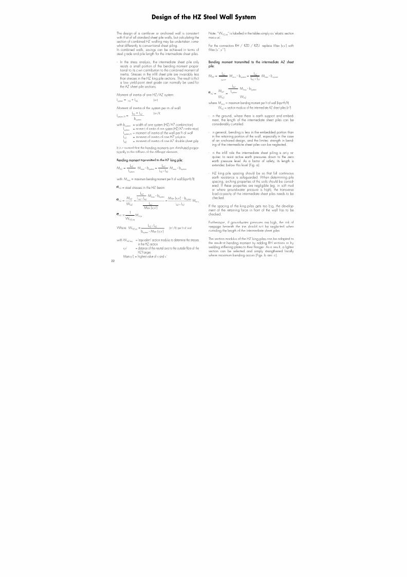
Depending on the structural combina-tion and grade of steel adopted, bend-ing moments up to 2020 kips • ft/ftcan be safel y resisted b y HZ walling.
Meaning the practical range of sec-tional combinations is characterised
b y loadings unsuitable for conventional sheet piling.Concurrentl y, an excellent section modulus to weight ratio
ensures economical design.
Theoutstandingfeature of thene w combinationis the e xtensi v e range of possible combina-tions using the entire AZ sheet pile offer, ifnecessary , including all up and do w n rolled
v ariants.
The HZ wall is a combined systemincorporating:
- HZ king piles as structural supports,
- AZ
sheet piles a
s intermedia
te infillelements.
A full range of standard seriessections interlinked b y specialconnectors.
S ystemwise assembl y of these basicelements yields a multitude of possiblecombinations.
All combinations are based on the same principle: struc-tural supports comprising one or more HZ king pile sec-
tions alternating with intermediate double AZ sheet pilesections.
Structurall y, the HZ king piles fulfil two different functions:
- as retaining members, the y resist horizontal loads resultingfrom earth and h ydrostatic pressures,
HZ Steel Wall S ystem
7/21/2019 Steel Sheet Piling
http://slidepdf.com/reader/full/steel-sheet-piling-56df2cc8ddaa3 4/32
7/21/2019 Steel Sheet Piling
http://slidepdf.com/reader/full/steel-sheet-piling-56df2cc8ddaa3 5/32
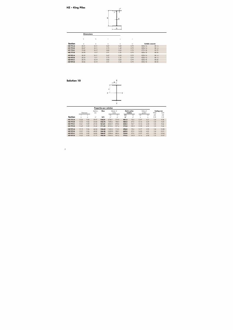
Sectional Mass Moment of *Elastic section **Elastic section Radius of Coating area
Dimensions area inertia modulus modulus g yration Water- Land-
v v’ v’’ v’’’ u u’ y- y z-z y- y z-z y - y y- y z-z side side
Section in in in in in in in2 lb/ft in4 in4 in3 in3 in3 in in f t2/f t f t2/f t
3
Properties per solution
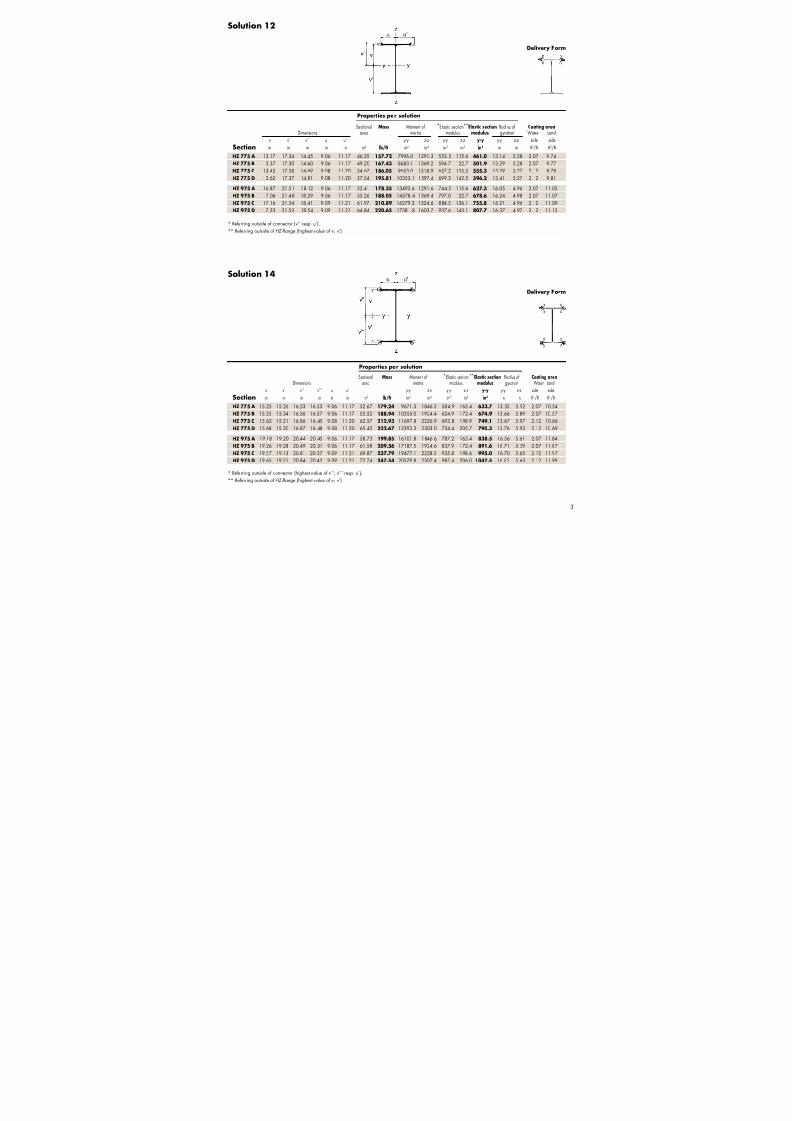
Solution 12
Solution 14
Properties per solution
Deli v ery Form
* Referring outside of connector (v’’ resp. u’),
** Referring outside of HZ -flange (highest value of v; v’)
* Referring outside of connector (highest value of v’’; v’’’ resp. u’),
** Referring outside of HZ -flange (highest value of v; v’)
HZ 775 A 13.17 17.34 14.45 9.06 11.17 46.35 157.72 7996.0 1291.3 553.5 115.6 461.0 13.14 5.28 2.07 9.74
HZ 775 B 13.37 17.30 14.60 9.06 11.17 49.20 167.43 8683.1 1369.2 594.7 122.7 501.9 13.29 5.28 2.07 9.77
HZ 775 C 13.45 17.38 14.69 9.08 11.20 54.67 186.05 9653.0 1518.9 657.2 135.5 555.3 13.29 5.27 2.12 9.79
HZ 775 D 13.62 17.37 14.81 9.08 11.20 57.54 195.81 10353.1 1597.4 699.3 142.5 596.2 13.41 5.27 2.12 9.81
HZ 975 A 16.87 21.51 18.12 9.06 11.17 52.41 178.35 13493.6 1291.6 744.5 115.6 627.3 16.05 4.96 2.07 11.05
HZ 975 B 17.06 21.48 18.29 9.06 11.17 55.26 188.05 14578.4 1369.4 797.0 122.7 678.6 16.24 4.98 2.07 11.07
HZ 975 C 17.16 21.54 18.41 9.09 11.21 61.97 210.89 16279.3 1524.6 884.5 136.1 755.8 16.21 4.96 2.12 11.09HZ 975 D 17.33 21.53 18.54 9.09 11.21 64.84 220.65 17381.8 1603.7 937.6 143.1 807.7 16.37 4.97 2.12 11.12
HZ 775 A 15.25 15.26 16.53 16.53 9.06 11.17 52.67 179.24 9671.3 1846.3 584.9 165.4 633.7 13.55 5.92 2.07 10.54HZ 775 B 15.33 15.34 16.56 16.57 9.06 11.17 55.52 188.94 10355.0 1924.4 624.9 172.4 674.9 13.66 5.89 2.07 10.57
HZ 775 C 15.62 15.21 16.86 16.45 9.08 11.20 62.57 212.93 11697.8 2226.9 693.8 198.9 749.1 13.67 5.97 2.12 10.66
HZ 775 D 15.68 15.30 16.87 16.48 9.08 11.20 65.43 222.67 12393.3 2303.0 734.4 205.7 790.3 13.76 5.93 2.12 10.69
HZ 975 A 19.18 19.20 20.44 20.45 9.06 11.17 58.73 199.85 16101.8 1846.6 787.2 165.4 838.5 16.56 5.61 2.07 11.84
HZ 975 B 19.26 19.28 20.49 20.51 9.06 11.17 61.58 209.56 17187.5 1924.6 837.9 172.4 891.6 16.71 5.59 2.07 11.87
HZ 975 C 19.57 19.13 20.81 20.37 9.09 11.21 69.87 237.79 19477.1 2228.3 935.8 198.6 995.0 16.70 5.65 2.12 11.97
HZ 975 D 19.65 19.21 20.84 20.42 9.09 11.21 72.74 247.54 20579.8 2307.4 987.4 206.0 1047.5 16.82 5.63 2.12 11.99
Sectional Mass Moment of *Elastic section**Elastic section Radius of Coating area
Dimensions area inertia modulus modulus g yration Water- Land-
v v’ v’’ u u’ y- y z-z y- y z-z y - y y- y z-z side side
Section in in in in in in2 lb/ft in4 in4 in3 in3 in3 in in f t2/f t f t2/f t
Deli v ery Form
7/21/2019 Steel Sheet Piling
http://slidepdf.com/reader/full/steel-sheet-piling-56df2cc8ddaa3 6/32
7/21/2019 Steel Sheet Piling
http://slidepdf.com/reader/full/steel-sheet-piling-56df2cc8ddaa3 7/32
Sectional Mass Moment of *Elastic section **Elastic section Radius of Coating area
Dimensions area inertia modulus modulus g yration Water- Land-
v v’ v’’ v’’’ u u’ y- y z-z y- y z-z y - y y- y z-z side side
Section in in in in in in in2 lb/ft in4 in4 in3 in3 in3 in in f t2/f t f t2/f t
5
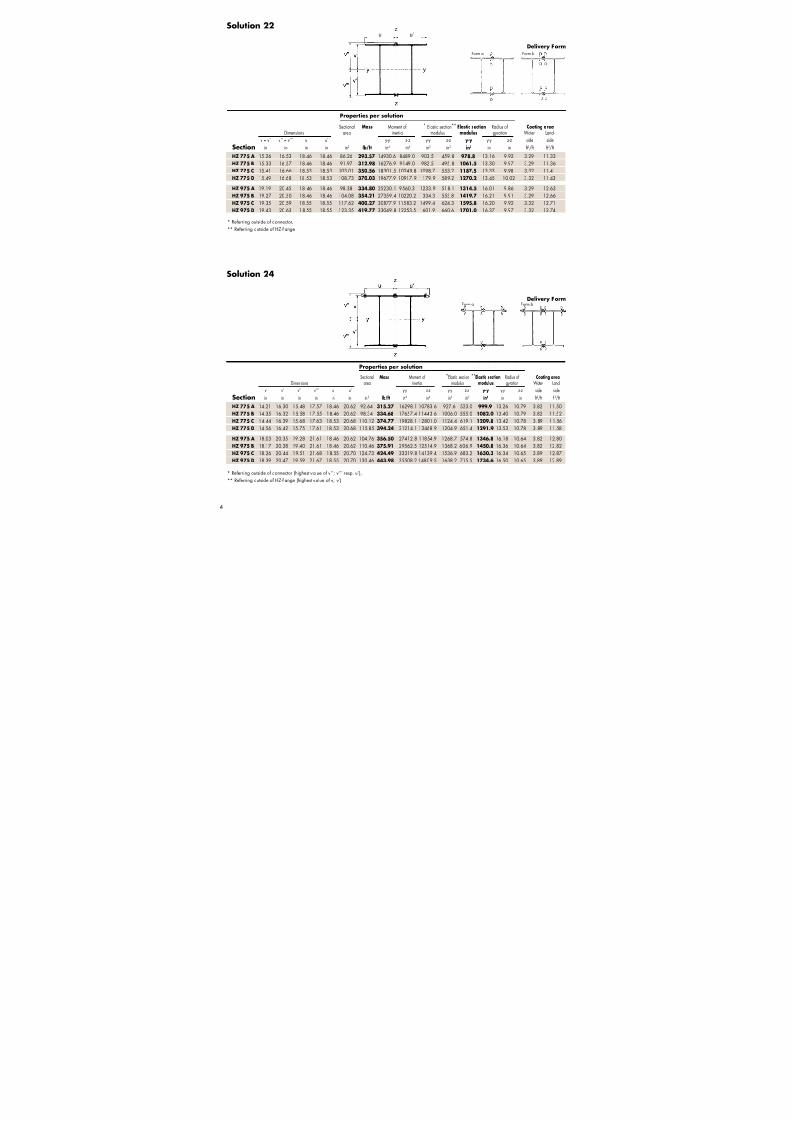
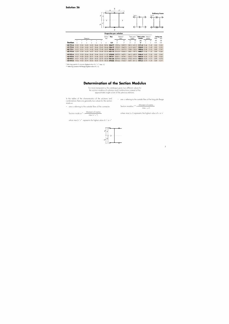
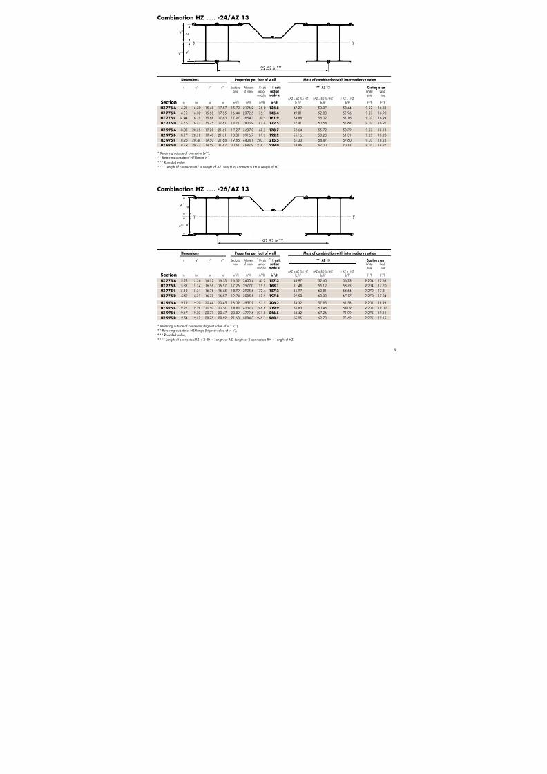
Solution 26
* Referring outside of connector (highest value of v’’; v’’’ resp. u’),
** Referring outside of HZ -flange (highest value of v; v’)
Determination of the Section Modulus
In the tables of the characteristics of the solutions andcombinations there are generall y two values for the sectionmodulus:
– one is referring to the outside fibre of the connector
Moment of inertiaSection modulus * =
max (v'',v''')
where max (v'',v''') represents the highest value of v'' or v'''
– one is referring to the outside fibre of the king pile flange
Moment of inertiaSection modulus ** =
max (v,v')
where max (v,v') represents the highest value of v or v'
For more transparenc y this ca talogue gives two different values forthe section modulus of solutions and combinations instead of the
approximate single value of the previous edi tions.
Form a Form b
Deli v ery Form
HZ 775 A 15.25 15.26 16.52 16.53 18.46 20.62 98.96 336.77 17872.4 13007.9 1081.3 631.0 1171.4 13.44 11.47 3.82 12.30
HZ 775 B 15.33 15.34 16.56 16.57 18.46 20.62 104.66 356.19 19233.9 13667.8 1161.0 662.7 1254.0 13.56 11.43 3.82 12.32
HZ 775 C 15.52 15.31 16.76 16.55 18.53 20.68 118.02 401.65 21767.6 15622.0 1298.6 755.5 1402.6 13.58 11.51 3.89 12.43
HZ 775 D 15.59 15.39 16.78 16.57 18.53 20.68 123.74 421.12 23153.9 16285.3 1380.1 787.5 1484.7 13.68 11.47 3.89 12.46
HZ 975 A 19.19 19.20 20.44 20.45 18.46 20.62 111.07 378.00 29879.9 14079.1 1461.2 682.9 1556.4 16.40 11.26 3.82 13.60
HZ 975 B 19.27 19.28 20.50 20.51 18.46 20.62 116.78 397.41 32037.1 14739.1 1562.2 714.9 1662.0 16.56 11.23 3.82 13.62
HZ 975 C 19.47 19.23 20.71 20.47 18.55 20.70 132.63 451.36 36370.0 16954.4 1756.6 819.2 1868.2 16.56 11.31 3.89 13.74HZ 975 D 19.54 19.32 20.75 20.52 18.55 20.70 138.36 470.86 38564.4 17624.7 1859.1 851.6 1973.5 16.70 11.29 3.89 13.77
Properties per solution

7/21/2019 Steel Sheet Piling
http://slidepdf.com/reader/full/steel-sheet-piling-56df2cc8ddaa3 8/32
h b t s Sectional Mass Moment of Elastic section Radius of Coating area
area inertia modulus g yration
y- y y - y y- y
Section in in in in in2 lb/ft in4 in3 in f t2/f t
6
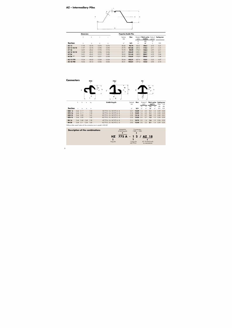
AZ – Intermediary Piles
Connectors
Description of the combinations
HZ 775 A - 1 2 / AZ 18
designationof the king pile
AZ 18 double pileas intermediate
king pile 1 king pileHZ 775 A
2 connectors1 RZD + 1 RZU
Without o ther specification a ll the connectors are in grade S 430 GP.
Dimensions Properties Double Piles
AZ 13 11.93 52.76 0.374 0.374 28.43 96.76 634.3 106.2 4.72 5.41
AZ 13 10/10 11.97 52.76 0.394 0.394 29.70 101.06 659.2 110.5 4.71 5.41
AZ 18 14.96 49.61 0.374 0.374 29.39 99.99 1035.0 138.5 5.93 5.61
AZ 18 10/10 15.00 49.61 0.394 0.394 30.71 104.49 1076.1 143.7 5.92 5.61
AZ 26 16.81 49.61 0.512 0.480 38.63 131.44 1680.3 200.2 6.59 5.84
AZ 26 +0.5 16.85 49.61 0.531 0.500 39.93 135.87 1732.9 206.0 6.59 5.84
AZ 13-770 13.54 60.63 0.354 0.354 30.04 102.21 827.4 122.0 5.25 6.07 AZ 18-700 16.54 55.12 0.354 0.354 30.21 102.81 1271.4 153.8 6.50 6.10
RZD 16 2.44 3.17 - 1.24 HZ 775 A - B / HZ 975 A - B 3.21 10.89 1.4 2.3 1.1 1.3 0.39 0.20
RZU 16 2.44 3.17 - 1.50 HZ 775 A - B / HZ 975 A - B 3.18 10.82 1.6 2.3 1.1 1.3 0.30 0.33
RZD 18 2.64 3.35 - 1.41 HZ 775 C - D / HZ 975 C - D 3.58 12.16 1.9 2.7 1.3 1.5 0.43 0.23
RZU 18 2.64 3.35 - 1.65 HZ 775 C - D / HZ 975 C - D 3.53 12.03 2.2 2.7 1.3 1.5 0.30 0.33
RH 16 2.44 2.68 0.48 1.28 HZ 775 A - B / HZ 975 A - B 3.16 10.75 2.0 1.4 1.6 1.0 0.36 0.30
RH 20 2.64 3.11 0.56 1.43 HZ 775 C - D / HZ 975 C - D 3.95 13.44 3.0 2.2 2.1 1.4 0.39 0.33
h b a a y Suitable king pile Sectional Mass Moment of Elastic section Coating area
area inertia modulus Water- Land-
y- y z-z y - y z-z side side
Section in in in in in2 lb/ft in4 in4 in3 in3 f t2/f t f t2/f t
7/21/2019 Steel Sheet Piling
http://slidepdf.com/reader/full/steel-sheet-piling-56df2cc8ddaa3 9/327
7/21/2019 Steel Sheet Piling
http://slidepdf.com/reader/full/steel-sheet-piling-56df2cc8ddaa3 10/32

7/21/2019 Steel Sheet Piling
http://slidepdf.com/reader/full/steel-sheet-piling-56df2cc8ddaa3 11/32

7/21/2019 Steel Sheet Piling
http://slidepdf.com/reader/full/steel-sheet-piling-56df2cc8ddaa3 12/3210
2070 mm ***
vv’’
v’v’’’
y y
2070 mm ***
v
y y
v’’
v’
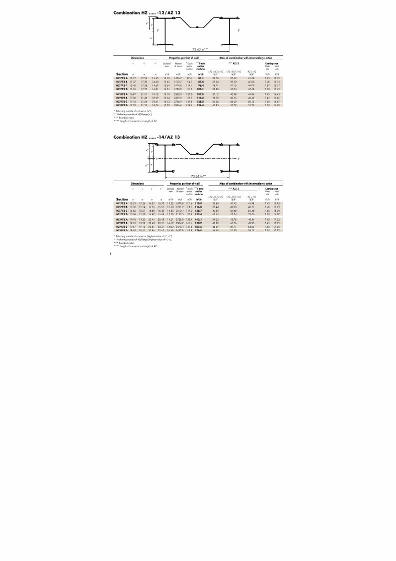
* Referring outside of connector (v’’),
** Referring outside of HZ -flange (v’),
*** Rounded value,
**** Length of connectors = Length of AZ
* Referring outside of connector (highest value of v’’; v’’’),
** Referring outside of HZ -flange (highest value of v; v’),
*** Rounded value,
**** Length of connectors = Length of AZ
Combination HZ ..... -12/ AZ 13-770
Combination HZ ..... -14/ AZ 13-770
HZ 775 A 13.17 17.34 14.45 11.25 1299.2 89.9 75.0 30.98 34.63 38.28 8.10 15.77
HZ 775 B 13.37 17.30 14.60 11.67 1400.5 95.9 80.9 32.41 36.06 39.71 8.10 15.80
HZ 775 C 13.45 17.38 14.69 12.47 1543.2 105.1 88.8 35.00 38.72 42.45 8.14 15.81
HZ 775 D 13.62 17.37 14.81 12.89 1646.4 111.2 94.8 36.43 40.16 43.88 8.14 15.84
HZ 975 A 16.87 21.51 18.12 12.14 2108.8 116.3 98.0 34.02 37.67 41.32 8.10 17.07
HZ 975 B 17.06 21.48 18.29 12.56 2268.5 124.0 105.6 35.45 39.09 42.74 8.10 17.10
HZ 975 C 17.16 21.54 18.41 13.55 2519.0 136.9 116.9 38.66 42.38 46.11 8.15 17.12HZ 975 D 17.33 21.52 18.54 13.97 2681.3 144.6 124.5 40.10 43.82 47.54 8.15 17.14
Dimensions Properties per foot of w all Mass of combination w ith in termediary section
v v’ v’’ v’’’ Sectional Moment * Elastic ** Elastic **** AZ 13-770 Coating area
area of inertia section section Water- Land-modulus modulus side side
l AZ = 60 % l HZ l AZ = 80 % l HZ l AZ = l HZ
Section in in in in in2/f t in4/f t in3/f t in3/ft lb/f t2 lb/f t2 lb/f t2 f t2/f t f t2/f t
HZ 775 A 15.25 15.26 16.53 16.53 12.18 1546.0 93.5 101.3 32.88 37.16 41.45 8.10 16.57HZ 775 B 15.33 15.34 16.56 16.57 12.60 1646.6 99.3 107.3 34.31 38.59 42.87 8.10 16.59
HZ 775 C 15.62 15.21 16.86 16.45 13.64 1844.4 109.4 118.1 37.38 41.89 46.41 8.14 16.69
HZ 775 D 15.68 15.30 16.87 16.48 14.06 1946.7 115.4 124.2 38.81 43.32 47.84 8.14 16.72
HZ 975 A 19.18 19.20 20.44 20.45 13.07 2492.8 121.8 129.8 35.92 40.20 44.48 8.10 17.87
HZ 975 B 19.26 19.28 20.49 20.51 13.49 2652.7 129.4 137.5 37.34 41.63 45.91 8.10 17.90
HZ 975 C 19.57 19.13 20.81 20.37 14.71 2989.8 143.7 152.7 41.04 45.55 50.07 8.15 17.99
HZ 975 D 19.65 19.21 20.84 20.42 15.13 3152.2 151.2 160.4 42.47 46.99 51.50 8.15 18.02
Dimensions Properties per foot of w all Mass of combination w ith in termediary section
v v’ v’’ Sectional Moment * Elastic ** Elastic **** AZ 13-770 Coating area
area of inertia section section Water- Land-modulus modulus side side
l AZ = 60 % l HZ l AZ = 80 % l HZ l AZ = l HZ
Section in in in in2/f t in4/f t in3/f t in3/ft lb/f t2 lb/f t2 lb/f t2 f t2/f t f t2/f t
81.50 in***
81.50 in***

7/21/2019 Steel Sheet Piling
http://slidepdf.com/reader/full/steel-sheet-piling-56df2cc8ddaa3 13/32

7/21/2019 Steel Sheet Piling
http://slidepdf.com/reader/full/steel-sheet-piling-56df2cc8ddaa3 14/32
1790 mm ***
vv’’
v’v’’’
y y
1790 mm ***
vv’’
v’
y y
12
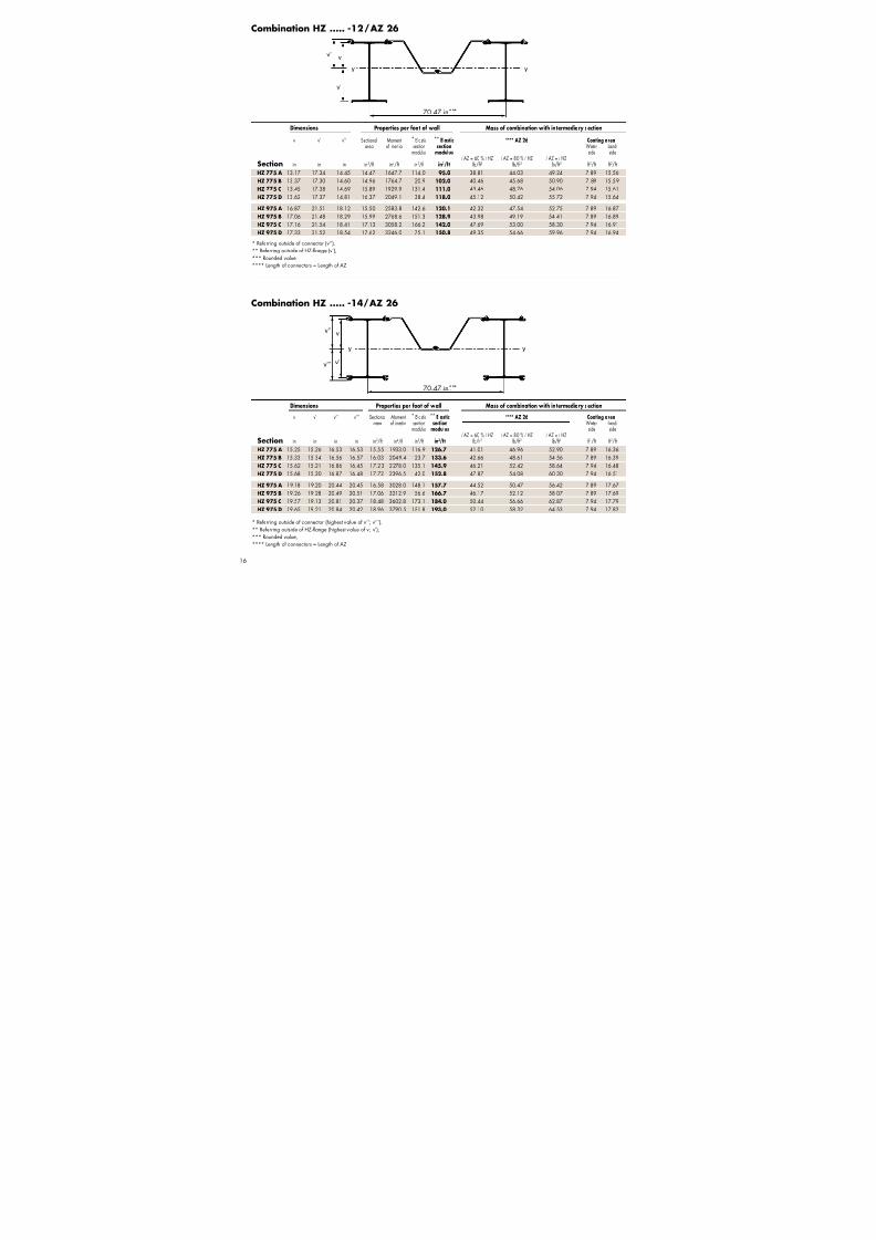
Combination HZ ..... -12/ AZ 18
Combination HZ ..... -14/ AZ 18
* Referring outside of connector (v’’),
** Referring outside of HZ -flange (v’),
*** Rounded value,
**** Length of connectors = Length of AZ
* Referring outside of connector (highest value of v’’; v’’’),
** Referring outside of HZ -flange (highest value of v; v’),
*** Rounded value,
**** Length of connectors = Length of AZ
Dimensions Properties per foot of w all Mass of combination w ith in termediary section
v v’ v’’ v’’’ Sectional Moment * Elastic ** Elastic **** AZ 18 Coating area
area of inertia section section Water- Land-modulus modulus side side
l AZ = 60 % l HZ l AZ = 80 % l HZ l AZ = l HZ
Section in in in in in2/f t in4/f t in3/f t in3/ft lb/f t2 lb/f t2 lb/f t2 f t2/f t f t2/f t
Dimensions Properties per foot of w all Mass of combination w ith in termediary section
v v’ v’’ Sectional Moment * Elastic ** Elastic **** AZ 18 Coating area
area of inertia section section Water- Land-modulus modulus side side
l AZ = 60 % l HZ l AZ = 80 % l HZ l AZ = l HZ
Section in in in in2/f t in4/f t in3/f t in3/ft lb/f t2 lb/f t2 lb/f t2 f t2/f t f t2/f t
HZ 775 A 13.17 17.34 14.45 12.90 1537.8 106.4 88.6 35.60 39.74 43.89 7.65 15.32
HZ 775 B 13.37 17.30 14.60 13.38 1654.9 113.4 95.6 37.25 41.40 45.54 7.65 15.35
HZ 775 C 13.45 17.38 14.69 14.31 1820.0 123.9 104.7 40.25 44.48 48.71 7.70 15.37
HZ 775 D 13.62 17.37 14.81 14.80 1939.2 130.9 111.7 41.91 46.14 50.37 7.70 15.39
HZ 975 A 16.87 21.51 18.12 13.93 2474.0 136.5 114.9 39.11 43.26 47.40 7.65 16.63
HZ 975 B 17.06 21.48 18.29 14.41 2658.7 145.4 123.8 40.76 44.91 49.05 7.65 16.65
HZ 975 C 17.16 21.54 18.41 15.56 2948.3 160.1 136.9 44.48 48.71 52.94 7.70 16.67HZ 975 D 17.33 21.52 18.54 16.04 3136.1 169.2 145.7 46.14 50.37 54.60 7.70 16.70
HZ 775 A 15.25 15.26 16.53 16.53 13.97 1823.1 110.3 119.4 37.80 42.67 47.55 7.65 16.12HZ 775 B 15.33 15.34 16.56 16.57 14.46 1939.5 117.0 126.4 39.45 44.33 49.20 7.65 16.15
HZ 775 C 15.62 15.21 16.86 16.45 15.66 2168.2 128.6 138.8 43.00 48.14 53.29 7.70 16.24
HZ 775 D 15.68 15.30 16.87 16.48 16.15 2286.6 135.5 145.8 44.65 49.80 54.95 7.70 16.27
HZ 975 A 19.18 19.20 20.44 20.45 15.00 2918.1 142.7 152.0 41.31 46.18 51.06 7.65 17.42
HZ 975 B 19.26 19.28 20.49 20.51 15.49 3103.0 151.3 160.9 42.96 47.84 52.72 7.65 17.45
HZ 975 C 19.57 19.13 20.81 20.37 16.90 3492.9 167.9 178.5 47.23 52.37 57.52 7.70 17.55
HZ 975 D 19.65 19.21 20.84 20.42 17.39 3680.6 176.6 187.3 48.89 54.03 59.18 7.70 17.57
70.47 in***
70.47 in***

7/21/2019 Steel Sheet Piling
http://slidepdf.com/reader/full/steel-sheet-piling-56df2cc8ddaa3 15/32
7/21/2019 Steel Sheet Piling
http://slidepdf.com/reader/full/steel-sheet-piling-56df2cc8ddaa3 16/3214
1930 mm ***
vv’’
v’v’’’
y y
1930 mm ***
vv’’
v’
y y
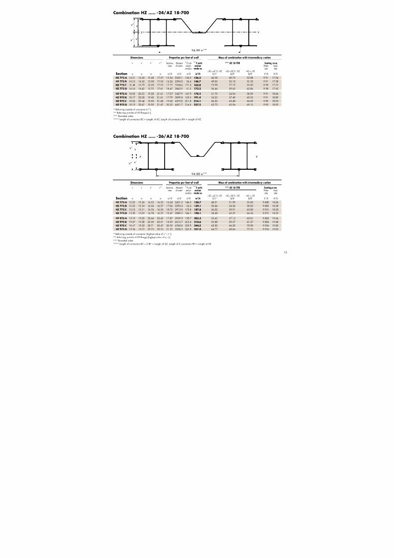
Combination HZ ..... -12/ AZ 18-700
Combination HZ ..... -14/ AZ 18-700
* Referring outside of connector (v’’),
** Referring outside of HZ -flange (v’),
*** Rounded value,
**** Length of connectors = Length of AZ
* Referring outside of connector (highest value of v’’; v’’’),
** Referring outside of HZ -flange (highest value of v; v’),
*** Rounded value,
**** Length of connectors = Length of AZ
Dimensions Properties per foot of w all Mass of combination w ith in termediary section
v v’ v’’ v’’’ Sectional Moment * Elastic ** Elastic **** AZ 18-700 Coating area
area of inertia section section Water- Land-modulus modulus side side
l AZ = 60 % l HZ l AZ = 80 % l HZ l AZ = l HZ
Section in in in in in2/f t in4/f t in3/f t in3/ft lb/f t2 lb/f t2 lb/f t2 f t2/f t f t2/f t
Dimensions Properties per foot of w all Mass of combination w ith in termediary section
v v’ v’’ Sectional Moment * Elastic ** Elastic **** AZ 18-700 Coating area
area of inertia section section Water- Land-modulus modulus side side
l AZ = 60 % l HZ l AZ = 80 % l HZ l AZ = l HZ
Section in in in in2/f t in4/f t in3/f t in3/ft lb/f t2 lb/f t2 lb/f t2 f t2/f t f t2/f t
HZ 775 A 13.17 17.34 14.45 12.09 1463.6 101.3 84.4 33.28 37.21 41.15 8.13 15.81
HZ 775 B 13.37 17.30 14.60 12.54 1572.1 107.7 90.9 34.81 38.75 42.68 8.13 15.83
HZ 775 C 13.45 17.38 14.69 13.40 1725.3 117.5 99.2 37.59 41.61 45.62 8.18 15.85
HZ 775 D 13.62 17.37 14.81 13.86 1835.9 124.0 105.7 39.13 43.14 47.16 8.18 15.88
HZ 975 A 16.87 21.51 18.12 13.05 2331.9 128.6 108.3 36.54 40.47 44.40 8.13 17.11
HZ 975 B 17.06 21.48 18.29 13.50 2503.1 136.8 116.5 38.07 42.00 45.94 8.13 17.13
HZ 975 C 17.16 21.54 18.41 14.56 2771.8 150.6 128.7 41.52 45.53 49.54 8.18 17.15HZ 975 D 17.33 21.52 18.54 15.01 2945.9 158.9 136.9 43.06 47.07 51.08 8.18 17.18
HZ 775 A 15.25 15.26 16.53 16.53 13.09 1728.2 104.5 113.3 35.32 39.93 44.54 8.13 16.60HZ 775 B 15.33 15.34 16.56 16.57 13.54 1836.2 110.8 119.7 36.85 41.46 46.08 8.13 16.63
HZ 775 C 15.62 15.21 16.86 16.45 14.65 2048.2 121.5 131.1 40.14 45.00 49.86 8.18 16.72
HZ 775 D 15.68 15.30 16.87 16.48 15.10 2158.1 127.9 137.5 41.68 46.54 51.40 8.18 16.75
HZ 975 A 19.18 19.20 20.44 20.45 14.05 2743.8 134.1 142.8 38.58 43.19 47.80 8.13 17.91
HZ 975 B 19.26 19.28 20.49 20.51 14.50 2915.2 142.1 151.2 40.11 44.72 49.33 8.13 17.93
HZ 975 C 19.57 19.13 20.81 20.37 15.81 3276.8 157.4 167.4 44.07 48.93 53.79 8.18 18.03
HZ 975 D 19.65 19.21 20.84 20.42 16.26 3451.0 165.5 175.7 45.61 50.47 55.33 8.18 18.06
75.98 in***
75.98 in***
7/21/2019 Steel Sheet Piling
http://slidepdf.com/reader/full/steel-sheet-piling-56df2cc8ddaa3 17/32
7/21/2019 Steel Sheet Piling
http://slidepdf.com/reader/full/steel-sheet-piling-56df2cc8ddaa3 18/32

7/21/2019 Steel Sheet Piling
http://slidepdf.com/reader/full/steel-sheet-piling-56df2cc8ddaa3 19/32

7/21/2019 Steel Sheet Piling
http://slidepdf.com/reader/full/steel-sheet-piling-56df2cc8ddaa3 20/3218
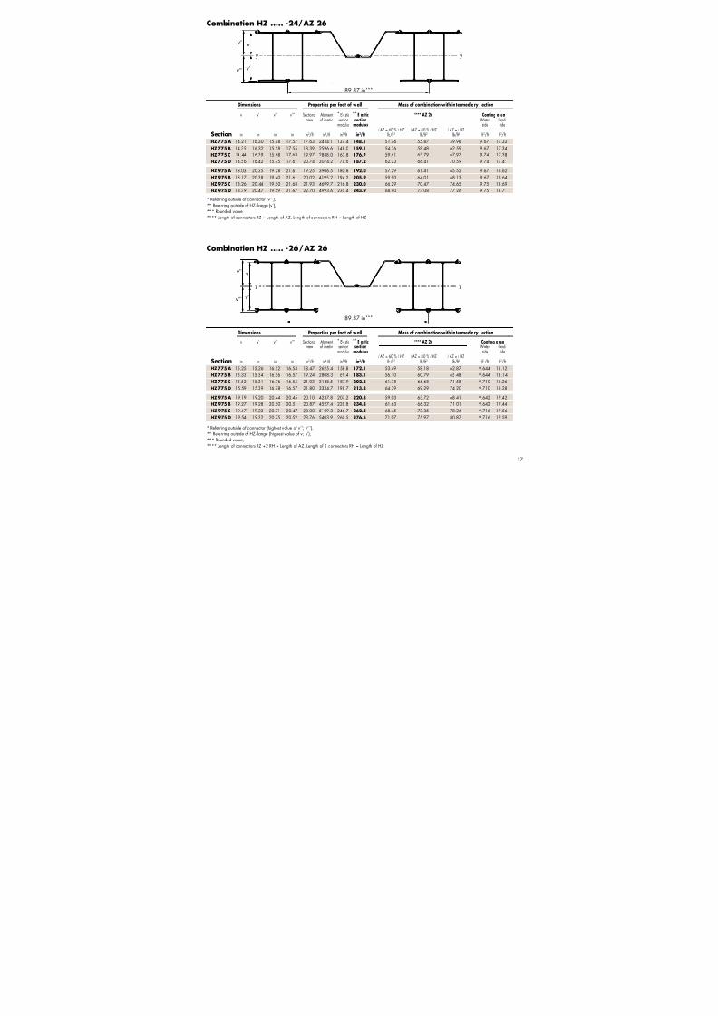
Combination C 1
* Referring outside of connector (v’’),
** Referring outside of HZ -flange (v’)
Driving Direction
Combination C 23
* Referring outside of connector (v’’’),
** Referring outside of HZ -flange (v’)
Deli v ery Form
Dimensions Properties per foot of w all
b v v’ v’’ Sectional Mass Moment * Elastic ** Elastic Coating area
area of inertia section section Water- Land-
modulus modulus side sideSection in in in in in2/f t lb/ft2 in4/f t in3/f t in3/ft f t2/f t f t2/f t
HZ 775 A 18.70 14.14 16.37 15.41 27.68 94.19 4755.9 308.7 290.4 1.75 9.52
HZ 775 B 18.70 14.28 16.39 15.52 29.51 100.41 5190.0 334.5 316.8 1.75 9.54
HZ 775 C 18.86 14.25 16.58 15.49 32.77 111.54 5778.3 373.0 348.5 1.77 9.57
HZ 775 D 18.86 14.38 16.60 15.57 34.59 117.73 6218.4 399.3 374.6 1.77 9.59
HZ 975 A 18.70 17.96 20.42 19.21 31.56 107.42 8047.3 418.8 394.0 1.75 10.82
HZ 975 B 18.70 18.10 20.44 19.34 33.39 113.65 8732.8 451.6 427.2 1.75 10.85
HZ 975 C 18.90 18.06 20.64 19.31 37.34 127.09 9742.2 504.6 472.1 1.77 10.87HZ 975 D 18.90 18.20 20.66 19.40 39.16 133.28 10434.4 537.8 505.1 1.77 10.90
Dimensions Properties per foot of w all
b v v’ v’’ v’’’ Sectional Mass Moment * Elastic ** Elastic Coating area
area of inertia section section Water- Land-
modulus modulus side sideSection in in in in in in2/f t lb/ft2 in4/f t in3/f t in3/ft f t2/f t f t2/f t
HZ 775 A 37.40 14.72 15.79 15.99 17.07 28.69 97.64 5018.6 294.1 317.7 3.50 11.27HZ 775 B 37.40 14.83 15.84 16.06 17.07 30.52 103.86 5452.3 319.4 344.1 3.50 11.30
HZ 775 C 37.72 14.85 15.98 16.09 17.22 34.03 115.81 6104.2 354.5 382.1 3.54 11.34
HZ 775 D 37.72 14.96 16.03 16.14 17.21 35.85 122.01 6543.5 380.2 408.3 3.54 11.37
HZ 975 A 37.40 18.60 19.79 19.85 21.04 32.58 110.87 8456.6 401.9 427.3 3.50 12.57
HZ 975 B 37.40 18.71 19.84 19.94 21.07 34.41 117.10 9142.5 433.9 460.8 3.50 12.60
HZ 975 C 37.80 18.73 19.97 19.97 21.21 38.60 131.35 10250.1 483.1 513.2 3.55 12.65
HZ 975 D 37.80 18.83 20.02 20.04 21.23 40.42 137.54 10942.2 515.5 546.5 3.55 12.67
Form a Form b
Driving Direction
Deli v ery Form
7/21/2019 Steel Sheet Piling
http://slidepdf.com/reader/full/steel-sheet-piling-56df2cc8ddaa3 21/32
7/21/2019 Steel Sheet Piling
http://slidepdf.com/reader/full/steel-sheet-piling-56df2cc8ddaa3 22/3220
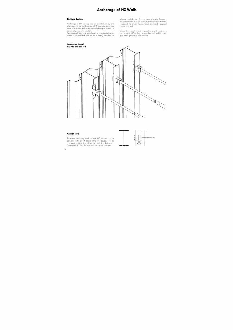
Anchorage of HZ Walls
Tie-Back S ystem
Anchorage of HZ walling can be provided simpl y andeffec-tivel y. A tie rod link s each HZ king pile to a steelsheet pile anchor wall or to isolated sheet pile panels - aparticularl y economic solution.Because each king pile is anchored, a complicated walersystem is not required. The tie rod is simpl y linked to the
relevant H-pile b y two T-connectors and a pin. T-connec-tors are threaded through oxyacetylene-cut slots in the rearflanges of the driven H-piles. Loads are thereb y appliedclose to the web.
Conventional anchoring, incorporating a waler system, isalso possible. HZ walling can also be anchored b y batterpiles or b y ground or rock anchors.
Anchor slots
Connection DetailHZ Pile and Tie rod
Anchor Slots
To reduce anchoring work on site, HZ sections can bedelivered with precut anchor slots, on request. The ac-compan ying illustration shows tie rod slots being cut.Dimensions “h” and “b” vary with the tie rod diameter.
7/21/2019 Steel Sheet Piling
http://slidepdf.com/reader/full/steel-sheet-piling-56df2cc8ddaa3 23/322

7/21/2019 Steel Sheet Piling
http://slidepdf.com/reader/full/steel-sheet-piling-56df2cc8ddaa3 24/32

7/21/2019 Steel Sheet Piling
http://slidepdf.com/reader/full/steel-sheet-piling-56df2cc8ddaa3 25/322
Fig. a Fig. b Fig. c
The new combined walling, in which the full range ofAZ sections can be used as intermediate sheet piles, offersflexibility in terms of design. Heavier AZ sections can also beselected to enhance corrosion resistance or in cases involv-ing difficult driving conditions.
The HZ king piles are capable of transferring high verticalloads to the subsoil. In such cases, stress anal ysis shouldinclude vertical loads and additional bending momentsinduced b y deflection.

7/21/2019 Steel Sheet Piling
http://slidepdf.com/reader/full/steel-sheet-piling-56df2cc8ddaa3 26/3224
Procedure
HZ walls can be installed on land and in water. In bothcases the procedure is the same. First the king piles aredriven in small or large driving steps. Then the intermedi-
ate sheet piles are pitched and driven. If geotechnicalconditions are difficult, it ma y be necessary to carry outthe whole driving operation in two stages. In this case thefirst stage is to drive the king piles as far as possible, orto a predetermined intermediate depth. The intermediatesheet piles are then threaded and driven, generall y to thesame depth as the king piles, or to a shallower depth. Thesecond stage is to drive first the king piles and then the infillsheets down to the design depth or to refusal.
Dri v ing equipment and dri v ing aids
With current technolog y hammer or vibratory equipmentcan be used to drive king and intermediate sheet piles.
Vibratory equipment should be preferred wherever pos-sible (less damage to the pile). A combination of the twotechniques can be used above all in driving the king piles.In this case the king piles are first driven using vibration, asdescribed above, and then the final depth is reached usinga hammer. T ypes of hammers used are free-fall hammers,diesel hammers and h ydraulic hammers.
If using free-fall or diesel hammers, a driving cap must beused, and in the case of a h ydraulic hammer, a drivingplate which fits the pile head. If, however, vibration isused for driving, correct load transfer to the pile must beensured b y fitting a corresponding clamp to the pile head.Double clamps are used for box piles and for intermediate
AZ sheet piles.Intermediate sheet piles are generall y driven b y vibrationalmeans.
Installing combined HZ w alls
If geotechnical conditions are difficult, driving is facilitatedb y means of auxiliary techniques such as:
- Low-pressure or high-pressure jetting in granular or lightl ycohesive soil
- Predrilling- Drillings combined with soil replacement- Pre-blasting- Thickening the cross section at the toe of the pile in cohe-
sive soils with the aim of reducing skin friction.These techniques appl y to king piles as well as to inter-mediate sheet piles.
Installation methods
It is essential that the king piles are driving in the correctposition and verticall y, or a t the prescribed ba tter. Two dif-ferent methods can be used.
Method 1Use of a template with two guide levels at which the pitch-ing positions for the piles are set. The vertical distancebetween the two guide levels should not be less than 3 m.Wherever possible a greater distance should be chosen.The lower guide should be set as low as possible. Whendriving in water the template is mounted on auxiliary piles.On land the template can stand on the ground and shouldbe secured firml y against an y shifting. The template mustof course be correctl y a ligned with the wall axis.
Depending on the design, such templates can have space for5 to 9 king piles. These primary piles are driven using a free-
hanging vibrator or a hammer guided b y a hanging leader,the vibrator being the most commonl y used equipment.When all the piles of a template are driven, the templateis repositioned.
Intermediate sheet piles can then be installed, for example,b y a second driving team.

7/21/2019 Steel Sheet Piling
http://slidepdf.com/reader/full/steel-sheet-piling-56df2cc8ddaa3 27/322
Method 2
The king piles are driven using piling equipment guided b ya fixed leader. The correct driving angle, in the direction ofthe pile axis, must be ensured b y the leader, and the cor-rect positioning through a s imple horizontal driving guide.When piling in water the latter is secured above the waterlevel on auxiliary piles, in a ll other cases i t is set down onthe driving platform and secured.
In both methods it is important to constantl y check thatthe position of the king piles is as c lose as possible to thedesign position. This is essential for trouble-free driving ofthe intermediate sheet piles. A t the depth of the toe of thesheet piling, the spacing between the king piles should notdeviate b y more than 200 mm.
Useful hints
If the rock horizon is higher than the required penetrationdepth of the combined wall the bottom of the piling can besecured b y dowelling the king pile to the underl ying rock (toe pin). Another solution is to pitch the king piles into cor-responding predrillings.
It is advisable to choose a vibrator with a sufficient powerreserve. This helps guard against the danger of interlock damage through overheating.
Hammers should also be sufficientl y powerful so as to avoid,for example, local deformation of the piles. Hammers withvariable impact energ y are preferable.
If, when installing the intermediate sheet piles, progressis impossible or can onl y be achieved through excessivedriving energ y, check the following:
- Check that there are no obstructions in the soil. This canbe done, for example, b y extracting the intermediatesheet pile and re-driving it outside the interlock s.
- Check that the spacing and the positioning of the kingpiles is correct. This can be done, for example, b y meansof an inclinometer. A tube of the same diameter as theinclinometer is fitted with a corresponding interlock pieceand jetted in at the back of the king piles. The measure-ments taken b y the inclinometer will give informationon the actual position of the king pile at the relevantdepths.
If it is established that the spacing between the king pilesdoes not correspond to the requirements, the king pilesmust be extracted and redriven.
It is not recommended to force the driving of an interme-diate sheet pile, as experience shows that this generall yleads to damage and often to de-clutching problems.
If geotechnical conditions are problematic and if drivingis expected to be difficult, it ma y be advisable to fit jet-ting tubes to the intermediate sheet piles, close to the freethreading interlock s, for low-pressure jetting to facilitatedriving. For high-pressure jetting it is recommended touse an appropriatel y equipped displacement pile. Thisdisplacement pile is driven prior to inserting the actualintermediate sheet pile, and then extracted.
double clamps
Informative drawings
tubes forlow pressure jetting
thickening ofthe cross section

7/21/2019 Steel Sheet Piling
http://slidepdf.com/reader/full/steel-sheet-piling-56df2cc8ddaa3 28/32
7/21/2019 Steel Sheet Piling
http://slidepdf.com/reader/full/steel-sheet-piling-56df2cc8ddaa3 29/322
Deli v ery Conditions
A v ailable ma x imum length of piles
For greater delivery lengths than indicated, enquire in advance.
HZ 108 f t
AZ 102 f t
RZD/RZU 79 f t
RH 79 f t
Standard referred to : Comparable International StandardsEN 10248
Grade Min. Min. Min. USA Canada Japan yield tensile elongationpoint strength
Lo=5.65 So CSA JISksi ksi % ASTM G 4021 A 5528
Steel Grades
S 240 GP 34.8 49.3 26
S 270 GP 39.1 59.4 24 A 328 Gr. 260 W SY 295S 320 GP 46.4 63.8 23 Gr. 300 W
S 355 GP 51.5 69.6 22 A 572 Gr. 50; A 690 Gr. 350 W
S 390 GP 56.5 71.0 20 A 572 Gr. 55 SY 390
S 430 GP 62.3 73.9 19 A 572 Gr. 60 Gr. 400 W
Mill specification:
S 460 AP(*) 66.7 79.7 17 A 572 Gr.65
ASTM A690 a v ailable w ith f y k ≥ 50 k si
(*) For more details, please contact our technical department.
The mechanical properties are shown in thetable indicating comparable international stan-dards to which sheet piles can be ordered.
The standard we normall y refer to regardingsteel grades for hot-rolled sheet piles is EN10248 Part 1.
Suppl y to other standards is possibl e onrequest.
For the chemical anal ysis see correspondingstandard.
Other qualities of the type :
– steel with copper addition– special steels– steel with an improved corrosion resis-
tance, on request.
A proposed galvanisation of the finished productfor corrosion protection for instance, has aninfluence on the chemical anal ysis and must bespecified in the purchase order.
It is recommended that the manuf acturer beinformed b y the purchaser at the time of theorder, if a surf ace treatment on the product isforeseen af ter delivery.
Tolerances following EN 10248 HZ AZ
Weight ± 5 %
Length ± 8 in
Thickness e ≤ 0.492 in : + 0.08 in / - 0.04 in e ≤ 0.335 in : ± 0.02 in
e > 0.492 in : + 0.10 in / - 0.06 in e > 0.335 in : ± 6 %
Height < 20 in : ± 0.20 in ≤ 8 in : ± 0.20 in
≥ 20 in : ± 0.28 in 8 in < ± 0.24 in < 12 in
≥ 12 in : ± 0.28 in
Width single pile ± 2 %
Width interlocked elements ± 3 %
Straightness 0.2 % of the length
Ends out of square 2 % b
Tolerances following ASTM A6 HZ AZ
Weight ± 2.5 %
Length - 0 / + 5 in
7/21/2019 Steel Sheet Piling
http://slidepdf.com/reader/full/steel-sheet-piling-56df2cc8ddaa3 30/3228
Form a Form b
Form a Form b
Form a Form b
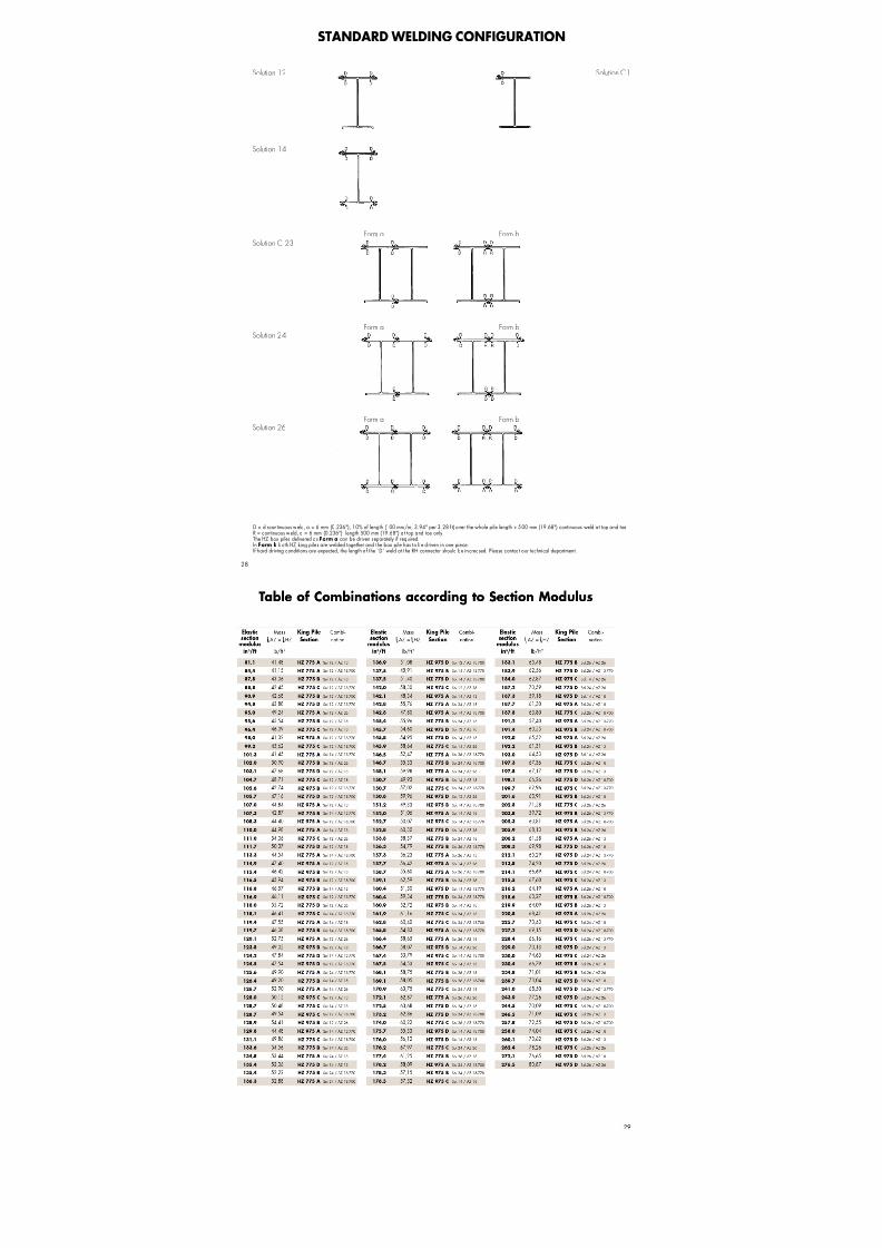
STANDARD WELDING CONFIGURATION
D = discontinuous w eld, a = 6 mm (0.236"), 10% of length (100 mm/m, 3.94" per 3 .28 f t) over the whole pile length + 5 00 mm (19.68") continuous weld a t top and toeR = continuous w eld, a = 6 mm (0.236"), length 500 mm (19.68") a t top and toe onl yThe HZ box piles delivered as Form a can be driven separatel y if required.In Form b both HZ king piles are welded together and the box pile has to be d riven in one piece.If hard driving conditions are expected, the length o f the “D” weld a t the RH connector should be increased. Please contact our technical department.
Solution 12
Solution 14
Solution C 23
Solution 24
Solution 26
Solution C1

7/21/2019 Steel Sheet Piling
http://slidepdf.com/reader/full/steel-sheet-piling-56df2cc8ddaa3 31/32

7/21/2019 Steel Sheet Piling
http://slidepdf.com/reader/full/steel-sheet-piling-56df2cc8ddaa3 32/32
Sheet Piling Arcelor Commercial RPS S.à r.l.
66, rue de LuxembourgL-4221 Esch-sur-Alzette (Luxembourg)
l
Skyline Steel, LLC
8, Woodhollow RoadParsippany, NJ 07054
l 4


