steel making
37
STEEL MAKING S.F. Stiemer steel_making.docx 12/10/2009 page 1 of 37 Steel / making / properties / fabrication / use compiled from various sources by S.F. Stiemer Vancouver, 2006
-
Upload
cat-menancio -
Category
Documents
-
view
99 -
download
0
description
steel making process
Transcript of steel making

STEEL MAKING S.F. Stiemer
steel_making.docx 12/10/2009 page 1 of 37
Steel / making / properties / fabrication / use
compiled from various sources by S.F. Stiemer
Vancouver, 2006

STEEL MAKING S.F. Stiemer
steel_making.docx 12/10/2009 page 2 of 37
Iron ....................................................................................................................... 4 Preparing the raw materials .................................................................................................................. 4
The blast furnace ................................................................................................................................... 5
Refining iron ......................................................................................................................................... 6
Materials ............................................................................................................................................... 6
The Basic Oxygen Converter ............................................................................. 7 The basic oxygen sequence ................................................................................................................... 8
The Electric Arc Furnace .................................................................................... 8 Electric Arc Stages ................................................................................................................................ 9
Special quality steels ............................................................................................................................. 9
Minimills ............................................................................................................................................. 10
Types of steel .................................................................................................... 10 Chemistry .......................................................................................................... 10
Reactivity of metals ............................................................................................................................ 10
Reduction and oxidation ..................................................................................................................... 10
Another redox reaction ....................................................................................................................... 11
Oxidising iron ..................................................................................................................................... 11
Reactions between acids and bases ..................................................................................................... 11
Endothermic and exothermic reactions ............................................................................................... 11
Properties of steels ........................................................................................... 12 Secondary Steelmaking ................................................................................... 14
Casting ................................................................................................................................................ 15
Continuous Casting ............................................................................................................................. 15
Oxygen control.................................................................................................................................... 16
Removal of impurities......................................................................................................................... 16
Inclusions for improved machinability ............................................................................................... 17
Ladle top slag ...................................................................................................................................... 18
Slag glaze ............................................................................................................................................ 18
Ladle stirring ....................................................................................................................................... 19
Vacuum treatment ............................................................................................................................... 19
Hot Rolling ......................................................................................................... 20 Plate mills............................................................................................................................................ 20
Strip mills ............................................................................................................................................ 20
Long product mills .............................................................................................................................. 21
Cooling ................................................................................................................................................ 21
Further processing ........................................................................................... 21 Cold Rolling & Drawing .................................................................................... 21 Coating ............................................................................................................... 22
Electrolytic Tinplate (ET) ................................................................................................................... 23

STEEL MAKING S.F. Stiemer
steel_making.docx 12/10/2009 page 3 of 37
Electrolytic Chromium/Chromium Oxide Coated Steel - ECCS (Hi-Top) ........................................ 23
Polymer Laminated Steel (Ferrolite) .................................................................................................. 23
Hot-Dip Lead/Tin Alloy Coated Steel ................................................................................................ 23
Pre-Painted Steel ................................................................................................................................. 23
Hot-Dip Zinc-Coated Steel ................................................................................................................. 24
Hot-Dip Iron-Zinc Alloy Coated Steel (Galvannealed Steel) ............................................................. 24
Hot-Dip Zinc/Aluminium Alloy Coated Steel .................................................................................... 24
Electro-Zinc Coated Steel ................................................................................................................... 24
Zinc-Nickel Alloy Electro-Coated Steel (Nizec) ................................................................................ 24
Inherent corrosion resistance .............................................................................................................. 24
Fabrication ......................................................................................................... 24 Weldability .......................................................................................................................................... 24
Fusion welding .................................................................................................................................... 25
Spot welding ....................................................................................................................................... 26
Friction welding .................................................................................................................................. 26
Some of the end-uses of steel ......................................................................... 26 Bridges ................................................................................................................................................ 26
Engineering ......................................................................................................................................... 26
Construction ....................................................................................................................................... 27
Ships .................................................................................................................................................... 27
In the home ......................................................................................................................................... 27
Cars ..................................................................................................................................................... 28
Strength of Steel ............................................................................................... 29 Fe-C phase diagram ............................................................................................................................ 30
Toughness ........................................................................................................................................... 31
Effect of grain size ............................................................................................................................ 31
Effect of microstructure .................................................................................................................... 32
Effect of solid solution strengthening ............................................................................................... 32
Effect of precipitates ......................................................................................................................... 32
Effect of dislocations ........................................................................................................................ 33
Transformation diagrams (CCT & TTT) .......................................................................................... 33
Heat treatment ..................................................................................................................................... 35
Surface hardening ............................................................................................................................... 35
Controlled alloying additions to steel ............................................................................................... 36
Carburising ........................................................................................................................................ 36
Nitriding ............................................................................................................................................ 36
Carbo-nitriding .................................................................................................................................. 36
Diagrammes ...................................................................................................... 37

STEEL MAKING S.F. Stiemer
steel_making.docx 12/10/2009 page 4 of 37
Iron Making iron is the first step in the production of steel. Iron is usually made from iron ore, coal and limestone - although some plants around the world have developed alternative methods of iron manufacture. These newer methods require slightly different raw materials but iron ore, coal and limestone remain the starting point for most steel manufacture.
Preparing the raw materials Very little coal is used directly in the Blast Furnace to make iron. Most of the coal is packed into sealed ovens and heated strongly until it decomposes. This produces coke, a much purer form of carbon than coal. Coke has three important jobs in the Blast Furnace:
it burns to give the very high temperatures required for Blast Furnace reactions;
it produces the carbon monoxide gas that reduces the ore to iron;
it is strong and supports the column of raw materials in the furnace. this allows reactive gases to pass through the furnace
Much of the ore that comes to the steelworks is in a finely ground state. In this condition, the ore is difficult to handle without creating dust that can be wasteful and polluting. Heating a mixture of this loose material with fine coke from the ovens makes a much coarser material called sinter. Sinter is fed into the top of the Blast Furnace as well as coarse lumps of coke, limestone and iron ore.
STEEL MAKING S.F. Stiemer
steel_making.docx 12/10/2009 page 5 of 37
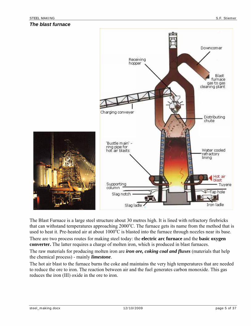
The blast furnace
The Blast Furnace is a large steel structure about 30 metres high. It is lined with refractory firebricks that can withstand temperatures approaching 2000oC. The furnace gets its name from the method that is used to heat it. Pre-heated air at about 1000oC is blasted into the furnace through nozzles near its base.
There are two process routes for making steel today: the electric arc furnace and the basic oxygen converter. The latter requires a charge of molten iron, which is produced in blast furnaces.
The raw materials for producing molten iron are iron ore, coking coal and fluxes (materials that help the chemical process) - mainly limestone.
The hot air blast to the furnace burns the coke and maintains the very high temperatures that are needed to reduce the ore to iron. The reaction between air and the fuel generates carbon monoxide. This gas reduces the iron (III) oxide in the ore to iron.

STEEL MAKING S.F. Stiemer
steel_making.docx 12/10/2009 page 6 of 37
Refining iron The metal that leaves the Blast Furnace contains between 4% and 5% of carbon. This much carbon makes a very hard but brittle metal which is not of much use. The next step in the production of steel is to reduce the levels of carbon and other impurity elements in the hot metal.
Materials The iron ores arrive in a number of forms: lumps of ore in the form in which they were mined; fine-sized iron ores; and pellets - fine ores which have been processed to stick together to form hard spheres of iron ore. The coals and ores are transported by conveyor belt or rail to stockyards where they are stored and carefully blended.
Blended coal is first heated in coke ovens to produce coke. This process is known as carbonisation. The gas produced during carbonisation is extracted and used for fuel elsewhere in the steelworks. Other by-products (such as tar and benzole) are also extracted for further refining and sale. Once carbonised, the coke is pushed out of the ovens and allowed to cool.
Fine-sized ore is first mixed with coke and fluxes and heated in a sinter plant. This is a continuous moving belt on which the coke is ignited. The high temperatures generated fuse the ore particles and fluxes together to form a porous clinker called sinter. The use of sinter in the blast furnace helps make the ironmaking process more efficient.
Iron ore lumps and pellets, coke, sinter and possibly extra flux are carried to the top of the blast furnace on a conveyor or in skips and then tipped, or charged, into the furnace. Hot air (900 degrees C etc) is blasted into the bottom of the furnace through nozzles called tuyeres. The oxygen in the air combusts with the coke to form carbon monoxide gas, and this generates a great deal of heat. Frequently oil or coal is injected with the air, which enables less (relatively expensive) coke to be used. The carbon monoxide flows up through the blast furnace and removes oxygen from the iron ores on their way down, thereby leaving iron. The heat in the furnace melts the iron, and the resulting liquid iron (or hot metal as it is called in the industry) is tapped at regular intervals by opening a hole in the bottom of the furnace and allowing it to flow out. The fluxes combine with the impurities in the coke and ore to form a molten slag, which floats on the iron and is also removed (tapped) at regular intervals.
The hot metal flows into torpedo ladles. These are specially constructed railway containers which transport iron, still in liquid form, to the steel furnace.
The process described above goes on continuously for ten years or more. (This is known as a campaign.) If the furnace were allowed to cool, damage could be caused to its lining of refractory bricks as a result of their contracting as they cooled. Eventually the refractory brick linings are worn away, and at that stage the process is stopped and the furnace relined with new bricks, ready to begin its next campaign.
The iron produced by the blast furnace has a carbon content of 4 to 4.5% as well as a number of other "impurities". This makes it relatively brittle. Steelmaking refines iron, amongst other things by reducing its carbon content, to make it a stronger and more manipulable product.

STEEL MAKING S.F. Stiemer
steel_making.docx 12/10/2009 page 7 of 37
The Basic Oxygen Converter
The BOS (Basic Oxygen Steelmaking) process is the major modern process for making bulk steels. Apart from special quality steels (such as stainless steel), all flat products (see relevant information page), and long products (see relevant information page) over a certain size, are rolled from steel made by the BOS process.
The BOS vessel is first tilted to allow materials to be tipped into it (charged). Scrap steel is first charged into the vessel, followed by hot metal (liquid iron) from the blast furnace. A water-cooled lance is lowered into the vessel through which very pure oxygen is blown at high pressure. The oxygen, through a process known as oxidation, combines with the carbon, and with other unwanted elements, separating them from the metal, leaving steel. Lime-based fluxes (materials that help the chemical process) are charged, and they combine with the "impurities" to form slag.
The main gas formed as a by-product of the oxidation process is carbon-monoxide, and this is sometimes collected for use as a fuel elsewhere in the works.
A careful balance between the amounts of hot metal and scrap charged into the converter is maintained as a means of controlling the temperature and to ensure that steel of the required specification is produced. After a sample has been taken to check that the chemical content of the steel is correct, the vessel is again tilted to allow the molten steel to flow out. This is known as tapping. The steel is tapped into a ladle, in which secondary steelmaking frequently takes place. During tapping small quantities of other metals and fluxes are often added to control the state of oxidation and to meet customer requirements for particular grades of steel.
Finally the vessel is turned upside down and the slag tipped out into a container. Steelmaking slag is sometimes recycled to make road building materials.
The modern BOS vessel makes up to 350 tonnes of steel at a time, and the whole process takes about 40 minutes.

STEEL MAKING S.F. Stiemer
steel_making.docx 12/10/2009 page 8 of 37
The basic oxygen sequence 1. Charging the furnace: The BOS converter is charged first with scrap. This is used as a coolant.
It helps to control the very high temperatures produced by the violently exothermic reactions in the furnace. After the scrap, three or four times as much hot metal (up to 300 tonnes) is poured into the furnace from a ladle.
2. Blowing: After charging, the furnace is blown by blasting oxygen through a lance that is lowered into the molten metal. The furnace needs no heating because the oxygen combines very exothermically with the impurity elements, carbon, silicon, manganese and phosphorus. Carbon is oxidised to carbon monoxide and much of the carbon in the metal escapes as this gas. The other impurity elements also form oxides. These are acidic and are separated from the metal by adding basic calcium oxide (lime) to the furnace. This combines with the oxides and removes silicon, manganese and phosphorus in a slag.
3. Tapping the furnace: After the blow has continued for about 20 minutes, the metal is sampled. Its composition at this stage is shown in Bar Chart. The BOS process is now complete and the furnace can be tapped. Steel is run out of the taphole into a ladle, separating it from the lighter slag, which is later emptied as waste.
The Electric Arc Furnace
The Electric Arc Furnace (EAF) offers an alternative method of bulk steel manufacture. It makes steel from what would otherwise be unsightly and environmentally damaging scrap metals. It also consumes much less energy than the BOS furnace. Every tonne of EAF steel uses about 7.4 GJ of energy compared with about 16.2 GJ for every tonne of BOS steel.
The electric arc furnace (EAF) (together with the basic oxygen vessel) is one of the two modern ways of making steel. EAFs are used to produce special quality steels (steels alloyed with other metals) and some ordinary (non-alloy) quality steels - the lighter long products such as those used for reinforcing concrete.
STEEL MAKING S.F. Stiemer
steel_making.docx 12/10/2009 page 9 of 37
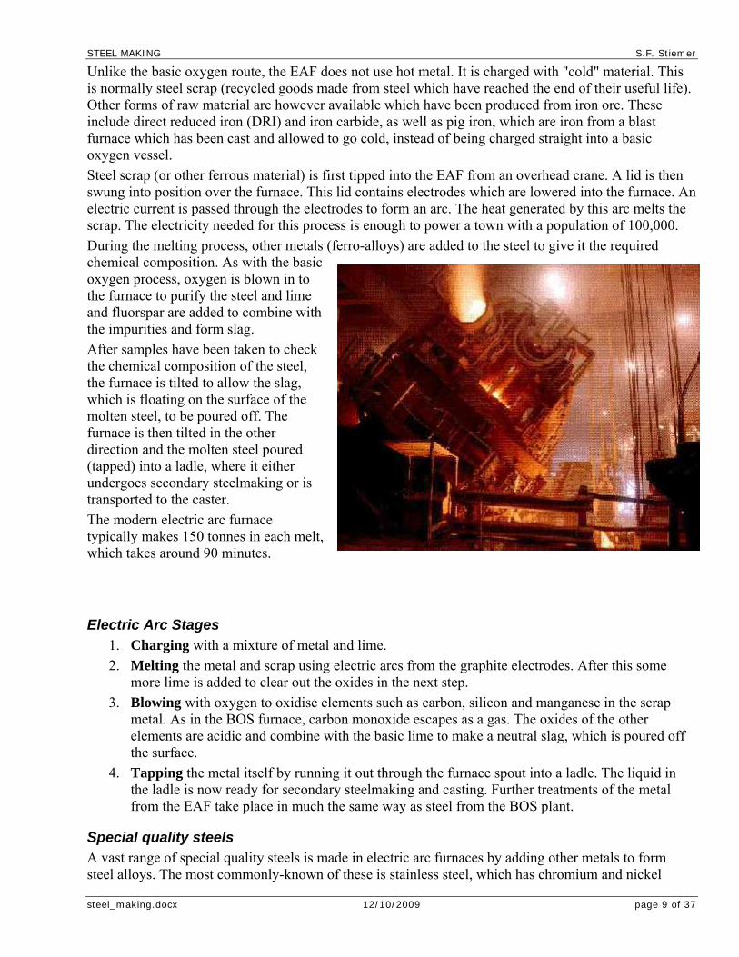
Unlike the basic oxygen route, the EAF does not use hot metal. It is charged with "cold" material. This is normally steel scrap (recycled goods made from steel which have reached the end of their useful life). Other forms of raw material are however available which have been produced from iron ore. These include direct reduced iron (DRI) and iron carbide, as well as pig iron, which are iron from a blast furnace which has been cast and allowed to go cold, instead of being charged straight into a basic oxygen vessel.
Steel scrap (or other ferrous material) is first tipped into the EAF from an overhead crane. A lid is then swung into position over the furnace. This lid contains electrodes which are lowered into the furnace. An electric current is passed through the electrodes to form an arc. The heat generated by this arc melts the scrap. The electricity needed for this process is enough to power a town with a population of 100,000.
During the melting process, other metals (ferro-alloys) are added to the steel to give it the required chemical composition. As with the basic oxygen process, oxygen is blown in to the furnace to purify the steel and lime and fluorspar are added to combine with the impurities and form slag.
After samples have been taken to check the chemical composition of the steel, the furnace is tilted to allow the slag, which is floating on the surface of the molten steel, to be poured off. The furnace is then tilted in the other direction and the molten steel poured (tapped) into a ladle, where it either undergoes secondary steelmaking or is transported to the caster.
The modern electric arc furnace typically makes 150 tonnes in each melt, which takes around 90 minutes.
Electric Arc Stages 1. Charging with a mixture of metal and lime.
2. Melting the metal and scrap using electric arcs from the graphite electrodes. After this some more lime is added to clear out the oxides in the next step.
3. Blowing with oxygen to oxidise elements such as carbon, silicon and manganese in the scrap metal. As in the BOS furnace, carbon monoxide escapes as a gas. The oxides of the other elements are acidic and combine with the basic lime to make a neutral slag, which is poured off the surface.
4. Tapping the metal itself by running it out through the furnace spout into a ladle. The liquid in the ladle is now ready for secondary steelmaking and casting. Further treatments of the metal from the EAF take place in much the same way as steel from the BOS plant.
Special quality steels A vast range of special quality steels is made in electric arc furnaces by adding other metals to form steel alloys. The most commonly-known of these is stainless steel, which has chromium and nickel

STEEL MAKING S.F. Stiemer
steel_making.docx 12/10/2009 page 10 of 37
added to form corrosion-resistant steel. There are very many others however: the very hard steels used to make machine tools, the steels specially-formulated to make them suitable for engineering, steels developed to survive for decades the hostile environment of nuclear reactors, light but strong steels used in aerospace, extra tough steels for armour plating - to name but a few.
Minimills In a large country such as the USA, the traditional centres of the steelmaking industry can be a very long way from their markets. These markets often exist in heavily populated, manufacturing regions that generate large volumes of scrap metal. In areas like this, steelmaking plants have developed that do not rely on a supply of Blast Furnace iron. They are called minimills. Minimills make only a small number of steel products for mostly local markets. They convert local scrap metal to steel in Electric Arc Furnaces before further processing takes place in secondary steelmaking and continuous casting facilities. About 25% of steelmaking plants in the USA are minimills. They are very efficient and relatively cheap to build compared to a traditional iron and steelworks.
In some parts of the world, minimills are developing alongside newer methods of iron production. The absence or shortage of coking coal in these areas has led to a search for new ways of reducing iron ore. Natural gas or crude oil products can be used instead of coke to generate the gas that reduces the ore. The reducing gas that is made in this way is usually a mixture containing carbon monoxide and hydrogen. To make iron, this mixed reducing gas is typically blown at about 800oC through a tall furnace that is packed with ore. At this temperature iron does not melt and the furnace product is a solid known as directly reduced iron (DRI). This metal can be processed in the Electric Arc Furnace in the same way as scrap metal.
Types of steel Steels are a large family of metals. All of them are alloys in which iron is mixed with carbon and other elements. Steels are described as mild, medium- or high-carbon steels according to the percentage of carbon they contain, although this is never greater than about 1.5%.
Type of steel Percentage of carbon
Mild steel Up to 0.25%
Medium carbon steel 0.25% to 0.45%
High carbon steel 0.45% to 1.50%
Chemistry
Reactivity of metals Iron is a moderately reactive metal which joins readily with non-metals such as oxygen. This is why we do not find pure iron in the Earth’s crust. Instead it is found as an ore, in which iron is chemically combined with oxygen or other non-metals. Most workable iron ores are rich in iron (III) oxide, Fe2O3. Making iron by removing oxygen from the ore is the first step in the manufacture of steel.
Reduction and oxidation Removing oxygen chemically from a substance is called reduction. The industrial production of iron involves reducing iron (III) oxide in a Blast Furnace. Most of the iron (III) oxide is reduced using carbon monoxide gas. This gas is a reducing agent which takes the oxygen away from iron (III) oxide.

STEEL MAKING S.F. Stiemer
steel_making.docx 12/10/2009 page 11 of 37
iron (III) oxide + carbon monoxide iron + carbon dioxide Fe2O3(s) + 3 CO(g) 2 Fe(l) + 3 CO2(g)
Notice that carbon monoxide gas in this reaction is changing into carbon dioxide. We call this oxidation, because each molecule of carbon monoxide gains an oxygen atom. The overall process is a redox reaction, in which iron (III) oxide is reduced and carbon monoxide is oxidised.
Another redox reaction Not all the iron (III) oxide is reduced by carbon monoxide in this way. Between 20% and 30% of the iron is produced by direct reduction, when the ore is directly reduced by carbon.
iron (III) oxide + carbon iron + carbon monoxide Fe2O3(s) + 3 C(g) 2 Fe(l) + 3 CO(g)
In this reaction unburned carbon, not carbon monoxide, is the reducing agent. This carbon is oxidised to form carbon monoxide.
Oxidising iron Iron is a moderately reactive metal and is easily changed back into its oxide. This is what happens during rusting. This everyday reaction affects most kinds of iron and steel. Steels are usually treated in some way during their manufacture to slow down the rate at which rusting takes place.
Iron is changed into steel by blowing oxygen through the molten metal from the Blast Furnace. This oxidises the impurities in the molten metal.
Reactions between acids and bases There are several reactions in the iron and steel making processes which involve acids and bases. One of the raw materials which are fed into the Blast Furnace is limestone, an almost pure form of calcium carbonate. Limestone decomposes in the hot furnace to give calcium oxide, which is a base.
calcium carbonate calcium oxide +carbon dioxide
CaCO3(s) CaO(s) + CO2(g)
Calcium oxide joins with acidic impurities in the ore, to make a salt. The biggest impurity is silica, a weak acid, which combines with calcium oxide to make calcium silicate, a salt which is formed as a molten slag.
Calcium oxide also plays an important part in the Basic Oxygen Steelmaking furnace. Here it helps to remove impurities such as phosphorus and sulphur from the steel. Phosphorus is a non-metal and produces an acidic oxide, P2O5. In the BOS furnace P2O5 combines with the basic calcium oxide to make calcium phosphate. This forms part of a molten slag which collects on the surface of the molten metal
calcium oxide + silica calcium silicate
CaO(s) + SiO2(s) CaSiO3(l)
Endothermic and exothermic reactions Energy conservation and temperature control are important to the success of any large manufacturing industry. Some of the processes involved in the production of steel take in energy while others release energy. In the Blast Furnace, for example, the thermal decomposition of limestone takes in energy. Reactions which take in energy are endothermic. Other processes in the steel plant offset these energy losses.
STEEL MAKING S.F. Stiemer
steel_making.docx 12/10/2009 page 12 of 37
The Basic Oxygen Steelmaking furnace needs no heating at all because the reactions that take place in it are strongly exothermic. Such reactions release energy to their surroundings. In fact, the BOS reactions are so violently exothermic that a coolant must be used in the furnace to control the temperature.
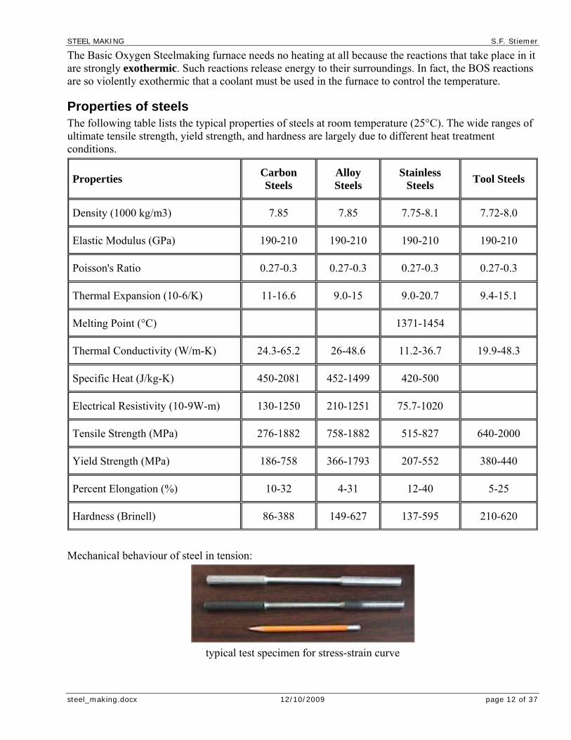
Properties of steels The following table lists the typical properties of steels at room temperature (25°C). The wide ranges of ultimate tensile strength, yield strength, and hardness are largely due to different heat treatment conditions.
Properties Carbon Steels
Alloy Steels
Stainless Steels
Tool Steels
Density (1000 kg/m3) 7.85 7.85 7.75-8.1 7.72-8.0
Elastic Modulus (GPa) 190-210 190-210 190-210 190-210
Poisson's Ratio 0.27-0.3 0.27-0.3 0.27-0.3 0.27-0.3
Thermal Expansion (10-6/K) 11-16.6 9.0-15 9.0-20.7 9.4-15.1
Melting Point (°C) 1371-1454
Thermal Conductivity (W/m-K) 24.3-65.2 26-48.6 11.2-36.7 19.9-48.3
Specific Heat (J/kg-K) 450-2081 452-1499 420-500
Electrical Resistivity (10-9W-m) 130-1250 210-1251 75.7-1020
Tensile Strength (MPa) 276-1882 758-1882 515-827 640-2000
Yield Strength (MPa) 186-758 366-1793 207-552 380-440
Percent Elongation (%) 10-32 4-31 12-40 5-25
Hardness (Brinell) 86-388 149-627 137-595 210-620
Mechanical behaviour of steel in tension:
typical test specimen for stress-strain curve

STEEL MAKING S.F. Stiemer
steel_making.docx 12/10/2009 page 13 of 37
stress-strain diagram for mild steel

STEEL MAKING S.F. Stiemer
steel_making.docx 12/10/2009 page 14 of 37
Secondary Steelmaking
stages of steel making
Increasingly today, steels after they have been tapped (poured) from the furnace undergo a further stage of processing called secondary steelmaking before the steel is cast. This applies to both the basic oxygen process route and to the electric arc furnace route.
The molten steel is tapped from the furnace into a ladle. A lid is placed over the ladle to conserve heat. A range of different processes is then available, such as stirring with argon, adding alloys, vacuum de-gassing or powder injection. The objective in all cases is to fine tune the chemical composition of the steel and/or to improve homogenisation of temperature (making sure that the steel is the same temperature throughout) and remove impurities. Ladle arc heating is a process used to ensure that the molten steel is at exactly the correct temperature for casting.

STEEL MAKING S.F. Stiemer
steel_making.docx 12/10/2009 page 15 of 37
Casting
Entrapment of non-metallic inclusions
The final stage of steelmaking is casting. Refractory shrouds are used during casting to prevent atmospheric exposure and therefore allow reactions to occur between oxygen and alloying elements in the molten steel resulting in inclusions being formed. Other practices are also used during casting which actively promote the removal of inclusions from the steel, thereby improving steel cleanness:
Electromagnetic slag detection in the exit port from the steelmaking ladle is used to prevent ladle top slag being carried over into the tundish and entrained in the inclusion population; as the steel level in the ladle falls during casting, there is a chance of ladle top slag being entrained in the steel flow through the exit port. If this happens the magnetic flux measured by detector coils changes and sends as signal which shuts off the steel flow from the ladle.
Flow from the tundish to the mould is controlled via a stopper rod or sliding gate mechanism which is linked to the metal lever detector in the mould. This stream is also shrouded by a refractory tube which is carefully designed to optimize flow conditions in the mould and promote conditions for any further inclusion flotation.
Continuous Casting Not that many years ago, molten steel used to be poured (teemed) into a large mould where it would be allowed to cool and solidify to form an ingot. The ingot was then put into an oven called a soaking pit, where it would be gently heated to the correct and uniform temperature. This red hot ingot would then be rolled in primary mills,

STEEL MAKING S.F. Stiemer
steel_making.docx 12/10/2009 page 16 of 37
in the first stage of its transformation into a usable steel product, into one of three forms of semi-finished product: a slab (a long, thick, flat piece of steel, with a rectangular cross-section), a bloom (a long piece of steel with a square cross-section) or a billet (like a bloom, but with smaller cross-section).
Nowadays this process has largely been superseded by the continuous casting process (concaster), although the ingot route is retained for certain applications where it is the most suitable way of producing the steel required. (Elsewhere this is not always the case: many of the steel industries of Eastern Europe still rely heavily on the old ingot route.)
In a continuous casting machine, molten steel is poured into a reservoir at the top of the machine. It passes at a controlled rate into a water cooled mould where the outer shell of the steel becomes solidified. The steel is drawn down into a series of rolls and water sprays, which ensure that it is both rolled into shape and fully solidified at the same time. At the end of the machine, it is straightened and cut to the required length. Fully formed slabs, blooms and billets emerge from the end of this continuous process.
Thus the concaster combines in a single process what previously took two separate processes. This is both highly energy-efficient and produces a better quality product.
The slabs, blooms or billets are then transported to the hot rolling mill for rolling into steel products which can be used by manufacturing industry.
Oxygen control At the tap of a steelmaking converter the steel has very high dissolved oxygen content. This oxygen must be removed before the steel is cast, otherwise carbon monoxide gas would be formed during solidification causing excessive porosity. To remove this oxygen sacrificial alloys are added to the molten steel during converter tapping; these additions react with the oxygen in the steel to form oxides, acting to reduce the 'free' oxygen content in the steel, these generally form solid/liquid oxides which remain in the steel as inclusions or float to the surface of the steel to form a slag layer (oxide inclusions are less dense than steel).
Removal of impurities In addition to high levels of oxygen, the crude steel tapped from the converter also contains impurities which are not desired in the final steel chemistry.
Modern primary and secondary steelmaking practices can reduce the level of these impurities to a very low level, but usually a residual impurity level remains. One of the trace elements that is present during the steel making process and is generally undesirable is sulphur. The presence of free sulphur in a steel product is detrimental to its properties, especially toughness.
Modern steel making processes and selection of raw materials means that the levels of sulphur present in a steel are very low. Any remaining sulphur can be removed through the use of alloying additions of manganese which reacts with the sulphur to form MnS. MnS inclusions are relatively soft, especially at elevated temperature, and can become elongated during hot rolling, forging or drawing processing.
The presence of elongated MnS inclusions in the rolled / forged / drawn steel can present a problem for the manufacturing / fabrication / finishing stage of steel processing. This is especially true for strip steels that are going to be deep drawn into drinks cans. The reason for this is that the deep drawing process occurs at room temperature where the MnS inclusions are no longer soft enough to deform. As the steel

STEEL MAKING S.F. Stiemer
steel_making.docx 12/10/2009 page 17 of 37
blank is drawn into the can shape the wall thickness of the can is reduced to ~6 µm. MnS inclusions can be several microns in length and this can cause failure of the can through tearing. Any increase in can reject number will cost the manufacturer in terms of time retrieving the damaged can and revenue for the rejected can. This means that rejects from inclusions cannot be tolerated and extremely clean steels are required. This is achieved through precise control of the steel making stage of processing to ensure that there are virtually no MnS inclusions present in the steel destined to be strip steel used for making drinks cans. Also additions can be made to the steel which modify any MnS inclusions present to a composition which remains globular and does not deform to give long MnS stringers during steel rolling. Due to the increased costs associated with specifying such high levels of cleanness for this product grade of steel, other less stringent product grades are not specified to such a high level and MnS inclusions will be seen (although at a low level due to the general level of steel cleanness achievable today).
Inclusions for improved machinability Alloying elements can be added during secondary steelmaking specifically to modify the steel inclusion population. These alloys can be added as 'lump additions', but more commonly are injected into the steel. The choice of addition is highly dependant on the steel type being made, its processing conditions and final application.
One important aspect of this decision, is the amount of additional cost which can be tolerated by the customer associated with the treatment required to give enhanced product performance (additions for inclusion modification are often highly expensive).
Some commonly added materials and their role in modifying the steel inclusion population is outlined below:
• Sulphur
Sulphur can be added up to ~ 0.35 % by weight, and is one of the cheapest additions. It is used in free-cutting steels in combination with manganese additions, to give manganese sulphide inclusions which deform plastically during rolling and cutting; these elongated inclusions promote chip formation and breakup during subsequent machining. They also reduce cutting temperatures and tool wear.
• Lead
This metal is also added to free-cutting steels to improve machinability; the lead is deep injected into the steel (0.15 - 0.35%), requiring fume extraction to remove toxic lead vapour. The lead forms discrete particles in the steel structure on solidification, often present as tails on manganese sulphide inclusions. During machining the lead melts locally at the tool / workpiece interface acting as a lubricant and reducing tool wear.
• Tellurium
Is again deep injected in free-cutting steels to improve machinability (~ 0.1 wt%) and is commonly co-injected with lead; higher levels of tellurium cause cracking during hot working (it is also a very expensive alloy).
Tellurium is very toxic and therefore requires strict precautions to be taken during steelmaking. It is present as manganese telluride in the solid product and has a similar effect to lead. It also acts to modify the shape of manganese sulphide inclusions from an elongated to globular morphology.
• Bismuth
Often co-injected with lead and tellurium in free-cutting steels (~0.1 wt%). It has a similar effect to lead but it is a considerably more expensive addition.
• Selenium
STEEL MAKING S.F. Stiemer
steel_making.docx 12/10/2009 page 18 of 37
Selenium can be added up to a level of 0.15 wt% and modifies the shape of MnS inclusions.
• Calcium
Calcium is widely used in a number of different inclusion engineering applications, such as the following:
Calcium treatment of manganese sulphide inclusions gives species which remain globular during rolling. This treatment is used in steels such as pipe plate where MnS stringers can cause planes of weakness within the steel, along which lamellar tearing can occur (non-isotropic properties).
Treatment of hard, angular, abrasive alumina inclusions in aluminium deoxidised steels, gives calcium aluminate inclusions which are softer and globular at rolling temperatures, thereby improving the material's processing characteristics.
Some inclusions found in steel have a tendency to block the nozzles in continuous casting machines, resulting in casting being terminated prematurely, lost output and increased costs. Calcium treatment can be used to modify the inclusion population in steels with a propensity for blockage, to give low melting point species which will not clog the caster nozzles.
Ladle top slag Converter carryover slag and synthetic slag additions are two elements of the ladle steelmaking system that can be considered together, as they are the principal components which go to make up the 'Ladle Top Slag'. The ladle top slag floats on the surface of the steel in the ladle and has a profound impact on the inclusion population in the steel.
Converter carryover slag - during primary steel refining in the BOS / EAF converter, slag-making additions are made to form a slag which absorbs impurities from the steel (such as sulphur and phosphorus). During converter tapping, in addition to the crude steel tapped into the ladle, some converter slag is also carried over into the steelmaking ladle, hence the name 'carryover slag'. Since slag contains impurities from primary refining, it would be very desirable to have zero slag carryover, as these impurities can revert to the steel in the ladle. However, some carryover is inevitable. Variable levels of carryover slag also cause undesirable variation in the ladle top slag composition, and so it is important to control both the consistency and level of slag carryover.
Synthetic Slag Additions - form the bulk of the ladle top slag (normally about 1 tonne). These additions are made to achieve an aim slag chemistry appropriate to the steel type being made and its manufacturing process route. Most synthetic slags are lime (CaO) based, but a wide range of compositions are employed to satisfy different metallurgical and operational needs. Roles of synthetic slag include inclusion engineering, desulphurisation and heat transfer during ladle re-heating.
The ladle top slag chemically interacts and is in equilibrium with the steel. In certain steels, the ladle top slag closely reflects steel inclusion population composition; thus by manipulating the ladle top slag composition, the inclusion composition can be controlled to a desirable chemistry. The slag, which is usually liquid also acts as a capture surface for inclusions which float out of the steel, and therefore promotes steel cleaning.
Poor slag control can also lead to poor steel cleanness. For example, in a steel alloyed with aluminium (Al 'killed'), if the ladle top slag is highly oxidised (high levels of FeO and MnO), then aluminium in the steel can react with 'oxygen' in the slag to form hard alumina inclusions in the steel which are detrimental to product properties.
Slag glaze During steel casting, the steelmaking ladle is emptied through a valve in the bottom of the ladle; as the ladle gradually empties, the ladle top slag coats and solidifies on the side walls of the ladle, and remains there once the ladle is empty. This is termed 'slag glaze' as it glazes the surface of the ladle walls.

STEEL MAKING S.F. Stiemer
steel_making.docx 12/10/2009 page 19 of 37
The next time the ladle is used, the steel tapped into the ladle interacts with the slag glaze in a similar way to the ladle top slag, influencing the steel inclusion population. Some of the glaze also re-melts and floats to the surface of the ladle and is incorporated in the ladle top slag.
Because of the interaction between steel and glaze and the resultant impact on the inclusion population, for some steels it is very important to ensure that the ladle glaze has the correct composition; this helps to ensure that inclusions of a desirable chemistry are formed.
To control the ladle glaze, it is necessary to carefully plan that the steel made in a ladle just before an inclusion critical steel grade, is of a certain composition and made using a specified ladle top slag (which forms the glaze on the inclusion critical cast).
Ladle stirring Molten steel can be stirred electromagnetically (EMS) or by gas bubbling during secondary steelmaking.
The principal purpose is to homogenize the steel with respect to both composition and temperature.
Stirring also has a major impact on the inclusion population.
Vigorous stirring can break the slag surface. This results in:
more inclusions / slag particles;
oxidation of the exposed molten steel.
Conversely, gentle stirring is widely used as a steel cleaning technique.
Stokes Law states that for spherical particles:
where
u is the terminal upward velocity of the inclusion
g is 9.81 m s-1
d is the inclusion diameter [m]
∂ρ is the difference in densities between the liquid steel and inclusion [kg m-3], and
η is the molten steel viscosity [N s m-2]
Vacuum treatment Vacuum treatment (generally called vacuum degassing) is a commonly used steelmaking process, used for removing dissolved gases (e.g. hydrogen) from the steel. In this process, the steel is exposed to a vacuum which promotes transfer of dissolved gases from the liquid steel to gas phase.
Exposure of steel to vacuum also promotes reaction between oxygen and carbon dissolved in the steel to produce carbon monoxide, by shifting the equilibrium conditions. Similar to ladle arc heating, this has the effect of chemically reducing the ladle system.
In this way, alumina found in refractories and the ladle top slag can be reduced to give dissolved aluminium in the steel:
In Vacuum: Al2O3 2Al + 3O
When the vacuum is removed, the dissolved aluminium can react with inclusions in the steel to increase their alumina content, and in some steels inclusions detrimental to product properties can be formed in this way. For such steels, a lower vacuum is used during degassing to avoid this problem.

STEEL MAKING S.F. Stiemer
steel_making.docx 12/10/2009 page 20 of 37
Hot Rolling Semi-finished products called blooms, billets and slabs are transported from the steelmaking plant to the rolling mills. In many plants steelmaking and rolling are both carried out on the same site.
Steel products can be classified into two basic types according to their shape: flat products and long products. Slabs are used to roll flat products, while blooms and billets are mostly used to roll long products. Billets are smaller than blooms, and therefore are used for the smaller type of long product.
Semi-finished products are first heated in a re-heat furnace until they are red hot (around 12000 C). On all types of mill the semi-finished products go first to a roughing stand. A stand is a collection of steel rolls (or drums) on which pressure can be applied to squeeze the hot steel passing through them, and arranged so as to form the steel into the required shape. The roughing stand is the first part of the rolling mill. The large semi-finished product is often passed backwards and forwards through it several times. Each pass gradually changes the shape and dimension of the steel closer to that of the required finished product.
Plate mills Slabs are used to make plate. Typically, after leaving the plate mill's roughing stand, they are passed through a finishing stand. This is a reversing mill: like on the roughing stand, the steel is passed backwards and forwards through the mill. It is also turned 900 and rolled sideways at one stage during the process.
Plate is a large, flat piece of steel perhaps 10mm or 20mm thick (although it can be up to 50mm thick) and up to 5 metres wide. It is used for example to make the hulls and decks of ships or to make large tanks and boilers. It can also be rolled up and welded to form a large steel tube, used for oil and gas pipelines.
Strip mills Slabs are also used to make steel strip, normally called hot rolled coil. After leaving the roughing stand, the slab passes continuously through a series of finishing stands which progressively squeeze the steel to make it thinner. As the steel becomes thinner, it also of course becomes longer, and starts moving faster. And because the single piece of steel will be a whole range of different thicknesses along its length as each section of it passes through a different stand, different parts of the same piece of steel are travelling at different speeds. This requires very close control of the speeds at which each individual stand rolls; and the entire process is controlled by computer. By the time it reaches the end of the mill, the steel is traveling at about 40 miles per hour. Finally the long strip of steel is coiled and allowed to cool.
Hot rolled strip is a flat product which has been coiled to make storage and handling easier. It is a lot thinner than plate, typically a few millimetres thick, although it can be as thin as 1mm. Its width can vary from 150mm to nearly 2 metres. It frequently goes through further stages of processing such as cold rolling and is also used to make tubes (smaller tubes than those made from plate ).

STEEL MAKING S.F. Stiemer
steel_making.docx 12/10/2009 page 21 of 37
Long product mills Blooms and billets are used to make long products. After leaving the roughing stand, the piece of steel passes through a succession of stands which do not just reduce the size of the steel, but also change its shape. In a universal mill, all faces of the piece of steel are rolled at the same time. In other mills, only two sides of the steel are rolled at any one time, the piece of steel being turned over to allow the other two sides to be rolled.
Long products are so called because they come off the mill as long bars of steel. They are however produced in a vast range of different shapes and sizes. They can have cross-sections shaped like an H or I (called joists, beams and columns), a U (channels) or a T. These types of steel "section" are used for construction. Bars can have cross-sections the shape of squares, rectangles, circles, hexagons, angles. These bars can also be used for construction, but many types of bar are also used for engineering purposes. Rod is coiled up after use and is used for drawing into wire or for fabricating into products used to reinforce concrete buildings, as are some types of bar.
Other types of long product include railway rails and piling. Some long product mills make unique shapes of steel to a customer's individual specification. These are known as special sections.
Cooling In all rolling processes, cooling the steel is a critical factor. The speed at which the rolled product is cooled will affect the mechanical properties of the steel. Cooling speed is controlled normally by spraying water on the steel as it passes through and/or leaves the mill, although occasionally the rolled steel is air-cooled using large fans.
Further processing Hot rolled products can undergo many forms of further processing before they are finally used to make an end-product (such as a steel-framed building or a consumer product). Such processing includes:
Fabricating. Steel sections are cut, welded and otherwise prepared to form the steel frame of a building. Rods and bars are similarly cut and shaped to form the steel reinforcement for concrete buildings.
Cutting and slitting. Service centres cut steel into many complex shapes.
Profiling. Sheet steel may be pressed into the correct shape for crash barriers or the cladding of buildings (known as profiling).
Cold Rolling & Drawing
After hot rolling, many steel products undergo a further processing in the cold state. This stage of processing does not alter the shape of the steel product, but it does reduce it in thickness and significantly improve its performance characteristics.

STEEL MAKING S.F. Stiemer
steel_making.docx 12/10/2009 page 22 of 37
Hot rolled coil is commonly cold rolled (also known as cold reduced). The strip is first de-coiled (uncoiled) and then passes through a series of rolling mill stands which apply pressure to the strip and progressively reduce its thickness - down to as low as 0.15 mm. The strip is then recoiled. Cold rolling processes are also used to improve the surface quality of the steel. Cold rolling also has the effect of hardening steel, so cold reduced strip is subsequently annealed: a process of very carefully controlled heating and cooling to soften it.
Cold reduced strip and sheet is able to withstand subsequent forming and pressing operations without the steel cracking. The elaborate shapes used to make car bodies are pressed out of cold reduced sheets. Very thin cold reduced sheet (known also as blackplate), after coating with a thin layer of tin, is used to make food and drink cans. So sophisticated have modern steelmaking and rolling techniques become that it is now possible to press the shape
of the complete can (bottom and sides) from sheet steel, leaving only the lid to be sealed on after filling. Many drinks cans are formed in this way.
Another form of cold processing is cold drawing. Steel rod is dragged at pressure (drawn) through a series of dies which progressively reduce the rod's circumference to produce wire. The drawing process substantially increases the steel's tensile strength - steel wires can be spun into huge ropes strong enough to support the world's largest suspension bridges.
Coating Most steels when exposed to air will gradually rust. (This does not apply to all steels: stainless steel for example was invented - in Sheffield - specifically to resist rust.) Steel has therefore always been covered - frequently painted for example - by its users in order to protect it. Nowadays the steelmaker can improve steel's corrosion resistance by coating it in the factory prior to delivery to the end-user. A wide range of different coatings is available, including:
Zinc coating, normally called galvanizing. The zinc can be applied either electrolytically (which gives a thinner coating) or by dipping the steel in a bath of molten zinc. Much of the sheet used to produce car bodies is zinc coated. This has enabled thinner steels to be used for car bodies, thus saving weight and improving fuel consumption. (Without this coating, the thinner steels would have rusted, shortening the car's life.) Wire is also frequently galvanized to extend the product's life.
STEEL MAKING S.F. Stiemer
steel_making.docx 12/10/2009 page 23 of 37
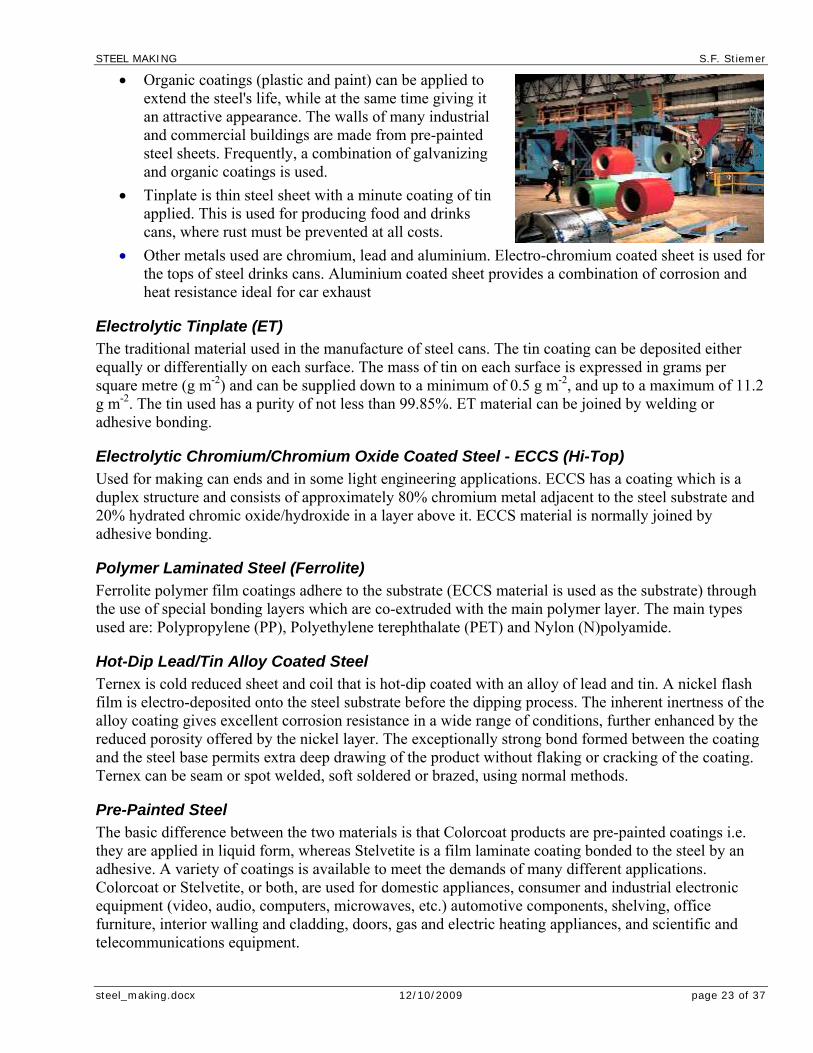
Organic coatings (plastic and paint) can be applied to extend the steel's life, while at the same time giving it an attractive appearance. The walls of many industrial and commercial buildings are made from pre-painted steel sheets. Frequently, a combination of galvanizing and organic coatings is used.
Tinplate is thin steel sheet with a minute coating of tin applied. This is used for producing food and drinks cans, where rust must be prevented at all costs.
Other metals used are chromium, lead and aluminium. Electro-chromium coated sheet is used for the tops of steel drinks cans. Aluminium coated sheet provides a combination of corrosion and heat resistance ideal for car exhaust
Electrolytic Tinplate (ET) The traditional material used in the manufacture of steel cans. The tin coating can be deposited either equally or differentially on each surface. The mass of tin on each surface is expressed in grams per square metre (g m-2) and can be supplied down to a minimum of 0.5 g m-2, and up to a maximum of 11.2 g m-2. The tin used has a purity of not less than 99.85%. ET material can be joined by welding or adhesive bonding.
Electrolytic Chromium/Chromium Oxide Coated Steel - ECCS (Hi-Top) Used for making can ends and in some light engineering applications. ECCS has a coating which is a duplex structure and consists of approximately 80% chromium metal adjacent to the steel substrate and 20% hydrated chromic oxide/hydroxide in a layer above it. ECCS material is normally joined by adhesive bonding.
Polymer Laminated Steel (Ferrolite) Ferrolite polymer film coatings adhere to the substrate (ECCS material is used as the substrate) through the use of special bonding layers which are co-extruded with the main polymer layer. The main types used are: Polypropylene (PP), Polyethylene terephthalate (PET) and Nylon (N)polyamide.
Hot-Dip Lead/Tin Alloy Coated Steel Ternex is cold reduced sheet and coil that is hot-dip coated with an alloy of lead and tin. A nickel flash film is electro-deposited onto the steel substrate before the dipping process. The inherent inertness of the alloy coating gives excellent corrosion resistance in a wide range of conditions, further enhanced by the reduced porosity offered by the nickel layer. The exceptionally strong bond formed between the coating and the steel base permits extra deep drawing of the product without flaking or cracking of the coating. Ternex can be seam or spot welded, soft soldered or brazed, using normal methods.
Pre-Painted Steel The basic difference between the two materials is that Colorcoat products are pre-painted coatings i.e. they are applied in liquid form, whereas Stelvetite is a film laminate coating bonded to the steel by an adhesive. A variety of coatings is available to meet the demands of many different applications. Colorcoat or Stelvetite, or both, are used for domestic appliances, consumer and industrial electronic equipment (video, audio, computers, microwaves, etc.) automotive components, shelving, office furniture, interior walling and cladding, doors, gas and electric heating appliances, and scientific and telecommunications equipment.

STEEL MAKING S.F. Stiemer
steel_making.docx 12/10/2009 page 24 of 37
Hot-Dip Zinc-Coated Steel Galvatite is the brand name of an extensive range of hot-dip zinc and iron/zinc alloy coated steels produced to conform to BS EN 10142 & BS EN 10147 in sheet and coil. Galvatite might be used for automotive wheel trim and wheel cavity panels.
Hot-Dip Iron-Zinc Alloy Coated Steel (Galvannealed Steel) This is a derivative of the hot-dip zinc-coated steel, produced by in-line annealing (galvannealing) after coating. This coating is used for automotive side body panels and boot panels and is popular with car makers as it offers the best combination of corrosion protection, formability, weldability, paintability and cost.
Hot-Dip Zinc/Aluminium Alloy Coated Steel Zalutite is steel that is hot-dip coated with an alloy composed primarily of zinc (43.5%) and aluminium (55%). The mixed coating provides increase corrosion protection compared to zinc alone.
Electro-Zinc Coated Steel Zintec, a electro-zinc coated steel sheet and coil, offers a number of advantages over ordinary uncoated mild steel. Zintec's corrosion resistance protects the steel in transit, in storage, during the production process, and in the finished product. Zintec might be used for automotive bonnets.
Zinc-Nickel Alloy Electro-Coated Steel (Nizec) Nizec is high quality cold reduced steel sheet and coil, electrolytically coated with a uniform, tightly adherent alloy of 87% zinc and 13% nickel (approximate percentages by mass). It is a versatile material which can improve product quality and durability. Under conventional salt spray and cyclic corrosion testing, Nizec gives 2-4 times the corrosion resistance of a pure electro-zinc coating of the same thickness. Its coating offers good resistance to galling damage under severe forming and drawing conditions and the surface finish is excellent for painting. Nizec might be used for automotive side body panels and boot panels.
Inherent corrosion resistance Although strictly NOT a coating, corrosion resistance can be imparted to steels by the addition of suitable amounts of chromium.
Fabrication
Weldability A measure of whether a steel can be easily welded is to determine the carbon equivalent (Cequiv or CD
equiv) of the steel. There are a number of different equations that can be used for this, the most appropriate depends on the type of steel being considered. For low alloy C-Mn steels with a ferrite + pearlite structure the appropriate equation is:
(alloying additions in wt%). For modern low carbon steels then we need to use:
(alloying additions in wt%).
For the steel to be easily weldable then Cequiv needs to be less than about 0.4 or the CDequiv needs to be
less than about 0.25.

STEEL MAKING S.F. Stiemer
steel_making.docx 12/10/2009 page 25 of 37
There are a number of different welding techniques that can be used for steels. Selecting the most appropriate technique depends upon the final product, plate thickness, geometry of the weld required. Typical examples of welding procedures and their applications are given below:
Fusion welding Fusion welding involves a heat source and may involve the use of a filler material such as a consumable electrode or a wire fed into the weld pool. These processes also use a protective layer between the atmosphere and the molten metal, either in the form of gas shielding or a flux which melts to give a viscous slag on the weld metal that eventually solidifies and can be removed. There are several different types of fusion welding processes that can be used. The table below gives some typical applications for the different procedures and the typical characteristics of technique.
Cost Cleanness of the weld
HAZ width
Level of automation
Thickness of plate
Comments and typical applications
Manual Metal Arc (MMA)
Low Poor - OK
5 - 6 mm
Not any - multipass
Only use for relatively short runs, for example car repair welds, small repair welds on bridges, oil rigs etc.
Submerged arc welding (SAW)
Medium Poor 7 - 10 mm
Very high any - multipass
Only use horizontally, used for high production runs for example pipelines.
Metal inert gas (MIG)
Low - Med
OK 3 - 4 mm
Medium any - multipass
Used for production runs on thinner sections than SAW
Tungsten inert gas (TIG)
Low - Med
Good 2 - 3 mm
Medium Any - multipass
Used for similar applications as MIG but for longer production runs
Laser Very high
Very good
< 0.5 mm for 12 mm thick plate
Very high up to 30 mm
Used for reasonably higher specification welds, becoming more widespread as cost comes down, for example automotive bodies. Low distortion process, requires good fit up no filler wires (reduces cost).
Electron Beam
Very high
Very good
< 0.5 mm for 12 mm thick plate
Low up to 250 mm
Requires a vacuum, very expensive, used in aerospace industry predominantly can be used for welding Al, Ti, Cu, stainless steels and reactive metals. Low distortion process, requires good fit up no filler wires (reduces cost).

STEEL MAKING S.F. Stiemer
steel_making.docx 12/10/2009 page 26 of 37
Spot welding Resistance spot welding is used extensively to join strip steels during car body assembly. Strip steels typically have low Cequiv values and are therefore relatively easily welded. Problems can arise for pre-painted strip and zinc coated strip. Resistance spot welding involves the two parts being clamped together between two electrodes and a large electric current being passed through them. The material between the electrodes heats up, yields and is squeezed together. It then melts, destroying the interface between the parts. The current is switched off and the 'nugget' of molten material solidifies forming the joint.
Friction welding Friction welding is used in the automotive industry to join steering columns and axles. The process involves rotating one component at high speed against another to generate heat. Once sufficiently hot rotation is ceased and the joint is forged. There are several variants of friction welding and whilst it is usual for at least one of the components to rotate a method of butt welding plates by linear friction welding is available. Size restrictions are related to the capacity of the equipment in generating sufficient torque.
Some of the end-uses of steel
Bridges Suspension bridges are "hung" using steel ropes. These are very strong, thick ropes spun using hundreds or even thousands of steel wires. Often these wires are of different shaped cross-sections designed to fit together for optimum strength
The decking (or "floor") of bridges are made either from steel plate, or from concrete reinforced with steel rods. Steel beams, joists, columns or tubes (both round and rectangular) are used for a variety of purposes: for piers or for supports for example. Steel piling may be used to support the bridge's foundations. Safety barriers and handrails will probably also be made from a variety of different types of steel. Tubes can be welded together to form railings. Crash barriers are made from precisely-tensioned steel wire, or from steel sheet that has been profiled into a "corrugated" shape. Lighting columns can be made from welded steel tubes. Even the road signs are made from steel sheet.
Engineering Steel bars are often used for engineering purposes. They come in a huge range of different shapes, sizes and qualities designed to suit the end use.
Some steels have lead added to them, to make them easier to engineer, saving time and energy for the steel user. These are known as free-cutting steels. You will find them in components under the bonnets of cars and in many
household electrical or mechanical goods.
Other steels (known as tool steels) have a special alloy content that makes them ideal for manufacturing the tools used to machine free-cutting steels.
Gears, engines, electrical motors, hydraulic systems, power generation (nuclear, oil, gas, coal, wind, wave) are just a few of the many engineering applications of steel.
STEEL MAKING S.F. Stiemer
steel_making.docx 12/10/2009 page 27 of 37
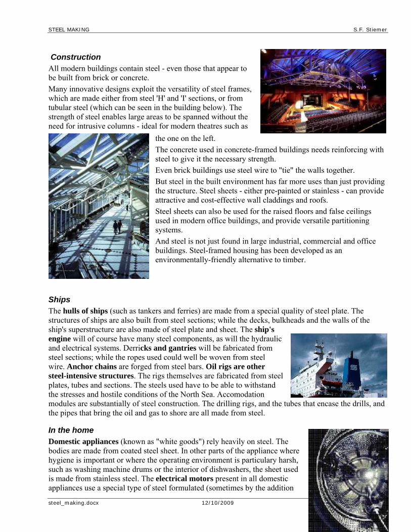
Construction All modern buildings contain steel - even those that appear to be built from brick or concrete.
Many innovative designs exploit the versatility of steel frames, which are made either from steel 'H' and 'I' sections, or from tubular steel (which can be seen in the building below). The strength of steel enables large areas to be spanned without the need for intrusive columns - ideal for modern theatres such as
the one on the left.
The concrete used in concrete-framed buildings needs reinforcing with steel to give it the necessary strength.
Even brick buildings use steel wire to "tie" the walls together.
But steel in the built environment has far more uses than just providing the structure. Steel sheets - either pre-painted or stainless - can provide attractive and cost-effective wall claddings and roofs.
Steel sheets can also be used for the raised floors and false ceilings used in modern office buildings, and provide versatile partitioning systems.
And steel is not just found in large industrial, commercial and office buildings. Steel-framed housing has been developed as an environmentally-friendly alternative to timber.
Ships The hulls of ships (such as tankers and ferries) are made from a special quality of steel plate. The structures of ships are also built from steel sections; while the decks, bulkheads and the walls of the ship's superstructure are also made of steel plate and sheet. The ship's engine will of course have many steel components, as will the hydraulic and electrical systems. Derricks and gantries will be fabricated from steel sections; while the ropes used could well be woven from steel wire. Anchor chains are forged from steel bars. Oil rigs are other steel-intensive structures. The rigs themselves are fabricated from steel plates, tubes and sections. The steels used have to be able to withstand the stresses and hostile conditions of the North Sea. Accomodation modules are substantially of steel construction. The drilling rigs, and the tubes that encase the drills, and the pipes that bring the oil and gas to shore are all made from steel.
In the home Domestic appliances (known as "white goods") rely heavily on steel. The bodies are made from coated steel sheet. In other parts of the appliance where hygiene is important or where the operating environment is particulary harsh, such as washing machine drums or the interior of dishwashers, the sheet used is made from stainless steel. The electrical motors present in all domestic appliances use a special type of steel formulated (sometimes by the addition

STEEL MAKING S.F. Stiemer
steel_making.docx 12/10/2009 page 28 of 37
of silicon) to give the required electrical properties. But steel is not just used in kitchen appliances. Other "higher-tech" appliances, such as computers and video recorders, rely on the strength of steel sheet to provide their robust casings.
Cars Cold reduced steel sheet is used to make the bodies of cars. These days, for applications that are prone to corrosion, zinc coated (galvanised) steel sheets are used - frequently with additional organic coatings (pre-painted). Far thinner steel sheets are used today, that retain the strength inherent in steel but by weighing less result in fuel savings for the driver. The use of zinc and other coatings to prevent corrosion means that these steels last longer in use than the thicker steels used in earlier generations of cars.
Steel sections form the sub-frame and safety cage - where steel's strength comes into its element in providing protection.
Engineering steels are of course used in many of the engine and transmission components - as well as in the cooling, braking, air conditioning and heating etc systems.
Electrical steels are present in the dozens of different motors used in the modern car.
Steel wire reinforces tires to give them the strength needed for today's driving conditions and speeds.
The car is of course just one example. Steel plays a vital role in all transport systems and vehicles: trains and urban transit systems, and the tracks they run on; buses; bicycles; lorries; cranes and earth moving machinery; boats and aeroplanes. Steel helps the world keep moving.

STEEL MAKING S.F. Stiemer
steel_making.docx 12/10/2009 page 29 of 37
Strength of Steel The main contributions to the strength of steel come from the effects of :
grain size
microstructure
solid solution strengthening
precipitates
dislocations
These factors are controlled by the chemistry of the steel and the processing route used to produce the final component. All of these aspects need to be taken into account when selecting or designing a steel for a given application.
For ferrite and pearlite steels relationships between yield /tensile strength and various compositional and microstructural factors have been developed. These are useful in that they show general characteristics, although they are unable to incorporate all factors that influence strength in modern steels, for example precipitation strengthening. Examples of these relationships are given below:
Yield Strength (MPa) = 53.9 + 32.3 Mn + 83.2 Si + 354 Nf + 17.4 d-1/2
Ultimate Tensile Strength (MPa) = 294 + 27.7 Mn + 83.2 Si + 3.85 pearlite % + 7.7 d-1/2
Alloying addition in wt%, d is the ferrite grain size in mm, Nf is the free nitrogen content.
Austenite: The solid solution of carbon in gamma (face centered cubic) iron.
Bainite: An acicular aggregate of ferrite and carbide particles formed when austenite is transformed on cooling at temperatures in the intermediate (200-450oC) range, i.e. above the martensite and below the pearlite range.
Ferrite: The solid solution of carbon in body-centered cubic iron, a constituent of carbon steels. Pure iron up to 912 ºC has a bcc structure and is known as alpha ferrite. Between 1394 ºC and the melting point of iron the bcc structure is now known as delta ferrite. Also found in carbon steel.
STEEL MAKING S.F. Stiemer
steel_making.docx 12/10/2009 page 30 of 37
Martensite: The hard constituent produced when steel is cooled from the hardening temperature at a speed greater than its critical cooling rate. Martensite is an acicular phase when seen in the microstructure of steel.
Pearlite: A lamellar constituent of steel consisting of alternate layers of ferrite (alpha-iron) and cementite (iron Carbide Fe3C) and is formed on cooling austenite at 723oC. This produces a tough structure and is responsible for the mechanical properties of unhardened steel. When steel is cooled at the rate of about 400º C per minute austenite crystals change into pearlite (a fine lamellar structure of alternating platelets of ferrite and iron carbide) at about 727º C. Faster cooling produces martensite.
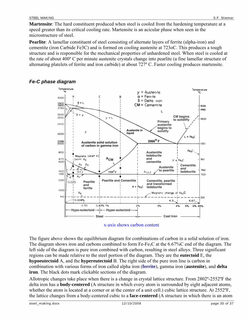
Fe-C phase diagram
x-axis shows carbon content
The figure above shows the equilibrium diagram for combinations of carbon in a solid solution of iron. The diagram shows iron and carbons combined to form Fe-Fe3C at the 6.67%C end of the diagram. The left side of the diagram is pure iron combined with carbon, resulting in steel alloys. Three significant regions can be made relative to the steel portion of the diagram. They are the eutectoid E, the hypoeutectoid A, and the hypereutectoid B. The right side of the pure iron line is carbon in combination with various forms of iron called alpha iron (ferrite), gamma iron (austenite), and delta iron. The black dots mark clickable sections of the diagram.
Allotropic changes take place when there is a change in crystal lattice structure. From 2802º-2552ºF the delta iron has a body-centered (A structure in which every atom is surrounded by eight adjacent atoms, whether the atom is located at a corner or at the center of a unit cell.) cubic lattice structure. At 2552ºF, the lattice changes from a body-centered cubic to a face-centered (A structure in which there is an atom

STEEL MAKING S.F. Stiemer
steel_making.docx 12/10/2009 page 31 of 37
at the corner of each unit cell and one in the center of each face, but no atom in the center of the cube. ) cubic lattice type. At 1400ºF, the curve shows a plateau but this does not signify an allotropic change. It is called the Curie temperature, where the metal changes its magnetic properties.
Two very important phase changes take place at 0.83%C and at 4.3% C. At 0.83%C, the transformation is eutectoid, called pearlite.
gamma (austenite) --> alpha + Fe3C (cementite)
At 4.3% C and 2066ºF, the transformation is eutectic, called ledeburite.
L(liquid) --> gamma (austenite) + Fe3C (cementite)
Toughness The toughness of steel is often measured by a Charpy impact test as the energy absorbed at a given temperature. Depending on the application a different specification of energy level required at a given temperature will be made by the customer, for example for some plate steels to be used in bridges 27 J (equivalent to 20 ft.lb.) at -40 °C is required. A ductile-brittle transition curve can also be determined.
For high performance steels, e.g. aircraft undercarriages, a KIc value may be used to quantify the toughness.
The main contributions to the toughness of steel come from:
Grain size Microstructure Composition
All of these aspects need to be taken into account when selecting or designing a steel for a given application.
There can be confusion over what is meant by hardenability and hardness.
Hardenability
a steel property which describes the depth to which the steel may be hardened during quenching. It is important to note that hardenability is a material property, dependent on chemical composition and grain size, but independent of the quenchant or quenching system (cooling rate). However, the structures obtained across a quenched section are a function of both hardenability and the quenching process (severity of quench).
Hardness
a measure of the resistance of a material to plastic deformation. This depends on the carbon content and microstructure of the steel. Hence the same steel can exhibit different hardness values depending upon its microstructure, which itself may depend on how the sample was quenched, etc.
In order to select an appropriate heat treatable engineering steel for a given application it is important to be able to measure its hardenability. The most convenient way to do this is via Jominy Hardenability (or End Quench) Test. The other technique is to use transformation diagrams but these are more time consuming to generate. However there are now many in the literature that can be referred to.
Effect of grain size The effect of grain size on yield strength, y, is given by the Hall Petch equation for structural steels:
where

STEEL MAKING S.F. Stiemer
steel_making.docx 12/10/2009 page 32 of 37
o is the lattice resistance, i.e. friction stress which opposes dislocation motion, k is a constant, sometimes called the dislocation locking term, d is the ferrite grain size.
Effect of microstructure The microstructure of steel has a significant effect on the strength of steel. For steel with a certain composition the microstructure can be altered through varying the processing route used. For example for strip steels the coiling temperature can be controlled to give varying microstructures in the final coil with varying properties. Review hot rolling of strip steels for more information.
Changing the amount of second phase in a predominantly ferritic microstructure has a pronounced effect on the strength of the steel. This microstructural change can be achieved through control of composition and processing as mentioned earlier. For structural steels produced as plate and sections with a ferrite + pearlite microstructure relatively small changes in the amount of pearlite and ferrite at low levels (~5-10%) have a relatively small effect on the strength level, especially the yield strength as the surrounding ferrite yields first anyway.
Effect of solid solution strengthening The graph below shows how different alloying additions affect the yield strength of a ferrite + pearlite structural steel.
Effect of precipitates Most precipitates in steels are relatively large (compared to GP zones in Al-Cu alloys for example) and strong so dislocations have to travel between them rather than cut through them. This is called Orowan bowing. The effectiveness of the precipitates in the steel depends on their composition (as this controls their thermodynamic stability), size, volume fraction and distribution.

STEEL MAKING S.F. Stiemer
steel_making.docx 12/10/2009 page 33 of 37
Control of the precipitate type, size and distribution can be achieved in plate products using controlled reheating, rolling and cooling schedules and careful alloying additions. The typical alloying additions that are used to generate precipitate strengthening are Ti, V, Nb and Al. These additions can be made individually but more commonly are made in combination depending on the requirements of strength, toughness etc. from the customer. The reason that these additions are used is that their precipitates (carbides and nitrides) have high thermodynamic stability at elevated temperatures which means they also give rise to grain refinement during processing in addition to strengthening at room temperature.
Effect of dislocations The presence of dislocation networks produced through work hardening can result in very high levels of strength, however, it reduces toughness and ductility so is used only for certain steel products. Work hardening is not used to any extent in plate and section steel products but is used in some strip and engineering steel products. For example:
Strip products
Some strip grades that do not require a high level of formability but an increased strength level are supplied with a degree of work hardening. This work hardening is achieved through controlled cold rolling passes after any annealing process (annealing removes the dislocation structure by recovery or recrystallisation). The level of work hardening introduced is determined by the strain during the cold roll passes (i.e. the thickness reduction per pass) and controlled to give the strength levels required. Work hardening, and hence strengthening, can also occur during fabrication, for example during press forming, bending, drawing etc.
High carbon steel products
For example steel wire is often supplied in a work hardened condition as the dislocation networks provide much of the strengthening. High strength steel wire is used in suspension cables, tyre cords, pre-stressed wire and wires can have a yield strength up to 5000 MPa (lower strength values are usually seen for the applications mentioned). The wire is cold drawn from hot rolled to 90% reduction which produces a heavily worked structure.
Transformation diagrams (CCT & TTT) There are two main types of transformation diagram that are helpful in selecting the optimum steel and processing route to achieve a given set of properties. These are time-temperature transformation (TTT) and continuous cooling transformation (CCT) diagrams. CCT diagrams are generally more appropriate for engineering applications as components are cooled (air cooled, furnace cooled, quenched etc.) from a processing temperature as this is more economic than transferring to a separate furnace for an isothermal treatment.
Time-temperature transformation (TTT) diagrams
measure the rate of transformation at a constant temperature. In other words a sample is austenitised and then cooled rapidly to a lower temperature and held at that temperature whilst the rate of transformation is measured, for example by dilatometry. Obviously a large number of experiments is required to build up a complete TTT diagram.
Continuous cooling transformation (CCT) diagrams

STEEL MAKING S.F. Stiemer
steel_making.docx 12/10/2009 page 34 of 37
measure the extent of transformation as a function of time for a continuously decreasing temperature. In other words a sample is austenitised and then cooled at a predetermined rate and the degree of transformation is measured, for example by dilatometry. Obviously a large number of experiments is required to build up a complete CCT diagram.
Given below is a typical TTT diagram:
CCT diagram for a 0.4% C, 1.5% Mn, 0.5% Mo steel:
As you might expect there is a significant influence of composition on the TTT and CCT diagrams. You can review the influence of composition (and grain size) on hardenability by reading through the section on Jominy Quench Tests. For the Jominy Quench Test samples we saw the effect by the change in shape of the hardness curves for the transformation diagrams we see the effect through a shift in the transformation curves. For example:
An increase in carbon content shifts the CCT and TTT curves to the right (this corresponds to an increase in hardenability as it increases the ease of forming martensite - i.e. the cooling rate required to attain martensite is less severe).
An increase in carbon content decreases the martensite start temperature.
An increase in Mo content shifts the CCT and TTT curves to the right and also separates the ferrite + pearlite region from the bainite region making the attainment of a bainitic structure more controllable.
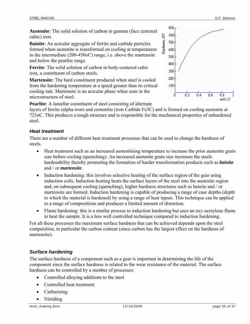
STEEL MAKING S.F. Stiemer
steel_making.docx 12/10/2009 page 35 of 37
Austenite: The solid solution of carbon in gamma (face centered cubic) iron.
Bainite: An acicular aggregate of ferrite and carbide particles formed when austenite is transformed on cooling at temperatures in the intermediate (200-450oC) range, i.e. above the martensite and below the pearlite range.
Ferrite: The solid solution of carbon in body-centered cubic iron, a constituent of carbon steels.
Martensite: The hard constituent produced when steel is cooled from the hardening temperature at a speed greater than its critical cooling rate. Martensite is an acicular phase when seen in the microstructure of steel.
Pearlite: A lamellar constituent of steel consisting of alternate layers of ferrite (alpha-iron) and cementite (iron Carbide Fe3C) and is formed on cooling austenite at 723oC. This produces a tough structure and is responsible for the mechanical properties of unhardened steel.
Heat treatment There are a number of different heat treatment processes that can be used to change the hardness of steels.
Heat treatment such as an increased austenitising temperature to increase the prior austenite grain size before cooling (quenching). An increased austenite grain size increases the steels hardenability thereby promoting the formation of harder transformation products such as bainite and / or martensite.
Induction hardening: this involves selective heating of the surface region of the gear using induction coils. Induction heating heats the surface layers of the steel into the austenite region and, on subsequent cooling (quenching), higher hardness structures such as bainite and / or martensite are formed. Induction hardening is capable of producing a range of case depths (depth to which the material is hardened) by using a range of heat inputs. This technique can be applied to a range of compositions and produces a limited amount of distortion.
Flame hardening: this is a similar process to induction hardening but uses an oxy-acetylene flame to heat the sample. It is a less well controlled technique compared to induction hardening.
For all these processes the maximum surface hardness that can be achieved depends upon the steel composition, in particular the carbon content (since carbon has the largest effect on the hardness of martensite).
Surface hardening The surface hardness of a component such as a gear is important in determining the life of the component since the surface hardness is related to the wear resistance of the material. The surface hardness can be controlled by a number of processes:
Controlled alloying additions to the steel
Controlled heat treatment
Carburising
Nitriding
STEEL MAKING S.F. Stiemer
steel_making.docx 12/10/2009 page 36 of 37
Carbo-nitriding
Controlled alloying additions to steel Alloying elements can be used to control the bulk microstructure of a steel and hence its hardness. For example increasing the carbon content can have several influences on the material hardness:
increases the volume fraction of pearlite in a ferrite and pearlite steel thereby increasing the hardness since pearlite is a harder phase than ferrite.
increases the hardenability of the steel thus promoting the formation of harder transformation products such as bainite and/or martensite.
The influence of alloying elements can be reviewed in the section on the Jominy Hardenability Test.
Carburising Carburising involves the diffusion of carbon into the surface layers of a low carbon steel at high temperatures. Controlled cooling after carburising (water, oil or polymer quenching) produces hard martensitic layers at the surface (this is due to the increased hardenability of the carbon enriched surface region).
Nitriding Nitriding involves the diffusion of nitrogen into the surface layers of a low carbon steel at elevated temperature. The formation of nitrides in the nitrided layer provides the increased hardness. Nitriding is typically carried out in the temperature range of 500 - 575°C, this is in the ferritic state rather than the austenitic used for carburising. This is possible since ferrite has a much higher solubility for nitrogen than it does for carbon.
The advantage of nitriding in the ferritic state is that any previous heat treatment of the steel component is not disrupted and there is little / no distortion of the final component shape. This means that higher carbon steels that have been previously heat treated, such as through hardened steels which have been quenched and tempered, can be surface hardened by nitriding. Nitriding can be carried out using solid, liquid or gaseous media but the most common is gas nitriding using ammonia (NH3) gas as the nitrogen carrying species. To get a hardening effect on nitriding the steel must contain strong nitride forming elements such as Al, Cr and / or V.
Carbo-nitriding Carbo-nitriding is a variation of carburising where both carbon and nitrogen bearing species are used in the gaseous state, usually the inclusion of ammonia in with the carburising gas mixture. Carbo-nitriding is carried out in the austenite state, i.e. temperatures above 850°C, typically 870°C. The case depths are typically lower than those achieved by carburising alone however the surface hardness levels can be higher.
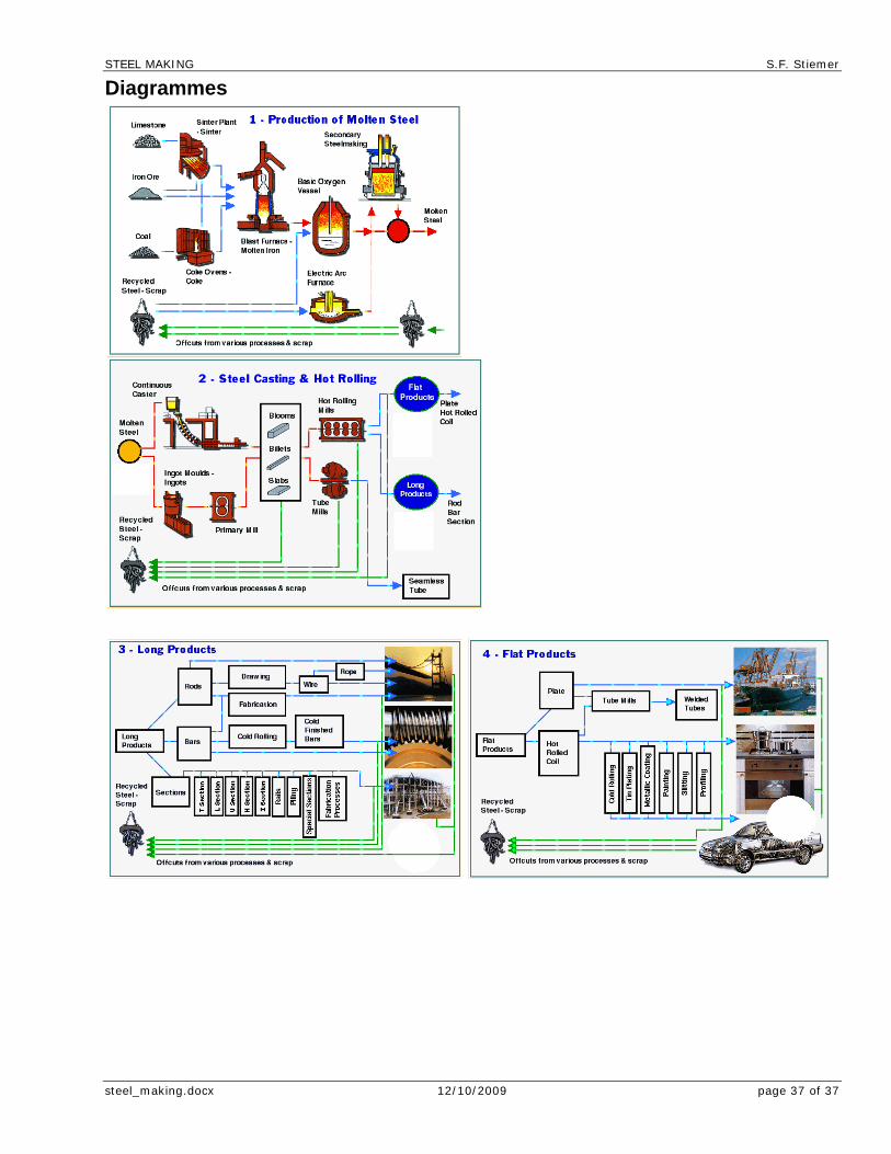
STEEL MAKING S.F. Stiemer
steel_making.docx 12/10/2009 page 37 of 37
Diagrammes