Steel – Glass Roof Skylight and Glass Cable- Net Facades...
19
Project TPQ Office China Steel – Glass Roof Skylight and Glass Cable- Net Facades - preliminary ideas - Prepared For KPF Aman Krishan, Associate Principal New York City USA Prepared By Dennis Poon, PE Managing Principal Will Laufs, PhD LEED AP Vice President Specialty Engineering Thornton Tomasetti Inc. 51 Madison Avenue New York, NY 10010-1603 Phone: 917.661.7800 Fax: 917.661.7801 October 24, 2008
Transcript of Steel – Glass Roof Skylight and Glass Cable- Net Facades...
Project
TPQ Office China Steel – Glass Roof Skylight and Glass Cable- Net Facades - preliminary ideas -
Prepared For
KPF
Aman Krishan, Associate Principal
New York City
USA
Prepared By
Dennis Poon, PE
Managing Principal
Will Laufs, PhD LEED AP
Vice President Specialty Engineering
Thornton Tomasetti Inc.
51 Madison Avenue
New York, NY 10010-1603
Phone: 917.661.7800
Fax: 917.661.7801
October 24, 2008
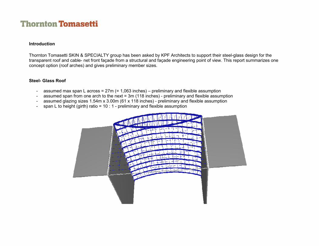
Introduction
Thornton Tomasetti SKIN & SPECIALTY group has been asked by KPF Architects to support their steel-glass design for the transparent roof and cable- net front façade from a structural and façade engineering point of view. This report summarizes one concept option (roof arches) and gives preliminary member sizes. Steel- Glass Roof - assumed max span L across = 27m (= 1,063 inches) – preliminary and flexible assumption - assumed span from one arch to the next = 3m (118 inches) - preliminary and flexible assumption - assumed glazing sizes 1.54m x 3.00m (61 x 118 inches) - preliminary and flexible assumption - span L to height (girth) ratio = 10 : 1 - preliminary and flexible assumption


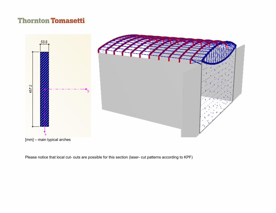
[mm] – main typical arches Please notice that local cut- outs are possible for this section (laser- cut patterns according to KPF)

[mm] – roof purlins

[mm] Main front truss, top and bottom chord - note that the wall thicknesses are preliminary at this stage
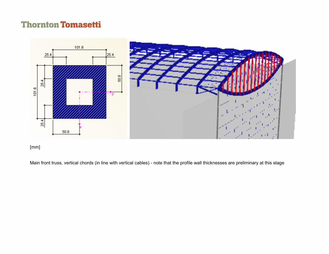
[mm] Main front truss, vertical chords (in line with vertical cables) - note that the profile wall thicknesses are preliminary at this stage

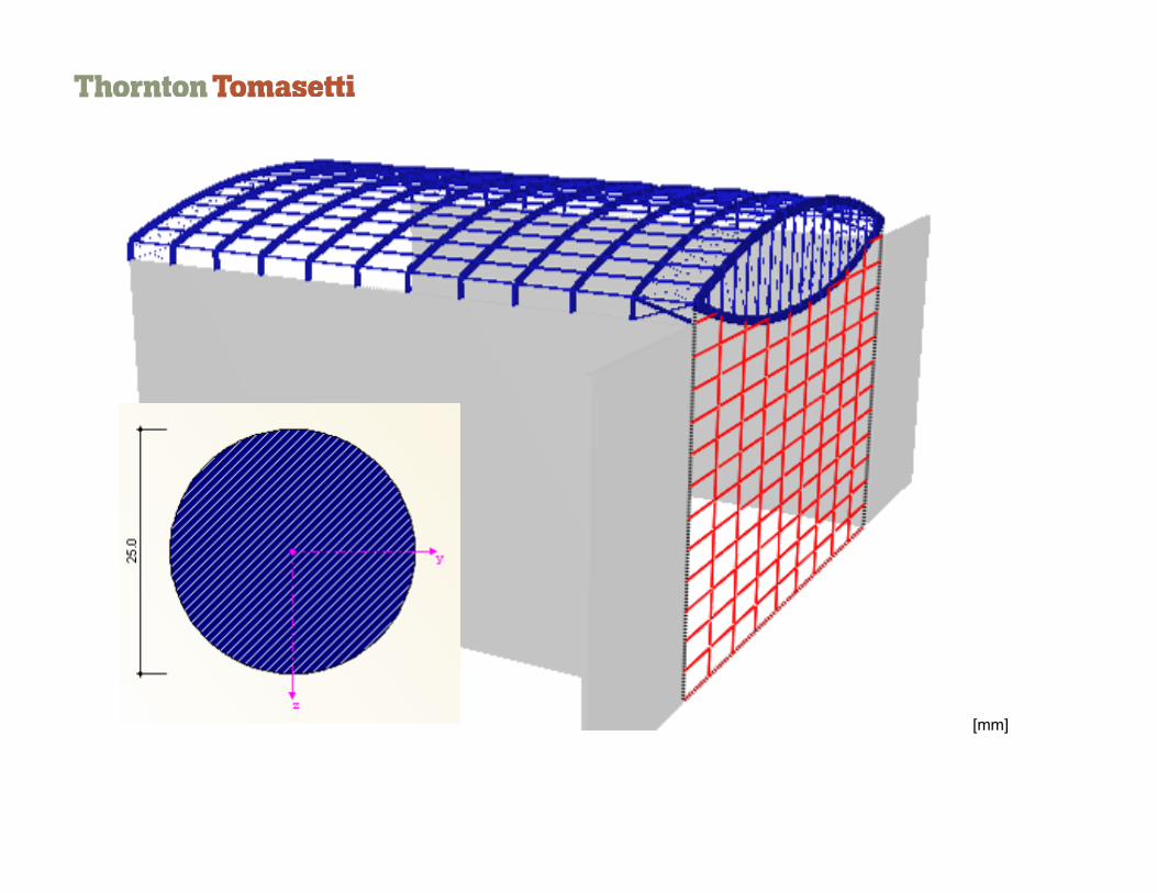
[mm] Main front truss, diagonal cables - note that the cable thicknesses are preliminary at this stage
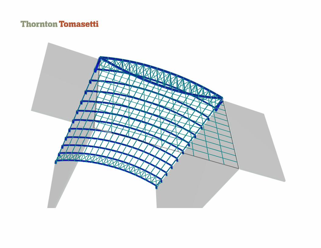
Roof bracing diagonals
[mm]
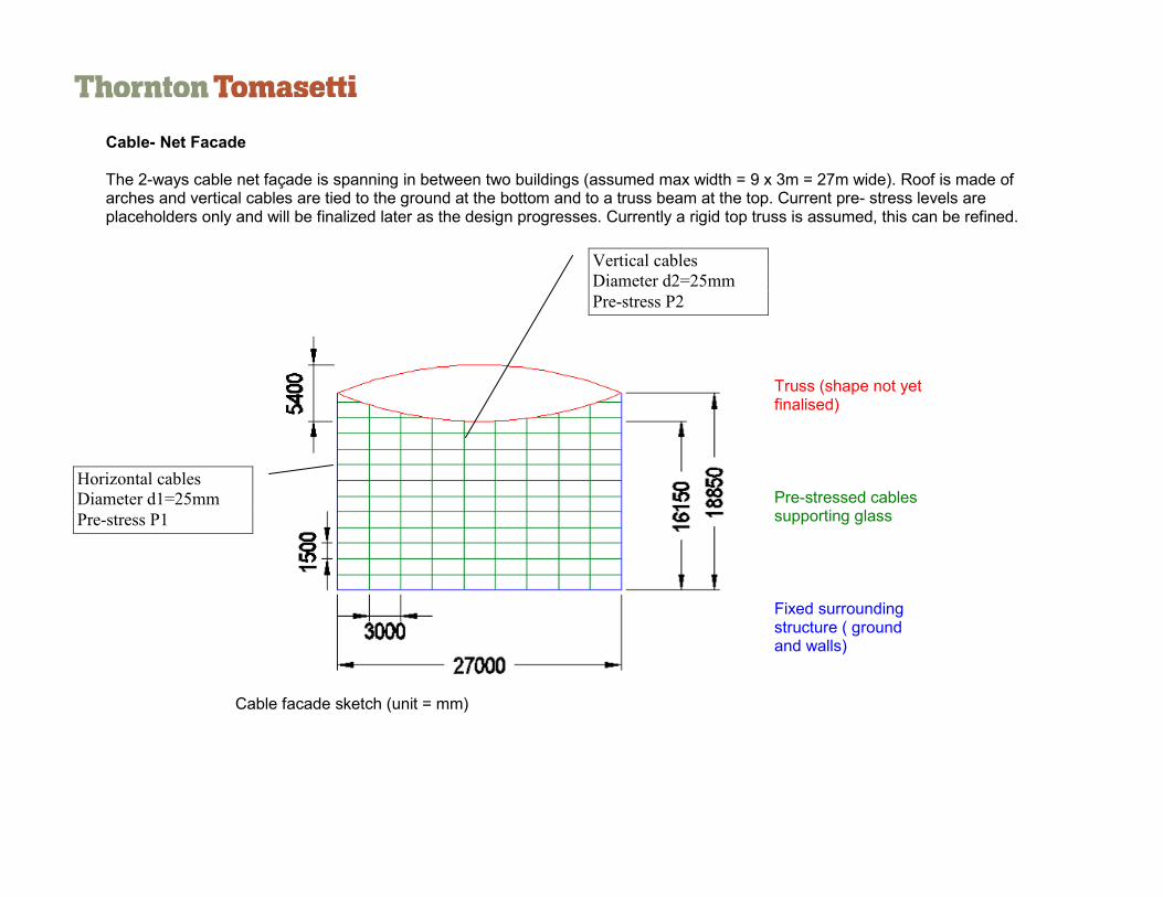
Cable- Net Facade The 2-ways cable net façade is spanning in between two buildings (assumed max width = 9 x 3m = 27m wide). Roof is made of arches and vertical cables are tied to the ground at the bottom and to a truss beam at the top. Current pre- stress levels are placeholders only and will be finalized later as the design progresses. Currently a rigid top truss is assumed, this can be refined.
Truss (shape not yet finalised) Pre-stressed cables supporting glass Fixed surrounding structure ( ground and walls)
Cable facade sketch (unit = mm)
Horizontal cables
Diameter d1=25mm
Pre-stress P1
Vertical cables
Diameter d2=25mm
Pre-stress P2

Forces under pre-stress and max. wind load

Maximum deflection is f max=0.47m=h/34 – careful local glazing fitting and edge support detailed design is required.
Figure 1 Deflections under pre-stress and wind load (40psf)
P0
P1 P2 P3
Deflection f (mm)
470 100 165 69
Angle alpha (/vertical)
3.8° 6.3° 3.1°
Angle beta (/horizontal)
1.9° 1.3°
P1 P2
P3
P0
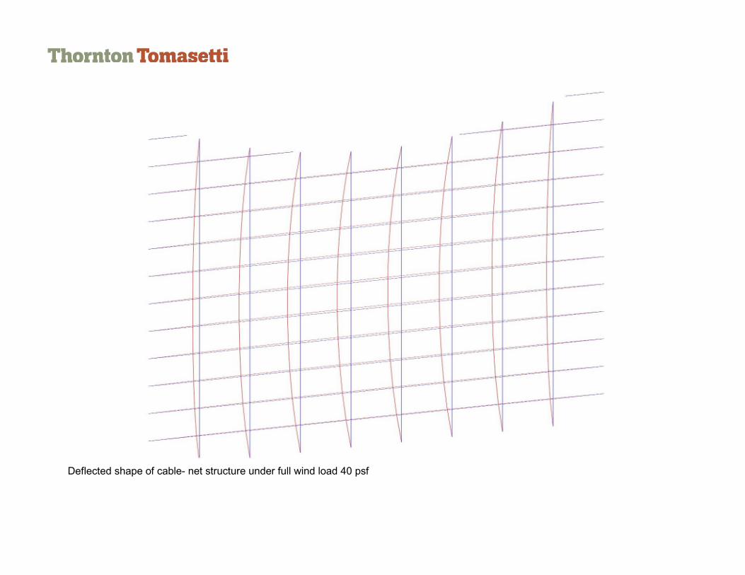
Deflected shape of cable- net structure under full wind load 40 psf

Deflected shape of cable- net structure under full wind load 40 psf

Roof Glazing
- Ceramic frit pattern according to kpf - walk- on glass (with integrated latch-way support points) - IGU with soft solar coating - top lite fully tempered HST / air cavity / bottom lites laminated safety glass composed of heat- strengthened glass
max deflections – ok max stresses - ok
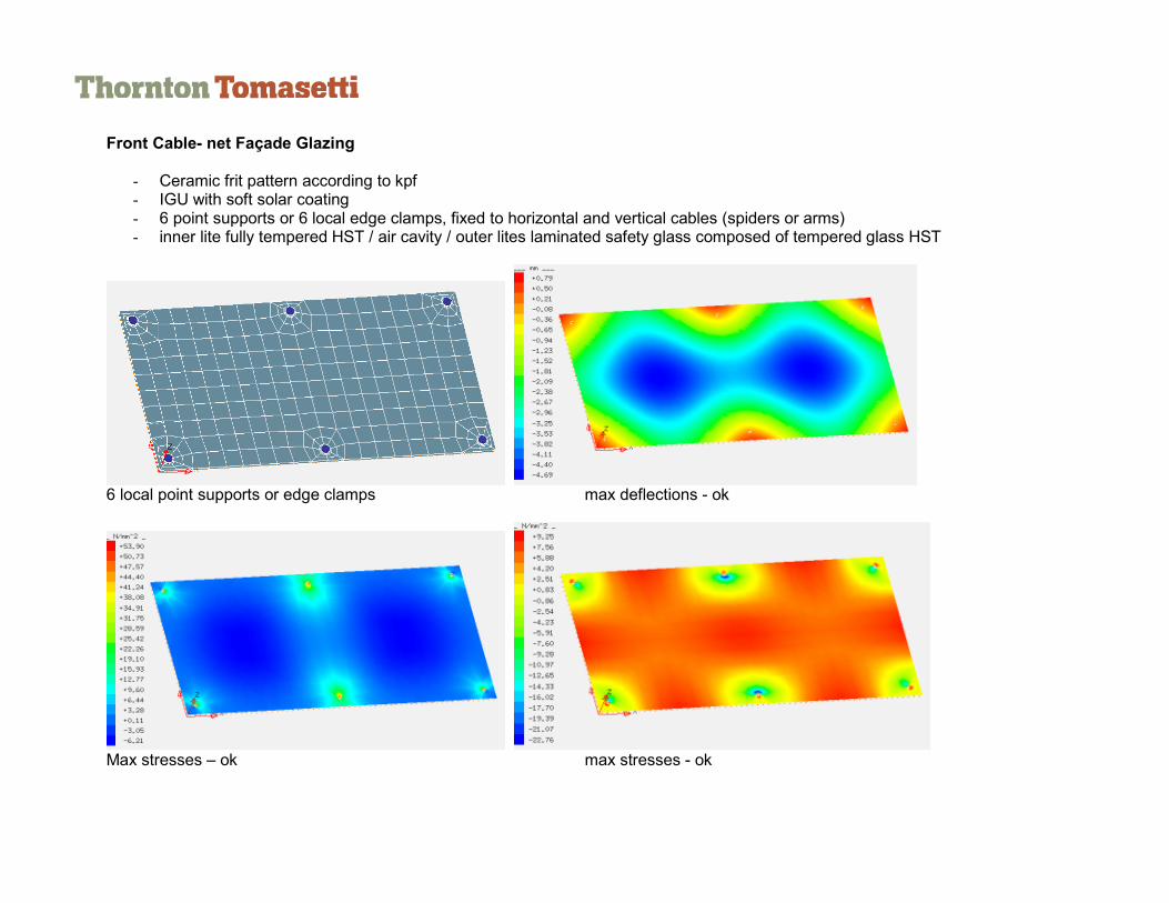
Front Cable- net Façade Glazing
- Ceramic frit pattern according to kpf - IGU with soft solar coating - 6 point supports or 6 local edge clamps, fixed to horizontal and vertical cables (spiders or arms) - inner lite fully tempered HST / air cavity / outer lites laminated safety glass composed of tempered glass HST
6 local point supports or edge clamps max deflections - ok
Max stresses – ok max stresses - ok