Stealth Amplifier Series - Soundstream Stealth Series Amplifier… · l DOUBLE SIDE PCB AND SMD...
20
Stealth Amplifier Series Owner’s Manual
Transcript of Stealth Amplifier Series - Soundstream Stealth Series Amplifier… · l DOUBLE SIDE PCB AND SMD...

Stealth Amplifier Series
Owner’s Manual
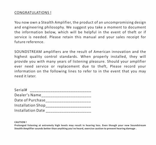
CONGRATULATIONS !
You now own a Stealth Amplifier, the product of an uncompromising design and engineering philosophy. We suggest you take a moment to document the information below, which will be helpful in the event of theft or if service is needed. Please retain this manual and your sales receipt for future reference.
SOUNDSTREAM amplifiers are the result of American innovation and the highest quality control standards. When properly installed, they will provide you with many years of listening pleasure. Should your amplifier ever need service or replacement due to theft, Please record your information on the following lines to refer to in the event that you may need it later.
Serial# ___________________________Dealer's Name______________________Date of Purchase____________________Installation Shop____________________Installation Date ____________________
CAUTION !Prolonged listening at extremely high levels may result in hearing loss. Even though your new Soundstream Stealth Amplifier sounds better than anything you've heard, exercise caution to prevent hearing damage .

FEATURES
l STACKABLE INSTALLATION.l COMPACT SIZE AND TINY FOOTPRINT.l DOUBLE SIDE PCB AND SMD COMPONENTS.l FULL MOSFET DESIGN.l LPF AND SUBSONIC CROSSOVER.l ADJUSTABLE BASSBOOST FREQUENCY AND LEVEL.l INFINITELY VARIABLE PHASE CONTROL FOR MONO MODEL.l ACTIVE X-OVER FUNCTION.l HEAVY-DUTY ALUMINUM ALLOY HEATSINK.l HIGH (Speaker) OR LOW (RCA) LEVEL INPUTS.l OVERLOAD, OVERHEAT, HIGH/LOW VOLTAGE PROTECTION.l RoHS COMPLIANT.
FE
AT
UR
ES
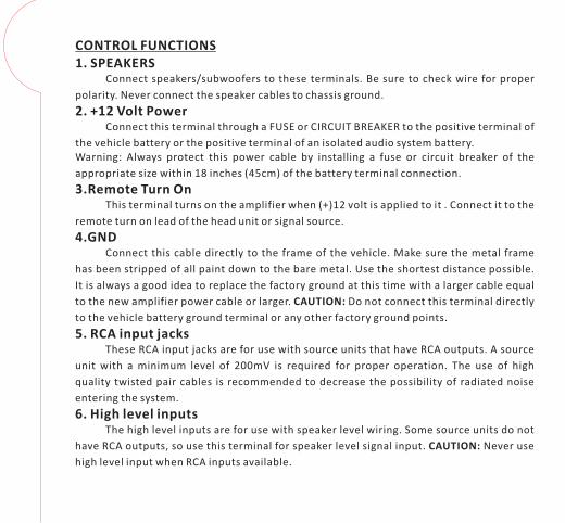
CONTROL FUNCTIONS1. SPEAKERS
Connect speakers/subwoofers to these terminals. Be sure to check wire for proper
polarity. Never connect the speaker cables to chassis ground.
2. +12 Volt PowerConnect this terminal through a FUSE or CIRCUIT BREAKER to the positive terminal of
the vehicle battery or the positive terminal of an isolated audio system battery.Warning: Always protect this power cable by installing a fuse or circuit breaker of the
appropriate size within 18 inches (45cm) of the battery terminal connection.
3.Remote Turn OnThis terminal turns on the amplifier when (+)12 volt is applied to it . Connect it to the
remote turn on lead of the head unit or signal source.
4.GNDConnect this cable directly to the frame of the vehicle. Make sure the metal frame
has been stripped of all paint down to the bare metal. Use the shortest distance possible.
It is always a good idea to replace the factory ground at this time with a larger cable equal
to the new amplifier power cable or larger. CAUTION: Do not connect this terminal directly
to the vehicle battery ground terminal or any other factory ground points.
5. RCA input jacksThese RCA input jacks are for use with source units that have RCA outputs. A source
unit with a minimum level of 200mV is required for proper operation. The use of high
quality twisted pair cables is recommended to decrease the possibility of radiated noise
entering the system.
6. High level inputsThe high level inputs are for use with speaker level wiring. Some source units do not
have RCA outputs, so use this terminal for speaker level signal input. CAUTION: Never use
high level input when RCA inputs available.

CONTROL FUNCTIONS7. REMOTE
Connect the remote controller to control the subwoofer amplifier volume from the driver seat location, for ease of adjustment during playing.
8. LEVEL ControlThe level control will match the amplifiers sensitivity to the source units signal
voltage. The Operating range is 200mV minimum to 5V maximum. This is NOT a volume control!
9. Low Pass Filter Control (Mono)This control is used to select the desired low pass x-over frequency. The frequency
can be adjusted from 40Hz to 220Hz for all bass mono models.
10. Subsonic Filter ControlThis control can filter out unwanted low frequency from 10Hz (OFF) to 50Hz. This
function will increase the power handling of your woofers.
11. Bass Boost Frequency and Level Control (Mono and 2-ch)By adjusting these two knobs, you can boost a wanted frequency to a wanted level.
The center boost frequency is adjustable from 30Hz to 90Hz, the boost level is adjustable from 0dB to 12dB.
12. Phase ControlThis control can adjust speaker output phase from 0 to 180 degrees infinitely to
match your system phase characteristics.
13. X-over mode and frequency Control (4-ch)These controls allow control over the frequencies played for the front channels.
There is an option for Low Pass, Full Range or High Pass. In LP or HP mode the frequency range is from 50Hz to 4kHz.
CO
NT
RO
LF
UN
CT
ION
S

CONTROL FUNCTIONS14. X-over mode and frequency Control (4-ch)
These controls allow control over the frequencies played for the rear channels.
There is an option for Low/BandPass, Full Range or High Pass. In HP mode, the frequency
range is from 15Hz to 500Hz. In LP mode, the frequency range can be switched from 50Hz
to 800Hz, or 250Hz to 4kHz. In the higher range, the LPF can be set at 4kHz for a midbass
while the front channels are also set at 4kHz for a tweeter resulting in a 2-way xover and
eliminating the need for a passive xover. Even with a set up like this, the midbass can still
be protected by the HPF which is not defeatable. It can be set anywhere in the 15Hz to
500Hz range creating a bandpass filter for the midbass by eliminating any damaging lower
frequencies in the subbass region.
15. Bass Boost Level switch (4-ch)This switch can boost bass level by 0dB, 6dB or 12dB. The boost frequency is
centered at 50Hz.
16. Input mode switch (4-ch)This function is for switching the rear channels' signal path. When switched to 4CH,
all 4 RCAs inputs are required. When switched to 2CH, the rear channels get their signal
input from the front channels in parallel.
17. X-over mode and frequency Control (2-ch)These controls allow control over the frequencies played for STL2.350 & STL2.560.
There is an option for Low Pass, Full Range or High Pass. In LP mode the frequency range is
from 50Hz to 200Hz, In HP mode the frequency range is from 15Hz to 200Hz.
18. Power IndicatorThis LED will light up when amplifier works properly.
19. Protection IndicatorThe red LED will light up and will be flashing if there is a fault presented to the
amplifier. Please disconnect the amplifier and resolve the fault before reconnecting the
amplifier.
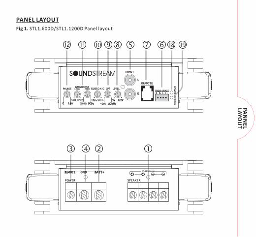
PANEL LAYOUT
123 4
5 68 79 18101112 19
Fig 1. STL1.600D/STL1.1200D Panel layout
PA
NN
EL
LAY
OU
T
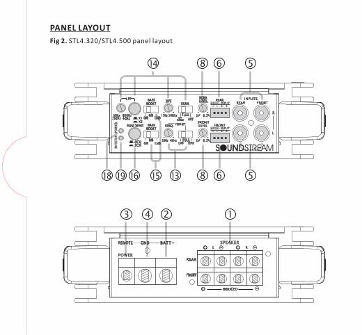
PANEL LAYOUT
Fig 2. STL4.320/STL4.500 panel layout
123 4
568
13 568
14
15161918

PANEL LAYOUT
Fig 3. STL2.350/STL2.560 panel layout
123 4
568111819 17
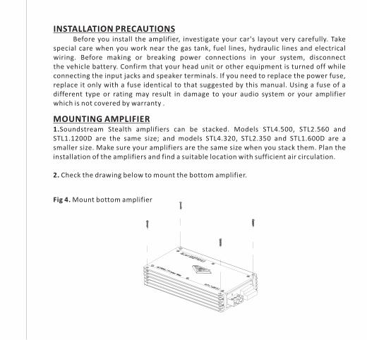
INSTALLATION PRECAUTIONSBefore you install the amplifier, investigate your car's layout very carefully. Take
special care when you work near the gas tank, fuel lines, hydraulic lines and electrical wiring. Before making or breaking power connections in your system, disconnect the vehicle battery. Confirm that your head unit or other equipment is turned off while connecting the input jacks and speaker terminals. If you need to replace the power fuse, replace it only with a fuse identical to that suggested by this manual. Using a fuse of a different type or rating may result in damage to your audio system or your amplifier which is not covered by warranty .
MOUNTING AMPLIFIER1.Soundstream Stealth amplifiers can be stacked. Models STL4.500, STL2.560 and STL1.1200D are the same size; and models STL4.320, STL2.350 and STL1.600D are a smaller size. Make sure your amplifiers are the same size when you stack them. Plan the installation of the amplifiers and find a suitable location with sufficient air circulation.
2. Check the drawing below to mount the bottom amplifier.
Fig 4. Mount bottom amplifier
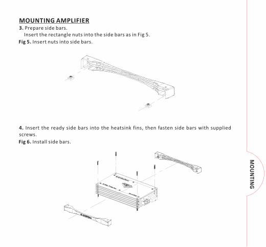
MOUNTING AMPLIFIER3. Prepare side bars. Insert the rectangle nuts into the side bars as in Fig 5.
4. Insert the ready side bars into the heatsink fins, then fasten side bars with supplied screws.
Fig 5. Insert nuts into side bars.
Fig 6. Install side bars.
MO
UN
TING
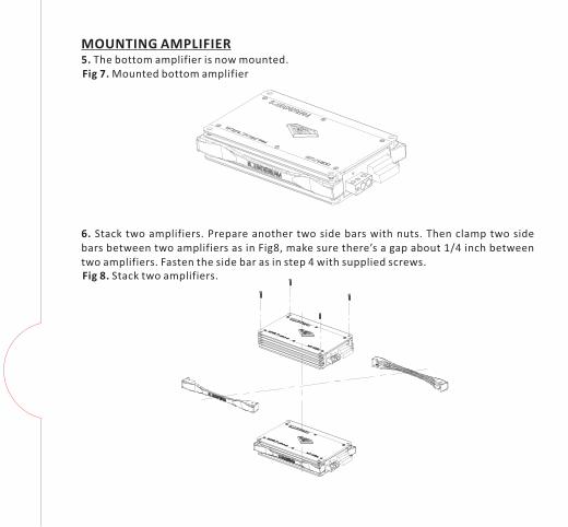
MOUNTING AMPLIFIER5. The bottom amplifier is now mounted.
6. Stack two amplifiers. Prepare another two side bars with nuts. Then clamp two side bars between two amplifiers as in Fig8, make sure there’s a gap about 1/4 inch between two amplifiers. Fasten the side bar as in step 4 with supplied screws.
Fig 7. Mounted bottom amplifier
Fig 8. Stack two amplifiers.

MOUNTING AMPLIFIER7. Mount the third pair side bars. After step 6 two amplifiers have already been mounted securely. Now install the third pair side bars on the top amplifier as in step4.
8. Now you have stacked two amplifiers!
Fig 9. Install the third pair side bars.
Fig 10. Stacked amplifiers.

FU
SE
CONNECTING THE AMPLIFIER1. Select cable and fuse according to the following table.
2. Connect the amplifiers ground cable to a close, bare metal part of the frame or chassis. Use a nut and bolt, NOT a screw! The ground cable must be at least the same size as the +12volt cable.
3. Connect the remote terminal to remote output of the head unit using 16 gauge (or heavier) wire.
4. Connect the fuse holder within 18”(45cm) of the car battery, and run the selected cable from this fuse to the amplifier.
5. Connect all the inputs with high-quality cables. Connect Remote Control if necessary.
6. Insert fuse(s) into the battery fuse holder(s).7. If using a subwoofer for 2-CH and 4-CH, bridge the channels by using the Left “+”
and the Right “-“ terminals.
Fig 11. Mono amplifier wiring
Source Unit
WIRING DIAGRAM
(1 woofer load)
RCA signal
REMOTE signal
MODEL STL1.1200D STL1.600D STL4.500 STL4.320 STL2.560 STL2.350
CABLE 4 6-4 6-4 6 6-4 6
FUSE 100A 80A 80A 60A 80A 60A
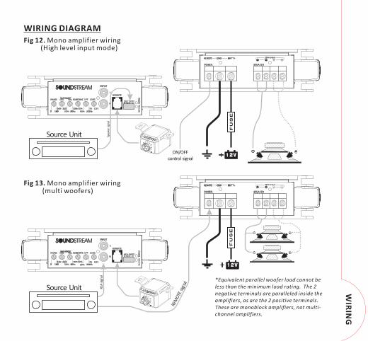
Fig 12. Mono amplifier wiring
WIRING DIAGRAM
(High level input mode)
Fig 13. Mono amplifier wiring(multi woofers)
ON/OFF control signal
Spea
ker
sign
al
*Equivalent parallel woofer load cannot be less than the minimum load rating. The 2 negative terminals are paralleled inside the amplifiers, as are the 2 positive terminals. These are monoblock amplifiers, not multi-channel amplifiers.
FU
SE
Source Unit
FU
SE
Source Unit
REM
OTE
sig
nal
RCA
sig
nal
WIR
ING

4-Ohm to 8-Ohm
Fig 15. STL4.320 / STL4.500 wiring(3-channel mode)
Fig 14. STL4.320 / STL4.500 wiring
WIRING DIAGRAM
(4-channel mode)
Source Unit
CROSSOVER
2-Ohm to 4-Ohm
FU
SE
REMOTE signal
RCA sign
als
CROSSOVER
2-Ohm to 4-Ohm
CROSSOVER
2-Ohm to 4-Ohm
CROSSOVER
2-Ohm to 4-Ohm
Source UnitCROSSOVER
2-Ohm to 4-OhmF
US
E
REMOTE signal
RCA sign
als
CROSSOVER
2-Ohm to 4-Ohm

(High level input mode)
Fig 16. STL4.320 / STL4.500 wiring
WIRING DIAGRAM
(active x-over mode)
Woofer
TweeterSource Unit
FU
SE
REMOTE signal
RCA sign
als
Woofer
Tweeter
Fig 17. STL4.320 / STL4.500 wiring
Source UnitCROSSOVER
2-Ohm to 4-Ohm
FU
SE
CROSSOVER
2-Ohm to 4-Ohm
CROSSOVER
2-Ohm to 4-Ohm
CROSSOVER
2-Ohm to 4-Ohm
Spea
ker s
ignal
ON/OFF control signal
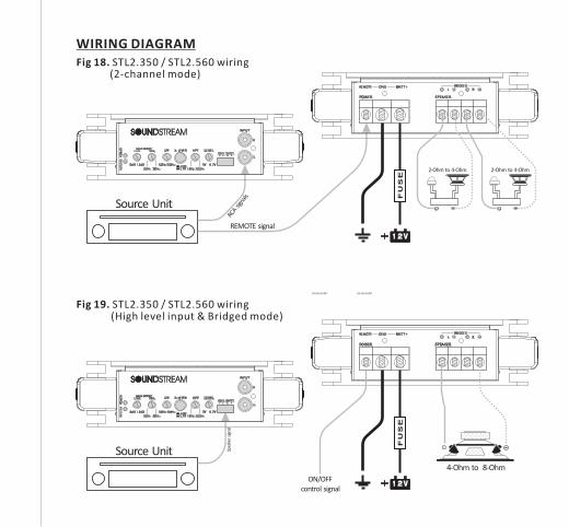
4-Ohm to 8-Ohm
Fig 19. STL2.350 / STL2.560 wiring(High level input & Bridged mode)
Fig 18. STL2.350 / STL2.560 wiring
WIRING DIAGRAM
(2-channel mode)
Source Unit
FU
SE
REMOTE signalRC
A sign
als
CROSSOVER
2-Ohm to 4-Ohm
CROSSOVER
2-Ohm to 4-Ohm
Source Unit
FU
SE
Spea
ker
sign
al
ON/OFF control signal
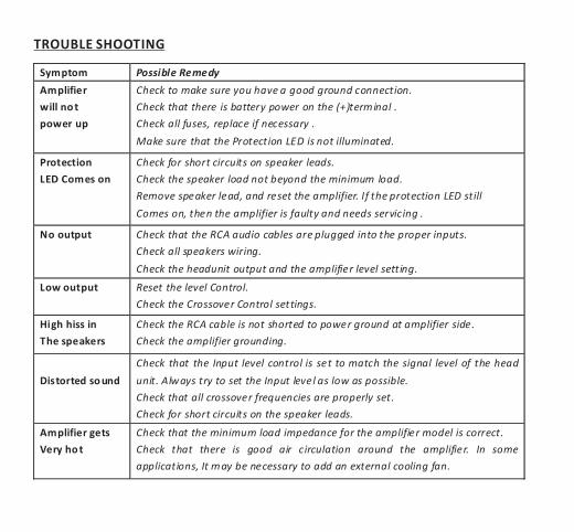
Symptom Possible Remedy
Amplifier
will no t
power up
Check to make sure you have a good ground connection.
Check that there is battery power on the (+)terminal .
Check all fuses, replace if necessary .
Make sure that the Protection LED is not illuminated.
Protection
LED Comes on
Check for short circuits on speaker leads.
Check the speaker load not beyond the minimum load.
Remove speaker lead, and reset the amplifier. If the protection LED still
Comes on, then the amplifier is faulty and needs servicing .
No output Check that the RCA audio cables are plugged into the proper inputs.
Check all speakers wiring.
Check the headunit output and the amplifier level setting.
Low output Reset the level Control.
Check the Crossover Control settings.
High hiss in
The speakers
Check the RCA cable is not shorted to power ground at amplifier side.
Check the amplifier grounding.
Distorted so und
Check that the Input level control is set to match the signal level of the head
unit. Always try to set the Input level as low as possible.
Check that all crossover frequencies are properly set.
Check for short circuits on the speaker leads.
Amplifier gets
Very ho t
Check that the minimum load impedance for the amplifier model is correct.
Check that there is good air circulation around the amplifier. In some
applications, It may be necessary to add an external cooling fan.
TROUBLE SHOOTING

SPECIFICATIONS
Model STL4.320 STL4.500 STL2.350 STL2.560 STL1.600D STL1.1200D
1Ohm Load N/A N/A N/A N/A N/A 1000W
2Ohm Load 75W x 4 120W x 4 160W x 2 230W x 2 300W 650W
4Ohm Load 50W x 4 80W x 4 100W x 2 150W x 2 500W 400W
Input Level
High level input
Frequency Response
X-over Type
LPF
Subsonic / HPF
Bass Boost Frequency
Bass Boost Level
THD
Damping Factor
S/N Ratio
Phase Shift
Minimum Load 2 Ohm 1 Ohm
Voltage Protection
Components & PCB
Bass Remote
Height
Width
Length 245mm / 9.6" 285mm / 11.2" 245mm / 9.6" 285mm / 11.2" 245mm / 9.6" 285mm / 11.2"
0 - 180NA NA
<8.4V & >16V
Yes
2 Ohm 2 Ohm
<8.4V
N/A N/A
>200 >200 >200
>100dB >100dB >85dB
0dB, 6dB, 12dB 0dB - 12dB 0dB - 12dB
<0.05% <0.05% <0.5%
10Hz - 220Hz
LPF/Full/HPF LPF/Full/HPF LPF/Subsonic
15Hz - 25KHz 15Hz - 25KHz
Front 50Hz - 4kHz, Rear 50Hz -
800Hz or 250Hz - 4kHz50Hz - 200Hz 40Hz - 220Hz
SMD Parts / Double-Sided FR-4 PCB
Front 50Hz - 4kHz, Rear 15Hz -
500Hz15Hz - 200Hz 10Hz - 50Hz
50Hz 30Hz - 90Hz 30Hz - 90Hz
RMS power at 14.4V
Features
DIMENSION
<8.4V
0.2~5V 0.2~5V 0.2~5V
Yes Yes Yes
53mm / 2.1" 53mm / 2.1" 53mm / 2.1"
166mm / 6.5" 166mm / 6.5" 166mm / 6.5"


![2016-09-07 R v Ware [2016] ACTSC 264€¦ · Web viewHe then stole a Soundstream subwoofer speaker, silver Soundstream amplifier, a black Phoenix amplifier, ... a Canon PowerShot](https://static.fdocuments.us/doc/165x107/5ea1b3746a89713041337b96/2016-09-07-r-v-ware-2016-actsc-264-web-view-he-then-stole-a-soundstream-subwoofer.jpg)