Centrifugal compressor surge : modeling and identification for control

STEADY STATE COMPRESSOR MODEL AS A BASIS FOR ANTI-SURGE CONTROL ACTION
Daniel Dias Leister Satildeo Paulo University Satildeo Paulo SP Brazil
Song Won Park Satildeo Paulo University Satildeo Paulo SP Brazil
ABSTRACT Dynamic compressors are known to suffer from surge which
can severely damage compressor components and disturb production Surge may arise by the occurrence of disturbances (eg compressor discharge valve closure) that would bring its operating point to a region at low flows delimited by the so called surge line (SL) Therefore dynamic compressors are always equipped with anti-surge mechanisms typically a fast actuating recycle valve controlled by a PI anti-surge controller Since surge develops extremely fast the compressor is usually not allowed to operate too close to the surge line A surge safety margin is considered which is the region between the SL and a surge control line (SCL) which may be defined as a line parallel and to the right of the SL Once the compressor crosses the SCL towards the SL PI controller action starts Depending on a number of factors the recommended surge margin adopted may vary This control objective (keep the compressor away from the SL) is conflicting with energy efficiency requirements since higher efficiency operating points are located close to the SL Therefore it is desirable to operate the compressor using the smallest possible surge margin that still guarantees anti-surge action is effective In this paper we propose a method for triggering the compressor anti-surge action aiming at a faster action than traditional PI control which could enable the adoption of reduced surge margins and operation with higher efficiency Given a typical single compressor system topology the possibility of a compressor reaching the surge region coming from a stable operating point can be retrieved through the state of the system actuators Considering a certain combination of values of the system actuators (compressor suction valve opening discharge valve opening and motor drive torque) if the steady state operating point (calculated based on a nonlinear variable speed compressor system model) lies to the right of the SCL then no anti-surge action is necessary If the resulting steady state lies to the left of the SCL anti-surge action is deemed necessary and therefore triggered The proposed anti-surge control method relies on an offline computation of necessary recycle valve openings for each possible combination of the system actuators positions mentioned above considering a predefined discrete set of values from the actuators positioning ranges This generates a look-up table for online use The values
from the look-up table are used to trigger a ldquosteady state control actionrdquo for the recycle valve that would keep the system stable after transients vanish They are also used to identify the necessary compressor flow set-point for a feedback controller which is responsible for ensuring that the system trajectory goes from the state upon anti-surge activation to the desired steady state The control action from this feedback controller is added to the steady state control action so that its contribution should vanish after transients vanish A PI and a sliding mode controller are used in feedback control action and results are compared to the traditional anti-surge control approach
INTRODUCTION
Surge is an instability that affects dynamic compressors (centrifugal and axial) It can severely damage compressor components and disturb production and may arise by the occurrence of disturbances (eg compressor discharge valve closure) that would bring its operating point to a region at low flows in the compressor map This region is delimited by the so called surge line (SL) Surge may cause severe oscillations in the variables that characterize the compressor system state namely pressures and flows It occurs when the compressor cannot produce sufficient pressure to maintain the flow in such a way that it causes a drop in the compressor flow which in turn drops the outlet pressure [16] This in turn makes the flow increase again and the process repeats itself creating the surge cycles There are different levels of surge severity which in general are undesired being the deep surge the most critical one where even flow reversal through the compressor may occur during the surge cycles [15]
We consider in this paper a typical single compressor system topology as depicted in Figure 1 with a recycle valve as the anti-surge actuator
Here and are the pressures upstream and downstream the compression system respectively and are considered constant The flows are denoted by with a subscript is the torque applied by the electric motor drive to the compressor shaft which has a speed Valve openings are denoted as and the corresponding subscript The following subscripts are
Proceedings of the ASME 2014 International Mechanical Engineering Congress and Exposition IMECE2014
November 14-20 2014 Montreal Quebec Canada
IMECE2014-40348
1 Copyright copy 2014 by ASME
considered for inlet for outlet for recycle for steady state and 13 for compressor
Figure 1 ndash Schematic diagram of a typical compression system
Dynamic compressors are equipped with anti-surge mechanisms whose primary goal is to prevent the compressor operating point to achieve the unstable region (to the left of the SL) Different actuators are used depending on the equipment and application but one of the most common schemes is to install a recycle valve which is responsible for partially reinjecting the compressor output to its inlet as a means of increasing the total compressor flow which would contribute to bring the compressor away from the surge line
Research on compressor anti-surge control systems has been focused on the active anti-surge control strategy (see for a few examples [1-5]) where it is proposed to extend the operational range of the compressor beyond the surge line by the use of a continuous control action the guarantees the dynamic stability of the system is this extended region However as noted in [67] this control philosophy has not yet been applied in industrial grade applications Probably due to the high risk (notably of equipment damage and loss of production) involved in the occurrence of surge and the very fast nature if it industry still relies on strategies based on the surge avoidance strategy where the objective is to prevent the compressor from approaching the surge line typically by the use of a PI controller with some enhancements
This paper proposes an alternative scheme to the traditional anti-surge control approach though still may be classified as a surge avoidance control strategy This is justified by the fact that a great amount of costs associated with the acquisition and operation of industrial compressors accounts for energy costs Thus subtle increments in operational efficiency during the lifecycle of a compressor may give significant savings The main objective is to allow safe operation closer to the SL what typically coincides with greater efficiency curves [8]
Maybe due to its relative conceptual simplicity little academic work can be found on the traditional PI anti-surge control Details of the control algorithms seem to be usually considered as sensitive information by control system suppliers and thus are not usually available However there are some few references clearly directed to practitioners that give relevant information on traditional anti-surge control systems [9-11]
COMPRESSOR SYSTEM MODEL The compressor system topology depicted in Figure 1 is
modeled mainly based on the variable speed centrifugal compressor model of [12] (equations (4) and (10) can be found on the related work of [14]) with six states as follows
∙ (1)
∙ (2)
∙ ∙ (3)
$ampamp(( (4)
1 (5)
$ampamp (6)
The terms that appear in the differential equations above are detailed below
amp ∙ 0| | ∙ 234 (7)
56 76 ∙ 0 8 0 (8)
ampamp ∙ 0| | ∙ 234 (9)
lt=gt A2 ∙ 2C60 || (10)
ampamp(( E F E F
EG FG EH FHG
(11)
We make here some notes regarding this model bull The term ampamp( ( refers to the compressor
characteristic which is typically obtained experimentally and approximated by polynomials as here with a third order polynomial E to EH and Fto FH are constant coefficients
bull Equation (6) has been included to introduce some dynamics to the recycle valve movement and thus account for possible performance degradations due to the inclusion of it (primarily the faster the anti-surge action the better should be the anti-surge control performance)
bull Equations (7) (8) and (9) are typical linear valve equations The difference in equation (8) relates to the presence of the check valve in the system output to prevent backflow
bull The term refers to the resistance that the compressor offers to the torque applied by the electric motor [14]
2 Copyright copy 2014 by ASME
Figure 2 ndash Compressor map with constant torque line
bull The IJK factor is present due to the fact that angular
velocity measurements in the specific model used here are considered in rpm and not rads
Annex A shows additional information regarding the system
model TRADITIONAL ANTI-SURGE PI CONTROL
Figure 2 shows a compressor map with the SL and another line termed Surge Control Line (SCL) Since the objective of surge avoidance control systems is to keep the compressor away from the surge line ie to the right of it the SCL is used as a kind of limit to trigger anti-surge action A PI controller is used to open the recycle valve as the compressor crosses the SCL towards the SL
For that purpose the controlled variable is the compressor flow () The PI controller setpoint is calculated as the compressor flow on the SCL that has the same pressure ratio as the current operating point Note that since is not a measured
variable it is usually estimated by the relation L The controller is configured such that when the error is negative ie the compressor is to the left of the SCL the output is positive saturating at 1 (100 valve opening) when the error is positive the output would be negative but the PI controller has a lower saturation limit at 0 (valve fully closed) Thus no action is taken by controller A PI controller with anti-windup activated is necessary so that this does not have negative impact on the system behavior
The scheme described above is capable of providing basic anti-surge action However if a disturbance hits the system too fast the PI controller alone may not be able to prevent the compressor from crossing the SL For that purpose a derivative-like action must be implemented Traditional derivative action is not generally implemented because of noisy measurements One of the usual workarounds is to estimate the flow variation and
increase the PI setpoint proportionally to this estimate if it is negative that is the compressor is approaching the SL (see for example details in [11]) Figure 3 details the implementation of this scheme
Figure 3 ndash Traditional PI control with flow rate compensation
STEADY STATE MODEL BASED ANTI-SURGE CONTROL
The control strategy proposed in this paper is based on the idea that the current state of the system inputs can be used to predict the steady state operating point of the system By making the derivatives equal to zero in the system model equations we have a nonlinear system of equations shown below whose solutions may correspond to steady state operating points considering the system inputs as constants
0 (1) minus minus = 0 (2)
0 5 10 15 20 251
2
3
4
5
mc (kgs)
p r
Constant speed linesSurge lineSurge Control lineConstant torque lines
3 Copyright copy 2014 by ASME
∙ minus = 0 (3) ampamp(( minus = 0 (4)
minus lt=gt A2 ∙ 2C60 || = 0 (5)
∙ 0| minus | ∙ 234 minus minus = 0 (6) minus amp ∙ 0| minus | ∙ 234 minus = 0 (7) minus 56 = 0 (8)
So the problem of anti-surge control is split into two separate problems
1) Based on the current system inputs state identify the possibility of it entering surge and generate a reference value for the recycle valve opening (M) and a
reference value for the compressor flow (ampN) The
valve reference value refers to the valve opening that would keep the system stable in the steady state considering the inputs states are kept constant And the flow reference value is the corresponding expecteddesired flow at the steady state The component responsible for generating at each controller scan cycle this pair of values is referred to as Reference Generator (RG)
2) Use ampN for regulatory control that manipulates the
recycle valve opening using a feedback control law The output of this controller is incremental to the M
generated by the RG This feedback controller will be referred to simply as Controller
Figure 4 ndash Proposed control scheme
The idea is that since the RG calculates only values related to steady states these values can be precalculated offline For that purpose the possible ranges of each system input states must
be converted to discrete sets of values Then the OampN MP
pairs calculated offline for each possible combination of the system input states (apart from obviously) that is for each combination of the possible discrete values of and
This is achieved using the system model equations and making all derivatives equal to zero as shown in the beginning of this section Since nonlinear systems of equations might not be so simply solved through a set of algebraic manipulations and steps it is possible to come to the desired values for the RG To obtain these values two situations are considered
bull Step A the recycle valve closed (normal operation no anti-surge action needed)
bull Step B the recycle valve is partially or fully open (anti-surge action active)
Beginning with Step A considering all the system equations
in steady state (derivatives equal to zero) and starting with the first case adding up equations (1) and (2) in the steady state we have = amp0 minus = 60 minus amp minus = 6 minus And replacing in equation (3)
= amp + 66 + amp (9)
The only unknown here is and assuming we know its
value we can calculate as above and the remaining variables as follows = (10)
= 60 minus (11)
= (12)
= (13)
Now we need a way to know the value of From equations (1) and (11) we get
E + F + E + F + EG + FG+ EH + FHG minus = 0 (14)
The equation above can be regarded as a third order
polynomial with as the unknown A physically meaningful solution must correspond to a positive real root Initially since it has three roots we will assume that it has only one positive real root This is not justified by any analytical verification in the scope of this work but will be checked during the offline calculations Thus if we assume as known we can write = Using equation (1) and the relationships already developed here we have QRamp + 66 + amp S minus minus mUV = 0 (15)
This is a nonlinear equation in which is unknown We will
solve it numerically starting from an initial guess Finally for the calculation of ωU we can use equation (5)
4 Copyright copy 2014 by ASME
= lt=gt OA2 P ∙ O2C60P || (16)
If no valid solution can be found using Step A then Step B is performed Since the recycle valve is not anymore closed and are also unknown If the anti-surge control is active then the required solution should lie (on the compressor map) on the SCL In Figure 2 we can see that there is always only one point in which a certain torque line and the SCL cross each other Thus for a particular torque value applied to the motor in the steady state the required steady state operating point will be exactly this crossing point Obviously within the continuous range of possible torque values (see annex A) there are infinite possible values but considering a discrete set of those values if the distance between each discrete torque line is sufficiently small these discrete values (and the corresponding lines) can be used together with the SCL to calculate the crossing point for a certain combination of the system inputs state From that we have the values of and of the desired solution
This is obtained as follows rewriting equation (5) (it is assumed here that mU gt 0
= (17)
with = lt=gt OYZ P ∙ OIJKP (18)
Equation (11) may be rewritten as
ampamp[( = E + F + E + F + EG + FG + EH + FH G
(19)
With a constant torque this is the equation for the constant torque lines shown in the compressor map If we write the SCL equation as = = E= + F= (20)
The intersection point of it with the SCL can be found with = = ampamp[(
E= + F= = E + F + E + F + EG + FG + EH + FH G
H EH + G]FH + EG^+ ]FG + minusE= + E^+ ]F + minusF= + E^+ F = 0
(21)
The above equation is a fourth order polynomial with unknown and will be solved in the same way as for the calculation of in Step A With from this equation can be obtained from equation (23) With these two values we can calculate and in the same way as in Step A and m_ can be obtained from equations (7) and (8) and using equations (1) and (9) as follows = minus (22) = 0| minus |234 minus (23)
Thus the algorithm for obtaining the solution of the system that represents an equilibrium point of the system can be written as 1) Step A
a) Calculate with equation (15) b) Calculate with equation (9) c) Calculate with equation (10) d) Calculate with equation (11) e) Calculate and with equations(12) and (13) f) Calculate with equation (16) g) Confirm if the initial hypotheses are valid
i The point is to the right of the SCL ii lt
ii i lt h) If all the hypotheses above are valid for the obtained
solution then the solution is considered valid Otherwise a new solution is calculated using Step B
2) Step B a) Calculate with equation (21) b) Calculate with equation (20) c) Calculate e as in Step A d) Calculate with equation (7) e) Calculate with equation (8) f) Calculate with equation (22) g) Calculate with equation (23) h) Confirm if the following hypotheses are valid
i gt 0 ii lt
ii i gt i) If all the hypotheses above are valid for the obtained
solution then the solution is considered valid Otherwise no valid solution could be obtained
This algorithm is used to calculate the OampN MP pairs
that will be used by the RG This is done offline and once for each possible combination of the system inputs states within the predefined discrete set of possible values When controlling the compressor the RG reads the current value of the system inputs
5 Copyright copy 2014 by ASME
( and ) and gives as output the pair OampN MP which
is calculated through a linear interpolation over the pre-calculated values at the points closest to the current combination of system inputs So the RG is in practice a lookup table combined with a linear interpolation
For the purpose of this work the Controller that receives ampN and outputs the incremental recycle valve opening
(∆M) could be any feedback control algorithm In this work
for a matter of comparison with the traditional PI control we will use a simple PI controller with anti-windup activated (this will be termed here as RG-PI)
Also as detailed in the previous section the RG can calculate reference values not only for ampN and M but also for any
other state variable So we will also implement an alternative scheme with the RG by using the recycle flow () as the measured and controlled variable
In this case however a traditional sliding mode controller (SMC) will be used as detailed below (this will be termed here as RG-SMC) The traditional SMC can be implemented using the equivalent control approach [13] In this approach the control signal is split into two terms a = ab + ∆a
(24)
Where ab term refers to the control signal would make the system to slide exactly over the switching surface once there (s=0) and ∆a is the discontinuous term that is responsible to bring the system to the switching surface and keep the system at it in the presence of disturbances The switching function (s) must be defined and the control objective is to bring the system to the switching surface (s=0) and keep it at this surface In this case we will considerer the error signal as the switching function = = M minus
(25)
Considering a system of the form c = 5c d + 3c da
(26)
Where c is the state vector and 5 and 3 nonlinear functions The equivalent control term can be calculated as follows [13] ab = minus Reec 3c dSf eec 5c d
(27)
In this case a refers to the control signal from the SMC controller (ghi) that is added to the M to form the total control action
= M + ghi
(28)
Applying the equivalent control expression to this case and considering equation (6) we have = ∙ 0| minus | ∙ 234 minus
(29)
Thus ab = ampjghi = minus K ∙ 0| minus | ∙ 234 minus
(30)
With K = ampN ∙ 0| minus | ∙ 234 minus
(31)
The term ∆a can be defined as a saturation function [13] ∆a = k +l gt ∆Fl minus∆F le leminusl lt minus∆F ∆F (32)
Where ∆F is the boundary layer width typically used to prevent chattering in traditional SMC [13] In this case we have modified it to make use of the maximum available actuator range in the following way ∆a =
nopoq 1 minus ab gt ∆F1 minus ab le ∆Fab minus∆F le minusab lt minus∆F (33)
Thus the total control signal for the RG-SMC controller is = M + Obghi + ∆aP
(34)
Note that this approach of using the recycle flow as controlled variable would not be directly applied with the traditional anti-surge control since the reference values for the recycle flow rely on the RG calculations
PROFILE OF THE RG LOOK-UP TABLE RESULTS
For the purpose of generating the RG lookup table the inlet and outlet valve openings have been changed in steps of 1 (001) and the drive torque in steps of 10 Nm Initially the calculations have been done from the torque ranging from 400 to 1200 Nm However according to the criteria presented in the algorithm for obtaining the offline solution for the RG (previous section) some invalid solutions have been obtained below 460 Nm whose reason is still unknown and not further investigated in this paper Therefore only values equal or greater than this limit are considered in the results shown It should also be observed that for none of the valid solutions the assumption for equations (14) and (21) that only one positive real root was available failed
Figure 5 shows the profile of M and M values
obtained for three different torques as a function of and Examining the ampN profiles the regions in which the
compressor may be operated with the recycle valve closed can be easily seen The higher the torque the greater is this region Also necessary recycle valve openings tend to be higher for lower torques It can also be checked that for ampN when the
recycle valve is open there is one single value which is exactly the value found in the intersection between the SCL and the constant torque line for the corresponding torque The remaining values refer to the steady state values when under normal operation This can also be seen on the compressor map Figure 6 shows a plot of the solutions for all the possible input combinations (undersampled to improve visibility) The red dots represent points in which the recycle valve opening is more than
6 Copyright copy 2014 by ASME
Figure 5 ndash Profile of M and M for different torques
Figure 6 ndash Distribution of Reference Generator valid points in compressor map
7 Copyright copy 2014 by ASME
1 thus with the anti-surge considered active and the blue
crosses represent the opposite situation It is worth noting that the points for which it is necessary to
open the recycle valve are overlapped since for the same torque line there are many possible input combinations that generate a point on the SCL with the recycle valve with different openings SIMULATION SCENARIOS
We propose two simulation scenarios in order to evaluate the
feasibility of the proposed scheme and its performance when compared to the traditional PI control scheme
The simulations consider a sudden closure of the inlet (case 1) or outlet (case 2) valves from a given normal operation value down to 20 This disturbance occurs at time t=50s The simulations start with the controller in steady state under normal operation in a point very close to the SCL and high torque (1200Nm)
Figures 7 8 and 9 show the system trajectory in the compressor map for case 1 for the three controllers We can see that for case 1 both PI controllers could prevent the system from entering surge but not from crossing the surge line (for the RG-PI controller the system has even been through one surge cycle) This indicates that either the PI controllers tuning should be more aggressive (what may have adverse effects under other situations) or the SCL should be placed farther from the SL The RG-SMC controller was the only one capable of stabilizing the system without even crossing the surge line The resulting control signals (recycle valve openings) are shown in Figures 10 and 11 It is interesting to see that all three controllers converge to the same stationary control signal
Figure 7 ndash System trajectory for case 1 with traditional PI
control
Figure 8 ndash System trajectory for case 1 with proposed RG-PI
control scheme
Figure 9 ndash System trajectory for case 1 with proposed RG-
SMC control scheme
Figure 10 ndash Control signal for the three controllers in case 1 ndash
full simulation time range
13 135 14 145 15 155 16 165 17
55
56
57
58
59
6
61
62
63
64
mc (kgs)
p r
P1
Final point
-20 -15 -10 -5 0 5 10 15 20 25 30
3
35
4
45
5
55
6
mc (kgs)
p r
P1
Final point
145 15 155 16 165 17 175 18 18554
55
56
57
58
59
6
61
62
63
64
mc (kgs)
p r P1
Final point
8 Copyright copy 2014 by ASME
Figure 11 ndash Control signal the three controllers in case 1 ndash just
after disturbance time range
For case 2 shown in Figures 12 13 and 14 the proposed RG-PI scheme was clearly unable to prevent the compressor from entering surge what the traditional PI control achieves without crossing the SL However the better performance of the RG-SMC controller is again notable since it has not even crossed the surge control line Figures 15 and 16 show the corresponding control signals for the traditional PI and the RG-SMC controllers (RG-PI controller signal has been omitted for clarity)
Figure 12 ndash System trajectory for case 2 with traditional PI
control
Figure 13 ndash System trajectory for case 2 with proposed RG-PI
control scheme
Figure 14 ndash System trajectory for case 2 with proposed RG-
SMC control scheme
Figure 15 ndash Control signal for the traditional PI and the RG-
SMC controllers in case 2 ndash full simulation time range
Figure 16 ndash Control signal for the traditional PI and the RG-SMC controllers in case 2 ndash just after disturbance time range
14 145 15 155 16 165
5
52
54
56
58
6
mc (kgs)
p r
P1
Final point
-20 -15 -10 -5 0 5 10 15 20 25 303
35
4
45
5
55
6
mc (kgs)
p r
P1
Final point
145 15 155 16 165 17 175 18
53
54
55
56
57
58
59
6
61
mc (kgs)
p r
P1
Final point
9 Copyright copy 2014 by ASME
SOME ASPECTS ON THE PRACTICAL IMPLEMENTATION OF THE PROPOSED SCHEME
It is worth making some notes on the practical implementation of the proposed scheme making use of the RG Basically the most demanding part of the algorithm in terms of processing power would relate to the identification of the corresponding entries in the look-up table provided by the RG (verification of currently read values from system inputs to identify the relevant entries in the table) which would require the use of an appropriate search algorithm and the linear interpolation using the entries from this look-up table The feedback controllers considered here should not be as demanding as this first step
From the point of view of the memory usage the look-up table would have to be implemented basically as a 3-dimensional matrix of floating point numbers Considering a 32bit format for a floating point number in the simulations shown here we have a total of 531441 points (number of combinations of 81 discrete values for each input variable) resulting in approximately 2MB of memory what is readily available in high-end industrial controllers
Although we do not wish to make any conclusive affirmation regarding practical implementations in this work the authors do not think processing power and storage memory should be impeditive factors when trying to implement this scheme in high-end controllers CONCLUSIONS
This paper proposes an alternative method for triggering the anti-surge action in dynamic compressors The main proposal refer to the use of steady state model to make offline calculations of reference values for valve openings and the anti-surge controlled variable These are interpolated online to produce information to the anti-surge control which is carried out by a regular feedback controller
The simulations presented here did not show any advantage with the proposed scheme and the PI controller (RG-PI) over the traditional PI control However the approach using the SMC controller (RG-SMC) clearly delivered better results than the traditional approach in the two scenarios considered
The main conclusion that can be drawn from this work is that the use of the RG for anti-surge controller together with a feedback control law has a good potential of becoming a feasible and more efficient approach then the traditional control considering that smaller surge margins could be used allowing the compressor to be operated in greater efficiencies However it should be noted that for a more conclusive analysis different scenarios with several different controller tunings should be tested Also for the RG-SMC control more investigation would be necessary to evaluate the feasibility of a proper recycle flow measurement and what influence it could have on the anti-surge control performance
It should be noted that one of the main probable drawbacks of the proposed scheme which has not been considered in this study is that it relies on some of the system model parameters to generate the reference values calculated offline That is model
uncertainties may make the system generate wrong reference values So in a practical application a sensitivity analysis should be performed and probably an online validation scheme should be used This could be for example a system that compares the reference values generated under normal operation with values measured directly from the system
Also we would like to highlight some possibilities not exploited in the present work
bull Use of other feedback control laws other than the ones mentioned here
bull Since the RG can generate information relative to the normal operation points it may be useful for an integrated load and anti-surge control approach The offline calculations may also be useful for more sophisticated control schemes that for example optimize a certain aspect of the system
ACKNOWLEDGMENTS We would like to thank ABB Corporate Research in
Switzerland for the compressor system model used in this research
REFERENCES [1] Chi JN and Paduano JD 2008 New Concepts for
Active Control of Rotating Stall and Surge in American Control Conference pp 2435-2442
[2] Daroogheh N Jahed-Motlagh MR and Beheshti MTH 2010 Robust Adaptive Control of Surge Instability in a Centrifugal Compressor with Variable Speedrdquo in American Control Conference (ACC) pp 5056-5061
[3] Bohagen B and Gravdahl JT 2002 On Active Surge Control of Compressors Using a Mass Flow Observerrdquo in Proceedings of the 41st IEEE Conference on Decision and Control 4 pp 3684 - 3689
[4] Gravdahl J T Egeland A and Vatland S O 2001 Active Surge Control of Centrifugal Compressors Using Drive Torquerdquo in Proceedings of the 40th IEEE Conference on Decision and Control 2 pp 1286 -1291
[5] Grong TS 2009 Modeling of Compressor Characterisics and Active Surge Control MSc thesis Norwegian University of Science and Technology Trondheim
[6] Cortinovis A Pareschi D Mercangoez M and Besselmann T 2012 Model Predictive Anti-Surge Control of Centrifugal Compressors with Variable-Speed
10 Copyright copy 2014 by ASME
Drivesrdquo in Automatic Control in Offshore Oil and Gas Production 1 pp 251-256
[7] Helvoirt J V Jager B D Steinbuch M and Rosielle N 2007 A High-Speed Valve For Surge Control in a Centrifugal Compression Systemrdquo in 16th IEEE International Conference on Control Applications pp 1-3
[8] Jager B D 1995 Rotating Stall and Surge Control A Survey in Proceedings of the 34th Conference on Decision amp Control pp 1857-1862
[9] Brun K and Nored M 2008 Application Guideline for Centrifugal Compressor Surge Control Systemsrdquo Gas Machinery Research Council
[10] McMillan G 2010 Centrifugal and Axial Compressor Control Momentum Press New York 2010
[11] Ghanbariannaeeni A and Ghazanfarihashemi G 2012 Protecting a Centrifugal Compressor from Surge in Pipeline amp Gas Journal issue March 2012 pp 60-65
[12] Gravdhal J T and Egeland O 1997 Speed and Surge Control for a Low Order Centrifugal Compressor Model in Proceedings of the 1997 IEEE International Conference on Control Applications pp 344-349
[13] Hung JY Gao W and Hung JC 1993 Variable structure control a survey in IEEE Transactions on Industrial Electronics 40 1 pp 2-22
[14] Bohagen B 2007 Active surge control of centrifugal compression systems PhD thesis Norwegian University of Science and Technology Trondheim
[15] De Jager B 1995 Rotating stall and surge control A survey in Proceedings of the 34th Conference on Decision amp Control New Orleans 2 pp 1857-1862
[16] Boyce M P Bohanna W R Brown R N Gaston J R Meher-Homji C Meier R H 1983 Practical Aspects of Centrifugal Compressor Surge and Surge Control in Proceedings of the 12th Turbomachinery Symposium pp 147
11 Copyright copy 2014 by ASME
ANNEX A
NUMERICAL VALUES USED FOR THE SYSTEM MODEL PARAMETERS
The following table show the numerical values considered for the model parameters
Variable Symbol Value Unit Inlet pressure r 44105 E
Outlet pressure _ 1392105 E
Inlet valve gain s 0104 G E
Outlet valve gain t 00312 G E
Recycle valve
gain
00173 G E
Compressor Dv 045 Sound speed g 3113638 frasl
Slip factor lt=gt 09 -
Shaft moment of inertia 8803 x3 ∙
Pressure ratio time Constant $
100 1 sL
Recycle valve time Constant $
1 1 L
Duct equivalent sectionlenght ratio
74836810-4
m
Compressor characteristic function coefficients
E -00853 -
E -01130 x3L
EG -00073 O x3L P
EH -8497810-5 O x3L PG
F 3238510-4 1
F 1712110-5 1 x3
Variable Symbol Value Unit
FG 6269610-7 1 x3
FH -2223010-8 1 x3G
Inlet and outlet valve openings ( e ) are always
considered to vary from 02 to 10 and for the recycle valve () from 00 to 10 The RG considers these values varying in steps of 001 The compressor torque () is considered to vary from 400 to 1200 Nm The RG considers this value varying in steps of 10 Nm
For the surge line parameters the following values are used E= ∶ 04484 F= ∶ - 05516 (x3)
Similarly for the surge control line E= ∶ 04484 F= ∶ -12242 (x3)
The values used in the controllers parameters are shown below
bull Traditional PI controller o ∶ 12 gt ∶ 01
bull RG PI controller o ∶ 12 gt ∶ 01
bull RG-SMC controller o ∆F ∶ 05
12 Copyright copy 2014 by ASME
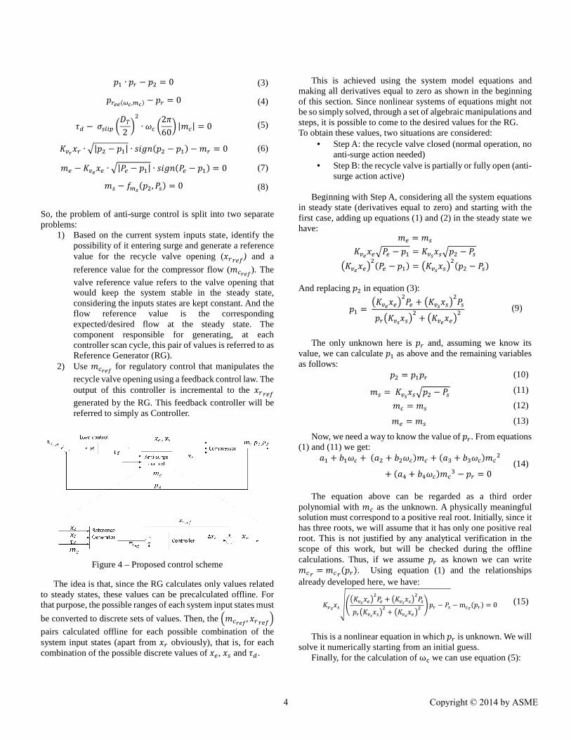
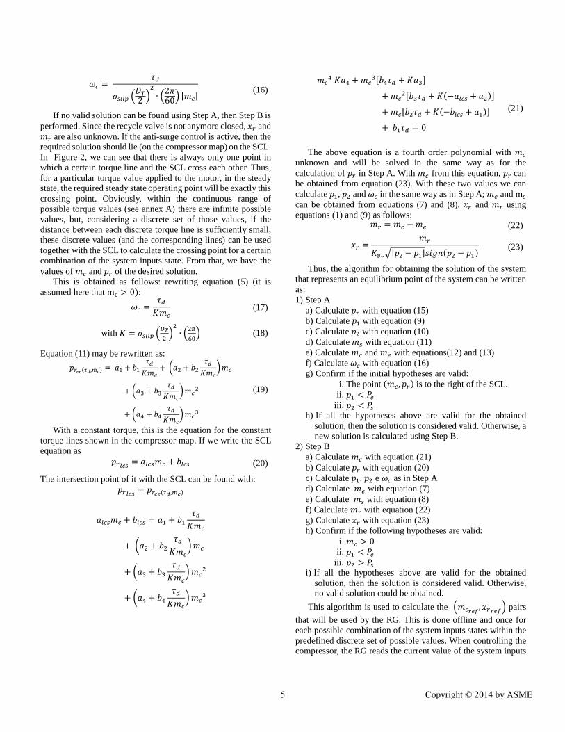
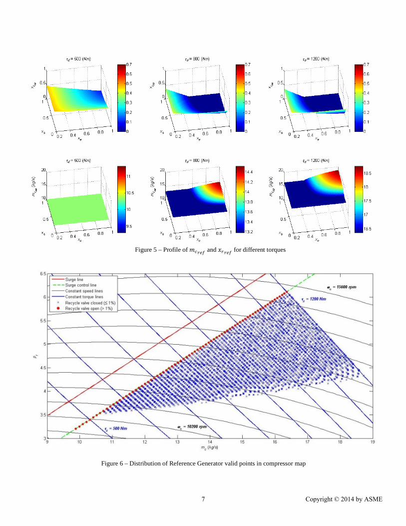
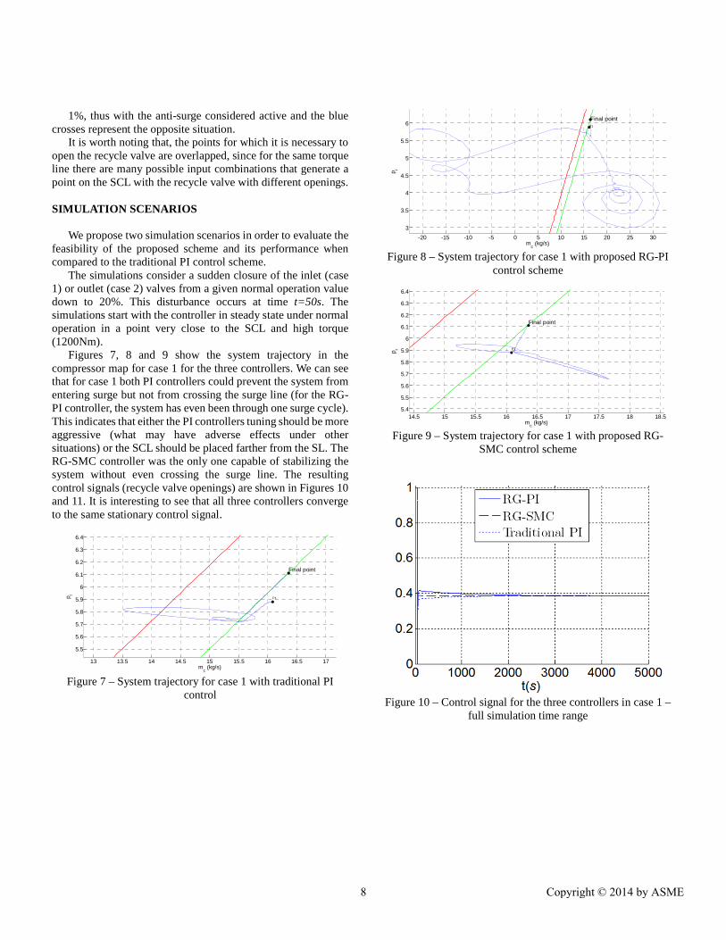
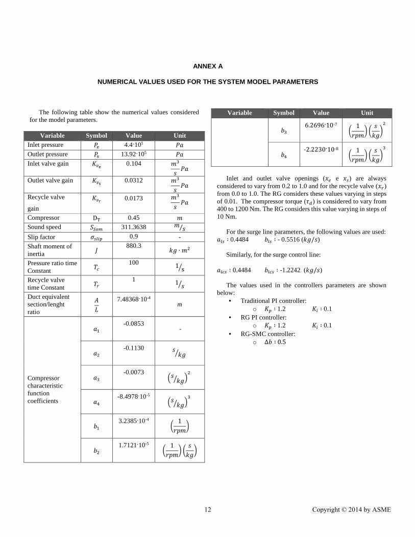