stdfdtn - verdebuild.comverdebuild.com/wp-content/uploads/Kingman-Geotech-Report-2.pdfmiles of...
25
Transcript of stdfdtn - verdebuild.comverdebuild.com/wp-content/uploads/Kingman-Geotech-Report-2.pdfmiles of...


Geotechnical Investigation Project No. 161265SA Native Grill & Wings August 17, 2016 – Page 1
1.0 INTRODUCTION
This report presents the results of a subsoil investigation carried out at the site of the proposed Native Bar & Grill to be constructed at the southwest corner of Stockton Hill Road & Plaza Drive in Kingman, Arizona.
We understand that construction will consist of a 6,800± square foot restaurant/retail building. The
building will be single story with slab on grade and masonry, wood frame or light steel gauge construction. Structural loads are expected to be light to moderate and no special considerations regarding settlement tolerances are known at this time. Adjacent areas will be landscaped or paved to support moderate passenger and light truck traffic. Landscaped areas and will be utilized for storm water retention and disposal.
2.0 GENERAL SITE AND SOIL CONDITIONS
2.1 Site Conditions
The property is bounded on the north by Plaza Drive followed by a Ford dealership, on the east by Stockton Hill Road, on the south by a retail building, and on the west by vacant land. The site is currently vacant with desert weeds and brush. The property appears to have been cleared and graded in the late 1990s to early 2000s and has since remained vacant. Refer to the following historical aerial photos:
Figure 2.1.1 Dated 1997 Figure 2.1.2 Dated 2003 Figure 2.1.3 Dated 2015

Geotechnical Investigation Project No. 161265SA Native Grill & Wings August 17, 2016 – Page 2
2.2 Seismic Design Parameters
The project area is located in a seismic zone that is considered to have low to moderate historical seismicity. The USGS database shows that there is a 15% chance of a major earthquake, magnitude greater than 5.0, within 30 miles of Kingman, AZ within the next 50 years. The most recent earthquake within 30 miles of Kingman, AZ was a 2.9 Magnitude in March, 2015. The largest earthquake within 30 miles of Kingman, AZ was a 3.0 Magnitude in 1987. Liquefaction is not considered a concern due to the shallow depth of bedrock.
Although borings were not advanced to 100 feet, based on the nature of the subsoils
encountered in the borings and geology in the area, Site Class Definition, Class C may be used for design of the structures. In addition, the following seismic parameters may be used for design (based on 2008 USGS maps adopted by 2012 IBC):
Table 2.3.1 Seismic Parameters
MCE1 spectral response acceleration for 0.2 second period, SS: 0.256g MCE1 spectral response acceleration for 1.0 second period, S1: 0.083g
Site coefficient, Fa: 1.2 Site coefficient, Fv: 1.7
MCE1 spectral response acceleration adjusted for site class, SMS: 0.307g MCE1 spectral response acceleration adjusted for site class, SM1: 0.141g
5% Damped spectral response acceleration, SDS: 0.205g 5% Damped spectral response acceleration, SD1: 0.094g
NOTE1: MCE = maximum considered earthquake
2.3 General Subsurface Conditions
The native subsoils consisted primarily of clayey sand and silty sand to the depths of auger refusal on cobbles at 5.0 to 12.0 feet below existing grades. The structural borings were terminated by auger refusal on cobbles at depth of 10.5 to 12 feet. Subordinate amounts of gravel was also noted throughout the profile. Standard Penetration Resistance Test (SPT) ranged from 35 to 50+ blows per foot generally increasing with depth. No groundwater was encountered during this investigation. Based on visual and tactile observation, the upper soils were in a ‘dry to moist’ state at the time of the investigation.
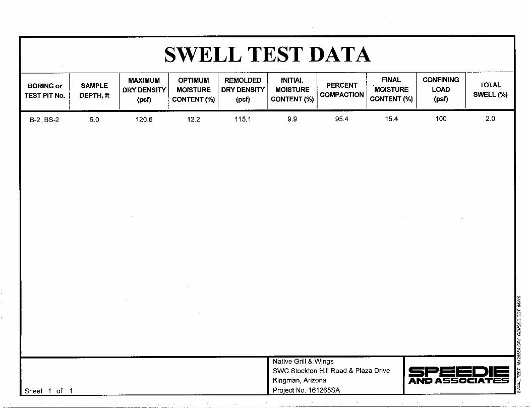
Laboratory testing indicates in-situ dry densities of the upper soils were 94 pcf and water
contents at 6.3 percent at the time of investigation. Liquid limits were at 30 to 31 percent with plasticity indices from 6 to 13. The upper clayey soils exhibit volume increase (swell) due to wetting of 2.0 percent when compacted to moisture and density levels normally expected during construction. Undisturbed

Geotechnical Investigation Project No. 161265SA Native Grill & Wings August 17, 2016 – Page 3
samples displayed moderate (3%) compression due to incremental loading and moderate (3.5%) additional compression due to inundation under a maximum confining load of 3,200 psf.
3.0 ANALYSIS AND RECOMMENDATIONS
3.1 Analysis
Analysis of the field and laboratory data indicates that subsoils at the site are generally favorable for the support of the proposed structures on shallow foundations and slab-on-grade construction. It is assumed that the overall site grade will remain essentially the same (± 1 foot).
The upper native soils in this area are susceptible to additional compression due to inundation. This could cause excessive settlement resulting in cracking problems. Accordingly, recommendations are made to over-excavate and recompact the bearing soils to increase density and reduce the potential for collapse. Attention must be paid to provide proper drainage to limit the potential for water infiltration of deeper soils.
An alternate to over-excavation and re-compaction is to deepen the foundations. Deeper
footings would be less likely to be inundated with moisture. Footings would also need to be deepened through any pad fill material if the pad will be raised more than 1 foot above current grades.
For standard foundations to perform as expected, attention must be paid to provide proper
drainage to limit the potential for water infiltration of deeper soils. It is assumed that the landscape plan will use mostly low water use or "green" desert type plants (xeriscape). It is preferred to keep irrigated plants at least 5 feet away from structures with irrigation schedules set and maintained to run intermittingly. Unpaved planter areas should be sloped at least 5 percent for a distance of at least 10 feet away from the building. It is understood that this may not be possible due to ADA maximum slope requirements for the adjacent sidewalks and patios. The slope may be reduced to 2 percent provided extra care is taken to ensure sidewalks and other hardscape features do not create a “dam” that prevents positive drainage away from the buildings, creating a "pond" adjacent to the building. Roof drainage should also be directed away from the building in paved scuppers. Pre-cast loose splash blocks should not be used as they can be dislodged and/or eroded. Roof drains should not be allowed to discharge into planters adjacent to the structure. It is preferred that they be directed to discharge to pavement (per photo example), retention basins or discharge points located at least 10 feet away from the building.

Geotechnical Investigation Project No. 161265SA Native Grill & Wings August 17, 2016 – Page 4
It is reiterated that shallow spread footings are recommended for the exterior walls and other light interior columns since this is the most economical system available. However, this shallow system relies on the dry strength of the unsaturated native soils. A limited depth of re-compaction is recommended to increase density of the near surface soils that are more likely to encounter seasonal moisture changes, or deeper foundations. The deeper native soils may be moisture sensitive and could experience differential settlement if subjected to significant surface water infiltration. Recognizing the need to minimize significant water penetration adjacent to the building perimeter that could detrimentally impact the building foundation, the following additional recommendations are made to protect foundations:
1. Take extra precaution to backfill and compact native soil fill to 95 percent in all exterior wall locations.
2. Create and maintain positive drainage away from the exterior wall for a minimum of 10 feet. 3. Avoid sidewalks, curbs or other elements that create a dam that could cause water to pond within 5
feet of the perimeter wall. 4. Include no irrigated landscape materials in the first 3 feet next to the building. 5. Between 3 feet and 5 feet, include only landscape materials that can be irrigated with a maximum of
1 gallon per hour emitter heads. Set and maintain irrigation controllers to prevent 24/7 flows. 6. Any landscape materials requiring greater than 1 gallon per hour irrigation, including turf, shall be at
least 5 feet from the outside face of the building. 7. All irrigation feeder lines, other than those that supply individual emitters, shall not be placed closer
than 5 feet to the building. Ground water is not expected to be a factor in the design or construction of shallow
foundations and underground utilities. Excavation operations may be difficult due to very dense, rocklike conditions. It should be noted that the fact that a boring was advanced to a particular depth should not lead to the assumption that it is necessarily excavatable by conventional means. Very dense and/or rocky conditions may require more aggressive rock removal techniques. The contractor should be responsible for determining what equipment will be required to make excavations.
For exterior slabs-on-grade, frequent jointing is recommended to control cracking and reduce
tripping hazards should differential movement occur. It is also recommended to pin the landing slab to the building floor/stem wall. This will reduce the potential for the exterior slab lifting and blocking the operation of out-swinging doors. Pinning typically consists of 24-inch long No. 4 reinforcing steel dowels placed at 12-inch centers.

Geotechnical Investigation Project No. 161265SA Native Grill & Wings August 17, 2016 – Page 5
3.2 Site Preparation The entire area to be occupied by the proposed construction should be stripped of all
vegetation, debris, rubble and obviously loose surface soils. Sufficient additional soil should be removed to provide space for the 12 inches of non-expansive fill.
If the option to over-excavate and re-compact to increase density is selected (Alternate A),
subsoils should be over-excavated at least 2 feet below proposed footing bottom elevation, or existing grade, whichever is deeper, extending at least 5 feet beyond the footing edges within all footing areas. It may be more feasible to just over-excavate the entire building pad if the building footprint is relatively small. A representative of the Geotechnical Engineer should examine the subgrade once sub-excavation is complete and prior to backfilling to ensure removal of deleterious materials. Fill placement and quality should be as defined in the "Fill and Backfill" section of this report.
Prior to placing structural fill below footing bottom elevation, the exposed grade should be scarified to a depth of 8 inches, moisture-conditioned to optimum (±2 percent) and compacted to at least 95 percent of maximum dry density as determined by ASTM D-698. Pavement areas should be scarified, moisture-conditioned and compacted in a similar manner.
All cut areas and areas above footing bottom elevation that are to receive floor slab only fill
should be scarified 8 inches, moisture conditioned to at least optimum to 3 percent above optimum and lightly but uniformly compacted to 90 but not more than 95 percent of maximum dry density as determined by ASTM D-698.
3.3 Foundation Design The following bearing capacities can be utilized for design:

Geotechnical Investigation Project No. 161265SA Native Grill & Wings August 17, 2016 – Page 6
Table 3.3.1 Foundation Bearing Capacities
Structure Foundation Type
Foundation Depth(1)
Bearing Medium Bearing Capacity
Comments
Minor Structures Spread 1.5 ft. Native Soils 1,250 psf 2 Main
Structure Spread 1.5 ft. Engineered Fill 2,500 psf 3 Spread 2.5 ft. Dense Native Soils 5,000 psf 4
Comments: 1. Foundation Depth refers to minimum depth below existing grade or slab level, or finished exterior
grade, whichever is greater. 2. For minor structures such as screen walls, planter walls, etc. not connected to any main structure.
Compaction of the subgrade to 95 percent standard proctor to at least 8 inches depth is required. 3. Footings to bear on minimum of 2’ of engineered fill + 8” pre-compacted subgrade. 4. Shallow spread footings bearing on dense undisturbed native soils at a minimum of 2.5 feet below
lowest finished exterior grade. These bearing capacities refer to the total of all loads, dead and live, and are net pressures.
They may be increased one-third for wind, seismic or other loads of short duration. All footing excavations should be level and cleaned of all loose or disturbed materials. Positive drainage away from the proposed buildings must be maintained at all times.
Continuous wall footings and isolated rectangular footings should be designed with minimum
widths of 16 and 24 inches respectively, regardless of the resultant bearing pressure. Lightly loaded interior partitions (less than 800 plf) may be supported on reinforced thickened slab sections (minimum 12 inches of bearing width).
Estimated settlements under design loads are on the order of ½ to ¾ -inch, virtually all of
which will occur during construction. Post-construction differential settlements will be on the order of one-half the total settlement, under existing and compacted moisture contents. Additional localized settlements of the same magnitude could occur if native supporting soils were to experience a significant increase in moisture content. Positive drainage away from structures and controlled routing of roof runoff must be provided and maintained to prevent ponding adjacent to perimeter walls. Planters requiring heavy watering should not be placed adjacent to or within 5 feet of the building. Care should be taken in design and construction to insure that domestic and interior storm drain water is contained to prevent seepage. Roof drainage should be directed to paved areas or storm drains. They should not discharge into planters adjacent to the structures.

Geotechnical Investigation Project No. 161265SA Native Grill & Wings August 17, 2016 – Page 7
Continuous footings and stem walls should be reinforced to distribute stresses arising from small differential movements, and long walls should be provided with control joints to accommodate these movements. Reinforcement and frequent control joints are suggested to allow slight movement and prevent minor floor slab cracking especially in floor areas to be covered with hard tile.
3.4 Lateral Pressures The following lateral pressure values may be utilized for the proposed construction:
Active Pressures Unrestrained Walls 35 pcf At-Rest Pressures Restrained Walls 60 pcf Passive Pressures
Continuous Footings 300 pcf Spread Footings or Drilled Piers 350 pcf
Coefficient of Friction (w/ passive pressure) 0.35 Coefficient of Friction (w/out passive pressure) 0.45
All backfill must be compacted to not less than 95 percent (ASTM D-698) to mobilize these
passive values at low strain. Expansive soils should not be used as retaining wall backfill, except as a surface seal to limit infiltration of storm/irrigation water. The expansive pressures could greatly increase active pressures.
3.5 Fill and Backfill
Native soils are considered suitable for use in general grading fills, engineered fills, and wall backfill provided oversized material (greater than 3 inches) is screened out for fill placed within 3 feet of pad elevation. Some oversized material (up to 12 inches) is acceptable in the deeper fills provided the contractor can demonstrate proper placement and compaction effort. Sufficient fines should be mixed into the matrix to prevent nesting of cobbles creating void spaces.
The silty fine sand soils may be sensitive to excessive moisture content and will become
unstable at elevated moisture content. Accordingly, it may be necessary to compact soils on the dry side of optimum, especially in asphalt pavement areas. The reduced moisture content under slabs-on-grade should only be used upon approval of the engineer in the field.

Geotechnical Investigation Project No. 161265SA Native Grill & Wings August 17, 2016 – Page 8
Imported common fill for use in site grading should be examined by a Soils Engineer to ensure that it is of low swell potential and free of organic or otherwise deleterious material. In general, the fill should have 100 percent passing the 3-inch sieve and no more than 60 percent passing the 200 sieve. For the fine fraction (passing the 40 sieve), the liquid limit and plasticity index should not exceed 30 percent and 10 percent, respectively. It should exhibit less than 1.5 percent swell potential when compacted to 95 percent of maximum dry density (ASTM D-698) at a moisture content of 2 percent below optimum, confined under a 100 psf surcharge, and inundated.
Fill should be placed on subgrade which has been properly prepared and approved by a Soils
Engineer. Fill must be wetted and thoroughly mixed to achieve optimum moisture content, ±2 percent. Fill should be placed in horizontal lifts of 8-inch thickness (or as dictated by compaction equipment) and compacted to the percent of maximum dry density per ASTM D-698 set forth as follows:
A. Building Areas 1. Below footing level 95 2. Below slabs-on-grade (non-expansive soils) 95 3. Below slabs-on-grade (expansive soils) 90-95 (max) (Not recommended for the top 12-inches Pad) B. Pavement Subgrade or Fill 95 C. Utility Trench Backfill 95 D. Aggregate Base Course
1. Below floor slabs 95 2. Below asphalt paving 100
E. Landscape Areas 90
3.6 Utilities Installation Trench excavations for utilities can be accomplished by conventional trenching equipment
although cobble laden soils may impede progress and require the use of heavier equipment. The fact that a boring or test pit was advanced to a certain depth does not mean that the soils may be excavated by normal means. The excavating contractor must make his/her own assessment as to excavatability. Trench walls should stand near-vertical for the short periods of time required to install shallow utilities although some sloughing may occur in looser and/or sandier soils requiring laying back of side slopes and/or temporary shoring. Adequate precautions must be taken to protect workmen in accordance with all current governmental regulations.
Backfill of trenches above bedding zones may be carried out with native excavated material
provided over-sized materials (+6 inches) are removed. This material should be moisture-conditioned, placed

Geotechnical Investigation Project No. 161265SA Native Grill & Wings August 17, 2016 – Page 9
in 8-inch lifts and mechanically compacted. Water settling is not recommended. Compaction requirements are summarized in the "Fill and Backfill" section of this report.
3.7 Slabs-On-Grade To facilitate fine grading operations and aid in concrete curing, a 4-inch thick layer of
granular material conforming to the gradation for Aggregate Base (A.B.) as per M.A.G. Specification Section 702 should be utilized beneath the slab. Dried subgrade soils must be re-moistened prior to placing the aggregate base if allowed to dry out, especially if fine-grained soils are used in the top 12-inches of the pad.
The native soils are capable of storing a significant amount of moisture, which could increase
the natural vapor drive through the slab. Accordingly, if moisture sensitive flooring and/or adhesive are planned, the use of a vapor barrier directly under the slab is recommended. Vapor barriers should be a minimum 15-mil thick polyolefin (or equivalent), which meets ASTM E 1745 Class A specifications. Vapor barriers do increase the potential for slab curling and water entrapment under the slab. Accordingly, if a vapor barrier is used, additional precautions such as low slump concrete, frequent jointing and proper curing will be required to reduce curling potential and detailed to prevent the entrapment of outside water sources.
3.8 Asphalt Concrete Pavement
If earthwork in paved areas is carried out to finish subgrade elevation as set forth herein, the subgrade will provide adequate support for pavements. The location designation is for reference only. The designer/owner should choose the appropriate sections to meet the anticipated traffic volume and life expectancy. The section capacity is reported as daily ESALs, Equivalent 18 kip Single Axle Loads. Typical heavy trucks impart 1.0 to 2.5 ESALs per truck depending on load. It takes approximately 1,200 passenger cars to impart 1 ESAL.
Pavement Design Parameters: Assume: One 18 kip Equivalent Single Axle Load (ESAL)/Truck Life: 20 years Subgrade Soil Profile:
% Passing #200 sieve: 27% Plasticity Index: 10 k: 175 pci (assumed) R value: 49 (per ADOT tables) MR: 26,000 (maximum allowed per AASHTO design)
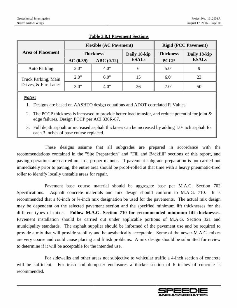
Geotechnical Investigation Project No. 161265SA Native Grill & Wings August 17, 2016 – Page 10
Table 3.8.1 Pavement Sections
Area of Placement Flexible (AC Pavement) Rigid (PCC Pavement)
Thickness Daily 18-kip ESALs
Thickness Daily 18-kip ESALs AC (0.39) ABC (0.12) PCCP
Auto Parking 2.0" 4.0" 6 5.0" 9
Truck Parking, Main Drives, & Fire Lanes
2.0" 6.0" 15 6.0" 23
3.0" 4.0" 26 7.0" 50
Notes: 1. Designs are based on AASHTO design equations and ADOT correlated R-Values.
2. The PCCP thickness is increased to provide better load transfer, and reduce potential for joint & edge failures. Design PCCP per ACI 330R-87.
3. Full depth asphalt or increased asphalt thickness can be increased by adding 1.0-inch asphalt for each 3 inches of base course replaced.
These designs assume that all subgrades are prepared in accordance with the
recommendations contained in the "Site Preparation" and "Fill and Backfill" sections of this report, and paving operations are carried out in a proper manner. If pavement subgrade preparation is not carried out immediately prior to paving, the entire area should be proof-rolled at that time with a heavy pneumatic-tired roller to identify locally unstable areas for repair.
Pavement base course material should be aggregate base per M.A.G. Section 702 Specifications. Asphalt concrete materials and mix design should conform to M.A.G. 710. It is recommended that a ½-inch or ¾-inch mix designation be used for the pavements. The actual mix design may be dependent on the selected pavement section and the specified minimum lift thicknesses for the different types of mixes. Follow M.A.G. Section 710 for recommended minimum lift thicknesses. Pavement installation should be carried out under applicable portions of M.A.G. Section 321 and municipality standards. The asphalt supplier should be informed of the pavement use and be required to provide a mix that will provide stability and be aesthetically acceptable. Some of the newer M.A.G. mixes are very coarse and could cause placing and finish problems. A mix design should be submitted for review to determine if it will be acceptable for the intended use.
For sidewalks and other areas not subjective to vehicular traffic a 4-inch section of concrete will be sufficient. For trash and dumpster enclosures a thicker section of 6 inches of concrete is recommended.

Geotechnical Investigation Project No. 161265SA Native Grill & Wings August 17, 2016 – Page 11
Portland Cement Concrete Pavement must have a minimum 28-day flexural strength 550 psi
(compressive strength of approximately 3,700 psi). It may be cast directly on the prepared subgrade with proper compaction (reduced) and the elevated moisture content as recommended in the report. Lacking an aggregate base course, attention must be paid to using low slump concrete and proper curing, especially on the thinner sections. No reinforcing is necessary. Joint design and spacing should be in accordance with ACI recommendations. Construction joints should contain dowels or be tongue-and-grooved to provide load transfer. Tie bars are recommended on the joints adjacent to unsupported edges. Maximum joint spacing in feet should not exceed 2 to 3 times the thickness in inches. Joint sealing with a quality silicone sealer is recommended to prevent water from entering the subgrade allowing pumping and loss of support.
Proper subgrade preparation and joint sealing will reduce (but not eliminate) the potential for slab movements (thus cracking) on the expansive native soils. Frequent jointing will reduce uncontrolled cracking and increase the efficiency of aggregate interlock joint transfer.
4.0 GENERAL The scope of this investigation and report includes only regional published considerations for seismic
activity and ground fissures resulting from subsidence due to groundwater withdrawal, not any site specific studies. The scope does not include any considerations of hazardous releases or toxic contamination of any type.
Our analysis of data and the recommendations presented herein are based on the assumption that soil
conditions do not vary significantly from those found at specific sample locations. Our work has been performed in accordance with generally accepted engineering principles and practice; this warranty is in lieu of all other warranties expressed or implied.


FIELD AND LABORATORY INVESTIGATION
On July 19, 2016, soil test borings were drilled at the approximate locations shown on the attached Soil Boring Location Plan. All exploration work was carried out under the full-time supervision of our senior soils technician, who recorded subsurface conditions and obtained samples for laboratory testing. The soil borings were advanced with a truck-mounted CME-75 drill rig utilizing 7-inch diameter hollow stem flight augers. Detailed information regarding the borings and samples obtained can be found on an individual Log of Test Boring prepared for each drilling location.
Laboratory testing consisted of moisture content, dry density, grain-size distribution and plasticity
(Atterberg Limits) tests for classification and pavement design parameters. Remolded swell tests were performed on samples compacted to densities and moisture contents expected during construction. Compression tests were performed on a selected ring sample in order to estimate settlements and determine effects of inundation. All field and laboratory data is presented in this appendix.


SW
PEAT, HUMUS, SWAMP SOILS WITHHIGH ORGANIC CONTENTS
GRAVELS WITHFINES
(LITTLE OR NO FINES)
CLEANGRAVELS
HIGHLY ORGANIC SOILS
SILTSAND
CLAYS
SILTSAND
CLAYS
MORE THAN 50% OFCOARSE FRACTIONPASSING ON NO. 4SIEVE
SANDAND
SANDYSOILS
MORE THAN 50% OFCOARSE FRACTIONRETAINED ON NO. 4SIEVE
GRAVELAND
GRAVELLYSOILS
MORE THAN 50% OFMATERIAL ISSMALLER THAN NO.200 SIEVE SIZE
FINEGRAINED
SOILS
MAJOR DIVISIONS
LIQUID LIMITGREATER THAN 50
LIQUID LIMITLESS THAN 50
(APPRECIABLE AMOUNTOF FINES)
SANDS WITHFINES
MH
OL
CL
ML
SC
SM
SP
WELL-GRADED GRAVELS, GRAVEL -SAND MIXTURES, LITTLE OR NO FINES
TYPICALLETTERGRAPH
SYMBOLS
ORGANIC CLAYS OF MEDIUM TO HIGHPLASTICITY, ORGANIC SILTS
INORGANIC CLAYS OF HIGHPLASTICITY
(LITTLE OR NO FINES)
CLEAN SANDS
(APPRECIABLE AMOUNTOF FINES)
MORE THAN 50% OFMATERIAL ISLARGER THAN NO.200 SIEVE SIZE
COARSEGRAINED
SOILS
INORGANIC SILTS, MICACEOUS ORDIATOMACEOUS FINE SAND OR SILTYSOILS
ORGANIC SILTS AND ORGANIC SILTYCLAYS OF LOW PLASTICITY
INORGANIC CLAYS OF LOW TOMEDIUM PLASTICITY, GRAVELLYCLAYS, SANDY CLAYS, SILTY CLAYS,LEAN CLAYS
INORGANIC SILTS AND VERY FINESANDS, ROCK FLOUR, SILTY ORCLAYEY FINE SANDS OR CLAYEYSILTS WITH SLIGHT PLASTICITY
CLAYEY SANDS, SAND - CLAYMIXTURES
SILTY SANDS, SAND - SILT MIXTURES
POORLY-GRADED SANDS, GRAVELLYSAND, LITTLE OR NO FINES
WELL-GRADED SANDS, GRAVELLYSANDS, LITTLE OR NO FINES
CLAYEY GRAVELS, GRAVEL - SAND -CLAY MIXTURES
SILTY GRAVELS, GRAVEL - SAND -SILT MIXTURES
POORLY-GRADED GRAVELS, GRAVEL- SAND MIXTURES, LITTLE OR NOFINES
PT
OH
CH
GC
GM
GP
GW
DESCRIPTIONS
NOTE: DUAL OR MODIFIED SYMBOLS MAY BE USED TO INDICATE BORDERLINE SOILCLASSIFICATIONS OR TO PROVIDE A BETTER GRAPHICAL PRESENTATION OF THE SOIL
Very SoftSoftFirmStiff
Very StiffHard
0 - 22 - 45 - 8
9 - 1516 - 30
> 30
0 - 0.250.25 - 0.50.5 - 1.0
1 - 22 - 4> 4
Very LooseLoose
Medium DenseDense
Very Dense
0 - 45 - 10
11 - 3031 - 50
> 50
Clays & Silts Blows/Foot Strength (tons/sq ft) Sands & Gravels Blows/Foot
CONSISTENCY RELATIVE DENSITY
0.0750.4202.000
4.7519
75
300
0.422.004.75
1975
300
900
#200#40#10
#40.75"
#40#10#4
0.75"3"
3"
12"
12"
36"
mmmmLower Limit Upper Limit
PARTICLE SIZEMATERIAL
SIZE
SANDSFine
MediumCoarse
GRAVELSFine
Coarse
COBBLES
BOULDERS
Sieve Size Sieve Size
U.S. Standard Clear Square Openings
50
60
00
10
80 100Liquid Limit
30
40
CL-ML
CL
20
20 40 60
CH
B-Line
A-Line
ML & OL
MH & OH
Plasticity Index
A grab sample taken directly from auger flights.
A grab sample taken from auger spoils or from bucket of backhoe.
Standard Penetration Test (ASTM D-1586) Driving a 2.0 inch outside diameter splitspoon sampler into undisturbed soil for three successive 6-inch increments bymeans of a 140 lb. weight free falling through a distance of 30 inches. Thecumulative number of blows for the final 12 inches of penetration is the StandardPenetration Resistance.
Driving a 3.0 inch outside diameter spoon equipped with a series of 2.42-inch insidediameter, 1-inch long brass rings, into undisturbed soil for one 12-inch increment bythe same means of the Spoon Sample. The blows required for the 12 inches ofpenetration are recorded.
Standard Penetration Test driving a 2.0-inch outside diameter split spoon equippedwith two 3-inch long, 3/8-inch inside diameter brass liners, separated by a 1-inchlong spacer, into undisturbed soil by the same means of the Spoon Sample.
A 3.0-inch outside diameter thin-walled tube continuously pushed into theundisturbed soil by a rapid motion, without impact or twisting (ASTM D-1587).
Driving a 2.0-inch outside diameter "Bullnose Penetrometer" continuously intoundisturbed soil by the same means of the spoon sample. The blows for eachsuccessive 12-inch increment are recorded.
DESCRIPTION
Auger SampleAS
BS Large Bulk Sample
S Spoon Sample
RS Ring Sample
LS Liner Sample
ST Shelby Tube
ContinuousPenetrationResistance
--
DESIGNATIONSAMPLE
SOIL LEGEND