Std Plans and Specifications Cover - Marina Coast … or other facilities and structures that may be...
157
STANDARD PLANS AND SPECIFICATIONS FOR CONSTRUCTION OF DOMESTIC WATER, SEWER AND RECYCLED WATER FACILITIES Marina Coast Water District 11 Reservation Road Marina, CA 92933 (831) 582-2665
Transcript of Std Plans and Specifications Cover - Marina Coast … or other facilities and structures that may be...
STANDARD PLANS AND SPECIFICATIONS FOR CONSTRUCTION OF
DOMESTIC WATER, SEWER AND RECYCLED WATER FACILITIES
Marina Coast Water District 11 Reservation Road Marina, CA 92933
(831) 582-2665

MARINA COAST WATER DISTRICT
NOVEMBER 2007 TOC-1
TABLE OF CONTENTS STANDARD SPECIFICATIONS Section Description
01045 Existing Facilities
02200 Structure Earthwork
02222 Abandonment of Pipelines
02223 Trenching, Backfilling and Compacting
02315 Jacked Casing
02701 Installation of Gravity Sewer Pipelines
02715 PVC Gravity Sewer Pipe
03300 Concrete
03461 Precast Reinforced Concrete Manholes and Manhole Bases
03462 Precast Concrete Vaults
03463 Grease Interceptors
09900 Painting and Coating
13110 Corrosion Protection and Joint Bonding
15041 Chlorination of Domestic Water Mains and Services for Disinfection
15042 Hydrostatic Testing of Pressure Pipelines
15043 Leakage and Infiltration in Testing of Non-Pressure Pipelines
15050 Hot Tap Connections
15056 Ductile-Iron Pipe and Fittings
15057 Copper, Brass, and Bronze Pipe, Fittings and Appurtenances
15058 Polyethylene Pipe
15064 PVC Pressure Distribution Pipe
15089 Combination Air and Vacuum Release Valve Assembly
15100 Manual Valves
15112 Backflow Preventers
15139 Fire Hydrants
15150 Meters
15151 Underground Facilities Identification
15162 Flexible Pipe Couplings and Expansion Joints
15300 Automatic Control Valves
22000 Hot Water Heaters, Hot Water Recirculation Systems and Point of Use Water Heaters
22100 Water Conserving Appliances and Fixtures

MARINA COAST WATER DISTRICT
OCTOBER 2007 01045-1
STANDARD SPECIFICATIONS
SECTION 01045
EXISTING FACILITIES PART 1 - GENERAL A. Description This section includes requirements for connection to and abandonment of existing District facilities. B. Related Work Specified Elsewhere All related work specified elsewhere, or in other codes or standards, will be as last revised, unless a
specific date of issuance is called out in opposition to later revision date(s). Other sections of the technical specifications, not referenced below, shall also apply to the extent
required for proper performance of this work. 1. Abandonment of Pipelines 02222 2. Trenching, Backfilling, and Compacting: 02223 3. Chlorination of Domestic Water Mains and Services for Disinfection: 15041 4. Hydrostatic Testing of Pressure Pipelines: 15042 5. Hot Tap Connections 15050 6. Manual Valves: 15100 C. Condition of Existing Facilities The District does not warranty the condition, size, material, and location of existing facilities. D. Location The contractor shall be responsible for potholing and verifying in advance the location of all
existing pipelines as shown on the plans. Discrepancies shall be reported to the project engineer, prior to the fabrication of, or purchase of material affected by the discrepancy.
E. Protection of Existing Utilities and Facilities 1. The contractor shall be responsible for the care and protection of all existing sewer pipe,
water pipe, gas mains, culverts, power or communications lines, sidewalks, curbs, pavement, or other facilities and structures that may be encountered in or near the area of the work.

MARINA COAST WATER DISTRICT
OCTOBER 2007 01045-2
2. It shall be the duty of the contractor to notify Underground Service Alert and each agency of jurisdiction and make arrangements for locating their facilities prior to beginning construction.
3. In the event of damage to any existing facilities during the progress of the work, the contractor shall pay for the cost of all repairs and protection to said facilities. The contractor's work may be stopped until repair operations are complete.
4. Any existing water and sewer pipe to be abandoned and remain in place shall be allowed
with approval of the City or County. The contractor shall seek all approvals to allow existing water and sewer lines to be abandoned in place. Abandoned water and sewer pipe is not the property of Marina Coast Water District and is the property of the developer or the property of the fee title owner to the development property.
F. Protection of Landscaping 1. The contractor shall be responsible for the protection of all the trees, shrubs, irrigation
systems, fences, and other landscape items adjacent to or within the work area, unless they are directed to do otherwise on the plans.
2. In the event of damage to landscape items, the contractor shall replace the damaged items
to the satisfaction of the engineer and the owner, or pay damages to the owner as directed by the District.
3. When the proposed pipeline is to be within planted or other improved areas in public or
private easements, the contractor shall restore such areas to the original condition after completion of the work. This restoration shall include grading, a placement of 5 inches of good topsoil, resoding, and replacement of all landscape items indicated.
4. If the contractor does not proceed with the restoration after completion of the work or does
not complete the restoration in a satisfactory manner, the engineer reserves the right to have the work done and to charge the contractor for the actual cost of the restoration including all labor, material, and overhead required for restoration.
G. Permits All work shall conform to the specifications and requirements of the State of California Department
of Transportation, the County, the city having jurisdiction, or the other affected agencies involved. The contractor shall keep a copy of all the required permits in the job site and comply with all the terms and conditions of said permits. Permits shall also include any related to the abandonment of an existing water or sewer pipe.
PART 2 - MATERIALS All materials used in making the connection or removing the facility from service shall conform to the applicable sections of these specifications. A. Grout Grout shall consist of Portland cement and water or of Portland cement, sand, and water; and all
grout mixtures shall contain 2% of bentonite by weight of the cement. Grout shall be a pump mix with a minimum of six sacks cement (564 lbs) per cubic yard.

MARINA COAST WATER DISTRICT
OCTOBER 2007 01045-3
Portland cement, water and sand shall conform to the applicable requirements of the concrete section (Section 03300), except that sand to be used shall be of such fineness that 100% will pass a standard 8-mesh sieve and at least 45%, by weight, will pass a standard 40-mesh sieve.
B. Concrete
Concrete used for the replacement of damaged or removed facilities shall be in accordance with Section 03300 and shall match the mix design of the existing facility and per the requirement of the jurisdictional agency.
PART 3 - EXECUTION A. Connection to Existing Facilities 1. All connections shall be made by the contractor unless shown otherwise on the plans or
specified herein.
2. If multiple connections to the District’s water/recycled water/sewer system are anticipated, the contractor shall submit a connection plan developed with the intent of minimizing the down time to District customers and will be reviewed and approved by the District.
3. When customers are affected, the contractor shall notify the district a minimum of seven
working days before the time of any proposed shutdown of existing mains or services. The District inspector may postpone or reschedule any shutdown operation if for any reason he feels that the contractor is improperly prepared with competent personnel, equipment, or materials to proceed with the connection work.
4. When no customers are affected, the contractor shall notify the District a minimum of two
working days before the time of any proposed shutdown of existing mains or services. The District inspector may postpone or reschedule any shutdown operation if for any reason he feels that the contractor is improperly prepared with competent personnel, equipment, or materials to proceed with the connection work.
5. Connections shall be made only in the presence of the District, and no connection work
shall proceed until the engineer has given notice to proceed. If progress is inadequate during the connection operations to complete the connection in the time specified, the engineer shall order necessary corrective measures. All costs for corrective measures shall be paid by the contractor.
6. The contractor shall furnish all pipe and materials including furnishing all labor and
equipment necessary to make the connections, all required excavation, backfill, pavement replacement, lights, and barricades, and may be required to include a water truck, high line hose, and fittings as part of this equipment for making the connections. In addition, the contractor shall assist the District in alleviating any hardship incurred during the shutdown for connections. Standby equipment or materials may be required by the engineer.
7. The contractor shall de-water existing mains, as required, in the presence of the engineer. 8. Prior to tapping or cutting an existing pipe: a. Locate all existing isolation valves required for the Work. b. Test the existing isolation valves a minimum of 3 days prior to the Work.

MARINA COAST WATER DISTRICT
OCTOBER 2007 01045-4
c. If the valves cannot be operated, Contractor shall meet with the owner and Engineer to determine if the valves must be replaced, or if plugs can be used for the Work.
9. Prior to disconnecting any flanged connection, if reconnection is required as part of the
Work: a. Locate all flanged connections a minimum of two days before the Work. b. A minimum of one day before the Work, expose the flanged connection(s).
Remove and inspect each flange bolt, one at a time so as not to break the piping connection. If serviceable, clean the bolt with a wire brush and reinstall on the flange. If not serviceable, replace with a new bolt set (bolt, nut and washers) of the appropriate type.
c. During the Work, replace the flange gasket and install new bolt sets throughout. 10. Prior to disconnecting any electrical or control equipment (for replacement): a. Locate all control devices and wiring a minimum of two days before the work. b. Review wiring and termination diagrams for the existing and replacement
equipment. c. Label (tag) all wiring to remain to facilitate identification during the installation.
Annotate changes on the wiring diagrams, if needed. d. Pull all new cables and wires though conduits prior to the scheduled outage, to the
extent possible. e. Coordinate any changes to the control system with the Owner and Engineer in
advance, so that SCADA programming is adjusted as needed. 11. Connections shall be made with as little change as possible in the grade of the new main. If
the grade of the existing pipe is below that of the new pipeline, a sufficient length of the new line shall be deepened so as to prevent the creation of any high spot or abrupt changes in grade of the new line. Where the grade of the existing pipe is above that of the new pipeline, the new line shall be laid at specified depth, except for the first joint adjacent to the connection, which shall be deflected within the allowances of the pipe manufacturer as necessary to meet the grade of the existing pipe. If sufficient change in direction cannot be obtained by the limited deflection of the first joint, a fitting of the proper angle shall be installed. Where the connection creates a high or low spot in the line, a standard air release or blow off assembly shall be installed as directed by the engineer.
12. Where connections are made to existing valves, the contractor shall furnish and install all
temporary blocking, steel clamps, shackles, and anchors as required by the District, and he shall replace the valve riser box and cover and adjust the valve cover to the proper grade in accordance with these specifications. The District will operate all existing valves. All valves, existing or newly installed, shall be readily accessible at all times to the District for emergency operation.
13. New pipelines shall not be connected to existing facilities until the new pipelines have been
successfully tested, disinfected and accepted by the District. 14. Tapping connection can be made to the existing system while it is either in service or shut
down depending on the District’s prior direction. A tapping valve shall be used when the existing system is maintained in service during connection. Tapping shall be in accordance with the specification requirements for the pipe being tapped.

MARINA COAST WATER DISTRICT
OCTOBER 2007 01045-5
15. All saddle connections into existing sewer pipes shall be made with a wye saddle. Saddles shall conform to the applicable provisions of the section for the existing sewer pipe material.
B. Removal from Service of Existing Mains and Appurtenances 1. Existing mains and appurtenances shall be removed from service at the locations shown on
the plans or as directed by the engineer. 2. Abandoned pipe shall be filled with flowable fill in accordance with Section 02222. 3. Existing pipe and appurtenances removed from the ground will require backfill and repair
of surface in accordance with Section 02223. 4. Removed pipe and appurtenances shall be temporarily stockpiled on the job in a location
that will not disrupt traffic or be a safety hazard, disposed of in a proper manner (as determined by the engineer). The contractor shall remove and dispose of all removed pipe at his own expense to a landfill permitted to accept such materials.
5. Before excavating for installing mains that are to replace existing pipes and/or services, the
contractor shall make proper provisions for the maintenance and continuation of service as directed by the engineer unless otherwise specified.
6. If the meter box is to be removed from an abandoned water service, the service line is to be
removed and the corporation stop closed and capped. If there is no corporation stop on the service, the adapter is to be removed and a brass plug is to be installed in the service saddle.
7. Asbestos Cement Pipe (ACP) shall be cut, removed and disposed of in a proper manner.
The contractor shall be responsible for the proper manifesting of any and all ACP at an authorized disposal site.
C. Cutting and Restoring Street Surfacing. 1. In cutting or breaking up street surfacing, the contractor shall not use equipment that will
damage adjacent pavement. 2. All asphalt and/or Portland cement concrete surfaces shall be scored with sawing
equipment of a type meeting the approval of the District; providing however, that any cement concrete base under an asphaltic mix surface will not be required to be scored by sawing. Existing paving surfaces shall be saw cut back beyond the edges of the trenches to form neat square cuts before repaving is commenced.
3. Pavement, sidewalks, curbs, or gutters removed or destroyed in connection with
performance of the work shall be saw cut to the nearest score marks, if any, and shall be replaced with pavement sidewalks, curbs, or gutters of the same kind, or better by the contractor in accordance with the latest specifications, rules, and regulations and subject to the inspection of the agency having jurisdiction over the street or highway.
4. Aggregate base shall be placed beneath the restored pavement to the thickness required by
the agency having jurisdiction.
END OF SECTION

MARINA COAST WATER DISTRICT
SEPTEMBER 2003 02200-1
STANDARD SPECIFICATIONS
SECTION 02200
STRUCTURE EARTHWORK PART 1 - GENERAL A. Description This section includes excavation, backfilling, materials, testing, and shoring for structures. B. Related Work Specified Elsewhere All related work specified elsewhere, or in other codes or standards, will be as last revised, unless a
specific date of issuance is called out in opposition to later revision date(s). Other sections of the technical specifications, not referenced below, shall also apply to the extent
required for proper performance of this work. 1. Trenching, Backfilling, and Compacting: 02223 2. Concrete: 03300 C. Testing for Compaction Testing for compaction shall conform to Section 02223. D. Definition of Zones 1. Pavement and street zones shall be as specified in Section 02223. 2. Backfill zone is the backfill from the bottom of the structure excavation to the bottom of the
street zone in paved areas or to the existing surface in unpaved areas. E. Permits All work shall conform to the specifications and requirements of the State of California Department
of Transportation, the city having jurisdiction, or any other affected agencies involved. The contractor shall keep a copy of all the required permits in the job site and comply with all the terms and conditions of said permits.
F. Submittal
For any shoring or sheeting systems to be used for excavation, the contractor shall submit shoring
plans and calculations designed and sealed by a registered structural engineer in the State of California.

MARINA COAST WATER DISTRICT
SEPTEMBER 2003 02200-2
PART 2 - MATERIALS Native earth backfill, imported backfill material, granular material, imported sand, and crushed
rock shall conform to the requirements of Section 02223. PART 3 - EXECUTION A. Compaction Requirements 1. Backfill in Street Zone: 95% relative compaction 2. Structural Backfill: 95% relative compaction 3. Gravel Base: 95% relative compaction or as approved by the engineer 4. Adjacent to existing structures: 95% relative compaction B. Sidewalk, Pavement, and Curb Removal 1. Saw cut bituminous or concrete pavements regardless of their thickness, and curbs and
sidewalks prior to excavation for the structure in accordance with the requirements of the city, or agency having jurisdiction. Curbs and sidewalks, that are damaged in the course of construction, are to be cut and removed from joint to joint.
2. Haul removed pavement and concrete materials from the site, to a proper disposal
facility. These materials are not permitted for use as backfill. If the material to be removed exceeds 50 cubic yards, the contractor shall obtain a haul route permit from the city(s) having jurisdiction.
C. De-watering 1. Provide and maintain means and devices to continuously remove and dispose of all
water entering the excavation during construction of the structure and all backfill operations.
2. Dispose of the water in a manner to prevent damage to adjacent property and pipe
trenches. 3. Do not allow water to rise in the excavation until backfilling around and above the
structure is completed. 4. Reporting shall conform to the requirements of the District's NPDES permit. A copy of
the District’s permit is available from the District. 5. In no event shall the sewer system be used as a drain for de-watering.

MARINA COAST WATER DISTRICT
SEPTEMBER 2003 02200-3
D. Structure Excavation 1. Structure excavation shall include the removal of all material of whatever nature
necessary for the construction of structures and foundations in accordance with the plans and these specifications.
2. The sides of excavations for structures shall be sufficient to leave at least a 2-foot
clearance, as measured from the extreme outside of form work or the structure, as the case may be.
3. Surplus material shall be disposed of by the contractor in accordance with Section
02223. E. Correction of Over Excavation 1. Where excavation is inadvertently carried below design depths, suitable provision shall
be made by the contractor to adjust construction, as directed by the District representative, to meet requirements incurred by the deeper excavation.
2. No earth backfill will be permitted to correct over excavation beneath structures. 3. Over excavation shall be corrected by backfilling with crushed rock or concrete, as
directed by the District representative. F. Bracing 1. The contractor's design and installation of bracing and sheeting shall take the necessary
precautions to be consistent with the rules, orders, and regulations of the State of California Construction Safety Orders.
2. Excavations shall be so braced, sheeted, and supported that they will be safe, such that
the walls of the excavation will not slide or settle and all existing improvements of any kind, either on public or private property, will be fully protected from damage.
3. The sheeting, shoring, and bracing shall be arranged so as not to place any stress on
portions of the completed work. 4. Carefully remove sheeting, shoring, bracing, and timbering to prevent the caving or
collapse of the excavation faces being supported. G. Backfill 1. After structures and foundations are in place, backfill shall be placed to the original
ground line or to the limits designated on the plans. 2. No material shall be deposited against concrete structures until the concrete has reached
a compressive strength of at least 3,000 pounds per square inch as tested per Section 03300.
3. Imported sand or granular material shall be placed in horizontal layers not exceeding 12
inches in depth.

MARINA COAST WATER DISTRICT
SEPTEMBER 2003 02200-4
4. Each layer of backfill material shall be moistened and thoroughly tamped, rolled, or otherwise compacted to the specified relative density.
5. Carefully operate compaction equipment near structures to prevent their displacement or
damage. Structural fill is to be placed and compacted in uniform layers around all sides of the structure.
6. One-sack cement slurry may be used as structural backfill material.
H. Pavement Replacement Pavement replacement shall be in accordance with the requirements of the city or the agency
having jurisdiction. I. Permits An Encroachment Permit from the city or agency having jurisdiction is required prior to any
work within public right-of-way. All traffic control and pavement replacement work shall be in accordance with the requirements of the permit and the agency Inspector.
A permit from OSHA is required of any excavation exceeding 5 feet. Follow all restrictions of the required permits from other agencies.
END OF SECTION

MARINA COAST WATER DISTRICT
OCTOBER 2007 02222-1
STANDARD SPECIFICATIONS
SECTION 02222
ABANDONMENT OF PIPELINES PART 1 - GENERAL A. Description This section includes abandonment in place of existing pipelines and manholes, when indicated on
the Drawings for abandonment. B. Related Work Specified Elsewhere All related work specified elsewhere, or in other codes or standards, will be as last revised, unless a
specific date of issuance is called out in opposition to later revision date(s). Other sections of the technical specifications, not referenced below, shall also apply to the extent
required for proper performance of this work. 1. Trenching, Backfilling, and Compacting: 02223 2. Concrete: 03300 C. Reference Standards 1. ASTM C150 – Standard Specification for Portland Cement. 2. ASTM C494 – Standard Specification for Chemical Admixture for Concrete. 3. ASTM C618 – Standard Specification for Fly Ash and Raw or Calcinated Natural Pozzolan
for use as Mineral Admixture in Portland Cement Concrete. 4. ASTM C940 – Standard test Method for Expansion and Bleeding of Freshly Mixed grout
for Replaced Aggregate Concrete in the Laboratory. 5. ASTM C1017 – Standard Specification for Chemical Admixture for Use in Producing
Flowing Concrete. 6. ASTM C1107 – Standard Specification for Packaged Dry, Hydrailic-Cemeent Grout (Non-
Shrink). D. Definitions 1. Abandonment. Pipeline abandonment consists of filling or plugging portions of existing
pipelines with flowable fill or grout plugs, as indicated on the Drawings. Manhole abandonment consists of removing cylinders, rings and lids above the depth indicated on the Drawings, and filling the remainder with flowable fill.

MARINA COAST WATER DISTRICT
OCTOBER 2007 02222-2
2. Flowable Fill. Flowable fill shall be controlled low-strength material consisting of fluid mixture of cement, fly ash, aggregate, water and with admixtures as necessary to provide workable properties. Placement of flowable fill may be by grouting techniques in pipelines or other restricted areas, or as mass placement by chutes or tremie methods in unrestricted locations with open access. Long-term hardened strength shall be within specified range.
3. Backgrouting. Secondary stage pressure grouting to ensure that voids have been filled
within abandoned pipes. Backgrouting will only be required at critical locations indicated on the Drawings or if there is evidence of incomplete flowable fill placements.
E. Submittals 1. Submit flowable fill mix design report. a. Flowable fill type and production method. Describe if fill will be mixed to final
proportions and consistency in batch plant or if constituents will be added in transit mixer at placement location.
b. Aggregate gradation of fill. Aggregate gradation of mix shall be used as pilot curve for
quality control during production. c. Fill mix constituents and proportions including materials by weight and volume, and air
content. Give types and amounts of admixtures including air entrainment or air generating compounds.
d. Fill densities and viscosities, including wet density at point of placement. e. initial time of set. f. Bleeding and shrinkage. g. Compressive strength. 2. Submit technical information for equipment and operational procedures including projected
injection rate, grout pressure, method for controlling grout pressure, bulkhead and vent design and number of stages for grout application.
PART 2 - MATERIALS A. Flowable Fill 1. Design Mix Criteria. Provide design of one or more mixes to meet design criteria and
conditions for placement. Present information required by Part 1, Paragraph E.1 in mix design, to include the following:
a. Cement: ASTM C150 Type I or II. Volume and weight per cubic yard of fill. Provide
minimum cement content of 50 pounds per cubic yard. b. Fly ash: ASTM C618, Class C or F. Volume and weight per cubic yard of fill. Provide
minimum fly ash content of 200 pounds per cubic yard.

MARINA COAST WATER DISTRICT
OCTOBER 2007 02222-3
c. Potable water: Volume and weight per cubic yard of fill. Amount of water determined by mix design testing.
d. Aggregate gradation: 100 percent passing 3/8-inch sieve and not more than 10 percent
passing No. 200 sieve. Mix design report shall define pilot gradation based on following sieve sizes: 3/8 inch, No. 4, 8, 16, 30, 50 100 and 200. Do not deviate from pilot gradation by more than plus or minus 10 percentage points for any sieve for production material.
e. Aggregate source material: Screened or crushed aggregate, pit or bank run fine gravels
or sand, or crushed concrete. If crushed concrete is used, add at least 30 percent natural aggregate to provide workability.
f. Admixtures: use admixtures meeting ASTM C494 and ASTM C1017 as needed to
improve pumpability, to control time of set and to reduce bleeding. g. Fluidifier: Use fluidifier meeting ASTM C937 as necessary to hold solid constituents in
suspension. Add shrinkage compensator if necessary. h. Performance additive: Use flowable fill performance additive, if needed, to control fill
properties. 2. Flowable Fill Requirements: a. Unconfined compressive strength: minimum 75 psi and maximum 150 psi at 56 days as
determined based on an average of three tests for same placement. Present at least three acceptable strength tests for proposed mix design in mix design report.
b. Placement characteristics: self-leveling. c. Shrinkage characteristics: non-shrink. d. Water bleeding for fill to be placed by grouting method in pipes: not to exceed 2 percent
according to ASTM C940. e. Minimum wet density: 90 pounds per cubic foot. 3. Grout Plugs a. Cement-based dry-pack grout conforming to ASTM C1107, Grade B or C. PART 3 - EXECUTION A. Requirements by Pipe Location, Size and Depth 1. General areas, up to 5-feet of cover from finished grade. Abandonment not allowed except
within specific listed areas. Pipes with less than 60-inches cover shall be removed and properly disposed.
2. General areas, pipes greater than 8-inch diameter, greater than 5-feet of cover from finished
grade. Pipes indicated on the Drawings to be abandoned in place shall be completely filled with flowable fill.

MARINA COAST WATER DISTRICT
OCTOBER 2007 02222-4
3. General areas, pipes equal or less than 8-inch diameter, greater than 5-feet of cover from
finished grade. Pipes indicated on the Drawings to be abandoned in place shall be cut and a grout plug set at each end.
4. Pipes under structures, waterways, roads, railroads tracks, rail right-of-ways or similar
surface obstructions, and depth or diameter. Pipes indicated on the Drawings to be abandoned in place shall be completely filled with flowable fill.
B. Preparation 1. Notify inspector at least 24-hours in advance of grouting with flowable fill. 2. Select fill placement equipment and follow procedures with sufficient safety and care to
avoid damage to existing underground utilities and structures. Operate equipment at pressure that will not distort or imperil portions of the work, new or existing.
3. Cut and cap portions of the piping system to remain, as shown on the Drawings. Drain
water mains to be abandoned. 4. Clean sewer lines and video to identify connections and locate obstructions. Locate
previously unidentified connections which have not been redirected or reconnected as part of the work and report them to the Project Manager. During placement of fill, compensate for irregularities in sewer pipe, such as obstructions or open joints, to ensure no voids remain unfilled.
4. Perform demolition work prior to starting fill placement. Clean placement areas for pipes
and manholes of debris that may hinder fill placement. Remove excessive amounts of sludge and other substances that may degrade performance of the fill. Do not leave sludge or other debris in place if filling more than 2 percent of placement volume. Dispose of waste material in accordance with applicable codes and regulations.
5. Remove free water prior to fill placement. C. Equipment 1. Mix flowable fill in automated batch plant and deliver it to site in ready-mix trucks.
Performance additives may be added at placement site if required by mix design. 2. Use concrete or grout pumps capable of continuous delivery at planned placement rate. D. Demolition of Sewer Manholes Prior to Abandonment 1. Remove manhole frames and covers and castings and dispose or recycled as applicable.
Obtain District approval before reusing frames and covers within the work. 2. Demolish and remove precast concrete rings to the depth indicated on the plans. Minimum
depth of removal shall be 4-feet below finished grade, or 12-inches below any crossing utility, whichever is greater.
MARINA COAST WATER DISTRICT
OCTOBER 2007 02222-5
E. Installation of Flowable Fill 1. Abandon pipelines, as required in Part 3, Paragraph A, by completely filling with flowable
fill. Abandon manholes by filling the portion not removed with flowable fill. 2. Place flowable fill equal to volume of pipe being filled. Continuously place flowable fill
from manhole to manhole with no intermediate pour points, but not exceeding 500 linear feet of pipe per fill segment.
3. Perform operation with experienced crews with equipment to monitor density of flowable
fill and to control pressure. 4. Temporarily plug or cap pipe segments which are to remain in operation during filling to
keep lines free of flowable fill. 5. Pump flowable fill through bulkheads or use other suitable construction methods to contain
flowable fill in lines to be abandoned. 6. Place flowable fill under pressure flow conditions into properly vented open system until
flowable fill emerges from vent pipes. Pump flowable fill with sufficient pressure to overcome friction. Fill sewers from the downstream end to vent at upstream end.
7. Backfill excavations per Section 02223, Trenching, Backfilling and Compacting. 8. Collect and dispose of excess flowable fill material and debris. F. Installation of Grout Plugs 1. Abandon pipelines of diameter 8-inches and below, as required in Part 3, Paragraph A, by
cutting and placing grout plugs. 2. Clean inside surface of pipe at least 12-inches from ends, achieving firm bond and seal
grout plug to pipe surface. Similarly clean and prepare exterior surface if manufactured cap is to be used.
3. Place temporary plug or bulkhead approximately 12-inches inside pipe. Fill pipe end
completely with dry-pack grout mixture. 4. Backfill excavations per Section 02223, Trenching, Backfilling and Compacting. 5. Collect and dispose of excess grout material and debris. G. Quality Control 1. Provide batch plant tickets for each truck delivery of flowable fill. Note on tickets addition
of admixtures at site. 2. Check flow characteristics and workability of fill as placement proceeds.

MARINA COAST WATER DISTRICT
OCTOBER 2007 02222-6
3. Obtain at least threes test cylinders fro each placement area for determination of 56-day compressive strength and bleeding. Acceptance of placement will be based on average strength of three tests.
4. Record volume of flowable fill placement to demonstrate that voids have been filled. If
voids exceed 10% of pipeline volume, injection grouting may be required at the direction of the Project Manager.
H. Protection of Persons and Property. 1. Provide safe working conditions for employees throughout demolition and removal
operations. Observe safety requirements for work below grade. 2. Maintain safe access to adjacent property and buildings. Do not obstruct roadways,
sidewalks or passageways adjacent to the work.
END OF SECTION

MARINA COAST WATER DISTRICT
NOVEMBER 2007 02223-1
STANDARD SPECIFICATIONS
SECTION 02223
TRENCHING, BACKFILLING, AND COMPACTING PART 1 - GENERAL A. Description This section includes materials, testing, and installation for trench excavation, backfilling, and
compacting. B. Related Work Specified Elsewhere All related work specified elsewhere, or in other codes or standards, will be as last revised, unless a
specific date of issuance is called out in opposition to later revision date(s). Other sections of the technical specifications, not referenced below, shall also apply to the extent
required for proper performance of this work. C. Testing for Compaction 1. Determine the density of soil in place by the use of a sand cone, drive tube, or nuclear
tester. 2. Determine laboratory moisture-density relations of existing soils by ASTM D 1557. 3. Determine the relative density of cohesionless soils by ASTM D 2049. 4. Sample backfill materials by ASTM D 75. 5. Express "relative compaction" as the ratio, expressed as a percentage of the in place dry
density to the laboratory maximum dry density. 6. Compaction shall be deemed to comply with the specifications when no test falls below the
specified relative compaction. 7. The developer will secure the services of a soils tester and pay the costs of all compaction
testing. On capital projects, the District will secure the service of a soils tester and pay the cost of initial testing. The contractor will be responsible for the cost of all retests in failed areas. Test results will be furnished by the District representative.
D. Pavement Zone The pavement zone includes the asphalt concrete and aggregate base pavement section placed over
the trench backfill.

MARINA COAST WATER DISTRICT
NOVEMBER 2007 02223-2
E. Street Zone The street zone is the top 18 inches of the trench or depth determined by the jurisdictional agency
immediately below the pavement zone in paved areas. F. Trench Zone The trench zone includes the portion of the trench from the top of the pipe zone to the bottom of the
street zone in paved areas or to the existing surface in unpaved areas. G. Pipe Zone The pipe zone shall include the full width of trench from the bottom of the pipe or conduit to a
horizontal level 12 inches above the top of the pipe. Where multiple pipes or conduits are placed in the same trench, the pipe zone shall extend from the bottom of the lowest pipes to a horizontal level 12 inches above the top of the highest or topmost pipe.
H. Pipe Bedding The pipe bedding shall be defined as a layer of material immediately below the bottom of the pipe
or conduit and extending over the full trench width in which the pipe is bedded. Thickness of pipe bedding shall be as shown on the drawings or as described in these specifications for the particular type of pipe installed.
I. Excess Excavated Material 1. The contractor shall make the necessary arrangements for and shall remove and dispose of
all excess excavated material unless indicated differently in the special provisions for any job.
2. It is the intent of these specifications that all surplus material not required for backfill or fill
shall be properly disposed of by the contractor at his expense at a proper disposal site. 3. No excavated material shall be deposited on private property unless written permission
from the owner thereof is secured by the contractor. Before the District will accept the work, the contractor shall file a written release signed by all property owners with whom he has entered into agreements for disposing excess excavated material, absolving the District from any liability connected therewith.
4. The contractor shall obtain a haul route permit from the city or agency having jurisdiction. J. Safety 1. All excavations shall be performed, protected, and supported as required for safety and in
the manner set forth in the operation rules, orders, and regulations prescribed by the Division of Industrial Safety of the State of California.
2. Barriers shall be placed at each end of all excavations and at such places as may be
necessary along excavations to warn all pedestrians and vehicular traffic of such excavations. Lights shall also be placed along excavations from sunset each day to sunrise of the next day until such excavation is entirely refilled.

MARINA COAST WATER DISTRICT
NOVEMBER 2007 02223-3
3. No trench or excavation shall remain open during non-working hours. The trench or excavation shall be covered with steel plates, spiked in place, or secured with temporary A.C. pavement around the edges, or backfilled. A security fence shall be installed around the work area during non-working hours.
4. The contractor shall notify the District of all work-related accidents which may occur to
persons or property at or near the project site, and shall provide the District with a copy of all accident reports. All accident reports shall be signed by the contractor or its authorized representative and submitted to the District’s authorized representative within twenty-four (24) hours of the accident’s occurrence.
K. Access Unobstructed access must be provided to all driveways, water valves, hydrants, or other property or
facilities that require routine use. L. Permits All work shall conform to the specifications and requirements of the State of California Department
of Transportation, the city having jurisdiction, or and other agencies involved. The contractor shall keep a copy of all the required permits in the job site and comply with all the terms and conditions of said permits.
M. Slope Protection Slope protection shall be installed where shown on the plans in accordance with MCWD Standard
Plan S-10, wherever the profile of the ground surface above the water or sewer main exceeds 20%, and where no pavement of other surfacing is to be laid over the facility. The installation of the slope protection shall be considered a part of the work, and the contractor shall include the expense in his cost.
PART 2 - MATERIALS A. Native Earth Backfill 1. Native earth, segregated from topsoil, shall be used for trench backfill. 2. Clean native sand, free from roots, debris and rocks over 2-inch, may be used in the pipe
zone. B. Imported Backfill Material 1. Whenever the excavated material is not suitable for backfill, the contractor shall arrange for
and furnish suitable imported backfill material that is capable of attaining the required relative density.
2. The contractor shall dispose of the excess trench excavation as specified in the preceding
section. Backfilling with imported material shall be done in accordance with the methods described herein.
MARINA COAST WATER DISTRICT
NOVEMBER 2007 02223-4
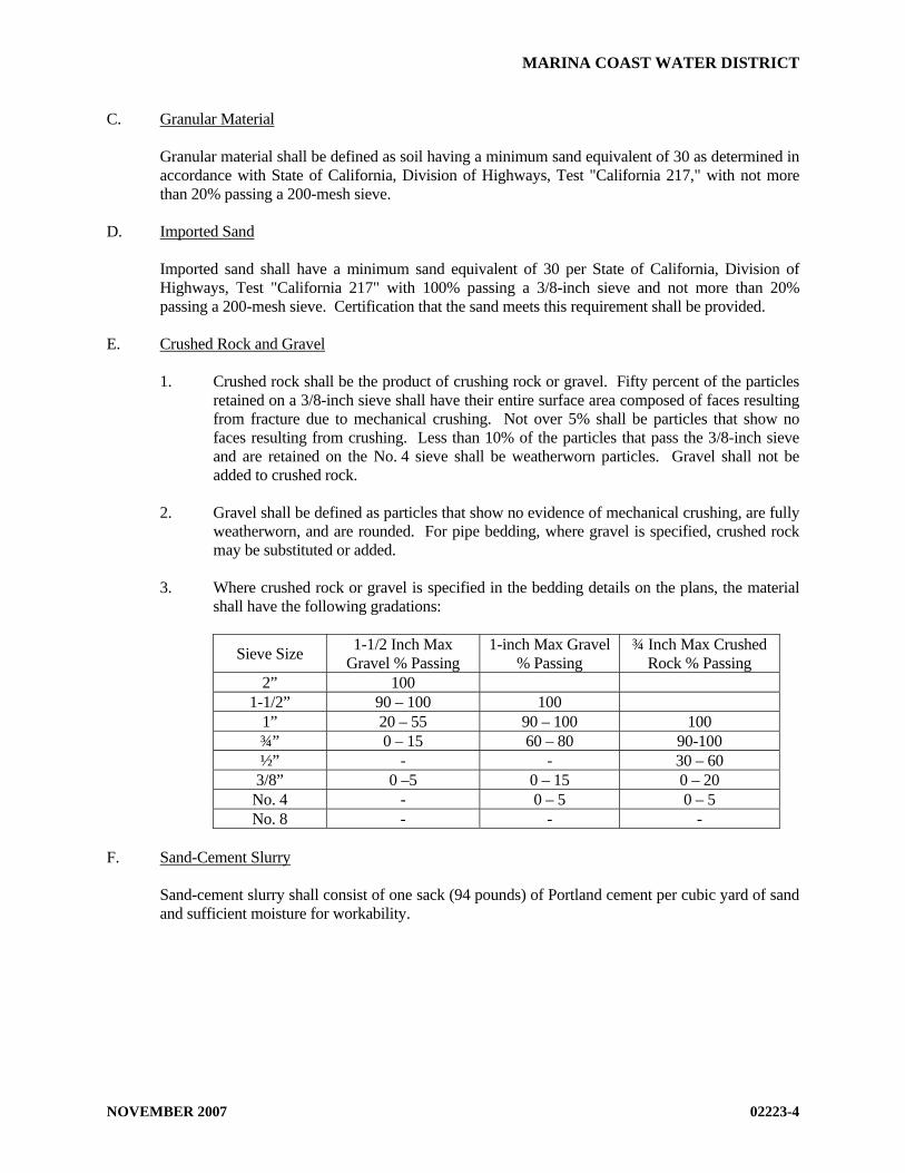
C. Granular Material Granular material shall be defined as soil having a minimum sand equivalent of 30 as determined in
accordance with State of California, Division of Highways, Test "California 217," with not more than 20% passing a 200-mesh sieve.
D. Imported Sand Imported sand shall have a minimum sand equivalent of 30 per State of California, Division of
Highways, Test "California 217" with 100% passing a 3/8-inch sieve and not more than 20% passing a 200-mesh sieve. Certification that the sand meets this requirement shall be provided.
E. Crushed Rock and Gravel 1. Crushed rock shall be the product of crushing rock or gravel. Fifty percent of the particles
retained on a 3/8-inch sieve shall have their entire surface area composed of faces resulting from fracture due to mechanical crushing. Not over 5% shall be particles that show no faces resulting from crushing. Less than 10% of the particles that pass the 3/8-inch sieve and are retained on the No. 4 sieve shall be weatherworn particles. Gravel shall not be added to crushed rock.
2. Gravel shall be defined as particles that show no evidence of mechanical crushing, are fully
weatherworn, and are rounded. For pipe bedding, where gravel is specified, crushed rock may be substituted or added.
3. Where crushed rock or gravel is specified in the bedding details on the plans, the material
shall have the following gradations:
Sieve Size 1-1/2 Inch Max Gravel % Passing
1-inch Max Gravel % Passing
¾ Inch Max Crushed Rock % Passing
2” 100 1-1/2” 90 – 100 100
1” 20 – 55 90 – 100 100 ¾” 0 – 15 60 – 80 90-100 ½” - - 30 – 60
3/8” 0 –5 0 – 15 0 – 20 No. 4 - 0 – 5 0 – 5 No. 8 - - -
F. Sand-Cement Slurry Sand-cement slurry shall consist of one sack (94 pounds) of Portland cement per cubic yard of sand
and sufficient moisture for workability.

MARINA COAST WATER DISTRICT
NOVEMBER 2007 02223-5
PART 3 - EXECUTION A. Compaction Requirements 1. The developer will engage the services of a qualified soils engineering firm to determine
the relative compaction of the trench backfill. On capital projects, the District will engage the services of a qualified soils engineering firm to determine the relative compaction of the trench backfill.
2. If the backfill fails to meet the specified relative compaction requirements, the contractor
shall rework the backfill until the requirements are met. The contractor shall make all necessary excavations for density tests as directed by the District representative. The compaction requirements of the city having jurisdiction or Caltrans shall prevail in all public roads. The developer or contractor will be responsible for the cost of all additional compaction tests in the reworked areas.
3. Compaction tests shall be performed at random depths and at 200-foot intervals and as
directed by the District representative. 4. Unless otherwise shown on the drawings or otherwise described in the specifications for the
particular type of pipe installed, relative compaction in pipe trenches shall be as described below:
a. Pipe zone and pipe base: 95% relative compaction
b. Trench zone not beneath paving: 95% relative compaction c. Trench zone to street zone in paved areas: 95% relative compaction d. Street zone in paved areas: per agency requirements or 95% relative compaction.
The most stringent agency requirements shall prevail
e. Rock refill material for foundation stabilization: 90% relative density f. Rock refill for over excavation: 90% relative density B. Material Replacement Removal and replacement of any trench and backfill material which does not meet the
specifications shall be the contractor's responsibility. C. Clearing and Grubbing 1. Areas where work is to be performed shall be cleared of all trees, shrubs, rubbish, and other
objectionable material of any kind which, if left in place, would interfere with the proper performance or completion of the contemplated work, would impair its subsequent use, or would form obstructions therein.
2. Organic material from clearing and grubbing operations will not be incorporated in the
trench backfill.

MARINA COAST WATER DISTRICT
NOVEMBER 2007 02223-6
3. Organic material from clearing and grubbing operations will be disposed of at a proper waste disposal facility.
D. Sidewalk, Pavement, and Curb Removal 1. Saw cut bituminous or concrete pavements regardless of their thickness, and curbs and
sidewalks prior to excavation for the structure in accordance with the requirements of the city, or agency having jurisdiction. Curbs and sidewalks, that are damaged in the course of construction, are to be cut and removed from joint to joint.
2. Haul removed pavement and concrete materials from the site, to a proper disposal facility.
These materials are not permitted for use as trench backfill. If the material to be removed exceeds 50 cubic yards, the contractor shall obtain a haul route permit from the city(s) having jurisdiction.
E. Trenching and Tunneling 1. Excavation for pipe, fittings, and appurtenances shall be open trench to the depth and in the
direction necessary for the proper installation of the facilities as shown on the plans. 2. Trench banks shall be kept as near to vertical as possible and shall be properly braced and
sheeted. 3. Tunneling will not be permitted. 4. The use of a jack and bore or hydraulic ram may be employed. F. Bracing
1. The contractor's design and installation of bracing and shoring shall be consistent with the rules, orders, and regulations of the State of California Construction Safety Orders.
2. Excavations shall be so braced, sheeted, and supported that they will be safe such that the
walls of the excavation will not slide or settle and all existing improvements of any kind, either on public or private property, will be fully protected from damage.
3. The sheeting, shoring, and bracing shall be arranged so as not to place any stress on
portions of the completed work until the general construction thereof has proceeded far enough to provide ample strength.
4. Care shall be exercised in the drawing or removal of sheeting, shoring, bracing, and
timbering to prevent the caving or collapse of the excavation faces being supported. G. Trench Widths 1. Excavation and trenching shall be true to line so that a clear space of not more than 8 inches
or less than 6 inches in width is provided on each side of the largest outside diameter of the pipe in place measured at a point 12 inches above the top of the pipe. For the purpose of this article, the largest outside diameter shall be the outside diameter of the bell on bell and spigot pipe or the pipe collar.

MARINA COAST WATER DISTRICT
NOVEMBER 2007 02223-7
2. Where the sewer trench width, measured at a point 12 inches above the top of the bell of the pipe, is wider than the maximum set forth above, the trench area around the pipe shall be backfilled with crushed rock, Class B concrete, or slurry to form a cradle for the pipe at the discretion of the District representative.
H. Length of Open Trench The maximum allowable length of open trench shall be 600 feet, or the distance necessary to
accommodate the amount of pipe installed in a single day, whichever is less. Within developed areas, the length of open trench may be restricted as determined by the encroachment permit from the city or the agency having jurisdiction.
I. Grade 1. Excavate the trench to the lines and grades shown on the drawings with allowance for pipe
thickness and for pipe base or special bedding. 2. The trench bottom shall be graded to provide a smooth, firm, and stable foundation that is
free from rocks and other obstructions and shall be at a reasonably uniform grade. J. Correction of Over Excavation 1. Where excavation is inadvertently carried below the design trench depth, suitable provision
shall be made by the contractor to adjust the excavation, as directed by the District representative, to meet requirements incurred by the deeper excavation.
2. Over excavations shall be corrected by backfilling with approved bedding material, graded
crushed rock or gravel and shall be compacted to provide a firm and unyielding subgrade or foundation, as directed by the District representative.
K. De-watering 1. The contractor shall provide and maintain at all times during construction ample means and
devices with which to promptly remove and properly dispose of all water from any source entering the excavations or other parts of the work. De-watering shall be done by methods that will ensure a dry excavation and preservation of the final lines and grades of the bottoms of excavations. De-watering methods may include well points, sump points, suitable rock or gravel placed below the required bedding for drainage and pumping, temporary pipelines, and other means, all subject to the approval of the District representative. Water shall be discharged in accordance with the requirements of the project’s NPDES permit.
2. In no event shall the sewer system be used as drains for de-watering the construction
trenches. 3. De-watering shall commence when groundwater is first encountered and shall be
continuous until such times as water can be allowed to rise. No concrete shall be poured in water, nor shall water be allowed to rise around the concrete or mortar until it has set at least eight hours.

MARINA COAST WATER DISTRICT
NOVEMBER 2007 02223-8
L. Foundation Stabilization 1. Whenever the trench bottom does not afford a sufficiently solid and stable base to support
the pipe or appurtenances, the contractor shall excavate to a depth below the design trench bottom, as directed by the District representative, and the trench bottom shall be backfilled with 3/4-inch rock and compacted to provide uniform support and a firm foundation.
2. Where rock is encountered, it shall be removed to a depth at least 6 inches below grade and
the trench shall be backfilled with 3/4-inch crushed rock to provide a compacted foundation cushion.
3. If excessively wet, soft, spongy, unstable, or similarly unsuitable material is encountered at
the surface upon which the bedding material is to be placed, the unsuitable material shall removed to a depth as determined in the field by the District representative and replaced by crushed rock.
M. Excavated Material 1. All excavated material shall not be stockpiled in a manner that will create an unsafe work
area or obstruct sidewalks or driveways. Gutters shall be kept clear or other satisfactory measures shall be taken to maintain street or other drainage.
2. In confined work areas, the contractor may be required to stockpile the excavated material
off-site, as determined by the project permits. N. Placing Pipe Bedding 1. Place the thickness of pipe bedding material over the full width of trench necessary to
produce the required bedding thickness when the material is compacted to the specified relative density. Grade the top of the pipe bedding ahead of the pipe to provide firm, uniform support along the full length of pipe.
2. Excavate bell holes at each joint to permit assembly and inspection of the entire joint. O. Placing Mounds to Support Pipe (DIP Only) 1. As an alternate to placing continuous imported sand pipe bedding material, the ductile iron
pipe may be supported on mounds of imported sand. 2. The mounds shall be of imported sand and extend the full trench width. The mounds shall
provide a minimum of 6 inches of contact with the pipe. 3. The pipe shall be supported to maintain its design line and grade. 4. The mounds shall be located 2½ feet from the bell/spigot of the pipe. P. Backfilling within Pipe Zone 1. Backfill per the detailed piping specification for the particular type of pipe and per the
following.
MARINA COAST WATER DISTRICT
NOVEMBER 2007 02223-9
2. After pipe has been installed in the trench, place pipe zone material simultaneously on both sides of the pipe, keeping the level of backfill the same on each side. Carefully place the material around the pipe so that the pipe barrel is completely supported and that no voids or uncompacted areas are left beneath the pipe. Use particular care in placing material on the underside of the pipe to prevent lateral movement during subsequent backfilling.
3. Compact material placed within 12 inches of the outer surface of the pipe by hand tamping
only. Q. Backfill within Trench Zone 1. Compact per the detailed piping specification for the particular type of pipe and per the
following.
2. Push the backfill material carefully onto the backfill previously placed in the pipe zone. Do not permit free fall of the material until at least 2 feet of cover is provided over the top of the pipe. Do not drop sharp, heavy pieces of material directly onto the pipe or the tamped material around the pipe.
3. The remaining portion of the trench to the street zone or ground surface, as the case may
be, shall be backfilled, compacted and/or consolidated by approved methods to obtain the specified relative compaction.
a. Compaction using vibratory equipment, tamping rollers, pneumatic tire rollers, or
other mechanical tampers shall be done with the type and size of equipment necessary to accomplish the work. The backfill shall be placed in horizontal layers of such depths as are considered proper for the type of compacting equipment being used in relation to the backfill material being placed. Each layer shall be evenly spread, properly moistened, and compacted to the specified relative density. The contractor shall repair or replace any pipe, fittings, manholes, or structures as directed by the District representative damaged by the contractor's operations.
b. Consolidation of backfill performed by flooding, poling, or jetting shall obtain a
relative compaction of the backfill material at least equal to that specified. When flooding, poling, or jetting methods are used, material for use as backfill shall be placed and consolidated in layers not exceeding 3-feet thick. Flooding, poling, or jetting methods shall be supplemented by the use of vibratory or other compaction equipment when necessary to obtain the required relative compaction. Care shall be taken in all consolidating operations to prevent the movement or floating of the pipe. Consolidation methods shall not be used where the backfill material is not sufficiently granular to be self-draining during and after consolidation, or where foundation materials may be softened or otherwise damaged by the quantities of water applied. The contractor shall rectify any misalignment of the pipe because of consolidation operations as directed by the District representative.
R. Backfill within Street Zone 1. The street zone within roadbed areas shall be compacted using approved hand, pneumatic,
or mechanical type tampers to obtain the required relative compaction.

MARINA COAST WATER DISTRICT
NOVEMBER 2007 02223-10
2. All work shall be done in accordance with the requirements and to the satisfaction of the city or the agency having jurisdiction.
3. Flooding and jetting will not be permitted in this Zone. S. Sidewalk, Pavement, and Curb Replacement Replace bituminous and concrete pavement, curbs, and sidewalks damaged or removed during
construction in accordance with the requirements of the city or the agency having jurisdiction.
T. Slope Protection
1. Where cutoff walls or concrete anchors are required, they shall be in accordance with MCWD Standard Plan S-10, with a minimum thickness of 12 inches. The wall shall extend at least 12 inches to undisturbed material on each side of the trench as excavated. Cemented rubble and concrete surface slope protection shall be a minimum of 4-inches thick.
2. Wall or anchors shall be placed with a minimum horizontal spacing of:
a. Not over 36 feet center to center on grades 25% to 35%
b. Not over 24 feet center to center on grades 35% to 50%
c. Not over 16 feet center to center on grades 50% and over
3. Material used for construction of cutoff walls or concrete anchors shall consist of cast-in-
place reinforced concrete or reinforced hollow unit masonry. When reinforced hollow unit masonry is used, all cells in the block shall be filled solidly with grout. A No. 4 reinforcing bar shall be placed in vertically in each row of cells and No. 9-gage wall mesh shall be placed in each horizontal joint. In addition, a bond beam shall be placed at the top with two No. 4 bars.
Where cutoff walls or concrete anchors are constructed of reinforced concrete, they shall have No. 4 reinforcing bars placed at 6-inches on center each way in the center of the wall. The bars shall extend full length and height of the wall.
END OF SECTION

MARINA COAST WATER DISTRICT
AUGUST 2005 02315-1
STANDARD SPECIFICATIONS
SECTION 02315
JACKED CASING PART 1 - GENERAL A. Description Tunneling method by jacked casing, directional drilling, or a tunnel boring machine, for highway,
railroad, creek, and culvert crossings and other shallow depth tunnels, and carrier pipe installation. B. Related Work Specified Elsewhere All related work specified elsewhere, or in other codes or standards, will be as last revised, unless a
specific date of issuance is called out in opposition to later revision date(s). Other sections of the technical specifications, not referenced below, shall also apply to the extent
required for proper performance of this work. 1. Trenching, Backfilling, and Compacting: 02223 2. Concrete: 03300 3. Hydrostatic Testing of Pressure Pipeline: 15042 C. Permits All work shall conform to the specifications and requirements of the State of California Department
of Transportation, the County, the city having jurisdiction, or and other agencies involved. The contractor shall keep a copy of all the required permits in the job site and comply with all the terms and conditions of said permits.
D. Alternative Methods The contractor may present an alternative detailed proposal in lieu of the methods and materials
specified herein to jack or bore casing pipe at the locations shown on the plans. Any such proposal shall be presented to the District representative a minimum of 28 calendar days in advance of the work to allow adequate time for checking, and must be in accordance with all the conditions set forth in the permits.
E. Safety The contractor shall obtain from the Division of Industrial Safety a classification for each bore
exceeding 30-inches in diameter. It shall be the contractor’s responsibility to see that the work is done in conformance with the state requirements. It shall also be the contractor’s responsibility to call the required safety meeting with representatives from the State Division of Industrial Safety prior to beginning the construction of each bore.
MARINA COAST WATER DISTRICT
AUGUST 2005 02315-2
F. Scheduling If the pipeline is not installed within the casing as a continuous operation following completion of
jacking, then bulkhead the portals and backfill the approach trenches and later reopen them for pipe installation.
G. Line and Grade
1. The contractor’s attention is called to the fact that the casing pipe must be installed to the tolerances listed on the plans so as to permit the construction of the carrier pipe to the lines and grades shown on the plans.
2. It is the contractor’s responsibility to choose a size of casing at or above the minimum
specified, to insure that the jacking is done with a high degree of accuracy to permit installation of the carrier pipe to the grades shown on the plans.
H. Design
It is the contractor’s responsibility to retain an engineer to design a casing that meets or exceeds the minimum specified, and to insure that the casing is compatible with the jacking machine, and the boring head used. Design must be submitted to and approved by District Engineer
PART 2 – MATERIALS A. Steel Casing
1. New steel casing pipe, unless otherwise approved by the District representative, shall be butt-welded sheets conforming to ASTM A 245, commercial grade or of plate conforming to ASTM A 283, Grade C, or ASTM A-36.
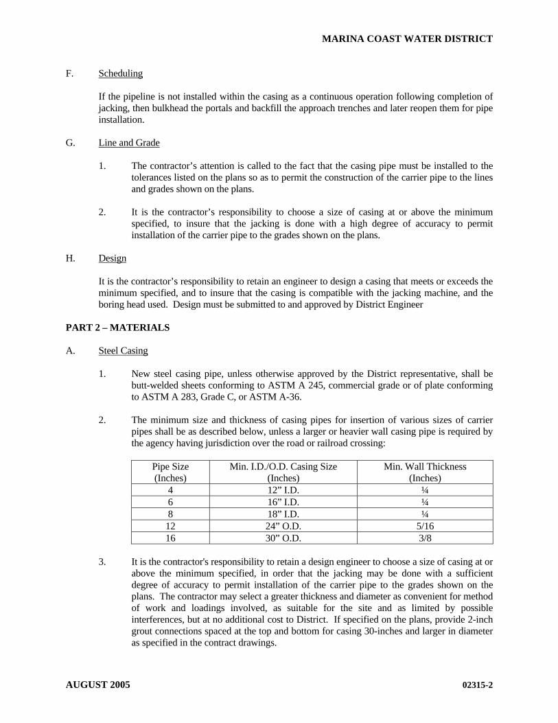
2. The minimum size and thickness of casing pipes for insertion of various sizes of carrier
pipes shall be as described below, unless a larger or heavier wall casing pipe is required by the agency having jurisdiction over the road or railroad crossing:
Pipe Size (Inches)
Min. I.D./O.D. Casing Size (Inches)
Min. Wall Thickness (Inches)
4 12” I.D. ¼ 6 16” I.D. ¼ 8 18” I.D. ¼ 12 24” O.D. 5/16 16 30” O.D. 3/8
3. It is the contractor's responsibility to retain a design engineer to choose a size of casing at or
above the minimum specified, in order that the jacking may be done with a sufficient degree of accuracy to permit installation of the carrier pipe to the grades shown on the plans. The contractor may select a greater thickness and diameter as convenient for method of work and loadings involved, as suitable for the site and as limited by possible interferences, but at no additional cost to District. If specified on the plans, provide 2-inch grout connections spaced at the top and bottom for casing 30-inches and larger in diameter as specified in the contract drawings.

MARINA COAST WATER DISTRICT
AUGUST 2005 02315-3
Casing sections shall be joined by full-circumference butt-welding in the field. Prepare ends of casings for welding by providing ¼-inch X 45 degree chamfer on outside edges.
B. Grout 1. Grout shall consist of Portland cement and water or of Portland cement, sand, and water;
and all grout mixtures shall contain 2% of bentonite by weight of the cement. 2. Portland cement, water and sand shall conform to the applicable requirements of the
concrete section (Section 03300), except that sand to be used shall be of such fineness that 100% will pass a standard 8-mesh sieve and at least 45%, by weight, will pass a standard 40-mesh sieve.
3. Bentonite shall be a commercially processed powdered bentonite, Wyoming type, such as
Imacco-gel, Black Hills or approved equal. C. Stainless Steel Spacers Casing spaces shall be bolt on style with a two-piece shell made of 304 stainless steel of a minimum
14-gauge thickness. Each shell section shall have bolt flanges formed with fins for added strength. Each connection flange shall have a minimum of three 5/16 inch 304 stainless bolts. The shell shall be lined with a ribbed PVC extrusion with a retaining section that overlaps the edge of the shell and prevents slippage. Bearing surfaces (runners) made from UHMW polymer with a static coefficient of friction of 0.11 - 0.13 shall be attached to support structures (risers). The runners shall be attached mechanically by 304 stainless fasteners that are inserted through the punched riser section and welded for strength. Risers shall be made of 304 stainless of a minimum 14 gauges. All risers over 2 inches in height shall be reinforced. Risers shall be welded to the shell. All metal surfaces shall be fully passivated. Casing spacers shall be as specified on the plans.
D. End Seal End seals shall be virgin Buna-s or Buna-gis (styrene-butadiene) rubber with 316 stainless steel
bands. End seal kits shall include a bottle of bonding cement. End seals shall be “Link Seal” or “PSI Model C” end seals.
E. Sacrificial Anodes for Cathodic Protection
1. Anodes for cathodic protection of steel casing shall be sized for the amount of casing
surface area and shall be a minimum of 2-inch by 2-inch by 60-inch high purity zinc anodes, bagged in calcium sulfate and bentonite backfill.
2. The anodes shall be cadwelded to the casing with No. 6 high molecular weight polyethylene (HMWPE) -covered, stranded copper lead wire.
PART 3 - EXECUTION A. Sectional Shield or Jacking Head 1. Fit a sectional shield or steel jacking head to the leading section of the casing. The shield
or head shall extend around the outer surface of the upper two-thirds of the casing and

MARINA COAST WATER DISTRICT
AUGUST 2005 02315-4
project at least 18 inches beyond the driving end of the casing. It shall not protrude more than ½ inch beyond the outer casing surface.
2. Anchor the head to prevent any wobble or alignment variation during the jacking operation. 3. To avoid loss of ground outside the casing, carry out excavation entirely within the jacking
head and not in advance of the head. In general, excavated material shall be removed from the casing as jacking progresses and no accumulation of excavated material within the casing will be permitted.
4. A jacking band to reinforce the end of the pipe receiving the jacking thrust will be required. B. Jacking Pit 1. The approach trench for jacking or boring operations shall be adequately shored to
safeguard existing substructures and surface improvements and to ensure against ground movement in the vicinity of the casing portal.
2. Place in the approach trench of jacking pit and firmly bed on the required line and grade
heavy guide timbers, structural steel, or concrete cradle of sufficient length to provide accurate control of jacking alignment. Provide adequate space to insert the casing lengths to be jacked. Anchor the timbers and structural steel sections to ensure action of the jacks in line with the axis of the casing. Place a timber or structural steel bearing block between the jacks and the end of the casing to provide uniform bearing upon the casing end evenly distribute the jacking pressure.
3. Provide bracing, shoring and ladders necessary to meet trench safety requirements.
Confined space testing may be required as conditions dictate. C. Control of Alignment and Grade Control the application of jacking pressure and excavation of material ahead of the advancing
casing to prevent it from becoming friction bound or deviating from required line and grade, as detailed in the plans. Do not encroach upon the minimum annular space detailed. Restrict the excavation of material to the least clearance necessary to prevent binding in order to avoid settlement or possible damage to overlying structures or utilities.
D. Grouting Immediately after completion of the jacking or boring operation, lean grout shall be injected
through the grout connections of casings 30-inches and larger in a manner that will completely fill all voids outside the casing pipe resulting from the jacking or boring operation. The lean grout shall consist of one part Portland cement, four parts sand, and sufficient water to produce a workable mixture. Grout pressure is to be controlled so as to avoid deformation of the casing and/or avoid movement of the surrounding ground. Sand for grout to be placed outside the casing shall be of such fineness that 100% will pass a No. 8 sieve and not less than 35% will pass a No. 50 sieve. After completion of grouting, the grout connections shall be closed with cast-iron threaded plugs.
E. Installation of Carrier Pipe 1. The carrier pipe shall be pushed into the casing pipe using stainless steel casing spacers,
which shall be sized to restrain the pipe from moving within the casing. If the casing has

MARINA COAST WATER DISTRICT
AUGUST 2005 02315-5
deviated from the design line and grade; specifically fabricated casing spacers may be used to correct the problem.
2. The casing pipe spacers shall be place so as to support all of the carrier pipes within two feet or less of the end of the casing pipe. Unless noted otherwise in the plans, casing pipe spacers shall be placed at a minimum of one at the bell end and one at the center of each length of pipe.
3. Before sealing the carrier pipe ends, the carrier pipe shall pass an initial pressure test per
Section 15042 or leakage test per Section 15043. F. Sand Backfill for Annular Space in Jacked Casing
1. Use air-blown sand to fill the annular space between the casing and the carrier pipe unless otherwise required by the agency having jurisdiction over the road or railroad crossing.
2. Furnish the necessary sand, air compressor, hoses, pressure gauges, valves, and fittings for
the filling operation.
3. Air blown sand shall conform to the requirements for imported sand in Section 02223. Sand shall be free of lumps when put into the hopper. Sand shall be of a consistency to flow unimpeded and completely fill all voids.
4. Place a bulkhead for retaining the sand in the annular space between the casing and the
carrier pipe at each end of the jacked casing. At the start of the sand fill operation, extend the sand discharge pipe from the placing equipment, through the inside of the casing, and to the bulkhead at the remote end of the casing. The method used to place the sand shall be such to ensure complete filling of the annular space. During placement, position the sand discharge pipe so that its discharge end shall be kept well buried in the sand at all times after the sand has been built up over the crown of the pipe at the remote end of the section being filled. Install a riser pipe suitable for a vent in the casing adjacent to the bulkhead at the near end of the casing. Plug the vent pipe with grout upon completion of sand filling.
G. Sealing Ends of the Casing The ends of the casing pipe shall be sealed with a rubber shroud, held in place with stainless steel
straps, as shown on MCWD Standard Plan W-19 or S-11. The diameters and lengths of the end seals shall be sized to fit each casing pipe and carrier pipe to assure a positive barrier to backfill debris and seepage.
H. Installing Sacrificial Anodes for Cathodic Protection
1. The size and number of anodes is determined by the soils resistivity, the amount of metal surface area and the desired service life of the anode and shall be determined by the Engineer. A minimum of one sacrificial anode shall be buried at each end of the casing.
2. Lead wire shall be cadwelded to the casing in accordance with Erico Engineering
specification No. A160-A05. 3. Cover each weld with Royston “Handy Cap.” 4. Each anode shall be saturated with 20 gallons of water, prior to backfill of the trench.

MARINA COAST WATER DISTRICT
AUGUST 2005 02315-6
I. Closing the Jacking Pit After jacking equipment and muck from the tunnel have been removed from the approach trench of
jacking pit, prepare the bottom of the jacking pit as a pipe foundation. Remove all loose and disturbed material below pipe grade to undisturbed earth and recompact the material in accordance with Section 02223.
END OF SECTION
MARINA COAST WATER DISTRICT
NOVEMBER 2007 02701-1
STANDARD SPECIFICATIONS
SECTION 02701
INSTALLATION OF GRAVITY SEWER PIPELINES PART 1 - GENERAL A. Description This section describes the installation of gravity sewer pipelines fabricated of polyvinyl chloride
(PVC). B. Related Work Described Elsewhere 1. Trenching, Backfilling and Compacting: 02223 2. Jacked Casing: 02315 3. PVC Gravity Sewer Pipe: 02715 4. Concrete: 03300 5. Precast Concrete Manholes and Manhole Bases: 03461 6. Leakage and Infiltration Testing: 15043 7. Ductile Iron Pipe and Fittings: 15056 8. Underground Facilities Identification 15151 C. Submittals
1. An installation schedule (tabulated layout) shall be submitted which includes:
a. Order of installation and closures b. Pipe centerline station and elevation at each change of grade and alignment c. Locations of manholes PART 2 - MATERIALS A. Installation Material Refer to Section 02715, PVC Gravity Sewer Pipe for material requirements.

MARINA COAST WATER DISTRICT
NOVEMBER 2007 02701-2
B. Piping Schedule Unless noted otherwise on the plans or in the specifications, pipe shall be furnished in accordance
with the following materials schedule.
DIAMETER GRAVITY SEWER 2-inch and smaller -- 4-inch through 15-inch PVC SDR-35 15-inch through 24-inch PVC PS 46 27-inch through 36-inch PVC PS 46 or DIP with polyethylene lining, as
indicated on plans
Notes: PVC gravity sewer pipe per Section 02715. PVC SDR-26 or PS 115, where indicated, per Section 02715. DIP - Ductile iron pipe per Section 15056.
PART 3 - EXECUTION A. Delivery and Temporary Storage of Pipe at Site
1. Onsite Storage Limitation: Onsite pipe storage shall be limited to a maximum of one week, unless exception is approved by District.
2. Care of Pipe: At times when the pipe laying is not in progress, the open end of the pipe
shall be closed with a tight-fitting cap or plug to prevent the entrance of foreign matter into the pipe. These provisions shall apply during the noon hours as well as overnight. In no event shall the sewers be used as drains for removing water which has infiltrated into the construction trenches.
B. Handling of Pipe
1. Moving Pipe: Pipes shall be lifted with handling beams or wide belt slings as recommended by the pipe manufacturer. Cable slings shall not be used. Pipe shall be handled in a manner to avoid damage to the pipe. Pipe shall not be dropped or dumped from trucks or into trenches under any circumstances.
2. Inspection Pipe: The pipe and accessories shall be inspected for defects prior to lowering
into the trench. Any defective, damaged or unsound pipe shall be repaired or replaced. All foreign matter or dirt shall be removed from the interior of the pipe before lowering into position in the trench.
C. Placement of Pipe in Trench 1. General: All pipe shall be laid without a break, upgrade from structure to structure, with
the bell ends of the pipe upgrade. Pipe shall be laid to the line and grade given so as to form a close concentric joint with the adjoining pipe and prevent sudden offsets of the flow line.

MARINA COAST WATER DISTRICT
NOVEMBER 2007 02701-3
2. Trench Excavation: Dewatering, excavation, shoring, sheeting, bracing, backfill material placement, material compaction, compaction testing, and pipe laying requirements and limitations shall be in accordance with Section 02223, Trenching, Backfilling, and Compacting.
3. Pipe Bedding Thickness: Unless shown otherwise on the drawings, pipe bedding
material shall be 3/4-inch crushed rock for PVC pipe specified in Section 02223, Trenching, Backfilling, and Compacting or compacted backfill material per Section 02223.
4. Subgrade at Joints: At each joint in the pipe, the pipe subgrade shall be recessed in firm
bedding material so as to relieve the bell of the pipe of all load and to ensure continuous bearing along the pipe barrel.
5. Cleaning: The interior of the sewer pipe shall be cleaned of all dirt and superfluous
materials as the work progresses. 6. Joints: The mating surfaces of the pipe to be joined shall be wiped clean of all dirt and
foreign matter and a lubricant applied that is approved by the pipe manufacturer. Then, with the surfaces properly lubricated, the spigot end of the pipe shall be positioned inside the bell and the joint shoved home.
For larger diameter pipe where a lever attachment is required, the necessary precautions
shall be taken to insure an undamaged pipe installation. 7. Pipe Alignment: Unless specified otherwise, pipeline line and grade shall be as shown on
the plans. Grade shall be measured along the pipe invert. 8. PVC Pipe Curvature: Construction of curved reaches of PVC pipe shall not be
accomplished by deflecting joints or by beveling pipe ends. Bending of PVC pipe to achieve vertical or horizontal curves without using deflection fittings shall be limited as follows:
Diameter (Inches) Minimum Radius (Feet)
6 210 8 280
10 350 12 420
9. Laterals: PVC wyes and other types of branches shall be furnished and installed along
with the PVC sewer. Wyes sized as specified on the plans shall be installed for all sewer house connections and for future sewer house connections as shown on the plans. The longitudinal barrel of branch fittings, to be placed in line and grade with the sewer mains, shall be of the same diameter, quality, and type as specified herein for sewer installations. Earthwork and bedding for branches and shall conform to the applicable provisions set forth in the specification for each pipe material. The branch of wye fittings shall be inclined upward at an angle not greater than 45 degrees from a horizontal line for sewer lines up to ten feet deep, and no more than 60 degrees for sewers deeper than 10 feet. No wye for sewer house connection branch shall be placed closer than 5 feet downstream of
MARINA COAST WATER DISTRICT
NOVEMBER 2007 02701-4
the centerline of any structure. The contractor shall place a support of graded crushed rock or imported sand under every wye branch when installed. The support shall be placed in accordance with the detail on the plans or as specified in Section 02223, Trenching, Backfilling, and Compacting.
10. Backfill: Backfill shall be placed and compacted in accordance with the requirements of
Section 02223, Trenching, Backfilling and Compacting, and as shown on MCWD Standard Plan S-5. Backfill within the pipe zone shall be clean native sand for PVC pipe.
D. Manholes and Manhole Bases Precast concrete manholes and manhole bases shall be constructed in accordance with Section
03461, Precast Concrete Manholes and Manhole Bases, as shown in the plans or on MCWD Standard Plan Nos. S-1, S-2, and S-3.
E. House Laterals 1. Locations: House laterals and wye branch fittings of the size indicated on the plans shall
be installed at the locations shown on the plans or at the location furnished by the District representative.
2. Plugged Branches: All branch fittings that are to be left unconnected shall be plugged. 3. Fittings: House laterals shall be joined to wye branch fittings at the sanitary sewer main
as set forth above by eighth bends. All eighth bends and sixteenth bends are a part of house lateral sewerline.
4. Alignment: Where possible, all house laterals shall run perpendicular to the sewer main
from the main to the property line, and all house laterals shall be bedded the same as the sewer main into which they connect.
5. Plugged House Laterals: All house laterals shall be plugged with an approved stopper in
the socket of the last joint of each house lateral so that it will withstand the internal pressure during the test for leakage, per Section 15013, but also in such a manner that it may be removed without injury to the socket.
6. Marking: The contractor shall mark the location of each house lateral at its upper end by
chiseling a letter "S" 1-1/2-inches high on the face of the curb.
7. Chimney Connections: Chimney connections are not allowed.
8. Mainline Testing: The mainline sewer shall have passed final testing per Section 15043 before the laterals may be connected to the main.
F. Cleanouts
1. Limitations: Sewer clean-outs of the size indicated on the plans shall be installed at the locations shown on the plans or at the location furnished by the District representative. The use of cleanouts shall be limited to the following instances unless approved otherwise by the District engineer.

MARINA COAST WATER DISTRICT
NOVEMBER 2007 02701-5
a. Short sections of sewer main, less than 250-feet that will be extended.
b. All commercial and industrial sewer lateral installations at the property line.
c. Between manholes, if there is a reverse curve in the sewer main, to facilitate cleaning of the main line.
d. Special instances such as on a sewer lateral to a single family residential lot
where the dwelling unit is set back more than 100-feet from the property line, where there is a large slope up to the building pad from the property line, and a grade change in the lateral is necessary, or where the sewer lateral enters the rear of the lot from a public right-of-way.
e. On a lateral where the overflow level of the lowest wastewater fixture in the
building is below the rim elevation of the uphill sewer manhole on the main line. In this situation the rim elevation of the cleanout installed at the property line shall be at least 6-inches below the overflow elevation of the lowest wastewater fixture on the lateral. A backflow prevention device is required on the lateral per Section 4.11 of the District’s Code.
2. Size: Cleanouts shall be PVC pipe and shall be the same size as the line on which they
are installed. Cleanouts shall be constructed as shown on the MCWD Standard Plan S-8. G. Saddle Connections 1. General: All saddle connections of new laterals into existing sewer lines shall be made
with a wye saddle. 2. Scoring and Tapping: The sewerline to be saddled shall be scored to the approximate
shape of wye or tee and shall be cut with a hole cutter. The tap holes shall be cleanly machined and may be further worked by hand to provide a true and neat opening for the collar wye or tee saddle. Pipe damaged during this operation shall be repaired or replaced. The District representative shall be the sole judge as to the method of repair or replacement.
3. Securement: The collar wye shall be secured to the sewer main with a catalytic epoxy
resin. The saddle shall be tied to the main with wire of sufficient strength that no movement will occur during the setting of the epoxy resin.
4. Encasement: After the connection has set sufficiently long for the epoxy resin to cure,
the District will inspect the connection and, if satisfactory, the contractor shall encase the fitting with Class B Portland cement concrete to the limits indicated on MCWD Standard Plan S-97.
5. Cleaning: The saddling operation shall be carried out in a workmanlike manner. Chips,
dirt, epoxy mortar, and concrete shall be kept out of the sewer line being saddled. If directed by the District representative, the reach of sewer main saddled shall be flushed and cleaned using a hydrocleaner or vacuum truck.

MARINA COAST WATER DISTRICT
NOVEMBER 2007 02701-6
6. Alternative Connection: In lieu of a saddle connection, a wye connection may be made by cutting the sewer and installing a wye.
H. Installation Within Jacked Casing 1. General: The sewer pipe shall be installed within the casing pipe to the lines and grades
shown on the plans and in accordance with Section 02315, Jacked Casing. 2. Pipe Support: The carrier pipe shall be supported on cradles such as “PSI” spacers,
Model C8G-2, or approved equal before backfilling, in such a manner as to relieve the pipe bells from any bearing loads.
3. Fill Within the Casing: The annular space between the casing and the carrier pipe shall
be backfilled per Section 02315, Jacked Casing. 4. Testing: Before backfilling as specified above, the sewer carrier pipe shall pass an initial
test for leakage as provided in Section 15043, Leakage and Infiltration Testing. I. Pipe Anchorage (For Pipelines Having a Diameter of 10-Inches or Less) 1. General: Concrete slope anchors shall be installed where shown on the plans in
accordance with Section 03300 and MCWD Standard Plan S-10, wherever the profile of the ground surface above the sewer main exceeds 20 percent, and where no pavement or other surfacing is to be laid over the facility.
2. Dimensions: Anchors shall be a minimum of 12-inches thick and shall extend at least 12-
inches into undisturbed material on each side of the trench as excavated. 3. Slope Protection: Cemented rubble and concrete surface slope protection shall be a
minimum of 4-inches thick. 4. Spacing: Spacing between pipe anchors shall not exceed the distances shown on MCWD
Standard Plan S-10. 5. Reinforcement for Concrete Anchors: Anchors constructed of cast-in-place reinforced
concrete shall have No. 4 reinforcing bars placed at 6-inches on center each way in the center of the anchor thickness. The bars shall extend full length and height of the anchor.
6. Reinforcement for Concrete Masonry Unit Anchors: Reinforced hollow masonry units
shall have all cells filled solidly with grout. A No. 4 reinforcing bar shall be placed vertically in each row of cells and No. 9 gage wall mesh shall be placed in each horizontal joint. In addition, a bond beam shall be placed at the top with two No. 4 bars.
J. Concrete Encasement Unless shown otherwise, concrete for encasement shall be reinforced or unformed or rough
formed, and of the class as designated on the plans. Concrete shall be in accordance with Section 03300, Concrete. Concrete used for encasing, cradling, bedding, cover for pipe, or other objects shall be used as shown on the Plans, on MCWD Standard Plan S-9, or as directed by the District representative.

MARINA COAST WATER DISTRICT
NOVEMBER 2007 02701-7
K. Cleaning Before testing, each pipe shall be thoroughly cleaned from manhole to manhole with a sewer
scrubbing ball, and all debris and trash shall be removed from each manhole. L. Mandrel Test for PVC Gravity Sewers 10-inch in Diameter and Smaller Following placement and compaction of backfill for all utilities, and prior to the placement of
permanent pavement, all sewer mains shall be cleaned and mandrelled to verify that the pipeline is free from obstructions (deflections, joint offsets, lateral pipe intrusions, etc.) in accordance with Section 15043.
M. Leakage and Infiltration Test The pipe, manholes, and other appurtenances shall be tested for leakage and infiltration per
Section 15043, Leakage and Infiltration Testing. N. Closed-Circuit Television Inspection
1. General: In addition to the regular leakage and infiltration test, the entire length of all new sewer lines shall be inspected by the contractor using closed-circuit television equipment. The inspection shall be conducted after the line has been successfully tested and prior to paving. The inspection shall be conducted in the presence of the District representative. For pipe lengths designed to absolute minimum design slopes (See Section 500-2 of the Procedural Guidelines), video inspection shall provide a profile of the sewer line.
2. Responsibility: All labor and equipment necessary to conduct this inspection shall be
furnished by the contractor.
3. Notification: Requests for sewer line inspection shall be made to the District representative a minimum of two working days in advance of the requested inspection date.
4. Flushing: Each sewer section shall be flushed with water being introduced at the
upstream manhole of each section prior to video recording.
5. Stationing: The video shall show stationing corresponding to sewer stationing shown on plans for each manholes and Wye location.
6. Submittal: The videotape shall be VHS format and be submitted to the District with two
(2) of the computer printouts showing manhole numbers and stationing, wye stationing and distance between manholes prior to occupancy release for the dwelling units being served by the sewer. The tape and printout shall be labeled with the project name, tract number, street names, and contractor’s name and shall list the station of any defects, dirt, low spots, etc. in the pipe.
7. Repair of Defects: Even though the sewer line may have successfully passed the leakage
and infiltration tests, any defects or low spots in the line shall be repaired to the satisfaction of the District.

MARINA COAST WATER DISTRICT
NOVEMBER 2007 02701-8
8. Acceptance: Sewer section having standing water or defects shall be repaired by the contractor prior to District acceptance and prior to occupancy release for the dwelling units or commercial site being served by the sewer. Standing water in the system will not be allowed.
O. Final Inspection After paving has been completed and all manholes raised to grade, a final visual inspection shall
be made. The necessary labor shall be furnished to assist the District representative in making the final inspection. Additional balling may be required if the lines are dirty, even though lines were previously balled. The contractor shall furnish a responsible person or supervisor for the final inspection to remove manhole covers and to note any corrections required by the District representative in order to obtain final approval. Final District inspection shall be requested through the District representative by giving at least two day's notice.
END OF SECTION

MARINA COAST WATER DISTRICT
AUGUST 2005 02715-1
STANDARD SPECIFICATIONS
SECTION 02715
PVC GRAVITY SEWER PIPE PART 1 - GENERAL A. Description This section includes materials, testing, and installation of polyvinyl chloride (PVC) gravity
sewer pipe and fittings. B. Related Work Specified Elsewhere 1. Trenching, Backfilling and Compacting 02223 2. Jacked Casing: 02315 3. Installation of Gravity Sewer Pipelines: 02701 4. Concrete: 03300 5. Precast Concrete Manholes and Manhole Bases: 03461 6. PVC Distribution Pipe: 15064 C. Submittals 1. Provide materials list showing material of pipe and fittings with ASTM references and
grade. 2. Provide certificates of compliance with all standards referenced in this section. D. Application 1. PVC SDR 35 shall be used for gravity sewer mains up to and including 15-inch in
diameter, except as specifically called out on the project plans. 2. PVC PS 46 shall be used for gravity sewer mains from 18-inch through 24-inch in
diameter, except as specifically called out on the project plans. 3. Deeper sewer pipes and/or shallow sewer pipes under traffic crossings may be required to
be SDR 26 or PS 115, at the direction of the District Engineer. E. Sewer Force Mains PVC sewer force mains shall be constructed in accordance with the requirements for PVC
Distribution Pipe, Section 15064. F. Inverted Siphons

MARINA COAST WATER DISTRICT
AUGUST 2005 02715-2
Inverted siphons of the size indicated on the plans shall be installed at the locations shown on the
plans or at the locations approved by the District Engineer. PART 2 - MATERIALS A. Pipe and Fittings 1. ASTM Requirements: Pipe, fittings, couplings, and joints shall be in conformance with
the size, material and performance requirements of ASTM D 3034, for SDR 35 and SDR 26 pipes, 15-inch and smaller, and shall have gasketed joints. Pipe, fittings, couplings, and joints shall be in conformance with the size, material and performance requirements of ASTM F 679, for PS 46 and PS 115 pipes, 18-inch and larger, and shall have gasketed joints. Pipe shall be made of PVC plastic having a cell classification of 12454-B, 12454-C, or 13364-B as defined in ASTM D 1784. Fittings shall be made of PVC plastic having a cell classification of 12454-B, 12454-C, or 13343-C. All pipe shall be of solid wall construction with smooth interior and exterior surfaces.
2. Manufacturer’s Testing Certification: During production of the pipe, the manufacturer
shall perform the specified tests for each pipe marking. A certification by the manufacturer indicating compliance with specification requirements shall be delivered with the pipe. The certification shall include the test result data.
3. Pipe Marking: All pipe, fittings, and couplings shall be clearly marked at an interval not
to exceed 5-feet as follows: a. Nominal pipe diameter b. PVC cell classification c. Company, plant, shift, ASTM, SDR, and date designation d. Service designation or legend For fittings and couplings, the SDR designation is not required. All pipe shall have a
home mark on the spigot end to indicate proper penetration when the joint is made. 4. Additional Pipe Tests Following Delivery: When pipe is delivered to the jobsite, the
District representative may require additional testing to determine conformance with the requirements of pipe flattening, impact resistance, pipe stiffness, and extrusion quality. When testing is required, one test pipe shall be selected at random by the engineer from each 1,200 feet or fraction thereof of each size of pipe delivered to the jobsite but not less than one test pipe per lot. A lot shall be defined as pipe having the same identification marking. The length of specimen for each selected pipe shall be a minimum of 8-feet.
5. Pipe Retest: Pipe which is not installed within 120 days of the latest test shall not be used
without prior approval of the District representative.
6. Fitting and Coupling End Configurations: The socket and spigot configurations for fittings and couplings shall be compatible with those used for the pipe.

MARINA COAST WATER DISTRICT
AUGUST 2005 02715-3
7. Manufacturers: Pipe shall be as manufactured by J-M Manufacturing Ring-Tite, Vinyltech, P W Pipe, Diamond Plastics, Carlon, or approved equal. Fittings shall be as manufactured by J-M Manufacturing, GPK Products, or approved equal.
B. Gaskets for PVC Pipe 1. General: Unless otherwise specified, gaskets shall be manufactured from a synthetic
elastomer, and shall be extruded or molded and cured in such a manner as to be dense, homogeneous and of smooth surface, free of pitting, blisters, porosity, and other imperfections. The compound shall contain not less than 50 percent by volume of first-grade synthetic rubber. The remainder of the compound shall consist of pulverized fillers free of rubber substitutes, reclaimed rubber, and deleterious substances. The tolerance for any diameter measured at any cross section shall be ±1/32-inch (.8mm).
2. Gasket Material Requirements: When required by the District representative, the
contractor shall furnish test samples of gaskets from each batch used in the work. Gasket material shall meet the following requirements:
Property Value ASTM Test Method
Tensile Strength (min. psi) 2,000 D 412 Elongation at break (% min.) 350 D 412 Shore durometer, Type A (Pipe manufacturer shall select value suitable for type of joint)
40 to 65* D 2240
Compression set (constant deflection) max % of original deflection 16 D 395
Compression strength after oven aging (96 hours, 158°F {70°C}) % of tensile strength before aging 80 D 573
Increase in Shore durometer hardness after oven aging. Maximum increase over original Shore durometer 10 D 2240
Physical requirements after exposure to ozone concentration (150 pphm. 70 hours, 140°F {40°C}), 20% strain)
No Cracks D 1149
*This applies only to the sealing component of the gasket. 3. Splices: No more than one splice will be permitted in a gasket. A splice shall be made
by applying a suitable cement to the ends and vulcanizing the splice in a full mold. The splice shall show no separation when subjected to the following tests:
4. Elongation Test: The part of the gasket which includes the splice shall withstand 100%
elongation with no visible separation of the splice. While in the stretched position, the gasket shall be rotated in the spliced area minimum of 180 degrees in each direction in order to inspect for separation.
5. Bend Test: The portion of the unstretched gasket containing the splice shall be wrapped
a minimum of 180 degrees and a maximum of 270 degrees around a rod of a diameter equal to the cross section diameter of the gasket.
PART 3 - EXECUTION

MARINA COAST WATER DISTRICT
AUGUST 2005 02715-4
A. Related Installation Specification PVC gravity sewer pipe shall be installed in accordance with the requirements of Section 02701,
Installation of Gravity Sewer Pipelines.
END OF SECTION

MARINA COAST WATER DISTRICT
SEPTEMEBER 2003 03300-1
STANDARD SPECIFICATIONS
SECTION 03300
CONCRETE PART 1 - GENERAL A. Description This section describes concrete materials, mixing, placement, form work, reinforcement and curing. B. Related Work Specified Elsewhere All related work specified elsewhere, or in other codes or standards, will be as last revised, unless a
specific date of issuance is called out in opposition to later revision date(s). Other sections of the technical specifications, not referenced below, shall also apply to the extent
required for proper performance of this work. Structure Excavation: 02200 C. Submittals
1. Shop drawings shall be submitted in accordance with the General Provisions, ACI 318, and the following.
2. Mix design with proof of design by laboratory 7-day and 28-day compressive testes, or test
reports of 7-day and 28-day compressive tests of the mix where the same mix was used on two previous projects, shall be submitted in writing for review by the district at least 15 days before placing of any concrete.
3. Certificate that cement used in the concrete complies with ASTM C 150 and these
specifications shall be submitted. 4. Aggregates: Certificate of compliance with ASTM C 33 shall be provided. Weathering region
limits of coarse aggregates: sever, moderate, or negligible shall be stated. Basis of determining that potential reactivity is negligible shall be stated.
5. Ready Mix Concrete: Delivery tickets or weighmasters certificate per ASTM C 94, including
weights of cement and each size aggregate, volume of water in the aggregate, and volume of water added at the plant shall aggregate, and volume of water added at the plant shall be provided. The volume of water added on the job shall be written on the ticket or certificate.
6. Concrete admixtures: Manufacturer’s certificate of compliance with there specification shall be
provided. 7. Epoxy Bonding Compound: Manufacturer’s specific instructions for use shall be provided.

MARINA COAST WATER DISTRICT
SEPTEMEBER 2003 03300-2
8. Nonshrink Grout: Manufacturer’s certificate of compliance with these specifications and specific instruction for use shall be provided.
PART 2 - MATERIALS A. Concrete 1. All Portland cement concrete shall conform to the provisions of Section 201 of the SS PWC
except as herein modified. 2. Portland cement concrete shall be composed of Portland cement, fine aggregate, coarse
aggregate, and water proportioned and mixed to produce a smooth dense workable mixture. It can be of the ready-mix variety as produced by any reliable ready-mix concrete firm.
3. Portland cement, including Portland cement used in precast products, shall be Type V
conforming to ASTM C 150.
4. Concrete mix design shall conform with ASTM C 94. Use classes of concrete as described in the following table.
Class Type of Work 28-Day
Compressive Strength (in psi)
Minimum Cement Content (in lbs. Per C.Y.)
A (560-C-3250) *
Concrete for all reinforced structures, piers, vaults, manhole bases, thrust blocks, encasements, slope protection
3,000 564 (6 sack)
B (450-C-2000) *
Concrete for anchors, cutoff walls, cradles and miscellaneous unreinforced concrete
2,000 470 (5 sack)
*concrete class per SS PWC B. Reinforcing Steel 1. Reinforcement shall conform to ASTM A 615, Grade 40. 2. Fabricate reinforcing steel in accordance with the current edition of the Manual of Standard
Practice, published by the Concrete Reinforcing Steel Institute. Bend reinforcing steel cold. 3. Deliver reinforcing steel to the site bundled and tagged with identifying tags. C. Welded Wire Fabric Welded wire fabric shall conform to ASTM 185. D. Tie Wire Tie wire shall be 16-gage minimum, black, soft annealed.

MARINA COAST WATER DISTRICT
SEPTEMEBER 2003 03300-3
E. Bar Supports Bar supports in beams and slabs exposed to view after form stripping shall be galvanized or plastic
coated. Use concrete supports for reinforcing in concrete placed on grade. F. Forms 1. Forms shall be accurately constructed of clean lumber and shall be of sufficient strength
and rigidity to hold the concrete and to withstand the necessary pressure and tamping without deflection from the prescribed lines.
2. The surface of forms against which concrete is placed shall be smooth and free from
irregularities, dents, sags, or holes. The surface shall leave uniform form marks conforming to the general lines of the structure.
PART 3 - EXECUTION A. Excavation Excavation for structures shall be in accordance with Section 02200. B. Form Work 1. The contractor shall notify the District representative a minimum of one working day
before the placement of concrete to enable the District representative to check the form lines, grades, and other required items for approval before placement of concrete.
2. Unless otherwise indicated on the plans, all exposed sharp edges shall be chamfered with at
least 3/4 - by 3/4-inch triangular fillets. 3. Before placing concrete, the form surface shall be clean and coated with form oil of high
penetrating qualities. C. Reinforcement 1. Place reinforcing steel in accordance with the current edition of “Recommended Practice
for Placing Reinforcing Bars,” published by the Concrete Reinforcing Steel Institute. 2. All reinforcing steel shall be of the required sizes and shapes and placed where shown on
the drawings or prescribed by the District representative. 3. Do not straighten or rebend reinforcing steel in a manner that will injure the material. Do
not use bars with bends not shown on the drawings. 4. All bars shall be free from rust, scale, oil, or any other coating which would reduce or
destroy the bond between concrete and steel. 5. Position reinforcement steel in accordance with the drawings and secure by using annealed
wire ties or clips at intersections and support by concrete or metal supports, spacers, or metal hangers. Do not place metal clips or supports in contact with the forms. Bend tie

MARINA COAST WATER DISTRICT
SEPTEMEBER 2003 03300-4
wires away from the forms in order to provide the specified concrete coverage. Bars additional to those shown on the drawings, which may be found necessary or desirable by the contractor for the purpose of securing reinforcement in position, shall be provided and paid for by the contractor.
6. Place reinforcement a minimum of 2 inches clear of any metal pipe or fittings. 7. The reinforcement shall be so secured in position that it will not be displaced during the
placement of concrete. 8. All reinforcing steel and wire mesh shall be completely encased in concrete. 9. Secure reinforcing dowels in place prior to placing concrete. Do not press dowels into the
concrete after the concrete has been placed.
10. Minimum lap for all reinforcement shall be 20 bar diameters. 11. Place additional reinforcement around the pipe or opening as indicated in the drawings. 12. Wire mesh reinforcement is to be rolled flat before being placed in the form. Support and
tie wire mesh to prevent movement during concrete placement. 13. Extend welded wire fabric to within 2 inches of the edges of the slab. Lap splices at least
1-1/2 courses of the fabric and a minimum of 6 inches. Tie laps and splices securely at ends and at least every 24 inches with 16-gage black annealed steel wire. Pull the fabric into position as the concrete is placed by means of hooks, and work concrete under the steel to ensure that it is at the proper distance above the bottom of the slab.
D. Embedded Items All embedded bolts, dowels, anchors, and other embedded items shall be held correctly in place in
the forms before concrete is placed. E. Mixing and Placing Concrete 1. Concrete, either commercial of on-site ready mix or batch mixed, shall be placed in the
forms before taking its initial set. 2. No concrete shall be placed in water except with permission of the District representative. 3. As the concrete is placed in the forms, or in excavations to be filled with concrete, it shall
be thoroughly settled and compacted throughout the entire layer by internal vibration and tamping bars.
4. All concrete surfaces upon which or against which the concrete is to be placed, and to
which new concrete is to adhere, shall be roughened, thoroughly cleaned, wet, and grouted before the concrete is deposited.
F. Concrete Finishing 1. Immediately upon the removal of forms, all voids shall be neatly filled with cement mortar.
MARINA COAST WATER DISTRICT
SEPTEMEBER 2003 03300-5
2. The surfaces of concrete to be permanently exposed to view must be smooth, free from projections, and thoroughly filled with mortar.
3. Exposed surfaces of concrete not finished against forms, such as horizontal or sloping
surfaces, shall be screened to a uniform surface and worked with suitable tools to a smooth mortar finish.
G. Protection and Curing of Concrete The contractor shall protect all concrete against damage. Exposed surfaces of new concrete shall be
protected from the direct rays of the sun and from frost by being kept damp for at least two weeks after the concrete has been placed, or by using the "Hunt White Coverage" process or approved equal.
H. Backfill Backfill around structures shall be in accordance with Section 02200.
END OF SECTION

MARINA COAST WATER DISTRICT
OCTOBER 2007 03461-1
STANDARD SPECIFICATIONS
SECTION 03461
PRECAST REINFORCED CONCRETE MANHOLES AND MANHOLE BASES PART 1 - GENERAL A. Description This section includes materials, testing, and installation of precast concrete manholes, manhole
bases, manhole frames and covers. B. Related Work Specified Elsewhere
1. Structure Earthwork: 02200 2. Trenching, Backfilling, and Compacting: 02223 3. Concrete: 03300 4. Leakage and Infiltration Testing: 15043 C. Submittals 1. Submit manufacturer's catalog and test data on precast concrete manholes, frames, and
covers along with installation recommendations for inlet and outlet seals and watertight caulking. Show dimensions and materials of construction by ASTM reference and grade. Show manhole cover lettering and pattern.
PART 2 - MATERIALS A. Precast Concrete Manholes 1. General: Precast reinforced concrete manholes shall comply with ASTM C 478. 2. Design Load: Manhole components shall be designed for H-20 highway loads and site
soil conditions. 3. Manhole Section Configuration: Manholes shall be fabricated only from eccentric taper
sections and standard cylinder units of the proper internal diameter. 4. Manhole Section Dimensions: Unless noted otherwise, minimum diameter of manholes
and manhole sections shall be 48-inches. Minimum depth shall be 7-feet. Depth shall be measured from proposed finish surface elevation to the lowest pipe invert.
5. Steps: Manhole sections shall be furnished without steps.

MARINA COAST WATER DISTRICT
OCTOBER 2007 03461-2
6. Drop Manholes: Drop manholes of greater than 1-ft are not permitted without the District Engineer’s approval. The contractor shall provide odor control devices for drop manholes as directed by the District Engineer.
7. Manufacturers: Precast reinforced concrete manholes shall be manufactured by Jensen
Precast, Ameron, Southwest Concrete Products, Inland Concrete Products, Hansen, Precon Products, or approved equal.
B. Manhole Frames and Covers 1. General Requirements: Manhole frames and covers shall be made of ductile iron
conforming to ASTM A 536, Class 400, or cast iron conforming to ASTM A 48, Class 30. Casting shall be smooth, clean, and free from blisters, blowholes, and shrinkage. Frames and covers shall be of the traffic type, designed for H-20 loading.
2. Fit and Matchmarking: Each manhole cover shall be ground or otherwise finished so that
it will fit in its frame without rocking. Frames and covers shall be matchmarked in sets before shipping to the site.
3. Cover Inscription: Covers shall have ”MCWD” and the word “SEWER” cast thereon as
shown in MCWD Standard Plan S-4 or on the plans. No other lettering on the top side shall be permitted.
4. Inspection and Coating: Before leaving the foundry, castings shall be cleaned and
subjected to a hammer inspection. Castings shall then be dipped twice in a preparation of asphalt or coal tar and oil applied at a temperature of not less than 290°F, not more than 310°F, and in such a manner as to form a firm and tenacious coating.
5. Manufacturers: Manhole frames and covers shall be manufactured by Neenah Foundry,
Long Beach Iron Works, Alhambra Foundry, South Bay Foundry or approved equal. C. Imported Sand Imported sand shall comply with Section 02223, Trenching, Backfilling, and Compacting. D. Crushed Rock Crushed rock shall comply with Section 02223, Trenching, Backfilling, and Compacting. If
crushed rock is not used for the pipe bedding, 3/4-inch crushed rock shall be used for the manhole. Crushed rock base material shall extend 1 foot beyond the outside edge of the concrete manhole base.
E. Manhole Bases Concrete used in pouring the manhole base shall be Class A concrete, Type V cement per Section
03300, Concrete. Precast manhole bases are acceptable in lieu of field formed manhole bases with the approval of the District Engineer.
F. Manhole Linings

MARINA COAST WATER DISTRICT
OCTOBER 2007 03461-3
When required by the District Engineer, manholes shall be provided with Ameron T-Loc PVC liners, integrally cast into the manhole sections and installed per manufacturer’s guidelines.
G. Cement-Mortar Grout Grout for watertight joints between precast sections shall be composed of one part Portland
cement to two parts of clean well-graded sand of such size that all pass a No. 8 sieve. Cement, aggregate, and water for mortar shall conform to the applicable provisions of Section 03300, Concrete.
H. Epoxy Grout Epoxy grout shall be used in repairing manhole and manhole base surfaces. Epoxy grout shall be
made with epoxy and sand. The sand shall be clean, bagged, graded, and kiln dried silica sand. The prepared grout shall wet the contact surface and provide proper adhesion, or a coat of epoxy shall be applied prior to placing the epoxy grout. The epoxy bonding compound shall be as specified in Section 03300, Concrete.
I. Plastic Joint Sealing Compound Preformed cold-applied ready-to-use plastic joint sealing compound shall be Quick-Seal
“Ramnek” as supplied by Utility Vault, Santa Ana, California, or approved equal. PART 3 - EXECUTION A. Work Within Existing Manholes Any proposed work inside an existing manhole that is part of a sewerage system in service, shall
not be undertaken until all the tests and safety provisions of Article 4, Section 1532 "Confined Spaces" State of California Construction Safety Orders have been made.
B. Excavation Excavation for the precast concrete manhole shall be in accordance with Section 02223,
Trenching, Backfilling, and Compacting. C. Manhole Base 1. General: Manhole bases shall be poured in place against undisturbed soil with Class A
concrete having 3/4-inch-maximum size aggregate and a slump of not greater than 2-inches. The manhole base shall be poured as one monolithic pour. Limitations for site-mixed and ready-mixed concrete set forth in Section 03300, Concrete, shall be observed. A 12-inch thick base of 3/4-inch crushed rock shall be placed prior to the placement of concrete for all installations.
2. Manhole Stub Placement: The manhole stubs and sewer main shall be set before the
concrete is placed and shall be rechecked for alignment and grade before the concrete has set. The various sized inlets and outlets to the manhole shall be located as indicated on the plans and as detailed in the detail drawings.

MARINA COAST WATER DISTRICT
OCTOBER 2007 03461-4
3. Matching Pipe Crown Elevations: Invert elevations of connecting sewers many vary depending upon sizes. The crown elevation of all pipes shall be the same as the crown elevation of the largest pipe unless otherwise indicated on the plans.
4. Channel Configuration: The invert of the manhole base shall be formed so as to provide
smooth channels conforming in size and shape to the lower portions of the inlet and outlet pipes. The channel shall vary uniformly in size and shape from inlet to outlet, and a shelf shall be constructed higher than the pipe as indicated on the drawings. The manhole base shall extend 12-inches below the bottom of the lowest pipe.
5. Transitions: All transitions shall be smooth and of the proper radius to give an
uninterrupted transition of flow. 6. Finishing: The concrete base shall be shaped with a wood float and shall receive a hard
steel trowel finish before the concrete sets. 7. Placement of Additional Mortar: In the event additional mortar is required after initial set
has taken place, the surface to receive the mortar shall be primed, and the mortar mixed with "Willhold Concrete Adhesive" in the amounts and proportions recommended by the manufacturer and as directed by the District representative in order to secure as chip-proof a result as possible.
8. Curing Time Before Further Construction: Unless approved otherwise by the District
Engineer, in advance, the bases shall set a minimum of 24 hours before the manhole construction is continued.
9. Manhole Barrel Impression Ring shall be used to mold a groove into the base to match
the manhole barrel.
D. Pre-Cast Manhole Base 1. General: Place 12-inch thick base of ¾-inch crushed rock on undisturbed soil below pre-
cast manhole base. Backfill and compact per Section 02223. E. Installing Manholes 1. General: Manholes for sewers of diameter 12-inches or less shall be constructed as
shown on MCWD Standard Plans S-1, S-2, and S-3. Manholes for larger diameter sewers shall be constructed as shown on the project construction plans.
2. Joints: Precast concrete manhole units shall be set in a bed of grout to make a watertight
joint at least 1/2 inch thick with the concrete base or with the preceding unit. Manhole sections shall be set perfectly plumb. Inside joints shall be pointed and the excess grout wiped off. Preformed, cold-applied, ready-to-use, plastic joint sealing compound may be substituted for grout between units and must be used when groundwater is encountered.
3. Finish Elevation of Manhole Covers: Precast sections shall be assembled so that the
cover conforms to the elevation determined by the manhole location as follows, but limited to a maximum of 18-inches from the top of the manhole cone to the top of the ring and cover, unless otherwise instructed by the District representative.

MARINA COAST WATER DISTRICT
OCTOBER 2007 03461-5
a. In Paved Area: Top of cover shall be flush with the paving surface.
b. In Shoulder Areas: Top of cover shall be flush with existing surface where it is in traveled way or shoulder and 0.1 foot above existing surface where outside limits of traveled way but not in the existing roadside ditch.
c. In Roadside Ditch or Unpaved Open Areas: Top of cover shall be a minimum of 6-
inches above the ground surface and surrounded with a concrete collar, per MCWD Standard Plans S-1. In special instances, as designated by the District representative or as shown on the plans, the top of the cover shall be flush with the surrounding ground surface and within a square concrete pad 2 feet larger than the manhole frame. Guard posts or paddle boards may be required adjacent to manholes in open areas.
4. Manhole Frame and Cover: The manhole frame shall be bolted to grade ring and secured
with grout and cement mortar fillet. After the frames are securely set, the frames and the covers shall be cleaned and scraped free of foreign materials, and shall be ground or otherwise finished as needed so the cover fits in its frame without rocking.
5. Watertightness: It is the intent of these specifications that manholes and appurtenances
be watertight and free from infiltration. All manholes are to be banded both inside and outside with cement-mortar grout. Where called for in the plans or supplemental specifications, manholes that are to be given a protective lining or coating shall be free of any seeping or surface moisture. The adequacy of manholes and appurtenances as to watertightness shall be determined by the District representative and shall be tested in accordance with Section 15043, Leakage and Infiltration Testing.
6. Stubs: Sewer pipe shall be furnished and installed in manholes at the locations shown
and in conformance with the detail drawings and plans. All stubs shall be plugged with stoppers as shown on the plans for various sizes of pipe.
7. Sealing Before Completion: In order to prevent accidental use of the new sewer before
completion and acceptance, the inlet to existing tie-in manholes shall be sealed with broken brick and mortar. Installation of these plugs shall be approved by the District representative. Plugs shall be removed at the time of final inspection or as directed by District representative.
8. Bulkheads: Brick and mortar bulkheads shall be installed at the downstream end of all
unused stub channels over 5 feet long to prevent the creation of a septic condition resulting from ponding of sewage and debris in the unused channels, and until such time as the manhole stub is connected and normal sewage flow can occur. A plug shall be required for all downstream stubs.
9. New Connections to Existing Manholes: New connections to existing manholes wherein
stubs have not been provided shall be made by core drilling through the base, as directed by the District Engineer.

MARINA COAST WATER DISTRICT
OCTOBER 2007 03461-6
10. Backfill: Backfill around the precast concrete manhole shall be imported sand, and shall be placed and compacted in accordance with Section 02223, Trenching, Backfilling, and Compacting.
11. Grade Rings: Class B concrete rings shall be cast around manhole frames that are flush
with the surface. The ring shall be placed after final grading or paving together with final cleanup.
12. Pavement Replacement: Replacement of bituminous or concrete pavement shall be in
accordance with the requirements of the governmental agency having jurisdiction. E. Manhole and Manhole Base Repairs Manhole sections and bases that exhibit defects in the concrete surface may be rejected.
Defective concrete surfaces of manhole sections and bases not rejected shall be repaired by chipping away unsound or imperfect concrete. Edges shall be left sharp and square with the surface. Loose material and dust remaining after chipping shall be removed by means of an air jet. Epoxy grout shall be applied to the surface to be repaired in accordance with the manufacturer's instructions. The grout shall wet the contact surface and provide proper adhesion, or a coat of epoxy shall be applied prior to placing the epoxy grout.
END OF SECTION

MARINA COAST WATER DISTRICT
AUGUST 2005 03462-1
STANDARD SPECIFICATIONS
SECTION 03462
PRECAST CONCRETE VAULTS PART 1 - GENERAL A. Description This section includes the materials, manufacture, and installation of precast concrete vaults, vault
frames and covers. B. Related Work Specified Elsewhere All related work specified elsewhere, or in other codes or standards, will be as last revised, unless a
specific date of issuance is called out in opposition to later revision date(s). Other sections of the technical specifications, not referenced below, shall also apply to the extent
required for proper performance of this work. 1. Structure Earthwork: 02200 2. Concrete: 03300 C. Approved Manufacturers 1. Precast Vaults Utility Vault J & R Products Jensen Precast 2. Meter Boxes Christy Armorcast BES 3. Joint Sealing Compound Conseal 4. Waterproofing Grace Dehydratine 4 5. Frames and Covers Bilco

MARINA COAST WATER DISTRICT
AUGUST 2005 03462-2
D. Frames and Covers All precast sections shall be provided with fabricated aluminum or steel frames and covers as
specified or shown on the drawings and shall be built up so that the cover is flush with the surrounding surface unless otherwise specified on the drawings or by the District representative in the field.
E. Meter Boxes 1. Precast concrete meter boxes for copper setters, 2-inch and smaller shall be purchased and
installed by the contractor unless noted otherwise. Meter box lid shall be polymer type. 2. Sizes shall be as specified on the standard drawings for the various sizes and types of
services. F. Purchase of Vaults
The contractor shall purchase precast concrete vaults for meter installations 3-inch and larger and other applications.
PART 2 - MATERIALS A. Precast Concrete Vault 1. Precast concrete vaults and covers shall be manufactured in a plant especially designed for
that purpose and shall conform to the shapes and dimensions indicated on the plans. 2. Design loads shall consist of dead load, live load, impact, and in addition, loads due to
water table and any other loads which may be imposed upon the structure. Live loads shall be for H-20 per AASHTO standard specifications for highway bridges. Design wheel load shall be 16 kips. The live load shall be that which produces the maximum shears and bending moments in the structure.
3. Concrete shall be Class A conforming to Section 03300.
4. Vault floor shall be treated such that a non-skid surface is provided. 5. Vault floor shall contain grooved channels to convey drainage to a sump area.
B. Meter Box Covers 1. All meter box covers shall be furnished with rectangular reading lids. 2. Concrete meter box covers shall be installed in all locations. C. Vault Frames and Covers 1. Vault frames and covers shall be fabricated aluminum with stainless steel hardware. 2. Covers shall be fabricated with supports to resist deflection.

MARINA COAST WATER DISTRICT
AUGUST 2005 03462-3
3. All covers shall be hinged providing access to the entire vault. Covers shall have spring
hydraulic assists. 4. All covers shall be equipped with a hold-open mechanism with safety chains. 5. All covers shall be equipped with a flush, locking device with locking eyes up. 6. All frames and covers shall be equipped with a “ladder up” to provide access assistance. 7. All covers must be H20 traffic rated for equipment or vehicle loading, unless specified
otherwise by the District Engineer. D. Joint Sealing Compound The joint sealing compound shall be a permanently flexible plastic material complying in every
detail to Federal Specification SS S-00210 (GSA-FSS) dated July 26, 1965. "Quickseal", or approved equal.
E. Waterproofing Waterproofing shall be formulated to comply with Federal Specification SS-A-701. PART 3 - EXECUTION A. Earthwork 1. Excavation and backfill for precast concrete vaults shall be in accordance with Section
02200 and the requirements herein. 2. The contractor shall prepare an excavation large enough to accommodate the structure and
permit grouting of openings and backfilling operations. 3. The bottom of the structure shall be placed on 6- inches of compacted, crushed rock sub-
base, graded level and to the proper elevation as shown on the plans, unless otherwise indicated by the District Engineer.
B. Installation 1. Openings or "knockouts" in precast concrete vaults shall be located as shown on the
drawings and shall be sized sufficiently to permit passage of the largest dimension of pipe and/or coupling flange. Upon completion of installation, all voids or openings in the vault walls around pipes shall be filled with 3,000-psi concrete or mortar, using an approved epoxy for bonding concrete surfaces.
2. After the structure and all appurtenances are in place and approved, backfill shall be placed
such that finished grade is sloped away from vault (in unpaved areas) or such that vault is flush with finished grade (in paved areas) to the original ground line or to the limits designated on the plans, unless otherwise indicated by the District Engineer.

MARINA COAST WATER DISTRICT
AUGUST 2005 03462-4
3. All joints between precast concrete vault sections shall be made watertight using preformed mastic material. The sealing compound shall be installed according to the manufacturer's recommendations to provide a watertight joint which remains impermeable throughout the design life of the structure. All joints shall be filled with dry-pack non-shrink grout.
4. Frames and covers shall be built up so that the cover is flush with the surrounding surface
unless otherwise specified on the drawings or by the District representative in the field. The contractor is responsible for placing the cover at the proper elevation where paving is to be installed and shall make all necessary adjustments so that the cover meets these requirements.
5. Waterproofing shall be applied to the exterior walls of all buried vaults in accordance with
the manufacturer's instructions. Protection shall be placed over the waterproofing to prevent damage.
C. Meter Boxes 1. Boxes shall be set true to line and to the grade of the top of the curb, sidewalk, or
surrounding graded area. 2. Meter boxes are not to be set until fine grading for landscape grading has been completed
by the developer. 3. Retaining walls may be required around meter boxes installed on slopes as determined by
the District representative.
END OF SECTION

MARINA COAST WATER DISTRICT
AUGUST 2005 03463-1
STANDARD SPECIFICATIONS
SECTION 03463
GREASE INTERCEPTORS PART 1 - GENERAL A. Description This section includes materials and installation of precast concrete grease interceptors on
commercial sanitary sewer conditions. B. Related Work Specified Elsewhere
1. Installation of Gravity Sewer Pipelines 02701 2. Precast Concrete Vaults 03462
C. Approved Manufacturers
GT series as manufactured by Jay R. Smith Manufacturing Company Pro-Cast Jensen Precast Pyramid Precast
D. Application
Grease interceptors are to be installed on the sewer laterals from all restaurants and other commercial sewer connections as designated by the District in the Procedures Guidelines and Design Requirements manual.
E. Responsibility
It is the responsibility of the owner of each facility to maintain the grease interceptor in proper operating order and to remove accumulated grease at suitable intervals to avoid excessive build-up in the unit.
PART 2 – MATERIALS A. Precast Vault
1. Precast vault shall meet the requirements of Section 03462. 2. The interior of the precast unit shall be sealed with a protective coating.
3. The interceptor shall have an interior baffle for full separation of the interceptor into two
(2) sections. The interior baffle shall have two (2) openings of the same diameter and at the same invert height as the outlet pipe. The baffle openings shall be staggered from the inlet and outlet pipes to prevent straight line flow through the unit.

MARINA COAST WATER DISTRICT
AUGUST 2005 03463-2
4. The outlet pipe shall be the same diameter as the inlet pipe.
5. The interceptor shall have an adequate number of manholes to provide access for
cleaning all areas of the interceptor. A minimum of one manhole per ten (10) feet of interceptor length shall be provided. Manholes shall be gas-tight in construction with a minimum opening dimension of twenty (20) inches.
6. Each grease interceptor shall be permanently and legibly marked with the Manufacturer’s
name or trademark, model number and UPC certification mark. PART 3 – EXECUTION A. Location
1. The grease interceptor shall be located on private commercial sewer laterals upstream of the connection to the MCWD sewer main.
2. The interceptor shall be located where it is easily accessible for inspection, cleaning and
removal of intercepted grease. B. Installation
1. Grease interceptors shall be installed per Section 03462. 2. Sewer laterals connections to the grease interceptor shall be per Section 02701.
END OF SECTION

MARINA COAST WATER DISTRICT
AUGUST 2005 09900-1
STANDARD SPECIFICATIONS
SECTION 09900
PAINTING AND COATING PART 1 - GENERAL A. Description This section includes the materials and application of painting and coating systems for buried and
exposed surfaces. All articles to be painted or coated will be painted or coated in the place of manufacture, unless field
painting and coating is absolutely necessary. The District representative will make the determination. In the event that the paint or coating is damaged in the field, it will be touched up in the same manner as the original paint or coating applied in the place of manufacture.
B. Related Work Described Elsewhere All related work specified elsewhere, or in other codes or standards, will be as last revised, unless a
specific date of issuance is called out in opposition to later revision date(s). Other sections of the technical specifications, not referenced below, shall also apply to the extent
required for proper performance of this work. 1. Ductile-Iron Pipe and Fittings: 15056 2. Manual Valves: 15100 3. Fire Hydrants: 15139 4. Underground Facilities Identification: 15151 5. Precast Reinforced Concrete Manholes and Manhole Bases 03461 C. Submittals
Submit a Paint Plan for all proposed surfaces. The plan shall identify all materials and procedures, including proposed paint systems, names and experience of personnel to perform the work, proposed surface preparation specifications, required physical and environmental conditions to perform the work and proposed test methods and reporting for both factory and field applications. The plan shall also include proposed maintenance requirements for all surfaces. Samples of field applied paint and coating finishes, colors, and covering shall also be provided. The paint plan and all samples shall be provided at least 60 days prior to start of such finishing operations.
D. Approved Manufacturers All materials shall be as manufactured by the companies listed herein or approved equal.

MARINA COAST WATER DISTRICT
AUGUST 2005 09900-2
Tnemec, Carboline, Dunn-Edwards, International Protective Coatings, Rust-Oleum Corporation, 3M Minnesota Mining and Manufacturer
E. Coatings
All specified materials must meet and comply with National Sanitation Foundation (NSF) and California current air quality regulations governing architectural and industrial coatings.
1. Organic Zinc Primer
Tnemec 90-97 Carboline 621 Rust-Oleum 7400 System Zinc Chromate PrimerDevoe CC 302V International Protective Coatings – Interzinc 52 2. Epoxy Coating
a. Field Applied
Tnemec Series N69 Epoxoline II Carboline 187 Rust-Olem 9100 High Performance Epoxy Devoe BR235H International Protective Coatings – Interguard 475HS
b. Field or Factory Applied Tnemec Series 140 NSF 61 International Protective Coatings – Interline 850 or 925 Devoe BR235H
c. Factory Applied 3M Scotchkote 206N Fusion Bonded Epoxy
d. Manholes and Lift Stations, Field Applied Raven 405 Hydro-Pox GL 212
3. Polyurethane Tnemec Series 1075 Carboline 134 HS VOC Devoe 379H 4. Bituminous Mastic Epoxy Carboline 300M Tnemec Series 46H413 Rust-OleumDevoe Devtar SA
5. Acrylic Primer International Intercryl 520 Tnemec Series 26 TyCRYL Rust-Oleum Devoe Devflex 4020 6. Acrylic Polymer Tnemec Series 1029
MARINA COAST WATER DISTRICT
AUGUST 2005 09900-3
F. Paint Schedule Aboveground or exposed facilities shall be color-coded per APWA Uniform Color Code for
domestic water, recycled water facilities, or wastewater facilities.
1. Domestic Water System
a. Piping and Equipment: Safety Blue
b. Public Fire Hydrants: Safety Yellow, unless different color is required by local fire jurisdiction. Comply with fire jurisdiction.
c. Private Fire System: Safety Red
2. Sewer System
Lift Station Piping and Equipment: Safety Green
3. Recycled Water Facilities: Safety Purple
G. Permits All work shall conform to the specifications and requirements of the State of California Department
of Transportation, the County, the city having jurisdiction, or and other agencies involved. The contractor shall keep a copy of all the required permits in the job site and comply with all the terms and conditions of said permits.
PART 2 – MATERIALS A. Zinc Primer
1. All primer shall contain not less than 79.60% zinc in dry film. B. Bituminous Mastic
1. Bituminous mastic shall be coal-tar pitch based.
2. Bituminous mastic shall have a minimum of 68% solids by volume. C. Epoxy Coating for Water System
1. Epoxy shall meet current local air quality standards and shall not be less than 65% solids.
2. All coatings and pigments to be used on domestic water services shall have NSF approval for use with domestic water.
D. Epoxy Coating for Wastewater System
1. Epoxy shall meet current local air quality standards and shall be 100% solids.

MARINA COAST WATER DISTRICT
AUGUST 2005 09900-4
2. All coatings and pigments to be used on wastewater services shall be designed for prolonged exposure to hydrogen sulfides.
PART 3 – EXECUTION
A. Surface Preparation
1. Do not sandblast or prepare more surface area than can be coated in one day. Remove all sharp edges, burrs, and weld spatter. Do not sandblast epoxy-coated pipe that has already been factory coated.
2. Surface preparation shall conform with the SSPC specifications as described below:
Solvent Cleaning SP-1 Hand Tool Cleaning SP-2 Power Tool Cleaning SP-3 White Metal Blast Cleaning SP-5 Commercial Blast Cleaning SP-6 Brush-Off Blast Cleaning SP-7 Pickling SP-8 Near-White Blast Cleaning SP-10
3. Wherever the words “solvent cleaning,” “hand tool cleaning,” “wire brushing,” or “blast cleaning” or similar words are used in these specifications or in paint manufacturer’s specifications, they shall be understood to refer to the applicable SSPC (Steel Structure Painting Council, Surface Preparation Specifications, ANSI A159.1) specifications listed above.
B. Painting Systems
1. All materials of a specified painting system, including primer, intermediate, and finish coats, shall be produced by the same manufacturer. Thinners, cleaners, driers, and other additives shall be as recommended by the paint manufacturer for the particular coating system.
2. Deliver all paints to the job site in the original, unopened containers.
C. Surfaces Not To Be Coated The following surfaces shall not be painted and shall be protected during the painting of adjacent
areas:
• Mortar-coated pipe and fittings
• Stainless steel
• Metal letters
• Nameplates
• Grease fittings
• Brass and copper, submerged

MARINA COAST WATER DISTRICT
AUGUST 2005 09900-5
• Buried pipe, unless specifically required in the piping specifications
• Bronze meters and strainers
D. Protection of Surfaces Not To Be Painted Remove, mask, or otherwise protect hardware, lighting fixtures, switch plates, aluminum surfaces,
machined surfaces, couplings, shafts, bearings, nameplates on machinery, and other surfaces not intended to be painted. Provide drop cloths to prevent paint materials from falling on or marring adjacent surfaces. Protect working parts of mechanical and electrical equipment from damage during surface preparation and painting process. Mask openings in motors to prevent paint and other materials from entering the motors.
E. Field Touch Up of Manufacturer-Applied Prime Coats Surfaces that are primed at the place of manufacture shall receive a field touch-up of organic zinc
primer to cover all scratches or abraded areas. F. Bituminous Mastic 1. Buried metal (flanges, non-stainless steel nuts and bolts, flexible couplings, exposed
reinforcing steel, etc.) shall be coated with a minimum of 20 mils of bituminous mastic.
2. All surfaces coated with bituminous mastic shall be covered with 8 mil polyethylene wrap per Section 15056, after applying the bitumastic.
G. Epoxy Coating of Metal 1. Only those metal surfaces specifically called out shall be epoxy coated. 2. Epoxy lining and coating of valves shall be per AWWA C550 and Section 15100 Manual
Valves. All valves shall be lined and coated by manufacturer. 3. Surfaces to be epoxy coated shall follow the surface preparation requirements as
recommended by the manufacturer. 4. Surfaces shall be coated with organic zinc primer to a dry film thickness of 3 mils. 5. Apply two coats of epoxy paint (4 mils each) to the primed surface. The manufacturer's
recommended drying time between coats shall be followed. 6. Prepare multiple-component coatings using all of the contents of the container for each
component as packaged by the paint manufacturer. Do not use partial batches. Do not use multiple-component coatings that have been mixed beyond their pot life. Provide small quantity kits for touch up painting and for painting other small areas. Mix only the components specified and furnished by the paint manufacturer. Do not intermix additional components for reasons of color or otherwise, even within the same generic type of coating.
H. Epoxy Coating of Concrete 1. Only those metal surfaces specifically called out shall be epoxy coated.

MARINA COAST WATER DISTRICT
AUGUST 2005 09900-6
2. Surfaces to be epoxy coated shall follow the surface preparation requirements as recommended by the manufacturer.
3. Apply one or more coats of epoxy paint as needed to achieve a uniform coating thickness
of 70 mils, minimum. The manufacturer's recommended drying time between coats shall be followed.
4. Prepare multiple-component coatings using all of the contents of the container for each
component as packaged by the paint manufacturer. Do not use partial batches. Do not use multiple-component coatings that have been mixed beyond their pot life. Provide small quantity kits for touch up painting and for painting other small areas. Mix only the components specified and furnished by the paint manufacturer. Do not intermix additional components for reasons of color or otherwise, even within the same generic type of coating.
I. Dry-Film Thickness Testing 1. Measure coating thickness specified for metal surfaces with a majestic-type dry-film
thickness gage. Test the finish coat (except zinc primer and galvanizing) for holidays and discontinuities with an electrical holiday detector, low-voltage, wet-sponge type. Measuring equipment shall be provided by the contractor. Provide detector as manufactured by Tinker and Rasor or K-D Bird Dog. Provide dry-film thickness gage as manufactured by Mikrotest or Elcometer. Check each coat for the correct dry-film thickness. Do not measure within eight hours after application of the coating.
2. If the item has an improper finish color or insufficient film thickness, the surface shall be
cleaned and topcoated with the specified paint material to obtain the specified color and coverage. Visible areas of chipped, peeled, or abraded paint shall then be primed and finish coated in accordance with the specifications. Work shall be free of runs, bridges, shiners, laps, or other imperfections.
J. Warranty Inspection
Warranty inspections shall be conducted during the eleventh (11th) month following completion of all coating work. Personnel present during the pre-construction meeting shall be present at this inspection. All defective work shall be repaired per the approved work plan as submitted by the contractor.
END OF SECTION

MARINA COAST WATER DISTRICT
AUGUST 2005 13110-1
STANDARD SPECIFICATIONS
SECTION 13110
CORROSION PROTECTION AND JOINT BONDING PART 1 - GENERAL A. Description This section describes the materials, installation and testing requirements for corrosion protection
and monitoring facilities for buried piping and appurtenances. The facilities addressed below include: corrosion test stations; reference cells; insulating flange kits, casing insulators and seals; bonding for pipe and mechanical joints; alumino-thermic welds and sacrificial anodes for new water services and air/vacuum assemblies. Pipeline cathodic protection requirements are not included unless otherwise specified on plans.
Corrosion protection shall be provided according to corrosion study recommendations as
specified in the Procedures Guidelines and Design Requirements manual. B. Related Documents
1. Trenching, Backfilling, and Compacting: 02223
2. Concrete: 03300
3. Painting and Coating: 09900 C. Specifications and Standards
The publications listed below form a part of this specification to the extent referenced. The publications are referred to in the text by the basic designations only.
ANSI/ASME B16.21 Nonmetallic Flat Gaskets for Pipe Flanges
(Rev 1992) ASTM B3-90 Soft of Annealed Copper Wire ASTM B8-86 Concentric-Lay-Stranded Copper Conductors ASTM B 418 Standard Specification for Cast and Wrought Galvanic Zinc
Anodes ASTM D 1248-84 Polyethylene Plastics Molding and Extrusion Materials (Rev 89) AWWA C-217 Wax Coating Systems for Underground Piping Systems MIL-C-18480B Coating Compound, Bituminous, Solvent, Coal Tar Base

MARINA COAST WATER DISTRICT
AUGUST 2005 13110-2
NACE RP0169-96 Recommended Practice, Control of External Corrosion on Underground or Submerged Metallic Piping Systems
NACE RP0286-97 Electrical Isolation of Cathodically Protected Pipelines NEMA LI 1 –1989 Industrial Laminated Thermosetting Products (Rev 1995) UL 83-80 Thermoplastic-Insulated Wires D. Submittals
1. Manufacturer's catalog cuts including:
a. Post-mounted test enclosure b. Enclosure components c. Redwood post d. Conduit e. At-grade test boxes f. Brass tags g. Insulating flange kits h. Wax tape wrap system i. Wire and cable j. Plastic warning tape k. Casing seals l. Casing insulators m. Zinc water service anodes
2. As-built Drawings: The contractor shall maintain as-built drawings showing the exact
locations of all corrosion monitoring test stations, insulators, and wire trenching runs. Location changes from the design drawings shall be legibly indicated in red on a blue line copy of the design drawings. These drawings shall be submitted to the District’s representative before the work is considered complete.
3. Test Results: The following test results shall be submitted to the District representative.
a. Continuity test report b. Insulator test results c. Initial pipe-to-soil potential survey
4. Notification for Testing: The contractor shall notify the District representative at least
five days in advance of installation of anodes and completion of wrapping of buried flanges and couplings. The contractor shall also notify the District representative when test leads, continuity bonding and test boxes are installed and ready for inspection.
MARINA COAST WATER DISTRICT
AUGUST 2005 13110-3
PART 2 - MATERIALS A. Test Stations
1. Post Mounted Test Boxes:
a. Enclosure: The enclosure for a post mounted shunt box shall be approximately 7.5 inches x 6 inches x 5.28 inches and suitable for mounting on a post. Enclosure shall be constructed of one piece molded fiberglass and conform to NEMA 3R. The enclosure shall be constructed of fiberglass-reinforced resins that are chemically resistant to a wide range of corrosive atmospheres. The enclosure shall have non-metallic hinges and lockable quick release latches. Enclosure shall be Hoffman, Catalogue No. A-865JFGQRR or approved equal.
b. Panel: The mounting panel shall be fiberglass, micarta, or laminated phenolic
sheet cross-laminated for resistance to warpage and weathering. Minimum panel thickness shall be 3/16-inch. Panel shall be mounted off of the back of the enclosure to allow sufficient space for terminal connectors.
c. Components: All terminal lugs and fasteners shall be solid brass. Provide a
properly sized terminal lug for all wires. See District Standard Drawings for wiring configuration and wire labels
d. Post: Post shall be seasoned, construction heart garden grade redwood, 4 inches
by 4 inches, and surfaced on four sides. Cut a ¾-inch chamfer in all 4 top edges. Posts shall be 66-inches in length.
e. Conduit: Conduit for the post mounted test boxes shall be 2-inch diameter
galvanized steel approximately 4-feet long.
f. Panel Labels. All wire terminations on test station panel shall be identified by permanent marking. A self-adhesive aluminum tape permanently embossed with the required identification shall be fixed to the terminal board. Identify leads using an identification device by Dymo Products Company of Augusta, Georgia or approved equal.
2. At-Grade Test Box:
a. Test Box: At-grade test boxes shall be round, pre-cast concrete with dimensions of
13-1/2-inch O.D. by 8-inch I.D. by 12-inches high, similar to Christy G5 Utility Box with a cast iron supporting ring and lid, and shall have sufficient strength to support occasional vehicular traffic. The lid shall be 11 inches O.D. and cast with the legend "CP Test" using letters not less than 1-1/2-inches high.
b. Concrete Pad: Test boxes mounted in unpaved areas shall be mounted in a
reinforced 26-inch square by 4-inches thick concrete pad (Class B concrete per Section 03300). Rebar shall be No. 4. A concrete pad is not required where the test box is placed in pavement.

MARINA COAST WATER DISTRICT
AUGUST 2005 13110-4
c. Brass Identification Tags: Wire identification tags shall be 1-1/2-inch diameter brass discs with a 3/16-inch diameter hole and die stamped with 1/4-inch characters. Tags shall be attached to test wires with un-insulated AWG No. 14 solid copper wire.
B. Insulating Flange Kits
Insulating flange kits shall contain full-face gaskets, full-length sleeves and double washers (steel and phenolic) on each end. Flange insulation kits shall consist of:
1. Insulating Gaskets: Gaskets for flanges 16-inches or greater shall be Type E fullfaced
Phenolic with Rectangular Nitrile or Viton O-Ring Seal (PSI Linebacker or equal). For flanges less than 16-inches, gaskets shall be Type E fullfaced neoprene faced phenolic.
2. Insulating Stud Sleeves for Bolts: Insulating sleeves shall be 1/32-inch thick, G10
laminated glass tube. For installation on threaded studs use full-length sleeves. For installation on threaded bolts, i.e., at butterfly valve flange bonnets and bases, the sleeves shall be half-length.
3. Insulating Washers for Bolts: Insulating washers shall be 1/8-inch G10 laminated glass.
4. Steel Washers Over Insulating Washer: 1/8-inch thick cadmium plated steel to be placed
between the nut and the insulating washer. C. Wax Tape External Coating
1. Wax Tape Coating: All buried non-mortar coated fittings and appurtenances such as valves, flanges, insulating flanges, couplings, etc. shall be coated with a wax tape primer and wrap per AWWA C217 and the District Standard Drawings.
2. Primer: All exposed non-mortar coated surfaces including flanges, bolts and nuts shall be
prime coated with a blend of petrolatum, plasticizer, inert fillers, and corrosion inhibitor having a paste-like consistency.
3. Wax Tape: Wrap primed surfaces with a synthetic felt tape saturated with a blend of
petrolatum, plasticizers, and corrosion inhibitors that is easily formable over irregular surfaces. A compatible petrolatum filler should be used to smooth over irregular surfaces.
4. Outer Covering: The primed and wax-tape wrapped flange shall be wrapped with a
plastic tape covering consisting of three (3) layers of 1.5 mil, polyvinylidene chloride or PVC, high cling membranes wound together as a single sheet.
5. Protective Overwrap: The edges of flanges 18-inches in diameter and larger shall be
wrapped with 10-mil pipe tape (two layers, 50% overlap) to protect wax tape during backfilling process.

MARINA COAST WATER DISTRICT
AUGUST 2005 13110-5
D. Wire and Cable
1. General: All DC wires shall be stranded copper with high molecular weight polyethylene (HMWPE) or thermal plastic (THWN) insulation suitable for direct burial in corrosive soil and water, conforming to UL 83 and ASTM Standards B3 or B8. HMWPE insulation and shall conform to the requirements of ASTM D1248 Type 1, Class C. THWN insulation shall conform to the requirements of ASTM D-2220
2. Test Leads: Test wires shall be sized as shown in the District Standard Drawings. Each
test lead shall be of sufficient length to extend from the attachment to the pipe or casing to the test box without a splice. Wires with cut or damaged insulation will not be accepted and replacement of the entire lead will be required at the contractor’s expense.
3. Bond Wires: Bond wires shall be AWG No. 2, No. 4, or No. 6 HMWPE depending on
the pipe diameter and as described in the District Standard Drawing W-31. Bond wires shall have minimal slack wire at each weld but otherwise be as short as possible.
E. Alumino-Thermic Welds
1. Weld Process: Cable-to-metal connections shall be made by the alumino-thermic welding process. Weld charge size, alloy and mold size shall be as specified by the manufacturer of the weld kit for use on steel or ductile iron pipe.
2. Weld Cap Primer: Weld cap primer shall be an elastomer-resin based corrosion resistant
primer for underground services such as Royston Roybond Primer 747 or approved equal.
3. Weld Caps: Alumino-thermic welds shall be sealed with a pre-fabricated plastic cap
filled with formable mastic compound on a base of elastomeric tape. Weld caps shall be Royston Handy Cap 2 or approved equal.
4. Weld Coating: All buried alumino-thermic welds and weld caps shall be coated with a
cold-applied fast-drying mastic consisting of bituminous resin and solvents per Mil. Spec MIL-C-18480B such as Carboline 300M, Tnemec 40-H-413, Tape-coat TC Mastic or 3M Scotch Clad 244. The minimum coating thickness shall be 25 mils (0.025 inch).
F. Plastic Warning Tape
The plastic warning tape shall be 3 inches wide and shall have a printed warning - “Caution - Cathodic Protection Cable Buried Below” or similar.
G. Mortar
Mortar used to repair concrete coated pipe after attachment of bond or pipe test lead wires shall be the fast drying, non-shrinkable type.
H. Casing Seals
Casing seals used to prevent moisture intrusion into the casing annular space shall be either a rubber link or pull-on sleeve type.
MARINA COAST WATER DISTRICT
AUGUST 2005 13110-6
1. “Rubber link” casing seals are made of molded, solid, synthetic rubber and are connected together by corrosion resistant bolts and nuts. After the links are placed in the casing opening, the bolts are turned to create an airtight and watertight seal. These types of casing seals shall be “Link Seals” brand, or approved equal.
2. “Sleeve” casing seals are made of 1/8-inch thick, synthetic rubber. The sleeve is fastened
to the exterior of the casing and carrier pipe using stainless steel strapping. These types of casing seals shall be PSI Model "C" - Custom Pull-On seals, or approved equal.
I. Casing Insulators
Casing insulators used to prevent contact between the casing and carrier pipe shall be comprised of a fusion coated, 8-inch wide steel band with 2-inch wide glass reinforced plastic runners. These types of casing insulators shall be PSI Spacer Model C8G-2, or approved equal.
J. Zinc Anodes for New Services and Air-Vacs
1. Zinc Anode: Anode shall conform to ASTM B 418, Type II and shall be a prepackaged zinc alloy ingot having a chemical composition not exceeding the following limits:
Aluminum 0.005% Max. Cadmium 0.0000% Max. Iron 0.0014% Max. Zinc Remainder
2. Anode Weight and Dimensions: Ingot weight shall be 12 pounds. Ingot dimensions shall be 1.4-inches x 1.4 inches x 24 inches.
3. Anode Backfill: Each zinc anode shall be prepackaged in a permeable cloth bag with a
backfill of the following composition or installed bare and backfilled with material having the following composition.
Gypsum 75% Powdered Bentonite 20% Anhydrous Sodium Sulfate 5%
Backfill grains shall be capable of 100% passing through a 100 mesh screen. The backfill shall be firmly packed around the anode by mechanical vibration to density which will maintain the zinc ingot in the center of the cloth bag and surrounded by at least 1-inch of backfill.
4. Steel Core: Anode shall be cast full length with an electrogalvanized 1/4-inch diameter
steel core which shall be exposed at one end for connection of the anode lead wire.
5. Anode Lead Wire: Anode lead wire shall be AWG No. 12 stranded copper wire with THWN insulation suitable for direct burial use. Wire shall be attached to the steel core with silver solder by the manufacturer. The connection shall be encapsulated in a heat-shrinkable sleeve. Anode lead wire shall be of sufficient length of extend from the anode to the designated termination point without a splice. Wires with cut or damaged insulation will not be accepted and replacement of the entire lead will be required at the contractor's expense.

MARINA COAST WATER DISTRICT
AUGUST 2005 13110-7
PART 3 - EXECUTION A. General
Corrosion protection and monitoring installation shall conform to NACE Publication RP-0169 (Latest Revision) - Recommended Practice, Control of External Corrosion on Underground and Submerged Metallic Piping Systems.
B. Post Mounted Test Boxes:
1. Location: Locate redwood post directly above the pipeline, if possible, but not in a roadway or in a location that is particularly susceptible to damage. The District representative shall approve test station locations.
2. Test Box and Conduit: Connect 2-inch galvanized conduit to the anode test box with a
threaded screw connection. Attach conduit to the post with two galvanized pipe straps and threaded fasteners. Insert all test leads in the galvanized conduit and run into test box prior to setting the post in concrete.
3. Post: Post shall be 5-feet in length with a chamfered top. Excavate a 16-inch diameter
by 20-inch deep hole. Center the post and test box in the hole and fill the hole with concrete. The concrete shall be Class B per Section 03300.
4. Wire Identification: The self-adherent identification tape shall be attached to the micarta
panel at the termination point of each wire. The tape shall identify the owner-size-service of the pipe to which the test leads are attached. For example: MCWD 18” RW. For wires attached to insulating flanges, an additional “N”, “S”, “E”, or “W” for North, South, East or West shall be included on the identification tape to indicate on which side of the insulating flange the wires are attached.
C. At-Grade Test Boxes
1. Location: The at-grade test boxes shall be installed adjacent to paved roadways behind the curb; in the sidewalk, beyond the edge of the sidewalk, or in a planter as shown in the District Standard Plan CP-8. If no curb exists, locate the test box just off the paved surface. In unpaved areas or parking lots, locate the test box directly over pipe (but not in parking spaces). The District representative shall approve all test box locations.
2. Installation: All wire shall be properly identified, with approximately 18 inches of slack
wire above finish grade and coiled inside the test box. Keep the inside of the test box clear of all debris and other foreign material. Top of box shall be flush with finish grade.
3. Wire Identification: Brass identification tags shall be securely attached to each of the
wires in the test box with un-insulated AWG No. 14 solid copper wire. Tags shall be stamped with the owner-size-service of the pipe to which the test leads are attached. For example: MCWD 18” RW. Brass tags on wires in insulating flange test boxes shall be stamped with the additional identification of “N”, “S”, “E”, or “W” for North, South, East or West to indicate on which side of the insulating flange the wires are attached.

MARINA COAST WATER DISTRICT
AUGUST 2005 13110-8
D. Test and Bond Wire
1. Test Wires: Test wires shall be attached to the pipe and terminate in a test box without a splice as shown in the District Standard Drawings. A minimum of 18 inches of slack wire shall be coiled at each pipe connection and in each test box for each wire.
2. Bond Wires: Two or three bond wires shall be installed on steel pipe across each buried,
unwelded pipe joint or mechanical joint including valves, couplings, special fittings and flanges except insulating flanges, as shown on District Standard Plan CP-10. Bond wires shall not be attached to valve bodies, but instead to the flange of the valve.
3. Connection to Pipe: Connections of copper wire to the pipeline shall be made with
alumino-thermic weld charges or by brazing. Welding charges shall be the product of a manufacturer regularly engaged in the manufacture of the material. Manufacturer’s recommend cartridge size and type shall be used. Only one wire shall be connected with each weld. Welds shall be no closer than 3-inches. Each completed weld shall be coated as described below.
a. Preparation of Wire: Use a cutter to prevent deforming wire ends. Remove only
enough insulation from the wire to allow the weld connection to be made. Do not use a hacksaw for cutting.
b. Preparation of Metal: Remove all coating, dirt, grime and grease from the metal
pipe at weld location by wire brushing and/or use of suitable safe solvents. Clean the pipe to a bright, shiny surface free of all serious pits and flaws by use of mechanical grinder or a file. The area of the pipe where the attachment is to be made must be absolutely dry. Failure to provide a dry surface for welding will result in a poor quality weld and could result in serious injury to the workman.
c. Attachment of Wire to Pipe: The attachment of copper wire shall be made using
an alumino-thermic weld as shown on the District Standard Plans. The wire is to be held at 30° to 45° angles to the surface when welding. One wire only shall be attached with each weld.
d. Testing of All Completed Welds: As soon as the weld has cooled, the weldment
shall be tested for strength by striking a sharp blow with a two-pound hammer while pulling firmly on the wire. All unsound welds are to be re-welded and re-tested. All weld slag shall be removed from the weldment.
e. Coating of All Completed Welds: Thoroughly clean by wire brushing the area to
be coated. The area must be completely dry. Apply the weld cap primer and the weld cap. Overcoat the weld cap with a bituminous mastic coating material in accordance with the manufacturer’s recommendations. Completely coat the weld, all bare pipe surfaces around the weld and any exposed copper wire. For non-mortar coated pipe, extend coating 3 inches beyond weld cap. For mortar-coated pipe, apply coating up to but not over mortar. Allow sufficient time to dry prior to repair of the mortar coating on steel pipe.
MARINA COAST WATER DISTRICT
AUGUST 2005 13110-9
f. Mortar Repair: On mortar-coated pipe, the mortar coating shall be repaired after the bituminous weld coating has dried, using fast-setting, non-shrinkable mortar to restore the original outside diameter of the pipe at each weld location.
4. Wire Trenching and Backfill
a. Depth: All buried wiring shall be installed at a minimum depth of 24 inches.
b. Backfill: The bottom 2 inches of the finished trench shall be sand or stone-free
earth. The first 3 inches of the backfill shall be sand or stone-free earth placed directly on the wires. The remainder of the trench shall be backfilled with native earth with a maximum stone size of 2 inches and compacted as specified in Section 02223. Care shall be taken when installing wire and backfilling trench so that insulation is not broken, cut, nicked, or bruised. If wire insulation is damaged during installation, it shall be replaced completely at the contractor’s expense.
c. Plastic Warning Tape: Plastic warning tape shall be run in the wire trench at a
depth of 12-inches and above each buried wire E. Flange Insulation Kits
1. General: A four-wire test station shall be installed at each buried insulating flange. Two test wires shall be installed on each side of the buried insulator according to this specification and the District Standard Plans CP-13 and CP-14.
2. Flange Kits: Insulating kits shall be installed as shown on the District Standard Plans CP-
13, CP-14, and as recommended by the manufacturer. Moisture, soil, or other foreign matter must be carefully prevented from contacting any portion of the mating surfaces prior to installing insulator gasket. If moisture, soil or other foreign matter contacts any portion of these surfaces, the entire joint shall be disassembled, cleaned with a suitable solvent and dried prior to reassembly.
3. Handling of Gasket: Care shall be taken to prevent any excessive bending or flexing of
the gasket.
4. Alignment: Alignment pins shall be used to properly align the flange and gasket.
5. Bolt Tightening: The manufacturer's recommended bolt-tightening sequence shall be followed. Bolt insulating sleeves shall be centered within the insulation washers so that the insulating sleeve is not compressed and damaged.
6. Paint Pigments: Neither aluminum, graphite, nor any other electronically conductive
pigment shall be used in paints or coatings on the flanges, bolts, or washers of any insulating device.
7. Testing: All insulating flanges must be inspected, tested and approved by the Corrosion
Engineer retained by the District as described in this specification section. All buried insulating flanges must be tested prior to wax tape wrap coating and backfilling.

MARINA COAST WATER DISTRICT
AUGUST 2005 13110-10
F. Wax Tape Coating:
1. Primer: Surface shall be cleaned of all dirt, dust, and loose rust or mill scale by wire brush and by wiping with a clean cloth. The surface shall be dry. Apply primer by hand or brush. A thick coating of primer shall be worked into all crevices, around bolts and in threads, and shall completely cover all exposed metal surface. The primer should overlap the pipe coating by 3-inches minimum.
2. Wax-Tape: The petroleum wax-type can be applied immediately after primer
application. Short lengths of tape shall be cut and formed completely around each individual bolt and stud-end. After all bolts are covered, the tape shall be applied circumferentially and formed by hand into all voids and spaces. There shall be no gaps or air spaces under the tape. The tape shall be applied with at least 55% overlap.
3. Outer Covering: The clear plastic outer covering shall be applied by hand such that the
material conforms and adheres to the wax-tape surface. Three layers of plastic outer wrapping shall be applied.
4. Protective Overwrap: The edges of all flanges 18-inches in diameter and larger shall be
wrapped with 10-mil pipe tape (two layers, 50% overlap) to protect wax tape during backfilling process
G. Casing Seals
The casing end seal (“rubber link” or “sleeve” type) shall be installed wherever a metallic pipeline passes through a steel casing in order to restrict water intrusion into the casing annular space. The casing seal shall be installed according to the manufacturer's recommendations.
H. Casing Isolation The encased sections of metallic piping shall be electrically isolated from the casing. Use casing insulators to prevent metallic contact and ensure a minimum amount of standoff between casing and carrier pipe. Distance between spacers shall be small enough to prevent excessive sagging of the line.
I. Zinc Anodes
1. General: Where called for on the drawings, prepackaged zinc anodes shall be installed in excavated, drilled, or punched holes a minimum of 8-inches in diameter. Anodes shall be installed below the level of the service or air/vac line, with a minimum separation of 2 feet between the copper water tubing and the zinc anode maintained at all times. Anodes shall not be lowered, transported, handled, or lifted by the lead wire.
2. Location: Anode shall be installed approximately midway between pipeline and meter
box.
3. Backfilling: After the prepackaged anode is placed in the hole, approximately 5 gallons of water shall be poured into the hole so that the anode is completely covered with water. Allow water to soak for 30 minutes. Stone-free native soil shall then be used to backfill the anode hole. Imported sand shall not be used for backfilling. The anode hole shall be

MARINA COAST WATER DISTRICT
AUGUST 2005 13110-11
backfilled in stages and carefully compacted to ensure that no voids exist around the bag and that the bag and anode wire are not damaged. After backfill is level with the top of the anode, another 5 gallons of water shall be poured into the hole to completely saturate the soil backfill. More water shall be added if it is suspected that the backfill is not completely saturated. Care shall be taken to avoid damage to the anode and anode lead wires.
4. Anode Lead Wire: The anode lead wire shall extend from the anode along the copper
pipe to the water service or air/vac meter box. The anode lead wire shall be attached to the copper water service or air/vac riser inside the meter box using a bronze mechanical grounding clamp.
PART 4 - REQUIRED TESTING AND RECORD KEEPING A. Test Lead And Bond Wire Welds
1. Responsibility: The contractor shall be responsible for inspection all wire insulation for damage and for testing all test lead and bond wire welds.
2. Test Method: All wire insulation shall be visually inspected. All completed wire
connection welds shall be tested for strength by striking the weld with a sharp blow with a 2-pound hammer while pulling firmly on the wire. Welds failing this test shall be re-welded and re-tested. Wire welds shall be spot tested by the District representative. After backfilling pipe, all test lead pairs shall be tested using a standard ohmmeter for broken welds.
3. Acceptance: The resistance between each pair of test leads shall not exceed 150% of the
total wire resistance as determined from published wire data. B. Test Lead Trenching And Backfill
1. Responsibility: The District representative, at his discretion, shall inspect wire trenches, backfill material and compaction methods.
2. Method: The trench depth, bottom padding, and backfill material shall be visually
inspected prior to backfilling. Compaction and surface finish inspection shall be per Section 02223.
3. Acceptance: Conformance with the specifications and good workmanship.
C. Test Station Installations
1. Responsibility: The District representative shall inspect final test station installations.
2. Method: Visual inspection.
3. Acceptance: Post and at-grade test stations shall be fully installed and finished as indicated in the drawings and described in these specifications. Wire in post-mounted stations shall be connected to the panel and properly labeled. Enclosures, conduit and posts shall be fully secured. At-grade test stations shall be mounted in the pavement or

MARINA COAST WATER DISTRICT
AUGUST 2005 13110-12
concrete pad. All wires shall be of proper length and identified with brass tags stamped and attached as specified herein. All work shall be in compliance with this specification section and consistent with good workmanship.
D. Insulating Flange Kits
1. Responsibility: Insulating flanges shall be inspected and tested by the Corrosion Engineer retained by the District. Buried insulators must be tested and approved prior to application of wax tape and backfilling.
2. Method: The assembled flange shall be tested with a Gas Electronics Model 601
Insulator Checker or equivalent instrument that is specifically designed for the testing of insulating flanges. The testing shall be done in accordance with NACE RP0286-97. If a short is indicated, each bolt shall be tested to verify the integrity of each insulating sleeve before the flange is disassembled. The contractor shall provide assistance in finding any and all shorts or shorted bolts.
3. Acceptance: The installation of the insulating flange kit shall be shall be considered
complete when the testing instrument indicates that no shorts or partial shorts are present. Any deflection of the meter, no matter how small, indicates a short. All disassembly and re-assembly necessary for acceptance shall be done at no additional cost to the District.
4. Retest: All repaired insulating flanges shall be re-tested as indicated above until they
pass. All re-testing shall be done at no additional cost to the District. E. Wax Tape Wrap
1. Responsibility: The District representative shall inspect all completed wax tape wrapping for compliance with these specifications prior to backfilling.
2. Method: Visual inspection.
3. Acceptance: Conformance with this specification and good workmanship. The wax tape
must be tight and have no air pockets and each individual bolt; nut or coupling tie-rod must be individually wrapped. The plastic outer wrap shall be have three layers and shall be neat and tight against the wax tape.
4. Pipe Tape Overwrap: All flange 18-inches or over shall have their edges overwrapped
with pipe tape as described above. F. Pipeline Continuity Through Bonded Or Mechanical Joints
1. Responsibility: The Corrosion Engineer retained by the District shall verify the continuity of buried metallic pipe where continuity is required. All sections that contain non-welded (bonded) joints, in-line mechanical joints, i.e., flanges, valves couplings and flex joints shall be tested.
2. Method: Continuity is verified when the measured linear resistance of section of pipe
being tested is approximately equal its theoretical value. Resistance shall be measured by the linear resistance method. A direct current shall be impressed from one end of the test

MARINA COAST WATER DISTRICT
AUGUST 2005 13110-13
section to the other (test station to test station) using a DC power supply (battery). A voltage drop is measured through the test section at several current levels. The resistance (R) is calculated using the equation R = dV/I, where dV is the voltage drop and I is the current. The resistance shall be calculated for three or four different current levels.
3. Acceptance: Acceptance is reasonable comparison of the measured resistance with the
calculated or theoretical resistance. The measured resistance shall not exceed the theoretical resistance by more than 130%. The theoretical resistance is the sum of the pipe resistance and the bond (wire or clip) resistance.
4. Deficiencies: If a discontinuity or a high resistance is found within a section of pipe that
section is defective. It is the contractor’s responsibility to locate, excavate, and repair or replace all bonds that are found to be damaged or missing. Continuity tests shall be repeated after repairs are made. All continuity repairs and re-testing shall be done at no additional cost to the District.
5. Test Scheduling: Continuity testing shall be scheduled as soon as possible after the pipe is
installed and fully backfilled. Early testing will allow excavations and repairs to be made, if needed, before the surface is paved or finished.
G. Casing Isolation
1. Responsibility: The Corrosion Engineer retained by the District shall test all casings to verify that they are metallically isolated from the pipe.
2. Method: The casing shall be considered fully isolated if the difference between the
structure-to-soil potential of the casing and the pipe is more than 30 millivolts. If this potential difference is less than 30 millivolts the casing and the pipe may still be adequately isolated. In this case the Corrosion Engineer shall submit a test approach and test data to verify isolation.
3. Acceptance: A potential difference of 30 millivolts or greater or the District’s
representative acceptance of the Corrosion Engineer’s test report. H. Potential Pipe-To-Soil Performance Summary
1. Responsibility: The Corrosion Engineer retained by the District shall conduct a pipe-to-soil potential survey after all test stations are installed.
2. Method: Native or initial pipe-to-soil potential shall be measured at all test stations and
with all wires in each test station. All potentials shall be measured using a high impedance digital voltmeter and suitable leads with respect to a standard, recently-calibrated copper\copper sulfate reference electrode.
3. Report: The potential data shall be submitted in tabular form. The as-built location of each
test reading shall be fully described.
4. Acceptance: A complete report and certification by the Corrosion Engineer that the test method was in accordance with industry standards and NACE RP0169.

MARINA COAST WATER DISTRICT
AUGUST 2005 13110-14
I. Report
1. Verbal Report: All deficiencies found during testing or inspection shall be reported immediately to the District representative.
2. Written Report: The Corrosion Engineer retained by the District shall prepare a final
report that contains the following:
a. Verification that all test stations have been installed and installed properly.
b. Verification that all insulating flanges have been tested with an approved test instrument and that all have passed.
c. Field continuity test data, calculations of actual (measured) pipe resistance from
the data and calculations of the theoretical resistance for each section of pipe tested. The report shall include a statement that each section of pipe that contains a bonded or mechanical joint was tested and that the resistance of each section tested was less than or equal to 130% of the theoretical resistance.
d. Verification that all casings are isolated from the pipe.
e. Tabulation of all pipe-to-soil potential survey data.
f. Other information that the Corrosion Engineer believes is pertinent with respect
to the corrosion status or long-term performance of the pipeline or structure installed.
J. Compliance With Specifications
1. Deficiencies: Any deficiencies or omissions in materials or workmanship found by these tests shall be rectified by the contractor at his expense. Deficiencies shall include but are not limited to: damaged wire; broken or missing test leads; improper or unclean wire trench backfill; lack of 18-inch slack wire in test boxes; improperly mounted or located test boxes; shorted insulators; discontinuous pipe; shorted casings; and other deficiencies associated with the workmanship, installation and non-functioning equipment.
END OF SECTION

MARINA COAST WATER DISTRICT
AUGUST 2005 15041-1
STANDARD SPECIFICATIONS
SECTION 15041
CHLORINATION OF DOMESTIC WATER MAINS AND SERVICES FOR DISINFECTION
PART 1 - GENERAL A. Description This section describes requirements for disinfection of domestic water mains, services,
appurtenances and connections by chlorination and all requirements for bacterial testing of the facilities, and obtaining subsequent clearances for operations issued by the District and all state and local health agencies having jurisdiction.
B. Related Work Specified Elsewhere All related work specified elsewhere, or in other codes or standards, will be as last revised, unless a
specific date of issuance is called out in opposition to later revision date(s). Other sections of the technical specifications, not referenced below, shall also apply to the extent
required for proper performance of this work.
Hydrostatic Testing of Pressure Pipelines: 15042 C. Referenced Standard All domestic water mains, water services, attached appurtenances, and connections, if any, shall be
disinfected in accordance with AWWA C601, C651-99 and as specified herein. D. Application Before being placed in service or connected to existing facilities, all facilities shall be chlorinated.
Chlorine may be applied by direct chlorine gas feed, direct liquid chlorine feed, or calcium hypochlorite tablets per AWWA C651.
E. Retesting Retesting of the system may be required if 90 days have passed between the date of testing and
acceptance by the District. F. Submittals The Contractor shall submit a Disinfection Plan per Section 1300. The Disinfection Plan shall
address trench treatment, flushing, chlorination, sampling and bacteriological testing procedures, and dechlorination procedures per Section 15041 and AWWA C651. The Contractor shall submit this plan 7 working days prior to beginning this work.

MARINA COAST WATER DISTRICT
AUGUST 2005 15041-2
PART 2 - MATERIALS A. Chlorine Gas. Chlorine gas shall be supplied and converted from its liquid form to a gas as detailed in AWWA C651 Sections 2.1 and 5.2. BA. Calcium Hypochlorite Tablets Calcium hypochlorite tablets shall have an average weight of 0.009 pounds each and shall contain
not less than 70% of available chlorine. B. Liquid Chlorine
Liquid Chlorine shall conform to AWWA C651 4.1.1 or AWWA C651 4.1.2. PART 3 - EXECUTION A. Procedure 1. Contractor shall notify the District two (2) working days prior to chlorination of facilities. 2. All required corporation stops and other plumbing materials necessary for chlorination or
flushing of the main shall be installed by and at the expense of the contractor. 3. All mains shall be thoroughly flushed prior to disinfection. Only the direct chlorine gas
fuel method shall be used if contaminating material has entered the line. 4. Every service connection served by a main being disinfected shall be tightly shutoff at the
curb stop before water is turned into the main. Care shall be taken to expel all air from the main and services during the filling operation.
5. Clean all pipe, fittings and valves and swab with chlorine disinfection prior to assembly. 6. Water shall be fed slowly into the pipeline with chlorine applied in amounts to produce a
dosage of not less than 50 ppm nor more than 100 ppm in all sections of the pipeline and appurtenances.
7. Open and close valves in lines being disinfected several times during the contact period to
disinfect gates. 8. Treated water shall be retained in the system for a minimum of 24 hours and shall contain a
chlorine residual of not less than 25 ppm at the end of the retention period in all sections being disinfected.
B. Concurrent Testing Disinfecting the mains and appurtenances, hydrostatic testing, and preliminary retention may run
concurrently for the required 24-hour period, but in the event there is leakage and repairs are necessary, additional disinfection shall be made by injection of chlorine solution into the line as provided hereinafter.

MARINA COAST WATER DISTRICT
AUGUST 2005 15041-3
C. Additional Disinfection If the tests are not satisfactory the contractor shall provide additional disinfection as required by
AWWA C651. D. Flushing
After chlorination, the water shall be flushed from the line, in accordance with AWWA C651, at its extremities until the replacement water tests are equal chemically and bacteriologically to those of the permanent source of supply. The chlorinated water may be used later for testing other lines, or if not so used, shall be disposed of by the contractor, as designated in AWWA C651, Section 6.2. The contractor shall be responsible for all costs to dechlorinate the water and shall obtain all permits before discharging water into storm drain or watercourse. Discharging shall be in accordance with State and local regulations. The District will not be responsible for loss or damage resulting from such disposal.
E. Bacteriological Testing
The sampling and bacteriological testing procedure for the newly disinfected facilities shall be in accordance with AWWA C651-99, Section 5.1. The sampling and bacteriological testing procedure for main repairs shall be in accordance with AWWA C651-99, Section 4.7. The contractor shall provide sampling containers approved by the District and the contractor shall notify the District two (2) working days prior to collecting samples. A District representative shall be present during the collection of the samples. The contractor shall deliver the samples to a California DOHS approved testing laboratory. The contractor shall be required to provide the District with signed copies of all test results and chain of custody documents. All mains and services must successfully pass bacteriological tests prior to connecting to the existing system. Services must be tested per the following procedure. A minimum of 10 percent of water services or 1 water service lateral, which ever is greater, must be tested. If this first water service test fails, then a minimum of 20 percent of water services or 2 water service laterals, whichever is greater, must be tested.
F. Cutting Into Existing Mains Following the opening of an existing domestic water main, the interior of all accessible pipes and
fittings shall be swabbed with a hypochlorite solution. The drained portion of the existing line and any new section shall be flushed from two directions toward the cut-in, if possible.
END OF SECTION

MARINA COAST WATER DISTRICT
AUGUST 2005 15042-1
STANDARD SPECIFICATIONS
SECTION 15042
HYDROSTATIC TESTING OF PRESSURE PIPELINES PART 1 - GENERAL A. Description This section describes the requirements and procedures for pressure and leakage testing of pressure
distribution mains. B. Related Work Specified Elsewhere All related work specified elsewhere, or in other codes or standards, will be as last revised, unless a
specific date of issuance is called out in opposition to later revision date(s). Other sections of the technical specifications, not referenced below, shall also apply to the extent
required for proper performance of this work. C. Connection to Existing Mains The test shall be made before connecting the new line with the existing District pipes and mains. D. Tester Procedure Plan Contractor shall submit to the District a Test Procedure Plan. All testing shall be performed by a
District-approved testing company or the design engineer who will be required to provide the District representative with certified testing results. Tester will have a gage and meter, calibrated annually. No testing shall take place against closed valves.
E. Requirements Prior to Testings 1. Before testing, the pipe trench shall be backfilled and compacted to the ground surface per
Section 02223. 2. All concrete anchor blocks shall be allowed to cure a sufficient time to develop a minimum
strength of 2,000 psi, but not less than five (5) days, before testing, unless otherwise directed by the District representative.
3. Steel pipelines shall not be tested before the mortar lining and coating on all of the pipe
lengths in the line have attained an age of 14 days. Cement-mortar lined pipe shall not be filled with water until a minimum period of eight hours has elapsed after the last joint in any section has been made.
4. All surrounding utilities shall be installed prior to testing. F. Testing before Final Pavement

MARINA COAST WATER DISTRICT
AUGUST 2005 15042-2
All pipelines shall be satisfactorily pressure tested prior to the placement of final pavement. PART 2 - MATERIALS A. Water 1. The same water used for chlorination of the pipeline may be used to fill the line for pressure
testing.
2. Make up water for testing shall be domestic water. Contractor shall pay for all make up water.
3. Temporary manual air release valves shall be utilized when requested by the District. 4. Test bulkheads shall be utilized in testing. Testing against valves will not be permitted..
PART 3 - EXECUTION A. General 1. All labor, materials, tools, and equipment for testing shall be furnished by the contractor. 2. The pipeline shall be subjected to a field hydrostatic pressure of 200 psi for pipe 12 inches
or greater for a period of four hours. For pipelines 10 inches or smaller, the pipe shall be subjected to a field hydrostatic pressure of 50 psi in excess of the anticipated working pressure of the pipe for a period of four hours.
3. The water necessary to maintain test pressure shall be measured through a meter. The
leakage shall be considered as the amount of water entering the pipe during the test, less the measured leakage through valves and fittings. Leakage shall not exceed the rate specified. Any noticeable leaks shall be stopped, and any defective pipe shall be replaced with new sections.
4. The test shall further be conducted with valves open, and the open ends of pipes, valves,
and fittings suitably closed. Valves shall be operated during the test period. 5. In hilly areas, it may be necessary to conduct the test in segments so that no pipe section is
tested at less than the pipe pressure class plus 50 psi, nor more than 1½ times the pipe pressure class.
B. Field Test Procedure 1. The pipeline shall be filled at a rate such that the average velocity of flow is less than 1 fps.
At no time shall the maximum velocity of flow exceed 2 fps. The following table has been provided to relate the velocity filling rate to an equivalent volume flow rate.
Filling Rate in gpm equivalent to filling velocities of 1 fps
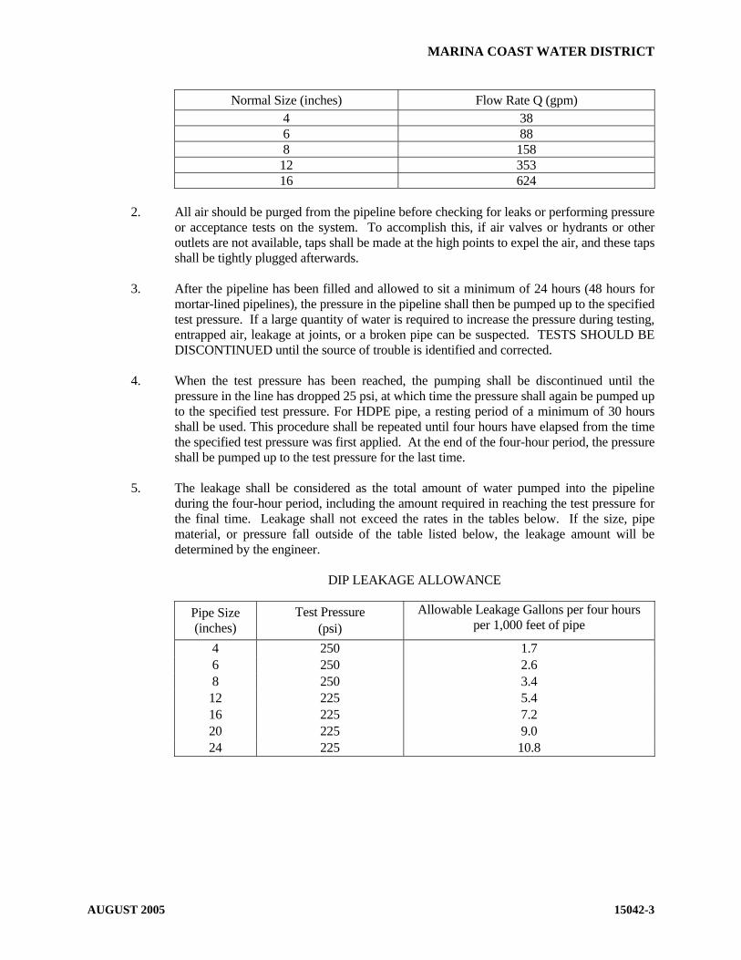
MARINA COAST WATER DISTRICT
AUGUST 2005 15042-3
Normal Size (inches) Flow Rate Q (gpm) 4 38 6 88 8 158 12 353 16 624
2. All air should be purged from the pipeline before checking for leaks or performing pressure
or acceptance tests on the system. To accomplish this, if air valves or hydrants or other outlets are not available, taps shall be made at the high points to expel the air, and these taps shall be tightly plugged afterwards.
3. After the pipeline has been filled and allowed to sit a minimum of 24 hours (48 hours for
mortar-lined pipelines), the pressure in the pipeline shall then be pumped up to the specified test pressure. If a large quantity of water is required to increase the pressure during testing, entrapped air, leakage at joints, or a broken pipe can be suspected. TESTS SHOULD BE DISCONTINUED until the source of trouble is identified and corrected.
4. When the test pressure has been reached, the pumping shall be discontinued until the
pressure in the line has dropped 25 psi, at which time the pressure shall again be pumped up to the specified test pressure. For HDPE pipe, a resting period of a minimum of 30 hours shall be used. This procedure shall be repeated until four hours have elapsed from the time the specified test pressure was first applied. At the end of the four-hour period, the pressure shall be pumped up to the test pressure for the last time.
5. The leakage shall be considered as the total amount of water pumped into the pipeline
during the four-hour period, including the amount required in reaching the test pressure for the final time. Leakage shall not exceed the rates in the tables below. If the size, pipe material, or pressure fall outside of the table listed below, the leakage amount will be determined by the engineer.
DIP LEAKAGE ALLOWANCE
Pipe Size (inches)
Test Pressure (psi)
Allowable Leakage Gallons per four hours per 1,000 feet of pipe
4 250 1.7 6 250 2.6 8 250 3.4 12 225 5.4 16 225 7.2 20 225 9.0 24 225 10.8

MARINA COAST WATER DISTRICT
AUGUST 2005 15042-4
PVC LEAKAGE ALLOWANCE
Test Pressure Allowable Leakage Gallons per four hours per 1,000 feet of pipe
Pipe Size (inches)
Class 150 (psi)
Class 200 (psi) Class 150 Class 200
4 200 250 1.5 1.7 6 200 250 2.3 2.6 8 200 250 3.0 3.4 12 225 250 5.1 5.7
STEEL PIPE ALLOWANCE For steel pipe, the allowable loss rate shall be determined by the following formula:
L=HND(P)2 7,400
In which:
L = Allowable loss (gallons) H = Specific test period (hours) N = Number of rubber-gasketed joints in the pipe tested * D = Diameter of the pipe in inches P = Specified test pressure (psig)
* Flanged, welded and grooved joints shall have zero leakage. The test period shall be four
hours for 24-inches in diameter and smaller pipe. The test period shall be eight hours for pipes greater than 24-inches in diameter.
6. Any noticeable leak shall be stopped and all defective pipe, fittings, valves, and other
accessories discovered in consequence of the test shall be removed and replaced by the contractor with sound material, and the test shall be repeated until the total leakage during a test of four hours (4) duration does not exceed the rate specified above.
END OF SECTION

MARINA COAST WATER DISTRICT
AUGUST 2005 15043-1
STANDARD SPECIFICATIONS
SECTION 15043
LEAKAGE AND INFILTRATION TESTING OF NON-PRESSURE PIPELINES PART - 1 GENERAL A. Description This section describes the requirements and procedures for leakage and infiltration testing of
gravity sewer systems, in accordance with ANSI/ASTM C828, Low Pressure Air Test. B. Related Work Specified Elsewhere 1. PVC Sewer Pipe: 02715 2. Hydrostatic Testing of Pressure Pipelines: 15042 C. Testing 1. General: All tests shall be made in the presence of the District representative. 2. Leakage: Each section of sewer between two successive manholes shall be tested for
leakage and the leakage test shall be made on all manholes. 3. Infiltration: The infiltration test shall be made where excessive groundwater is
encountered in the trench. 4. Retesting: Even though a section may have previously passed the leakage or infiltration
test, each section of sewer shall be tested subsequent to the last backfill compacting operation if, in the opinion of the District representative, heavy compaction equipment or any of the operations of the contractor or others may have damaged or affected the structural integrity or watertightness of the pipe, structure, and appurtenances.
5. Other Utilities: Official District tests will not be made until after all the other utilities
have been installed and their trench compaction verified. 6. Excessive Leakage or Infiltration: If the leakage or infiltration rate is greater than the
amount specified, the pipe joints shall be repaired or, if necessary, the pipe shall be removed and relaid by the contractor.
7. Acceptance: The sewer will not be accepted until the leakage or infiltration rate, as
determined by test, is less than the maximum allowable. 8. House Laterals: House laterals are not to be connected until after the sewer main has
been successfully tested. 9. Force Mains: Force mains shall be pressure tested per section 15042.

MARINA COAST WATER DISTRICT
AUGUST 2005 15043-2
PART 2 - MATERIALS The contractor shall furnish all equipment and materials required for testing. PART 3 - EXECUTION A. Air Test for PVC Gravity Sewers 1. Test Section: Each section of sewer between two successive manholes shall be tested by
plugging all pipe outlets with suitable test plugs. 2. Addition of Air: Air shall be slowly added until the internal pressure is raised to 4.0
pounds per square inch gage (psig). The compressor used to add air to the pipe shall have a blowoff valve set at 5 psig to ensure that at no time the internal pressure in the pipe exceeds 5 psig.
3. Internal Pressure: The internal pressure of 4 psig shall be maintained for at least two
minutes to allow the air temperature to stabilize, after which the air supply shall be disconnected and the pressure allowed to decrease to 3.5 psig.
4. Minimum Duration for Allowable Pressure Drop: The time in minutes that is required
for the internal air pressure to drop from 3.5 psig to 3.0 psig shall be measured. The results shall not be less than the minimum permissible duration for air test pressure drop shown in Table I.
TABLE I
MINIMUM DURUATION FOR AIR TEST PRESSURE DROP
Pipe Size (Inches)
Time (Minutes)
4 2-1/2 6 4 8 5
10 6-1/2 12 7-1/2 15 9-1/2
5. Retest: If the pressure drop from 3.5 psig to 3.0 psig occurs in less time than the above-
tabulated or calculated values, the pipe shall be overhauled and, if necessary, replaced and relaid until the joints and pipe shall hold satisfactorily under this test.
B. Infiltration Test 1. Preparation of Test Section: The end of the sewer at the upper structure shall be closed to
prevent the entrance of water, and pumping of groundwater shall be discontinued for at least three days, after which the section shall be tested for infiltration.
2. Allowable Infiltration Rate: The infiltration shall not exceed 0.025 gpm per inch of
diameter per 1,000 feet of main line sewer being tested, not including the length of laterals entering that section.

MARINA COAST WATER DISTRICT
AUGUST 2005 15043-3
3. Excessive Infiltration: Where infiltration in excess of the allowable amount is discovered before completion and acceptance of the sewer, the sewer shall be immediately uncovered and the amount of the infiltration reduced to a quality within the specified amount of infiltration, before the sewer is accepted.
4. Individual Leaks: Even if the infiltration is less than the allowable amount, any
individual leaks that may be observed shall be stopped as ordered by the District representative.
5. Completion of Tests: All tests must be completed before the street or trench is
resurfaced, unless otherwise directed by the District representative. C. Deflection Test 1. General: All PVC main line pipe shall be tested for deflection, joint displacement, or
other obstruction by passing a rigid mandrel through the pipe by hand, not less than 30 days after completion of the trench backfill, but prior to permanent resurfacing. The mandrel shall be a full circle, solid cylinder, or a cylinder, approved by the District as to design and manufacture. The circular cross section of the mandrel shall have a diameter of at least 95 percent of the specified average inside pipe diameter of the pipe, as follows:
Pipe Material Nominal Size Inches
Minimum Mandrel Diameter Inches
PVC-ASTM D 3033 6 5.169 (SDR 35) 8 7.309
10 9.137 12 10.963
D. Manhole Test (If required in the contract specifications) 1. General: Water tightness of manholes shall be tested in connection with tests of sanitary
sewers, or at the time the manhole is completed and backfilled. 2. Plugs: All manhole inlets and outlets shall be plugged with approved stoppers or plugs. 3. Fill Level: The manhole shall be filled with water to 2-inches below the bottom of the
tapered cone section, with a minimum depth of 4 feet and a maximum depth of 20 feet. The water shall stand in the manhole for a minimum of one hour to allow the manhole material to reach maximum absorption. Before the test is begun, the manhole shall be refilled to the original depth as needed.
4. Test Requirements: The drop in water surface shall be recorded after a period of from 15
minutes to one hour. The time of the test shall be determined by the District representative and may be varied to fit the various field conditions. The maximum allowable drop in the water surface shall be 1/2 inch for each 15-minute period of testing.
5. Visible Leaks: Even though the leakage is less than the specified amount, the contractor
shall stop any leaks that may be observed, to the satisfaction of the District representative.
END OF SECTION

MARINA COAST WATER DISTRICT
NOVEMBER 2007 15050-1
STANDARD SPECIFICATIONS
SECTION 15050
HOT TAP CONNECTIONS PART 1 - GENERAL A. Description This section describes materials, requirements and procedures for hot tap (system under pressure)
connections to existing distribution systems. B. Related Work Specified Elsewhere
1. Existing Facilities 01045
2. Chlorination of Domestic Water Mains for Disinfection 15041
3. Hydrostatic Testing of Pressure Pipelines 15042
4. Copper, Brass and Bronze Pipe, Fittings and Appurtenances 15057
5. Manual Valves 15100 C. Approved Manufacturers
1. Service Saddles and Corporation Stops See Section 15057
2. Tapping Sleeves Mueller JCM 432
3. Tapping Valves
See Resilient Seated Wedge Gate Valves Section 15100
D. Direct Tap
All taps into existing pipes will be made through a service saddle, tapping sleeve, welded nozzle or welded coupling. Taps of the same size as the pipe are not permitted. Size on size connections shall be tees. Saddles are required for all taps. Direct taps are not permitted.

MARINA COAST WATER DISTRICT
NOVEMBER 2007 15050-2
PART 2 – MATERIALS A. Service Saddles and Corporation Stops
Service saddles and corporation stops shall comply with Section 15057.
B. Tapping Sleeves
1. Tapping sleeves onto pipelines 12-inch and smaller shall be full circle cast iron with mechanical joint end glands or fabricated stainless steel or as approved by District Engineer.
2. Gaskets shall be Bunz-N rubber with a wide cross section.
3. Tapping sleeves onto 14-inch and larger ACP shall be fabricated steel with mechanical
joint ends. All fabricated parts shall be epoxy coated per Section 09900. All bolts and trim hardware shall be Type 316 stainless steel.
C. Tapping Valves
Tapping valves shall be flanged resilient seat wedge gate valves per Section 15100.
D. Weld Nozzles
Weld nozzles and reinforcing plates shall be fabricated steel per Section 15076.
PART 3 – EXECUTION A. Notification
The contractor shall provide proper notification to the District inspector prior to making a hot tap connection per Section 01045.
B. Verification
The contractor shall pothole the proposed connection to verify the outside diameter, location and type of pipe to be tapped.
C. Surface Preparation
The pipe barrel to be tapped shall be thoroughly cleaned with a wire brush to provide a smooth, hard surface for the saddle, sleeve or nozzle.
D. Service Saddle and Corporation Stop
Service saddles and corporation stops will be installed onto ACP, DIP or PVC mains in accordance with the manufacturer’s accordance and Section 15057. The outlet shall be oriented to comply with the intended use of the service connection.

MARINA COAST WATER DISTRICT
NOVEMBER 2007 15050-3
E. Tapping Sleeves 1. The tapping sleeve shall be installed in accordance with the manufacturer's instructions and
to the satisfaction of the District representative. 2. The pipe barrel shall be thoroughly cleaned with a wire brush to provide a smooth, hard
surface for the sleeve. 3. The sleeve shall be supported independent of the pipe during the tapping operation. 4. The sleeve shall be pressure tested in the presence of the District representative prior to
tapping.
5. Thrust blocks shall be provided at the tapping sleeve per Standard Plan W-17 03300. F. Tapping Valve
The tapping valve shall be installed on the tapping sleeve or weld nozzle per Section 15100. All flange bolts shall be Type 316 stainless steel.
G. Hot Tap
1. The hot tap into the existing pipe shall be made using the appropriate type of cutting machine and shell cutting bit for the material being tapped.
2. The company performing the hot tap must be approved by the District. The tapping
machine shall be operated per the manufacturer’s operating instructions.
3. Proper care shall be taken to prevent cutting material from entering the pipeline. The tapping coupon must be extracted.
H. Exterior Coating Repair
The exterior bituminous or mortar coating on steel or iron pipe shall be repaired in accordance with the manufacturer’s directions and/or Section 09900.
I. Disinfection
The interior of the tapping valve and connecting piping shall be sprayed with a sodium hypochlorite solution prior to connection.
END OF SECTION
MARINA COAST WATER DISTRICT
NOVEMBER 2007 15056-1
STANDARD SPECIFICATIONS
SECTION 15056
DUCTILE-IRON PIPE AND FITTINGS PART 1 - GENERAL A. Description This section includes materials, installation, and testing of ductile-iron pipe and fittings. B. Related Work Specified Elsewhere All related work specified elsewhere, or in other codes or standards, will be as last revised, unless a
specific date of issuance is called out in opposition to later revision date(s). Other sections of the technical specifications, not referenced below, shall also apply to the extent
required for proper performance of this work. 1. Trenching, Backfilling, and Compacting: 02223 2. Concrete: 03300 3. Corrosion Protection and Joint Bonding 13110 4. Chlorination of Domestic Water Mains for Disinfection: 15041 5. Hydrostatic Testing of Pressure Pipelines: 15042 C. Approved Manufacturers 1. Fittings Tyler Trinity Valley Dayton Sigma One Bolt Or equal 2. Pipe Pacific States U.S. Pipe American Pipe Or equal 3. Gaskets Johns Manville 109 Tripac 2000 John Crane Company Style 777
MARINA COAST WATER DISTRICT
NOVEMBER 2007 15056-2
US Pipe Or equal D. Use of Gray-Iron Fittings Gray-iron fittings may not be substituted for ductile-iron. E. Submittals
Contractor shall provide submittals for review and approval by the engineer in accordance with these specifications.
PART 2 - MATERIALS A. Ductile-Iron Pipe 1. Pressure class or thickness class of DIP shall be determined by the design method detailed
in AWWA C150 the "Thickness Design Method." 2. Ductile-iron pipe shall be manufactured in accordance with AWWA C151. 3. All ductile-iron pipe shall be pressure class shown on the plans for bell and spigot pipe.
Flanged pipe shall be thickness class 53 unless indicated otherwise. 4. All domestic and recycled water ductile-iron pipe shall be cement-mortar lined in
accordance with AWWA C104. 5. Unless otherwise called out on the plans, a "push-on" type joint shall be used. The joint
dimensions and gasket shall be as specified in AWWA C111. 6. Where restrained joints are called, push-on joints shall be restrained with locking gasket
rated for 250 psi operating pressure for DIP.
7. Flanges for ductile-iron pipe shall be the "screwed-on" type in accordance with AWWA C115.
8. Outlets for DIP shall be as follows: 2” or smaller: bronze service saddle 2-1/2”: tapped tee or service saddle 4” to 8”and larger: D.I. tee fitting or service saddle 12” and larger D.I. tee fitting 9. All buried ductile iron pipe for domestic and recycled water use shall have a factory applied
bituminous coating of not less than 1 mil. in thickness. 10. All ductile iron pipe and fittings in sewer applications shall be polyurethane or polyethylene
lined.

MARINA COAST WATER DISTRICT
NOVEMBER 2007 15056-3
B. Ductile-Iron Fittings for PVC and Ductile Iron Pipe 1. Ductile-iron fittings shall be manufactured in accordance with AWWA C110 or C153. All
fittings shall be epoxy coated and epoxy lined per AWWA C116. 2. Non-restrained fittings may be used where a thrust block is used. Non-restrained fittings
may be mechanical to mechanical fittings, mechanical to flange fittings, one-bolt fittings, and flange to flange fittings. Push-on to push-on fittings shall not be used unless restraints are provided as described below.
Restrained fittings shall be used where a thrust block is not specified. Where restrained joints are called, push-on joints shall be restrained with locking gasket rated for 250 psi operating pressure for DIP. Push-on joints shall be restrained with a mechanical type bell restraint for C-900 PVC pipe. Mechanical joint restraints shall be EBBA IRON, INC., MEGALUG, UNIFLANGE Series 1400, One-Bolt, or approved equal. Flanged fittings may be used. All fittings shall consist of stainless steel bolts and nuts, except wedge bolts, etc.
3. All buried ductile iron fittings shall have a factory applied bituminous coating of not less
than 1 mil in thickness. 4. Unless otherwise indicated on the drawings, all fittings with flanged ends shall be ductile
iron class 150. The gasket surface shall have a serrated finish of approximately 16 serrations per inch, approximately 1/32-inch deep, with serrations in either a concentric or spiral pattern. All flanges shall be flat faced. In addition, all flanges shall meet the following tolerances:
Bolt circle drilling +1/16 inch Bolt hole spacing +1/32 inch Eccentricity of bolt circle and +1/32 inch Maximum facing with respect to bore C. Gaskets
1. Gaskets for flanged joints shall be 1/8-inch thick, cloth-inserted rubber. Full face type gaskets with pre-punched holes shall be used where both flanges are flat face. Ring gaskets extending to the inner edge of the bolts may be used where a raised face flange is present.
2. Rubber gaskets for push-on joints shall be synthetic or natural rubber manufactured in
accordance with AWWA C111. D. Bolts and Nuts 1. All bolts and nuts shall be Type 316 stainless steel conforming to ASTM F593 G or H for
bolts, and ASTM F594 with Tripac 2000 Blue Coating for nuts. 2. The length of each bolt or stud shall be such that between 1/4 inch and 3/8 inch will project
through the nut when drawn tight.

MARINA COAST WATER DISTRICT
NOVEMBER 2007 15056-4
E. Plastic Film Wrap All ductile-iron pipe and fittings buried underground shall be protected with plastic film
wrap in accordance with AWWA C105, unless noted otherwise below. Wrap shall be a loose 8-mil-thick polyethylene tube. All joints between plastic tubes shall be wrapped with 2-inch-wide polyethylene adhesive tape, Polyken 900, Scotch wrap 50, or approved equal.
F. Polyethylene Lining for Sewer Applications 1. Lining material for ductile iron pipe and fittings (sewer applications) shall be virgin
polyethylene complying with ASTM D1248 and bonded to the interior of the pipe fittings by heat process. The lining material shall be compounded with inert filler and a compound which resists ultraviolet light.
2. The lining shall cover the interior surface of the pipe/fitting from the lain or beveled end to
the rear of the gasket socket. The lining thickness shall be not less than 20 mils. The lining may taper at the ends, starting at 4 inches from the edge of the pipe. The minimum thickness at the end of the taper shall be 10 mils.
3. Each pipe shall be guaranteed against separation of the lining from the pipe. Random
checks for operation will be made during construction and any indication of separation shall be cause for rejection. The test method shall be mutually agreed upon by the contractor and the District.
G. Polyurethane Lining System
1. The lining material shall consist of a liquid-applied polyurethane coating especially formulated for use as a protective lining of pipelines carrying sewage. The material shall be Corropipe II Wasteliner or approved equal. The dry film thickness (DFT) of the lining shall be 40 mils (0.040 inch) nominal.
2. In order to minimize potential dimensional and assembly problems, the coating thickness
on sealing areas in the bell socket interior and on the spigot end of the pipe exterior shall be 8 mils (0.008 inch) nominal with a maximum of 10 mils (0.010 inch). Thicker coatings in these areas are acceptable if it is demonstrated that joint dimensions are within allowable tolerances after coatings.
3. The lining material shall be applied to the pipe and fittings by an applicator certified or
approved by the coating manufacturer. The coating shall be holiday tested with a high voltage tester at 50 volts/mil of material thickness. The material shall be applied and repaired to the pipes and fittings in strict accordance with the manufacturer’s requirements with no exceptions. District shall be notified five (5) days in advance of the coating installation for factory inspection during the application of the material.
4. All field cut ends shall be repaired and sealed prior to installation per the manufacturer’s
recommendations. H. Lubricants Lubricant for pipe insertion shall be NSF food grade, and biodegradable.

MARINA COAST WATER DISTRICT
NOVEMBER 2007 15056-5
PART 3 - EXECUTION A. General Ductile-iron pipe and ductile iron fittings shall be installed in accordance with the applicable
Sections of AWWA C600 and as specified herein. B. Trenching, Backfilling, and Compacting 1. Trenching, backfilling, and compacting shall be in accordance with Section 02223 and as
specified herein. 2. Backfill within the pipe zone, including the pipe base, shall be imported sand placed and
compacted in accordance with Section 02223. 3. Backfill within the trench zone shall be native earth backfill placed and compacted in
accordance with Section 02223. C. Placement of Pipe in Trench 1. Lay pipes uphill if the grade exceeds 10%. 2. The radius of curvature of the trench shall determine the maximum length of pipe section
that can be used without exceeding the allowable deflection at a joint. Combined deflections at rubber gasket, restrained joint, deflection coupling or flexible coupling joints shall not exceed 2 degrees or that recommended by the manufacturer, if smaller.
The manufacturer's printed installation guide outlining the radius of curvature that can be
negotiated with pipe sections of various length and the deflection couplings shall be followed if applicable.
3. The pipe shall be laid true to the line and grade shown on the plans within acceptable
tolerances. The tolerance on grade is 1 inch. The tolerance on line is 2 inches. 4. Wrap ductile-iron pipe and fittings with plastic film wrap in accordance with AWWA
C105. 5. Fittings shall be supported independently of the pipe. 6. Until thrust blocks and supports are poured, fittings shall be temporarily supported by
placing wooden skids under the bells so that the pipe is not subjected to the weight of the fitting.
7. All exposed flanges and other metal surfaces and all damaged coatings shall be coated after
assembly with a mastic, 3M, Minnesota Mining and Manufacturing EC 244, or an approved equal. Stainless steel bolts shall not be coated.

MARINA COAST WATER DISTRICT
NOVEMBER 2007 15056-6
D. Anchors and Thrust Blocks Concrete anchors and thrust blocks shall be poured against wetted undisturbed soil in accordance
with Section 03300 and MCWD Standard Plans W-13, and W-14. E. Flanged Connections
1. Bolt holes of flanges shall straddle the horizontal and vertical centerlines of the pipe run. 2. Clean flanges by wire brushing before installing gasket. 3. Clean flange bolts and nuts by wire brushing, lubricate threads with anti-seize compound,
and tighten nuts uniformly and progressively. Between 1/4 inch and 3/8 inch shall project through the nut when drawn tight.
4. If flanges leak under pressure testing, loosen or remove the nuts and bolts, reseat or replace
the gasket, reinstall or retighten the bolts and nuts, and retest the joints. Joints shall be watertight.
F. Pipe Support All exposed pipe shall be supported as detailed in the plans. G. Disinfection All domestic water piping shall be disinfected by chlorination in accordance with Section 15041. H. Testing All domestic water and recycled water piping shall be hydrostatically pressure tested in accordance
with Section 15042. I. Bonding Bonding of joints to provide continuity for cathodic protection shall be as specifically shown on the
project plans, or directed by the District representative. Bonding of joints shall be per Section 13110.
END OF SECTION

MARINA COAST WATER DISTRICT
NOVEMBER 2007 15057-1
STANDARD SPECIFICATIONS
SECTION 15057
COPPER, BRASS, AND BRONZE PIPE FITTINGS AND APPURTENANCES
PART 1 - GENERAL A. Description This section includes materials and installation of copper, brass, and bronze pipe, fittings and
appurtenances. B. Approved Manufacturers 1. All materials shall be the appropriate model number specified on MCWD Standard Plans
W-1, W-2, W-3, and W-4 as manufactured by the companies listed herein or approved equal.
2. Copper Tubing Cambridge Lee 3. Service Saddle Jones Mueller Ford A.Y. McDonald 4. Corporation Stop Jones Mueller Ford A.Y. McDonald 5. Insulating Pipe Bushings, Unions, or Couplings Pipeline Coating and Engineering Co. 1566 East Slauson Avenue, Los Angeles Smith Blair Pipe Seal and Insulator Company PART 2 - MATERIALS A. Copper Tubing 1. Copper tubing shall conform to the requirements of ASTM B 88 for seamless copper water
tube. Piping located aboveground or suspended within vaults shall be Type L. Buried piping shall be Type K. Copper pipe shall be of domestic manufacture. Compression joints for connections are allowed if approved by the District Engineer.

MARINA COAST WATER DISTRICT
NOVEMBER 2007 15057-2
2. If indicated in soils report, all copper lines shall be encased within a 8-mil polyethylene sleeve. Sleeves shall be color coded per Section 15151.
B. Brass Pipe, Nipples, and Fittings Short threaded nipples, brass pipe and fittings shall conform to ASTM B 43, regular wall thickness,
except that nipples and pipe of sizes 1-inch and smaller shall be extra strong. Threads shall conform to ANSI B2.1.
C. Bronze Appurtenances 1. All items specified herein shall be manufactured of bronze conforming to ASTM B 62,
"Composition Brass or Ounce Metal Castings." 2. All size service saddles shall be of the double-strap type for any type of pipe. The straps
(or bails) shall be flat and shall be manufactured of bronze for ACP and of stainless steel for C900 PVC and ductile iron pipe. The body shall be manufactured of bronze and shall be tapped for an iron pipe thread. The seal with the pipe shall be affected with either a rubber gasket or an O-ring.
3. Corporation stops shall be ball valve type and shall be manufactured of bronze. The inlet
fitting shall be a male iron pipe thread when used with saddle and the outlet connection shall be a compression type.
4. Copper setters shall be for 1-inch and 2-inch meter sizes or as approved by the District
Engineer and using lead free solder. The inlet and outlet service line connections shall be for 1-inch services and for horizontal connections using compression type connections. A dual purpose type connection may be used for the outlet service line connection. The meter connection shall have a key type inlet and outlet valve. When using a copper setter that is sized larger than the meter, use appropriate adaptors as approved by the Engineer. Copper setters shall be 15-inches in height with a lock wing.
PART 3 - EXECUTION A. Copper Tubing and Fittings 1. Cut tubing square using a cutter designed for cutting copper tubing and remove burrs.
Clean both the inside and outside of fitting and pipe ends with steel wool and muriatic acid. Prevent annealing of fittings and tubing when making connections. Do not miter joints for elbows or notch straight runs of pipe for tees.
2. Threads of fittings shall receive a liberal coating of pipe thread compound conforming with
the requirements of ASTM B88, Type K. 3. Any damage to the fitting including but not limited to evidence of overtightening,
misaligned threads, burring or scarring of machined faces, or any evidence of leakage shall be cause for rejection. If a leak is found to be caused by debris, the debris shall be cleared and the fitting visually inspected for damage before being charged. If the leak recurs upon charging of the line, the fitting shall be removed and replaced whether or not the cause can be determined.

MARINA COAST WATER DISTRICT
NOVEMBER 2007 15057-3
4. Bends in soft copper tubing shall be long sweep. Shape bends with shaping tools. Form
bends without flattening, buckling, or thinning the tubing wall at any point. 5. Buried piping shall be installed with some slack to provide flexibility in the event of a load
due to settlement, expansion or contraction. A MINIMUM COVER OF 24 INCHES BELOW THE FINISHED STREET GRADE SHALL BE ADHERED TO. The tubing is to be bedded and covered with sand or select material as determined by the District representative.
6. All domestic service laterals shall be 1-inch minimum size copper tubing. End connections
shall be compression type. 7. All 2-inch size services shall be installed with straight lengths of soft copper water tube
Type K. End connections shall be compression type.
8. The service line shall extend perpendicular to the centerline of the street from the water main to the meter stop or structure, except in a cul-de-sac, where the service shall run in a straight line from the water main to the meter stop.
9. The service line shall be placed within an 8-mil polyethylene sleeve, color-coded for the
type of service. The ends and splices in the sleeve shall be sealed with 20-mil tape. B. Service Saddle 1. The service saddle shall be no closer than 18 inches to a valve, coupling, joint, or fitting. 2. The surface of the pipe shall be filed to remove all loose material and to provide a hard,
clean surface before placing the service saddle. 3. The service saddle shall be tightened per manufacturer’s recommendation. Care shall be
used to prevent damage or distortion of either the corporation stop or service saddle by over tightening.
4. The tap into the pipe shall be made in accordance with the pipe manufacturer's
recommendation. C. Installing Flange Bolts and Nuts 1. Lubricate bolt threads with anti-seize compound prior to installation. 2. Set flanged pipe with the flange bolt holes straddling the pipe horizontal and vertical
centerlines. D. Insulating Bushings and Unions Pipe or fittings made of nonferrous metals shall be isolated from ferrous metals by nylon insulating
pipe bushings, union, or couplings. E. Backfill Material

MARINA COAST WATER DISTRICT
NOVEMBER 2007 15057-4
The pipe zone material for all service laterals shall be compacted sand per Section 02223.
END OF SECTION

MARINA COAST WATER DISTRICT
OCTOBER 2007 15058-1
STANDARD SPECIFICATIONS
SECTION 15058
POLYETHYLENE PIPE PART 1 - GENERAL A. Description This section includes materials and installation of polyethylene pipe and tubing. B. Approved Manufacturers 1. Polyethylene Tubing Chevron Phillips JMM Or Equal 2. Stainless Steel Inserts Ford Meter Box Or Equal PART 2 - MATERIALS A. Polyethylene (PE) Tubing 1. PE tubing shall conform to the requirements of AWWA C901 for PE pressure pipe and
tubing. Tubing shall be 1-inch or 2-inch, copper tubing size (CTS) for use with compression fittings.
2. PE shall have colored stripe for type of service (blue for potable or purple for irrigation). If
unstriped, provide color coded 8-mil polyethylene sleeve as for copper tubing. Sleeves shall be color coded per Section 15151.
B. Stainless Steel Inserts 1. Insert stiffeners for use with compression fittings shall be tubular stainless steel, grade 304,
with flared/flanged end. Match to PE tubing size. PART 3 - EXECUTION A. PE Tubing and Fittings 1. Cut tubing square using a cutter designed for cutting PE tubing and remove burrs. Clean
both the inside and outside of fitting and pipe ends per manufacturers instructions. Use stainless steel inserts at all compression fittings.

MARINA COAST WATER DISTRICT
OCTOBER 2007 15058-2
2. Install a single piece of PE tubing from the corp stop to the copper setter or angle stop. Splices and fittings shall be heat fusion welded per the manufacturers directions. Compression fittings are not allowed other than at the ends.
3. Bends in PE tubing shall be long sweep. Form bends without flattening, buckling, or
thinning the tubing wall at any point. 4. Any damage to the fitting including but not limited to evidence of overtightening,
misaligned threads, burring or scarring of machined faces, or any evidence of leakage shall be cause for rejection. If a leak is found to be caused by debris, the debris shall be cleared and the fitting visually inspected for damage before being charged. If the leak recurs upon charging of the line, the fitting shall be removed and replaced whether or not the cause can be determined.
5. Buried piping shall be installed with some slack to provide flexibility in the event of a load
due to settlement, expansion or contraction. A MINIMUM COVER OF 24 INCHES BELOW THE FINISHED STREET GRADE SHALL BE ADHERED TO. The tubing is to be bedded and covered with sand or select material as determined by the District representative.
6. All domestic service laterals shall be 1-inch minimum PE or copper tubing. End
connections shall be compression type. 7. All 2-inch size services shall be installed with straight lengths of PE or soft copper water
tube Type K. End connections shall be compression type.
8. The service line shall extend perpendicular to the centerline of the street from the water main to the meter stop or structure, except in a cul-de-sac, where the service shall run in a straight line from the water main to the meter stop.
9. The service line shall have a colored stripe or be placed within an 8-mil polyethylene
sleeve, color-coded for the type of service. The ends and splices in the sleeve shall be sealed with 20-mil tape.
10. PE tubing may be clamped to allow for relocating the copper setter or angle stop. Use a
smooth-faced clamp designed for PE tubing that will not scar the pipe. E. Backfill Material
The pipe zone material for all service laterals shall be compacted sand per Section 02223.
END OF SECTION

MARINA COAST WATER DISTRICT
NOVEMBER 2007 15064-1
STANDARD SPECIFICATIONS
SECTION 15064
PVC PRESSURE DISTRIBUTION PIPE PART 1 - GENERAL A. Description This section includes materials, installation, and testing of polyvinyl chloride (PVC) distribution
pipe. B. Related Work Specified Elsewhere All related work specified elsewhere, or in other codes or standards, will be as last revised, unless a
specific date of issuance is called out in opposition to later revision date(s). Other sections of the technical specifications, not referenced below, shall also apply to the extent
required for proper performance of this work. 1. Trenching, Backfilling, and Compacting: 02223 2. Jacked Casing: 02315 3. Concrete: 03300 4. Painting and Coating: 09900 5. Chlorination of Domestic Water Mains for Disinfection: 15041 6. Hydrostatic Testing of Pressure Pipe: 15042 7. Ductile-Iron Pipe and Fittings: 15056 8. Copper, Brass and Bronze Pipe, Fittings, and Appurtenances: 15057 9. Combination Air and Vacuum Release Assembly: 15089 10. Manual Valves: 15100 11. Underground Facilities Identification: 15151 C. Approved Manufacturers 1. J-M Manufacturing 2. Vinyltech

MARINA COAST WATER DISTRICT
NOVEMBER 2007 15064-2
3. P W Pipe
4. Certainteed 5. Diamond Plastics
D. Application 1. Class 150PVC Pipe shall be used unless specifically shown otherwise on the plans. 2. PVC pipe shall be used as a valve can riser. E. Reference Standard Conform to AWWA C900, "Polyvinyl Chloride (PVC) Pressure Pipe, 4-inch through 12-inch for
Water" or AWWA C905, "Polyvinyl Chloride (PVC) Pressure Pipe, 14-inch through 48-inch for Water Transmission and Distribution”, as applicable unless noted otherwise below. Where C900 is used, C905 is implied for larger pipe.
PART 2 - MATERIALS A. PVC Pipe 1. PVC pipe shall be manufactured in accordance with AWWA C900. The pipe shall have
gasket bell end or plain end with elastomeric gasket coupling. 2. Laying lengths shall be 20 feet with the manufacturer's option to supply up to 15% random
(minimum length 10 feet). 3. Each pipe length shall be marked showing the nominal pipe size and O.D. base, the
AWWA pressure class, and the AWWA specification designation (AWWA C900). For domestic water application, the seal of the testing agency that verified the suitability of the material for such service shall be included.
4. Pipe for recycled lines shall be purple in color and marked as detailed in Section 15151. B. Fittings Fittings shall be ductile-iron conforming to Section 15056. C. Manual Valves Manual valves shall conform with Section 15100. D. Service Saddles All service saddles shall be designed for use on C900 PVC pipe and in accordance with Section
15057. E. Lubricants

MARINA COAST WATER DISTRICT
NOVEMBER 2007 15064-3
Lubricant for pipe insertion shall be NSF food grade, and biodegradable. PART 3 - EXECUTION A. General 1. The contractor shall install all the pipe, closure sections, fittings, valves, and appurtenances
shown including pipe supports, bolts, nuts, gaskets, and jointing materials. 2. At all times when the work of installing pipe is not in progress, all openings into the pipe
and the ends of the pipe in the trenches or structure shall be kept tightly closed to prevent the entrance of animals and foreign materials. The contractor shall maintain the inside of the pipe clean, sanitary, and free from foreign materials until its acceptance by the District.
3. Where closure sections are required by the contractor's installation operations, the sections
shall be installed in accordance with the applicable sections of these specifications. 4. The pipe sections shall be laid in the trench to true alignment and grade in accordance with
the drawings. The pipe grade shall be approved by the District. 5. The pipe shall not be laid along curves at a radius less than that listed below: The minimum-radius curves are determined by the limit of 2-degree deflection for PVC
pipe joints with factory-assembled bell couplings: Length of Pipe Section Minimum Curve Radius 20 feet 573 feet 10 feet 287 feet For curves of smaller radius, use high- deflection couplings or ductile-iron fittings. B. Installation 1. Trenching, backfilling, and compacting shall be in accordance with Section 02223 and as
specified herein. Compacted pipe bedding material conforming to Section 02223 shall be installed in the bottom of the trench and compacted prior to placing pipe in the trench. Excavate bell holes at each joint to permit proper assembly and inspection of the entire joint and to assure the pipe is fully supported by the pipe barrel.
2. Proper care shall be used to prevent damage in handling, moving, and placing the pipe.
Tools and equipment satisfactory to the District representative shall be provided and used by the contractor.
3. The contractor shall take all necessary precautions to prevent the pipe from floating due to
water entering the trench from any source; shall assume full responsibility for any damage due to this cause; and shall pay for and perform the work to restore and replace the pipe to its specified condition and grade if any displacement occurs due to floating.
4. Pipe shall be cut by a method recommended in the pipe manufacturer's installation guide, as
approved by the District representative. When pipe is cut and is to be joined to a cast-iron

MARINA COAST WATER DISTRICT
NOVEMBER 2007 15064-4
fitting or another piece of pipe the end shall be beveled in the field or place of manufacture to create a beveled end equal in quality to the machined ends of the pipe as furnished by the manufacturer. Such machining shall not result in undercutting the wall thickness and must be approved by the District representative before installation.
5. All connecting parts of pipe, rings, couplings, and castings shall be cleaned before
assembly. After bearing has been obtained, couplings shall be assembled in a proper manner (as determined by the District representative). The use of excessive lubricant will not be permitted, and the assembly of the couplings and rings shall be in accordance with the manufacturer's recommendations. Lubricant and rubber rings shall be supplied by the pipe manufacturer. All fittings and valves shall have joints that match the type of adjoining pipe.
6. All fittings and valves shall be supported so that the pipe is not subjected to the weight of
these appurtenances. 7. End of line fittings shall be restrained by thrust blocks.
8. Concrete thrust blocks of the size shown on MCWD Standard Plans W-13 and W-14 and as
specified herein shall be provided at the location of all cast-iron fittings, valves, fire hydrants, and end of line plugs. Restrained joints are acceptable in lieu of thrust blocks.
9. Pipe and trench zone backfill shall be per Section 02223. 10. Manual valves shall be installed in accordance with Section 15100.
C. Installations within Jacked Casing 1. Certain portions of the project, such as crossings of some roads, highways, and railroads,
may be required to be installed within a jacked casing pipe. 2. The casing size and type shall be in accordance with Section 02315. 3. Work shall not proceed without permission of the District representative. Refer to MCWD
Standard Plan W-15.
4. All pipe installed within a casing shall have restrained joints. D. Combination Air and Vacuum Relief Valves 1. Air release valve assemblies and combination air and vacuum valves shall be installed at
each point in the pipeline as shown on the drawings or as specified by the District representative.
2. The tap for the air valves shall be made in a level section of pipe no closer than 18 inches to
a bell, coupling, joint, or fitting. 3. Air release valve assemblies shall be installed in accordance with MCWD Standard Plan
W-10 and Section 15089.

MARINA COAST WATER DISTRICT
NOVEMBER 2007 15064-5
E. Blow-Off Assemblies 1. Either in-line type or the end-of-line type blow off assemblies shall be installed in
accordance with the standard drawings at locations noted on the plans and at such additional locations as required by the District representative for removing water or sediment from the pipeline.
2. The assembly shall be installed in a level section of pipe. 3. The tap for blow off in the line shall be no closer than 18 inches to a valve, coupling, joint,
or fitting. 4. Blow offs shall not be connected to any sewer, submerged in any stream, or installed in any
manner that will permit back siphoning into the distribution system. 5. Blow offs shall be installed in accordance with MCWD Standard Plan W-11 and the
applicable sections of these specifications. F. Pipe Identification Warning and locator tape shall be installed on all on-site recycled water pipelines and domestic
water piping installed within the limits of a non-potable irrigation system. The pipe identification shall be in accordance with Section 15151.
G. Locator Wire A bare 10-gauge stranded copper wire shall be placed continuously on the top center of the pipe.
The wire shall not be spliced at any point, and shall be continuous from riser to riser. The wire shall be brought to the surface at valve locations and shall be accessible by removing the valve can cover. The wire shall be brought up the outside of the valve riser and folded over between the inside of the valve box and the valve riser. The wire shall be brought to within 6 inches of finish grade. The wire shall also be tapped in place by means of a plastic adhesive tape, placed at 10 foot intervals.
H. Thrust Blocks 1. Thrust blocks shall be constructed where shown on the drawings, or where directed by the
District representative and as specified herein. In general, thrust blocks will be placed at all angles greater than 5 degrees, at changes in pipe size, at fittings, at hydrant ells, and at valves.
2. Fittings used with thrust blocks shall conform to Section 15056. 3. The area and design of the bearing surface shall be per MCWD Standard Plans W-13 and
W-14. 4. The bearing surface shall be against undisturbed ground in all cases, except where unstable
conditions are encountered. In unstable conditions, the bearing surface shall be as directed by the District representative.
5. Unless otherwise directed by the District representative, the blocking shall be placed so that
the pipe and fitting joints are accessible for repair.

MARINA COAST WATER DISTRICT
NOVEMBER 2007 15064-6
6. Metal harness of tie rods and pipe clamps shall be used to prevent movement if shown on
the plans or directed by the District representative. 7. Exposed non-steel rods and clamps shall be coated with bituminous mastic per Section
09900. 8. Reinforcing steel tie-down rods shall be used on all line valves. 9. The depth of thrust blocks below valves shall conform with the size of the valve and shall
be cut into the side of the trench a minimum of 12-inches on each side. 10. Concrete for thrust blocks shall be Class "A" per Section 03300. I. Slope Protection 1. Slope protection shall be installed where shown on the plans in accordance with Section
02223, wherever the profile of the ground surface above the pipeline exceeds 20% and where no pavement or other surfacing is to be laid over the facility.
2. The installation of the slope protection shall be considered a part of the work, and the
contractor shall include the expense in the contract cost. 3. A reinforced concrete encasement may be used as directed by the District representative.
The encasement shall extend to within 1-foot of the ground surface and to within 1-foot of the toe of slope in which the pipe is constructed.
J. Disinfection All domestic water pipelines shall be disinfected in accordance with Section 15041 prior to
connection to the existing distribution system. K. Hydrostatic Testing All pipelines shall pass a hydrostatic pressure test in accordance with Section 15042. END OF SECTION
MARINA COAST WATER DISTRICT
NOVEMBER 2007 15089-1
STANDARD SPECIFICATIONS
SECTION 15089
COMBINATION AIR VACUUM / AIR-RELEASE VALVE ASSEMBLY PART 1 - GENERAL A. Description This section includes materials and installation of combination air vacuum/air-release valves. Valves are to be provided and installed per AWWA C 512, unless noted otherwise in this section. B. Application 1. Combination valves shall be installed at high points on the line or as shown on the plans. 2. If the profile changes during construction from that shown on the drawings, valve
assemblies shall be installed at the high points in lines as constructed.
3. The installation shall be complete as shown on MCWD Standard Plan W-10.
4. Combination valve assemblies shall function to slowly release pockets of air which accumulate at high points, or changes in line gradient, exhaust large quantities of air from pipeline while being filled and admit large quantities of air into pipeline when being drained to prevent air lock or vacuum collapse of the pipe.
C. Related Work Specified Elsewhere All related work specified elsewhere, or in other codes or standards, will be as last revised, unless a
specific date of issuance is called out in opposition to later revision date(s). Other sections of the technical specifications, not referenced below, shall also apply to the extent
required for proper performance of this work. 1. Concrete: 03300 2. Painting and Coating: 09900 3. Hydrostatic Testing of Pressure Pipelines: 15042 4. Copper, Brass and Bronze Pipe, Fittings and Appurtenances: 15057 5. Manual Valves: 15100

MARINA COAST WATER DISTRICT
NOVEMBER 2007 15089-2
D. Approved Manufacturers 1. APCO 2. Val-Matic 3. Crispin PART 2 - MATERIALS A. Combination Air Release Valves 1. Materials of construction for combination air and vacuum release valves shall be as
described below:
Item Material Specification Body and Cover Cast Iron ASTM A126, Class B
Float, Lever Poppet Stainless Steel ANSI Type 316 (ASTM A240 or A276)
Seat Rubber Buna-N (Chlorine Resistant)
Drain Plug Bronze 85,5,5,5 Alloy
Casing bolts/nuts Stainless Steel ANSI Type 316
2. Interior of valve shall be epoxy lined per Section 09900. Internal lining for domestic water facilities shall be NSF 61 approved epoxy to a minimum thickness of 12 mils (DFT) and holiday tested.
3. All valves 2-inch and smaller shall have threaded inlets. All valves 3-inch and larger shall
have flanged inlets.
4. For valves 4-inch and smaller, both air-vacuum and air-release functions shall be contained in one valve body. On valves 6-inch and larger, separate valves for each function piped together to function as one unit is permitted. An isolation valve shall be installed between the two units.
B. Fiberglass Air Release Valve Enclosure The fiberglass enclosure shall be as specified by the Engineer. C. Service Piping Water service piping utilized in the installation of the combination air and vacuum relief valve shall
be Type K copper with bronze accessories per Section 15057. D. PVC Pipe Sleeve PVC pipe fittings, Schedule 80.
MARINA COAST WATER DISTRICT
NOVEMBER 2007 15089-3
PART 3 - EXECUTION A. Location 1. Combination air-vacuum/air-release valves shall be installed on the pipeline as shown on
the drawings or as specified by the District representative. 2. The tap for the air valves shall be made in a level section of pipe no closer than 18 inches to
a bell, coupling, joint, or fitting. No tap shall be permitted in any machined section of ACP.
3. The center of the PVC sleeve shall be, except as otherwise approved by the District
representative, located as shown on MCWD Standard Plan W-10 as described below: a. Where concrete curb or asphalt concrete (A.C.) berm exists or is to be constructed,
and the sidewalk is next to the property line; 40 inches back of the face of the curb. b. Where 6-foot wide or narrower sidewalk is to be installed or exist next to the curb;
12 inches back of sidewalk edge. Where there is insufficient public right-of-way behind of the sidewalk, an easement will be required.
c. Where there is no curb or berm, the location shall be designated by the District. B. Installation 1. Combination valves shall be installed in accordance with MCWD Standard Plan W-10. 2. The tap and piping shall be installed per Section 15057. 3. The concrete pad and support shall be constructed per Section 03300. Riser piping shall
extend through concrete slab within a minimum 4-inch diameter PVC sleeve. 4. Clean threaded joints by wire brushing or swabbing. Apply Teflon joint compound or
Teflon tape to pipe threads before installing threaded valves. Joints shall be watertight. 5. The combination valve and the steel vented pipe cover shall be painted in accordance with
Section 09900. The final coat of paint shall be applied immediately prior to the final inspection.
6. A bronze ball valve with handle shall be installed on the copper service line above the
concrete slab. 7. Stainless steel nipple shall be installed between the shutoff valve and the air release valve. C. Valve Pressure Testing 1. Test valves at the same time that the connecting pipelines are pressure tested. See Section
15042 for pressure testing requirements.

MARINA COAST WATER DISTRICT
NOVEMBER 2007 15089-4
2. Protect or isolate any parts whose pressure rating is less than the test pressure. END OF SECTION
MARINA COAST WATER DISTRICT
NOVEMBER 2007 15100-1
STANDARD SPECIFICATIONS
SECTION 15100
MANUAL VALVES PART 1 - GENERAL A. Description This section includes materials, testing, and installation of manually operated valves. Manual valves to be supplied and installed per AWWA C 507, and C 509, unless noted otherwise
below. B. Related Work Specified Elsewhere All related work specified elsewhere, or in other codes or standards, will be as last revised, unless a
specific date of issuance is called out in opposition to later revision date(s). Other sections of the technical specifications, not referenced below, shall also apply to the extent
required for proper performance of this work. 1. Trenching, Backfilling, and Compacting: 02223 2. Concrete: 03300 3. Painting and Coating: 09900 4. Hydrostatic Testing of Pressure Pipelines: 15042 5. Ductile-Iron Pipe and Fittings: 15056 6. Underground Facilities Identification. 15151 C. Approved Manufacturers as listed or approved equal. 1. Gate Valves - Aboveground Smaller Than 2 Inch Red & White Milwaukee
2. Ball Valves Smaller than 3-inch Nibco
3. Resilient - Seated Gate Valves: 4 Inch through 12 Inch
Clow Mueller AFC

MARINA COAST WATER DISTRICT
NOVEMBER 2007 15100-2
4. Butterfly Valves Henry Pratt Company Dezurik AFC 5. Valve Boxes Christy G5 with cast iron cover D. Reference Standards Valves shall conform, as applicable, with the latest editions of the following codes and standards. AWWA C504 Rubber-Seated Butterfly Valves AWWA C509 & C515 Resilient Seated Gate Valves ASTM B62 Composition Brass or Ounce Metal Castings Ductile Iron Castings for Valves Ductile Iron Pipe Flanges ASTM D 429 Tests for Rubber Property – Adhesion to Rigid Substrates E. Flanged End All valves connecting to mains shall be flanged on at least one side and bolted to the fitting on the
main. F. Single Type of Valve The developer shall choose an approved valve and then use only that valve throughout the
development (i.e., only one manufacturer and model per type of valve). G. Detector Check and Backflow Prevention Assembly
Isolation valves on a detector check or backflow prevention assembly are to be part of an integral unit, furnished and assembled by the manufacturer of the device.
H. Butterfly Valves Butterfly valves shall only be used on lines 14 inches and larger or as specifically shown on the
plans. I. Resilient Wedge Gate Valves Resilient gate wedge valves shall be used on all pressure class 150 lines 4 inch through 12 inch. J. Field Hydrostatic Test
All valves 16-inch and larger shall be field hydrostatically tested to the valves working pressure in the presence of the District inspector. Each side of the valve shall be tested independently.

MARINA COAST WATER DISTRICT
NOVEMBER 2007 15100-3
PART 2 - MATERIALS A. General
1. Product data shall be shop drawings, manufacturer’s product data and installation instructions demonstrating that the proposed valve is in compliance with the reference standards as well as the intended service. If drawings are returned disapproved or not stamped, they shall be revised or corrected as necessary and resubmitted for review, acceptance, and stamping.
2. Certified test reports shall be provided with each delivery that the valve(s) delivered
complies with this specification. 3. Valves shall be installed complete with operating handwheels or levers, extension stems,
worm gear operators, operating nuts, and wrenches required for operation. 4. Valves shall have the name of the manufacturer and the size of the valve cast or molded
onto the valve body or bonnet or shown on a permanently attached plate. 5. Valve body and trim casting shall be of domestic origin.
6. Bolts for all valves shall be 316 stainless steel. Bolts consisting of 304 stainless steel shall not be permitted.
7. Suitable valves shall be provided to connect to adjoining piping as specified for pipe joints. B. Valve Operators 1. Provide lever or wrench operators having adjustable, "position indicator" for exposed
butterfly valves smaller than 6 inches and hand-wheels for above ground gate valves. 2. Provide 2-inch AWWA operating nuts for buried and submerged valves. 3. Provide gear operators on butterfly valves 6 inches and larger. Gear operators for valves 8-
inches and larger shall be of the traveling nut type. For large valves, worm gears shall be used with the approval of the Engineer.
4. Gear operators shall be enclosed with seals provided on shafts to prevent entry of dirt and
water into the operator. Gear operators for valves located above ground or in vaults and structures shall have handwheels. Minimum handwheel diameter shall be 12 inches. The operator shall contain a dial indicating the position of the valve disc or plug. Gear operators for buried or submerged valves shall have 2-inch square AWWA operating nuts.
5. For buried or submerged service, provide watertight shaft seals and watertight valve and
actuator cover gaskets. Provide totally enclosed operators designed for buried or submerged service.
6. Traveling nut and worm gear operators shall be of the totally enclosed design so
proportioned as to permit operation of the valve under full operating head with a maximum pull of 80 pounds on the hand-wheel. Provide stop limiting devices in the operators in the
MARINA COAST WATER DISTRICT
NOVEMBER 2007 15100-4
open and closed positions. Operators shall be of the self-locking type to prevent the disc or plug from creeping. Design operator components between the input and the stop-limiting devices to withstand without damage a pull of 200 pounds for handwheel or chainwheel operators and an input torque of 300 foot-pounds for operating nuts when operating against the stops.
7. Operators on buried valves shall produce the required torque on the operating nut with a
maximum input of 150 foot-pounds. 8. Valve operators, handwheels, or levers shall open by turning counterclockwise. C. Painting and Coating 1. Coat metal valves (except bronze and stainless-steel valves) located above ground or in
vaults and structures in accordance with Section 09900. Apply the specified prime coat at the place of manufacture. Apply finish coat in field. Finish coat shall match the color of the adjacent piping. Coat handwheels the same as the valves.
2. Coat buried metal valves at the place of manufacture per Section 09900. 3. Valves 4 inches and larger shall be coated on their interior metal surfaces excluding seating
areas and bronze and stainless steel pieces in accordance with AWWA C550 and these specifications. Sandblast surfaces in accordance with SSPC SP-5. Remove all protuberances which may produce pinholes in the lining. Round all sharp edges to be coated. Remove any contaminants which may prevent bonding of the lining. Coat the interior ferrous surfaces using one of the following methods:
a. Apply powdered thermosetting epoxy (3M Scotchkote 6251 Fusion Bonded Epoxy
or equal) per the manufacturer's application recommendations to a thickness of 7 to 9 mils. All gaskets and seals must be removed prior to applying coating.
b. Apply two coats of catalytically setting epoxy (Tnemec Series N140, or equal) to a
dry-film thickness of 7 to 9 mils total. Follow the paint manufacturer's application recommendations including minimum and maximum drying time between the required coats.
All valve coatings shall be factory applied or by the manufacturer’s qualified distributor.
Touch up and repair of valve coatings shall be only done by authorized factory distributors. D. Aboveground Ball Valves 2 Inches and Smaller 1. Aboveground threaded end ball valves, 1/4 inch through 3 inches, for water service shall be
full bore port ball type having a minimum working pressure of 200 psi. Valves shall have plastic coated lever operators.
2. Materials of construction shall be as described below:

MARINA COAST WATER DISTRICT
NOVEMBER 2007 15100-5
Component Material Specification Body Bronze ASTM B 62 Ball Stainless Steel ASTM B 62
Seat, Seals Teflon Stem Bronze or Copper silicon ASTM b 62, B 99
(Alloy 651), B 584 B 371 (Alloy 694)
3. Stem material shall have a minimum tensile strength of 60,000 psi and a minimum yield
strength of 30,000 psi. E. Resilient-Seated Wedge Gate Valves 1. Valves shall conform to AWWA C509 and C515 and the requirements listed herein. 2. All valves shall be bubble tight at 200 psi working pressure. 3. Valves shall have non-rising low-zinc stems, opening by turning counter-clockwise and
provided with 2-inch-square operating nut. Outside stem and yolk valves shall be used on backflow device shutoff valves.
4. Each valve shall have a smooth unobstructed waterway free from any sediment pockets. 5. Stuffing boxes shall by O-ring seal type with two rings located in stem. 6. Low friction torque reduction thrust bearings shall be located both above and below the
stem collar.
7. Materials shall be as described below:
Component Material Specification Body, Operating Nut
Bonnet, Seal Plate Cast Iron or Ductile Iron
ASTM A 126 Class B
Gate Cast Iron or Ductile Iron
Type 316
Bonnet and Seal Bolts
Stainless Steel Type 316
O-Rings Synthetic Rubber ASTM D2000 8. All internal working parts (excluding gate) shall be all bronze containing not more than
2 percent aluminum or more than 7 percent zinc. Valve stems shall be cast or forged from bronze having a tensile strength of not less than 60,000 psi, a yield point of not less than 30,000 psi, and an elongation of not less than 10 percent in 2 inches.
9. All gates shall be encapsulated in Buna-N rubber or a nitrile elastomer.

MARINA COAST WATER DISTRICT
NOVEMBER 2007 15100-6
F. Tapping Valves 1. Tapping valves shall conform with all requirements for gate valves 2 inches and larger and
the additional requirements listed herein. 2. All valve ends shall be flanged. The flange on one end shall have slotted bolt holes to fit all
standard tapping machines. 3. Seat rings shall be oversized to permit the use of full-size cutters. 4. Resilient wedge valves may be used as tapping valves, provided that the disk fully retracts
to produce a full port opening. G. Butterfly Valves 1. Butterfly valves shall be short body, conforming to AWWA C504, Class 150. Minimum
working differential pressure across the valve disc shall be 150 psi unless specified otherwise on the drawing.
2. Butterfly valves shall be furnished and installed with the type of ends as shown on the plans
and as herein specified. Wafer style valves will not be permitted. 3. Each valve body shall be tested under a test pressure equal to twice its design water
working pressure. 4. Valves shall be bubble tight at rated pressures and shall be satisfactory for throttling service
and frequent operation after long periods of inactivity. Valve discs shall rotate 90 degrees from the full-open position to the tight-shut position.
5. Valve ends shall be as shown on the drawings; flanged ends shall be Class 125, ANSI
B16.1. 6. Valve shafts shall be Type 316 stainless steel or carbon steel with Type 316 stainless-steel
journals and static seals. Valve shafts shall be dual stub shafts or a one-piece shaft extending completely through the valve disc.
7. Materials of construction shall be as described below:
Component Material Specification
Body Cast Iron or Ductile Iron
Exposed Body Capscrews, and Bolts and Nuts
Stainless Steel Type 316
Discs Cast Iron
Ductile Iron, or Ni-Resist
Seat Buna-N (in body)
MARINA COAST WATER DISTRICT
NOVEMBER 2007 15100-7
8. The rubber seat shall be an integral part of the valve body. Rubber seats fastened to the disc by any means shall not be permitted.
H. Bolts and Nuts for Flanged Valves Bolts and nuts for flanged valves shall be Type 316 stainless steel in accordance with Section
15056. I. Gaskets Gaskets for flanged end valves shall be as described in Section 15056. J. Valve Boxes for Buried Valves 1. Valve extension pipe material shall be 8-inch PVC SDR 35 pipe. 2. Design cast iron cap to rest within a frame on a cast-in-place concrete ring surrounding the
valve extension pipe; size the tapered skirt of the cap for a close fit inside the upper sleeve portion of the valve box. Caps for the domestic water system shall be circular with the word "WATER" cast on the cap. Caps for the recycled water system shall be circular with “RECYCLED” cast on the cap. Coat the cap and frame with asphalt or coat-tar paint.
k. Extension Stems for Buried Valve Operators 1. Where the depth of the valve is such that its centerline is more than 4 feet below grade,
provide operating extension stems to bring the operating nut to a point 24 to 30-inches below the surface of the ground and/or box cover.
2. Extension stems shall be steel and shall be complete with 2-inch-square operating nut. 3. Valve stem extensions shall be of a solid design (no pinned couplings permitted) with
guides. 4. Valve extensions shall conform with MCWD Standard Plan W-7. PART 3 - EXECUTION A. Joints 1. Bolt holes of flanged valves shall straddle the horizontal and vertical centerlines of the pipe
run to which the valves are attached. Clean flanges by wire brushing before installing flanged valves. Clean flange bolts and nuts by wire brushing, lubricate threads with oil and graphite, and tighten nuts uniformly and progressively. If flanges leak under pressure testing, loosen or remove the nuts and bolts, reseat or replace the gasket, reinstall or retighten the bolts and nuts, and retest the joints. Joints shall be watertight.
2. Clean threaded joints by wire brushing or swabbing. Apply Teflon joint compound OR
Teflon tape to pipe threads before installing threaded valves. Joints shall be watertight.

MARINA COAST WATER DISTRICT
NOVEMBER 2007 15100-8
3. Rubber ring grooves of valves shall be inspected before installation by the contractor for ridges or holes that would interfere with the rubber ring. Interferences with the rubber ring shall be corrected to a satisfactory connection or the valves replaced, as required by the District. (All valves shall have the same rubber-ring groove profile as the groove of the pipe couplings furnished with the pipe.)
B. Butterfly Valve Operators Butterfly valves shall be installed with the operators on the street centerline side of the pipeline. C. Exterior Protection 1. All exposed flanges and other metal surfaces and all damaged coatings shall be coated after
assembly with bituminous mastic per Section 09900. Coating of stainless steel flange bolts is not required.
2. Wrap buried valves with 8-mil polyethylene wrap per AWWA C105. D. Concrete Supports 1. Valves shall be anchored in concrete as shown in MCWD Standard Plan W-7. 2. Concrete supports will not be required under valves bolted to flanged fittings. 3. Until supports are poured, valves shall be temporarily supported by placing wooden skids
underneath the valve so that the pipe is not subjected to the weight of the valve. 4. All concrete anchors and thrust blocks specified or required by the District representative
are considered as part of the pipeline installation. E. Valve Boxes 1. Valve boxes shall be firmly supported and shall be kept centered and plumb over the
operating nut of the valve. 2. Beveled sections of pipe will not be allowed at the top of the valve extension pipe. The top
cut shall be square and machine made. 3. During the construction of new tracts, the valve extension pipes for "key valves" shall
extend well above the ground level to permit ease of location in case of emergency shutoffs.
4. The box cover shall be flush with the surface of the finished pavement or at any other level
designated by the District representative. F. Backfill 1. All backfill within 24 inches of a valve shall be clean, washed sand. 2. Backfill is to be placed and compacted in accordance with Section 02223.

MARINA COAST WATER DISTRICT
NOVEMBER 2007 15100-9
G. Valve Leakage Testing 1. Test valves for leakage at the same time that the connecting pipelines are tested. See
Section 15042 for pressure testing requirements. 2. Valves shall have a pressure rating higher than or equal to the test pressure. END OF SECTION

MARINA COAST WATER DISTRICT
SEPTEMBER 2003 15112-1
STANDARD SPECIFICATIONS
SECTION 15112
BACKFLOW PREVENTERS PART 1 - GENERAL A. Description This section includes materials, installation, and testing of backflow prevention assemblies. B. Related Work Specified Elsewhere All related work specified elsewhere, or in other codes or standards, will be as last revised, unless a
specific date of issuance is called out in opposition to later revision date(s). Other sections of the technical specifications, not referenced below, shall also apply to the extent
required for proper performance of this work. 1. Concrete: 03300 2. Ductile-Iron Pipe and Fittings: 15056 3. Copper, Brass, and Bronze pipe, Fittings, and Appurtenances: 15057 4. Manual Valves: 15100 5. Meters: 15150 C. Approved Assemblies The backflow prevention assembly shall be included in the latest edition of the "List of Approved
Backflow Prevention Assemblies," Foundation for Cross-Connection Control and Hydraulic Research, University of Southern California, School of Engineering.
D. Application 1. A backflow prevention device shall be installed at all locations where the potential for a
backflow condition into the District's domestic water mains exists. The device shall be located immediately behind the meter assembly.
2. The type of device required will depend on the level of potential hazard which exists. The
District Cross Connection Inspector, will make the final determination of, and what type of backflow device is required.
3. Any service providing domestic water to anything other than a private residential dwelling
shall have backflow protection.

MARINA COAST WATER DISTRICT
SEPTEMBER 2003 15112-2
4. A double check detector check assembly is required on a private on-site fire protection system or a private on-site distribution system with two or more separate connections to the District's domestic water mains.
E. Responsibility
The District will maintain only the upstream mainline shut-off valve and service to the point of connection of the assembly and the by-pass meter. The owner is responsible for the testing, maintenance and repair or replacement of the device.
PART 2 - MATERIALS A. Shut-Off Valves 1. The shut-off valves for assemblies 3-inch and larger shall be resilient seat gate valves
conforming to Section 15100. Ball valves shall be used on assemblies smaller than 3-inch. 2. Shut-off valves shall have outside stems and yokes. B. Ductile Iron Piping and Fittings Ductile iron piping and fittings shall be furnished and installed in accordance with Section 15056. C. Concrete Concrete thrust blocks and supports shall be in conformance with Section 03300. D. By-Pass Piping By-pass piping shall be copper or brass conforming with Section 15057. E. Backflow Prevention Assembly All backflow prevention assemblies shall conform to the latest edition of AWWA C506 and the
"Manual of Cross-Connection Control," Foundation for Cross-Connection Control and Hydraulic Research, University of Southern California, School of Engineering.
F. By-Pass Meter The by-pass meter shall conform with the requirements of Section 15150 and shall be compatible
with the backflow device on which it is installed. The backflow prevention assembly and the by-pass meter shall be furnished as one complete unit. All by-pass meters shall be 5/8-inch by 3/4-inch, manufactured by Invensys, with registers reading in cubic feet.
PART 3 - EXECUTION A. Installation Installation of the double detector check assembly, or a reduced pressure principle assembly will be
per MCWD Standard Plan W-4 and as noted below.
MARINA COAST WATER DISTRICT
SEPTEMBER 2003 15112-3
1. Installation shall comply with the latest plumbing codes and applicable local agency requirements.
2. Installation shall comply with the requirements of the latest edition of the Manual
of Cross-Connection Control. B. Testing Upon completion of the installation of the device, a test shall be performed and a certificate of the
adequacy and operational compliance shall be furnished to the District. The tests shall be performed by a testing agency approved by the Monterey County Department of Health.
END OF SECTION

MARINA COST WATER DISTRICT
NOVEMBER 2007 15139-1
STANDARD SPECIFICATIONS
SECTION 15139
FIRE HYDRANTS PART 1 - GENERAL A. Description This section includes the materials, installation and testing of fire hydrants. Hydrants shall be supplied and installed per MCWD Standard Plan W-5, AWWA C 503 and as
described herein. B. Related Work Described Elsewhere All related work specified elsewhere, or in other codes or standards, will be as last revised, unless a
specific date of issuance is called out in opposition to later revision date(s). Other sections of the technical specifications, not referenced below, shall also apply to the extent
required for proper performance of this work. 1. Trenching, Backfilling, and Compacting: 02223 2. Concrete: 03300 3. Painting and Coating: 09900 4. Hydrostatic Testing of Pressure Pipelines: 15042 5. Ductile Iron Pipe and Fittings: 15056 6. Manual Valves: 15100 C. Approved Wet Barrel Hydrants 1. Residential Use James Jones 3760 (Hydrant Head and Fluted Spool), Clow 2060 2. Commercial and Industrial Use James Jones 3770 (Hydrant Head and Fluted Spool) Clow 2065

MARINA COST WATER DISTRICT
NOVEMBER 2007 15139-2
PART 2 - MATERIALS A. Wet Barrel Hydrant 1. Hydrant Top Section a. Fire hydrants shall have individual valves for each outlet opening counter
clockwise. Fire hydrants for residential use shall have two 2-1/2 inch hose nozzle and one 4-1/2-inch pumper nozzle. Fire hydrants for commercial or industrial developments shall have one 2-1/2 inch hose nozzle and two (2) 4-1/2-inch pumper nozzles.
b. All outlets shall have National Standard Hose Threads. c. The hydrant top section shall be manufactured of bronze conforming to ASTM B
62. d. All interior working parts, including stems, shall be of bronze containing no more
than 7% zinc or 2% aluminum. e. Hydrants are to be provided with: 1-1/8-inch sized pentagon-shaped operating nut, and 1-1/8-inch capnuts. f. All fire hydrants shall have the name of the manufacturer cast onto the hydrant
body or shown on a permanently attached plate. g. Plastic outlet nozzle caps shall be provided for all outlets. Caps shall be securely
chained to the barrel with non-kinking metal chain in a manner to permit free rotation of the cap.
h. All hydrant flanges shall be eight-hole regular, Class 125, American Standard cast
iron flange drilling. 2. Bury Section a. The bury section shall be 6-inch cast iron long radius bury elbow and shall be
cement lined in conformance with Section 15056. Bury inlet shall be 6-inch rubber-ring hub bell connection for C900 PVC pressure pipe.
b. A flanged ductile iron spool shall be installed to position the hydrant flange 4
inches above the concrete pad (finish grade). c. All wet-barrel fire hydrant cast-iron buries are to be cement lined. d. When using a riser spool, bolts shall be stainless steel 316, standard non-break-
away.

MARINA COST WATER DISTRICT
NOVEMBER 2007 15139-3
e. Bury section outlet and riser spool flanges shall be eight-hole regular, Class 125, American Standard cast-iron flange drilling.
C. Break-Off Check Valve 1. Break-off check valve shall be installed on hydrant riser with break-off segment above
finished grade. 2. Break-off check valve shall be Clow model LBI-400A or equal. D. Valve The shut-off valve shall be a resilient-seated gate valve per Section 15100, including the valve box.
Butterfly valves will not be permitted on fire hydrant laterals. E. Ductile Iron Pipe Ductile iron pipe shall be per Section 15056. F. Ductile Iron Pipe and Fittings Ductile-iron Pipe and fittings shall be in accordance with Section 15056. G. Concrete Concrete pads and supports shall be Class B concrete conforming with Section 03300. H. Gaskets Gaskets shall be of rubber composition per Section 15056. PART 3 - EXECUTION A. General 1. Fire hydrant assemblies shall be installed in accordance with the standard drawing and as
specified herein, and shall include the connection to the main, the fire hydrant, hydrant bury, shutoff valve, valve well and valve box, connection piping, concrete thrust blocks, and appurtenances.
2. Refer to MCWD Standard Plan W-5. B. Location Fire hydrant assemblies shall be located as shown on the plans or as approved by the District
representative. The center of the fire hydrant shall be, except as otherwise approved by the District representative, located as described below:
1. Where concrete curb or asphalt concrete (A.C.) berm exists or is to be constructed, and the
sidewalk is next to the property line; 1 feet 6 inches back of the back edge of the curb.

MARINA COST WATER DISTRICT
NOVEMBER 2007 15139-4
2. Where 6-foot-wide or narrower sidewalk is to be installed or exists next to the curb; 12
inches back of sidewalk edge. Where there is insufficient public right-of-way behind the sidewalk, an easement will be required. For sidewalks wider than 6 feet; 18 inches back of the curb face.
3. Where there is no curb or berm, the location shall be designated by the District
representative. 4. The flange elevation at the base of the hydrant shall be set 4-inches above the curb or
sidewalk, or the surrounding graded area, or as approved by the District representative. Spools additional will not be permitted when correcting the flange elevation.
C. Trenching, Backfilling, and Compacting All trenching, backfilling, compaction and other excavation shall be in accordance with Section
02223. D. Valve and Valve Box The valve and valve box shall be installed in accordance with Section 15100. E. Ductile Iron Pipe Ductile iron pipe shall be installed in conformance with Section 15056. F. Concrete The concrete pad shall be Class B concrete and thrust blocker shall be Class A concrete and shall be
placed per Section 03300. G. Painting All public fire hydrants shall be painted with one prime coat and two finish coats of yellow paint at
the place of manufacture. Before the fire hydrant has been installed in accordance with Section 09900. A final touch-up coat shall be applied just prior to the final inspection.
H. Testing Test hydrants at the same time that the connecting pipeline is pressure tested. See Section 15042 for
pressure testing requirements. END OF SECTION

MARINA COAST WATER DISTRICT
NOVEMBER 2007 15150-1
STANDARD SPECIFICATIONS
SECTION 15150
METERS PART 1 - GENERAL A. Description This section describes the purchase, materials, installation and testing of meter assemblies. B. Related Work Specified Elsewhere All related work specified elsewhere, or in other codes or standards, will be as last revised, unless a
specific date of issuance is called out in opposition to later revision date(s). Other sections of the technical specifications, not referenced below, shall also apply to the extent
required for proper performance of this work. 1. Structure Excavation: 02200 2. Concrete: 03300 3. Precast Concrete Vaults: 03462 4. Painting and Coating: 09900 5. Ductile-Iron Pipe and Fittings: 15056 6. Copper, Brass, and Bronze Pipe, Fittings, and Appurtenances: 15057 7. Manual Valves: 15100 8. Flexible Pipe Couplings and Expansion Joints 15162 C. Approved Manufacturers 1. Positive Displacement – 5/8 inch Master Meter 2. Multi-Jet – 3/4 inch through 2-inch Master Meter 3. Turbine Meters Master Meter 3. Compound Meters Master Meter

MARINA COAST WATER DISTRICT
NOVEMBER 2007 15150-2
4. Fire Service Meter Assembly Master Meter Badger 5. Meter Boxes Christy Armorcast BES D. Residential Meters 1. The District shall furnish and install residential meters. The fee to furnish and install the
meter will be established by the District. 2. The developer shall expose and set to grade all coppersetters prior to requesting meters. 3. The developer is responsible for the installation of the meter box, coppersetters, meter (as
required by the District) and customer service valve. 4. Prior to occupancy, the District will, upon finding the installation to be acceptable, record
all meter account information and padlock the curb stop in the off position. The developer will subsequently be relieved of any additional responsibility for consumption or service charges for this service.
5. Subsequent applications for permanent service shall be made in accordance with the
District's Rules and Regulations. E. By-Pass Line 1. A by-pass line shall be installed on all meter assemblies 3-inch and larger. A by-pass line is
not required on irrigation services, or as determined by the District. 2. A lockable valve shall be installed in all by-pass lines. 3. A by-pass line may be required on smaller installations which require continuous service. PART 2 - MATERIALS A. General 1. All meters shall be new and of current manufacture design. 2. All parts of the meters of the same size and model shall be interchangeable. B. Registers 1. The registers on all meters shall have straight reading dials with full sweep test circles. 2. All registers are to be calibrated to read in cubic feet.

MARINA COAST WATER DISTRICT
NOVEMBER 2007 15150-3
3. All registers are to be direct read. This may require the stamping of a zero or zeros on the register dial face. The last two digits including the zero or zeros stamped on the register dial face shall be easily distinguishable from the balance of the digits either by contrast of white numbers on black or red numbers on white.
4. Registers for positive displacement, compound, and turbine meters are to be hermetically
roll sealed. 5. Register gears shall be self-lubricating molded plastic unless stated otherwise. 6. Registers for positive displacement and turbine meters shall not have replaceable change
gears. 7. Registers shall be driven by a magnetic coupling. 8. All register lenses shall be tempered glass. 9. All registers shall be provided with low flow detectors. 10. The register must be attached to the meter case by a bayonet attachment. The register
assembly shall be able to orient to any of four positions. On positive displacement and multi-jet meters the standard mount position shall read from the meter inlet side.
C. Automatic Meter Reading Device
1. Meter registers shall be equipped with Master Meter 3G Automatic Meter Reading (AMR) transmitters.
2. Coordinate meter purchase with District Engineer to ensure compatibility with current
AMR system. D. Stainless Steel Hardware All bolts, nuts, capscrews, studs, and washers shall be Type 316 stainless steel ASTM A 193 B8M
for bolts, and ASTM A 194 8M for nuts. E. Positive Displacement Type Meters (5/8 inch) 1. Meters shall conform to the material and performance requirements of AWWA C700, as
most recently revised, and as specified herein. 2. The manufacturer shall furnish certified results for each meter showing that it has been
tested for accuracy of registration and that it complies with accuracy and capacity requirements of AWWA C700 when tested in accordance with AWWA Manual M6.
3. All meters body components resisting pressure shall be bronze. 4. All register boxes and covers shall be synthetic polymer or bronze. 5. Casing bolts shall be stainless steel or bronze. 6. All internal hardware shall be stainless steel.

MARINA COAST WATER DISTRICT
NOVEMBER 2007 15150-4
7. 5/8-inch meters shall have external straight threads. 8. The face-to-face length shall be 7-1/2 inches. 9. All meters shall have plastic or stainless steel internal strainers. 10. All registers and register boxes shall be secured to the main casing by acceptable tamper-
proof means. Safety wiring of standard bolts and screws is NOT considered an acceptable method of tamper-proofing.
11. The serial number of each meter shall be imprinted on the register box cover, and the main
case. 12. Register shall be removable without reducing pressure or removing the main case from the
installation. 13. All positive displacement meters shall be supplied with the following warranty, which shall
not be prorated under any conditions: a. All meters shall be guaranteed to maintain new-meter accuracy (±1½%) for two
years. b. All measuring chambers and disks or pistons shall be guaranteed against
malfunction for fifteen years. c. All registers shall be guaranteed for fifteen years. F. Multi-Jet Type Meters (5/8 inch through 2 inch) 1. Meters shall conform to the material and performance requirements of AWWA C708, as
most recently revised, and as specified herein. 2. The manufacturer shall furnish certified results for each meter showing that it has been
tested for accuracy of registration and that it complies with accuracy and capacity requirements of AWWA C708 when tested in accordance with AWWA Manual M6.
3. All meters body components resisting pressure shall be bronze. 4. All register boxes and covers shall be synthetic polymer or bronze. 5. Casing bolts shall be stainless steel or bronze. 6. All internal hardware shall be stainless steel. 7. 5/8-inch through 1-inch meters shall have external straight threads. 1½-inch and 2-inch
meters shall have flanges on ends. 8. The face-to-face length and maximum profile height of the meter shall be as described
below:
Meter Size Face-to-Face Maximum Profile Height

MARINA COAST WATER DISTRICT
NOVEMBER 2007 15150-5
(inches) Dimension (inches)
Centerline Inlet to Register Cover
(inches) 5/8 x 3/4 7-1/2 3-1/4
3/4 7-1/2 3-1/4 1 10-3/4 3-1/4
1-1/2 13 4-1/4 2 17 5
9. All meters shall have plastic or stainless steel internal strainers. 10. All registers and register boxes shall be secured to the main casing by acceptable tamper-
proof means. Safety wiring of standard bolts and screws is NOT considered an acceptable method of tamper-proofing.
11. The serial number of each meter shall be imprinted on the register box cover, and the main
case. 12. Register shall be removable without reducing pressure or removing the main case from the
installation. 13. All positive displacement meters shall be supplied with the following warranty, which shall
not be prorated under any conditions: a. All meters shall be guaranteed to maintain new-meter accuracy (±1½%) for two
years. b. All measuring chambers and disks or pistons shall be guaranteed against
malfunction for fifteen years. c. All registers shall be guaranteed for fifteen years. G. Turbine Meters (1½-inch and larger) 1. All meters shall conform with AWWA C701 Class II and the requirements specified
herein. 2. The manufacturer shall furnish certified test results for each meter showing that it has been
tested for accuracy of registration and that it complies with accuracy and capacity requirements of AWWA C701 when tested in accordance with AWWA Manual M6.
3. Turbine meters shall have all bronze main cases. 4. Straightening vanes shall be provided in the main case of all meters.
5. A calibration adjusting vane located in the measuring chamber shall be provided on all meters.
6. All rotors shall be thermoplastic with graphite bearings (PTFE) rotating on a stainless steel
or tungsten carbide shaft.

MARINA COAST WATER DISTRICT
NOVEMBER 2007 15150-6
7. All motion shall be transmitted from the rotor to the register through a magnetic coupling. 8. All register boxes and covers shall be bronze. 9. All registers and register boxes shall be secured to the measuring chamber by acceptable
tamper-proof means. Safety wiring of standard bolts and screws is NOT considered an acceptable method of tamper-proofing.
10. All turbine meters shall be equipped with strainers. The strainer body and cover shall be
cast bronze for meters 2-inch through 6-inch. Ductile iron will be permitted only on 8-inch and larger or fire service strainers. All ductile iron strainers shall be epoxy lined in accordance with Section 09900. All strainers shall be furnished with bronze or stainless steel screens with an effective open area at least double the area of the meter. On metered fire service installations, a U.L. approved strainer with an effective open area at least 4 times the equivalent open area of the meter will be required.
11. All measuring chamber, strainer cover, and flange bolts shall be Type 316 stainless steel.
12. The serial number of each meter shall be imprinted on the register cover, and the main case. 13. All meter registers shall be provided with a remote touchread device.
H. Compound Meters (3-inch and larger) 1. All meters shall conform with AWWA C702 and the requirements specified herein. 2. The manufacturer shall furnish certified test results for each meter showing that it has been
tested for accuracy of registration and that it complies with accuracy and capacity requirements of AWWA C702 when tested in accordance with AWWA Manual M6.
3. Compound meters shall have all bronze main cases.
4. All compound meters shall have flanged connections.
5. A test plug shall be provided in the outlet side of the main case of all meters. 6. The measuring chamber shall be capable of operating within the specified AWWA
accuracy limits without recalibration when transferred from one main case to another. 7. A calibration adjusting vane located in the measuring chamber shall be provided on all
meters. 8. All rotors shall be thermoplastic with graphite bearings rotating on a stainless steel shaft. 9. All motion shall be transmitted from the rotor to the register through a magnetic coupling.
Worm gears will NOT be permitted. 10. All register boxes and covers shall be bronze, or synthetic polymer. 11. All registers and register boxes shall be secured to the measuring chamber by acceptable
tamper-proof means. Safety wiring of standard bolts and screws is NOT considered an acceptable method of tamper-proofing.

MARINA COAST WATER DISTRICT
NOVEMBER 2007 15150-7
12. All compound meters shall be equipped with strainers. The strainer body and cover shall
be bronze for 2-inch through 6-inch meters. Ductile iron will be permitted only on 10-inch and larger or fire service strainers. All ductile iron strainers shall be epoxy lined in accordance with Section 09900. All strainers shall be furnished with bronze or stainless steel screens with an effective open area at least double the area of the meter.
13. All measuring chamber, strainer cover, and flange bolts shall be Type 316 stainless steel. 14. The serial number of each meter shall be imprinted on the register cover, and main case. 15. All meter registers shall be provided with remote touchread devices. I. Fire Line Meter Assembly 1. A fire line meter assembly may be required for residential structures and commercial and
industrial installations where separate fire service installations are not provided. 2. Fire line meter assemblies shall be furnished as complete units by the manufacturer. Each
fire line meter assembly shall consist of a U.L. approved strainer with a stainless steel strainer basket, a turbine meter sized for fire flow, a positive displacement or turbine meter sized for maximum demand without fire flow, positive displacement meter piping, lockable ball valves to isolate the positive displacement meter, a check valve downstream of the positive displacement meter, and an internally weighted or spring loaded check valve adjusted to open prior to exceeding the maximum flow range of the positive displacement meter. The positive displacement meter piping shall extend from the outlet of the strainer to the downstream side of the swing check valve.
3. Each fire line meter assembly shall be constructed of components conforming to the
appropriate sections of these specifications. 4. Cast iron or steel components shall be epoxy lined and coated per Section 09900. 5. Each fire line meter assembly shall conform the AWWA C703 and shall be U.L listed, and
shall be F.M. approved for fire service use. 6. All meter registers shall be provided with remote touchread devices. J. Totalizer - Transmitter 1. The totalizer - transmitter shall be furnished with all necessary mounting hardware for
operation from the meter. 2. The transmitter shall have integrally mounted electronic circuitry to convert to both a true
2-wire 4-20 Ma DC output linear to flow rate and a true 2-wire scaled pulse. a. The 4-20 Ma DC output shall operate from an external regulated 18-30 VDC
power supply with load capacity of 575 ohms at 28 VDC. The accuracy of the 4-20 Ma output shall be better than +/- 0.5% of scale.
b. The pulse output shall operate from an external regulated 10-30 VDC power
supply which can be either the 4-20 Ma DC power supply or a separate power

MARINA COAST WATER DISTRICT
NOVEMBER 2007 15150-8
supply. The pulse circuit voltage drop across the transmitter shall be 3 VDC or less. Each pulse shall represent the volume of the least significant totalizer digit.
K. Copper, Brass, and Bronze Pipe, Fittings, and Appurtenances All service connection and by-pass piping shall conform with Section 15057. L. Ductile-Iron Pipe and Fittings All piping for meter assemblies 3-inch and larger shall conform with Section 15056. M. Manual Valves 1. All valves shall conform with Section 15100. 2. All valves on by-pass lines shall be lockable in the closed position. On 3-inch and larger
by-pass lines, resilient seat gate valves with hand wheels and a chain and lock are permitted.
N. Meter Boxes 1. Precast concrete meter boxes for copper setters, 2-inch and smaller shall be purchased and
installed by the contractor unless noted otherwise. Meter box lid shall be polymer type. 2. Sizes shall be as specified on the standard drawings for the various sizes and types of
services. 3. Precast meter vaults and boxes shall conform with Section 03462 and the standard
drawings. O. Meter Box Covers 1. All meter box covers shall be furnished with rectangular reading lids. 2. Concrete meter box covers shall be installed in all locations. PART 3 - EXECUTION A. Meter Installations 1. All residential meters shall be installed by the contractor per MCWD Standard Plans W-1,
W-2 and W-3. 2. All 3-inch and larger meter installations shall be as indicated on the Drawings. B. Excavation and Backfill Excavation and backfill for the meter installation shall be in accordance with Section 02223. C. Service Piping

MARINA COAST WATER DISTRICT
NOVEMBER 2007 15150-9
1. All piping for service lines and by-pass lines up to 2-inch shall be installed in conformance with Sections 15057 and 15058.
2. The piping for all service installations 3-inch and larger shall be in accordance with
Sections 15056, 15064 and the applicable standard drawing. D. Test Tap On services 3 inches and larger, a 2-inch service saddle or welded coupling and corporation stop
shall be installed on the spool downstream of the meter. The tap shall be located a minimum of three (3) pipe diameters downstream of the meter. On propeller meter installations, the location of the test tap will be determined by the District representative.
E. Meter Vault All precast concrete meter vaults shall be installed in accordance with Section 03462 and the
MCWD Standard Plans W-1 through W-3. F. Concrete Work All thrust blocks, foundations, and supports shall be of the sizes shown in the applicable standard
drawings and conform with Section 03300. G. Valves All valves installed shall conform with the Section 15100. H. Painting and Coating
1. All exposed and buried piping shall be painted or coated in accordance with Section 09900. 2. The meter reading lids on all recycled water services shall be painted in accordance with
Section 09900. I. Testing
1. All meter services shall be hydrostatically pressure tested during the testing of pipeline in accordance with Section 15042.
J. Meter Boxes 1. Boxes shall be set true to line and to the grade of the top of the curb, sidewalk, or
surrounding graded area. 2. Meter boxes are not to be set until fine grading for landscape grading has been completed
by the developer. 3. Retaining walls may be required around meter boxes installed on slopes as determined by
the District representative.
END OF SECTION

MARINA COAST WATER DISTRICT
NOVEMBER 2007 15151-1
STANDARD SPECIFICATIONS
SECTION 15151
UNDERGROUND FACILITIES IDENTIFICATION PART 1 - GENERAL A. Description This section describes special identification, markings, materials and their installation procedures
for underground water, sewer and recycled water facilities. B. Related Work Specified Elsewhere All related work specified elsewhere, or in other codes or standards, will be as last revised, unless a
specific date of issuance is called out in opposition to later revision date(s). Other sections of the technical specifications, not referenced below, shall also apply to the extent
required for proper performance of this work. 1. Painting and Coating: 09900 2. Installation of Gravity Sewer Pipelines 02701 3. Ductile Iron Pipe and Fittings: 15056 4. PVC Pressure Distribution Pipe: 15064 5. Combination Air and Vacuum Release Valves: 15089 6. Manual Valves: 15100 7. Fire Hydrants: 15139 8. Water Meters: 15150 C. Approved Manufacturers 1. Warning Tape and Pipe Sleeves a. Griffolyn, Division of Reef Industries b. Terra Tape, Division of Reef Industries c. T. Christy Enterprises, Inc. 2. Witness Markers Carsonite Water line Markers Or approved equal

MARINA COAST WATER DISTRICT
NOVEMBER 2007 15151-2
D. Identification 1. Ductile iron pipe (DIP) shall be encased within an 8-mil polyethylene sleeve per section
15056. Sleeves for potable water pipe shall be blue with the words “POTABLE WATER” or “DOMESTIC WATER” stenciled in 2-inch black letters. Sleeves for recycled water pipe shall be purple with the words "RECYCLED WATER" stenciled in 2-inch black letters.
2. PVC pipe carrying potable water shall be blue in color, or shall be installed with a blue 8-
mil polyethylene sleeve as for DIP. 3. PVC pipe carrying recycled water shall be purple in color or shall be installed with a purple
8-mil polyethylene sleeve as for DIP. 4. PVC pipes for sanitary gravity sewers shall be green in color. PVC pipes for sanitary sewer
force mains shall be green in color or shall be installed with a green 8-mil polyethylene sleeve as for DIP.
5. All water service lateral lines shall be encased within a color-coded 8-mil polyethylene
sleeve. Sleeve shall be blue in color for all domestic water services and purple in color for all recycled water services.
E. Valve Boxes 1. Valve boxes for domestic water systems shall be as specified in Section 15100. 2. Valve boxes for recycled water facilities shall have circular valve box covers with the
inscription "RECYCLED " cast thereon per Section 15100, and shall be painted purple. 3. All valve boxes installed in unpaved areas (open space areas) shall be marked with a
witness pole, in addition to the above referenced markings. F. Color and Painting Schedule 1. Comply with the APWA Uniform Color Code for underground utilities. 2. Domestic water facilities shall be blue, with the exception of fire hydrants which shall be
painted as specified in Section 15139. Witness poles for domestic water lines, valves and appurtenances shall be blue.
3. Sanitary sewer facilities shall be green per Section 09900. Witness poles for sanitary sewer
lines and appurtenances shall be green. 4. Recycled water facilities shall be purple per Section 09900. Witness poles for recycled
water lines, valves and appurtenances shall be purple. G. Restriction of Public Access to Recycled Water Facilities 1. All off-site recycled water facilities shall be restricted from public access so that the general
public cannot draw water from the system. Facilities such as air release assemblies, blow-

MARINA COAST WATER DISTRICT
NOVEMBER 2007 15151-3
off hydrants, blow offs on strainers, and other such facilities, shall be restricted from public access.
2. Recycled water facilities, both above and below grade, shall be housed in an approved
lockable container colored purple. A sign reading "CAUTION: RECYCLED WATER" shall be installed, its size approved by the District representative. Other means of restricting public access may be approved by the District representative.
H. Recycled Water Warning Signs and Labels 1. Warning labels shall be installed on all recycled water appurtenances in vaults, such as, but
not limited to, air release valves, blow offs, and meters. 2. Warning signs or labels shall be installed on all exposed recycled water facilities such as,
but not limited to, controller panels, irrigation pumps, water trucks and temporary construction services.
PART 2 - MATERIALS A. Buried Piping Warning Tape
1. Plastic warning tape shall be an inert plastic film specifically formulated for prolonged underground use. The minimum thickness shall be 4 mils and the minimum width of the tape shall be 6 inches. Printing shall be a minimum of 2-inch block letters.
2. Warning tape for domestic water pipelines shall be blue with black printing having the
words "CAUTION: DOMESTIC WATER-LINE BURIED BELOW." 3. Warning tape for sanitary sewer pipes shall be green with black printing having the words
"CAUTION: SANITARY SEWER BURIED BELOW." 4. Warning tape for recycled water pipelines shall be purple with black printing having the
words "CAUTION: RECYCLED WATER-LINE BURIED BELOW." B. Warning Labels for Recycled Water Fixtures Labels shall be inert plastic film specifically formulated for prolonged exposure and shall be
prepared with black printing on a purple field having the words: "CAUTION: RECYCLED WATER – DO NOT DRINK" and “AVISO: AGUA IMPURA – NO TOMAR.” The minimum thickness shall be 4 mils for adhesive backed labels and 10 mils for tag type labels. Tag type labels shall have reinforced tie holes and shall be attached with heavy-duty nylon fasteners. The size, type of label and location will be dictated by each individual application and subject to acceptance by the Districts representative. The minimum printing size shall be 1/2-inch letters.
C. Warning Signs for Recycled Water Facilities Signs shall be metal or rigid plastic designed for outdoor installation, as approved by the District
Engineer. Printing shall be black or white on a purple background. Wording shall be in English and Spanish: "CAUTION: RECYCLED WATER – DO NOT DRINK" and “AVISO: AGUA IMPURA – NO TOMAR.” Size shall be as indicated on the Drawings. The minimum printing size shall be 1-inch letters.
MARINA COAST WATER DISTRICT
NOVEMBER 2007 15151-4
D. Warning Tags for Recycled Water Facilities Tags shall be weatherproof plastic, 3" by 4", purple in color, with the words "WARNING -
RECYCLED WATER - DO NOT DRINK" in English and Spanish. Imprinting shall be permanent and black in color. Use tags manufactured by T. Christy Enterprises or approved equal.
PART 3 - EXECUTION A. Installation of Pipe Warning Tape Warning tapes shall be installed a minimum 1-foot above and centered on the pipe. The warning
tape shall be installed continuously for the length of the pipe and shall be fastened to valve stem casings or other vertical appurtenances by plastic adhesive tape.
B. Installation of Warning Labels Warning labels shall be firmly attached to all appurtenances using heavy-duty nylon fasteners. C. Installation of Warning Tags
1. All recycled water sprinkler control valves, pressure regulators, quick couplers, and isolation valves shall be tagged with purple warning tags.
2. One tag shall be attached to each appurtenance in one of the following manners:
a. Attach to valve stem directly with plastic tie wrap, or b. Attach to solenoid wire directly with plastic tie wrap, or c. Attach to the body of the relative appurtenance with a plastic tie wrap. D. Installation of Witness Markers
1. Witness markers shall be installed over pipe in unpaved open-space areas at intervals not greater than 200 feet. Place markers at appurtenances, including but not limited to valves, air release/vacuum breaks, dead ends, inflection points and tees.
2. Witness markers shall be embedded into the soil at least 18-inches and shall be equipped
with a barb or other such device to secure it in the surrounding soil. END OF SECTION

MARINA COAST WATER DISTRICT
SEPTEMBER 2003 15162-1
STANDARD SPECIFICATIONS
SECTION 15162
FLEXIBLE PIPE COUPLINGS AND EXPANSION JOINTS PART 1 - GENERAL A. Description This section includes materials and installation of flexible gasketed sleeve-type compression pipe
couplings and expansion joints. B. Related Work Specified Elsewhere All related work specified elsewhere, or in other codes or standards, will be as last revised, unless a
specific date of issuance is called out in opposition to later revision date(s). Other sections of the technical specifications, not referenced below, shall also apply to the extent
required for proper performance of this work. 1. Painting and Coating: 09900 2. Hydrostatic Testing of Pressure Pipelines: 15042 C. Approved Manufacturers 1. Flexible Couplings Dresser Style 153 Rockwell Type 431 Baker Series 228 2. Transition Couplings Dresser Style 62 or 162 Rockwell Series 413 Baker Series 212 or 240 3. Flanged Coupling Adapters Rockwell Type 912 Dresser Style 127 Baker Series 601 or 604 PART 2 - MATERIALS A. Coupling Sleeve and Flanges Coupling sleeves and flanges shall be ductile iron.
MARINA COAST WATER DISTRICT
SEPTEMBER 2003 15162-2
B. Bolts and Nuts for Flanges 1. Bolts and nuts for buried and submerged flanges, flanges in underground vaults and
structures, and flanges located outdoors above ground shall be Type 316 stainless steel conforming to ASTM A 193 (Grade B8M) for bolts and ASTM A 194 (Grade 8M) for nuts.
2. Provide one (1) washer for each nut. Each washer shall be of the same material as the nut. C. Painting and Coating All cast components shall be epoxy lined and coated per Section 09900. PART 3 - EXECUTION A. Installation of Flexible Pipe Couplings 1. Clean oil, scale, rust, and dirt from pipe ends. Clean gaskets in flexible pipe couplings
before installing. Install expansion joints per manufacturer's recommendations. Install expansion joints so that 50% of total travel is available for expansion and 50% is available for contraction.
2. Lubricate bolt threads with graphite and oil prior to installation. B. Field Coating 1. Coat buried flexible pipe couplings, transition couplings, and flanged coupling adapters per
Section 09900. Then wrap the couplings with 8-mil polyethylene wrap per AWWA C105. 2. Coat flexible pipe couplings (including joint harness assemblies), transition couplings, and
flanged coupling adapters located indoors, in vaults and structures, and above ground with the same coating system as specified for the adjacent pipe. Apply prime coat at factory.
C. Hydrostatic Testing Hydrostatically test flexible pipe couplings, expansion joints, and expansion compensators in place
with the pipe being tested. Test in accordance within Section 15042. END OF SECTION

MARINA COAST WATER DISTRICT
NOVEMBER 2007 15300-1
STANDARD SPECIFICATIONS
SECTION 15300
AUTOMATIC CONTROL VALVES PART I - GENERAL A. Description This section describes the materials and installation of self-contained automatic control valves. The
various applications of these control valves are described herein. The various applications shall be achieved through specialized pilot control applications on hydraulically operated, diaphragm-actuated, globe pattern valves. Additional control valves, where required, shall be specified separately or on the Drawings, as approved by the District Engineer.
Items of equipment specified herein shall be the end products of a limited number of manufacturers
in order to achieve standardization for operation, maintenance, spare parts, and manufacturer's service.
B. Related Work 1. Painting and Coating: 09900 2. Hydrostatic Testing of Pressure Pipelines: 15042 3. Ductile-Iron Pipe and Fittings: 15056 4. Copper, Brass and Bronze Pipe, Fittings and Appurtenances: 15057 5. Underground Facilities Identification: 15151 C. Approved Manufacture's
1. Cla-Val Company 2. Singer Valve Inc. D. Application Model Number 1. Check Valves
Cla-Val model 81-02 or approved equal. 2. Pressure Reducing Valves
Cla-Val model 90-01 or approved equal.
MARINA COAST WATER DISTRICT
NOVEMBER 2007 15300-2
PART 2 - MATERIALS A. Complete Assemblies All valves shall be complete, with all necessary operating appurtenances included in the work under
this section. B. Interior Lining and Exterior Coating An epoxy coating shall be applied to internal and external ferrous valve surfaces. Coating shall be
per AWWA C550. Unless specified otherwise, herein. C. Globe Valve All control valve applications shall be based on a hydraulically operated, diaphragm-actuated, globe
pattern valve. It shall contain a resilient, synthetic rubber disc, having a rectangular cross-section, contained on three and one-half sides by a disc retainer and forming a tight seal against a single removable seat insert. The diaphragm assembly contacting a valve stem shall be fully guided at both ends by a bearing in the valve cover and an integral bearing in the valve seat. This diaphragm assembly shall be the only moving part and shall form a sealed chamber in the upper portion of the valve, separating operating pressure from line pressure. The diaphragm shall consist or nylon fabric bonded with synthetic rubber and shall not be used as a seating surface. Packing glands and/or stuffing boxes are not permitted and there shall be not pistons operating the valve.
Valve shall be of indicated size and shall be of manufacturer's standard ductile iron with stainless
steel trim (seat, disc guide, cover bearing, stem nut, and stem). Valve shall have a pressure rating of 150 or 300 psi, depending on the service application, with the appropriate class ductile iron flanges. Interior ferrous surfaces shall be lined with factory-applied epoxy and exterior ferrous surfaces shall be coated with alkyd enamel per Section 09900.
The design shall preclude cavitation erosion, fouling of working surfaces, and other effects adverse
to reliability. Seats and other trim shall be secured by means precluding their loosening by hydraulically induced vibrations; and the fit of stems in guides and guide lengths shall preclude any binding, scraping, or deviation from true alignment affecting the free movement of working parts.
All repairs shall be possible without removing the valve from the line. D. Check Valve
The check valve shall consist of a globe valve with the appropriate pilot system. The pilot shall contain auxiliary controls which permit the adjustment of the opening and closing
speeds, and shall be set for fast opening and slow closing. Pilot valves shall be all bronze conforming to ASTM B62 with stainless steel trim. Hydraulic
control and sensing lines shall be copper, conforming to Section 15057, herein. E. Pressure Reducing Valve The pressure-reducing valve shall consist of a globe valve with the appropriate pilot system.

MARINA COAST WATER DISTRICT
NOVEMBER 2007 15300-3
The pilot control shall be a direct-acting, adjustable, spring-loaded, diaphragm valve, designed to permit flow when controlled pressure is less that the spring setting. The control system shall include a fixed orifice.
The pilot valve system shall have a direct acting, adjustable, spring-loaded pilot, diaphragm
actuated valve, designed to permit flow in the pilot valve system whenever the controlling pressure exceeds the spring setting. The pilot valve system shall also contain a strainer needle valve assembly that shall control the opening or the main valve.
Pilot valves shall be all bronze conforming to ASTM B62 with stainless steel trim. Hydraulic
control and sensing lines shall be copper, conforming to Section 15057, herein.
Provide factory installed Y strainer on pilot lines and valve position indicator. Provide isolation valves and pressure gauges upstream and downstream of the pressure reducing valve, as indicated on the Drawings.
PART 3- EXECUTION A. Manufacturer's Services A manufacturer's representative for the equipment specified herein shall be present at the job site
and/or classroom designated by the District for that minimum personnel days listed for the services hereunder, travel time excluded:
One (1) personnel day for equipment start up, and one (1) personnel-day for post start-up training. Start up services and training of District’s personnel shall be at such times as requested by the
Owner. B. Installation
1. Automatic control valves shall be installed above ground or within a vault to provide for adjustment, maintenance and repair. Direct burial of a control valve will not be permitted under any circumstance.
2. Automatic control valves are to be installed with ductile iron piping per Section 15056,
unless indicated differently on the Drawings. 3. Prior to purchase of material, inspect valve to confirm valve size, manufacturer, and part
number. C. Valve Refurbishment
1. Provide refurbishment parts recommended by valve manufacturer for complete refurbishment of valve.
2. Refurbishment shall be performed by technician certified or approved by the valve
manufacturer. D. Valve Adjustment and Testing
1. All valves installed, replaced, refurbished, or adjusted shall be tested.

MARINA COAST WATER DISTRICT
NOVEMBER 2007 15300-4
2. Valves shall be adjusted to operate at set pressures as determined by the Engineer. 3. Set pressures shall be tested by operating downstream system to reduce pressure below set
point and observing operation of the valves. Pressure gauges shall be provided along with other test equipment. District will operate the downstream system.
4. Valves shall be readjusted if necessary, to get operation at the design pressure.
END OF SECTION

MARINA COAST WATER DISTRICT
AUGUST 2005 22000- 1
STANDARD SPECIFICATIONS
SECTION 22000 HOT WATER HEATERS (HOT WATER RECIRCULATION SYSTEMS AND POINT OF USE
WATER HEATERS)
PART I - GENERAL A. Description
This section includes requirements for materials for installation of Hot Water Recirculation Systems and Point-of-Use Water Heaters.
B. Submittals
1. Provide materials list showing materials utilized. 2. Provide Certificates of Compliance with all applicable Uniform Plumbing Code and California
Building Code standards.
C. Application
There shall be a recirculation system or a water heater located within 10 linear pipe feet of every hot water fixture. Only Hot Water Recirculation System or Point -of-Use Water Heater designs that meet the requirements of this section shall be installed.
PART 2 – HOT WATER RECIRCULATION SYSTEMS A. Materials Demand Controlled Recirculation Systems
1. Pump
a. On-demand pump sized to move the water between 5 and 8 gpm in the recirculation loop. b. Pump shall be installed with unions and manual isolation valves on inlet and outlet to
facilitate repair and replacement. 2. Controls and Activation Mechanisms
a. Hard wired i. Button located in a switch plate in close proximity to hot water fixtures to activate the recirculation pump. ii. Motion Sensor located to trigger the recirculation pump when someone gets near the hot water fixture. b. Wireless (remote control)

MARINA COAST WATER DISTRICT
AUGUST 2005 22000- 2
i. Button. Give these to the homeowner so that they can put them where convenient. Possible locations include near the kitchen sink, at the head of the bed in the master bedroom, in the laundry room, on the mirror in the guest bathroom to trigger the recirculation pump.
ii. Motion Sensor located to trigger the recirculation pump when someone gets near the hot water fixture.
c. Provide one activation mechanism for each hot water location, show location on plans. Provide an explanation if less than one activation mechanism per location is needed.
3. Acceptable manufactures of Demand Controlled Recirculation Systems shall be ACT Inc, Metlund Systems, Taco, or Wirsbo or equal.
Time and Temperature Controlled Recirculation Systems
1. The recirculation ump shall be installed with unions and manual isolation valves on inlet and outlet to facilitate repair and replacement 2. Controls and Activation Mechanisms
a. System shall be equipped with a 24-hour timer which will automatically turn the pump “off” and “on” at preset times. The timer shall be set to run no more than 10 minutes every hour.
b. System shall be equipped with a thermostatic control (aquastat). The aquastat shall turn the pump off when the temperature of the water in the return line has reached the upper limit of the aquastat and turn the pump on when the temperature of the water in the return line has reached the lower limit of the aquastat. The upper limit shall be no more than 115F and the lower limit shall be no lower than 105F. Preferably, the aquastat should be located immediately after the furthest branch line from the water heater.
3. Acceptable manufactures of Time and Temperature Controlled Recirculation Systems shall be Grundfos, Taco or Laing or equal.
B. Execution – Hot Water Recirculation System
1. Pumps – install pumps, controls and activation mechanisms in accordance with applicable codes and manufacturer’s instructions.
2. Recirculation Loop a. System shall have a dedicated hot water recirculation return line that returns water to the hot
water heater. The return line shall preferably be connected to the water heater drain outlet. b. A check valve shall be installed as close to the water heater as possible in the recirculation
loop to prevent unintentional circulation. This check valve may be included at the pump. c. The recirculation loop shall be sized in accordance with the UPC. The recirculation loop
shall have a minimum diameter of ¾ inch nominal anywhere in the loop including the return from the last fixture to the water heater.
d. All hot water fixtures must be within 10 lineal feet of the recirculation loop. e. Keep the equivalent length of the recirculation loop to a minimum by minimizing the number
of fittings. i. Copper and CPVC
1. Elbows – minimize to the extent practical the number of hard 90 degree elbows since these have a major impact on the equivalent feet and increase the resistance that the pump must overcome. Use manufactured wide sweeping elbows or bendable copper. Preferred radius is 8-12 times pipe diameter. 2. Couplings – minimize the number.

MARINA COAST WATER DISTRICT
AUGUST 2005 22000- 3
3. Tees – required for branch lines ii. Cross-linked Polyethylene (PEX)
1. Elbows – minimize the number to the extent practical of hard 90 degree elbows since these have a major impact on the equivalent feet and increase the resistance that the pump must overcome. Use the tubing’s flexibility to make the bends. Follow manufacturer’s instructions for minimum radius on all bends.
2. Couplings – minimize their use since they also increase the equivalent feet and resistance. In general, make the joints at the tees for the branches.
3. Tees – required for branch lines 3. Branch Lines (lines that run from the recirculation loop to the fixture)
a. Branch lines shall be the shortest possible length from the recirculation loop to the fixture with a maximum distance of 10 feet. Exceptions may be requested for island sinks, tubs (not tub-shower combos) and washing machines, and must be approved by the District.
b. Select the diameter of the branch lines in accordance with the UPC, in general ½” or less. Exceptions must be approved by the district engineer or his/her representative.
c. Each fixture should be served with its own branch line. Example exceptions include: a branch line serving two sinks so that the total distance from the water heater to each sink is less than 10 plumbing feet, or a water heater serving a sink and a shower or tub/shower combo. Exceptions must be approved.
d. Minimize the number of fittings in the branch lines to the extent practical, particularly hard elbows.
4. Insulation a. The entire recirculation loop and all branch lines must be insulated. b. Minimum R-4 pipe insulation shall be used per Title 24 of the California Code of
Regulations. c. Install in accordance with manufacturer’s specifications.
5. Commissioning the system a. Purge all pipes before installing the pump to remove air and other unwanted materials. b. Get the water heater(s) up to the desired temperature in accordance with the water heater
manufacturer’s instructions. c. Follow the manufacturer’s instructions applicable to each pump, controls and activation
mechanisms to ensure that the system is operating correctly. d. Preheat the recirculation loop to check for proper operation. e. Verify that less than two cups of cool water come out of each fixture before hot water arrives
at that fixture. 6. Customer Education
a. Provide the homeowner with all warranty and operational material supplied by the manufacturer. This information must include what to do in the event of a water or electricity outage. This information should advise the customer how and when the system should be turned off to prevent damage.
b. Demand Controlled Recirculation Systems i. Provide stickers for each switch plate and remote button that say “Press before you
want hot water” c. Time and Temperature Controlled Recirculation Systems
i. Provide stickers that tell how to adjust the timer and controls. C. Warranties
1. All hot water recirculation systems shall have a minimum of a two year guarantee from the date of manufacture.

MARINA COAST WATER DISTRICT
AUGUST 2005 22000- 4
PART 3 – POINT OF USE WATER HEATERS A. Materials
1. Point-of-Use Water Heaters a. Select water heaters sized for the load based on the fixtures served. b. Water heaters may be tank or tankless. c. Water heaters should be installed with isolation valves and unions to facilitate maintenance. d. Install in accordance with applicable codes and manufacturer’s instructions.
B. Execution
1. Piping a. Install the shortest possible length of pipe between the water heater and fixture(s) with a
maximum distance of 10 feet. Exceptions may be requested for island sinks, tubs (not tub-shower combos) and washing machines, and must be approved.
b. Each fixture shall be served with its own branch line. Example exceptions include: a branch line serving two sinks so that the total distance from the water heater to each sink is less than 10 plumbing feet, or a water heater serving a sink and a shower or tub/shower combo. Exceptions must be approved.
c. Select the diameter of the branch lines in accordance with the plumbing code, in general ½ or less. Exceptions must be approved by the District.
d. Minimize the number of fittings in the branch lines, particularly hard elbows. 2. Insulation
a. All hot water piping must be insulated. b. Minimum R-4 pipe insulation shall be used per Title 24 of the California Code of
Regulations. c. Install in accordance with manufacturer’s specifications.
3. Commissioning the water heaters a. Follow the manufacturer’s instructions applicable to each water heater to ensure that it is
operating correctly. 4. Customer Education
a. Provide homeowner with all warranty and operational material supplied by the manufacturer of each water heater.
END OF SECTION

MARINA COAST WATER DISTRICT
NOVEMBER 2007 22100- 1
STANDARD SPECIFICATIONS
SECTION 22100
WATER CONSERVING APPLIANCES AND FIXTURES
PART I - GENERAL A. Description
This section includes requirements for materials for High-Efficiency Toilets (HET), High-Efficiency Clothes Washers and Zero Water Use Urinals.
B. Submittals
1. Provide materials list showing materials utilized. 2. Provide Certificates of Compliance with all applicable Uniform Plumbing Code and California
Building Code standards. PART 2 – MATERIALS A. High-Efficiency Toilets – maximum flush of 1.28 gallons per flush and dual flush toilets (see paragraph 2 below for dual flush)
1. Shall have a maximum flush of 1.28 gallons per flush (see above for dual flush models). 2. Dual flush will have an average flush volume of not more than 1.28 gallons (average of two low flushes and one high volume flush must equal 1.28 gallons or less). 3. Shall meet performance, testing, and labeling requirements of ASME A112.19.2-2003 or ASME A112.19.14-2001.
B. High-efficiency Clothes Washers
1. Shall utilize maximum 8.5 gallons of water to wash one cubic foot of wash load. C. Zero Water Use Urinal
1. Shall utilize no water to flush waste. 2. Shall meet performance, testing, and labeling requirements of ASME A112.19.19-2006.
PART 3 – EXECUTION High-efficiency toilets and High-efficiency Clothes Washers shall be installed in accordance with manufacturer’s instructions.
END OF SECTION