STC P (Precision Engineering and Metrology)
14
1 STC "P" (Precision Engineering and Metrology) Meeting held on January 30 th , 2003 at Paris, France MINUTES Present Messrs : A. Balsamo, P. Bariani, P. Bourdet, J. Bryan, L. De Chiffre, N. Duffie, J., F. Delbressine, H. Dodd, T. Estler, C. Evans, G. Goch, R. Hocken, W. Knapp, J. Kruth, H. Kunzmann, L. Li, D. Lucca, L. Mathieu, J. Peters, T. Pfeifer, E. Savio, P. Schellekens, A. Schubert, P. Vanherck, A. Weckenmann, R. Wilhelm, G. Peggs (chairman) 1. Opening, welcome, introduction of invited guests, approval of the agenda. STC "P" Chairman Dr. G. Peggs opened the meeting with greetings and a welcome to all. He asked that invited guests introduce themselves: E. Savio (Univ. of Padova), A. Schubert (IWP-MFT), and L. Li (UMIST). Dr. Peggs announced the addition of agenda item 6.3, a discussion of a hole-plate round robin by Prof. De Chiffre. With no further suggestions the agenda was approved. 2. Minutes of the August 2002 meeting at San Sebastian. Matters arising. Dr. Peggs asked for comments on the minutes of the San Sebastian meeting. No comments were forthcoming and the minutes were approved. The STC Secretary notes here a correction to the San Sebastian minutes, adding the name of E. Savio to the list of those present. There were no additional matters arising. 3. Report from the CMM working group meeting (A. Balsamo). Dr. Balsamo reported that the meeting had been very productive. The primary focus was upon a review of ISO activities related to WG10 (CMMs) but also a more general evolution of the GPS concept towards coordinate metrology. There were several presentations: 1. An overview of the ISO TC213 17450 series by Dr. Mathieu. These draft standards develop new concepts related to geometric specification and verification. As pointed out by Dr. Balsamo, this was quite dense presentation that will take some time to completely assimilate. 2. Dr. Balsamo reviewed the status of ISO 10360-2, and called particular attention to the need to evaluate the uncertainty of tests performed to characterize CMM measurement capability, rather than CMM measurement uncertainty when it is used to measure a workpiece. There is currently no general agreement as to how to evaluate the test uncertainty and work in this area is ongoing. 3. A scheduled presentation by Prof. Mercier, former project leader on the revision of ISO 10360-2, was canceled because Prof. Mercier did not attend the meeting. 4. Dr. Balsamo substituted for Dr. Schwenke and reported on the status of the ISO 15530 series on the evaluation of the uncertainty of CMM measurements. Six parts of
Transcript of STC P (Precision Engineering and Metrology)

1
STC "P" (Precision Engineering and Metrology)
Meeting held on January 30th, 2003
at Paris, France
MINUTES Present Messrs:
A. Balsamo, P. Bariani, P. Bourdet, J. Bryan, L. De Chiffre, N. Duffie, J., F. Delbressine, H. Dodd, T. Estler, C. Evans, G. Goch, R. Hocken, W. Knapp, J. Kruth, H. Kunzmann, L. Li, D. Lucca, L. Mathieu, J. Peters, T. Pfeifer, E. Savio, P. Schellekens, A. Schubert, P. Vanherck, A. Weckenmann, R. Wilhelm, G. Peggs (chairman)
1. Opening, welcome, introduction of invited guests, approval of the agenda. STC "P" Chairman Dr. G. Peggs opened the meeting with greetings and a welcome to all. He asked that invited guests introduce themselves: E. Savio (Univ. of Padova), A. Schubert (IWP-MFT), and L. Li (UMIST). Dr. Peggs announced the addition of agenda item 6.3, a discussion of a hole-plate round robin by Prof. De Chiffre. With no further suggestions the agenda was approved.
2. Minutes of the August 2002 meeting at San Sebastian. Matters arising. Dr. Peggs asked for comments on the minutes of the San Sebastian meeting. No comments were forthcoming and the minutes were approved. The STC Secretary notes here a correction to the San Sebastian minutes, adding the name of E. Savio to the list of those present. There were no additional matters arising.
3. Report from the CMM working group meeting (A. Balsamo). Dr. Balsamo reported that the meeting had been very productive. The primary focus was upon a review of ISO activities related to WG10 (CMMs) but also a more general evolution of the GPS concept towards coordinate metrology. There were several presentations:
1. An overview of the ISO TC213 17450 series by Dr. Mathieu. These draft standards develop new concepts related to geometric specification and verification. As pointed out by Dr. Balsamo, this was quite dense presentation that will take some time to completely assimilate.
2. Dr. Balsamo reviewed the status of ISO 10360-2, and called particular attention to the need to evaluate the uncertainty of tests performed to characterize CMM measurement capability, rather than CMM measurement uncertainty when it is used to measure a workpiece. There is currently no general agreement as to how to evaluate the test uncertainty and work in this area is ongoing.
3. A scheduled presentation by Prof. Mercier, former project leader on the revision of ISO 10360-2, was canceled because Prof. Mercier did not attend the meeting.
4. Dr. Balsamo substituted for Dr. Schwenke and reported on the status of the ISO 15530 series on the evaluation of the uncertainty of CMM measurements. Six parts of
2
this series are planned. Part 3 on the use of calibrated artifacts (so that a CMM can be used in a ‘comparator’ mode) should be published in the next one or two months.
5. Prof. Hocken and Dr. Estler provided an overview of current activities within the US B89 Committee on Dimensional Metrology, with particular attention to B89.4 on CMMs and B89.7 on Measurement Uncertainty.
Dr. Kunzmann remarked that it should be emphasized that the current direction of US standards activities related to CMMs is towards an eventual merger of US and ISO efforts, which would be a good thing.
4. Activities related to written standards. 4.1 CMMs in ISO (A. Balsamo)
Dr. Balsamo briefly reviewed the publication status of ISO documents related to coordinate measuring machines:
10360 series – all six parts have been published. Corrigenda to Parts 1 and 4 have also been published, and a corrigendum to Part 6 is planned, based on issues raised by the Japanese participants. Revisions to Parts 2 and 5 are in progress. The guide to evaluation of test uncertainty for Part 2 has already been mentioned, and there is agreement for the future development of Part 7 on optical probes, although there is not yet a general agreement as to what constitutes such a probe.
15530 series – Six parts are foreseen to this series, addressing the evaluation of the uncertainty of CMM measurements: general principles, expert judgment, the use of calibrated artifacts, the use of statistical data, computer simulation, and the use of uncalibrated workpieces.
As mentioned above, Part 3 in ready for publication in the near future. The other parts are in various stages of completion.
Other documents – ISO 1-2002 on the reference temperature has been published. A related document TR 16015, dealing with errors and uncertainty components due to thermal effects has been approved but has not yet appeared in print. TS 14253-3, dealing with achieving agreement in uncertainty statements when measurements disagree, has been published. Finally, the 17450 series deals with general concepts. Part 1 is about to be published; Part 2 has been published already.
Prof. Peters expressed his opinion that too many standards are being developed with the result that matters are becoming more complicated rather than less so.
Dr. Balsamo remarked that it would probably take another generation for designers, in particular, to feel comfortable in the new GPS environments as envisaged by TC 213. He expressed his own opinion that the work itself is good but questioned whether industry is prepared to digest the totality of these new concepts.
Prof. Hocken stated that the 17450 operator/skin model based approach is completely alien to the way that designer think. It is customary to begin from an ideal geometry, in a CAD system for example, and imperfect geometry is then

3
added as an afterthought or functional specification. To ask a designer to begin with an imperfect model seems absurd and unlikely to be acceptable. He wondered if designers had been consulted during the development of these concepts, and speculated that the answer is probably ‘no.’
Prof. Mathieu commented that work in this area had been underway in France since the 1980s, and that the new definitions were indeed new but useful. He agreed that it will take time to get used to this new representation, but that the evolution of CAD systems and digital representations would require the adoption of a numerical view, rather than a physical or geometrical, view of the world.
5. Keynote Papers 2003, 2004, 2005 5.1 2003 Technical Session: G. Goch: Gear Metrology
Prof. Goch expressed his thanks to an impressive list of contributors to his paper. In his attempts to integrate all of this material into the paper, the current draft stands at 48 pages and is still not finished. Obviously the final version must be drastically shortened to stay within the 24-page maximum for Keynote Papers. Prof. Goch stated that it would be possible to make a long, complete version available to interested members, with a shortened version for Volume 2 of the Annals.
Prof. Goch stated that he would especially welcome help with the last sections, addressing accuracy, uncertainty, and especially guidelines for expressing the evaluation of the uncertainty of gear tools, such as cutters, hobs, etc. There appears to be essentially no information in this area. Any contributions within the next two to three weeks are encouraged.
5.2 2004 Plenary Session: A. Weckenmann et al: Probing Systems in Dimensional Metrology
Prof. Weckenmann showed an outline of the paper, now arranged into four sections:
1. The task of a probing system in a CMM
2. Principles of probing
3. Probe examples
4. Trends.
He also displayed a number of figures and photographs as examples and asked for help and contributions from the members.
Dr. Kunzmann stated that it is most important to have a thorough discussion of the physical principles and the advantages/disadvantages associated with the various types of probing systems, based on the interaction of the probe with the workpiece. The paper should be much more than just a review of commercially available probes.
[A copy of Prof. Weckenmann’s outline is attached as Annex 1.]
5.3 2005 Technical Session: discussion of topics
4
Dr. Li suggested a paper reviewing micro CMM/MEMs developments.
Dr. Kunzmann noted the increasing demands on metrology to keep high-accuracy processes under control. Increasingly, measurements can be viewed as information sources and as integral parts of the production process, with associated economic impacts.
Prof. Kruth suggested a paper based on Prof. Mathieu’s presentation to the CMM WG. Prof. Mathieu responded that it might be a bit early since there are very few papers available at this point.
After a short discussion, the group consensus coalesced around Dr. Kunzmann’s suggestion, with a working title of: The Role of Metrology in Deterministic Process Control. Prof. Wilhelm stressed the deterministic modifier: the paper should not concern itself with, for example, statistical process control (SPC). Prof. Hocken stated that ultraprecision processes should be emphasized, in order to limit the scope. Prof. Pfeifer said that such a restriction in scope might not be a good idea because of the broad interest of CIRP members in traditional areas such as machine tools.
Dr. Kunzmann agreed to begin the coordination of this Keynote Paper.
6. Short Technical Presentations 6.1 G. Peggs – Report on the European Extremely Large Telescope project
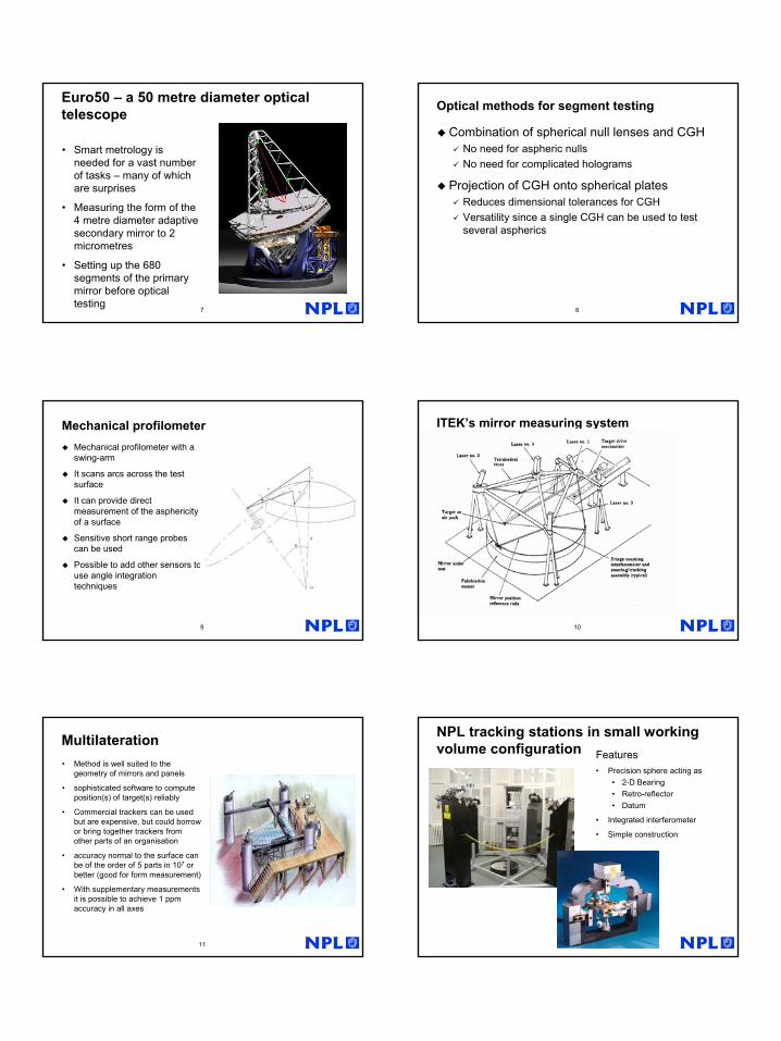
Dr. Peggs gave an overview of the conceptual designs, status, and measurement challenges associated with a new class of large, Earth-based optical telescopes. Two particular instruments were emphasized: the wonderfully named 100 m diameter Overwhelmingly Large Telescope (OWLT) and a somewhat more modest 50 m diameter instrument called the Euro50. These proposed devices are excellent examples of big, complex systems with integrated metrology needs, with the latter being partially driven by customer demands for traceable measurements.
Dr. Peggs reviewed the scientific drivers for next-generation telescopes: bigger apertures, better image quality, larger fields of view. He discussed the design and metrology tradeoffs between spherical and aspheric primary mirrors, and discussed the possible metrology approaches for optical figure metrology on large numbers (2000 in some designs) of primary mirror segments. Possible options include (a) null testing with some combination of spherical null lenses and computer-generated holograms; (b) a mechanical profilometer with a probe on a swing arm, and (c) a multilateration approach using multiple (typically four) laser trackers.
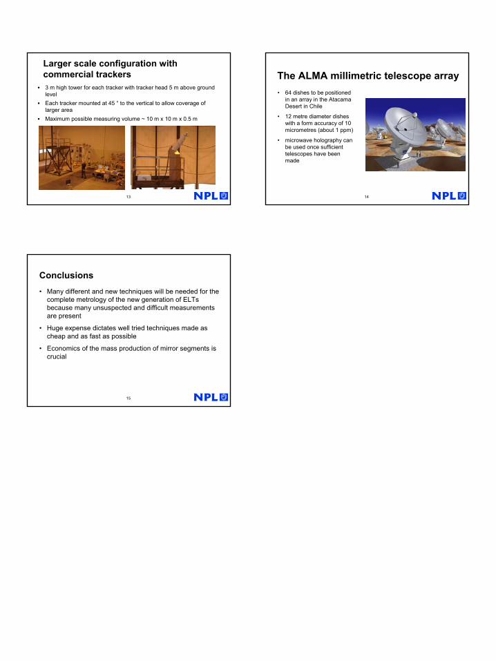
Dr. Peggs described current work on multilateration at NPL, where both a custom design and an arrangement of commercial instruments have been used with uncertainties near one part per million demonstrated.
Prof. Hocken recalled the early days of the Strategic Defense Initiative (SDI), and wondered whether there exists global production capacity to produce to area of optical glass required for these giant telescopes. Dr. Peggs agreed that current

5
capability is inadequate but opined that actual funding for such a telescope would bring production people ‘out of the woodwork.’
Prof. Hocken also wondered about who would fund such huge project with no foreseeable payback. Dr. Peggs speculated that large philanthropic funding sources might become available, similar to the donations that made the Keck telescope possible.
Dr. Evans wondered if atmospheric ‘seeing’ would place a practical limit on the size of the primary aperture. There was some discussion of adaptive optics, which would clearly be required, and the question arose about ground-based versus space-based optical astronomy. Would a 10 m space telescope be better than a 100 m ground-based instrument?
Prof. Schellekens asked about the type of adaptive optics being proposed. Exactly how is the optical wavefront correction to be done? Dr. Peggs replied that in the case of the Euro50 telescope, each of the 680 primary segments will be movable, and that the aspheric secondary mirror will be shape-corrected using some 7000 actuators. There was considerable discussion about active optics, and Prof. Schellekens suggested that we might invite an expert in the field to give a presentation at a future STC P meeting.
[A copy of Dr. Peggs’ presentation is attached as Annex 2.]
6.2 E. Savio – Validation of calibration procedures for freeform measurements on CMMs.
Dr. Savio stated that this project was carried out as a part of the European EASYTRAC program aimed at the development of uncertainty evaluation procedures for CMMs. The goal of the preset work is to generalize the use of uncalibrated workpieces in the evaluation of CMM measurement uncertainty to the measurement of freeform surfaces that are mathematically represented by CAD models.
The idea builds on the approach of ISO 15530-6, wherein an uncalibrated workpiece is repeatedly measured while the measurement conditions (point sampling strategy, workpiece position and orientation in the CMM working volume, thermal environment, etc) are varied. The measurement uncertainty can then be evaluated from the statistics of this ‘randomized’ data, with additional contributions from the uncertainties in the calibrated length standards used to link the measurement data with the realization of the SI meter.
This approach is generalized to the measurement of freeform surfaces represented by CAD models, with the measurands being local deviations of the actual surfaces from the CAD representation. The CAD model is used to generate a large sample of nominal target points. The actual positions of the measured points are used to recalculate the nominal measurement points so as to correct the measured deviations.
The procedure was applied to four components of industrial interest: a turbine blade, a modular freeform gauge, a screw compressor rotor, and a bevel gear electrode. Three CMMs have been used with their commercial software for part

6
measurement, and a separate external software module for the uncertainty analysis.
Typical data were shown from the measurements of the turbine blade on two CMMs – a high-accuracy machine and a more typical machine of lower accuracy. The results looked quite similar, with a lower expanded uncertainty U =2.9 µm for the high-accuracy CMM as compared with U = 6.2 µm for the lower accuracy CMM.
Dr. Savio noted on the data for measurements of the bevel gear with two CMMs that bad measuring conditions (such as erroneous programming or a bad probe setup) could be signaled by an abnormally high evaluated uncertainty.
In conclusion, Dr. Savio stated that the technique is suitable for freeform measurements without the need for calibrated artifacts of similar shape. He also emphasized that experiments suggested by this work can be very valuable to users in choosing an appropriate measurement strategy and providing information that can condition uncertainty assignment based on expert judgment.
Prof. Kruth asked for clarification on the definition of the quantity tTP that occurs in the measurement procedure. Dr. Savio explained that in general the actual measured points would differ from the programmed theoretical nominal points. The measurement data is then used to re-calculate the positions of these nominal points, and the parameter tTP is the maximum allowable distance between a target nominal point and a re-calculated nominal point, typically held to less than 0.05 mm.
Prof. Peters asked how long does it take to perform a complete measurement cycle. Dr. Savio replied that it depends on the number of points, but typically measuring a workpiece 15 times (5 repeats in each of 3 positions) takes about two days.
Prof. Wilhelm inquired as to the procedure used to choose the limit on tTP. There was a considerable discussion of this point that is difficult to summarize in these minutes. Interested parties are encouraged to correspond directly with Prof. Savio for further clarification.
[A copy of Dr. Savio’s presentation is attached as Annex 3.]
6.3 L. De Chiffre: Update on the small hole plate round robin.
Prof. De Chiffre began by thanking those participants who have submitted preliminary results. All of them have been interesting and additional results will be welcome. In particular there have been many useful comments on the practical aspects of the intercomparison.
An invitation has been circulated to all CIRP members, and Prof. De Chiffre showed a preliminary circulation time schedule calling for three hole plates to circulate among 15 participating laboratories (each plate to be measured by 5 participants.) The total exercise is envisaged to take 5 months (one month per participant, including shipping time.) The provisional schedule calls for beginning the measurements in March 2003 and finishing by August 1. All plates will be
7
measured at CGM in February, prior to beginning the circulation and again in August after the completion. Prof. De Chiffre hopes to have a preliminary report available by the time of the Montreal General Assembly.
Prof. De Chiffre stated that 9 mechanical and 9 optical machines were currently signed up, and that while the plates are really intended for use on optical machines it will be very useful to have the mechanical results as well. He described the proposed measurement procedure and reviewed the expected results. Prof. Hocken asked about the algorithm to be used to find the hole centers. Prof. De Chiffre replied that a detailed procedure including this information would come with the plates.
Dr. Kunzmann inquired as to the purpose of this round robin. Prof. De Chiffre replied that there are several motivations: collect information on the stability and performance of these hole plates as reference artifacts; an assessment of the state of the art in optical CMMs; to compare results from optical and mechanical measurements on the same artifact; and to provide information to the individual participants on the quality of their CMM measurements.
Dr. Kunzmann pointed out that with three different plates, 15 laboratories, and 18 machines of two quite different kinds, the question of data analysis in order to get the most useful results from the exercise is a very challenging one. He suggested that Maurice Cox from NPL might be a useful contact in this area.
Prof. Kruth remarked that the method of measurement would in general depend on what you expect to learn from the exercise. Prof. De Chiffre replied that the main objective is to assess the suitability of this type of hole plate as an artifact for testing optical CMMs.
Dr. Kunzmann said that it would be important to specify the illumination conditions when measuring with an optical CMM.
Prof. Pfeifer then displayed some interesting results comparing the performance of an optical CMM and a high-accuracy mechanical (Zeiss) CMM when measuring one of these hole plates. The results showed a quite good agreement, indicating that the plate should be useful for the evaluation of optical CMMs
7. Conferences and Seminars referring to STC "P"
• Prof. Hocken announced the ASPE Summer Topical Meeting on CMMs, to be held during 25-26 June 2003 at UNCC-Charlotte. He also announced the ASPE Annual Meeting, to be held during 26-31 October 2003 in Portland, Oregon. Detailed information about these meetings can be found at: www.aspe.net.
• Dr. Peggs and Prof. De Chiffre announced the CIRP Seminar on Micro and Nano Technology, which will take place during 13-14 November 2003 in Copenhagen, Denmark. Detailed information can be found at: www.cirpmicroengcph.dk.
• Dr. Peggs announced the LAMDAMAP 2003 International Conference, to be held during 1-4 July 2003 at the University of Huddersfield, UK. Details on this meeting can be found at: lamdamap.hud.ac.uk.
8
• Dr. Kunzmann announced the euspen International Topical Conference on Precision Engineering, Micro Technology and Measurement Techniques and Equipment, to be held during 19-21 May 2003 at Aachen, Germany. A brochure and registration form can be found at: http://www.euspen03.de/files/Flyer_1.pdf.
8. Round Table subjects for 2005 Prof. Hocken suggested the topic: The role of CIRP in nanotechnology. There were no further suggestions and this proposal was accepted.
9. Other business. Prof. Hocken reported that the CIRP President has asked him to organize a nanotechnology working group (as opposed to a paper session) at the Montreal General Assembly. He proposed replacing, on a one-time-only basis, both the CMM (sub P) and S (sub S) working groups with a special nanotechnology working group at Montreal. The purpose would be to assess where we (CIRP) are and where we might be going in the nanotechnology area.
Dr. Balsamo, who Chairs the CMM WG, said that while he was sure that there would certainly be items to cover regarding CMMs, he was not opposed to the idea. Prof. Hocken said, with respect to CMMs in particular, that one of the topics that he would like to see discussed is the use of ‘microCMMs’ for the measurement of MEMS devices, and that several groups around the world were working on such small CMMs. So in this sense, CMMs can be viewed as a part of nanotechnology.
Dr. Kunzmann expressed his strong support for the idea, and Dr. Peggs was also positive in his support. Dr. Kunzmann emphasized that CIRP cannot be involved in all aspects of nanotechnology but must focus on a part of it, recognizing the growing importance of physics and chemistry as parts get smaller and smaller.
Prof. Hocken agreed to go forward to the Liaison Committee with the proposal.
Prof. Goch called attention to the European Virtual Institute of Geometrical Measurements (EVIGeM), which has been up and running well since July 2002. This on-line consortium offers measurement services, expert mediation, education and training and other services to its members. For more information see: www.evigem.com.
Dr. Peggs asked the attendees to begin thinking about short technical presentations for the Montreal meeting and encouraged active participation.
10. Closure
Dr. Peggs thanked all of the participants and the meeting was adjourned.
11. Annexes 1. Outline of 2004 Plenary Session Keynote Paper by Prof. Weckenmann.
2. Viewgraphs of Dr. Peggs on very large optical telescopes.
3. Viewgraphs of Dr. Savio on freeform CMM measurements..

Keynote Paper P CIRP GA 2004
We / V03/05 / 25.01.2003
Probing Systems in Dimensional Metrology
A. Weckenmann, T. Estler, G. Peggs 1 Task of a probing system in CMM
1.1 General requirements; requirements on characteristic features 1.2 Requirements for different applications
2 Principles of probing (fundamental physical principles and characteristics
for applications) 2.1 Tactile (scanning/measuring – touch trigger, ranges of application) 2.2 Non-tactile (measuring systems – vision systems, image processing) 2.3 1D – 2D – 2 1/2D – 3D
3 Examples for realised probing systems and their performances
3.1 Renishaw touch trigger probe Triangulation system Zeiss-system (scanning and touch trigger)
3.2 Laser tracker 3.3 Fibre probing system
AFM/SPM Autofocus
4 Trends

1
1
CIRP Paris 2003
Large-scale, ultra-precision dimensional metrology for Extremely Large TelescopesGraham PeggsNational Physical Laboratory
Date: January 20032
Traceability for large telescopes
• Quality Management Systems demand traceable coordinate measurements
• Technically, size does not matter much, but shape does
• BUT, mirror production will take 5 years and the first segment must be the same as the last
3
Motivation – an astronomer wants:
Aperture: more signal
Image quality: less background, more detail
Field of view: more sky more objects
4
Why large optical telescopes?Astronomers really want to get:• spectroscopic information about
ever fainter celestial objects• Views of planets around nearby
stars• Discs around young stars• Processes around super-massive
black holes• Large scale structures in glactic
clusters
All these requirements imply a very large 30-100 metre diameter aperture adaptive optics-based telescope
5
Big, bigger, biggest
California Extremely Large Telescope (CELT-30 m)
Euro50 (50m)
Overwhelmingly Large Telescope (OWLT-100 m)
Giant Segmented Mirror Telescope (GSMT-30 m)
6
Spherical or aspherical optics? – the big debate
Spherical optical primaryGood for mass production of segments (2000) and testing of very long radius of curvature 250 metresOptically good at the 100 metre sizeComplex aspherical optics required for spherical aberration compensation30 metre diameter flat required for beam folding
Aspherical optical primaryMore compact designs possible – 2 mirrors 7 metre secondary“slightly” more complex to measure opticsMore families of optical components in the mirror
2
7
Euro50 – a 50 metre diameter optical telescope
• Smart metrology is needed for a vast number of tasks – many of which are surprises
• Measuring the form of the 4 metre diameter adaptive secondary mirror to 2 micrometres
• Setting up the 680 segments of the primary mirror before optical testing
8
Optical methods for segment testing
Combination of spherical null lenses and CGHNo need for aspheric nullsNo need for complicated holograms
Projection of CGH onto spherical platesReduces dimensional tolerances for CGHVersatility since a single CGH can be used to test several aspherics
9
Mechanical profilometerMechanical profilometer with a swing-arm
It scans arcs across the test surface
It can provide direct measurement of the asphericityof a surface
Sensitive short range probes can be used
Possible to add other sensors to use angle integration techniques
10
ITEK’s mirror measuring system
11
Multilateration• Method is well suited to the
geometry of mirrors and panels
• sophisticated software to compute position(s) of target(s) reliably
• Commercial trackers can be used but are expensive, but could borrow or bring together trackers from other parts of an organisation
• accuracy normal to the surface can be of the order of 5 parts in 107 or better (good for form measurement)
• With supplementary measurements it is possible to achieve 1 ppm accuracy in all axes
12
NPL tracking stations in small working volume configuration Features
• Precision sphere acting as• 2-D Bearing• Retro-reflector• Datum
• Integrated interferometer
• Simple construction
3
13
3 m high tower for each tracker with tracker head 5 m above ground levelEach tracker mounted at 45 ° to the vertical to allow coverage of larger areaMaximum possible measuring volume ~ 10 m x 10 m x 0.5 m
Larger scale configuration with commercial trackers
14
The ALMA millimetric telescope array• 64 dishes to be positioned
in an array in the AtacamaDesert in Chile
• 12 metre diameter dishes with a form accuracy of 10 micrometres (about 1 ppm)
• microwave holography can be used once sufficient telescopes have been made
15
Conclusions• Many different and new techniques will be needed for the
complete metrology of the new generation of ELTs because many unsuspected and difficult measurements are present
• Huge expense dictates well tried techniques made as cheap and as fast as possible
• Economics of the mass production of mirror segments is crucial

1
Università di PadovaEnrico SAVIO
Validation of calibration procedures for freeform measurements on CMMs
CIRP STC “P” Paris, January 2003
Outline
Approach to uncertainty assessment
Calibration procedure for freeform inspection
Experiments on industrial components
1. Turbine blade
2. Modular Freeform Gauge
3. Screw compressor rotor
4. Bevel gear
Comparison of uncertainty statements
Conclusions
Università di PadovaEnrico SAVIO
Validation of calibration procedures for freeform measurements on CMMs
CIRP STC “P” Paris, January 2003
Measurements of a (similar) uncalibrated object, with varying measuring conditions
M1) different distributions of points and reduced scanning speed (repeatability, part form errors, temp. variations, sampling, ...) urep
M2) workpiece orientation (CMM geometric errors, clamping, probe tip influences, ..) ugeo
Measurements of calibrated length and form standards
M3) average scale factor error (length meas. capability) Elength
M4) form test (form meas. capability)
XWP
YWP
ZWP
XWP
YWP
XWP
YWP
XWP
ZWP
ZWP
Basic position
ZWP
YWP
XWP
YWP
ZWP
XWP
YWP
XWP
YWP
XWP
ZWP
ZWP
Basic position
ZWP
YWP
YWP
ZWP
XWP
YWP
XWP
YWP
XWP
ZWP
XWP
ZWP
ZWP
Basic position
ZWP
YWP
Uncalibrated Workpieces & Multiple Strategiesworking draft ISO 15530-6
Approach
min 3 orthogonal orientation
Università di PadovaEnrico SAVIO
Validation of calibration procedures for freeform measurements on CMMs
CIRP STC “P” Paris, January 2003
Inspection of freeform surfacesProcedure
Meas. task: set of target CAD points
Measurand: local deviations from CAD model
Measuring mode: contact scanning
Control of tip positioning accuracy
target nominal point
actualmeasured point
theoreticalprobingdirection
CMM probe
CAD
nominal point(recalculated)
Partdistance between
target nominal point and recalculated nominal point
≤ tTP
Università di PadovaEnrico SAVIO
Validation of calibration procedures for freeform measurements on CMMs
CIRP STC “P” Paris, January 2003
Plan of calibrations
XXplannedBevel gear electrode4XXScrew compressor rotor3
XModular freeform gauge2
CMM3
X XX XTurbine blade1
CMM2CMM1WORKPIECEN.
Experiments
using : typical industrial freeform workpieces (thousands of points)commercial CMM measuring softwareexternal software module for uncertainty calculations
Università di PadovaEnrico SAVIO
Validation of calibration procedures for freeform measurements on CMMs
CIRP STC “P” Paris, January 2003
Master turbine blade
Measurands:local deviations from CAD model, 9 sections, approx. 8200 points
Experiment 1
target nominal points (0.2 mm spacing)
Università di PadovaEnrico SAVIO
Validation of calibration procedures for freeform measurements on CMMs
CIRP STC “P” Paris, January 2003
Master turbine bladeComparison 1
CMM1 - data 1 4MPEE 0.4+L/900 µm
UFF ≅ 2.9 µm
CMM 2 - data 2 3 MPEE 2.2+L/300 µm
UFF ≅ 6.2 µm
Section 5, detail – unfiltered [mm]
target nominal points (0.2 mm spacing)

2
Università di PadovaEnrico SAVIO
Validation of calibration procedures for freeform measurements on CMMs
CIRP STC “P” Paris, January 2003
Modular Freeform Gauge(ISO 15530-3 procedure)
0
1
2
3
1 2 3 4 5 6 7 8 9section
Estim
ated
unc
erta
inty
(k=2
) [µ
m]
max abs. local deviation, CMM1
Experiment 2
Università di PadovaEnrico SAVIO
Validation of calibration procedures for freeform measurements on CMMs
CIRP STC “P” Paris, January 2003
Screw compressor rotorExperiment 3
Inspection of freeform profile Measurands:local deviations from CAD model, median section, approx. 6000 points)
Università di PadovaEnrico SAVIO
Validation of calibration procedures for freeform measurements on CMMs
CIRP STC “P” Paris, January 2003
Screw compressor rotorComparison 3
-0.004
-0.002
0.000
0.002
0.004
0.006
0.008
0.010
0.012
measuring points
loca
l dev
iatio
n fr
om C
AD
mod
el [m
m]
CMM 1 MPEE 0.4+L/900 µm
UFF ≅ 2.4 µm
CMM 2MPEE 2.2+L/300 µm
UFF ≅ 4 µm
Profile portion, gap 1-2 (60°) - unfiltered
Università di PadovaEnrico SAVIO
Validation of calibration procedures for freeform measurements on CMMs
CIRP STC “P” Paris, January 2003
1 2
3
4
5
6
Bevel gear electrode
Measurands:local deviations from CAD model, 9 sections on 6 teeth , approx. 1000 points
Experiment 4
target nominal scan lines
Università di PadovaEnrico SAVIO
Validation of calibration procedures for freeform measurements on CMMs
CIRP STC “P” Paris, January 2003
Bevel gearComparison 4
CMM 3 - data 2MPEE 2.0+L/300 µm(tTP = 0.2 mmbad probe setup)
UFF ≅ 25 µm
CMM 2 - data1MPEE 2.2+L/300 µm(tTP =0.03 mm)
UFF ≅ 5 µm
Detail of tooth profiles – unfiltered
target nominal points
-
-
loca
l dev
iatio
n fr
om C
AD
mod
el [m
m]
Università di PadovaEnrico SAVIO
Validation of calibration procedures for freeform measurements on CMMs
CIRP STC “P” Paris, January 2003
Conclusions
no calibrated objects with similarity requirements are needed !
(of course, calibrated length and form standards are still required)
suitable for freeform measurements
suggested experiments are very useful to USERS: it is a guided procedure to
understand and quantify the effect of different strategies (distribution of
points, scanning speed, workpiece orientation, probe configuration, etc)
can provide data for uncertainty estimation based on “expert judgement”can help the user to select the “best” measurement setup
WARNING:
overestimation of ugeo (CMM geom. errors) when positioning in unusual
orientations, and/or bad measurement conditions
Conclusions


![PACMAN Project World Metrology Day - NCSL … Metrology Day 20 May 2016 PACMAN Project. Outline ... precision mechanics @ nano-positioning [Michele Modena] ... Prove their feasibility](https://static.fdocuments.us/doc/165x107/5ae9c28f7f8b9ae5318b8681/pacman-project-world-metrology-day-ncsl-metrology-day-20-may-2016-pacman-project.jpg)