STC 361 - 1300 - Berco - Sottocarro · - from grinding wheel to tool: 1 ... machines for the...
8
Hydraulic grinding milling machine for cylinder heads and blocks STC 361 - 1300 A Company of ThyssenKrupp BERCO S.p.A.
Transcript of STC 361 - 1300 - Berco - Sottocarro · - from grinding wheel to tool: 1 ... machines for the...
Hydraulic grindingmilling machine for cylinder heads and blocks
STC 361 - 1300
A Company
of ThyssenKrupp
BERCO S.p.A.

General view of the machine withsliding doors protection inaccordance to “CE” regulation.Inset
- from grinding wheel to tool: 1’
- from tool to milling cutter: 3’
These are the tool changeover
times required to pass from one
machining method to another.
The machine and its executions
General view of the standardmachine version.
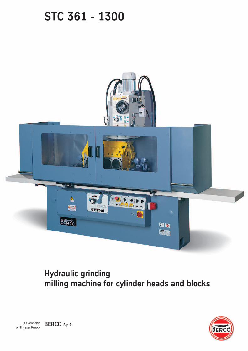
The STC 361 is the range of
hydraulic grinding/milling
machines for the reconditioning
of mating surfaces on small
and medium sized cylinder
heads and blocks which Berco,
who supply machine tools in
this sector worldwide, are now
making available to users.
Compared to the previous very
popular range of
grinding/milling machines, the
STC 361 series offers greater
reliability, even further
improved operating precision
and more practical, safer
operation.
The STC 361 range are simple,
versatile machines able to meet
the requirements of large and
small workshops alike, since
they provide an excellent,
economical solution to all
grinding/milling problems.
They can operate: with
segmental wheel for grinding
materials of all kinds; with
single-point tool for cutting
aluminium and, on request,
with a multi-edged insert
milling cutter for rapid cutting
of cast iron and aluminium.
The special feature of the STC361machines is the automatic,
hydraulically powered
alternating table traverse.
They are available with table
working traverse 1300 mm
(51”), and can be ordered in
versions “C-E” which vary, as
explained forward, in
component assemblies and
operating procedures.
A few features of this new line
of grinding and milling
machines:
Controls. These are all on thefront of the machine,
conveniently positioned for
checks and handling.
Table. Runs on automatically
lubricated flat and V-shaped
ways. Controlled by a lever for
manual and automatic reverse
and a knob providing the STOP
function and traverse speed
selection. The table runs
without “stick-slip” problems
even at very low speeds.
Wheelhead. Driven by a highpowered main motor driving the
wheel holder shaft directly, an
auxiliary motor for the milling
cutter and a handwheel with
adjustable graded ring for
controlled cutting depth setting.
Cooling system. The coolant
tank, separate from the
machine, is complete with
wheels for easy transfer to the
emptying, cleaning and filling
site.
Electrics. Complete with main
switch fitted for padlocking,
emergency pushbutton and
devices providing protection
against power failure.
Resurfacing methods.Depending on the material and
the level of finishing required,
there are three different
machining procedures
available: using grinding wheel,
single-point cutter and multi-
edged insert milling cutter.
It takes just a few minutes to
change from one system to
another, since both the single-
point cutter and the milling
cutter are mounted directly on
the wheel holder ring.
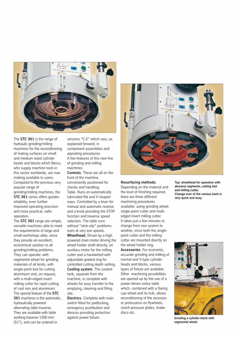
Accessories. For economic,
accurate grinding and milling of
normal and V-type cylinder
heads and blocks, various
types of fixture are available.
Other machining possibilities
are opened up by the use of a
power-driven rotary table
which, combined with a flaring
cup wheel and its hub, allows
reconditioning of the recesses
or protrusions on flywheels,
clutch pressure plates, brake
discs etc.
Grinding a cylinder block withsegmental wheel.
Top: wheelhead for operation withabrasive segments, cutting tooland milling cutter.Change-over of the various tools isvery quick and easy.
All the versions are available with variable spindle speed.
Version CMachine with 2 spindle shaft rotation speeds for processing with
segmental grinding wheel and single-point tool, and with power- driven
head traverse.
Version EMachine having the same technical features and applications as version
“C” with adjustable automatic head feed at each return table traverse,
and 3 spindle shaft rotation.
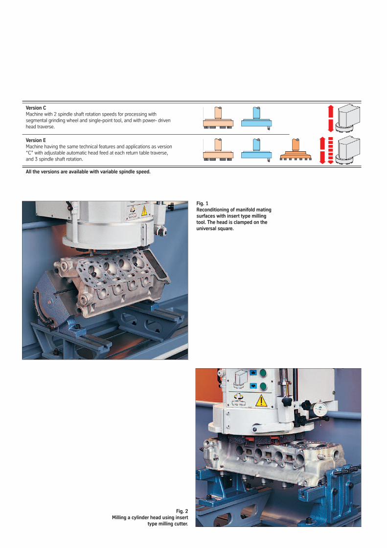
Fig. 1Reconditioning of manifold matingsurfaces with insert type millingtool. The head is clamped on theuniversal square.
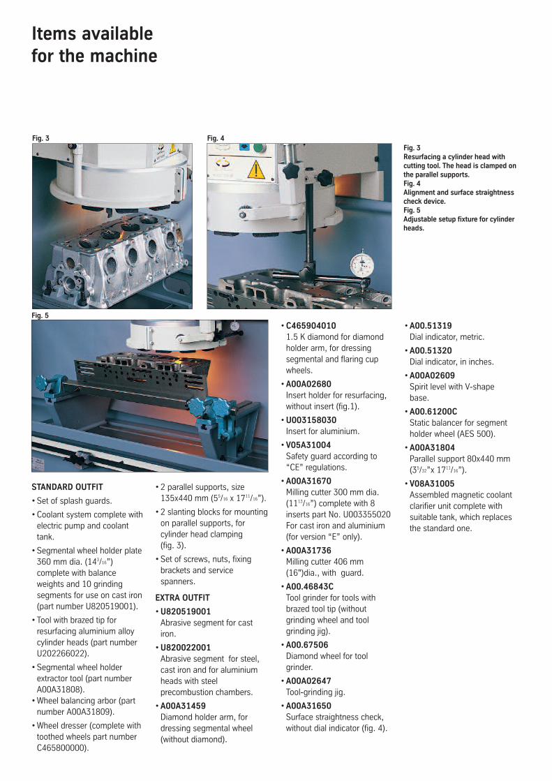
Fig. 2Milling a cylinder head using insert
type milling cutter.
Items availablefor the machine
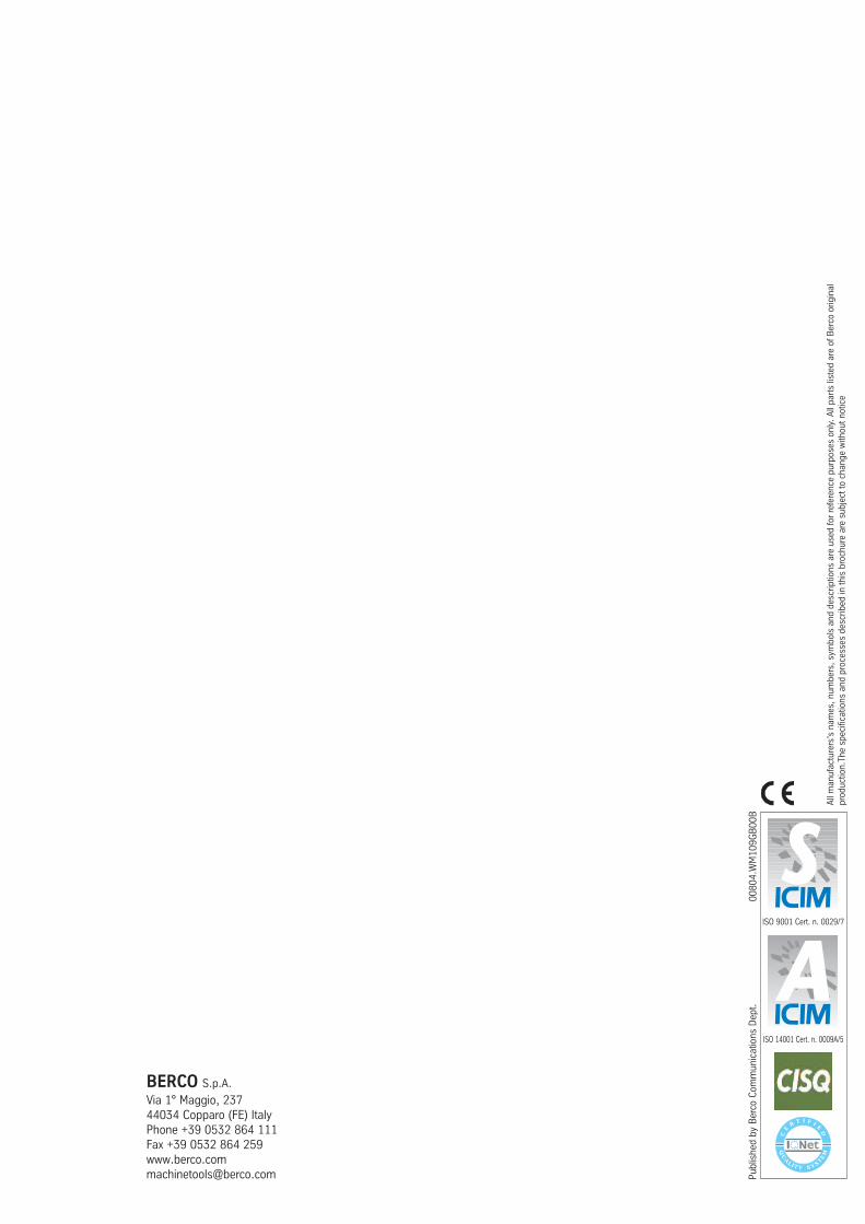
Fig. 3Resurfacing a cylinder head withcutting tool. The head is clamped onthe parallel supports.Fig. 4Alignment and surface straightnesscheck device.Fig. 5Adjustable setup fixture for cylinderheads.
Fig. 3
Fig. 5
Fig. 4
STANDARD OUTFIT
• Set of splash guards.
• Coolant system complete with
electric pump and coolant
tank.
• Segmental wheel holder plate
360 mm dia. (14
3
/
16
”)
complete with balance
weights and 10 grinding
segments for use on cast iron
(part number U820519001).
• Tool with brazed tip for
resurfacing aluminium alloy
cylinder heads (part number
U202266022).
• Segmental wheel holder
extractor tool (part number
A00A31808).
•Wheel balancing arbor (part
number A00A31809).
•Wheel dresser (complete with
toothed wheels part number
C465800000).
• 2 parallel supports, size
135x440 mm (5
5
/
16
x 17
11
/
16
”).
• 2 slanting blocks for mounting
on parallel supports, for
cylinder head clamping
(fig. 3).
• Set of screws, nuts, fixing
brackets and service
spanners.
EXTRA OUTFIT
•U820519001Abrasive segment for cast
iron.
•U820022001Abrasive segment for steel,
cast iron and for aluminium
heads with steel
precombustion chambers.
•A00A31459Diamond holder arm, for
dressing segmental wheel
(without diamond).
•C4659040101.5 K diamond for diamond
holder arm, for dressing
segmental and flaring cup
wheels.
•A00A02680Insert holder for resurfacing,
without insert (fig.1).
•U003158030Insert for aluminium.
•V05A31004Safety guard according to
“CE” regulations.
•A00A31670Milling cutter 300 mm dia.
(11
13
/
16
”) complete with 8
inserts part No. U003355020
For cast iron and aluminium
(for version “E” only).
•A00A31736Milling cutter 406 mm
(16")dia., with guard.
•A00.46843CTool grinder for tools with
brazed tool tip (without
grinding wheel and tool
grinding jig).
•A00.67506Diamond wheel for tool
grinder.
•A00A02647Tool-grinding jig.
•A00A31650Surface straightness check,
without dial indicator (fig. 4).
•A00.51319Dial indicator, metric.
•A00.51320Dial indicator, in inches.
•A00A02609Spirit level with V-shape
base.
•A00.61200CStatic balancer for segment
holder wheel (AES 500).
•A00A31804Parallel support 80x440 mm
(3
5
/
32
”x 17
11
/
16
”).
•V08A31005Assembled magnetic coolant
clarifier unit complete with
suitable tank, which replaces
the standard one.

Figs. 6-7Rotary table used for grinding therecesses of a flywheel and a clutchplate.Fig. 8Grinding some mechanicalcomponents with permanentmagnet chuck. Fig. 9Adjustable setup fixture for V-blocks.
Fig. 6 Fig. 7
Fig. 8
Special processing accessories
•P02A31700Power-driven rotary table
(TR 1) for grinding flywheels,
clutch pressure plates and
brake discs (12 rpm - 0.2 kW)
(figs.6-7).
•A00A25651Tooling for centering and
clamping clutch pressure
plates with diaphram type
springs onto the rotaty table.
•A00A25652Set of screws and plates for
clamping brake discs and
flywheels onto the rotary table.
Cylinder head and block setup fixtures
•A01.32433Adjustable setup fixture for
clamping V-type cylinder
heads and blocks (figs.5-8).
•A00.41731AUniversal cylinder head setup
square (fig. 1).
•A00A02600Parallel support for cylinder
heads complete with plate and
lock screws (2 pieces required)
(fig. 2).
• Other setup fixtures available
on request.
•A00A31692Wheel holder complete with
flaring cup wheel for cast iron
(part No. U814511020)
127 dia.x36x64 mm
(5”x1
13
/
32
”x2
17
/
32
”) for use with
rotary table.
•U814111101Flaring cup wheel for steel
127 dia.x36 x64 mm
(5”x1
13
/
32
”x2
17
/
32
”).
•A00A31691Diamond holder arm for
dressing flaring cup wheel
(without diamond).
Fig. 9
•C150710020Magnetic chuck 500x250 mm
(1911/16”x9
27
/
32
”).
•C150710000Magnetic chuck 610x250 mm
(24”x9
27
/
32
”) (fig.9).
•C150710010Magnetic chuck 800x300 mm
(31
1
/
2
”x11
13
/
16
”).
All setup fixtures and
accessories are supplied as
extra outfit.

Technical data
Operating capacityMax. automatic table traverse mm 1300 (51”)
Vertical wheelhead traverse mm 680 (263/4”)
Max. grinding width mm 350 (133/4”)
Max. grinding length on wide surface 280 mm (11”) mm 1200 (47”)
Max. milling width with cutting tool mm 330 (13”)
Geometric featuresUseful table surface mm 1220x280 (48x11”)
Min. and max. height table to wheel mm 0-700 (0-279/16”)
Min. and max. height table to tool or milling cutter mm 0-670 (0-263/8”)
Distance from column to table C/L mm 280 (11”)
Segmental wheel diameter mm 360 (143/16”)
Multi-edged insert milling cutter diameter
(version “E” only) mm 300 (1113/16”)
Speeds and feedsSpindle rotation speeds (2) rpm 1400 and 700
Spindle rotation speeds (stepless) “VS” version rpm 200÷1900
Milling rotating speed
(version “E” only) rpm 140
Rapid wheelhead feed speed mm/min. 660 (26”)
Min. and max. table traverse feed speed
(stepless), mm/min. 100-4000 (4”-157”)
Motor ratingsGrinding and single-point
cutting tool spindle kW 3.6/0.6 (5/0.8 HP)
Milling cutter spindle (version “E” only) kW 0.55 (0.75 HP)
Rapid vertical wheelhead traverse (versions “C” - “E” only) kW 0.24 (0.33 HP)
Hydraulic system kW 0.37 (0.5 HP)
Electric coolant pump kW 0.09 (0.12 HP)
Dimensions and weightsLength A mm 4500 (177”)
Width B mm 970 (38”)
Height C mm 2160 (85”)
Approx. weight, unpacked kg 1220 (2690 lb)
Approx. weight, ocean packed kg 1610 (3564 lb)
Motor rating is referred to 50 Hz frequency. Measurements, weights and executions are not binding on manufacturers and can be changed without previous notice.
BERCO S.p.A.
Via 1° Maggio, 237
44034 Copparo (FE) Italy
Phone +39 0532 864 111
Fax +39 0532 864 259
www.berco.com
00804.WM109GB00B
Published by Berco Communications Dept.
ISO 9001 Cert. n. 0029/7
ISO 14001 Cert. n. 0009A/5
All manufacturers’s names, numbers, symbols and descriptions are used for reference purposes only. All parts listed are of Berco original
production.The specifications and processes described in this brochure are subject to change without notice