Stay-In-Place Formwork
110
Stay-In-Place Formwork Dr. N. Gopalakrishnan Director CSIR-Central Building Research Institute, Roorkee-247667, Uttarakhand, India
Transcript of Stay-In-Place Formwork

Stay-In-Place Formwork
Dr. N. GopalakrishnanDirector
CSIR-Central Building Research Institute,
Roorkee-247667,
Uttarakhand, India

Formwork in Construction
1
2
4

Importance of Formwork

Limitations
1. Wood, steel sheets/plates, ply boards, Aluminum, Plastics etc… are com
monly used form work materials.
2. Formwork costs around 40-50% of the total construction cost in RCC.
3. Storing and limitations in reusing increases the capital investment in con
struction industry.
4. Formwork arrangement and its alignment consumes more time compare
d to the concreting work.
5. Aluminum form work, steel form work, vinyl based form work, rubber and
glass form works are also available. But still the capital investments are
high and requires maintenance, transportation, storing unit etc..

NEED OF STAY-IN-PLACE FORM WORK
Stay in place (SIP) form work system is an effective and advanced way of
formwork system.
In SIP the formwork material become an integral part of the structural ele
ments Advantages such as thermal comfort, external protection to resist
the durability issues, additional confining pressure and reduces the
construction time and offers viable economical solution.
Different materials such as fibers reinforced polymers (FRP), polyvinyl
(PVC), Cementitious composites, extended polystyrene (EPS), glass fiber
reinforced concrete/composites (GFRP), steel composites, steel meshes
etc... have been in practice.

Research Scope in SIP
Numerous researches have focused on improving the SIP system m
ore systematically and efficiently. Problems such as the bond
between the fresh concrete and the form work materials influence
on the elemental behavior, failure pattern, life span etc… have been
identified as issues in SIP systems and research level and practical
level solutions also had been proposed.

INSULATED CONCRETE FORMS (ICF)

Advantages
• Offers resistance to gravity and lateral loading due to its monolith
ic construction technique.
• Energy efficiency and thermal comfort
• Noise reduction
• Resistant to corrosion.
• Easy to install and time saving construction technique.
• Cost effective solution.

LATTICE BASED ICF SYSTEM AND ITS DIFFERENT MODULES

Structural SIP system

PVC Based SIP system


PVC Profile – Concrete Filler - SIP system

FRP BASED SIP FORM WORK SYSTEM


Structural Behavior of FRP SIP

FRP panel with Sand blast coating
Placing of FRP Planks between the girders

HYBRID FRP PANELS
In Hybrid FRP panels light weight concrete/foam based concrete used as cor
e material over a thin layer of normal concrete will be used. Figure shows the
Hybrid FRP panels. The bottom most FRP planks are offering better resistan
ce to tension and the top most concrete layer offers resistance to compressio
n. The inner core resists the shear force and acts as insulated materials. This
principle increases the stiffness and strength without increasing the density o
f the elements.

FRP Box Beam with Concrete in the Compression Zone
GFRP-concrete hybrid flexural member (Deskovic et al. 1995)
Concrete-filled FRP tubes with a concrete slab on top
(Fam and Skutezky, 2006)


Structural Behavior of Column Constructed using FRP SIP Formwork


T-up Stiffeners on Plate
Tubular Sections on Plate
FRP Grid Bonded to a Plate
Ribbed Plate
Dual Cavity System
Corrugated Plate Formwork
Common Detailing used in FRP SIP System

Octaform cell


Failure Pattern Failure Pattern
Test Setup
Specimen Details

SIP - Textile Reinforced Concrete

Internal Stress and Strain Distributions of RC Element casted on TRC -SIP


Lateral Pressure on Wall Formwork
[150 9000 / ]m w cP C C R T
lateral pressure for wall having the placement height less than or equal to 14
ft having rate of placement less than 7ft/hr.
Pm = maximum lateral pressure, lb/sqft
Cw = unit weight coefficient
Cc = chemistry coefficient
R = rate of fill of concrete in form, ft/hr
T = temperature of concrete in form, °F

For all wall forms with concrete placement rate from 7 to 15 ft/hr, and for
walls where the placement rate is less than 7 ft/hr and the placement height
exceeds 14 ft.
[150 43400 / 2800 / ]m w cP C C T R T

Thank you

Outline of Presentation
1
2
3
Steady and unsteady Heat Flow through Buildings
1
Mean temperature in the space
Temperature Monitoring in Building-A case Study
ECBC Codal Provisions & expt. Evaluation
Thermal Admittance and decrement factor
Fluctuating Heat gains and Internal temperature4
5
6
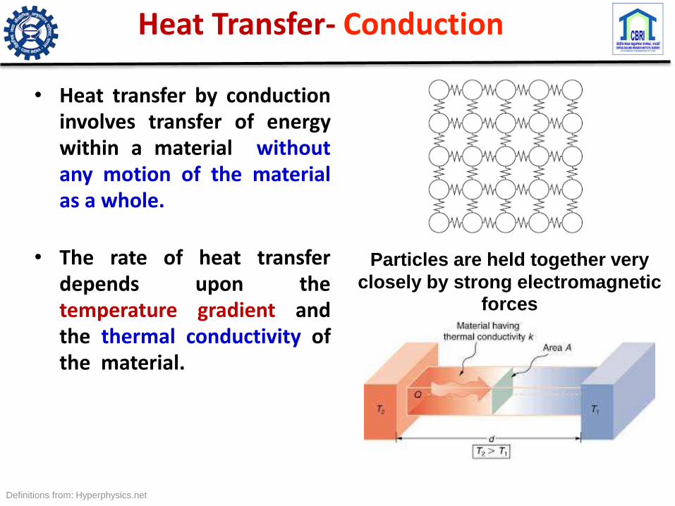
Heat Transfer- Conduction
• Heat transfer by conductioninvolves transfer of energywithin a material withoutany motion of the materialas a whole.
• The rate of heat transferdepends upon thetemperature gradient andthe thermal conductivity ofthe material.
Definitions from: Hyperphysics.net
Particles are held together very
closely by strong electromagnetic forces

• Heat transfer by mass motion of a fluid such as air or waterwhen the heated fluid is caused to move away from the sourceof heat, carrying energy with it.
• Convection above a hot surface occurs because hot airexpands, becomes less dense. Hot water is likewise less densethan cold water and rises, causing convection currents whichtransport energy.
Heat Transfer-Convection
Definition and diagram from: http://hyperphysics.phy-astr.gsu.edu/hbase/thermo/heatra.html#c3
Particles are quite
close to each other
and irregularly
connected
by weak
electromagnetic
forces that are
easily broken and
re-established.

Radiation is heat transfer by the emission ofelectromagnetic waves which carry energy away fromthe emitting object.
Heat Transfer- Radiation
Definition and diagram from: http://hyperphysics.phy-astr.gsu.edu/hbase/thermo/heatra.html#c3
There are no forces between them
except for occasional collisions.
They move around freely and
quickly.

Qs- Direct Solar radiation
Qc- heat flow through Conduction
Qv- Heat flow through Ventilation
Qi- heat generated through body, equipment’s
Qe- Heat Evaporation/emission during night
.
Heat Flow through Building Envelope

Qs- Direct Solar radiation
Qe- Heat Emission during night
Qc- heat flow through Conduction
Qv- Heat flow through ventilation
Qi- heat generated through body, equipment's..
Heat Flow through Building Envelope

Heat Flow Path
• Steady state: Temperature is constant at any time
• Transient Conduction/Dynamic /non-steady State)- Temperature at any location in a region changes with time

HEAT CONDUCTION THROUGH A PLANE WALL
Let us consider a plane wall of homogeneous material through which heat is flowing in x-direction.,
Let,
L = thickness of the wall
A = cross-sectional area of the wall
k = thermal conductivity of wall material
T0 ,T1 = temperature maintained at
surfaces 1 and 2.
ΔT- Temp difference inside and outside
𝛼 - Thermal diffusivity

HEAT CONDUCTION THROUGH A PLANE WALL
General heat conduction equation is:, (Fourier-Biot equation)
𝜕2𝑇/𝜕𝑥2 + 𝜕 2 𝑇 /𝜕𝑦2 +𝜕 2 𝑇/𝜕𝑧2 + 𝑞/𝑘 = 1/𝛼*𝜕𝑇/𝜕𝑡
For one dimensional steady state system (𝜕𝑇/𝜕𝑡) = 0
With no heat generation (q/k)= 0
One dimensional flow , 𝜕 2 𝑇 /𝜕𝑦2 =𝜕 2 𝑇/𝜕𝑧2= 0
Then, heat equation will be 𝜕 2 𝑇/𝜕𝑥2 = 0
𝑑 2 𝑇/𝑑𝑥2 = 0
Integrating above equation,
𝑑𝑇/𝑑𝑥 = C1
Integrating it again,
T= C1x +C2
Where C1 and C2 are arbitrary constants

Steady Heat Flow through wall
• At x = 0; T = T0
• At x = L; T = T1
From the expression derived above T = C1.x + C2 …………(1)
At x = 0;
T0 = C1 (0)+ C2
C2 = T0
At x = L;
T1 = C1 . L + T0
C1 = (T1 - T0 )/L
Eqn. 1 can be re-written as
T = ( 𝑻𝟏−𝑻𝟎/𝑳) . 𝒙 + T0
i.e temperature varies linearly with x

• Inference:
1. Temperature distribution across the wall is linear.
2. Temperature distribution is independent of k.
From Fourier’s Law of heat conduction, we have,
Heat flow Q = -k A𝑑𝑇/𝑑𝑥
𝑑𝑇/𝑑𝑥 = d/𝑑𝑥 ((T1-To )/L * 𝑥) + To) = (T1-To )/L
Fourier’s Law can be re-written as,
Q = -k A (T1-To )/L
Q = - A U (T1-To )
Where, k- Thermal Conductivity W/mk
L/kA = Thermal Resistance of heat conduction (R) = (L/kA)
U- Thermal Transmittance, W/m2K =1/R
Steady Heat Flow through wall

Steady Heat Flow through layered wall
Q = 𝒌𝟏𝑨(𝑻𝟏−𝑻𝟐)
𝒍𝟏= 𝒌𝟐𝑨
(𝑻𝟐−𝑻𝟑)
𝒍𝟐= ………..
𝑻𝟏 − 𝑻𝟐 + 𝑻𝟐 − 𝑻𝟑……..𝑻𝒏 = Q/A [𝒍𝟏/𝒌𝟏+ 𝒍𝟐/𝒌𝟐+….. 𝒍𝒏−𝟏/𝒌𝒏−𝟏]
𝑻𝟏 − 𝑻𝒏 = (Q/A)x R
R = 𝑹𝟏 + 𝑹𝟐+……
Layers may include cavity or insulation. Cavity R is used

Steady Heat Flow through layered wall
Q = 𝒉𝒐 𝑨 (𝑻𝒐𝒂 − 𝑻𝒐) = 𝒉𝒊 𝑨 (𝑻𝒊 − 𝑻𝒊𝒂)= (1/R) x (𝑻𝒐 − 𝑻𝒊) A
1/U = 1/𝒉𝒐 + 𝒍𝟏/ 𝒌𝟏 + 𝒍𝟐/ 𝒌𝟐+. . 𝒍𝒏−𝟏/ 𝒌𝒏−𝟏 + 1/ 𝒉𝒊
Q = UA∆T
U- Thermal Transmittance, W/m2K𝒉𝒐 and 𝒉𝒊 - Surface heat transfer coefficients

Steady Heat Flow through wall
Q = [𝑼𝟏𝑨𝟏 + 𝑼𝟐𝑨𝟐 … ](𝑻𝒐𝒂 − 𝑻𝒊𝒂)
UA = [𝑼𝟏𝑨𝟏 + 𝑼𝟐𝑨𝟐 … ]
Different surfaces are exposed same temperature gradient

External and Internal Temperature
Due to periodic nature the temperature can be expressed as a mean temperature and a fluctuating component.
i.e. 𝑇𝑜𝑎 (t) = 𝑇𝑜𝑎 + fluctuation
&𝑇𝑖𝑎 (t) = 𝑇𝑖𝑎 + fluctuation

Steady Heat Flow
• For conducting in steady state, heat exchange (𝑄𝑐𝑑)
𝑄𝑐𝑑 = ∑𝑈𝑗𝐴𝑗 (𝑇𝑜𝑎- 𝑇𝑖𝑎)

Effect of Radiation on opaque surface
• For unit area, heat absorbed by a surface = α l
After reaching steady state temperature (say at equivalent temperature toe),
The Heat Absorbed = Heat Dissipated
• i.e. α l =ℎ𝑜(𝑇𝑜𝑒- 𝑇𝑜𝑎)
α l /ℎ𝑜= Sol- air excess
𝑇𝑜𝑒= 𝑇𝑜𝑎 + α l /ℎ𝑜
α = Absorptivity of surface
𝑇𝑜𝑒= Sol-air temperature
𝑇𝑜𝑎 = Outside air temperature
ho= surface heat transfer coefficient

Temperature Gradient at different times
In (a)Temperature within the system does vary with time
In (b-d) Due to heat storage capacity of material Unsteady flow occur

Unsteady Heat Flow through wall
a) Light wall b) Heavy wall
TL: Time lag & Swing depends on thermal capacity i.e., Density x Specific heat
Thermal Mass
• Thermal mass is a term used in solar passive design todescribe materials that have the ability to absorb and storeheat.
• Solar efficient homes incorporate thermal mass in order toremain warm overnight and through periods of cold or cloudyweather
• High density materials such concrete, bricks, and tiles requirea great deal of heat energy to change their temperature andare therefore said to have high thermal mass. Lightweightmaterials, on the other hand, such timber, have low thermalmass.

Time Lag ø and Decrement factor f
Important characteristicsto determine the heatstorage capabilities ofany materialThe time (hour, h) ittakes for the heat waveto propagate from theouter surface to the innersurface is named as‘‘time lag (ø)’’ and thedecreasing ratio of itsamplitude during isnamed as ‘‘decrementfactor (f)
Where, t Tmax o time in hours when inside surface temperatures are at their maximums,
T Tmax e (h) time in hours when outside surface temperatures are at their maximumsP (24 h) is the period of the wave
Source: H Asan (2006)

Time Lag ø and Decrement factor f
The time lag may be computed as follows
The decrement factor is defined as:
Where, Ao, Ae amplitudes of the wave in the inner & outer surfaces of the wall
Smaller the decrement factor, the more effective is the envelope at suppressing temperature swings.
The time lag of the heat wave should be as high as possible to delay an outside sinusoidal heat wave from entering into the room
through the wall or roof.

Thermal Performance
• Effect of radiation on opaque surface is taken accountof through an equivalent temperature
• Short wave absorptivity (Low) and long wave emissivity(High) are also important
• Sequence of layer does not influence steady flowalthough may have effect in periodic heat flow

Layer
Conduction
Dynamic
Steady-State
U- value
Response Function
Numerical
Time domain
Frequency domain
Finite difference
Finite element
Boundary element
Heat Flow through Building

Harmonics

Frequency Domain Treatment

Frequency Domain Treatment
𝒂𝒋, bj can be determined by multiplying cos 𝟐𝝅𝒋𝒕
𝒑and sin
𝟐𝝅𝒋𝒕
𝒑
𝒂𝒋 =𝟐
𝒑
−𝒑/𝟐
𝒑/𝟐
𝑻 𝒕 𝒄𝒐𝒔𝟐𝝅𝒋𝒕
𝒑𝒅𝒕
𝒃𝒋 =𝟐
𝒑
−𝒑/𝟐
𝒑/𝟐
𝑻 𝒕 𝒔𝒊𝒏𝟐𝝅𝒋𝒕
𝒑𝒅𝒕
𝑻 =𝟏
𝒑
−𝒑/𝟐
𝒑/𝟐
𝑻 𝒕 𝒅𝒕
𝑻𝒋 = (𝒂𝒋𝟐 + 𝒃𝒋
𝟐)𝟏/𝟐, ∅ = 𝐭𝐚𝐧−𝟏(−𝒃𝒋
𝒂𝒋)

Daily Temperature Variation

Unsteady Heat Flow through wall
The steady flow deal by simple eq. Q= UAΔT
𝜕𝑇 (𝑥, 𝑡)
𝜕𝑥= −
1
𝑘𝑞 𝑥, 𝑡
𝑞𝑖𝑛 − 𝑞𝑜𝑢𝑡 through unit area in 1-D situation is the rate at which heat is stored in 1x dx volume
𝜕𝑇 (𝑥, 𝑡)
𝜕𝑥= − 𝜌𝑐
𝜕𝑇
𝜕𝑡

Heat Transfer
Temp function of Time and space
𝜕2𝑇 (𝑥, 𝑡)
𝜕𝑥2=
𝜌𝑐
𝑘
𝜕𝑇(𝑥, 𝑡)
𝜕𝑡=
1
𝛼
𝜕𝑻(𝒙, 𝒕)
𝜕𝑡
Diffusivity 𝛼 =𝑘
𝜌𝑐m2/s
𝜌 − 𝐷𝑒𝑛𝑠𝑖𝑡𝑦 ; 𝑐 − specific heat ( J/°C/kg)
Second order Differential equation
To solve this, many techniques, Numerical such as FDM, FE, FVM or Frequency domain solutions done with Laplace transformation…
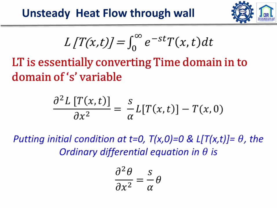
Unsteady Heat Flow through wall

Unsteady Heat Flow through wall
Solving the ODE, solution is obtained in 𝜃& inverse transform gives the solution
Solving the auxiliary equation
𝐷2 =𝑠
𝛼, 𝐷 = ±
𝑠
𝛼= ±𝑝
𝜽 = 𝐴𝑒−𝑝𝑥 + 𝐵𝑒𝑝𝑥 (General solution)𝑑𝜽
𝑑𝑥= −𝑝𝐴𝑒−𝑝𝑥 + 𝑝𝐵𝑒𝑝𝑥
For x=0, 𝜽 = 𝜽𝟎, ∅ = ∅𝟎= −𝒌 (𝒅𝜽
𝒅𝒙) (𝑫𝒆𝒇𝒊𝒏𝒆𝒅)
𝜃0 = 𝐴 + 𝐵∅0 = 𝑘𝑝𝐴 − 𝑘𝑝𝐵

Unsteady Heat Flow through wall
𝜃0 = 𝐴 + 𝐵………..1
∅0 = 𝑘𝑝𝐴 − 𝑘𝑝𝐵……..2
Solving above two equations…
𝐴 =1
2𝜃0 +
∅0
𝑘𝑝
𝐵 =1
2𝜃0 −
∅0
𝑘𝑝

Unsteady Heat Flow through wall
𝜃 & ∅ 𝑐𝑎𝑛 𝑏𝑒 𝑟𝑒𝑤𝑟𝑖𝑡𝑡𝑒𝑛 𝑖𝑛 𝑡𝑒𝑟𝑚𝑠 𝑜𝑓 𝜃0, ∅0
𝜃 =1
2𝜃0 +
∅0
𝑘𝑝𝑒−𝑝𝑥 +
1
2𝜃0 −
∅0
𝑘𝑝𝑒𝑝𝑥
𝜃 =1
2𝜃0 𝑒−𝑝𝑥 + 𝑒𝑝𝑥 +
1
2
∅0
𝑘𝑝𝑒−𝑝𝑥 − 𝑒𝑝𝑥
By replacing
(𝑒−𝑝𝑥 + 𝑒𝑝𝑥)/2 = cosh-𝑝𝑥&
(𝑒−𝑝𝑥−𝑒𝑝𝑥)/2 = -2sinh-𝑝𝑥

Unsteady Heat Flow through wall
𝜃 =1
2𝜃0 𝑒−𝑝𝑥 + 𝑒𝑝𝑥 +
1
2
∅0
𝑘𝑝𝑒−𝑝𝑥 − 𝑒𝑝𝑥
Replacing, p, & using hyperbolic functions𝜃 𝑥, 𝑠
= 𝜃0(0, 𝑠)𝑐𝑜𝑠ℎ𝑠
𝛼𝑥 −
∅0(0, 𝑠)
𝑘𝑝𝑠𝑖𝑛ℎ
𝑠
𝛼𝑥
Unsteady Heat Flow through wall
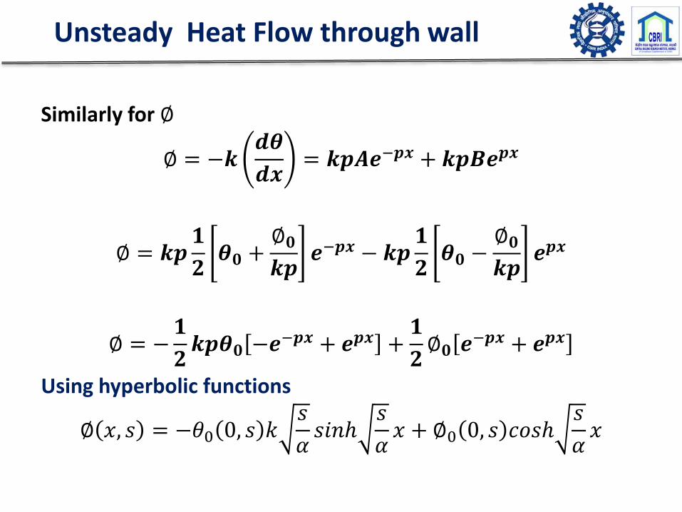
Similarly for ∅
∅ = −𝒌𝒅𝜽
𝒅𝒙= 𝒌𝒑𝑨𝒆−𝒑𝒙 + 𝒌𝒑𝑩𝒆𝒑𝒙
∅ = 𝒌𝒑𝟏
𝟐𝜽𝟎 +
∅𝟎
𝒌𝒑𝒆−𝒑𝒙 − 𝒌𝒑
𝟏
𝟐𝜽𝟎 −
∅𝟎
𝒌𝒑𝒆𝒑𝒙
∅ = −𝟏
𝟐𝒌𝒑𝜽𝟎 −𝒆−𝒑𝒙 + 𝒆𝒑𝒙 +
𝟏
𝟐∅𝟎 𝒆−𝒑𝒙 + 𝒆𝒑𝒙
Using hyperbolic functions
∅ 𝑥, 𝑠 = −𝜃0 0, 𝑠 𝑘𝑠
𝛼𝑠𝑖𝑛ℎ
𝑠
𝛼𝑥 + ∅0 0, 𝑠 𝑐𝑜𝑠ℎ
𝑠
𝛼𝑥
Unsteady Heat Flow through wall
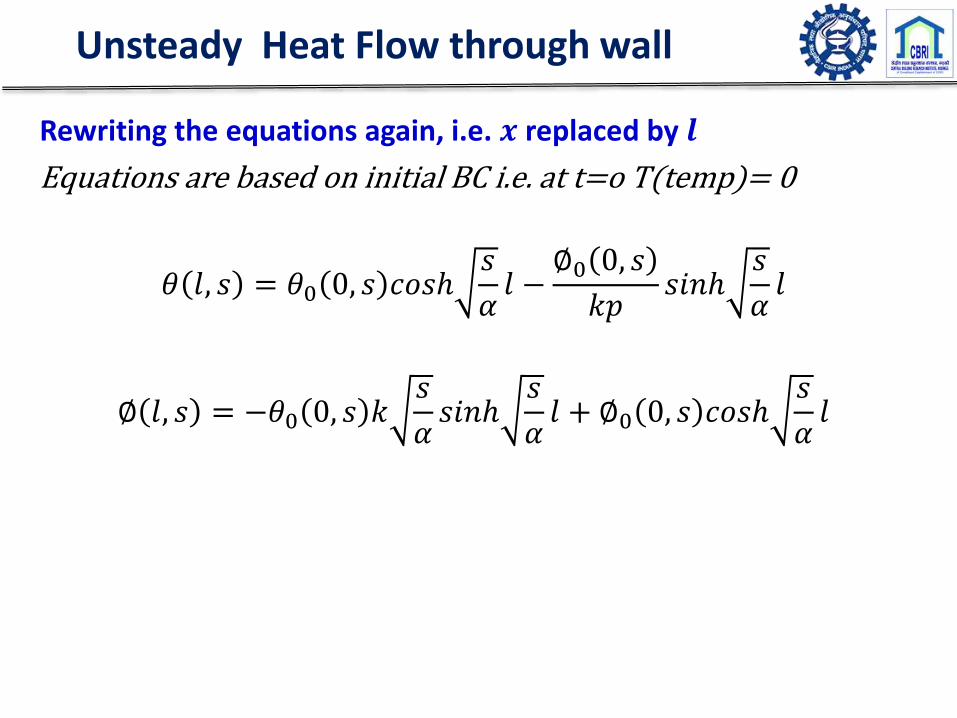
Rewriting the equations again, i.e. 𝒙 replaced by 𝒍
Equations are based on initial BC i.e. at t=o T(temp)= 0
𝜃 𝑙, 𝑠 = 𝜃0 0, 𝑠 𝑐𝑜𝑠ℎ𝑠
𝛼𝑙 −
∅0 0, 𝑠
𝑘𝑝𝑠𝑖𝑛ℎ
𝑠
𝛼𝑙
∅ 𝑙, 𝑠 = −𝜃0 0, 𝑠 𝑘𝑠
𝛼𝑠𝑖𝑛ℎ
𝑠
𝛼𝑙 + ∅0 0, 𝑠 𝑐𝑜𝑠ℎ
𝑠
𝛼𝑙

Unsteady Heat Flow through wall
In matrix form,𝜃(𝑙, 𝑠)∅(𝑙, 𝑠)
=𝑚11 𝑚12
𝑚21 𝑚22
𝜃(0, 𝑠)∅(0, 𝑠)
𝑚11 = 𝑚22 = cosh𝑠
𝛼𝑙 ;
𝑚12 = −1
𝑘𝑠𝛼
sinh𝑠
𝛼𝑙
𝑚21 = −𝑘𝑠
𝛼sinh
𝑠
𝛼𝑙

Unsteady Heat Flow through wall: Layered Construction
𝜽(𝒍𝟏, 𝒔)∅(𝒍𝟏, 𝒔)
=𝒎𝟏𝟏
𝟏 𝒎𝟏𝟐𝟏
𝒎𝟐𝟏𝟏 𝒎𝟐𝟐
𝟏
𝜽(𝟎, 𝒔)∅(𝟎, 𝒔)
𝜽(𝒍𝟐, 𝒔)∅(𝒍𝟐, 𝒔)
=𝒎𝟏𝟏
𝟐 𝒎𝟏𝟐𝟐
𝒎𝟐𝟏𝟐 𝒎𝟐𝟐
𝟐
𝜽(𝒍𝟏, 𝒔)∅(𝒍𝟏, 𝒔)

Unsteady Heat Flow through wall
𝜃(𝑙2, 𝑠)∅(𝑙2, 𝑠)
=𝑚11
2 𝑚122
𝑚212 𝑚22
2
𝑚111 𝑚12
1
𝑚211 𝑚22
1
𝜃(0, 𝑠)∅(0, 𝑠)
𝜃(𝐿, 𝑠)∅(𝐿, 𝑠)
=𝐴 𝐵𝐶 𝐷
𝜃(0, 𝑠)∅(0, 𝑠)
𝐴 𝐵𝐶 𝐷
=𝑚11
2 𝑚122
𝑚212 𝑚22
2
𝑚111 𝑚12
1
𝑚211 𝑚22
1 …...

Unsteady Heat Transfer
For air layer ,
Thermal capacity of air layer is very small
Therefore, assume 𝝆𝑪 → 𝟎, &𝒌
𝝆𝑪= 𝜶 → ∞,
That mean it will allow heat to go instantaneously,
𝒍𝒔
𝜶→ 𝟎
𝒎𝟏𝟏 = 𝒎𝟐𝟐 = 𝒄𝒐𝒔𝒉𝒔
𝜶𝒍 → 𝟏
𝒍𝒊𝒎𝒔
𝜶l→ 𝟎

Unsteady Heat Transfer
𝒎𝟏𝟐 = −𝟏
𝒌𝒔
𝜶
𝒔𝒊𝒏𝒉𝒔
𝜶𝒍 =
𝒍
𝒌−
𝒔𝒊𝒏𝒉𝒔
𝜶𝒍
𝒔
𝜶𝒍
= −𝒍
𝒌= -1/h
𝑳𝒊𝒎𝒔
𝜶𝒍 → 𝟎 𝒍𝒊𝒎
𝒔
𝜶𝒍 → 𝟎
For Air Layer
𝑚11 𝑚12
𝑚21 𝑚22= 1 −
1
ℎ0 1

Unsteady Heat Flow through wall
To simplify again,
When, s=i𝛚 is used in Laplace transform & using lower limit of integration as -∞ ; for 𝟏𝒔𝒕 harmonic.
• All temperature and heat fluxes are multiplied by 𝒆−𝒊𝝎𝟏𝒕& integrated from -∞ to +∞ to obtain the transform
𝟎
∞
𝒆−𝒊𝝎𝟏𝒕𝑻 𝒕 𝒅𝒕 = −∞
∞
𝑻 𝒕 𝒄𝒐𝒔(𝝎𝟏𝒕) 𝒅𝒕 − 𝒊 −∞
∞
𝑻 𝒕 𝒔𝒊𝒏(𝝎𝟏𝒕)𝒅𝒕
=𝝅(𝒂𝟏 − 𝒊𝒃𝟏)
a1 and b1 is Fourier's coefficient

Unsteady Heat Transfer
𝜋 𝑎1 − 𝑖𝑏1 = 𝜋𝑇𝑜𝑒−𝑖𝜔1𝑡
𝑇𝑜 = (𝑎12+ 𝑏1
2)
𝜔1 = tan−1(−𝑏1/𝑎1)
T(t), q(t) thus gets transformed to Fourieramplitude for the corresponding harmonicmultiplied by 𝜋𝑒−𝑖𝜔1𝑡

Transmission Matrix
All temperature & heat fluxes are multiplied byexponent π𝑒−𝑖𝜔,𝑡 ; π𝑒−𝑖𝜔,𝑡 can be ignored butrespective 𝜔, need to be used in the transmissionmatrix.
𝑇𝐿
𝑞𝐿=
𝑚11 𝑚12
𝑚21 𝑚22
𝑇𝑜
𝑞𝑜
𝑚11= 𝑚22 = cosh 𝑖𝜔
𝛼l;
𝑚12= -1
𝑘𝑖𝜔
𝛼
sinh 𝑖𝜔
𝛼l
𝑚21= - 𝑘𝑖𝜔
𝛼sinh
𝑖𝜔
𝛼l

Transmission Matrix
𝑖1/2(w/α)1/2
= (2𝑖)1/2(w/2α)1/2
(2𝑖)1/2= [(1+i)2]1/2=1+i
F = (w/2α)1/2
𝑚11= cosh (Fl + iFl)
𝑚12= - sinh (Fl + iFl) / (kF + ikF)
𝑚21= (-kF + ikF) sinh (Fl + iFl)
𝑚22= cosh (Fl + iFl)

Transmission Matrix
𝑇 (𝑙)𝑞 (𝑙)
=𝐴 𝐵𝐶 𝐷
𝑇 (0)𝑞 (0)
OR𝑇𝑖
𝑞𝑖=
𝐴 𝐵𝐶 𝐷
𝑇𝑜
𝑞𝑜

Frequency Domain Response factors
Admittance factor (Ỹ ):
This is defined as the amount of energy entering asurface for each degree of temperature swing at theenvironmental point.
It is used to represent enclosure response to give the equivalentswing in temperature about some mean value due to a cyclic loadon an enclosure.
Consequently mathematically defined as,
Ỹ(l,t)=𝒒 (𝒍,𝒕)
𝑻(𝟎,𝒕)=
𝒒𝒊
𝑻𝒊= heat flux/swing of inside temperature
qi will be find by decrement factor and utilised here to find the internal room temperature

Ỹ can be determined from transmission matrix, assuming constant outside temperature, i.e. Ťo=0
Admittance response factor
𝑻𝒊𝒒𝒊
=𝑨 𝑩𝑪 𝑫
𝑻𝒐𝒒𝒐
For Ťo =0 Ti = Bqo
qi= Dqo
Ỹ=𝒒𝒊
𝑻𝒊=
𝑫
𝑩

To simplify again,
Decrement response factor (µ ):
This is defined as the ratio of the cyclic flux transmission to thesteady state flux transmission. (Or temperature)
It is applied to fluctuations (about mean) in externaltemperature or flux harmonics impinging on exposed opaquesurfaces undergoing transient heat transfer.
Consequently mathematically defined as,
Ũ=𝒒 (𝒍,𝒕)
𝑻(𝟎,𝒕)=
𝒒𝒊
𝑻𝒐= heat flux/swing of outside temperature
µ=Ũ
𝑼
Frequency Domain response Factor

Decrement response factor
µ can be determined from Transmission matrix assuming constant inside temperature i.e. Ťi = 0
𝑻𝒊𝒒𝒊
=𝑨 𝑩𝑪 𝑫
𝑻𝒐𝒒𝒐
𝑻𝒐𝒒𝒐
=𝑨 𝑩𝑪 𝑫
− 𝟏𝑻𝒊𝒒𝒊
𝑻𝒐𝒒𝒐
=𝑫 −𝑩−𝑪 𝑨
𝑻𝒊𝒒𝒊
For Ťi =0 To = -Bqi
Ũ=𝒒𝒊
𝑻𝒐=
𝟏
−𝑩µ =
𝟏
𝑼 (−𝑩)

Decrement Factor
M’ = inv(M)
1/-B = 1/M’ (1,2);
U= (1/(1/ho+l/k+1/hi))
(Complex decrement) Cdec = 1/-BU
µ = abs(cdec)
𝟇 = angle (cdec/U)𝝿*12
1/-BU =X+iY
µ = 𝑿𝟐 + 𝒀𝟐
Tan(𝟇) = Y/X

Ventilation Heat Exchange (Qcv)
Outside air coming In= Inside air going out
If air flow = V m3/sec
i.e. volume exchange in unit time (sec) = V m3
Cp – Specific heat of air at constant pressure
Ρ= Density of air
Qcv= ρVCp (Toa- Tia)
ρCp – Volumetric heat capacity = 1300 Joules/K. m3
VR= Volume of room
N = Number of air change per hr.
Qcv= 1300/3600 N VR (Toa-Tia)= 1/3 N VR (Toa-Tia)

Radiation Heat Exchange (QR)
QR= 𝑰 𝑨𝑾θ
Where,
I= Intensity of radiation (W/m2 )
θ – Solar Gain factor= 1 for open windows
AW- Area of Window
Casual Heat Gain (Qcs)
Qcs = 𝒎𝒊𝑸𝒊

If inside & out side mean temperature constant.
QR and Qcs- Heat gain
Qcd & Qcv- Heat loss
Mean Temperature in the space
𝑸𝒄𝒅 = 𝑼𝒋𝑨𝒋(𝑻𝒐𝒆 − 𝑻𝒊𝒂) = 𝑼𝒋𝑨𝒋(𝑻𝒐𝒂 + (α l / 𝒉𝒐)𝒋−𝑻𝒊𝒂)
Toe- Equivalent sol air temperature
𝑸𝒄𝒅 = 𝑼𝒋𝑨𝒋 𝑻𝒐𝒂 − 𝑻𝒊𝒂 + 𝑼𝒋𝑨𝒋(α l / 𝒉𝒐)𝒋
For steady state mean temperature 𝑸𝒄𝒅 + 𝑸𝑹 + 𝑸𝒄𝒗 + 𝑸𝒄𝒔 = 𝟎

Mean Temperature in the space
𝑼𝒋𝑨𝒋( 𝑻𝒐𝒂 − 𝑻𝒊𝒂) + 𝑼𝒋𝑨𝒋(α ī / 𝒉𝒐)𝒋+ 𝑨ī 𝜽 + 𝑪𝑽
𝑻𝒐𝒂 − 𝑻𝒊𝒂 + 𝑸𝒄𝒔 = 𝟎
𝑼𝒋𝑨𝒋( 𝑻𝒐𝒂 − 𝑻𝒊𝒂) + 𝑪𝑽 𝑻𝒐𝒂 − 𝑻𝒊𝒂 + 𝑸 = 𝟎
𝑻𝒐𝒂 − 𝑻𝒊𝒂 = − 𝑸/( 𝑼𝒋𝑨𝒋 + 𝑪𝑽)
𝑻𝒊𝒂 = 𝑻𝒐𝒂 + { 𝑸/( 𝑼𝒋𝑨𝒋 + 𝑪𝑽)}
Where,
𝑸 = 𝑼𝒋𝑨𝒋(α ī / 𝒉𝒐)𝒋+ 𝑨ī 𝜽 + 𝑸𝒄𝒔

A room 6 m x 5 m x 3m (ht) with one external wall on thelong axis has a single glazed window 4.5 m x 2 m facingsouth. Calculate the mean internal temperature giventhat Toa = 17° C and the mean global irradiance onexposed wall is 180 W/m2 . Assume α of solid wall = 0.4and ho 9 W/m2.
Uwall = 0.7. U-window= 5.6.
Assume two air changes per hour for the room and alladjacent room to be the same temperature. Solar gainfactor for glass = 0.76.
Mean Temperature in the space

Mean Temperature in the space
VR= 6 x 5x3 = 90m2
A window= 4.5 x 2= 9 m2
A wall = 6x 3 -9 = 9 m2
I = 180 W/m2
Mean heat gain through wall = UA (α I/ho)
=0.7x 9 x 0.4 x180/9=50.4 W
Mean heat gain through window= AIθ
= 9 x 180x 0.76 = 1231.2 W

Mean Temperature in the space
𝐂𝐯 =𝟏
𝟑𝐍𝐕𝐑 =
𝟏
𝟑∗ 𝟐 ∗ 𝟗𝟎 = 𝟔𝟎 𝐖/°𝐂
UjAj = 0.7*9+ 5.6*9 = 56.7
𝑻𝒊𝒂 = 𝑻𝒐𝒂 + { 𝑸/( 𝑼𝒋𝑨𝒋 + 𝑪𝑽)}
Tia = 17 + {1281.6/(60+56.7) }
= 17+ {1281/116.7 }
= 27.9°C

Inside Temperature
𝑹𝒆𝒄𝒂𝒍𝒍, 𝑴𝒆𝒂𝒏 𝑹𝒐𝒐𝒎 𝒕𝒆𝒎𝒑𝒆𝒓𝒂𝒕𝒖𝒓𝒆
Ť𝒊 = Ť𝒐 +Ǭ𝑻
( 𝑨𝑼 + 𝑪𝒗)
Ǭ𝑻 = 𝑸𝑹 + 𝑸𝒄𝒔
𝑹𝒐𝒐𝒎 𝒕𝒆𝒎𝒑𝒆𝒓𝒂𝒕𝒖𝒓𝒆 𝒂𝒕 𝒂𝒏𝒚 𝒊𝒏𝒔𝒕𝒂𝒏𝒕 𝒕 𝒊𝒔:
Ti(t) = Ť𝒊 + Ť𝒊 (t) (Fluctuating component)
Ť𝒊 (t) swing needs to be obtained

Fluctuating Heat gains
The total fluctuating energy gain at the environmental point and due to any particular excitation frequency is given by:
𝑸𝑻 𝒕 = 𝑸𝒇𝒔 𝒕 + 𝑸𝑺 𝒕 + 𝑸𝒄 𝒕 + 𝑸𝒇𝒄 𝒕 + 𝑸𝒗 𝒕
Where,
𝑸𝒇𝒔 𝒕 - Solar radiation on Opaque body fluctuating heat gain
𝑸𝑺 𝒕 - Transparent surface solar fluctuating heat gain
𝑸𝒄 𝒕 - Casual gain fluctuating heat
𝑸𝒇𝒄 𝒕 - Opaque surface fluctuating heat gain
𝑸𝒈𝒄 𝒕 - Transparent surface conduction fluctuating heat gain
𝑸𝒗 𝒕 - Fluctuating ventilation heat transfer

Fluctuating Heat gains
Solar radiation on Opaque body fluctuating heat gain 𝑸𝒇𝒔 𝒕 =
𝑄𝑓𝑠 𝑡 =
𝑖=1
𝑁
[ 𝐴𝑖𝑈𝑖𝑅𝑜𝜇𝑖𝛼𝑖 𝐼𝑠𝑜 𝑡 − ∅𝑑 ]
Opaque surface fluctuating heat gain 𝑸𝒇𝒄 𝒕 =
𝑄𝑓𝑐 𝑡 =
𝑖=1
𝑂
[ 𝐴𝑖𝑈𝑖𝜇𝑖 𝑇𝑜 𝑡 − ∅𝑑 ]
Where,
𝝁 -Ũ
𝑼=Decrement response factor
Ro= 1/ho= surface heat transfer resistance coefficient
∅𝒅 is decrement time lag 𝑰𝒔𝒐 𝒕 − ∅𝒅 = 𝑰𝒔𝒐 𝒕 − ∅𝒅 − 𝑰𝒔𝒐

Fluctuating Heat gains and Internal temperature
Fluctuating heat gain through surfaces and gain of air is equal to fluctuating heat input over mean
𝑻𝒊 𝒕 𝑨𝒀 + 𝑪𝒗 = 𝑸𝑻(𝒕 − ∅𝒂)
𝑻𝒊 𝒕 = 𝑸𝑻 𝒕 − ∅𝒂
𝑨𝒀 + 𝑪𝒗
Where, Y is admittance factor∅𝒂= time lag

Thermal Admittance
• Thermal performance of the wall/roofs can bemeasured by two parameters: thermal insulation andthermal mass.
• Thermal transmittance is a steady-state property and itis the measure of thermal insulation
• Thermal admittance (w/mk) is the measure of thermal
mass. An ability to absorb the heat from andrelease it to a space over time.
• Amount of energy leaving the internal surface of theelement into the room per unit degree of temperatureswing

• This can be used for thermal storage capacity of amaterials absorbing heat from and releasing it to aspace through cyclic temperature variations and thusevening out temperature variations and so reducingthe building services system.
• This is a measure of the ability of a surface to smoothout temperature variations in a space and representsthe rate of energy entry into a structure rather thanthat of passage through it.
Thermal Admittance
For reduced cooling loads, thermal transmittance should be as low as possible and thermal admittance should be
as high as possible.

Thermal transmittance
• Thermal transmission through unit area of a building unit divided by
the temperature difference between the air or other fluid on either
side of the building unit in steady state conditions is termed as
Thermal Transmittance (U-value).
Overall U- factor of typical wall assembly construction:
U = 1/ (1/hi + ∑n Li/ Ki + 1/ ho)…….. (i)i=1
Where, ho (19.90 W/(m2 K) and hi (9.3 W/(m2 K) are the outside and inside film heat transfer coefficients, Li and Ki
are thicknesses and thermal conductivities of material layers.
•A measure of the overall ability of a building element (wall / window /
floor / roof) to prevent heat loss (W/m2K).
It includes: Material resistances, surface resistances & air space
resistances

The provisions of this code apply to:
(a) Building envelope
(b) Thermal comfort systems andcontrols (only those installed bydeveloper/ owner)
(c) Lighting systems and controls (onlythose installed by developer/ owner)
(d) Electrical systems (installed bydeveloper/ owner)
(e) Renewable energy systems
Energy Conservation Building Code

Energy Conservation Building Code (Code) is to provide minimum requirements for the energy-efficient design and
construction of buildings
ECBC 2017 Requirements
Table 4.7 Opaque Assembly Maximum U-factor (W/m2) Requirements for a ECBC compliant building
Table 4.8 Opaque Assembly Maximum U-factor (W/m2) Requirements for a ECBC + compliant building
Table 4.7 Opaque Assembly Maximum U-factor (W/m2) Requirements for Super ECBC building
Composite Hot and dry Warm and humid Temperate Cold
All building types, except below 0.34 0.34 0.34 0.55 0.22
No Star Hotel < 10,000AGA 0.44 0.44 0.44 0.44 0.34
Business <10,000AGA 0.44 0.44 0.44 0.55 0.34
School <10,000AGA 0.63 0.63 0.63 0.75 0.44
Composite Hot and dry Warm and humid Temperate Cold
All building types, except below 0.40 0.40 0.40 0.55 0.34
No Star Hotel < 10,000AGA 0.63 0.63 0.63 0.63 0.40
Business <10,000AGA 0.63 0.63 0.63 0.63 0.40
School <10,000AGA 0.85 0.85 0.85 1.00 0.40
Composite Hot and dry Warm and humid Temperate Cold
All building types 0.22 0.22 0.22 0.22 0.22

Roof Assembly Max. U- factor Requirements
The Roof Insulation shall be applied externally as part of the Structural Slab and not as part of the False CeilingTable 4.4 Roof Assembly U-factor (W/m2) Requirements for ECBC Compliant building
Composite Hot and dry Warm and humid Temperate Cold
All building types, except below 0.33 0.33 0.33 0.33 0.28
School <10,000AGA 0.47 0.47 0.47 0.47 0.33
Hospitality > 10,000AGA 0.20 0.20 0.20 0.20 0.20
Table 4.5 Roof Assembly U-factor (W/m2) Requirements for ECBC + Compliant building
Composite Hot and dry Warm and humid Temperate Cold
Hospitality, Healthcare
Assembly0.20 0.20 0.20 0.20 0.20
Business Educational Shopping
Complex0.26 0.26 0.26 0.26 0.20
Table 4.6 Roof Assembly U-factor (W/m2) Requirements Super ECBC building
Composite Hot and dry Warm and humid Temperate Cold
All Building types 0.20 0.20 0.20 0.20 0.20

Thermal Transmittance for Different Roofing Systems
Building Sections / Components U-value
(W/m2K)
R.C. Plank and joist roofing system 60 mm RC plank + 50 mm
mud phuska + 50 mm brick tiles + 15 mm cement plaster
2.71
100 mm thick R.B.C slab + 50 mm mud phuska + 50mm brick
tiles + 15 mm cement plaster
2.36
Brick panel roofing system: Panel size 1150 x 530 x 76 mm +
R.C.C Joist
2.16
115 mm RCC + 75mm Mud Phuska + 50 mm brick tile 2.01
None of the Roofing Assemblies fulfill the ECBC Criteria

Energy Conservation Building Code

Energy Conservation Building Code – Residential 2018
• RETV is the net heat gain rate (over the cooling period) through the buildingenvelope of dwelling units (excluding roof) divided by the area of thebuilding envelope (excluding roof) of dwelling units. Its unit is W/m2
• Thermal transmittance of the building envelope (except roof) for coldclimate shall comply with the maximum of 1.8 W/m2.K.
• Thermal transmittance of roof shall comply with the maximum URoofvalue of 1.2 W/m2K
Residential Envelope TransmittanceValue (RETV) for building envelope(except roof) shall comply with themaximum RETV of 15 W/m2
• Code sets minimum performance standards for building envelope tolimit heat gains (for cooling dominated climates) and limit heat loss(for heating dominated climates) through it.
n
ii
n
ii
n
ii
envelope
SHGCA
UA
UA
A
eqopaquenonc
opaquenonopaquenonb
opaqueopaquea
RETV
ii
ii
ii
1
1
1
1
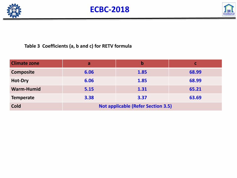
ECBC-2018
Table 3 Coefficients (a, b and c) for RETV formula
Climate zone a b c
Composite 6.06 1.85 68.99
Hot-Dry 6.06 1.85 68.99
Warm-Humid 5.15 1.31 65.21
Temperate 3.38 3.37 63.69
Cold Not applicable (Refer Section 3.5)

Thermal Admittance & Transmittance
5.8
5.85
5.9
5.95
6
6.05
6.1
6.15
6.2
6.25
6.3
0 20 40 60 80 100 120 140 160
Ad
mit
tan
ce (
w/K
m
Insulation Thickness (mm)
EPS (K = 0.035)
PUF (K = 0.027)
Foam concrete (K = 0.070)
Roof
0
0.5
1
1.5
2
2.5
3
0 50 100 150
Tra
nsm
itta
nce
(w
/Km
2
Insulation Thickness (mm)
EPS (K = 0.035)
PUF (K = 0.027)
Foam concrete (K =
0.070)
4.8
4.9
5
5.1
5.2
5.3
5.4
5.5
5.6
0 50 100 150 200
Ad
mit
tan
ce (
w/m
k)
Insulation Thickness (mm)
Foam concrete (K = 0.070)
Fiber glass (K = 0.040)
EPS (K = 0.035)
PUF (K = 0.027)
Wall
0
0.5
1
1.5
2
2.5
3
3.5
0 50 100 150 200
Tra
nsm
itta
nce
(w
/m2
k)
Insulation Thickness (mm)
Foam concrete (K = 0.070)
Fiber glass (K = 0.040)
EPS (K = 0.035)
PUF (K = 0.027)

CLIMATOLOGY : Thermal Comfort
• Thermal Comfort: Necessary to create an indoor comfortable environment
• The total heat produced by the body should balance the heat loss from it,
irrespective of the surrounding environmental conditions
• Indices of Thermal Comfort : Estimation of thermal stress due to a wide range of
climatic conditions Effective temperature (ET) & Tropical summer Index (TSI)
Effective Temperature:
• Definition : Temperature of still saturated air which has the same general effect
upon comfort as the atmosphere under investigation.
• Combinations of Temperature + Wind + Humidity same thermal sensation ≡
same ET
Tropical Summer Index (Developed by CBRI)
• Definition : The TSI is defined as the temperature of calm air, at 50 percent
relative humidity which imparts the same thermal sensation as the given
environment.
• TSI = .308 tw + .745tg - 2.06 √(V+. 841) .5 tw + .75tg - 2 √V
• The thermal comfort of subjects was found to lie between TSI values of 25 and
30°C with optimum conditions at 27.5°C
• 30-34°C : tolerable heat 19-25°C : tolerable cool

CLIMATOLOGY : Thermal Comfort
• These climatic conditions are shown on psychometric chart for all the three
seasons, superposed on the same chart are lines of equal TSI for various levels
of thermal comfort.
• It is possible to minimize the rigours of thermal discomfort by a judicious
choice of
Orientation
Layout plan
Building materials
in the construction of buildings to suit the outdoor climate

Thank You
Acknowledgements:
• Prof. Biwajeet Battacharji, IIT Delhi
• CSIR-CSIO, Chennai