Status of M50 Modular Coils Winding form models based on m50_256.z01 have been posted in...
7
Status of M50 Modular Coils • Winding form models based on m50_256.z01 have been posted in Pro/INTRALINK • Working on tee/clamps, wings, port openings, poloidal break, flanges • Propose slight modifications to WC using spline optimization, manual tweaks M1, Type A, se141-011 M2, Type B, se141-012 M3, Type C, se141-013
-
Upload
jamal-alligood -
Category
Documents
-
view
214 -
download
0
Transcript of Status of M50 Modular Coils Winding form models based on m50_256.z01 have been posted in...

Status of M50 Modular Coils
• Winding form models based on m50_256.z01 have been posted in Pro/INTRALINK• Working on tee/clamps, wings, port openings, poloidal break, flanges• Propose slight modifications to WC using spline optimization, manual tweaks
M1, Type A, se141-011
M2, Type B,se141-012
M3, Type C,se141-013
CDR m50_256.z01
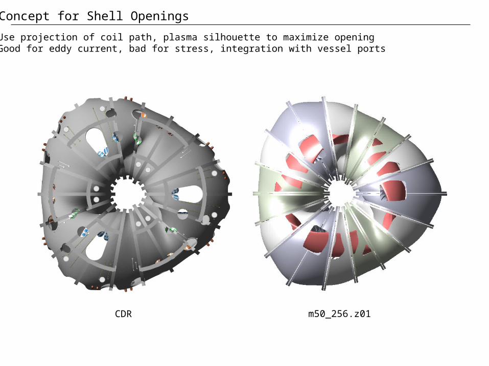
Concept for Shell Openings
• Use projection of coil path, plasma silhouette to maximize opening• Good for eddy current, bad for stress, integration with vessel ports

M1 (v=0)
M2
M3
<7-in to M1
Coil set #m50_256.z01Dots indicate dist from coil to coil-on-left is < 7-in
Proposed Winding Center Modification• Desire to increase spacing, minimize small “wiggles” through inboard trough region
4.35-in(was 4.0)
4.65-in(was 5.0)

m50.e01(blue)
coils.m50_256.z01(red)
Manual tweak case, e01• Case m50.e01 created by moving points on WS, global smoothing of control points• Max deviation from original is 1.9-cm, coil-coil min distance is 6.0-in (was 6.09-in)
M1(m50.e01)

m50_256.z01(red) m50.e02
(blue)
Manual tweak case, e02
• Case m50.e02 created by fixing M3, pushing M2, M1 on WS• Min coil-coil distance increased to 6.46-in between M2 and M3
m50.e01(red)
m50.e03(blue)
M1M2
M3
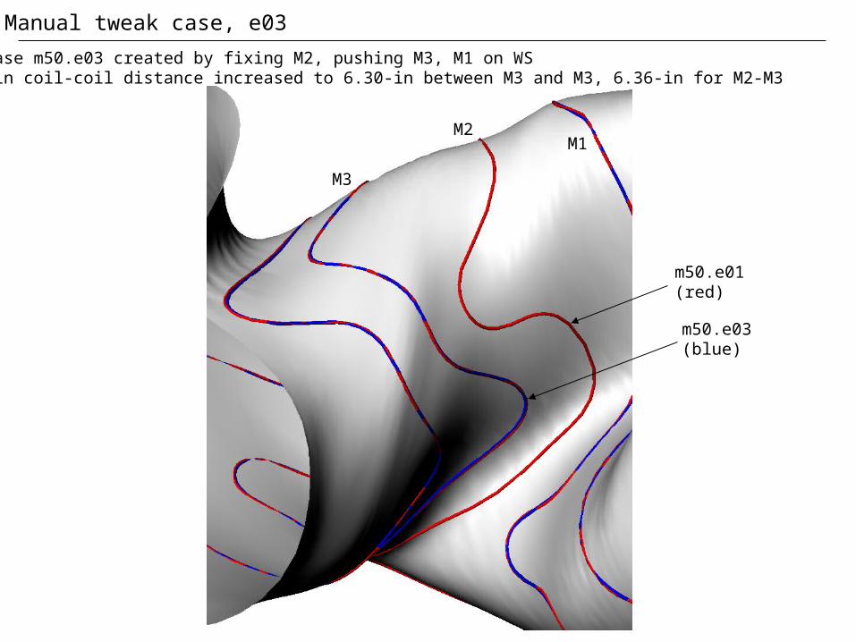
Manual tweak case, e03
• Case m50.e03 created by fixing M2, pushing M3, M1 on WS• Min coil-coil distance increased to 6.30-in between M3 and M3, 6.36-in for M2-M3

Spline optimization cases (D. Strickler)
• Using COILOPT to vary spline representation of coils over a region
M1
M2
M3
Case 022003c
m50_256.z01