Static Analysis of Thin Plates: Bare and...
15
INCAS BULLETIN, Volume 12, Issue 1/ 2020, pp. 67 – 81 (P) ISSN 2066-8201, (E) ISSN 2247-4528 Static Analysis of Thin Plates: Bare and Stiffened Bhargav Reddy ISANAKA* ,1,2 , Abdul Akbar M 2,3 , Vinod KUSHVAHA* ,1 , Biraja Prasad MISHRA 2 *Corresponding authors 1 Department of Civil Engineering, Indian Institute of Technology Jammu, Jagti, PO Nagrota, Jammu – 181 221, J&K, India, [email protected]*, [email protected]* 2 Department of Civil Engineering, Madanaplle Institute of Technology & Science, Angallu, Madanapalle – 517 325, Chittoor, Andhra Pradesh, India, [email protected], [email protected] 3 Department of Civil Engineering, Dr B R Ambedkar National Institute of Technology, G.T. Road, Amritsar Bypass, Jalandhar- 144011, Punjab, India DOI: 10.13111/2066-8201.2020.12.1.7 Received: 13 August 2019/ Accepted: 16 January 2020/ Published: March 2020 Copyright © 2020. Published by INCAS. This is an “open access” article under the CC BY-NC-ND license (http://creativecommons.org/licenses/by-nc-nd/4.0/) Abstract: Plates are being widely used for many structural applications such as aerospace, civil, electronic devices and marine industries etc. For these applications, it is important to know the plate behaviour under static loading condition. The present study focuses on filling the existing gap in the literature in order to know the plate behaviour of different geometrical shapes before and after adding the stiffener. A total of eight geometries namely circular, square, rectangular (with aspect ratio of 1.25, 1.50 and 1.75) and skew square (with 70 o , 76.67 o and 83.33 o skew angles) were considered. Static analysis of considered geometries was carried out by using FEAST (a Finite Element software). To enable comparison of plates, three parameters namely the area of plates, starting point of the stiffener and curvature of the stiffener were kept constant. From the static analysis results, the effect of the curvilinear stiffener on different geometrical shapes, effect of aspect ratio on rectangular plates and effect of skew angle on skew square plates were given. The displacement of plates reduced significantly after adding the curvilinear stiffener to the bare plates and the stiffener was most effective in the case of circular plate. In the present study, the effect of aspect ratio and skew angle on static behaviour of bare and stiffened plates was also studied and discussed. Key Words: Static, plates, geometry, aspect ratio, skew 1. INTRODUCTION Thin plates are commonly used as structural elements in the aerospace, marine, civil and electronic device industries. Mechanical, electrical, thermal and tribological properties can be enhanced by using thin plates [1]. Thin plates in micron- and nano-sizes are employed in Microelectromechanical Systems (MEMS) and Nanoelectromechanical Systems (NEMS). Due to the widespread applications of thin plates, there have been numerous studies on the static, dynamic and buckling behaviour of the plates to explicate their structural performance. The behaviour of plates (bare and stiffened) under static loading condition have been studied
Transcript of Static Analysis of Thin Plates: Bare and...

INCAS BULLETIN, Volume 12, Issue 1/ 2020, pp. 67 – 81 (P) ISSN 2066-8201, (E) ISSN 2247-4528
Static Analysis of Thin Plates: Bare and Stiffened
Bhargav Reddy ISANAKA*,1,2, Abdul Akbar M2,3, Vinod KUSHVAHA*,1, Biraja Prasad MISHRA2
*Corresponding authors 1Department of Civil Engineering, Indian Institute of Technology Jammu,
Jagti, PO Nagrota, Jammu – 181 221, J&K, India, [email protected]*, [email protected]*
2Department of Civil Engineering, Madanaplle Institute of Technology & Science, Angallu, Madanapalle – 517 325, Chittoor, Andhra Pradesh, India,
[email protected], [email protected] 3Department of Civil Engineering,
Dr B R Ambedkar National Institute of Technology, G.T. Road, Amritsar Bypass, Jalandhar- 144011, Punjab, India
DOI: 10.13111/2066-8201.2020.12.1.7
Received: 13 August 2019/ Accepted: 16 January 2020/ Published: March 2020 Copyright © 2020. Published by INCAS. This is an “open access” article under the CC BY-NC-ND license (http://creativecommons.org/licenses/by-nc-nd/4.0/)
Abstract: Plates are being widely used for many structural applications such as aerospace, civil, electronic devices and marine industries etc. For these applications, it is important to know the plate behaviour under static loading condition. The present study focuses on filling the existing gap in the literature in order to know the plate behaviour of different geometrical shapes before and after adding the stiffener. A total of eight geometries namely circular, square, rectangular (with aspect ratio of 1.25, 1.50 and 1.75) and skew square (with 70o, 76.67o and 83.33o skew angles) were considered. Static analysis of considered geometries was carried out by using FEAST (a Finite Element software). To enable comparison of plates, three parameters namely the area of plates, starting point of the stiffener and curvature of the stiffener were kept constant. From the static analysis results, the effect of the curvilinear stiffener on different geometrical shapes, effect of aspect ratio on rectangular plates and effect of skew angle on skew square plates were given. The displacement of plates reduced significantly after adding the curvilinear stiffener to the bare plates and the stiffener was most effective in the case of circular plate. In the present study, the effect of aspect ratio and skew angle on static behaviour of bare and stiffened plates was also studied and discussed.
Key Words: Static, plates, geometry, aspect ratio, skew
1. INTRODUCTION Thin plates are commonly used as structural elements in the aerospace, marine, civil and electronic device industries. Mechanical, electrical, thermal and tribological properties can be enhanced by using thin plates [1]. Thin plates in micron- and nano-sizes are employed in Microelectromechanical Systems (MEMS) and Nanoelectromechanical Systems (NEMS). Due to the widespread applications of thin plates, there have been numerous studies on the static, dynamic and buckling behaviour of the plates to explicate their structural performance. The behaviour of plates (bare and stiffened) under static loading condition have been studied
Bhargav Reddy ISANAKA, Abdul Akbar M, Vinod KUSHVAHA, Biraja Prasad MISHRA 68
INCAS BULLETIN, Volume 12, Issue 1/ 2020
for more than five decades [2-6]. Static analysis for straight and curvilinear stiffened plates by using the Mesh-Free Method (MFM) was studied by Tamijani and Kapania [7]. Their study showed that a curvilinear stiffener performed better compared to a straight stiffener. Liu et al. [8] studied size and surface effects on mechanical behaviour of thin nanoplates by using Isogeometric Analysis (IGA). They concluded that microstructure and surface energy effects increase the nanoplate stiffness, which gives rise to a reduction in bending deflection and an increase in buckling loads. Different numerical and analytical methodologies have been used for studying the behaviour of plates (bare and stiffened) under various loading conditions [9-15]. Recent studies suggest that curvilinear stiffeners provide more stiffness to the overall plate as compared to the straight stiffeners [16 - 22].
The behaviour of plates for different geometrical shapes by comparing the bare versus stiffened case has not been yet studied. To bridge this gap, different geometrical shapes (circular, square, skew and rectangular) were considered in this study. The dimensions are varied (by maintaining constant plate area) for rectangular and skew geometries by means of varying the aspect ratio (length/breadth) and skew angle, respectively. Therefore, in the present study, Finite Element Analysis (FEA) was utilized to study the effect of stiffener for different geometries of the plate under static loading condition.
2. METHODOLOGY Static analysis for the present work was carried out using FEAST (Finite Element Analysis of Structures) software developed by the Indian Space Research Organisation (ISRO) and the Vikram Sarabhai Space Centre (VSSC). The accuracy verification of the finite element model was done by modelling the existing plate geometry with curvilinear stiffeners available in the literature [22] and later the same was compared with the FEAST results. The convergence study plays an important role in the finite element method. Therefore, it must be ensured that an acceptable mesh is used with respect to the shape and size of the elements to achieve the best results. Due to this, in the present work, a convergence study was first carried out for all the considered geometries and after that the geometries are modelled with the converged mesh size. A total of eight geometrical shapes (refer to Figure 5) were considered in the present study. For the individual comparison of considered geometries, the plate area was kept constant and the origin and shape of the stiffener were the same for all the plate geometries. The considered geometries were a circular plate, a square plate, rectangular plates (with aspect ratio 1.25, 1.50, 1.75) and skew square plates (with 70o, 76.67o, 83.33o skew angles).
The plates were analysed to understand their behaviour under static loading with and without the curvilinear stiffener. The position of the stiffener is chosen in such a way that it starts from one corner of the plate (except the circular) and ends at the opposite edge of the plate (refer to Figure 5).
In this study, the out-of-plane displacement and Von-Mises stresses were obtained from the static analysis simulations for an applied uniform pressure. In the present study, four noded isotropic quadrilateral shell element and two noded beam element are used to model the plate and the stiffener, respectively (Figure 1).
2.1 Validation
The present study was validated by comparing results of a geometrical semi-circular, semi-elliptical plate with curvilinear stiffener (as shown in Figure 1) analysed by using Non-Uniform Rational B-Spline Augmented Finite Element Method (NAFEM) which is proposed by Mishra and Barik [22].
69 Static Analysis of Thin Plates: Bare and Stiffened
INCAS BULLETIN, Volume 12, Issue 1/ 2020
Figure 1: Elements used for meshing
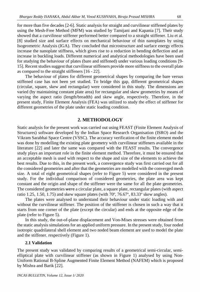
A simply supported semi-circular, semi-elliptical plate having r1 = 12.70 mm and r2= 8.4667 mm, E = 117210 N/mm2, thickness of plate, h = 0.254 mm and Poisson ratio, µ = 0.3 with a curvilinear stiffener passing through the points A (-5.9868 mm, -5.9997 mm), B (-0.99776 mm, 1.1459 mm) and C (8.9803 mm, 5.9828 mm) as shown in Figure 2 was subjected to a uniform pressure of 6.8947 kPa (1.0 Psi) and was analysed using mesh of 32 x 32. The thickness and depth of the stiffener was 0.254mm and 2.54mm, respectively. The used material was identical for both, plate and stiffener.
Figure 2: Semi-circular semi-elliptical plate with curvilinear stiffener passing through the points ABC
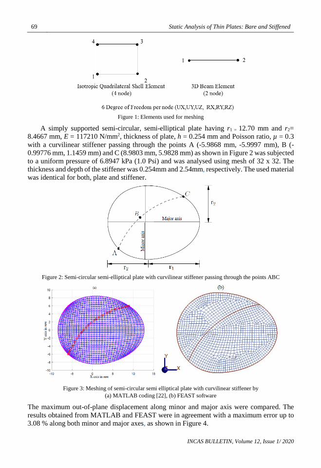
Figure 3: Meshing of semi-circular semi elliptical plate with curvilinear stiffener by (a) MATLAB coding [22], (b) FEAST software
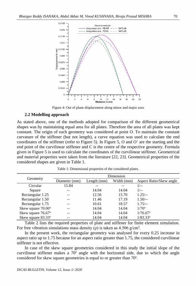
The maximum out-of-plane displacement along minor and major axis were compared. The results obtained from MATLAB and FEAST were in agreement with a maximum error up to 3.08 % along both minor and major axes, as shown in Figure 4.
Bhargav Reddy ISANAKA, Abdul Akbar M, Vinod KUSHVAHA, Biraja Prasad MISHRA 70
INCAS BULLETIN, Volume 12, Issue 1/ 2020
Figure 4: Out of plane displacement along minor and major axes
2.2 Modelling approach
As stated above, one of the methods adopted for comparison of the different geometrical shapes was by maintaining equal area for all plates. Therefore the area of all plates was kept constant. The origin of each geometry was considered at point O. To maintain the constant curvature of the stiffener (but not length), a curve equation was used to calculate the end coordinates of the stiffener (refer to Figure 5). In Figure 5, O and O’ are the starting and the end point of the curvilinear stiffener and C is the centre of the respective geometry. Formula given in Figure 5 is used to calculate the coordinates of the curvilinear stiffener. Geometrical and material properties were taken from the literature [22, 23]. Geometrical properties of the considered shapes are given in Table 1.
Table 1: Dimensional properties of the considered plates.
Geometry Dimension Diameter (mm) Length (mm) Width (mm) Aspect Ratio/Skew angle
Circular 15.84 -- -- 1/-- Square -- 14.04 14.04 1/--
Rectangular 1.25 -- 12.56 15.70 1.25/-- Rectangular 1.50 -- 11.46 17.19 1.50/-- Rectangular 1.75 -- 10.61 18.57 1.75/--
Skew square 70.00o -- 14.04 14.04 1/70o Skew square 76.67o -- 14.04 14.04 1/76.67o Skew square 83.33o -- 14.04 14.04 1/83.33o
Table 2 lists the required properties of plate and stiffener for finite element simulation. For free vibration simulations mass density (ρ) is taken as 4.506 g/cm3.
In the present work, the rectangular geometry was analysed for every 0.25 increase in aspect ratio up to 1.75 because for an aspect ratio greater than 1.75, the considered curvilinear stiffener is not effective.
In case of the skew square geometries considered in this study the initial slope of the curvilinear stiffener makes a 70o angle with the horizontal side, due to which the angle considered for skew square geometries is equal to or greater than 70o.

71 Static Analysis of Thin Plates: Bare and Stiffened
INCAS BULLETIN, Volume 12, Issue 1/ 2020
(a) Circular (aspect ratio 1) (b) Square (aspect ratio 1) (c) Skew square (Skew 700)(aspect ratio 1)
(d) Skew square (Skew 76.670)(aspect ratio 1)
(e) Skew square (Skew 83.330)(aspect ratio 1) (f) Rectangular (aspect ratio 1.25) (g) Rectangular (aspect ratio 1.50) (f) Rectangular (aspect ratio 1.75)
Figure 5: Considered geometries for finite element simulation
𝑦𝑦 = �(385.74− (𝑥𝑥 − 12.21)2)− 13.39 Table 2: Geometrical and material properties of a plate and stiffener
Plate
Support condition Simply supported
Area 197.05 mm2
Young's Modulus 1.1721 × 10⁵ N/mm2
Poisson’s Ratio 0.3
Thickness of plate 0.254 mm
Pressure 6.8942 kPa
Stiffener
Dimension 2.54 mm x 0.254 mm
Young's Modulus 1.1721 × 10⁵ N/mm2
3. RESULTS AND DISCUSSIONS Static analysis for bare and stiffened condition was carried out for all considered geometries namely circular, square, rectangular and skew plates. For all geometrical plates, simply supported boundary condition was adopted and a uniform pressure of 6.8942 kPa was applied. The out-of-plane displacements and Von-Mises stresses were studied and compared. In finite element analysis the geometry, mechanical properties, loads and constrains are applied for

Bhargav Reddy ISANAKA, Abdul Akbar M, Vinod KUSHVAHA, Biraja Prasad MISHRA 72
INCAS BULLETIN, Volume 12, Issue 1/ 2020
each element to generate a matrix equation, which are then assembled to generate a global matrix equation (refer to Equation 1) of the structure.
{𝐹𝐹} = [𝐾𝐾]{𝑢𝑢}
where, {𝐹𝐹} is external force matrix, [𝐾𝐾] is global stiffness matrix and {𝑢𝑢} is displacement matrix. Using Equation 1, the deflections are solved. The deflection values are then used to calculate strain, stress and reactions.
It was observed that due to the addition of the stiffener to the plate, there was a significant reduction in the displacement compared to the respective bare plate case. Figure 6 gives the comparison of displacement for different geometries (bare vs. stiffened). The displacement decreased four times for the circular stiffened plate compared to the respective bare plate which was maximum among all the considered geometries. The effectiveness of the stiffener on displacement across the stiffener is shown in Figure 7. Displacement is reduced at stiffener and plate interaction portion. Table 3 gives the percentage reduction in displacement for bare and stiffened plates. In case of bare rectangular plates, the static behaviour was affected by the aspect ratio. From Figures 5(a) and 6, it was observed that the displacement decreased with the increase in aspect ratio for bare plate geometries. The breadth of the plate decreased with increase in aspect ratio.
Figure 6: Comparison of Out-of-plane maximum displacement in bare and stiffened plates
Table 3: Percentage increase in displacement of stiffened plate compared to bare plate due to the stiffener
Plate geometry Percentage change (%)
Circular 399.62 Square 299.91
Rectangular 1.25 256.25 Rectangular 1.50 183.18 Rectangular 1.75 122.94
Skew 70o 241.03 Skew 76.67o 275.84 Skew 83.33o 294.26
0,0000 0,0020 0,0040 0,0060 0,0080 0,0100
CircularSquare
Rectangular 1.25Rectangular 1.50Rectangular 1.75
Skew 70Skew 76.67skew 83.33
Maximum displacement in mm
Geo
met
ry
Stiffened plates Bare plates

73 Static Analysis of Thin Plates: Bare and Stiffened
INCAS BULLETIN, Volume 12, Issue 1/ 2020
Figure 7: Displacement across the stiffener in stiffened circular plate.
The reduction in breadth causes plate edges along the length to move closer to the center C of the plate (refer to Figure 6) which decreases the maximum displacement of the bare rectangular plates. However, in case of stiffened plates, this behavior is different (refer to Figure 8(a)) due to the combined effect of aspect ratio, stiffener position and geometry. In case of the stiffened plates, with increase in aspect ratio the maximum displacement marginally increases with an increase in the aspect ratio.
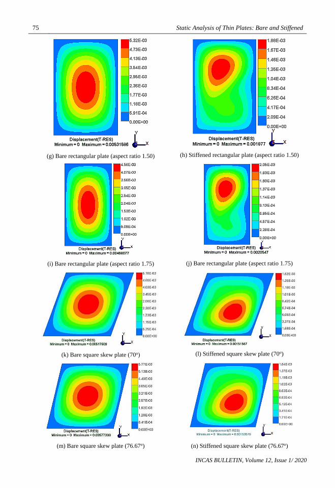
The static behaviour of the plate was also affected with increase in skew angle of the bare and siffened plate. With increase in skew angle, the maximum displacement was increased for bare plates (refer to Figure 6) and marginally increased for stiffened plates. Due to the increase in skew angle, the boundaries of the plate move away from the center C of the plate and subsequently showed the increase in out-of-plane deflection (refer to Figure 8(b)). Among all considered bare plates, the rectangular plate (aspect ratio 1.75) gave the least displacement (0.0046 mm), and among all stiffened plates, skew plate (70o skew angle) produced the minimum displacement (0.0015 mm). Figure 9 shows the displacement contour for all considered geometries of bare and stiffened case.
Figure 8: Effect of (a) aspect ratio (b) skewness on maximum displacement for bare and stiffened plates

Bhargav Reddy ISANAKA, Abdul Akbar M, Vinod KUSHVAHA, Biraja Prasad MISHRA 74
INCAS BULLETIN, Volume 12, Issue 1/ 2020
(a) Bare circular plate
(b) Stiffened circular plate
(c) Bare square plate
(d) Stiffened square plate
(e) Bare rectangular plate (aspect ratio 1.25)
(f) Stiffened rectangular plate (aspect ratio 1.25)
75 Static Analysis of Thin Plates: Bare and Stiffened
INCAS BULLETIN, Volume 12, Issue 1/ 2020
(g) Bare rectangular plate (aspect ratio 1.50)
(h) Stiffened rectangular plate (aspect ratio 1.50)
(i) Bare rectangular plate (aspect ratio 1.75)
(j) Bare rectangular plate (aspect ratio 1.75)
(k) Bare square skew plate (70o)
(l) Stiffened square skew plate (70o)
(m) Bare square skew plate (76.67o)
(n) Stiffened square skew plate (76.67o)

Bhargav Reddy ISANAKA, Abdul Akbar M, Vinod KUSHVAHA, Biraja Prasad MISHRA 76
INCAS BULLETIN, Volume 12, Issue 1/ 2020
(o) Bare square skew plate (83.33o)
(p) Stiffened square skew plate (83.33o)
Figure 9: Out-of-plane displacement contour of bare and stiffened plates (Z – displacements).
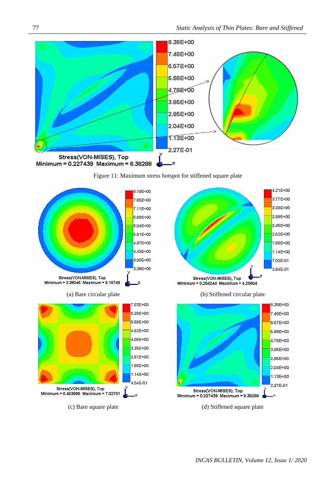
Observations were also made based on the obtained individual maximum plate stresses. From Figure 10, the stress is maximum (8.90 MPa) in the skew plate with 70o angle and minimum (5.86 MPa) for the rectangular plate with aspect ratio 1.75 in the bare case. For the stiffened case, the maximum stress (8.38 MPa) is observed for the square plate, and minimum (4.21 MPa) for the circular plate.
The stresses decreased in skew plates with increase in skew angle for bare case whereas stresses increased with increase in skew angle for the stiffened case.
In the case of rectangular plates, stresses decreased with an increase in aspect ratio for the bare case. But for stiffened rectangular plates there was no clear increasing or decreasing trend.
Due to the curvilinear stiffener, the maximum stress occurred at the bottom left corner of the rectangular and square plates (in the path and the vicinity of the stiffener, refer to Figure 11). The magnitude of maximum and stress at corner is 8.38 MPa.
Therefore, in the case of square and rectangular plates with aspect ratios 1.25 and 1.75 the magnitude of stress was even higher as compared to the respective bare plate cases. Figure 12 shows the stress contour of all considered geometries.
Figure 10: Comparison of maximum Von-Mises stresses in bare and stiffened plates
0 1 2 3 4 5 6 7 8 9
Circular
Square
Rectangular 1.25
Rectangular 1.50
Rectangular 1.75
Skew 70
Skew 76.67
skew 83.33
Stress in MPa
Geo
met
ry
Stiffened plate Bare plate
77 Static Analysis of Thin Plates: Bare and Stiffened
INCAS BULLETIN, Volume 12, Issue 1/ 2020
Figure 11: Maximum stress hotspot for stiffened square plate
(a) Bare circular plate
(b) Stiffened circular plate
(c) Bare square plate
(d) Stiffened square plate

Bhargav Reddy ISANAKA, Abdul Akbar M, Vinod KUSHVAHA, Biraja Prasad MISHRA 78
INCAS BULLETIN, Volume 12, Issue 1/ 2020
(e) Bare rectangular plate (aspect ratio 1.25)
(f) Stiffened rectangular plate (aspect ratio 1.25)
(g) Bare rectangular plate (aspect ratio 1.50)
(h) Stiffened rectangular plate (aspect ratio 1.50)
(i) Bare rectangular plate (aspect ratio 1.75)
(j) Bare rectangular plate (aspect ratio 1.75)

79 Static Analysis of Thin Plates: Bare and Stiffened
INCAS BULLETIN, Volume 12, Issue 1/ 2020
(k) Bare square skew plate (70o)
(l) Stiffened square skew plate (70o)
(m) Bare square skew plate (76.67o)
(n) Stiffened square skew plate (76.67o)
(o) Bare square skew plate (83.33o)
(p) Stiffened square skew plate (83.33o)
Figure 12: Stress contour of bare and stiffened plates.
4. CONCLUSIONS Static analysis of thin plates (bare vs. stiffened) with simply supported boundary conditions, isotropic material properties and curvilinear stiffener with a constant curvature for all considered geometries gave some of the important conclusions based on the plate behaviour. From the present study, the following conclusions were obtained. • Displacement of plates reduced significantly after adding stiffener to the bare plates. • Among all the bare plates, displacement is minimum for the rectangular plate (with aspect
ratio 1.75) and maximum for the circular plate. • In rectangular plates, displacement is reduced with an increase in aspect ratio for the bare
case but increased for the stiffened case.
Bhargav Reddy ISANAKA, Abdul Akbar M, Vinod KUSHVAHA, Biraja Prasad MISHRA 80
INCAS BULLETIN, Volume 12, Issue 1/ 2020
• In bare plates, (in skew ones) displacement increased with the increase in skew angle but only a marginal increase was observed in the stiffened case.
• Among the considered geometries the stiffener was most effective in the case of the circular plate (displacement reduced by four times compared to bare case).
• The stress is maximum (8.90 MPa) in the skew plate with 70o angle and minimum (5.86 MPa) for a rectangular plate with aspect ratio 1.75 in bare case. For the stiffened case, the maximum stress (8.38 MPa) is observed for the square plate and minimum (4.21 MPa) for the circular plate.
• With the increase in skew angle, stresses decreased for the bare case whereas stresses increased with increase in skew angle for the stiffened case.
• The maximum stress occurred at the bottom left corner of the rectangular and square plates (in the path and the vicinity of the stiffener) due to the curvilinear stiffener. Due to this reason, in case of square and rectangular plates with aspect ratios 1.25 and 1.75, the magnitude of stress was even higher as compared to the respective bare plate cases.
ACKNOWLEDGEMENT Authors would like to thank Mr. Aniket Bhelsaikar, CEA support engineer of SVR Info Tech, for his support to understand FEAST and he provided insight and expertise that greatly assisted the research. We would also like to thank ISRO/VSSC for providing the software tool for the present study.
REFERENCES [1] L. Jia, L. Zhang, J. Guo, K. Yao, S. He, Displacement and Stress Analysis of Thin Plate for Cement Concrete
Pavement, https://www.hindawi.com/journals/mpe/2018/3658540/ (accessed Oct 3, 2019). https://doi.org/10.1155/2018/3658540.
[2] S Timoshenko, S. Woinowsky-Krieger, Theory of Plates and Shells, 2nd ed.; McGraw-Hill Inc: New York, 1959.
[3] S. G. Lekhnitskii, Anisotropic Plates, Gordon and Breach, Science Publishers Inc, 1968, Translated by S.W. Tsai and T. Cheron.
[4] M. S. Troitsky, Stiffened Plates: Bending, Stability, and Vibrations, Elsevier Scientific Publishing Company, 1976.
[5] O. Bedair, Analysis and Limit State Design of Stiffened Plates and Shells: A World View, Appl. Mech. Rev., 62 (2), https://doi.org/10.1115/1.3077137, 2009.
[6] M. P. Nemeth, A Treatise on Equivalent-Plate Stiffnesses for Stiffened Laminated-Composite Plates and Plate-like Lattices, NASA/TP-2011-216882, Hampton, Virginia: Langley Research Center, National Aeronautics and Space Administration, 2011.
[7] A. Y. Tamijani, R. K. Kapania, Buckling and Static Analysis of Curvilinearly Stiffened Plates Using Mesh-Free Method,| AIAA Journal, https://arc.aiaa.org/doi/10.2514/1.43917 (accessed Aug 29, 2019).
[8] S. Liu, T. Yu, L. V. Lich, S. Yin, T. Q. Bui, Size and Surface Effects on Mechanical Behavior of Thin Nanoplates Incorporating Microstructures Using Isogeometric Analysis. Comput. Struct., 212, 173–187. https://doi.org/10.1016/j.compstruc.2018.10.009, 2019.
[9] N. K. Jain, N. D. Mittal, Finite Element Analysis for Stress Concentration and Deflection in Isotropic, Orthotropic and Laminated Composite Plates with Central Circular Hole under Transverse Static Loading. Mater. Sci. Eng. A, 498 (1), 115–124. https://doi.org/10.1016/j.msea.2008.04.078, 2008.
[10] T. Nguyen-Thoi, T. Bui-Xuan, P. Phung-Van, H. Nguyen-Xuan, P. Ngo-Thanh, Static, Free Vibration and Buckling Analyses of Stiffened Plates by CS-FEM-DSG3 Using Triangular Elements. Comput. Struct., 125, 100–113. https://doi.org/10.1016/j.compstruc.2013.04.027, 2013.
[11] R. S. Srinivasan, V. Thiruvenkatachari, Static and Dynamic Analysis of Stiffened Plates. Comput. Struct., 21 (3), 395–403. https://doi.org/10.1016/0045-7949(85)90116-6, 1985.
[12] M. Kolli, K. Chandrashekhara, Non-Linear Static and Dynamic Analysis of Stiffened Laminated Plates, Int. J. Non-Linear Mech., 32 (1), 89–101, https://doi.org/10.1016/S0020-7462(96)00016-9, 1997.

81 Static Analysis of Thin Plates: Bare and Stiffened
INCAS BULLETIN, Volume 12, Issue 1/ 2020
[13] M. Guminiak, Static and Free Vibration Analysis of Thin Plates of the Curved Edges by the Boundary Element Method Considering an Alternative Formulation of Boundary Conditions, Engineering Transactions, 64, 3–32, 2016.
[14] X. C. Qin, C. Y. Dong, F. Wang, X. Y. Qu, Static and Dynamic Analyses of Isogeometric Curvilinearly Stiffened Plates, Appl. Math. Model., 45, 336–364, https://doi.org/10.1016/j.apm.2016.12.035, 2017.
[15] G. R. Liu, X. L. Chen, A Mesh-Free Method for Static and Free Vibration Analyses of Thin Plates of Complicated Shape, J. Sound Vib., 241 (5), 839–855, https://doi.org/10.1006/jsvi.2000.3330, 2001.
[16] W. Zhao, K. Singh, R. K. Kapania, Thermal Buckling Analysis and Optimization of Curvilinearly Stiffened Plates with Variable Angle Tow Laminates, J. Spacecr. Rockets, 56 (4), 1189–1204, https://doi.org/10.2514/1.A34378, 2019.
[17] E. Carrera, E. Zappino, T. Cavallo, Static Analysis of Reinforced Thin-Walled Plates and Shells by Means of Finite Element Models, Int. J. Comput. Methods Eng. Sci. Mech., 17 (2), 106–126, https://doi.org/10.1080/15502287.2016.1157647, 2016.
[18] Y. Kumar, The Rayleigh–Ritz Method for Linear Dynamic, Static and Buckling Behavior of Beams, Shells and Plates: A Literature Review, J. Vib. Control, 24 (7), 1205–1227, https://doi.org/10.1177/1077546317694724, 2018.
[19] M. Barik, M. A Mukhopadhyay, New Stiffened Plate Element for the Analysis of Arbitrary Plates. Thin-Walled Struct., 40 (7), 625–639, https://doi.org/10.1016/S0263-8231(02)00016-2, 2002.
[20] H. J. Al-Gahtani, A. E. S. Musa, Analysis of Thin Plates with Internal Rigid Supports of Different Shapes and Layouts by the Boundary Point Method, Arab. J. Sci. Eng., 44 (5), 4213–4223. https://doi.org/10.1007/s13369-018-3347-3, 2019.
[21] S. Zhang, L. Xu, Exact Static Analysis of Eccentrically Stiffened Plates with Partial Composite Action, Compos. Struct., 198, 117–125, https://doi.org/10.1016/j.compstruct.2018.05.049, 2018.
[22] B. R. Isanaka, A. Akbar, B. P. Mishra, V. Kushvaha, Free Vibration Analysis of Thin Plates: Bare Vs. Stiffened, Engineering Research Express, https://doi.org/10.1088/2631-8695/ab6264, 2019
[23] B. P. Mishra, M. Barik, NURBS-Augmented Finite Element Method for Static Analysis of Arbitrary Plates, Comput. Struct., https://doi.org/10.1016/j.compstruc.2017.10.011, 2017.
[24] M. Barik, Finite Element Static, Dynamic and Stability Analyses of Arbitrary Stiffened Plates, IIT Kharagpur, 1999.
![Analysis of Rectangular Stiffened Plates Based on FSDT ...journals.iau.ir/article_533187_941593adfb53fefff6a1f1c...stiffened plates include grillage model [1] and orthotropic model](https://static.fdocuments.us/doc/165x107/611987e0da7612591d4b1661/analysis-of-rectangular-stiffened-plates-based-on-fsdt-stiffened-plates.jpg)