State-of-the-Art Pavement...
11
246 TRANSPORTATION RESEARCH RECORD 1260 State-of-the-Art Pavement Instrumentation NADER TABATABAEE AND PETER SEBAALY Various iypes of sirain gaugts, prtssu1e cells, deflection, tem- perature, and vehicle transverse positiou indicators have been used to instrument flexible pavements. Each sensor has its own design, operation, and installation techniques in addition to large variability in unit cost. The state of the art of these instruments is described in terms of their designs, performance, installation, and availability. Various types of strain gauges for the bonded and unbonded pavement layers are discussed. Different types of pressure cells are described, and some recommendations are given for the selection of the type and dimensions of these gauges. The principles of the acceleration , velocity, and deflection measuring devices are discussed. Temperature sensors are also described and the basic features of each element are presented. Finally, the various types of the transverse position indicators are discussed. The structm:al responses of a pavement system under actual dynamic loads are of primary concern to design, management, and materials engineers. The design engineer's first objective is to design a pavement system that can withstand a specified number of loading cycles. Environmental effects such as tem- perature, which greatly affect the response of flexible pave- ments, have to be considered also. The pavement manage- ment engineer, who is primarily interested in how the performance of the pavement decays with the number of load- ing cycles, should always be aware of the rate of deterioration in order to implement an effective maintenance or rehabili- tation strategy. The materials engineer, responsible for pro- viding a rutting-and-cracking-resistant mix, must evaluate the effects of heavy loads, high tire pressures, and high and low temperatures on the responses of the asphalt concrete mate- rial. The goal is to minimize the rutting of asphalt concrete pavements under high temperatures and their cracking under low temperatures. To accommodate the concerns and goals of the three groups of engineers, the structural responses of the pavement system must be known. The magnitude of the compressive stresses and strains and the vertical deflections of the pavement layers under dynamic loading are the primary components of the surface rutting problem. On the other hand, tensile stresses and strains in the asphalt concrete layer are the primary com- ponents of the cracking problem. In addition, the pavement temperature is a major component for both distresses. There are a number of theoretical models that predict rutting and cracking. But, each response model has its own assumptions regarding material properties, constitutive relationships, and load function characteristics. Models range from simple static linear elastic models to more complex dynamic viscoelastic models. Regardless of their complexity, these models must be validated and calibrated before they can be relied on in Pennsylvania Transportation In stitute, Pennsylvania St ate Univer- sity, Research Building B, Univ ersity Park, Pa. 16802. design, management, and maieriai seiei.:liun. 111e i11 situ instrumentation of pavement systems offers a reliable approach for calibration and validation of these models and contributes to a better understanding of the behavior of pavement materials. Strain gauges, pressure cells, deflection gauges, and tem- perature sensors have been used since the early 1900s to mon- itor the in situ responses of pavement structures. Currently, there are many different versions of each of these sensors used by various researchers and investigators throughout the world. Each sensor type has its own advantages and disad- vantages, which are based on the design of the gauge and the recommended method of installation. A review of the state of the art of flexible pavement instrumentation is presented in which the various gauges and their recommended methods of installation are discussed. STRAIN MEASUREMENT The magnitude and directions of the critical strains in pave- ment structures under dynamic loadings are of great concern to researchers in the areas of analysis and design of flexible pavements. Fatigue failure of flexible pavements results from high tensile strains at the bottom of the asphalt layer. Rutting and permanent deformations are related to high shear strains in the asphalt layer and high compressive strains throughout the other layers of the system. The type of gauge used to measure strains in flexible pave- ments depends on the location of interest. Electrical resistance strain gauges are usually used in bonded layers, and linear variable differential transformers (L VDTs) are used in un- bonded layers. The various types of gauges used in bonded and unbonded layers are discussed in the following para- graphs. A more detailed performance evaluation and cost and availability information are given by Sebaaly et al. (1). Strain Gauges for Bonded Layers The following is a review of the methods that have been used by various investigators to measure the strain in asphalt con- crete pavement layers. These methods can be grouped into four categories: • H-gauges and strip gauges. • Foil strain gauges cemented to or embedded in carrier blocks prepared in the laboratory. • Foil strain gauges cemented to a core extracted from the pavement. • Strain coils.
Transcript of State-of-the-Art Pavement...
246 TRANSPORTATION RESEARCH RECORD 1260
State-of-the-Art Pavement Instrumentation
NADER TABATABAEE AND PETER SEBAALY
Various iypes of sirain gaugts, prtssu1e cells, deflection, temperature , and vehicle transverse positiou indicators have been used to instrument flexible pavements. Each sensor has its own design, operation, and installation techniques in addition to large variability in unit cost. The state of the art of these instruments is described in terms of their designs, performance, installation, and availability. Various types of strain gauges for the bonded and unbonded pavement layers are discussed. Different types of pressure cells are described, and some recommendations are given for the selection of the type and dimensions of these gauges . The principles of the acceleration , velocity, and deflection measuring devices are discussed. Temperature sensors are also described and the basic features of each element are presented. Finally, the various types of the transverse position indicators are discussed .
The structm:al responses of a pavement system under actual dynamic loads are of primary concern to design, management, and materials engineers. The design engineer's first objective is to design a pavement system that can withstand a specified number of loading cycles. Environmental effects such as temperature, which greatly affect the response of flexible pavements, have to be considered also. The pavement management engineer, who is primarily interested in how the performance of the pavement decays with the number of loading cycles, should always be aware of the rate of deterioration in order to implement an effective maintenance or rehabilitation strategy. The materials engineer, responsible for providing a rutting-and-cracking-resistant mix, must evaluate the effects of heavy loads , high tire pressures, and high and low temperatures on the responses of the asphalt concrete material. The goal is to minimize the rutting of asphalt concrete pavements under high temperatures and their cracking under low temperatures.
To accommodate the concerns and goals of the three groups of engineers, the structural responses of the pavement system must be known. The magnitude of the compressive stresses and strains and the vertical deflections of the pavement layers under dynamic loading are the primary components of the surface rutting problem. On the other hand, tensile stresses and strains in the asphalt concrete layer are the primary components of the cracking problem. In addition, the pavement temperature is a major component for both distresses. There are a number of theoretical models that predict rutting and cracking. But, each response model has its own assumptions regarding material properties , constitutive relationships, and load function characteristics . Models range from simple static linear elastic models to more complex dynamic viscoelastic models. Regardless of their complexity, these models must be validated and calibrated before they can be relied on in
Pennsylvania Transportation Institute, Pennsylvania State University, Research Building B, University Park, Pa. 16802.
design, management, and maieriai seiei.:liun . 111e i11 situ instrumentation of pavement systems offers a reliable approach for calibration and validation of these models and contributes to a better understanding of the behavior of pavement materials.
Strain gauges, pressure cells, deflection gauges, and temperature sensors have been used since the early 1900s to monitor the in situ responses of pavement structures . Currently, there are many different versions of each of these sensors used by various researchers and investigators throughout the world. Each sensor type has its own advantages and disadvantages, which are based on the design of the gauge and the recommended method of installation. A review of the state of the art of flexible pavement instrumentation is presented in which the various gauges and their recommended methods of installation are discussed.
STRAIN MEASUREMENT
The magnitude and directions of the critical strains in pavement structures under dynamic loadings are of great concern to researchers in the areas of analysis and design of flexible pavements. Fatigue failure of flexible pavements results from high tensile strains at the bottom of the asphalt layer. Rutting and permanent deformations are related to high shear strains in the asphalt layer and high compressive strains throughout the other layers of the system.
The type of gauge used to measure strains in flexible pavements depends on the location of interest. Electrical resistance strain gauges are usually used in bonded layers, and linear variable differential transformers (L VDTs) are used in unbonded layers. The various types of gauges used in bonded and unbonded layers are discussed in the following paragraphs . A more detailed performance evaluation and cost and availability information are given by Sebaaly et al. (1).
Strain Gauges for Bonded Layers
The following is a review of the methods that have been used by various investigators to measure the strain in asphalt concrete pavement layers . These methods can be grouped into four categories:
• H-gauges and strip gauges . • Foil strain gauges cemented to or embedded in carrier
blocks prepared in the laboratory. • Foil strain gauges cemented to a core extracted from the
pavement. • Strain coils.

Tabatabaee and Sebaaly
H-Gauges
The H-gauge consists of a strip of a given material onto which a strain gauge is connected. The ends of the strip are connected to metal bars with rectangular cross s.ections that act as anchors, thus forming the letter H. These transducers are embedded at the bottom of the asphalt concrete layer. As the pavement experiences strains under the application of the load, the anchor bars move with the pavement, producing elongation in the strip. The strain registered by the strain gauge attached to the strip will be the same as the true strain in the asphalt concrete if the stiffness of the strip is the same or somewhat less than that of the asphalt concrete layer. Otherwise the strip tends to reinforce the pavement, thus leading the strain gauge to underregister. A large stiffness differential between the two materials results in the debonding of anchor bars from the pavement materials and failure of the instrumentation . Different investigators have used different materials and dimensions for the strip as well as the anchor bars to overcome the aforemen.tioned problems.
The Transport and Road Research Laboratory (TRRL) in England designed the earliest type of H-gauge, an aluminum strip 0.5 in. (12.6 mm) wide by 0.010 in. (0.25 mm) thick onto which a 225-ohm resistive foil strain gauge, 4 in. (101 mm) long, was cemented (2). Two 0.06-in. 2 (39.7-mm2) steel bars were connecte.d to the aluminum strip at right angles. The resistive foil gauge and aluminum strip were waterproofed and wrapped in polyvinylchloride (PVC) tape.
PRINCIPLE MODEL
~ KYOWA KK-120-H2-11L 100-3
KYOWA Kl1-120-H2-11L 100-3
KYOWA Kt-1-UO-H2-11L 100-3
247
In the Nardo Road Test, a full -scale experiment conducted by the Organization for Economic Cooperation and Development (OECD), seven research teams used different types of strain gauge transducers grouped into three different categories as shown in Figure 1 (3).
In recent years, the Technical University of Denmark has modified H-gauges to improve their durability against moisture and fatigue and to better match the stiffnesses of the strip materials and asphalt concrete ( 4,5). The strain gauge is completely embedded in a strip of fiberglass-reinforced epoxy with low stiffness but high flexibility and strength. Each end of the epoxy strip is attached to a stainless steel anchor bar, and protection against mechanical and chemical deterioration is provided by several layers of coating, as shown in Figure 2. These gauges are commercially available through Dyna test ( 6).
Another commercially available strip gauge transducer is the Omega encapsulated strain gauge (7). These transducers have been designed for use in rough ambient conditions. Various types of these gauges have temperature-dependent characteristics similar to those of asphalt concrete-materials . The gauge is made of a 350-ohm, wire strain gauge 3.5 in . (88 mm) long embedded between two layers of polycarbonate. According to the manufacturer of these gauges, their service temperature is from - 60°F to + l 60°F ( - 50°C to + 70°C). The maximum service temperature is less than the temperature of hot mix during paving operation [280°F (140°C)]. Therefore, this gauge may not survive after paving.
ACTIVE LENGTH RES I STANCE COST TEAM ASSEMBLY OF WIRE / ANCHOR (n) (US I)
70 f'V'l/104 MM 120 ± 1 % 40 3 - FIXATION OF ANCHOR BARS JN THE LABORATORY
70 "1/106 '411 120 :t 1 % 35 5
70 /Yl/100 '411 120 t l % 75 7
~ KYOWA KC-70-Al-ll D7 /Yl/130 MM 120 35 2 - GAUGE GLUED TO SUPPORT AND
PL 30 ou KYOWA KFC-30-Cl-ll 30 1'11'1/100 MM 120 13 6 FIXATION OF ANCHOR BARS IN THE LABORATORY
c:::::= ~ HB/1 DA 3 88 1111/140 f'lll 350 180 1
8 HB/1 LP 21 60-120 60 1'111160 Ml1 120 12 1 - GLUED ON KARSHALL SPECll'IEN
CUT TO l / l HEIGHT Bl.Ii FAE 2-300- 35 PL 76 1111/76 """ 350 35 8 - GLUED ON l.ABORA TORY
SPECIMEN
-e- HBl'I 20/600 XA2 l 20 1'11'1120 Ml1 600 t 0.25 10 9 - GLUED IN THE CENTER OF A LABORATORY SPEC ll'IEN
e METAL FOIL GAUGE 13 '411/25 MM 120 15 4 - GLUED ON A BLOC OF SHEET ASPHALT
tJ HBM LP 21 60-120 60 1'111160 """ 120 12 l • GLUED ON CORE TAKEN FROl'I THE PAVEl'IENT
HBM 60/600 LP 21 600 ! Q,25 15 3
FIGURE 1 Classification of Nardo gauges (3).

248 TRANSPOR TA TION RESEARCH RECORD 1260
( I Q I' PFT-sleeve
.... l_,._1 _____ -JI l Titanium plate
I, I l Silicone grease
stainless steel Anchor ( f PFT-sl e eve
0
I I I CAntiosmotic base
/O' ~ ~--' L Stra i ngauge embed- 0
ded in fibreglass reinforced epoxy.
( t 0 PFT-sleeve
/, I L Ant i osmotic base
!1 I l Si 1 icone rubber
I L I Titanium plate
Lt: I Asphalt Coating
FIGURE 2 Different layers of modified Danish H-gauge (6).
Foil Strain Gauges on Carrier Block
The first technique for strain measurement at the bottom of the asphalt concrete layer was developed at Koninklyke Shell Laboratorium in Amsterdam (8). These gauges consisted of foil strain gauges 1.18 in . (30 mm) long cemented to a thin sand asphalt carrier block in both longitudinal and transverse directions. The block was then placed at the top of the base and covered by paving mix.
Researchers at the Alberta Research Council (ARC) in Canada embedded strain gauges in thin sheets of asphalt to measure longitudinal strain at the bottom of the asphalt concrete layer (9). The asphalt mastic and the strain gauges form a transducer that is approximately 6.5 x 6.5 x 0.8 in. (165 x 165 x 20 mm). These transducers were used in the Nardo Road Test , at FHWA's Accelerated Loading Facility (ALF) and at the Pennsylvania test track ( 4,10) .
The principle behind this group of transducers is that the asphalt on the surface of the carrier block will soften when it comes into contact with the hot paving mix. Therefore, the carrier block and the paving mix will bond together and form a monolithic layer of asphalt concrete.
Foil Strain Gauges Cemented to Cores
This method is similar to the previous approach except that the carrier blocks are full-depth cores extracted from the actual pavement rather than laboratory-compacted carrier blocks.
The main concern with this approach is whether effective bonding is achieved between the instrumented core and the surrounding pavement. If the bonding agent, which is usually a type of epoxy, is too stiff rel ative to the pa.vement, then stress concentrations will be formed around the core. These stress concentrations may initiate cracks in the vicinity of the core. If the bonding agent is too soft relative to the pavement , the dynamic loading may cause the bond between the core and the surrounding pavement to fail, and the core will then act as a rigid body. Based on this discussion, the stiffness of the bonding agent should be very similar to that of the pavement to approach a monolithic layer behavior.
Researchers at the Technical Research Center of Finland have used this method at the Yirttaa test field (11). They used 6-in. (150-mm) core samples retrofitted into a hole in the pavement with a tolerance of less than 0.04 in. (1 mm) . The strain gauges were cemented on the cores, and the cores were glued back to the bituminous pavement. The strain gauges were dual-foil strain gauges with 350-ohm resistance, 3 in. (75 mm) long.
Researchers at FHW A have installed this type of transducer at the Pavement Testing Facility (PTF) to be tested with the Accelerated Loading Facility (ALF) machine . They used cores that were 4 in . (100 mm) in diameter and strain gauges 2 in . (50 mm) long with 120-ohm resistance. No sign of debonding or crack initiation was noticed in the area surrounding the cores for over 6 million repetitions of 18-kip ESALs.
The main advantage of this method is that the gauge can be retrofitted into an existing pavement and can be used for strain measurement in virtually any direction.
Tabatabaee and Sebaaly
Strain Coils
Inductive coils (also known as Bison coils) produce an electromagnetic output proportional to the distance between two coils. The assembly consists of two coils-one acts as a transmitter and the other as receiver. A special electronic unit is needed for amplification, balancing, and recording of the output. The coils can be cemented to a carrier block. Due to electromagnetic coupling, these coils are affected by moving metals, e.g., wheels, and by the energy output from the ignition system of the vehicles; this limits their usefulness.
Strain Measurement in Unbonded Material
Soil strain measurement methods are very limited, comprising basically two types of devices:
•Inductive coils, and • L VDT-type strain gauges.
Inductive Coils
The same coils that are used for bonded layers can be applied to unbonded materials. The size of the coils is selected so that the distance between the coils is within the range of 1 to 4 coil diameters.
An important advantage of inductive coils is that the coils (sensors) are not mechanically connected; therefore, they do not disturb the soil mass excessively, reinforce the soil mass, or impede its deformation. Their limitations were discussed in the previous section.
LVDT-Type Soil Strain Gauges
The most recent version consists of two aluminum alloy flanges 2.5 in. (63 mm) in diameter attached to the ends of an LVDT. The flanges anchor into the soil and the L VDT measures the differential displacements between flanges. TRRL and Dynatest manufacture these gauges.
PRESSURE MEASUREMENT
Basic Design Requirements
The main requirements in the design of pressure cells are the abilities
•To measure the stress in the free-field condition, that is, without changing the state of stress in the soil mass.
• To place the pressure cell in the soil mass without appreciably disturbing the existing state of stress in the soil mass.
These requirements are interrelated and cannot be fully satisfied because the introduction of a measuring instrument into a soil mass disturbs the stress distribution. The presence of the instrument will usually cause redistribution of free-field
249
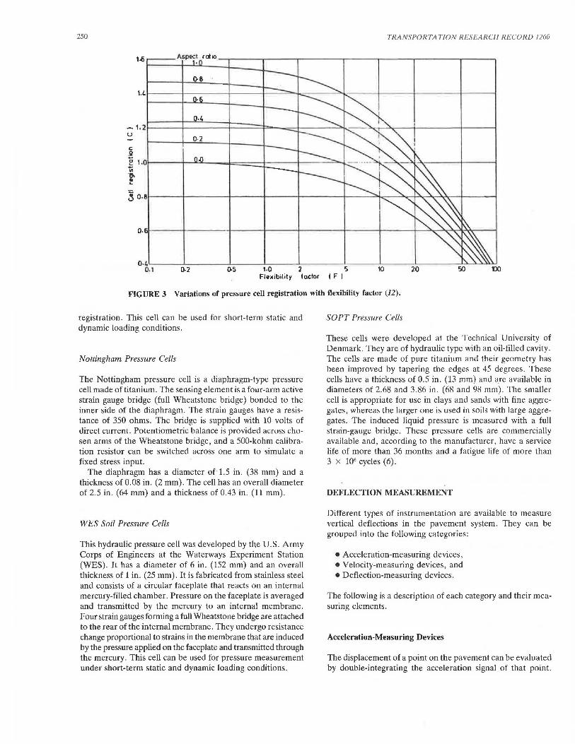
stress. This redistribution depends on the stiffness of the cell diaphragm as well as the ratio of cell thickness to its diameter (also called aspect ratio). Torry and Sparrow (12) performed a theoretical analysis for a pressure cell in a uniaxial stress field. They studied the effect of the flexibility factor on the pressure cell registration. The flexibility factor was defined by
Flexibility Factor
where
Es = Young's modulus of the soil material, Ee = Young's modulus of the cell material, d = diameter of the cell diaphragm, and t = thickness of the cell diaphragm.
(3)
Figure 3 shows the variation of pressure cell registration as a function of flexibility factor for different values of aspect ratio. The cell registration factor c represents the ratio of measured to actual stress values. According to this figure, cell registration remains nearly constant for a flexibility factor less than 1.0. In order to reduce the error in pressure measurements, cell registration close to 1 is desired. This condition occurs when the aspect ratio is as small as possible, less than 0.2, and the flexibility factor is less than 1.0.
Types of Pressure Cells
In the previous section, general design requirements for pressure cells were reviewed. In this section, the particular characteristics of some of the existing cells will be discussed. There are two basic types of embedded soil pressure cells: diaphragm cells and hydraulic cells.
The diaphragm cells consist of a stiff circular diaphragm supported by an integral stiff annular ring. This diaphragm is deflected by the applied external soil pressure. Electrical resistance strain gauges or some other type of strain measurement sensors are bonded to the interior face of the diaphragm (13). A diaphragm cell may have one or two independent active faces.
The hydraulic-type pressure cells consist of two circular (or in some cases, rectangular) steel plates welded together around their periphery to form a chamber or cavity. This chamber is filled with some type of de-aired liquid such as mercury. The total stress acting on the faceplates is balanced by an equal pressure induced in the internal liquid. This type of cell provides average soil pressure.
TRRLILVDT Pressure Cell
The TRRL/L VDT pressure cell is a diaphragm-type pressure cell that uses an L VDT to measure deflection of the diaphragm under soil pressure. The L VDT core fitted to one diaphragm can be screwed to its null position in the L VDT body attached to the other diaphragm. The cell is then sealed and maintained at this position under zero pressure. A thick annular ring reduces the effect of lateral stress on the cell
250 TRANSPORTATION RESEARCH RECORD 1260
().8
o.~l--~~....L~~~~.J..._~~---'-~~~.l--~~~---'-~~~--'-~~---'~~~~--'-'...__,~~
0.1 0.2 Q.5 1.0 2 5 10 20 50 1lO Fl11)(ibility factor I F I
FIGURE 3 Variations of pressure cell registration with flexibility factor (12).
registration. This cell can be used for short-term static and dynamic loading conditions.
Nottingham Pressure Cells
The Nottingham pressure cell is a diaphragm-type pressure cell made of titanium. The sensing element is a four-arm active strain gauge bridge (full Wheatstone bridge) bonded to the inner side of the diaphragm. The strain gauges have a resistance of 350 ohms. The bridge is supplied with 10 volts of direct current. Potentiometric balance is provided across chosen arms of the Wheatstone bridge, and a 500-kohm calibration resistor can be switched across one arm to simulate a fixed stress input.
The diaphragm has a diameter of 1.5 in. (38 mm) and a thickness of 0.08 in. (2 mm). The cell has an overall diameter of 2.5 in. (64 mm) and a thickness of 0.43 in. (11 mm).
WES Soil Pressure Cells
This hydraulic pressure cell was developed by the U.S. Army Corps of Engineers at the Waterways Experiment Station (WES). It has a diameter of 6 in. (152 mm) and an overall thickness of l in. (25 mm). It is fabricated from stainless steel and consists of a circular faceplate that reacts on an internal mercury-filled chamber. Pressure on the faceplate is averaged and transmitted by the mercury to an internal membrane. Four strain gauges forming a full Wheatstone bridge are attached to the rear of the internal membrane. They undergo resistance change proportional to strains in the membrane that are induced by the pressure applied on the faceplate and transmitted through the mercury. This cell can be used for pressure measurement under short-term static and dynamic loading conditions.
SOPT Pressure Cells
These cells were developed at the Technical University of Denmark. They are of hydraulic type with an oil-filled cavity. The cells are made of pure titanium and their geometry has been improved by tapering the edges at 45 degrees. These cells have a thickness of 0.5 in. (13 mm) and a.re available in diameters of 2.68 and 3.86 in. (68 and 98 mm). The smaller cell is appropriate for use in clays and sands with fine aggregates, whereas the larger one is used in soils with large aggregates. The induced liquid pressure is measured with a full strain-gauge bridge. These pressure cells are commercially available and, according to the manufacturer, have a service life of more than 36 months and a fatigue life of more than 3 x 10⁶ cycles ( 6).
DEFLECTION MEASUREMENT
Different types of instrumentation are available to measure vertical deflections in the pavement system. They can be grouped into the following categories:
• Acceleration-measuring devices, •Velocity-measuring devices, and • Deflection-measuring devices.
The following is a description of each category and their measuring elements.
Acceleration-Measuring Devices
The displacement of a point on the pavement can be evaluated by double-integrating the acceleration signal of that point.
Tabatabaee and Sebaaly
Thus accelerometers can be used to measure pavement deflection. The output signal of an accelerometer can be integrated by electrical hardware or through software after digitization. Accelerometers can only measure dynamic instantaneous displacement because the point of measurement should experience a certain level of excitation. Accelerometers do not need any reference points; their reference is enclosed within the actual unit. Therefore, they can be used as a stand-alone unit on the surface or embedded into the pavement layers at any depth .
Velocity-Measuring Devices
The velocity signal of the pavement surface under a given dynamic load can be integrated once to generate the deflection time response. Therefore, geophones can be used to measure pavement deflections. A mass is attached to a spring with support to the pavement surface. A wire (or coil) attached to the mass becomes part of the total mass. When the pavement surfaces moves, the magnet and support also move. The geophone frequency is defined as the frequency of oscillation in the theoretical case of no damping. This frequency is controlled by the ratio of total mass to spring constant. When the measurement frequency becomes smaller, this ratio should be increased. Therefore, a larger mass should be used for lowfrequency measurements. The use of a larger mass would also increase the overall dimensions and unit price of the geophone.
Geophones are very rugged and can withstand high temperatures of hot mix asphalt. Geophones can measure only dynamic transient deflections, but do not need any reference points.
Deflection-Measuring Devices
These devices measure the actual deflection, and hence the signal does not need to be integrated. The majority of these devices use a linear variable differential transformer (L VDT) to measure both the static and transient dynamic deflections. Some deflection devices, called single-layer deflectometers (SLDs), measure the deflection of a given layer of the pavement system. The most sophisticated type of deflectionmeasuring device , called multidepth deflectometer (MDD) , can measure the deflection at various points throughout the pavement depth.
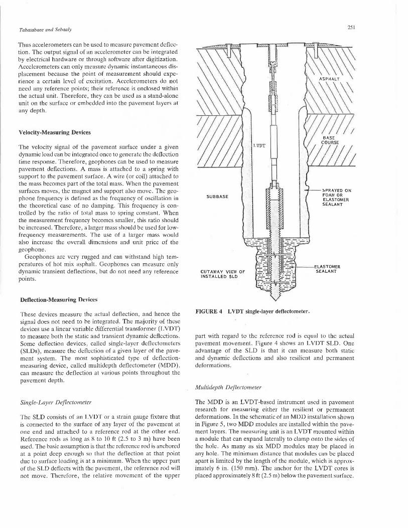
Single-Layer Deflectometer
The SLD consists of an L VDT or a strain gauge fixture that is connected to the surface of any layer of the pavement at one end and attached to a reference rod at the other end. Reference rods as long as 8 to 10 ft (2.5 to 3 m) have been used. The basic assumption is that the reference rod is anchored at a point deep enough so that the deflection at that point due to surface loading is at a minimum . When the upper part of the SLD deflects with the pavement, the reference rod will not move. Therefore, the relative movement of the upper
SUB BASE
CUTAWAY VIEW OF INSTALLED SLD
LVDT
251
~PRAYED ON FOAM OR ELASTOMER SEALANT
~~--ELASTOMER SEALANT
FIGURE 4 LVDT single-layer deflectometer.
part with regard to the reference rod is equal to the actual pavement movement. Figure 4 shows an LVDT SLD. One advantage of the SLD is that it can measure both static and dynamic deflections and also resilient and permanent deformations.
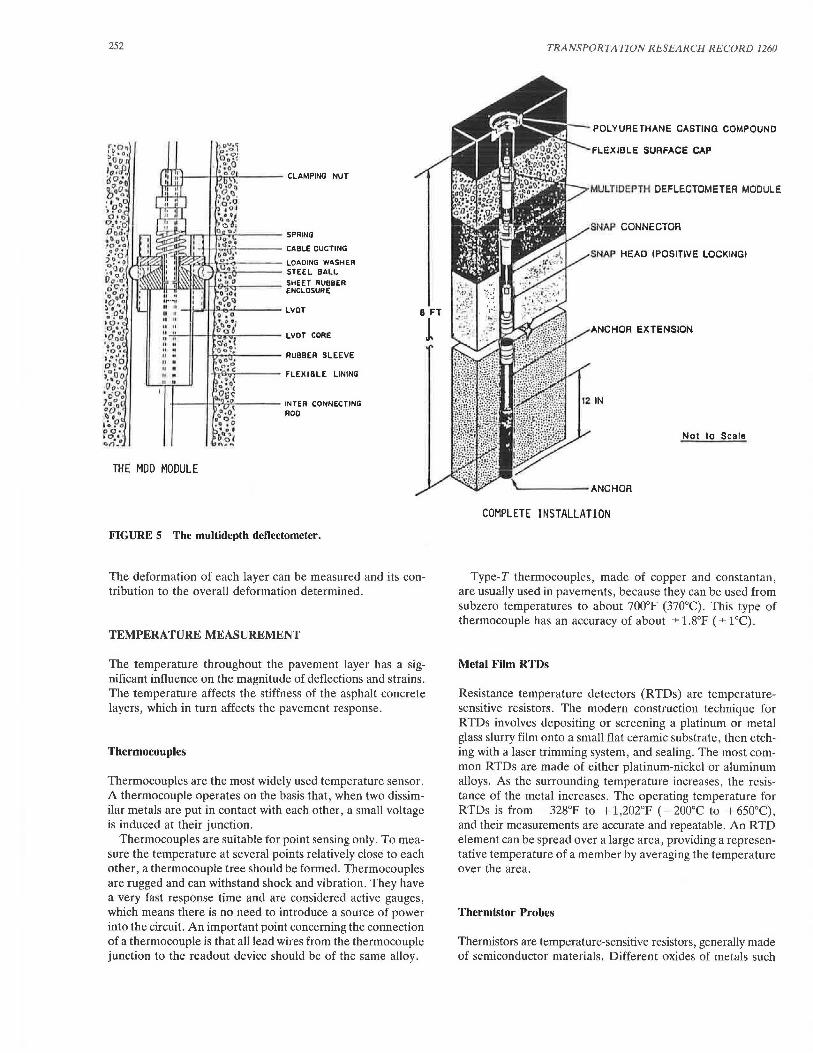
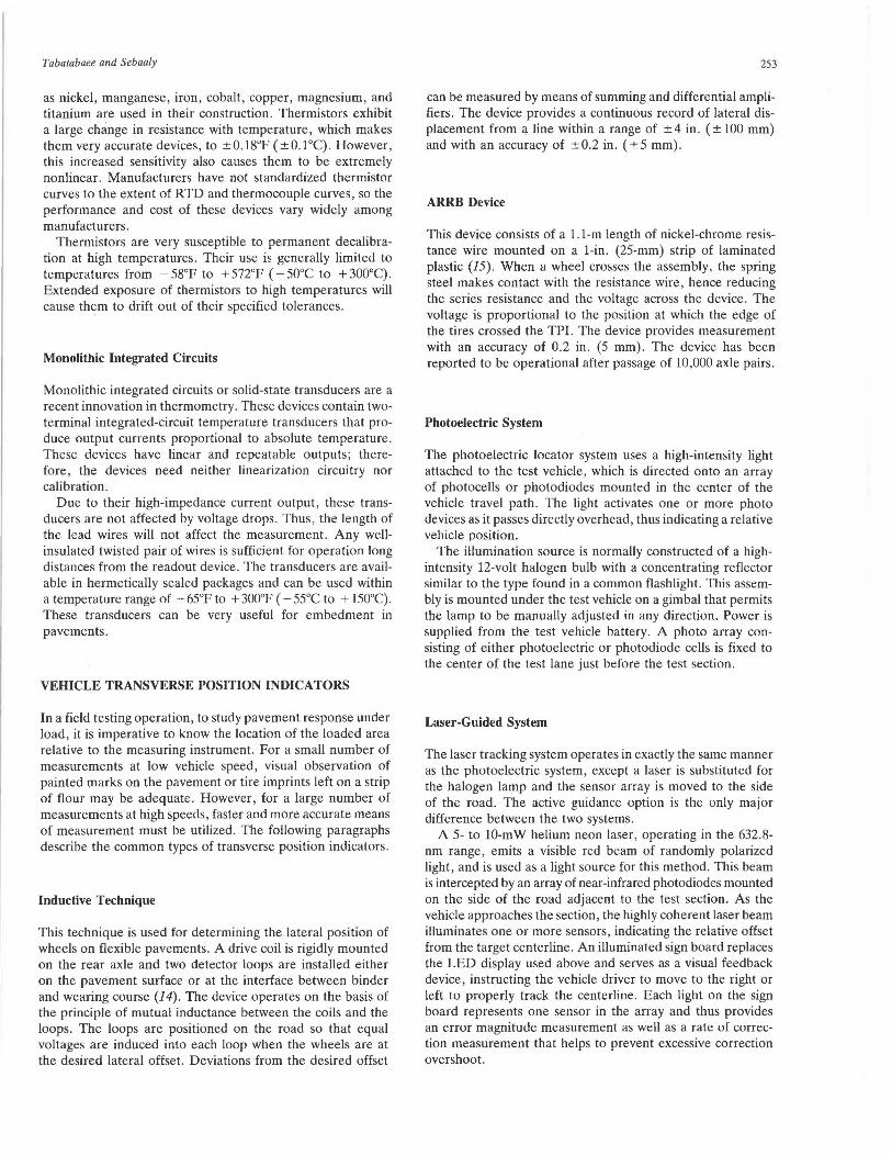
Multidepth Deflectometer
The MDD is an L VDT-based instrument used in pavement research for measuring either the resilient or permanent deformations. In the schematic of an MDD installation shown in Figure 5, two MDD modules are installed within the pavement layers. The measuring unit is an L VDT mounted within a module that can expand laterally to clamp onto the sides of the hole. As many as six MOD modules may be placed in any hole . The minimum distance that modules can be placed apart is limited by the length of the module, which is approximately 6 in. (150 mm). The anchor for the LVDT cores is placed approximately 8 ft (2.5 m) below the pavement surface.
252
?-irr-.r-H~iT----- SPRING
~--TV<ef'~--- CABLE OUCTING
tz~ili-'t~...,.._ ___ LOAOING WASHER _,,__, ____ STEEL BALL
l.~>=!H,.,,,.,f!»ll l-tli~..----- ~~~~Js~~~BER
" " II II
_._ _ __.,_._"-""---- INTER CONNECTING
ROO
THE MOD MODULE
FIGURE 5 The multidepth deflectometer.
The deformation of each layer can be measured and its contribution to the overall deformation determined.
TEMPERATURE MEASUREMENT
The temperature throughout the pavement layer has a significant influence on the magnitude of deflections and strains. The temperature affects the stiffness of the asphalt concrete layers, which in turn affects the pavement response.
Thermocouples
Thermocouples are the most widely used temperature sensor. A thermocouple operates on the basis that, when two dissimilar metals are put in contact with each other, a small voltage is induced at their junction.
Thermocouples are suitable for point sensing only. To measure the temperature at several points relatively close to each other, a thermocouple tree should be formed. Thermocouples are rugged and can withstand shock and vibration. They have a very fast response time and are considered active gauges, which means there is no need to introduce a source of power into the circuit. An important point concerning the connection of a thermocouple is that all lead wires from the thermocouple junction to the readout device should be of the same alloy.
TRANSPORTATION RESEARCH RECORD 1260
POLYURETHANE CASTING COMPOUND
FLEXIBLE SURFACE CAP
MULTIDEPTH OEFLECTOMETER MODULE
SNAP CONNECTOR
SNAP HEAD !POSITIVE LOCKING!
ANCHOR EXTENSION
Not to Scala
------ANCHOR
COMPLETE INSTALLATION
Type-T thermocouples, made of copper and constantan, are usually used in pavements, because they can be used from subzero temperatures to about 700°F (370°C). This type of thermocouple has an accuracy of about ± l.8°F ( ± 1°C).
Metal Film RTDs
Resistance temperature detectors (RTDs) are temperaturesensitive resistors. The modern construction technique for RTDs involves depositing or screening a platinum or metal glass slurry film onto a small flat ceramic substrate, then etching with a laser trimming system, and sealing. The most common RTDs are made of either platinum-nickel or aluminum alloys. As the surrounding temperature increases, the resistance of the metal increases. The operating temperature for RTDs is from 328°F to 1 l ,202°F ( 200°c to + 650°C), and their measurements are accurate and repeatable. An RTD element can be spread over a large area, providing a representative temperature of a member by averaging the temperature over the area.
Thermistor Probes
Thermistors are temperature-sensitive resistors, generally made of semiconductor materials. Different oxides of metals such
Tabatabaee and Sebaaly
as nickel, manganese, iron, cobalt, copper, magnesium, and titanium are used in their construction. Thermistors exhibit a large change in resistance with temperature, which makes them very accurate devices, to ±O.l8°F ( ±0.1°C). However, this increased sensitivity also causes them to be extremely nonlinear. Manufacturers have not standardized thermistor curves to the extent of RTD and thermocouple curves, so the performance and cost of these devices vary widely among manufacturers.
Thermistors are very susceptible to permanent decalibration at high temperatures. Their use is generally limited to temperatures from - 58°F to + 572°F ( - 50°C to + 300°C). Extended exposure of thermistors to high temperatures will cause them to drift out of their specified tolerances.
Monolithic Integrated Circuits
Monolithic integrated circuits or solid-state transducers are a recent innovation in thermometry. These devices contain twoterminal integrated-circuit temperature transducers that produce output currents proportional to absolute temperature. These devices have linear and repeatable outputs; therefore, the devices need neither linearization circuitry nor calibration.
Due to their high-impedance current output, these transducers are not affected by voltage drops. Thus, the length of the lead wires will not affect the measurement. Any wellinsulated twisted pair of wires is sufficient for operation long distances from the readout device. The transducers are available in hermetically sealed packages and can be used within a temperature range of - 65°F to + 300°F ( - 55°C to + 150°C). These transducers can be very useful for embedment in pavements.
VEHICLE TRANSVERSE POSITION INDICATORS
In a field testing operation, to study pavement response under load, it is imperative to know the location of the loaded area relative to the measuring instrument. For a small number of measurements at low vehicle speed, visual observation of painted marks on the pavement or tire imprints left on a strip of flour may be adequate. However, for a large number of measurements at high speeds, faster and more accurate means of measurement must be utilized. The following paragraphs describe the common types of transverse position indicators .
Inductive Technique
This technique is used for determining the lateral position of wheels on flexible pavements. A drive coil is rigidly mounted on the rear axle and two detector loops are installed either on the pavement surface or at the interface between binder and wearing course (14). The device operates on the basis of the principle of mutual inductance between the coils and the loops. The loops are positioned on the road so that equal voltages are induced into each loop when the wheels are at the desired lateral offset. Deviations from the desired offset
253
can be measured by means of summing and differential amplifiers. The device provides a continuous record of lateral displacement from a line within a range of ± 4 in . ( ± 100 mm) and with an accuracy of ±0.2 in. (±5 mm).
ARRB Device
This device consists of a 1.1-m length of nickel-chrome resistance wire mounted on a 1-in. (25-mm) strip of laminated plastic (15) . When a wheel crosses the assembly, the spring steel makes contact with the resistance wire, hence reducing the series resistance and the voltage across the device. The voltage is proportional to the position at which the edge of the tires crossed the TPI. The device provides measurement with an accuracy of 0.2 in. (5 mm). The device has been reported to be operational after passage of 10,000 axle pairs.
Photoelectric System
The photoelectric locator system uses a high-intensity light attached to the test vehicle, which is directed onto an array of photocells or photodiodes mounted in the center of the vehicle travel path. The light activates one or more photo devices as it passes directly overhead, thus indicating a relative vehicle position.
The illumination source is normally constructed of a highintensity 12-volt halogen bulb with a concentrating reflector similar to the type found in a common flashlight. This assembly is mounted under the test vehicle on a gimbal that permits the lamp to be manually adjusted in any direction. Power is supplied from the test vehicle battery. A photo array consisting of either photoelectric or photodiode cells is fixed to the center of the test Jane just before the test section.
Laser-Guided System
The laser tracking system operates in exactly the same manner as the photoelectric system, except a laser is substituted for the halogen lamp and the sensor array is moved to the side of the road. The active guidance option is the only major difference between the two systems.
A 5- to 10-mW helium neon laser, operating in the 632.8-nm range, emits a visible red beam of randomly polarized light, and is used as a light source for this method. This beam is intercepted by an array of near-infrared photodiodes mounted on the side of the road adjacent to the test section. As the vehicle approaches the section, the highly coherent laser beam illuminates one or more sensors, indicating the relative offset from the target centerline . An illuminated sign board replaces the LED display used above and serves as a visual feedback device, instructing the vehicle driver to move to the right or left to properly track the centerline. Each light on the sign board represents one sensor in the array and thus provides an error magnitude measurement as well as a rate of correction measurement that helps to prevent excessive correction overshoot.

254
Ultrasonic System
This method uses ultrasonic waves to judge distance. In operation, a sound pulse is transmitted from the edge of the test section toward the targeted vehicle and the return echo is detected and timed. The elapsed time between the two pulses is proportional to the vehicle distance. A target-to-transmitter distance of 10 ft (3 m) translates into a period of approximately 17.55 ms with a resolution of 0.12 in. (3.05 mm) over this range. Measurements can be made as far as 33 ft (10 m) away and still be accurate to VY'ithin 1 percent. A target board may be mounted on the test vehicle to obtain more accurate measurements.
SUMMARY AND RECOMMENDATIONS
It has been discussed that various types of strain gauges, pressure cells, deflection devices, temperature sensors, and vehicle transverse position indicators can be used to instrument flexible pavements. However, the individual design and operational characteristics of the gauges control the actual application of each gauge. The following represents a set of recommendations on the use of these gauges:
•The H-gauges can only be used in new constructions. If high temperatures and heavy loads are expected, the stiffness of the carrier strip may cause loosening of the anchor bars from the surrounding asphalt concrete materials. Therefore, under these circumstances, the strip material with the lowest modulus of elasticity should be selected (i.e., plastic strip should be used rather than aluminum).
• The laboratory compacted blocks and the asphalt mastic carrier blocks are only applicable for new construction . The major concern with this type of gauges is that when the carrier blocks softens due to high paving temperatures, the entire block might be deformed due to compaction forces . Therefore, it is not clear what kind of strains the deformed strain gauge will be recording.
• The instrumented core gauges can be installed in both new and old pavements. The process involves some disturbances of the aggregate and asphalt cement structure due to cutting and retrofitting of the instrumented core. The epoxy used to glue the gauges to the cores must be carefully selected with properties closely matching the asphalt concrete materials. The epoxy layer must be as thin as possible to avoid measuring the strains developed within the thick layer of epoxy. In addition, the strain gauges must be located over a representative range of aggregates and asphalt cement binder. Therefore, the length of the gauge must be at least three to four times the maximum size of aggregates. On the other hand, the longer the strain gauge the larger the area over which the strain is being averaged. Therefore, an optimum gauge length must be determined.
•The calibration of pressure cells presents a major drawback in using these gauges. It is almost impossible to replicate the field conditions in a laboratory set up. In situ calibration of the pressure cells may be a valid approach. This can be accomplished by loading the instrumented section with a nondestructive testing device such as the FWD, Dynaflect, or static truck load and monitoring the response of the pressure
TRA NSPORTA TION RESEARCH RECORD 1260
cell simultaneously . Use the surface deflections basin to backcalculate the layers moduli and use these moduli with an analysis model to predict the measured stresses at the location of the pressure cell. The relationship between the measured values and the calculated ones should provide the calibration curve for the embedded pressure cell. At the present time, there are no field performance data from either the hydraulictype or the diaphragm-type of pressure cell. However, the best expected accuracy of any type of pressure cells is around ± 20 percent. ~The L \'DT-typc strain gauges are the only type that can
be used to measure strains in subgrade soils. They can be installed in both new and old pavements. However, it is recommended that they are installed during construction if feasible. A fairly experienced technician is needed to conduct a successful installation. It is also recommended that the complete data acquisition system be connected during installation to ensure that the gauge is not driven outside its active range.
• The signals from the acceleration and velocity measuring devices require double and single integration, respectively, to obtain the actual pavement deflection signal. The accuracy of the integrated signal is highly dependent on the cutoff points and the level of noise in the raw signal. It has also been noted that the time and frequency domain integrations could result in completely different results. The velocity measuring devices suffer from another problem that is related to their frequency range. As the frequency range of the geophones becomes smaller, their actual size becomes larger. Currently, the land 2-Hz geophones have a 3-in. diameter and 5-in . height. In order to capture the entire deflection signal from a moving truck, it is necessary to use the low-frequency geophones, but their large physical size makes it impossible to embed them in the pavement layers .
• The deflection measuring devices can be installed into both new and old pavements. The SLD is simpler to design and install than the MDD. However, the use of the SLD involves greater disturbance of the pavement than the MDD. It will generally take three different SLDs at different locations to measure what a single MDD can measure at one location. Based on past experience with SLDs and MDDs, it is recommended that the L VDTs should be of the AC type and must be hermetically sealed to minimize the damage due to in situ moisture. The installation of an SLD can be accomplished by any competent technician, whereas the installation of the MDD requires a very well trained technician and special tools.
• All of the temperature sensors discussed in this paper have the required range for monitoring pavement temperatures. Thermocouples have been widely used in the area of pavement instrumentation. The solid state transducers provide a large linear range and may be used a lot easier than other sensors.
• All five different types of the vehicle transverse position indicators discussed in this paper are expected to provide adequate resolution for the purposes of pavement instrumentation activities. The best replicates of a loaded truck traveling at testing speeds between 20 and 50 mph are expected within ± 3 in. The resolution of any one of the discussed devices exceeds that by a large margin. Basically the ultrasonic and the laser systems are similar, except the laser-guided system may be a little more expensive .
Tabatabaee and Sebaaly
ACKNOWLEDGMENT
The authors would like to acknowledge the FHWA, which is providing the funds for the project.
REFERENCES
1. P. Sebaaly, N. Tabatabaee, and T. Scullion. Instrumentation for Flexible Pavements. Report FHWA-RD-89-084, FHWA, U.S. Department of Transportation, 1989.
2. J. F. Potter, H. C. Mayhew, and A. P. Mayo. Instrumentation of the Full Scale Experiment on Al Trunk Road at Conington, Huntingdonshire. Report LR 296, Road Research Laboratory, Crowthorne, Berkshire, England, 1969.
3. Organisation for Economic Cooperation and Development. FullScale Pavement Tests. Paris, 1985.
4. Organisation for Economic Cooperation and Development. Strain Measurements in Bituminous Layers. Paris, 1985.
5. P. Ulidtz. Pavement Analysis. Elsevier, 1987. 6. Dynatest 8000 FWD Test System. Dyna test Consulting, Inc., Ojai,
Calif., undated. 7. Pressure, Strain and Force Measurement Handbook and Ency
clopedia. Omega Engineering, Inc., Stamford, Conn., 1987. 8. A. J. G. Klomp and T. W. Niesman. Observed and Calculated
Strains at Various Depths in Asphalt Pavements. Proc., 2nd International Conference on the Structural Design of Asphalt Pavements, University of Michigan, Ann Arbor, 1967, pp. 671-688.
255
9. J. T. Christison, K. 0. Anderson, and B. P. Shields. In Situ Measurements of Strains and Deflections in a Full-Depth Asphaltic Concrete Pavement. Proc., Association of Asphalt Paving Technologists, Vol. 47, 1978, pp. 398-433.
10. D. A. Anderson, P. Sebaaly, N. Tabatabaee, R. Bonaquist, and C. Churilla. Pavement Testing Facility-Pavement Performance of the Initial Two Test Sections. Final Report FHWA/RD-88/060, FHWA, U.S. Department of Transportation, 1988.
11. M. Huhtala, J. Pihlajamiiki, and M. Pienimiiki. Effects of Tires and Tire Pressures on Road Pavements. In Transportation Research Record 1227, TRB, National Research Council, Washington, D.C., 1989.
12. A. C. Torry and R. W. Sparrow. The Influence of the Diaphragm Flexibility on the Performance of an Earth Pressure Cell. Journal of Scientific Instruments, Vol. 44, 1967, .PP· 781-785. . .
13. J. Dunnicliff. Geotechnical Instrumentation for Monitoring Field Performance. John Wiley, New York, 1988.
14. A. R. Halliday. An Inductive Technique for Determining the Lateral Position of Test Wheels on Roads. Supplementary Report 306, Transport and Road Research Laboratory, Crowthorne, Berkshire, England, 1977.
15. K. G. Sharp, R. A. K. Hannay, and D. W. Potter. A Device to Measure the Transverse Position of a Vehicle in a Traffic Stream. Proc., 14th Australian Road Research Board Conference, Part 8, Melbourne, Australia, 1988, pp. 196-206.
Publication of this paper sponsored by Committee on Applications of Emerging Technology.