State of the art concepts and verification strategies for ...
35
State of the art concepts and verification strategies for passive de-orbiting systems using deployable booms and membranes 17th of March 2015 Patric Seefeldt (Membrane Design/Qualification), Maciej Sznajder (Degradation) German Aerospace Center (DLR), Institute of Space Systems Martin Hillebrandt, Sebastian Meyer (Deployable Booms) DLR Institute of Composite Structures and Adaptive Systems www.DLR.de • Chart 1 • State of the Art and Verification • Patric Seefeldt • 17.03.15
Transcript of State of the art concepts and verification strategies for ...

State of the art concepts and verification
strategies for passive de-orbiting systems using
deployable booms and membranes 17th of March 2015
Patric Seefeldt (Membrane Design/Qualification), Maciej Sznajder (Degradation)
German Aerospace Center (DLR), Institute of Space Systems
Martin Hillebrandt, Sebastian Meyer (Deployable Booms)
DLR Institute of Composite Structures and Adaptive Systems
www.DLR.de • Chart 1 • State of the Art and Verification • Patric Seefeldt • 17.03.15

Content
Space Debris and Drag Augmentation Introduction
What can we learn from precursor projects?
• Applications for Deployable Membranes
• Membrane Stowing
• Membrane Design Aspects
• Materials and Space Environment
• Deployable Booms
Gossamer Structures Verification Strategies
www.DLR.de • Chart 2 • State of the Art and Verification • Patric Seefeldt • 17.03.15

Space Debris and Drag Augmentation
• Sharp increase due to Chinese anti-satellite missile test in 2007 and a
collision of two satellites (Iridium33 and Kosmos2251) in 2009
• Envisat orbiting at 790km altitude brings a risk of a new collision
• Deorbiting strategies are required, (one) solution is drag augmentation
ESA’s Deployable Membrane and ADEO Projects,
will be presented in the upcoming presentations
www.DLR.de • Chart 3 • State of the Art and Verification • Patric Seefeldt • 17.03.15
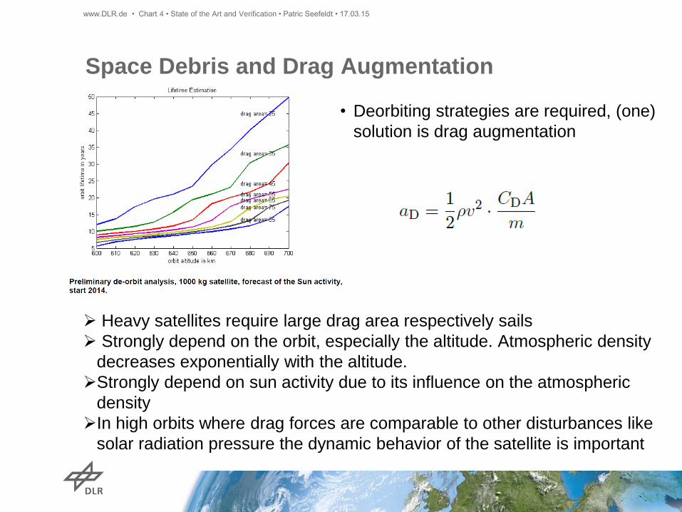
Space Debris and Drag Augmentation
Heavy satellites require large drag area respectively sails
Strongly depend on the orbit, especially the altitude. Atmospheric density
decreases exponentially with the altitude.
Strongly depend on sun activity due to its influence on the atmospheric
density
In high orbits where drag forces are comparable to other disturbances like
solar radiation pressure the dynamic behavior of the satellite is important
• Deorbiting strategies are required, (one)
solution is drag augmentation
www.DLR.de • Chart 4 • State of the Art and Verification • Patric Seefeldt • 17.03.15
Applications for Deployable Membranes
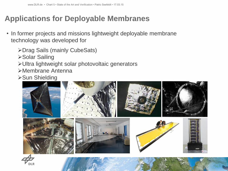
• In former projects and missions lightweight deployable membrane
technology was developed for
Drag Sails (mainly CubeSats)
Solar Sailing
Ultra lightweight solar photovoltaic generators
Membrane Antenna
Sun Shielding
www.DLR.de • Chart 5 • State of the Art and Verification • Patric Seefeldt • 17.03.15
Transferable Design Aspects for Drag Sails
• Drag Sail Projects (mainly CubeSats)
Stowing and deployment strategies (scalability from CubeSats is
difficult)
Materials
Membrane design
• Solar Sailing
Stowing and deployment strategies
Materials
Membrane design
• Ultra lightweight solar photovoltaic generators
Protective coatings
• Membrane Antenna
Load introduction, surface accuracy
www.DLR.de • Chart 6 • State of the Art and Verification • Patric Seefeldt • 17.03.15

Membrane Stowing
www.DLR.de • Chart 7 • State of the Art and Verification • Patric Seefeldt • 17.03.15

Space Debris
Membrane Stowing
www.DLR.de • Chart 8 • State of the Art and Verification • Patric Seefeldt • 17.03.15
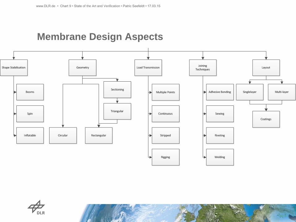
Membrane Design Aspects
www.DLR.de • Chart 9 • State of the Art and Verification • Patric Seefeldt • 17.03.15

Membrane Design Aspects
www.DLR.de • Chart 10 • State of the Art and Verification • Patric Seefeldt • 17.03.15
Materials
• Most projects considered coated polyimide films (Kapton or Upilex) due to good
mechanical behavior and thermal resistance
• Vacuum Deposited Aluminum (VDA) on polyimide is a standard product and was
chosen in many former projects. Additional protective and thermo-optical coatings
were considered especially for photovoltaics (SiO2) and are used for various MLI
materials.
• Coatings are required as protection against space environment and for thermal
design
• Coatings need to be robust in order to stow the membranes
www.DLR.de • Chart 11 • State of the Art and Verification • Patric Seefeldt • 17.03.15

Space Environment in Low Earth Orbits (200 .. ~700 km)
Experiments (e.g. MISSE) performed under real space conditions
Large literature database of many degraded materials.
Preliminary material selection and characterization
• High concentration of Atomic Oxygen
Generated by solar radiation of
wavelength of about 243 nm,
Impact energy of 5 eV
• High energetic EMR radiation
Bond braking e.g. C-C, C-O
(especially hazard to polyimide films)
• Flux of solar p+/e- is negligible small
comparing to the AO flux.
www.DLR.de • Chart 12 • State of the Art and Verification • Patric Seefeldt • 17.03.15
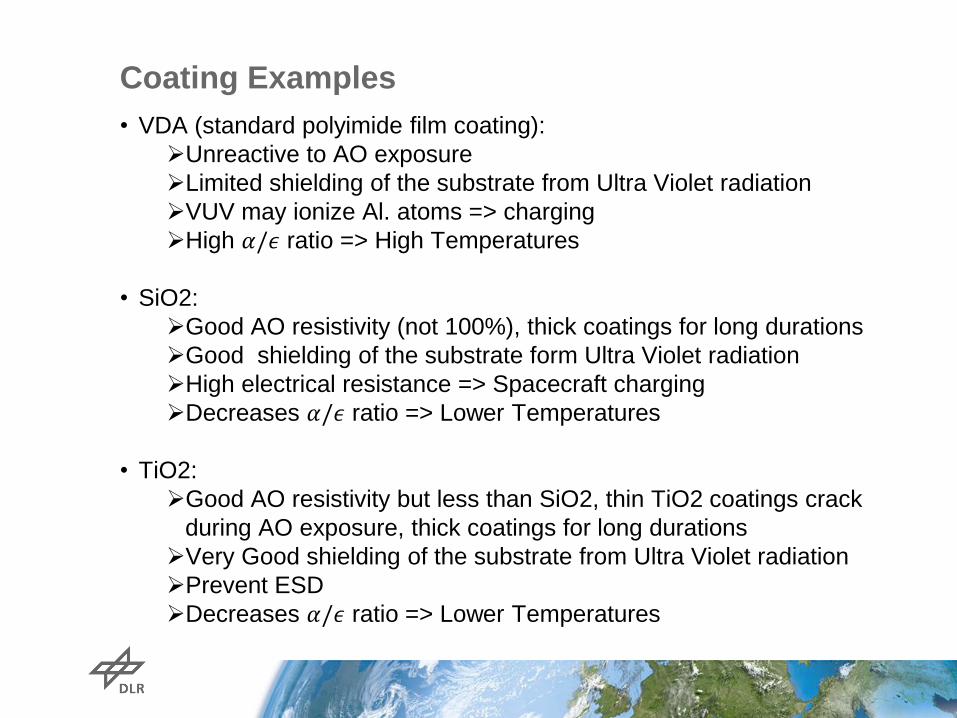
Coating Examples
• VDA (standard polyimide film coating):
Unreactive to AO exposure
Limited shielding of the substrate from Ultra Violet radiation
VUV may ionize Al. atoms => charging
High 𝛼/𝜖 ratio => High Temperatures
• SiO2:
Good AO resistivity (not 100%), thick coatings for long durations
Good shielding of the substrate form Ultra Violet radiation
High electrical resistance => Spacecraft charging
Decreases 𝛼/𝜖 ratio => Lower Temperatures
• TiO2:
Good AO resistivity but less than SiO2, thin TiO2 coatings crack
during AO exposure, thick coatings for long durations
Very Good shielding of the substrate from Ultra Violet radiation
Prevent ESD
Decreases 𝛼/𝜖 ratio => Lower Temperatures

Deployable Boom Technologies
Strain Energy
- Flexible structures
- Stowage by elastic
material
deformation
- Deployment by
stored strain energy
Inflatable
- Thin walled, highly
deformable shells
- Stowage by shell
folding
- Deployment by
inflation gas
- Rigidization may be
necessary
Articulated
- Rigid structural
members
- Stowage by use of
hinges
- Deployment by
additional
mechanism
Telescopic
- Segmented rigid
shell structure
- Stowage by use of
telescopic
segments
- Deployment by
additional
mechanism
Courtesy of University
of Surrey
Courtesy of ATK/ABLE
Engineering
Courtesy of Northrop Grumman
www.DLR.de • Chart 16 • State of the Art and Verification • Patric Seefeldt • 17.03.15

Strain Energy Deployment
- Thin-walled shell booms or trusses
with flexible members
- Deformation of the structure within
the elastic region of the material
- Maximum elastic strain limits
shell/rod thickness
- Deployment by stored strain energy
- Deployment may require support and
control by additional mechanism
Four longeron deployable CoilABLE truss (Courtesy of
ATK/ABLE Engineering)
Deployed De-Orbit Sail
drag sail using DLRS
CFRP boom technology
Bi-stable CFRP-booms
(Courtesy of RolaTube)
www.DLR.de • Chart 17 • State of the Art and Verification • Patric Seefeldt • 17.03.15

Inflatable Structures
- Tubular structures made of
laminated foils or thin walled
composites allowing plastic
deformation (thermoplastic or
uncured resins)
- Stowage by membrane-like folding
of the structure
- Gas-tight tubular structure allows
deployment by inflation
- Rigidization mechanism required
to maintain structural stability after
venting of the inflation gas
Inflatable Aluminum laminate
boom of Inflatesail (Courtesy
of University of Surrey)
Inflatable Sub-TG boom sample for
the Team Encounter Solar Sail
(Courtesy of L’Garde)
www.DLR.de • Chart 18 • State of the Art and Verification • Patric Seefeldt • 17.03.15

Articulated Structures
- Trusses or linkages with rigid
structural members connected by
hinges
- Deployment by springs at the
hinges or additional mechanisms
like motor driven cable/pulley
systems
- Latches may be required to lock
hinges in deployed state
dragNET de-orbit system using pantograph type deployable booms
for support of the sails (Courtesy of MMA Design) ADAM truss developed by ATK/ABLE Engineering
(O. Stohlman, “Repeatability of joint-dominated
deployable masts”, PhD-Thesis, Caltech, 2011)
www.DLR.de • Chart 19 • State of the Art and Verification • Patric Seefeldt • 17.03.15

Telescopic Structures
- Segmented, telescopic
structure made of rigid
elements with mainly tubular
cross-section
- Linear deployment driven by
additional mechanism
Telescopic composite mast deployed by an internal metal STEM boom
(Courtesy of Northrop Grumman)
www.DLR.de • Chart 20 • State of the Art and Verification • Patric Seefeldt • 17.03.15

Boom Evaluation Criteria
• Boom evaluation criteria for de-orbiting applications:
- Stowage Volume, Mass (including deployment mechanisms), Structural
performance (stiffness, strength), Scalability, Long term stowage capability,
Complexity, MMOD resistance, Thermal characteristics, Material degradation
• Evaluation of entire boom categories is necessarily defective as properties
among representatives of the same category may vary strongly.
Therefore, individual evaluation of boom concepts is necessary.
Telescopic Boom
Criteria Sub-Criteria Weighing Factors CFRP-Boom Coilable Boom TRAC Boom BI-stable Booms STEM Boom In-orbit rigidizable boom Aluminium Laminate Boom Pantograph ADAM/FAST TELESCOPIC MAST MODEL 7301
(Northrop Grumman)
Load Case Bending Bending Strength 7 4 5 2 2 3 3 1 3 5 4
mass specific Bending Stiffness 7 3 5 4 3 3 3 3 3 5 4
Load Case Compression
mass specific
Axial Strength
(Slenderness Ratio >80)
7 3 5 4 3 3 3 3 3 5 4
Stowage Volume
(Slenderness Ratio >80)
8 4 4 4 5 4 3 4 2 2 1
Interfaces (Tip
deployment)
root 6 4 4 4 4 4 2 2 3 4 5
tip 4 2 3 2 2 2 2 2 3 3 5
intermediate 1 2 3 2 2 2 1 1 3 3 1
Deployment robustness Controlability of
deployment process
6 5 5 5 5 5 2 2 5 5 5
Load carrying capability
during deployment
6 3 3 3 2 3 1 1 4 5 4
Max. transmittable
Deployment Force from
boom to sail
6 3 2 3 3 3 1 1 4 5 4
Mass (including
mechanism)
5 4 4 4 5 4 3 3 3 3 2
Degradation Creep (Composite only) 7 3 4 3 3 3 5 5 5 5 5
System Complexity
(including mechanism)
5 4 3 4 5 4 3 3 4 2 3
Scalability (down and
up)
8 5 3 3 3 3 4 4 5 3 4
MMOD robustness stowed 7 5 4 5 5 5 1 1 4 4 5
deployed 7 5 4 5 5 5 5 5 4 4 5
TRL(1-9) 6 6 9 7 6 9 6 8 9 9 8
Development risk
within the ADEO
Consortium
10 4 1 2 2 2 1 1 2 1 1
Manufacturing
Capabilities within
ADEO Consortium
10 5 1 1 1 1 1 1 2 1 1
Costs 8 5 1 1 2 1 1 1 2 1 1
Intellectual Properties
Rights
5-own property
2-commercially
available
1-Availability unknown
8 5 2 1 2 2 1 1 1 2 2
ITAR 5-no ITAR restriction
1-ITAR restriction
10 5 1 1 5 1 5 5 5 1 1
SUM 613 463 436 487 444 377 378 500 474 464
Shape Memory Inflatable Booms Articulated Booms
www.DLR.de • Chart 21 • State of the Art and Verification • Patric Seefeldt • 17.03.15
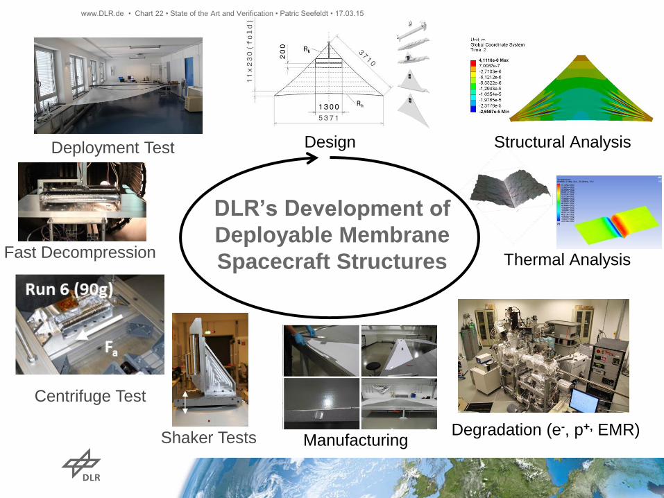
DLR’s Development of
Deployable Membrane
Spacecraft Structures
Manufacturing
Structural Analysis Design
Thermal Analysis
Degradation (e-, p+, EMR) Shaker Tests
Centrifuge Test
Fast Decompression
Deployment Test
www.DLR.de • Chart 22 • State of the Art and Verification • Patric Seefeldt • 17.03.15
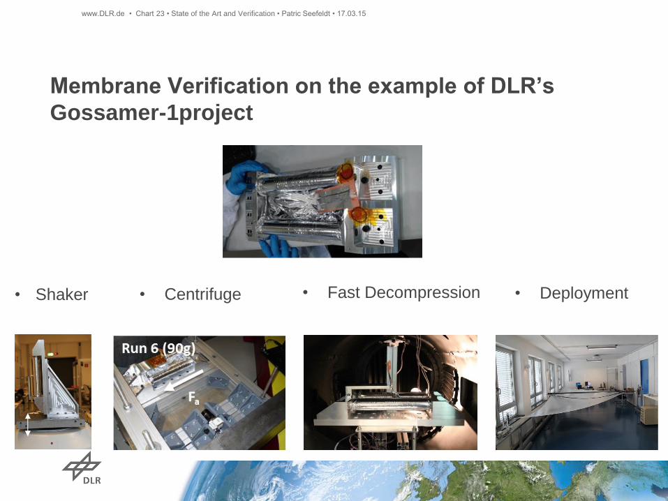
Membrane Verification on the example of DLR’s
Gossamer-1project
• Centrifuge • Fast Decompression • Deployment • Shaker
www.DLR.de • Chart 23 • State of the Art and Verification • Patric Seefeldt • 17.03.15

Verification – Shaker
Axis Frequency Level
X, Y 2 - 6 Hz
6 - 100 Hz
23 mm (0 to peak)
2.5 g
Z 2 - 6 Hz
6 - 100 Hz
23 mm (0 to peak)
3.5 g
sweep rate 2 octaves per minute (one upsweep)
www.DLR.de • Chart 24 • State of the Art and Verification • Patric Seefeldt • 17.03.15
Axis Peak
Frequency
Peak
Level
Overall
level
[grms]
X 100 Hz
120 Hz
7 g²/Hz
7 g²/Hz 19.89
Y 100 Hz
130 Hz
10 g²/Hz
10 g²/Hz 23.89
Z 190 Hz
215 Hz
7 g²/Hz
7 g²/Hz 28.53
duration 2 min per axis
• Sine
• Random
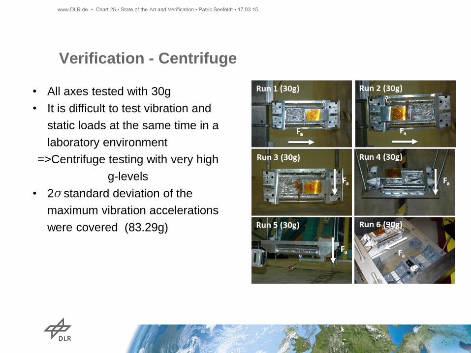
Verification - Centrifuge
• All axes tested with 30g
• It is difficult to test vibration and
static loads at the same time in a
laboratory environment
=>Centrifuge testing with very high
g-levels
• 2 standard deviation of the
maximum vibration accelerations
were covered (83.29g)
www.DLR.de • Chart 25 • State of the Art and Verification • Patric Seefeldt • 17.03.15
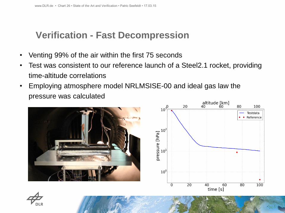
Verification - Fast Decompression
• Venting 99% of the air within the first 75 seconds
• Test was consistent to our reference launch of a Steel2.1 rocket, providing
time-altitude correlations
• Employing atmosphere model NRLMSISE-00 and ideal gas law the
pressure was calculated
www.DLR.de • Chart 26 • State of the Art and Verification • Patric Seefeldt • 17.03.15
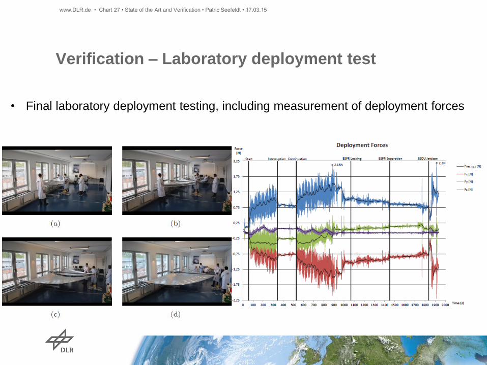
Verification – Laboratory deployment test
• Final laboratory deployment testing, including measurement of deployment forces
www.DLR.de • Chart 27 • State of the Art and Verification • Patric Seefeldt • 17.03.15
Verification – Further Aspects
• Microscope investigations, package verification (e.g. coatings)
• Degradation experiments (e.g. VUV and ATOX)
• Boom characterization (e.g. Stiffness, creeping)
• …..
www.DLR.de • Chart 28 • State of the Art and Verification • Patric Seefeldt • 17.03.15

Summary
www.DLR.de • Chart 29 • State of the Art and Verification • Patric Seefeldt • 17.03.15
State of the art review in the field of
Drag Sails, Solar Sails, Thin-film Photovoltaics, Membrane Antenna,
Sun Shielding
Summary membrane stowing strategies
Summary membrane design aspects
Space Environment in LEO and impact on Materials
Exemplarily three different coatings were presented (Al, SiO2, TiO2)
Membrane Verification
Qualification testing on the example of DLR’s Gossamer-1 Project
Shaker, Centrifuge, Fast Decompression and laboratory Deployment
Bibliography
www.DLR.de • Chart 30 • Deployable Membrane - SRR - State of the Art , Patric Seefeldt • 13.02.15

Bibliography
www.DLR.de • Chart 31 • Deployable Membrane - SRR - State of the Art , Patric Seefeldt • 13.02.15
Bibliography
www.DLR.de • Chart 32 • Deployable Membrane - SRR - State of the Art , Patric Seefeldt • 13.02.15

Bibliography
www.DLR.de • Chart 33 • Deployable Membrane - SRR - State of the Art , Patric Seefeldt • 13.02.15

Bibliography
www.DLR.de • Chart 34 • Deployable Membrane - SRR - State of the Art , Patric Seefeldt • 13.02.15

Bibliography
www.DLR.de • Chart 35 • Deployable Membrane - SRR - State of the Art , Patric Seefeldt • 13.02.15

Bibliography
www.DLR.de • Chart 36 • Deployable Membrane - SRR - State of the Art , Patric Seefeldt • 13.02.15
Bibliography
www.DLR.de • Chart 37 • Deployable Membrane - SRR - State of the Art , Patric Seefeldt • 13.02.15