STATE OF ARIZONA - azdeq.govstatic.azdeq.gov/pn/draft_permit_silverbell.pdf · STATE OF ARIZONA....
69
DRAFT PERMIT www.azdeq.gov STATE OF ARIZONA AQUIFER PROTECTION PERMIT NO. P-100510 PLACE ID 2867, LTF 64411 SIGNIFICANT AMENDMENT 1.0 AUTHORIZATION In compliance with the provisions of Arizona Revised Statutes (A.R.S.) Title 49, Chapter 2, Articles 1, 2 and 3, and Chapter 4 Arizona Administrative Code (A.A.C.) Title 18, Chapter 9, Articles 1 and 2, A. A. C. Title 18, Chapter 11, Article 4 and amendments thereto, and the conditions set forth in this permit, the Arizona Department of Environmental Quality (ADEQ) hereby authorizes Silver Bell Mining L.L.C. to operate the discharging facilities located at the Silver Bell Mine (SBM) site located approximately 17 miles west of Marana, Arizona, over groundwater of the Tucson Active Management Area (AMA) groundwater basin and the Pinal AMA groundwater basin. This permit becomes effective on the date of the Water Quality Division Director’s signature and shall be valid for the life of the facility (operational, closure, and post-closure periods), unless suspended or revoked pursuant to A.A.C. R18-9-A213. The permittee shall construct, operate and maintain the permitted facilities: 1. Following all the conditions of this permit including the design and operational information documented or referenced below, and 2. Such that Aquifer Water Quality Standards (AWQS) are not violated at the applicable point(s) of compliance (POC) set forth below, or if an AWQS for a pollutant has been exceeded in an aquifer at the time of permit issuance, that no additional degradation of the aquifer relative to that pollutant, and as determined at the applicable POC, occurs as a result of the discharge from the facility. 1.1 PERMITTEE INFORMATION Facility Name: Silver Bell Mining, L.L.C. Facility Address: 25000 W. Avra Valley Road Marana, Arizona 85653 County: Pima Annual Registration Fee Flow Rate 10,000,000 gallons per day Permittee: Silver Bell Mining, L.L.C. Permittee Address: 25000 W. Avra Valley Road Marana, Arizona 85653 Facility Contact: General Manager Emergency Phone No.: (520) 682-4203 Latitude/Longitude: 32 o 22' 56.0" N / 111 o 27' 43.0" W Legal Description: Township 11S, Range 08E, Sections 32, 33, and 34, and Township 12S, Range 08E, Sections 3, 4, 5, 10, 11, and 12, Gila and Salt River Baseline and Meridian 1.2 AUTHORIZING SIGNATURES ___________________________________ Trevor Baggiore, Director Water Quality Division Arizona Department of Environmental Quality Signed this _____day of _______________, 2017 THIS PERMIT SUPERCEDES ALL PREVIOUS PERMITS
Transcript of STATE OF ARIZONA - azdeq.govstatic.azdeq.gov/pn/draft_permit_silverbell.pdf · STATE OF ARIZONA....

DRAFT PERMIT www.azdeq.gov
STATE OF ARIZONA
AQUIFER PROTECTION PERMIT NO. P-100510 PLACE ID 2867, LTF 64411
SIGNIFICANT AMENDMENT 1.0 AUTHORIZATION In compliance with the provisions of Arizona Revised Statutes (A.R.S.) Title 49, Chapter 2, Articles 1, 2 and 3, and Chapter 4 Arizona Administrative Code (A.A.C.) Title 18, Chapter 9, Articles 1 and 2, A. A. C. Title 18, Chapter 11, Article 4 and amendments thereto, and the conditions set forth in this permit, the Arizona Department of Environmental Quality (ADEQ) hereby authorizes Silver Bell Mining L.L.C. to operate the discharging facilities located at the Silver Bell Mine (SBM) site located approximately 17 miles west of Marana, Arizona, over groundwater of the Tucson Active Management Area (AMA) groundwater basin and the Pinal AMA groundwater basin.
This permit becomes effective on the date of the Water Quality Division Director’s signature and shall be valid for the life of the facility (operational, closure, and post-closure periods), unless suspended or revoked pursuant to A.A.C. R18-9-A213. The permittee shall construct, operate and maintain the permitted facilities:
1. Following all the conditions of this permit including the design and operational information documented or referenced below, and
2. Such that Aquifer Water Quality Standards (AWQS) are not violated at the applicable point(s) of compliance (POC) set forth below, or if an AWQS for a pollutant has been exceeded in an aquifer at the time of permit issuance, that no additional degradation of the aquifer relative to that pollutant, and as determined at the applicable POC, occurs as a result of the discharge from the facility.
1.1 PERMITTEE INFORMATION
Facility Name: Silver Bell Mining, L.L.C. Facility Address: 25000 W. Avra Valley Road
Marana, Arizona 85653 County: Pima
Annual Registration Fee Flow Rate 10,000,000 gallons per day
Permittee: Silver Bell Mining, L.L.C. Permittee Address: 25000 W. Avra Valley Road
Marana, Arizona 85653
Facility Contact: General Manager Emergency Phone No.: (520) 682-4203
Latitude/Longitude: 32o 22' 56.0" N / 111o 27' 43.0" W
Legal Description: Township 11S, Range 08E, Sections 32, 33, and 34, and Township 12S, Range 08E, Sections 3, 4, 5, 10, 11, and 12, Gila and Salt River Baseline and Meridian
1.2 AUTHORIZING SIGNATURES
___________________________________ Trevor Baggiore, Director Water Quality Division Arizona Department of Environmental Quality Signed this _____day of _______________, 2017
THIS PERMIT SUPERCEDES ALL PREVIOUS PERMITS
DRAFT AQUIFER PROTECTION PERMIT NO. P- 100510 p. 2 of 69
2.0 SPECIFIC CONDITIONS [A.R.S. §§ 49-203(4), 49-241(A)]
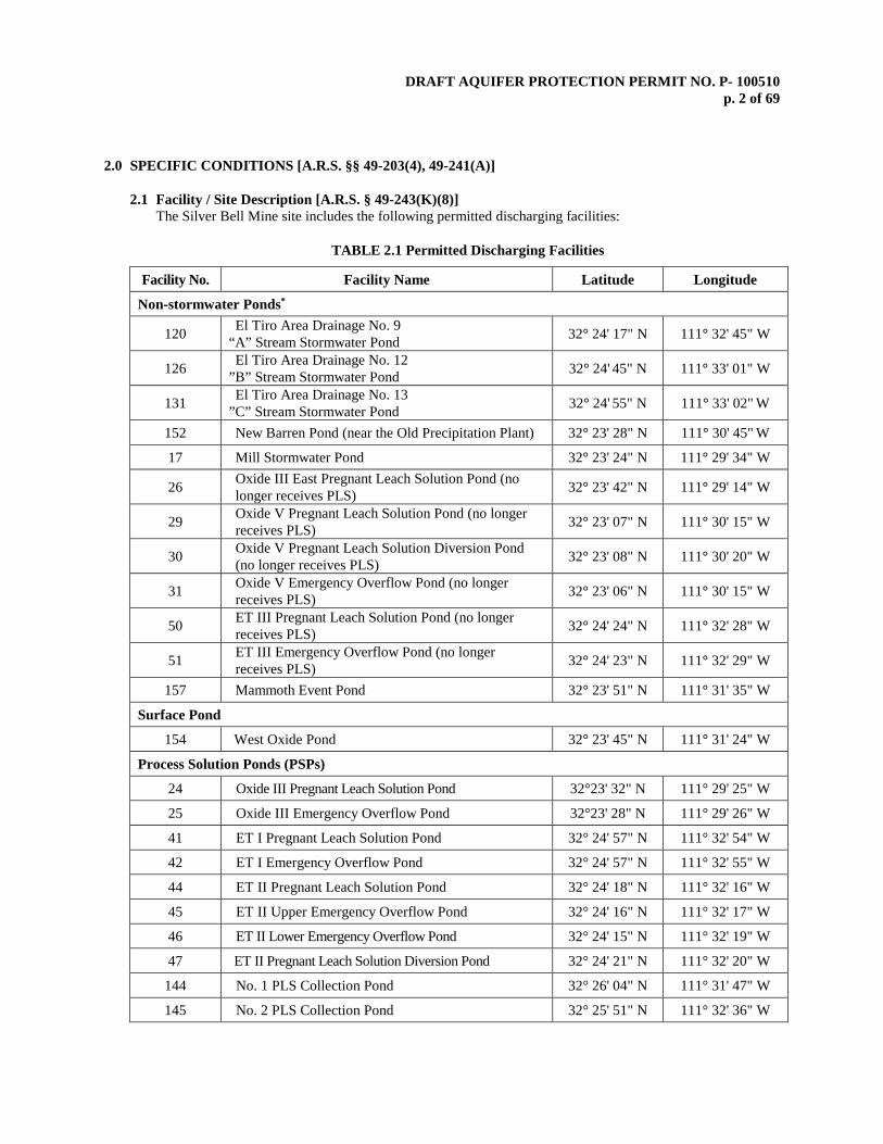
2.1 Facility / Site Description [A.R.S. § 49-243(K)(8)] The Silver Bell Mine site includes the following permitted discharging facilities:
TABLE 2.1 Permitted Discharging Facilities
Facility No. Facility Name Latitude Longitude
Non-stormwater Ponds*
120 El Tiro Area Drainage No. 9 “A” Stream Stormwater Pond 32° 24' 17" N 111° 32' 45" W
126 El Tiro Area Drainage No. 12 ”B” Stream Stormwater Pond 32° 24' 45" N 111° 33' 01" W
131 El Tiro Area Drainage No. 13 ”C” Stream Stormwater Pond 32° 24' 55" N 111° 33' 02" W
152 New Barren Pond (near the Old Precipitation Plant) 32° 23' 28" N 111° 30' 45" W
17 Mill Stormwater Pond 32° 23' 24" N 111° 29' 34" W
26 Oxide III East Pregnant Leach Solution Pond (no longer receives PLS) 32° 23' 42" N 111° 29' 14" W
29 Oxide V Pregnant Leach Solution Pond (no longer receives PLS) 32° 23' 07" N 111° 30' 15" W
30 Oxide V Pregnant Leach Solution Diversion Pond (no longer receives PLS) 32° 23' 08" N 111° 30' 20" W
31 Oxide V Emergency Overflow Pond (no longer receives PLS) 32° 23' 06" N 111° 30' 15" W
50 ET III Pregnant Leach Solution Pond (no longer receives PLS) 32° 24' 24" N 111° 32' 28" W
51 ET III Emergency Overflow Pond (no longer receives PLS) 32° 24' 23" N 111° 32' 29" W
157 Mammoth Event Pond 32° 23' 51" N 111° 31' 35" W
Surface Pond
154 West Oxide Pond 32° 23' 45" N 111° 31' 24" W
Process Solution Ponds (PSPs)
24 Oxide III Pregnant Leach Solution Pond 32°23' 32" N 111° 29' 25" W
25 Oxide III Emergency Overflow Pond 32°23' 28" N 111° 29' 26" W
41 ET I Pregnant Leach Solution Pond 32° 24' 57" N 111° 32' 54" W
42 ET I Emergency Overflow Pond 32° 24' 57" N 111° 32' 55" W
44 ET II Pregnant Leach Solution Pond 32° 24' 18" N 111° 32' 16" W
45 ET II Upper Emergency Overflow Pond 32° 24' 16" N 111° 32' 17" W
46 ET II Lower Emergency Overflow Pond 32° 24' 15" N 111° 32' 19" W
47 ET II Pregnant Leach Solution Diversion Pond 32° 24' 21" N 111° 32' 20" W
144 No. 1 PLS Collection Pond 32° 26' 04" N 111° 31' 47" W
145 No. 2 PLS Collection Pond 32° 25' 51" N 111° 32' 36" W
DRAFT AQUIFER PROTECTION PERMIT NO. P- 100510 p. 3 of 69
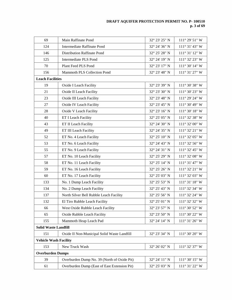
69 Main Raffinate Pond 32° 23' 25" N 111° 29' 51" W
124 Intermediate Raffinate Pond 32° 24' 36" N 111° 31' 43" W
146 Distribution Raffinate Pond 32° 25' 28" N 111° 31' 12" W
125 Intermediate PLS Pond 32° 24' 19" N 111° 32' 23" W
70 Plant Feed PLS Pond 32° 23' 17" N 111° 30' 14" W
156 Mammoth PLS Collection Pond 32° 23' 48" N 111° 31' 27" W
Leach Facilities
19 Oxide I Leach Facility 32° 23' 39" N 111° 30' 38" W
21 Oxide II Leach Facility 32° 23' 30" N 111° 30' 23" W
23 Oxide III Leach Facility 32° 23' 48" N 111° 29' 24" W
27 Oxide IV Leach Facility 32° 23' 45" N 111° 30' 49" W
28 Oxide V Leach Facility 32° 23' 16" N 111° 30' 18" W
40 ET I Leach Facility 32° 25' 05" N 111° 32' 38" W
43 ET II Leach Facility 32° 24' 30" N 111° 32' 00" W
49 ET III Leach Facility 32° 24' 35" N 111° 32' 21" W
52 ET No. 4 Leach Facility 32° 25' 10" N 111° 32' 05" W
53 ET No. 6 Leach Facility 32° 24' 43" N 111° 32' 56" W
55 ET No. 9 Leach Facility 32° 24' 31" N 111° 32' 45" W
57 ET No. 10 Leach Facility 32° 25' 29" N 111° 32' 08" W
58 ET No. 11 Leach Facility 32° 25' 14" N 111° 31' 47" W
59 ET No. 16 Leach Facility 32° 25' 26" N 111° 32' 21" W
60 ET No. 17 Leach Facility 32° 25' 03" N 111° 32' 03" W
133 No. 1 Dump Leach Facility 32º 25' 53" N 111º 31' 18" W
134 No. 2 Dump Leach Facility 32º 25' 43" N 111º 32' 34" W
137 North Silver Bell Rubble Leach Facility 32º 25' 56" N 111º 32' 24" W
132 El Tiro Rubble Leach Facility 32º 25' 01" N 111º 32' 32" W
66 West Oxide Rubble Leach Facility 32º 23' 57" N 111º 30' 52" W
65 Oxide Rubble Leach Facility 32º 23' 50" N 111º 30' 22" W
155 Mammoth Heap Leach Pad 32º 24' 14" N 111º 31' 26" W
Solid Waste Landfill
151 Oxide II Non-Municipal Solid Waste Landfill 32º 23' 34" N 111º 30' 20" W
Vehicle Wash Facility
153 New Truck Wash 32º 26' 02" N 111º 32' 37" W
Overburden Dumps
39 Overburden Dump No. 39 (North of Oxide Pit) 32° 24' 11" N 111° 30' 15" W
61 Overburden Dump (East of East Extension Pit) 32° 25' 03" N 111° 31' 22" W
DRAFT AQUIFER PROTECTION PERMIT NO. P- 100510 p. 4 of 69
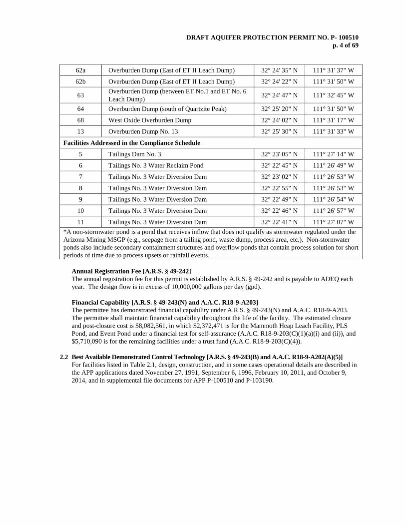
62a Overburden Dump (East of ET II Leach Dump) 32° 24' 35" N 111° 31' 37" W
62b Overburden Dump (East of ET II Leach Dump) 32° 24' 22" N 111° 31' 50" W
63 Overburden Dump (between ET No.1 and ET No. 6 Leach Dump) 32° 24' 47" N 111° 32' 45" W
64 Overburden Dump (south of Quartzite Peak) 32° 25' 20" N 111° 31' 50" W
68 West Oxide Overburden Dump 32° 24' 02" N 111° 31' 17" W
13 Overburden Dump No. 13 32° 25' 30" N 111° 31' 33" W
Facilities Addressed in the Compliance Schedule
5 Tailings Dam No. 3 32° 23' 05" N 111° 27' 14" W
6 Tailings No. 3 Water Reclaim Pond 32° 22' 45" N 111° 26' 49" W
7 Tailings No. 3 Water Diversion Dam 32° 23' 02" N 111° 26' 53" W
8 Tailings No. 3 Water Diversion Dam 32° 22' 55" N 111° 26' 53" W
9 Tailings No. 3 Water Diversion Dam 32° 22' 49" N 111° 26' 54" W
10 Tailings No. 3 Water Diversion Dam 32° 22' 46" N 111° 26' 57" W
11 Tailings No. 3 Water Diversion Dam 32° 22' 41" N 111° 27' 07" W *A non-stormwater pond is a pond that receives inflow that does not qualify as stormwater regulated under the Arizona Mining MSGP (e.g., seepage from a tailing pond, waste dump, process area, etc.). Non-stormwater ponds also include secondary containment structures and overflow ponds that contain process solution for short periods of time due to process upsets or rainfall events.
Annual Registration Fee [A.R.S. § 49-242] The annual registration fee for this permit is established by A.R.S. § 49-242 and is payable to ADEQ each year. The design flow is in excess of 10,000,000 gallons per day (gpd). Financial Capability [A.R.S. § 49-243(N) and A.A.C. R18-9-A203] The permittee has demonstrated financial capability under A.R.S. § 49-243(N) and A.A.C. R18-9-A203. The permittee shall maintain financial capability throughout the life of the facility. The estimated closure and post-closure cost is $8,082,561, in which $2,372,471 is for the Mammoth Heap Leach Facility, PLS Pond, and Event Pond under a financial test for self-assurance (A.A.C. R18-9-203(C)(1)(a)(i) and (ii)), and $5,710,090 is for the remaining facilities under a trust fund (A.A.C. R18-9-203(C)(4)).
2.2 Best Available Demonstrated Control Technology [A.R.S. § 49-243(B) and A.A.C. R18-9-A202(A)(5)]
For facilities listed in Table 2.1, design, construction, and in some cases operational details are described in the APP applications dated November 27, 1991, September 6, 1996, February 10, 2011, and October 9, 2014, and in supplemental file documents for APP P-100510 and P-103190.
DRAFT AQUIFER PROTECTION PERMIT NO. P- 100510 p. 5 of 69
2.2.1 Engineering Design
Engineering design features representing the primary discharge control technologies for each discharging facility are outlined in Table 4.1 with details of facility design, construction, and operational details.
2.2.2 Site-specific Characteristics Local geologic and hydrologic conditions for the SBM Site were evaluated and included in the SBM APP applications and subsequent submittals. Extensive packer testing for hydrologic transmissivity of each major rock type is reported along with their attenuation characteristics for fate and transport consideration. These data along with the practice of clearing and excavation down to bedrock were major considerations for engineering and hydrologic design of potentially discharging facilities. Efficiency of design using site-specific characteristics will be monitored through a program of hydrologic monitoring.
2.2.2.1 Leach Dumps and Pregnant Leach Solution (PLS) Ponds
The existing facilities most directly involved with potential discharge of pollutants to the groundwater are the leach dumps and PLS ponds. Packer tests performed in test holes throughout the site indicate low hydraulic conductivity for the underlying bedrock. This, coupled with the sloping ground surface under the dump for rapid drainage at the bottom, serves to minimize loss of PLS from the leach dumps.
The PLS ponds were excavated into solid bedrock of similar low hydraulic conductivity and over time an accumulation of very fine material or silt carried by the PLS flow settled and compacted into a layer adding additional sealing properties similar to a pond liner minimizing seepage from the ponds.
The leach dumps and PLS ponds constructed prior to 1996 in this permit do not lend themselves to direct discharge quantification, such as, but not limited to, gallons or gallons per minute seeping into the bedrock, because these SBM existing facilities do not have leak collection and recovery systems (LCRS) beneath them. A review of the economics for retrofitting with liners and LCRS indicates that it is not considered cost effective in terms of estimated leakage reduction, details of which are presented in the APP application dated September 6, 1996, and supplemental file documents.
2.2.3 Pre-operational Requirements
Tailings Dam No. 3 (Facility No. 5) and its associated ponds and diversion structures are subject to pre-operational requirements under this permit. These requirements are detailed in the compliance schedule in Section 3.0.
2.2.4 Operational Requirements
Operational inspection and monitoring requirements serving as significant components of BADCT are presented in Section 4.0 Table 4.2.1. The operational inspection and monitoring requirements shall be performed at the frequencies indicated in Table 4.2.1, and recorded in a log as required by Section 2.7.2. If damage is identified during an inspection that could cause or contribute to an unauthorized discharge, proper notification and repairs shall be promptly performed and any applicable provisions as directed in Section 2.6, Contingency Plan Requirements, and Section 2.3 Discharge Limitations, shall be followed.

DRAFT AQUIFER PROTECTION PERMIT NO. P- 100510 p. 6 of 69
Table 2.2
Leak Collection and Removal System Monitoring
Note: The Alert Level 1 (AL1) or Alert Level 2 (AL2) shall be exceeded when the amount of leakage pumped from the sump for the pond is greater than the applicable quantity below. For reporting purposes (Section 2.7.1), the AL1 is equivalent to the Alert Level and AL2 is equivalent to the DL. An exceedance of the DL is not a violation of the permit unless the permittee fails to perform as required under Section 2.6.2(1) or 2.6.2(2) as applicable.
LCRS Sump Parameter AL1
gallons per day (gpd)
AL2 gallons per day (gpd)
Monitoring Method
Monitoring Frequency
Main Raffinate Pond Liquid Pumped 293 6,230 Automated Weekly
Intermediate Raffinate Pond Liquid Pumped 196 4,175 Automated Weekly
Plant Feed Raffinate Pond Liquid Pumped 152 3,240 Automated Weekly
Intermediate PLS Pond Liquid Pumped 564 12,005 Automated Weekly
No. 2 PLS Pond Liquid Pumped 426 9,078 Automated Weekly
Mammoth PLS Collection Pond Liquid Pumped 1,850 37,827 Automated Weekly
2.3 Discharge Limitations [A.R.S. §§ 49-201(14), 49-243 and A.A.C. R18-9-A205(B)]
The definition of discharge in A.R.S. § 49-201(12) is “the addition of a pollutant from a facility directly to an aquifer or to the land surface or to the vadose zone in such a manner that there is a reasonable probability that the pollutant will reach an aquifer”. The discharge limitations in this section are not applicable to any discharge caused by precipitation in excess of a single design storm event or process overflow during a power outage exceeding 24 hours in duration. Any other discharge not specifically included in this permit, is an unauthorized discharge unless otherwise authorized by law.
Depending on the purpose and design of the facility, the permittee shall operate and maintain permitted facilities to prevent unauthorized discharges resulting from a variety of conditions, such as, but not limited to, overtopping, liner failure, uncontrollable leakage, berm breaches, and accidental spills. See Section 2.6.3 regarding specific contingency actions to be taken in the event of a discharge limitation exceedence.
The permittee shall not allow overtopping by exceeding the maximum storage capacity of permitted ponds and shall maintain the design freeboard in each during operation. During unusual conditions, such as, but not limited to, storm events in excess of the design storm, the permittee shall implement emergency measures referred to in the contingency plan, Section 2.6.5. Discoloration, wetness, or slumping of the ground downgradient from a facility where it is not expected to occur based on the intended function and design of the facility, may be indicative of a potential unauthorized discharge. SBM shall conduct visual inspections checking for potential unauthorized discharges as outlined in Table 4.2.1, and the permittee shall implement Section 2.6.3, or Section 2.6.5, as appropriate, for investigating and reporting any unauthorized discharge.
DRAFT AQUIFER PROTECTION PERMIT NO. P- 100510 p. 7 of 69
2.3.1 Non-Stormwater Ponds
The non-stormwater ponds (NSPs) are designated and authorized to receive stormwater, non-stormwater and process upset events. SBM shall maintain the NSPs to the maximum extent practicable to ensure that there are no discharges as defined in A.R.S. § 49-201(12) resulting from liner failures, uncontrollable leaks, overtopping, berm breaches, accidental spills, or other unauthorized discharges into the environment. SBM shall utilize the same discharge limitations in Section 2.3 and implement a visual inspection program, as outlined in Table 4.2.1, to minimize the likelihood of an unauthorized discharge from the NSPs.
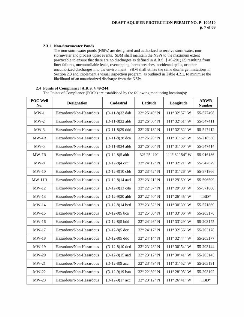
2.4 Points of Compliance [A.R.S. § 49-244]
The Points of Compliance (POCs) are established by the following monitoring location(s):
POC Well No. Designation Cadastral Latitude Longitude ADWR
Number
MW-1 Hazardous/Non-Hazardous (D-11-8)32 dab 32° 25' 40" N 111° 32' 57" W 55-577498
MW-2 Hazardous/Non-Hazardous (D-11-8)32 abb 32° 26' 00" N 111° 32' 51" W 55-547411
MW-3 Hazardous/Non-Hazardous (D-11-8)29 ddd 32° 26' 13" N 111° 32' 32" W 55-547412
MW-4R Hazardous/Non-Hazardous (D-11-8)28 dca 32° 26' 20" N 111° 31' 52" W 55-218550
MW-5 Hazardous/Non-Hazardous (D-11-8)34 abb 32° 26' 06" N 111° 31' 00" W 55-547414
MW-7R Hazardous/Non-Hazardous (D-12-8)5 abb 32° 25’ 10” 111° 32’ 54” W 55-916136
MW-8 Hazardous/Non-Hazardous (D-12-8)4 ccc 32° 24' 12" N 111° 32' 21" W 55-547679
MW-10 Hazardous/Non-Hazardous (D-12-8)10 cbb 32° 23' 42" N 111° 31' 26" W 55-571866
MW-11R Hazardous/Non-Hazardous (D-12-8)14 aad 32° 23' 21" N 111° 29' 59" W 55-596599
MW-12 Hazardous/Non-Hazardous (D-12-8)13 cda 32° 22' 37" N 111° 29' 00" W 55-571868
MW-13 Hazardous/Non-Hazardous (D-12-9)20 abb 32° 22' 40" N 111° 26' 45" W TBD*
MW-14 Hazardous/Non-Hazardous (D-12-8)14 bcd 32° 23' 52" N 111° 30' 39" W 55-571869
MW-15 Hazardous/Non-Hazardous (D-12-8)5 bca 32° 25' 00" N 111° 33' 06" W 55-203176
MW-16 Hazardous/Non-Hazardous (D-12-8)5 bdd 32° 24' 46" N 111° 33' 29" W 55-203175
MW-17 Hazardous/Non-Hazardous (D-12-8)5 dcc 32° 24' 17" N 111° 32' 56" W 55-203178
MW-18 Hazardous/Non-Hazardous (D-12-8)5 ddc 32° 24' 14" N 111° 32' 44" W 55-203177
MW-19 Hazardous/Non-Hazardous (D-12-8)10 dcd 32° 23' 23" N 111° 30' 54" W 55-203144
MW-20 Hazardous/Non-Hazardous (D-12-8)15 aad 32° 23' 12" N 111° 30' 41" W 55-203145
MW-21 Hazardous/Non-Hazardous (D-12-8)9 acc 32° 23' 49" N 111° 31' 52" W 55-203191
MW-22 Hazardous/Non-Hazardous (D-12-9)19 baa 32° 22' 39" N 111° 28' 05" W 55-203192
MW-23 Hazardous/Non-Hazardous (D-12-9)17 acc 32° 23' 12" N 111° 26' 41" W TBD*
DRAFT AQUIFER PROTECTION PERMIT NO. P- 100510 p. 8 of 69
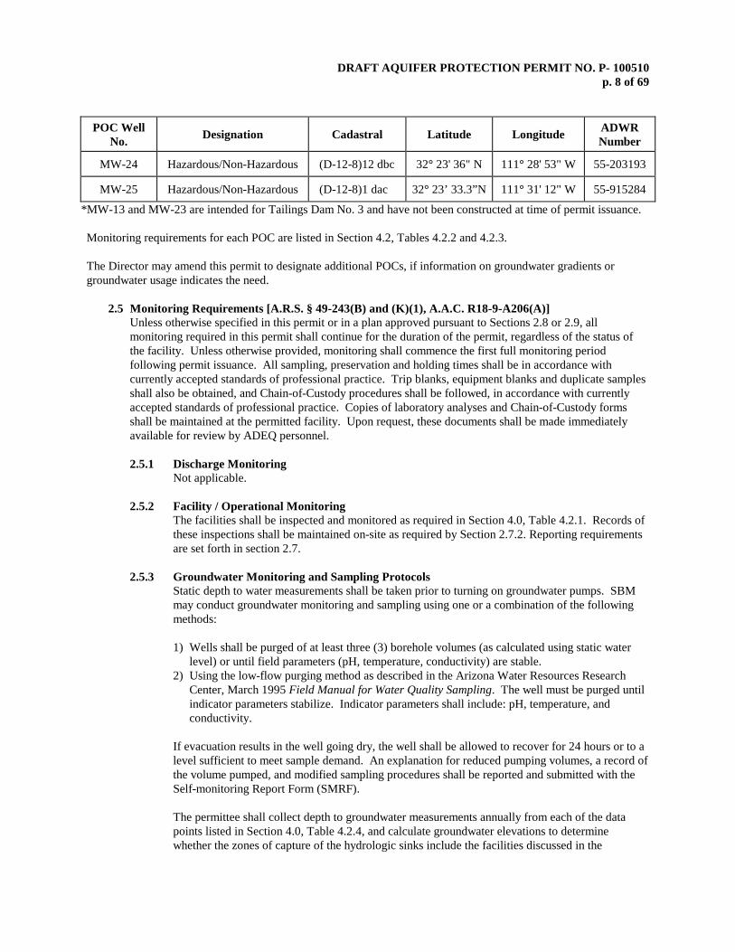
POC Well No. Designation Cadastral Latitude Longitude ADWR
Number
MW-24 Hazardous/Non-Hazardous (D-12-8)12 dbc 32° 23' 36" N 111° 28' 53" W 55-203193
MW-25 Hazardous/Non-Hazardous (D-12-8)1 dac 32° 23’ 33.3”N 111° 31' 12" W 55-915284
*MW-13 and MW-23 are intended for Tailings Dam No. 3 and have not been constructed at time of permit issuance.
Monitoring requirements for each POC are listed in Section 4.2, Tables 4.2.2 and 4.2.3. The Director may amend this permit to designate additional POCs, if information on groundwater gradients or groundwater usage indicates the need.
2.5 Monitoring Requirements [A.R.S. § 49-243(B) and (K)(1), A.A.C. R18-9-A206(A)] Unless otherwise specified in this permit or in a plan approved pursuant to Sections 2.8 or 2.9, all monitoring required in this permit shall continue for the duration of the permit, regardless of the status of the facility. Unless otherwise provided, monitoring shall commence the first full monitoring period following permit issuance. All sampling, preservation and holding times shall be in accordance with currently accepted standards of professional practice. Trip blanks, equipment blanks and duplicate samples shall also be obtained, and Chain-of-Custody procedures shall be followed, in accordance with currently accepted standards of professional practice. Copies of laboratory analyses and Chain-of-Custody forms shall be maintained at the permitted facility. Upon request, these documents shall be made immediately available for review by ADEQ personnel.
2.5.1 Discharge Monitoring
Not applicable.
2.5.2 Facility / Operational Monitoring The facilities shall be inspected and monitored as required in Section 4.0, Table 4.2.1. Records of these inspections shall be maintained on-site as required by Section 2.7.2. Reporting requirements are set forth in section 2.7.
2.5.3 Groundwater Monitoring and Sampling Protocols
Static depth to water measurements shall be taken prior to turning on groundwater pumps. SBM may conduct groundwater monitoring and sampling using one or a combination of the following methods: 1) Wells shall be purged of at least three (3) borehole volumes (as calculated using static water
level) or until field parameters (pH, temperature, conductivity) are stable. 2) Using the low-flow purging method as described in the Arizona Water Resources Research
Center, March 1995 Field Manual for Water Quality Sampling. The well must be purged until indicator parameters stabilize. Indicator parameters shall include: pH, temperature, and conductivity.
If evacuation results in the well going dry, the well shall be allowed to recover for 24 hours or to a level sufficient to meet sample demand. An explanation for reduced pumping volumes, a record of the volume pumped, and modified sampling procedures shall be reported and submitted with the Self-monitoring Report Form (SMRF). The permittee shall collect depth to groundwater measurements annually from each of the data points listed in Section 4.0, Table 4.2.4, and calculate groundwater elevations to determine whether the zones of capture of the hydrologic sinks include the facilities discussed in the
DRAFT AQUIFER PROTECTION PERMIT NO. P- 100510 p. 9 of 69
ASARCO letters and potentiometric map (S-903-06 G) dated August 14, 1992. The permittee shall use the most recent groundwater elevation data to draw the two approximately perpendicular cross-sections for each of the four (4) hydrologic sinks. Contiguous cross sections for more than one hydrologic sink may be used where appropriate. The cross-sections shall include a cumulative (historic) listing of groundwater elevations collected at each data point. The cross-sections shall be to scale, and shall indicate the ground surface, the potentiometric surface, the location of wells and other depth to groundwater monitoring points, and the approximate limits of mining and/or leaching operations within the scope of the cross-section.
If, during the annual monitoring period, one (or more) of the data point(s) listed on Table 4.2.4 cannot be measured due to physical constraints, e.g. plugging or shearing off, the permittee shall give the ADEQ Groundwater Section ninety (90) days notice of intent to use an alternative and equivalent depth-to-groundwater measurement data point.
2.5.3.1 Point of Compliance Well Replacement
In the event that one or more of the designated POC wells should become unusable or inaccessible due to damage, a replacement POC well shall be constructed and installed upon approval by ADEQ as specified in Section 2.5.6. If the replacement well is 50 feet or less from the original well, the ALs and/or aquifer quality limits (AQLs) calculated for the designated POC well shall apply to the replacement well.
2.5.3.2 Passive Containment Demonstration
Based on supporting documentation provided in the Applications, the permittee has satisfactorily predicted that the North Silver Bell, El Tiro, West Oxide and Oxide hydrologic sinks will create “passive containment capture zones,” as per A.R.S. § 49-243(G). Demonstration of passive containment shall be based solely on natural or engineered topographical, geological or hydrological control measures that can operate without continuous maintenance.
A post-audit of the approved groundwater flow model shall be conducted every five (5) years (see Compliance Schedule Item No. 8 and Section 2.7.5). Factors to be evaluated in the post-audit include groundwater inflow, the estimated ultimate pit lake level, the estimated time to reach static water level, and any potential for the water level in the hydrologic sink to rise to an elevation where the hydraulic gradient reverses and the hydrologic sink can no longer be maintained. The assumptions about mine development and infiltration shall be revised in terms of the actual changes in the hydrologic sink configuration, leaching areas, leach rates, sump locations, water balance, annual precipitation and storm events. The resulting compilation shall be compared to predictions provided by the groundwater flow model for the previous calibration period.
2.5.3.3 Alert Levels for POC Wells
Alert Levels (ALs) shall be calculated for all contaminants likely to be present in the discharge from the facility with an established numeric AWQS for each POC well. The ALs for the POC wells shall be established and calculated by the following formula or another valid statistical method submitted to the Groundwater Section in writing and approved for this permit:
AL = M + KS
Where M = mean, S = standard deviation, and K = one-sided normal tolerance interval with a 95% confidence level (Lieberman, G.J. (1958) Tables for One-sided Statistical Tolerance Limits: Industrial Quality Control, Vol. XIV, No. 10). Obvious outliers should

DRAFT AQUIFER PROTECTION PERMIT NO. P- 100510 p. 10 of 69
be excluded from the data used in the AL calculation. The following criteria shall be met in establishing ALs in the permit: 1. The AL shall be calculated for a parameter using the analyses from a minimum of
eight (8) consecutive quarterly sample rounds. 2. Any data where the PQL exceeds 80% of the AWQS shall not be included in the AL
calculation. 3. If a parameter is below the detection limit, the permittee must report the value as
“less than” the numeric value for the PQL or detection limit for the parameter, not just as “non-detect”. For those parameters, the permittee shall use a value of one-half the reported detection limit for the AL calculation.
4. If the analytical results from more than 50% of the samples for a specific parameter are non-detect, then the AL shall be set at 80% of the AWQS.
5. If the calculated AL for a specific constituent and well is less than 80% of the AWQS, the AL shall be set at 80% of the AWQS for that constituent in that well.
2.5.3.3.1 Trend Analysis for Sulfate (Wells MW-13 and MW-15 through MW 25) The permittee shall monitor for sulfate in well MW-13 (when installed), MWs-15 through
22, MW-23 (when installed), and MWs 24 and 25 as required in Section 3.0 and Table 4.2.3.
2.5.3.4 Aquifer Quality Limits for POC Wells For monitored analytes listed in Tables 4.2.2 and 4.2.3 for which a numeric AWQS has been established and where the AQL is shown as “reserved”, the AQL shall be established as follows after completion of the ambient monitoring consisting of at least eight (8) consecutive quarterly samples: 1. If the calculated AL is less than the AWQS, then the AQL shall be set equal to the
AWQS. 2. If the calculated AL is greater than the AWQS, then the AQL shall be set equal to the
calculated AL value, and no AL shall be set for that constituent at that monitoring point.
2.5.4 Surface Water Monitoring and Sampling Protocols
There is no surface water monitoring or sampling required as part of this permit. However, visual inspections are required as specified in Section 4.0, Table 4.2.1.
2.5.5 Analytical Methodology
All samples collected for compliance monitoring shall be analyzed using Arizona state-approved methods. If no state-approved method exists, then any appropriate EPA-approved method shall be used. Regardless of the method used, the detection limits must be sufficient to determine compliance with the regulatory limits of the parameters specified in this permit. If all methods have detection limits higher than the applicable limit, the permittee shall follow the contingency requirements of Section 2.6 and may propose “other actions” including amending the permit to set higher limits. Analyses shall be performed by a laboratory licensed by the Arizona Department of Health Services, Office of Laboratory Licensure and Certification unless exempted under A.R.S. § 36-495.02. For results to be considered valid, all analytical work shall meet quality control standards specified in the approved methods. A list of Arizona state-certified laboratories can be obtained at the address below:
Arizona Department of Health Services Office of Laboratory Licensure and Certification
DRAFT AQUIFER PROTECTION PERMIT NO. P- 100510 p. 11 of 69
250 North 17th Avenue Phoenix, Arizona 85007 Phone: (602) 364-0720
2.5.6 Installation and Maintenance of Monitoring Equipment; Replacement of Groundwater Wells
Monitoring equipment required by this permit shall be installed and maintained so that representative samples required by the permit can be collected. If new groundwater wells are determined to be necessary, the construction details shall be submitted to the ADEQ Groundwater Section for approval prior to installation and the permit shall be amended to include any new wells.
2.6 Contingency Plan Requirements
[A.R.S. § 49-243(K)(3), (K)(7) and A.A.C. R18-9-A204 and R18-9-A205]
2.6.1 General Contingency Plan Requirements At least one copy of this permit and the approved contingency and emergency response plan(s) submitted in the application shall be maintained at the location where day-to-day decisions regarding the operation of the facility are made. The permittee shall be aware of and follow the contingency and emergency response plans. The permittee is subject to enforcement action for the failure to comply with any contingency actions in this permit.
Any AL that is exceeded or any violation of an AQL, DL, or other permit condition shall be reported to ADEQ following the reporting requirements in Section 2.7.3, unless more specific reporting requirements are set forth in Section 2.6. The permittee is responsible for compliance with contingency plans relating to the exceedance of an AL or violation of a DL, AQL, or any other permit condition.
Some contingency actions involve verification sampling. Verification sampling shall consist of the first follow-up sample collected from a location that previously indicated a violation of an AQL, DL or other permit condition or the exceedance of an AL. Collection and analysis of the verification sample shall use the same protocols and test methods to analyze for the parameter(s) that exceeded an AL or violated an AQL, DL or other permit conditions. Where verification sampling is specified in this permit, it is the option of the permittee to perform such sampling. If verification sampling is not conducted within the timeframe allotted, ADEQ and the permittee shall presume the initial sampling result to be confirmed as if verification sampling has been conducted.
2.6.2 Exceeding of Alert Levels
1. Exceeding of AL #1 for Normal Liner Leakage
If AL #1 as specified in Section 2.0, Table 2.2 has been exceeded, the permittee shall take the following actions: a. Within five (5) days of discovery, determine if the fluid in the collection sump is
operational/process water from the pond by measuring the pH and conductivity of fluids in the pond and in the sump to allow direct comparison in water quality.
b. Within 5 days of discovery, notify the ADEQ Water Quality Groundwater Section, in accordance with Section 2.7.3.1 (Permit Violation and AL Status Reporting), and include in the notification an assessment of the type of water in the sump based on the measurements taken according to 1(a) listed above.
c. Within 15 days of discovery, assess the condition of the liner system using visual methods, electrical leak detection, or other methods as applicable.
d. Monitor fluid removal from the LCRS on a daily basis until the daily volume of fluid quantified either remains below AL #1 for 30 days, or the ADEQ completes a review of a Liner Leakage Assessment Report and determines that the permittee must perform repairs.
e. Within 30 days of discovery of exceeding AL #1, the permittee shall submit an initial
DRAFT AQUIFER PROTECTION PERMIT NO. P- 100510 p. 12 of 69
report to the ADEQ Water Quality Groundwater Section to address problems identified from the initial assessment of the liner system, the source of the fluid, and any remedial actions taken to minimize the future occurrences. The report shall include the results of the initial liner evaluation, methods used to locate the leak(s) if applicable, any repair procedures implemented to restore the liner to optimal operational status if required, and other information necessary to ensure the future occurrence of the incidence will be minimized.
f. For leakage rates that continue to exceed AL #1 and are below AL #2, a Liner Leakage Assessment Report shall be included in the next annual report described in Section 2.7.4 (Operational, Other or miscellaneous Reporting) of this permit. The permittee may also submit the Liner Leakage Assessment Report to the ADEQ prior to the annual report due date. This Liner Leakage Assessment Report shall be submitted to the ADEQ Groundwater Section. The ADEQ will review the Liner Leakage Assessment Report and may require that the permittee take additional action to address the problems identified from the assessment of the liner and perform other applicable repair procedures as directed by the ADEQ, including repair of the liner or addressing and controlling infiltration of non-operational water detected in the LCRS.
2. Exceeding of AL #2 for Liner Failure or Rips If an Alert Level #2 specified in Section 2.0, Table 2.2 has been exceeded, the permittee shall: a. Where possible, cease all discharge to the pond or redirect the discharge to another pond
which does not have an AL #2 violation. In ponds where discharge to the pond cannot immediately cease, lower pond solution level as much as possible, cease application of leach solutions to the associated leach dump and continue to pump solution from the leak detection sump. Within 24 hours, determine if water in the collection sump is operational/process water by measuring the pH and conductivity of fluids contained in the pond and in the sump to allow direct comparison in water quality.
b. Within five (5) days of discovery, notify the ADEQ Water Quality Groundwater Section, in accordance with Section 2.7.3.1 (Permit Violation and AL Status Reporting) and include an assessment regarding the type of water in the sump based upon the measurements taken according to 2(a) listed above.
c. Within five (5) days of discovery, collect samples from the liquid contained in the collection sump and analyze the samples in accordance with Table 4.2.3. Within 30 days of exceeding an AL #2, submit the analytical data to the ADEQ Water Quality Groundwater Section.
d. Within five (5) days of discovery or once discharge to the pond ceases (where discharge to the pond cannot immediately cease), lower pond solution level to a point where the location of the leak(s) can be identified using visual methods, electrical leak detection, or other methods as applicable.
e. Within 30 days of exceeding an AL #2, submit a report to the ADEQ as specified in Section 2.7.3.2 (Permit Violation and AL Status Reporting). Upon review of the report, the ADEQ may request additional monitoring or remedial actions.
f. Within 60 days of exceeding an AL #2, submit for approval to the ADEQ, a corrective action plan to address all problems identified from the assessment of the liner system. At the direction of the ADEQ, the permittee shall implement the approved plan.
g. Within 30 days of being directed to implement the corrective action plan by the ADEQ, repair any leaks identified in 2(d) above and perform all approved corrective actions.
h. Within 30 days of completion of corrective actions, submit to the ADEQ, a written report as specified in Section 2.6.6 (Corrective Actions).
2.6.2.1 Exceeding of Performance Levels Set for Operational Conditions
Performance Levels Set for Freeboard
DRAFT AQUIFER PROTECTION PERMIT NO. P- 100510 p. 13 of 69
In the event that freeboard performance levels specified in Section 4.0, Table 4.1 for a surface pond are not maintained, the permittee shall: 1. As soon as practicable, cease or reduce discharging to the pond to prevent
overtopping. Remove and properly dispose or recycle to other operations the excess fluid in the reservoir until the fluid level is restored at or below the permitted freeboard limit.
2. Within five (5) days of discovery, evaluate the cause of the incident and adjust operational conditions as necessary to avoid future occurrences.
3. Record in the facility log, the amount of fluid removed, a description of the removal method, and the disposal arrangements. The facility log shall be maintained according to Section 2.7.2 (Operational Inspection / Log Book Recordkeeping).
4. The facility is no longer on alert status once the operational indicator no longer indicates that the freeboard performance level is being exceeded. The permittee shall, however, complete all tasks necessary to return the facility to its pre-alert operating condition.
2.6.2.2 Exceeding of Alert Levels Set for Discharge Monitoring
Not applicable.
2.6.2.3 Exceeding of Alert Levels in Groundwater Monitoring
2.6.2.3.1 Alert Levels for Indicator Parameters
Not applicable.
2.6.2.3.2 Alert Levels for Pollutants with Numeric Aquifer Water Quality Standards
1. If an AL for a pollutant set in Table 4.2.2 or 4.2.3 has been exceeded,
the permittee shall request that the laboratory verify the sample results within five (5) days. If the verification analysis does not confirm an exceedance, the permittee may assume no exceedance and no further action is required under this subsection. If the verification analysis confirms an exceedance, the permittee may conduct verification sampling for that parameter within five (5) days of becoming aware of an AL exceedance. The permittee may use the results of another sample taken between the date of the last sampling event and the date of receiving the result as verification.
2a. If verification sampling confirms the AL exceedance or if the permittee opts not to perform verification sampling, then the permittee shall increase the frequency of monitoring for that parameter to monthly. In addition, the permittee shall immediately initiate an investigation of the cause of the AL exceedance, including inspection of all relevant discharging facilities and related pollution control devices, review of any operational and maintenance practices that might have resulted in an unexpected discharge, and hydrologic review of groundwater conditions including upgradient water quality from existing wells.
2b. If the verification sample does not confirm that an exceedance has occurred, the permittee shall notify ADEQ of the results and assume there has been no exceedance. No further action will then be required under this subsection.
3. The permittee shall initiate actions identified in the approved contingency plan referenced in Section 3.0 and specific contingency
DRAFT AQUIFER PROTECTION PERMIT NO. P- 100510 p. 14 of 69
measures identified in Section 2.6 to resolve any problems identified by the investigation which may have led to an AL exceedance. To implement any other corrective action the permittee shall obtain prior approval from ADEQ according to Section 2.6.6. Alternatively, the permittee may submit a technical demonstration, subject to written approval by the Groundwater Section, that although an AL is exceeded, pollutants are not reasonably expected to cause a violation of an AQL. The demonstration may propose a revised AL or monitoring frequency for approval in writing by the Groundwater Section.
4. Within 30 days after confirmation of an AL exceedance, the permittee shall submit the laboratory results to the Water Quality Groundwater Section along with a summary of the findings of the investigation, the cause of the AL exceedance, and actions taken to resolve the problem.
5. The increased monitoring required as a result of an AL exceedance may be reduced to the regular frequency, if the results of three (3) sequential sampling events demonstrate that no parameters exceed the AL.
6. If the increased monitoring required as a result of an AL exceedance continues for more than six (6) sequential sampling events, the permittee shall submit a second (2nd) report documenting an investigation of the continued AL exceedance within 30 days of the receipt of laboratory results of the sixth (6th) sampling event.
7. Upon review of any submitted report under 2.6.2.3.2, the Department may amend the permit to require additional monitoring, change the frequency of monitoring, or other actions.
2.6.2.3.3 Alert Levels to Protect Downgradient Users from Pollutants without
Numeric Aquifer Water Quality Standards Not applicable.

DRAFT AQUIFER PROTECTION PERMIT NO. P- 100510 p. 15 of 69
2.6.3 Discharge Limitations Violations
2.6.3.1 Liner Failure, Containment Structure Failure, or Unexpected Loss of Fluid for a Reason Other than Overtopping
In the event of liner failure, containment structure failure, or unexpected loss of fluid that does not trigger Sections 2.6.2(1) or 2.6.2(2) and that results in a discharge as defined by A.R.S. § 49-201(12) and as described in Section 2.3, the permittee shall take the following actions:
1. As soon as practicable, cease or minimize all discharges to the surface pond as
necessary to prevent any further releases to the environment. 2. Within 24-hours of discovery, notify ADEQ Water Quality Groundwater Section. 3. Within five (5) days of discovery of a failure that resulted in a discharge, collect
representative samples of the fluid remaining in the surface pond. Samples shall be analyzed for the parameters specified in Table 4.2.2. Within thirty (30) days of the incident, submit a copy of the analytical results to ADEQ Water Quality Groundwater Section.
4. Within fifteen (15) days of discovery, initiate an evaluation to determine the cause of the incident. Identify the circumstances that resulted in the failure and assess the condition of the surface pond and liner system. Following completion of the evaluation, implement corrective actions as necessary to resolve the problems identified in the evaluation. Initiate repairs to any failed liner, system, structure, or other component as needed to restore proper functioning of the surface pond. The permittee shall not resume discharging to the surface pond until repairs of any failed liner or structure are performed. Repair procedures, methods, and materials used to restore the system(s) to proper operating condition shall be described in the facility log/recordkeeping file and made available for ADEQ review.
5. As soon as practicable, remove fluid remaining in the surface pond as necessary to prevent further releases to the subsurface and/or to perform repairs. Record in the facility log/recordkeeping file the amount of fluid removed, a description of the removal method, and other disposal arrangements. The facility log/recordkeeping file shall be maintained according to Section 2.7.2 (Operation Inspection/Log Book/Recordkeeping File).
6. Within thirty (30) days of discovery of the incident, submit a report to ADEQ as specified in Section 2.7.3.2 (Permit Violation and Alert Level Status Reporting). Include a description of the actions performed in Subsections 1 through 5 listed above. Upon review of the report, ADEQ may request additional monitoring or remedial actions.
7. Within sixty (60) days of discovery, conduct an assessment of the impacts to the subsoil and/or groundwater resulting from the incident. If soil or groundwater is impacted such that it could cause or contribute to an exceedance of an AQL at the applicable point of compliance, submit to ADEQ, for approval, a corrective action plan to address such impacts, including identification of remedial actions and/or monitoring, and a schedule for completion of activities. At the direction of ADEQ, the permittee shall implement the approved plan.
8. Within thirty (30) days of completion of corrective actions, submit to ADEQ, a written report as specified in Section 2.6.6 (Corrective Actions). Upon review of the report, ADEQ may amend the permit to require additional monitoring, increased frequency of monitoring, amendments to permit conditions, or other actions.

DRAFT AQUIFER PROTECTION PERMIT NO. P- 100510 p. 16 of 69
2.6.3.2 Overtopping of a Surface Pond
If overtopping of fluid from a permitted surface pond occurs, and results in a discharge pursuant to A.R.S. § 49-201(12), the permittee shall:
1. As soon as practicable, cease or minimize discharges to the surface pond to prevent
any further releases to the environment. 2. Within 24 hours of discovery, notify ADEQ Water Quality Groundwater Section. 3. Within five (5) days, collect representative samples of the fluid contained in the
surface pond. Samples shall be analyzed for the parameters specified in Table 4.2.2. Within thirty (30) days of the incident, submit a copy of the analytical results to ADEQ Water Quality Groundwater Section.
4. As soon as practicable, remove and properly dispose of excess fluid in the pond until the fluid level is restored at or below the appropriate freeboard as described in Table 4.1.1. Record in the facility log, the amount of fluid removed, a description of the removal method, and the disposal arrangements. The facility log/recordkeeping file shall be maintained according to Section 2.7.2 (Operation Inspection/Log Book/Recordkeeping File).
5. Within thirty (30) days of discovery, evaluate the cause of the overtopping and identify the circumstances that resulted in the incident. Implement corrective actions as appropriate and adjust operational conditions as necessary to resolve the problems identified in the evaluation. Repair any systems as necessary to prevent future occurrences of overtopping.
6. Within thirty (30) days of discovery of overtopping, submit a report to ADEQ Groundwater Section as specified in Section 2.7.3.2 (Permit Violation and Alert Level Status Reporting). Include a description of the actions performed in Subsections 1 through 5 listed above. Upon review of the report, ADEQ may request additional monitoring or remedial actions.
7. Within sixty (60) days of discovery, and based on sampling in Subsection 3 above, conduct an assessment of the impacts to the subsoil and/or groundwater resulting from the incident.
8. If soil or groundwater is impacted such that it could cause or contribute to an exceedance of an AQL at the applicable point of compliance, submit to ADEQ for approval, a corrective action plan to address such impacts, including identification of remedial actions and/or monitoring, and a schedule for completion of activities. At the direction of ADEQ, the permittee shall implement the approved plan.
9. Within thirty (30) days of completion of corrective actions, submit to ADEQ, a written report as specified in Section 2.6.6 (Corrective Actions). Upon review of the report, ADEQ may amend the permit to require additional monitoring, increased frequency of monitoring, amendments to permit conditions, or other actions.
2.6.3.3 Inflows of Unexpected Materials to the West Oxide Pond (Facility no. 154)
If any unexpected materials flow to the West Oxide Pond (Facility no. 154), the permittee shall:
1. As soon as practicable, cease all unexpected inflows to the surface pond. 2. Within 24 hours of discovery, notify ADEQ Water Quality Groundwater Section. 3. Within five (5) days of the incident, identify the source of the material and determine
the cause for the inflow. Characterize the unexpected material and contents of the affected pond, and evaluate the volume and concentration of the material to determine if it is compatible with the surface pond liner system. Based on the evaluation of the incident, repair any systems or equipment and/or adjust operations, as necessary to prevent future occurrences of inflows of unexpected materials.
DRAFT AQUIFER PROTECTION PERMIT NO. P- 100510 p. 17 of 69
4. Within thirty (30) days of an inflow of unexpected materials, submit a report to ADEQ as specified in Section 2.7.3.2 (Permit Violation and Alert Level Status Reporting). Include a description of the actions performed in Subsections 1 through 3 listed above. Upon review of the report, ADEQ may request additional monitoring or remedial actions.
5. Upon review of the report, ADEQ may amend the permit to require additional monitoring, increased frequency of monitoring, amendments to permit conditions, or other actions.
2.6.4 Aquifer Quality Limit Violation
1. If an AQL set in Table 4.2.2 or 4.2.3 has been exceeded, the permittee shall request that the laboratory verify the sample results within five (5) days. If the analysis does not confirm that an exceedance has occurred, the permittee may assume that there is no exceedance and no further action is required under this subsection. If the exceedance is confirmed, the permittee may conduct verification sampling for the parameter within five (5) days of becoming aware of an AQL exceedance. The permittee may use the results of another sample taken between the date of the last sampling event and the date of receiving the result as verification.
2a. If verification sampling confirms that the AQL is violated for the parameter or if the permittee opts not to perform verification sampling, then the permittee shall increase the frequency of monitoring to monthly. In addition, the permittee shall immediately initiate an evaluation for the cause of the violation, including inspection of all relevant discharging units and related pollution control devices, and review of any operational and maintenance practices that might have resulted in unexpected discharge. The permittee also shall submit a report according to Section 2.7.3, which includes a summary of the findings of the investigation, the cause of the violation, and actions taken to resolve the problem. If the permittee demonstrates within 30 days that the exceedance was not caused or contributed to by pollutants discharged from the facility, monitoring for the parameter may be reduced to the regular frequency. If the permittee demonstrates within 30 days that the exceedance was caused or contributed to by pollutants discharged from the facility, the permittee shall consider and ADEQ may require corrective action that may include control of the source of discharge, cleanup of affected soil, surface water or groundwater, and mitigation of the impact of pollutants on existing uses of the aquifer. Corrective actions shall either be specifically identified in this permit, included in an ADEQ approved contingency plan, or separately approved according to Section 2.6.6.
2b. If the verification sample does not confirm that an exceedance has occurred, the permittee shall notify ADEQ of the results and assume there has been no exceedance. No further action will then be required under this subsection.
3. Upon review of the submitted report, the Department may amend the permit to require additional monitoring, change the frequency of monitoring, or other actions.
4. The permittee shall notify any downstream or down-gradient users who may be directly affected by the discharge.
5. The increased monitoring required as a result of an AQL exceedance may be reduced to the regular frequency, if the results of three (3) sequential sampling events demonstrate that no parameters exceed the AL.
2.6.5 Emergency Response and Contingency Requirements for Unauthorized Discharges pursuant
to A.R.S. §49-201(12) and pursuant to A.R.S. § 49-241 that Are Not Addressed Elsewhere in Section 2.6
2.6.5.1 Duty to Respond
The permittee shall act immediately to correct any condition resulting from a discharge pursuant to A.R.S. § 49-201(12) if that condition could pose an imminent and substantial endangerment to public health or the environment.

DRAFT AQUIFER PROTECTION PERMIT NO. P- 100510 p. 18 of 69
2.6.5.2 Discharge of Hazardous Substances or Toxic Pollutants
In the event of any unauthorized discharge pursuant to A.R.S. § 49-201(12) of suspected hazardous substances (A.R.S. § 49-201(19)) or toxic pollutants (A.R.S. § 49-243(I)) on the facility site, the permittee shall promptly isolate the area and attempt to identify the discharged material. The permittee shall record information, including name, nature of exposure and follow-up medical treatment, if necessary, on persons who may have been exposed during the incident. The permittee shall notify the ADEQ Water Quality Groundwater Section and the Southern Regional Office within 24 hours upon discovering the discharge of hazardous material which (a) has the potential to cause an AWQS or AQL to be exceeded at a POC, or (b) could pose an endangerment to public health or the environment.
2.6.5.3 Discharge of Non-hazardous Materials
In the event of any unauthorized discharge pursuant to A.R.S. § 49-201(12) of non-hazardous materials from the facility, the permittee shall promptly attempt to cease the discharge and isolate the discharged material. Discharged material shall be removed and the site cleaned up as soon as possible. The permittee shall notify the ADEQ Water Quality Groundwater Section and the Southern Regional Office within 24 hours upon discovering the discharge of non-hazardous material which (a) has the potential to cause an AQL to be exceeded, or (b) could pose an endangerment to public health or the environment.
2.6.5.4 Reporting Requirements
The permittee shall submit a written report for any unauthorized discharges reported under Sections 2.6.5.2 and 2.6.5.3 to ADEQ Southern Regional Office and the ADEQ Water Quality Groundwater Section within thirty (30) calendar days of the discharge or as required by subsequent ADEQ action. The report shall summarize the event, including any human exposure, and facility response activities and include all information specified in Section 2.7.3. Additionally, the report shall provide the following information: 1. A description of the leak or unauthorized discharge and its cause; 2. The period of leak or unauthorized discharge, including the exact date and time, if
known, and the anticipated time period the leak or discharge is expected to continue, if not stopped;
3. Any action taken or planned to mitigate the effects of the unauthorized discharge or leaks or to eliminate or prevent recurrence of the unauthorized discharge or leaks;
4. Any monitoring activity or other information that indicates that a pollutant is expected to cause a violation of an Aquifer Water Quality Standard; and
5. Any malfunction or failure of a pollution control device or other equipment process.
If a notice is issued by ADEQ subsequent to the discharge notification, any additional information requested in the notice shall also be submitted within the time frame specified in that notice. Upon review of the submitted report, ADEQ may require additional monitoring or corrective actions.
2.6.6 Corrective Actions Specific contingency measures identified in Section 2.6 have already been approved by ADEQ and do not require written approval to implement.
With the exception of emergency response actions taken under Section 2.6.5, the permittee shall obtain written approval from the Groundwater Section prior to implementing a corrective action to
DRAFT AQUIFER PROTECTION PERMIT NO. P- 100510 p. 19 of 69
accomplish any of the following goals in response to exceeding an AL or violation of an AQL, DL, or other permit condition: 1. Control of the source of an unauthorized discharge; 2. Soil cleanup; 3. Cleanup of affected surface waters; 4. Cleanup of affected parts of the aquifer; and 5. Mitigation to limit the impact of pollutants on existing uses of the aquifer.
Within thirty (30) days of completion of any corrective action, the operator shall submit to the ADEQ Water Quality Groundwater Section, a written report describing the causes, impacts, and actions taken to resolve the problem.
2.6.7 Slope Failures
If a slope failure involving the leach dumps, surface ponds, tailings ponds (dams), or liners occurs, the permittee shall promptly close the active area in the vicinity of the failure and conduct a field investigation of the failure’s origin and extent, its impact on the facility operations, temporary and permanent repairs, and changes in operational plans considered necessary.
2.7 Reporting and Recordkeeping Requirements
[A.R.S. § 49-243(K)(2) and A.A.C. R18-9-A206(B) and R18-9-A207]
2.7.1 Self-monitoring Report Form (SMRF)
1. The permittee shall complete the Self-monitoring Report Form (SMRF) in a format provided by ADEQ, and submit the completed report to the Water Quality Groundwater Section.
2. The permittee shall complete the SMRF to the extent that the information reported may be entered on the form. If no information is required during a reporting period, the permittee shall enter “not required” on the SMRF and submit the report to ADEQ.
3. The tables contained in Section 4.0 list the monitoring parameters and the frequencies for reporting results on the SMRF:
• Table 4.2.2 - Quarterly Compliance Groundwater Monitoring • Table 4.2.3 - Biennial Compliance Groundwater Monitoring
4. In addition to the SMRF, the information contained in A.A.C. R18-9-A206(B)(1) shall be
included for exceeding an AL or violation of an AQL, DL, or any other permit condition being reported in the current reporting period.
2.7.2 Operation Inspection / Log Book Recordkeeping
A signed copy of this permit shall be maintained at all times at the location where day-to-day decisions regarding the operation of the facility are made. A log book (paper copies, forms or electronic data) of the inspections and measurements required by this permit shall be maintained at the location where day-to-day decisions are made regarding the operation of the facility. The log book shall be retained for ten (10) years from the date of each inspection, and upon request, the permit and the log book shall be made immediately available for review by ADEQ personnel. The information in the log book shall include, but not be limited to, the following information as applicable: 1. Name of inspector; 2. Date and shift (or time) inspection was conducted; 3. Condition of applicable facility components;

DRAFT AQUIFER PROTECTION PERMIT NO. P- 100510 p. 20 of 69
4. Any damage or malfunction, and the date and time any repairs were performed; 5. Any observations or evidence of unauthorized discharge; 6. The date and time of any sampling; 7. Any other information required by this permit to be entered in the log book; and 8. Monitoring records for each measurement shall include:
a. The date, time, and exact place of the measurement and the name of each individual who performed the measurement;
b. The procedures used to make the measurement; and c. Any field notes relating to the information described in subsections 2.7.2.8(a) and (b) above.
2.7.3 Permit Violation and Alert Level Status Reporting
1. The permittee shall notify the Water Quality Groundwater Section in writing within five (5) days (except as provided in Section 2.6.5) of becoming aware of a violation of any permit condition, discharge limitation or of an AL exceedance for which notification requirements are not specified elsewhere in this permit. This notification shall include the results of the inspection documenting the permit violation, the inspection record, and whether the approved Contingency Plan was implemented.
2. The permittee shall submit a written report to the Water Quality Groundwater Section within thirty (30) days of becoming aware of the violation of any permit condition or discharge limitation. The report shall document all of the following: a. Identification and description of the permit condition for which there has been a violation
and a description of its cause; b. The period of violation including exact date(s) and time(s), if known, and the anticipated
time period during which the violation is expected to continue; c. Any corrective action taken or planned to mitigate the effects of the violation, or to
eliminate or prevent a recurrence of the violation; d. Any monitoring activity or other information which indicates that any pollutants would be
reasonably expected to cause a violation of an AWQS; e. Proposed changes to the monitoring which include changes in constituents or increased
frequency of monitoring; and f. Description of any malfunction or failure of pollution control devices or other equipment
or processes.
2.7.4 Biennial Groundwater, Operational, Other, or Miscellaneous Reporting The permittee shall, upon completion of the biennial sampling described in Table 4.2.3, submit a monitoring summary report to the Groundwater Section. This report shall be due at the same time as the SMRF submittal for the biennial sampling event. The report shall include, but not be limited to the following:
1. A description of any deviations from standard sampling protocols during the reporting period. 2. A summary of all exceedances of ALs and AQLs that occurred during the reporting period. 3 Graphical time versus concentration plots of field pH, sulfate, total dissolved solids, and any
parameter which exceeded an applicable AL or AQL in the past eight (8) quarters at each POC well, and tabulated sampling data for all wells required to be sampled by this permit during the last eight (8) quarters.
4. An updated table of all monitor wells in or within ¼-mile of the Pollutant Management Area including, but not limited to, location of well, depth of well, depth to water, and water level elevation.
5. A summary of any groundwater monitor wells replaced in the reporting period including, but not limited to, location of well, depth of well, depth to water, water level elevation, and screened interval.

DRAFT AQUIFER PROTECTION PERMIT NO. P- 100510 p. 21 of 69
2.7.5 Passive Containment Capture Zone Demonstration Reporting
A report summarizing the original passive containment demonstration and the revisions made to the model shall be submitted to the ADEQ Groundwater Section for review. The report shall include a table listing the groundwater elevations for the data points used to demonstrate the configuration of the hydraulic containment, flow vector analysis (including plan and cross-sectional figures at inflection points), and a potentiometric contour map based on groundwater elevations used in the post-audit demonstration. ADEQ will determine whether a full model recalibration is required. If a recalibration is necessary, a report describing the model output and the revisions and/or changes to the model shall be submitted to the ADEQ Groundwater Section. The permittee shall compare the current groundwater data to the previous model predictions and a report on the comparison shall be submitted to the ADEQ Groundwater Section for review.
2.7.6 Trend Analysis for Sulfate (Wells MW-13 and MW-15 through MW 25) Reporting 1. The permittee shall monitor for sulfate in well MW-13 (when installed), MWs-15 through 22,
MW-23 (when installed), and MWs 24 and 25 as required in Section 3.0 and Tables 4.2.3 and 4.2.4. The permittee shall submit a report to the ADEQ Groundwater Section by April 1st every other year beginning April 1, 2013 which includes a time versus concentration plot for sulfate analyzing data collected in each well since the fourth quarter of 2004. In addition to this plot, the permittee shall submit a report interpreting the data, including identification of any short-term and long-term trends and an extrapolation of future trends. To the extent there appear to be statistically significant increases in sulfate concentrations over time in a well or wells, the permittee also shall include an analysis of potential causes of these increases, including an assessment of whether and to what extent they may be attributable to facility operations and an assessment of BADCT effectiveness. The report shall also include site map(s) showing the location of monitor wells sampled for the report.
2. For MW-13 and MW-23, the permittee shall submit the initial time versus concentration plot
and analysis required above after the wells are installed, and eight quarterly samples are collected.
2.7.7 Reporting Location
All SMRFs shall be submitted to: Arizona Department of Environmental Quality Water Quality Groundwater Section Mail Code: 5415B-1 1110 W. Washington Street Phoenix, Arizona 85007 Phone (602) 771-4571
Or
Through the myDEQ portal accessible on the ADEQ website at: http://www.azdeq.gov/welcome-mydeq
All documents required by this permit to be submitted to the Water Quality Groundwater Section shall be directed to both of the following addresses:
Arizona Department of Environmental Quality Water Quality Groundwater Section

DRAFT AQUIFER PROTECTION PERMIT NO. P- 100510 p. 22 of 69
Mail Code: 5415B-3 1110 W. Washington Street Phoenix, Arizona 85007 Phone (602) 771-4999
2.7.8 Reporting Deadline The following table lists the quarterly report due dates:
Monitoring conducted during quarter: Quarterly Report due by:
January-March April 30 April-June July 30
July-September October 30 October-December January 30

DRAFT AQUIFER PROTECTION PERMIT NO. P- 100510 p. 23 of 69
The following table lists the semi-annual, annual and biennial report due dates (if applicable):
Monitoring conducted: Report due by:
Semi-annual: January-June July 30
Semi-annual: July-December January 30
Annual and Biennial: January-December January 30
2.7.9 Changes to Facility Information in Section 1.0 The Groundwater Section shall be notified within ten (10) days of any change of facility information including Facility Name, Permittee Name, Mailing or Street Address, Facility Contact Person or Emergency Telephone Number.
2.8 Temporary Cessation [A.R.S. § 49-243(K)(8) and A.A.C. R18-9-A209(A)]
The permittee shall give written notice to the Water Quality Groundwater Section before ceasing operation of the facility for a period of sixty (60) days or greater. The permittee shall take the following measures upon temporary cessation:
At the time of notification the permittee shall submit for ADEQ approval a plan for maintenance of discharge control systems and for monitoring during the period of temporary cessation. Submittal of Self-Monitoring Report Forms (SMRFs) is still required; report “temporary cessation” in the comment section Immediately following ADEQ’s approval, the permittee shall implement the approved plan. If necessary, ADEQ shall amend permit conditions to incorporate conditions to address temporary cessation. During the period of temporary cessation, the permittee shall provide written notice to the Water Quality Groundwater Section of the operational status of the facility every three years. If the permittee intends to permanently cease operation of any facility, the permittee shall submit closure notification, as set forth in Section 2.9 below.
2.9 Closure [A.R.S. §§ 49-243(K)(6), 49-252 and A.A.C. R18-9-A209(B)]
For a facility addressed under this permit, the permittee shall give written notice of closure to the Water Quality Groundwater Section of the permittee’s intent to cease operation without resuming activity for which the facility was designed or operated. Submittal of Self-Monitoring Report Forms (SMRFs) is still required; report “temporary cessation” in the comment section 2.9.1 Closure Plan
Within 90 days following notification of closure, the permittee shall submit for approval to the Groundwater Section, a closure plan which meets the requirements of A.R.S. § 49-252 and A.A.C. R18-9-A209(B)(3). If the closure plan achieves clean closure immediately, ADEQ shall issue a letter of approval to the permittee. If the closure plan contains a schedule for bringing the facility to a clean closure configuration at a future date, ADEQ may incorporate any part of the schedule as an amendment to this permit.
2.9.2 Closure Completion
Upon completion of closure activities, the permittee shall give written notice to the Groundwater Section indicating that the approved closure plan has been implemented fully and providing supporting documentation to demonstrate that clean closure has been achieved (soil sample results, verification sampling results, groundwater data, as applicable). If clean closure has been achieved, ADEQ shall issue a letter of approval to the permittee at that time. If any of the following conditions apply, the permittee shall follow the terms of post-closure stated in this permit: 1. Clean closure cannot be achieved at the time of closure notification or within one (1) year
DRAFT AQUIFER PROTECTION PERMIT NO. P- 100510 p. 24 of 69
thereafter under a diligent schedule of closure actions. 2. Further action is necessary to keep the facility in compliance with AWQS at the applicable POC. 3. Continued action is required to verify that the closure design has eliminated discharge to the
extent intended. 4. Remediation or mitigation measures are necessary to achieve compliance with Title 49, Ch. 2. 5. Further action is necessary to meet property use restrictions. 6. SMRF submittals are still required until Clean Closure is issued.
2.10 Post-closure [A.R.S. §§ 49-243(K)(6), 49-252 and A.A.C. R18-9-A209(C)] Post-closure requirements shall be established based on a review of facility closure actions and will be subject to review and approval by the Groundwater Section.
In the event clean closure cannot be achieved pursuant to A.R.S. § 49-252, the permittee shall submit for approval to the Groundwater Section a post-closure plan that addresses post-closure maintenance and monitoring actions at the facility. The post-closure plan shall meet all requirements of A.R.S. §§ 49-201(30) and 49-252 and A.A.C. R18-9-A209(C). Upon approval of the post-closure plan, this permit shall be amended or a new permit shall be issued to incorporate all post-closure controls and monitoring activities of the post-closure plan. 2.10.1 Post-closure Plan
Reserved.
2.10.2 Post-closure Completion Reserved.
DRAFT AQUIFER PROTECTION PERMIT NO. P- 100510 p. 25 of 69
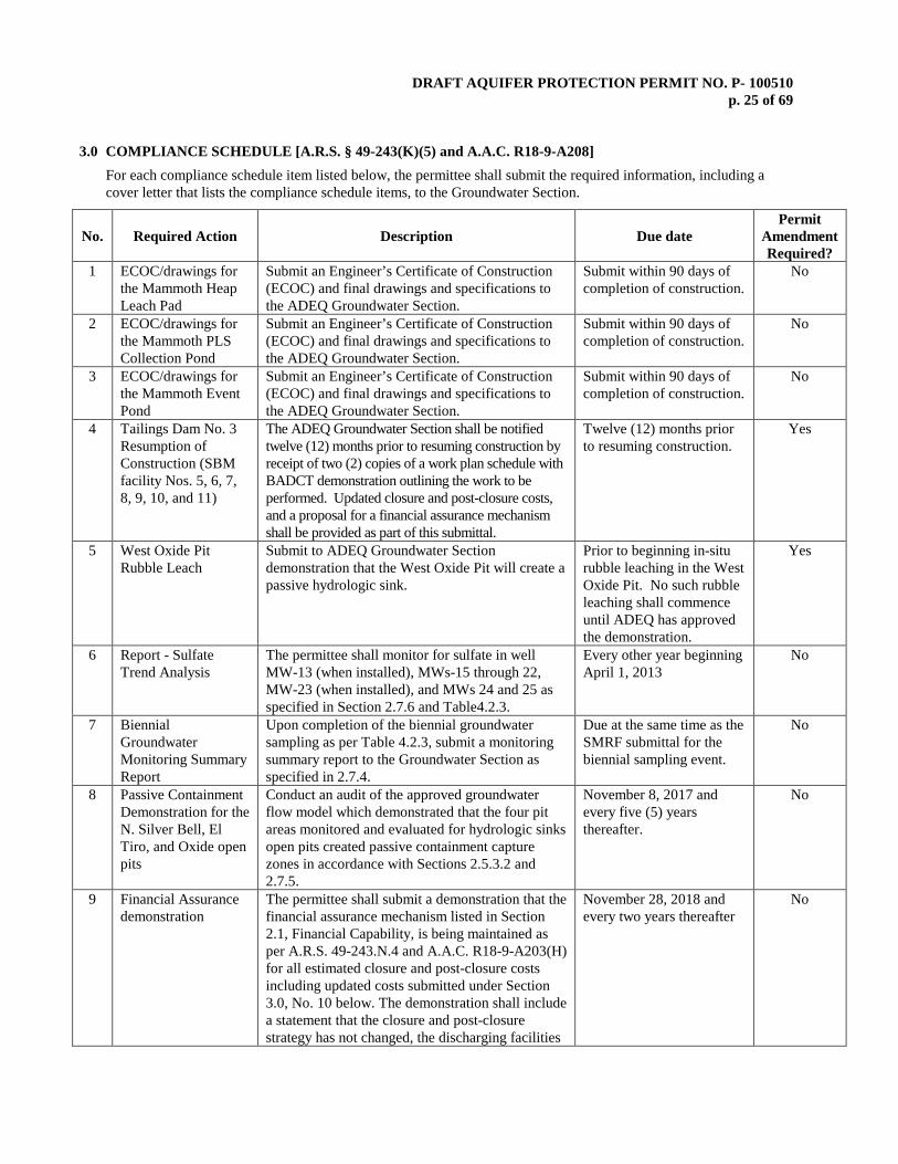
3.0 COMPLIANCE SCHEDULE [A.R.S. § 49-243(K)(5) and A.A.C. R18-9-A208]
For each compliance schedule item listed below, the permittee shall submit the required information, including a cover letter that lists the compliance schedule items, to the Groundwater Section.
No. Required Action Description Due date Permit
Amendment Required?
1 ECOC/drawings for the Mammoth Heap Leach Pad
Submit an Engineer’s Certificate of Construction (ECOC) and final drawings and specifications to the ADEQ Groundwater Section.
Submit within 90 days of completion of construction.
No
2 ECOC/drawings for the Mammoth PLS Collection Pond
Submit an Engineer’s Certificate of Construction (ECOC) and final drawings and specifications to the ADEQ Groundwater Section.
Submit within 90 days of completion of construction.
No
3 ECOC/drawings for the Mammoth Event Pond
Submit an Engineer’s Certificate of Construction (ECOC) and final drawings and specifications to the ADEQ Groundwater Section.
Submit within 90 days of completion of construction.
No
4 Tailings Dam No. 3 Resumption of Construction (SBM facility Nos. 5, 6, 7, 8, 9, 10, and 11)
The ADEQ Groundwater Section shall be notified twelve (12) months prior to resuming construction by receipt of two (2) copies of a work plan schedule with BADCT demonstration outlining the work to be performed. Updated closure and post-closure costs, and a proposal for a financial assurance mechanism shall be provided as part of this submittal.
Twelve (12) months prior to resuming construction.
Yes
5 West Oxide Pit Rubble Leach
Submit to ADEQ Groundwater Section demonstration that the West Oxide Pit will create a passive hydrologic sink.
Prior to beginning in-situ rubble leaching in the West Oxide Pit. No such rubble leaching shall commence until ADEQ has approved the demonstration.
Yes
6 Report - Sulfate Trend Analysis
The permittee shall monitor for sulfate in well MW-13 (when installed), MWs-15 through 22, MW-23 (when installed), and MWs 24 and 25 as specified in Section 2.7.6 and Table4.2.3.
Every other year beginning April 1, 2013
No
7 Biennial Groundwater Monitoring Summary Report
Upon completion of the biennial groundwater sampling as per Table 4.2.3, submit a monitoring summary report to the Groundwater Section as specified in 2.7.4.
Due at the same time as the SMRF submittal for the biennial sampling event.
No
8 Passive Containment Demonstration for the N. Silver Bell, El Tiro, and Oxide open pits
Conduct an audit of the approved groundwater flow model which demonstrated that the four pit areas monitored and evaluated for hydrologic sinks open pits created passive containment capture zones in accordance with Sections 2.5.3.2 and 2.7.5.
November 8, 2017 and every five (5) years thereafter.
No
9 Financial Assurance demonstration
The permittee shall submit a demonstration that the financial assurance mechanism listed in Section 2.1, Financial Capability, is being maintained as per A.R.S. 49-243.N.4 and A.A.C. R18-9-A203(H) for all estimated closure and post-closure costs including updated costs submitted under Section 3.0, No. 10 below. The demonstration shall include a statement that the closure and post-closure strategy has not changed, the discharging facilities
November 28, 2018 and every two years thereafter
No
DRAFT AQUIFER PROTECTION PERMIT NO. P- 100510 p. 26 of 69
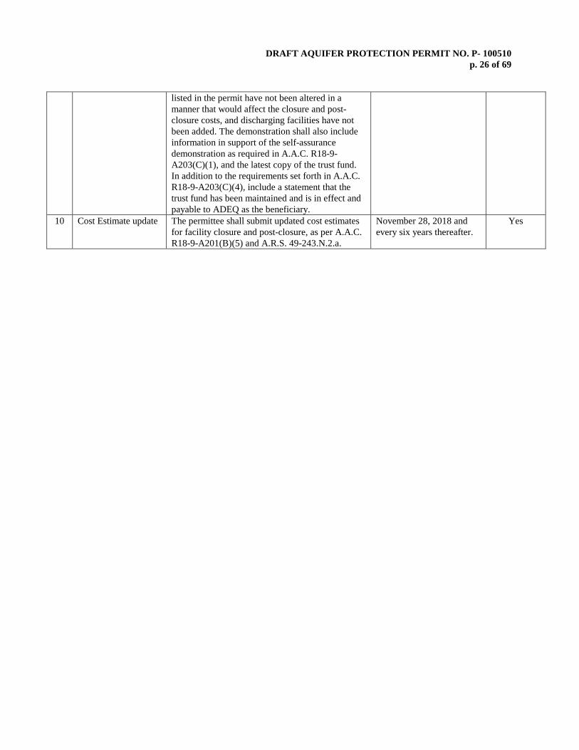
listed in the permit have not been altered in a manner that would affect the closure and post-closure costs, and discharging facilities have not been added. The demonstration shall also include information in support of the self-assurance demonstration as required in A.A.C. R18-9-A203(C)(1), and the latest copy of the trust fund. In addition to the requirements set forth in A.A.C. R18-9-A203(C)(4), include a statement that the trust fund has been maintained and is in effect and payable to ADEQ as the beneficiary.
10 Cost Estimate update The permittee shall submit updated cost estimates for facility closure and post-closure, as per A.A.C. R18-9-A201(B)(5) and A.R.S. 49-243.N.2.a.
November 28, 2018 and every six years thereafter.
Yes
DRAFT AQUIFER PROTECTION PERMIT NO. P- 100510 p. 27 of 69
4.0 TABLES OF FACILITY INFORMATION AND MONITORING REQUIREMENTS
4.1 PERMITTED FACILITIES AND BADCT
4.2 COMPLIANCE (or OPERATIONAL) MONITORING
TABLE 4.2.1 - Required Inspections and Operational Monitoring TABLE 4.2.2 - Quarterly Compliance Groundwater Monitoring TABLE 4.2.3 - Biennial Compliance Groundwater Monitoring
TABLE 4.2.4 - Groundwater Level Monitoring

DRAFT AQUIFER PROTECTION PERMIT NO. P- 100510 p. 28 of 69
TABLE 4.1 PERMITTED FACILITIES AND BADCT
Facility No. Facility Name Lat/Long Facility BADCTA,B,C
Non-Stormwater Ponds
120 El Tiro Area Drainage No. 9, 'A' Stream Stormwater Pond
32° 24' 17" N 111° 32' 46" W
Facility is a partially lined pond replacing facilities 117, 118, and 119 which have been removed. This facility receives flow from the upgradient watershed of the ET No. 9 Leach Dump. It is capable of containing a 100-year/24-hour storm event. The dam is a partially lined pond with a 60 mil HDPE liner, keyed into bedrock covering the up-stream face of a compacted earthen dam equipped with a spillway. The pond contains a small sump with a dedicated 500-gpm pump. Impounded water shall be pumped to either the El Tiro Pit or the ET II PLS Pond.
126 El Tiro Area Drainage No. 12, 'B' Stream Stormwater Pond
32° 24' 45" N 111° 33' 04" W
Facility is an unlined pond catching run-off from the western slopes of ET No. 6 Leach Dump (53), which has not been leached. Capable of containing run-off from a 100-year/24 hour storm event, it is equipped with a dedicated 500-gpm pump. Impounded non-stormwater shall be pumped to either the El Tiro Pit or to the ET I PLS Pond (41).
131 El Tiro Area Drainage No. 13, 'C' Stream Stormwater Pond
32° 24' 55" N 111° 33' 02" W
Facility is a partially lined pond. It takes flow from the upgradient watershed of the ET No. 1 and 6 Leach Dumps. Capable of containing a 100-year/24-hour storm event. The dam is a partially lined pond with a 60 mil HDPE liner, keyed into bedrock, covering the up-stream face of a compacted earthen dam equipped with a spillway. The pond contains a small sump with a dedicated 500-gpm pump. Impounded water shall be pumped to either the El Tiro Pit or the ET I PLS Pond.
17 Mill Stormwater Pond 32° 23' 24" N 111° 29' 44" W
Facility is an upgrade of a pre-existing pond collecting non-stormwater from the Mill Site area watershed. This up-grade is a partially lined pond with a 60 mil HDPE liner, keyed into bedrock, covering the up-stream face of a compacted earthen dam equipped with a spillway. A 2-foot compacted clay layer covers the keyed portion of the liner. The pond bottom will eventually be covered with a layer of slime settlement from impounded water. A sump is equipped with a dedicated 500 gpm pump, and the pond is capable of containing a 100-year/24-hour storm event. Impounded water shall be pumped to either the Oxide Pit or the Main Raffinate Pond (69).
152 New Barren Pond (near old Precip. Plant)
32° 23' 28" N 111° 30' 45" W
Facility 152 replaces facilities 35 and 36. Facility 152 is a lined pond with an underlying French drain running into a sump where facility 36 was located. This facility collects stormwater runoff from facilities 19 and 21. A quarterly water quality monitoring program at respective POC wells will verify the effectiveness of BADCT for facility 152.

DRAFT AQUIFER PROTECTION PERMIT NO. P- 100510 p. 29 of 69
26 Oxide III East Pregnant Leach Solution Pond
(no longer receives PLS)
32° 23' 42" N 111° 29' 14" W
Originally, Facility 26 received PLS from Oxide III leach dump (23). It is an unlined pond behind an earthen dam (17.8 feet high) keyed into bedrock at the bottom and at abutments. The average value of hydraulic conductivity from packer tests of the local bedrock is 1.6 x10⁻⁶ cm/sec. The pond bottom is covered with a layer of silty/clayey sediments. No longer receiving PLS, this facility has been converted into a non-stormwater pond. With 1.5 feet of freeboard, the 10-year/24-hour storm event is contained. Portable pumps and electric generators provide backup in case of a power failure.
29 Oxide V Pregnant Leach Solution Pond
(no longer receives PLS)
32° 23' 07" N 111° 30' 15" W
Facility has been modified to contain a 100-year/24-hour storm event in a lined pond catching run-off from the west, south, and east sides of Oxide V Leach Dump (28). No longer receiving PLS, this facility has been converted into a non-stormwater pond. A concrete dam (8 feet high) is keyed into bedrock at the bottom and at abutments. The average value of hydraulic conductivity from packer tests of the local bedrock is 5.7 x10⁻⁵ cm/sec. Portable pumps and electric generators provide backup in case of a power failure.
30 Oxide V Pregnant Leach
Solution Diversion Dam
(no longer receives PLS)
32° 23' 08" N 111° 30' 20" W
Facility has been modified to contain a 100-year/24-hour storm event. Originally, Facility 30 received PLS from Oxide V Leach dump (28). It is a partially lined pond. The average value of hydraulic conductivity from packer tests of the local bedrock is 5.7 x10⁻⁵ cm/sec. The pond bottom is covered with a layer of silty/clayey sediments. No longer receiving PLS, this facility has been converted into a non-stormwater pond. In addition, an intercept trench drain was installed to collect seepage. Portable pumps and electric generators provide backup in case of a power failure.
31 Oxide V Emergency Overflow
Dam (no longer receives PLS)
32° 23' 06" N 111° 30' 15" W
In 1998, Facility 31 was over excavated and HDPE-lined to contain the 100-year, 24 hour storm event with the liner tied to the existing concrete dam. It received overflow from facility 30, but is no longer receiving PLS. The average value of hydraulic conductivity from packer tests of the local bedrock is 5.7 x10⁻⁵ cm/sec. The pond bottom is covered with a layer of silty/clayey sediments. Portable pumps and electric generators provide backup in case of a power failure.
50 ET III Pregnant Leach Solution Pond
(no longer receives PLS)
32° 24' 24" N 111° 32' 28" W
Facility is no longer receiving PLS from ET III leach dump (49) and has been converted into a non-stormwater pond. Captured runoff is pumped to the C-stream Non-stormwater Pond (131). It is an unlined pond behind an earthen embankment (11.3 feet high) keyed into bedrock at the bottom and at abutments. The average value of hydraulic conductivity from packer tests of the local bedrock is 1.0 x10⁻⁵ cm/sec. The pond bottom is covered with a layer of silty/clayey sediments. Portable pumps and electric generators provide backup in case of a power failure.
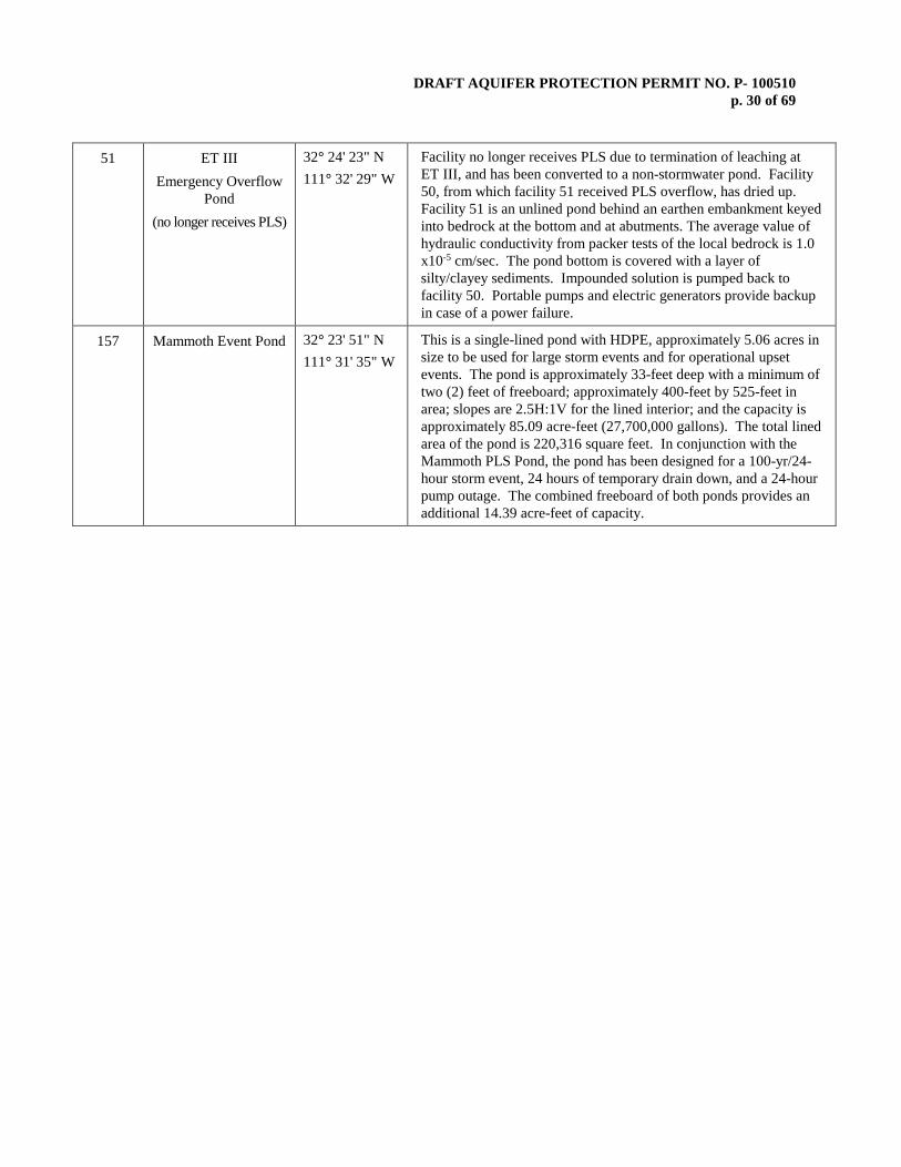
DRAFT AQUIFER PROTECTION PERMIT NO. P- 100510 p. 30 of 69
51 ET III Emergency Overflow
Pond (no longer receives PLS)
32° 24' 23" N 111° 32' 29" W
Facility no longer receives PLS due to termination of leaching at ET III, and has been converted to a non-stormwater pond. Facility 50, from which facility 51 received PLS overflow, has dried up. Facility 51 is an unlined pond behind an earthen embankment keyed into bedrock at the bottom and at abutments. The average value of hydraulic conductivity from packer tests of the local bedrock is 1.0 x10⁻⁵ cm/sec. The pond bottom is covered with a layer of silty/clayey sediments. Impounded solution is pumped back to facility 50. Portable pumps and electric generators provide backup in case of a power failure.
157 Mammoth Event Pond 32° 23' 51" N 111° 31' 35" W
This is a single-lined pond with HDPE, approximately 5.06 acres in size to be used for large storm events and for operational upset events. The pond is approximately 33-feet deep with a minimum of two (2) feet of freeboard; approximately 400-feet by 525-feet in area; slopes are 2.5H:1V for the lined interior; and the capacity is approximately 85.09 acre-feet (27,700,000 gallons). The total lined area of the pond is 220,316 square feet. In conjunction with the Mammoth PLS Pond, the pond has been designed for a 100-yr/24-hour storm event, 24 hours of temporary drain down, and a 24-hour pump outage. The combined freeboard of both ponds provides an additional 14.39 acre-feet of capacity.

DRAFT AQUIFER PROTECTION PERMIT NO. P- 100510 p. 31 of 69
Surface Ponds
154 West Oxide Pond 32° 23' 45" N 111° 31' 24" W
Facility was constructed at the southwest toe of the West Oxide Overburden Dump, to receive stormwater and runoff from the dump. The surface pond has been designed to contain a maximum of 6.01 acre-feet (9-feet deep) capable of containing a 100-year 24-hour storm event with 2-feet of freeboard. The pond has a liner system consisting of (from bottom to top): a prepared subgrade compacted to a minimum 95-percent of maximum dry density as determined by ASTM D-698; a sodium bentonite geosynthetic clay liner (GCL) with a maximum permeability of 5.0 x 10⁻⁹cm/s; a minimum of one (1) foot of protective soil; and a minimum of six (6) inches of marker gravel on the bottom of the pond. The pond has an access/maintenance ramp which is located at the southeastern corner of the surface pond. Runoff from the southwest face of the dump is directed into the pond by two (2) main channels located at the toe of the dump. The channels are constructed (from bottom to top) with a compacted fill subgrade, and rock riprap.
Process Solution Ponds 24 Oxide III Pregnant
Leach Solution Pond
32° 23' 32" N 111° 29' 25" W
Facility receives PLS from Oxide III leach dump (23) with overflows diverted to the Oxide III emergency overflow pond (25). It is an unlined pond behind a concrete dam (12 feet high) keyed into bedrock at the bottom and at abutments. The average value of hydraulic conductivity from packer tests of the local bedrock is 7.0 x10⁻⁵ cm/sec. The pond bottom is covered with a layer of silty/clayey sediments. Impounded solution is pumped to either the Plant Feed PLS Pond (70) or Main Raffinate Pond (69). Additional capacity to contain the 10-year/24-hour storm event with 1.5 feet of freeboard is provided by the Oxide III Emergency Overflow Pond (SBM facility No. 25). Portable pumps and electric generators provide backup in case of a power failure. In 2009, this facility was upgraded through the closure of a downgradient mine shaft and the installation of a grout curtain below the concrete dam.
25 Oxide III Emergency Overflow Pond
32° 23' 28" N 111° 29' 26" W
Facility receives PLS overflows from facility 24. It is an unlined pond behind a clay-earthen embankment (15.5 feet high) keyed into bedrock at the bottom and at abutments. The average value of hydraulic conductivity from packer tests of the local bedrock is 7.0 x10⁻⁵ cm/sec. The pond bottom is covered with a layer of silty/clayey sediments. Impounded solution is pumped to the Oxide III PLS Pond (24). With 1.5 feet of freeboard, the 10-year/24-hour storm event is contained. Portable pumps and electric generators provide backup in case of a power failure.

DRAFT AQUIFER PROTECTION PERMIT NO. P- 100510 p. 32 of 69
41 ET I Pregnant Leach
Solution Pond
32° 24' 57" N 111° 32' 54" W
Facility receives PLS from ET I leach dump (40). Solution is then pumped to the Intermediate PLS Pond (125). It is an unlined pond behind a concrete dam (12 feet high) keyed into bedrock at the bottom and at abutments. The average value of hydraulic conductivity from packer tests of the local bedrock is 2.0 x10⁻⁵ cm/sec. The pond bottom is covered with a layer of silty/clayey sediments. Additional capacity to contain the 10-year/24-hour storm event with 1.5 feet of freeboard is provided by the ET I Emergency Overflow Pond (SBM facility No. 42). Portable pumps and electric generators provide backup in case of a power failure.
42 ET I Emergency Overflow
Pond
32° 24' 57" N 111° 32' 55" W
Facility captures minor seepage from ET I PLS pond. Equipped with a dedicated pump which returns captured seepage to ET I PLS. Facility 42 is an unlined pond behind a compacted, clay-earthen embankment (18 feet high) keyed into bedrock at the bottom and at abutments. The average value of hydraulic conductivity from packer tests of the local bedrock is 2.0 x10⁻⁵ cm/sec. The pond bottom is covered with a layer of silty/clayey sediments. With 1.5 feet of freeboard, the 10-year/24-hour storm event is contained. Portable pumps and electric generators provide backup in case of a power failure.
44 ET II Pregnant Leach
Solution Pond
32° 24' 18" N 111° 32' 16" W
Facility receives PLS from ET II leach dump (43). Solution is then pumped to the Intermediate PLS Pond (125). It is an unlined pond behind a concrete dam (20.9 feet high) keyed into bedrock at the bottom and at abutments. A pump-back system intercepts seepage in the vicinity. The average value of hydraulic conductivity from packer tests of the local bedrock is 4.0 x10⁻⁵ cm/sec. The pond bottom is covered with a layer of silty/clayey sediments. Additional capacity to contain the 10-year/24-hour storm event with 1.5 feet of freeboard is provided by the Upper and Lower Emergency Overflow Ponds (SBM facility Nos. 45 and 46). Portable pumps and electric generators provide backup in case of a power failure.
45 ET II Upper Emergency
Overflow Pond
32° 24' 16" N 111° 32' 17" W
Facility receives PLS overflows from facility 44. It is an unlined pond behind an earthen embankment (6.4 feet high) keyed into bedrock at the bottom and at abutments. A pump-back system intercepts seepage in the vicinity. The average value of hydraulic conductivity from packer tests of the local bedrock is 4.0 x10⁻⁵ cm/sec. The pond bottom is covered with a layer of silty/clayey sediments. Impounded solution is pumped back to facility 44. With 1.5 feet of freeboard, the 10-year/24-hour storm event is contained. Portable pumps and electric generators provide backup in case of a power failure.
46 ET II Lower Emergency
Overflow Pond
32° 24' 15" N 111° 32' 19" W
Facility receives PLS overflows from facility 45. It is an unlined pond behind an earthen embankment (18 feet high) keyed into bedrock at the bottom and at abutments. The average value of hydraulic conductivity from packer tests of the local bedrock is 4.0 x10⁻⁵ cm/sec. The pond bottom is covered with a layer of silty/clayey sediments. Impounded solution is pumped back to facility 44. With 1.5 feet of freeboard, the 10-year/24-hour storm event is contained. Portable pumps and electric generators provide backup in case of a power failure.
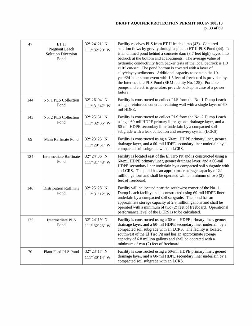
DRAFT AQUIFER PROTECTION PERMIT NO. P- 100510 p. 33 of 69
47 ET II Pregnant Leach
Solution Diversion Pond
32° 24' 21" N 111° 32' 20" W
Facility receives PLS from ET II leach dump (43). Captured solution flows by gravity through a pipe to ET II PLS Pond (44). It is an unlined pond behind a concrete dam (8.7 feet high) keyed into bedrock at the bottom and at abutments. The average value of hydraulic conductivity from packer tests of the local bedrock is 1.0 x10⁻⁵ cm/sec. The pond bottom is covered with a layer of silty/clayey sediments. Additional capacity to contain the 10-year/24-hour storm event with 1.5 feet of freeboard is provided by the Intermediate PLS Pond (SBM facility No. 125). Portable pumps and electric generators provide backup in case of a power failure.
144 No. 1 PLS Collection Pond
32° 26' 04" N 111° 31' 47" W
Facility is constructed to collect PLS from the No. 1 Dump Leach using a reinforced concrete retaining wall with a single layer of 60-mil HDPE.
145 No. 2 PLS Collection Pond
32° 25' 51" N 111° 32' 36" W
Facility is constructed to collect PLS from the No. 2 Dump Leach using a 60-mil HDPE primary liner, geonet drainage layer, and a 60-mil HDPE secondary liner underlain by a compacted soil subgrade with a leak collection and recovery system (LCRS).
69 Main Raffinate Pond 32° 23' 25" N 111° 29' 51" W
Facility is constructed using a 60-mil HDPE primary liner, geonet drainage layer, and a 60-mil HDPE secondary liner underlain by a compacted soil subgrade with an LCRS.
124 Intermediate Raffinate Pond
32° 24' 36" N 111° 31' 43" W
Facility is located east of the El Tiro Pit and is constructed using a 60-mil HDPE primary liner, geonet drainage layer, and a 60-mil HDPE secondary liner underlain by a compacted soil subgrade with an LCRS. The pond has an approximate storage capacity of 2.1 million gallons and shall be operated with a minimum of two (2) feet of freeboard.
146 Distribution Raffinate Pond
32° 25' 28" N 111° 31' 12" W
Facility will be located near the southwest corner of the No. 1 Dump Leach facility and is constructed using 60-mil HDPE liner underlain by a compacted soil subgrade. The pond has an approximate storage capacity of 2.8 million gallons and shall be operated with a minimum of two (2) feet of freeboard. Operational performance level of the LCRS is to be calculated.
125 Intermediate PLS Pond
32° 24' 19" N 111° 32' 23" W
Facility is constructed using a 60-mil HDPE primary liner, geonet drainage layer, and a 60-mil HDPE secondary liner underlain by a compacted soil subgrade with an LCRS. The facility is located southwest of the El Tiro Pit and has an approximate storage capacity of 6.8 million gallons and shall be operated with a minimum of two (2) feet of freeboard.
70 Plant Feed PLS Pond 32° 23' 17" N 111° 30' 14" W
Facility is constructed using a 60-mil HDPE primary liner, geonet drainage layer, and a 60-mil HDPE secondary liner underlain by a compacted soil subgrade with an LCRS.

DRAFT AQUIFER PROTECTION PERMIT NO. P- 100510 p. 34 of 69
156 Mammoth PLS Collection
32° 23' 48" N 111° 31' 27" W
Facility is double-lined with a leak collection and recovery system. Liner design consists of (from bottom to top): six (6) inches of liner bedding material on a compacted subgrade; a GCL (or hydraulic equivalent); an 80-mil HDPE secondary liner; and an 80-mil HDPE primary drain liner. The pond is located adjacent to the MHLF to the southwest. The pond is approximately 3.35 acres in size; approximately 300-feet by 425-feet; 24-feet deep with a minimum of two (2) feet of freeboard; and has a capacity of approximately 36.33 acre-feet (11,800,000 gallons). The total lined area of the pond is 145,760 square feet. The berm slopes are 2.5H:1V for the lined interior and 2H:1V for the unlined exterior. In conjunction with the Mammoth Event Pond, the pond has been designed to hold a 100-year, 24-hour storm event, 24 hours of temporary drain down, and a 24-hour pump outage.
24 Oxide III Pregnant Leach Solution
Pond
32° 23' 32" N 111° 29' 25" W
Facility receives PLS from Oxide III leach dump (23) with overflows diverted to the Oxide III emergency overflow pond (25). It is an unlined pond behind a concrete dam (12 feet high) keyed into bedrock at the bottom and at abutments. The average value of hydraulic conductivity from packer tests of the local bedrock is 7.0 x10⁻⁵ cm/sec. The pond bottom is covered with a layer of silty/clayey sediments. Impounded solution is pumped to either the Plant Feed PLS Pond (70) or Main Raffinate Pond (69). Additional capacity to contain the 10-year/24-hour storm event with 1.5 feet of freeboard is provided by the Oxide III Emergency Overflow Pond (SBM facility No. 25). Portable pumps and electric generators provide backup in case of a power failure. In 2009, this facility was upgraded through the closure of a downgradient mine shaft and the installation of a grout curtain below the concrete dam.
25 Oxide III Emergency Overflow Pond
32° 23' 28" N 111° 29' 26" W
Facility receives PLS overflows from facility 24. It is an unlined pond behind a clay-earthen embankment (15.5 feet high) keyed into bedrock at the bottom and at abutments. The average value of hydraulic conductivity from packer tests of the local bedrock is 7.0 x10⁻⁵ cm/sec. The pond bottom is covered with a layer of silty/clayey sediments. Impounded solution is pumped to the Oxide III PLS Pond (24). With 1.5 feet of freeboard, the 10-year/24-hour storm event is contained. Portable pumps and electric generators provide backup in case of a power failure.
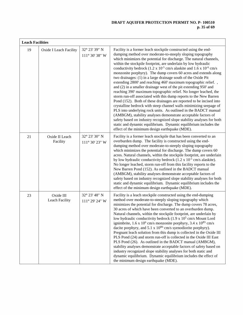
DRAFT AQUIFER PROTECTION PERMIT NO. P- 100510 p. 35 of 69
Leach Facilities
19 Oxide I Leach Facility 32° 23' 39" N 111° 30' 38" W
Facility is a former leach stockpile constructed using the end-dumping method over moderate-to-steeply sloping topography which minimizes the potential for discharge. The natural channels, within the stockpile footprint, are underlain by low hydraulic conductivity bedrock (1.2 x 10⁻⁵ cm/s alaskite and 1.6 x 10⁻⁶ cm/s monzonite porphyry). The dump covers 60 acres and extends along two drainages: (1) in a large drainage south of the Oxide Pit extending 2800' and reaching 460' maximum topographic relief. , and (2) in a smaller drainage west of the pit extending 950' and reaching 390' maximum topographic relief. No longer leached, the storm run-off associated with this dump reports to the New Barren Pond (152). Both of these drainages are reported to be incised into crystalline bedrock with steep channel walls minimizing seepage of PLS into underlying rock units. As outlined in the BADCT manual (AMBGM), stability analyses demonstrate acceptable factors of safety based on industry recognized slope stability analyses for both static and dynamic equilibrium. Dynamic equilibrium includes the effect of the minimum design earthquake (MDE).
21 Oxide II Leach Facility
32° 23' 30" N 111° 30' 23" W
Facility is a former leach stockpile that has been converted to an overburden dump. The facility is constructed using the end-dumping method over moderate-to-steeply sloping topography which minimizes the potential for discharge. The dump covers 60 acres. Natural channels, within the stockpile footprint, are underlain by low hydraulic conductivity bedrock (1.2 x 10⁻⁵ cm/s alaskite). No longer leached, storm run-off from this facility reports to the New Barren Pond (152). As outlined in the BADCT manual (AMBGM), stability analyses demonstrate acceptable factors of safety based on industry recognized slope stability analyses for both static and dynamic equilibrium. Dynamic equilibrium includes the effect of the minimum design earthquake (MDE).
23 Oxide III Leach Facility
32° 23' 48" N 111° 29' 24" W
Facility is a leach stockpile constructed using the end-dumping method over moderate-to-steeply sloping topography which minimizes the potential for discharge. The dump covers 78 acres, 30 acres of which have been converted to an overburden dump. Natural channels, within the stockpile footprint, are underlain by low hydraulic conductivity bedrock (1.9 x 105 cm/s Mount Lord ignimbrite, 1.6 x 106 cm/s monzonite porphyry, 3.4 x 10B5 cm/s dacite porphyry, and 5.1 x 10B6 cm/s syenodiorite porphyry). Pregnant leach solution from this dump is collected in the Oxide III PLS Pond (24) and storm run-off is collected in the Oxide III East PLS Pond (26). As outlined in the BADCT manual (AMBGM), stability analyses demonstrate acceptable factors of safety based on industry recognized slope stability analyses for both static and dynamic equilibrium. Dynamic equilibrium includes the effect of the minimum design earthquake (MDE).

DRAFT AQUIFER PROTECTION PERMIT NO. P- 100510 p. 36 of 69
27 Oxide IV Leach Facility
32° 23' 45" N 111° 30' 49" W
Facility leaching operations ceased prior to 1986. It is a former leach stockpile constructed using the end-dumping method over moderate-to-steeply sloping topography which minimizes the potential for discharge. The dump covers 30 acres. Natural channels, within the stockpile footprint, are underlain by low hydraulic conductivity bedrock (1.2 x 105 cm/s alaskite and 1.6 x 106 cm/s monzonite porphyry). As outlined in the BADCT manual (AMBGM), stability analyses demonstrate acceptable factors of safety based on industry recognized slope stability analyses for both static and dynamic equilibrium. Dynamic equilibrium includes the effect of the minimum design earthquake (MDE).
28 Oxide V Leach Facility
32° 23' 16" N 111° 30' 18" W
Facility leaching operations ceased during 1996. It is a former leach stockpile constructed using the end-dumping method over moderate-to-steeply sloping topography which minimizes the potential for discharge. The dump covers 33 acres. Natural channels, within the stockpile footprint, are underlain by low hydraulic conductivity bedrock (5.7 x 105 cm/s Cretaceous sediments). Storm run-off from this dump is collected in the Oxide V PLS Pond (29) and Oxide V diversion dam (30). As outlined in the BADCT manual (AMBGM), stability analyses demonstrate acceptable factors of safety based on industry recognized slope stability analyses for both static and dynamic equilibrium. Dynamic equilibrium includes the effect of the minimum design earthquake (MDE).
40 ET I Leach Facility
32° 25' 05" N 111° 32' 38" W
Facility leaching operations ceased during 1996. It is a former leach stockpile constructed using the end-dumping method over moderate-to-steeply sloping topography which minimizes the potential for discharge. The dump covers 105 acres. Natural channels, within the stockpile footprint, are underlain by low hydraulic conductivity bedrock (1.0 x 105 cm/s alaskite). As outlined in the BADCT manual (AMBGM), stability analyses demonstrate acceptable factors of safety based on industry recognized slope stability analyses for both static and dynamic equilibrium. Dynamic equilibrium includes the effect of the minimum design earthquake (MDE).
43 ET II Leach Facility
32° 24' 30" N 111° 32' 00" W
Facility is a leach stockpile constructed using the end-dumping method over moderate-to-steeply sloping topography which minimizes the potential for discharge. The dump covers 180 acres. Natural channels, within the stockpile footprint, are underlain by low hydraulic conductivity bedrock (1.1x 105 cm/s alaskite). Pregnant leach solution from this dump is collected in the ET II diversion dam (47), ET II PLS Pond (44), and the El Tiro Pit depending upon leaching location and topography. As outlined in the BADCT manual (AMBGM), stability analyses demonstrate acceptable factors of safety based on industry recognized slope stability analyses for both static and dynamic equilibrium. Dynamic equilibrium includes the effect of the minimum design earthquake (MDE).
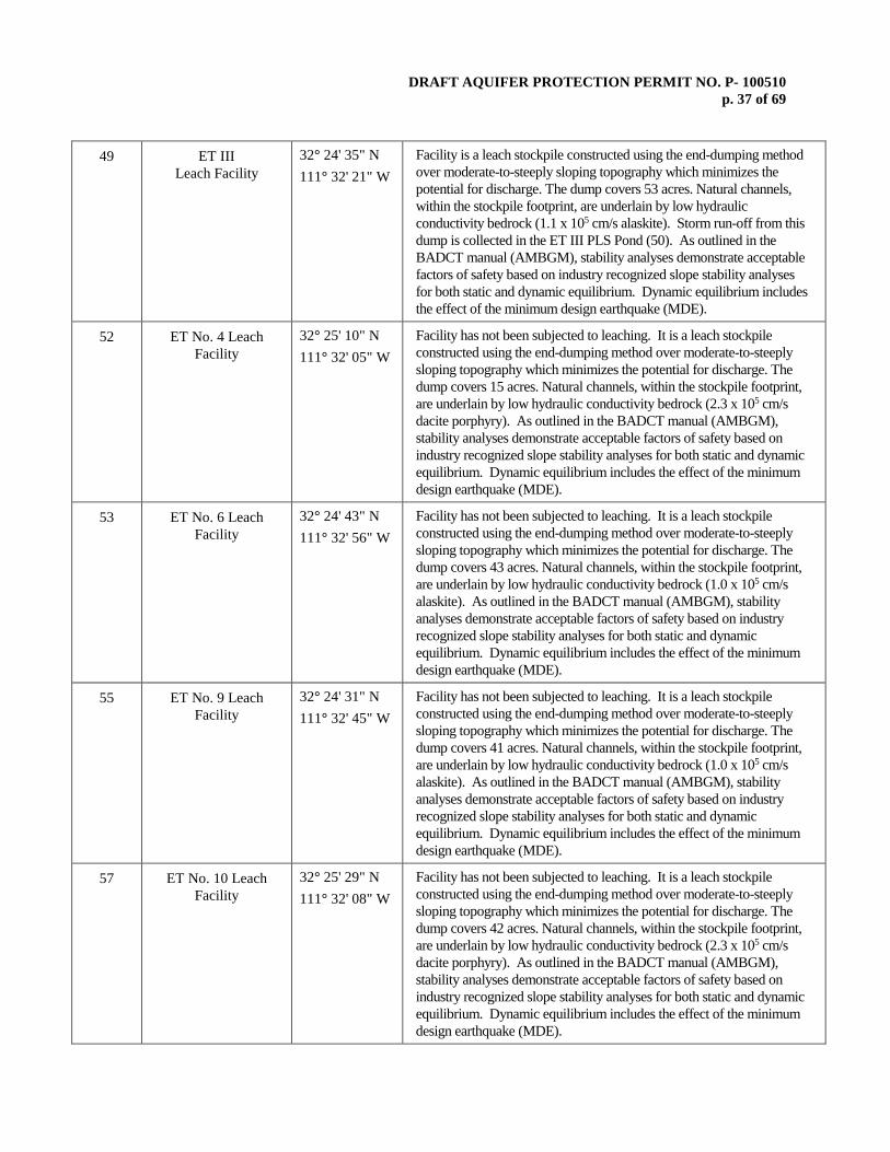
DRAFT AQUIFER PROTECTION PERMIT NO. P- 100510 p. 37 of 69
49 ET III Leach Facility
32° 24' 35" N 111° 32' 21" W
Facility is a leach stockpile constructed using the end-dumping method over moderate-to-steeply sloping topography which minimizes the potential for discharge. The dump covers 53 acres. Natural channels, within the stockpile footprint, are underlain by low hydraulic conductivity bedrock (1.1 x 105 cm/s alaskite). Storm run-off from this dump is collected in the ET III PLS Pond (50). As outlined in the BADCT manual (AMBGM), stability analyses demonstrate acceptable factors of safety based on industry recognized slope stability analyses for both static and dynamic equilibrium. Dynamic equilibrium includes the effect of the minimum design earthquake (MDE).
52 ET No. 4 Leach Facility
32° 25' 10" N 111° 32' 05" W
Facility has not been subjected to leaching. It is a leach stockpile constructed using the end-dumping method over moderate-to-steeply sloping topography which minimizes the potential for discharge. The dump covers 15 acres. Natural channels, within the stockpile footprint, are underlain by low hydraulic conductivity bedrock (2.3 x 105 cm/s dacite porphyry). As outlined in the BADCT manual (AMBGM), stability analyses demonstrate acceptable factors of safety based on industry recognized slope stability analyses for both static and dynamic equilibrium. Dynamic equilibrium includes the effect of the minimum design earthquake (MDE).
53 ET No. 6 Leach Facility
32° 24' 43" N 111° 32' 56" W
Facility has not been subjected to leaching. It is a leach stockpile constructed using the end-dumping method over moderate-to-steeply sloping topography which minimizes the potential for discharge. The dump covers 43 acres. Natural channels, within the stockpile footprint, are underlain by low hydraulic conductivity bedrock (1.0 x 105 cm/s alaskite). As outlined in the BADCT manual (AMBGM), stability analyses demonstrate acceptable factors of safety based on industry recognized slope stability analyses for both static and dynamic equilibrium. Dynamic equilibrium includes the effect of the minimum design earthquake (MDE).
55 ET No. 9 Leach Facility
32° 24' 31" N 111° 32' 45" W
Facility has not been subjected to leaching. It is a leach stockpile constructed using the end-dumping method over moderate-to-steeply sloping topography which minimizes the potential for discharge. The dump covers 41 acres. Natural channels, within the stockpile footprint, are underlain by low hydraulic conductivity bedrock (1.0 x 105 cm/s alaskite). As outlined in the BADCT manual (AMBGM), stability analyses demonstrate acceptable factors of safety based on industry recognized slope stability analyses for both static and dynamic equilibrium. Dynamic equilibrium includes the effect of the minimum design earthquake (MDE).
57 ET No. 10 Leach Facility
32° 25' 29" N 111° 32' 08" W
Facility has not been subjected to leaching. It is a leach stockpile constructed using the end-dumping method over moderate-to-steeply sloping topography which minimizes the potential for discharge. The dump covers 42 acres. Natural channels, within the stockpile footprint, are underlain by low hydraulic conductivity bedrock (2.3 x 105 cm/s dacite porphyry). As outlined in the BADCT manual (AMBGM), stability analyses demonstrate acceptable factors of safety based on industry recognized slope stability analyses for both static and dynamic equilibrium. Dynamic equilibrium includes the effect of the minimum design earthquake (MDE).
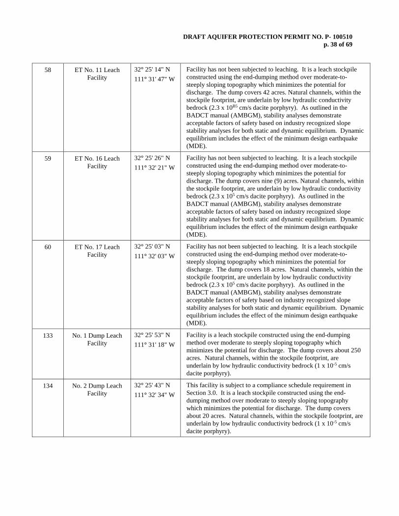
DRAFT AQUIFER PROTECTION PERMIT NO. P- 100510 p. 38 of 69
58 ET No. 11 Leach Facility
32° 25' 14" N 111° 31' 47" W
Facility has not been subjected to leaching. It is a leach stockpile constructed using the end-dumping method over moderate-to-steeply sloping topography which minimizes the potential for discharge. The dump covers 42 acres. Natural channels, within the stockpile footprint, are underlain by low hydraulic conductivity bedrock (2.3 x 10B5 cm/s dacite porphyry). As outlined in the BADCT manual (AMBGM), stability analyses demonstrate acceptable factors of safety based on industry recognized slope stability analyses for both static and dynamic equilibrium. Dynamic equilibrium includes the effect of the minimum design earthquake (MDE).
59 ET No. 16 Leach Facility
32° 25' 26" N 111° 32' 21" W
Facility has not been subjected to leaching. It is a leach stockpile constructed using the end-dumping method over moderate-to-steeply sloping topography which minimizes the potential for discharge. The dump covers nine (9) acres. Natural channels, within the stockpile footprint, are underlain by low hydraulic conductivity bedrock (2.3 x 105 cm/s dacite porphyry). As outlined in the BADCT manual (AMBGM), stability analyses demonstrate acceptable factors of safety based on industry recognized slope stability analyses for both static and dynamic equilibrium. Dynamic equilibrium includes the effect of the minimum design earthquake (MDE).
60 ET No. 17 Leach Facility
32° 25' 03" N 111° 32' 03" W
Facility has not been subjected to leaching. It is a leach stockpile constructed using the end-dumping method over moderate-to-steeply sloping topography which minimizes the potential for discharge. The dump covers 18 acres. Natural channels, within the stockpile footprint, are underlain by low hydraulic conductivity bedrock (2.3 x 105 cm/s dacite porphyry). As outlined in the BADCT manual (AMBGM), stability analyses demonstrate acceptable factors of safety based on industry recognized slope stability analyses for both static and dynamic equilibrium. Dynamic equilibrium includes the effect of the minimum design earthquake (MDE).
133 No. 1 Dump Leach Facility
32° 25' 53" N 111° 31' 18" W
Facility is a leach stockpile constructed using the end-dumping method over moderate to steeply sloping topography which minimizes the potential for discharge. The dump covers about 250 acres. Natural channels, within the stockpile footprint, are underlain by low hydraulic conductivity bedrock (1 x 10⁻⁵ cm/s dacite porphyry).
134 No. 2 Dump Leach Facility
32° 25' 43" N 111° 32' 34" W
This facility is subject to a compliance schedule requirement in Section 3.0. It is a leach stockpile constructed using the end-dumping method over moderate to steeply sloping topography which minimizes the potential for discharge. The dump covers about 20 acres. Natural channels, within the stockpile footprint, are underlain by low hydraulic conductivity bedrock (1 x 10⁻⁵ cm/s dacite porphyry).

DRAFT AQUIFER PROTECTION PERMIT NO. P- 100510 p. 39 of 69
137 North Silver Bell Rubble Leach Facility
32° 25' 56" N 111° 32' 24" W
Rubblized in situ leaching method where PLS reporting to the North Silver Bell Pit, shall rely on passive containment by a North Silver Bell hydrologic sink, other engineered controls, and operational procedures to demonstrate BADCT. Discharge shall be further minimized by using static head reduction.
132 El Tiro Rubble Leach Facility
32° 25' 01" N 111° 32' 32" W
Rubblized in situ leaching method where PLS reporting to the El Tiro Pit, shall rely on passive containment by an El Tiro hydrologic sink, other engineered controls, and operational procedures to demonstrate BADCT. Discharge shall be further minimized by using static head reduction.
66 West Oxide Rubble Leach Facility
32° 25' 57" N 111° 30' 52" W
Rubblized in situ leaching method where PLS reporting to the West Oxide Pit, shall rely on passive containment by a West Oxide hydrologic sink, other engineered controls, and operational procedures to demonstrate BADCT. Discharge may be further minimized by using static head reduction. Rubble leaching has not been conducted in the West Oxide Pit. Prior to performing rubble leaching in this pit, a study demonstrating a predicted passive hydrologic sink must be submitted in accordance with the compliance schedule in Section 3.0.
65 Oxide Rubble Leach Facility
32° 23' 50" N 111° 30' 22" W
Rubblized in situ leaching method where PLS reporting to the Oxide Pit, shall rely on passive containment by an Oxide hydrologic sink, other engineered controls, and operational procedures to demonstrate BADCT. Discharge shall be further minimized by using static head reduction.
155 Mammoth Heap Leach Pad
32° 24' 14" N 111° 31' 26" W
Facility is located in the Mammoth Wash area and has the capacity for 70 to 90 million tons of ore. The total lined area of the pad is 8,694,768 square feet. Facility has a geosynthetic clay liner (GCL) and a geomembrane liner (80-mil textured LLDPE). Facility will be constructed in three phases. Phase 1 will have capacity to store and leach ore for approximately the first three years, Phase 2 for approximately the next five years, and Phase 3 for the remaining years, depending on actual production rates. Ore production is projected to average approximately 15,000 tons per day supplied by run-of-mine (ROM) material. The nominal solution application rate is 3,500 gallons per minute (gpm). The area of the pad will have a maximum stacked ore height of approximately 440 feet, 2H:1V side slopes, and 2.5H:1V slope at the southern end of the pad. The individual ore lifts (20-foot height) will be stacked at the natural angle-of-repose.
Overburden Dumps 39 Overburden Dump No.
39 (North of Oxide Pit)
32° 24' 11" N 111° 30' 15" W
Facility 39 is an overburden stockpile constructed using the end-dumping method over moderate-to-steeply sloping topography which minimizes the potential for discharge. It has not been subjected to leaching.

DRAFT AQUIFER PROTECTION PERMIT NO. P- 100510 p. 40 of 69
61 Overburden Dump (East of East
Extension Pit)
32° 54' 03" N 111° 31' 22" W
Facility 61 is an overburden stockpile constructed using the end-dumping method over moderate-to-steeply sloping topography which minimizes the potential for discharge. It has not been subjected to leaching. As outlined in the BADCT manual (AMBGM), stability analyses demonstrate acceptable factors of safety based on industry accepted slope stability analysis methods for both static and dynamic equilibrium. Dynamic equilibrium includes the effect of the minimum design earthquake (MDE).
62a Overburden Dump (East of ET II Leach
Dump)
32° 24' 35" N 111° 31' 37" W
Facility 62a is an overburden stockpile constructed using the end-dumping method over moderate-to-steeply sloping topography which minimizes the potential for discharge. It has not been subjected to leaching. As outlined in the BADCT manual (AMBGM), stability analyses demonstrate acceptable factors of safety based on industry accepted slope stability analysis methods for both static and dynamic equilibrium. Dynamic equilibrium includes the effect of the minimum design earthquake (MDE).
62b Overburden Dump (East of ET II Leach
Dump)
32° 24' 22" N 111° 31' 50" W
Facility 62b is an overburden stockpile constructed using the end-dumping method over moderate-to-steeply sloping topography which minimizes the potential for discharge. It has not been subjected to leaching. As outlined in the BADCT manual (AMBGM), stability analyses demonstrate acceptable factors of safety based on industry accepted slope stability analysis methods for both static and dynamic equilibrium. Dynamic equilibrium includes the effect of the minimum design earthquake (MDE).
63 Overburden Dump (between ET No.1 and
ET No. 6 Leach Dump)
32° 24' 47" N 111° 32' 45" W
Facility 63 is an overburden stockpile constructed using the end-dumping method over moderate-to-steeply sloping topography which minimizes the potential for discharge. It has not been subjected to leaching. As outlined in the BADCT manual (AMBGM), stability analyses demonstrate acceptable factors of safety based on industry accepted slope stability analysis methods for both static and dynamic equilibrium. Dynamic equilibrium includes the effect of the minimum design earthquake (MDE).
64 Overburden Dump (south of Quartzite
Peak)
32° 25' 20" N 111° 31' 50" W
Facility 64 is an overburden stockpile constructed using the end-dumping method over moderate-to-steeply sloping topography which minimizes the potential for discharge. It has not been subjected to leaching. As outlined in the BADCT manual (AMBGM), stability analyses demonstrate acceptable factors of safety based on industry accepted slope stability analysis methods for both static and dynamic equilibrium. Dynamic equilibrium includes the effect of the minimum design earthquake (MDE).

DRAFT AQUIFER PROTECTION PERMIT NO. P- 100510 p. 41 of 69
13 Overburden Dump No. 13
32° 25' 30" N 111° 31' 33" W
Facility 13 is an overburden dump located directly southwest of the North Silver Bell Dump Leach No.1. The Overburden Dump No. 13 currently contains approximately 45-million tons of overburden and waste rock. The overburden dump is constructed by using the end-dumping method over moderate-to-steep sloping topography. The Overburden Dump No. 13 is located within the North Silver Bell hydrologic sink. The final configuration of the overburden dump will add an additional 12-million tons of overburden and waste rock. The slopes will be approximately 1.5H:1V between the benches with an overall composite slope of 1.7H:1V. As outlined in the BADCT manual, stability analysis for the Overburden Dump No. 13 demonstrated acceptable factors of safety for both static and pseudo-static (dynamic) conditions. Dynamic equilibrium includes the effect of the minimum design earthquake (MDE).
68 West Oxide Overburden Dump
32° 24' 02" N 111° 31' 17" W
Facility 68 is an overburden stockpile constructed using the end-dumping method over moderate-to-steeply sloping topography which minimizes the potential for discharge. The facility is located immediately adjacent to the expanded West Oxide Pit. The West Oxide Overburden Dump will receive overburden, waste rock, and spent ore mined from the expanded West Oxide Pit. The West Oxide Overburden Dump material has been characterized and determined to be acid generating or potentially acid generating. Spent ore and primary waste rock shall be placed in the northern portion of the dump in areas that drain into the West Oxide Pit. Spent ore with the highest acid generation shall be buried within the dump at a minimum of 80-feet in depth. As outlined in the BADCT manual, slope stability analysis demonstrated acceptable factors of safety for both static and dynamic equilibrium. Dynamic equilibrium includes the effect of the minimum design earthquake (MDE).
Non-Municipal Solid Waste Landfill
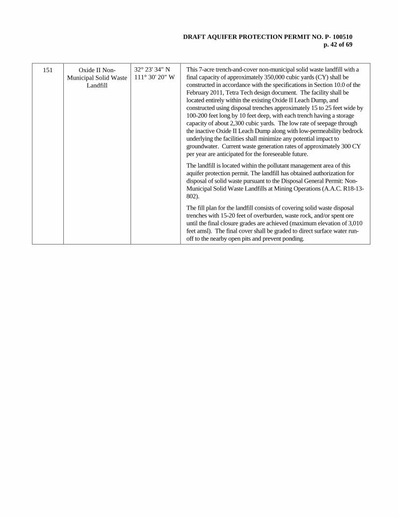
DRAFT AQUIFER PROTECTION PERMIT NO. P- 100510 p. 42 of 69
151 Oxide II Non-Municipal Solid Waste
Landfill
32° 23' 34" N 111° 30' 20" W
This 7-acre trench-and-cover non-municipal solid waste landfill with a final capacity of approximately 350,000 cubic yards (CY) shall be constructed in accordance with the specifications in Section 10.0 of the February 2011, Tetra Tech design document. The facility shall be located entirely within the existing Oxide II Leach Dump, and constructed using disposal trenches approximately 15 to 25 feet wide by 100-200 feet long by 10 feet deep, with each trench having a storage capacity of about 2,300 cubic yards. The low rate of seepage through the inactive Oxide II Leach Dump along with low-permeability bedrock underlying the facilities shall minimize any potential impact to groundwater. Current waste generation rates of approximately 300 CY per year are anticipated for the foreseeable future. The landfill is located within the pollutant management area of this aquifer protection permit. The landfill has obtained authorization for disposal of solid waste pursuant to the Disposal General Permit: Non-Municipal Solid Waste Landfills at Mining Operations (A.A.C. R18-13-802).
The fill plan for the landfill consists of covering solid waste disposal trenches with 15-20 feet of overburden, waste rock, and/or spent ore until the final closure grades are achieved (maximum elevation of 3,010 feet amsl). The final cover shall be graded to direct surface water run-off to the nearby open pits and prevent ponding.

DRAFT AQUIFER PROTECTION PERMIT NO. P- 100510 p. 43 of 69
Vehicle Wash 153 New Truck Wash 32º 26' 02" N
111º 32' 37" W The truck wash facility was constructed to contain all wash water and sediment on a concrete pad and two concrete sedimentation sumps. Sediment is dewatered and removed on a routine basis and transported to the surface of an overburden dump. Excess water is pumped to the North Silver Bell Pit for process make up water and dust control. Oil is skimmed off surface of sumps on a continuous basis and collected for recycling.
Facilities Addressed in the Compliance Schedule 5 Tailings Dam
No. 3 32° 23' 05" N 111° 27' 14" W
Facility 5 construction is not complete with remaining construction to be addressed (see Compliance Schedule Section 3.0). Only the starter dam and associated discharge collection s have been constructed with some work remaining. The design relies on slime sealing to minimize seepage from the tailings pile. Operation startup is deferred until tailings disposal operation is restarted at some undetermined date.
6 Tailings No. 3 Water Reclaim Pond
32° 22' 45" N 111° 26' 49" W
Facility 6 is to receive reclaim water from Tailing Dam No. 3, but construction is not complete with remaining construction to be addressed (see Compliance Schedule Section 3.0). Operation startup is deferred until tailings disposal operation is restarted at some undetermined date.
7 Tailings No. 3 Water Diversion Dam
32° 23' 02" N 111° 26' 53" W
Facility 7 is to receive water collected from Tailings Dam No. 3 under-drain system, but construction is not complete with remaining construction to be addressed (see Compliance Schedule Section 3.0). Operation startup is deferred until tailings disposal operation is restarted at some undetermined date.
8 Tailings No. 3 Water Diversion Dam
32° 22' 55" N 111° 26' 53" W
Facility 8 is to receive water collected from Tailings Dam No. 3 under-drain system, but construction is not complete with remaining construction to be addressed (see Compliance Schedule Section 3.0). Operation startup is deferred until tailings disposal operation is restarted at some undetermined date.
9 Tailings No. 3 Water Diversion Dam
32° 22' 49" N 111° 26' 54" W
Facility 9 is to receive water collected from Tailings Dam No. 3 under-drain system, but construction is not complete with remaining construction to be addressed (see Compliance Schedule Section 3.0). Operation startup is deferred until tailings disposal operation is restarted at some undetermined date.
10 Tailings No. 3 Water Diversion Dam
32° 22' 46" N 111° 26' 57" W
Facility 10 is to receive water collected from Tailings Dam No. 3 under-drain system, but construction is not complete with remaining construction to be addressed (see Compliance Schedule Section 3.0). Operation startup is deferred until tailings disposal operation is restarted at some undetermined date.
11 Tailings No. 3 Water Diversion Dam
32° 22' 41" N 111° 27' 07" W
Facility 11 is to receive water collected from Tailings Dam No. 3 under drain system, but construction is not complete with remaining construction to be addressed (see Compliance Schedule Section 3.0). Operation startup is deferred until tailings disposal operation is restarted at some undetermined date.
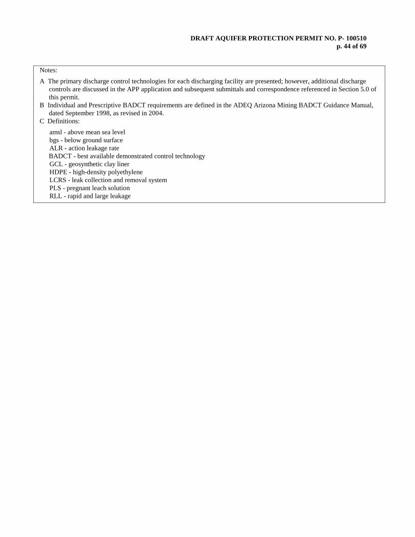
DRAFT AQUIFER PROTECTION PERMIT NO. P- 100510 p. 44 of 69
Notes:
A The primary discharge control technologies for each discharging facility are presented; however, additional discharge controls are discussed in the APP application and subsequent submittals and correspondence referenced in Section 5.0 of this permit.
B Individual and Prescriptive BADCT requirements are defined in the ADEQ Arizona Mining BADCT Guidance Manual, dated September 1998, as revised in 2004.
C Definitions:
amsl - above mean sea level bgs - below ground surface ALR - action leakage rate BADCT - best available demonstrated control technology GCL - geosynthetic clay liner HDPE - high-density polyethylene LCRS - leak collection and removal system PLS - pregnant leach solution RLL - rapid and large leakage

DRAFT AQUIFER PROTECTION PERMIT NO. P- 100510 p. 45 of 69
TABLE 4.2.1 REQUIRED INSPECTIONS AND OPERATIONAL MONITORING
Facility No. Facility Name Operational Requirements Non-storm Water Ponds and Surface Ponds
120 El Tiro Area Drainage No. 9 'A' Stream Storm
Water Pond
Following storm events exceeding 1-inch in a 24-hour period: -Maintain sufficient capacity within each pond and any associated emergency overflow pond to contain the 100-year, 24-hour runoff volume. Where such capacity is insufficient for this, use mobile pumping systems and pipelines to move captured water to larger capacity facilities. Dedicated pumping exists in the 'A', 'B', 'C' and Mill Storm Water Pond to ensure capacity is maintained. -Inspect pumps, pump structures, and access Monthly when facilities contain liquid or are otherwise in use: -Visually inspect liners for cracks, holes, leaks, or tears visible from above the liquid surface and anchor trench integrity; -Visually inspect embankment or containment walls for physical deformations such as surface cracks, slides, sloughs, erosion, unusual settlement, slope failures, etc.; and -Visually inspect the ground surface down-gradient from each facility for the presence of moisture where moisture is not expected to occur based on the intended function and design of the facility as described in SBM’s APP application dated September 6, 1996, and for liquid flows, seeps, surface discoloration, slumping, or other evidence of unauthorized surface or subsurface discharges or leaks.
126 El Tiro Area Drainage No. 12 'B' Stream Storm Water
Pond
131 El Tiro Area Drainage No. 13 'C' Stream Storm Water
Pond 17 Mill Storm Water Pond
154 West Oxide Pond
152 New Barren Pond (near Old Precip. Plant)
26 Oxide III East Pregnant Leach Solution Pond (no
longer receives PLS)
29 Oxide V Pregnant Leach Solution Pond (no longer
receives PLS)
30 Oxide V Pregnant Leach Solution Diversion Pond (no longer receives PLS)
50 ET III Pregnant Leach
Solution Pond (no longer receives PLS)
51 ET III Emergency Overflow
Pond (no longer receives PLS)
31 Oxide V Emergency
Overflow Pond (no longer receives PLS)
157 Mammoth Event Pond
Process Solution Ponds (PLS)
24 Oxide III Pregnant Leach Solution Pond
Daily: -Check overflow pipes for blockages. -Visually inspect and maintain appropriate freeboard in Ponds (see Table 4.1, Permitted Facilities and BADCT) -For Diversion Structures, check screens for blockages, as applicable. Weekly: -For pump-back systems, check pump operation and perform maintenance. -Test the pumps associated with any leak detection sumps to verify that
25 Oxide III Emergency Overflow Pond
41 ET I Pregnant Leach Solution Pond
42 ET I Emergency Overflow Pond
44 ET II Pregnant Leach Solution Pond
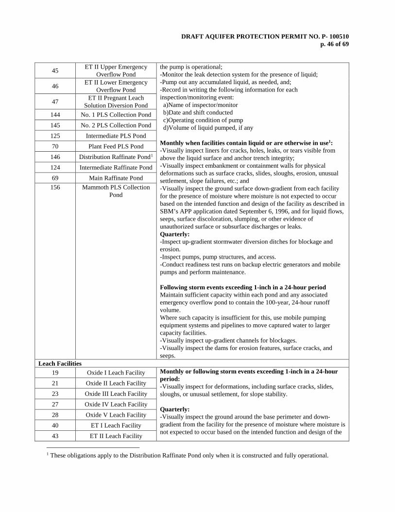
DRAFT AQUIFER PROTECTION PERMIT NO. P- 100510 p. 46 of 69
45 ET II Upper Emergency Overflow Pond
the pump is operational; -Monitor the leak detection system for the presence of liquid; -Pump out any accumulated liquid, as needed, and; -Record in writing the following information for each inspection/monitoring event: a)Name of inspector/monitor b)Date and shift conducted c)Operating condition of pump d)Volume of liquid pumped, if any Monthly when facilities contain liquid or are otherwise in use1: -Visually inspect liners for cracks, holes, leaks, or tears visible from above the liquid surface and anchor trench integrity; -Visually inspect embankment or containment walls for physical deformations such as surface cracks, slides, sloughs, erosion, unusual settlement, slope failures, etc.; and -Visually inspect the ground surface down-gradient from each facility for the presence of moisture where moisture is not expected to occur based on the intended function and design of the facility as described in SBM’s APP application dated September 6, 1996, and for liquid flows, seeps, surface discoloration, slumping, or other evidence of unauthorized surface or subsurface discharges or leaks. Quarterly: -Inspect up-gradient stormwater diversion ditches for blockage and erosion. -Inspect pumps, pump structures, and access. -Conduct readiness test runs on backup electric generators and mobile pumps and perform maintenance. Following storm events exceeding 1-inch in a 24-hour period Maintain sufficient capacity within each pond and any associated emergency overflow pond to contain the 100-year, 24-hour runoff volume. Where such capacity is insufficient for this, use mobile pumping equipment systems and pipelines to move captured water to larger capacity facilities. -Visually inspect up-gradient channels for blockages. -Visually inspect the dams for erosion features, surface cracks, and seeps.
46 ET II Lower Emergency Overflow Pond
47 ET II Pregnant Leach Solution Diversion Pond
144 No. 1 PLS Collection Pond 145 No. 2 PLS Collection Pond 125 Intermediate PLS Pond 70 Plant Feed PLS Pond
146 Distribution Raffinate Pond1 124 Intermediate Raffinate Pond 69 Main Raffinate Pond
156 Mammoth PLS Collection Pond
Leach Facilities 19 Oxide I Leach Facility Monthly or following storm events exceeding 1-inch in a 24-hour
period: -Visually inspect for deformations, including surface cracks, slides, sloughs, or unusual settlement, for slope stability. Quarterly: -Visually inspect the ground around the base perimeter and down-gradient from the facility for the presence of moisture where moisture is not expected to occur based on the intended function and design of the
21 Oxide II Leach Facility 23 Oxide III Leach Facility 27 Oxide IV Leach Facility 28 Oxide V Leach Facility 40 ET I Leach Facility 43 ET II Leach Facility
1 These obligations apply to the Distribution Raffinate Pond only when it is constructed and fully operational.

DRAFT AQUIFER PROTECTION PERMIT NO. P- 100510 p. 47 of 69
49 ET III Leach Facility facility as described in SBM’s APP application dated September 6, 1996 (pre-1986 facilities). 52 ET No. 4 Leach Facility
53 ET No. 6 Leach Facility 55 ET No. 9 Leach Facility 57 ET No. 10 Leach Facility 58 ET No. 11 Leach Facility 59 ET No. 16 Leach Facility 60 ET No. 17 Leach Facility
133 No. 1 Dump Leach Facility 134 No. 2 Dump Leach Facility
137 North Silver Bell Rubble Leach Facility
132 El Tiro Rubble Leach Facility
66 West Oxide Rubble Leach Facility
65 Oxide Rubble Leach Facility
155 Mammoth Heap Leach Pad Overburden Stockpiles, Non-Municipal Solid Waste Landfill and New Truck Wash
39 Overburden Dump No. 39(North of Oxide Pit)
Monthly or following storm events exceeding 1-inch in a 24-hour period: Visually inspect for deformations, including surface cracks, slides, sloughs, or unusual settlement, for slope stability.
61 Overburden Dump (East of East Extension Pit)
62a Overburden Dump (East of ET II Leach Dump)
13 Overburden Dump No. 13
62b Overburden Dump (East of ET II Leach Dump)
63 Overburden Dump (between
ET No.1 and ET No. 6 Leach Dump)
64 Overburden Dump (south of Quartzite Peak
68 West Oxide Overburden Dump
153 New Truck Wash
After sump clean out: Inspect integrity of concrete in sumps and perform maintenance on an as-needed basis. Monthly: Check oil skimmer function and perform maintenance on an as-needed basis.
Facilities addressed in the Compliance Schedule

DRAFT AQUIFER PROTECTION PERMIT NO. P- 100510 p. 48 of 69
5 Tailings Dam No. 3 GENERAL REQUIREMENTS ONCE FACILITY IS CONSTRUCTED AND OPERATIONAL
Daily: -During periods of operation, maintain an appropriate beach distance and freeboard as dictated by construction plans. -Insure that pipelines (i.e., cyclones underflow pipelines, thickener pipelines, etc.) are properly positioned to maintain flow into the tailings Pond. -Maintain access to tailings ponds. -Visually inspect the water reclaim system for blockage. -Following storm events exceeding at least 1-inch in a 24-hour period, reestablish appropriate beach and freeboard within 48 hours
Monthly: -Visually inspect liners for cracks, holes, leaks, or tears from above the liquid surface; -Visually inspect embankment or containment walls for physical deformations such as surface cracks, slides, sloughs, erosion, unusual settlement, slope failures, etc.; and -Visually inspect the ground surface down-gradient from each facility for liquid flows, seeps, surface discoloration, slumping or other evidence of unauthorized surface or subsurface discharges or leaks.
Quarterly: -Inspect for crest failure, translation of toe or sloughing. -Note visible cracks or erosion features and perform maintenance. -Check for seepage from toe and face of tailings pond. -While in operation and during the first year following temporary cessation of tailings ponds, measure water levels in slope stability piezometers to ensure phreatic surface is maintained within safe operating limits.
Annually: -During the second and subsequent years following temporary cessation of tailing Pond, measure water levels in slope stability piezometers to ensure phreatic surface is maintained within safe operating limits.
6 Tailings No. 3 Water Reclaim Pond
Following storm events exceeding one (1) inch in a 24-hour period: -Reestablish, within 72 hours, sufficient capacity within each dam system to contain the 100-year, 24-hour runoff volume. -Visually inspect upgradient channels for blockages. -Visually inspect the dams for erosion features, surface cracks and seeps. -Visually inspect and maintain appropriate freeboard.
Quarterly: -Inspect embankment integrity, pumps, pump structures, and access. -Visually inspect liners for holes and tears, and anchor trench integrity (clay or HDPE liners, as applicable).
Annually: Remove access silt/slimes from behind embankments as needed to maintain storage capacity.
7 Tailings No. 3 Water Diversion Dam
8 Tailings No. 3 Water Diversion Dam
9 Tailings No. 3 Water Diversion Dam
10 Tailings No. 3 Water Diversion Dam
11 Tailings No. 3 Water Diversion Dam

DRAFT AQUIFER PROTECTION PERMIT NO. P- 100510 p. 49 of 69
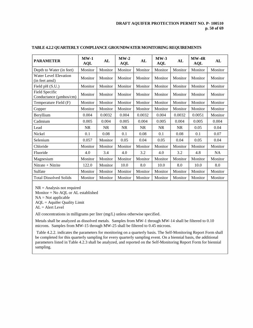
DRAFT AQUIFER PROTECTION PERMIT NO. P- 100510 p. 50 of 69
TABLE 4.2.2 QUARTERLY COMPLIANCE GROUNDWATER MONITORING REQUIREMENTS
PARAMETER MW-1 AQL AL MW-2
AQL AL MW-3 AQL AL MW-4R
AQL AL
Depth to Water (in feet) Monitor Monitor Monitor Monitor Monitor Monitor Monitor Monitor Water Level Elevation (in feet amsl) Monitor Monitor Monitor Monitor Monitor Monitor Monitor Monitor
Field pH (S.U.) Monitor Monitor Monitor Monitor Monitor Monitor Monitor Monitor Field Specific Conductance (µmhos/cm) Monitor Monitor Monitor Monitor Monitor Monitor Monitor Monitor
Temperature Field (F) Monitor Monitor Monitor Monitor Monitor Monitor Monitor Monitor Copper Monitor Monitor Monitor Monitor Monitor Monitor Monitor Monitor Beryllium 0.004 0.0032 0.004 0.0032 0.004 0.0032 0.0051 Monitor Cadmium 0.005 0.004 0.005 0.004 0.005 0.004 0.005 0.004 Lead NR NR NR NR NR NR 0.05 0.04 Nickel 0.1 0.08 0.1 0.08 0.1 0.08 0.1 0.07 Selenium 0.057 Monitor 0.05 0.04 0.05 0.04 0.05 0.04 Chloride Monitor Monitor Monitor Monitor Monitor Monitor Monitor Monitor Fluoride 4.0 3.4 4.0 3.2 4.0 3.2 4.8 NA Magnesium Monitor Monitor Monitor Monitor Monitor Monitor Monitor Monitor Nitrate + Nitrite 122.0 Monitor 10.0 8.0 10.0 8.0 10.0 8.0 Sulfate Monitor Monitor Monitor Monitor Monitor Monitor Monitor Monitor Total Dissolved Solids Monitor Monitor Monitor Monitor Monitor Monitor Monitor Monitor
NR = Analysis not required Monitor = No AQL or AL established NA = Not applicable AQL = Aquifer Quality Limit AL = Alert Level
All concentrations in milligrams per liter (mg/L) unless otherwise specified.
Metals shall be analyzed as dissolved metals. Samples from MW-1 through MW-14 shall be filtered to 0.10 microns. Samples from MW-15 through MW-25 shall be filtered to 0.45 microns.
Table 4.2.2. indicates the parameters for monitoring on a quarterly basis. The Self-Monitoring Report Form shall be completed for this quarterly sampling for every quarterly sampling event. On a biennial basis, the additional parameters listed in Table 4.2.3 shall be analyzed, and reported on the Self-Monitoring Report Form for biennial sampling.
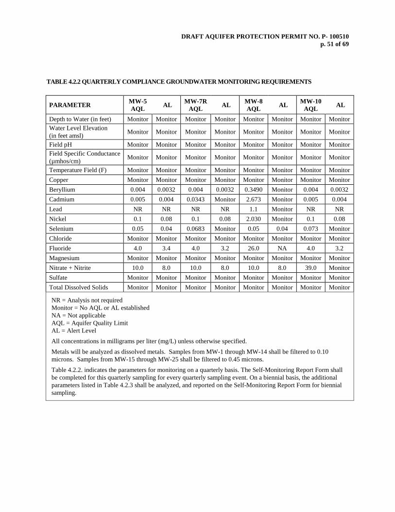
DRAFT AQUIFER PROTECTION PERMIT NO. P- 100510 p. 51 of 69
TABLE 4.2.2 QUARTERLY COMPLIANCE GROUNDWATER MONITORING REQUIREMENTS
PARAMETER MW-5 AQL AL MW-7R
AQL AL MW-8 AQL AL MW-10
AQL AL
Depth to Water (in feet) Monitor Monitor Monitor Monitor Monitor Monitor Monitor Monitor Water Level Elevation (in feet amsl) Monitor Monitor Monitor Monitor Monitor Monitor Monitor Monitor
Field pH Monitor Monitor Monitor Monitor Monitor Monitor Monitor Monitor Field Specific Conductance (µmhos/cm) Monitor Monitor Monitor Monitor Monitor Monitor Monitor Monitor
Temperature Field (F) Monitor Monitor Monitor Monitor Monitor Monitor Monitor Monitor Copper Monitor Monitor Monitor Monitor Monitor Monitor Monitor Monitor Beryllium 0.004 0.0032 0.004 0.0032 0.3490 Monitor 0.004 0.0032 Cadmium 0.005 0.004 0.0343 Monitor 2.673 Monitor 0.005 0.004 Lead NR NR NR NR 1.1 Monitor NR NR Nickel 0.1 0.08 0.1 0.08 2.030 Monitor 0.1 0.08 Selenium 0.05 0.04 0.0683 Monitor 0.05 0.04 0.073 Monitor Chloride Monitor Monitor Monitor Monitor Monitor Monitor Monitor Monitor Fluoride 4.0 3.4 4.0 3.2 26.0 NA 4.0 3.2 Magnesium Monitor Monitor Monitor Monitor Monitor Monitor Monitor Monitor Nitrate + Nitrite 10.0 8.0 10.0 8.0 10.0 8.0 39.0 Monitor Sulfate Monitor Monitor Monitor Monitor Monitor Monitor Monitor Monitor Total Dissolved Solids Monitor Monitor Monitor Monitor Monitor Monitor Monitor Monitor
NR = Analysis not required Monitor = No AQL or AL established NA = Not applicable AQL = Aquifer Quality Limit AL = Alert Level
All concentrations in milligrams per liter (mg/L) unless otherwise specified.
Metals will be analyzed as dissolved metals. Samples from MW-1 through MW-14 shall be filtered to 0.10 microns. Samples from MW-15 through MW-25 shall be filtered to 0.45 microns.
Table 4.2.2. indicates the parameters for monitoring on a quarterly basis. The Self-Monitoring Report Form shall be completed for this quarterly sampling for every quarterly sampling event. On a biennial basis, the additional parameters listed in Table 4.2.3 shall be analyzed, and reported on the Self-Monitoring Report Form for biennial sampling.

DRAFT AQUIFER PROTECTION PERMIT NO. P- 100510 p. 52 of 69
TABLE 4.2.2 QUARTERLY COMPLIANCE GROUNDWATER MONITORING REQUIREMENTS
PARAMETER MW-11R AQL AL MW-12
AQL AL MW-14 AQL AL
Depth to Water (in feet) Monitor Monitor Monitor Monitor Monitor Monitor Water Level Elevation (in feet amsl) Monitor Monitor Monitor Monitor Monitor Monitor
Field pH Monitor Monitor Monitor Monitor Monitor Monitor Field Specific Conductance (µmhos/cm) Monitor Monitor Monitor Monitor Monitor Monitor
Temperature Field (F) Monitor Monitor Monitor Monitor Monitor Monitor Copper Monitor Monitor Monitor Monitor Monitor Monitor Beryllium 0.004 0.0032 0.004 0.0032 0.004 0.0032 Cadmium 0.005 0.004 0.005 0.004 0.005 0.004 Lead 0.05 0.04 NR NR NR NR Nickel 0.1 0.08 0.1 0.08 0.243 Monitor Selenium 0.05 0.04. 0.05 0.04 0.05 0.04 Chloride Monitor Monitor Monitor Monitor Monitor Monitor Fluoride 4.0 3.2 4.0 3.2 4.0 3.2 Magnesium Monitor Monitor Monitor Monitor Monitor Monitor Nitrate + Nitrite 10.0 8.0 10.0 8.0 10.0 8.0 Sulfate Monitor Monitor Monitor Monitor Monitor Monitor Total Dissolved Solids Monitor Monitor Monitor Monitor Monitor Monitor
NR = Analysis not required Monitor = No AQL or AL established in permit AQL = Aquifer Quality Limit AL = Alert Level
All concentrations in milligrams per liter (mg/L) unless otherwise specified.
Metals will be analyzed as dissolved metals. Samples from MW-1 through MW-14 shall be filtered to 0.10 microns. Samples from MW-15 through MW-25 shall be filtered to 0.45 microns.
Table 4.2.2. indicates the parameters for monitoring on a quarterly basis. The Self-Monitoring Report Form shall be completed for this quarterly sampling for every quarterly sampling event. On a biennial basis, the additional parameters listed in Table 4.2.3 shall be analyzed, and reported on the Self-Monitoring Report Form for biennial sampling.

DRAFT AQUIFER PROTECTION PERMIT NO. P- 100510 p. 53 of 69
TABLE 4.2.2 QUARTERLY COMPLIANCE GROUNDWATER MONITORING REQUIREMENTS
PARAMETER MW-13 AQL AL MW-15
AQL AL MW-16 AQL AL MW-17
AQL AL
Depth to Water (in feet) Monitor Monitor Monitor Monitor Monitor Monitor Monitor Monitor Water Level Elevation (in feet amsl) Monitor Monitor Monitor Monitor Monitor Monitor Monitor Monitor
Field pH (S.U.) Monitor Res. Monitor Monitor Monitor Monitor Monitor Monitor Field Specific Conductance (µmhos/cm)
Monitor Monitor Monitor Monitor Monitor Monitor Monitor Monitor
Temperature Field (°F) Monitor Monitor Monitor Monitor Monitor Monitor Monitor Monitor Copper Monitor Monitor Monitor Monitor Monitor Monitor Monitor Monitor Beryllium Res. Res. 0.0040 0.0032 0.0040 0.0032 0.0040 0.0032 Cadmium Res. Res. 0.005 0.004 0.005 0.004 0.005 0.004 Lead Res. Res. 0.05 0.04 0.05 0.04 0.05 0.04 Nickel Res. Res. 0.10 0.08 0.10 0.08 0.10 0.08 Selenium Res. Res. 0.05 0.04 0.068 None 0.05 0.04 Fluoride Res. Res. 4.0 3.2 4.0 3.2 4.0 3.2 Magnesium Monitor Monitor Monitor Monitor Monitor Monitor Monitor Monitor Nitrate + Nitrite Res. Res. 10.0 8.0 10.0 9.0 10.0 8.0 Sulfate* Monitor Monitor Monitor Monitor Monitor Monitor Monitor Monitor Total Dissolved Solids Monitor Monitor Monitor Monitor Monitor Monitor Monitor Monitor
Res. = Reserved. This pertains to installation of MW-13, which is contingent on resuming construction of Tailings Dam No. 3 (see Compliance Schedule Item No. 4). At the conclusion of eight (8) rounds of quarterly groundwater sampling, the permittee is required to submit an Ambient Groundwater Monitoring Report and permit amendment request to ADEQ to propose ALs and AQLs based on ambient data. The permit will be amended at the conclusion of Ambient Groundwater Monitoring to establish reserved values.
Monitor = No AQL or AL established AQL = Aquifer Quality Limit AL = Alert Level
All concentrations in milligrams per liter (mg/L) unless otherwise specified.
Metals will be analyzed as dissolved metals. Samples from MW-1 through MW-14 shall be filtered to 0.10 microns. Samples from MW-15 through MW-25 shall be filtered to 0.45 microns.
Table 4.2.2. indicates the parameters for monitoring on a quarterly basis. The Self-Monitoring Report Form shall be completed for this quarterly sampling for every quarterly sampling event. On a biennial basis, the additional parameters listed in Table 4.2.3 shall be analyzed, and reported on the Self-Monitoring Report Form for biennial sampling.
*Trend analysis monitoring and reporting for sulfate shall be conducted in accordance with Section 2.5.3.3.1.

DRAFT AQUIFER PROTECTION PERMIT NO. P- 100510 p. 54 of 69
TABLE 4.2.2 QUARTERLY COMPLIANCE GROUNDWATER MONITORING REQUIREMENTS
PARAMETER MW-18 AQL AL MW-19
AQL AL MW-20 AQL AL MW-21
AQL AL
Depth to Water (in feet) Monitor Monitor Monitor Monitor Monitor Monitor Monitor Monitor Water Level Elevation (in feet amsl) Monitor Monitor Monitor Monitor Monitor Monitor Monitor Monitor
Field pH (S.U.) Monitor Monitor Monitor Monitor Monitor Monitor Monitor Monitor Field Specific Conductance (µmhos/cm)
Monitor Monitor Monitor Monitor Monitor Monitor Monitor Monitor
Temperature Field (°F) Monitor Monitor Monitor Monitor Monitor Monitor Monitor Monitor Copper Monitor Monitor Monitor Monitor Monitor Monitor Monitor Monitor Beryllium 0.0040 0.0032 0.0040 0.0032 0.0040 0.0032 0.0040 0.0032 Cadmium 0.005 0.004 0.0062 Monitor 0.005 0.004 0.005 0.004 Lead 0.05 0.04 0.05 0.04 0.05 0.04 0.05 0.04 Nickel 0.10 0.08 0.10 0.08 0.160 None 0.10 0.08 Selenium 0.05 0.04 0.05 0.04 0.05 0.04 0.05 0.04 Fluoride 4.0 3.2 4.0 3.2 4.0 3.2 4.0 3.2 Magnesium Monitor Monitor Monitor Monitor Monitor Monitor Monitor Monitor Nitrate + Nitrite 10.0 8.0 10.0 8.0 10.0 9.2 10.0 9.3 Sulfate* Monitor Monitor Monitor Monitor Monitor Monitor Monitor Monitor Total Dissolved Solids Monitor Monitor Monitor Monitor Monitor Monitor Monitor Monitor
Monitor = No AQL or AL established AQL = Aquifer Quality Limit AL = Alert Level
All concentrations in milligrams per liter (mg/L) unless otherwise specified.
Metals will be analyzed as dissolved metals. Samples from MW-1 through MW-14 shall be filtered to 0.10 microns. Samples from MW-15 through MW-25 shall be filtered to 0.45 microns.
Table 4.2.2. indicates the parameters for monitoring on a quarterly basis. The Self-Monitoring Report Form shall be completed for this quarterly sampling for every quarterly sampling event. On a biennial basis, the additional parameters listed in Table 4.2.3 shall be analyzed, and reported on the Self-Monitoring Report Form for biennial sampling.
*Trend analysis monitoring and reporting for sulfate shall be conducted in accordance with Section 2.5.3.3.1.
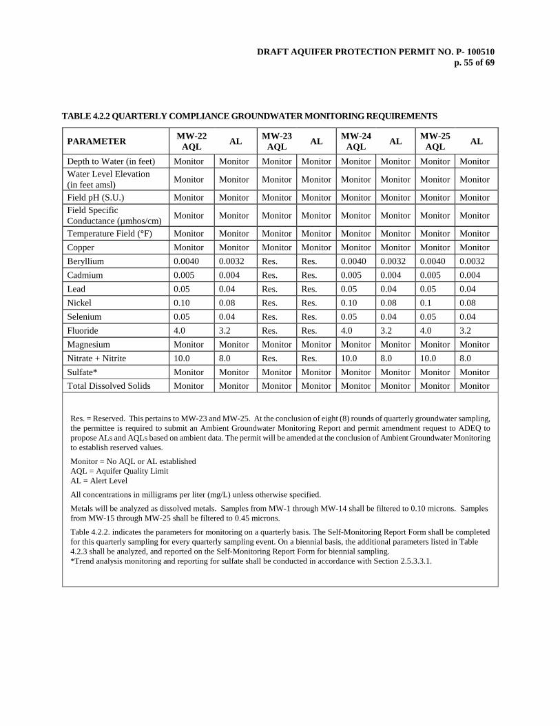
DRAFT AQUIFER PROTECTION PERMIT NO. P- 100510 p. 55 of 69
TABLE 4.2.2 QUARTERLY COMPLIANCE GROUNDWATER MONITORING REQUIREMENTS
PARAMETER MW-22 AQL AL MW-23
AQL AL MW-24 AQL AL MW-25
AQL AL
Depth to Water (in feet) Monitor Monitor Monitor Monitor Monitor Monitor Monitor Monitor Water Level Elevation (in feet amsl) Monitor Monitor Monitor Monitor Monitor Monitor Monitor Monitor
Field pH (S.U.) Monitor Monitor Monitor Monitor Monitor Monitor Monitor Monitor Field Specific Conductance (µmhos/cm) Monitor Monitor Monitor Monitor Monitor Monitor Monitor Monitor
Temperature Field (°F) Monitor Monitor Monitor Monitor Monitor Monitor Monitor Monitor Copper Monitor Monitor Monitor Monitor Monitor Monitor Monitor Monitor Beryllium 0.0040 0.0032 Res. Res. 0.0040 0.0032 0.0040 0.0032 Cadmium 0.005 0.004 Res. Res. 0.005 0.004 0.005 0.004 Lead 0.05 0.04 Res. Res. 0.05 0.04 0.05 0.04 Nickel 0.10 0.08 Res. Res. 0.10 0.08 0.1 0.08 Selenium 0.05 0.04 Res. Res. 0.05 0.04 0.05 0.04 Fluoride 4.0 3.2 Res. Res. 4.0 3.2 4.0 3.2 Magnesium Monitor Monitor Monitor Monitor Monitor Monitor Monitor Monitor Nitrate + Nitrite 10.0 8.0 Res. Res. 10.0 8.0 10.0 8.0 Sulfate* Monitor Monitor Monitor Monitor Monitor Monitor Monitor Monitor Total Dissolved Solids Monitor Monitor Monitor Monitor Monitor Monitor Monitor Monitor
Res. = Reserved. This pertains to MW-23 and MW-25. At the conclusion of eight (8) rounds of quarterly groundwater sampling, the permittee is required to submit an Ambient Groundwater Monitoring Report and permit amendment request to ADEQ to propose ALs and AQLs based on ambient data. The permit will be amended at the conclusion of Ambient Groundwater Monitoring to establish reserved values.
Monitor = No AQL or AL established AQL = Aquifer Quality Limit AL = Alert Level
All concentrations in milligrams per liter (mg/L) unless otherwise specified.
Metals will be analyzed as dissolved metals. Samples from MW-1 through MW-14 shall be filtered to 0.10 microns. Samples from MW-15 through MW-25 shall be filtered to 0.45 microns.
Table 4.2.2. indicates the parameters for monitoring on a quarterly basis. The Self-Monitoring Report Form shall be completed for this quarterly sampling for every quarterly sampling event. On a biennial basis, the additional parameters listed in Table 4.2.3 shall be analyzed, and reported on the Self-Monitoring Report Form for biennial sampling.
*Trend analysis monitoring and reporting for sulfate shall be conducted in accordance with Section 2.5.3.3.1.
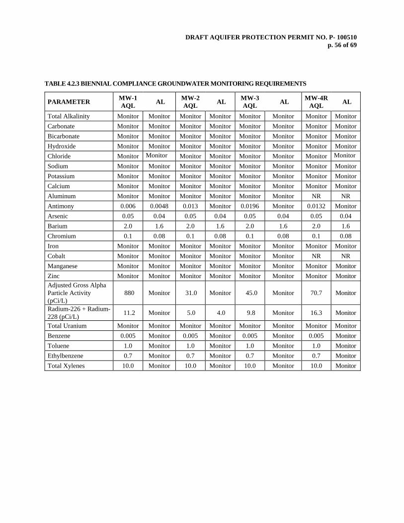
DRAFT AQUIFER PROTECTION PERMIT NO. P- 100510 p. 56 of 69
TABLE 4.2.3 BIENNIAL COMPLIANCE GROUNDWATER MONITORING REQUIREMENTS
PARAMETER MW-1 AQL AL MW-2
AQL AL MW-3 AQL AL MW-4R
AQL AL
Total Alkalinity Monitor Monitor Monitor Monitor Monitor Monitor Monitor Monitor Carbonate Monitor Monitor Monitor Monitor Monitor Monitor Monitor Monitor Bicarbonate Monitor Monitor Monitor Monitor Monitor Monitor Monitor Monitor Hydroxide Monitor Monitor Monitor Monitor Monitor Monitor Monitor Monitor Chloride Monitor Monitor Monitor Monitor Monitor Monitor Monitor Monitor Sodium Monitor Monitor Monitor Monitor Monitor Monitor Monitor Monitor Potassium Monitor Monitor Monitor Monitor Monitor Monitor Monitor Monitor Calcium Monitor Monitor Monitor Monitor Monitor Monitor Monitor Monitor Aluminum Monitor Monitor Monitor Monitor Monitor Monitor NR NR Antimony 0.006 0.0048 0.013 Monitor 0.0196 Monitor 0.0132 Monitor Arsenic 0.05 0.04 0.05 0.04 0.05 0.04 0.05 0.04 Barium 2.0 1.6 2.0 1.6 2.0 1.6 2.0 1.6 Chromium 0.1 0.08 0.1 0.08 0.1 0.08 0.1 0.08 Iron Monitor Monitor Monitor Monitor Monitor Monitor Monitor Monitor Cobalt Monitor Monitor Monitor Monitor Monitor Monitor NR NR Manganese Monitor Monitor Monitor Monitor Monitor Monitor Monitor Monitor Zinc Monitor Monitor Monitor Monitor Monitor Monitor Monitor Monitor Adjusted Gross Alpha Particle Activity (pCi/L)
880 Monitor 31.0 Monitor 45.0 Monitor 70.7 Monitor
Radium-226 + Radium-228 (pCi/L) 11.2 Monitor 5.0 4.0 9.8 Monitor 16.3 Monitor
Total Uranium Monitor Monitor Monitor Monitor Monitor Monitor Monitor Monitor Benzene 0.005 Monitor 0.005 Monitor 0.005 Monitor 0.005 Monitor Toluene 1.0 Monitor 1.0 Monitor 1.0 Monitor 1.0 Monitor Ethylbenzene 0.7 Monitor 0.7 Monitor 0.7 Monitor 0.7 Monitor Total Xylenes 10.0 Monitor 10.0 Monitor 10.0 Monitor 10.0 Monitor
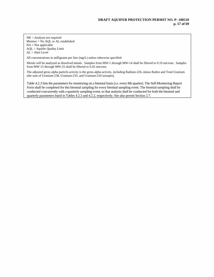
DRAFT AQUIFER PROTECTION PERMIT NO. P- 100510 p. 57 of 69
NR = Analysis not required Monitor = No AQL or AL established NA = Not applicable AQL = Aquifer Quality Limit AL = Alert Level
All concentrations in milligrams per liter (mg/L) unless otherwise specified.
Metals will be analyzed as dissolved metals. Samples from MW-1 through MW-14 shall be filtered to 0.10 microns. Samples from MW-15 through MW-25 shall be filtered to 0.45 microns.
The adjusted gross alpha particle activity is the gross alpha activity, including Radium-226, minus Radon and Total Uranium (the sum of Uranium-238, Uranium-235, and Uranium-234 isotopes). Table 4.2.3 lists the parameters for monitoring on a biennial basis (i.e. every 8th quarter). The Self-Monitoring Report Form shall be completed for this biennial sampling for every biennial sampling event. The biennial sampling shall be conducted concurrently with a quarterly sampling event, so that analysis shall be conducted for both the biennial and quarterly parameters listed in Tables 4.2.3 and 4.2.2, respectively. See also permit Section 2.7.

DRAFT AQUIFER PROTECTION PERMIT NO. P- 100510 p. 58 of 69
TABLE 4.2.3 BIENNIAL COMPLIANCE GROUNDWATER MONITORING REQUIREMENTS
PARAMETER MW-5 AQL AL MW-7R
AQL AL MW-8 AQL AL MW-10
AQL AL
Total Alkalinity Monitor Monitor Monitor Monitor Monitor Monitor Monitor Monitor Carbonate Monitor Monitor Monitor Monitor Monitor Monitor Monitor Monitor Bicarbonate Monitor Monitor Monitor Monitor Monitor Monitor Monitor Monitor Hydroxide Monitor Monitor Monitor Monitor Monitor Monitor Monitor Monitor Chloride Monitor Monitor Monitor Monitor Monitor Monitor Monitor Monitor Sodium Monitor Monitor Monitor Monitor Monitor Monitor Monitor Monitor Potassium Monitor Monitor Monitor Monitor Monitor Monitor Monitor Monitor Calcium Monitor Monitor Monitor Monitor Monitor Monitor Monitor Monitor Aluminum NR NR Monitor Monitor Monitor Monitor Monitor Monitor Antimony 0.0083 Monitor 0.028 Monitor 0.006 0.0048 0.006 0.0048 Arsenic 0.05 0.04 0.05 0.04 0.05 0.04 0.05 0.04 Barium 2.0 1.6 2.0 1.6 2.0 1.6 2.0 1.6 Chromium 0.1 0.08 0.1 0.08 0.1 0.08 0.1 0.08 Iron Monitor Monitor Monitor Monitor Monitor Monitor Monitor Monitor Thallium NR NR NR NR NR NR NR NR Cobalt NR NR Monitor Monitor Monitor Monitor Monitor Monitor Manganese Monitor Monitor Monitor Monitor Monitor Monitor Monitor Monitor Zinc Monitor Monitor Monitor Monitor Monitor Monitor Monitor Monitor Adjusted Gross Alpha Particle Activity (pCi/L) 70.0 Monitor 1840 Monitor 488 Monitor 166.1 Monitor
Radium-226 + Radium-228 (pCi/L) 5.0 4.0 7.0 Monitor 39.2 Monitor 9.6 Monitor
Total Uranium Monitor Monitor Monitor Monitor Monitor Monitor Monitor Monitor Benzene 0.005 Monitor 0.005 Monitor 0.005 Monitor 0.005 Monitor Toluene 1.0 Monitor 1.0 Monitor 1.0 Monitor 1.0 Monitor Ethylbenzene 0.7 Monitor 0.7 Monitor 0.7 Monitor 0.7 Monitor Total Xylenes 10.0 Monitor 10.0 Monitor 10.0 Monitor 10.0 Monitor
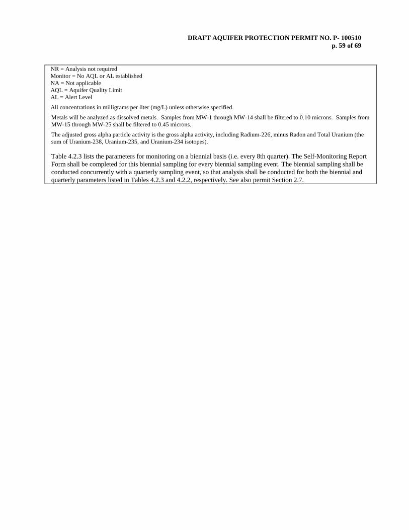
DRAFT AQUIFER PROTECTION PERMIT NO. P- 100510 p. 59 of 69
NR = Analysis not required Monitor = No AQL or AL established NA = Not applicable AQL = Aquifer Quality Limit AL = Alert Level
All concentrations in milligrams per liter (mg/L) unless otherwise specified.
Metals will be analyzed as dissolved metals. Samples from MW-1 through MW-14 shall be filtered to 0.10 microns. Samples from MW-15 through MW-25 shall be filtered to 0.45 microns.
The adjusted gross alpha particle activity is the gross alpha activity, including Radium-226, minus Radon and Total Uranium (the sum of Uranium-238, Uranium-235, and Uranium-234 isotopes). Table 4.2.3 lists the parameters for monitoring on a biennial basis (i.e. every 8th quarter). The Self-Monitoring Report Form shall be completed for this biennial sampling for every biennial sampling event. The biennial sampling shall be conducted concurrently with a quarterly sampling event, so that analysis shall be conducted for both the biennial and quarterly parameters listed in Tables 4.2.3 and 4.2.2, respectively. See also permit Section 2.7.

DRAFT AQUIFER PROTECTION PERMIT NO. P- 100510 p. 60 of 69
TABLE 4.2.3 BIENNIAL COMPLIANCE GROUNDWATER MONITORING REQUIREMENTS
PARAMETER MW-11R AQL AL MW-12
AQL AL MW-14 AQL AL
Total Alkalinity Monitor Monitor Monitor Monitor Monitor Monitor Carbonate Monitor Monitor Monitor Monitor Monitor Monitor Bicarbonate Monitor Monitor Monitor Monitor Monitor Monitor Hydroxide Monitor Monitor Monitor Monitor Monitor Monitor Chloride Monitor Monitor Monitor Monitor Monitor Monitor Sodium Monitor Monitor Monitor Monitor Monitor Monitor Potassium Monitor Monitor Monitor Monitor Monitor Monitor Calcium Monitor Monitor Monitor Monitor Monitor Monitor Aluminum Monitor Monitor Monitor Monitor Monitor Monitor Antimony 0.009 Monitor 0.006 0.0048 0.006 0.0048 Arsenic 0.05 0.04 0.05 0.04 0.05 0.04 Barium 2.0 1.6 2.0 1.6 2.0 1.6 Chromium 0.1 0.08 0.1 0.08 0.1 0.08 Iron Monitor Monitor Monitor Monitor Monitor Monitor Lead 0.05 0.04 0.05 0.04 0.05 0.04 Thallium NR NR NR NR NR NR Cobalt Monitor Monitor Monitor Monitor Monitor Monitor Manganese Monitor Monitor Monitor Monitor Monitor Monitor Zinc Monitor Monitor Monitor Monitor Monitor Monitor Adjusted Gross Alpha Particle Activity (pCi/L) 22.3 Monitor 15 14.1 154 Monitor
Radium-226 + Radium-228 (pCi/L) 5.0 4.0 5.0 4.0 5.0 4.0
Total Uranium Monitor Monitor Monitor Monitor Monitor Monitor Benzene 0.005 Monitor 0.005 Monitor 0.005 Monitor Toluene 1.0 Monitor 1.0 Monitor 1.0 Monitor Ethylbenzene 0.7 Monitor 0.7 Monitor 0.7 Monitor Total Xylenes 10.0 Monitor 10.0 Monitor 10.0 Monitor

DRAFT AQUIFER PROTECTION PERMIT NO. P- 100510 p. 61 of 69
NR = Analysis not required Monitor = No AQL or AL established AQL = Aquifer Quality Limit AL = Alert Level
All concentrations in milligrams per liter (mg/L) unless otherwise specified.
Metals will be analyzed as dissolved metals. Samples from MW-1 through MW-14 shall be filtered to 0.10 microns. Samples from MW-15 through MW-25 shall be filtered to 0.45 microns.
The adjusted gross alpha particle activity is the gross alpha activity, including Radium-226, minus Radon and Total Uranium (the sum of Uranium-238, Uranium-235, and Uranium-234 isotopes). Table 4.2.3 lists the parameters for monitoring on a biennial basis (i.e. every 8th quarter). The Self-Monitoring Report Form shall be completed for this biennial sampling for every biennial sampling event. The biennial sampling shall be conducted concurrently with a quarterly sampling event, so that analysis shall be conducted for both the biennial and quarterly parameters listed in Tables 4.2.3 and 4.2.2, respectively. See also permit Section 2.7.
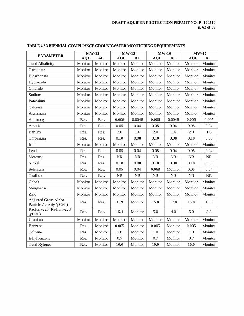
DRAFT AQUIFER PROTECTION PERMIT NO. P- 100510 p. 62 of 69
TABLE 4.2.3 BIENNIAL COMPLIANCE GROUNDWATER MONITORING REQUIREMENTS
PARAMETER MW-13 AQL AL
MW-15 AQL AL
MW-16 AQL AL
MW-17 AQL AL
Total Alkalinity Monitor Monitor Monitor Monitor Monitor Monitor Monitor Monitor Carbonate Monitor Monitor Monitor Monitor Monitor Monitor Monitor Monitor Bicarbonate Monitor Monitor Monitor Monitor Monitor Monitor Monitor Monitor Hydroxide Monitor Monitor Monitor Monitor Monitor Monitor Monitor Monitor Chloride Monitor Monitor Monitor Monitor Monitor Monitor Monitor Monitor Sodium Monitor Monitor Monitor Monitor Monitor Monitor Monitor Monitor Potassium Monitor Monitor Monitor Monitor Monitor Monitor Monitor Monitor Calcium Monitor Monitor Monitor Monitor Monitor Monitor Monitor Monitor Aluminum Monitor Monitor Monitor Monitor Monitor Monitor Monitor Monitor Antimony Res. Res. 0.006 0.0048 0.006 0.0048 0.006 0.005 Arsenic Res. Res. 0.05 0.04 0.05 0.04 0.05 0.04 Barium Res. Res. 2.0 1.6 2.0 1.6 2.0 1.6 Chromium Res. Res. 0.10 0.08 0.10 0.08 0.10 0.08 Iron Monitor Monitor Monitor Monitor Monitor Monitor Monitor Monitor Lead Res. Res. 0.05 0.04 0.05 0.04 0.05 0.04 Mercury Res. Res. NR NR NR NR NR NR Nickel Res. Res. 0.10 0.08 0.10 0.08 0.10 0.08 Selenium Res. Res. 0.05 0.04 0.068 Monitor 0.05 0.04 Thallium Res. Res. NR NR NR NR NR NR Cobalt Monitor Monitor Monitor Monitor Monitor Monitor Monitor Monitor Manganese Monitor Monitor Monitor Monitor Monitor Monitor Monitor Monitor Zinc Monitor Monitor Monitor Monitor Monitor Monitor Monitor Monitor Adjusted Gross Alpha Particle Activity (pCi/L) Res. Res. 31.9 Monitor 15.0 12.0 15.0 13.3
Radium-226+Radium-228 (pCi/L) Res. Res. 15.4 Monitor 5.0 4.0 5.0 3.8
Uranium Monitor Monitor Monitor Monitor Monitor Monitor Monitor Monitor Benzene Res. Monitor 0.005 Monitor 0.005 Monitor 0.005 Monitor Toluene Res. Monitor 1.0 Monitor 1.0 Monitor 1.0 Monitor Ethylbenzene Res. Monitor 0.7 Monitor 0.7 Monitor 0.7 Monitor Total Xylenes Res. Monitor 10.0 Monitor 10.0 Monitor 10.0 Monitor
DRAFT AQUIFER PROTECTION PERMIT NO. P- 100510 p. 63 of 69
Res. = Reserved. This pertains to installation of MW-13, which is contingent on resuming construction of Tailings Dam No. 3 (see Compliance Schedule Item No. 4). At the conclusion of eight (8) rounds of quarterly groundwater sampling, the permittee is required to submit an Ambient Groundwater Monitoring Report and permit amendment request to ADEQ to propose ALs and AQLs based on ambient data. The permit will be amended at the conclusion of Ambient Groundwater Monitoring to establish reserved values.
Monitor = No AQL or AL established AQL = Aquifer Quality Limit AL = Alert Level
All concentrations in milligrams per liter (mg/L) unless otherwise specified.
Metals will be analyzed as dissolved metals. Samples from MW-1 through MW-14 shall be filtered to 0.10 microns. Samples from MW-15 through MW-25 shall be filtered to 0.45 microns.
The adjusted gross alpha particle activity is the gross alpha activity, including Radium-226, minus Radon and Total Uranium (the sum of Uranium-238, Uranium-235, and Uranium-234 isotopes). Table 4.2.3 lists the parameters for monitoring on a biennial basis (i.e. every 8th quarter). The Self-Monitoring Report Form shall be completed for this biennial sampling for every biennial sampling event. The biennial sampling shall be conducted concurrently with a quarterly sampling event, so that analysis shall be conducted for both the biennial and quarterly parameters listed in Tables 4.2.3 and 4.2.2, respectively. See also permit Section 2.7.
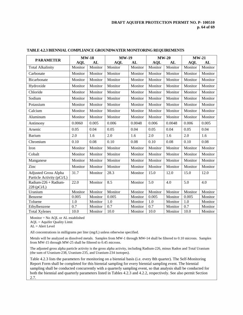
DRAFT AQUIFER PROTECTION PERMIT NO. P- 100510 p. 64 of 69
TABLE 4.2.3 BIENNIAL COMPLIANCE GROUNDWATER MONITORING REQUIREMENTS
PARAMETER MW-18 AQL AL
MW-19 AQL AL
MW-20 AQL AL
MW-21 AQL AL
Total Alkalinity Monitor Monitor Monitor Monitor Monitor Monitor Monitor Monitor Carbonate Monitor Monitor Monitor Monitor Monitor Monitor Monitor Monitor Bicarbonate Monitor Monitor Monitor Monitor Monitor Monitor Monitor Monitor Hydroxide Monitor Monitor Monitor Monitor Monitor Monitor Monitor Monitor Chloride Monitor Monitor Monitor Monitor Monitor Monitor Monitor Monitor Sodium Monitor Monitor Monitor Monitor Monitor Monitor Monitor Monitor Potassium Monitor Monitor Monitor Monitor Monitor Monitor Monitor Monitor Calcium Monitor Monitor Monitor Monitor Monitor Monitor Monitor Monitor Aluminum Monitor Monitor Monitor Monitor Monitor Monitor Monitor Monitor Antimony 0.0060 0.005 0.006 0.0048 0.006 0.0048 0.006 0.005 Arsenic 0.05 0.04 0.05 0.04 0.05 0.04 0.05 0.04 Barium 2.0 1.6 2.0 1.6 2.0 1.6 2.0 1.6 Chromium 0.10 0.08 0.10 0.08 0.10 0.08 0.10 0.08 Iron Monitor Monitor Monitor Monitor Monitor Monitor Monitor Monitor Cobalt Monitor Monitor Monitor Monitor Monitor Monitor Monitor Monitor Manganese Monitor Monitor Monitor Monitor Monitor Monitor Monitor Monitor Zinc Monitor Monitor Monitor Monitor Monitor Monitor Monitor Monitor Adjusted Gross Alpha Particle Activity (pCi/L)
31.7 Monitor 28.3 Monitor 15.0 12.0 15.0 12.0
Radium-226 + Radium-228 (pCi/L)
22.0 Monitor 8.5 Monitor 5.0 4.0 5.0 4.0
Uranium Monitor Monitor Monitor Monitor Monitor Monitor Monitor Monitor Benzene 0.005 Monitor 0.005 Monitor 0.005 Monitor 0.005 Monitor Toluene 1.0 Monitor 1.0 Monitor 1.0 Monitor 1.0 Monitor Ethylbenzene 0.7 Monitor 0.7 Monitor 0.7 Monitor 0.7 Monitor Total Xylenes 10.0 Monitor 10.0 Monitor 10.0 Monitor 10.0 Monitor
Monitor = No AQL or AL established AQL = Aquifer Quality Limit AL = Alert Level
All concentrations in milligrams per liter (mg/L) unless otherwise specified.
Metals will be analyzed as dissolved metals. Samples from MW-1 through MW-14 shall be filtered to 0.10 microns. Samples from MW-15 through MW-25 shall be filtered to 0.45 microns.
The adjusted gross alpha particle activity is the gross alpha activity, including Radium-226, minus Radon and Total Uranium (the sum of Uranium-238, Uranium-235, and Uranium-234 isotopes).
Table 4.2.3 lists the parameters for monitoring on a biennial basis (i.e. every 8th quarter). The Self-Monitoring Report Form shall be completed for this biennial sampling for every biennial sampling event. The biennial sampling shall be conducted concurrently with a quarterly sampling event, so that analysis shall be conducted for both the biennial and quarterly parameters listed in Tables 4.2.3 and 4.2.2, respectively. See also permit Section 2.7.

DRAFT AQUIFER PROTECTION PERMIT NO. P- 100510 p. 65 of 69
TABLE 4.2.3 BIENNIAL COMPLIANCE GROUNDWATER MONITORING REQUIREMENTS
PARAMETER MW-22 AQL AL
MW-23 AQL AL
MW-24 AQL AL
MW-25 AQL AL
Total Alkalinity Monitor Monitor Monitor Monitor Monitor Monitor Monitor Monitor Carbonate Monitor Monitor Monitor Monitor Monitor Monitor Monitor Monitor Bicarbonate Monitor Monitor Monitor Monitor Monitor Monitor Monitor Monitor Hydroxide Monitor Monitor Monitor Monitor Monitor Monitor Monitor Monitor Chloride Monitor Monitor Monitor Monitor Monitor Monitor Monitor Monitor Sodium Monitor Monitor Monitor Monitor Monitor Monitor Monitor Monitor Potassium Monitor Monitor Monitor Monitor Monitor Monitor Monitor Monitor Calcium Monitor Monitor Monitor Monitor Monitor Monitor Monitor Monitor Aluminum Monitor Monitor Monitor Monitor Monitor Monitor Monitor Monitor Antimony 0.0060 0.0048 Res. Res. 0.006 0.0048 0.006 0.0048 Arsenic 0.05 0.04 Res. Res. 0.05 0.04 0.05 0.04 Barium 2.0 1.6 Res. Res. 2.0 1.6 2.0 1.6 Chromium 0.10 0.08 Res. Res. 0.10 0.08 0.10 0.08 Iron Monitor Monitor Monitor Monitor Monitor Monitor Monitor Monitor Mercury NR NR Res. Res. NR NR NR NR Thallium NR NR Res. Res. NR NR NR NR Cobalt Monitor Monitor Monitor Monitor Monitor Monitor Monitor Monitor Manganese Monitor Monitor Monitor Monitor Monitor Monitor Monitor Monitor Zinc Monitor Monitor Monitor Monitor Monitor Monitor Monitor Monitor Adjusted Gross Alpha Particle Activity (pCi/L)
15.0 12.0 Res. Res. 15.0 12.0 15.0 12.0
Radium-226 + Radium-228 (pCi/L)
5.0 4.0 Res. Res. 5.0 4.0 7.0 Monitor
Uranium Monitor Monitor Monitor Monitor Monitor Monitor Monitor Monitor Benzene 0.005 Monitor 0.005 Monitor 0.005 Monitor 0.005 0.004 Toluene 1.0 Monitor 1.0 Monitor 1.0 Monitor 1.0 0.8 Ethylbenzene 0.7 Monitor 0.7 Monitor 0.7 Monitor 0.7 0.56 Total Xylenes 10.0 Monitor 10.0 Monitor 10.0 Monitor 10.0 8.0 Free Cyanide NR NR Res. Res. NR NR NR NR
DRAFT AQUIFER PROTECTION PERMIT NO. P- 100510 p. 66 of 69
Res. = Reserved. This pertains toMW-23 and MW-25. At the conclusion of eight (8) rounds of quarterly groundwater sampling, the permittee is required to submit an Ambient Groundwater Monitoring Report and permit amendment request to ADEQ to propose ALs and AQLs based on ambient data. The permit will be amended at the conclusion of Ambient Groundwater Monitoring to establish reserved values.
Monitor = No AQL or AL established AQL = Aquifer Quality Limit AL = Alert Level
All concentrations in milligrams per liter (mg/L) unless otherwise specified.
Metals will be analyzed as dissolved metals. Samples from MW-1 through MW-14 shall be filtered to 0.10 microns. Samples from MW-15 through MW-25 shall be filtered to 0.45 microns.
The adjusted gross alpha particle activity is the gross alpha activity, including Radium-226, minus Radon and Total Uranium (the sum of Uranium-238, Uranium-235, and Uranium-234 isotopes).
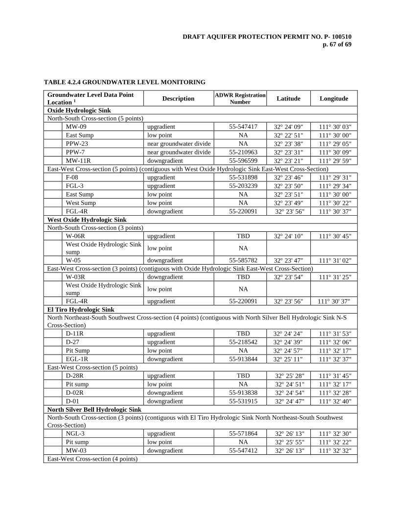
DRAFT AQUIFER PROTECTION PERMIT NO. P- 100510 p. 67 of 69
TABLE 4.2.4 GROUNDWATER LEVEL MONITORING
Groundwater Level Data Point Location 1 Description ADWR Registration
Number Latitude Longitude
Oxide Hydrologic Sink North-South Cross-section (5 points) MW-09 upgradient 55-547417 32° 24' 09" 111° 30' 03" East Sump low point NA 32° 22' 51" 111° 30' 00" PPW-23 near groundwater divide NA 32° 23' 38" 111° 29' 05" PPW-7 near groundwater divide 55-210963 32° 23' 31" 111° 30' 09" MW-11R downgradient 55-596599 32° 23' 21" 111° 29' 59" East-West Cross-section (5 points) (contiguous with West Oxide Hydrologic Sink East-West Cross-Section) F-08 upgradient 55-531898 32° 23' 46" 111° 29' 31" FGL-3 upgradient 55-203239 32° 23' 50" 111° 29' 34" East Sump low point NA 32° 23' 51" 111° 30' 00" West Sump low point NA 32° 23' 49" 111° 30' 22" FGL-4R downgradient 55-220091 32° 23' 56" 111° 30' 37" West Oxide Hydrologic Sink North-South Cross-section (3 points) W-06R upgradient TBD 32° 24' 10" 111° 30' 45"
West Oxide Hydrologic Sink sump low point NA
W-05 downgradient 55-585782 32° 23' 47" 111° 31' 02" East-West Cross-section (3 points) (contiguous with Oxide Hydrologic Sink East-West Cross-Section) W-03R downgradient TBD 32° 23' 54" 111° 31' 25"
West Oxide Hydrologic Sink sump low point NA
FGL-4R upgradient 55-220091 32° 23' 56" 111° 30' 37" El Tiro Hydrologic Sink North Northeast-South Southwest Cross-section (4 points) (contiguous with North Silver Bell Hydrologic Sink N-S Cross-Section) D-11R upgradient TBD 32° 24' 24" 111° 31' 53" D-27 upgradient 55-218542 32° 24' 39" 111° 32' 06" Pit Sump low point NA 32° 24' 57" 111° 32' 17" EGL-1R downgradient 55-913844 32° 25' 11" 111° 32' 37" East-West Cross-section (5 points) D-28R upgradient TBD 32° 25' 28" 111° 31' 45" Pit sump low point NA 32° 24' 51" 111° 32' 17" D-02R downgradient 55-913838 32° 24' 54" 111° 32' 28" D-01 downgradient 55-531915 32° 24' 47" 111° 32' 40" North Silver Bell Hydrologic Sink North-South Cross-section (3 points) (contiguous with El Tiro Hydrologic Sink North Northeast-South Southwest Cross-Section) NGL-3 upgradient 55-571864 32° 26' 13" 111° 32' 30" Pit sump low point NA 32° 25' 55" 111° 32' 22" MW-03 downgradient 55-547412 32° 26' 13" 111° 32' 32" East-West Cross-section (4 points)

DRAFT AQUIFER PROTECTION PERMIT NO. P- 100510 p. 68 of 69
MW-02 downgradient 55-547411 32° 26' 00" 111° 32' 51" Pit Sump low point NA 32° 25' 55" 111° 32' 22" B-18 upgradient 55-216121 32° 25' 42" 111° 32' 18" 5.0 REFERENCES AND PERTINENT INFORMATION
The terms and conditions set forth in this permit have been developed based upon the information contained in the following, which are on file with the Department:
1. Application submitted November 30, 2016 and subsequent additional information.
6.0 NOTIFICATION PROVISIONS
6.1 Annual Registration Fees The permittee is notified of the obligation to pay an Annual Registration Fee to ADEQ. The Annual Registration Fee is based upon the amount of daily influent or discharge of pollutants in gallons per day as established by A.R.S. § 49-242.
6.2 Duty to Comply [A.R.S. §§ 49-221 through 49-263] The permittee is notified of the obligation to comply with all conditions of this permit and all applicable provisions of Title 49, Chapter 2, Articles 1, 2 and 3 of the Arizona Revised Statutes, Title 18, Chapter 9, Articles 1 through 4, and Title 18, Chapter 11, Article 4 of the Arizona Administrative Code. Any permit non-compliance constitutes a violation and is grounds for an enforcement action pursuant to Title 49, Chapter 2, Article 4 or permit amendment, suspension, or revocation.
6.3 Duty to Provide Information [A.R.S. §§ 49-243(K)(2) and 49-243(K)(8)] The permittee shall furnish to the Director, or an authorized representative, within a time specified, any information which the Director may request to determine whether cause exists for amending or terminating this permit, or to determine compliance with this permit. The permittee shall also furnish to the Director, upon request, copies of records required to be kept by this permit.
6.4 Compliance with Aquifer Water Quality Standards [A.R.S. §§ 49-243(B)(2) and 49-243(B)(3)] The permittee shall not cause or contribute to a violation of an aquifer water quality standard at the applicable point of compliance for the facility. Where, at the time of issuance of the permit, an aquifer already exceeds an aquifer water quality standard for a pollutant, the permittee shall not discharge that pollutant so as to further degrade, at the applicable point of compliance for the facility, the water quality of any aquifer for that pollutant.
6.5 Technical and Financial Capability [A.R.S. §§ 49-243(K)(8) and 49-243(N) and A.A.C. R18-9-A202(B) and R18-9-A203(E) and (F)] The permittee shall have and maintain the technical and financial capability necessary to fully carry out the terms and conditions of this permit. Any bond, insurance policy, trust fund, or other financial assurance mechanism provided as a demonstration of financial capability in the permit application, pursuant to A.A.C. R18-9-A203(D), shall be in effect prior to any discharge authorized by this permit and shall remain in effect for the duration of the permit.
6.6 Reporting of Bankruptcy or Environmental Enforcement [A.A.C. R18-9-A207(C)] The permittee shall notify the Director within five days after the occurrence of any one of the following: 1. The filing of bankruptcy by the permittee. 2. The entry of any order or judgment not issued by the Director against the permittee for the enforcement
of any environmental protection statute or rule. 6.7 Monitoring and Records [A.R.S. § 49-243(K)(8) and A.A.C. R18-9-A206]
DRAFT AQUIFER PROTECTION PERMIT NO. P- 100510 p. 69 of 69
The permittee shall conduct any monitoring activity necessary to assure compliance with this permit, with the applicable water quality standards established pursuant to A.R.S. §§ 49-221 and 49-223 and §§ 49-241 through 49-252.
6.8 Inspection and Entry [A.R.S. §§ 41-1009, 49-203(B) and 49-243(K)(8)]
In accordance with A.R.S. §§ 41-1009 and 49-203(B), the permittee shall allow the Director, or an authorized representative, upon the presentation of credentials and other documents as may be required by law, to enter and inspect the facility as reasonably necessary to ensure compliance with Title 49, Chapter 2, Article 3 of the Arizona Revised Statutes, and Title 18, Chapter 9, Articles 1 through 4 of the Arizona Administrative Code and the terms and conditions of this permit.
6.9 Duty to Modify [A.R.S. § 49-243(K)(8) and A.A.C. R18-9-A211] The permittee shall apply for and receive a written amendment before deviating from any of the designs or operational practices specified by this permit.
6.10 Permit Action: Amendment, Transfer, Suspension and Revocation
[A.R.S. §§ 49-201, 49-241 through 251, A.A.C. R18-9-A211, R18-9-A212 and R18-9-A213] This permit may be amended, transferred, renewed, or revoked for cause, under the rules of the Department. The permittee shall notify the Groundwater Section in writing within 15 days after any change in the owner or operator of the facility. The notification shall state the permit number, the name of the facility, the date of property transfer, and the name, address, and phone number where the new owner or operator can be reached. The operator shall advise the new owner or operators of the terms of this permit and the need for permit transfer in accordance with the rules.
7.0 ADDITIONAL PERMIT CONDITIONS
7.1 Other Information [A.R.S. § 49-243(K)(8)]
Where the permittee becomes aware that it failed to submit any relevant facts in a permit application, or submitted incorrect information in a permit application or in any report to the Director, the permittee shall promptly submit the correct facts or information.
7.2 Severability
[A.R.S. §§ 49-201, 49-241 through 251, A.A.C. R18-9-A211, R18-9-A212 and R18-9-A213] The provisions of this permit are severable, and if any provision of this permit, or the application of any provision of this permit to any circumstance, is held invalid, the application of such provision to other circumstances, and the remainder of this permit, shall not be affected thereby. The filing of a request by the permittee for a permit action does not stay or suspend the effectiveness of any existing permit condition.
7.3 Permit Transfer
This permit may not be transferred to any other person except after notice to and approval of the transfer by the Department. No transfer shall be approved until the applicant complies with all transfer requirements as specified in A.A.C. R18-9-A212(B) and (C).