State highway construction and maintenance noise and ... · State highway construction and...
104
State highway construction and maintenance noise and vibration guide The NZTA recognises that noise and vibration associated with road construction and maintenance can be intrusive and disturbing, especially at night. The effective management of such noise and vibration is essential to avoid unreasonable effects on communities and individuals. This guide has been produced to inform NZTA staff, contractors and the public about construction and maintenance noise and vibration. Information is also provided on prediction, management, mitigation and documentation of such noise and vibration. August 2013 / Version 1.0
Transcript of State highway construction and maintenance noise and ... · State highway construction and...

State highway construction and maintenance noise and vibration guide The NZTA recognises that noise and vibration associated with road construction and maintenance can be intrusive and disturbing, especially at night. The effective management of such noise and vibration is essential to avoid unreasonable effects on communities and individuals. This guide has been produced to inform NZTA staff, contractors and the public about construction and maintenance noise and vibration. Information is also provided on prediction, management, mitigation and documentation of such noise and vibration.
August 2013 / Version 1.0

State highway construction and maintenance noise and vibration guide Version 1.0NZ Transport Agency August 2013
ISBN 978-0-478-38065-1 (online) ISBN 978-0-478-38066-8 (print) Copyright: August 2013 NZ Transport Agency
National Office 50 Victoria Street Private Bag 6995 Wellington 6141 New Zealand
T 64 4 894 5400 F 64 4 894 6100
© Copyright Standards New Zealand 2011. Content from ‘NZS 6803:1999 Acoustics – Construction noise’ has been reproduced with permission from Standards New Zealand under Copyright Licence 000894.
Permission to reproduce extracts from ‘BS 5228-1:2009 Code of practice for noise and vibration control on construction and open sites – Noise’ and ‘BS 5228-2:2009 Code of practice for noise and vibration control on construction and open sites – Vibration’ granted by the British Standards Institution. © BSI (www.bsigroup.com). All rights reserved.

Contents1 Introduction
1.1 Background 2
1.2 Purpose of this document 3
1.3 Responsibilities 6
1.4 Tools 8
1.5 Noise fundamentals 10
1.6 Vibration fundamentals 12
2 Criteria and legislation2.1 Noise 18
2.2 Vibration 21
2.3 Ground borne noise 24
2.4 Summary 25
2.5 Best practicable option 26
2.6 Designation conditions 26
3 NZTA processes3.1 Construction project stages 32
3.2 Maintenance stages 33
3.3 Scope of works 33
3.4 Tier 1 – Risk assessment - 34 construction
3.5 Tier 2 – Screening assessment - construction and maintenance 35
3.6 Tier 3 – Assessment 36
3.7 Reporting 38
4 Predictions4.1 Noise calculation 42
4.2 Noise data 49
4.3 Web noise calculator 52
4.4 Noise modeling 55
4.5 Vibration calculation 56
4.6 Vibration data 68
5 Management5.1 Plans and schedules 72
5.2 Communications 73
5.3 Mitigation 74
5.4 Training 78
5.5 Condition surveys 78
5.6 Night works 79
5.7 Diversions 80
5.8 Complaints 82
5.9 Monitoring 84
5.10 Documentation 87
Glossary and references Glossary 94
References 98


1.1 Background 2
1.2 Purpose of this document 3
Case study – Victoria Park Tunnel 4
1.3 Responsibilities 6
Other guidance 7
1.4 Tools 8
1.5 Noise fundamentals 10
1.6 Vibration fundamentals 12
1 Introduction
1

2 NZ Transport Agency | State highway construction and maintenance noise and vibration guide | SP/M/023 | August 2013 / version 1.0
1.1 Background
The NZ Transport Agency (NZTA) aims to be a good neighbour, taking social and environmental responsibility seriously, including the management of construction and maintenance noise and vibration. This is reflected in external and internal NZTA strategy and policy documents. These documents are consistent with the requirements of the Resource Management Act 199101 (RMA) and the Land Transport Management Act 200302 (LTMA).
FIGURe 1.1 Relationship of this guide to key NZTA policy & strategy documents
State highway construction and maintenance noise and vibration guide
Statement of Intent04 2012–2015
New Zealand Standard 6803:1999 Acoustics – Construction noise06
State Highway environmental Plan05
Government Policy Statement03
2012/13 – 2012/22
The NZTA’s [State Highway] Environmental plan05 sets a formal objective regarding noise and vibration from construction and maintenance of the state highway network:
N3 Manage construction and maintenance noise to acceptable levels.
V3 Avoid or reduce, as far as is practicable, the disturbance to communities from vibration during construction and maintenance.
Construction noise and vibration are associated with works to build new or upgrade existing state highways, while maintenance noise and vibration are associated with works to maintain the standard of, or repair, existing state highways. Similar types of equipment and techniques are employed to undertake construction and maintenance works and hence this guide applies to both.
Whilst construction and maintenance noise and vibration issues are often most critical on urban motorways, this guide applies to works on all state highways. The majority of the advice contained in this guide could also be applied to construction and maintenance works by territorial authorities on other roads. Similarly, much of the information may also be of assistance for construction works of any kind, including industrial and commercial developments and other infrastructure such as rail.
This guide provides a range of material: some basic, some technical and some specific to the NZTA. The main focus of the guide is to assist project and environmental managers.
01 New Zealand Legislation (1991) Resource Management Act. www.legislation.govt.nz
02 Ministry of the Environment (2003) Land Transport Management Act. www.mfe.govt.nz
03 New Zealand Government (2011) Government policy statement on land transport funding 2012/13-2021/22. www.transport.govt.nz
04 NZ Transport Agency (2011) Statement of intent 2012-2015. www.nzta.govt.nz
05 Transit New Zealand (2008) Environment plan, Version 2. www.nzta.govt.nz
06 Standards New Zealand (1999) NZS 6803:1999 Acoustics – Construction noise. www.standards.co.nz
Resource Managem
ent Act 1991La
nd Tr
ansp
ort M
anag
emen
t Act
2003
NZ Transport Agency | State highway construction and maintenance noise and vibration guide | SP/M/023 | August 2013 / version 1.0 3
1.2 Purpose of this document
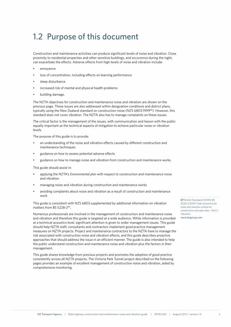
Construction and maintenance activities can produce significant levels of noise and vibration. Close proximity to residential properties and other sensitive buildings, and occurrence during the night, can exacerbate the effects. Adverse effects from high levels of noise and vibration include:
• annoyance
• loss of concentration, including effects on learning performance
• sleep disturbance
• increased risk of mental and physical health problems
• building damage.
The NZTA objectives for construction and maintenance noise and vibration are shown on the previous page. These issues are also addressed within designation conditions and district plans, typically using the New Zealand standard on construction noise (NZS 6803:199906). However, this standard does not cover vibration. The NZTA also has to manage complaints on these issues.
The critical factor is the management of the issues, with communication and liaison with the public equally important as the technical aspects of mitigation to achieve particular noise or vibration levels.
The purpose of this guide is to provide:
• an understanding of the noise and vibration effects caused by different construction and maintenance techniques
• guidance on how to assess potential adverse effects
• guidance on how to manage noise and vibration from construction and maintenance works.
This guide should assist in:
• applying the NZTA’s Environmental plan with respect to construction and maintenance noise and vibration
• managing noise and vibration during construction and maintenance works
• avoiding complaints about noise and vibration as a result of construction and maintenance work.
This guide is consistent with NZS 6803 supplemented by additional information on vibration matters from BS 5228-207.
Numerous professionals are involved in the management of construction and maintenance noise and vibration and therefore this guide is targeted at a wide audience. While information is provided at a technical acoustics level, significant attention is given to wider management issues. This guide should help NZTA staff, consultants and contractors implement good practice management measures on NZTA projects. Project and maintenance contractors to the NZTA have to manage the risk associated with construction noise and vibration effects, and this guide describes proactive approaches that should address the issue in an efficient manner. The guide is also intended to help the public understand construction and maintenance noise and vibration plus the factors in their management.
This guide shares knowledge from previous projects and promotes the adoption of good practice consistently across all NZTA projects. The Victoria Park Tunnel project described on the following pages provides an example of excellent management of construction noise and vibration, aided by comprehensive monitoring.
07 British Standard (2009) BS 5228-2:2009 Code of practice for noise and vibration control on construction and open sites - Part 2: Vibration. www.bsigroup.com

4 NZ Transport Agency | State highway construction and maintenance noise and vibration guide | SP/M/023 | August 2013 / version 1.0
Case study – Victoria Park Tunnel, Auckland (2009–2011)The Victoria Park Tunnel (VPT) project upgraded 2.2km of State Highway 1, from the Auckland Harbour Bridge to the Wellington Street motorway overbridge, and removed the last remaining bottleneck on the central Auckland motorway system. It comprises a 450m cut and cover tunnel under Victoria Park for three northbound traffic lanes, widening the motorway through St Mary’s Bay by one lane in each direction, and refurbishing the Victoria Park viaduct to carry four southbound traffic lanes. The project is being delivered by the Victoria Park Alliance comprising the NZTA, Fletcher Construction, Beca, Higgins and Parsons Brinckerhoff.
According to Project Manager Andrew Rose from the Alliance, ‘As a major infrastructure project with numerous neighbouring residents (some as close as 5m) and with works occurring at weekends and at night, the management of construction noise and vibration was always at the top of the project agenda.’
The project team responded with exemplary management practices, approaching all issues proactively and communicating effectively with neighbours. Examples of good practice on the VPT project include:
• The stakeholder manager provided a single point of contact and responsibility for all issues, and advocated for the community issues on the project management team.
• Consistent and clear communications were given to the community and residents. Signage was erected and updated around the construction site explaining the programme, progress and methods of construction. Flyers were regularly sent out to residents giving construction updates, which included reasons for and dates of future night-time and weekend works.
• Complimentary event tickets were offered to residents during particularly noisy periods of works.
• Works were scheduled in consultation with residents as to whether they preferred Sunday or night works, for example.
• Alternatives to tonal reversing alarms were required on all vehicles operating at night (broadband directional reversing alarms were bulk-purchased by the project).
• Noise measurements were undertaken on significant noise sources before they started operation.
• Site Specific Construction Noise Management Plans were prepared for all activities predicted to be above the project noise criteria.
• Regular site noise monitoring of construction activities was carried out to confirm compliance with noise criteria.
• Prior to any night works, the teams were briefed on the behaviours expected of them to minimise all unnecessary noise.
• Project-wide planning ensured noise-intensive activities were undertaken over the same period to minimise the duration of disturbance on residents.
• Complaints were actively investigated and residents kept informed of outcomes.
• The Auckland Council (formerly Auckland City Council) Noise Officer was in close liaison with the project from the start.
• Ongoing feedback was provided to the construction teams on their performance.
• Project key performance indicators were compiled monthly and circulated to alliance board members, as well as within the project team. One of the indicators related specifically to noise, where a comparison was made between night works and the number of complaints.
FIGURe 1.2 Victoria Park Tunnel project
Victoria ParkSt Mary’s BayAuckland Harbour Bridge
Wellington Street

NZ Transport Agency | State highway construction and maintenance noise and vibration guide | SP/M/023 | August 2013 / version 1.0 5
MANAGeMeNT PLANS
A procedure was set up within the Construction Noise and Vibration Management Plan (section 5.10) to demonstrate compliance with project noise criteria to Auckland Council and, in situations where these could not be met, prove that additional noise mitigation measures were being implemented. Using the construction noise calculator on the NZTA Transport Noise website (section 4.3), noise predictions were undertaken for any construction activity that had the potential to breach the project noise criteria. A Site Specific Construction Noise Management Plan (SSCNMP) was submitted to the council for activities above the noise criteria. These plans used the NZTA’s Noise Management Schedules as a template (section 5.10). Amongst other things, the SSCNMP contained the mitigation measures proposed, such as the use of temporary noise barriers, localised screening of machinery and smaller plant. Works would not commence until the council approved the SSCNMP.
The SSCNMP procedure developed at VPT ensured responsibility for construction noise management was shared by all of the project team. Prior to any night works being undertaken, the engineer overseeing the works submitted a noise request to the environment manager for review. This ensured that the engineers were considering construction noise impacts when planning night works. Noise predictions were then undertaken based on the information provided within the noise request and, if required, an SSCNMP was submitted to the council for approval. Each approved noise request was subject to a number of conditions which specified the equipment to be used, hours of work and mitigation measures.
In the first months of the project, an SSCNMP was submitted to the council for approval whenever the predicted levels were above the project noise criteria. Once it was clear to the council that the project team was committed to noise management and the implementation of mitigation measures, this requirement was relaxed. Subsequently, an SSCNMP was only submitted to the council when the predicted levels were 10dB or more above the noise criteria.
Over 100 SSCNMPs were submitted to Auckland Council, and over a 100 more situations were modelled by the project team using the NZTA online calculator to be below the threshold for submission of an SSCNMP.
The preferred terminology for an SSCNMP is now a Construction Noise and Vibration Management Schedule (CNVMS).
FIGURe 1.4 Temporary noise barriers in use at Victoria Park Tunnel
FIGURe 1.3 Community and resident communications

6 NZ Transport Agency | State highway construction and maintenance noise and vibration guide | SP/M/023 | August 2013 / version 1.0
1.3 Responsibilities
ConstructionResponsibility for construction noise changes throughout a project’s life. Figure 1.5 illustrates some of the key stages. During the planning stage, an acoustics specialist advises the planner of the appropriate noise and vibration criteria, identifies the nearest sensitive neighbouring activities, predicts the construction noise levels and investigates appropriate mitigation, if required. In simple cases, such as where there are no nearby neighbours, this work is not required. The project engineer or construction advisor would supply the indicative construction methodology.
As the construction methodology is confirmed in the design stage, a further assessment of the noise and vibration implications may be required to reassess the impacts and to prepare suitable management plans. In a design and construct contract, the acoustics specialist and environment manager will both be in the contractor’s team.
Outside of design and construct contracts, the roles may be filled by personnel from a number of different organisations. The environment manager should always be part of the contractor’s team. Acoustics advice may also be required during the build stage to finalise the noise and vibration predictions and mitigation. Because of the workload on larger projects, the environment manager is unlikely to have sufficient time to be proactive on these issues and therefore may require assistance in the form of a dedicated person with the appropriate knowledge and responsibilities.
MaintenanceResponsibility during operation and maintenance lies with the maintenance contractor’s environmental manager, followed by team leaders for individual works.
STAGe ReSPONSIBILITy
INV
eSTI
GAT
ION
DeS
IGN
CON
STRU
CT
Reso
urce
Pla
nner
Aco
ustic
s Sp
ecia
list
Proj
ect e
ngin
eer /
Con
stru
ctio
n A
dvis
or
Proj
ect M
anag
er
envi
ronm
ent M
anag
er (c
ontr
acto
r)
FIGURe 1.5 Responsibilities - Construction
FeA
SIBI
LITy
Com
mun
icat
ions
A
dvis
or
Within this guide reference is made to acoustics specialists with respect to professionals conducting measurement, prediction and assessment of both noise and vibration. Different acoustics specialists may have expertise in only noise and/or vibration, so separate specialists may be required to address noise and vibration issues.

NZ Transport Agency | State highway construction and maintenance noise and vibration guide | SP/M/023 | August 2013 / version 1.0 7
Other guidanceIn addition to the advice provided in this guide, further information about management measures can be found in:
• British Standard BS 5228 Parts 108 and 207 These standards address noise (Part 1) and vibration (Part 2). Source data, predictions methodologies, mitigation measures and management are covered within these standards.
• Australian Standard AS 2436:201009 This standard advises on noise and vibration from construction, demolition and maintenance, including the effects on residents adjacent to the works. Information is provided on investigation and identification of sources, control and measurements. Guidance is also given on the effects of noise and vibration for persons working on-site.
• Australia (QLD), Department of Transport and Main Roads draft code of practice10 This document incorporates both operational noise and vibration from roads in addition to construction. The interim version contains a chapter on managing noise complaints and a later version will include a chapter on construction noise and vibration.
• Australia (VIC) Roads technical guideline11 This guideline helps those involved in construction and maintenance activities to understand the relevant legislation and suggested working hours applicable to these activities, as well as the key steps involved in noise management, approaches to community engagement, and ways to clearly identify and minimise construction noise.
• Australia (NSW), Department of Environment and Climate Change guidelines12,13 Contained in this guide is advice on: identifying and minimising noise and vibration from construction works; applying ‘feasible’ and ‘reasonable’ work practices to minimise impacts; recommended standard hours; the assessment and approval stages; reducing time spent dealing with complaints at the project implementation stage; selecting site-specific work practices in order to minimise noise and vibration impacts.
• United States Federal Transit Administration document14 This comprehensive document on transit noise and vibration includes a chapter on construction containing typical noise and vibration levels, criteria and mitigation measures.
• United States Federal Transit Authority’s Construction noise handbook15 This handbook deals exclusively with construction noise and provides more detail than the document above. It includes measurement, prediction, mitigation, stakeholder engagement and noise source data.
• Dowding’s book on construction vibrations16 This comprehensive text covers the theoretical and practical fundamentals of construction-induced vibrations, including blasting.
09 Standards Australia (2010) AS 2436:2010 Guide to noise and vibration control on construction, demolition and maintenance sites. www.standards.org.au
14 Federal Transit Administration (2006) Transit noise and vibration impact assessment, FTA-VA-90-1003-96. www.fta.dot.gov
12 Department of Environment and Climate Change NSW (2009) Interim construction noise guideline. www.environment.nsw.gov.au
11 Vicroads (2007) Technical guidelines: Noise guidelines – Construction and maintenance works. www.vicroads.vic.gov.au
10 Queensland Department of Transport and Main Roads (2008) Road traffic noise management, code of practice, interim edition. www.tmr.qld.gov.au
15 United States Federal Transit Authority (2006) Construction noise handbook, FHWA-HEP-06-015. www.fhwa.dot.gov
16 Dowding (2000) Construction vibrations, 2nd edition, ISBN 0-9644313-1-9.
13 Australian (NSW) Department of Environment and Conservation, New South Wales (2006) Assessing vibration: a technical guideline. www.environment.nsw.gov.au
08 British Standard (2009) BS 5228-1:2009 Code of practice for noise and vibration control on construction and open sites - Part 2: Noise. www.bsigroup.com
8 NZ Transport Agency | State highway construction and maintenance noise and vibration guide | SP/M/023 | August 2013 / version 1.0
1.4 Tools
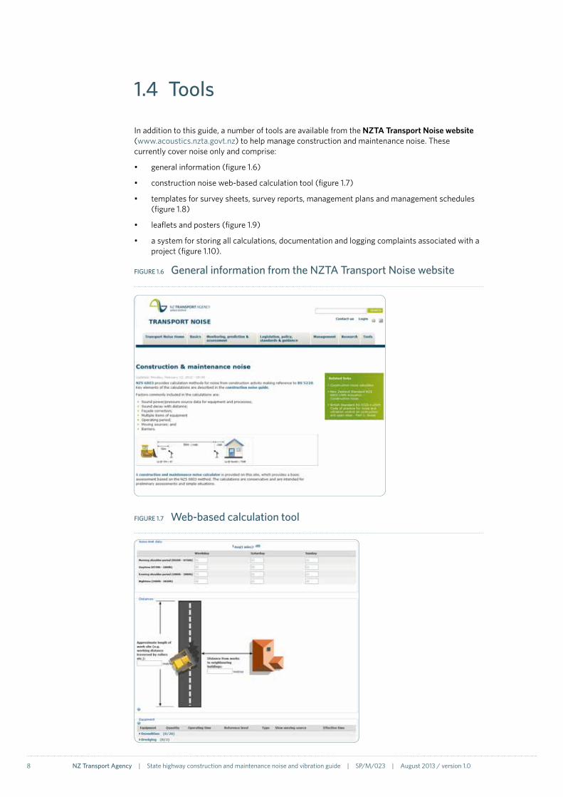
In addition to this guide, a number of tools are available from the NZTA Transport Noise website (www.acoustics.nzta.govt.nz) to help manage construction and maintenance noise. These currently cover noise only and comprise:
• general information (figure 1.6)
• construction noise web-based calculation tool (figure 1.7)
• templates for survey sheets, survey reports, management plans and management schedules (figure 1.8)
• leaflets and posters (figure 1.9)
• a system for storing all calculations, documentation and logging complaints associated with a project (figure 1.10).
FIGURe 1.6 General information from the NZTA Transport Noise website
FIGURe 1.7 Web-based calculation tool

NZ Transport Agency | State highway construction and maintenance noise and vibration guide | SP/M/023 | August 2013 / version 1.0 9
FIGURe 1.8 Templates
FIGURe 1.9 Leaflets and posters
For further information on transport noise please visit www.acoustics.nzta.govt.nz
Minutes
No
ise l
evel, d
B
LAmax
0 60453015
CONTROLSThere are guideline noise limits for construction noise in New Zealand Standard 6803:1999. In some instances alternative criteria are required to allow for night-time work, or houses immediately adjacent to certain daytime works.
The nature of construction activity requires a flexible approach to noise management. The best outcomes for communities and individuals are achieved through proactive management and effective communication. A Construction Noise Management Plan defines consultant and contractor obligations for a project, and provides procedures to ensure good noise control practices are adopted. This includes procedures for maintaining contact with the community and managing noise complaints and contact numbers for key construction and council staff responsible for noise assessment.
It is important that neighbours are forewarned of the nature and timing of construction and maintenance work.
NZ TRaNSpORT ageNCyThe NZ Transport Agency (NZTA) recognises that noise associated with road construction and repairs can be particularly intrusive and disturbing, especially at night.
The NZTA manages and minimises potentially unreasonable noise effects so far as is practicable, in accordance with the New Zealand construction noise standard.
aCOuSTiC TeRmSSound contains different frequency components which are constantly changing. For comparison with noise limits, a standard method must be used to represent varying sound as a construction noise level.
Noise sources cause changes in air pressure which are detected by our ears. These changes in pressure can also be measured by a sound level meter. The pressure changes are expressed in decibels, which is written as “dB”.
Sound can occur across a whole range of frequencies from low frequency rumbles to high frequency chirps. Measured noise levels include all frequencies, but as our hearing is less sensitive to lower frequencies, the measured levels are adjusted to correspond to human hearing. This adjustment is called “A weighting” and is identified by the letter A.
Noise levels fluctuate and therefore it is necessary to consider both average (LAeq) and maximum (LAmax) values. For construction noise, average values are assessed over a time period (t) between fifteen minutes and one hour, as appropriate to the particular activities. The average and maximum levels are shown in the graph below. The LAeq(t) is obtained from an ‘energy’ average of the decibel values; this results in a higher average level than normal arithmetic averaging.
Construction and Maintenance Noise from Roads
WeekdaysSundays
daytime night-time
06
30
07
30
06
30
20
00
18
00
No
ise l
imit
, dB
Noise reduces the further you are from the source. Levels are about 6 dB lower each time you double your distance from the source.
Indicative daily variations of construction noise limits outside neighbouring houses.
v2
10m
20m
40m
80m
160m
80dB
74dB
68dB
62dB
56dB
FIGURe 1.10 Project system

10 NZ Transport Agency | State highway construction and maintenance noise and vibration guide | SP/M/023 | August 2013 / version 1.0
1.5 Noise fundamentals
The purpose of this section is to outline the basic acoustics principles required to understand the concepts presented in this document. Further information on acoustics can be obtained from Wikipedia17.
Sound sources cause changes in air pressure which are detected by our ears and can also be measured by a sound level meter. The pressure changes are expressed in decibels, which is written as ‘dB’. The equation for this uses a logarithmic scale and familiar mathematical rules for addition do not apply, eg 55dB + 55dB = 58dB. An increase of 3dB is a doubling of sound energy. However, in the laboratory, a 3dB increase is only just perceptible to the human ear. As a rule-of-thumb a 10dB increase corresponds approximately to a doubling of perceived loudness, eg 60dB sounds twice as loud as 50dB. Some typical noise levels are presented in figure 1.11.
FIGURe 1.11 Typical noise levels
Road construction and maintenance noise vary considerably, depending on the equipment being used and the distance at which it is being measured. The terrain between the source and the measurement point will also have an effect, particularly if line-of-sight is obstructed, such as by a noise barrier or building.
The difference between the terms ‘sound’ and ‘noise’ is subjective, but generally speaking noise is defined as unwanted sound. In this guide the term ‘noise’ is used to describe the sound/noise produced by construction and maintenance works.
Sound can occur across a whole range of frequencies, from low-frequency rumbles to high-frequency chirps, depending on how fast the air pressure changes are occurring. Where a sound only contains air pressure changes at one distinct frequency, it is described as a ‘tone’. Frequency has the units of cycles per second or hertz (Hz).
Measured construction noise levels include all frequencies, but as our hearing is less sensitive to lower frequencies, the measured levels are adjusted to correspond to human hearing. This adjustment is called ‘A-weighting’ and is identified by the letter A, eg 60dB LAeq(15 min). For simplicity within this document, all sound levels are assumed to be A-weighted unless explicitly stated otherwise.
17 Wikipedia, Acoustics. www.wikipedia.org

NZ Transport Agency | State highway construction and maintenance noise and vibration guide | SP/M/023 | August 2013 / version 1.0 11
FIGURe 1.12 Fluctuating noise and its average and maximum noise levels
LAeq(15 min)
minutes
Noi
se le
vel,
dB
0 15105
LAFmax
Construction and maintenance noise levels fluctuate and typically are assessed using A-weighted average values identified by ‘eq’ for ‘equivalent’ over a set period of 15 minutes, eg LAeq(15min). Figure 1.12 provides an illustration of an average level. The LAeq(15 min) is obtained from an ‘energy’ average of the decibel values; this results in a higher value than normal arithmetic averaging. In addition to an average level, the effects of short duration sounds are assessed using a maximum level: LAFmax. The ‘maximum’ recorded by a sound level meter will depend on the response time of the meter. A sound level meter ‘Fast’ response is standardised as one-eighth of a second, and is identified by the letter F, eg LAFmax.
Airblast overpressure is an additional acoustic effect caused by blasting, where significant airborne energy is generated at frequencies lower than is typically audible by a human ear, but which can cause subsequent vibrations at audible frequencies within buildings (figure 1.13). This is usually quantified in terms of the peak pressure using the linear frequency-weighting: LZpeak.
FIGURe 1.13 | Vibration and airblast propagation
Ground borne propaGation
airborne propaGation
airblast
12 NZ Transport Agency | State highway construction and maintenance noise and vibration guide | SP/M/023 | August 2013 / version 1.0
1.6 Vibration fundamentals
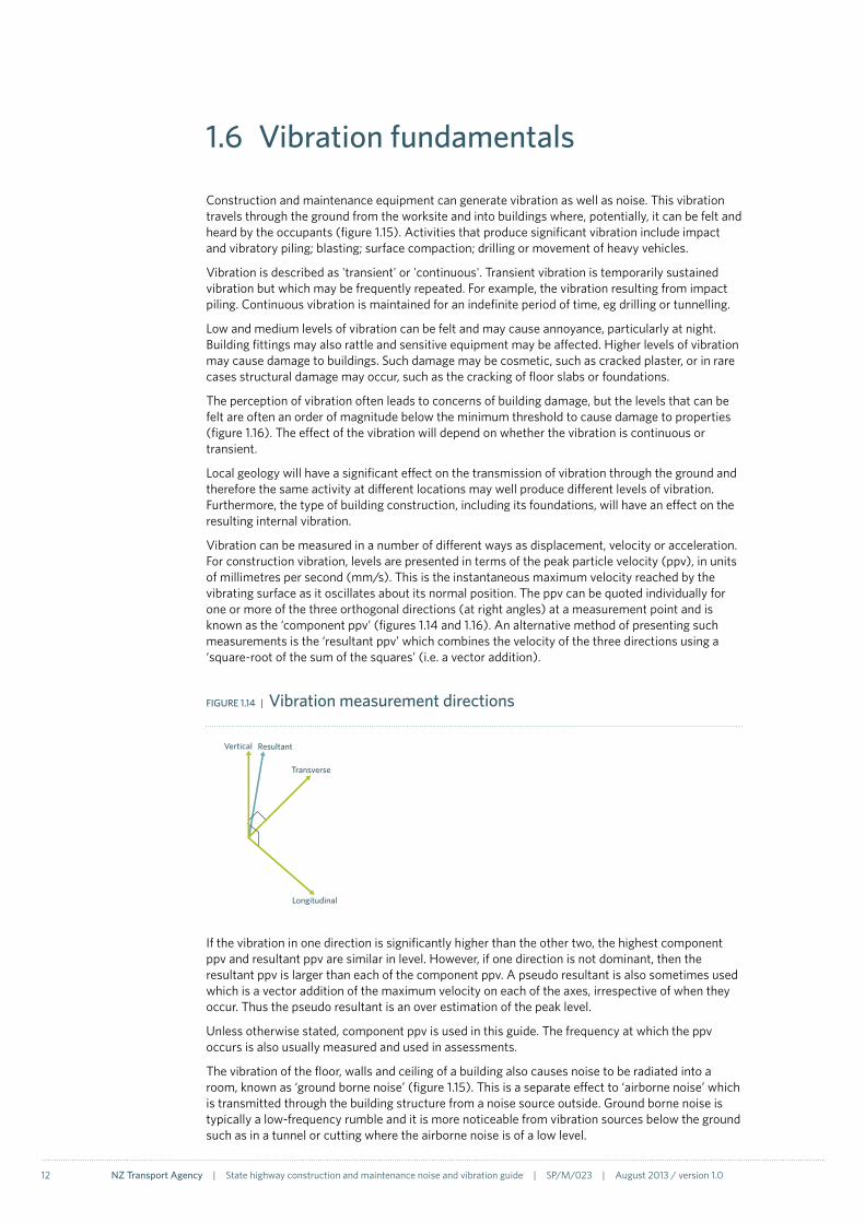
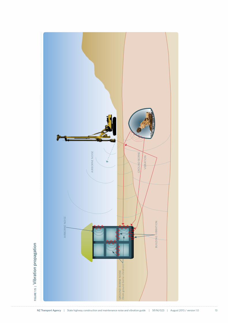
Construction and maintenance equipment can generate vibration as well as noise. This vibration travels through the ground from the worksite and into buildings where, potentially, it can be felt and heard by the occupants (figure 1.15). Activities that produce significant vibration include impact and vibratory piling; blasting; surface compaction; drilling or movement of heavy vehicles.
Vibration is described as 'transient' or 'continuous'. Transient vibration is temporarily sustained vibration but which may be frequently repeated. For example, the vibration resulting from impact piling. Continuous vibration is maintained for an indefinite period of time, eg drilling or tunnelling.
Low and medium levels of vibration can be felt and may cause annoyance, particularly at night. Building fittings may also rattle and sensitive equipment may be affected. Higher levels of vibration may cause damage to buildings. Such damage may be cosmetic, such as cracked plaster, or in rare cases structural damage may occur, such as the cracking of floor slabs or foundations.
The perception of vibration often leads to concerns of building damage, but the levels that can be felt are often an order of magnitude below the minimum threshold to cause damage to properties (figure 1.16). The effect of the vibration will depend on whether the vibration is continuous or transient.
Local geology will have a significant effect on the transmission of vibration through the ground and therefore the same activity at different locations may well produce different levels of vibration. Furthermore, the type of building construction, including its foundations, will have an effect on the resulting internal vibration.
Vibration can be measured in a number of different ways as displacement, velocity or acceleration. For construction vibration, levels are presented in terms of the peak particle velocity (ppv), in units of millimetres per second (mm/s). This is the instantaneous maximum velocity reached by the vibrating surface as it oscillates about its normal position. The ppv can be quoted individually for one or more of the three orthogonal directions (at right angles) at a measurement point and is known as the ‘component ppv’ (figures 1.14 and 1.16). An alternative method of presenting such measurements is the ‘resultant ppv’ which combines the velocity of the three directions using a ‘square-root of the sum of the squares’ (i.e. a vector addition).
Vertical
Transverse
Longitudinal
Resultant
FIGURe 1.14 | Vibration measurement directions
If the vibration in one direction is significantly higher than the other two, the highest component ppv and resultant ppv are similar in level. However, if one direction is not dominant, then the resultant ppv is larger than each of the component ppv. A pseudo resultant is also sometimes used which is a vector addition of the maximum velocity on each of the axes, irrespective of when they occur. Thus the pseudo resultant is an over estimation of the peak level.
Unless otherwise stated, component ppv is used in this guide. The frequency at which the ppv occurs is also usually measured and used in assessments.
The vibration of the floor, walls and ceiling of a building also causes noise to be radiated into a room, known as ‘ground borne noise’ (figure 1.15). This is a separate effect to ‘airborne noise’ which is transmitted through the building structure from a noise source outside. Ground borne noise is typically a low-frequency rumble and it is more noticeable from vibration sources below the ground such as in a tunnel or cutting where the airborne noise is of a low level.
NZ Transport Agency | State highway construction and maintenance noise and vibration guide | SP/M/023 | August 2013 / version 1.0 13
FIG
URe
1.15
| V
ibra
tion
prop
agat
ion
air
born
e n
ois
e
buil
din
G V
ibra
tio
n
air
born
e n
ois
e
Gro
un
d b
orn
e
Vib
rati
on
Gro
un
d b
orn
e n
ois
e (f
rom
gro
und
born
e vi
brat
ion)

14 NZ Transport Agency | State highway construction and maintenance noise and vibration guide | SP/M/023 | August 2013 / version 1.0
FIGURe 1.16 | Vibration levels
Cosmetic damage to unreinforced or light framed structures
at 10 m
Dynam
ic
compaction
Vibrato
ry p
ile d
river
s at 1
0 m
Continuous vibration intolerable
Structural damageCan be tolerated with prior warning
Rotary bored piling at 10 mThreshold of perception
0
5
10
15
2025
30
35
40
45
50
Vibration mm/s
Vibration metricsVibration can be measured as acceleration, velocity or displacement and these measurements can be quantified in terms of various metrics or a spectrum, both with and without frequency weightings.
Commonly found vibration metrics include:
• rmsacceleration,velocityordisplacement-a‘root-mean-squared’averagelevelofthevibration,with or without a frequency weighting
• peakparticlevelocity(ppv)-theinstantaneousmaximumvelocityreachedbythevibratingsurface as it oscillates about its normal position. This metric is used by BS 5228-27 and DIN 4150-318
• vibrationdosevalue(VDV)–a‘root-mean-quad’evaluationoftheweightedacceleration.TheVDV is used in BS 647219 and requires specialist instrumentation. An estimation of the VDV using the rms of the weighted acceleration was recommended in earlier versions of BS 6472 but is no longer advised for vibration with time-varying characteristics or for shocks (which includes construction vibration).
• statisticalmaximumweightedvelocity(v95) or acceleration (a95) – the maximum weighted velocity of acceleration that can be expected with 95% probability. As used in the Norwegian Standard NS 8170.
Peak particle velocity is used exclusively throughout this guide to quantify vibration.
18 German Standard DIN 4150-3:1999 Structural vibration – Effects of vibration on structures. www.din.de
19 BSi (2008) BS 6472-1 Guide to evaluation of human exposure to vibration in buildings – Vibration sources other than blasting. www.bsigroup.com

NZ Transport Agency | State highway construction and maintenance noise and vibration guide | SP/M/023 | August 2013 / version 1.0 15
FIGURe 1.17 | Measurement directions
Vertical
Transverse
Longitudinal
Resultant
Time, minutes
0 0.2 0.4 0.6 0.8 1 1.2 1.4 1.6 1.8 2
0.3
0.4
0.5
0.6
0.2
0.1
0
Resu
ltant
Resultant ppv = 0.57 mm/s
Vib
ratio
n pp
v, m
m/s
0.0
0.2
0.4
0.6
-0.2
-0.4
-0.6
Long
itudi
nal
Longitudinal ppv = 0.14 mm/s
Vib
ratio
n pp
v, m
m/s
Time, minutes
0 0.2 0.4 0.6 0.8 1 1.2 1.4 1.6 1.8 2
2
Vib
ratio
n pp
v, m
m/s
0.0
0.2
0.4
0.6
-0.2
-0.4
-0.6
Tran
sver
se
Transverse ppv = 0.22 mm/s
Time, minutes
0 0.2 0.4 0.6 0.8 1 1.2 1.4 1.6 1.8
0.0
0.2
0.4
0.6
-0.2
-0.4
-0.6
Vert
ical
Vertical ppv = 0.56 mm/s
Vib
ratio
n pp
v, m
m/s
Time, minutes
0 0.2 0.4 0.6 0.8 1 1.2 1.4 1.6 1.8 2


2.1 Noise 18
2.2 Vibration 21
2.3 Ground borne noise 24
2.4 Summary 25
2.5 Best practicable option 26
2.6 Designation conditions 26
Case study – Tauranga eastern Link 29
2 Criteria and legislation
2

18 NZ Transport Agency | State highway construction and maintenance noise and vibration guide | SP/M/023 | August 2013 / version 1.0
2.1 Noise
Most construction and maintenance noise, including for roads, is managed in accordance with New Zealand Standard NZS 6803:1999 Acoustics – Construction noise06. Like all New Zealand standards, NZS 6803 is voluntary unless specifically mandated in a designation condition or a district plan. General construction noise rules in district plans do not apply to designations. The NZTA manages and minimises potentially unreasonable noise effects during state highway construction and maintenance, as far as is practicable, in accordance with this standard.
While this guide and NZS 6803 are focussed on noise from the main construction site, consideration should also be given to off-site effects such as specific construction traffic and general road-traffic on detour routes (section 5.7).
NZS 6803 provides guideline noise criteria for construction and maintenance works (table 2.1). These criteria set out guidelines as to the noise levels people undertaking construction and maintenance works should try to achieve outside neighbouring buildings, 1m from the facades and 1.2–1.5m above the relevant floor level (figure 2.1). These criteria and the requirement to manage noise and vibration effects apply to both residential and commercial/industrial neighbours.
FIGURe 2.1 Airborne noise assessment locations
1m
1.2–1.5m
1.2–1.5m1.2–1.5m
1m
For each time period there are two noise criteria: an average (LAeq(15 min)) and a maximum (LAFmax). For typical daytime construction lasting less than 20 weeks, the guideline criteria are 75dB LAeq(15 min) and 90dB LAFmax. The LAeq(15 min) noise criteria for works lasting less than 20 weeks are also shown graphically in figure 2.2.

NZ Transport Agency | State highway construction and maintenance noise and vibration guide | SP/M/023 | August 2013 / version 1.0 19
TABLe 2.1 Airborne noise criteria
Time of week
Time period
Duration of works at a location
Less than 14 days Less than 20 weeks More than 20 weeks
LAeq(15 min) LAFmax LAeq(15 min) LAFmax LAeq(15 min) LAFmax
Noise criteria at residential neighbours
Weekdays 0630–0730 65dB 75dB 60dB 75dB 55dB 75dB
0730–1800 80dB 95dB 75dB 90dB 70dB 85dB
1800–2000 75dB 90dB 70dB 85dB 65dB 80dB
2000–0630 45dB 75dB 45dB 75dB 45dB 75dB
Saturdays 0630–0730 45dB 75dB 45dB 75dB 45dB 75dB
0730–1800 80dB 95dB 75dB 90dB 70dB 85dB
1800–2000 45dB 75dB 45dB 75dB 45dB 75dB
2000–0630 45dB 75dB 45dB 75dB 45dB 75dB
Sundays and public holidays
0630–0730 45dB 75dB 45dB 75dB 45dB 75dB
0730–1800 55dB 85dB 55dB 85dB 55dB 85dB
1800–2000 45dB 75dB 45dB 75dB 45dB 75dB
2000–0630 45dB 75dB 45dB 75dB 45dB 75dB
Noise criteria at commercial/industrial neighbours
Any day 0730–1800 80dB – 75dB – 70dB –
1800–0730 85dB – 80dB – 75dB –
Adapted from table 2 of NZS 6803:1999. © Copyright Standards New Zealand 2011.
NZS 6803 allows some discretion in the appropriate time period for the LAeq criteria, but for NZTA projects 15 minutes is recommended as a default value.
During the day, most people tolerate higher noise levels from temporary activities, compared to permanent activities. Therefore the guideline criteria for temporary work allow for higher noise levels than would be allowed for permanent activities. However, at night the criteria in the standard are similar to those for permanent activities, to prevent sleep disturbance.
Operational road-traffic noise is assessed under NZS 6806:201020 at Protected Premises and Facilities (PPFs), which include residences, schools, marae and parts of hospitals. For construction noise and vibration, the residential criteria should be applied at the same PPFs defined by NZS 6806, during the times they are occupied.
20 Standards New Zealand (2010) NZS 6806:2010 Acoustics – Road traffic noise – New and altered roads. www.standards.co.nz

20 NZ Transport Agency | State highway construction and maintenance noise and vibration guide | SP/M/023 | August 2013 / version 1.0
NZS 6803P:1984The first standard in the NZS 6803 construction noise standard series was published as a provisional standard in 198421, with the aim of gathering feedback from users. Initially, few issues arose, and unusually the standard fell into common use even though it was still only provisional. Numerous district plans and designation conditions still reference the old provisional standard (NZS 6803P:1984). Eventually the standard was revised and published as a full standard in 1999.
The noise criteria in the 1984 and 1999 versions of the standard are identical, other than a change in the descriptor used from LA10 to LAeq(15 min). The key difference is that the 1999 version is expanded to outline significant processes such as the use of management plans. The 1999 version acknowledges that the guideline noise criteria in the standard might not be achievable in all instances.
In law, the specific version of a standard quoted in a designation condition is the version that applies, regardless of whether it has been superseded. However, in the case of NZS 6803, because the noise criteria are essentially the same, and as the 1999 version adds good practice management techniques, most acoustics specialists apply the 1999 version even when the 1984 provisional version is specified. The NZTA uses the 1999 version as good practice.
21 Standards New Zealand (1984) NZS 6803P:1984 The measurement and assessment of noise from construction, maintenance and demolition work, provisional. www.standards.co.nz
FIGURe 2.2 Guideline residential neighbour criteria for construction lasting less than 20 weeks
Construction and maintenance at night may result in unavoidable noise levels that exceed the guideline night-time criteria in the standard. Therefore, if such works are necessary and justified at night, the night-time noise criteria set for a project may need to exceed those in the standard (section 5.6). The reasons for this should be clearly recorded, and the effects managed through a Construction Noise and Vibration Management Plan (CNVMP). The NZTA should still ensure that alternative night-time noise criteria are both reasonable and practicable. Specific criteria above those in NZS 6803 may also be required for particular daytime activities, particularly where neighbouring houses are immediately adjacent to the works. One situation where it may be reasonable to vary noise criteria (particularly at night) is where there are already elevated ambient noise levels.
In cases where alternative noise criteria are required, the NZTA planners and project managers should consult with the Environment and Urban Design team ([email protected]). Alternative noise criteria should be explicitly allowed for in the designation conditions. Consideration in advance of construction/maintenance and engagement with the regulatory authority is essential to deliver workable noise criteria, but still appropriately address noise impacts.
daytime night-time
0630
0730
0630
2000
1800
Noi
se c
riter
ion,
dB Weekdays
Sundays
Derived from table 2 of NZS 6803:1999. © Copyright Standards New Zealand 2011.
50
60
55
70
75
45
NZ Transport Agency | State highway construction and maintenance noise and vibration guide | SP/M/023 | August 2013 / version 1.0 21
2.2 Vibration
In the absence of a New Zealand vibration standard, reference is often made to the German Standard DIN 4150-318 or the British Standard BS 5228-207. The British standard includes consideration of effects on people, buildings, building contents and underground services. Part 3 of the German standard only includes effects on buildings.
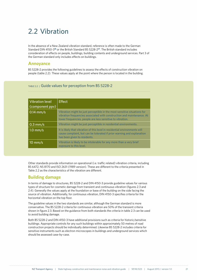
AnnoyanceBS 5228-2 provides the following guidelines to assess the effects of construction vibration on people (table 2.2). These values apply at the point where the person is located in the building.
Other standards provide information on operational (i.e. traffic related) vibration criteria, including BS 6472, NS 8170 and ISO 2631 (1989 version). These are different to the criteria presented in Table 2.2 as the characteristics of the vibration are different.
Building damageIn terms of damage to structures, BS 5228-2 and DIN 4150-3 provide guideline values for various types of structure for cosmetic damage from transient and continuous vibration (figures 2.3 and 2.4). Generally the values apply at the foundation or base of the building on the side facing the source of vibration. Additionally, for continuous vibration, DIN 4150-3 specifies criteria for the horizontal vibration on the top floor.
The guideline values in the two standards are similar, although the German standard is more conservative. The BS 5228-2 criteria for continuous vibration are 50% of the transient criteria shown in figure 2.3. Based on the guidance from both standards the criteria in table 2.3 can be used to avoid building damage.
Both BS 5228-2 and DIN 4150-3 have additional provisions such as criteria for historic/sensitive buildings. Appropriate controls for any such buildings within approximately 50 metres of road construction projects should be individually determined. Likewise BS 5228-2 includes criteria for sensitive instruments such as electron microscopes in buildings and underground services which should be assessed case-by-case.
TABLe 2.2 | Guide values for perception from BS 5228-2
Vibration level(component ppv)
effect
0.14 mm/s Vibration might be just perceptible in the most sensitive situations for vibration frequencies associated with construction and maintenance. At lower frequencies, people are less sensitive to vibration.
0.3 mm/s Vibration might be just perceptible in residential environments.
1.0 mm/s It is likely that vibration of this level in residential environments will cause complaint, but can be tolerated if prior warning and explanation has been given to residents.
10 mm/s Vibration is likely to be intolerable for any more than a very brief exposure to this level.

22 NZ Transport Agency | State highway construction and maintenance noise and vibration guide | SP/M/023 | August 2013 / version 1.0
FIGURe 2.3 | BS 5228-2 transient vibration criteria for houses
FIGURe 2.4 | Comparison of transient criteria from different standards
0
50
100
150
200
250
0 10 20 30 40 50 60 70 80 90 100
Com
pone
nt p
pv, m
m/s
Frequency, Hz
Major damage
Minor damage
Cosmetic damage
Com
pone
nt p
pv, m
m/s
Frequency, Hz
DIN 4150-3
BS 5228-2 Cosmetic damage
0
10
20
30
40
60
0 10 20 30 40 50 60 70 80 90 100
50
Note: At frequencies below 4 Hz, BS 5228-2 states that a minimum displacement of 0.6 mm (zero to peak) is not to be exceeded. This criterion has been included on the above graph as a dashed line representing the equivalent ppv of sinusoidal vibration.
NZ Transport Agency | State highway construction and maintenance noise and vibration guide | SP/M/023 | August 2013 / version 1.0 23
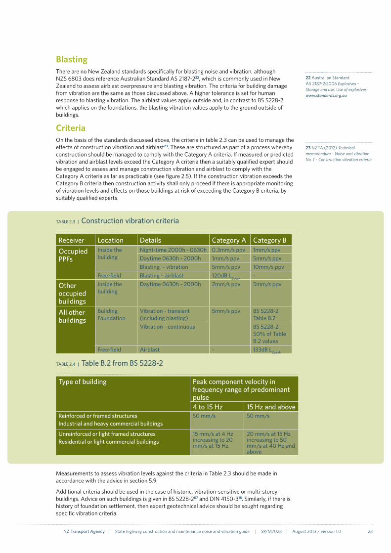
TABLe 2.3 | Construction vibration criteria
Receiver Location Details Category A Category BOccupied PPFs
Inside the building
Night-time 2000h - 0630h 0.3mm/s ppv 1mm/s ppvDaytime 0630h - 2000h 1mm/s ppv 5mm/s ppvBlasting – vibration 5mm/s ppv 10mm/s ppv
Free-field Blasting – airblast 120dB LZpeak -
Other occupied buildings
Inside the building
Daytime 0630h - 2000h 2mm/s ppv 5mm/s ppv
All other buildings
Building Foundation
Vibration - transient (including blasting)
5mm/s ppv BS 5228-2 Table B.2
Vibration - continuous BS 5228-2 50% of Table B.2 values
Free-field Airblast - 133dB LZpeak
BlastingThere are no New Zealand standards specifically for blasting noise and vibration, although NZS 6803 does reference Australian Standard AS 2187-222, which is commonly used in New Zealand to assess airblast overpressure and blasting vibration. The criteria for building damage from vibration are the same as those discussed above. A higher tolerance is set for human response to blasting vibration. The airblast values apply outside and, in contrast to BS 5228-2 which applies on the foundations, the blasting vibration values apply to the ground outside of buildings.
CriteriaOn the basis of the standards discussed above, the criteria in table 2.3 can be used to manage the effects of construction vibration and airblast23. These are structured as part of a process whereby construction should be managed to comply with the Category A criteria. If measured or predicted vibration and airblast levels exceed the Category A criteria then a suitably qualified expert should be engaged to assess and manage construction vibration and airblast to comply with the Category A criteria as far as practicable (see figure 2.5). If the construction vibration exceeds the Category B criteria then construction activity shall only proceed if there is appropriate monitoring of vibration levels and effects on those buildings at risk of exceeding the Category B criteria, by suitably qualified experts.
Measurements to assess vibration levels against the criteria in Table 2.3 should be made in accordance with the advice in section 5.9.
Additional criteria should be used in the case of historic, vibration-sensitive or multi-storey buildings. Advice on such buildings is given in BS 5228-207 and DIN 4150-318. Similarly, if there is history of foundation settlement, then expert geotechnical advice should be sought regarding specific vibration criteria.
23 NZTA (2012) Technical memorandum – Noise and vibration No. 1 – Construction vibration criteria.
22 Australian Standard AS 2187-2:2006 Explosives –Storage and use: Use of explosives. www.standards.org.au
Type of building Peak component velocity in frequency range of predominant pulse4 to 15 Hz 15 Hz and above
Reinforced or framed structuresIndustrial and heavy commercial buildings
50 mm/s 50 mm/s
Unreinforced or light framed structuresResidential or light commercial buildings
15 mm/s at 4 Hz increasing to 20 mm/s at 15 Hz
20 mm/s at 15 Hz increasing to 50 mm/s at 40 Hz and above
TABLe 2.4 | Table B.2 from BS 5228-2

24 NZ Transport Agency | State highway construction and maintenance noise and vibration guide | SP/M/023 | August 2013 / version 1.0
FIGURe 2.5 | Assessment of vibration and airblast
Preliminary assessment
No further assessment required, carry out works
yes
No
Further assessment by Acoustics Specialist to confirm levels, determine mitigation options and monitoring requirements (section 4)
Initial building condition surveys for properties that might exceed Category A (section 5.5)
Carry out worksCarry out works with continuous monitoring (section 5.9)
Final building condition surveys (section 5.5)
yes NoIs
Category B likely to be exceeded?
Could Category A be exceeded?
2.3 Ground borne noise
New Zealand and international standards do not provide criteria for ground borne noise. For most construction activities such as piling the airborne noise is dominant and is controlled using NZS 680306, so separate criteria for ground borne noise are not required. However, for tunnelling there is no airborne noise so ground borne noise criteria are needed. The criteria in table 2.5 (based on the Waterview project) could be used in a management process in the same manner as the vibration criteria (section 2.2).
Space Time Category A Category BBedroom 2000h - 0630h 30dB LAeq(15 min) 35dB LAeq(15 min)
Other habitable spaces
0630h – 2000h 35dB LAeq(15 min) 40dB LAeq(15 min)
TABLe 2.5 | Ground borne noise criteria

NZ Transport Agency | State highway construction and maintenance noise and vibration guide | SP/M/023 | August 2013 / version 1.0 25
2.4 SummaryFI
GU
Re 2
.6 |
Sum
mar
y of
app
licab
le s
tand
ards
and
mea
sure
men
t loc
atio
ns
1m
Airb
last
A
S 21
87-2
Gro
und
born
e vi
brat
ion
AS
2187
-2
Gro
und
born
e no
ise
Gro
und
born
e vi
brat
ion
(bui
ldin
g da
mag
e)BS
522
8-2
or D
IN 4
150-
3G
roun
d bo
rne
vibr
atio
n (a
nnoy
ance
)BS
522
8-2
Airb
orne
noi
seN
ZS 6
803
Free
-fiel
d

26 NZ Transport Agency | State highway construction and maintenance noise and vibration guide | SP/M/023 | August 2013 / version 1.0
2.6 Designation conditions
As noted in section 2.5, most road construction works are controlled by the conditions of designations and resource consents. For new designations and consents it is important that conditions are drafted to both protect neighbours and allow practicable road construction methods. A guide to drafting conditions under the RMA is provided by the Ministry for the Environment24.
There is often a strong desire for the comfort and certainty of rigid limits in conditions, but in the case of construction noise and vibration this is not appropriate. Sensitivity to construction noise and vibration can vary substantially between buildings and people and it is not possible to detail separate criteria for the often hundreds of different circumstances on a particular project. At a simple level, sensitivity can depend on when different houses are occupied or unoccupied, for example. However, more complex factors include the effectiveness of management measures such as communication and stakeholder engagement.
Significant infrastructure projects could not be built in urban areas if rigid compliance to the guideline noise criteria in NZS 6803 was mandatory.
The aim of conditions for construction activities should be to include criteria as a trigger for certain management actions under a comprehensive framework. Model construction designation conditions are presented on the following pages.
For high risk projects, where there are not designation conditions relating to construcation noise or vibration, or where conditions are less detailed than the model conditions, then the intent of the model conditions should be covered in the contract documents for the physical works.
Maintenance activities are not usually subject to noise and vibration controls in designation conditions. Regardless, requirements to follow the good practice described in this guide should be included in NZTA maintenance contracts.
For prolonged works where a property is subject to exceptionally high construction noise and/or vibration exposure and other project related effects it may be appropiate to consider including the property in the designation and seeking for the crown to purchase it under the Public Works Act 1981 .
24 Ministry for the Environment (1991) Effective and enforceable consent conditions – A guide to drafting conditions under the Resource Management Act. www.mfe.govt.nz
2.5 Best practicable option
Under the RMA there is an overarching requirement in section 16(1) to adopt the best practicable option to ensure that the emission of noise and vibration does not exceed a reasonable level. However, where a designation condition (or resource consent) contains a specific construction noise and vibration condition, it is that condition which the person undertaking the project must comply with. Section 17 of the RMA also imposes a duty to avoid adverse effects in general.
The criteria presented in the preceding sections are specifically designed to result in reasonable levels of noise and vibration. However, there may be specific circumstances or types of noise/vibration where compliance with the criteria would not result in a reasonable level. There are also many occasions when it is not practicable for construction activity to achieve the guideline criteria in the standard. In any such circumstances, desgination conditions that are consistent with the best practicable option should be adopted.
The RMA defines the best practicable option in this context as:
…the best method for preventing or minimising the adverse effects on the environment having regard, among other things, to—
a. the nature of the discharge or emission and the sensitivity of the receiving environment to adverse effects, and
b. the financial implications, and the effects on the environment, of that option when compared with other options, and
c. the current state of technical knowledge and the likelihood that the option can be successfully applied.

NZ Transport Agency | State highway construction and maintenance noise and vibration guide | SP/M/023 | August 2013 / version 1.0 27
If there are historic/vibration sensitive buildings or multi-storey buildings near to the construction works then individual assessment should be made and where appropriate additional vibration criteria should be added to the designation conditions in accordance with DIN 4150/BS 5228.
If there is a history of foundation settlement in the vicinity of the proposed construction works, the model vibration criteria may not be adequate to prevent vibration induced foundation settlement. In such situations, expert advice should be sought from a geotechnical engineer as to what site specific vibration limits should apply. Non-cohesive soils, such as uniformly graded sand or silt, are particularly vulnerable to dynamically induced settlement.
The NZTA uses the online database CSVue (www.csvue.com) for consent management, and this includes details of all existing designation conditions. Contact the NZTA Environment and Urban Design team ([email protected]).
Model conditionsThe following conditions have been drafted primarily for high risk projects. For low and medium risk projects construction noise and vibration can usually be addressed through general requirements for a Social and Environmental Management Plan. These model conditions are structured around a Construction Noise and Vibration Management Plan (section 5.10). Criteria for blasting have not been included in these conditions as it is not required for many projects (refer section 2.2). These conditions may require adaptation to address the specific issues on a particular project.
Condition C1The NZTA shall implement a Construction Noise and Vibration Management Plan (CNVMP) throughout the entire construction period of the Project. The CNVMP shall be provided to the [council officer] for certification that it addresses Conditions [C1] to [C4] prior to commencement of construction of the project.
The CNVMP must describe the measures adopted to seek to meet:
• the noise criteria set out in Condition [C3] below, where practicable. Where it is not practicable to achieve those criteria, alternative strategies should be described to address the effects of noise on neighbours, e.g. by arranging alternative temporary accommodation; and
• the Category A vibration criteria set out in Condition [C4] below, where practicable. Where it is not practicable to achieve those criteria, a suitably qualified expert shall be engaged to assess and manage construction vibration during the activities that exceed the Category A criteria. If predicted construction vibration exceeds the Category B criteria then construction activity should, where practicable, only proceed if approved by [council officer] and if there is appropriate monitoring of vibration levels and effects on buildings at risk of exceeding the Category B criteria, by suitably qualified experts.
The CNVMP shall, as a minimum, address the following:
• Description of the works, anticipated equipment/processes and their scheduled durations.• Hours of operation, including times and days when construction activities causing noise and/or
vibration would occur.• The construction noise and vibration criteria for the project.• Identification of affected houses and other sensitive locations where noise and vibration criteria
apply.• Requirement for building condition surveys at locations close to activities generating significant
vibration, prior to and after completion of the works (including all buildings predicted to exceed the Category A vibration criteria in Condition [C4]).
• Mitigation options, including alternative strategies where full compliance with the relevant noise and/or vibration criteria cannot be achieved.
• Details of which operational road-traffic noise mitigation options as required by Condition [C2] below will be implemented early enough to also mitigate construction noise.
• Management schedules containing site specific information.• Methods and frequency for monitoring and reporting on construction noise and vibration.• Procedures for maintaining contact with stakeholders, notifying of proposed construction activities
and handling noise and vibration complaints.• Construction equipment operator training procedures and expected construction site behaviours.• Contact numbers for key construction staff, staff responsible for noise assessment and council
officers.

28 NZ Transport Agency | State highway construction and maintenance noise and vibration guide | SP/M/023 | August 2013 / version 1.0
TABLe 2.6 Construction noise criteria
Day Time LAeq(15min) LAFmax
Occupied PPFs (as defined in NZS 6806:2010)Weekdays 0630h - 0730h [level] dB [level] dB
0730h - 1800h [level] dB [level] dB1800h - 2000h [level] dB [level] dB2000h - 0630h [level] dB [level] dB
Saturday 0630h - 0730h [level] dB [level] dB0730h - 1800h [level] dB [level] dB1800h - 2000h [level] dB [level] dB2000h - 0630h [level] dB [level] dB
Sundays and public holidays
0630h - 0730h [level] dB [level] dB0730h - 1800h [level] dB [level] dB1800h - 2000h [level] dB [level] dB2000h - 0630h [level] dB [level] dB
Commercial and industrial receiversAll 0730h – 1800h [level] dB [level] dB
1800h – 0730h [level] dB [level] dB
TABLe 2.7 Construction vibration criteria
Reciever Details Category A Category B
PPFs Night-time 2000h - 0630h
0.3mm/s ppv 1mm/s ppv
Daytime 0630h - 2000h
1mm/s ppv 5mm/s ppv
Other occupied buildings
Daytime 0630h - 2000h
2mm/s ppv 5mm/s ppv
All other buildings Vibration - transient 5mm/s ppv BS 5228-2*1
Table B.2
Vibration - continuous BS 5228-2*1
50% of Table B.2 values
*1 BS 5228-2:2009 ‘Code of practice for noise and vibration control on construction and open sites – Part 2: Vibration’
Condition C4Construction vibration must be measured in accordance with ISO 4866:2010 Mechanical vibration and shock – Vibration of fixed structures – Guidelines for the measurement of vibrations and evaluation of their effects on structures. The construction vibration criteria for the purposes of the CNVMP are:
Condition C2The NZTA should, where practicable, implement those Structural Mitigation and Building-Modification Mitigation measures for operational noise detailed in Conditions [insert reference numbers of operational road-traffic noise conditions] which are identified in the CNVMP as also providing construction noise mitigation, prior to commencing major construction works that would be attenuated by these mitigation measures.
Condition C3Construction noise must be measured and assessed in accordance with NZS 6803:1999 ‘Acoustics - Construction Noise’. The construction noise criteria for the purposes of the CNVMP are [insert project specific criteria where appropriate]:

NZ Transport Agency | State highway construction and maintenance noise and vibration guide | SP/M/023 | August 2013 / version 1.0 29
Case study – Tauranga Eastern Link (2011)The Tauranga Eastern Link (TEL) is a 23km four-lane highway between Te Maunga and Paengaroa. The first 6km of the route is the widening of an existing two-lane road, and the remaining 17km is a new road. The project includes approximately 2.5 million m3 of earthworks, 136 culverts and 7 bridges.
The TEL spans three designations which had been established at different times. Each designation is subject to different conditions for construction noise. Generally in such cases consideration should be given to altering the designations to provide a consistent set of conditions. In this instance the differences were not significant and the existing conditions were retained, although the same construction noise management practices were applied throughout the works.
The conditions for construction noise for the TEL illustrate some key issues with many existing construction noise conditions that the NZTA is seeking to avoid by promoting use of the model conditions shown opposite. The difficulties with the TEL conditions are common for many existing NZTA designations as well as resource consents and designations for most commercial and industrial activities.
TeL Te MAUNGA FOUR-LANING DeSIGNATION
• The conditions include that construction noise ‘shall meet the limits recommended in table 1 of NZS 6803P:1984’. This condition is problematic in that for most road construction works near houses it is not practicable to achieve perfect compliance with the guideline limits in this provisional standard. The condition is also problematic in that it references the 1984 provisional version of NZS 6803 which does not allow for modern measurement, analysis and management practices.
• The conditions include restrictions such as ‘requiring engines to be fitted with effective exhaust silencers’ and ‘requiring construction equipment to be kept in good repair’. While these requirements are consistent with good management of construction noise, they are too general as conditions and it is doubtful how they could be enforced. Such issues are better addressed through the CNVMP, which can adapt to the specific effects, activity and location, once the construction methodology is confirmed.
• The conditions also include requirements for communication with neighbours, which again are better addressed by the CNVMP.
TeL SANDHURST INTeRCHANGe AND TAURANGA eASTeRN ARTeRIAL DeSIGNATIONS
Both these designations have similar construction noise conditions, which raise the same issues.
• The conditions require compliance with NZS 6803:1999, but do not specify any noise criteria. This creates the same issues as for the Te Maunga designation above. Furthermore, the 1999 version of the standard is explicit that noise criteria should be stated in conditions rather than simply relying on reference to the standard.
• The conditions require a management plan rather than specifying particular mitigation methods, which is good. However, for the Tauranga Eastern Arterial designation there are no requirements for what the plan should include, as shown in the model conditions.
FIGURe 2.7 TeL route


3.1 Construction project stages 32
3.2 Maintenance stages 33
3.3 Scope of works 33
3.4 Tier 1 – Risk assessment - 34 construction
3.5 Tier 2 – Screening assessment - construction and maintenance 35
3.6 Tier 3 – Assessment 36
3.7 Reporting 38
3 NZTA processes
3

32 NZ Transport Agency | State highway construction and maintenance noise and vibration guide | SP/M/023 | August 2013 / version 1.0
3.1 Construction project stages
The NZTA has adopted a three-tiered approach to construction noise and vibration assessment, as shown in figure 3.1. For most projects, detailed assessment of noise and vibration are not appropriate during the investigation stage. Construction noise and vibration can be addressed using standard processes specified in this guide, and detailed assessment is best conducted once a contractor is appointed and specific known activities and equipment can be considered. For many projects the Tier 1 and 2 assessments can be quickly conducted by NZTA project staff without the need for acoustics specialists. Tier 3 assessments are not required on all projects but may require the use of acoustics specialists.
For construction projects, the left side of figure 3.1 shows NZTA state highway project stages. The appropriate tier of assessment varies for each stage depending on the ‘noise and vibration risk’ associated with the project. The risk is determined from the Tier 1 assessment. Projects do not always exactly follow the progression of project stages shown in figure 3.1. For the purposes of noise and vibration assessment, the scheme assessment phase of the project has been split into three stages, although the division is not a formal part of NZTA processes.
FIGURe 3.1 Assessment process - construction
Stage Noise and vibration assessment tier Item
INV
eSTI
GAT
ION
ScopingScoping Report
Scheme Assessment 1(feasibility/scoping update)
Scheme Assessment 2Scheme Assessment Report (SAR)
Tier
1 –
Risk
ass
essm
ent
All projects
High risk projects
only
Project dependent
DeS
IGN
ConstructImplement CNVMP
DesignOutline Plan of Works CNVMP
FeA
SIBI
LITy Feasibility
Project Feasibility Report
Scheme Assessment 3Assessment of Environmental Effects (AEE) / Notice of Requirement (NoR)
CON
STRU
CT
Tier
3 –
Noi
se a
nd
vibr
atio
n as
sess
men
t
Tier
2 –
Scr
eeni
ng
All projects
NZ Transport Agency | State highway construction and maintenance noise and vibration guide | SP/M/023 | August 2013 / version 1.0 33
3.2 Maintenance stages
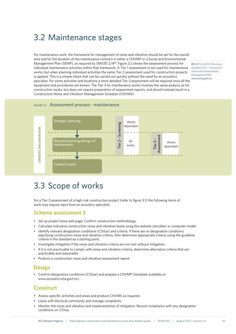
For maintenance work, the framework for management of noise and vibration should be set for the overall area and for the duration of the maintenance contract in either a CNVMP or a Social and Environmental Management Plan (SEMP), as required by SM030 Z/425. Figure 3.2 shows the assessment process for individual maintenance activities within that framework. A Tier 1 assessment is not used for maintenance works, but when planning individual activities the same Tier 2 assessment used for construction projects is applied. This is a simple check that can be carried out quickly without the need for an acoustics specialist. For some activities and locations a more detailed Tier 3 assessment will be required once all the equipment and procedures are known. The Tier 3 for maintenance works involves the same analysis as for construction works, but does not require preparation of assessment reports, and should instead result in a Construction Noise and Vibration Management Schedule (CNVMS).
FIGURe 3.2 Assessment process - maintenance
OPe
RATe
AN
D M
AIN
TAIN
Strategic planning
Detailed planning/design of maintenance
Tier
3 –
A
sses
smen
t
All works
Works dependantTi
er 2
– S
cree
ning
Conduct works
Works dependant
3.3 Scope of worksFor a Tier 3 assessment of a high-risk construction project (refer to figure 3.1) the following items of work may require input from an acoustics specialist.
Scheme assessment 3• Set up project noise web page. Confirm construction methodology.• Calculateindicativeconstructionnoiseandvibrationlevelsusingthewebsitecalculatororcomputermodel.• Identifyrelevantdesignationconditions(CSVue)andcriteria.Iftherearenodesignationconditions
specifying construction noise and vibration criteria, then determine appropriate criteria using the guideline criteria in the standard as a starting point.
• Investigatemitigationifthenoiseandvibrationcriteriaarenotmetwithoutmitigation.• Ifitisnotpracticabletocomplywithnoiseandvibrationcriteria,determinealternativecriteriathatare
practicable and reasonable.• Produceaconstructionnoiseandvibrationassessmentreport.
Design• Confirmdesignationconditions(CSVue)andprepareaCNVMP(templateavailableon
www.acoustis.nzta.govt.nz).
Construct• AssessspecificactivitiesandareasandproduceCNVMSasrequired.• Liaisewiththelocalcommunityandmanagecomplaints.• Monitorthenoiseandvibrationandimplementationofmitigation.Recordcompliancewithanydesignation
conditions on CSVue.
25 NZTA (2010) Minimum standard Z/4 – Contractor’s Social and Environmental Management Plan. www.nzta.govt.nz

34 NZ Transport Agency | State highway construction and maintenance noise and vibration guide | SP/M/023 | August 2013 / version 1.0
3.4 Tier 1 – Risk assessment - construction
A tier 1 assessment is only required for construction projects and provides an indication of the ‘noise and viration risk’ associated with a project option. Risk in this context is both the risk of works causing annoyance or building damage, and also the related risks of costly mitigation or affecting statutory approvals.
The assessment is a simple process that can be completed in a matter of minutes by a non-specialist. It is based on the length of the works, the location and the number of protected premises and facilities (PPFs) within 200m of the proposed alignment. PPFs are defined in NZS 6806:201020 and include buildings such as houses and schools. Although the definition of PPFs comes from NZS 6806 for operational road-traffic noise rather than NZS 6803 for construction noise, it has been used in this instance to provide consistency and efficiency between the tier 1 assessments for both aspects. An estimate of these parameters will usually be sufficient to determine the appropriate category using figure 3.3.
The tier 1 assessment forms part of the social and environmental screen (SES) required by minimum standard Z/1926. The results of the assessment are to be reported on form PSF/1327 as shown in section 3.7, together with the assessments of other potential social and environmental effects required by Z/19. As the project progresses through feasibility, scoping, and the beginning of scheme assessment, the assessment for each current option should be reviewed and updated as necessary. No reporting other than PSF/13 is required for tier 1 assessments.
Beside each flowchart on the following pages is a list of the tools available to NZTA staff and consultants. Many of these tools are on the Transport Noise website www.acoustics.nzta.govt.nz. Within the website results from tools can be saved in a central location for each project. Instructions for doing this are provided on the website.
27 NZTA (2010) Social and environmental management form, PSF 13, version 2. www.nzta.govt.nz
26 NZTA (2010) Minimum standard Z/19 – Social and environmental management. www.nzta.govt.nz
FIGURe 3.3 Risk rating
50
200
1 10
PPFs
with
in 2
00m
Length of works, km
High risk
Medium risk
Low risk

NZ Transport Agency | State highway construction and maintenance noise and vibration guide | SP/M/023 | August 2013 / version 1.0 35
3.5 Tier 2 – Screening assessment - construction and maintenance
A detailed noise and vibration assessment is only required where there are certain construction activities near to PPFs. In other cases, standard management processes can be adopted without the need for a detailed assessment at the assessment of environmental effects (AEE) stage for construction projects. The purpose of a tier 2 assessment is to screen out those projects and works where detailed assessment is not required. A tier 2 screening assessment is carried out by answering the questions in table 3.1. Further work in a tier 3 assessment is required if any one of the first group of questions is answered positively, or if three or more of the second group are answered positively.
For maintenance works, the outcome of the tier 2 assessment should be recorded in the work plan for the activity.
For construction projects, the tier 2 noise and vibration assessment forms part of the social and environmental assessment (SEA) required by minimum standard Z/19. The results of this screening assessment should be recorded on form PSF/13 as shown in section 3.7. The screening assessment should be reviewed and updated if changes are made to the proposed construction methodology. For scoping reports and scheme assessment reports the tier 2 noise and vibration assessment should comprise just PSF/13.
At this stage mitigation options should be identified, together with indicative costs for implementation. These should be determined on the basis of professional judgement informed by previous similar projects, rather than detailed acoustics analysis. Consideration should be given to the value-for-money provided by different options.
TABLe 3.1 Screening assessment
Within 20m of a PPF or historic structure:
Is mechanical digging to be undertaken?
Tier 3 required if any questions answered positively
Within 30m of a PPF or historic structure:
Is vibratory piling to be used?
Within 50m of a PPF:Is any work to be carried out at the weekend?
Is any work to be carried out at night?
Within 70m of a PPF or historic structure:
Is impact or percussion piling to be used?
Is blasting required?
Does the district plan or existing designation conditions require absolute compliance with any construction noise limits?
Are the works within 100 metres of a PPF?
Tier 3 required if any three questions answered positively
Within 100m of a PPF will there be works for longer than 6 months?
Is tracked equipment to be used?
Will there be a batching plant on site?
Is rock breaking required on site?
Is fill/cut or bulk materials to be transported via local roads rather than state highways?
Are there any PPFs with particular sensitivity to noise? (Have complaints been received before at this location?)
Does the district plan or existing designation conditions set criteria more stringent than NZS 6803:1999?

36 NZ Transport Agency | State highway construction and maintenance noise and vibration guide | SP/M/023 | August 2013 / version 1.0
3.6 Tier 3 – Assessment
A Tier 3 assessment covers the detailed analysis of noise and vibration that may occur at different stages of construction projects and maintenance works, depending on the specific activity and location. For all high-risk projects that require a tier 3 assessment, this assessment will be undertaken by an acoustic specialist. A Tier 3 assessment can result in an assessment report for an AEE, a CNVMP or a CNVMS.
Basic Tier 3 assessments can be completed by a non-specialist using the construction noise calculator on the Transport Noise website (section 4.3). If equipment is to be used that generates vibration, this should also be predicted using the methods described in this document (section 4). The Tier 3 assessment is made on the basis of estimated details of the works: the methodology and the relationship to the nearest PPF. The methodology includes the equipment to be used plus when and where it will be operating. Complex scenarios may require computer modelling by an acoustics specialist (section 4.4). As a guide, complex scenarios may contain one or more of the following: terrain or barriers that provide screening of noise; five or more items of equipment operating intermittently; multiple works areas within the site; blasting; or use of a haul road to move materials.
The output from a Tier 3 assessment for a construction project at the investigation stage is a construction noise and vibration assessment report for an AEE. For high risk projects, contractors should be required to describe in their tenders how they will deliver the outcomes sought in that assessment report and suggest any improvements. When the construction tender has been awarded, for those high risk projects, the contractor should be required to prepare a CNVMP.
The detailed assessment of noise and vibration from a construction project and implementation of the CNVMP continues in the design and construct stages as shown in figure 3.5. An example of a more detailed specific assessment process and mitigation response adopted for the Waterview Connection (2011) is shown on page 79.
For maintenance works, an overarching CNVMP or SEMP is required by SM030 Z/425, covering a maintenance programme. Specific activities that required a Tier 3 assessment should then be managed through a Construction Noise and Vibration Management Schedule (CNVMS).
FIGURe 3.4 Tier 3 – design and construct stages
Prepare CNVMP, upload and submit to council if required under designation conditions
During works, conduct regular community liaison plus noise and vibration monitoring. Record monitoring on project web page
Assess specific activities/areas and prepare Construction Noise and Vibration Management Schedules (CNVMSs). Upload and submit to council if required under designation conditions
Record compliance with construction noise and vibration designation conditions on CSVue
No
yesInvestigate and resolve complaint. Record details on project web page
Complaints received?
CNVMP template, project pages www.acoustics.nzta.govt.nz
CNVMP template, project pages www.acoustics.nzta.govt.nz
Noise survey sheet, noise survey report template, project pages www.acoustics.nzta.govt.nz
Project pages www.acoustics.nzta.govt.nz
CSVue www.csvue.com

NZ Transport Agency | State highway construction and maintenance noise and vibration guide | SP/M/023 | August 2013 / version 1.0 37
FIGURe 3.5 Tier 3 – investigation stage for a construction project
Set up project noise and vibration web page
yes
No
Look up guideline noise criteria in NZS 6803:1999 and the district planLook up vibration criteria in this guide
Site visitIdentify PPFs
Determine construction methodology
Predict noise and vibration levels
Identify relevant designation conditions
yes
No Investigate mitigation
yes
No
Determine alternative criteria that are practicable and reasonable. If necessary, seek amendment of designation conditions
Produce construction noise and vibration assessment report for AEE
Upload documents to project noise and vibration web page
Project pages www.acoustics.nzta.govt.nz
Spatial viewer https://spatialviewer.nzta.govt.nz/
Construction noise calculator www.acoustics.nzta.govt.nz
CSVue www.csvue.com
Construction noise calculator www.acoustics.nzta.govt.nz
Project pages www.acoustics.nzta.govt.nz
existing designation?
Are the noise and vibration criteria
met?
Is it
practicable to comply with noise and vibration
criteria?

38 NZ Transport Agency | State highway construction and maintenance noise and vibration guide | SP/M/023 | August 2013 / version 1.0
3.7 Reporting
The NZTA’s minimum standard Z/19 Social and environmental management, within SM030, will be updated to provide outline details of the requirements for tier 1 and 2 noise and vibration assessments for NZTA projects. This includes the use of form PSF/13 to document the tier 1 assessment as part of the social environmental screen, and the tier 2 assessment as part of the social environmental assessment. The flowcharts on the previous pages indicated when results from the noise and vibration assessment should be recorded on PSF/13. The following provides guidance and examples of how to use that information to complete PSF/13. More detailed guidance can be found in PSG/1328.
Social and environmental screen (SES)The tier 1 noise assessment is part of the SES for each option. The assessment is limited to the identification of PPFs, and consideration of the physical length of the works. At this stage, the first three columns of PSF/13 should be completed separately for each alignment option.
IssueColumn A should be ‘Construction noise and vibration’. This should be in a separate row on PSF/13 to operational road-traffic noise issues.
EffectsThe approximate number of PPFs and the length of works (in kilometres) should be recorded. A brief summary should be given of the PPFs (urban/rural area), the existing noise and vibration environment a qualitative description of the construction noise and vibration.
Degree of effectThe degree of effect should be reported as the overall risk obtained from table 3.1.
Option descriptionSocial and environmental screen
IssueSocial and environmental issues
effectsDescribe the potential social and environmental effects of the option, including where the option may improve social and environmental outcomes
Degree of effectH / M / L / NA
Construction noise and vibration
PPFs within 200m – 40 houses
Length of works – 5.5km
The project is an altered road in an urban residential area. Apart from the existing road, there are no significant existing noise and vibration sources in close proximity to the PPFs. The construction works will involve grading, excavation, piling and surfacing. Vibration may be significant as piling will be required.
M
TABLe 3.2 Social and environmental screen – example ‘Project X’
28 NZTA (2010) Standard professional services guideline PSG/13 – Social and environmental management. www.nzta.govt.nz

NZ Transport Agency | State highway construction and maintenance noise and vibration guide | SP/M/023 | August 2013 / version 1.0 39
Social and environmental assessment (SEA)The tier 2 noise and vibration assessment is part of the SEA. At this stage the second three columns of PSF/13 should be completed, building on or updating the SES completed previously. The SEA should occur before any detailed (tier 3) construction noise and vibration assessment has been conducted.
RequirementsIf a designation exists and has noise or vibration conditions, the CSVue reference should be given with a brief summary of the conditions. Objective N3 and/or V3 in the NZTA’s Environmental plan should always be listed, as shown in the example below.
Addressing effects and meeting requirementsThe specific action will usually be to undertake a tier 3 assessment. The estimated cost of construction noise and vibration mitigation will typically not be known until the tier 3 assessment has been conducted.
In the example below, temporary barriers/hoardings have been identified as being likely noise mitigation options for some of the works. Professional judgement based on knowledge of similar projects is acceptable to determine likely noise (or vibration) mitigation for the SEA.
Option descriptionSocial and environmental assessment
RequirementsList all legal requirements and relevant NZTA social and environmental objectives
Addressing effects and meeting requirementsList actions to be taken to meet specific social and environmental requirements and objectives and address all effects identified. Include an estimated cost.
Specific actions estimated cost ($)
Designation conditions(CSVue 12345, condition 5) Noise criteria from NZS 6803:1999 Vibration criteria from BS 5228-2:2009
Specific NZTA objectives(environmental Plan N3) Manage construction and maintenance noise to acceptable levels
(environmental Plan V3) Avoid or reduce, as far as is practable, the disturbance to communities from vibration during construction and maintance.
A tier 3 construction noise and vibration assessment is required as:• Works are within 100 metres of a PPF;
• It is an urban location;
• Local roads are to be used for site access; and
• Impact piling is to be used within 70 meters of a PPF.
Construction noise and vibration management measures are anticipated to include:• Temporary barriers/hoardings to
screen rock breaking.
• Schedule piling at appropiate times and liase with local residents.
TBC
TABLe 3.3 Social and environmental assessment – example ‘Project X’
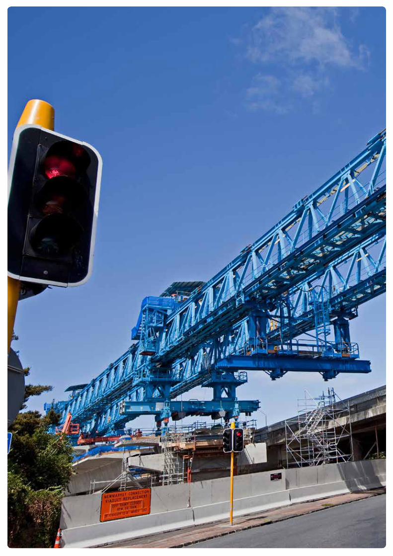

4.1 Noise calculation 42
4.2 Noise data 49
4.3 Web noise calculator 52
Case study – Newmarket Connection 54
4.4 Noise modeling 55
4.5 Vibration calculation 56
4.6 Vibration data 68
4 Predictions
4

42 NZ Transport Agency | State highway construction and maintenance noise and vibration guide | SP/M/023 | August 2013 / version 1.0
4.1 Noise calculation
For predicting construction and maintenance noise a basic calculation method is provided in NZS 6803:199906, which is copied from an old version of BS 5228. This section describes some of the key elements of the calculations. In some places the equations have been simplified and reference should be made to the 2009 version of BS 5228-1 for the full method. For calculations that are more complex than those included in the web calculator (section 4.3), an acoustics specialist will be required.
This method is usually conservative and experience on some projects is that noise levels measured on site are often several decibels lower than predicted.
Sound power and sound pressureReference data for construction and maintenance equipment and processes are given in BS 5228-1 as sound pressure levels at 10m (LP). Data quoted in other places are sometimes given in an alternative format as a sound power level (LW), often when associated with computer models. Sound power is a physical characteristic of a noise source, which results in different sound pressure levels at different distances from the source. The relationship between the two quantities is shown below.
Sound power level (quantity used in computer models)
Propagation (reference distance 10m)
Sound pressure level at 10m (quantity given in BS 5228-1)
equation LW = 20×log10(distance) + 8 + LP
example LW = 20×log10(10m) + 8 + 81
Result 109 = 28 + 81
FIGURe 4.1 Relationship between sound power and sound pressure
10m
Lp @ 10m = 81dBLw = 109dB
As can be seen above the sound power level and the sound pressure level at 10m are related by a simple equation (28dB difference). It doesn’t matter which quantity is used, providing that subsequent calculations use the corresponding version of the equations.

NZ Transport Agency | State highway construction and maintenance noise and vibration guide | SP/M/023 | August 2013 / version 1.0 43
Sound decay with distanceThe calculation method describes each item of equipment as a ‘point’ source and the sound levels decrease 6dB each time the distance from the source doubles (20×log10(distance)). Figure 4.2 shows an example of this.
FIGURe 4.2 Sound decay with distance
10m 20m 40 m 80 m 160 m
81dB 75dB 69dB 63dB 57dB
Facade levelsFor construction noise, measurements are made at a location 1m from the facade of a building. Consequently, sound is reflected off the facade and results in an increased level being measured. A 3dB facade correction is required to be included in calculations to allow for this effect (figure 4.3).
For source data in terms of the sound pressure level at 10m, the facade level at a house at 50m is calculated as follows.
FIGURe 4.3 Facade correction
Sound pressure level
Decay with distance Facade reflection
Facade level
equation LP at 10m –20×log10(distance/10) + 3 = LP at facade
example 81 –20×log10(50/10) + 3 = LP at facade
Result 81 –14 + 3 = 70
50m (–14dB) +3dB
10m
Lp @ 10m = 81dB Lp @ facade = 70dB
Multiple items of equipmentWhere there are multiple items of the same equipment, a correction is made to the noise level for one item of equipment to calculate the cumulative sound level. For example, if there were 4 items of the same equipment, one of which resulted in a facade noise level of 70dB, the cumulative sound level would be:
Facade noise level, one item of equipment
Number of sources correction
Facade noise level, all items of equipment
equation Lp@façade,source#1 + 10×log10(n) = Lp@facade,total
example 70 + 10×log10(4) = Lp@facade,total
Result 70 +6 = 76

44 NZ Transport Agency | State highway construction and maintenance noise and vibration guide | SP/M/023 | August 2013 / version 1.0
Operating periodNZS 6803:1999 requires assessment of sound levels over a representative period to account for the variable nature of construction and maintenance sound. For road construction and maintenance, 15 minutes is usually adopted, although the period can be between 10 and 60 minutes. If any specific item of equipment is not operating for the full period then the level predicted for that item of equipment is reduced (figure 4.4). This is shown in the example below, where a bulldozer is operating for only 9 minutes in the 15-minute period (60% of the time).
Percentage operating time
equipment LP Operating period correction
Corrected level
equation P LP + 10×log10(P/100) = LP2
example 60% 81 + 10×log10(60/100) = LP2
Result 81 – 2.2 = 78.8
FIGURe 4.4 Operating period correction
Sound from multiple items of different equipment is combined by summing the noise levels. Logarithmic addition is used as the noise levels are in decibels (section 1.5). For example, if 3 items of equipment produced noise levels at the facade of 76, 69 and 72, the total noise would be:
Moving sourcesBS 5228-1:2009 provides two methods for assessing noise of moving sources. One is for trucks on a haul road and the other is for slow-moving vehicles in a constrained area such as a work site. For most assessments, the overall construction noise is dominated by the noise from vehicles in a work site, rather than trucks on a haul road. Therefore, only the equation for slow-moving sources within a site is presented here.
Where there is a moving source, the BS 5228-1 data relates to the equipment at the nearest (loudest) point rather than being an average value. For slow-moving sources in a constrained area, BS 5228-1 makes allowance for the times when the equipment is further away from the houses and therefore quieter. This is done by effectively reducing the operating time.
Ope
ratin
g pe
riod
corr
ectio
n, d
B
Percentage on time, %
-10
-8
-6
-4
-2
0
10 20 30 40 50 60 70 80 90 100
Sum of facade noise level of each source Facade noise level, all items of equipment
equation 10×log10(100.1×Lp1 + 100.1×Lp2 + 100.1×Lp3) = Lptotal
example 10×log10(100.1×76 + 100.1×69 + 100.1×72) = Lptotal
Result 10×log10(6.36×10⁷) = 78

NZ Transport Agency | State highway construction and maintenance noise and vibration guide | SP/M/023 | August 2013 / version 1.0 45
The effective reduction in the operating time is related to the ratio of the distance to the noise-sensitive receiver and the distance the equipment traverses. BS 5228-1 gives correction factors for various ratios and the following equation, with the estimated constants 0.07 and 0.6, approximately fits that data. This should be capped at a value of 1 so that the effective operating time cannot exceed 100%. For a source traversing a distance of 100m, 50m from a building (figure 4.5):
FIGURe 4.5 Moving sources
The correction factor is multiplied by the actual percentage operating time to obtain the effective percentage operating time. The predicted level is then adjusted in the same manner as described above for the percentage operating time. For example, for a bulldozer operating 60% of the time, over a distance of 100m and 50m from a house at the nearest point (a distance correction is also applicable but not shown here):
effective percentage operating time
equipment LP
Correction Corrected level
equation P LP + 10×log10(P/100) = LP2
example 0.43 × 60% 81 + 10×log10(0.43×60/100) = LP2
Result 81 – 5.9 = 75.1
Distance traversed by moving equipment
Minimum distance to house
Moving source correction factor
equation ltr dmin + 0.07 + 0.6
example 100m 50m + 0.07 + 0.6(100/50)
Result = 0.43
(ltr/dmin)
50m100m

46 NZ Transport Agency | State highway construction and maintenance noise and vibration guide | SP/M/023 | August 2013 / version 1.0
BarriersBarriers and enclosures can be a useful way to prevent noise from reaching nearby buildings. As a rule-of-thumb, when a noise barrier breaks the direct line-of-sight between the source and the receiver, the noise is reduced by approximately 5dB. Increasing the height of the barrier increases the performance, with a theoretical limit of about 20dB. In practice, however, a realistic limit is about 15dB.
The accurate calculation of barrier performance is a complex process and requires the sound pressure levels at separate frequencies, in addition to the geometry of the receiver in relation to the source and the barrier. When the receiver is ‘hidden’ behind the barrier, noise from the source is attenuated. The amount of attenuation depends on the ‘path difference’. This is the difference in length between the direct line-of-sight and the distance from the source to the top of the barrier to the receiver. Higher attenuation is generally obtained with increasing path difference.
If the receiver is ‘visible’ from the source, then some attenuation occurs (less than 5dB) at small path differences. This phenomena is not important for mitigating construction noise, where significant attenuation is usually required (of the order of 10dB) and is often ignored.
A further feature of barriers is that they are more effective at reducing noise containing high frequency components than low frequency components. Therefore they may not be as useful for sources containing a high proportion of low frequency noise.
The NZTA Transport Noise web-based construction noise calculator includes a barrier module (figure 4.6). Further information on barrier performance can be obtained from Annex F of BS 5228-1:2009 and ISO 9613-2:199629.29 International Organization for
Standardization (1996) ISO 9613-2 Acoustics – Attenuation of sound during propagation outdoors – Part 2: General method of calculation. www.iso.org
FIGURe 4.6 Barrier module from NZTA Transport Noise website
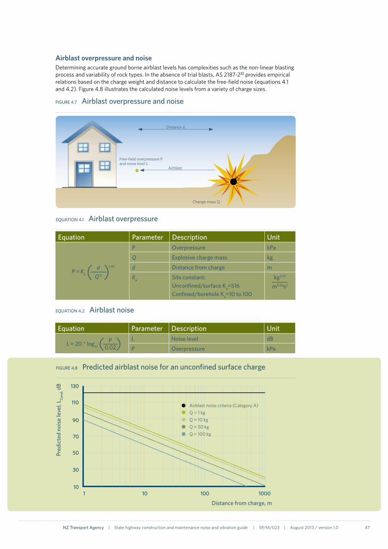
NZ Transport Agency | State highway construction and maintenance noise and vibration guide | SP/M/023 | August 2013 / version 1.0 47
Airblast overpressure and noiseDetermining accurate ground borne airblast levels has complexities such as the non-linear blasting process and variability of rock types. In the absence of trial blasts, AS 2187-222 provides empirical relations based on the charge weight and distance to calculate the free-field noise (equations 4.1 and 4.2). Figure 4.8 illustrates the calculated noise levels from a variety of charge sizes.
Airblast
Distance d
Free-field overpressure P and noise level L
Change mass Q
FIGURe 4.7 Airblast overpressure and noise
FIGURe 4.8 Predicted airblast noise for an unconfined surface charge
10
30
50
70
90
110
130
1 10 100 1000
Pred
icte
d no
ise
leve
l, L Zp
eak d
B
Distance from charge, m
Airblast noise criteria (Category A)Q = 1 kgQ = 10 kgQ = 50 kgQ = 100 kg
equation Parameter Description Unit
P = Ka
P Overpressure kPa
Q explosive charge mass kg
d Distance from charge m
Ka Site constant:Unconfined/surface Ka=516Confined/borehole Ka=10 to 100
kg2.07
m0.69s2
( )dQ⅓
-1.45
eqUATION 4.1 Airblast overpressure
equation Parameter Description Unit
L = 20 * log10
L Noise level dB
P Overpressure kPa( )P 0.02
eqUATION 4.2 Airblast noise
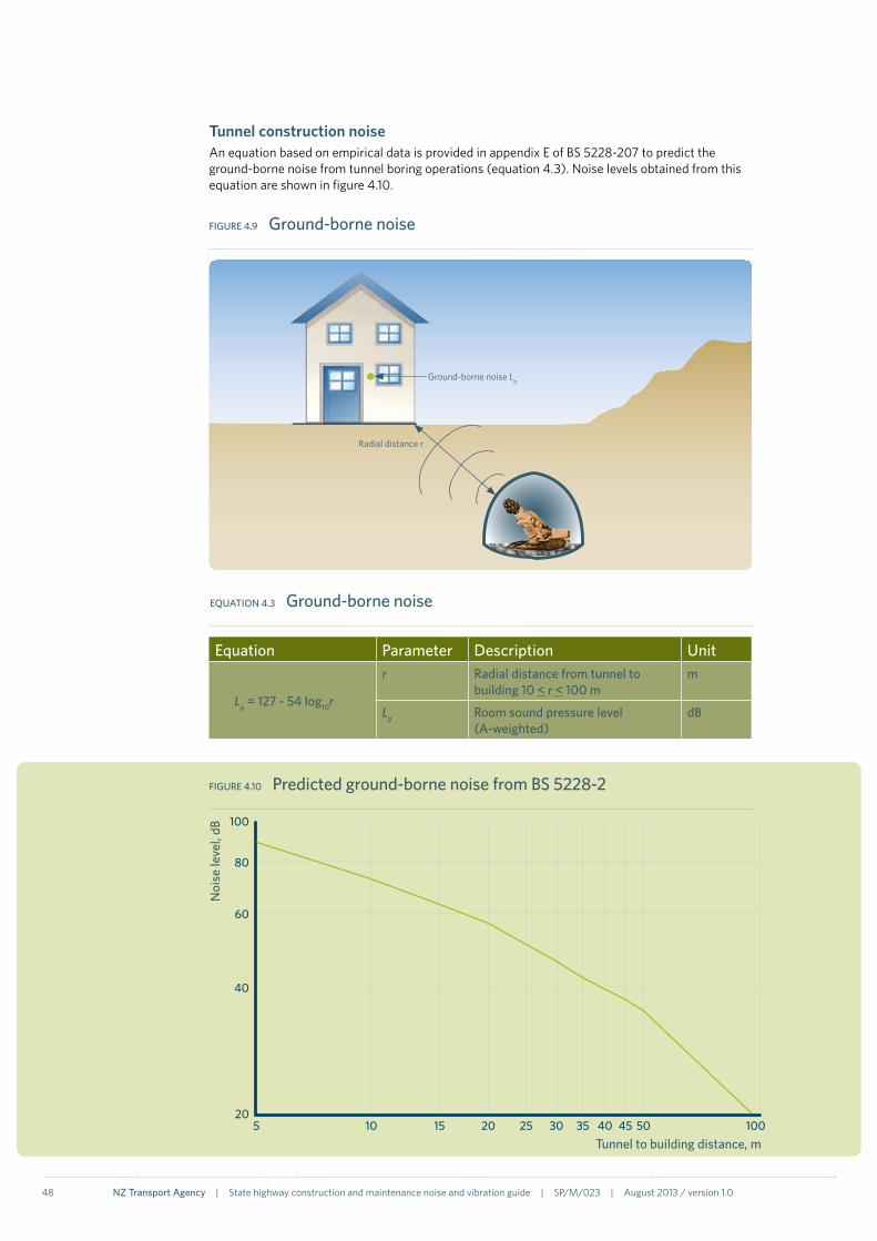
48 NZ Transport Agency | State highway construction and maintenance noise and vibration guide | SP/M/023 | August 2013 / version 1.0
Tunnel construction noise An equation based on empirical data is provided in appendix E of BS 5228-207 to predict the ground-borne noise from tunnel boring operations (equation 4.3). Noise levels obtained from this equation are shown in figure 4.10.
FIGURe 4.9 Ground-borne noise
Radial distance r
Ground-borne noise Lp
FIGURe 4.10 Predicted ground-borne noise from BS 5228-2
205
Noi
se le
vel,
dB
Tunnel to building distance, m10 15 20 25 30 35 40 45 50 100
40
60
80
100
eqUATION 4.3 Ground-borne noise
equation Parameter Description Unit
Lp = 127 - 54 log10r
r Radial distance from tunnel to building 10 < r < 100 m
m
Lp Room sound pressure level (A-weighted)
dB

NZ Transport Agency | State highway construction and maintenance noise and vibration guide | SP/M/023 | August 2013 / version 1.0 49
4.2 Noise data
Ideally, noise data in calculations should be for the specific equipment to be used on site. However, at the assessment stage the equipment has not always been selected, and often data is not available until measurements can be made when equipment arrives on site. Therefore, for initial predictions it is often necessary to use reference noise data.
BS 5228-1:2009 includes reference noise level data for typical construction equipment. These data have been obtained from measurements at construction sites in the United Kingdom on similar types of equipment to that used in New Zealand. The standard also contains historical data from an earlier version, which is reproduced in NZS 6803:1999. Where possible the more recent data should be used as it relates to current equipment types. The main BS 5228-1 data is provided in the NZTA web calculator. When using these data it should be remembered that it relates to a specific measurement of a specific item of equipment, so should only be used as a guide.
Manufacturers sometimes provide noise data for their equipment. However, this is generally only for the engine noise and not for the equipment in operation on a site. For example, manufacturers’ data would not include noise from material being dropped from a loader’s bucket. While equipment engine noise is often dominant, it is better to base predictions on actual measurements of the equipment in operation including all noise sources.
On-site measurements of the operation of the actual equipment should provide the most accurate data. These can be made using a basic sound level meter, typically with a sound pressure measurement at 10m from the equipment. A basic sound level meter does not require frequency analysis capability and can be of class 2 or higher standard. Care should be taken to ensure that the sound being measured is uncontaminated by other noise sources but includes all likely operating conditions of the equipment, in terms of both function and material being worked on. There may well be variability between nominally identical items of equipment and improved data can be obtained by repeating the measurements on other items of the same equipment if available.

50 NZ Transport Agency | State highway construction and maintenance noise and vibration guide | SP/M/023 | August 2013 / version 1.0
BS 5228 noise source levelsThe following are examples of some equipment typically used on road construction projects. Included are some typical noise levels for that type of equipment from BS 5228-1:200908, in terms of the LAeq noise level at 10m. As sound decays with distance, lower noise levels will occur at distances greater than 10m.
FIGURe 4.11 excavator
FIGURe 4.12 Grader
FIGURe 4.13 Compactor
FIGURe 4.14 Truck
Idling 52–68dB
Earthworks 69–80dB
Clearing site 70–78dB
Loading lorry 79dB
(BS 5228-1 tables C.2, C.4 and C.5)
Earthworks 78–81dB
(BS 5228-1 table C.2)
Vibrating 67–77dB
(BS 5228-1 table C.5)
Passing 80dB (LAmax)
(BS 5228-1 table C.2)

NZ Transport Agency | State highway construction and maintenance noise and vibration guide | SP/M/023 | August 2013 / version 1.0 51
FIGURe 4.15 Crane
FIGURe 4.16 Sheet piling
FIGURe 4.17 Bored piling
FIGURe 4.18 Milling
FIGURe 4.19 Paving
Mobile – idling 60–66dB
Mobile 67–82dB
Tower 76–77dB
(BS 5228-1 table C.2)
Vibratory 88dB
Hydraulic jacking 59–63dB
Hydraulic jacking 77–88dB (tubular steel)
(BS 5228-1 table C.3)
Milling 82dB
Milling – mini 68dB
(BS 5228-1 table C.5)
Asphalt paver 75–77dB
(BS 5228-1 table C.5)
Rotary bored 75–83dB
Continuous flight auger 79–80dB
(BS 5228-1 table C.3)

52 NZ Transport Agency | State highway construction and maintenance noise and vibration guide | SP/M/023 | August 2013 / version 1.0
4.3 Web noise calculator
A construction and maintenance noise calculator is included on the NZTA Transport Noise website (www.acoustics.nzta.govt.nz). This calculator provides a method for basic assessment of construction and maintenance noise, based on the NZS 6803:1999 method detailed in the previous pages. It does not currently include the prediction of vibration. The calculations are conservative and can be used for simple Tier 3 situations. The calculator is subject to the following limitations:
• The calculator should not be used where distances to PPFs exceed 200m or where there is screening other than a barrier.
Library sound level data is taken from BS 5228-1:2009:
• Moving sources are assumed to be slow and within a constrained site (eg not faster-moving trucks on haul roads).
• Air absorption, ground attenuation, meteorological effects and screening are not included in the main calculations.
• In addition to the LAeq(15 min) noise criteria in this calculator, NZS 6803 also includes separate maximum noise criteria (section 2.1). Where there are short duration or impact sounds, a separate assessment should be carried out for the maximum noise levels.
The calculator includes an option to determine noise barrier performance as an independent step that is not included in the main results.
A flowchart of the calculation process is presented in figure 4.21. The same calculator can be accessed as a stand-alone tool or as part of a ‘project’ (section 5.10). When the calculations are saved in a project the results can then be viewed and accessed by all members of the project team. Within a project, a specific library of noise data for equipment used on that project can be created and used in the calculator (figure 4.20).
FIGURe 4.20 equipment selection

NZ Transport Agency | State highway construction and maintenance noise and vibration guide | SP/M/023 | August 2013 / version 1.0 53
FIGURe 4.21 Construction and maintenance noise calculator process
Select project noise criteria
Save noise sources table as initial ‘Project Equipment List’
Review noise criteria for construction activity
Determine closest receiver for applicable worksite and activity
Press calculate and compare with noise criteria
Select project equipment to be used, including quantity and duty
Design barrier if required
Enter location and activity detail and save calculation to the project
yes
No
CON
STRU
CTIO
N C
ALC
ULA
TOR
PRO
jeCT
SyS
TeM
PRO
jeCT
SyS
TeM
Try alternative equipment, quantity and duty
Are noise criteria met?

54 NZ Transport Agency | State highway construction and maintenance noise and vibration guide | SP/M/023 | August 2013 / version 1.0
Case study – Newmarket Connection, Auckland (2008–2012)The Newmarket Connection project is a four-stage replacement of the Newmarket Viaduct (motorway flyover), with a wider, stronger, more sustainable new structure. The project also aims to improve pedestrian links around Newmarket. The project is being delivered by the NGA Newmarket Alliance, comprising the NZTA, Fulton Hogan, Leighton Contractors, VSL NZ, Beca, URS, Tonkin & Taylor and Boffa Miskell.
Construction noise criteria for the viaduct replacement were specified within the designation conditions for compliance with NZS 6803:1999 at residential properties as close as 20m to the works30. Following construction noise complaints received early in the project, additional noise management procedures were instigated, including use of the NZTA Transport Noise web calculator.
‘A key strategy to achieve consistency in noise management for the project was to use tools and information that were readily available, and version controlled,’ stated Simon Paton of the NGA Newmarket Alliance. To meet these objectives, the project used the NZTA website to act as a portal for all relevant noise-related information, particularly the construction noise calculator.
For the majority of the construction equipment used on the project, noise data was measured to provide inputs to the website construction noise calculator. Table 4.1 presents the sound pressure level at 10m for various construction equipment and activities. These noise data may be useful for initial assessments on other projects where library data from BS 5228-1 is not representative of certain equipment.
FIGURe 4.22 Project schematic
St Marks Rd
4th lane southbound
St Marks Rd on-ramp realignment
Realignment of northbound carriageway
New southbound bridgeGillies Ave Bridge
– southbound
Gillies Ave Bridge – northbound
Gillies Ave off-ramp realignment
Widening of new northbound bridge (after deconstruction of existing northbound bridge)
Mt Hobson Rd noise wall
Dilworth pedestrian bridge
30 Northern Gateway Alliance (2008) Newmarket Viaduct Project Construction Noise and Vibration Management Plan. www.nzta.govt.nz
equipment/activity Sound pressure level at 10m (dB)
equipment/activity Sound pressure level at 10m (dB)
Asphalt paver 60-68 Generator 55-71Bobcat S185 61 Hiab 82Chainsaw 96 Loader 74Chainsaw - electric 77 Miling machine 75Cherry picker 69-79 Piling 79-80Circular saw 81 Power pack 74Concrete pour/pump 70-75 Reversing alarm 73-75Crane 49-82 Rockbreaker 79-91Drilling 66-92 Scissor jack 66Drum roller 62-79 Streetsweeper 67-83Dynapac PC/32 61 Wall saw 81-84excavator 70-81 Water blasting 75-94Franner 74 Wire saw 71-75
TABLe 4.1 Measured noise source data from Newmarket Connection project
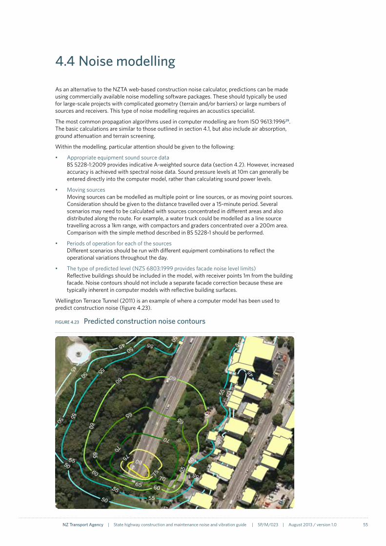
NZ Transport Agency | State highway construction and maintenance noise and vibration guide | SP/M/023 | August 2013 / version 1.0 55
4.4 Noise modelling
As an alternative to the NZTA web-based construction noise calculator, predictions can be made using commercially available noise modelling software packages. These should typically be used for large-scale projects with complicated geometry (terrain and/or barriers) or large numbers of sources and receivers. This type of noise modelling requires an acoustics specialist.
The most common propagation algorithms used in computer modelling are from ISO 9613:199629. The basic calculations are similar to those outlined in section 4.1, but also include air absorption, ground attenuation and terrain screening.
Within the modelling, particular attention should be given to the following:
• Appropriate equipment sound source data BS 5228-1:2009 provides indicative A-weighted source data (section 4.2). However, increased accuracy is achieved with spectral noise data. Sound pressure levels at 10m can generally be entered directly into the computer model, rather than calculating sound power levels.
• Moving sources Moving sources can be modelled as multiple point or line sources, or as moving point sources. Consideration should be given to the distance travelled over a 15-minute period. Several scenarios may need to be calculated with sources concentrated in different areas and also distributed along the route. For example, a water truck could be modelled as a line source travelling across a 1km range, with compactors and graders concentrated over a 200m area. Comparison with the simple method described in BS 5228-1 should be performed.
• Periods of operation for each of the sources Different scenarios should be run with different equipment combinations to reflect the operational variations throughout the day.
• The type of predicted level (NZS 6803:1999 provides facade noise level limits) Reflective buildings should be included in the model, with receiver points 1m from the building facade. Noise contours should not include a separate facade correction because these are typically inherent in computer models with reflective building surfaces.
Wellington Terrace Tunnel (2011) is an example of where a computer model has been used to predict construction noise (figure 4.23).
FIGURe 4.23 Predicted construction noise contours

56 NZ Transport Agency | State highway construction and maintenance noise and vibration guide | SP/M/023 | August 2013 / version 1.0
4.5 Vibration calculation
In comparison to the prediction of noise, calculating vibration levels is more complex. This is primarily due to the propagation though non-uniform ground plus the coupling between the vibration source and the ground; and between the ground and the building. Because of these factors, vibration results are generally less accurate than those obtained when predicting noise.
Because of the dependence of the level of vibration to local ground conditions, the most accurate method to determine the vibration levels is to undertake a trial using the appropriate equipment at the site. Without such a trial, calculations can be made in advance of the works and confirmed at the start of the works by measurements near to or on any at-risk locations.
A variety of different calculation methods have been developed for construction vibration31. To evaluate the most appropriate for this guide, preference has been given to the methods that contain a site specific assessment of the vibration propagation through the ground, either by measurement or by classification of the soil type, thereby minimising the significant factor in the source to receiver path. The result of this evaluation is summarised in figure 4.24.
The selected calculation methods are described in the following pages:
Method A – Blasting calculation methods from AS 2187-2.
Method B – Piling or compaction methods, combining calculated source data with measured propagation data.
Method C – Empirical equations from BS 5228-2.
Method D - Measured source data combined with a distance correction.
All of these methods predict the vibration on the surface of the ground (known as the ‘free-field’ vibration). However, the assessment of annoyance and building damage require vibration to be assessed inside the property and on the foundation respectively. Hence, calculation methods to account for the coupling between the ground and the building floor/foundation are described on page 59.
Sensitive PPFs may require more detailed, frequency-dependent assessments which are outside the scope of this guide.
31 NZ Transport Agency (2012) Ground vibration from road construction, research report 485. www.nzta.govt.nz
Research report 485The NZTA research report 485 on ground vibration summarises a programme of research that commenced in 2005 with the scope of quantifying the levels of ground borne vibration generated during various road construction activities and their attenuation with distance for different New Zealand soil types. The principal objective of the research was to develop a desk-based methodology, validated for New Zealand conditions, for determining separation distances for construction activities to ensure minimal effect on structures and their occupants.
The research involved the following:
1. A literature review concentrating on the fundamental theory of ground-borne vibrations; measured vibration levels for different types of construction equipment; criteria for assessing vibration levels; and calculation methods.
2. Measurement and analysis of ground-borne vibration data from construction sites throughout New Zealand for representative mechanised construction plant operating on a range of soil types.
3. Investigation into the use of commonly measured geotechnical data (scala penetrometer and falling weight deflectometer) as inputs into the calculation methods.
The results from this report have been included throughout this guide.
In the research report, the measured vibration data is presented as the ‘square-root of the sum of squares’ (SRSS), otherwise known as the pseudo, or simulated resultant, and is the vector addition of the maximum level of each direction regardless of the time it occurs. Thus this level of vibration will never occur and assessments based on these data will be over-estimates and therefore conservative.

NZ Transport Agency | State highway construction and maintenance noise and vibration guide | SP/M/023 | August 2013 / version 1.0 57
No
yes Method A
No
No
yes FWD data avaliable?
yes Method B
Method C
No
yes Method D
yes
No
Undertake trial works and measure vibration (section 5.9)
yes
No
Method C
Method D with BS 5228-2 source data
Calculate foundation internal levels if required (page 59)
FIGURe 4.24 Selection of vibration calculation method
Blasting works?
Piling or compaction works?
Tunnel boring or
vibration of stone columns?
Site preparation works?
Are trial
measurements possible?

58 NZ Transport Agency | State highway construction and maintenance noise and vibration guide | SP/M/023 | August 2013 / version 1.0
Method A - Blasting vibration In the absence of trial blasts, AS 2187-222 provides an empirical relation based on the charge weight and distance to calculate the free-field ground borne vibration (equation 4.4). Figure 4.26 illustrates the calculated vibration levels from a variety of charge sizes.
FIGURe 4.25 Blast vibration
FIGURe 4.26 Predicted vibration from blasting
0.01
0.1
1
10
100
1 10 100 1000Pred
icte
d vi
brat
ion
leve
l, re
sulta
nt p
pv m
m/s
Distance from charge, m
Building damage criteria (Category A) Daytime annoyance criteria (Catergory A)Q = 1 kgQ = 10 kgQ = 50 kgQ = 100 kg
equation Parameter Description Unitppvres Resultant ppv mm/s
Q explosive charge mass kg
d Distance from charge m( )dQ½
-1.6
ppvres = 1140
eqUATION 4.4 Ground vibration from blasting
Distance d
Free-field vibration level ppv
Change mass Q
Ground borne vibration

NZ Transport Agency | State highway construction and maintenance noise and vibration guide | SP/M/023 | August 2013 / version 1.0 59
Foundation and building responseOnce the free-field vibration is known, it is often necessary to calculate the vibration levels on building foundations and floors in order to assess building damage and annoyance (section 2.2). The propagation of vibration from the ground to the building structure depends on many factors, including the coupling between the ground and the foundation; plus the design of the foundations, floors, walls and ceilings and structure.
Generally there is a reduction in vibration from the ground to the foundation and then a further decrease from the foundation into the remainder of the building. However, resonances in floors can lead to an increase, especially in wood-frame residential structures but also in reinforced concrete slab floors.
Frequency-dependent functions relating the free-field vibration to the foundation and floor vibration have previously been determined32 and these are simplified as frequency-independent factors in table 4.2. and table 4.3. The variety in foundation designs has led to a range of factors and these factors can be applied directly to the free-field ppv levels. An example calculation is shown in table 4.4.
TABLe 4.2 Foundation response
Foundation type Factor of vibration on foundation relative to free-field vibration
Slab on grade 1
Single family residential 0.56 to 1
1 and 2 storey residential 0.35 to 0.79
2 to 4 storey masonry building on spread footings 0.22 to 0.56
Large masonry building on piles 0.2 to 0.56
Large masonry building on spread footings 0.2 to 0.32
TABLe 4.3 Floor response
Type Factor
Vibration on floor relative to foundation vibration 0.79 to 0.89 per storey
Vibration on floor relative to floor vibration, due to resonance of wooden or concrete slab floor
2
32 US DOT/Transportation Systems Center (1982) Handbook of Urban Rail Noise and Vibration Control, Report UMTA-MA-06-0099-82-2. www.hmmh.com
TABLe 4.4 example calculation
Location Factor ppv (mm/s)
Free-field vibration level - 1.5
Foundation of 2 storey residential building
0.35 to 0.79 0.5 to 1.2
2nd storey floor 0.79 to 0.89 per floor =1.58 to 1.78
0.8 to 2.1
Wooden floor resonance 2 1.6 to 4.2

60 NZ Transport Agency | State highway construction and maintenance noise and vibration guide | SP/M/023 | August 2013 / version 1.0
Method B - Falling weight deflectometer dataThis method combines predicted energy input into the ground from the equipment with measured propagation through the soil, the latter obtained using a ‘falling weight deflectometer’ (FWD). Detailed knowledge of the site geology is not required as the soil attenuation characteristics are captured in the measured propagation.
A FWD imparts a load onto the ground by dropping a large weight onto a circular load plate. A load cell mounted on top of the load plate measures the load imparted to the ground and a number of sensors (usually geophones), mounted radially from the load plate, measure the deformation of the ground in response to the load. The NZTA has a comprehensive collection of FWD measurements over the state highway network which are logged in the Road Assessment and Management (RAMM) database. This database does not contain the time history FWD data required by this method but this can be supplied by the NZTA on request.
The propagation through the ground is determined from the FWD data by:
1. Calculating the ppv from each of the FWD sensors. For road pavement studies, the FWD data is typically obtained as displacements and therefore the ppv should be obtained from the velocity time histories by differentiating the displacement time history.
2. The scaled distance of each of the sensors is calculated using:
FIGURe 4.27 Falling weight deflectometer
equation Parameter Description UnitSD Scaled distance m/j0.5
d Distance from load plate to sensor m
W energy imparted by the FWD j
SD = d
W
eqUATION 4.5 Scaled distance

NZ Transport Agency | State highway construction and maintenance noise and vibration guide | SP/M/023 | August 2013 / version 1.0 61
3. The scaled distances are plotted against the ppv on a log-log plot and a non-linear regression line is fitted to the data of the form:
4. A 95% confidence interval is applied to the regression constant b to ensure a conservative prediction:
From this propagation characteristic, the ground vibration at a receiver can be calculated from the energy input into the ground by the works:
5. The predicted energy input into the ground for vibratory compaction is:
6. Alternatively, the predicted energy input into the ground for impact piling can be calculated using equation 4.6.
7. The scaled distance is calculated using equation 4.5, using the energy input W from step 5 or 6 and the distance d between the source and the receiver.
8. The ppv is calculated using the scaled distance from step 7 using equation 4.8.
equation Parameter Description UnitW energy imparted by the FWD j
m Drop mass kg
g Acceleration due to gravity (9.81) m/s2
h Drop height m
W = mgh
eqUATION 4.6 FWD energy
equation Parameter Description Unitb Regression constant -
SD Scaled distance m/j0.5
m Regression constant -
ppv = b(SD)m
eqUATION 4.7 Regression line
equation Parameter Description Unitb Regression constant -
SD Scaled distance m/j0.5
m Regression constant -
SE Standard error of the estimation mm/s
ppv = (b + 1.96SE)(SD)m
eqUATION 4.8 Regression line with 95% confidence
equation Parameter Description UnitW energy of compactor j
D Drum diameter m
n Number of blows per unit distance -
P Peak load N
A Peak amplitude m
W = DnPA
eqUATION 4.9 Vibratory compaction energy

62 NZ Transport Agency | State highway construction and maintenance noise and vibration guide | SP/M/023 | August 2013 / version 1.0
Step
Des
crip
tion
Para
met
erVa
riabl
eU
nit
Valu
e(s)
1Ca
lcul
ate
the
ppv
for e
ach
of
the
FWD
se
nsor
s
Tim
e hi
stor
y of
FW
D d
ispl
acem
ent d
ata
t; x
s; μ
m
Displacement, μm 140
160
120
100 80 60 40 20 0
-20
-40
00.
020.
040.
060.
080.
10.
12Ti
me,
s
Forc
e-Re
spon
se d
ista
nce
0.75
m0.
9m1.2
m1.5
m
0.2m
0.3m
0.45
m0.
6m
Tim
e hi
stor
y of
vel
ocity
by
diffe
rent
iatio
n of
di
spla
cem
ent d
ata
t; x
s; m
m/s
Velocity, mm/s
12 8 4 0 -4 -80
0.02
0.04
0.06
0.08
0.1
0.12
Tim
e, s
10 6 2 -2 -6
0.2m
0.3m
0.45
m0.
6m
Forc
e-Re
spon
se d
ista
nce
0.75
m0.
9m1.2
m1.5
m
Dis
tanc
e fr
om lo
ad p
late
dm
0.2
0.3
0.45
0.6
0.75
0.9
1.21.5
Peak
par
ticle
vel
ocity
ppv
mm
/s10
.49.
88.
47.
26.
25.
44.
23.
42
Calc
ulat
e sc
aled
di
stan
ces
Dro
p m
ass
mkg
4000
Acc
eler
atio
n du
e to
gra
vity
gm
/s2
9.81
Dro
p he
ight
hm
0.5
ener
gy im
part
ed b
y th
e FW
D (e
quat
ion
4.6)
Wj
1962
0D
ista
nce
from
load
pla
ted
m0.
20.
30.
450.
60.
750.
91.2
1.5Sc
aled
dis
tanc
e (e
quat
ion
4.5)
SDm
/j0.
50.
001
0.00
20.
003
0.00
40.
005
0.00
60.
009
0.01
13
Regr
essi
on li
neRe
gres
sion
con
stan
tm
mm
/s/m
-0.5
6Re
gres
sion
con
stan
tb
mm
/s0.
3
TABL
e 4.
5 e
xam
ple
– M
etho
d B
pred
ictio
n us
ing
FWD
dat
a
.

NZ Transport Agency | State highway construction and maintenance noise and vibration guide | SP/M/023 | August 2013 / version 1.0 63
Step
Des
crip
tion
Para
met
erVa
riabl
eU
nit
Valu
e(s)
495
% c
onfid
ence
Stan
dard
err
orSE
0.84
Scal
ed d
ista
nce
SDm
/j0.
50.
001
0.00
20.
003
0.00
40.
005
0.00
60.
009
0.01
1pp
v w
ith 9
5% c
onfid
ence
inte
rval
(e
quat
ion
4.8)
ppv
mm
/s2
77.8
62.0
49.3
42.0
37.0
33.4
28.4
25.1
0.00
10.
010
ppv, mm/s100 10 1
Scal
ed d
ista
nce,
m/j
0.5
y =
3.12
x-0.5
6
R2 = 0
.94
FWD
ppv
95%
con
fiden
ce p
pv
6Pr
edic
ted
ener
gy
into
the
grou
nd
for i
mpa
ct p
iling
Dro
p m
ass
mpi
ling
kg50
00D
rop
heig
hth pi
ling
m3.
0en
ergy
(equ
atio
n 4.
6)W
pilin
gj
1471
507
Scal
ed d
ista
nce
for p
iling
wor
kD
ista
nce
to p
iling
wor
kd pi
ling
m2
510
1520
2530
50
Scal
ed d
ista
nce
of im
pact
pili
ng (e
quat
ion
4.5)
SDpi
ling
m0.
010.
010.
030.
040.
050.
070.
080.
13
8Pr
edic
ted
vibr
atio
npp
v (e
quat
ion
4.8)
ppv pi
ling
mm
/s37
.622
.515
.212
.110
.39.
18.
26.
2
ppv, mm/s
3035 25 20 15 10 5 00
1020
3040
50D
ista
nce,
m
Pred
icte
d vi
brat
ion
from
im
pact
pili
ng w
orks

64 NZ Transport Agency | State highway construction and maintenance noise and vibration guide | SP/M/023 | August 2013 / version 1.0
Method C – BS 5228-2 equationsEquations based on empirical data are provided in appendix E of BS 5228-207 to predict vibration from vibratory dynamic compaction; percussive and vibratory piling; the vibration of stone columns and tunnel boring operations. Note that these methods calculate the resultant ppv (section 1.6). For some of the construction methods, the results are in terms of the probability of the predicted ppv levels being exceeded. The equations are reproduced in table 4.6 and the predicted levels are shown in figure 4.29.
FIGURe 4.28 Compaction, piling and tunnel boring
Distance d
Free-field vibration ppv
FIGURe 4.29 Predicted vibration from BS 5228-2
0
0.1
1
10
100
1000
10000
65 7 8 9 10 20 30 40 50 60 70 80 90 100
Resu
ltant
ppv
, mm
/s
Distance, m
Dynamic compactionPercussive pilingTunnellingVibratory pilingVibratory compaction (steady state)Vibrated stone columns
Radial distance r

NZ Transport Agency | State highway construction and maintenance noise and vibration guide | SP/M/023 | August 2013 / version 1.0 65
TABLe 4.6 empirical relationships from BS 5228-2
Operation equation Scaling factors
Probability of predicted value being exceeded
Parameter range
Vibration compaction (steady state) ppvres = ks nd
ks = 75 50%
1 ≤ nd ≤ 2 0.4 ≤ A ≤ 1.72mm2 ≤ d ≤ 110m 0.75 ≤ wd ≤ 2.2m
ks = 143 33.3%
ks = 276 5%
Vibration compaction (start up and run down) ppvres = kt nd
kt = 65 50%
kt = 106 33.3%
kt = 177 5%
Percussive pilingppvres ≤ kp
Depends on soil type, table 4.7
- 0.75 ≤ l ≤ 27m1 ≤ r ≤ 111m (where r2=l2+d2)
1.5 ≤ W ≤ 85kj
Vibratory piling
ppvres =
kv = 60 50% 1 ≤ d ≤ 100m
1.2 ≤ W ≤ 10.7kj
δ = 1.3 (all operations)
δ = 1.2 (start up and run down)
δ = 1.4 (steady state operation)
kv = 126 33.3%
kv = 266 5.%
Dynamic compactionppvres ≤ 0.037
- - 5 ≤ d ≤ 100m
1.0 ≤ Wh ≤ 12Mj
Vibrated stone columnsppvres =
kc = 33 50%
8 ≤ d ≤ 100mkc = 44 33.3%
kc = 95 5%
Tunnelling (tunnel boring machine or roadheader) ppvres ≤
- -10 ≤ d ≤ 100m
ppvres – resultant ppv (mm/s)d – distance measured along ground surface (m)r – slope distance from the pile toe (m) where r2=l2+d2
l – pile toe depth (m)
A – maximum amplitude of drum (mm)wd – vibration roller drum width (m)nd – number of rotating drumsks & kv & kc – scaling factorskp – scaling factor (table 4.7)
W – nominal hammer energy (j)Wc – energy per cycle (kj)Wh – potential energy of a raised damper (j)
( )Ad + wd
1.5
( )A1.5
(d + wd)1.3
( )Wr1.3
kv
dδ
180d1.3
kc
d1.4
( )Wh
d
1.7
TABLe 4.7 Values of kp for use in the predicitions of vibration from percussive piling
Piling technique Attenuation category (refer to table 4.8) kp
Piles driven to refusal I, II, III, IV 5
Pile toe being driven through III Plus fill with large obstructions compared to pile cross-section
3
I and II 1
Pile toe not being driven through I, II, III, IV 1.5

66 NZ Transport Agency | State highway construction and maintenance noise and vibration guide | SP/M/023 | August 2013 / version 1.0
Method D – Distance corrected measured data In this method, data measured from the same construction activity at another location/project may be used. Corrections to these data should be made to account for any changes in distance, ground condition etc. BS 5228-2 provides a large amount of measured data from the UK for this purpose, from a variety of construction equipment but does not suggest a distance correction.
For equipment associated with site preparation i.e. excavation, levelling, trenching and compaction of fill, specific data for New Zealand is available in terms of the vibration levels at 10m (page 65). The distance correction is based on the soil attenuation coefficient α which can either be calculated from scala penetrometer results (equation 4.10) or determined from the soil classification in table 4.8. The coefficient is quoted at the dominant frequency (αf) or normalised to 5Hz (α5) using equation 4.11. The soil classifications are broad and will depend on site conditions and the mode of formation of the ground.
From the soil attenuation coefficient, the vibration data at 10m can be corrected using equation 4.12. For reference, the vibration levels from three different items of equipment have been calculated at a range of distances using the measured source data in page 65 for the four attenuation categories in table 4.8 and are presented in figures 4.30 to 4.32.
equation Parameter Description Unit
α5 = 0.0364e-0.411S
α5 soil attenuation coefficient at 5 Hz
1/m
S average Scala penetrometer reading
blows/100mm
eqUATION 4.10 Soil attenuation coefficient at 5 Hz from Scala penetrometer results
equation Parameter Description Unit
αf = f
αf soil attenuation coefficient 1/m
α5 soil attenuation coefficient at 5 Hz
1/m
S average Scala penetrometer reading
blows/100mm
f dominant frequency of vibration from equipment
Hz
α5
5
eqUATION 4.11 Soil attenuation coefficient from coefficient at 5 Hz
equation Parameter Description Unit
ppv2 = ppv1 e-α
(d-10)
αf soil attenuation coefficient 1/m
ppv1 peak particle velocity at 10m mm/s
ppv2 peak particle velocity at distance r
mm/s
d distance from vibration source m
( )10d
0.5
f
eqUATION 4.12 Vibration at distance

NZ Transport Agency | State highway construction and maintenance noise and vibration guide | SP/M/023 | August 2013 / version 1.0 67
FIGURe 4.30 Predicted vibration from a Komatsu D65e dozer
Note – these predictions have been made using the source data at 10m as presented on page 69. However, some of these data have been measured at distances less than 10m31 and subsequently corrected for distance. Using the 10m source data generally results in an over-prediction of the vibration level at distances less than 50m compared to using the original source data at the closer distance. This method has been used however, to provide consistency between the presented source data and the prediction method. These curves differ from those presented in the research report which uses the measured source data at the actual measurement distance.
FIGURe 4.31 Predicted vibration from a Sumitomo SH120 excavator
FIGURe 4.32 Predicted vibration from a Hamm 3410 roller
Dozer on attenuation category 1 groundDozer on attenuation category 2 groundDozer on attenuation category 3 groundDozer on attenuation category 4 ground
Cosmetic damage category A criteria
Daytime dwelling Catergory A criterion
ppv,
mm
/s
0
1
2
3
4
5
6
7
8
9
10
Distance, m0 10 20 30 40 50 60 70 80 90 100
Source: Research report 48531
Source: Research report 48531
Source: Research report 48531
Excavator on attenuation category 1 groundExcavator on attenuation category 2 groundExcavator on attenuation category 3 groundExcavator on attenuation category 4 ground
Cosmetic damage category A criteria
ppv,
mm
/s
0
1
2
3
4
5
6
7
8
9
10
Distance, m0 10 20 30 40 50 60 70 80 90 100
Daytime dwelling Catergory A criterion
Roller on attenuation category 1 groundRoller on attenuation category 2 groundRoller on attenuation category 3 groundRoller on attenuation category 4 ground
Cosmetic damage category A criteria
ppv,
mm
/s
0
1
2
3
4
5
6
7
8
9
10
Distance, m0 10 20 30 40 50 60 70 80 90 100
Daytime dwelling Catergory A criterion

68 NZ Transport Agency | State highway construction and maintenance noise and vibration guide | SP/M/023 | August 2013 / version 1.0
4.6 Vibration data
On the facing page are examples of some equipment typically used on road construction and maintenance projects, with measured vibration levels in terms of the resultant ppv at 10m31, together with the attenuation coefficient and the dominant frequency of the vibration which were also determined from the measurements (see section 4.5).
The data shows the variability in the vibration levels within a plant type, due to make and model; plus due the soil on which they are working.
TABLe 4.8 Soil attenuation coefficients
Soil classification Attenuation category
Average Scala penetrometer readingS (blows/100mm)
Soil attenuation coefficientαf (1/m)
Weak or soft soils (soil penetrates easily); lossy soils, dry or partially saturated peat and muck, mud, loose beach sand and dune sand, recently ploughed ground, soft spongy forest or jungle floor, organic soils, topsoil
I 0.2 - 3.1 0.01 - 0.033
Competent soils (can dig with shovel): most sands, sandy clays, silty clays, gravel, silts, weathered rock
II 3.1 - 6.1 0.003 - 0.01
Hard soils (cannot dig with shovel, must use pick to break up): dense compacted sand, dry consolidated clay, consolidated glacial till, some exposed rock
III 6.1 - 11.7 0.0003 - 0.003
Hard, competent rock (difficult to break with hammer): bedrock, freshly exposed hard rock
IV >11.7 <0.0003
The soil classifications in this table originate from Dowding16 and provide a straightforward method of assessing soil type through a qualitative description of consistency and hardness. The New Zealand Soil Classification provides a more detailed system which requires knowledge of the process of the soil formation. For simplicity, a relationship between the two classifications has not been attempted.

NZ Transport Agency | State highway construction and maintenance noise and vibration guide | SP/M/023 | August 2013 / version 1.0 69
Plant type Item Weight (tonne)
Soil description
Attenuation coefficient αf (1/m)
Dominant frequency f (Hz)
Resultant ppv1 at 10m (mm/s)
Doz
er
Komatsu DP31P 7.3 Pumice fill 0.031 12 3.8
Caterpillar D4H 7.9 Peat 0.073 12 11.9
Komatsu D65e 20.3 Silty sand 0.009 14 3.8
exca
vato
r Komatsu PC60 6.0 Ash - 21 1.8
Sumitomo SH120
12.6 Pumice fill 0.061 20 5.4
Gra
der
Volvo G726B 16.0 Pumice sand - 43 0.9
Rolle
r
Sakai SW500 4.0 Pumice fill 0.193 50 2.9
Sakai SW70C 7.1 Dune sand 0.016 53 0.4
Sakai SW70C 7.1 Silt 0.037 53 0.4
Bomag BW177D3
7.2 Peat 0.073 28 0.8
Dynapac CC422HF
10.4 Greywacke fill
0.088 64 1.1
Caterpillar CB544
10.7 Sandstone 0.07 40 1.1
Hamm 3410 11.0 Silty sand 0.029 29 7
Hamm 3414 14.3 Pumice sand 0.012 37 9
Caterpillar CP663e
16.8 Sandy clay 0.158 28 3.6
Caterpillar CS663e
17.1 Sandstone 0.012 26 1.8
Dynapac CA602 18.6 Sandstone 0.046 28 12.4
Caterpillar 815B 20.8 Sandstone 0.025 13 1.9
Caterpillar 825C 32.7 Sandstone 0.009 13 0.7
Stab
ilise
r
Wirtgen WR2000
22.0 Pumice sand - 36 0.9
Truc
k
- - Volcanic / sandy loam
0.018 23 -
Note 1: Resultant ppv in terms of the ‘square-root of the sum of squares’

5 Management
55.1 Plans and schedules 72
5.2 Communications 73
5.3 Mitigation 74
Case study - Vibration 76
Case study – Tile cutting booth 76
Case study – Victoria Park Tunnel and 77 Newmarket Viaduct
5.4 Training 78
5.5 Condition surveys 78
5.6 Night works 79
5.7 Diversions 80
Case study – Terrace Tunnel 81
5.8 Complaints 82
Case study – Newmarket Connection 82
Case study – Waterview noise 83 assessment/mitigation response
5.9 Monitoring 84
5.10 Documentation 87
Case study - VPT vibration measurements 90

72 NZ Transport Agency | State highway construction and maintenance noise and vibration guide | SP/M/023 | August 2013 / version 1.0
5.1 Plans and schedules
The most effective method to control construction and maintenance noise and vibration is through proactive management. This includes assessment of all activities and consideration of potential noise and vibration effects and appropriate mitigation.
To ensure that this occurs for all works with a high risk of adverse impact, the NZTA includes a management component within the designation conditions for construction projects (section 2.5) or a self-imposed requirement in the contractor procedures manual SM02133 for either construction projects or maintenance works. This is implemented in management plans and the noise and vibration component is commonly called a Construction Noise and Vibration Management Plan (CNVMP) (section 5.10). For low and medium risk construction projects and maintenance works the noise and vibration component can be a subsection of a wider Social and Environmental Management Plan (SEMP) rather than being a standalone document.
During the initial planning of works it might not be practical to make a detailed assessment for all high risk activities or locations. In that instance Construction Noise and Vibration Management Schedules (CNVMSs), sometimes referred to as ’job noise analyses’ or ‘site specific plans’, detailing the assessment for high risk specific activities or locations, may be added to the CNVMP at a later stage but still prior to each element of work starting.
For maintenance works, there should be a single CNVMP for the maintenance contract as a whole, with specific schedules for the locations and types of works, as required. A CNMVS is important even for short duration works and works where physical mitigation is known not to be practicable, as it will highlight the need for enhanced communications.
FIGURe 5.1 Key documents in the management of construction and maintenance noise and vibration
Construction/maintenance management plan
Quality plan Health and safety plan Other plans
Construction noise and vibration management plan
Construction noise and vibration management schedule 1
Construction noise and vibration management schedule 2
Other sub-plans (eg ecology, dust)
Social and Environmental Management Plan
33 NZ Transport Agency (2010) Contract procedures manual (SM021), issue 1. www.nzta.govt.nz

NZ Transport Agency | State highway construction and maintenance noise and vibration guide | SP/M/023 | August 2013 / version 1.0 73
34 NZ Transport Agency (2008) Public engagement policy and guidelines document, working draft. www.nzta.govt.nz
5.2 Communications
Effective stakeholder engagement is a critical part of managing construction and maintenance noise and vibration. Stakeholder engagement can have a greater bearing on acceptance of the works and complaints than the actual noise and vibration levels. Neighbours who understand what, when and why the works are happening are often able to adjust their activities accordingly and are generally more tolerant of construction noise and vibration. Also, where practicable, works should be scheduled to avoid noisy or vibration producing activities at any specific times identified as particularly sensitive through stakeholder engagement, accepting there is a balance between avoidance of sensitive times and the overall duration of the works. Examples include school exams or community events.
As a key stakeholder, liaising and collaborating with the territorial local authorities (TLA) is important.
Stakeholder engagement for construction and maintenance noise and vibration should be integrated with the wider project requirements, following the project communications plan and the NZTA’s Public engagement manual34. In general, neighbours should be informed at least one week before work starts and any local issues should be identified. For larger projects, stakeholder engagement should commence during the planning stages. Residents can be informed about work using a variety of means, including personal visits, letter drops, community meetings, newspaper and radio advertising, site signboards, posters and notices on websites. Where work continues for long periods, regular updates are important.
Information provided should include the:
• reasonfortheworks• reasonfortheconstructionmethodologyproposed• overalltimeframeandtimingofspecificnoisyorvibrationproducingactivities• reasonforanynightorweekendworks• expectednoiseand/orvibrationeffects.
All communications should include contact names and phone numbers. In particular:
• thenameandphonenumberofanNZTAstaffmember• thenameandphonenumberofapersonlocatedontheconstructionsitewhoisabletotake
immediate action.
Examples of flyers and letter drops are provided on the NZTA Transport Noise website for:
• nightworks• constructionactivities• roadclosure• publicbriefings/meetings.
FIGURe 5.2 Flyer examples

74 NZ Transport Agency | State highway construction and maintenance noise and vibration guide | SP/M/023 | August 2013 / version 1.0
5.3 Mitigation
Mitigation measures should be properly planned and implemented in a structured hierarchy depending on the extent of predicted effects. In general, the hierarchy should be in the order of:
• managing times of activities to avoid night works and other sensitive times• liaising with neighbours so they can work around specific activities• selecting equipment and methodologies to restrict noise• using screening/enclosure/barriers• offering neighbours temporary relocation• for long duration works, treating neighbouring buildings.
Staff• Include construction and maintenance noise management as part of site induction
procedures.• Implement an incentive scheme to prevent shouting and swearing.• Communicate using the radio/phone. • Require all staff to read the Construction Noise and Vibration Management Schedule
(CNVMS) for each particular task.• Hold regular toolbox/tailgate noise management briefings.
Equipment• Adopt quieter techniques and processes.• Select low-noise equipment. • Only use required power and size of equipment. • Fit engine exhausts with silencers.• Operate equipment in a quiet and efficient manner.• Do not leave equipment idling unnecessarily. • Regularly inspect and maintain equipment.• Place tools and equipment on the ground – do not drop. • Cover surfaces with resilient material where tools/equipment are placed. • Do not drag equipment on the ground. • Avoid striking bare metal with tools. • Locally screen power tools. • Keep blades sharp. • Clamp materials when cutting.
Vehicles• Fit engine exhausts with silencers. • Use non-tonal reversing alarms. • Avoid slamming doors. • Minimise speed and engine revs. • Turn down stereos.• Minimise the use of horns. • Turn engines off when stationary for extended periods of time. • Place bedding layer or resilient liner in truck trays. • Use rubber seals around tailgates. • Keep site roads well maintained and avoid steep gradients, where practicable.

NZ Transport Agency | State highway construction and maintenance noise and vibration guide | SP/M/023 | August 2013 / version 1.0 75
Deliveries• Use designated routes and access points for deliveries, where practicable avoiding local roads
(especially at night). • Provide a working area for efficient unloading of deliveries. • Avoid delivery trucks waiting around the site. • Limit night-time deliveries in residential areas. • Combine loads to reduce the number of deliveries, where possible.
Noise propagation• Locate fixed plant away from neighbouring houses and other noise-sensitive properties. • Install operational traffic noise barriers (eg fences, walls or earth berms) at an early stage so
that they also provide benefit for construction noise, and maintain any existing barriers.• Install temporary barriers/hoardings to screen construction and maintenance noise.• Locate site buildings and material stockpiles to screen works from neighbours. • Install localised enclosures or screening of equipment.• Keep enclosure panels/doors closed.
Scheduling• Where practicable, limit working hours in residential areas to weekday and Saturday daytimes.• In commercial/industrial areas, impacts may be minimised by conducting work outside normal
working hours.• Identify any particularly sensitive times for activities such as schools, and where practicable
avoid nearby works during those times. Works near schools may be best at weekends or holidays. • If working at night in residential areas, where practicable perform noisiest work during less
sensitive times, such as prior to 2300 h (note that NZS 6803:1999 table 2 effectively defines the night period to be between 2000 h and 0630 h).
• Provide respite periods by limiting the number of consecutive nights worked near residences.• Where practicable, avoid conflicts with community events.
Neighbouring buildingsIf, following a hierarchy of mitigation options (such as that presented at the beginning of this section), reasonable noise levels cannot be achieved by any other practicable means, then the following should be considered:• Offer residents temporary relocation during works exceeding reasonable noise criteria.• Provide mechanical ventilation so that windows can remain closed. • Upgrade the building envelope to provide greater sound insulation (typically, the windows are
the weakest path that should be upgraded first).
Additional measures for specific equipment• Excavators, bulldozers, loaders, bobcats:
- Grease tracks regularly (keep grease in cab); and if possible, use wheeled equipment. • Cranes and Hiabs:
- Use straps rather than chains where practical.• Generators:
- Use centralised generators; and use mains electricity.• Diamond coring drills:
- Use thermic lance as an alternative.• Saw cutting:
- Use hydraulic saw or wire cutter. • Milling machines:
- Heat asphalt before milling.• Concrete mixer:
- Do not let aggregates fall from excessive height; and do not hammer the drum.

76 NZ Transport Agency | State highway construction and maintenance noise and vibration guide | SP/M/023 | August 2013 / version 1.0
Case study – VibrationAs part of the Grafton Gully Project (2002-03), a new rail bridge was constructed to allow the realignment of a busy intersection. Temporary piles were required for the bridge construction, prior to the completed structure being ‘slided’ into place.
Initially, a fixed-frequency vibratory piling method was used. However, this resulted in the excitation of a resonance in the ground and adjacent residential properties. Complaints quickly followed and the contractor sought an appropriate solution.
The work was completed without any further complaints by the use of a variable frequency piling head, set at an appropriate frequency which avoided generating the resonances.
Vibration For the mitigation of vibration, the following advice can be followed:
• Operatevibration-generatingequipmentasfarawayfromvibration-sensitivesitesaspossible.• Phaseconstructionstagessovibration-generatingactivitiesdonotoccuratthesametime.
Unlike noise, the total vibration level produced could be significantly less when each vibration source operates separately.
• Avoidimpactpile-drivingandvibratoryrollerswherepossibleinvibration-sensitiveareas.Drilled piles, hydraulic press-in piles or a sonic vibratory pile driver cause lower vibration levels than impact pile-driving, although geological conditions may restrict the use of these alternatives. Additionally, sustained vibration at a fixed frequency may be more noticeable to nearby residents and cause a resonant response of building components.
• Selectdemolitionmethodsnotinvolvingimpact,wherepossible.Forexample,sawingbridgedecks into sections that can be loaded onto trucks results in lower vibration levels than impact demolition by pavement breakers; and milling generates lower vibration levels than excavation using clam shell or chisel drops.
• Insomeinstancesacut-offtrenchcanbeusedasavibrationbarrieriflocatedclosetothesource.
Case study – Tile cutting booth, Queen Street, AucklandSpecific screening around noisy items of equipment can be used to reduce the noise. A mobile acoustic cutting booth has been successfully used in Auckland.
FIGURe 5.3 Mobile acoustic cutting booth

NZ Transport Agency | State highway construction and maintenance noise and vibration guide | SP/M/023 | August 2013 / version 1.0 77
Case study – Victoria Park Tunnel and Newmarket Viaduct, Auckland (2009–2012)The Victoria Park Tunnel (see page 4 for details) and Newmarket Viaduct (page 52) projects were the first NZTA projects where broadband alarms were made mandatory for all vehicles working at night. The projects alliance teams procured broadband reversing alarms for contractors to fit to their vehicles. Also, one of the larger contractors separately purchased and fitted broadband alarms to all their vehicles.
As tonal beeping alarms (‘reversing beepers’) on construction vehicles are a common cause of noise complaint, broadband alarms were used instead. Fewer complaints are usually received as the broadband types direct the noise in a specific direction and have a less ‘harsh’ sound. It is generally a straightforward process to exchange these two types of alarms.
No health and safety issues arose from the use of the broadband alarms on this project, and when standing behind vehicles the alarms appeared subjectively to be at least as loud as traditional beepers. Residents expressed a clear preference for the broadband alarms.
For projects requiring the use of broadband alarms the biggest challenge has been ensuring that all subcontractors have alarms fitted, including trucks visiting the site on a one-off basis. Tight controls are required to ensure all subcontractors adhere to reversing alarm requirements.
All contractors are responsible for ensuring the reversing alarms on their vehicles are of an appropriate specification to ensure a safe working environment. As a guide, the following reversing alarm requirements are likely to be appropriate on most NZTA projects:
• broadband
• directional
• automatic level adjustment over a range of approximately 20dB
• maximum rated level approximately 97dB.
This guideline is appropriate for medium vehicles on typical urban sites. A higher or lower rated level may be appropriate for other vehicles and sites.
Reversing alarms require two wires to be connected. In many cases, they are a standard size, allowing them to be directly swapped with the alarm originally supplied with a vehicle. As broadband alarms produce a ‘beam’ with the loudest noise in one particular direction, it is important that the alarms are fitted with an unimpeded view facing backwards from the vehicle. Alarms should always be fitted by a suitably qualified technician.
FIGURe 5.4 Broadband alarms
FIGURe 5.4 Broadband reversing alarm
Broadband alarms generate warning noise in the danger zone but less spilled noise than tonal alarms

78 NZ Transport Agency | State highway construction and maintenance noise and vibration guide | SP/M/023 | August 2013 / version 1.0
5.4 Training
All personnel involved in construction and maintenance noise management are required to have appropriate training.
For staff undertaking construction and maintenance noise surveys this training should include the following:
• site health and safety procedures
• basic acoustic concepts and units
• construction and maintenance noise sources
• factors affecting sound propagation
• mitigation options
• survey procedures
• equipment operation
• equipment calibration
• meteorological constraints
• residual sound constraints
• data analysis/interpretation.
These topics will be covered in an NZTA eLearning package.
5.5 Condition surveys
Building condition surveys before and after works should be used to determine whether any cosmetic or structural damage has occurred to neighbouring buildings as a result of construction vibration. Any damage caused by construction vibration should be repaired by the NZTA. Surveys before the works are important as many houses already have cracked walls, which could be incorrectly attributed to construction vibration. Therefore, as a precautionary measure, surveys should be made for all properties where construction vibration is predicted to exceed the Category A criteria for building damage (section 2.2).
Prior to works commencing, properties should be identified that are at risk of damage based on predicted levels. These should be inspected to determine the pre-works existing condition.
Depending on the severity of the predicted vibration, measurements of the actual vibration from key sources may be undertaken at the start of the works. This information can then be used to establish the requirement for on-going condition surveys as the works progress.
Following the completion of the works, a final condition survey should be undertaken.
Specialist surveyors should be employed to conduct building condition surveys and their reports both before and after construction should contain as a minimum:
• Building address and location.
• A description of the building condition and any cosmetic and/or structural damage.
• Sketches and photographs showing the location and extent of any damage.
• Verification of the report by the surveyor and building owner.
NZ Transport Agency | State highway construction and maintenance noise and vibration guide | SP/M/023 | August 2013 / version 1.0 79
5.6 Night works
Night works can cause the greatest disturbance to residents and should generally be avoided. However, a significant amount of state highway upgrading or maintenance works in urban areas cannot be carried out during daytime hours due to high traffic flows and lack of suitable detours. Some specific construction processes for new roads, such as some concrete pours, are required to be continuous and therefore also require night works. This section provides guidance on how to identify when it is necessary to undertake works at night and additional controls that may be required. Further advice is available from Auckland City Council35.
There is no set rule to when night works are necessary, as there are many factors to consider. Night works are more likely to be required for upgrading or maintenance of existing roads than construction of new roads. Maintenance works can be classified into two groups: routine and periodic maintenance. Routine maintenance generally occurs during the day, although occasionally night works are necessary. Periodic maintenance such as resurfacing is more likely to require night works. Asphalt surfacing work is one of the most significant night-time maintenance noise issues, particularly if the existing surface requires milling to remove it first.
For upgrading or maintenance works the most important factor in determining whether night works are required is the traffic volume. Other factors to consider include the method of works/closure, possible detours, predicted noise levels, timeframe for works, and safety aspects. The traffic volume is important because of the difficulty in minimising delays with high traffic flows. Roads with traffic volumes greater than 35,000 vpd AADT are classified as ‘high volume’. If there is no suitable way to limit traffic disruption and delay during the day then night works may be required.
Night-time road construction and maintenance works are necessary if:
• congestionpreventsdaytimemaintenance(informationaboutcongestionisavailablefromtheNZTA Asset Manager), or
• thewindowofopportunityfordaytimeworksistooshort(thisdependson:thenatureoftheworks, ie type, duration, safety issues, etc; congestion; site and traffic characteristics), or
• theconstructionprocessiscontinuous(suchassomeconcretepours).
Before confirming that night works are required, it should be evaluated:
• Whatoptionsareavailabletoavoidworkingatnight?• Ifthereareoptions,arethesetechnicallyandeconomicallyfeasible?
Robust consideration of these questions is required to justify night works. It is important that this evaluation process takes into account all the affected stakeholders both locally and regionally.
CriteriaDuring the day, most people tolerate higher noise and vibration levels from temporary activities, compared with permanent activities. Therefore recommended guideline criteria for temporary construction and maintenance activity allow for higher noise and vibration levels than would be allowed for permanent activities. However, at night the guideline criteria are similar to those for permanent activities, to prevent sleep disturbance.
Predictions should be made to determine what noise and vibration levels are practicable to achieve for night works. For most works the guideline noise criteria in NZS 6803:1999 are not achievable at night. However, if night works are justified, and enhanced management and communication procedures are implemented, then it is generally reasonable for construction and maintenance noise and vibration to exceed the NZS 6803 recommended guidelines. Alternative criteria that are reasonable and practicable should be adopted.
Night-time criteria for vibration are included in this document (section 2.2). Where practically possible, the vibration from night-time works should be managed to comply with the Category A criteria. If the vibration is predicted to exceed this level, then, as for noise, enhanced management and communication procedures should be implemented.
Ideally, the noise and vibration criterion adopted for night works should be included in consent or designation conditions. However, if this is not the case then the justification for night works and the criteria should be agreed between the NZTA and the regulatory authority (council). Once agreed the criteria adopted should be recorded in the CNVMP. If agreement cannot be reached then advice should be sought from the Environment and Urban Design team ([email protected]).
35 Auckland City Council (2007) Code of practice for managing road maintenance noise.

80 NZ Transport Agency | State highway construction and maintenance noise and vibration guide | SP/M/023 | August 2013 / version 1.0
MitigationStandard construction noise and vibration management and mitigation methods are detailed in section 5.3. For most night works, enhanced noise and vibration management measures are required, although this depends on the scale of the project and the number of stakeholders potentially affected. For example, if the area around night works is uninhabited then there is unlikely to be any noise or vibration effect and therefore no additional management or mitigation should be required. However, night works in the middle of a residential area require careful management. A proactive approach is usually the most effective way for a contractor to manage the risk associated with potential noise effects.
The main noise effect of undertaking road construction and maintenance at night is sleep disturbance. Where practicable, works should be programmed so that all noisy work is undertaken earlier in the night to avoid sleep disturbance.
For night works in particular, people tend not to be disturbed so much by the lower frequency continuous noise from machine engines, but do get disturbed by noises such as reversing beepers, whistling, banging tailgates or shouting.
If mitigation of noise from night works requires the installation of temporary barriers or similar, this can reduce the available working time and thus time for this installation and removal must be included in the programming.
In addition to standard good construction and maintenance noise management, when conducting night works it may be necessary to:
• increasethefrequencyofcommunicationswithstakeholders• conductregularnoiseandvibrationmonitoringtoensureadoptednoisecriteriaareachieved• ifunreasonablenoiseandvibrationlevelscannotbeavoided,offertemporaryrelocationto
neighbours.
5.7 Diversions
Where construction or maintenance work requires the road to be closed either partially or completely, temporary diversions are used to maintain traffic flows. Depending on the routing of the diversion, the extra traffic may be a significant addition to the exisiting traffic on the diversion route and in this case, the traffic noise levels along the route will increase. Additional noise, particularly at night, has the potential to cause annoyance to and complaints from local residents.
The noise from the extra traffic on a diversion route can be predicted using standard calculation methods08 and will depend on the volumes of the existing and extra traffic including number of trucks. Deliveries to and from the work site may also use these routes and therefore should be included in the calculation. An acoustics specialist will be needed to undertake such calculations.
The management of the noise from the diverted traffic should be included in the CNVMP. Similar effects also occur on haul roads, the noise from which should also be assessed.

NZ Transport Agency | State highway construction and maintenance noise and vibration guide | SP/M/023 | August 2013 / version 1.0 81
Case study – Terrace Tunnel, Wellington (2010–2011)The Terrace Tunnel project involved upgrading: fire and life safety systems; ventilation; drainage and earthquake resilience, to extend the working life of the tunnel. An alliance of the NZTA, AECOM, Leighton Contractors and SKM undertook the works.
To minimise the disruption to traffic, the majority of the works were undertaken at night with the potential to cause adverse noise at the residential properties located adjacent to the ends of the tunnel. As such, noise has been proactively managed from the beginning of the project and a comprehensive Project Construction Noise and Vibration Management Plan was produced using the NZTA template.
Andrew Mitchell, acoustics engineer for the Alliance explains the noise management used on this project:
‘Project noise targets (based upon section 7.2.6 of NZS 6803:1999 – ‘background plus 10dB’) were agreed with the Wellington City Council. To monitor compliance with noise targets, members of the environment team were trained in the use of sound level meters. Fortnightly noise monitoring was undertaken of construction activities, as well as when a new phase of works began. Monitoring details and results were recorded on the NZTA noise survey sheet. Subsequently, a survey report was produced using the NZTA template and distributed to the relevant project staff. Any exceedances of the noise targets were recorded on the project risk register and discussed with site supervisors to ensure mitigation measures were implemented to reduce noise levels. In some circumstances, work stopped when the noise targets were exceeded and restarted only when a solution was found. One solution was simply to move metal waste skips from a lay-by near to a residential property into the tunnel, thus screening the noise when the skips were filled.’
FIGURe 5.6 Monitoring locations
FIGURe 5.5 Site location

82 NZ Transport Agency | State highway construction and maintenance noise and vibration guide | SP/M/023 | August 2013 / version 1.0
5.8 Complaints
The NZTA generally handles complaints, with assistance from consultants and contractors, in accordance with internal guidelines36. The specific complaint process for each project should be detailed in the CNVMP or the wider SEMP. In some regions, a central contact is used for receiving complaints from maintenance works. Otherwise, such complaints should be addressed in the same manner as those from construction projects.
Good practice in handling complaints includes the following:
• Provide a readily accessible contact point, for example, on high-risk projects through a 24-hour toll-free information and complaints line. During works a contact should be available who is located on site and able to take immediate action.
• Give complaints a fair hearing, including looking at the issue from their point of view.
• Have a documented complaints process, including an escalation procedure so that if a complainant is not satisfied there is a clear path to follow (for an example, refer to page 79).
• Call back as soon as possible to keep people informed of action to be taken to address noise and/or vibrationproblems. Call back at night-time only if requested by the complainant to avoid further disturbance.
• Quickly respond to complaints, with complaint-handling staff having both a good knowledge of the project and ready access to information.
• Implement all feasible and reasonable measures to address the source of complaint.
• Keep a register of any complaints using the NZTA Transport Noise website.
By populating a national complaint register via the website, the NZTA can identify common causes of complaint and seek to avoid repeat incidences on other projects.
Case study – Newmarket Connection, Auckland (2008–2012)As part of the Newmarket Connection Project (see page 54 for details), an additional southbound lane on SH1 was constructed between Newmarket Viaduct and Green Lane. Being adjacent to the existing state highway, the works were undertaken in a high noise environment with a large proportion of the work carried out at night. However, it was also within a residential area, with some buildings as close as 5m to the works. According to Ronnie Salunga of the NZTA, ‘This project was an example of very good customer care. Understanding the needs of the affected residents from a very early stage; working with them to introduce innovative solutions to satisfy their concerns; and keeping them fully informed on a regular basis of everything that was happening or about to happen was the key to successful stakeholder management.’
Prior to night-time or noisy works, letters were distributed to affected residents in addition to the bi-monthly newsletter. These letters included the what, when and why details of the works, with the aim to prepare people for any construction noise and vibration effects. Reassurance was also given that noise and vibration monitoring was being undertaken. Often the letters were followed up with a personal visit, giving residents a direct opportunity to discuss any concerns. Generally people appreciated the information and therefore were more accepting of the work.
Those at home both day and night, such as home workers, were particularly affected by the night works and, in one street of 100 residents, two households were relocated at their request during night work at certain times during the project.
The effectiveness of the proactive approach was evident in an instance of piling works. The project communications manager visited all of the properties in the adjoining area prior to the start of the piling. The only complaint received was from the one property where the occupants weren’t available at the time of the visit.
36 NZ Transport Agency (2005) Guideline for handling environmental complaints. Environmental policy manual (SP/M/023).

NZ Transport Agency | State highway construction and maintenance noise and vibration guide | SP/M/023 | August 2013 / version 1.0 83
Case study – Waterview noise assessment/mitigation responseThe Waterview Connection in Auckland is the largest roading project in New Zealand in recent times. One section of the project is unique in that it involves the construction of a new surface road that is expected to carry more than 80,000 vehicles per day and passes through established residential urban areas with relatively low existing noise levels. As part of the noise management process, a specific procedure was adopted for the noise assessment and implementation of the CNVMP. The flowchart below shows this procedure and is provided as an example of how a noise management process might be implemented.
Confirm construction method / location / PPFs potentially affected by construction noise
Site Specific Construction Noise Management Plan (SSCNMP) commences
Notification of affected residents 5 days prior to works
Identify mitigation options (in accordance with hierarchy of the CNVMP)
Consult affected PPFs on options
Implement mitigation (eg acoustic ventilation, relocation)
Commence works
Compliance monitoring (as per CNVMP)
Notify environment manager
Monitoring report review
Certification the practicable measures have been appropriately considered by construction team
Undertake further noise measurements to confirm extent of non-compliance and cause
yes No
yes
No
yes
No
No
Confirm
if mitigation works within designation
No
yes
Works
within the noise criteria of conditions
a
Finishyes
Confirm compliance with
noise criteria expected
yesa No
Certification obtained? BB
KeyFlowchart element | responsibility
Predefined process | NZTA – Contractor
Decision/assessment | NZTA – Contractor
Process/action | NZTA – Contractor
Process/action | Auckland Council
Night works required?
Confirm compliance
with noise criteria expected
Implement mitigation (eg temporary noise barrier)
Ba

84 NZ Transport Agency | State highway construction and maintenance noise and vibration guide | SP/M/023 | August 2013 / version 1.0
5.9 Monitoring
Noise and vibration monitoring is not needed for all projects, and the specific requirements should be identified in the CNVMP (for high risk works) or the SEMP (for low and medium risk works). In particular, where the noise risk is low (sections 3.4 and 3.5), monitoring might not be required. When monitoring is necessary, the requirements for conducting construction noise measurements are provided in NZS 6801:200837, NZS 6802:200838 and NZS 6803:199906. For vibration measurements, reference should be made to BS 5228-2:20097 and DIN 4150-3:199918. For additional guidance on measurement techniques, reference can be made to BS 6472-1:200919 in relation to human annoyance and ISO 4866:201039 for building damage.
The following provides some additional practical guidance, but does not reproduce the full requirements of these standards. All personnel involved in monitoring should have appropriate training (section 5.4). Tools and templates relating to monitoring are available on the Transport Noise website.
Survey planning• Liaisewiththesitemanagerandobtaintheconstructionandmaintenanceschedule.Choosea
time(s) for the survey during representative activities.• Ifconductingnight-timemonitoring,visitthesiteindaylightfirst.• Arrangeaccesstomakemeasurementsoutsideneighbouringbuildings.• Printsurveysheetsandahigh-resolutionaerialphotographoftheworksandthenearest
neighbours.• Checktheequipmentandcalibrationrecords.• Checktheweatherforecast.• Takephotographsofmeasurementpositionandactivityduringmeasurements.• Detailallofthematterslistedinthissectiononthesurveysheets.
Noise measurements• Takemeasurements1mfromthemostexposedfacadeofneighbouringbuildings.• Takemeasurements1.2–1.5mabovethefloorlevelsofinterest.• Iftheabovelocationisnotpracticablethenalocationshouldbeusedeitherclosertotheworks
or possibly inside the neighbouring building. Applicable corrections are given in NZS 6801 and NZS 6803.
• Soundlevelmeter/analysershouldbeself-supported(onatripod)andnothand-held.• Ifthereisachoiceofseveralneighbouringbuildingsatasimilardistancefromtheworks,the
position least affected by other noise sources (such as traffic) should be used.• Recordlocationsofanyreflectingsurfaces(suchaswalls)neartothemeasurementposition.
There are generally two methods of conducting measurements:
1. Take several 15-minute samples of representative construction/maintenance activity (NZS 6803 allows some discretion in the appropriate time period, but for NZTA projects 15 minutes is recommended as a default value), or
2. Take short (approximately 5 to 30 seconds) measurements of specific events.
The first approach is preferable as it allows a direct comparison with construction/maintenance noise criteria. However, contamination by fluctuating residual sound (such as sporadic road-traffic) often means that the second approach is required. In this instance it is then necessary to conduct detailed analysis after the survey to calculate the effective construction/maintenance noise level over 15 minutes. Procedures for this are provided in NZS 6801 and NZS 6802. Even using the first approach of taking 15-minute samples, it may often be necessary to take a separate measurement of the residual sound and subtract.
The equipment required to monitor noise is specified in NZS 6801, which requires a Class 2 (or better) sound level meter. These can be bought or hired by a project, or contractors can be employed to undertake measurements with their own meters.
37 Standards New Zealand (2008) NZS 6801:2008 Acoustics – Measurement of environmental sound. www.standards.co.nz
38 Standards New Zealand (2008) NZS 6802:2008 Acoustics – Environmental noise. www.standards.co.nz
39 International Standards Organisation (2010) ISO 4866 Mechanical vibration and shock. Vibration of fixed structures – Guidelines for the measurement of vibrations and evaluation of their effects on structures. www.iso.org
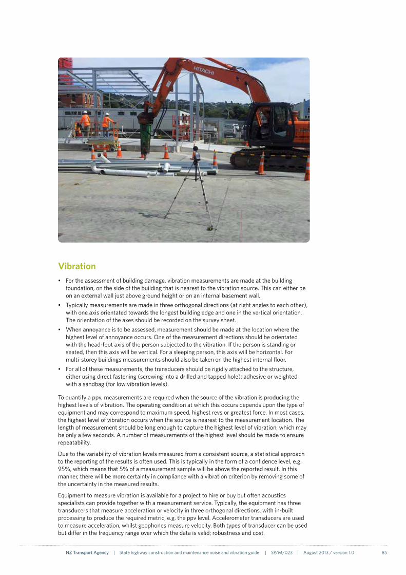
NZ Transport Agency | State highway construction and maintenance noise and vibration guide | SP/M/023 | August 2013 / version 1.0 85
Vibration • Fortheassessmentofbuildingdamage,vibrationmeasurementsaremadeatthebuilding
foundation, on the side of the building that is nearest to the vibration source. This can either be on an external wall just above ground height or on an internal basement wall.
• Typicallymeasurementsaremadeinthreeorthogonaldirections(atrightanglestoeachother),with one axis orientated towards the longest building edge and one in the vertical orientation. The orientation of the axes should be recorded on the survey sheet.
• Whenannoyanceistobeassessed,measurementshouldbemadeatthelocationwherethehighest level of annoyance occurs. One of the measurement directions should be orientated with the head-foot axis of the person subjected to the vibration. If the person is standing or seated, then this axis will be vertical. For a sleeping person, this axis will be horizontal. For multi-storey buildings measurements should also be taken on the highest internal floor.
• Forallofthesemeasurements,thetransducersshouldberigidlyattachedtothestructure,either using direct fastening (screwing into a drilled and tapped hole); adhesive or weighted with a sandbag (for low vibration levels).
To quantify a ppv, measurements are required when the source of the vibration is producing the highest levels of vibration. The operating condition at which this occurs depends upon the type of equipment and may correspond to maximum speed, highest revs or greatest force. In most cases, the highest level of vibration occurs when the source is nearest to the measurement location. The length of measurement should be long enough to capture the highest level of vibration, which may be only a few seconds. A number of measurements of the highest level should be made to ensure repeatability.
Due to the variability of vibration levels measured from a consistent source, a statistical approach to the reporting of the results is often used. This is typically in the form of a confidence level, e.g. 95%, which means that 5% of a measurement sample will be above the reported result. In this manner, there will be more certainty in compliance with a vibration criterion by removing some of the uncertainty in the measured results.
Equipment to measure vibration is available for a project to hire or buy but often acoustics specialists can provide together with a measurement service. Typically, the equipment has three transducers that measure acceleration or velocity in three orthogonal directions, with in-built processing to produce the required metric, e.g. the ppv level. Accelerometer transducers are used to measure acceleration, whilst geophones measure velocity. Both types of transducer can be used but differ in the frequency range over which the data is valid; robustness and cost.

86 NZ Transport Agency | State highway construction and maintenance noise and vibration guide | SP/M/023 | August 2013 / version 1.0
Unmanned logging equipmentSome projects may require noise and/or vibration to be monitored continuously or for long periods of time, due to the nature of the works or to comply with a designation condition. Attended measurements over such periods would be expensive and in most instances not be practicable.
In these cases, unattended noise and vibration loggers are used. Typically these will record noise and vibration levels at a fixed time interval. Short intervals can be used to quantify the noise from short-term events (eg 1 minute) and subsequent processing can be used to combine these short intervals into the required sample length (typically 15 minutes). Short intervals allow spurious data points to be removed from the average. Typically intervals of 1 second are used to quantify the ppv of vibration.
The levels from unattended monitoring should also be used with caution, as it will often be difficult to identify the source of the noise or vibration, giving erroneous results if high levels are recorded by sources not directly associated with the works. Obtaining site activity records will assist in identifying any spikes in measured noise or vibration. Careful location of the equipment will minimise this effect, for example: shielding a logger from the noise generated by an adjacent industrial source.
Meteorological conditions should also be quantified during noise monitoring over long periods of time, particularly when measuring noise at long distances from the source, as wind direction and speed can affect the noise propagation significantly.
Modern equipment allows high levels of noise or vibration to trigger the recording of audio samples, which can be subsequently used to assist with source identification. Remote access is also available to check on operation and download results. Data storage, power requirements and security must also be considered.
Reporting• Onsite,fillinallpartsofthesurveysheets.• LogtheresultsintheprojectdatabaseontheNZTATransportNoisewebsite(section5.10).• Ifrequired,prepareaformalreportfortheprojectteamand/orconsentingauthority40 ,
referencing the designation conditions (CSVue).40 Local Government New Zealand. Council websites and boundary maps. www.lgnz.co.nz

NZ Transport Agency | State highway construction and maintenance noise and vibration guide | SP/M/023 | August 2013 / version 1.0 87
5.10 Documentation
Project databaseAll projects should have a comprehensive construction noise and vibration records system, which, depending on the level of risk, will include: management plans; management schedules; calculations; monitoring results; and complaints records. This should preferably be in electronic form and using the NZTA Transport Noise website facility where nominated project team members can save and view all project construction noise and vibration information. This also allows the NZTA to maintain a national overview of construction noise and vibration management. In some cases an alternative, project-specific database that covers all the aspects of environmental management could be used, as could a regional system such as that operated by the Auckland Motorways Alliance. This, however, prevents a national overview. Whatever system is used, the same information requirements apply.
The following sections detail the key information that should be saved within a specific database for construction noise and vibration issues. The information is required for compliance with NZS 6801:2008, NZS 6803:1999, BS 5228-2:2009, ISO 4866:2010 and current good practice. In some instances resource consent or designation conditions may require additional information to be recorded.
Communication and complaint registerA record should be kept of all contacts, communication and liaison with neighbours regarding construction noise. This should include:
• date of contact• people involved• brief summary of the discussions held.
For complaints (section 5.8) this should include:
• time, date and location• complainant name and contact number • description of noise/vibration/equipment reported • immediate action taken to address complaint, including timeframe • investigation and corrective actions taken, including timeframes • follow-up check, including timeframe• details of complaint closure.
There may be communication and complaint registers as part of project-wide systems for other issues as well as noise. In that instance the CNVMP should contain a reference to the location of the central registers. Construction noise and vibration complaints can be tracked on the NZTA Transport Noise website.

88 NZ Transport Agency | State highway construction and maintenance noise and vibration guide | SP/M/023 | August 2013 / version 1.0
Insert company or project
logo:
- right aligned on the page
- middle aligned with NZTA
Construction noise
management plan
[click and type project name]
[click and type date of issue]
[click and type document reference]
Insert company or project
logo: - right aligned on the page
- middle aligned with NZTA
Construction noise
management schedule
[click and type project name]
[click and type site/activity name]
[click and type date of issue]
[click and type document reference]
Construction Noise and Vibration Management PlanAs outlined in section 5.1, a CNVMP, or alternatively a section included in the SEMP, should detail consultant and contractor obligations during construction and maintenance, and should include:
• applicable noise and vibration criteria
• consent/designation condition requirements
• identification of the most affected houses and other sensitive locations where noise and/or vibration limits apply
• description of the works, anticipated equipment/processes and durations
• assessment of construction noise and vibration levels
• appropriate mitigation measures to be implemented
• monitoring and reporting requirements
• staff training/awareness programme
• procedures for maintaining contact with stakeholders and managing complaints
• contact numbers for key construction staff, staff responsible for assessment and council officers, including at least one NZTA staff member.
If any of these details are not available when first preparing the CNVMP then it should be updated when the information becomes available. Construction noise and vibration induction sheets are part of the CNVMP and should be filed with the plan as they are completed.
Construction noise and vibration management schedulesA CNVMS provides a specific assessment of an activity and/or location and should include details such as:
• activity location, start and finish dates
• the nearest neighbours to the activity
• a location plan
• predictions and mitigation for the activity
• communication with neighbours
• location, times and type of monitoring
• a staff sign-off sheet.
Templates for a management plan and schedule are available on the NZTA Transport Noise website.

NZ Transport Agency | State highway construction and maintenance noise and vibration guide | SP/M/023 | August 2013 / version 1.0 89
Monitoring registerAll details relating to noise and vibration monitoring should be stored in the construction noise and vibration database, including the following:
• Site survey sheets and associated aerial photographs.
• Site survey summary sheet.All site results can be recorded on the NZTA Transport Noise website. The key elements to be observed and entered into the survey sheet, and then recorded, are:
- date - time (measurement start time) - construction location - construction activity - measurement location street address - measurement duration (minutes) - noise metrics, eg LAeq(t), LAFmax. - vibration metrics, eg ppv.
• Survey reports (both internal reports and reports submitted to council).
• Survey and equipment operating procedures.
• Current and past equipment kit details and calibration summary:
Rather than record equipment details during each survey, the requirements of NZS 6801 can be achieved by maintaining an accurate register of equipment kits in the construction noise database. It is therefore important that all previous equipment data is retained. For each measurement kit the equipment summary should include:
- sound level meter type, serial number and last calibration date and certificate reference - microphone type, serial number and last calibration date and certificate reference (this
often forms part of the sound level meter calibration) - field calibrator type, serial number and last calibration date and certificate reference - wind shield type - tripod type - wind meter type - copies of calibration certificates.
A similar equipment summary for vibration equipment could also be used.
Insert company or project
logo:
- right aligned on the page
- middle aligned with NZTA
Construction noise survey
report
[click and type project name]
Measurements on [click and type measurement date]
[click and type date of issue]
[click and type document reference]

90 NZ Transport Agency | State highway construction and maintenance noise and vibration guide | SP/M/023 | August 2013 / version 1.0
Case study – Vibration measurementsThe case study on page 4 describes the good practice carried out on the Victoria Park Tunnel (VPT) project in terms of the noise and vibration management, a proactive approach and communicating effectively with neighbours. This case study describes the vibration monitoring carried out during that project as part of the overall management system. Monitoring was required to verify compliance with a designation condition which referenced vibration criteria in DIN 4150-3.
Between January 2010 and October 2011, 204 vibration measurements were undertaken by the project staff and consultants, and results compiled into a register. The monitoring was mainly proactive measurements (198), with a small number of measurements in response to complaints about vibration (6). Proactive measurements were typically taken at the start of a construction activity that was envisaged to produce significant levels of vibration near to a receiver sensitive to building damage or human annoyance.
A combination of manned and unmanned measurements was used. The vibration was measured in three directions with transducers typically clamped to a vertical structure or held in place on a horizontal surface using a sandbag. The following two photos show appropriate mounting positions, measuring vibration near or on the foundation of a structure to assess building damage. For the assessment of human response, the transducers would be typically mounted on an internal floor (table 2.3).
Some of the measurements for the VPT project did not use appropriate measurement locations. The example shown in figure 5.8 will not measure vibration comparable with the guideline values in DIN 4150 as this arrangement measures the response of the specific wall rather than the foundation of the building.
FIGURe 5.7 Transducer mounting methods used on the VPT project
TransducersClamp
Transducers under sandbag
Vibration meter
FIGURe 5.8 Incorrect transducer location
Transducers under sandbag

NZ Transport Agency | State highway construction and maintenance noise and vibration guide | SP/M/023 | August 2013 / version 1.0 91
In order to assess the potential for building damage according to the DIN 4150-3 guidelines, the frequency of the ppv is also required, as the effect of vibration on structures is frequency dependent. Where recorded in the register, Figure 5.9 presents the vibration level against frequency. The DIN 4150-3 guideline levels are also included for comparison. Monitoring was required to verify compliance with a designation condition which referenced vibration criteria in DIN 4150-3.
FIGURe 5.9 Vibration levels measured on VPT project
LeSSONS LeARNT
From review of the monitoring records, the following improvements to the vibration measurement methodology have been identified which should be implemented for future projects:
• Thelocationofthemeasuringtransducersshouldbedeterminedbytheeffecttobeassessed(see section 2.2):
- Human response/annoyance – at the location where the vibration is felt, eg on an internal floor
- Building damage – at the building foundation.
If access prevents the use of these locations, then measurements can be made elsewhere with the appropriate corrections applied for the foundation and building response (page 59).
• Thefrequencyoftheppvshouldberecordedastheresponseofahumanandabuilding,andthecorresponding criteria, are frequency dependent.
• Ifunmannedmeasurementsaretobeused,thetransducersmustbeinalocationwheretheeffects of erroneous vibration sources is minimised. Such sources may include intentional or unintentional knocking of the transducers by site workers or the public.
• Thesourceofvibrationduringeachmeasurementshouldbedetermined.Thismaybedifficultwhere there is lots of construction activity occurring at the same time. Temporarily stopping and restarting individual activities can assist in the identification of the source.
• Consistentterminologyanddataentriesshouldbemadeinthevibrationregistertoassistwithcomprehension and subsequent analysis.
0
5
10
15
20
25
30
35
40
Frequency, Hz
0 10 20 30 40 50 60 70 80 90 100
Com
pone
nt p
eak
part
icle
vel
ocity
, mm
/s
Drilling
Blasting
Piling-sheet
Concrete breaking
VPT measured dataLine 1 - Commercial/industrial buildingsLine 2 - ResidentialLine 3 - Historic/sensitive structures


Glossary 94
References 98
Glossary and references
Glossary & references

94 NZ Transport Agency | State highway construction and maintenance noise and vibration guide | SP/M/023 | August 2013 / version 1.0
Glossary
A-WeIGHTING Human hearing is less sensitive at very low and very high frequencies. Noise measurements capture all frequencies and therefore need to be adjusted to correspond to human hearing. This adjustment is called ‘A-weighting’.
AIRBLAST OVeRPReSSURe
Airblast overpressure is an acoustic effect caused by blasting where significant airborne energy is generated at frequencies lower than is typically audible by a human ear but which can cause subsequent vibrations at audible frequencies within buildings.
AIRBORNe NOISe Noise inside or outside a building caused by sound propagated through the air.
ALTeReD ROAD An existing road that is subject to alterations of the horizontal or vertical alignment which meets the criteria in section 1.5 of NZS 6806, including certain sound level thresholds.
AS Australian Standard.
BARRIeR A structure that is placed between a noise source and a receiver to reduce the noise. In this guide, ‘barrier’ refers to both wall type structures and berms/bunds.
BeST PRACTICABLe OPTION (BPO)
The best method for preventing or minimising the adverse effects on the environment, having regard, among other things, to:
- the nature of the discharge or emission and the sensitivity of the receiving environment to adverse effects, and
- the financial implications, and the effects on the environment, of that option when compared with other options, and
- the current state of technical knowledge and the likelihood that the option can be successfully applied.
BLASTING The breaking-up of rock or other hard material by the use of explosives.
BROADBAND A broadband source emits noise or vibration at a wide range of frequencies.
CNVMP Construction Noise and Vibration Management Plan. A document detailing the obligations towards noise and vibration of the NZTA and its consultants and contractors.
CNVMS Construction noise and vibration management schedule, also known as a Site Specific Construction Noise Management Plan (SSCNMP) or job noise analysis. A specific noise and vibration assessment of an activity and/or location.
COMPACTION The consolidation of material during construction of a road or structure. This is often carried out using a heavy weight and/or vibration of the material.
COMPONeNT PPV The ppv for one measurement direction. See also resultant ppv.
CONDITION SURVey
The inspection of a structure by a qualified engineer to assess the current state. Where construction work is likely to produce significant vibration, before and after condition surveys are used to gauge cosmetic or structural damage.
CONDITIONS Conditions placed on a resource consent (pursuant to section 108 of the RMA) or on a designation (pursuant to subsection 171(2)(c) or subsection 149P(4)(b) of the RMA).
CONTINUOUS VIBRATION
Vibration that is maintained for an indefinite period of time.

NZ Transport Agency | State highway construction and maintenance noise and vibration guide | SP/M/023 | August 2013 / version 1.0 95
COSMeTIC DAMAGe
The formation or growth of hairline cracks on plaster or drywall surfaces and in the mortar joints of a brick/concrete block construction.
DeCIBeL (dB) A unit of measurement on a logarithmic scale which describes the magnitude of sound pressure with respect to a reference value (20 µPa).
DIReCTIONAL Some sound sources can produce different sound levels at the same distance from the source, depending on direction. These sources are known as ‘directional sources’.
DISTANCe CORReCTION
As sound propagates away from a source, the sound level reduces. A distance correction is the amount of reduction in sound level.
eXISTING ROAD A formed legal road existing at the time when road-traffic noise effects of a new or altered road are assessed in accordance with NZS 6806.
FACADe The outside of an external wall of a building. A +3dB difference is often used between the facade noise level (building present) and the free-field noise level (no building). This difference is known as the ‘facade correction’.
FRee-FIeLD Description of a location which is at least 3.5m from any significant sound-reflecting surface other than the ground.
GROUND BORNe NOISe
Noise inside a building caused by vibration of the building structure due to vibration through the ground from an external vibration source.
GROUND BORNe VIBRATION
Vibration inside or outside a building due to vibration through the ground from an external vibration source.
HeRTZ Unit of frequency, used for both sound and vibration.
LAeq(15min) The A-weighted time-average sound level over a 15-minute period, measured in units of decibels (dB).
LAFmax The maximum A-weighted noise level with a 1/8 second or ‘Fast’ time constant (indicated by a ‘F’), measured in units of decibels (dB).
LOGARITHMIC Logarithmic scales reduce wide-ranging quantities to smaller scales. For example, the decibel is a logarithmic unit quantifying sound pressure.
LZpeak The peak un-weighted (indicated by a ‘Z’) noise level with no time constant, measured in units of decibels (dB).
MOVING SOURCe A noise source that does not stay in one place. In terms of construction noise and vibration, an example of a moving source would be a truck delivering material.
NeW ROAD Any road which is to be constructed where no previously formed legal road existed. This includes the formation of a previously unformed legal road.
NOISe Noise may be considered as sound that serves little or no purpose for the exposed persons and is commonly described as 'unwanted sound'.
NOISe AND VIBRATION RISK
The risk of works causing annoyance and/or building damage, and also the related risks of costly mitigation or affecting statutory approvals.
NZTA NZ Transport Agency. The crown entity responsible for, amongst other functions, the management and maintenance of the state highway network.
PeRCePTILe Noticeable by humans.

96 NZ Transport Agency | State highway construction and maintenance noise and vibration guide | SP/M/023 | August 2013 / version 1.0
PILING A column of wood or steel or concrete that is driven into the ground to provide support for a structure. Piles can be driven by impact, vibration or rotating.
PPV Peak particle velocity. This is the instantaneous maximum velocity reached by the vibrating surface as it oscillates about its normal position.
ReSULTANT PPV The combination of the velocity of three orthogonal directions using a ‘root-mean-squared’ summation.
PROTeCTeD PReMISeS AND FACILITIeS (PPFS)
Spaces in buildings used for:
• residentialactivities• marae• overnightmedicalcare• teaching(andsleeping)ineducationalfacilities• playgroundsthatarepartofeducationalfacilitiesthatarewithin20mofbuildingsused
for teaching purposes.
PSeUDO ReSULTANT
A ‘square-root of the sum of squares’ (SRSS) of 2 or more vibration levels on orthogonal axes. Otherwise known as the ‘simulated resultant’. It is the vector addition of the maximum level of each direction regardless of the time it occurs. Thus this level of vibration will never occur and assessments based on these data will be over-estimates and therefore conservative.
RMA Resource Management Act 1991.
SIMULATeD ReSULTANT
See pseudo resultant
SOUND Sound (pressure) levels are an objective measure of changes in pressure levels that may be heard by humans. Unwanted sound can be considered as noise.
SPeCTRA/SPeCTRAL DATA
A graph/table of sound or vibration level versus frequency.
SOUND PReSSURe The local pressure deviation from the ambient (average or equilibrium) atmospheric pressure caused by a sound wave.
SOUND POWeR A measure of the energy of a sound source per time unit. Sound power is neither room dependent nor distance dependent. Sound power is only attributed to the sound source.
TIMe CONSTANT During a noise measurement, a sound level meter averages the rapidly varying signal from the microphone into a slow-moving signal that allows the sound level to be ‘read’ by the operator. The time over which this average is calculated is the ‘time constant’ and originally corresponded to the speed at which the damped needle moved on an analogue sound level meter. The calculations made on modern digital meters replicate this effect with the same time constants. Typical time constants are ‘Slow’ of 1 second duration (often denoted ‘S’) or ‘Fast’ of 1/8 second duration (‘F’).
TRANSIeNT VIBRATION
Transient vibration is temporarily sustained vibration but which may be frequently repeated. For example, the vibration resulting from impact piling.
VIBRATION Vibration is a periodic motion about a normal position. In this guide, vibration refers to the movement in the ground (‘ground borne vibration’) or in a structure.

NZ Transport Agency | State highway construction and maintenance noise and vibration guide | SP/M/023 | August 2013 / version 1.0 97

98 NZ Transport Agency | State highway construction and maintenance noise and vibration guide | SP/M/023 | August 2013 / version 1.0
References
1. New Zealand Legislation (1991) Resource Management Act. www.legislation.govt.nz
2. Ministry of the Environment (2003) Land Transport Management Act. www.mfe.govt.nz
3. New Zealand Government (2011) Government policy statement on land transport funding 2012/13–2021/22. www.transport.govt.nz
4. NZ Transport Agency (2011) Statement of intent 2012-2015. www.nzta.govt.nz
5. Transit New Zealand (2008) Environment Plan, Version 2. www.nzta.govt.nz
6. Standards New Zealand (1999) NZS 6803:1999 Acoustics – Construction noise. www.standards.co.nz
7. British Standard (2009) BS 5228-2:2009 Code of practice for noise and vibration control on construction and open sites - Part 2: Vibration. www.bsigroup.com
8. British Standard (2009) BS 5228-1:2009 Code of practice for noise and vibration control on construction and open sites - Part 2: Noise. www.bsigroup.com
9. Standards Australia (2010) AS 2436:2010 Guide to noise and vibration control on construction, demolition and maintenance sites. www.standards.org.au
10. Queensland Department of Transport and Main Roads (2008) Road traffic noise management, code of practice, interim edition. www.tmr.qld.gov.au
11. Vicroads (2007) Technical guidelines: Noise guidelines – Construction and maintenance works. www.vicroads.vic.gov.au
12. Department of Environment and Climate Change NSW (2009) Interim construction noise guideline. www.environment.nsw.gov.au
13. Australian (NSW) Department of Environment and Conservation, New South Wales (2006) Assessing vibration: A technical guideline. www.environment.nsw.gov.au
14. Federal Transit Administration (2006) Transit noise and vibration impact assessment, FTA-VA-90-1003-96. www.fta.dot.gov
15. United States Federal Transit Authority (2006) Construction noise handbook, FHWA-HEP-06-015. www.fhwa.dot.gov
16. Dowding (2000) Construction vibrations, 2nd edition, ISBN 0-9644313-1-9.
17. Wikipedia, Acoustics. www.wikipedia.org
18. German Standard DIN 4150-3:1999 Structural vibration – Effects of vibration on structures. www.din.de
19. BSi (2008) BS 6472-1 Guide to evaluation of human exposure to vibration in buildings – Vibration sources other than blasting. www.bsigroup.com
20. Standards New Zealand (2010) NZS 6806:2010 Acoustics – Road traffic noise – New and altered roads. www.standards.co.nz
21. Standards New Zealand (1984) NZS 6803P:1984 The measurement and assessment of noise from construction, maintenance and demolition work, provisional. www.standards.co.nz

NZ Transport Agency | State highway construction and maintenance noise and vibration guide | SP/M/023 | August 2013 / version 1.0 99
22. Australian Standard AS 2187-2:2006 Explosives - Storage and use: Use of explosives. www.standards.org.au
23. NZTA (2012) Technical memorandum - Noise and vibration No. 1 - Construction vibration criteria.
24. Ministry for the Environment (1991) Effective and enforceable consent conditions – A guide to drafting conditions under the Resource Management Act. www.mfe.govt.nz
25. NZTA (2010) Minimum standard Z/4 - Contractor's Social and Environmental Management Plan. www.nzta.govt.nz
26. NZTA (2010) Minimum standard Z/19 – Social and environmental management. www.nzta.govt.nz
27. NZTA (2010) Social and environmental management form, PSF 13, version 2. www.nzta.govt.nz
28. NZTA (2010) Standard Professional Services Guideline PSG/13 – Social and environmental management. www.nzta.govt.nz
29. International Organization for Standardization (1996) ISO 9613-2 Acoustics – Attenuation of sound during propagation outdoors – Part 2: General method of calculation. www.iso.org
30. Northern Gateway Alliance (2008) Newmarket Viaduct Project Construction Noise and Vibration Management Plan. www.nzta.govt.nz
31. New Zealand Transport Agency (2012) Ground vibration from road construction, research report 485. www.nzta.govt.nz
32. US DOT/Transportation Systems Center (1982) Handbook of Urban Rail Noise and Vibration Control, Report UMTA-MA-06-0099-82-2. www.hmmh.com
33. NZTA (2010) Contract procedures manual (SM021), issue 1. www.nzta.govt.nz
34. NZTA (2008) Public engagement policy and guidelines document, working draft. www.nzta.govt.nz
35. Auckland City Council (2007) Code of practice for managing road maintenance noise.
36. NZTA (2005) Guideline for handling environmental complaints. Environmental policy manual (SP/M/023).
37. Standards New Zealand (2008) NZS 6801:2008 Acoustics – Measurement of environmental sound. www.standards.co.nz
38. Standards New Zealand (2008) NZS 6802:2008 Acoustics – Environmental noise. www.standards.co.nz
39. International Standards Organisation (2010) ISO 4866 Mechanical vibration and shock. Vibration of fixed structures. Guidelines for the measurement of vibrations and evaluation of their effects on structures. www.iso.org
40. Local Government New Zealand. Council websites and boundary maps. www.lgnz.co.nz

August 2013
Further informationNZTA Transport Noise website, www.acoustics.nzta.govt.nz
Rob Hannaby Environment and Urban Design Manager Highways and Network Operations – Professional Services Telephone: 09 928 8761 Mobile: 021 242 0853 [email protected]
Our contact details