START SERIAL #MHC-748000572690 OPERATING … Heater Big Buddy... · Mr. Heater | Big Buddy e-2...
16
OPERATING INSTRUCTIONS AND OWNER’S MANUAL READ INSTRUCTIONS CAREFULLY: Read and follow all instructions. Place instructions in a safe place for future reference. Do not allow anyone who has not read these instructions to assemble, light, adjust or operate the heater. PORTABLE PROPANE HEATER FOR RECREATIONAL AND COMMERCIAL USE MH18B Model # 01/10 78438US Rev. D MR. HEATER, INC., 4560 W. 160TH ST., CLEVELAND, OHIO 4413 5 • 216-916-3000 If the information in this manual is not followed exactly, a fire or explosion may result causing property damage, personal injury or loss of life. WARNING: — Do not store or use gasoline or other flammable vapors and liquids in the vicinity of this or any other appliance. — An LP cylinder not connected for use shall not be stored in the vicinity of this or any other appli- ance. — WHAT TO DO IF YOU SMELL GAS • Do not try to light appliance. • • Shut off gas to appliance. — Service must be performed by a qualified service agency. Adequate combustion and ventilation air must be provided. Refer to page 2. START SERIAL #MHC-748000572690 LANGUAGES ENGLISH Pages E1 — E8 SPANISH Pages S1 — S8
Transcript of START SERIAL #MHC-748000572690 OPERATING … Heater Big Buddy... · Mr. Heater | Big Buddy e-2...

OPERATING INSTRUCTIONS AND OWNER’S MANUAL
READ INSTRUCTIONS CAREFULLY: Read and follow all instructions. Place instructions in a safe place for future reference. Do not allow anyone who has not read these instructions to assemble, light, adjust or operate the heater.
PORTABLE PROPANE HEATER FOR RECREATIONAL AND COMMERCIAL USE
MH18B
Model #
01/10 78438US Rev. DMR. HEATER, INC., 4560 W. 160TH ST., CLEVELAND, OHIO 44135 • 216-916-3000
If the information in this manual is not followed exactly, a fire or explosion may result causing property damage, personal injury or loss of life.
WARNING:
— Do not store or use gasoline or other flammable vapors and liquids in the vicinity of this or any other appliance.
— An LP cylinder not connected for use shall not be stored in the vicinity of this or any other appli-ance.
— WHAT TO DO IF YOU SMELL GAS • Do not try to light appliance. • • Shut off gas to appliance.— Service must be performed by a qualified service agency.
Adequate combustion and ventilation air must be provided. Refer to page 2.
START SERIAL #MHC-748000572690
LANGUAGESENGLISH Pages E1 — E8
SPANISH Pages S1 — S8

e-2Mr. Heater | Big Buddy Operating Instructions and Owner’s Manual
warning: Every time hose or tank is connected to unit, connection must be checked for leaks in one or more ways: Apply soapy water to connection, look for bubbles, listen for hiss of escaping gas, feel for extreme cold, smell for rot-ten egg odor. Do not use if leaking!
warning: Any changes to this heater or its controls can be danger-ous.
warning: Early signs of carbon monoxide poisoning resemble the flu, with headache, dizziness and/or nausea. If you have these signs, heater may not be working properly. Get fresh air at once! Have heater serviced.
speciFicatiOnsMODEL NO. .....................................................MH18B
GAS TYPE ......................................................PROPANE
INPUT BTU/HR. ......................... 4,000 / 9,000 /18,000
CLEARANCE TO COMBUSTIBLES
TOP ....................................................................... 30”
FRONT ....................................................................24”
SIDES ...................................................................... 6”
REAR ....................................................................... 0”
warning: If the recreational or commercial enclosure does not have a window or roof vent, DO NOT USE THIS HEATER INSIDE.
tHe state OF caliFOrnia reQuires tHe FOllOwing warning:
warning:Combustion by-products produced when using this product contain carbon monoxide, a chemical known to the State of California to cause cancer and birth defects (or other reproductive harm).
cOntentsGeneral Safety Instructions ............................................ E-2
General Information ....................................................... E-3
Operating with Disposable Propane Cylinders ................ E-3
Operating With Hose Connected to Remote Cylinder ..... E-4
Maintenance.................................................................. E-5
Troubleshooting ............................................................. E-6
Parts List ........................................................................ E-6
Parts Ordering Information ............................................ E-8
Service Information ........................................................ E-8
• Due to high temperatures, the appliance should be located out of traffic and away from combustible materi-als.
• Children and adults should be alerted to the hazard of high surface temperatures and should stay away to avoid burns or clothing ignition.
• Young children should be carefully supervised when they are near the appliance.
• Do not place clothing or other flammable material on or near the appliance.
• Do not operate heater in any moving vehicle.
• This heater can only be used in a recreational or com-mercial enclosure with a window or roof vent. It may also be used outdoors.
• This heater requires a vent area of 18 square inches (example 4 1/4” x 4 1/4” opening) minimum for adequate ventilation during operation. Do not use other fuel burn-ing appliances inside.
• GAS PRESSURE AT HEATER IS REGULATED AND FIXED AT 11” W.C. WHEN USING A REMOTE HOSE CONNEC-TION TO HEATER REGULATOR(S), DO NOT REGULATE OR REDUCE PROPANE TANK SUPPLY PRESSURE TO HEATER.
• warning: ANY HOSE CONNECTION TO A QUICK DIS-CONNECT FITTING ON HEATER MUST BE REGULATED TO 11” W.C. PRESSURE
• REGULATOR(S) IN HEATER MUST ALWAYS BE IN PLACE DURING OPERATION.
• Any safety screen or guard removed for servicing the ap-pliance must be replaced prior to operating the heater.
general saFetY instructiOns tHis is a Heating appliance. dO nOt Operate tHis appliance witHOut tHe FrOnt wire guard installed
cautiOn: Some carpets or linoleum may discolor if heater is placed directly on these floor coverings.
Operating Instructions and Owner’s ManualMr. Heater | Big Buddy e-3
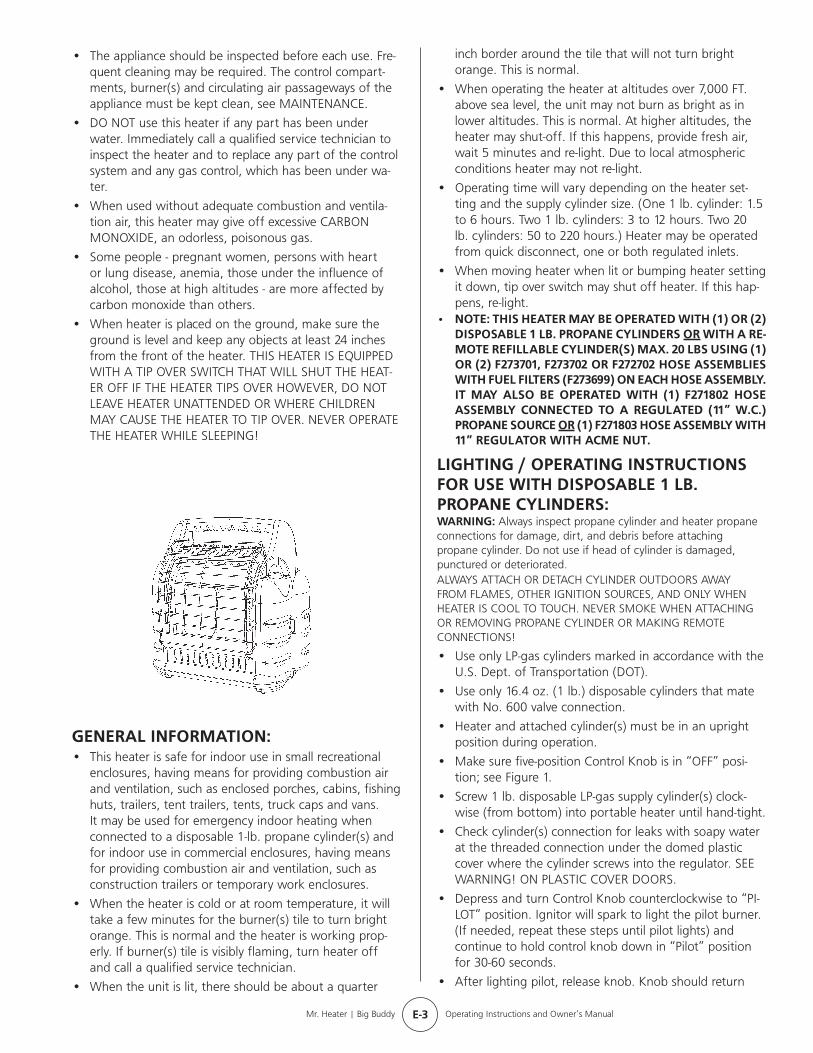
general inFOrMatiOn:• This heater is safe for indoor use in small recreational
enclosures, having means for providing combustion air and ventilation, such as enclosed porches, cabins, fishing huts, trailers, tent trailers, tents, truck caps and vans. It may be used for emergency indoor heating when connected to a disposable 1-lb. propane cylinder(s) and for indoor use in commercial enclosures, having means for providing combustion air and ventilation, such as construction trailers or temporary work enclosures.
• When the heater is cold or at room temperature, it will take a few minutes for the burner(s) tile to turn bright orange. This is normal and the heater is working prop-erly. If burner(s) tile is visibly flaming, turn heater off and call a qualified service technician.
• When the unit is lit, there should be about a quarter
• The appliance should be inspected before each use. Fre-quent cleaning may be required. The control compart-ments, burner(s) and circulating air passageways of the appliance must be kept clean, see MAINTENANCE.
• DO NOT use this heater if any part has been under water. Immediately call a qualified service technician to inspect the heater and to replace any part of the control system and any gas control, which has been under wa-ter.
• When used without adequate combustion and ventila-tion air, this heater may give off excessive CARBON MONOXIDE, an odorless, poisonous gas.
• Some people - pregnant women, persons with heart or lung disease, anemia, those under the influence of alcohol, those at high altitudes - are more affected by carbon monoxide than others.
• When heater is placed on the ground, make sure the ground is level and keep any objects at least 24 inches from the front of the heater. THIS HEATER IS EQUIPPED WITH A TIP OVER SWITCH THAT WILL SHUT THE HEAT-ER OFF IF THE HEATER TIPS OVER HOWEVER, DO NOT LEAVE HEATER UNATTENDED OR WHERE CHILDREN MAY CAUSE THE HEATER TO TIP OVER. NEVER OPERATE THE HEATER WHILE SLEEPING!
inch border around the tile that will not turn bright orange. This is normal.
• When operating the heater at altitudes over 7,000 FT. above sea level, the unit may not burn as bright as in lower altitudes. This is normal. At higher altitudes, the heater may shut-off. If this happens, provide fresh air, wait 5 minutes and re-light. Due to local atmospheric conditions heater may not re-light.
• Operating time will vary depending on the heater set-ting and the supply cylinder size. (One 1 lb. cylinder: 1.5 to 6 hours. Two 1 lb. cylinders: 3 to 12 hours. Two 20 lb. cylinders: 50 to 220 hours.) Heater may be operated from quick disconnect, one or both regulated inlets.
• When moving heater when lit or bumping heater setting it down, tip over switch may shut off heater. If this hap-pens, re-light.
• nOte: tHis Heater MaY Be Operated witH (1) Or (2) dispOsaBle 1 lB. prOpane cYlinders Or witH a re-MOte reFillaBle cYlinder(s) MaX. 20 lBs using (1) Or (2) F273701, F273702 Or F272702 HOse asseMBlies witH Fuel Filters (F273699) On eacH HOse asseMBlY. it MaY alsO Be Operated witH (1) F271802 HOse asseMBlY cOnnected tO a regulated (11” w.c.) prOpane sOurce Or (1) F271803 HOse asseMBlY witH 11” regulatOr witH acMe nut.
ligHting / Operating instructiOns FOr use witH dispOsaBle 1 lB. prOpane cYlinders:warning: Always inspect propane cylinder and heater propane connections for damage, dirt, and debris before attaching propane cylinder. Do not use if head of cylinder is damaged, punctured or deteriorated. ALWAYS ATTACH OR DETACH CYLINDER OUTDOORS AWAY FROM FLAMES, OTHER IGNITION SOURCES, AND ONLY WHEN HEATER IS COOL TO TOUCH. NEVER SMOKE WHEN ATTACHING OR REMOVING PROPANE CYLINDER OR MAKING REMOTE CONNECTIONS!
• Use only LP-gas cylinders marked in accordance with the U.S. Dept. of Transportation (DOT).
• Use only 16.4 oz. (1 lb.) disposable cylinders that mate with No. 600 valve connection.
• Heater and attached cylinder(s) must be in an upright position during operation.
• Make sure five-position Control Knob is in “OFF” posi-tion; see Figure 1.
• Screw 1 lb. disposable LP-gas supply cylinder(s) clock-wise (from bottom) into portable heater until hand-tight.
• Check cylinder(s) connection for leaks with soapy water at the threaded connection under the domed plastic cover where the cylinder screws into the regulator. SEE WARNING! ON PLASTIC COVER DOORS.
• Depress and turn Control Knob counterclockwise to “PI-LOT” position. Ignitor will spark to light the pilot burner. (If needed, repeat these steps until pilot lights) and continue to hold control knob down in “Pilot” position for 30-60 seconds.
• After lighting pilot, release knob. Knob should return

e-4Mr. Heater | Big Buddy Operating Instructions and Owner’s Manual
ligHting / Operating instructiOns FOr use witH HOse(s) cOnnected tO a reMOte cYlinder, MaXiMuM siZe 20 lBs:• warning: ANY HOSE CONNECTION TO A QUICK DIS-
CONNECT FITTING ON HEATER MUST BE REGULATED TO 11” W.C. PRESSURE
• This Heater may be used in a Recreational Enclosure or Temporary Construction Work Enclosure with a Remote Refillable Propane Cylinder ONLY when the Cylinder is Located Outdoors and the Heater is Used with Mr. Heater Hose No. F273701, F273702 or F272702 and fuel filter F273699. Fuel filter must be replaced annually.
• Mr. Heater Hose No. F271802 which includes a quick disconnect fitting and a 3/8” female flare fitting con-nected to a regulated (11” W.C.) propane source.
• Mr. Heater Hose No. F271803 which includes a quick disconnect fitting and a 11” W.C. regulator.
• danger: NEVER bring a refillable propane cylinder indoors. A fire or explosion can occur causing property damage, serious injury or death!
• Inspect the hose before each use of the heater. If there is excessive abrasion or wear, or the hose is cut, replace prior to using the heater with one of the Mr. Heater Hose No’s. shown above.
• The propane cylinder must include a listed overfilling protection device as well as a collar to protect the cylin-der valve.
• Heater must be in an upright position during operation.
• Make sure five-position Control Knob is in “OFF” posi-tion; see Figure 1, at left.
• Screw hose connector into regulator on heater or con-nect to quick disconnect and screw connector on other end of hose into LP-gas supply cylinder valve. Tighten all hose connections.
• Mr. Heater strongly recommends using disposable fuel filter F273699 to trap any oil substances when connect-ed to a remote cylinder that can make heater inoper-able.
• Open valve at LP-gas supply cylinder.
• Check all hose connections for leaks with soapy water at the threaded connection under the domed plastic cover
to fully extended position. To operate heater slightly depress knob and gently turn to lock in desired position.
• Turn control knob to “LO” or “MD” position to light heater. Leave on “LO” or “MD” position until the left burner tile has turned bright orange.
• After left burner tile has turned bright orange, adjust heat output by turning Control Knob to desired position (“LO”, “MD” or “HI”). Note: Both tiles turn orange only on HI setting.
warning:DO NOT OPERATE HEATER UNLESS CONTROL KNOB IS LOCKED IN A POSITION MARKED “HI”, “MD”, “LO” or “PILOT”. NEVER SET CONTROL KNOB BETWEEN LOCKED POSITIONS. POOR COMBUSTION AND HIGHER LEVELS OF CARBON MONOXIDE MAY RESULT.
• For added heat circulation turn red fan switch to on. The fan switch is located just left of control knob side handle support. See Figure 1.
• Installation of 4 D-cell batteries is required for fan operation. Battery box is located on lower back panel of heater. Follow instructions on battery cover for correct battery installation. See figure 2.
• Heater can also be powered by electrical adapter F276127. Required adapter to be 6 volt DC up to 800 mil-
liamp current with positive tip polarity. See figure 2.
• To shut off heater, slightly push down and turn Control Knob clockwise to “OFF” position.
• cautiOn: After turning heater off, wire guard will remain hot. Allow to thoroughly cool before storing.
• Do not operate, store or remove cylinder(s) near flam-mable items or ignition sources.
• LP-GAS CYLINDERS MUST BE DISCONNECTED FROM HEATER WHEN NOT IN USE!
Figure1
Control Knob
Fan Switch
Figure 2
Electrical Adapter Outlet
Electrical adapter and batteries not included.

Operating Instructions and Owner’s ManualMr. Heater | Big Buddy e-5
where the hose connector screws into the regulator and at LP-gas supply cylinder. SEE WARNING! ON PLASTIC DOORS.
• Depress and turn Control Knob counterclockwise to “PI-LOT” position and hold down for 1 - 5 minutes. This may take longer to purge air from the supply hose depend-ing on the length of the hose being used.
• Depress and turn Control Knob counterclockwise to “PI-LOT” position. Ignitor will spark to light the pilot burner. (If needed, repeat these steps until pilot lights) and continue to hold control knob down in “Pilot” position for 30-60 seconds.
• After lighting pilot, release knob. Knob should return to fully extended position. To operate heater slightly depress knob and gently turn to lock in desired position.
• Turn control knob to “LO” or “MD” position to light heater. Leave on “LO” or “MD” position until first burner tile has turned bright orange.
• After first burner tile has turned bright orange, adjust heat output by turning Control Knob to desired position (“LO”, “MD” or “HI” setting).
caution: Do not try to adjust heating levels by using the propane tank shut-off valve,
warning:DO NOT OPERATE HEATER UNLESS CONTROL KNOB IS LOCKED IN A POSITION MARKED “HI”, “MD”, “LO”or “PILOT”. NEVER SET CONTROL KNOB BETWEEN LOCKED POSITIONS. POOR COMBUSTION AND HIGHER LEVELS OF CARBON MONOXIDE MAY RESULT.
• Installation of 4 D-cell batteries is required for fan operation. Battery box is located on lower back panel of heater. Follow instructions on battery cover for correct battery installation. See figure 2.
• Heater can also be powered by electrical adapter, F276127. Required adapter to be 6 volt DC up to 800 mil-liamp current with positive tip polarity. See figure 2.
• To shut off heater, shut off propane at supply tank, al-low heater to use-up propane in supply line until heater shuts off, then slightly push down and turn Control Knob clockwise to “OFF” position.
• cautiOn: After turning heater off, wire guard will remain hot. Allow to thoroughly cool before storing.
• When not in use, the gas must be turned off at the LP-gas supply cylinder. As stated before allow heater to use up propane in supply line until heater shuts off. When the LP-gas supply cylinder is not disconnected from the heater, the heater and the cylinder must be stored outdoors, in a well ventilated space, out of reach of children, and must not be stored in a building, garage or any other enclosed area.
• Indoor storage of the heater is permissible only if the cylinder is disconnected and removed from the heater. Cylinders must be stored outdoors out of the reach of children and must not be stored in a building, garage or any other enclosed area.
Maintenance:Always keep the heater area clear and free from combustible materials, gasoline and other flammable vapors and liquids.Keep the vent areas (slots in the bottom and the top at the front of heater) clear at all times.Visually inspect the pilot flame and burner periodically during use. The pilot flame should be blue in color (not yellow) and will extend beyond the thermocouple. The flame will surround the thermocouple just below the tip, see Figure 3. A slight yellow flame may occur where the pilot flame and main burner flame meet. The burner(s) should be bright orange (with a slight blue color around the border, a red-orange haze that is visible on the ceramic tile is acceptable) and without a noticeable flame. A blue flame that rolls out at the top of the ceramic tile indicates an accumulation of dust, lint or spider webs inside the casing assembly and main burner assembly. If the pilot is yellow or the burner has a noticeable flame, cleaning may be required. Use the following procedure to inspect the casing assembly and main burner assembly.It is necessary to periodically check the burner(s) orifice and burner venturi tube to make sure they are clear of insects/nests or spider webs that may accumulate over time. A clogged tube can lead to a fire.1 Allow heater to thoroughly cool before performing any
maintenance.2 Remove disposable 1 lb. cylinder(s) from heater or turn
OFF gas supply at remote cylinder valve, and disconnect hose from heater.
3 Remove wire guard from front of heater by gently bend-ing to remove from holes in front cover.
4 Remove (4) screws securing back cover to heater. Lift up slightly to release (2) plastic hooks on top of back cover.
5 Remove back cover.6 Remove (3) screws attaching lower baffle to expose
burner air openings.7 Inspect interior of casing assembly for accumulation
of dust, lint or spider webs. If necessary, clean interior of casing assembly with a vacuum cleaner or apply air pressure. Do not damage any components within casing assembly when you are cleaning.
8 Inspect and clean main burner orifice located at bottom of burner venturi tube, by using a vacuum or apply air pressure at orifice opening.
Figure 3

e-6Mr. Heater | Big Buddy Operating Instructions and Owner’s Manual
9 Inspect and clean pilot (mounted to bracket) by using a vacuum or apply air pressure through the holes in the pilot indicated by the arrows in Figure 3. warning: Never use needles, wires, or similar cylin-drical objects to clean the pilot to avoid damaging the calibrated ruby that controls the gas flow.
10 Apply air pressure into ceramic tile of burner(s) assembly and the venturi tube (with [2] air openings) to remove dust, lint or spider webs.
11 Reinstall lower baffle with (3) screws12 Slide back cover over (2) plastic hooks on top of heater.
Make sure rear cover aligns with plastic side covers. Install (4) screws to hold in place.
trOuBlesHOOting inFOrMatiOn:If Spark electrode does not produce spark. CHECK
• Spark electrode broken – replace.• Igniter wire may not be attached to spark electrode
– attach.• Igniter wire damaged – replace.• Piezo igniter on control valve defective – replace
control valve.If Spark electrode produces spark but pilot does not light. CHECK
• No gas to heater – install disposable cylinder or connect hose and turn on valve at remote cylinder.
• “PILOT” position not properly aligned – turn gas control knob to “PILOT” position and depress.
• Pilot is blocked from spider web or dirt – clean pilot, see MAINTENANCE.
If Pilot flame does not stay lit when knob is released. CHECK
• Control knob in “PILOT” position not completely depressed or held in long enough to purge air from lines.
• Pilot flame not surrounding thermocouple – clean pilot, see MAINTENANCE.
• Pilot Assembly defective – replace.• Tip switch wires disconnected – connect.
If Main burner(s) does not ignite. CHECK
• Main burner(s) orifice is blocked – clean burner(s), see MAINTENANCE.
If Heater keeps shutting “OFF” during normal operation. CHECK
• Pilot is blocked – clean pilot, see MAINTENANCE.• Provide minimum fresh air opening of 18 square
inches (example 4 1/4” x 4 1/4” opening).• Tip over switch activated from bumping heater. Re-
light
accessOries:
iteM # descriptiOn
F273701 5 ft. PROPANE HOSE ASSEMBLY (Swivel 1”-20 Male Throwaway Cyl. Thd. X P.O.L. w/Handwheel) F273702 12 ft. PROPANE HOSE ASSEMBLY (Swivel 1”-20 Male Throwaway Cyl. Thd. X P.O.L. w/Handwheel) F272702 12 ft. PROPANE HOSE ASSEMBLY (Swivel 1”-20 Male Throwaway Cyl. Thd. X P.O.L. w/Handwheel) F273699 Fuel Filter (Replace Annually) F271802 12 ft. PROPANE HOSE ASSEMBLY w/quick disconnect fittings and 3/8” female flare fitting F271803 12 ft. PROPANE HOSE ASSEMBLY w/quick disconnect fittings and 11” W.C. regulator w/Acme nut.
parts list:see BacK page FOr parts Ordering inFOrMatiOn
reF. # iteM # descriptiOn1 78402 HANDLE, ASSEMBLY, GRAY 78441 HANDLE, ASSEMBLY, BLACK2 78403 FAN, SWITCH3 78442 BACK, FAN, COVER4 78404 BACK PANEL ASSEMBLY (Includes parts 3, 5, 6, 7, and 8)5 78406 FAN, BLOWER, WHEEL6 78407 FAN, INTAKE, COVER7 78408 DOOR, BATTERY, COVER, GRAY 78443 DOOR, BATTERY, COVER, BLACK8 78409 BATTERY, TERMINALS9 78410 DOOR LEFT SIDE COVER, GRAY 78444 DOOR LEFT SIDE COVER, BLACK10 78411 LEFT, SIDE, COVER, GRAY 78445 LEFT, SIDE, COVER, BLACK11 78412 (2) REGULATORS, MH18B12 78413 TIE, WRAPS13 78414 BRACKET, LEFT, SIDE, REG,14 78415 LEFT, SIDE, GAS, SUPPLY, LINE15 78416 FRAME, ASSEMBLY16 78417 BRACKET, RIGHT, SIDE, REG,17 78418 KNOB, CONTROL, RED 78512 KNOB, CONTROL, GREEN18 78419 DOOR, RIGHT, SIDE, COVER, GRAY 78446 DOOR, RIGHT, SIDE, COVER, BLACK19 78420 RIGHT, SIDE, COVER, GRAY 78447 RIGHT, SIDE, COVER, BLACK20 78421 VALVE, CONTROL, ASSEMBLY21 78422 PILOT, ASSEMBLY22 78423 SHIELD, HEAT, BACK23 78424 SHIELD, HEAT, FRONT24 78425 COVER, FRONT, RED 78448 COVER, FRONT, YELLOW 78513 COVER, FRONT, GREEN25 78426 GUARD, WIRE FACE 78449 GUARD, WIRE FACE, HD26 78427 BRACKET, BOTTOM, PLENUM, ASSEMBLY27 78428 PILOT, BRACKET28 78429 REFLECTOR29 73439 TILE30 73433 TILE, GASKET (NOT SHOWN)31 78431 PLENUM, BODY32 78432 BRACKET, TOP, PLENUM, ASSEMBLY33 78436 RUBBER FEET (4) NOT SHOWN

Operating Instructions and Owner’s ManualMr. Heater | Big Buddy e-7
Mr.Heater•BigBuddy•Model#MH18B

e-8Mr. Heater | Big Buddy Operating Instructions and Owner’s Manual
Mr. Heater, Inc. reserves the right to make changes at any time, without notice or obligation, in colors, specifications, accessories, materials and models.
Operating instructiOns and Owner’s Manual MH18B
Model #
Mr. Heater, INC., 4560 W. 160TH ST., CLEVELAND, OHIO 44135 • 216-916-3000Mr. Heater and Big Buddy are registered trademarks of Mr. Heater, Inc.© 2003, Mr. Heater. All rights reserved
CSA 4.98U.S.
warning:USE ONLY MANUFACTURER’S REPLACEMENT PARTS. USE OF ANY OTHER PARTS COULD CAUSE INJURY OR DEATH. REPLACEMENT PARTS ARE ONLY AVAILABLE DIRECT FROM THE FACTORY AND MUST BE INSTALLED BY A QUALIFIED SERVICE AGENCY. MR. HEATER HOSES F273701 F273702 AND F272702 ARE SPECIFICALLY DESIGNED FOR USE WITH THIS HEATER ALONG WITH F273699 DISPOSABLE FUEL FILTER. (REPLACE ANNUALLY). USE OF OTHER HOSES MAY CAUSE THE HEATER TO BECOME INOPER-ABLE.
parts Ordering inFOrMatiOn:
purcHasing: Accessories may be purchased at any Mr. Heater local dealer or direct from the factory
FOr inFOrMatiOn regarding serVice
Please call Toll-Free 800-251-0001www.mrheater.com
Our office hours are 8:30 AM – 5:00 PM, EST, Monday through Friday.
Please include the model number, date of purchase, and description of problem in all communication.
liMited warrantY
Mr. Heater, Inc. warrants its heaters and accessories to be free from defects in material and workmanship for a period of 1 year from date of purchase. Mr. Heater, Inc. will repair or replace this product free of charge if it has been proven to be defective within the 1-year period, and is returned at customer expense with proof of purchase to Mr. Heater, Inc. within the warranty period.
04/08 78438US Rev. D

CALENTADOR DE PROPANO PORTÁTIL PARA USO RECREATIVO Y COMERCIAL
01/10 78438US Rev. DMR. HEATER, INC., 4560 W. 160TH ST., CLEVELAND, OHIO 44135 • 216-916-3000
— No almacene ni utilice gasolina ni ningún otro vapor o líquido in¯amable cerca del calentador ni de ningún otro artefacto.
— No deberá almacenar cerca del calentador ni de ningún otro artefacto un cilindro de PL no conectado para su uso.
— QUE HACER SI DETECTA OLOR A GAS · No intente encender el artefacto. · Extinga cualquier llama abierta. · Corte el ¯ujo de gas al artefacto. — La reparación debe ser realizada por una agencia de reparación cali¯cada.
Éste es un calentador portátil con fuego a gas sin ventilación que toma el aire (oxígeno) del área donde es utilizado. Se debe proporcionar combustión y ventilación adecuadas. Consulte la página 3.
Si no se sigue la información en este manual exactamente, puede ocurrir un incendio o una explosión causando daños a la propiedad, lesiones personales o la muerte.
LEA CUIDADOSAMENTE LAS INSTRUCCIONES: Lea y siga todas las instrucciones. Coloque las instrucciones en un lugar seguro para referencias futuras. No permita que nadie que no haya leído estas instrucciones ensamble, encienda, ajuste u opere el calentador.
MH18B
Modelo Nº INSTRUCCIONES DE OPERACIÓN Y MANUAL DEL USUARIO
ADVERTENCIA:
COMIENCE SERIE *MHC-748000572690
LANGUAGESENGLISH Pages E1 — E8
SPANISH Pages S1 — S8

S-2 Instrucciones de operación y manual del usuarioMr. Heater | Big Buddy
ADVERTENCIA: Cada vez que se conecte una manguera o tanque a la
unidad, la conexión debe ser revisada de diferentes maneras para detectar posibles fugas: Aplíquele agua jabonosa a la conexión, observe si hay burbujas, si escucha ruidos de escape de gas, si se siente frío extremo o si huele a huevo podrido. ¡No lo utilice si presenta fugas!
ADVERTENCIA: Cualquier cambio a este calentador o a sus controles puede
ser peligroso.
ADVERTENCIA: Los síntomas tempranos de envenenamiento por monóxido
de carbono se asemejan a los síntomas de la gripe, como por ejemplo dolor de cabeza, mareos y/o náuseas. Si usted tiene cualquiera de estos síntomas, es posible que el calentador no esté funcionando correctamente. ¡Ventile con aire puro inmediatamente! Haga reparar el calentador.
ADVERTENCIA: NO UTILICE ESTE CALENTADOR EN INTERIORES si el
sitio cerrado, recreativo o comercial, no tiene ventana o ventilación en el techo. EL ESTADO DE CALIFORNIA EXIGE LA SIGUIENTE ADVERTENCIA: ADVERTENCIA:-La combustión generada cuando se utiliza este producto contiene monóxido de carbono, un químico conocido en el estado de California reconoce como causante de cáncer y malformaciones congénitas (u otros daños reproductivos).
ADVERTENCIA: NO UTILICE ESTE CALENTADOR EN INTERIORES si el
sitio cerrado, recreativo o comercial, no tiene ventanas o ventilación en el techo.
CONTENIDO
Instrucciones generales de seguridad .............................S-2
Información general .......................................................S-2
Cómo manipular cilindros de propano descartables .......S-4
Cómo manipular mangueras conectadas a cilindros remotos. ........................................................S-5
Mantenimiento ..............................................................S-6
Solución de problemas ...................................................S-6
Lista de partes ...............................................................S-6
Información para el pedido de partes ............................S-7
Información para la reparación .......................................S-8
ESPECIFICACIONESMODELO Nº...................................................... MH18B
TIPO DE GAS ................................................ PROPANO
ENTRADA EN BTU/H .................4.000 / 9.000 / 18.000
MARGEN PARA LOS COMBUSTIBLES
ARRIBA ............................................................76,2 cm
AL FRENTE ........................................................61,0 cm
A LOS LADOS .................................................15,24 cm
ATRÁS ...............................................................0,0 cm
INSTRUCCIONES GENERALES DE SEGURIDADESTE ES UN ARTEFACTO QUE EMITE CALOR. NO OPERE ESTE ARTEFACTO SIN HABER INSTALADO LA REJILLA PROTECTORA FRONTAL.• Debido a las altas temperaturas, se debe ubicar el artefacto
lejos de lugares de paso y de materiales combustibles.• Se debe alertar a niños y adultos del riesgo de las altas
temperaturas en la superficie y deben mantenerse alejados para evitar quemaduras en el cuerpo o de la ropa.
• Se debe supervisar cuidadosamente a los niños pequeños cuando están cerca del artefacto.
• No coloque ropa ni ningún otro material inflamable sobre ni cerca del artefacto.
• No opere el calentador en ningún vehículo en movimiento.• Este calentador puede ser utilizado únicamente en sitios
recreativos o comerciales cerrados que tengan ventanas o ventilación en el techo. También puede ser utilizado al aire libre.
• Este calentador requiere un área de ventilación mínima de 116,12 centímetros cuadrados (por ejemplo: una abertura de 10,8 cm x 10,8 cm) una ventilación adecuada durante su funcionamiento. No utilice en interiores otros artefactos que requieran combustión.
• LA PRESIÓN DE GAS DEL CALENTADOR ES REGULADA Y FIJA A 11” EN COLUMNA DE AGUA. CUANDO SE UTILIZA UNA CONEXIÓN DE MANGUERA REMOTA EN LOS REGULADORES DEL CALENTADOR, NO REGULE NI REDUZCA LA PRESIÓN DEL SUMINISTRO DEL TANQUE DE PROPANO AL CALENTADOR.
• ADVERTENCIA: CUALQUIER CONEXIÓN DE MANGUERA REALIZADA A UN DISPOSITIVO DE DESCONEXIÓN RÁPIDA DEL CALENTADOR DEBE SER REGULADA A UNA PRESIÓN DE 11” EN COLUMNA DE AGUA.
• LOS REGULADORES DEL CALENTADOR DEBEN ESTAR SIEMPRE EN SU LUGAR DURANTE EL FUNCIONAMIENTO.
• Cualquier pantalla o dispositivo protector retirado para reparar el artefacto debe ser colocado nuevamente antes de ponerlo en funcionamiento.
Precaución: Algunas alfombras o superficies del linóleo pueden descolorarse si el calentador se coloca directamente en estas cubiertas de piso.
S-3 Instrucciones de operación y manual del usuarioMr. Heater | Big Buddy
• El artefacto deberá ser inspeccionado antes de cada uso. Es posible que una limpieza frecuente sea necesaria. El control de
los compartimientos, el o los quemadores y los pasos de aire en circulación a través de los conductos del artefacto deben mantenerse limpios, ver la sección de MANTENIMIENTO.
• NO utilice este calentador si alguna parte ha estado sumergida en agua. Llame inmediatamente a un técnico de reparación calificado para que inspeccione el calentador y reemplace cualquier parte del sistema de control y cualquier control de gas, que haya estado sumergido en agua.
• Cuando se lo utiliza sin la combustión y ventilación de aire adecuadas, este calentador puede emanar excesivo MONÓXIDO DE CARBONO, un gas venenoso e inodoro.
• Algunas personas – mujeres embarazadas, personas que sufren enfermedades cardíacas o pulmonares, anemia, aquéllas que están bajo la influencia del alcohol, las que están a altas altitudes – se ven más afectadas por el monóxido de carbono que otras.
• Cuando coloque el calentador en el piso, asegúrese de que la superficie esté nivelada y mantenga cualquier objeto a por lo menos 61 centímetros desde la parte frontal del calentador. ESTE CALENTADOR ESTA EQUIPADO CON UN INTERRUPTOR DE SEGURIDAD QUE HARÁ QUE EL CALENTADOR SE APAGUE SI SE DA VUELTA, SIN EMBARGO, NO DEJE EL CALENTADOR SIN SUPERVISIÓN O DONDE NIÑOS PUEDAN HACER QUE EL CALENTADOR SE VUELQUE. ¡NO HAGA FUNCIONAR NUNCA EL CALENTADOR MIENTRAS DUERME!
El calentador puede ser operado desde el dispositivo de desconexión rápida, una o ambas salidas reguladas.
• Cuando mueva el calentador encendido, o cuando lo golpee o cuando lo asiente, el interruptor de seguridad puede apagar el calentador. Si esto sucede, enciéndalo de nuevo.
• NOTA: ESTE CALENTADOR PUEDE SER OPERADO CON (1) O (2) CILINDROS DESCARTABLES DE PROPANO DE 0,45 KG O (1) O (2) ENSAMBLES DE MANGUERA F273701, F273702 O F272702 CON FILTROS DE COMBUSTIBLE (F273699) EN CADA ENSAMBLE DE MANGUERA. TAMBIÉN PUEDE SER OPERADO CON (1) ENSAMBLE DE MANGUERA F271802 CONECTADO A UNA FUENTE REGULADA DE PROPANO (11” EN COLUMNA DE AGUA) O (1) ENSAMBLE DE MANGUERA F271803 CON UN REGULADOR DE 11” CON TUERCA ACME.
INFORMACIÓN GENERAL:• Este calentador es seguro para usar en interiores y sitios
recreativos pequeños cerrados, con medios para suministrar aire y ventilación para la combustión, tales como porches, cabañas, casitas de pesca, remolques, tiendas remolques, tiendas, cabinas de camiones y camionetas. Se lo puede usar para calentar interiores en emergencias cuando se lo conecta a uno o más cilindros descartables de propano de 0,45 kg y para uso en interiores en espacios cerrados comerciales con medios para suministrar aire y ventilación para la combustión, tales como traileres de construcción o sitios cerrados de trabajos temporales.
Nota: El calentador se puede utilizar al aire libre pero puede experimentar cerrados fastidio en ciertas condiciones del viento.
• Cuando el calentador está frío o a temperatura ambiente, el azulejo del o de los quemadores demorará unos pocos minutos en tornarse anaranjado brillante. Esto es normal y el calentador está funcionando correctamente. Si el azulejo del o de los quemadores tiene llamas visibles, apague el calentador y llame a un técnico de reparación calificado.
• Cuando la unidad está encendida, debe haber un borde de aproximadamente 6,35 milímetros alrededor del azulejo que no se tornará anaranjado brillante. Esto es normal.
• Cuando ponga en funcionamiento el calentador a altitudes superiores a los 2.133,6 M sobre el nivel del mar, es posible que la unidad no queme de forma tan brillante como a altitudes más bajas. Esto es normal. A altitudes más altas, es posible que el calentador se apague. Si esto sucede, suministre aire puro, espere cinco 5 minutos y encienda de nuevo. Debido a las condiciones atmosféricas locales, es posible que el calentador no encienda de nuevo.
• El tiempo de funcionamiento variará según la configuración del calentador y del tamaño del cilindro de suministro. (Un cilindro de 0,45 kg: de 1,5 a 6 horas. Dos cilindros de 0,45 kg: de 3 a 12 horas. Dos cilindros de 9 kg: de 50 a 220 horas.)
INSTRUCCIONES DE OPERACIÓN/ENCENDIDO PARA USAR CON CILINDROS DE PROPANO DESCARTABLES DE 0,45 KG:ADVERTENCIA: Siempre inspeccione el cilindro de propano y las conexiones de suministro de propano al calentador para detectar daños, suciedad y residuos antes de conectar el cilindro de propano. No lo utilice si la cabeza del cilindro está dañada, perforada o deteriorada. SIEMPRE CONECTE O DESCONECTE LOS CILINDROS EN EL EXTERIOR, LEJOS DE LAS LLAMAS, OTRAS FUENTES DE IGNICIÓN Y SOLAMENTE CUANDO EL CALENTADOR ESTE FRÍO AL TACTO. NO FUME CUANDO CONECTE O DESCONECTE UN CILINDRO DE PROPANO O CUANDO HAGA CONEXIONES REMOTAS.• Utilice solamente cilindros de gas PL marcados en conformidad
con el Departamento de Transporte de los EE.UU. (DOT, por sus siglas en inglés).
• Utilice solamente cilindros descartables de 0,45 kg compatibles con la conexión de válvula Nº 600.
• El calentador y el o los cilindros conectados deben estar en una posición vertical durante su funcionamiento.
• Asegúrese de que la perilla de control de cinco posiciones esté en la posición “OFF” (apagado); ver Figura 1.
• Enrosque el o los cilindros descartables de suministro de gas PL de 0,45 kg, en sentido horario (desde abajo), en el calentador portátil hasta que quede ajustado.
• Revise las conexiones del o de los cilindros en busca de fugas con agua jabonosa en la conexión roscada debajo de la cubierta plástica en forma de cúpula donde el cilindro se atornilla al regulador. VEA LA ADVERTENCIA EN LAS PUERTAS DE LA CUBIERTA PLÁSTICA.
• Presione y gire la perilla de control en sentido antihorario hasta la posición “PILOT” (piloto). El encendedor creará una chispa para encender el quemador del piloto, (de ser necesario, repita esta operación hasta que el piloto encienda) y mantenga presionada la perilla de control hacia adentro en la posición “Piloto” por 30-60 segundos.
• Después de encender el piloto, suelte la perilla. La perilla debe quedar extendida por completo. Para operar el calentador presione levemente la perilla y gire suavemente para asegurarla en la posición deseada.
• Gire la perilla de control hasta la posición “LO” (baja) o “MD” (mediana) para encender el calentador. Déjela en la posición “LO” (baja) o “MD” (mediana) hasta que el primer azulejo del quemador se haya tornado anaranjado brillante.
• Después de que el primer azulejo del quemador se haya tornado anaranjado brillante, ajuste la salida de calor girando la perilla de control a la posición deseada “LO” (baja) “MD” (mediana) o “HI” (alta). Note: Ambos azulejos giran la naranja sólo en el HOLA ajuste.
S-4 Instrucciones de operación y manual del usuarioMr. Heater | Big Buddy
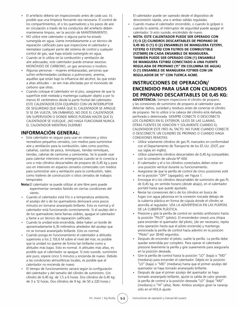
Figura 1
Perilla de control
Interruptor del ventilador
Figura 2
Tomacorriente del adaptador
Adaptador eléctrico
INSTRUCCIONES DE OPERACIÓN/ ENCENDIDO PARA USO CON MANGUERAS CONECTADAS A UN CILINDRO REMOTO, CON DIMENSIÓN MÁXIMA DE 9 KG:• ADVERTENCIA: CUALQUIER CONEXIÓN DE MANGUERA
REALIZADA A UN DISPOSITIVO DE DESCONEXIÓN RÁPIDA DEL CALENTADOR DEBE SER REGULADA A UNA PRESIÓN DE 11” EN COLUMNA DE AGUA.
• Este calentador puede ser utilizado en un espacio recreativo cerrado o en un espacio cerrado para trabajos de construcción
Advertencia: NO OPERE EL CALENTADOR A MENOS QUE LA PERILLA DE
CONTROL ESTE SEGURA EN UNA POSICIÓN MARCADA “LO” (baja) “MD” (mediana) o “HI” (alta) o “PILOT” (piloto). NO COLOQUE NUNCA LA PERILLA DE CONTROL ENTRE LAS POSICIONES MARCADAS. PODRÍA CAUSAR COMBUSTIÓN ESCASA O NIVELES MÁS ALTOS DE MONÓXIDO DE CARBONO.
• Para aumentar la circulación de calor, coloque el interruptor rojo del ventilador en ON (encendido). El interruptor del ventilador está ubicado justo a la izquierda de la perilla de control, al lado del soporte manual. Ver Figura 1.
• Para que el ventilador funcione, se necesitan 4 baterías D. El compartimiento de las baterías está ubicado en el panel posterior inferior del calentador. Siga las instrucciones en la cubierta de las baterías para una correcta instalación de las baterías. Ver figura 2. Note: Ambos azulejos giran la naranja sólo en el HOLA ajuste.
• El calentador también puede recibir suministro eléctrico desde un adaptador eléctrico F276127. Requiere un adaptador de 6 voltios de CC con una corriente de hasta 800 miliamperios con polaridad positiva en la punta. Ver figura 2.
• Para apagar el calentador, presione levemente la perilla de control hacia adentro y gírela en sentido horario hasta la posición “OFF” (apagado).
• PRECAUCIÓN: Después de apagar el calentador, la rejilla protectora permanecerá caliente. Deje enfriar por completo antes de guardar.
• No opere, guarde ni retire el o los cilindros cerca de objetos inflamables o fuentes de ignición.
• ¡LOS CILINDROS DE GAS PL DEBEN SER DESCONECTADOS DEL CALENTADOR CUANDO NO ESTÉN EN USO!
temporales con un cilindro remoto de propano reutilizable SOLAMENTE cuando el cilindro está ubicado en exteriores y el calentador es utilizado con la manguera Mr. Heater Nº F273701, F273702 ó F272702 y filtro de combustible F273699. El filtro de combustible debe ser reemplazado anualmente.
• La manguera Mr. Heater Nº F271802, la cual incluye un dispositivo de desconexión rápida y un accesorio abocinado hembra de 0,95 cm conectado a una fuente regulada de propano (11” en columna de agua).
• La manguera Mr. Heater Nº F271803, la cual incluye un dispositivo de desconexión rápida y un regulador de 11” en columna de agua.
• PELIGRO: No lleve NUNCA un cilindro de propano reutilizable a espacios cerrados. Puede ocurrir un incendio o una explosión causando daños a la propiedad, heridas graves o la muerte.
• Inspeccione la manguera antes de cada uso del calentador. En caso de abrasión o desgaste excesivos, o si la manguera está cortada, reemplácela antes de usar el calentador con una de las mangueras Mr. Heater con la numeración indicada arriba.
• El cilindro de propano debe incluir un dispositivo de protección para sobrellenado listado, así como también un anillo para proteger la válvula del cilindro.
• El calentador debe estar en posición vertical durante el funcionamiento.
• Asegúrese de que la perilla de control de cinco posiciones esté en la posición “OFF” (apagado); ver Figura 1, a la izquierda.
• Enrosque el conector de la manguera en el regulador en el calentador o conecte al dispositivo de desconexión rápida y enrosque el conector en el otro extremo de la manguera en la válvula del cilindro de suministro de gas PL. Ajuste todas las conexiones de las mangueras.
• Mr. Heater enfáticamente recomienda utilizar filtros de combustible descartables F273699 para atrapar cualquier sustancia de aceite cuando se conecte a un cilindro remoto que pueda hacer que el calentador no funcione.
• Abra la válvula en el cilindro de suministro de gas PL.• Revise todas las conexiones de las mangueras en busca de
fugas con agua jabonosa en la conexión roscada debajo de la cubierta plástica en forma de cúpula donde el conector de la manguera se enrosca al regulador y al cilindro de suministro de gas PL. VER LA ADVERTENCIA EN LAS PUERTAS DE LA CUBIERTA PLÁSTICA.
• Presione y gire la perilla de control en sentido antihorario hasta la posición “PILOT” (piloto) y manténgala presionada por 1 - 5 minutos. Esto puede llevar más tiempo para purgar el aire desde la manguera de suministro según la longitud de la manguera que se esté usando.
• Presione y gire la perilla de control en sentido antihorario hasta la posición “PILOT” (piloto). El encendedor creará una chispa para encender el quemador del piloto, (de ser necesario, repita esta operación hasta que el piloto encienda) y mantenga
S-5 Instrucciones de operación y manual del usuarioMr. Heater | Big Buddy
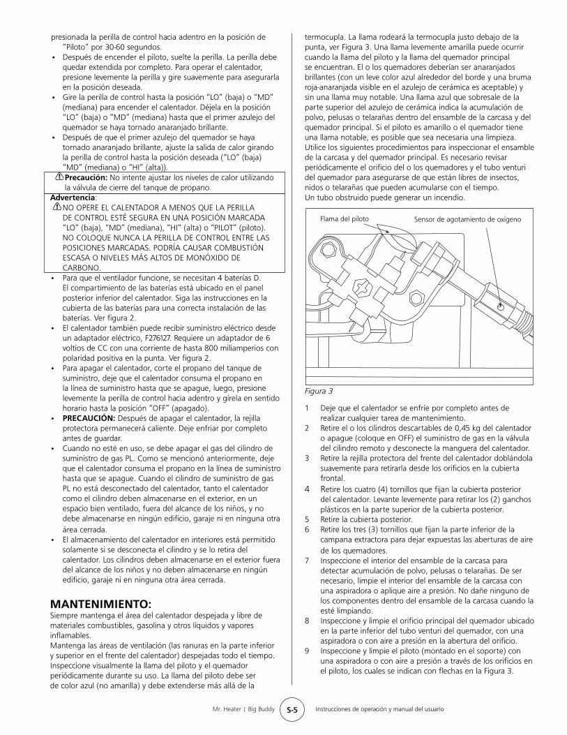
termocupla. La llama rodeará la termocupla justo debajo de la punta, ver Figura 3. Una llama levemente amarilla puede ocurrir cuando la llama del piloto y la llama del quemador principal se encuentran. El o los quemadores deberían ser anaranjados brillantes (con un leve color azul alrededor del borde y una bruma roja-anaranjada visible en el azulejo de cerámica es aceptable) y sin una llama muy notable. Una llama azul que sobresale de la parte superior del azulejo de cerámica indica la acumulación de polvo, pelusas o telarañas dentro del ensamble de la carcasa y del quemador principal. Si el piloto es amarillo o el quemador tiene una llama notable, es posible que sea necesaria una limpieza. Utilice los siguientes procedimientos para inspeccionar el ensamble de la carcasa y del quemador principal. Es necesario revisar periódicamente el orificio del o los quemadores y el tubo venturi del quemador para asegurarse de que están libres de insectos, nidos o telarañas que pueden acumularse con el tiempo.Un tubo obstruido puede generar un incendio.
1 Deje que el calentador se enfríe por completo antes de realizar cualquier tarea de mantenimiento.
2 Retire el o los cilindros descartables de 0,45 kg del calentador o apague (coloque en OFF) el suministro de gas en la válvula del cilindro remoto y desconecte la manguera del calentador.
3 Retire la rejilla protectora del frente del calentador doblándola suavemente para retirarla desde los orificios en la cubierta frontal.
4 Retire los cuatro (4) tornillos que fijan la cubierta posterior del calentador. Levante levemente para retirar los (2) ganchos plásticos en la parte superior de la cubierta posterior.
5 Retire la cubierta posterior.6 Retire los tres (3) tornillos que fijan la parte inferior de la
campana extractora para dejar expuestas las aberturas de aire de los quemadores.
7 Inspeccione el interior del ensamble de la carcasa para detectar acumulación de polvo, pelusas o telarañas. De ser necesario, limpie el interior del ensamble de la carcasa con una aspiradora o aplique aire a presión. No dañe ninguno de los componentes dentro del ensamble de la carcasa cuando la esté limpiando.
8 Inspeccione y limpie el orificio principal del quemador ubicado en la parte inferior del tubo venturi del quemador, con una aspiradora o con aire a presión en la abertura del orificio.
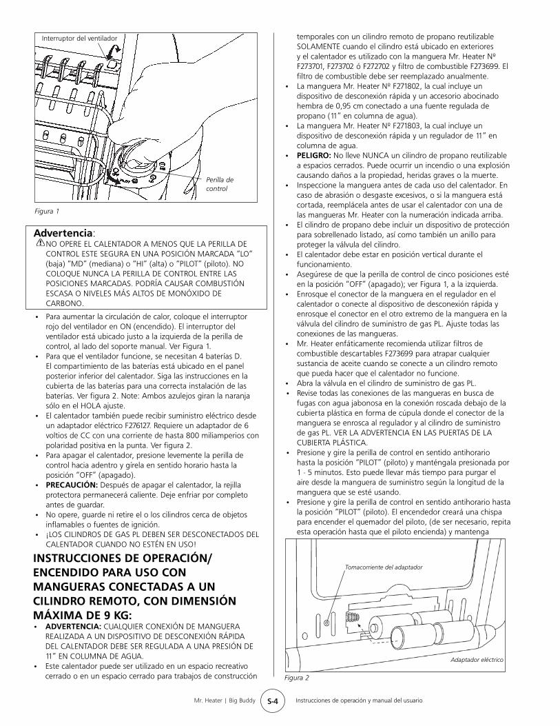
9 Inspeccione y limpie el piloto (montado en el soporte) con una aspiradora o con aire a presión a través de los orificios en el piloto, los cuales se indican con flechas en la Figura 3.
Figura 3
presionada la perilla de control hacia adentro en la posición de “Piloto” por 30-60 segundos.
• Después de encender el piloto, suelte la perilla. La perilla debe quedar extendida por completo. Para operar el calentador, presione levemente la perilla y gire suavemente para asegurarla en la posición deseada.
• Gire la perilla de control hasta la posición “LO” (baja) o “MD” (mediana) para encender el calentador. Déjela en la posición “LO” (baja) o “MD” (mediana) hasta que el primer azulejo del quemador se haya tornado anaranjado brillante.
• Después de que el primer azulejo del quemador se haya tornado anaranjado brillante, ajuste la salida de calor girando la perilla de control hasta la posición deseada (“LO” (baja) “MD” (mediana) o “HI” (alta)).
Precaución: No intente ajustar los niveles de calor utilizando la válvula de cierre del tanque de propano.
Advertencia: NO OPERE EL CALENTADOR A MENOS QUE LA PERILLA
DE CONTROL ESTÉ SEGURA EN UNA POSICIÓN MARCADA “LO” (baja), “MD” (mediana), “HI” (alta) o “PILOT” (piloto). NO COLOQUE NUNCA LA PERILLA DE CONTROL ENTRE LAS POSICIONES MARCADAS. PODRÍA CAUSAR COMBUSTIÓN ESCASA O NIVELES MÁS ALTOS DE MONÓXIDO DE CARBONO.
• Para que el ventilador funcione, se necesitan 4 baterías D. El compartimiento de las baterías está ubicado en el panel posterior inferior del calentador. Siga las instrucciones en la cubierta de las baterías para una correcta instalación de las baterías. Ver figura 2.
• El calentador también puede recibir suministro eléctrico desde un adaptador eléctrico, F276127. Requiere un adaptador de 6 voltios de CC con una corriente de hasta 800 miliamperios con polaridad positiva en la punta. Ver figura 2.
• Para apagar el calentador, corte el propano del tanque de suministro, deje que el calentador consuma el propano en la línea de suministro hasta que se apague, luego, presione levemente la perilla de control hacia adentro y gírela en sentido horario hasta la posición “OFF” (apagado).
• PRECAUCIÓN: Después de apagar el calentador, la rejilla protectora permanecerá caliente. Deje enfriar por completo antes de guardar.
• Cuando no esté en uso, se debe apagar el gas del cilindro de suministro de gas PL. Como se mencionó anteriormente, deje que el calentador consuma el propano en la línea de suministro hasta que se apague. Cuando el cilindro de suministro de gas PL no está desconectado del calentador, tanto el calentador como el cilindro deben almacenarse en el exterior, en un espacio bien ventilado, fuera del alcance de los niños, y no debe almacenarse en ningún edificio, garaje ni en ninguna otra área cerrada.
• El almacenamiento del calentador en interiores está permitido solamente si se desconecta el cilindro y se lo retira del calentador. Los cilindros deben almacenarse en el exterior fuera del alcance de los niños y no deben almacenarse en ningún edificio, garaje ni en ninguna otra área cerrada.
MANTENIMIENTO:Siempre mantenga el área del calentador despejada y libre de materiales combustibles, gasolina y otros líquidos y vapores inflamables.Mantenga las áreas de ventilación (las ranuras en la parte inferior y superior en el frente del calentador) despejadas todo el tiempo. Inspeccione visualmente la llama del piloto y el quemador periódicamente durante su uso. La llama del piloto debe ser de color azul (no amarilla) y debe extenderse más allá de la
Flama del piloto Sensor de agotamiento de oxígeno
S-6 Instrucciones de operación y manual del usuarioMr. Heater | Big Buddy
ADVERTENCIA: No utilice nunca agujas, cables ni objetos cilíndricos similares para limpiar el piloto para evitar dañar el rubí calibrado que controla el paso del gas.
10 Aplique aire a presión en el azulejo de cerámica del ensamble del o de los quemadores y del tubo venturi (con [2] aberturas de aire) para retirar el polvo, las pelusas o telarañas.
11 Reinstale la parte inferior de la campana extractora con los (3) tornillos.
12 Deslice la cubierta posterior sobre los (2) ganchos plásticos en la parte superior del calentador. Asegúrese de alinear la cubierta trasera con las cubiertas plásticas laterales. Instale los (4) tornillos para mantenerla en su lugar.
INFORMACIÓN SOBRE LA SOLUCIÓN DE PROBLEMAS:Si el electrodo de chispas no produce una chispa. VERIFIQUE SI• El electrodo de chispas está roto - reemplácelo.• Es posible que el cable del encendedor no esté conectado al
electrodo de chispas - conéctelo.• El cable del encendedor está dañado - reemplácelo.• El encendedor piezo en la válvula de control tiene fallas -
reemplace la válvula de control.
Si el electrodo de chispas produce una chispa pero el piloto no enciende. VERIFIQUE SI• No hay flujo de gas al calentador - instale un cilindro
descartable o conecte la manguera y encienda la válvula en el cilindro remoto.
• La posición “PILOT” (piloto) no está correctamente alineada - gire la perilla de control del gas hasta la posición “PILOT” (piloto) y presione.
• El piloto está bloqueado por telarañas o suciedad - limpie el piloto, ver la sección de MANTENIMIENTO.
Si la llama del piloto no permanece prendida cuando suelta la perilla. VERIFIQUE SI• La perilla de control, en posición “PILOT” (piloto), no está
totalmente presionada o no ha sido presionada el tiempo suficiente como para purgar el aire de las líneas.
• La llama del piloto no rodea la termocupla - limpie el piloto, ver la sección de MANTENIMIENTO. El ensamble del piloto tiene fallas – reemplácelo.
• Los cables del interruptor de seguridad están desconectados - conéctelos.
Si el o los quemadores principales no encienden. VERIFIQUE SI• El orificio del o los quemadores principales está
bloqueado – limpie el o los quemadores, ver la sección de MANTENIMIENTO.
Si el calentador sigue “APAGÁNDOSE” durante su funcionamiento normal. VERIFIQUE SI• El piloto está bloqueado - limpie el piloto, ver la sección
de MANTENIMIENTO.• Suministre una abertura de aire puro mínima de 116,12
centímetros cuadrados (por ejemplo: una abertura de 10,8 cm x 10,8 cm).
• El interruptor de seguridad se activó al golpear el calentador. Enciéndalo de nuevo.
ACCESORIOS:Nº DE ARTÍCULO DESCRIPCIÓN
F273701 ENSAMBLE DE LA MANGUERA DE PROPANO de 1,52 metros (Placa giratoria de 1”- Rosca macho del cilindro descartable de 9 kg X conexión POL con rueda manual)
F273702 ENSAMBLE DE LA MANGUERA DE PROPANO DE 3,66 metros (Placa giratoria de 1”- Rosca macho del cilindro descartable de 9 kg X conexión POL con rueda manual)
F272702 ENSAMBLE DE LA MANGUERA DE PROPANO DE 3,6 metros (Placa giratoria de 1”-Rosca macho del cilindro descartable de 9 kg X conexión POL con rueda manual)
F273699 Filtro del combustible (Reemplácelo anualmente)
F271802 ENSAMBLE DE LA MANGUERA DE PROPANO de 3,66 metros con dispositivos de desconexión rápida y un accesorio abocinado hembra de 0,9 cm.
F271803 ENSAMBLE DE LA MANGUERA DE PROPANO de 3,66 metros con dispositivos de desconexión rápida y un regulador de 11”en columna de agua con tuerca Acme.
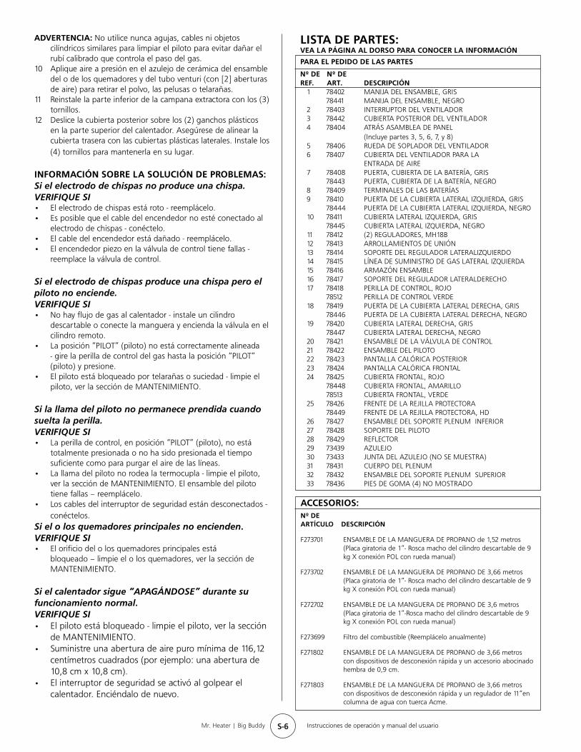
LISTA DE PARTES:VEA LA PÁGINA AL DORSO PARA CONOCER LA INFORMACIÓN
PARA EL PEDIDO DE LAS PARTES
Nº DE Nº DE REF. ART. DESCRIPCIÓN
1 78402 MANIJA DEL ENSAMBLE , GRIS 78441 MANIJA DEL ENSAMBLE , NEGRO2 78403 INTERRUPTOR DEL VENTILADOR 3 78442 CUBIERTA POSTERIOR DEL VENTILADOR 4 78404 ATRÁS ASAMBLEA DE PANEL (Incluye partes 3, 5, 6, 7, y 8)5 78406 RUEDA DE SOPLADOR DEL VENTILADOR 6 78407 CUBIERTA DEL VENTILADOR PARA LA ENTRADA DE AIRE 7 78408 PUERTA, CUBIERTA DE LA BATERÍA , GRIS 78443 PUERTA, CUBIERTA DE LA BATERÍA , NEGRO8 78409 TERMINALES DE LAS BATERÍAS 9 78410 PUERTA DE LA CUBIERTA LATERAL IZQUIERDA , GRIS 78444 PUERTA DE LA CUBIERTA LATERAL IZQUIERDA, NEGRO10 78411 CUBIERTA LATERAL IZQUIERDA , GRIS 78445 CUBIERTA LATERAL IZQUIERDA , NEGRO11 78412 (2) REGULADORES, MH18B 12 78413 ARROLLAMIENTOS DE UNIÓN 13 78414 SOPORTE DEL REGULADOR LATERALIZQUIERDO 14 78415 LÍNEA DE SUMINISTRO DE GAS LATERAL IZQUIERDA 15 78416 ARMAZÓN ENSAMBLE 16 78417 SOPORTE DEL REGULADOR LATERALDERECHO 17 78418 PERILLA DE CONTROL , ROJO 78512 PERILLA DE CONTROL VERDE18 78419 PUERTA DE LA CUBIERTA LATERAL DERECHA, GRIS 78446 PUERTA DE LA CUBIERTA LATERAL DERECHA, NEGRO19 78420 CUBIERTA LATERAL DERECHA, GRIS 78447 CUBIERTA LATERAL DERECHA, NEGRO20 78421 ENSAMBLE DE LA VÁLVULA DE CONTROL 21 78422 ENSAMBLE DEL PILOTO 22 78423 PANTALLA CALÓRICA POSTERIOR 23 78424 PANTALLA CALÓRICA FRONTAL 24 78425 CUBIERTA FRONTAL, ROJO 78448 CUBIERTA FRONTAL, AMARILLO 78513 CUBIERTA FRONTAL, VERDE25 78426 FRENTE DE LA REJILLA PROTECTORA 78449 FRENTE DE LA REJILLA PROTECTORA, HD26 78427 ENSAMBLE DEL SOPORTE PLENUM INFERIOR 27 78428 SOPORTE DEL PILOTO 28 78429 REFLECTOR 29 73439 AZULEJO 30 73433 JUNTA DEL AZULEJO (NO SE MUESTRA) 31 78431 CUERPO DEL PLENUM 32 78432 ENSAMBLE DEL SOPORTE PLENUM SUPERIOR 33 78436 PIES DE GOMA (4) NO MOSTRADO

S-7 Instrucciones de operación y manual del usuarioMr. Heater | Big Buddy
Mr.Heater•BigBuddy•NºdelmodeloMH18B
S-8 Instrucciones de operación y manual del usuarioMr. Heater | Big Buddy
Mr. Heater, INC., 4560 W. 160TH ST., CLEVELAND, OHIO 44135 • 216-916-3000Mr. Heater y Big Buddy son marcas registradas de Mr. Heater, Inc. ©2003, Enerco/Mr. Heater. Todos los derechos reservados
04/08 78438US Rev. D
MH18B
Modelo Nº INSTRUCCIONES DE OPERACIÓN Y MANUAL DEL USUARIO
ADVERTENCIA:USE SOLO LOS REPUESTOS DEL FABRICANTE. EL USO DE CUALQUIER OTRO REPUESTO PUEDE CAUSAR LESIONES O LA MUERTE. LOS REPUESTOS SÓLO ESTÁN DISPONIBLES DIRECTAMENTE DE FÁBRICA Y DEBEN SER INSTALADOS POR UNA AGENCIA DE REPARACIÓN CALIFICADA. LAS MANGUERAS MR. HEATER F273701, F273702, Y F272702 ESTÁN ESPECÍFICAMENTE DISEÑADAS PARA SER UTILIZADAS CON ESTE CALENTADOR CONJUNTAMENTE CON EL FILTRO DE COMBUSTIBLE DESCARTABLE F273699. (REEMPLÁCELO ANUALMENTE). EL USO DE OTRAS MANGUERAS PUEDE HACER QUE EL CALENTADOR NO FUNCIONE.
INFORMACION PARA EL PEDIDO DE LAS PARTES:COMO COMPRAR: Los accesorios se pueden comprar en cualquier tienda local Mr. Heater o directamente de fábrica.
PARA OBTENER INFORMACIÓN SOBRE LA REPARACIÓNLlame al número gratuito 800-251-0001 o visite www.mrheater.comEstamos abiertos de lunes a viernes de 8:30 AM – 5:00 PM, hora Este.Incluya el número del modelo, la fecha de compra y la descripción del problema en todas sus comunicaciones.
GARANTÍA LIMITADAMr. Heater, Inc. garantiza que sus calentadores y accesorios no presentan defectos de material ni de mano de obra por un período de 1 año a partir de la fecha de compra. Mr. Heater, Inc. reparará o remplazará este producto sin cargo si se prueba que presenta falla dentro del plazo de 1 año y es devuelto a Mr. Heater, Inc. a cargo del cliente con el comprobante de compra dentro del período de la garantía.Mr. Heater, Inc. se reserva el derecho de realizar cambios en cualquier momento, sin aviso u obligación, en los colores, las especificaciones, los accesorios, los materiales y los modelos.
Certificación CSA 4.98 EE.UU