Stanley J. Dapkunas 960-9 - NIST
264
Stanley J. Dapkunas 960-9 Surface Engineering Measurement Standards for Inorganic Materials NIST recommended practice guide Special Publication 960-9 National Institute of Standards and Technology Technology Administration U.S. Department of Commerce
Transcript of Stanley J. Dapkunas 960-9 - NIST
April 2005
Stanley J. Dapkunas
960-9
Surface EngineeringMeasurementStandards forInorganic Materials
SP 960-9 • Surface En
gin
eering
Measu
remen
t Stand
ards fo
r Ino
rgan
ic Materials
NI
ST
r
ec
om
me
nd
ed
p r a c t i c e g u i d e
SpecialPublication
960-9
NNaattiioonnaall IInnssttiittuuttee ooffSSttaannddaarrddss aanndd TTeecchhnnoollooggyyTechnology AdministrationU.S. Department of Commerce
7652_CVR.qxd 9/27/2005 11:56 AM Page 1

7652_CVR.qxd 9/27/2005 11:56 AM Page 2
Surface EngineeringMeasurementStandards forInorganic Materials
Stanley J. Dapkunas
Materials Science and Engineering Laboratory
April 2005
U.S. Department of CommerceCarlos Gutierrez, Secretary
Technology AdministrationPhillip J. Bond, Under Secretary for Technology
National Institute of Standards and TechnologyHratch G. Semerjian, Acting Director
Special Publication 960-9
NIST Recommended Practice Guide
7652_.qxd 9/27/2005 11:58 AM Page i
ii
Certain commercial entities, equipment, or materials may be identified in thisdocument in order to describe an experimental procedure or concept adequately.Such identification is not intended to imply recommendation or endorsement bythe National Institute of Standards and Technology, nor is it intended to implythat the entities, materials, or equipment are necessarily the best available for thepurpose.______________________________________
National Institute of Standards and TechnologySpecial Publication 960-9Natl. Inst. Stand. Technol.Spec. Publ. 960-9252 pages (April 2005)CODEN: NSPUE2U.S. GOVERNMENT PRINTING OFFICEWASHINGTON: 2005For sale by the Superintendent of DocumentsU.S. Government Printing OfficeInternet: bookstore.gpo.gov Phone: (202) 512-1800 Fax: (202) 512-2250Mail: Stop SSOP, Washington, DC 20402-0001
7652_.qxd 9/27/2005 11:58 AM Page ii
iii
Acknowledgements ♦
Acknowledgements
This Recommended Practice Guide has benefited from the assistance of severalindividuals at the National Institute of Standards and Technology (NIST) and ASMInternational, and specifically members of the ASM International Surface EngineeringCommittee. Staffs of the NIST Research Library and the National Center for Standardsand Certification at NIST, in particular, were critical in providing access to standardsdescribed in this publication. Ed Mai of the NIST Administrative Services Divisiongave valuable advice on formatting and information presentation that makes thisdocument accessible. His design of Figure 1 is greatly appreciated.
In addition to members of the Editorial Committee, Bill Scott and Fran Cverna of theASM International staff provided valuable perspectives.
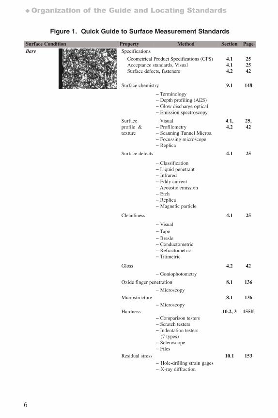
Photomicrographs in Figure 1 were originally published by ASM International. Theseillustrations of surface conditions clarify the organization of this Guide. Sources of thephotomicrographs are as follows:
Bare Material – ASM Micrograph Center On-Line Photo CS 1376Heat Treated – ASM Micrograph Center On-Line, Photo 0027Oxidized – ASM Micrograph Center On-Line CS 1079Carburized – ASM Micrograph Center On-Line Photo 0001Decarburized – ASM Micrograph Center On-Line Photo 0030Aluminized – ASM Handbook Volume 5, Surface Engineering, 1994, page 614,
Figure 3DChromized – ASM Metals Handbook, 8th Edition, Atlas of Microstructures of
Industrial Alloys, 1972, page 13, Photo 83Electroplated – ASM Metals Handbook, 8th Edition, Atlas of Microstructures of
Industrial Alloys, 1972, Photo 1877Galvanized/clad – ASM Metals Handbook, 8th Edition, Atlas of Microstructures of
Industrial Alloys, 1972, Photo 72Physical Vapor Deposition – ASM International, Journal of Thermal Spray Technology,
Vol. 6, No. 1, March 1988, page 37, Figure 5Thermal Sprayed – ASM International, Journal of Thermal Spray Technology, Vol. 6,
No. 1, March 1988, page 37, Figure 4
Figure 2. Applicability of Coating Thickness Measuring Methods, is reprinted, withpermission, from ASTM B 659-90(2003) Standard Guide for Measuring Thickness ofMetallic and Inorganic Coatings, copyright ASTM International, 100 Barr Harbor Drive,West Conshohocken, PA 19428.
7652_.qxd 9/27/2005 11:58 AM Page iii

iv
7652_.qxd 9/27/2005 11:58 AM Page iv
v
Preface ♦
Preface
Surface engineering of materials is important in applications as diverse as medicalimplants and gas turbines. Historically, a coating or cladding was added to a surface, ora surface was treated, to enhance properties or performance. However, increasingly, heattreated, implanted, coated and clad surfaces are viewed as part of a materials systemwhere the substrate and surface complement each other in achieving a performance goalfor a component. The integration of the surface and substrate as an engineered systemcreates a situation where failure of the surface may, in effect, be failure of the systemand thus characterization of surfaces and measurement of surface properties areimportant to the design, maintenance, and analysis of the whole system.
The advantages of engineered surfaces have stimulated development of surface treatmentand coating processes as well as materials and, consequently, commerce. Commerce inengineered materials depends upon the ability to specify and measure composition,microstructure, dimensions and properties as well as performance in applicationsof interest.
The intent of this Guide is to give the materials community a resource for identifyingstandard methods which are used to measure surface properties and to characterizesurface engineered materials.
This Guide has been prepared with the support of the Ceramics Division of the NationalInstitute of Standards and Technology and the cooperation of the Surface EngineeringCommittee of ASM International.
Specific thanks are due the Editorial Committee which oversaw this effort. Members ofthat committee include:
Professor Christopher C. Berndt, James Cook University, School of Engineering,Queensland, Australia; previously of Stony Brook University, Department of MaterialsScience and Engineering, Stony Brook, NY
Dr. Debra Kaiser, Chief, Ceramics Division, NIST, Gaithersburg, MD
Mr. Steven Lampman, ASM International, Materials Park, OH
Dr. James Treglio, Molecular Metallurgy, Inc., El Cahon. CA
ASM International generously provided the illustrative photomicrographs in Figure 1,Quick Guide to Surface Measurement Standards. Sources of specific photomicrographsare provided in the Acknowledgements section of this document.
ASTM International generously provided Figure 2, Applicability of Coating ThicknessMeasuring Methods. The source of Figure 2 is ASTM B 659-90 (2003) Standard Guidefor Measuring Thickness of Metallic and Inorganic Coatings.
More information on the SP 960 series can be found on the Internet athttp://www.nist.gov/practice guides. This website includes a complete list of NISTPractice Guides and ordering information.
7652_.qxd 9/27/2005 11:58 AM Page v

vi
7652_.qxd 9/27/2005 11:58 AM Page vi
vii
Table of Contents ♦
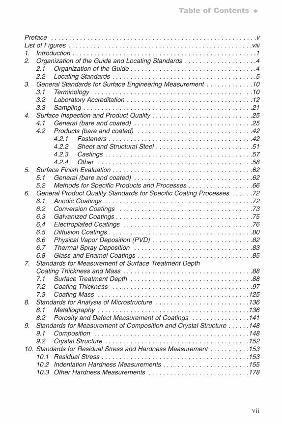
Preface . . . . . . . . . . . . . . . . . . . . . . . . . . . . . . . . . . . . . . . . . . . . . . . . . . . . . . . . .vList of Figures . . . . . . . . . . . . . . . . . . . . . . . . . . . . . . . . . . . . . . . . . . . . . . . . . . .viii1. Introduction . . . . . . . . . . . . . . . . . . . . . . . . . . . . . . . . . . . . . . . . . . . . . . . . . . .12. Organization of the Guide and Locating Standards . . . . . . . . . . . . . . . . . . . .4
2.1 Organization of the Guide . . . . . . . . . . . . . . . . . . . . . . . . . . . . . . . . . . .42.2 Locating Standards . . . . . . . . . . . . . . . . . . . . . . . . . . . . . . . . . . . . . . . .5
3. General Standards for Surface Engineering Measurement . . . . . . . . . . . . .103.1 Terminology . . . . . . . . . . . . . . . . . . . . . . . . . . . . . . . . . . . . . . . . . . . .103.2 Laboratory Accreditation . . . . . . . . . . . . . . . . . . . . . . . . . . . . . . . . . . .123.3 Sampling . . . . . . . . . . . . . . . . . . . . . . . . . . . . . . . . . . . . . . . . . . . . . . .21
4. Surface Inspection and Product Quality . . . . . . . . . . . . . . . . . . . . . . . . . . . .254.1 General (bare and coated) . . . . . . . . . . . . . . . . . . . . . . . . . . . . . . . . .254.2 Products (bare and coated) . . . . . . . . . . . . . . . . . . . . . . . . . . . . . . . .42
4.2.1 Fasteners . . . . . . . . . . . . . . . . . . . . . . . . . . . . . . . . . . . . . . . .424.2.2 Sheet and Structural Steel . . . . . . . . . . . . . . . . . . . . . . . . . . .514.2.3 Castings . . . . . . . . . . . . . . . . . . . . . . . . . . . . . . . . . . . . . . . . .574.2.4 Other . . . . . . . . . . . . . . . . . . . . . . . . . . . . . . . . . . . . . . . . . . .58
5. Surface Finish Evaluation . . . . . . . . . . . . . . . . . . . . . . . . . . . . . . . . . . . . . . .625.1 General (bare and coated) . . . . . . . . . . . . . . . . . . . . . . . . . . . . . . . . .625.2 Methods for Specific Products and Processes . . . . . . . . . . . . . . . . . .66
6. General Product Quality Standards for Specific Coating Processes . . . . . .726.1 Anodic Coatings . . . . . . . . . . . . . . . . . . . . . . . . . . . . . . . . . . . . . . . . .726.2 Conversion Coatings . . . . . . . . . . . . . . . . . . . . . . . . . . . . . . . . . . . . .736.3 Galvanized Coatings . . . . . . . . . . . . . . . . . . . . . . . . . . . . . . . . . . . . . .756.4 Electroplated Coatings . . . . . . . . . . . . . . . . . . . . . . . . . . . . . . . . . . . .766.5 Diffusion Coatings . . . . . . . . . . . . . . . . . . . . . . . . . . . . . . . . . . . . . . . .806.6 Physical Vapor Deposition (PVD) . . . . . . . . . . . . . . . . . . . . . . . . . . . .826.7 Thermal Spray Deposition . . . . . . . . . . . . . . . . . . . . . . . . . . . . . . . . .836.8 Glass and Enamel Coatings . . . . . . . . . . . . . . . . . . . . . . . . . . . . . . . .85
7. Standards for Measurement of Surface Treatment DepthCoating Thickness and Mass . . . . . . . . . . . . . . . . . . . . . . . . . . . . . . . . . . . .887.1 Surface Treatment Depth . . . . . . . . . . . . . . . . . . . . . . . . . . . . . . . . . .887.2 Coating Thickness . . . . . . . . . . . . . . . . . . . . . . . . . . . . . . . . . . . . . . .977.3 Coating Mass . . . . . . . . . . . . . . . . . . . . . . . . . . . . . . . . . . . . . . . . . .125
8. Standards for Analysis of Microstructure . . . . . . . . . . . . . . . . . . . . . . . . . .1368.1 Metallography . . . . . . . . . . . . . . . . . . . . . . . . . . . . . . . . . . . . . . . . . .1368.2 Porosity and Defect Measurement of Coatings . . . . . . . . . . . . . . . .141
9. Standards for Measurement of Composition and Crystal Structure . . . . . .1489.1 Composition . . . . . . . . . . . . . . . . . . . . . . . . . . . . . . . . . . . . . . . . . . .1489.2 Crystal Structure . . . . . . . . . . . . . . . . . . . . . . . . . . . . . . . . . . . . . . . .152
10. Standards for Residual Stress and Hardness Measurement . . . . . . . . . . .15310.1 Residual Stress . . . . . . . . . . . . . . . . . . . . . . . . . . . . . . . . . . . . . . . . .15310.2 Indentation Hardness Measurements . . . . . . . . . . . . . . . . . . . . . . . .15510.3 Other Hardness Measurements . . . . . . . . . . . . . . . . . . . . . . . . . . . .178
7652_.qxd 9/27/2005 11:58 AM Page vii
viii
♦Table of Contents
11. Standards for Mechanical Properties and Adhesion of Coatings . . . . . . . .18111.1 Mechanical Properties . . . . . . . . . . . . . . . . . . . . . . . . . . . . . . . . . . .18111.2 Adhesion . . . . . . . . . . . . . . . . . . . . . . . . . . . . . . . . . . . . . . . . . . . . . .187
12. Standards for Measurement of Corrosion, Wear and ThermalProperties . . . . . . . . . . . . . . . . . . . . . . . . . . . . . . . . . . . . . . . . . . . . . . . . . .19112.1 Bare . . . . . . . . . . . . . . . . . . . . . . . . . . . . . . . . . . . . . . . . . . . . . . . . .19112.2 Coated . . . . . . . . . . . . . . . . . . . . . . . . . . . . . . . . . . . . . . . . . . . . . . .198
13. Surface Engineering Measurement Standards . . . . . . . . . . . . . . . . . . . . .21013.1 ASME (American Society of Mechanical
Engineers) Standards . . . . . . . . . . . . . . . . . . . . . . . . . . . . . . . . . . . .21013.2 ASTM International (American Society for
Testing and Materials) Standards . . . . . . . . . . . . . . . . . . . . . . . . . . .21013.3 ISO (International Organization for
Standardization) Standards . . . . . . . . . . . . . . . . . . . . . . . . . . . . . . .21713.4 Military and Industry Standards . . . . . . . . . . . . . . . . . . . . . . . . . . . .22213.5 SAE (Society of Automotive Engineers) Standards . . . . . . . . . . . . .223
14. Index . . . . . . . . . . . . . . . . . . . . . . . . . . . . . . . . . . . . . . . . . . . . . . . . . . . . . .226
List of FiguresFigure 1. Quick Guide to Surface Measurement Standards . . . . . . . . . . . . . . . .6Figure 2. Applicability of Coating Thickness Measuring Methods . . . . . . . . . . .97
7652_.qxd 9/27/2005 11:58 AM Page viii
1
Introduction ♦
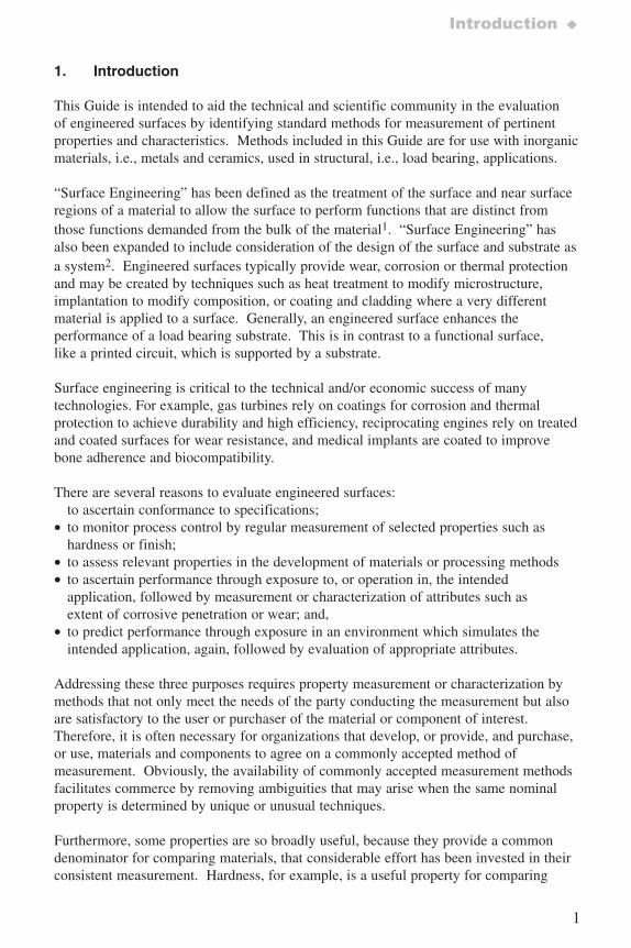
1. Introduction
This Guide is intended to aid the technical and scientific community in the evaluationof engineered surfaces by identifying standard methods for measurement of pertinentproperties and characteristics. Methods included in this Guide are for use with inorganicmaterials, i.e., metals and ceramics, used in structural, i.e., load bearing, applications.
“Surface Engineering” has been defined as the treatment of the surface and near surfaceregions of a material to allow the surface to perform functions that are distinct fromthose functions demanded from the bulk of the material1. “Surface Engineering” hasalso been expanded to include consideration of the design of the surface and substrate asa system2. Engineered surfaces typically provide wear, corrosion or thermal protectionand may be created by techniques such as heat treatment to modify microstructure,implantation to modify composition, or coating and cladding where a very differentmaterial is applied to a surface. Generally, an engineered surface enhances theperformance of a load bearing substrate. This is in contrast to a functional surface,like a printed circuit, which is supported by a substrate.
Surface engineering is critical to the technical and/or economic success of manytechnologies. For example, gas turbines rely on coatings for corrosion and thermalprotection to achieve durability and high efficiency, reciprocating engines rely on treatedand coated surfaces for wear resistance, and medical implants are coated to improvebone adherence and biocompatibility.
There are several reasons to evaluate engineered surfaces:to ascertain conformance to specifications;
• to monitor process control by regular measurement of selected properties such ashardness or finish;
• to assess relevant properties in the development of materials or processing methods• to ascertain performance through exposure to, or operation in, the intended
application, followed by measurement or characterization of attributes such asextent of corrosive penetration or wear; and,
• to predict performance through exposure in an environment which simulates theintended application, again, followed by evaluation of appropriate attributes.
Addressing these three purposes requires property measurement or characterization bymethods that not only meet the needs of the party conducting the measurement but alsoare satisfactory to the user or purchaser of the material or component of interest.Therefore, it is often necessary for organizations that develop, or provide, and purchase,or use, materials and components to agree on a commonly accepted method ofmeasurement. Obviously, the availability of commonly accepted measurement methodsfacilitates commerce by removing ambiguities that may arise when the same nominalproperty is determined by unique or unusual techniques.
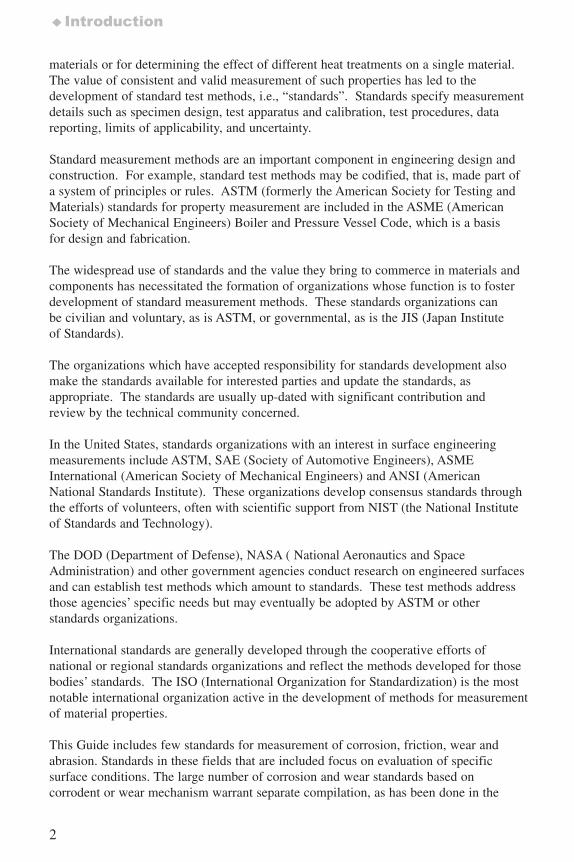
Furthermore, some properties are so broadly useful, because they provide a commondenominator for comparing materials, that considerable effort has been invested in theirconsistent measurement. Hardness, for example, is a useful property for comparing
7652_.qxd 9/27/2005 11:58 AM Page 1
2
♦Introduction
materials or for determining the effect of different heat treatments on a single material.The value of consistent and valid measurement of such properties has led to thedevelopment of standard test methods, i.e., “standards”. Standards specify measurementdetails such as specimen design, test apparatus and calibration, test procedures, datareporting, limits of applicability, and uncertainty.
Standard measurement methods are an important component in engineering design andconstruction. For example, standard test methods may be codified, that is, made part ofa system of principles or rules. ASTM (formerly the American Society for Testing andMaterials) standards for property measurement are included in the ASME (AmericanSociety of Mechanical Engineers) Boiler and Pressure Vessel Code, which is a basisfor design and fabrication.
The widespread use of standards and the value they bring to commerce in materials andcomponents has necessitated the formation of organizations whose function is to fosterdevelopment of standard measurement methods. These standards organizations canbe civilian and voluntary, as is ASTM, or governmental, as is the JIS (Japan Instituteof Standards).
The organizations which have accepted responsibility for standards development alsomake the standards available for interested parties and update the standards, asappropriate. The standards are usually up-dated with significant contribution andreview by the technical community concerned.
In the United States, standards organizations with an interest in surface engineeringmeasurements include ASTM, SAE (Society of Automotive Engineers), ASMEInternational (American Society of Mechanical Engineers) and ANSI (AmericanNational Standards Institute). These organizations develop consensus standards throughthe efforts of volunteers, often with scientific support from NIST (the National Instituteof Standards and Technology).
The DOD (Department of Defense), NASA ( National Aeronautics and SpaceAdministration) and other government agencies conduct research on engineered surfacesand can establish test methods which amount to standards. These test methods addressthose agencies’ specific needs but may eventually be adopted by ASTM or otherstandards organizations.
International standards are generally developed through the cooperative efforts ofnational or regional standards organizations and reflect the methods developed for thosebodies’ standards. The ISO (International Organization for Standardization) is the mostnotable international organization active in the development of methods for measurementof material properties.
This Guide includes few standards for measurement of corrosion, friction, wear andabrasion. Standards in these fields that are included focus on evaluation of specificsurface conditions. The large number of corrosion and wear standards based oncorrodent or wear mechanism warrant separate compilation, as has been done in the
7652_.qxd 9/27/2005 11:58 AM Page 2
3
Introduction ♦
“Friction and Wear Testing Source Book of Selected References from ASTM Standardsand ASM Handbooks”. That Source Book was issued jointly by ASTM Internationaland ASM International in 1997 and is available from those organizations.
Lastly, it is important to note that “standards”, i.e., standard test methods, are wellconsidered approaches to property measurement or material characterization and are theconsensus opinion of experienced practitioners and researchers. As such, they are ameans for those inexperienced in a specific field to quickly gain knowledge of what isregarded as a reputable measurement technique. Standard test methods do not alwaysinclude state-of-the-art techniques or address applications which are still in the researchstage and subject to rapid change.
This Guide does not provide details included in the standards identified and should notbe viewed as a substitute for those standards. Standards should be purchased from theissuing organization at the following addresses:
ASTM100 Barr Harbor DriveWest Conshocken, PA 19428-2959
ASMEThree Park AvenueNew York, NY 10016-5990
ISOCase postale 56CH-1211Geneva 20Switzerland
SAE International400 Commonwealth DriveWarrendale, PA 15096-0001
1 ASM Handbook, Volume 5, Surface Engineering, Copyright 1994 by ASMInternational, Materials Park, Ohio 44073-0002
2 http://www.twi.co.uk/j32/unprotected/band_1/surfaceengineering.htm
7652_.qxd 9/27/2005 11:58 AM Page 3
4
♦Organization of the Guide and Locating Standards
2. Organization of the Guide and Locating Standards
2.1 Organization of the Guide
This Guide is organized to enable rapid identification of standard measurement methods(“standards”) appropriate to the user’s interests.
The Guide includes standards appropriate for the following surface conditions:
• bare surfaces which have the same composition, phase and structure from surfaceto interior;
• treated surfaces wherein the base material has been subjected to conditions whichchange surface composition, structure, phase, or properties; and,
• coated surfaces wherein the base material has had specific additional materialdeposited on its surface, often significantly increasing the base material’s dimensions.
Treated surfaces are those that have been subjected to processes such as carburization,decarburization, nitridation, surface implantation, surface heat treatments and abrasiveblast hardening or cleaning.
Coated surfaces are those that have been covered with material having composition andproperties significantly different from the base material. Coating processes includeelectroplating, physical vapor deposition, thermal spray and galvanizing, for example.
The greatest part of this document consists of summaries of over 200 standards. A summary of each standard is provided in a template that includes the followinginformation, as appropriate:
• Standards Identification including issuing organization, standard identificationnumber and standard title;
• General Description including an overview of the method and the contents of thestandard;
• Intended Application including the stated purpose for which the standard wasdeveloped;
• Specimen Requirements including the size, condition or other characteristicsnecessary or valid use of the method;
• Data Produced including the nature of the data produced (visual or instrumentgenerated numeric, for example) and further refinements or calculationsnecessary, and,
• Limits of the method including inappropriate application, accuracy, precision orsafety concerns.
The templates are within Sections 3 through 12 of this Guide.Within each Section or Sub-section, standards are in the following order:• ASME Standards,• ASTM Standards,• ISO Standards,
7652_.qxd 9/27/2005 11:58 AM Page 4
5
Locating Standards ♦
• Military and Industry Standards, and• SAE Standards.
Sections 3 through 12 are organized as follows:• general aspects of surface inspection and product evaluation (Sections 3,4 and 5),• standards specific to selected coating processes (Section 6), and• standards for measurement of specific characteristics or properties (Sections 7
through 12).
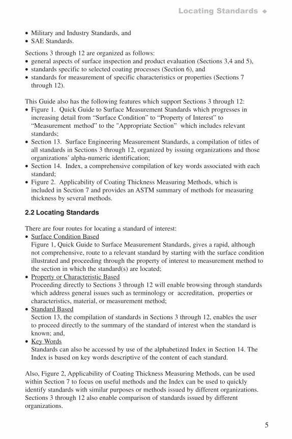
This Guide also has the following features which support Sections 3 through 12:• Figure 1. Quick Guide to Surface Measurement Standards which progresses in
increasing detail from “Surface Condition” to “Property of Interest” to“Measurement method” to the "Appropriate Section” which includes relevantstandards;
• Section 13. Surface Engineering Measurement Standards, a compilation of titles ofall standards in Sections 3 through 12, organized by issuing organizations and thoseorganizations’ alpha-numeric identification;
• Section 14. Index, a comprehensive compilation of key words associated with eachstandard;
• Figure 2. Applicability of Coating Thickness Measuring Methods, which isincluded in Section 7 and provides an ASTM summary of methods for measuringthickness by several methods.
2.2 Locating Standards
There are four routes for locating a standard of interest:• Surface Condition Based
Figure 1, Quick Guide to Surface Measurement Standards, gives a rapid, althoughnot comprehensive, route to a relevant standard by starting with the surface conditionillustrated and proceeding through the property of interest to measurement method tothe section in which the standard(s) are located;
• Property or Characteristic BasedProceeding directly to Sections 3 through 12 will enable browsing through standardswhich address general issues such as terminology or accreditation, properties orcharacteristics, material, or measurement method;
• Standard BasedSection 13, the compilation of standards in Sections 3 through 12, enables the userto proceed directly to the summary of the standard of interest when the standard isknown; and,
• Key WordsStandards can also be accessed by use of the alphabetized Index in Section 14. TheIndex is based on key words descriptive of the content of each standard.
Also, Figure 2, Applicability of Coating Thickness Measuring Methods, can be usedwithin Section 7 to focus on useful methods and the Index can be used to quicklyidentify standards with similar purposes or methods issued by different organizations.Sections 3 through 12 also enable comparison of standards issued by differentorganizations.
7652_.qxd 9/27/2005 11:58 AM Page 5
6
♦Organization of the Guide and Locating Standards
Figure 1. Quick Guide to Surface Measurement Standards
Surface Condition Property Method Section PageBare Specifications
Geometrical Product Specifications (GPS)Acceptance standards, VisualSurface defects, fasteners
4.14.14.2
252542
Surface chemistry 9.1 148
− Terminology− Depth profiling (AES)− Glow discharge optical− Emission spectroscopy
Surfaceprofile &texture
− Visual− Profilometry− Scanning Tunnel Micros.− Focussing microscope− Replica
4.1,4.2
25,42
Surface defects 4.1 25
− Classification− Liquid penetrant− Infrared− Eddy current− Acoustic emission− Etch− Replica− Magnetic particle
Cleanliness 4.1 25
− Visual− Tape− Bresle− Conductometric− Refractometric− Titimetric
Gloss 4.2 42
− Goniophotometry
Oxide finger penetration 8.1 136
− Microscopy
Microstructure 8.1 136− Microscopy
Hardness 10.2, 3 155ff− Comparison testers− Scratch testers− Indentation testers
(7 types)− Scleroscope− Files
Residual stress 10.1 153− Hole-drilling strain gages− X-ray diffraction
7652_.qxd 9/27/2005 11:58 AM Page 6
7
Locating Standards ♦
Figure 1. Quick Guide to Surface Measurement Standards (cont’d)
Surface Condition Property Method Section Page
Heat Treated Contractor accreditation 3.2 12
Case depth 7.1 88
− Hardness
Surface temper 4.2 42
− Etch inspection
Oxidized Oxide thickness 7.2 97
− Microscopy
Carburized Carburization depth 7.1 88
− Hardness− Microscopy
Decarburized Decarburization depth 7.1 88
− Hardness− Microscopy− Chemical
Anodized Sampling 3.3 21Thickness 7.2 97
− Gravimetric− Split beam microscopy
Aluminized Specification 6.5 80
Coating thickness 7.2 97
− Microscopy
Chromized Contractor accreditation 3.2 12
Coating thickness 7.2 97
− Microscopy
7652_.qxd 9/27/2005 11:58 AM Page 7
8
♦Organization of the Guide and Locating Standards
Figure 1. Quick Guide to Surface Measurement Standards (cont’d)
Surface Condition Property Method Section Page
Electroplated Sampling 3.2 12
Contractor accreditation 3.3 21
Coating thickness 7.2 97
− Coulometric− Magnetic− Acid dissolution− Beta backscatter− X-ray spectrometry− Interference microscopy− Microscopical− Eddy current− Profilometric− Radial sectioning
Coating mass, X-ray fluorescence 7.3 125
Grinding damage 4.1 25
Interfacial width, sputter depth profiling 9.1 148
Porosity, Gold 8.2 141
− Acid vapor− Paper electrography− Gel-bulk electrography− Sulfurous acid/sulfur dioxide− Flowers of sulfur
Gross defects & mechanical damage 8.2 141
− Polysulfide immersion
Hardness 10.2 155
− Knoop− Vickers
Ductility 11.1 181
− Bend test 11.2 187
Adhesion
Corrosion site characterization
− Interference microscopy 12.2 198
Hydrogen embrittlement
− Electronic 12.2 198
7652_.qxd 9/27/2005 11:58 AM Page 8
9
Locating Standards ♦
Figure 1. Quick Guide to Surface Measurement Standards (cont’d)
Surface Condition Property Method Section Page
Galvanized/Clad
Case study practices 6.3 75
Coating mass measurement 7.3 125
− Gravimetric− X-ray fluorescence− Triple spot
Composition 7.3 125
− Triple spot
PhysicalVaporDeposited
TiN Specification 6.6 82
Contractor accreditation 3.2 12
Coating thickness 7.2 97
− Microscopical− Radial sectioning
ThermalSprayed
Contractor accreditation 3.2 12
Specifications 6.7 83
Thickness 7.2 97
− Radial sectioning
Phase content, hydroxyapatite 9.2 152
− X-ray diffraction
Shear strength 11.1 181
− Mechanical
Tensile strength 11.1 181
− Mechanical
Fatigue strength 11.1 181
− Mechanical
Adhesion/cohesion strength 11.2 187
− Mechanical
Abrasion resistance 11.2 187
− Taber Abraser
7652_.qxd 9/27/2005 11:58 AM Page 9
10
♦General Standards for Surface Engineering
3. General Standards for Surface Engineering Measurement
3.1 Terminology
ASTM A 902Standard Terminology Relating to Metallic Coated Steel Products
General Description Data Produced
This Standard is a compilation of 47definitions of terms related to metalliccoatings used in the steel industry.The Standard also includesrecommended key words for ASTMCommittee A-5 Standards.
Not applicable/specified.
Intended Application Specimen Requirement Limits
Clarity of terminologyused in coated steelproduct descriptions.
Not specified. Not specified.
ISO 2079Surface Treatment and Metallic Coatings – General Classification of Terms
General Description Data Produced
This document provides general termsand definitions for several surfacetreatments and identifies relevantISO standards for those treatments.Terms and definitions are provided inEnglish, French, Russian andGerman.
Not specified.
Intended Application Specimen Requirement Limits
Intended to clarifyrelevant standards.
Not specified. Not specified.
7652_.qxd 9/27/2005 11:58 AM Page 10
11
Terminology ♦
ISO 2080Electroplating and Related Processes – Vocabulary
General Description Data Produced
This Standard provides definitions of804 terms used in electroplating andrelated processes such as metalfinishing. Definitions are in English,French, Russian and German.
Not specified.
Intended Application Specimen Requirement Limits
Intended to clarifyrelevant standards.
Not specified. Not specified.
SAE AS 4194Sheet and Strip Surface Finish Nomenclature(Aerospace Standard)
General Description Data Produced
Defines nomenclature for two surfaces(2D and 2B) of sheet and twosurfaces (No. 1 and No. 2) of stripmaterial and bright annealed finish.
Not specified/applicable.
Intended Application Specimen Requirement Limits
Provides explanations ofterms used to describesurface finish of iron,nickel, cobalt andtitanium base alloysused in aerospaceapplications.
Not specified/applicable. Not specified/applicable.
7652_.qxd 9/27/2005 11:58 AM Page 11
12
♦General Standards for Surface Engineering
3.2 Laboratory Accreditation
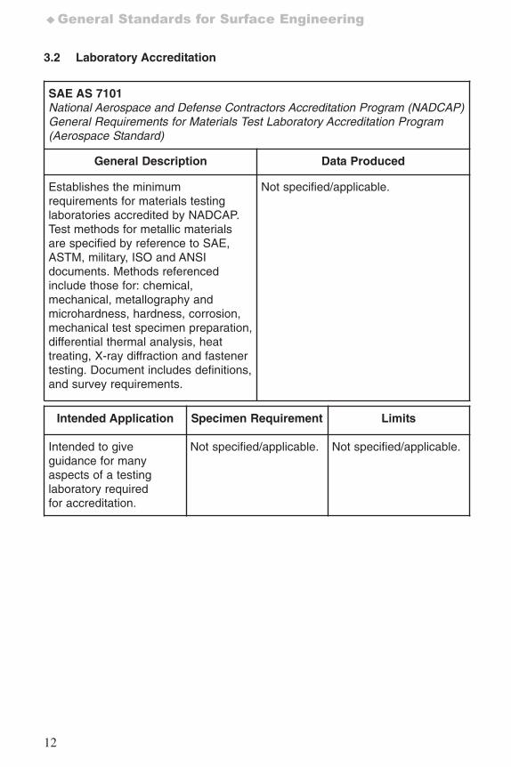
SAE AS 7101National Aerospace and Defense Contractors Accreditation Program (NADCAP)General Requirements for Materials Test Laboratory Accreditation Program (Aerospace Standard)
General Description Data Produced
Establishes the minimumrequirements for materials testinglaboratories accredited by NADCAP.Test methods for metallic materialsare specified by reference to SAE,ASTM, military, ISO and ANSIdocuments. Methods referencedinclude those for: chemical,mechanical, metallography andmicrohardness, hardness, corrosion,mechanical test specimen preparation,differential thermal analysis, heattreating, X-ray diffraction and fastenertesting. Document includes definitions,and survey requirements.
Not specified/applicable.
Intended Application Specimen Requirement Limits
Intended to giveguidance for manyaspects of a testinglaboratory requiredfor accreditation.
Not specified/applicable. Not specified/applicable.
7652_.qxd 9/27/2005 11:58 AM Page 12
13
Laboratory Accreditation ♦
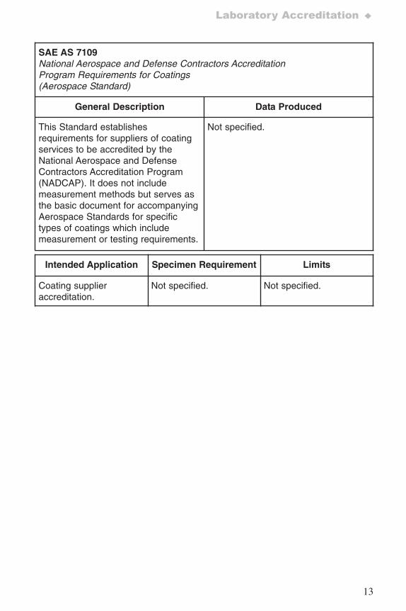
SAE AS 7109National Aerospace and Defense Contractors Accreditation Program Requirements for Coatings(Aerospace Standard)
General Description Data Produced
This Standard establishesrequirements for suppliers of coatingservices to be accredited by theNational Aerospace and DefenseContractors Accreditation Program(NADCAP). It does not includemeasurement methods but serves asthe basic document for accompanyingAerospace Standards for specifictypes of coatings which includemeasurement or testing requirements.
Not specified.
Intended Application Specimen Requirement Limits
Coating supplieraccreditation.
Not specified. Not specified.
7652_.qxd 9/27/2005 11:58 AM Page 13
14
♦General Standards for Surface Engineering
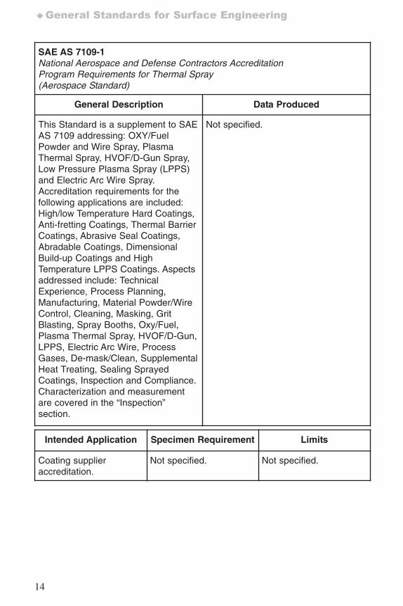
SAE AS 7109-1National Aerospace and Defense Contractors Accreditation Program Requirements for Thermal Spray(Aerospace Standard)
General Description Data Produced
This Standard is a supplement to SAEAS 7109 addressing: OXY/FuelPowder and Wire Spray, PlasmaThermal Spray, HVOF/D-Gun Spray,Low Pressure Plasma Spray (LPPS)and Electric Arc Wire Spray.Accreditation requirements for thefollowing applications are included:High/low Temperature Hard Coatings,Anti-fretting Coatings, Thermal BarrierCoatings, Abrasive Seal Coatings,Abradable Coatings, DimensionalBuild-up Coatings and HighTemperature LPPS Coatings. Aspectsaddressed include: TechnicalExperience, Process Planning,Manufacturing, Material Powder/WireControl, Cleaning, Masking, GritBlasting, Spray Booths, Oxy/Fuel,Plasma Thermal Spray, HVOF/D-Gun,LPPS, Electric Arc Wire, ProcessGases, De-mask/Clean, SupplementalHeat Treating, Sealing SprayedCoatings, Inspection and Compliance.Characterization and measurementare covered in the “Inspection”section.
Not specified.
Intended Application Specimen Requirement Limits
Coating supplieraccreditation.
Not specified. Not specified.
7652_.qxd 9/27/2005 11:58 AM Page 14
15
Laboratory Accreditation ♦
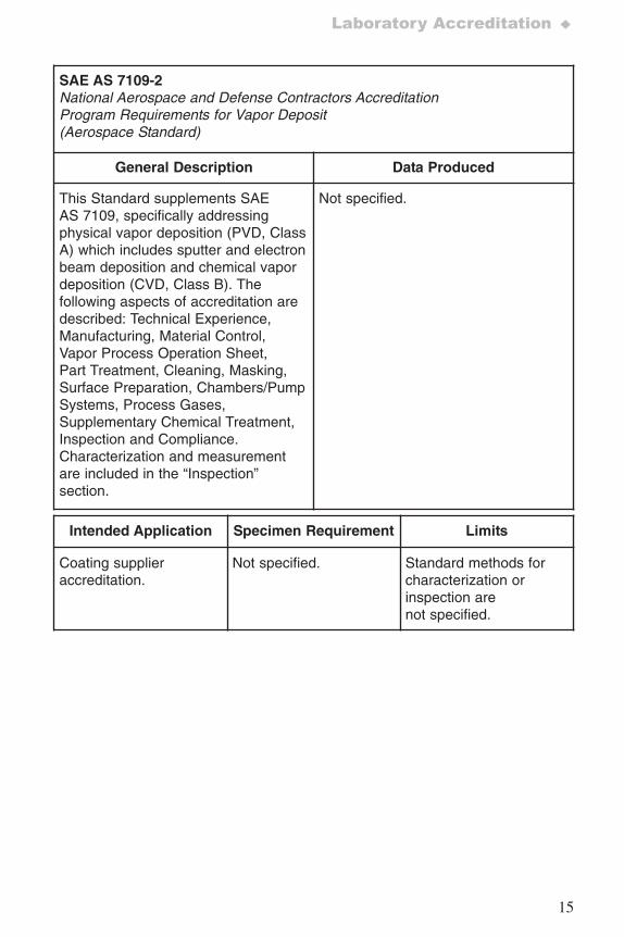
SAE AS 7109-2National Aerospace and Defense Contractors Accreditation Program Requirements for Vapor Deposit(Aerospace Standard)
General Description Data Produced
This Standard supplements SAEAS 7109, specifically addressingphysical vapor deposition (PVD, ClassA) which includes sputter and electronbeam deposition and chemical vapordeposition (CVD, Class B). Thefollowing aspects of accreditation aredescribed: Technical Experience,Manufacturing, Material Control,Vapor Process Operation Sheet,Part Treatment, Cleaning, Masking,Surface Preparation, Chambers/PumpSystems, Process Gases,Supplementary Chemical Treatment,Inspection and Compliance.Characterization and measurementare included in the “Inspection”section.
Not specified.
Intended Application Specimen Requirement Limits
Coating supplieraccreditation.
Not specified. Standard methods forcharacterization orinspection arenot specified.
7652_.qxd 9/27/2005 11:58 AM Page 15
16
♦General Standards for Surface Engineering
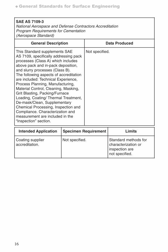
SAE AS 7109-3National Aerospace and Defense Contractors AccreditationProgram Requirements for Cementation(Aerospace Standard)
General Description Data Produced
This Standard supplements SAEAS 7109, specifically addressing packprocesses (Class A) which includesabove pack and in-pack deposition,and slurry processes (Class B).The following aspects of accreditationare included: Technical Experience,Process Planning, Manufacturing,Material Control, Cleaning, Masking,Grit Blasting, Packing/FurnaceLoading, Coating/ Thermal Treatment,De-mask/Clean, SupplementaryChemical Processing, Inspection andCompliance. Characterization andmeasurement are included in the“Inspection” section.
Not specified.
Intended Application Specimen Requirement Limits
Coating supplieraccreditation.
Not specified. Standard methods forcharacterization orinspection arenot specified.
7652_.qxd 9/27/2005 11:58 AM Page 16
17
Laboratory Accreditation ♦
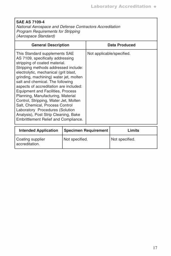
SAE AS 7109-4National Aerospace and Defense Contractors Accreditation Program Requirements for Stripping(Aerospace Standard)
General Description Data Produced
This Standard supplements SAEAS 7109, specifically addressingstripping of coated material.Stripping methods addressed include:electrolytic, mechanical (grit blast,grinding, machining) water jet, moltensalt and chemical. The followingaspects of accreditation are included:Equipment and Facilities, ProcessPlanning, Manufacturing, MaterialControl, Stripping, Water Jet, MoltenSalt, Chemical, Process ControlLaboratory Procedures (SolutionAnalysis), Post Strip Cleaning, BakeEmbrittlement Relief and Compliance.
Not applicable/specified.
Intended Application Specimen Requirement Limits
Coating supplieraccreditation.
Not specified. Not specified.
7652_.qxd 9/27/2005 11:58 AM Page 17
18
♦General Standards for Surface Engineering
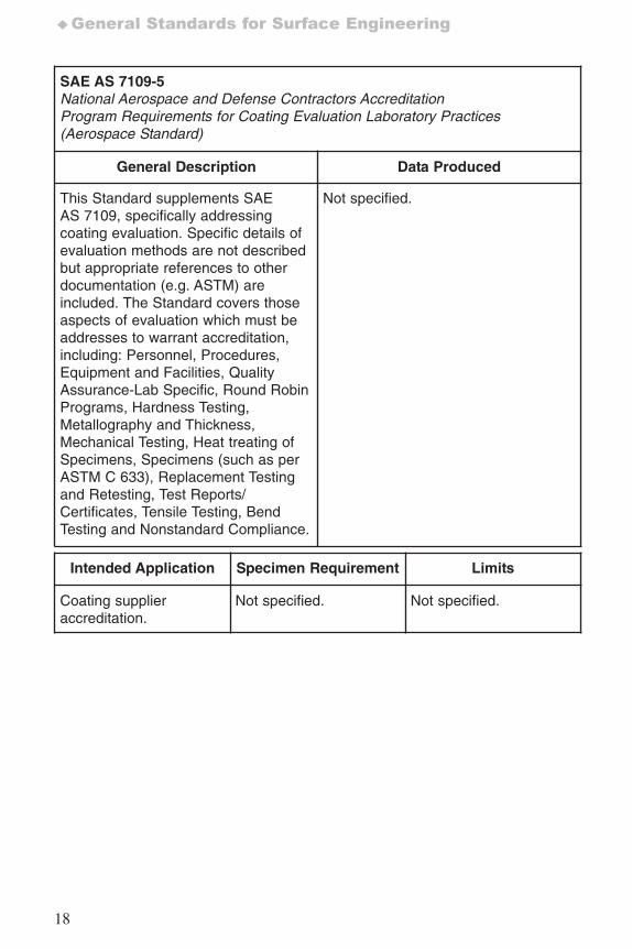
SAE AS 7109-5National Aerospace and Defense Contractors Accreditation Program Requirements for Coating Evaluation Laboratory Practices(Aerospace Standard)
General Description Data Produced
This Standard supplements SAEAS 7109, specifically addressingcoating evaluation. Specific details ofevaluation methods are not describedbut appropriate references to otherdocumentation (e.g. ASTM) areincluded. The Standard covers thoseaspects of evaluation which must beaddresses to warrant accreditation,including: Personnel, Procedures,Equipment and Facilities, QualityAssurance-Lab Specific, Round RobinPrograms, Hardness Testing,Metallography and Thickness,Mechanical Testing, Heat treating ofSpecimens, Specimens (such as perASTM C 633), Replacement Testingand Retesting, Test Reports/Certificates, Tensile Testing, BendTesting and Nonstandard Compliance.
Not specified.
Intended Application Specimen Requirement Limits
Coating supplieraccreditation.
Not specified. Not specified.
7652_.qxd 9/27/2005 11:58 AM Page 18
19
Laboratory Accreditation ♦
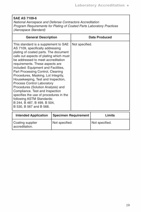
SAE AS 7109-6National Aerospace and Defense Contractors AccreditationProgram Requirements for Plating of Coated Parts Laboratory Practices(Aerospace Standard)
General Description Data Produced
This standard is a supplement to SAEAS 7109, specifically addressingplating of coated parts. The documentcalls out aspects of plating which mustbe addressed to meet accreditationrequirements. These aspects areincluded: Equipment and Facilities,Part Processing Control, CleaningProcedures, Masking, Lot Integrity,Housekeeping, Test and Inspection,Process Control LaboratoryProcedures (Solution Analysis) andCompliance. Test and Inspectionspecifies the use of procedures in thefollowing ASTM Standards:B 244, B 487, B 499, B 504,B 530, B 567 and B 568.
Not specified.
Intended Application Specimen Requirement Limits
Coating supplieraccreditation.
Not specified. Not specified.
7652_.qxd 9/27/2005 11:58 AM Page 19
20
♦General Standards for Surface Engineering
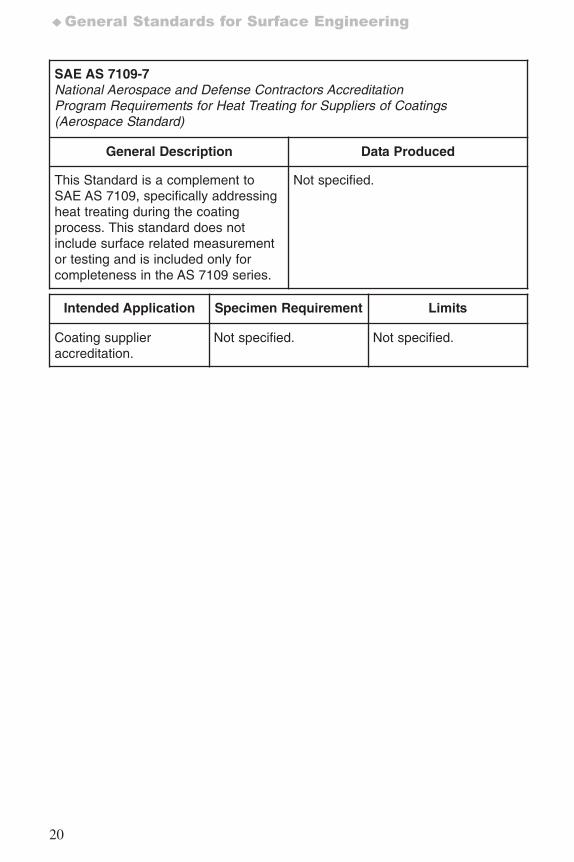
SAE AS 7109-7National Aerospace and Defense Contractors AccreditationProgram Requirements for Heat Treating for Suppliers of Coatings(Aerospace Standard)
General Description Data Produced
This Standard is a complement toSAE AS 7109, specifically addressingheat treating during the coatingprocess. This standard does notinclude surface related measurementor testing and is included only forcompleteness in the AS 7109 series.
Not specified.
Intended Application Specimen Requirement Limits
Coating supplieraccreditation.
Not specified. Not specified.
7652_.qxd 9/27/2005 11:58 AM Page 20
21
Sampling ♦
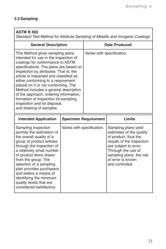
3.3 Sampling
ASTM B 602Standard Test Method for Attribute Sampling of Metallic and Inorganic Coatings
General Description Data Produced
This Method gives sampling plansintended for use in the inspection ofcoatings for conformance to ASTMspecifications. The plans are based oninspection by attributes. That is, thearticle is inspected and classified aseither conforming to a requirementplaced on it or not conforming. TheMethod includes a general descriptionof the approach, ordering information,formation of inspection lot,sampling,inspection and lot disposal,and drawing of samples.
Varies with specification.
Intended Application Specimen Requirement Limits
Sampling inspectionpermits the estimation ofthe overall quality of agroup of product articlesthrough the inspection ofa relatively small numberof product items drawnfrom the group. Theselection of a samplingplan provides purchasersand sellers a means ofidentifying the minimumquality levels that areconsidered satisfactory.
Varies with specification. Sampling plans yieldestimates of the qualityof product, thus theresults of the inspectionare subject to error.Through the use ofsampling plans, the riskof error is knownand controlled.
7652_.qxd 9/27/2005 11:58 AM Page 21
22
♦General Standards for Surface Engineering
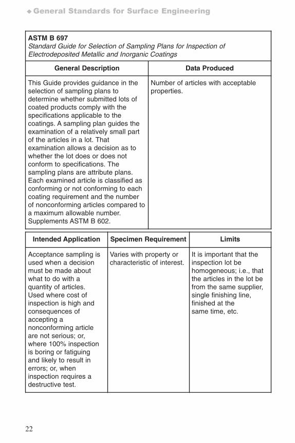
ASTM B 697Standard Guide for Selection of Sampling Plans for Inspection ofElectrodeposited Metallic and Inorganic Coatings
General Description Data Produced
This Guide provides guidance in theselection of sampling plans todetermine whether submitted lots ofcoated products comply with thespecifications applicable to thecoatings. A sampling plan guides theexamination of a relatively small partof the articles in a lot. Thatexamination allows a decision as towhether the lot does or does notconform to specifications. Thesampling plans are attribute plans.Each examined article is classified asconforming or not conforming to eachcoating requirement and the numberof nonconforming articles compared toa maximum allowable number.Supplements ASTM B 602.
Number of articles with acceptableproperties.
Intended Application Specimen Requirement Limits
Acceptance sampling isused when a decisionmust be made aboutwhat to do with aquantity of articles.Used where cost ofinspection is high andconsequences ofaccepting anonconforming articleare not serious; or,where 100% inspectionis boring or fatiguingand likely to result inerrors; or, wheninspection requires adestructive test.
Varies with property orcharacteristic of interest.
It is important that theinspection lot behomogeneous; i.e., thatthe articles in the lot befrom the same supplier,single finishing line,finished at thesame time, etc.
7652_.qxd 9/27/2005 11:58 AM Page 22
23
Sampling ♦
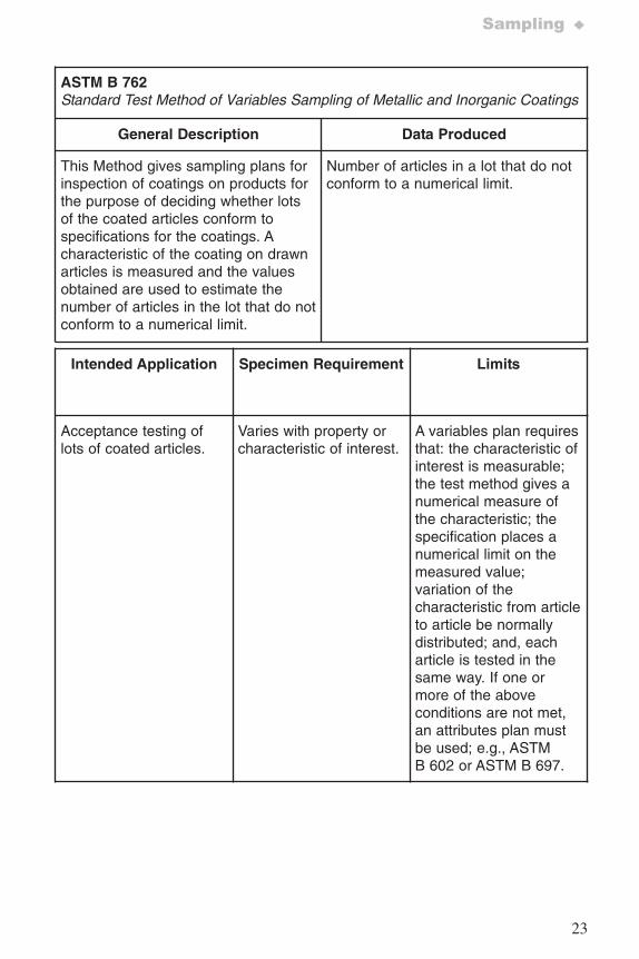
ASTM B 762Standard Test Method of Variables Sampling of Metallic and Inorganic Coatings
General Description Data Produced
This Method gives sampling plans forinspection of coatings on products forthe purpose of deciding whether lotsof the coated articles conform tospecifications for the coatings. Acharacteristic of the coating on drawnarticles is measured and the valuesobtained are used to estimate thenumber of articles in the lot that do notconform to a numerical limit.
Number of articles in a lot that do notconform to a numerical limit.
Intended Application Specimen Requirement Limits
Acceptance testing oflots of coated articles.
Varies with property orcharacteristic of interest.
A variables plan requiresthat: the characteristic ofinterest is measurable;the test method gives anumerical measure ofthe characteristic; thespecification places anumerical limit on themeasured value;variation of thecharacteristic from articleto article be normallydistributed; and, eacharticle is tested in thesame way. If one ormore of the aboveconditions are not met,an attributes plan mustbe used; e.g., ASTMB 602 or ASTM B 697.
7652_.qxd 9/27/2005 11:58 AM Page 23
24
♦General Standards for Surface Engineering
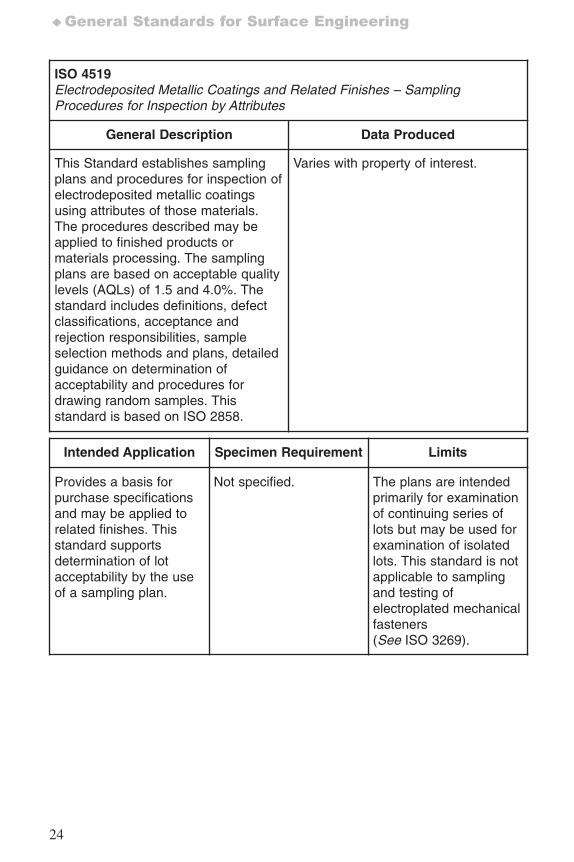
ISO 4519Electrodeposited Metallic Coatings and Related Finishes – SamplingProcedures for Inspection by Attributes
General Description Data Produced
This Standard establishes samplingplans and procedures for inspection ofelectrodeposited metallic coatingsusing attributes of those materials.The procedures described may beapplied to finished products ormaterials processing. The samplingplans are based on acceptable qualitylevels (AQLs) of 1.5 and 4.0%. Thestandard includes definitions, defectclassifications, acceptance andrejection responsibilities, sampleselection methods and plans, detailedguidance on determination ofacceptability and procedures fordrawing random samples. Thisstandard is based on ISO 2858.
Varies with property of interest.
Intended Application Specimen Requirement Limits
Provides a basis forpurchase specificationsand may be applied torelated finishes. Thisstandard supportsdetermination of lotacceptability by the useof a sampling plan.
Not specified. The plans are intendedprimarily for examinationof continuing series oflots but may be used forexamination of isolatedlots. This standard is notapplicable to samplingand testing ofelectroplated mechanicalfasteners(See ISO 3269).
7652_.qxd 9/27/2005 11:58 AM Page 24
25
General (bare and coated) ♦
4. Surface Inspection and Product Quality
4.1 General (bare and coated)
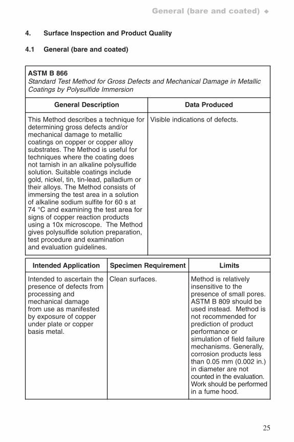
ASTM B 866 Standard Test Method for Gross Defects and Mechanical Damage in MetallicCoatings by Polysulfide Immersion
General Description Data Produced
This Method describes a technique fordetermining gross defects and/ormechanical damage to metalliccoatings on copper or copper alloysubstrates. The Method is useful fortechniques where the coating doesnot tarnish in an alkaline polysulfidesolution. Suitable coatings includegold, nickel, tin, tin-lead, palladium ortheir alloys. The Method consists ofimmersing the test area in a solutionof alkaline sodium sulfite for 60 s at74 °C and examining the test area forsigns of copper reaction productsusing a 10x microscope. The Methodgives polysulfide solution preparation,test procedure and examinationand evaluation guidelines.
Visible indications of defects.
Intended Application Specimen Requirement Limits
Intended to ascertain thepresence of defects fromprocessing andmechanical damagefrom use as manifestedby exposure of copperunder plate or copperbasis metal.
Clean surfaces. Method is relativelyinsensitive to thepresence of small pores.ASTM B 809 should beused instead. Method isnot recommended forprediction of productperformance orsimulation of field failuremechanisms. Generally,corrosion products lessthan 0.05 mm (0.002 in.)in diameter are notcounted in the evaluation.Work should be performedin a fume hood.
7652_.qxd 9/27/2005 11:58 AM Page 25
26
♦Surface Inspection and Product Quality
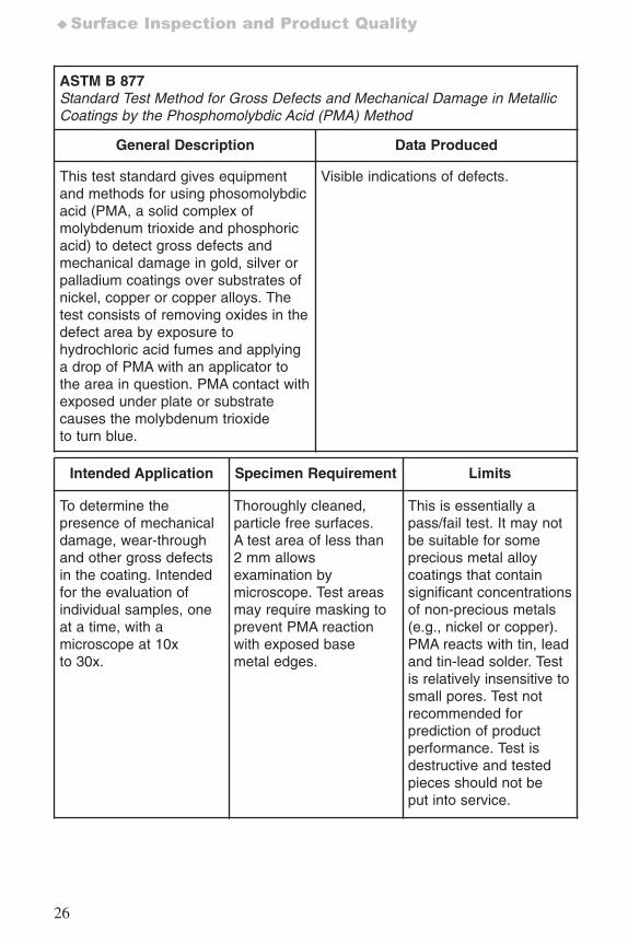
ASTM B 877Standard Test Method for Gross Defects and Mechanical Damage in MetallicCoatings by the Phosphomolybdic Acid (PMA) Method
General Description Data Produced
This test standard gives equipmentand methods for using phosomolybdicacid (PMA, a solid complex ofmolybdenum trioxide and phosphoricacid) to detect gross defects andmechanical damage in gold, silver orpalladium coatings over substrates ofnickel, copper or copper alloys. Thetest consists of removing oxides in thedefect area by exposure tohydrochloric acid fumes and applyinga drop of PMA with an applicator tothe area in question. PMA contact withexposed under plate or substratecauses the molybdenum trioxideto turn blue.
Visible indications of defects.
Intended Application Specimen Requirement Limits
To determine thepresence of mechanicaldamage, wear-throughand other gross defectsin the coating. Intendedfor the evaluation ofindividual samples, oneat a time, with amicroscope at 10xto 30x.
Thoroughly cleaned,particle free surfaces.A test area of less than2 mm allowsexamination bymicroscope. Test areasmay require masking toprevent PMA reactionwith exposed basemetal edges.
This is essentially apass/fail test. It may notbe suitable for someprecious metal alloycoatings that containsignificant concentrationsof non-precious metals(e.g., nickel or copper).PMA reacts with tin, leadand tin-lead solder. Testis relatively insensitive tosmall pores. Test notrecommended forprediction of productperformance. Test isdestructive and testedpieces should not beput into service.
7652_.qxd 9/27/2005 11:58 AM Page 26
27
General (bare and coated) ♦
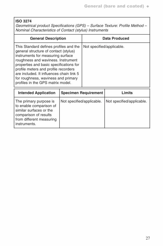
ISO 3274Geometrical product Specifications (GPS) – Surface Texture: Profile Method –Nominal Characteristics of Contact (stylus) Instruments
General Description Data Produced
This Standard defines profiles and thegeneral structure of contact (stylus)instruments for measuring surfaceroughness and waviness. Instrumentproperties and basic specifications forprofile meters and profile recordersare included. It influences chain link 5for roughness, waviness and primaryprofiles in the GPS matrix model.
Not specified/applicable.
Intended Application Specimen Requirement Limits
The primary purpose isto enable comparison ofsimilar surfaces or thecomparison of resultsfrom different measuringinstruments.
Not specified/applicable. Not specified/applicable.
7652_.qxd 9/27/2005 11:58 AM Page 27
28
♦Surface Inspection and Product Quality
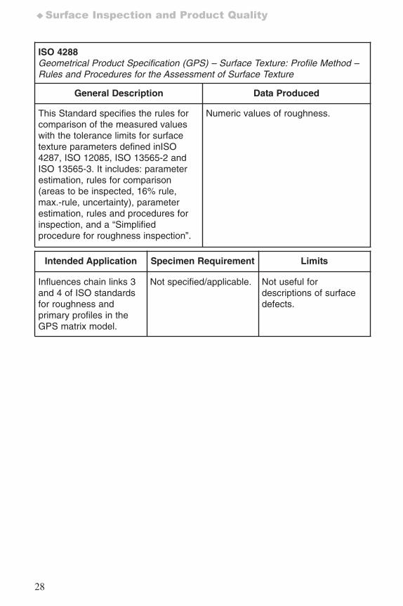
ISO 4288Geometrical Product Specification (GPS) – Surface Texture: Profile Method –Rules and Procedures for the Assessment of Surface Texture
General Description Data Produced
This Standard specifies the rules forcomparison of the measured valueswith the tolerance limits for surfacetexture parameters defined inISO4287, ISO 12085, ISO 13565-2 andISO 13565-3. It includes: parameterestimation, rules for comparison(areas to be inspected, 16% rule,max.-rule, uncertainty), parameterestimation, rules and procedures forinspection, and a “Simplifiedprocedure for roughness inspection”.
Numeric values of roughness.
Intended Application Specimen Requirement Limits
Influences chain links 3and 4 of ISO standardsfor roughness andprimary profiles in theGPS matrix model.
Not specified/applicable. Not useful fordescriptions of surfacedefects.
7652_.qxd 9/27/2005 11:58 AM Page 28
29
General (bare and coated) ♦
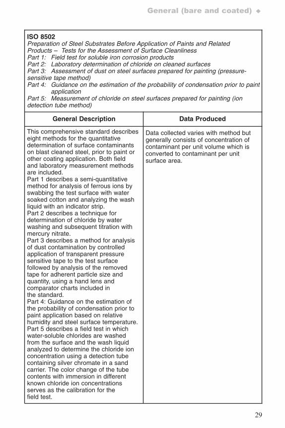
ISO 8502Preparation of Steel Substrates Before Application of Paints and RelatedProducts – Tests for the Assessment of Surface CleanlinessPart 1: Field test for soluble iron corrosion productsPart 2: Laboratory determination of chloride on cleaned surfacesPart 3: Assessment of dust on steel surfaces prepared for painting (pressure-sensitive tape method)Part 4: Guidance on the estimation of the probability of condensation prior to paint
applicationPart 5: Measurement of chloride on steel surfaces prepared for painting (ion detection tube method)
General Description Data Produced
This comprehensive standard describeseight methods for the quantitativedetermination of surface contaminantson blast cleaned steel, prior to paint orother coating application. Both fieldand laboratory measurement methodsare included.Part 1 describes a semi-quantitativemethod for analysis of ferrous ions byswabbing the test surface with watersoaked cotton and analyzing the washliquid with an indicator strip.Part 2 describes a technique fordetermination of chloride by waterwashing and subsequent titration withmercury nitrate.Part 3 describes a method for analysisof dust contamination by controlledapplication of transparent pressuresensitive tape to the test surfacefollowed by analysis of the removedtape for adherent particle size andquantity, using a hand lens andcomparator charts included inthe standard.Part 4: Guidance on the estimation ofthe probability of condensation prior topaint application based on relativehumidity and steel surface temperature.Part 5 describes a field test in whichwater-soluble chlorides are washedfrom the surface and the wash liquidanalyzed to determine the chloride ionconcentration using a detection tubecontaining silver chromate in a sandcarrier. The color change of the tubecontents with immersion in differentknown chloride ion concentrationsserves as the calibration for thefield test.
Data collected varies with method butgenerally consists of concentration ofcontaminant per unit volume which isconverted to contaminant per unitsurface area.
7652_.qxd 9/27/2005 11:58 AM Page 29
30
♦Surface Inspection and Product Quality
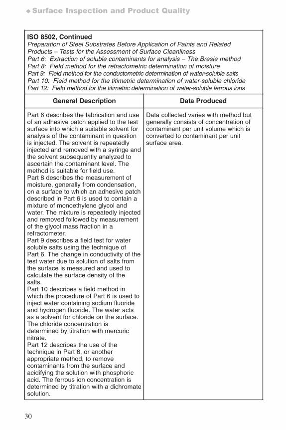
ISO 8502, ContinuedPreparation of Steel Substrates Before Application of Paints and RelatedProducts – Tests for the Assessment of Surface CleanlinessPart 6: Extraction of soluble contaminants for analysis – The Bresle methodPart 8: Field method for the refractometric determination of moisturePart 9: Field method for the conductometric determination of water-soluble saltsPart 10: Field method for the titimetric determination of water-soluble chloridePart 12: Field method for the titimetric determination of water-soluble ferrous ions
General Description Data Produced
Part 6 describes the fabrication and useof an adhesive patch applied to the testsurface into which a suitable solvent foranalysis of the contaminant in questionis injected. The solvent is repeatedlyinjected and removed with a syringe andthe solvent subsequently analyzed toascertain the contaminant level. Themethod is suitable for field use.Part 8 describes the measurement ofmoisture, generally from condensation,on a surface to which an adhesive patchdescribed in Part 6 is used to contain amixture of monoethylene glycol andwater. The mixture is repeatedly injectedand removed followed by measurementof the glycol mass fraction in arefractometer.Part 9 describes a field test for watersoluble salts using the technique ofPart 6. The change in conductivity of thetest water due to solution of salts fromthe surface is measured and used tocalculate the surface density of thesalts.Part 10 describes a field method inwhich the procedure of Part 6 is used toinject water containing sodium fluorideand hydrogen fluoride. The water actsas a solvent for chloride on the surface.The chloride concentration isdetermined by titration with mercuricnitrate. Part 12 describes the use of thetechnique in Part 6, or anotherappropriate method, to removecontaminants from the surface andacidifying the solution with phosphoricacid. The ferrous ion concentration isdetermined by titration with a dichromatesolution.
Data collected varies with method butgenerally consists of concentration ofcontaminant per unit volume which isconverted to contaminant per unitsurface area.
7652_.qxd 9/27/2005 11:58 AM Page 30
31
General (bare and coated) ♦
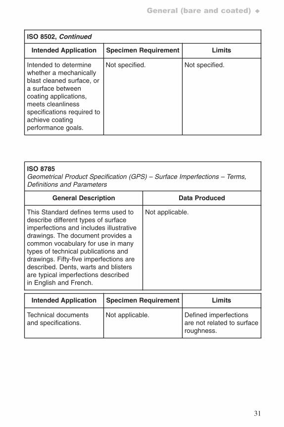
ISO 8502, Continued
Intended Application Specimen Requirement Limits
Intended to determinewhether a mechanicallyblast cleaned surface, ora surface betweencoating applications,meets cleanlinessspecifications required toachieve coatingperformance goals.
Not specified. Not specified.
ISO 8785Geometrical Product Specification (GPS) – Surface Imperfections – Terms,Definitions and Parameters
General Description Data Produced
This Standard defines terms used todescribe different types of surfaceimperfections and includes illustrativedrawings. The document provides acommon vocabulary for use in manytypes of technical publications anddrawings. Fifty-five imperfections aredescribed. Dents, warts and blistersare typical imperfections describedin English and French.
Not applicable.
Intended Application Specimen Requirement Limits
Technical documentsand specifications.
Not applicable. Defined imperfectionsare not related to surfaceroughness.
7652_.qxd 9/27/2005 11:58 AM Page 31
32
♦Surface Inspection and Product Quality
ISO 11562Geometrical Product Specifications (GPS) – Surface tTexture: Profile Method –Metrological Characteristics of Phase Correct Filters
General Description Data Produced
This Standard specifies themetrological characteristics of phasecorrect filters for measurement ofsurface profiles, particularly how toseparate the long and short wavecontent of a surface profile. Thedocument includes definitions ofrelevant terms, characteristics ofphase correct profile filters (includingtransmission characteristics of longand short wave profile components),limits of error of phase correct filters,and criteria for selection of phasecorrect filters. The relation of thisstandard to the GPS matrix modelis provided.
Roughness profile.
Intended Application Specimen Requirement Limits
Influences links 2 and 3in the chains ofstandards for primaryprofile in the GPSmatrix model.
Not specified/applicable. Not specified.
7652_.qxd 9/27/2005 11:58 AM Page 32
33
General (bare and coated) ♦
ISO 12085Geometrical Product Specification (GPS) – Surface Texture: Profile Method –Motif Parameters
General Description Data Produced
This Standard defines terms used inthe determination of surface texture bythe motif method and the motifmethod, including a calculationmethod for combination of motifs.Annexes provide information on therelation between motif parameters(roughness profile, waviness profileand primary profile) and function ofsurfaces as well as the relation of thestandard to the GPS matrix model.
Quantifiable roughness profilerepresentation.
Intended Application Specimen Requirement Limits
Influences links 2, 3 and4 of the surface texturechain of standards onroughness and wavinessprofile in the GPSmatrix model.
Not specified/applicable. Not specified.
7652_.qxd 9/27/2005 11:58 AM Page 33
34
♦Surface Inspection and Product Quality
ISO 13565-1 Geometrical Product Specifications (GPS) – Surface Texture: Profile Method –Surfaces Having Stratified Functional PropertiesPart 1: Filtering and general measurement conditions
General Description Data Produced
This Standard describes a filteringmethod for description of surfaces thathave deep valleys underlying a finelyfinished plateau with a small amountof waviness. ISO 11562, bycomparison, describes a referenceline undesirably influenced by thepresence of valleys. ISO 13565-1provides a filtering approach thatsuppresses the valley influence on thereference line. This Standardaddresses surfaces common ininternal combustion cylinder liners.The filtering process to determine theroughness profile, selection of cut-offwavelength and the evaluation lengthand relation to the GPS matrixmodel are included.
Quantifiable roughness profilerepresentation.
Intended Application Specimen Requirement Limits
This Standard influenceslinks 2 and 3 in the chainof standards forroughness profile in theGPS matrix model.
Not specified. Not specified.
7652_.qxd 9/27/2005 11:58 AM Page 34
35
General (bare and coated) ♦
ISO 13565-2Geometrical Product Specifications (GPS) – Surface Texture: Profile Method –Surfaces Having Stratified functional PropertiesPart 2: Height characterization using the linear material ratio curve
General Description Data Produced
This document defines parametersbased on the linear material ratiocurve for the evaluation of the valleysuppressed roughness profile definedin ISO 13565-1. The Standardincludes determination of parameters,covering roughness profile, calculatingequivalent straight line, andcalculation of parameters forthe material ratio curve.
Quantifiable roughness profilerepresentation.
Intended Application Specimen Requirement Limits
This Standard addresseschain link 2 forroughness profile in theGeneral GPS matrix.
Not specified. Not specified.
7652_.qxd 9/27/2005 11:58 AM Page 35
36
♦Surface Inspection and Product Quality
ISO 13565-3Geometrical Product Specifications(GPS) – Surface Texture: Profile Method –Surfaces Having Stratified Functional PropertiesPart 3: Height characterization using the material probability curve
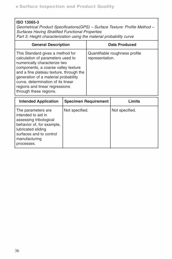
General Description Data Produced
This Standard gives a method forcalculation of parameters used tonumerically characterize twocomponents, a coarse valley textureand a fine plateau texture, through thegeneration of a material probabilitycurve, determination of its linearregions and linear regressionsthrough these regions.
Quantifiable roughness profilerepresentation.
Intended Application Specimen Requirement Limits
The parameters areintended to aid inassessing tribologicalbehavior of, for example,lubricated slidingsurfaces and to controlmanufacturingprocesses.
Not specified. Not specified.
7652_.qxd 9/27/2005 11:58 AM Page 36
37
General (bare and coated) ♦
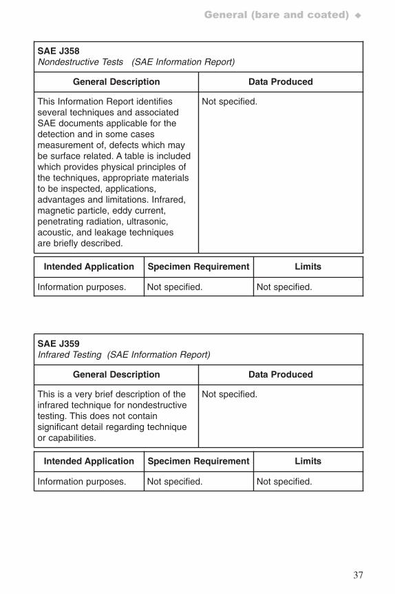
SAE J358 Nondestructive Tests (SAE Information Report)
General Description Data Produced
This Information Report identifiesseveral techniques and associatedSAE documents applicable for thedetection and in some casesmeasurement of, defects which maybe surface related. A table is includedwhich provides physical principles ofthe techniques, appropriate materialsto be inspected, applications,advantages and limitations. Infrared,magnetic particle, eddy current,penetrating radiation, ultrasonic,acoustic, and leakage techniquesare briefly described.
Not specified.
Intended Application Specimen Requirement Limits
Information purposes. Not specified. Not specified.
SAE J359 Infrared Testing (SAE Information Report)
General Description Data Produced
This is a very brief description of theinfrared technique for nondestructivetesting. This does not containsignificant detail regarding techniqueor capabilities.
Not specified.
Intended Application Specimen Requirement Limits
Information purposes. Not specified. Not specified.
7652_.qxd 9/27/2005 11:58 AM Page 37
38
♦Surface Inspection and Product Quality
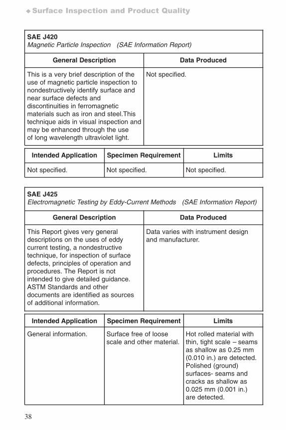
SAE J420Magnetic Particle Inspection (SAE Information Report)
General Description Data Produced
This is a very brief description of theuse of magnetic particle inspection tonondestructively identify surface andnear surface defects anddiscontinuities in ferromagneticmaterials such as iron and steel.Thistechnique aids in visual inspection andmay be enhanced through the useof long wavelength ultraviolet light.
Not specified.
Intended Application Specimen Requirement Limits
Not specified. Not specified. Not specified.
SAE J425Electromagnetic Testing by Eddy-Current Methods (SAE Information Report)
General Description Data Produced
This Report gives very generaldescriptions on the uses of eddycurrent testing, a nondestructivetechnique, for inspection of surfacedefects, principles of operation andprocedures. The Report is notintended to give detailed guidance.ASTM Standards and otherdocuments are identified as sourcesof additional information.
Data varies with instrument designand manufacturer.
Intended Application Specimen Requirement Limits
General information. Surface free of loosescale and other material.
Hot rolled material withthin, tight scale – seamsas shallow as 0.25 mm(0.010 in.) are detected.Polished (ground)surfaces- seams andcracks as shallow as0.025 mm (0.001 in.)are detected.
7652_.qxd 9/27/2005 11:58 AM Page 38
39
General (bare and coated) ♦
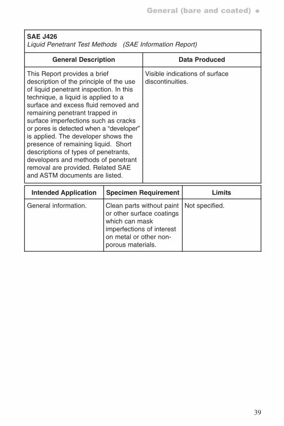
SAE J426 Liquid Penetrant Test Methods (SAE Information Report)
General Description Data Produced
This Report provides a briefdescription of the principle of the useof liquid penetrant inspection. In thistechnique, a liquid is applied to asurface and excess fluid removed andremaining penetrant trapped insurface imperfections such as cracksor pores is detected when a “developer”is applied. The developer shows thepresence of remaining liquid. Shortdescriptions of types of penetrants,developers and methods of penetrantremoval are provided. Related SAEand ASTM documents are listed.
Visible indications of surfacediscontinuities.
Intended Application Specimen Requirement Limits
General information. Clean parts without paintor other surface coatingswhich can maskimperfections of intereston metal or other non-porous materials.
Not specified.
7652_.qxd 9/27/2005 11:58 AM Page 39
40
♦Surface Inspection and Product Quality
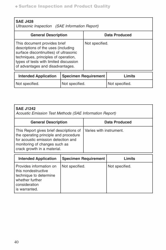
SAE J428 Ultrasonic Inspection (SAE Information Report)
General Description Data Produced
This document provides briefdescriptions of the uses (includingsurface discontinuities) of ultrasonictechniques, principles of operation,types of tests with limited discussionof advantages and disadvantages.
Not specified.
Intended Application Specimen Requirement Limits
Not specified. Not specified. Not specified.
SAE J1242 Acoustic Emission Test Methods (SAE Information Report)
General Description Data Produced
This Report gives brief descriptions ofthe operating principle and procedurefor acoustic emission detection andmonitoring of changes such ascrack growth in a material.
Varies with instrument.
Intended Application Specimen Requirement Limits
Provides information onthis nondestructivetechnique to determinewhether furtherconsiderationis warranted.
Not specified. Not specified.
7652_.qxd 9/27/2005 11:58 AM Page 40
41
General (bare and coated) ♦
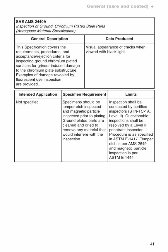
SAE AMS 2440AInspection of Ground, Chromium Plated Steel Parts (Aerospace Material Specification)
General Description Data Produced
This Specification covers therequirements, procedures, andacceptance/rejection criteria forinspecting ground chromium platedsurfaces for grinder induced damageto the chromium plate substructure.Examples of damage revealed byfluorescent dye inspectionare provided.
Visual appearance of cracks whenviewed with black light.
Intended Application Specimen Requirement Limits
Not specified. Specimens should betemper etch inspectedand magnetic particleinspected prior to plating.Ground plated parts arecleaned and dried toremove any material thatwould interfere with theinspection.
Inspection shall beconducted by certifiedinspectors (STN-TC-1A,Level II). Questionableinspections shall beresolved by a Level IIIpenetrant inspector.Procedure is as specifiedin ASTM E-1417. Temperetch is per AMS 2649and magnetic particleinspection is perASTM E 1444.
7652_.qxd 9/27/2005 11:58 AM Page 41
42
♦Surface Inspection and Product Quality
4.2 Products (bare and coated)
4.2.1 Fasteners
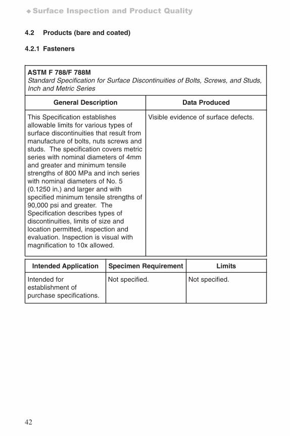
ASTM F 788/F 788M Standard Specification for Surface Discontinuities of Bolts, Screws, and Studs,Inch and Metric Series
General Description Data Produced
This Specification establishesallowable limits for various types ofsurface discontinuities that result frommanufacture of bolts, nuts screws andstuds. The specification covers metricseries with nominal diameters of 4mmand greater and minimum tensilestrengths of 800 MPa and inch serieswith nominal diameters of No. 5(0.1250 in.) and larger and withspecified minimum tensile strengths of90,000 psi and greater. TheSpecification describes types ofdiscontinuities, limits of size andlocation permitted, inspection andevaluation. Inspection is visual withmagnification to 10x allowed.
Visible evidence of surface defects.
Intended Application Specimen Requirement Limits
Intended forestablishment ofpurchase specifications.
Not specified. Not specified.
7652_.qxd 9/27/2005 11:58 AM Page 42
43
Products (bare and coated) ♦
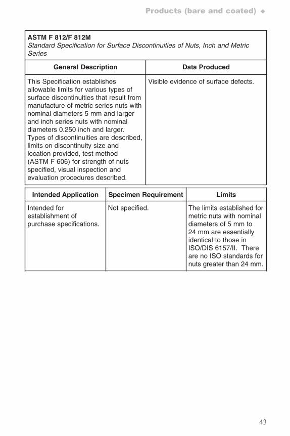
ASTM F 812/F 812MStandard Specification for Surface Discontinuities of Nuts, Inch and MetricSeries
General Description Data Produced
This Specification establishesallowable limits for various types ofsurface discontinuities that result frommanufacture of metric series nuts withnominal diameters 5 mm and largerand inch series nuts with nominaldiameters 0.250 inch and larger.Types of discontinuities are described,limits on discontinuity size andlocation provided, test method(ASTM F 606) for strength of nutsspecified, visual inspection andevaluation procedures described.
Visible evidence of surface defects.
Intended Application Specimen Requirement Limits
Intended forestablishment ofpurchase specifications.
Not specified. The limits established formetric nuts with nominaldiameters of 5 mm to24 mm are essentiallyidentical to those inISO/DIS 6157/II. Thereare no ISO standards fornuts greater than 24 mm.
7652_.qxd 9/27/2005 11:58 AM Page 43
44
♦Surface Inspection and Product Quality
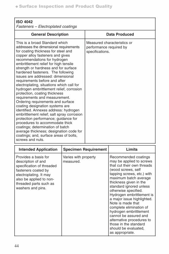
ISO 4042 Fasteners – Electroplated coatings
General Description Data Produced
This is a broad Standard whichaddresses the dimensional requirementsfor coating thickness for steel andcopper alloy fasteners and givesrecommendations for hydrogenembrittlement relief for high tensilestrength or hardness and for surfacehardened fasteners. The followingissues are addressed: dimensionalrequirements before and afterelectroplating, situations which call forhydrogen embrittlement relief, corrosionprotection, coating thicknessrequirements and measurement.Ordering requirements and surfacecoating designation systems areidentified. Annexes address: hydrogenembrittlement relief; salt spray corrosionprotection performance; guidance forprocedures to accommodate thickcoatings; determination of batchaverage thickness; designation code forcoatings; and, surface areas of bolts,screws and nuts.
Measured characteristics orperformance required byspecifications.
Intended Application Specimen Requirement Limits
Provides a basis fordescription of andspecification of threadedfasteners coated byelectroplating. It mayalso be applied to non-threaded parts such aswashers and pins.
Varies with propertymeasured.
Recommended coatingsmay be applied to screwsthat cut their own threads(wood screws, selftapping screws, etc.) withmaximum batch averagethickness given in thestandard ignored unlessotherwise specified.Hydrogen embrittlement isa major issue highlighted.Note is made thatcomplete elimination ofhydrogen embrittlementcannot be assured andalternative procedures tothose in the standardshould be evaluated,as appropriate.
7652_.qxd 9/27/2005 11:58 AM Page 44
45
Products (bare and coated) ♦
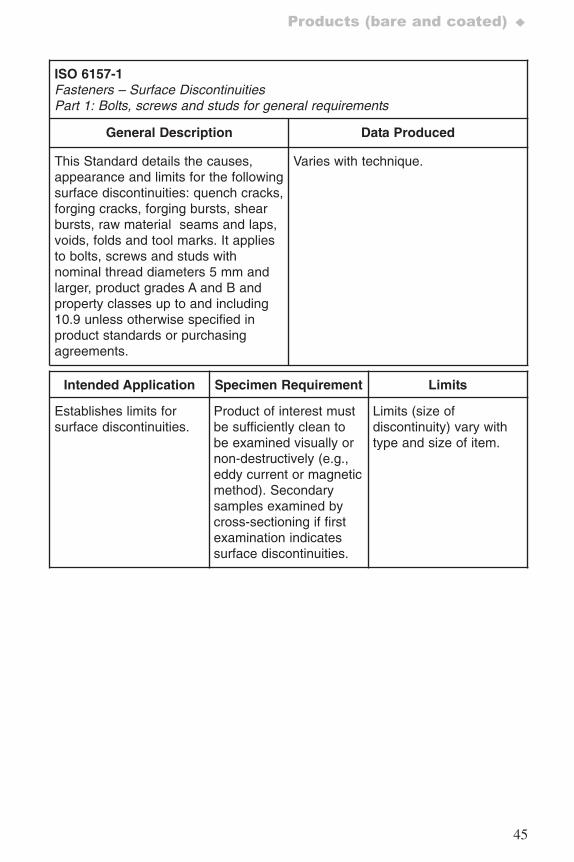
ISO 6157-1Fasteners – Surface DiscontinuitiesPart 1: Bolts, screws and studs for general requirements
General Description Data Produced
This Standard details the causes,appearance and limits for the followingsurface discontinuities: quench cracks,forging cracks, forging bursts, shearbursts, raw material seams and laps,voids, folds and tool marks. It appliesto bolts, screws and studs withnominal thread diameters 5 mm andlarger, product grades A and B andproperty classes up to and including10.9 unless otherwise specified inproduct standards or purchasingagreements.
Varies with technique.
Intended Application Specimen Requirement Limits
Establishes limits forsurface discontinuities.
Product of interest mustbe sufficiently clean tobe examined visually ornon-destructively (e.g.,eddy current or magneticmethod). Secondarysamples examined bycross-sectioning if firstexamination indicatessurface discontinuities.
Limits (size ofdiscontinuity) vary withtype and size of item.
7652_.qxd 9/27/2005 11:58 AM Page 45
46
♦Surface Inspection and Product Quality
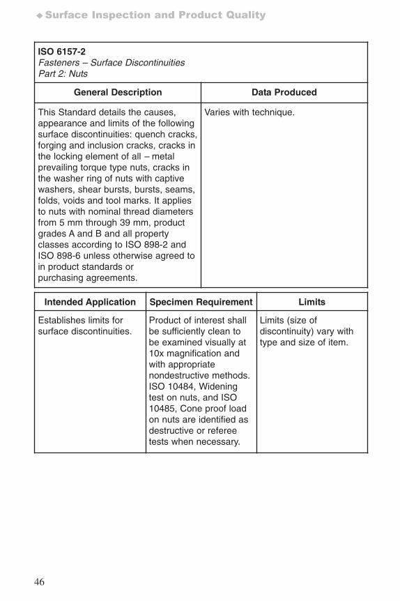
ISO 6157-2Fasteners – Surface DiscontinuitiesPart 2: Nuts
General Description Data Produced
This Standard details the causes,appearance and limits of the followingsurface discontinuities: quench cracks,forging and inclusion cracks, cracks inthe locking element of all – metalprevailing torque type nuts, cracks inthe washer ring of nuts with captivewashers, shear bursts, bursts, seams,folds, voids and tool marks. It appliesto nuts with nominal thread diametersfrom 5 mm through 39 mm, productgrades A and B and all propertyclasses according to ISO 898-2 andISO 898-6 unless otherwise agreed toin product standards orpurchasing agreements.
Varies with technique.
Intended Application Specimen Requirement Limits
Establishes limits forsurface discontinuities.
Product of interest shallbe sufficiently clean tobe examined visually at10x magnification andwith appropriatenondestructive methods.ISO 10484, Wideningtest on nuts, and ISO10485, Cone proof loadon nuts are identified asdestructive or refereetests when necessary.
Limits (size ofdiscontinuity) vary withtype and size of item.
7652_.qxd 9/27/2005 11:58 AM Page 46
47
Products (bare and coated) ♦
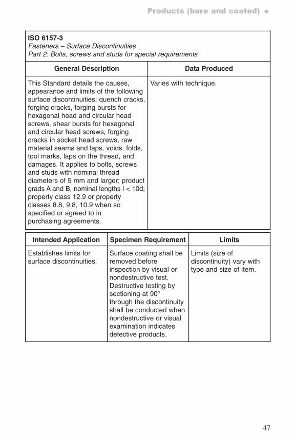
ISO 6157-3Fasteners – Surface DiscontinuitiesPart 2: Bolts, screws and studs for special requirements
General Description Data Produced
This Standard details the causes,appearance and limits of the followingsurface discontinuities: quench cracks,forging cracks, forging bursts forhexagonal head and circular headscrews, shear bursts for hexagonaland circular head screws, forgingcracks in socket head screws, rawmaterial seams and laps, voids, folds,tool marks, laps on the thread, anddamages. It applies to bolts, screwsand studs with nominal threaddiameters of 5 mm and larger; productgrads A and B, nominal lengths l < 10d;property class 12.9 or propertyclasses 8.8, 9.8, 10.9 when sospecified or agreed to inpurchasing agreements.
Varies with technique.
Intended Application Specimen Requirement Limits
Establishes limits forsurface discontinuities.
Surface coating shall beremoved beforeinspection by visual ornondestructive test.Destructive testing bysectioning at 90°through the discontinuityshall be conducted whennondestructive or visualexamination indicatesdefective products.
Limits (size ofdiscontinuity) vary withtype and size of item.
7652_.qxd 9/27/2005 11:58 AM Page 47
48
♦Surface Inspection and Product Quality
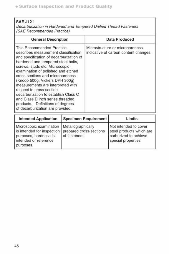
SAE J121 Decarburization in Hardened and Tempered Unified Thread Fasteners(SAE Recommended Practice)
General Description Data Produced
This Recommended Practicedescribes measurement classificationand specification of decarburization ofhardened and tempered steel bolts,screws, studs etc. Microscopicexamination of polished and etchedcross-sections and microhardness(Knoop 500g, Vickers DPH 300g)measurements are interpreted withrespect to cross-sectiondecarburization to establish Class Cand Class D inch series threadedproducts. Definitions of degreesof decarburization are provided.
Microstructure or microhardnessindicative of carbon content changes.
Intended Application Specimen Requirement Limits
Microscopic examinationis intended for inspectionpurposes, hardness isintended or referencepurposes.
Metallographicallyprepared cross-sectionsof fasteners.
Not intended to coversteel products which arecarburized to achievespecial properties.
7652_.qxd 9/27/2005 11:58 AM Page 48
49
Products (bare and coated) ♦
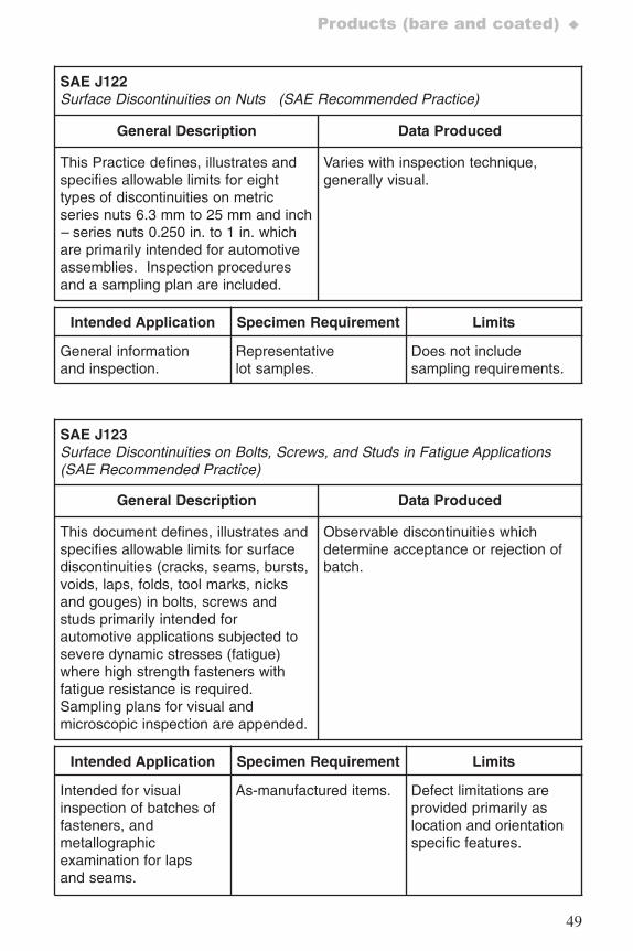
SAE J122 Surface Discontinuities on Nuts (SAE Recommended Practice)
General Description Data Produced
This Practice defines, illustrates andspecifies allowable limits for eighttypes of discontinuities on metricseries nuts 6.3 mm to 25 mm and inch– series nuts 0.250 in. to 1 in. whichare primarily intended for automotiveassemblies. Inspection proceduresand a sampling plan are included.
Varies with inspection technique,generally visual.
Intended Application Specimen Requirement Limits
General informationand inspection.
Representativelot samples.
Does not includesampling requirements.
SAE J123 Surface Discontinuities on Bolts, Screws, and Studs in Fatigue Applications (SAE Recommended Practice)
General Description Data Produced
This document defines, illustrates andspecifies allowable limits for surfacediscontinuities (cracks, seams, bursts,voids, laps, folds, tool marks, nicksand gouges) in bolts, screws andstuds primarily intended forautomotive applications subjected tosevere dynamic stresses (fatigue)where high strength fasteners withfatigue resistance is required.Sampling plans for visual andmicroscopic inspection are appended.
Observable discontinuities whichdetermine acceptance or rejection ofbatch.
Intended Application Specimen Requirement Limits
Intended for visualinspection of batches offasteners, andmetallographicexamination for lapsand seams.
As-manufactured items. Defect limitations areprovided primarily aslocation and orientationspecific features.
7652_.qxd 9/27/2005 11:58 AM Page 49
50
♦Surface Inspection and Product Quality
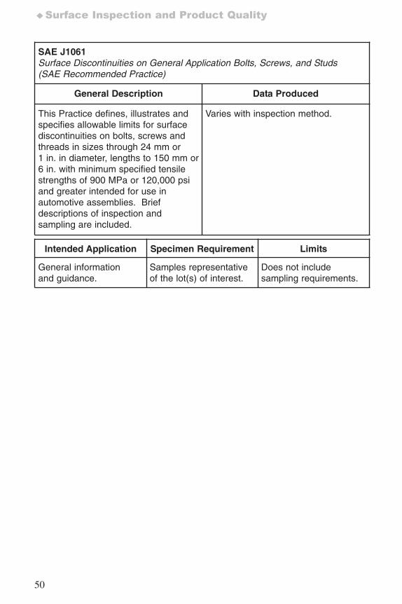
SAE J1061Surface Discontinuities on General Application Bolts, Screws, and Studs(SAE Recommended Practice)
General Description Data Produced
This Practice defines, illustrates andspecifies allowable limits for surfacediscontinuities on bolts, screws andthreads in sizes through 24 mm or1 in. in diameter, lengths to 150 mm or6 in. with minimum specified tensilestrengths of 900 MPa or 120,000 psiand greater intended for use inautomotive assemblies. Briefdescriptions of inspection andsampling are included.
Varies with inspection method.
Intended Application Specimen Requirement Limits
General informationand guidance.
Samples representativeof the lot(s) of interest.
Does not includesampling requirements.
7652_.qxd 9/27/2005 11:58 AM Page 50
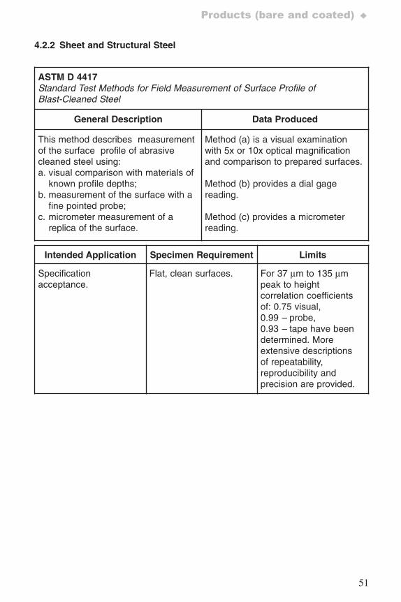
51
Products (bare and coated) ♦
4.2.2 Sheet and Structural Steel
ASTM D 4417Standard Test Methods for Field Measurement of Surface Profile ofBlast-Cleaned Steel
General Description Data Produced
This method describes measurementof the surface profile of abrasivecleaned steel using:a. visual comparison with materials of
known profile depths;b. measurement of the surface with a
fine pointed probe; c. micrometer measurement of a
replica of the surface.
Method (a) is a visual examinationwith 5x or 10x optical magnificationand comparison to prepared surfaces.
Method (b) provides a dial gagereading.
Method (c) provides a micrometerreading.
Intended Application Specimen Requirement Limits
Specificationacceptance.
Flat, clean surfaces. For 37 μm to 135 μmpeak to heightcorrelation coefficientsof: 0.75 visual,0.99 – probe,0.93 – tape have beendetermined. Moreextensive descriptionsof repeatability,reproducibility andprecision are provided.
7652_.qxd 9/27/2005 11:58 AM Page 51
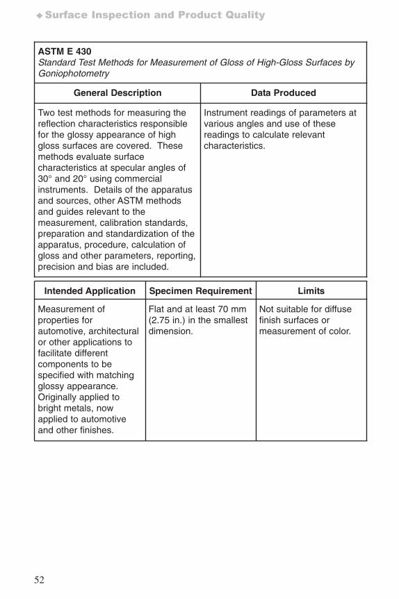
52
♦Surface Inspection and Product Quality
ASTM E 430 Standard Test Methods for Measurement of Gloss of High-Gloss Surfaces byGoniophotometry
General Description Data Produced
Two test methods for measuring thereflection characteristics responsiblefor the glossy appearance of highgloss surfaces are covered. Thesemethods evaluate surfacecharacteristics at specular angles of30° and 20° using commercialinstruments. Details of the apparatusand sources, other ASTM methodsand guides relevant to themeasurement, calibration standards,preparation and standardization of theapparatus, procedure, calculation ofgloss and other parameters, reporting,precision and bias are included.
Instrument readings of parameters atvarious angles and use of thesereadings to calculate relevantcharacteristics.
Intended Application Specimen Requirement Limits
Measurement ofproperties forautomotive, architecturalor other applications tofacilitate differentcomponents to bespecified with matchingglossy appearance.Originally applied tobright metals, nowapplied to automotiveand other finishes.
Flat and at least 70 mm(2.75 in.) in the smallestdimension.
Not suitable for diffusefinish surfaces ormeasurement of color.
7652_.qxd 9/27/2005 11:58 AM Page 52
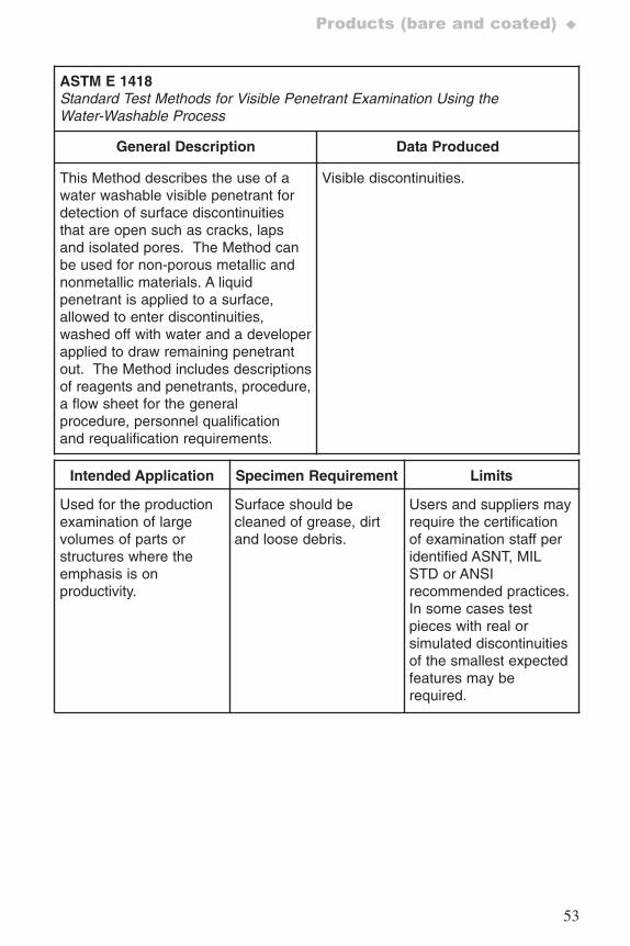
53
Products (bare and coated) ♦
ASTM E 1418 Standard Test Methods for Visible Penetrant Examination Using theWater-Washable Process
General Description Data Produced
This Method describes the use of awater washable visible penetrant fordetection of surface discontinuitiesthat are open such as cracks, lapsand isolated pores. The Method canbe used for non-porous metallic andnonmetallic materials. A liquidpenetrant is applied to a surface,allowed to enter discontinuities,washed off with water and a developerapplied to draw remaining penetrantout. The Method includes descriptionsof reagents and penetrants, procedure,a flow sheet for the generalprocedure, personnel qualificationand requalification requirements.
Visible discontinuities.
Intended Application Specimen Requirement Limits
Used for the productionexamination of largevolumes of parts orstructures where theemphasis is onproductivity.
Surface should becleaned of grease, dirtand loose debris.
Users and suppliers mayrequire the certificationof examination staff peridentified ASNT, MILSTD or ANSIrecommended practices.In some cases testpieces with real orsimulated discontinuitiesof the smallest expectedfeatures may berequired.
7652_.qxd 9/27/2005 11:58 AM Page 53
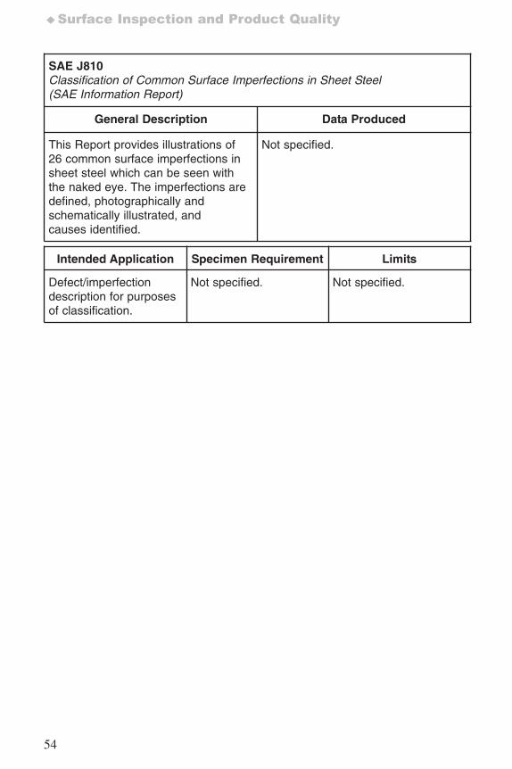
54
♦Surface Inspection and Product Quality
SAE J810Classification of Common Surface Imperfections in Sheet Steel (SAE Information Report)
General Description Data Produced
This Report provides illustrations of26 common surface imperfections insheet steel which can be seen withthe naked eye. The imperfections aredefined, photographically andschematically illustrated, andcauses identified.
Not specified.
Intended Application Specimen Requirement Limits
Defect/imperfectiondescription for purposesof classification.
Not specified. Not specified.
7652_.qxd 9/27/2005 11:58 AM Page 54
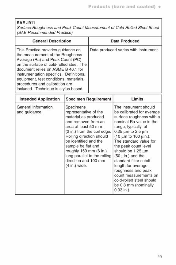
55
Products (bare and coated) ♦
SAE J911Surface Roughness and Peak Count Measurement of Cold Rolled Steel Sheet (SAE Recommended Practice)
General Description Data Produced
This Practice provides guidance onthe measurement of the RoughnessAverage (Ra) and Peak Count (PC)on the surface of cold-rolled steel. Thedocument relies on ASME B 46.1 forinstrumentation specifics. Definitions,equipment, test conditions, materials,procedures and calibration areincluded. Technique is stylus based.
Data produced varies with instrument.
Intended Application Specimen Requirement Limits
General informationand guidance.
Specimensrepresentative of thematerial as producedand removed from anarea at least 50 mm(2 in.) from the coil edge.Rolling direction shouldbe identified and thesample be flat androughly 150 mm (6 in.)long parallel to the rollingdirection and 100 mm(4 in.) wide.
The instrument shouldbe calibrated for averagesurface roughness with anominal Ra value in therange, typically, of0.25 μm to 2.5 μm(10 μm to 100 μin.).The standard value forthe peak count levelshould be 1.25 μm(50 μin.) and thestandard filter cutofflength for averageroughness and peakcount measurements oncold-rolled steel shouldbe 0.8 mm (nominally0.03 in.).
7652_.qxd 9/27/2005 11:58 AM Page 55
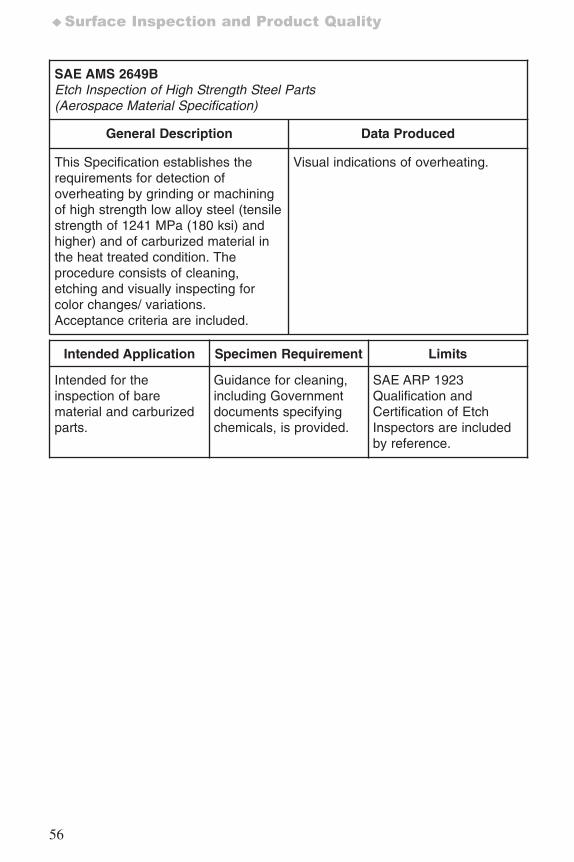
56
♦Surface Inspection and Product Quality
SAE AMS 2649B Etch Inspection of High Strength Steel Parts(Aerospace Material Specification)
General Description Data Produced
This Specification establishes therequirements for detection ofoverheating by grinding or machiningof high strength low alloy steel (tensilestrength of 1241 MPa (180 ksi) andhigher) and of carburized material inthe heat treated condition. Theprocedure consists of cleaning,etching and visually inspecting forcolor changes/ variations.Acceptance criteria are included.
Visual indications of overheating.
Intended Application Specimen Requirement Limits
Intended for theinspection of barematerial and carburizedparts.
Guidance for cleaning,including Governmentdocuments specifyingchemicals, is provided.
SAE ARP 1923Qualification andCertification of EtchInspectors are includedby reference.
7652_.qxd 9/27/2005 11:58 AM Page 56
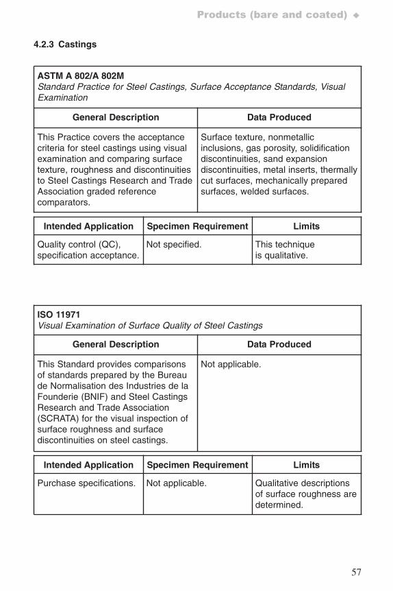
57
Products (bare and coated) ♦
4.2.3 Castings
ASTM A 802/A 802MStandard Practice for Steel Castings, Surface Acceptance Standards, VisualExamination
General Description Data Produced
This Practice covers the acceptancecriteria for steel castings using visualexamination and comparing surfacetexture, roughness and discontinuitiesto Steel Castings Research and TradeAssociation graded referencecomparators.
Surface texture, nonmetallicinclusions, gas porosity, solidificationdiscontinuities, sand expansiondiscontinuities, metal inserts, thermallycut surfaces, mechanically preparedsurfaces, welded surfaces.
Intended Application Specimen Requirement Limits
Quality control (QC),specification acceptance.
Not specified. This techniqueis qualitative.
ISO 11971Visual Examination of Surface Quality of Steel Castings
General Description Data Produced
This Standard provides comparisonsof standards prepared by the Bureaude Normalisation des Industries de laFounderie (BNIF) and Steel CastingsResearch and Trade Association(SCRATA) for the visual inspection ofsurface roughness and surfacediscontinuities on steel castings.
Not applicable.
Intended Application Specimen Requirement Limits
Purchase specifications. Not applicable. Qualitative descriptionsof surface roughness aredetermined.
7652_.qxd 9/27/2005 11:58 AM Page 57
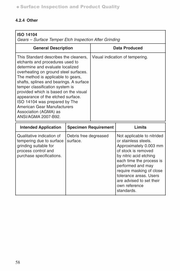
58
♦Surface Inspection and Product Quality
4.2.4 Other
ISO 14104Gears – Surface Temper Etch Inspection After Grinding
General Description Data Produced
This Standard describes the cleaners,etchants and procedures used todetermine and evaluate localizedoverheating on ground steel surfaces.The method is applicable to gears,shafts, splines and bearings. A surfacetemper classification system isprovided which is based on the visualappearance of the etched surface.ISO 14104 was prepared by TheAmerican Gear ManufacturersAssociation (AGMA) asANSI/AGMA 2007-B92.
Visual indication of tempering.
Intended Application Specimen Requirement Limits
Qualitative indication of tempering due to surfacegrinding suitable forprocess control andpurchase specifications.
Debris free degreasedsurface.
Not applicable to nitridedor stainless steels.Approximately 0.003 mmof stock is removedby nitric acid etchingeach time the process isperformed and mayrequire masking of closetolerance areas. Usersare advised to set theirown referencestandards.
7652_.qxd 9/27/2005 11:58 AM Page 58
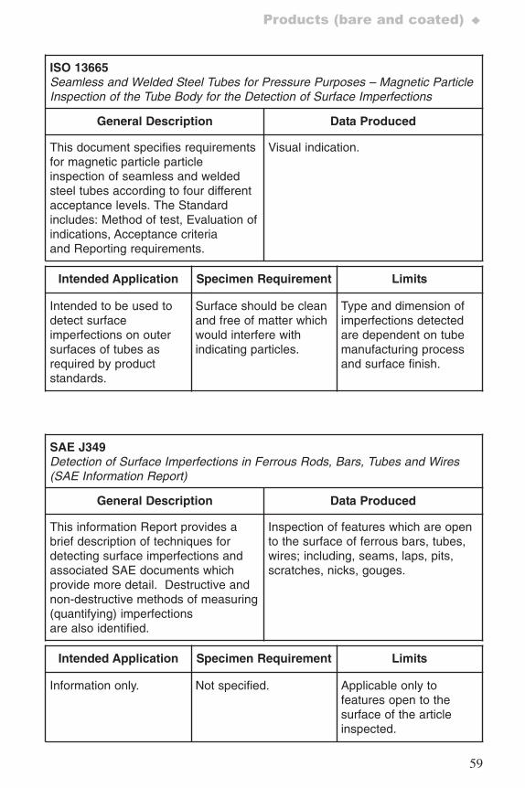
59
Products (bare and coated) ♦
ISO 13665Seamless and Welded Steel Tubes for Pressure Purposes – Magnetic ParticleInspection of the Tube Body for the Detection of Surface Imperfections
General Description Data Produced
This document specifies requirementsfor magnetic particle particleinspection of seamless and weldedsteel tubes according to four differentacceptance levels. The Standardincludes: Method of test, Evaluation ofindications, Acceptance criteriaand Reporting requirements.
Visual indication.
Intended Application Specimen Requirement Limits
Intended to be used todetect surfaceimperfections on outersurfaces of tubes asrequired by productstandards.
Surface should be cleanand free of matter whichwould interfere withindicating particles.
Type and dimension ofimperfections detectedare dependent on tubemanufacturing processand surface finish.
SAE J349Detection of Surface Imperfections in Ferrous Rods, Bars, Tubes and Wires (SAE Information Report)
General Description Data Produced
This information Report provides abrief description of techniques fordetecting surface imperfections andassociated SAE documents whichprovide more detail. Destructive andnon-destructive methods of measuring(quantifying) imperfectionsare also identified.
Inspection of features which are opento the surface of ferrous bars, tubes,wires; including, seams, laps, pits,scratches, nicks, gouges.
Intended Application Specimen Requirement Limits
Information only. Not specified. Applicable only tofeatures open to thesurface of the articleinspected.
7652_.qxd 9/27/2005 11:58 AM Page 59
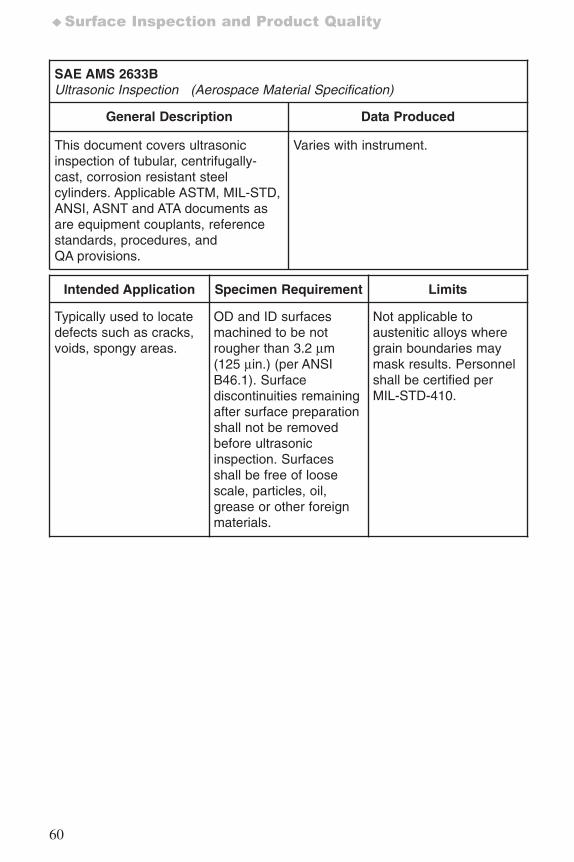
60
♦Surface Inspection and Product Quality
SAE AMS 2633BUltrasonic Inspection (Aerospace Material Specification)
General Description Data Produced
This document covers ultrasonicinspection of tubular, centrifugally-cast, corrosion resistant steelcylinders. Applicable ASTM, MIL-STD,ANSI, ASNT and ATA documents asare equipment couplants, referencestandards, procedures, andQA provisions.
Varies with instrument.
Intended Application Specimen Requirement Limits
Typically used to locatedefects such as cracks,voids, spongy areas.
OD and ID surfacesmachined to be notrougher than 3.2 μm(125 μin.) (per ANSIB46.1). Surfacediscontinuities remainingafter surface preparationshall not be removedbefore ultrasonicinspection. Surfacesshall be free of loosescale, particles, oil,grease or other foreignmaterials.
Not applicable toaustenitic alloys wheregrain boundaries maymask results. Personnelshall be certified perMIL-STD-410.
7652_.qxd 9/27/2005 11:58 AM Page 60
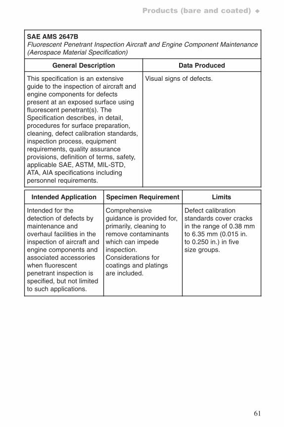
61
Products (bare and coated) ♦
SAE AMS 2647BFluorescent Penetrant Inspection Aircraft and Engine Component Maintenance(Aerospace Material Specification)
General Description Data Produced
This specification is an extensiveguide to the inspection of aircraft andengine components for defectspresent at an exposed surface usingfluorescent penetrant(s). TheSpecification describes, in detail,procedures for surface preparation,cleaning, defect calibration standards,inspection process, equipmentrequirements, quality assuranceprovisions, definition of terms, safety,applicable SAE, ASTM, MIL-STD,ATA, AIA specifications includingpersonnel requirements.
Visual signs of defects.
Intended Application Specimen Requirement Limits
Intended for thedetection of defects bymaintenance andoverhaul facilities in theinspection of aircraft andengine components andassociated accessorieswhen fluorescentpenetrant inspection isspecified, but not limitedto such applications.
Comprehensiveguidance is provided for,primarily, cleaning toremove contaminantswhich can impedeinspection.Considerations forcoatings and platingsare included.
Defect calibrationstandards cover cracksin the range of 0.38 mmto 6.35 mm (0.015 in.to 0.250 in.) in fivesize groups.
7652_.qxd 9/27/2005 11:58 AM Page 61
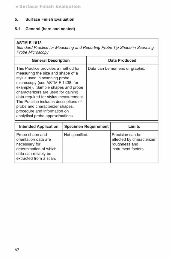
62
♦Surface Finish Evaluation
5. Surface Finish Evaluation
5.1 General (bare and coated)
ASTM E 1813Standard Practice for Measuring and Reporting Probe Tip Shape in ScanningProbe Microscopy
General Description Data Produced
This Practice provides a method formeasuring the size and shape of astylus used in scanning probemicroscopy (see ASTM F 1438, forexample). Sample shapes and probecharacterizers are used for gainingdata required for stylus measurement.The Practice includes descriptions ofprobe and characterizer shapes,procedure and information onanalytical probe approximations.
Data can be numeric or graphic.
Intended Application Specimen Requirement Limits
Probe shape andorientation data arenecessary fordetermination of whichdata can reliably beextracted from a scan.
Not specified. Precision can beaffected by characterizerroughness andinstrument factors.
7652_.qxd 9/27/2005 11:58 AM Page 62
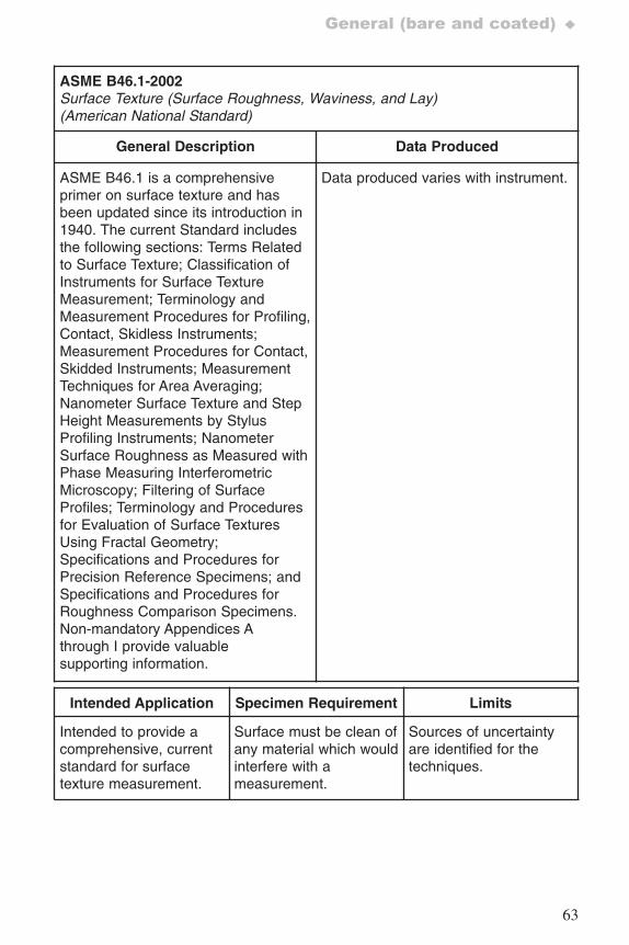
63
General (bare and coated) ♦
ASME B46.1-2002Surface Texture (Surface Roughness, Waviness, and Lay)(American National Standard)
General Description Data Produced
ASME B46.1 is a comprehensiveprimer on surface texture and hasbeen updated since its introduction in1940. The current Standard includesthe following sections: Terms Relatedto Surface Texture; Classification ofInstruments for Surface TextureMeasurement; Terminology andMeasurement Procedures for Profiling,Contact, Skidless Instruments;Measurement Procedures for Contact,Skidded Instruments; MeasurementTechniques for Area Averaging;Nanometer Surface Texture and StepHeight Measurements by StylusProfiling Instruments; NanometerSurface Roughness as Measured withPhase Measuring InterferometricMicroscopy; Filtering of SurfaceProfiles; Terminology and Proceduresfor Evaluation of Surface TexturesUsing Fractal Geometry;Specifications and Procedures forPrecision Reference Specimens; andSpecifications and Procedures forRoughness Comparison Specimens.Non-mandatory Appendices Athrough I provide valuablesupporting information.
Data produced varies with instrument.
Intended Application Specimen Requirement Limits
Intended to provide acomprehensive, currentstandard for surfacetexture measurement.
Surface must be clean ofany material which wouldinterfere with ameasurement.
Sources of uncertaintyare identified for thetechniques.
7652_.qxd 9/27/2005 11:58 AM Page 63
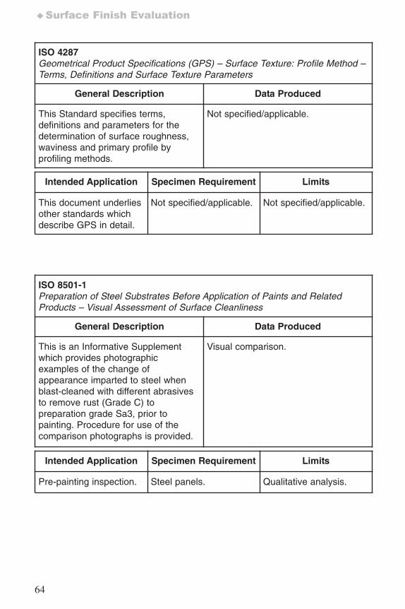
64
♦Surface Finish Evaluation
ISO 4287Geometrical Product Specifications (GPS) – Surface Texture: Profile Method –Terms, Definitions and Surface Texture Parameters
General Description Data Produced
This Standard specifies terms,definitions and parameters for thedetermination of surface roughness,waviness and primary profile byprofiling methods.
Not specified/applicable.
Intended Application Specimen Requirement Limits
This document underliesother standards whichdescribe GPS in detail.
Not specified/applicable. Not specified/applicable.
ISO 8501-1Preparation of Steel Substrates Before Application of Paints and RelatedProducts – Visual Assessment of Surface Cleanliness
General Description Data Produced
This is an Informative Supplementwhich provides photographicexamples of the change ofappearance imparted to steel whenblast-cleaned with different abrasivesto remove rust (Grade C) topreparation grade Sa3, prior topainting. Procedure for use of thecomparison photographs is provided.
Visual comparison.
Intended Application Specimen Requirement Limits
Pre-painting inspection. Steel panels. Qualitative analysis.
7652_.qxd 9/27/2005 11:58 AM Page 64
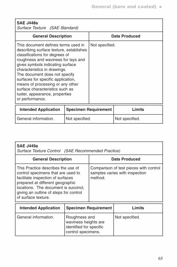
65
General (bare and coated) ♦
SAE J448aSurface Texture (SAE Standard)
General Description Data Produced
This document defines terms used indescribing surface texture, establishesclassifications for degrees ofroughness and waviness for lays andgives symbols indicating surfacecharacteristics in drawings. The document does not specifysurfaces for specific application,means of processing or any othersurface characteristics such asluster, appearance, propertiesor performance.
Not specified.
Intended Application Specimen Requirement Limits
General information. Not specified. Not specified.
SAE J449aSurface Texture Control (SAE Recommended Practice)
General Description Data Produced
This Practice describes the use ofcontrol specimens that are used tofacilitate inspection of surfacesprepared at different geographiclocations. The document is succinct,giving an outline of steps for controlof surface texture.
Comparison of test pieces with controlsamples varies with inspectionmethod.
Intended Application Specimen Requirement Limits
General information. Roughness andwaviness heights areidentified for specificcontrol specimens.
Not specified.
7652_.qxd 9/27/2005 11:58 AM Page 65
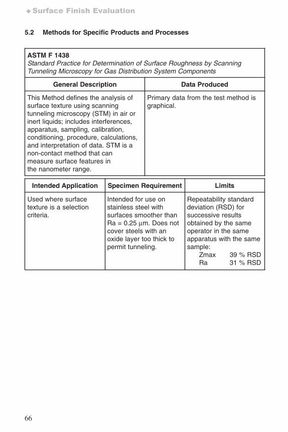
66
♦Surface Finish Evaluation
5.2 Methods for Specific Products and Processes
ASTM F 1438Standard Practice for Determination of Surface Roughness by ScanningTunneling Microscopy for Gas Distribution System Components
General Description Data Produced
This Method defines the analysis ofsurface texture using scanningtunneling microscopy (STM) in air orinert liquids; includes interferences,apparatus, sampling, calibration,conditioning, procedure, calculations,and interpretation of data. STM is anon-contact method that canmeasure surface features inthe nanometer range.
Primary data from the test method isgraphical.
Intended Application Specimen Requirement Limits
Used where surfacetexture is a selectioncriteria.
Intended for use onstainless steel withsurfaces smoother thanRa = 0.25 μm. Does notcover steels with anoxide layer too thick topermit tunneling.
Repeatability standarddeviation (RSD) forsuccessive resultsobtained by the sameoperator in the sameapparatus with the samesample:
Zmax 39 % RSDRa 31 % RSD
7652_.qxd 9/27/2005 11:58 AM Page 66
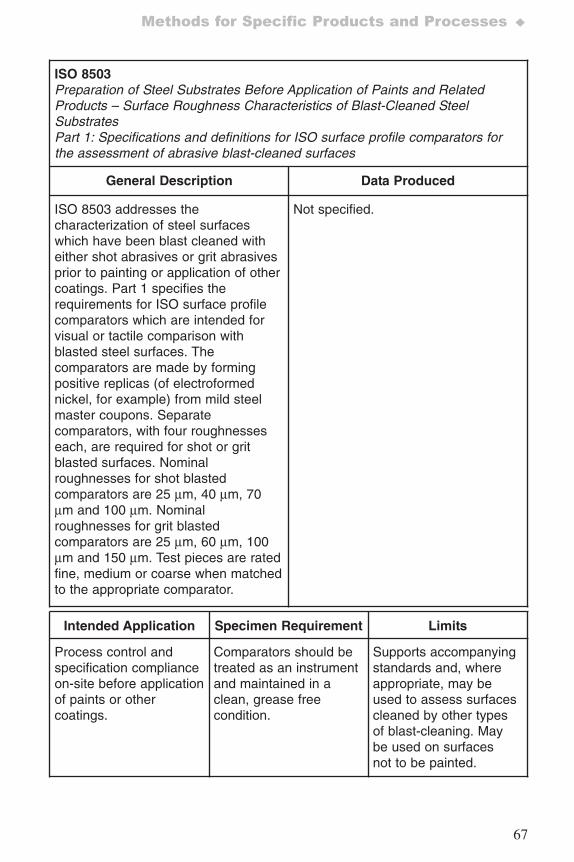
67
Methods for Specific Products and Processes ♦
ISO 8503Preparation of Steel Substrates Before Application of Paints and RelatedProducts – Surface Roughness Characteristics of Blast-Cleaned SteelSubstratesPart 1: Specifications and definitions for ISO surface profile comparators forthe assessment of abrasive blast-cleaned surfaces
General Description Data Produced
ISO 8503 addresses thecharacterization of steel surfaceswhich have been blast cleaned witheither shot abrasives or grit abrasivesprior to painting or application of othercoatings. Part 1 specifies therequirements for ISO surface profilecomparators which are intended forvisual or tactile comparison withblasted steel surfaces. Thecomparators are made by formingpositive replicas (of electroformednickel, for example) from mild steelmaster coupons. Separatecomparators, with four roughnesseseach, are required for shot or gritblasted surfaces. Nominalroughnesses for shot blastedcomparators are 25 μm, 40 μm, 70μm and 100 μm. Nominalroughnesses for grit blastedcomparators are 25 μm, 60 μm, 100μm and 150 μm. Test pieces are ratedfine, medium or coarse when matchedto the appropriate comparator.
Not specified.
Intended Application Specimen Requirement Limits
Process control andspecification complianceon-site before applicationof paints or othercoatings.
Comparators should betreated as an instrumentand maintained in aclean, grease freecondition.
Supports accompanyingstandards and, whereappropriate, may beused to assess surfacescleaned by other typesof blast-cleaning. Maybe used on surfacesnot to be painted.
7652_.qxd 9/27/2005 11:58 AM Page 67
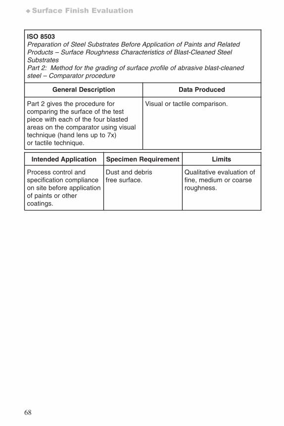
68
♦Surface Finish Evaluation
ISO 8503Preparation of Steel Substrates Before Application of Paints and RelatedProducts – Surface Roughness Characteristics of Blast-Cleaned SteelSubstratesPart 2: Method for the grading of surface profile of abrasive blast-cleanedsteel – Comparator procedure
General Description Data Produced
Part 2 gives the procedure forcomparing the surface of the testpiece with each of the four blastedareas on the comparator using visualtechnique (hand lens up to 7x)or tactile technique.
Visual or tactile comparison.
Intended Application Specimen Requirement Limits
Process control andspecification complianceon site before applicationof paints or othercoatings.
Dust and debrisfree surface.
Qualitative evaluation offine, medium or coarseroughness.
7652_.qxd 9/27/2005 11:58 AM Page 68
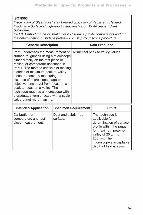
69
Methods for Specific Products and Processes ♦
ISO 8503Preparation of Steel Substrates Before Application of Paints and RelatedProducts – Surface Roughness Characteristics of Blast-Cleaned SteelSubstratesPart 3: Method for the calibration of ISO surface profile comparators and forthe determination of surface profile – Focusing microscope procedure
General Description Data Produced
Part 3 addresses the measurement ofsurface roughness using a microscopeeither directly on the test piece orreplica, or comparator described inPart 1. The method consists of makinga series of maximum peak-to-valleymeasurements by measuring thedistance of microscope stage orobjective lens travel from focus on apeak to focus on a valley. Thetechnique requires a microscope witha graduated vernier scale with a scalevalue of not more than 1 μm.
Numerical peak-to-valley values.
Intended Application Specimen Requirement Limits
Calibration ofcomparators and testpiece measurement.
Dust and debris freesurface.
The technique isapplicable fordetermination of surfaceprofile within the rangefor maximum peak-to-valley of 20 μm to200 μm. Themicroscope’s acceptabledepth of field is 2 μm.
7652_.qxd 9/27/2005 11:58 AM Page 69
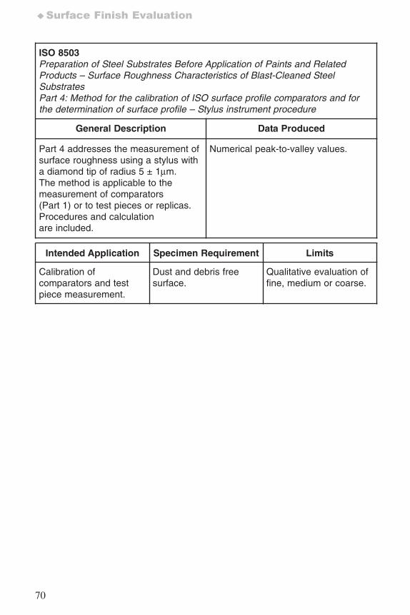
70
♦Surface Finish Evaluation
ISO 8503Preparation of Steel Substrates Before Application of Paints and RelatedProducts – Surface Roughness Characteristics of Blast-Cleaned SteelSubstratesPart 4: Method for the calibration of ISO surface profile comparators and forthe determination of surface profile – Stylus instrument procedure
General Description Data Produced
Part 4 addresses the measurement ofsurface roughness using a stylus witha diamond tip of radius 5 ± 1μm.The method is applicable to themeasurement of comparators(Part 1) or to test pieces or replicas.Procedures and calculationare included.
Numerical peak-to-valley values.
Intended Application Specimen Requirement Limits
Calibration ofcomparators and testpiece measurement.
Dust and debris freesurface.
Qualitative evaluation offine, medium or coarse.
7652_.qxd 9/27/2005 11:58 AM Page 70
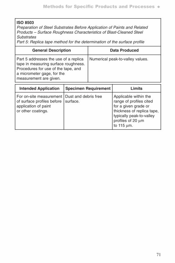
71
Methods for Specific Products and Processes ♦
ISO 8503Preparation of Steel Substrates Before Application of Paints and RelatedProducts – Surface Roughness Characteristics of Blast-Cleaned SteelSubstratesPart 5: Replica tape method for the determination of the surface profile
General Description Data Produced
Part 5 addresses the use of a replicatape in measuring surface roughness.Procedures for use of the tape, anda micrometer gage, for themeasurement are given.
Numerical peak-to-valley values.
Intended Application Specimen Requirement Limits
For on-site measurementof surface profiles beforeapplication of paintor other coatings.
Dust and debris freesurface.
Applicable within therange of profiles citedfor a given grade orthickness of replica tape,typically peak-to-valleyprofiles of 20 μmto 115 μm.
7652_.qxd 9/27/2005 11:58 AM Page 71
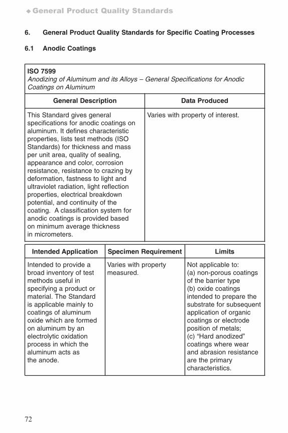
72
♦General Product Quality Standards
6. General Product Quality Standards for Specific Coating Processes
6.1 Anodic Coatings
ISO 7599Anodizing of Aluminum and its Alloys – General Specifications for AnodicCoatings on Aluminum
General Description Data Produced
This Standard gives generalspecifications for anodic coatings onaluminum. It defines characteristicproperties, lists test methods (ISOStandards) for thickness and massper unit area, quality of sealing,appearance and color, corrosionresistance, resistance to crazing bydeformation, fastness to light andultraviolet radiation, light reflectionproperties, electrical breakdownpotential, and continuity of thecoating. A classification system foranodic coatings is provided basedon minimum average thicknessin micrometers.
Varies with property of interest.
Intended Application Specimen Requirement Limits
Intended to provide abroad inventory of testmethods useful inspecifying a product ormaterial. The Standardis applicable mainly tocoatings of aluminumoxide which are formedon aluminum by anelectrolytic oxidationprocess in which thealuminum acts asthe anode.
Varies with propertymeasured.
Not applicable to: (a) non-porous coatingsof the barrier type(b) oxide coatingsintended to prepare thesubstrate for subsequentapplication of organiccoatings or electrodeposition of metals;(c) “Hard anodized”coatings where wearand abrasion resistanceare the primarycharacteristics.
7652_.qxd 9/27/2005 11:58 AM Page 72
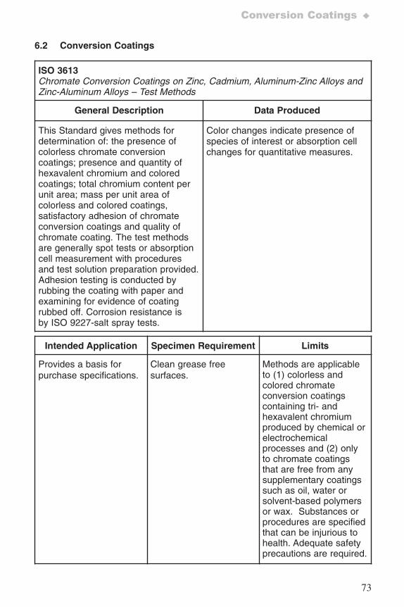
73
Conversion Coatings ♦
6.2 Conversion Coatings
ISO 3613Chromate Conversion Coatings on Zinc, Cadmium, Aluminum-Zinc Alloys andZinc-Aluminum Alloys – Test Methods
General Description Data Produced
This Standard gives methods fordetermination of: the presence ofcolorless chromate conversioncoatings; presence and quantity ofhexavalent chromium and coloredcoatings; total chromium content perunit area; mass per unit area ofcolorless and colored coatings,satisfactory adhesion of chromateconversion coatings and quality ofchromate coating. The test methodsare generally spot tests or absorptioncell measurement with proceduresand test solution preparation provided.Adhesion testing is conducted byrubbing the coating with paper andexamining for evidence of coatingrubbed off. Corrosion resistance isby ISO 9227-salt spray tests.
Color changes indicate presence ofspecies of interest or absorption cellchanges for quantitative measures.
Intended Application Specimen Requirement Limits
Provides a basis forpurchase specifications.
Clean grease freesurfaces.
Methods are applicableto (1) colorless andcolored chromateconversion coatingscontaining tri- andhexavalent chromiumproduced by chemical orelectrochemicalprocesses and (2) onlyto chromate coatingsthat are free from anysupplementary coatingssuch as oil, water orsolvent-based polymersor wax. Substances orprocedures are specifiedthat can be injurious tohealth. Adequate safetyprecautions are required.
7652_.qxd 9/27/2005 11:58 AM Page 73
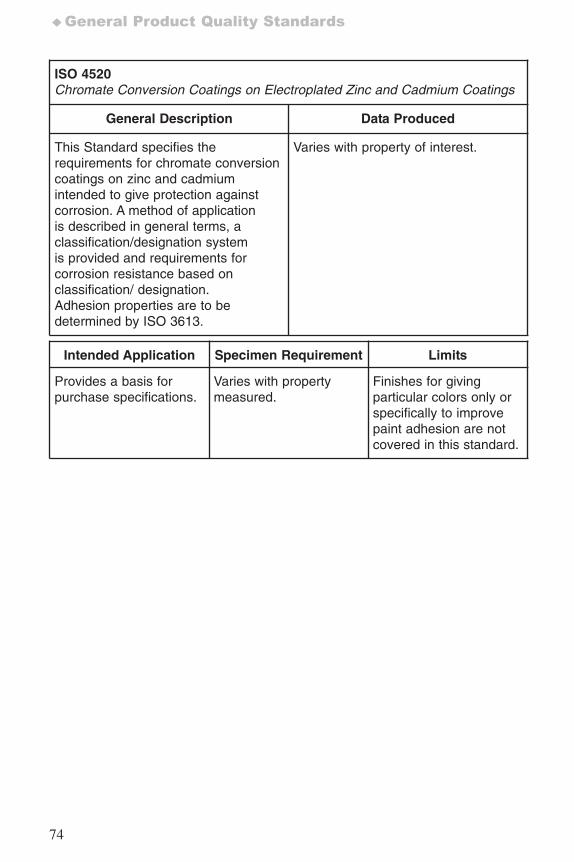
74
♦General Product Quality Standards
ISO 4520Chromate Conversion Coatings on Electroplated Zinc and Cadmium Coatings
General Description Data Produced
This Standard specifies therequirements for chromate conversioncoatings on zinc and cadmiumintended to give protection againstcorrosion. A method of applicationis described in general terms, aclassification/designation systemis provided and requirements forcorrosion resistance based onclassification/ designation.Adhesion properties are to bedetermined by ISO 3613.
Varies with property of interest.
Intended Application Specimen Requirement Limits
Provides a basis forpurchase specifications.
Varies with propertymeasured.
Finishes for givingparticular colors only orspecifically to improvepaint adhesion are notcovered in this standard.
7652_.qxd 9/27/2005 11:58 AM Page 74
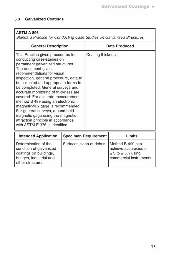
75
Galvanized Coatings ♦
6.3 Galvanized Coatings
ASTM A 896Standard Practice for Conducting Case Studies on Galvanized Structures
General Description Data Produced
This Practice gives procedures forconducting case-studies onpermanent galvanized structures.The document givesrecommendations for visualinspection, general procedure, data tobe collected and appropriate forms tobe completed. General surveys andaccurate monitoring of thickness arecovered. For accurate measurement,method B 499 using an electronicmagnetic-flux gage is recommended.For general surveys, a hand heldmagnetic gage using the magneticattraction principle in accordancewith ASTM E 376 is identified.
Coating thickness.
Intended Application Specimen Requirement Limits
Determination of thecondition of galvanizedcoatings on buildings,bridges, industrial andother structures.
Surfaces clean of debris. Method B 499 canachieve accuracies of ± 3 to ± 5% usingcommercial instruments.
7652_.qxd 9/27/2005 11:58 AM Page 75
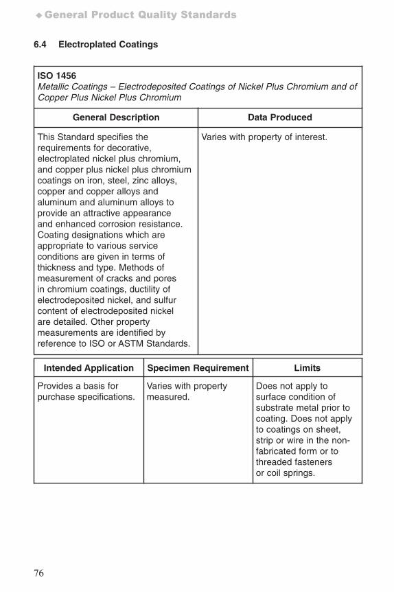
76
♦General Product Quality Standards
6.4 Electroplated Coatings
ISO 1456Metallic Coatings – Electrodeposited Coatings of Nickel Plus Chromium and ofCopper Plus Nickel Plus Chromium
General Description Data Produced
This Standard specifies therequirements for decorative,electroplated nickel plus chromium,and copper plus nickel plus chromiumcoatings on iron, steel, zinc alloys,copper and copper alloys andaluminum and aluminum alloys toprovide an attractive appearanceand enhanced corrosion resistance.Coating designations which areappropriate to various serviceconditions are given in terms ofthickness and type. Methods ofmeasurement of cracks and poresin chromium coatings, ductility ofelectrodeposited nickel, and sulfurcontent of electrodeposited nickelare detailed. Other propertymeasurements are identified byreference to ISO or ASTM Standards.
Varies with property of interest.
Intended Application Specimen Requirement Limits
Provides a basis forpurchase specifications.
Varies with propertymeasured.
Does not apply tosurface condition ofsubstrate metal prior tocoating. Does not applyto coatings on sheet,strip or wire in the non-fabricated form or tothreaded fastenersor coil springs.
7652_.qxd 9/27/2005 11:58 AM Page 76
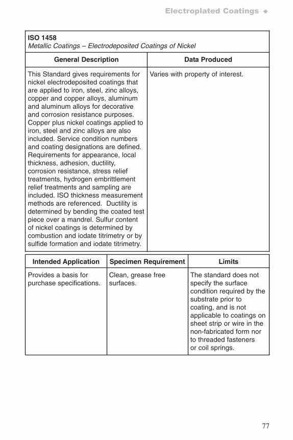
77
Electroplated Coatings ♦
ISO 1458Metallic Coatings – Electrodeposited Coatings of Nickel
General Description Data Produced
This Standard gives requirements fornickel electrodeposited coatings thatare applied to iron, steel, zinc alloys,copper and copper alloys, aluminumand aluminum alloys for decorativeand corrosion resistance purposes.Copper plus nickel coatings applied toiron, steel and zinc alloys are alsoincluded. Service condition numbersand coating designations are defined.Requirements for appearance, localthickness, adhesion, ductility,corrosion resistance, stress relieftreatments, hydrogen embrittlementrelief treatments and sampling areincluded. ISO thickness measurementmethods are referenced. Ductility isdetermined by bending the coated testpiece over a mandrel. Sulfur contentof nickel coatings is determined bycombustion and iodate titrimetry or bysulfide formation and iodate titrimetry.
Varies with property of interest.
Intended Application Specimen Requirement Limits
Provides a basis forpurchase specifications.
Clean, grease freesurfaces.
The standard does notspecify the surfacecondition required by thesubstrate prior tocoating, and is notapplicable to coatings onsheet strip or wire in thenon-fabricated form norto threaded fastenersor coil springs.
7652_.qxd 9/27/2005 11:58 AM Page 77
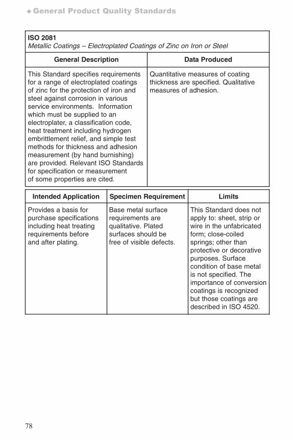
78
♦General Product Quality Standards
ISO 2081Metallic Coatings – Electroplated Coatings of Zinc on Iron or Steel
General Description Data Produced
This Standard specifies requirementsfor a range of electroplated coatingsof zinc for the protection of iron andsteel against corrosion in variousservice environments. Informationwhich must be supplied to anelectroplater, a classification code,heat treatment including hydrogenembrittlement relief, and simple testmethods for thickness and adhesionmeasurement (by hand burnishing)are provided. Relevant ISO Standardsfor specification or measurementof some properties are cited.
Quantitative measures of coatingthickness are specified. Qualitativemeasures of adhesion.
Intended Application Specimen Requirement Limits
Provides a basis forpurchase specificationsincluding heat treatingrequirements beforeand after plating.
Base metal surfacerequirements arequalitative. Platedsurfaces should befree of visible defects.
This Standard does notapply to: sheet, strip orwire in the unfabricatedform; close-coiledsprings; other thanprotective or decorativepurposes. Surfacecondition of base metalis not specified. Theimportance of conversioncoatings is recognizedbut those coatings aredescribed in ISO 4520.
7652_.qxd 9/27/2005 11:58 AM Page 78
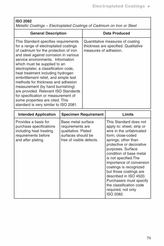
79
Electroplated Coatings ♦
ISO 2082Metallic Coatings – Electroplated Coatings of Cadmium on Iron or Steel
General Description Data Produced
This Standard specifies requirementsfor a range of electroplated coatingsof cadmium for the protection of ironand steel against corrosion in variousservice environments. Informationwhich must be supplied to anelectroplater, a classification code,heat treatment including hydrogenembrittlement relief, and simple testmethods for thickness and adhesionmeasurement (by hand burnishing)are provided. Relevant ISO Standardsfor specification or measurement ofsome properties are cited. Thisstandard is very similar to ISO 2081.
Quantitative measures of coatingthickness are specified. Qualitativemeasures of adhesion.
Intended Application Specimen Requirement Limits
Provides a basis forpurchase specificationsincluding heat treatingrequirements beforeand after plating.
Base metal surfacerequirements arequalitative. Platedsurfaces should befree of visible defects.
This Standard does notapply to: sheet, strip orwire in the unfabricatedform; close-coiledsprings; other thanprotective or decorativepurposes. Surfacecondition of base metalis not specified.Theimportance of conversioncoatings is recognizedbut those coatings aredescribed in ISO 4520.Purchasers must specifythe classification coderequired, not onlyISO 2082.
7652_.qxd 9/27/2005 11:58 AM Page 79
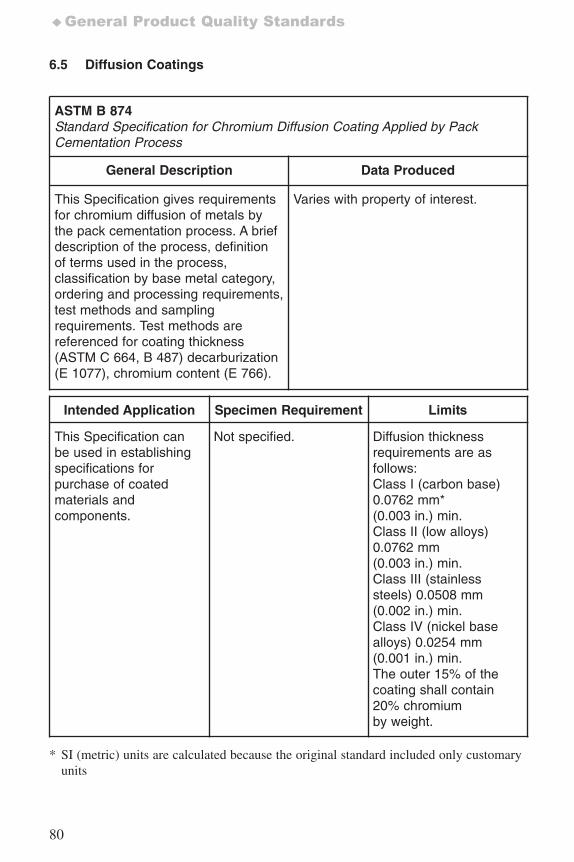
80
♦General Product Quality Standards
6.5 Diffusion Coatings
ASTM B 874Standard Specification for Chromium Diffusion Coating Applied by PackCementation Process
General Description Data Produced
This Specification gives requirementsfor chromium diffusion of metals bythe pack cementation process. A briefdescription of the process, definitionof terms used in the process,classification by base metal category,ordering and processing requirements,test methods and samplingrequirements. Test methods arereferenced for coating thickness(ASTM C 664, B 487) decarburization(E 1077), chromium content (E 766).
Varies with property of interest.
Intended Application Specimen Requirement Limits
This Specification canbe used in establishingspecifications forpurchase of coatedmaterials andcomponents.
Not specified. Diffusion thicknessrequirements are asfollows:Class I (carbon base)0.0762 mm*(0.003 in.) min.Class II (low alloys)0.0762 mm(0.003 in.) min.Class III (stainlesssteels) 0.0508 mm(0.002 in.) min.Class IV (nickel basealloys) 0.0254 mm(0.001 in.) min.The outer 15% of thecoating shall contain20% chromiumby weight.
* SI (metric) units are calculated because the original standard included only customaryunits
7652_.qxd 9/27/2005 11:58 AM Page 80
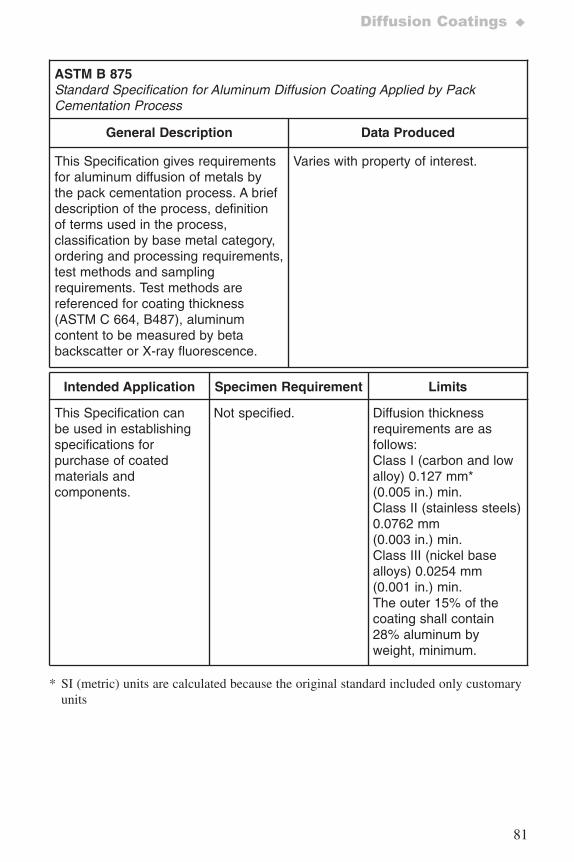
81
Diffusion Coatings ♦
ASTM B 875Standard Specification for Aluminum Diffusion Coating Applied by PackCementation Process
General Description Data Produced
This Specification gives requirementsfor aluminum diffusion of metals bythe pack cementation process. A briefdescription of the process, definitionof terms used in the process,classification by base metal category,ordering and processing requirements,test methods and samplingrequirements. Test methods arereferenced for coating thickness(ASTM C 664, B487), aluminumcontent to be measured by betabackscatter or X-ray fluorescence.
Varies with property of interest.
Intended Application Specimen Requirement Limits
This Specification canbe used in establishingspecifications forpurchase of coatedmaterials andcomponents.
Not specified. Diffusion thicknessrequirements are asfollows:Class I (carbon and lowalloy) 0.127 mm*(0.005 in.) min.Class II (stainless steels)0.0762 mm(0.003 in.) min.Class III (nickel basealloys) 0.0254 mm(0.001 in.) min.The outer 15% of thecoating shall contain28% aluminum byweight, minimum.
* SI (metric) units are calculated because the original standard included only customaryunits
7652_.qxd 9/27/2005 11:58 AM Page 81
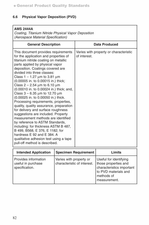
82
♦General Product Quality Standards
6.6 Physical Vapor Deposition (PVD)
AMS 2444ACoating, Titanium Nitride Physical Vapor Deposition(Aerospace Material Specification)
General Description Data Produced
This document provides requirementsfor the application and properties oftitanium nitride coating on metallicparts applied by physical vapordeposition. Coatings covered aredivided into three classes:Class 1 – 1.27 μm to 3.81 μm(0.00005 in. to 0.00015 in.) thick;Class 2 – 2.54 μm to 6.10 μm(0.00010 in. to 0.00024 in.) thick; and,Class 3 – 6.35 μm to 12.70 μm(0.00025 in. to 0.00050 in.) thick.Processing requirements, properties,quality, quality assurance, preparationfor delivery and surface roughnesssuggestions are included. Propertymeasurement methods are identifiedby reference to ASTM Standards,including: for thickness ASTM B 487,B 499, B568, E 376, E 1182; forhardness E 92 and E 384. Aqualitative adhesion test using a tapepull-off method is described.
Varies with property or characteristicof interest.
Intended Application Specimen Requirement Limits
Provides informationuseful in purchasespecification.
Varies with property orcharacteristic of interest.
Useful for identifyingthose properties andcharacteristics importantto PVD materials andmethods ofmeasurement.
7652_.qxd 9/27/2005 11:58 AM Page 82
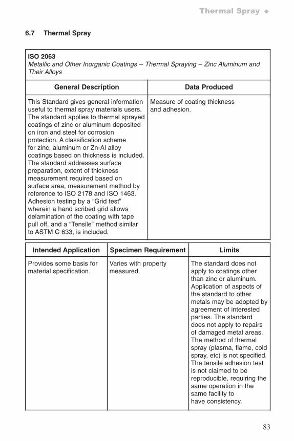
83
Thermal Spray ♦
6.7 Thermal Spray
ISO 2063Metallic and Other Inorganic Coatings – Thermal Spraying – Zinc Aluminum andTheir Alloys
General Description Data Produced
This Standard gives general informationuseful to thermal spray materials users.The standard applies to thermal sprayedcoatings of zinc or aluminum depositedon iron and steel for corrosionprotection. A classification schemefor zinc, aluminum or Zn-Al alloycoatings based on thickness is included.The standard addresses surfacepreparation, extent of thicknessmeasurement required based onsurface area, measurement method byreference to ISO 2178 and ISO 1463.Adhesion testing by a “Grid test”wherein a hand scribed grid allowsdelamination of the coating with tapepull off, and a “Tensile” method similarto ASTM C 633, is included.
Measure of coating thicknessand adhesion.
Intended Application Specimen Requirement Limits
Provides some basis formaterial specification.
Varies with propertymeasured.
The standard does notapply to coatings otherthan zinc or aluminum.Application of aspects ofthe standard to othermetals may be adopted byagreement of interestedparties. The standarddoes not apply to repairsof damaged metal areas.The method of thermalspray (plasma, flame, coldspray, etc) is not specified.The tensile adhesion testis not claimed to bereproducible, requiring thesame operation in thesame facility tohave consistency.
7652_.qxd 9/27/2005 11:58 AM Page 83
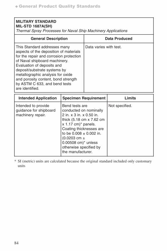
84
♦General Product Quality Standards
MILITARY STANDARDMIL-STD 1687A(SH) Thermal Spray Processes for Naval Ship Machinery Applications
General Description Data Produced
This Standard addresses manyaspects of the deposition of materialsfor the repair and corrosion protectionof Naval shipboard machinery.Evaluation of deposits anddeposit/substrate systems bymetallographic analysis for oxideand porosity content, bond strengthby ASTM C 633, and bend testsare identified.
Data varies with test.
Intended Application Specimen Requirement Limits
Intended to provideguidance for shipboardmachinery repair.
Bend tests areconducted on nominally2 in. x 3 in. x 0.50 in.thick (5.18 cm x 7.62 cmx 1.17 cm)* panels.Coating thicknesses areto be 0.008 ± 0.002 in.(0.0203 cm ±0.00508 cm)* unlessotherwise specified bythe manufacturer.
Not specified.
* SI (metric) units are calculated because the original standard included only customaryunits
7652_.qxd 9/27/2005 11:58 AM Page 84
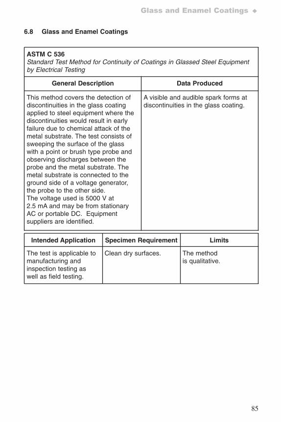
85
Glass and Enamel Coatings ♦
6.8 Glass and Enamel Coatings
ASTM C 536 Standard Test Method for Continuity of Coatings in Glassed Steel Equipmentby Electrical Testing
General Description Data Produced
This method covers the detection ofdiscontinuities in the glass coatingapplied to steel equipment where thediscontinuities would result in earlyfailure due to chemical attack of themetal substrate. The test consists ofsweeping the surface of the glasswith a point or brush type probe andobserving discharges between theprobe and the metal substrate. Themetal substrate is connected to theground side of a voltage generator,the probe to the other side.The voltage used is 5000 V at2.5 mA and may be from stationaryAC or portable DC. Equipmentsuppliers are identified.
A visible and audible spark forms atdiscontinuities in the glass coating.
Intended Application Specimen Requirement Limits
The test is applicable tomanufacturing andinspection testing aswell as field testing.
Clean dry surfaces. The methodis qualitative.
7652_.qxd 9/27/2005 11:58 AM Page 85
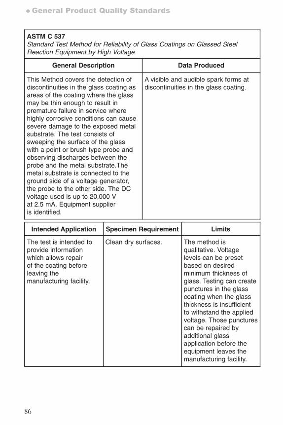
86
♦General Product Quality Standards
ASTM C 537 Standard Test Method for Reliability of Glass Coatings on Glassed SteelReaction Equipment by High Voltage
General Description Data Produced
This Method covers the detection ofdiscontinuities in the glass coating asareas of the coating where the glassmay be thin enough to result inpremature failure in service wherehighly corrosive conditions can causesevere damage to the exposed metalsubstrate. The test consists ofsweeping the surface of the glasswith a point or brush type probe andobserving discharges between theprobe and the metal substrate.Themetal substrate is connected to theground side of a voltage generator,the probe to the other side. The DCvoltage used is up to 20,000 Vat 2.5 mA. Equipment supplieris identified.
A visible and audible spark forms atdiscontinuities in the glass coating.
Intended Application Specimen Requirement Limits
The test is intended toprovide informationwhich allows repairof the coating beforeleaving themanufacturing facility.
Clean dry surfaces. The method isqualitative. Voltagelevels can be presetbased on desiredminimum thickness ofglass. Testing can createpunctures in the glasscoating when the glassthickness is insufficientto withstand the appliedvoltage. Those puncturescan be repaired byadditional glassapplication before theequipment leaves themanufacturing facility.
7652_.qxd 9/27/2005 11:58 AM Page 86
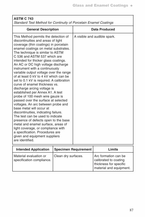
87
Glass and Enamel Coatings ♦
ASTM C 743 Standard Test Method for Continuity of Porcelain Enamel Coatings
General Description Data Produced
This Method permits the detection ofdiscontinuities and areas of lightcoverage (thin coatings) in porcelainenamel coatings on metal substrates.The technique is similar to ASTMC 536 and ASTM 537 which areintended for thicker glass coatings.An AC or DC high voltage dischargeinstrument with a continuouslyvariable output voltage over the rangeof at least 0 kV to 4 kV which can beset to 0.1 kV is required. A calibrationcurve of enamel thickness vs.discharge arcing voltage isestablished per Annex A1. A testprobe of 100 mesh wire gauze ispassed over the surface at selectedvoltages. An arc between probe andbase metal will occur atdiscontinuities, indicating failure.The test can be used to indicatepresence of defects open to the basemetal and enamel surface, areas oflight coverage, or compliance witha specification. Procedures aregiven and equipment suppliersare identified.
A visible and audible spark.
Intended Application Specimen Requirement Limits
Material evaluation orspecification compliance.
Clean dry surfaces. Arc formation can becalibrated to coatingthickness for specificmaterial and equipment.
7652_.qxd 9/27/2005 11:58 AM Page 87
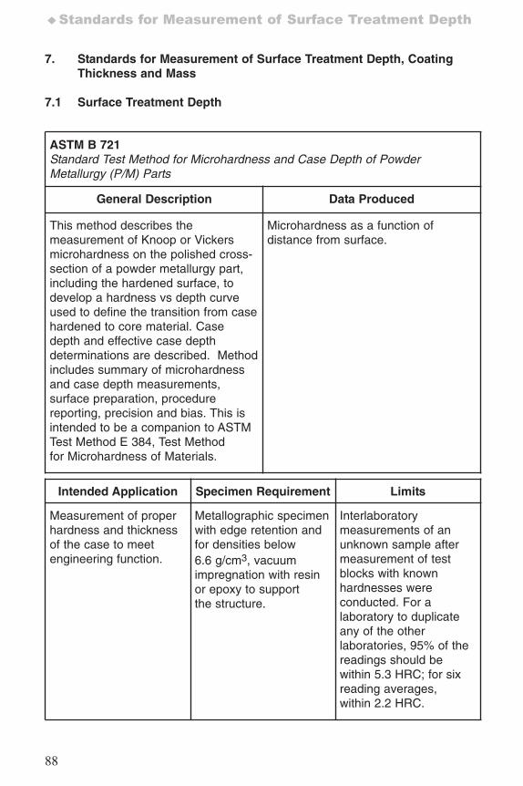
88
♦Standards for Measurement of Surface Treatment Depth
7. Standards for Measurement of Surface Treatment Depth, CoatingThickness and Mass
7.1 Surface Treatment Depth
ASTM B 721Standard Test Method for Microhardness and Case Depth of PowderMetallurgy (P/M) Parts
General Description Data Produced
This method describes themeasurement of Knoop or Vickersmicrohardness on the polished cross-section of a powder metallurgy part,including the hardened surface, todevelop a hardness vs depth curveused to define the transition from casehardened to core material. Casedepth and effective case depthdeterminations are described. Methodincludes summary of microhardnessand case depth measurements,surface preparation, procedurereporting, precision and bias. This isintended to be a companion to ASTMTest Method E 384, Test Methodfor Microhardness of Materials.
Microhardness as a function ofdistance from surface.
Intended Application Specimen Requirement Limits
Measurement of properhardness and thicknessof the case to meetengineering function.
Metallographic specimenwith edge retention andfor densities below6.6 g/cm3, vacuumimpregnation with resinor epoxy to supportthe structure.
Interlaboratorymeasurements of anunknown sample aftermeasurement of testblocks with knownhardnesses wereconducted. For alaboratory to duplicateany of the otherlaboratories, 95% of thereadings should bewithin 5.3 HRC; for sixreading averages,within 2.2 HRC.
7652_.qxd 9/27/2005 11:58 AM Page 88
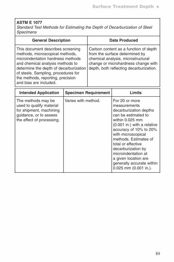
89
Surface Treatment Depth ♦
ASTM E 1077Standard Test Methods for Estimating the Depth of Decarburization of SteelSpecimens
General Description Data Produced
This document describes screeningmethods, microscopical methods,microindentation hardness methodsand chemical analysis methods todetermine the depth of decarburizationof steels. Sampling, procedures forthe methods, reporting, precisionand bias are included.
Carbon content as a function of depthfrom the surface determined bychemical analysis, microstructuralchange or microhardness change withdepth, both reflecting decarburization.
Intended Application Specimen Requirement Limits
The methods may beused to qualify materialfor shipment, machiningguidance, or to assessthe effect of processing.
Varies with method. For 20 or moremeasurementsdecarburization depthscan be estimated towithin 0.025 mm(0.001 in.) with a relativeaccuracy of 10% to 20%with microscopicalmethods. Estimates oftotal or effectivedecarburization bymicroindentation ata given location aregenerally accurate within0.025 mm (0.001 in.).
7652_.qxd 9/27/2005 11:58 AM Page 89
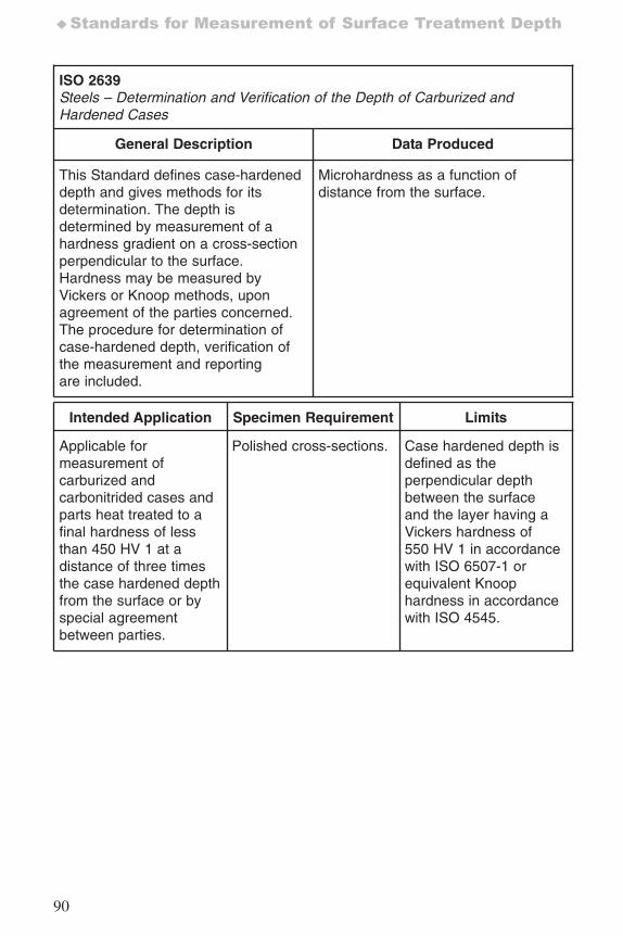
90
♦Standards for Measurement of Surface Treatment Depth
ISO 2639Steels – Determination and Verification of the Depth of Carburized andHardened Cases
General Description Data Produced
This Standard defines case-hardeneddepth and gives methods for itsdetermination. The depth isdetermined by measurement of ahardness gradient on a cross-sectionperpendicular to the surface.Hardness may be measured byVickers or Knoop methods, uponagreement of the parties concerned.The procedure for determination ofcase-hardened depth, verification ofthe measurement and reportingare included.
Microhardness as a function ofdistance from the surface.
Intended Application Specimen Requirement Limits
Applicable formeasurement ofcarburized andcarbonitrided cases andparts heat treated to afinal hardness of lessthan 450 HV 1 at adistance of three timesthe case hardened depthfrom the surface or byspecial agreementbetween parties.
Polished cross-sections. Case hardened depth isdefined as theperpendicular depthbetween the surfaceand the layer having aVickers hardness of550 HV 1 in accordancewith ISO 6507-1 orequivalent Knoophardness in accordancewith ISO 4545.
7652_.qxd 9/27/2005 11:58 AM Page 90
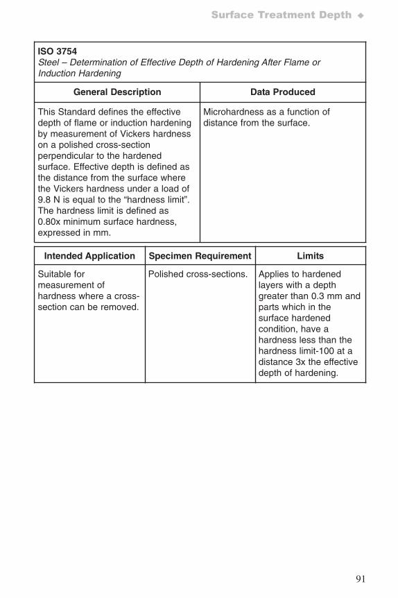
91
Surface Treatment Depth ♦
ISO 3754Steel – Determination of Effective Depth of Hardening After Flame orInduction Hardening
General Description Data Produced
This Standard defines the effectivedepth of flame or induction hardeningby measurement of Vickers hardnesson a polished cross-sectionperpendicular to the hardenedsurface. Effective depth is defined asthe distance from the surface wherethe Vickers hardness under a load of9.8 N is equal to the “hardness limit”.The hardness limit is defined as0.80x minimum surface hardness,expressed in mm.
Microhardness as a function ofdistance from the surface.
Intended Application Specimen Requirement Limits
Suitable formeasurement ofhardness where a cross-section can be removed.
Polished cross-sections. Applies to hardenedlayers with a depthgreater than 0.3 mm andparts which in thesurface hardenedcondition, have ahardness less than thehardness limit-100 at adistance 3x the effectivedepth of hardening.
7652_.qxd 9/27/2005 11:58 AM Page 91
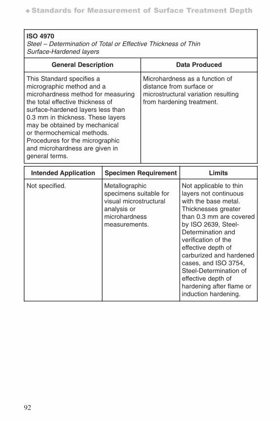
92
♦Standards for Measurement of Surface Treatment Depth
ISO 4970Steel – Determination of Total or Effective Thickness of ThinSurface-Hardened layers
General Description Data Produced
This Standard specifies amicrographic method and amicrohardness method for measuringthe total effective thickness ofsurface-hardened layers less than0.3 mm in thickness. These layersmay be obtained by mechanicalor thermochemical methods.Procedures for the micrographicand microhardness are given ingeneral terms.
Microhardness as a function ofdistance from surface ormicrostructural variation resultingfrom hardening treatment.
Intended Application Specimen Requirement Limits
Not specified. Metallographicspecimens suitable forvisual microstructuralanalysis ormicrohardnessmeasurements.
Not applicable to thinlayers not continuouswith the base metal.Thicknesses greaterthan 0.3 mm are coveredby ISO 2639, Steel-Determination andverification of theeffective depth ofcarburized and hardenedcases, and ISO 3754,Steel-Determination ofeffective depth ofhardening after flame orinduction hardening.
7652_.qxd 9/27/2005 11:58 AM Page 92
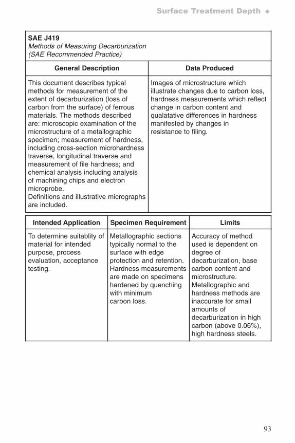
93
Surface Treatment Depth ♦
SAE J419Methods of Measuring Decarburization (SAE Recommended Practice)
General Description Data Produced
This document describes typicalmethods for measurement of theextent of decarburization (loss ofcarbon from the surface) of ferrousmaterials. The methods describedare: microscopic examination of themicrostructure of a metallographicspecimen; measurement of hardness,including cross-section microhardnesstraverse, longitudinal traverse andmeasurement of file hardness; andchemical analysis including analysisof machining chips and electronmicroprobe.Definitions and illustrative micrographsare included.
Images of microstructure whichillustrate changes due to carbon loss,hardness measurements which reflectchange in carbon content andqualatative differences in hardnessmanifested by changes inresistance to filing.
Intended Application Specimen Requirement Limits
To determine suitablity ofmaterial for intendedpurpose, processevaluation, acceptancetesting.
Metallographic sectionstypically normal to thesurface with edgeprotection and retention.Hardness measurementsare made on specimenshardened by quenchingwith minimumcarbon loss.
Accuracy of methodused is dependent ondegree ofdecarburization, basecarbon content andmicrostructure.Metallographic andhardness methods areinaccurate for smallamounts ofdecarburization in highcarbon (above 0.06%),high hardness steels.
7652_.qxd 9/27/2005 11:58 AM Page 93
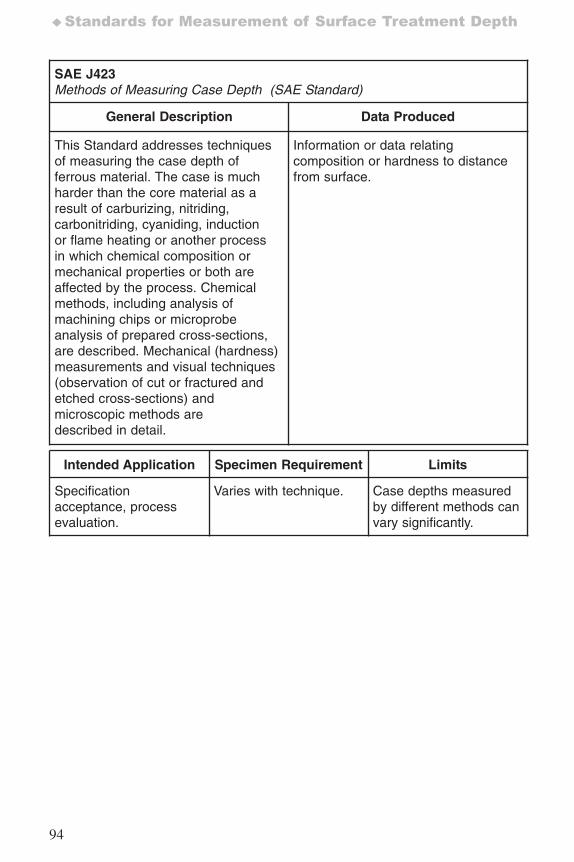
94
♦Standards for Measurement of Surface Treatment Depth
SAE J423Methods of Measuring Case Depth (SAE Standard)
General Description Data Produced
This Standard addresses techniquesof measuring the case depth offerrous material. The case is muchharder than the core material as aresult of carburizing, nitriding,carbonitriding, cyaniding, inductionor flame heating or another processin which chemical composition ormechanical properties or both areaffected by the process. Chemicalmethods, including analysis ofmachining chips or microprobeanalysis of prepared cross-sections,are described. Mechanical (hardness)measurements and visual techniques(observation of cut or fractured andetched cross-sections) andmicroscopic methods aredescribed in detail.
Information or data relatingcomposition or hardness to distancefrom surface.
Intended Application Specimen Requirement Limits
Specificationacceptance, processevaluation.
Varies with technique. Case depths measuredby different methods canvary significantly.
7652_.qxd 9/27/2005 11:58 AM Page 94
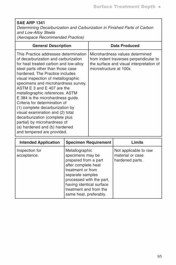
95
Surface Treatment Depth ♦
SAE ARP 1341Determining Decarburization and Carburization in Finished Parts of Carbonand Low-Alloy Steels(Aerospace Recommended Practice)
General Description Data Produced
This Practice addresses determinationof decarburization and carburizationfor heat treated carbon and low-alloysteel parts other than those casehardened. The Practice includesvisual inspection of metallographicspecimens and microhardness survey.ASTM E 3 and E 407 are themetallographic references. ASTME 384 is the microhardness guide.Criteria for determination of(1) complete decarburization byvisual examination and (2) totaldecarburization (complete pluspartial) by microhardness of(a) hardened and (b) hardenedand tempered are provided.
Microhardness values determinedfrom indent traverses perpendicular tothe surface and visual interpretation ofmicrostructure at 100x.
Intended Application Specimen Requirement Limits
Inspection foracceptance.
Metallographicspecimens may beprepared from a partafter complete heattreatment or fromseparate samplesprocessed with the part,having identical surfacetreatment and from thesame heat, preferably.
Not applicable to rawmaterial or casehardened parts.
7652_.qxd 9/27/2005 11:58 AM Page 95
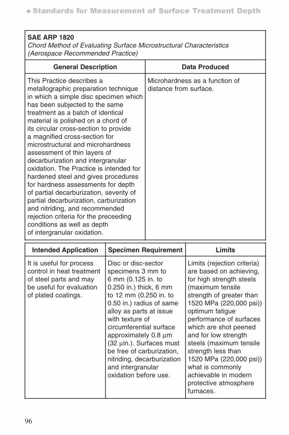
96
♦Standards for Measurement of Surface Treatment Depth
SAE ARP 1820Chord Method of Evaluating Surface Microstructural Characteristics(Aerospace Recommended Practice)
General Description Data Produced
This Practice describes ametallographic preparation techniquein which a simple disc specimen whichhas been subjected to the sametreatment as a batch of identicalmaterial is polished on a chord ofits circular cross-section to providea magnified cross-section formicrostructural and microhardnessassessment of thin layers ofdecarburization and intergranularoxidation. The Practice is intended forhardened steel and gives proceduresfor hardness assessments for depthof partial decarburization, severity ofpartial decarburization, carburizationand nitriding, and recommendedrejection criteria for the preceedingconditions as well as depthof intergranular oxidation.
Microhardness as a function ofdistance from surface.
Intended Application Specimen Requirement Limits
It is useful for processcontrol in heat treatmentof steel parts and maybe useful for evaluationof plated coatings.
Disc or disc-sectorspecimens 3 mm to6 mm (0.125 in. to0.250 in.) thick, 6 mmto 12 mm (0.250 in. to0.50 in.) radius of samealloy as parts at issuewith texture ofcircumferential surfaceapproximately 0.8 μm(32 μin.). Surfaces mustbe free of carburization,nitriding, decarburizationand intergranularoxidation before use.
Limits (rejection criteria)are based on achieving,for high strength steels(maximum tensilestrength of greater than1520 MPa (220,000 psi))optimum fatigueperformance of surfaceswhich are shot peenedand for low strengthsteels (maximum tensilestrength less than1520 MPa (220,000 psi))what is commonlyachievable in modernprotective atmospherefurnaces.
7652_.qxd 9/27/2005 11:58 AM Page 96
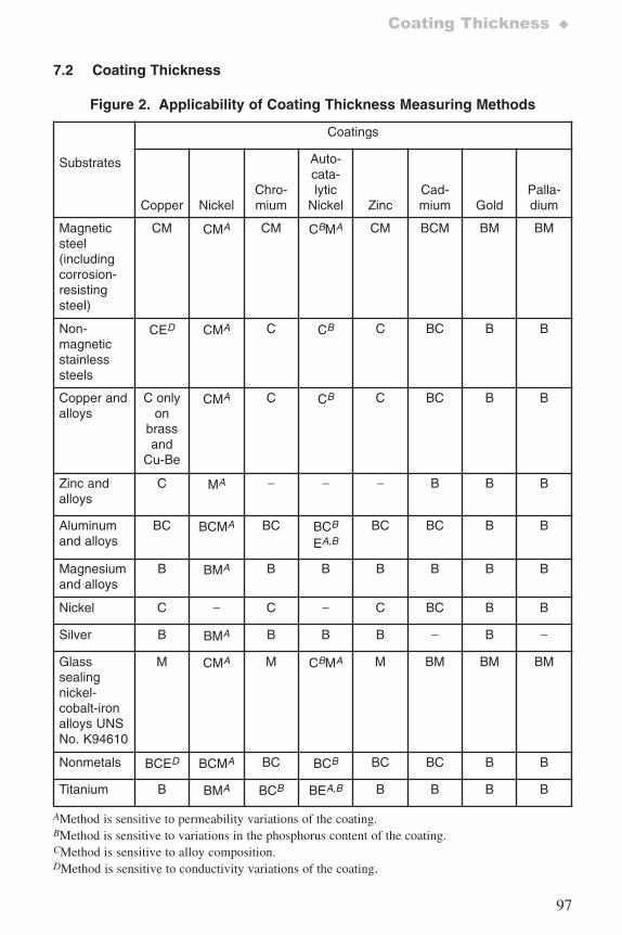
97
Coating Thickness ♦
7.2 Coating Thickness
Figure 2. Applicability of Coating Thickness Measuring Methods
Substrates
Coatings
Copper NickelChro-mium
Auto-cata-lytic
Nickel ZincCad-mium Gold
Palla-dium
Magneticsteel(includingcorrosion-resistingsteel)
CM CMA CM CBMA CM BCM BM BM
Non-magneticstainlesssteels
CED CMA C CB C BC B B
Copper andalloys
C onlyon
brassand
Cu-Be
CMA C CB C BC B B
Zinc andalloys
C MA − − − B B B
Aluminumand alloys
BC BCMA BC BCB
EA,BBC BC B B
Magnesium and alloys
B BMA B B B B B B
Nickel C − C − C BC B B
Silver B BMA B B B − B −
Glasssealingnickel-cobalt-ironalloys UNSNo. K94610
M CMA M CBMA M BM BM BM
Nonmetals BCED BCMA BC BCB BC BC B B
Titanium B BMA BCB BEA,B B B B B
AMethod is sensitive to permeability variations of the coating.BMethod is sensitive to variations in the phosphorus content of the coating.CMethod is sensitive to alloy composition.DMethod is sensitive to conductivity variations of the coating.
7652_.qxd 9/27/2005 11:58 AM Page 97
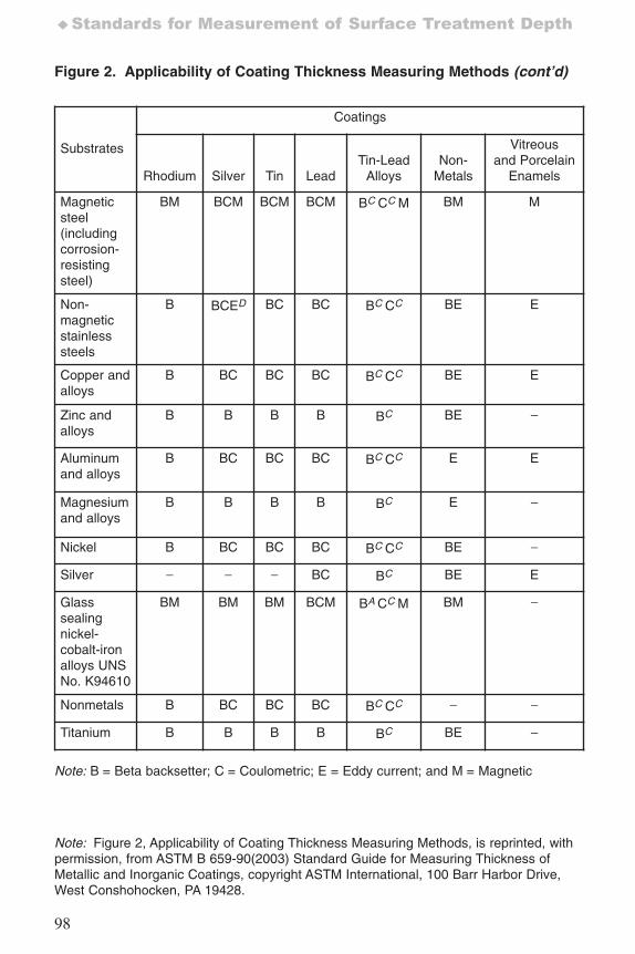
98
♦Standards for Measurement of Surface Treatment Depth
Figure 2. Applicability of Coating Thickness Measuring Methods (cont’d)
Substrates
Coatings
Rhodium Silver Tin LeadTin-Lead
AlloysNon-
Metals
Vitreousand Porcelain
Enamels
Magneticsteel(includingcorrosion-resistingsteel)
BM BCM BCM BCM BC CC M BM M
Non-magneticstainlesssteels
B BCED BC BC BC CC BE E
Copper andalloys
B BC BC BC BC CC BE E
Zinc andalloys
B B B B BC BE −
Aluminumand alloys
B BC BC BC BC CC E E
Magnesium and alloys
B B B B BC E −
Nickel B BC BC BC BC CC BE −
Silver − − − BC BC BE E
Glasssealingnickel-cobalt-ironalloys UNSNo. K94610
BM BM BM BCM BA CC M BM −
Nonmetals B BC BC BC BC CC − −
Titanium B B B B BC BE −
Note: Figure 2, Applicability of Coating Thickness Measuring Methods, is reprinted, withpermission, from ASTM B 659-90(2003) Standard Guide for Measuring Thickness ofMetallic and Inorganic Coatings, copyright ASTM International, 100 Barr Harbor Drive,West Conshohocken, PA 19428.
Note: B = Beta backsetter; C = Coulometric; E = Eddy current; and M = Magnetic
7652_.qxd 9/27/2005 11:58 AM Page 98
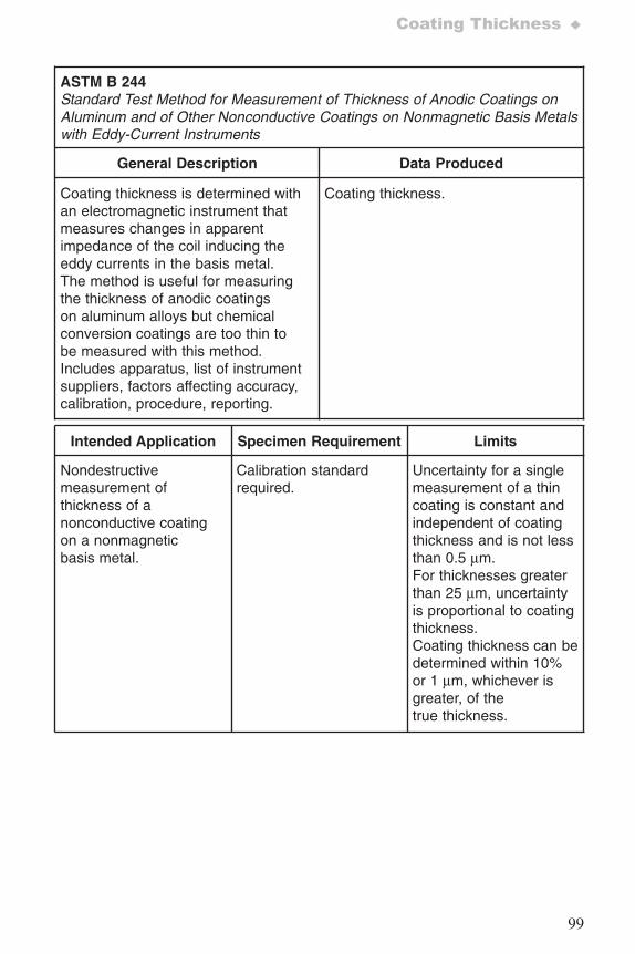
99
Coating Thickness ♦
ASTM B 244Standard Test Method for Measurement of Thickness of Anodic Coatings onAluminum and of Other Nonconductive Coatings on Nonmagnetic Basis Metalswith Eddy-Current Instruments
General Description Data Produced
Coating thickness is determined withan electromagnetic instrument thatmeasures changes in apparentimpedance of the coil inducing theeddy currents in the basis metal.The method is useful for measuringthe thickness of anodic coatingson aluminum alloys but chemicalconversion coatings are too thin tobe measured with this method.Includes apparatus, list of instrumentsuppliers, factors affecting accuracy,calibration, procedure, reporting.
Coating thickness.
Intended Application Specimen Requirement Limits
Nondestructivemeasurement ofthickness of anonconductive coatingon a nonmagneticbasis metal.
Calibration standardrequired.
Uncertainty for a singlemeasurement of a thincoating is constant andindependent of coatingthickness and is not lessthan 0.5 μm.For thicknesses greaterthan 25 μm, uncertaintyis proportional to coatingthickness.Coating thickness can bedetermined within 10%or 1 μm, whichever isgreater, of thetrue thickness.
7652_.qxd 9/27/2005 11:58 AM Page 99
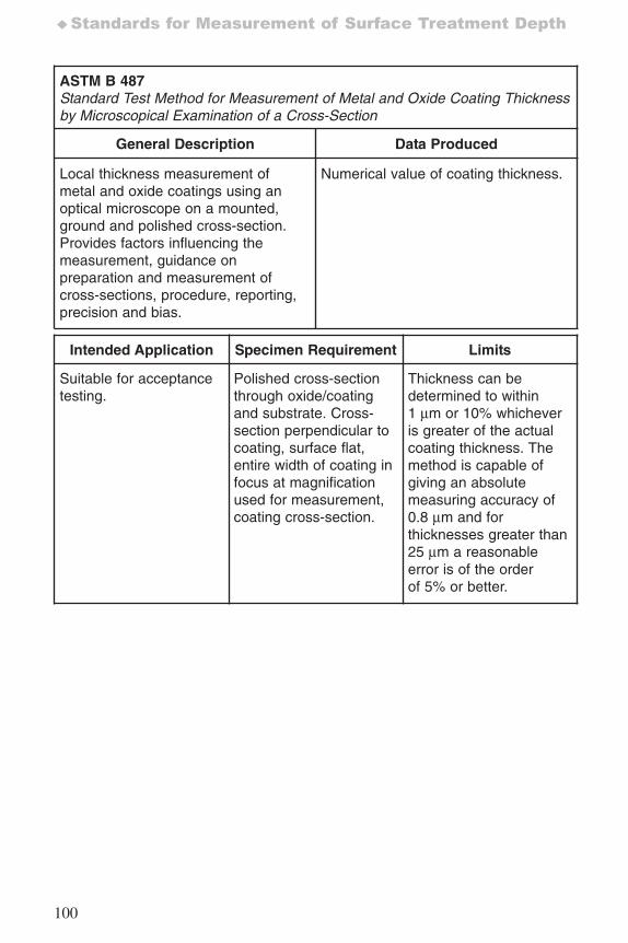
100
♦Standards for Measurement of Surface Treatment Depth
ASTM B 487Standard Test Method for Measurement of Metal and Oxide Coating Thicknessby Microscopical Examination of a Cross-Section
General Description Data Produced
Local thickness measurement ofmetal and oxide coatings using anoptical microscope on a mounted,ground and polished cross-section.Provides factors influencing themeasurement, guidance onpreparation and measurement ofcross-sections, procedure, reporting,precision and bias.
Numerical value of coating thickness.
Intended Application Specimen Requirement Limits
Suitable for acceptancetesting.
Polished cross-sectionthrough oxide/coatingand substrate. Cross-section perpendicular tocoating, surface flat,entire width of coating infocus at magnificationused for measurement,coating cross-section.
Thickness can bedetermined to within1 μm or 10% whicheveris greater of the actualcoating thickness. Themethod is capable ofgiving an absolutemeasuring accuracy of0.8 μm and forthicknesses greater than25 μm a reasonableerror is of the orderof 5% or better.
7652_.qxd 9/27/2005 11:58 AM Page 100
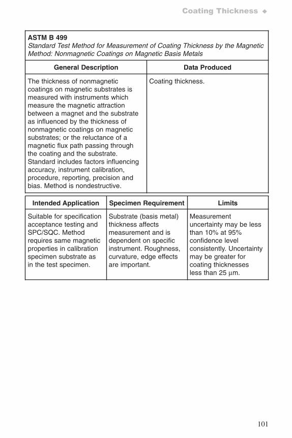
101
Coating Thickness ♦
ASTM B 499Standard Test Method for Measurement of Coating Thickness by the MagneticMethod: Nonmagnetic Coatings on Magnetic Basis Metals
General Description Data Produced
The thickness of nonmagneticcoatings on magnetic substrates ismeasured with instruments whichmeasure the magnetic attractionbetween a magnet and the substrateas influenced by the thickness ofnonmagnetic coatings on magneticsubstrates; or the reluctance of amagnetic flux path passing throughthe coating and the substrate.Standard includes factors influencingaccuracy, instrument calibration,procedure, reporting, precision andbias. Method is nondestructive.
Coating thickness.
Intended Application Specimen Requirement Limits
Suitable for specificationacceptance testing andSPC/SQC. Methodrequires same magneticproperties in calibrationspecimen substrate asin the test specimen.
Substrate (basis metal)thickness affectsmeasurement and isdependent on specificinstrument. Roughness,curvature, edge effectsare important.
Measurementuncertainty may be lessthan 10% at 95%confidence levelconsistently. Uncertaintymay be greater forcoating thicknessesless than 25 μm.
7652_.qxd 9/27/2005 11:58 AM Page 101

102
♦Standards for Measurement of Surface Treatment Depth
ASTM B 504Standard Test Method for Measurement of Thickness of Metallic Coatings bythe Coulometric Method
General Description Data Produced
The thickness of metallic coatings isdetermined by electrochemicallystripping an approximately 0.1 cm2
test area and either calculating theamount of material removed based onthe amount of electricity used or bycalibration against standards withknown coating thicknesses. Standardincludes factors affecting accuracy,calibration of instrument, procedure,precision and bias, electrolytes, andmeasurable coating/substratecombinations suitable for this method.
Coating mass interpreted as coatingthickness.
Intended Application Specimen Requirement Limits
Useful where a smallspot of coating canbe destroyed.
This localized test maynot measure variations incoating or alloyingbetween coatingand substrate.
Uncertainty of less than10% may be achieved.The uncertainty may begreater for thicknessesless than 1 μm orgreater than 50 μm.
7652_.qxd 9/27/2005 11:58 AM Page 102
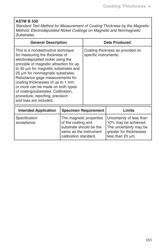
103
Coating Thickness ♦
ASTM B 530Standard Test Method for Measurement of Coating Thickness by the MagneticMethod: Electrodeposited Nickel Coatings on Magnetic and NonmagneticSubstrates
General Description Data Produced
This is a nondestructive techniquefor measuring the thickness ofelectrodeposited nickel using theprinciple of magnetic attraction for upto 50 μm for magnetic substrates and25 μm for nonmagnetic substrates.Reluctance gage measurements forcoating thicknesses of up to 1 mmor more can be made on both typesof coating/substrates. Calibration,procedure, reporting, precisionand bias are included.
Coating thickness as provided onspecific instruments.
Intended Application Specimen Requirement Limits
Specificationacceptance.
The magnetic propertiesof the coating andsubstrate should be thesame as the instrumentcalibration standard.
Uncertainty of less than10% may be achieved.The uncertainty may begreater for thicknessesless than 25 μm.
7652_.qxd 9/27/2005 11:58 AM Page 103
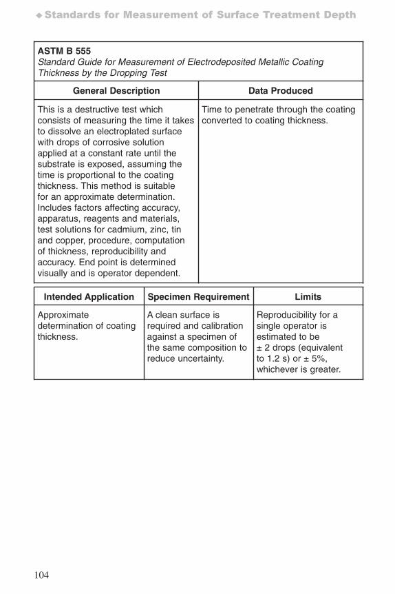
104
♦Standards for Measurement of Surface Treatment Depth
ASTM B 555Standard Guide for Measurement of Electrodeposited Metallic CoatingThickness by the Dropping Test
General Description Data Produced
This is a destructive test whichconsists of measuring the time it takesto dissolve an electroplated surfacewith drops of corrosive solutionapplied at a constant rate until thesubstrate is exposed, assuming thetime is proportional to the coatingthickness. This method is suitablefor an approximate determination.Includes factors affecting accuracy,apparatus, reagents and materials,test solutions for cadmium, zinc, tinand copper, procedure, computationof thickness, reproducibility andaccuracy. End point is determinedvisually and is operator dependent.
Time to penetrate through the coatingconverted to coating thickness.
Intended Application Specimen Requirement Limits
Approximatedetermination of coatingthickness.
A clean surface isrequired and calibrationagainst a specimen ofthe same composition toreduce uncertainty.
Reproducibility for asingle operator isestimated to be± 2 drops (equivalentto 1.2 s) or ± 5%,whichever is greater.
7652_.qxd 9/27/2005 11:58 AM Page 104
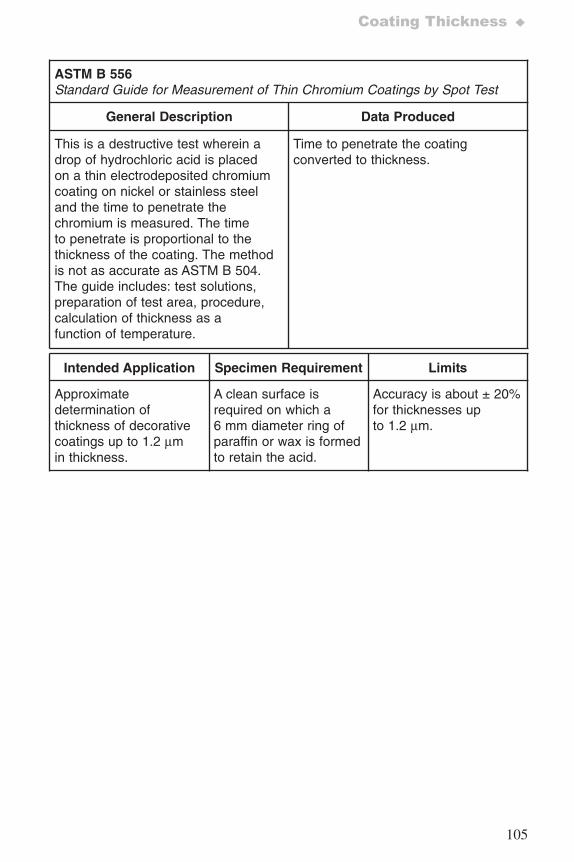
105
Coating Thickness ♦
ASTM B 556 Standard Guide for Measurement of Thin Chromium Coatings by Spot Test
General Description Data Produced
This is a destructive test wherein adrop of hydrochloric acid is placedon a thin electrodeposited chromiumcoating on nickel or stainless steeland the time to penetrate thechromium is measured. The timeto penetrate is proportional to thethickness of the coating. The methodis not as accurate as ASTM B 504.The guide includes: test solutions,preparation of test area, procedure,calculation of thickness as afunction of temperature.
Time to penetrate the coatingconverted to thickness.
Intended Application Specimen Requirement Limits
Approximatedetermination ofthickness of decorativecoatings up to 1.2 μmin thickness.
A clean surface isrequired on which a6 mm diameter ring ofparaffin or wax is formedto retain the acid.
Accuracy is about ± 20%for thicknesses upto 1.2 μm.
7652_.qxd 9/27/2005 11:58 AM Page 105
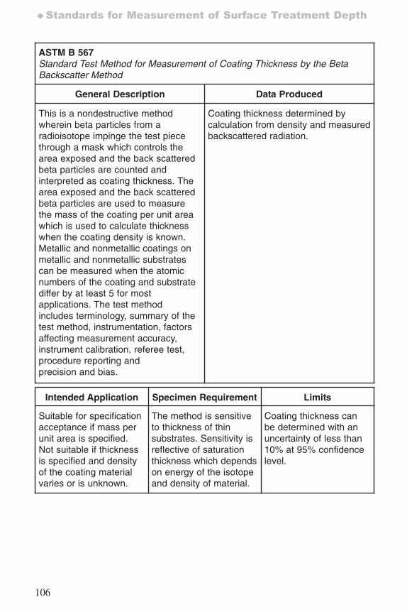
106
♦Standards for Measurement of Surface Treatment Depth
ASTM B 567 Standard Test Method for Measurement of Coating Thickness by the BetaBackscatter Method
General Description Data Produced
This is a nondestructive methodwherein beta particles from aradioisotope impinge the test piecethrough a mask which controls thearea exposed and the back scatteredbeta particles are counted andinterpreted as coating thickness. Thearea exposed and the back scatteredbeta particles are used to measurethe mass of the coating per unit areawhich is used to calculate thicknesswhen the coating density is known.Metallic and nonmetallic coatings onmetallic and nonmetallic substratescan be measured when the atomicnumbers of the coating and substratediffer by at least 5 for mostapplications. The test methodincludes terminology, summary of thetest method, instrumentation, factorsaffecting measurement accuracy,instrument calibration, referee test,procedure reporting andprecision and bias.
Coating thickness determined bycalculation from density and measuredbackscattered radiation.
Intended Application Specimen Requirement Limits
Suitable for specificationacceptance if mass perunit area is specified.Not suitable if thicknessis specified and densityof the coating materialvaries or is unknown.
The method is sensitiveto thickness of thinsubstrates. Sensitivity isreflective of saturationthickness which dependson energy of the isotopeand density of material.
Coating thickness canbe determined with anuncertainty of less than10% at 95% confidencelevel.
7652_.qxd 9/27/2005 11:58 AM Page 106
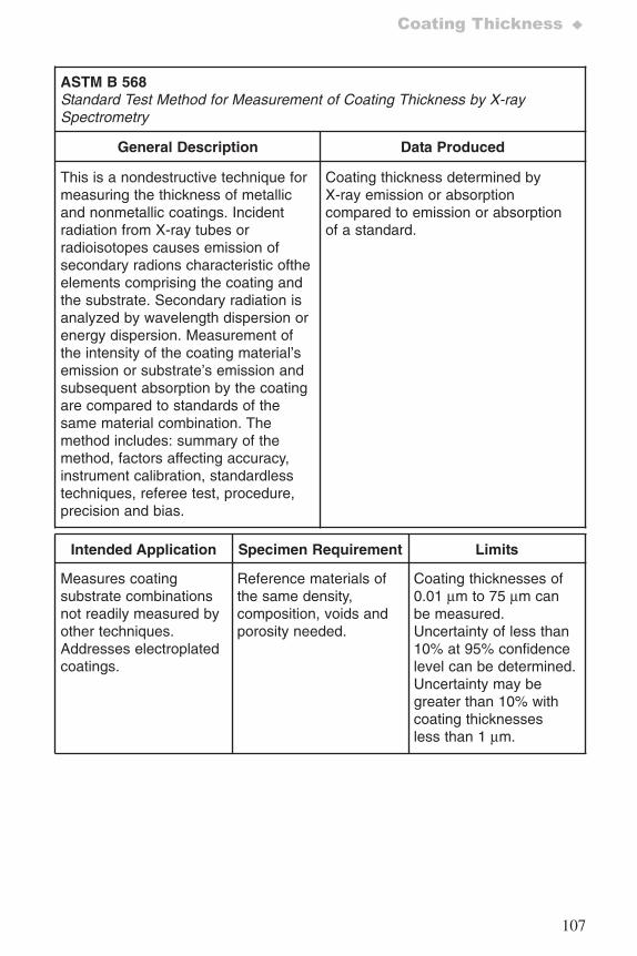
107
Coating Thickness ♦
ASTM B 568 Standard Test Method for Measurement of Coating Thickness by X-raySpectrometry
General Description Data Produced
This is a nondestructive technique formeasuring the thickness of metallicand nonmetallic coatings. Incidentradiation from X-ray tubes orradioisotopes causes emission ofsecondary radions characteristic oftheelements comprising the coating andthe substrate. Secondary radiation isanalyzed by wavelength dispersion orenergy dispersion. Measurement ofthe intensity of the coating material’semission or substrate’s emission andsubsequent absorption by the coatingare compared to standards of thesame material combination. Themethod includes: summary of themethod, factors affecting accuracy,instrument calibration, standardlesstechniques, referee test, procedure,precision and bias.
Coating thickness determined byX-ray emission or absorptioncompared to emission or absorptionof a standard.
Intended Application Specimen Requirement Limits
Measures coatingsubstrate combinationsnot readily measured byother techniques.Addresses electroplatedcoatings.
Reference materials ofthe same density,composition, voids andporosity needed.
Coating thicknesses of0.01 μm to 75 μm canbe measured.Uncertainty of less than10% at 95% confidencelevel can be determined.Uncertainty may begreater than 10% withcoating thicknessesless than 1 μm.
7652_.qxd 9/27/2005 11:58 AM Page 107
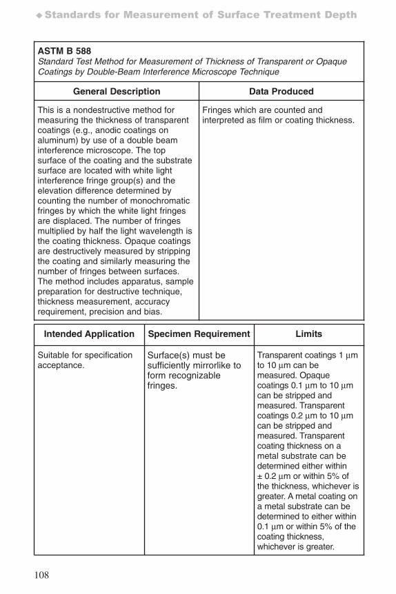
108
♦Standards for Measurement of Surface Treatment Depth
ASTM B 588 Standard Test Method for Measurement of Thickness of Transparent or OpaqueCoatings by Double-Beam Interference Microscope Technique
General Description Data Produced
This is a nondestructive method formeasuring the thickness of transparentcoatings (e.g., anodic coatings onaluminum) by use of a double beaminterference microscope. The topsurface of the coating and the substratesurface are located with white lightinterference fringe group(s) and theelevation difference determined bycounting the number of monochromaticfringes by which the white light fringesare displaced. The number of fringesmultiplied by half the light wavelength isthe coating thickness. Opaque coatingsare destructively measured by strippingthe coating and similarly measuring thenumber of fringes between surfaces.The method includes apparatus, samplepreparation for destructive technique,thickness measurement, accuracyrequirement, precision and bias.
Fringes which are counted andinterpreted as film or coating thickness.
Intended Application Specimen Requirement Limits
Suitable for specificationacceptance.
Surface(s) must besufficiently mirrorlike toform recognizablefringes.
Transparent coatings 1 μmto 10 μm can bemeasured. Opaquecoatings 0.1 μm to 10 μmcan be stripped andmeasured. Transparentcoatings 0.2 μm to 10 μmcan be stripped andmeasured. Transparentcoating thickness on ametal substrate can bedetermined either within ± 0.2 μm or within 5% ofthe thickness, whichever isgreater. A metal coating ona metal substrate can bedetermined to either within0.1 μm or within 5% of thecoating thickness,whichever is greater.
7652_.qxd 9/27/2005 11:58 AM Page 108
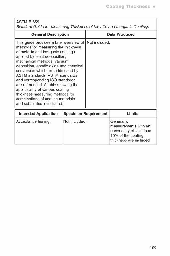
109
Coating Thickness ♦
ASTM B 659Standard Guide for Measuring Thickness of Metallic and Inorganic Coatings
General Description Data Produced
This guide provides a brief overview ofmethods for measuring the thicknessof metallic and inorganic coatingsapplied by electrodeposition,mechanical methods, vacuumdeposition, anodic oxide and chemicalconversion which are addressed byASTM standards. ASTM standardsand corresponding ISO standardsare referenced. A table showing theapplicability of various coatingthickness measuring methods forcombinations of coating materialsand substrates is included.
Not included.
Intended Application Specimen Requirement Limits
Acceptance testing. Not included. Generally,measurements with anuncertainty of less than10% of the coatingthickness are included.
7652_.qxd 9/27/2005 11:58 AM Page 109
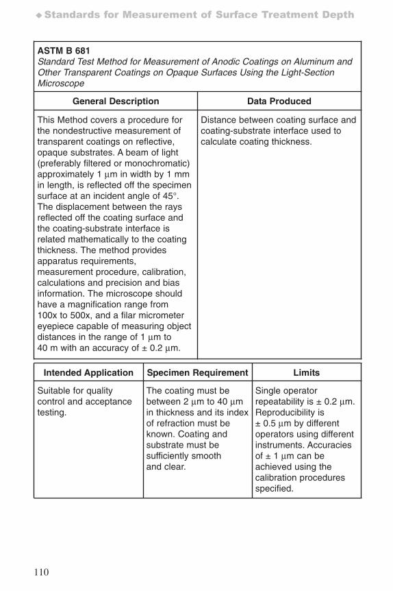
110
♦Standards for Measurement of Surface Treatment Depth
ASTM B 681 Standard Test Method for Measurement of Anodic Coatings on Aluminum andOther Transparent Coatings on Opaque Surfaces Using the Light-SectionMicroscope
General Description Data Produced
This Method covers a procedure forthe nondestructive measurement oftransparent coatings on reflective,opaque substrates. A beam of light(preferably filtered or monochromatic)approximately 1 μm in width by 1 mmin length, is reflected off the specimensurface at an incident angle of 45°.The displacement between the raysreflected off the coating surface andthe coating-substrate interface isrelated mathematically to the coatingthickness. The method providesapparatus requirements,measurement procedure, calibration,calculations and precision and biasinformation. The microscope shouldhave a magnification range from100x to 500x, and a filar micrometereyepiece capable of measuring objectdistances in the range of 1 μm to40 m with an accuracy of ± 0.2 μm.
Distance between coating surface andcoating-substrate interface used tocalculate coating thickness.
Intended Application Specimen Requirement Limits
Suitable for qualitycontrol and acceptancetesting.
The coating must bebetween 2 μm to 40 μmin thickness and its indexof refraction must beknown. Coating andsubstrate must besufficiently smoothand clear.
Single operatorrepeatability is ± 0.2 μm.Reproducibility is± 0.5 μm by differentoperators using differentinstruments. Accuraciesof ± 1 μm can beachieved using thecalibration proceduresspecified.
7652_.qxd 9/27/2005 11:58 AM Page 110
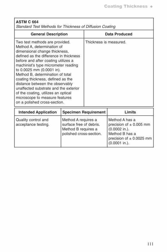
111
Coating Thickness ♦
ASTM C 664Standard Test Methods for Thickness of Diffusion Coating
General Description Data Produced
Two test methods are provided.Method A, determination ofdimensional change thickness,defined as the difference in thicknessbefore and after coating utilizes amachinist’s type micrometer readingto 0.0025 mm (0.0001 in).Method B, determination of totalcoating thickness, defined as thedistance between the observablyunaffected substrate and the exteriorof the coating, utilizes an opticalmicroscope to measure featureson a polished cross-section.
Thickness is measured.
Intended Application Specimen Requirement Limits
Quality control andacceptance testing.
Method A requires asurface free of debris.Method B requires apolished cross-section.
Method A has aprecision of ± 0.005 mm(0.0002 in.).Method B has aprecision of ± 0.0025 mm(0.0001 in.).
7652_.qxd 9/27/2005 11:58 AM Page 111
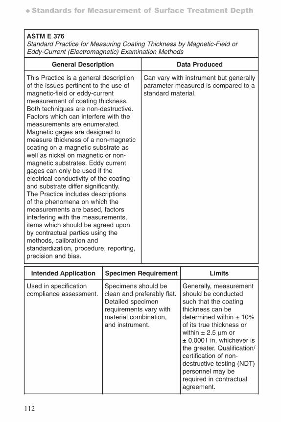
112
♦Standards for Measurement of Surface Treatment Depth
ASTM E 376Standard Practice for Measuring Coating Thickness by Magnetic-Field orEddy-Current (Electromagnetic) Examination Methods
General Description Data Produced
This Practice is a general descriptionof the issues pertinent to the use ofmagnetic-field or eddy-currentmeasurement of coating thickness.Both techniques are non-destructive.Factors which can interfere with themeasurements are enumerated.Magnetic gages are designed tomeasure thickness of a non-magneticcoating on a magnetic substrate aswell as nickel on magnetic or non-magnetic substrates. Eddy currentgages can only be used if theelectrical conductivity of the coatingand substrate differ significantly.The Practice includes descriptionsof the phenomena on which themeasurements are based, factorsinterfering with the measurements,items which should be agreed uponby contractual parties using themethods, calibration andstandardization, procedure, reporting,precision and bias.
Can vary with instrument but generallyparameter measured is compared to astandard material.
Intended Application Specimen Requirement Limits
Used in specificationcompliance assessment.
Specimens should beclean and preferably flat.Detailed specimenrequirements vary withmaterial combination,and instrument.
Generally, measurementshould be conductedsuch that the coatingthickness can bedetermined within ± 10%of its true thickness orwithin ± 2.5 μm or± 0.0001 in, whichever isthe greater. Qualification/certification of non-destructive testing (NDT)personnel may berequired in contractualagreement.
7652_.qxd 9/27/2005 11:58 AM Page 112
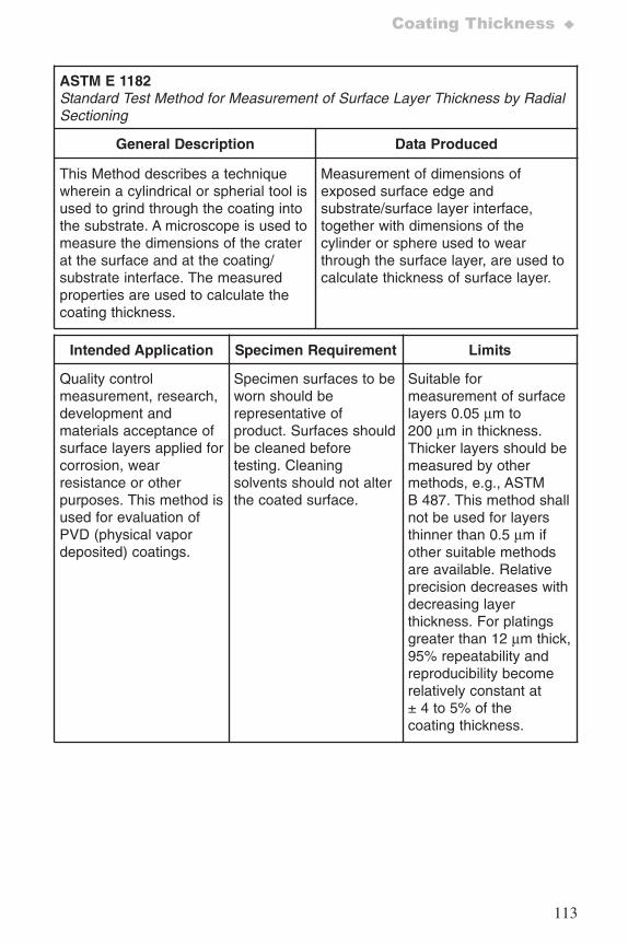
113
Coating Thickness ♦
ASTM E 1182Standard Test Method for Measurement of Surface Layer Thickness by RadialSectioning
General Description Data Produced
This Method describes a techniquewherein a cylindrical or spherial tool isused to grind through the coating intothe substrate. A microscope is used tomeasure the dimensions of the craterat the surface and at the coating/substrate interface. The measuredproperties are used to calculate thecoating thickness.
Measurement of dimensions ofexposed surface edge andsubstrate/surface layer interface,together with dimensions of thecylinder or sphere used to wearthrough the surface layer, are used tocalculate thickness of surface layer.
Intended Application Specimen Requirement Limits
Quality controlmeasurement, research,development andmaterials acceptance ofsurface layers applied forcorrosion, wearresistance or otherpurposes. This method isused for evaluation ofPVD (physical vapordeposited) coatings.
Specimen surfaces to beworn should berepresentative ofproduct. Surfaces shouldbe cleaned beforetesting. Cleaningsolvents should not alterthe coated surface.
Suitable formeasurement of surfacelayers 0.05 μm to200 μm in thickness.Thicker layers should bemeasured by othermethods, e.g., ASTMB 487. This method shallnot be used for layersthinner than 0.5 μm ifother suitable methodsare available. Relativeprecision decreases withdecreasing layerthickness. For platingsgreater than 12 μm thick,95% repeatability andreproducibility becomerelatively constant at± 4 to 5% of thecoating thickness.
7652_.qxd 9/27/2005 11:58 AM Page 113
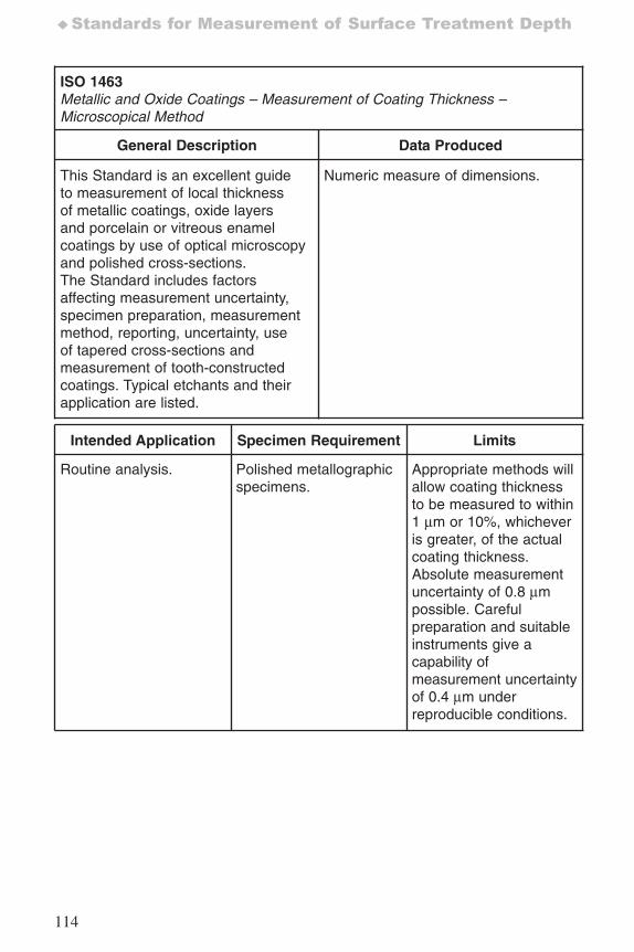
114
♦Standards for Measurement of Surface Treatment Depth
ISO 1463Metallic and Oxide Coatings – Measurement of Coating Thickness –Microscopical Method
General Description Data Produced
This Standard is an excellent guideto measurement of local thicknessof metallic coatings, oxide layersand porcelain or vitreous enamelcoatings by use of optical microscopyand polished cross-sections.The Standard includes factorsaffecting measurement uncertainty,specimen preparation, measurementmethod, reporting, uncertainty, useof tapered cross-sections andmeasurement of tooth-constructedcoatings. Typical etchants and theirapplication are listed.
Numeric measure of dimensions.
Intended Application Specimen Requirement Limits
Routine analysis. Polished metallographicspecimens.
Appropriate methods willallow coating thicknessto be measured to within1 μm or 10%, whicheveris greater, of the actualcoating thickness. Absolute measurementuncertainty of 0.8 μmpossible. Carefulpreparation and suitableinstruments give acapability ofmeasurement uncertaintyof 0.4 μm underreproducible conditions.
7652_.qxd 9/27/2005 11:58 AM Page 114
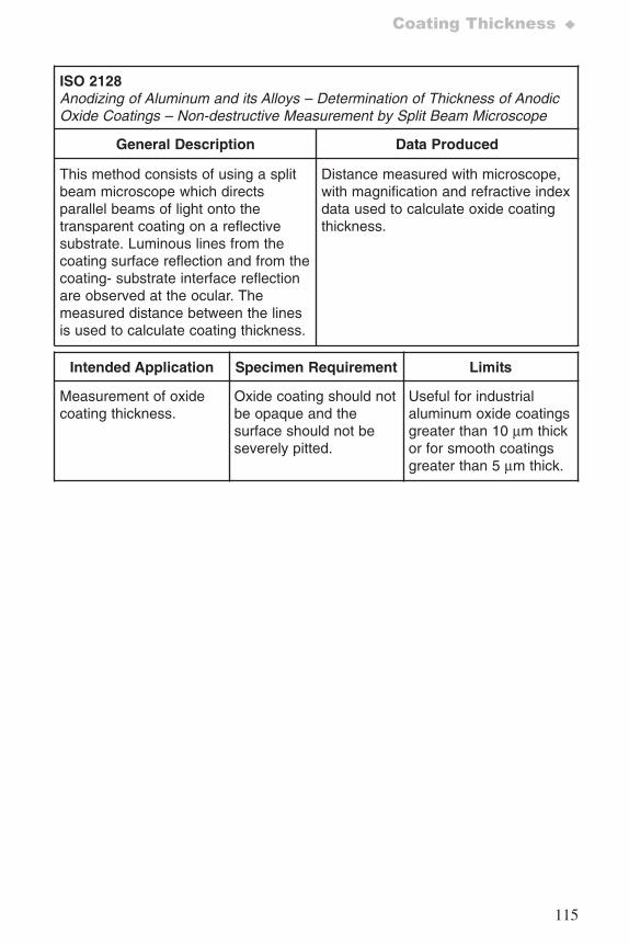
115
Coating Thickness ♦
ISO 2128Anodizing of Aluminum and its Alloys – Determination of Thickness of AnodicOxide Coatings – Non-destructive Measurement by Split Beam Microscope
General Description Data Produced
This method consists of using a splitbeam microscope which directsparallel beams of light onto thetransparent coating on a reflectivesubstrate. Luminous lines from thecoating surface reflection and from thecoating- substrate interface reflectionare observed at the ocular. Themeasured distance between the linesis used to calculate coating thickness.
Distance measured with microscope,with magnification and refractive indexdata used to calculate oxide coatingthickness.
Intended Application Specimen Requirement Limits
Measurement of oxidecoating thickness.
Oxide coating should notbe opaque and thesurface should not beseverely pitted.
Useful for industrialaluminum oxide coatingsgreater than 10 μm thickor for smooth coatingsgreater than 5 μm thick.
7652_.qxd 9/27/2005 11:58 AM Page 115
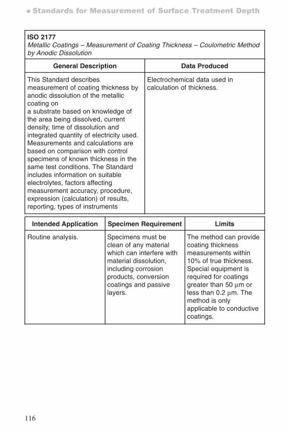
116
♦Standards for Measurement of Surface Treatment Depth
ISO 2177Metallic Coatings – Measurement of Coating Thickness – Coulometric Methodby Anodic Dissolution
General Description Data Produced
This Standard describesmeasurement of coating thickness byanodic dissolution of the metalliccoating ona substrate based on knowledge ofthe area being dissolved, currentdensity, time of dissolution andintegrated quantity of electricity used.Measurements and calculations arebased on comparison with controlspecimens of known thickness in thesame test conditions. The Standardincludes information on suitableelectrolytes, factors affectingmeasurement accuracy, procedure,expression (calculation) of results,reporting, types of instruments
Electrochemical data used incalculation of thickness.
Intended Application Specimen Requirement Limits
Routine analysis. Specimens must beclean of any materialwhich can interfere withmaterial dissolution,including corrosionproducts, conversioncoatings and passivelayers.
The method can providecoating thicknessmeasurements within10% of true thickness.Special equipment isrequired for coatingsgreater than 50 μm orless than 0.2 μm. Themethod is onlyapplicable to conductivecoatings.
7652_.qxd 9/27/2005 11:58 AM Page 116
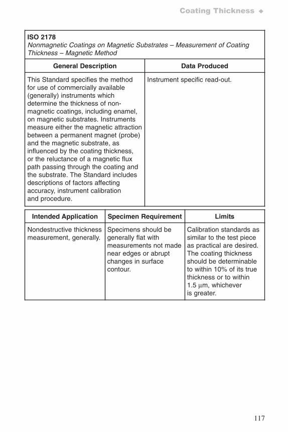
117
Coating Thickness ♦
ISO 2178Nonmagnetic Coatings on Magnetic Substrates – Measurement of CoatingThickness – Magnetic Method
General Description Data Produced
This Standard specifies the methodfor use of commercially available(generally) instruments whichdetermine the thickness of non-magnetic coatings, including enamel,on magnetic substrates. Instrumentsmeasure either the magnetic attractionbetween a permanent magnet (probe)and the magnetic substrate, asinfluenced by the coating thickness,or the reluctance of a magnetic fluxpath passing through the coating andthe substrate. The Standard includesdescriptions of factors affectingaccuracy, instrument calibrationand procedure.
Instrument specific read-out.
Intended Application Specimen Requirement Limits
Nondestructive thicknessmeasurement, generally.
Specimens should begenerally flat withmeasurements not madenear edges or abruptchanges in surfacecontour.
Calibration standards assimilar to the test pieceas practical are desired.The coating thicknessshould be determinableto within 10% of its truethickness or to within1.5 μm, whicheveris greater.
7652_.qxd 9/27/2005 11:58 AM Page 117
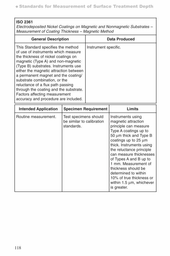
118
♦Standards for Measurement of Surface Treatment Depth
ISO 2361Electrodeposited Nickel Coatings on Magnetic and Nonmagnetic Substrates –Measurement of Coating Thickness – Magnetic Method
General Description Data Produced
This Standard specifies the methodof use of instruments which measurethe thickness of nickel coatings onmagnetic (Type A) and non-magnetic(Type B) substrates. Instruments useeither the magnetic attraction betweena permanent magnet and the coating/substrate combination, or thereluctance of a flux path passingthrough the coating and the substrate.Factors affecting measurementaccuracy and procedure are included.
Instrument specific.
Intended Application Specimen Requirement Limits
Routine measurement. Test specimens shouldbe similar to calibrationstandards.
Instruments usingmagnetic attractionprinciple can measureType A coatings up to50 μm thick and Type Bcoatings up to 25 μmthick. Instruments usingthe reluctance principlecan measure thicknessesof Types A and B up to1 mm. Measurement ofthickness should bedetermined to within10% of true thickness orwithin 1.5 μm, whicheveris greater.
7652_.qxd 9/27/2005 11:58 AM Page 118
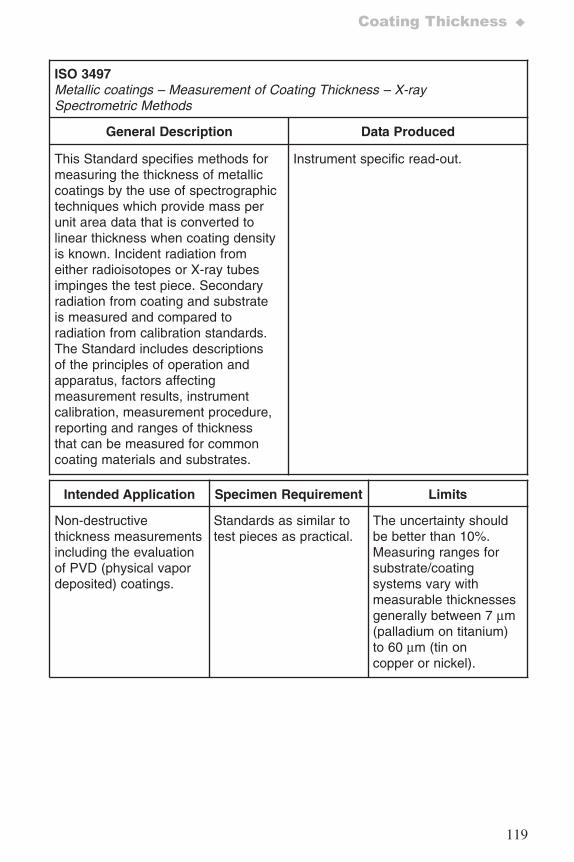
119
Coating Thickness ♦
ISO 3497Metallic coatings – Measurement of Coating Thickness – X-raySpectrometric Methods
General Description Data Produced
This Standard specifies methods formeasuring the thickness of metalliccoatings by the use of spectrographictechniques which provide mass perunit area data that is converted tolinear thickness when coating densityis known. Incident radiation fromeither radioisotopes or X-ray tubesimpinges the test piece. Secondaryradiation from coating and substrateis measured and compared toradiation from calibration standards.The Standard includes descriptionsof the principles of operation andapparatus, factors affectingmeasurement results, instrumentcalibration, measurement procedure,reporting and ranges of thicknessthat can be measured for commoncoating materials and substrates.
Instrument specific read-out.
Intended Application Specimen Requirement Limits
Non-destructivethickness measurementsincluding the evaluationof PVD (physical vapordeposited) coatings.
Standards as similar totest pieces as practical.
The uncertainty shouldbe better than 10%.Measuring ranges forsubstrate/coatingsystems vary withmeasurable thicknessesgenerally between 7 μm(palladium on titanium)to 60 μm (tin oncopper or nickel).
7652_.qxd 9/27/2005 11:58 AM Page 119
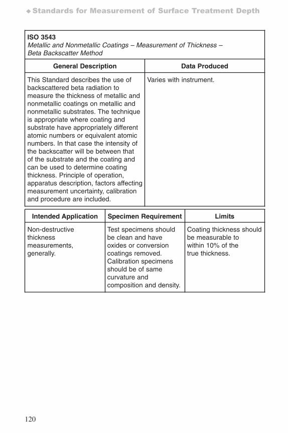
120
♦Standards for Measurement of Surface Treatment Depth
ISO 3543Metallic and Nonmetallic Coatings – Measurement of Thickness – Beta Backscatter Method
General Description Data Produced
This Standard describes the use ofbackscattered beta radiation tomeasure the thickness of metallic andnonmetallic coatings on metallic andnonmetallic substrates. The techniqueis appropriate where coating andsubstrate have appropriately differentatomic numbers or equivalent atomicnumbers. In that case the intensity ofthe backscatter will be between thatof the substrate and the coating andcan be used to determine coatingthickness. Principle of operation,apparatus description, factors affectingmeasurement uncertainty, calibrationand procedure are included.
Varies with instrument.
Intended Application Specimen Requirement Limits
Non-destructivethicknessmeasurements,generally.
Test specimens shouldbe clean and haveoxides or conversioncoatings removed.Calibration specimensshould be of samecurvature andcomposition and density.
Coating thickness shouldbe measurable towithin 10% of thetrue thickness.
7652_.qxd 9/27/2005 11:58 AM Page 120
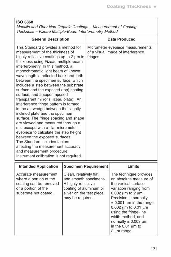
121
Coating Thickness ♦
ISO 3868Metallic and Oher Non-Organic Coatings – Measurement of CoatingThickness – Fizeau Multiple-Beam Interferometry Method
General Description Data Produced
This Standard provides a method formeasurement of the thickness ofhighly reflective coatings up to 2 μm inthickness using Fizeau multiple-beaminterferometry. In this method, amonochromatic light beam of knownwavelength is reflected back and forthbetween the specimen surface, whichincludes a step between the substratesurface and the exposed (top) coatingsurface, and a superimposedtransparent mirror (Fizeau plate). Aninterference fringe pattern is formedin the air wedge between the slightlyinclined plate and the specimensurface. The fringe spacing and shapeare viewed and measured through amicroscope with a filar micrometereyepiece to calculate the step heightbetween the exposed surfaces.The Standard includes factorsaffecting the measurement accuracyand measurement procedure.Instrument calibration is not required.
Micrometer eyepiece measurementsof a visual image of interferencefringes.
Intended Application Specimen Requirement Limits
Accurate measurementwhere a portion of thecoating can be removedor a portion of thesubstrate not coated.
Clean, relatively flatand smooth specimens. A highly reflectivecoating of aluminum orsilver on the test piecemay be required.
The technique providesan absolute measure ofthe vertical surfacevariation ranging from0.002 μm to 2 μm.Precision is normally± 0.001 μm in the range0.002 μm to 0.01 μmusing the fringe-linewidth method, andnormally ± 0.003 μmin the 0.01 μm to2 μm range.
7652_.qxd 9/27/2005 11:58 AM Page 121
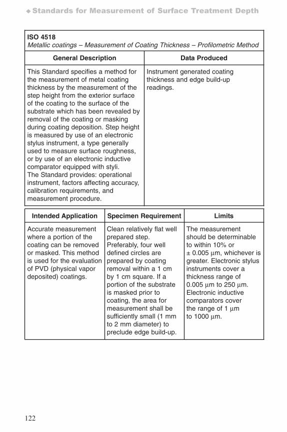
122
♦Standards for Measurement of Surface Treatment Depth
ISO 4518Metallic coatings – Measurement of Coating Thickness – Profilometric Method
General Description Data Produced
This Standard specifies a method forthe measurement of metal coatingthickness by the measurement of thestep height from the exterior surfaceof the coating to the surface of thesubstrate which has been revealed byremoval of the coating or maskingduring coating deposition. Step heightis measured by use of an electronicstylus instrument, a type generallyused to measure surface roughness,or by use of an electronic inductivecomparator equipped with styli.The Standard provides: operationalinstrument, factors affecting accuracy,calibration requirements, andmeasurement procedure.
Instrument generated coatingthickness and edge build-upreadings.
Intended Application Specimen Requirement Limits
Accurate measurementwhere a portion of thecoating can be removedor masked. This methodis used for the evaluationof PVD (physical vapordeposited) coatings.
Clean relatively flat wellprepared step.Preferably, four welldefined circles areprepared by coatingremoval within a 1 cmby 1 cm square. If aportion of the substrateis masked prior tocoating, the area formeasurement shall besufficiently small (1 mmto 2 mm diameter) topreclude edge build-up.
The measurementshould be determinableto within 10% or± 0.005 μm, whichever isgreater. Electronic stylusinstruments cover athickness range of0.005 μm to 250 μm.Electronic inductivecomparators coverthe range of 1 μmto 1000 μm.
7652_.qxd 9/27/2005 11:58 AM Page 122
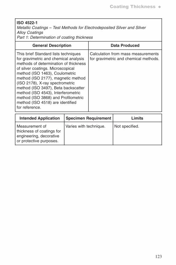
123
Coating Thickness ♦
ISO 4522-1Metallic Coatings – Test Methods for Electrodeposited Silver and SilverAlloy CoatingsPart 1: Determination of coating thickness
General Description Data Produced
This brief Standard lists techniquesfor gravimetric and chemical analysismethods of determination of thicknessof silver coatings. Microscopicalmethod (ISO 1463), Coulometricmethod (ISO 2177), magnetic method(ISO 2178), X-ray spectrometricmethod (ISO 3497), Beta backscattermethod (ISO 4543), Interferometricmethod (ISO 3868) and Profilometricmethod (ISO 4518) are identifiedfor reference.
Calculation from mass measurementsfor gravimetric and chemical methods.
Intended Application Specimen Requirement Limits
Measurement ofthickness of coatings forengineering, decorativeor protective purposes.
Varies with technique. Not specified.
7652_.qxd 9/27/2005 11:58 AM Page 123
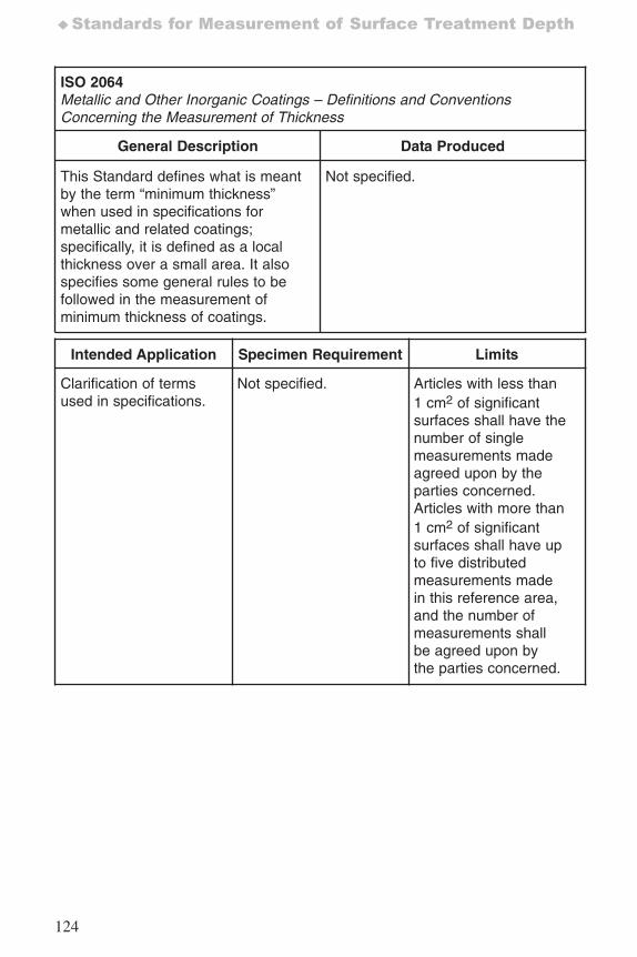
124
♦Standards for Measurement of Surface Treatment Depth
ISO 2064Metallic and Other Inorganic Coatings – Definitions and ConventionsConcerning the Measurement of Thickness
General Description Data Produced
This Standard defines what is meantby the term “minimum thickness”when used in specifications formetallic and related coatings;specifically, it is defined as a localthickness over a small area. It alsospecifies some general rules to befollowed in the measurement ofminimum thickness of coatings.
Not specified.
Intended Application Specimen Requirement Limits
Clarification of termsused in specifications.
Not specified. Articles with less than1 cm2 of significantsurfaces shall have thenumber of singlemeasurements madeagreed upon by theparties concerned.Articles with more than1 cm2 of significantsurfaces shall have upto five distributedmeasurements madein this reference area,and the number ofmeasurements shallbe agreed upon bythe parties concerned.
7652_.qxd 9/27/2005 11:58 AM Page 124
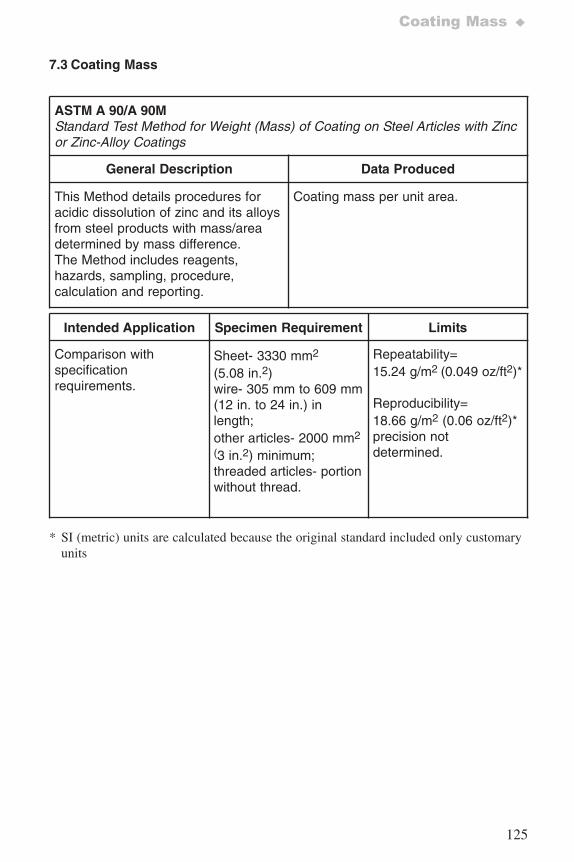
125
Coating Mass ♦
7.3 Coating Mass
ASTM A 90/A 90MStandard Test Method for Weight (Mass) of Coating on Steel Articles with Zincor Zinc-Alloy Coatings
General Description Data Produced
This Method details procedures foracidic dissolution of zinc and its alloysfrom steel products with mass/areadetermined by mass difference.The Method includes reagents,hazards, sampling, procedure,calculation and reporting.
Coating mass per unit area.
Intended Application Specimen Requirement Limits
Comparison withspecificationrequirements.
Sheet- 3330 mm2
(5.08 in.2)wire- 305 mm to 609 mm(12 in. to 24 in.) inlength;other articles- 2000 mm2
(3 in.2) minimum;threaded articles- portionwithout thread.
Repeatability=15.24 g/m2 (0.049 oz/ft2)*
Reproducibility=18.66 g/m2 (0.06 oz/ft2)*precision notdetermined.
* SI (metric) units are calculated because the original standard included only customaryunits
7652_.qxd 9/27/2005 11:58 AM Page 125
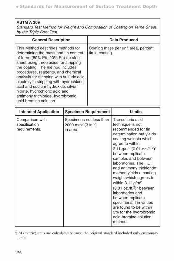
126
♦Standards for Measurement of Surface Treatment Depth
ASTM A 309Standard Test Method for Weight and Composition of Coating on Terne Sheetby the Triple Spot Test
General Description Data Produced
This Method describes methods fordetermining the mass and tin contentof terne (80% Pb, 20% Sn) on steelsheet using three acids for strippingthe coating. The method includesprocedures, reagents, and chemicalanalysis for stripping with sulfuric acid,electrolytic stripping with hydrochloricacid and sodium hydroxide, silvernitrate, hydrochloric acid andantimony trichloride, hydrobromicacid-bromine solution.
Coating mass per unit area, percenttin in coating.
Intended Application Specimen Requirement Limits
Comparison withspecificationrequirements.
Specimens not less than2000 mm2 (3 in.2)in area.
The sulfuric acidtechnique is notrecommended for tindetermination but yieldscoating weights whichagree to within3.11 g/m2 (0.01 oz./ft.2)*between replicatesamples and betweenlaboratories. The HCland antimony trichloridemethod yields a coatingweight which agrees towithin 3.11 g/m2
(0.01 oz./ft.2)* betweenlaboratories andbetween replicatespecimens. Tin valuesare found to be within3% for the hydrobromicacid-bromine solutionmethod.
* SI (metric) units are calculated because the original standard included only customaryunits
7652_.qxd 9/27/2005 11:58 AM Page 126
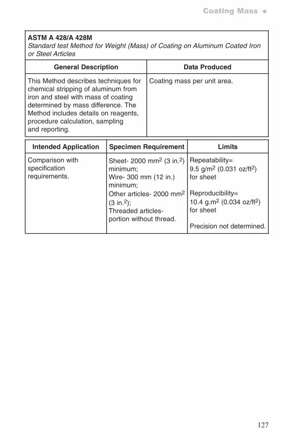
127
Coating Mass ♦
ASTM A 428/A 428M Standard test Method for Weight (Mass) of Coating on Aluminum Coated Ironor Steel Articles
General Description Data Produced
This Method describes techniques forchemical stripping of aluminum fromiron and steel with mass of coatingdetermined by mass difference. TheMethod includes details on reagents,procedure calculation, samplingand reporting.
Coating mass per unit area.
Intended Application Specimen Requirement Limits
Comparison withspecificationrequirements.
Sheet- 2000 mm2 (3 in.2)minimum;Wire- 300 mm (12 in.)minimum; Other articles- 2000 mm2
(3 in.2);Threaded articles-portion without thread.
Repeatability=9.5 g/m2 (0.031 oz/ft2)for sheet
Reproducibility=10.4 g.m2 (0.034 oz/ft2)for sheet
Precision not determined.
7652_.qxd 9/27/2005 11:58 AM Page 127
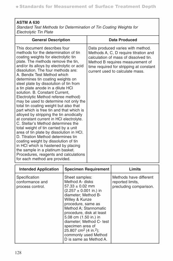
128
♦Standards for Measurement of Surface Treatment Depth
ASTM A 630 Standard Test Methods for Determination of Tin Coating Weights forElectrolytic Tin Plate
General Description Data Produced
This document describes fourmethods for the determination of tincoating weights for electrolytic tinplate. The methods remove the tin,and/or its alloys by electrolytic or aciddissolution. The four methods are:A. Bendix Test Method whichdetermines tin coating weights onsteel plate by dissolution of tin froma tin plate anode in a dilute HClsolution. B. Constant Current,Electrolytic Method referee method)may be used to determine not only thetotal tin coating weight but also thatpart which is free tin and that which isalloyed by stripping the tin anodicallyat constant current in HCl electrolyte.C. Stellar’s Method determines thetotal weight of tin carried by a unitarea of tin plate by dissolution in HCl.D. Titration Method determines tincoating weight by dissolution of tinin HCl which is hastened by placingthe sample in a platinum basket.Procedures, reagents and calculationsfor each method are provided.
Data produced varies with method.Methods A, C, D require titration andcalculation of mass of dissolved tin.Method B requires measurement oftime required for stripping at constantcurrent used to calculate mass.
Intended Application Specimen Requirement Limits
Specificationconformance andprocess control.
Sheet samples:Method A- disks57.33 ± 0.02 mm(2.257 ± 0.001 in.) indiameter; Method B-Willey & Kunzeprocedure, same asMethod A; Stannomaticprocedure, disk at least5.08 cm (1.50 in.) indiameter; Method C- testspecimen area of25.807 cm2 (4 in.2);commonly used MethodD is same as Method A.
Methods have differentreported limits,precluding comparison.
7652_.qxd 9/27/2005 11:58 AM Page 128
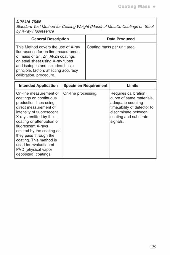
129
Coating Mass ♦
A 754/A 754M Standard Test Method for Coating Weight (Mass) of Metallic Coatings on Steelby X-ray Fluoresence
General Description Data Produced
This Method covers the use of X-rayfluoresence for on-line measurementof mass of Sn, Zn, Al-Zn coatingson steel sheet using X-ray tubesand isotopes and includes: basicprinciple, factors affecting accuracycalibration, procedure.
Coating mass per unit area.
Intended Application Specimen Requirement Limits
On-line measurement ofcoatings on continuousproduction lines usingdirect measurement ofintensity of fluoresecentX-rays emitted by thecoating or attenuation offluorescent X-raysemitted by the coating asthey pass through thecoating. This method isused for evaluation ofPVD (physical vapordeposited) coatings.
On-line processing. Requires calibrationcurve of same materials,adequate countingtime,ability of detector todiscriminate betweencoating and substratesignals.
7652_.qxd 9/27/2005 11:58 AM Page 129
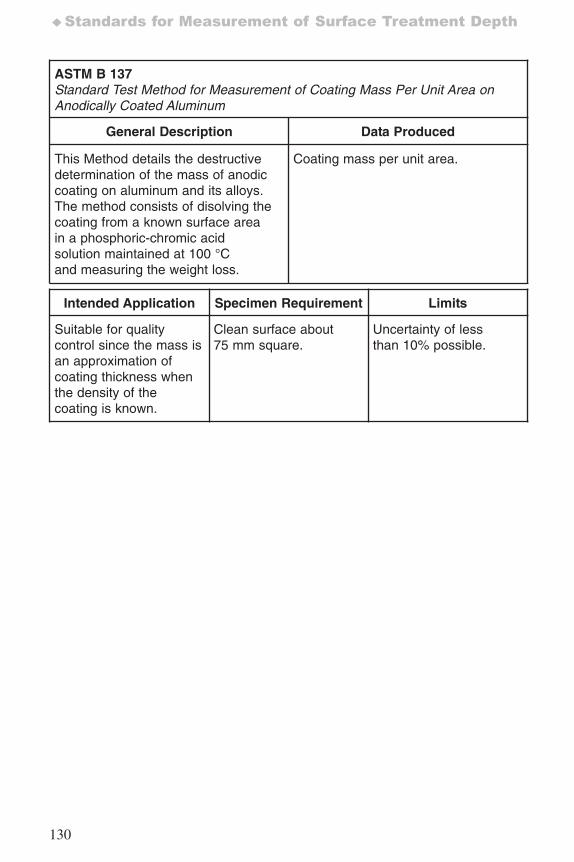
130
♦Standards for Measurement of Surface Treatment Depth
ASTM B 137Standard Test Method for Measurement of Coating Mass Per Unit Area onAnodically Coated Aluminum
General Description Data Produced
This Method details the destructivedetermination of the mass of anodiccoating on aluminum and its alloys.The method consists of disolving thecoating from a known surface areain a phosphoric-chromic acidsolution maintained at 100 °Cand measuring the weight loss.
Coating mass per unit area.
Intended Application Specimen Requirement Limits
Suitable for qualitycontrol since the mass isan approximation ofcoating thickness whenthe density of thecoating is known.
Clean surface about75 mm square.
Uncertainty of lessthan 10% possible.
7652_.qxd 9/27/2005 11:58 AM Page 130
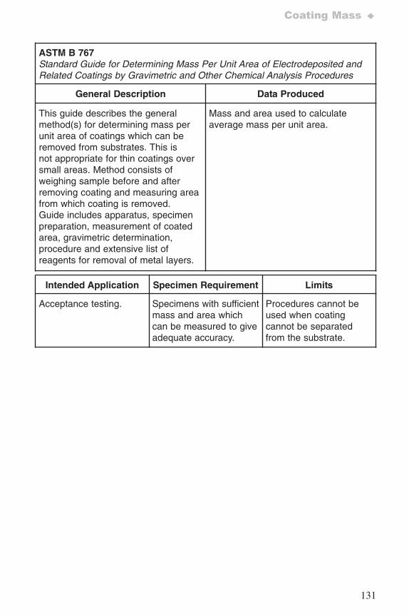
131
Coating Mass ♦
ASTM B 767Standard Guide for Determining Mass Per Unit Area of Electrodeposited andRelated Coatings by Gravimetric and Other Chemical Analysis Procedures
General Description Data Produced
This guide describes the generalmethod(s) for determining mass perunit area of coatings which can beremoved from substrates. This isnot appropriate for thin coatings oversmall areas. Method consists ofweighing sample before and afterremoving coating and measuring areafrom which coating is removed.Guide includes apparatus, specimenpreparation, measurement of coatedarea, gravimetric determination,procedure and extensive list ofreagents for removal of metal layers.
Mass and area used to calculateaverage mass per unit area.
Intended Application Specimen Requirement Limits
Acceptance testing. Specimens with sufficientmass and area whichcan be measured to giveadequate accuracy.
Procedures cannot beused when coatingcannot be separatedfrom the substrate.
7652_.qxd 9/27/2005 11:58 AM Page 131
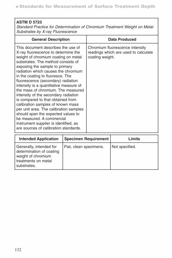
132
♦Standards for Measurement of Surface Treatment Depth
ASTM D 5723Standard Practice for Determination of Chromium Treatment Weight on MetalSubstrates by X-ray Fluorescence
General Description Data Produced
This document describes the use ofX-ray fluorescence to determine theweight of chromium coating on metalsubstrates. The method consists ofexposing the sample to primaryradiation which causes the chromiumin the coating to fluoresce. Thefluorescence (secondary) radiationintensity is a quantitative measure ofthe mass of chromium. The measuredintensity of the secondary radiationis compared to that obtained fromcalibration samples of known massper unit area. The calibration samplesshould span the expected values tobe measured. A commercialinstrument supplier is identified, asare sources of calibration standards.
Chromium fluorescence intensityreadings which are used to calculatecoating weight.
Intended Application Specimen Requirement Limits
Generally, intended fordetermination of coatingweight of chromiumtreatments on metalsubstrates.
Flat, clean specimens. Not specified.
7652_.qxd 9/27/2005 11:58 AM Page 132
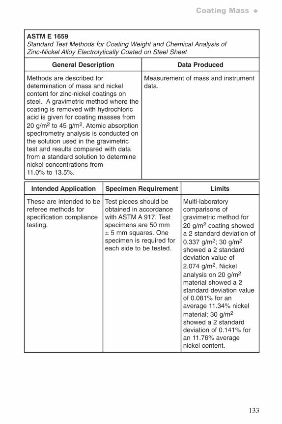
133
Coating Mass ♦
ASTM E 1659Standard Test Methods for Coating Weight and Chemical Analysis ofZinc-Nickel Alloy Electrolytically Coated on Steel Sheet
General Description Data Produced
Methods are described fordetermination of mass and nickelcontent for zinc-nickel coatings onsteel. A gravimetric method where thecoating is removed with hydrochloricacid is given for coating masses from20 g/m2 to 45 g/m2. Atomic absorptionspectrometry analysis is conducted onthe solution used in the gravimetrictest and results compared with datafrom a standard solution to determinenickel concentrations from11.0% to 13.5%.
Measurement of mass and instrumentdata.
Intended Application Specimen Requirement Limits
These are intended to bereferee methods forspecification compliancetesting.
Test pieces should beobtained in accordancewith ASTM A 917. Testspecimens are 50 mm ± 5 mm squares. Onespecimen is required foreach side to be tested.
Multi-laboratorycomparisons ofgravimetric method for20 g/m2 coating showeda 2 standard deviation of0.337 g/m2; 30 g/m2
showed a 2 standarddeviation value of2.074 g/m2. Nickelanalysis on 20 g/m2
material showed a 2standard deviation valueof 0.081% for anaverage 11.34% nickelmaterial; 30 g/m2
showed a 2 standarddeviation of 0.141% foran 11.76% averagenickel content.
7652_.qxd 9/27/2005 11:58 AM Page 133
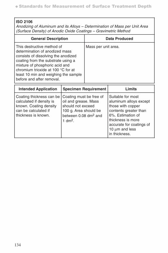
134
♦Standards for Measurement of Surface Treatment Depth
ISO 2106Anodizing of Aluminum and its Alloys – Determination of Mass per Unit Area(Surface Density) of Anodic Oxide Coatings – Gravimetric Method
General Description Data Produced
This destructive method ofdetermination of anodized massconsists of dissolving the anodizedcoating from the substrate using amixture of phosphoric acid andchromium trioxide at 100 °C for atleast 10 min and weighing the samplebefore and after removal.
Mass per unit area.
Intended Application Specimen Requirement Limits
Coating thickness can becalculated if density isknown. Coating densitycan be calculated ifthickness is known.
Coating must be free ofoil and grease. Massshould not exceed100 g. Area should bebetween 0.08 dm2 and1 dm2.
Suitable for mostaluminum alloys exceptthose with coppercontents greater than6%. Estimation ofthickness is moreaccurate for coatings of10 μm and lessin thickness.
7652_.qxd 9/27/2005 11:58 AM Page 134
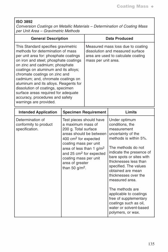
135
Coating Mass ♦
ISO 3892Conversion Coatings on Metallic Materials – Determination of Coating Massper Unit Area – Gravimetric Methods
General Description Data Produced
This Standard specifies gravimetricmethods for determination of massper unit area for: phosphate coatingson iron and steel; phosphate coatingson zinc and cadmium; phosphatecoatings on aluminum and its alloys;chromate coatings on zinc andcadmium; and, chromate coatings onaluminum and its alloys. Reagents fordissolution of coatings, specimensurface areas required for adequateaccuracy, procedures and safetywarnings are provided.
Measured mass loss due to coatingdissolution and measured surfacearea are used to calculate coatingmass per unit area.
Intended Application Specimen Requirement Limits
Determination ofconformity to productspecification.
Test pieces should havea maximum mass of200 g. Total surfaceareas should be between400 cm2 for expectedcoating mass per unitarea of less than 1 g/m2
and 25 cm2 for expectedcoating mass per unitarea of greaterthan 50 g/m2.
Under optimumconditions, themeasurementuncertainty of themethods is within 5%.
The methods do notindicate the presence ofbare spots or sites withthicknesses less thanspecified. The valuesobtained are meanthicknesses over themeasured area.
The methods areapplicable to coatingsfree of supplementarycoatings such as oil,water or solvent-basedpolymers, or wax.
7652_.qxd 9/27/2005 11:58 AM Page 135
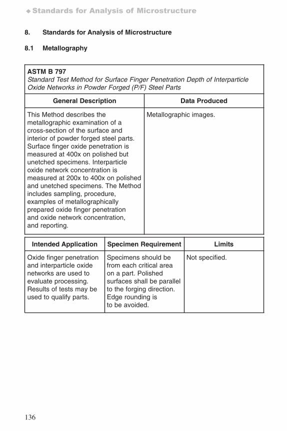
136
♦Standards for Analysis of Microstructure
8. Standards for Analysis of Microstructure
8.1 Metallography
ASTM B 797Standard Test Method for Surface Finger Penetration Depth of InterparticleOxide Networks in Powder Forged (P/F) Steel Parts
General Description Data Produced
This Method describes themetallographic examination of across-section of the surface andinterior of powder forged steel parts.Surface finger oxide penetration ismeasured at 400x on polished butunetched specimens. Interparticleoxide network concentration ismeasured at 200x to 400x on polishedand unetched specimens. The Methodincludes sampling, procedure,examples of metallographicallyprepared oxide finger penetrationand oxide network concentration,and reporting.
Metallographic images.
Intended Application Specimen Requirement Limits
Oxide finger penetrationand interparticle oxidenetworks are used toevaluate processing.Results of tests may beused to qualify parts.
Specimens should befrom each critical areaon a part. Polishedsurfaces shall be parallelto the forging direction.Edge rounding isto be avoided.
Not specified.
7652_.qxd 9/27/2005 11:58 AM Page 136
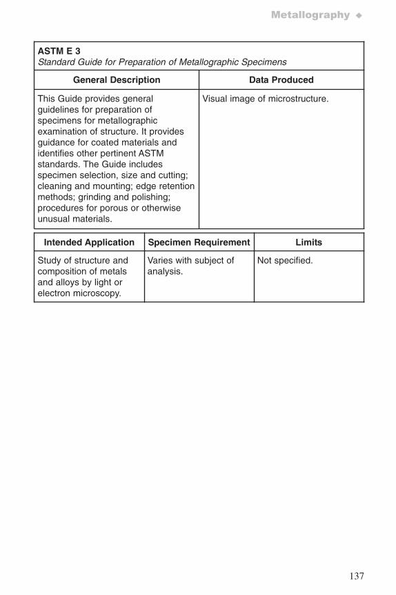
137
Metallography ♦
ASTM E 3Standard Guide for Preparation of Metallographic Specimens
General Description Data Produced
This Guide provides generalguidelines for preparation ofspecimens for metallographicexamination of structure. It providesguidance for coated materials andidentifies other pertinent ASTMstandards. The Guide includesspecimen selection, size and cutting;cleaning and mounting; edge retentionmethods; grinding and polishing;procedures for porous or otherwiseunusual materials.
Visual image of microstructure.
Intended Application Specimen Requirement Limits
Study of structure andcomposition of metalsand alloys by light orelectron microscopy.
Varies with subject ofanalysis.
Not specified.
7652_.qxd 9/27/2005 11:58 AM Page 137
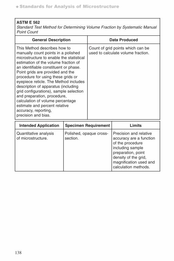
138
♦Standards for Analysis of Microstructure
ASTM E 562Standard Test Method for Determining Volume Fraction by Systematic ManualPoint Count
General Description Data Produced
This Method describes how tomanually count points in a polishedmicrostructure to enable the statisticalestimation of the volume fraction ofan identifiable constituent or phase.Point grids are provided and theprocedure for using these grids oreyepiece reticle. The Method includesdescription of apparatus (includinggrid configurations), sample selectionand preparation, procedure,calculation of volume percentageestimate and percent relativeaccuracy, reporting,precision and bias.
Count of grid points which can beused to calculate volume fraction.
Intended Application Specimen Requirement Limits
Quantitative analysisof microstructure.
Polished, opaque cross-section.
Precision and relativeaccuracy are a functionof the procedureincluding samplepreparation, pointdensity of the grid,magnification used andcalculation methods.
7652_.qxd 9/27/2005 11:58 AM Page 138
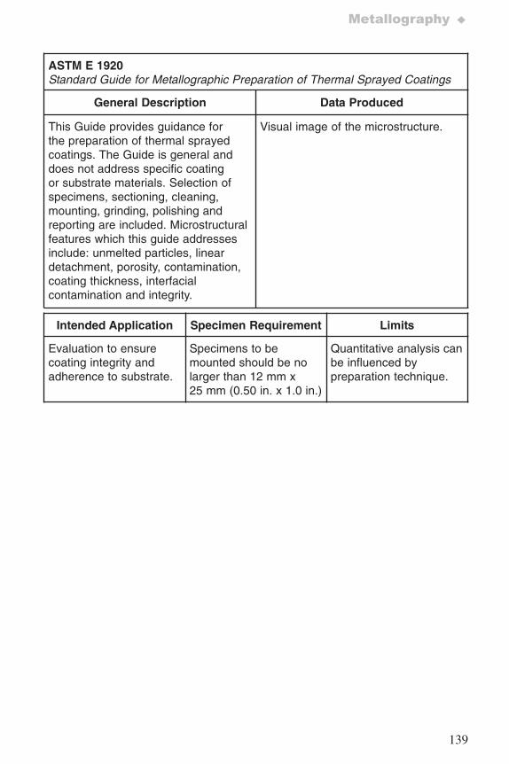
139
Metallography ♦
ASTM E 1920Standard Guide for Metallographic Preparation of Thermal Sprayed Coatings
General Description Data Produced
This Guide provides guidance forthe preparation of thermal sprayedcoatings. The Guide is general anddoes not address specific coatingor substrate materials. Selection ofspecimens, sectioning, cleaning,mounting, grinding, polishing andreporting are included. Microstructuralfeatures which this guide addressesinclude: unmelted particles, lineardetachment, porosity, contamination,coating thickness, interfacialcontamination and integrity.
Visual image of the microstructure.
Intended Application Specimen Requirement Limits
Evaluation to ensurecoating integrity andadherence to substrate.
Specimens to bemounted should be nolarger than 12 mm x25 mm (0.50 in. x 1.0 in.)
Quantitative analysis canbe influenced bypreparation technique.
7652_.qxd 9/27/2005 11:58 AM Page 139
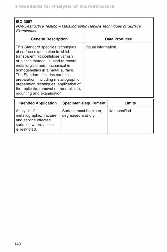
140
♦Standards for Analysis of Microstructure
ISO 3057Non-Destructive Testing – Metallographic Replica Techniques of SurfaceExamination
General Description Data Produced
This Standard specifies techniquesof surface examination in whichtransparent nitrocellulose varnishor plastic material is used to recordmetallurgical and mechanical inhomogeneities in a metal surface.The Standard includes surfacepreparation, including metallographicpreparation techniques, application ofthe replicate, removal of the replicate,mounting and examination.
Visual information.
Intended Application Specimen Requirement Limits
Analysis ofmetallographic, fractureand service effectedsurfaces where accessis restricted.
Surface must be clean,degreased and dry.
Not specified.
7652_.qxd 9/27/2005 11:58 AM Page 140
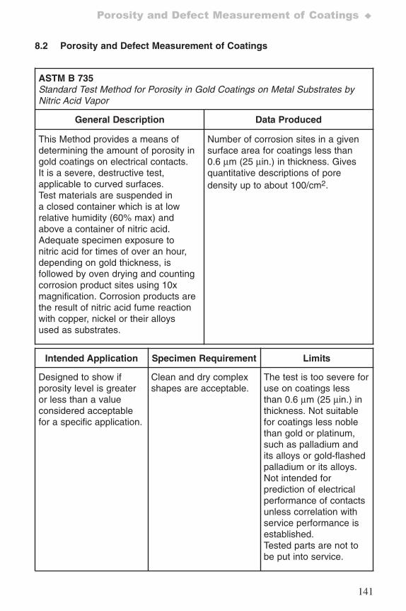
141
Porosity and Defect Measurement of Coatings ♦
8.2 Porosity and Defect Measurement of Coatings
ASTM B 735Standard Test Method for Porosity in Gold Coatings on Metal Substrates byNitric Acid Vapor
General Description Data Produced
This Method provides a means ofdetermining the amount of porosity ingold coatings on electrical contacts.It is a severe, destructive test,applicable to curved surfaces.Test materials are suspended ina closed container which is at lowrelative humidity (60% max) andabove a container of nitric acid.Adequate specimen exposure tonitric acid for times of over an hour,depending on gold thickness, isfollowed by oven drying and countingcorrosion product sites using 10xmagnification. Corrosion products arethe result of nitric acid fume reactionwith copper, nickel or their alloysused as substrates.
Number of corrosion sites in a givensurface area for coatings less than0.6 μm (25 μin.) in thickness. Givesquantitative descriptions of poredensity up to about 100/cm2.
Intended Application Specimen Requirement Limits
Designed to show ifporosity level is greateror less than a valueconsidered acceptablefor a specific application.
Clean and dry complexshapes are acceptable.
The test is too severe foruse on coatings lessthan 0.6 μm (25 μin.) inthickness. Not suitablefor coatings less noblethan gold or platinum,such as palladium andits alloys or gold-flashedpalladium or its alloys.Not intended forprediction of electricalperformance of contactsunless correlation withservice performance isestablished.Tested parts are not tobe put into service.
7652_.qxd 9/27/2005 11:58 AM Page 141
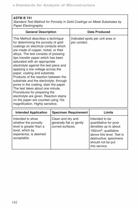
142
♦Standards for Analysis of Microstructure
ASTM B 741Standard Test Method for Porosity in Gold Coatings on Metal Substrates byPaper Electrography
General Description Data Produced
This Method describes a techniquefor determining the porosity of goldcoatings on electrical contacts whichare made of copper, nickel, or theiralloys. The test consists of pressingdye transfer paper which has beensaturated with an appropriateelectrolyte against the test piece andapplying a low voltage across thepaper, coating and substrate.Products of the reaction between thesubstrate and the electrolyte, throughpores in the coating, stain the paper.The test takes about one minute.Procedures for preparing theelectrolyte are given. Reaction stainson the paper are counted using 10xmagnification. Highly sensitive.
Indicated spots per unit area orper contact.
Intended Application Specimen Requirement Limits
Intended to showwhether the porositylevel is greater than alevel, which byexperience, is deemedacceptable.
Clean and dry andgenerally flat or gentlycurved surfaces.
Intended to bequantitative for poredensities up to about100/cm2; qualitativeabove this level. Test isdestructive; specimensshould not be putinto service.
7652_.qxd 9/27/2005 11:58 AM Page 142
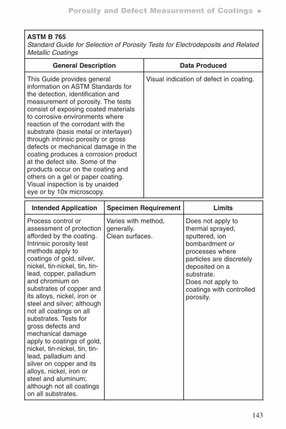
143
Porosity and Defect Measurement of Coatings ♦
ASTM B 765 Standard Guide for Selection of Porosity Tests for Electrodeposits and RelatedMetallic Coatings
General Description Data Produced
This Guide provides generalinformation on ASTM Standards forthe detection, identification andmeasurement of porosity. The testsconsist of exposing coated materialsto corrosive environments wherereaction of the corrodant with thesubstrate (basis metal or interlayer)through intrinsic porosity or grossdefects or mechanical damage in thecoating produces a corrosion productat the defect site. Some of theproducts occur on the coating andothers on a gel or paper coating.Visual inspection is by unaidedeye or by 10x microscopy.
Visual indication of defect in coating.
Intended Application Specimen Requirement Limits
Process control orassessment of protectionafforded by the coating.Intrinsic porosity testmethods apply tocoatings of gold, silver,nickel, tin-nickel, tin, tin-lead, copper, palladiumand chromium onsubstrates of copper andits alloys, nickel, iron orsteel and silver; althoughnot all coatings on allsubstrates. Tests forgross defects andmechanical damageapply to coatings of gold,nickel, tin-nickel, tin, tin-lead, palladium andsilver on copper and itsalloys, nickel, iron orsteel and aluminum;although not all coatingson all substrates.
Varies with method,generally.Clean surfaces.
Does not apply tothermal sprayed,sputtered, ionbombardment orprocesses whereparticles are discretelydeposited on asubstrate.Does not apply tocoatings with controlledporosity.
7652_.qxd 9/27/2005 11:58 AM Page 143
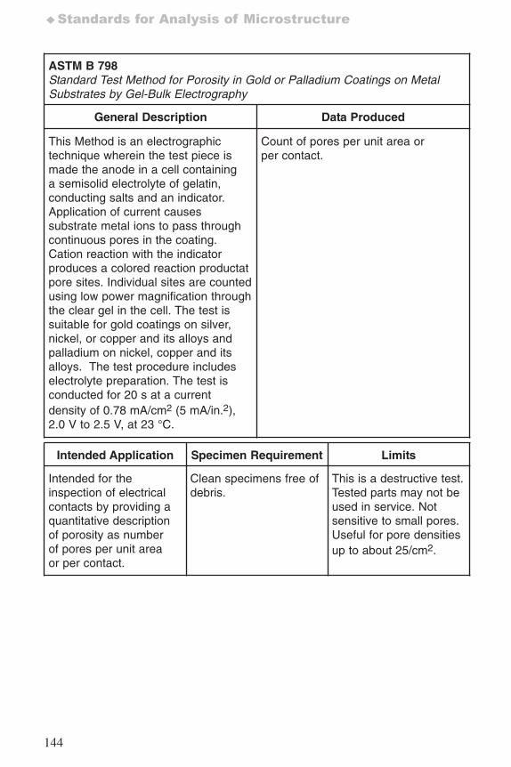
144
♦Standards for Analysis of Microstructure
ASTM B 798Standard Test Method for Porosity in Gold or Palladium Coatings on MetalSubstrates by Gel-Bulk Electrography
General Description Data Produced
This Method is an electrographictechnique wherein the test piece ismade the anode in a cell containinga semisolid electrolyte of gelatin,conducting salts and an indicator.Application of current causessubstrate metal ions to pass throughcontinuous pores in the coating.Cation reaction with the indicatorproduces a colored reaction productatpore sites. Individual sites are countedusing low power magnification throughthe clear gel in the cell. The test issuitable for gold coatings on silver,nickel, or copper and its alloys andpalladium on nickel, copper and itsalloys. The test procedure includeselectrolyte preparation. The test isconducted for 20 s at a currentdensity of 0.78 mA/cm2 (5 mA/in.2),2.0 V to 2.5 V, at 23 °C.
Count of pores per unit area orper contact.
Intended Application Specimen Requirement Limits
Intended for theinspection of electricalcontacts by providing aquantitative descriptionof porosity as numberof pores per unit areaor per contact.
Clean specimens free ofdebris.
This is a destructive test.Tested parts may not beused in service. Notsensitive to small pores.Useful for pore densitiesup to about 25/cm2.
7652_.qxd 9/27/2005 11:58 AM Page 144
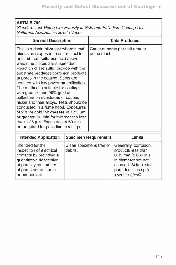
145
Porosity and Defect Measurement of Coatings ♦
ASTM B 799Standard Test Method for Porosity in Gold and Palladium Coatings bySulfurous Acid/Sulfur-Dioxide Vapor
General Description Data Produced
This is a destructive test wherein testpieces are exposed to sulfur dioxideemitted from sulfurous acid abovewhich the pieces are suspended.Reaction of the sulfur dioxide with thesubstrate produces corrosion productsat pores in the coating. Spots arecounted with low power magnification.The method is suitable for coatingswith greater than 95% gold orpalladium on substrates of copper,nickel and their alloys. Tests should beconducted in a fume hood. Exposuresof 2 h for gold thicknesses of 1.25 μmor greater; 90 min for thicknesses lessthan 1.25 μm. Exposures of 60 minare required for palladium coatings.
Count of pores per unit area orper contact.
Intended Application Specimen Requirement Limits
Intended for theinspection of electricalcontacts by providing aquantitative descriptionof porosity as numberof pores per unit areaor per contact.
Clean specimens free ofdebris.
Generally, corrosionproducts less than0.05 mm (0.002 in.)in diameter are notcounted. Suitable forpore densities up toabout 100/cm2.
7652_.qxd 9/27/2005 11:58 AM Page 145
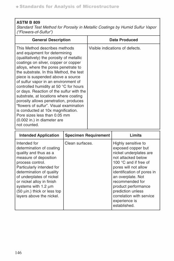
146
♦Standards for Analysis of Microstructure
ASTM B 809Standard Test Method for Porosity in Metallic Coatings by Humid Sulfur Vapor(“Flowers-of-Sulfur”)
General Description Data Produced
This Method describes methodsand equipment for determining(qualitatively) the porosity of metalliccoatings on silver, copper or copperalloys, where the pores penetrate tothe substrate. In this Method, the testpiece is suspended above a sourceof sulfur vapor in an environment ofcontrolled humidity at 50 °C for hoursor days. Reaction of the sulfur with thesubstrate, at locations where coatingporosity allows penetration, produces“flowers of sulfur”. Visual examinationis conducted at 10x magnification.Pore sizes less than 0.05 mm(0.002 in.) in diameter arenot counted.
Visible indications of defects.
Intended Application Specimen Requirement Limits
Intended fordetermination of coatingquality and thus as ameasure of depositionprocess control.Particularly intended fordetermination of qualityof underplates of nickelor nickel alloy in finishsystems with 1.2 μm(50 μin.) thick or less toplayers above the nickel.
Clean surfaces. Highly sensitive toexposed copper butnickel underplates arenot attacked below100 °C and if free ofpores will not allowidentification of pores inan overplate. Notrecommended forproduct performanceprediction unlesscorrelation with serviceexperience isestablished.
7652_.qxd 9/27/2005 11:58 AM Page 146
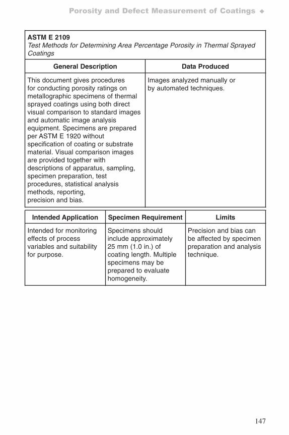
147
Porosity and Defect Measurement of Coatings ♦
ASTM E 2109Test Methods for Determining Area Percentage Porosity in Thermal SprayedCoatings
General Description Data Produced
This document gives proceduresfor conducting porosity ratings onmetallographic specimens of thermalsprayed coatings using both directvisual comparison to standard imagesand automatic image analysisequipment. Specimens are preparedper ASTM E 1920 withoutspecification of coating or substratematerial. Visual comparison imagesare provided together withdescriptions of apparatus, sampling,specimen preparation, testprocedures, statistical analysismethods, reporting,precision and bias.
Images analyzed manually orby automated techniques.
Intended Application Specimen Requirement Limits
Intended for monitoringeffects of processvariables and suitabilityfor purpose.
Specimens shouldinclude approximately25 mm (1.0 in.) ofcoating length. Multiplespecimens may beprepared to evaluatehomogeneity.
Precision and bias canbe affected by specimenpreparation and analysistechnique.
7652_.qxd 9/27/2005 11:58 AM Page 147
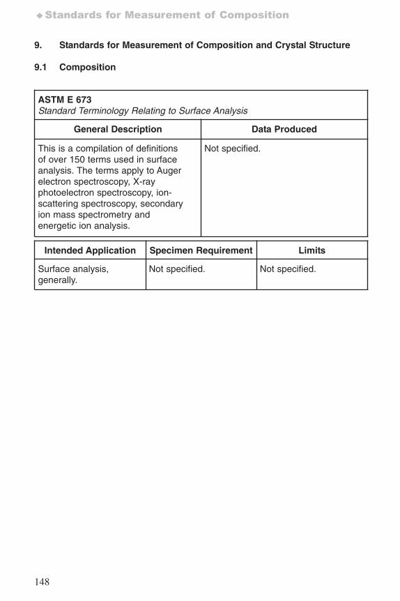
148
♦Standards for Measurement of Composition
9. Standards for Measurement of Composition and Crystal Structure
9.1 Composition
ASTM E 673Standard Terminology Relating to Surface Analysis
General Description Data Produced
This is a compilation of definitionsof over 150 terms used in surfaceanalysis. The terms apply to Augerelectron spectroscopy, X-rayphotoelectron spectroscopy, ion-scattering spectroscopy, secondaryion mass spectrometry andenergetic ion analysis.
Not specified.
Intended Application Specimen Requirement Limits
Surface analysis,generally.
Not specified. Not specified.
7652_.qxd 9/27/2005 11:58 AM Page 148
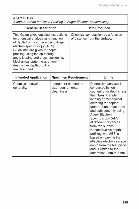
149
Composition ♦
ASTM E 1127Standard Guide for Depth Profiling in Auger Electron Spectroscopy
General Description Data Produced
This Guide gives detailed instructionsfor chemical analysis as a functionof depth from a surface using Augerelectron spectroscopy (AES).Guidelines are given for depthprofiling using ion sputtering,angle lapping and cross-sectioning.Mechanical cratering and non-destructive depth profilingare described.
Chemical composition as a functionof distance from the surface.
Intended Application Specimen Requirement Limits
Chemical analysisgenerally.
Instrument dependentsize requirements, cleanliness.
Destructive analysis isconducted by ionsputtering for depths lessthan 1μm or anglelapping or mechanicalcratering for depthsgreater than about 1 μmand subsequently usingAuger ElectronSpectroscopy (AES)at different distancesfrom the surface.Nondestructive depthprofiling with AES isbased on varying theeffective electron escapedepth from the test pieceand is limited to theoutermost 2 nm to 5 nm.
7652_.qxd 9/27/2005 11:58 AM Page 149
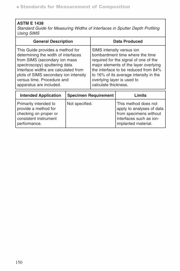
150
♦Standards for Measurement of Composition
ASTM E 1438Standard Guide for Measuring Widths of Interfaces in Sputter Depth ProfilingUsing SIMS
General Description Data Produced
This Guide provides a method fordetermining the width of interfacesfrom SIMS (secondary ion massspectroscopy) sputtering data.Interface widths are calculated fromplots of SIMS secondary ion intensityversus time. Procedure andapparatus are included.
SIMS intensity versus ionbombardment time where the timerequired for the signal of one of themajor elements of the layer overlyingthe interface to be reduced from 84%to 16% of its average intensity in theoverlying layer is used tocalculate thickness.
Intended Application Specimen Requirement Limits
Primarily intended toprovide a method forchecking on proper orconsistent instrumentperformance.
Not specified. This method does notapply to analyses of datafrom specimens withoutinterfaces such as ion-implanted material.
7652_.qxd 9/27/2005 11:58 AM Page 150
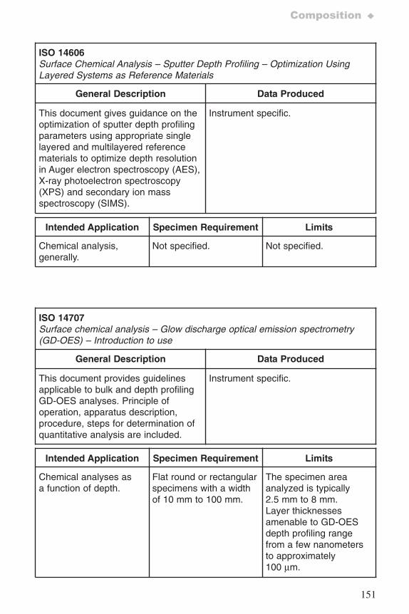
151
Composition ♦
ISO 14606Surface Chemical Analysis – Sputter Depth Profiling – Optimization UsingLayered Systems as Reference Materials
General Description Data Produced
This document gives guidance on theoptimization of sputter depth profilingparameters using appropriate singlelayered and multilayered referencematerials to optimize depth resolutionin Auger electron spectroscopy (AES),X-ray photoelectron spectroscopy(XPS) and secondary ion massspectroscopy (SIMS).
Instrument specific.
Intended Application Specimen Requirement Limits
Chemical analysis,generally.
Not specified. Not specified.
ISO 14707Surface chemical analysis – Glow discharge optical emission spectrometry(GD-OES) – Introduction to use
General Description Data Produced
This document provides guidelinesapplicable to bulk and depth profilingGD-OES analyses. Principle ofoperation, apparatus description,procedure, steps for determination ofquantitative analysis are included.
Instrument specific.
Intended Application Specimen Requirement Limits
Chemical analyses asa function of depth.
Flat round or rectangularspecimens with a widthof 10 mm to 100 mm.
The specimen areaanalyzed is typically2.5 mm to 8 mm.Layer thicknessesamenable to GD-OESdepth profiling rangefrom a few nanometersto approximately100 μm.
7652_.qxd 9/27/2005 11:58 AM Page 151
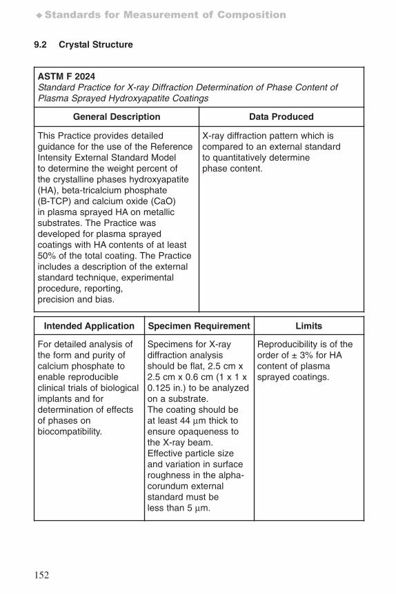
152
♦Standards for Measurement of Composition
9.2 Crystal Structure
ASTM F 2024Standard Practice for X-ray Diffraction Determination of Phase Content ofPlasma Sprayed Hydroxyapatite Coatings
General Description Data Produced
This Practice provides detailedguidance for the use of the ReferenceIntensity External Standard Modelto determine the weight percent ofthe crystalline phases hydroxyapatite(HA), beta-tricalcium phosphate(B-TCP) and calcium oxide (CaO)in plasma sprayed HA on metallicsubstrates. The Practice wasdeveloped for plasma sprayedcoatings with HA contents of at least50% of the total coating. The Practiceincludes a description of the externalstandard technique, experimentalprocedure, reporting,precision and bias.
X-ray diffraction pattern which iscompared to an external standardto quantitatively determinephase content.
Intended Application Specimen Requirement Limits
For detailed analysis ofthe form and purity ofcalcium phosphate toenable reproducibleclinical trials of biologicalimplants and fordetermination of effectsof phases onbiocompatibility.
Specimens for X-raydiffraction analysisshould be flat, 2.5 cm x2.5 cm x 0.6 cm (1 x 1 x0.125 in.) to be analyzedon a substrate.The coating should beat least 44 μm thick toensure opaqueness tothe X-ray beam.Effective particle sizeand variation in surfaceroughness in the alpha-corundum externalstandard must beless than 5 μm.
Reproducibility is of theorder of ± 3% for HAcontent of plasmasprayed coatings.
7652_.qxd 9/27/2005 11:58 AM Page 152
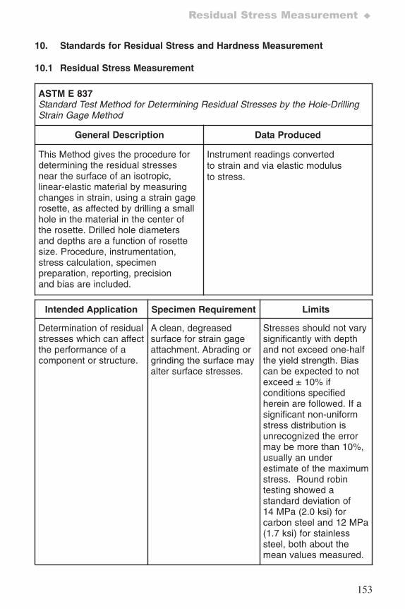
153
Residual Stress Measurement ♦
10. Standards for Residual Stress and Hardness Measurement
10.1 Residual Stress Measurement
ASTM E 837Standard Test Method for Determining Residual Stresses by the Hole-DrillingStrain Gage Method
General Description Data Produced
This Method gives the procedure fordetermining the residual stressesnear the surface of an isotropic,linear-elastic material by measuringchanges in strain, using a strain gagerosette, as affected by drilling a smallhole in the material in the center ofthe rosette. Drilled hole diametersand depths are a function of rosettesize. Procedure, instrumentation,stress calculation, specimenpreparation, reporting, precisionand bias are included.
Instrument readings convertedto strain and via elastic modulusto stress.
Intended Application Specimen Requirement Limits
Determination of residualstresses which can affectthe performance of acomponent or structure.
A clean, degreasedsurface for strain gageattachment. Abrading orgrinding the surface mayalter surface stresses.
Stresses should not varysignificantly with depthand not exceed one-halfthe yield strength. Biascan be expected to notexceed ± 10% ifconditions specifiedherein are followed. If asignificant non-uniformstress distribution isunrecognized the errormay be more than 10%,usually an underestimate of the maximumstress. Round robintesting showed astandard deviation of14 MPa (2.0 ksi) forcarbon steel and 12 MPa(1.7 ksi) for stainlesssteel, both about themean values measured.
7652_.qxd 9/27/2005 11:58 AM Page 153
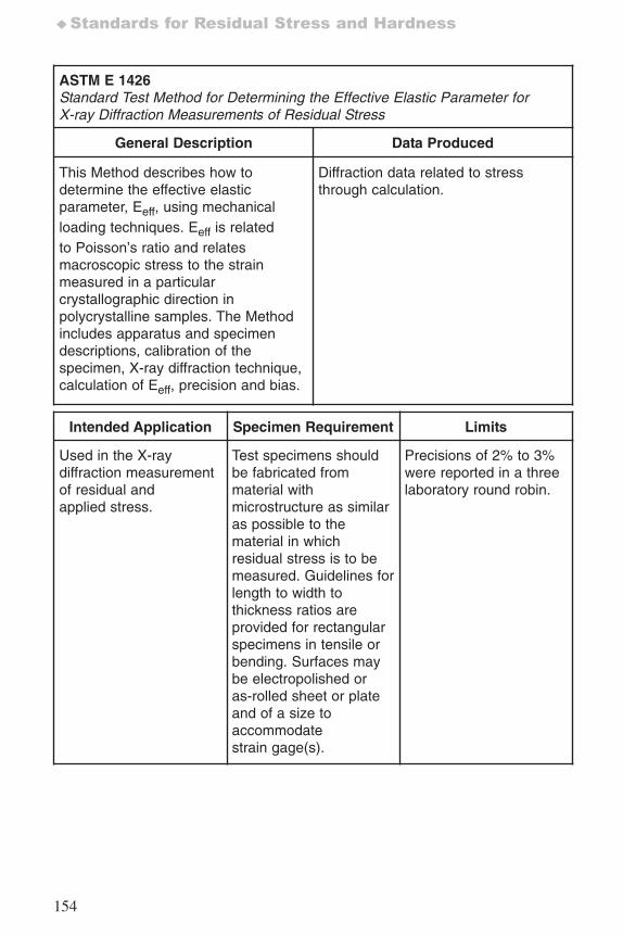
154
♦Standards for Residual Stress and Hardness
ASTM E 1426Standard Test Method for Determining the Effective Elastic Parameter forX-ray Diffraction Measurements of Residual Stress
General Description Data Produced
This Method describes how todetermine the effective elasticparameter, Eeff, using mechanicalloading techniques. Eeff is relatedto Poisson’s ratio and relatesmacroscopic stress to the strainmeasured in a particularcrystallographic direction inpolycrystalline samples. The Methodincludes apparatus and specimendescriptions, calibration of thespecimen, X-ray diffraction technique,calculation of Eeff, precision and bias.
Diffraction data related to stressthrough calculation.
Intended Application Specimen Requirement Limits
Used in the X-raydiffraction measurementof residual andapplied stress.
Test specimens shouldbe fabricated frommaterial withmicrostructure as similaras possible to thematerial in whichresidual stress is to bemeasured. Guidelines forlength to width tothickness ratios areprovided for rectangularspecimens in tensile orbending. Surfaces maybe electropolished oras-rolled sheet or plateand of a size toaccommodatestrain gage(s).
Precisions of 2% to 3%were reported in a threelaboratory round robin.
7652_.qxd 9/27/2005 11:58 AM Page 154
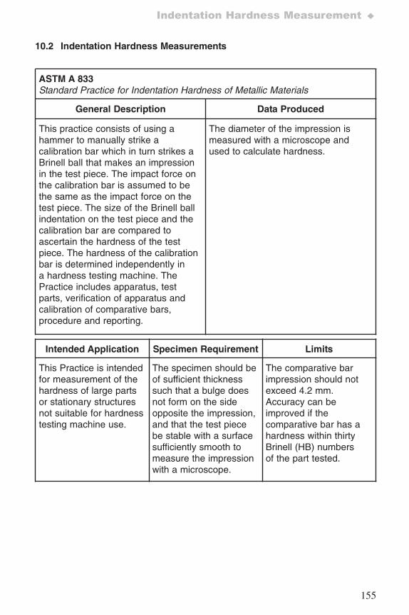
155
Indentation Hardness Measurement ♦
10.2 Indentation Hardness Measurements
ASTM A 833Standard Practice for Indentation Hardness of Metallic Materials
General Description Data Produced
This practice consists of using ahammer to manually strike acalibration bar which in turn strikes aBrinell ball that makes an impressionin the test piece. The impact force onthe calibration bar is assumed to bethe same as the impact force on thetest piece. The size of the Brinell ballindentation on the test piece and thecalibration bar are compared toascertain the hardness of the testpiece. The hardness of the calibrationbar is determined independently ina hardness testing machine. ThePractice includes apparatus, testparts, verification of apparatus andcalibration of comparative bars,procedure and reporting.
The diameter of the impression ismeasured with a microscope andused to calculate hardness.
Intended Application Specimen Requirement Limits
This Practice is intendedfor measurement of thehardness of large partsor stationary structuresnot suitable for hardnesstesting machine use.
The specimen should beof sufficient thicknesssuch that a bulge doesnot form on the sideopposite the impression,and that the test piecebe stable with a surfacesufficiently smooth tomeasure the impressionwith a microscope.
The comparative barimpression should notexceed 4.2 mm.Accuracy can beimproved if thecomparative bar has ahardness within thirtyBrinell (HB) numbersof the part tested.
7652_.qxd 9/27/2005 11:58 AM Page 155
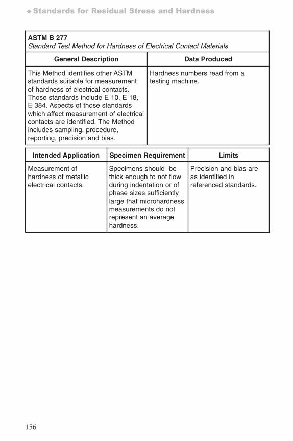
156
♦Standards for Residual Stress and Hardness
ASTM B 277 Standard Test Method for Hardness of Electrical Contact Materials
General Description Data Produced
This Method identifies other ASTMstandards suitable for measurementof hardness of electrical contacts.Those standards include E 10, E 18,E 384. Aspects of those standardswhich affect measurement of electricalcontacts are identified. The Methodincludes sampling, procedure,reporting, precision and bias.
Hardness numbers read from atesting machine.
Intended Application Specimen Requirement Limits
Measurement ofhardness of metallicelectrical contacts.
Specimens should bethick enough to not flowduring indentation or ofphase sizes sufficientlylarge that microhardnessmeasurements do notrepresent an averagehardness.
Precision and bias areas identified inreferenced standards.
7652_.qxd 9/27/2005 11:58 AM Page 156
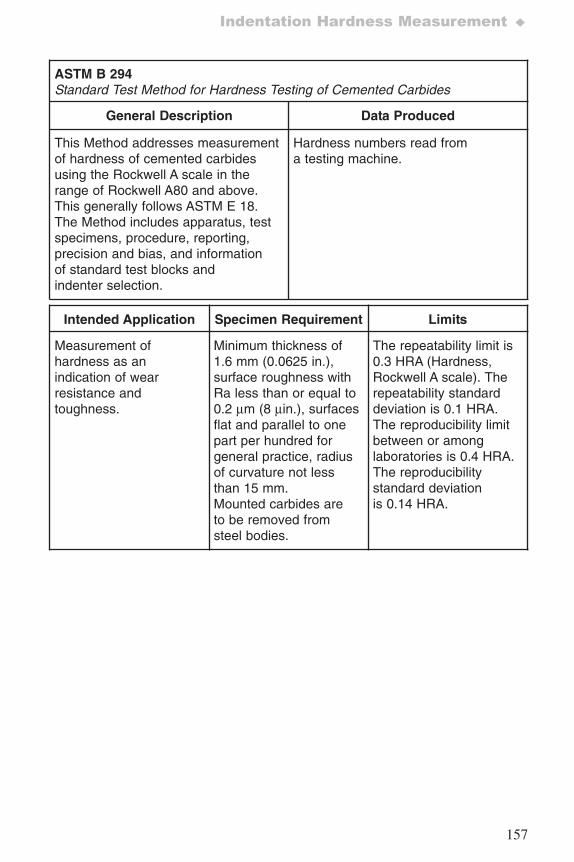
157
Indentation Hardness Measurement ♦
ASTM B 294Standard Test Method for Hardness Testing of Cemented Carbides
General Description Data Produced
This Method addresses measurementof hardness of cemented carbidesusing the Rockwell A scale in therange of Rockwell A80 and above.This generally follows ASTM E 18.The Method includes apparatus, testspecimens, procedure, reporting,precision and bias, and informationof standard test blocks andindenter selection.
Hardness numbers read froma testing machine.
Intended Application Specimen Requirement Limits
Measurement ofhardness as anindication of wearresistance andtoughness.
Minimum thickness of1.6 mm (0.0625 in.),surface roughness withRa less than or equal to0.2 μm (8 μin.), surfacesflat and parallel to onepart per hundred forgeneral practice, radiusof curvature not lessthan 15 mm.Mounted carbides areto be removed fromsteel bodies.
The repeatability limit is0.3 HRA (Hardness,Rockwell A scale). Therepeatability standarddeviation is 0.1 HRA.The reproducibility limitbetween or amonglaboratories is 0.4 HRA.The reproducibilitystandard deviationis 0.14 HRA.
7652_.qxd 9/27/2005 11:58 AM Page 157
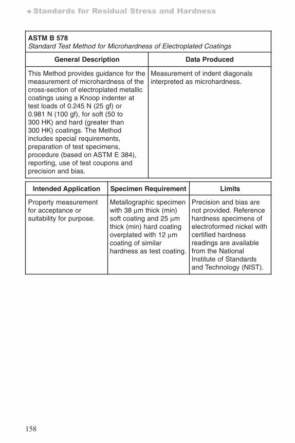
158
♦Standards for Residual Stress and Hardness
ASTM B 578Standard Test Method for Microhardness of Electroplated Coatings
General Description Data Produced
This Method provides guidance for themeasurement of microhardness of thecross-section of electroplated metalliccoatings using a Knoop indenter attest loads of 0.245 N (25 gf) or0.981 N (100 gf), for soft (50 to300 HK) and hard (greater than300 HK) coatings. The Methodincludes special requirements,preparation of test specimens,procedure (based on ASTM E 384),reporting, use of test coupons andprecision and bias.
Measurement of indent diagonalsinterpreted as microhardness.
Intended Application Specimen Requirement Limits
Property measurementfor acceptance orsuitability for purpose.
Metallographic specimenwith 38 μm thick (min)soft coating and 25 μmthick (min) hard coatingoverplated with 12 μmcoating of similarhardness as test coating.
Precision and bias arenot provided. Referencehardness specimens ofelectroformed nickel withcertified hardnessreadings are availablefrom the NationalInstitute of Standardsand Technology (NIST).
7652_.qxd 9/27/2005 11:58 AM Page 158
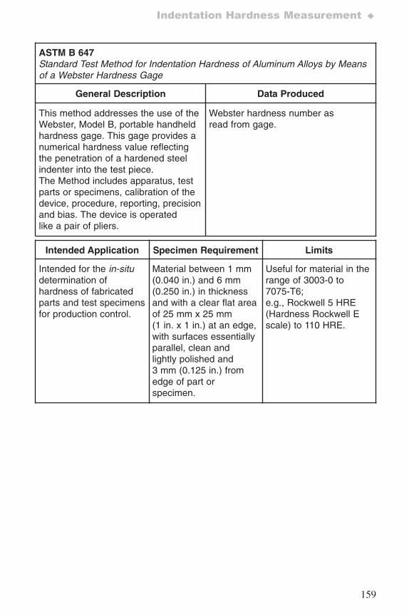
159
Indentation Hardness Measurement ♦
ASTM B 647Standard Test Method for Indentation Hardness of Aluminum Alloys by Meansof a Webster Hardness Gage
General Description Data Produced
This method addresses the use of theWebster, Model B, portable handheldhardness gage. This gage provides anumerical hardness value reflectingthe penetration of a hardened steelindenter into the test piece.The Method includes apparatus, testparts or specimens, calibration of thedevice, procedure, reporting, precisionand bias. The device is operatedlike a pair of pliers.
Webster hardness number asread from gage.
Intended Application Specimen Requirement Limits
Intended for the in-situdetermination ofhardness of fabricatedparts and test specimensfor production control.
Material between 1 mm(0.040 in.) and 6 mm(0.250 in.) in thicknessand with a clear flat areaof 25 mm x 25 mm(1 in. x 1 in.) at an edge,with surfaces essentiallyparallel, clean andlightly polished and3 mm (0.125 in.) fromedge of part orspecimen.
Useful for material in therange of 3003-0 to7075-T6;e.g., Rockwell 5 HRE(Hardness Rockwell Escale) to 110 HRE.
7652_.qxd 9/27/2005 11:58 AM Page 159
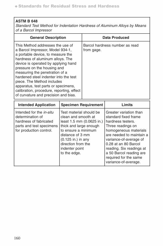
160
♦Standards for Residual Stress and Hardness
ASTM B 648Standard Test Method for Indentation Hardness of Aluminum Alloys by Meansof a Barcol Impressor
General Description Data Produced
This Method addresses the use ofa Barcol Impressor, Model 934-1,a portable device, to measure thehardness of aluminum alloys. Thedevice is operated by applying handpressure on the housing andmeasuring the penetration of ahardened steel indenter into the testpiece. The Method includesapparatus, test parts or specimens,calibration, procedure, reporting, effectof curvature and precision and bias.
Barcol hardness number as readfrom gage.
Intended Application Specimen Requirement Limits
Intended for the in-situdetermination ofhardness of fabricatedparts and test specimensfor production control.
Test material should beclean and smooth atleast 1.5 mm (0.0625 in.)thick and large enoughto ensure a minimumdistance of 3 mm(0.125 in.) in anydirection from theindenter pointto the edge.
Greater variation thanstandard fixed framehardness testers.Three readings onhomogeneous materialsare needed to maintain avariance-of-average of0.28 at an 80 Barcolreading. Six readings ata 50 Barcol reading arerequired for the samevariance-of-average.
7652_.qxd 9/27/2005 11:58 AM Page 160
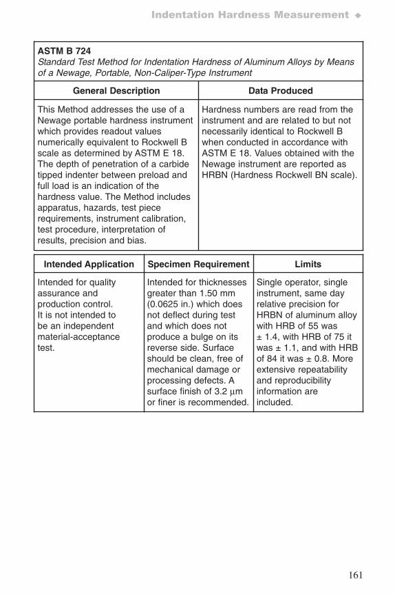
161
Indentation Hardness Measurement ♦
ASTM B 724Standard Test Method for Indentation Hardness of Aluminum Alloys by Meansof a Newage, Portable, Non-Caliper-Type Instrument
General Description Data Produced
This Method addresses the use of aNewage portable hardness instrumentwhich provides readout valuesnumerically equivalent to Rockwell Bscale as determined by ASTM E 18.The depth of penetration of a carbidetipped indenter between preload andfull load is an indication of thehardness value. The Method includesapparatus, hazards, test piecerequirements, instrument calibration,test procedure, interpretation ofresults, precision and bias.
Hardness numbers are read from theinstrument and are related to but notnecessarily identical to Rockwell Bwhen conducted in accordance withASTM E 18. Values obtained with theNewage instrument are reported asHRBN (Hardness Rockwell BN scale).
Intended Application Specimen Requirement Limits
Intended for qualityassurance andproduction control.It is not intended tobe an independentmaterial-acceptancetest.
Intended for thicknessesgreater than 1.50 mm(0.0625 in.) which doesnot deflect during testand which does notproduce a bulge on itsreverse side. Surfaceshould be clean, free ofmechanical damage orprocessing defects. Asurface finish of 3.2 μmor finer is recommended.
Single operator, singleinstrument, same dayrelative precision forHRBN of aluminum alloywith HRB of 55 was± 1.4, with HRB of 75 itwas ± 1.1, and with HRBof 84 it was ± 0.8. Moreextensive repeatabilityand reproducibilityinformation areincluded.
7652_.qxd 9/27/2005 11:58 AM Page 161
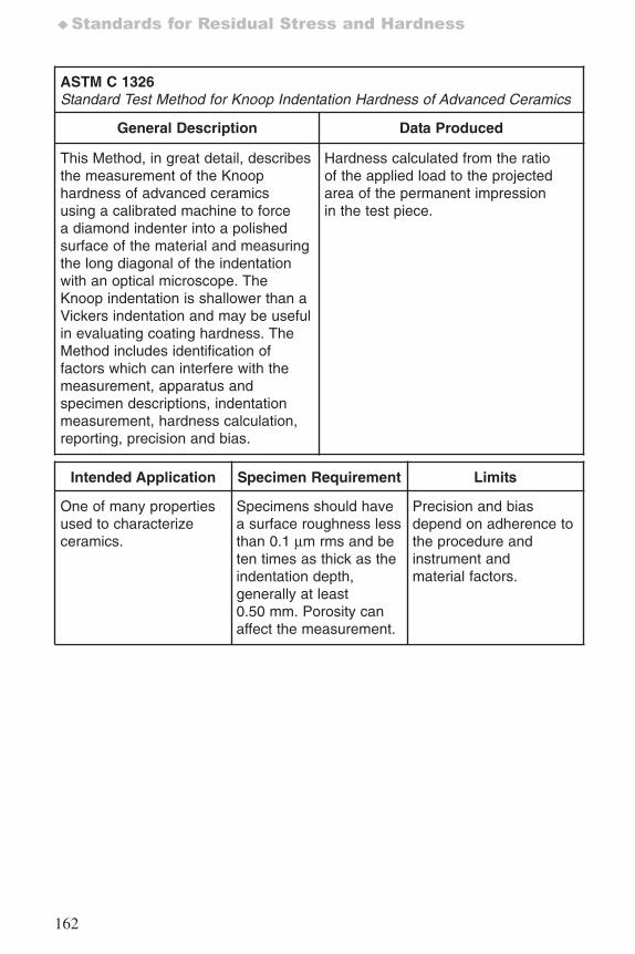
162
♦Standards for Residual Stress and Hardness
ASTM C 1326Standard Test Method for Knoop Indentation Hardness of Advanced Ceramics
General Description Data Produced
This Method, in great detail, describesthe measurement of the Knoophardness of advanced ceramicsusing a calibrated machine to forcea diamond indenter into a polishedsurface of the material and measuringthe long diagonal of the indentationwith an optical microscope. TheKnoop indentation is shallower than aVickers indentation and may be usefulin evaluating coating hardness. TheMethod includes identification offactors which can interfere with themeasurement, apparatus andspecimen descriptions, indentationmeasurement, hardness calculation,reporting, precision and bias.
Hardness calculated from the ratioof the applied load to the projectedarea of the permanent impressionin the test piece.
Intended Application Specimen Requirement Limits
One of many propertiesused to characterizeceramics.
Specimens should havea surface roughness lessthan 0.1 μm rms and beten times as thick as theindentation depth,generally at least0.50 mm. Porosity canaffect the measurement.
Precision and biasdepend on adherence tothe procedure andinstrument andmaterial factors.
7652_.qxd 9/27/2005 11:58 AM Page 162
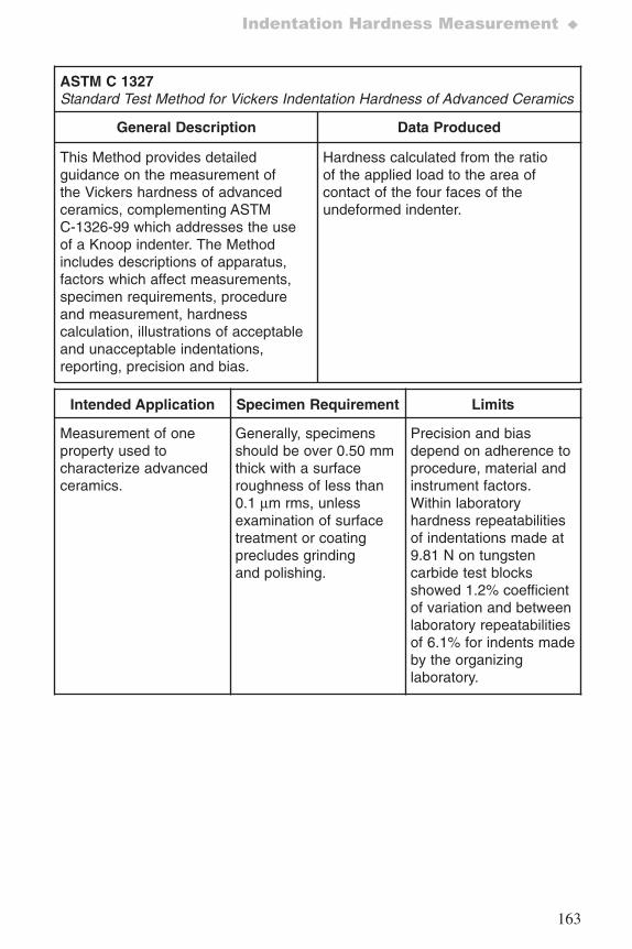
163
Indentation Hardness Measurement ♦
ASTM C 1327Standard Test Method for Vickers Indentation Hardness of Advanced Ceramics
General Description Data Produced
This Method provides detailedguidance on the measurement ofthe Vickers hardness of advancedceramics, complementing ASTMC-1326-99 which addresses the useof a Knoop indenter. The Methodincludes descriptions of apparatus,factors which affect measurements,specimen requirements, procedureand measurement, hardnesscalculation, illustrations of acceptableand unacceptable indentations,reporting, precision and bias.
Hardness calculated from the ratioof the applied load to the area ofcontact of the four faces of theundeformed indenter.
Intended Application Specimen Requirement Limits
Measurement of oneproperty used tocharacterize advancedceramics.
Generally, specimensshould be over 0.50 mmthick with a surfaceroughness of less than0.1 μm rms, unlessexamination of surfacetreatment or coatingprecludes grindingand polishing.
Precision and biasdepend on adherence toprocedure, material andinstrument factors.Within laboratoryhardness repeatabilitiesof indentations made at9.81 N on tungstencarbide test blocksshowed 1.2% coefficientof variation and betweenlaboratory repeatabilitiesof 6.1% for indents madeby the organizinglaboratory.
7652_.qxd 9/27/2005 11:58 AM Page 163
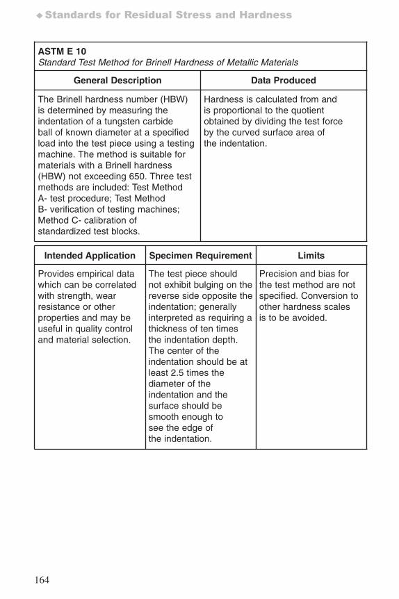
164
♦Standards for Residual Stress and Hardness
ASTM E 10Standard Test Method for Brinell Hardness of Metallic Materials
General Description Data Produced
The Brinell hardness number (HBW)is determined by measuring theindentation of a tungsten carbideball of known diameter at a specifiedload into the test piece using a testingmachine. The method is suitable formaterials with a Brinell hardness(HBW) not exceeding 650. Three testmethods are included: Test MethodA- test procedure; Test MethodB- verification of testing machines;Method C- calibration ofstandardized test blocks.
Hardness is calculated from andis proportional to the quotientobtained by dividing the test forceby the curved surface area ofthe indentation.
Intended Application Specimen Requirement Limits
Provides empirical datawhich can be correlatedwith strength, wearresistance or otherproperties and may beuseful in quality controland material selection.
The test piece shouldnot exhibit bulging on thereverse side opposite theindentation; generallyinterpreted as requiring athickness of ten timesthe indentation depth.The center of theindentation should be atleast 2.5 times thediameter of theindentation and thesurface should besmooth enough tosee the edge ofthe indentation.
Precision and bias forthe test method are notspecified. Conversion toother hardness scalesis to be avoided.
7652_.qxd 9/27/2005 11:58 AM Page 164
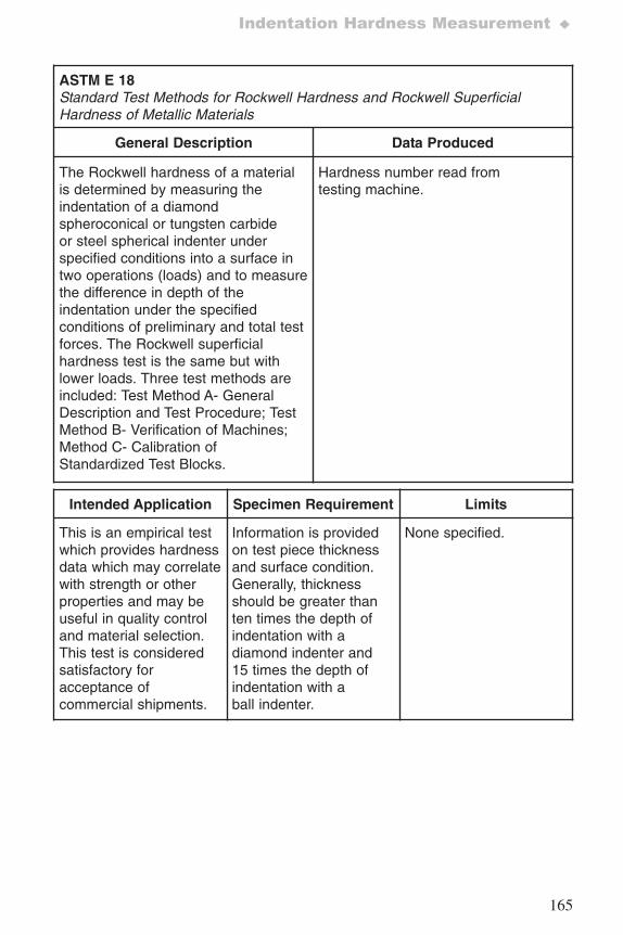
165
Indentation Hardness Measurement ♦
ASTM E 18Standard Test Methods for Rockwell Hardness and Rockwell SuperficialHardness of Metallic Materials
General Description Data Produced
The Rockwell hardness of a materialis determined by measuring theindentation of a diamondspheroconical or tungsten carbideor steel spherical indenter underspecified conditions into a surface intwo operations (loads) and to measurethe difference in depth of theindentation under the specifiedconditions of preliminary and total testforces. The Rockwell superficialhardness test is the same but withlower loads. Three test methods areincluded: Test Method A- GeneralDescription and Test Procedure; TestMethod B- Verification of Machines;Method C- Calibration ofStandardized Test Blocks.
Hardness number read fromtesting machine.
Intended Application Specimen Requirement Limits
This is an empirical testwhich provides hardnessdata which may correlatewith strength or otherproperties and may beuseful in quality controland material selection.This test is consideredsatisfactory foracceptance ofcommercial shipments.
Information is providedon test piece thicknessand surface condition.Generally, thicknessshould be greater thanten times the depth ofindentation with adiamond indenter and15 times the depth ofindentation with aball indenter.
None specified.
7652_.qxd 9/27/2005 11:58 AM Page 165
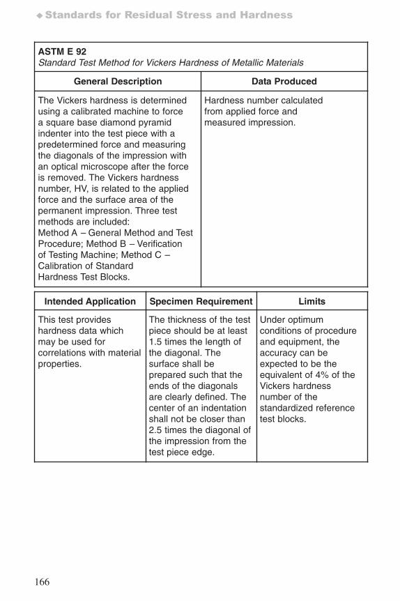
166
♦Standards for Residual Stress and Hardness
ASTM E 92Standard Test Method for Vickers Hardness of Metallic Materials
General Description Data Produced
The Vickers hardness is determinedusing a calibrated machine to forcea square base diamond pyramidindenter into the test piece with apredetermined force and measuringthe diagonals of the impression withan optical microscope after the forceis removed. The Vickers hardnessnumber, HV, is related to the appliedforce and the surface area of thepermanent impression. Three testmethods are included:Method A – General Method and TestProcedure; Method B – Verificationof Testing Machine; Method C –Calibration of StandardHardness Test Blocks.
Hardness number calculatedfrom applied force andmeasured impression.
Intended Application Specimen Requirement Limits
This test provideshardness data whichmay be used forcorrelations with materialproperties.
The thickness of the testpiece should be at least1.5 times the length ofthe diagonal. Thesurface shall beprepared such that theends of the diagonalsare clearly defined. Thecenter of an indentationshall not be closer than2.5 times the diagonal ofthe impression from thetest piece edge.
Under optimumconditions of procedureand equipment, theaccuracy can beexpected to be theequivalent of 4% of theVickers hardnessnumber of thestandardized referencetest blocks.
7652_.qxd 9/27/2005 11:58 AM Page 166
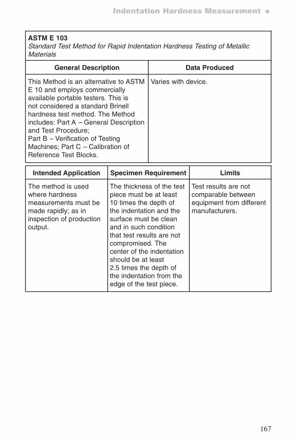
167
Indentation Hardness Measurement ♦
ASTM E 103 Standard Test Method for Rapid Indentation Hardness Testing of MetallicMaterials
General Description Data Produced
This Method is an alternative to ASTME 10 and employs commerciallyavailable portable testers. This isnot considered a standard Brinellhardness test method. The Methodincludes: Part A – General Descriptionand Test Procedure;Part B – Verification of TestingMachines; Part C – Calibration ofReference Test Blocks.
Varies with device.
Intended Application Specimen Requirement Limits
The method is usedwhere hardnessmeasurements must bemade rapidly; as ininspection of productionoutput.
The thickness of the testpiece must be at least10 times the depth ofthe indentation and thesurface must be cleanand in such conditionthat test results are notcompromised. Thecenter of the indentationshould be at least2.5 times the depth ofthe indentation from theedge of the test piece.
Test results are notcomparable betweenequipment from differentmanufacturers.
7652_.qxd 9/27/2005 11:58 AM Page 167
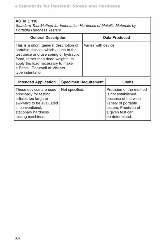
168
♦Standards for Residual Stress and Hardness
ASTM E 110 Standard Test Method for Indentation Hardness of Metallic Materials byPortable Hardness Testers
General Description Data Produced
This is a short, general description ofportable devices which attach to thetest piece and use spring or hydraulicforce, rather than dead weights, toapply the load necessary to makea Brinell, Rockwell or Vickerstype indentation.
Varies with device.
Intended Application Specimen Requirement Limits
These devices are usedprincipally for testingarticles too large orawkward to be evaluatedin conventional,stationary hardnesstesting machines.
Not specified. Precision of the methodis not establishedbecause of the widevariety of portabletesters. Precision ofa given test canbe determined.
7652_.qxd 9/27/2005 11:58 AM Page 168
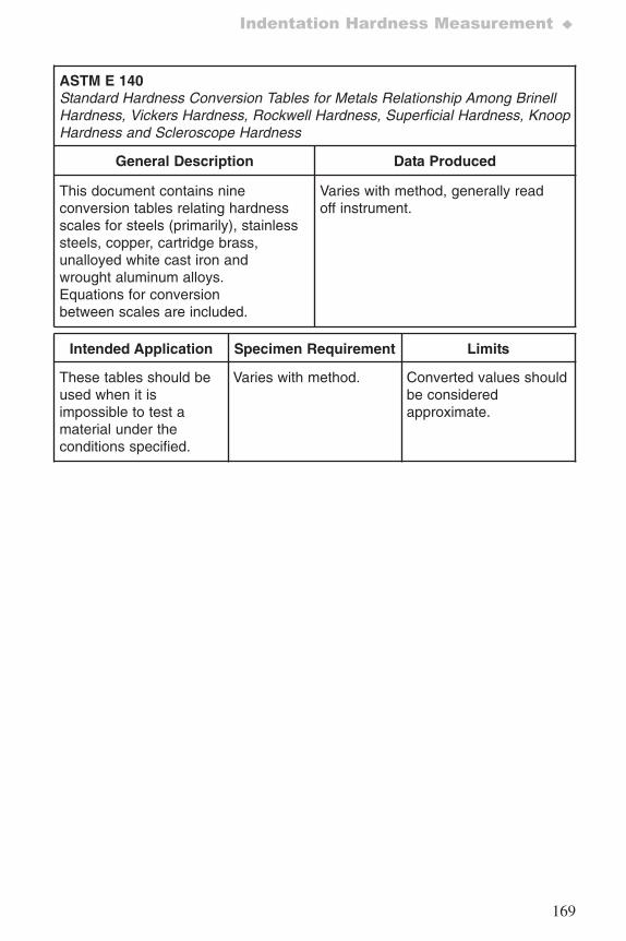
169
Indentation Hardness Measurement ♦
ASTM E 140Standard Hardness Conversion Tables for Metals Relationship Among BrinellHardness, Vickers Hardness, Rockwell Hardness, Superficial Hardness, KnoopHardness and Scleroscope Hardness
General Description Data Produced
This document contains nineconversion tables relating hardnessscales for steels (primarily), stainlesssteels, copper, cartridge brass,unalloyed white cast iron andwrought aluminum alloys.Equations for conversionbetween scales are included.
Varies with method, generally readoff instrument.
Intended Application Specimen Requirement Limits
These tables should beused when it isimpossible to test amaterial under theconditions specified.
Varies with method. Converted values shouldbe consideredapproximate.
7652_.qxd 9/27/2005 11:58 AM Page 169
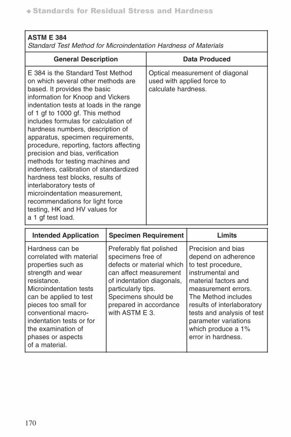
170
♦Standards for Residual Stress and Hardness
ASTM E 384 Standard Test Method for Microindentation Hardness of Materials
General Description Data Produced
E 384 is the Standard Test Methodon which several other methods arebased. It provides the basicinformation for Knoop and Vickersindentation tests at loads in the rangeof 1 gf to 1000 gf. This methodincludes formulas for calculation ofhardness numbers, description ofapparatus, specimen requirements,procedure, reporting, factors affectingprecision and bias, verificationmethods for testing machines andindenters, calibration of standardizedhardness test blocks, results ofinterlaboratory tests ofmicroindentation measurement,recommendations for light forcetesting, HK and HV values fora 1 gf test load.
Optical measurement of diagonalused with applied force tocalculate hardness.
Intended Application Specimen Requirement Limits
Hardness can becorrelated with materialproperties such asstrength and wearresistance.Microindentation testscan be applied to testpieces too small forconventional macro-indentation tests or forthe examination ofphases or aspectsof a material.
Preferably flat polishedspecimens free ofdefects or material whichcan affect measurementof indentation diagonals,particularly tips.Specimens should beprepared in accordancewith ASTM E 3.
Precision and biasdepend on adherenceto test procedure,instrumental andmaterial factors andmeasurement errors.The Method includesresults of interlaboratorytests and analysis of testparameter variationswhich produce a 1%error in hardness.
7652_.qxd 9/27/2005 11:58 AM Page 170
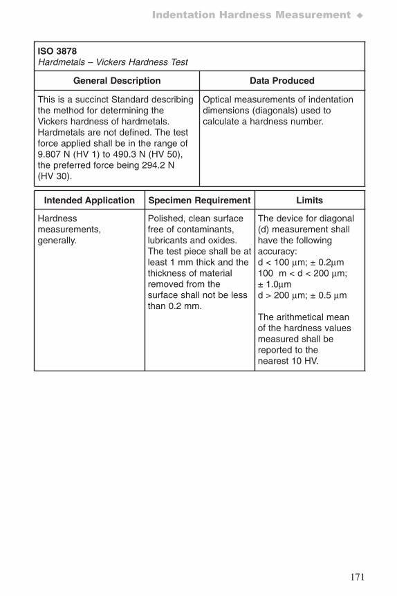
171
Indentation Hardness Measurement ♦
ISO 3878Hardmetals – Vickers Hardness Test
General Description Data Produced
This is a succinct Standard describingthe method for determining theVickers hardness of hardmetals.Hardmetals are not defined. The testforce applied shall be in the range of9.807 N (HV 1) to 490.3 N (HV 50),the preferred force being 294.2 N(HV 30).
Optical measurements of indentationdimensions (diagonals) used tocalculate a hardness number.
Intended Application Specimen Requirement Limits
Hardnessmeasurements,generally.
Polished, clean surfacefree of contaminants,lubricants and oxides.The test piece shall be atleast 1 mm thick and thethickness of materialremoved from thesurface shall not be lessthan 0.2 mm.
The device for diagonal(d) measurement shallhave the followingaccuracy:d < 100 μm; ± 0.2μm100 m < d < 200 μm;± 1.0μmd > 200 μm; ± 0.5 μm
The arithmetical meanof the hardness valuesmeasured shall bereported to thenearest 10 HV.
7652_.qxd 9/27/2005 11:58 AM Page 171
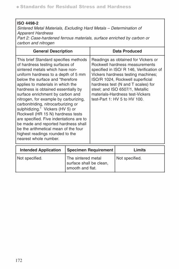
172
♦Standards for Residual Stress and Hardness
ISO 4498-2Sintered Metal Materials, Excluding Hard Metals – Determination ofApparent HardnessPart 2: Case-hardened ferrous materials, surface enriched by carbon orcarbon and nitrogen
General Description Data Produced
This brief Standard specifies methodsof hardness testing surfaces ofsintered metals which have non-uniform hardness to a depth of 5 mmbelow the surface and “thereforeapplies to materials in which thehardness is obtained essentially bysurface enrichment by carbon andnitrogen, for example by carburizing,carbonitriding, nitrocarburizing orsulphidizing.” Vickers (HV 5) orRockwell (HR 15 N) hardness testsare specified. Five indentations are tobe made and reported hardness shallbe the arithmetical mean of the fourhighest readings rounded to thenearest whole number.
Readings as obtained for Vickers orRockwell hardness measurementsspecified in ISO/ R 146, Verification ofVickers hardness testing machines;ISO/R 1024, Rockwell superficialhardness test (N and T scales) forsteel; and ISO 6507/1, Metallicmaterials-Hardness test-Vickerstest-Part 1: HV 5 to HV 100.
Intended Application Specimen Requirement Limits
Not specified. The sintered metalsurface shall be clean,smooth and flat.
Not specified.
7652_.qxd 9/27/2005 11:58 AM Page 172
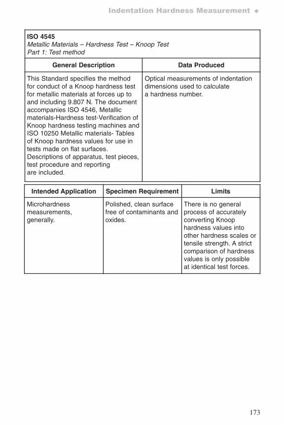
173
Indentation Hardness Measurement ♦
ISO 4545Metallic Materials – Hardness Test – Knoop TestPart 1: Test method
General Description Data Produced
This Standard specifies the methodfor conduct of a Knoop hardness testfor metallic materials at forces up toand including 9.807 N. The documentaccompanies ISO 4546, Metallicmaterials-Hardness test-Verification ofKnoop hardness testing machines andISO 10250 Metallic materials- Tablesof Knoop hardness values for use intests made on flat surfaces.Descriptions of apparatus, test pieces,test procedure and reportingare included.
Optical measurements of indentationdimensions used to calculatea hardness number.
Intended Application Specimen Requirement Limits
Microhardnessmeasurements,generally.
Polished, clean surfacefree of contaminants andoxides.
There is no generalprocess of accuratelyconverting Knoophardness values intoother hardness scales ortensile strength. A strictcomparison of hardnessvalues is only possibleat identical test forces.
7652_.qxd 9/27/2005 11:58 AM Page 173
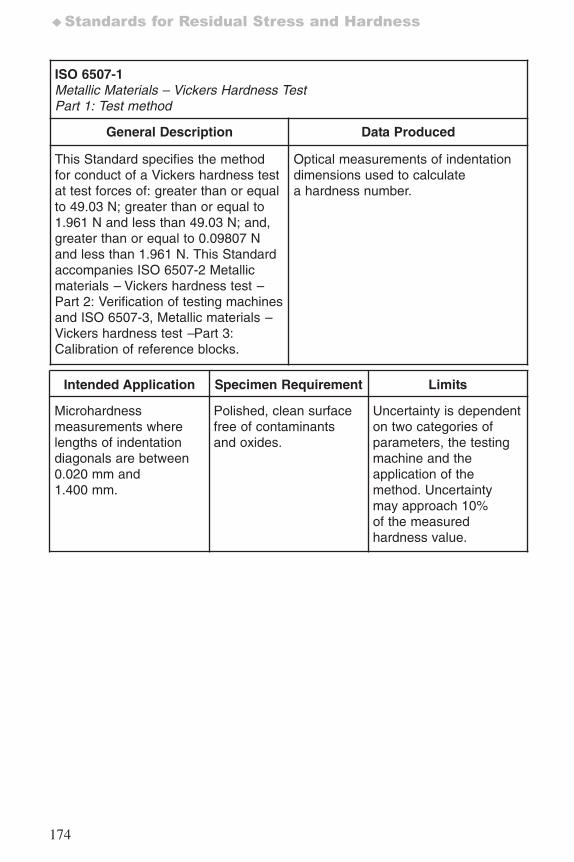
174
♦Standards for Residual Stress and Hardness
ISO 6507-1Metallic Materials – Vickers Hardness TestPart 1: Test method
General Description Data Produced
This Standard specifies the methodfor conduct of a Vickers hardness testat test forces of: greater than or equalto 49.03 N; greater than or equal to1.961 N and less than 49.03 N; and,greater than or equal to 0.09807 Nand less than 1.961 N. This Standardaccompanies ISO 6507-2 Metallicmaterials – Vickers hardness test –Part 2: Verification of testing machinesand ISO 6507-3, Metallic materials –Vickers hardness test –Part 3:Calibration of reference blocks.
Optical measurements of indentationdimensions used to calculatea hardness number.
Intended Application Specimen Requirement Limits
Microhardnessmeasurements wherelengths of indentationdiagonals are between0.020 mm and1.400 mm.
Polished, clean surfacefree of contaminantsand oxides.
Uncertainty is dependenton two categories ofparameters, the testingmachine and theapplication of themethod. Uncertaintymay approach 10%of the measuredhardness value.
7652_.qxd 9/27/2005 11:58 AM Page 174
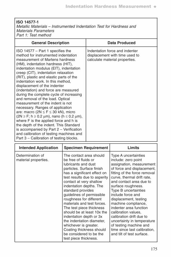
175
Indentation Hardness Measurement ♦
ISO 14577-1Metallic Materials – Instrumented Indentation Test for Hardness andMaterials ParametersPart 1: Test method
General Description Data Produced
ISO 14577 – Part 1 specifies themethod for instrumented indentationmeasurement of Martens hardness(HM), indentation hardness (HIT),indentation modulus (EIT), indentationcreep (CIT), indentation relaxation(RIT), plastic and elastic parts of theindentation work. In this method,displacement of the indenter(indentation) and force are measuredduring the complete cycle of increasingand removal of the load. Opticalmeasurement of the indent is notnecessary. Ranges of applicationare: macro (2N ≤ F ≤ 30 kN), micro(2N ≥ F; h ≥ 0.2 μm), nano (h ≤ 0.2 μm),where F is the applied force and h isthe depth of the indent. This Standardis accompanied by Part 2 – Verificationand calibration of testing machines andPart 3 – Calibration of testing blocks.
Indentation force and indenterdisplacement with time used tocalculate material properties.
Intended Application Specimen Requirement Limits
Determination ofmaterial properties.
The contact area shouldbe free of fluids orlubricants and dustparticles. Surface finishhas a significant effect ontest results due to asperitycontact at very shallowindentation depths. Thestandard providesguidelines of permissibleroughness for differentmaterials and test forces.The test piece thicknessshould be at least 10x theindentation depth or 3xthe indentation diameter,whichever is greater.Coating thickness shouldbe considered to be thetest piece thickness.
Type A uncertaintiesinclude: zero pointassignation, measurementof force and displacement,fitting of the force removalcurve, thermal drift rate,and contact area due tosurface roughness.Type B uncertaintiesinclude force anddisplacement, testingmachine compliance,indenter area functioncalibration values,calibration drift due touncertainty in temperatureof testing machine andtime since last calibration,and tilt of test surface.
7652_.qxd 9/27/2005 11:58 AM Page 175
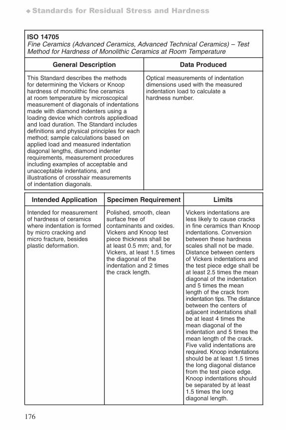
176
♦Standards for Residual Stress and Hardness
ISO 14705Fine Ceramics (Advanced Ceramics, Advanced Technical Ceramics) – TestMethod for Hardness of Monolithic Ceramics at Room Temperature
General Description Data Produced
This Standard describes the methodsfor determining the Vickers or Knoophardness of monolithic fine ceramicsat room temperature by microscopicalmeasurement of diagonals of indentationsmade with diamond indenters using aloading device which controls appliedloadand load duration. The Standard includesdefinitions and physical principles for eachmethod; sample calculations based onapplied load and measured indentationdiagonal lengths, diamond indenterrequirements, measurement proceduresincluding examples of acceptable andunacceptable indentations, andillustrations of crosshair measurementsof indentation diagonals.
Optical measurements of indentationdimensions used with the measuredindentation load to calculate ahardness number.
Intended Application Specimen Requirement Limits
Intended for measurementof hardness of ceramicswhere indentation is formedby micro cracking andmicro fracture, besidesplastic deformation.
Polished, smooth, cleansurface free ofcontaminants and oxides.Vickers and Knoop testpiece thickness shall beat least 0.5 mm; and, forVickers, at least 1.5 timesthe diagonal of theindentation and 2 timesthe crack length.
Vickers indentations areless likely to cause cracksin fine ceramics than Knoopindentations. Conversionbetween these hardnessscales shall not be made.Distance between centersof Vickers indentations andthe test piece edge shall beat least 2.5 times the meandiagonal of the indentationand 5 times the meanlength of the crack fromindentation tips. The distancebetween the centers ofadjacent indentations shallbe at least 4 times themean diagonal of theindentation and 5 times themean length of the crack.Five valid indentations arerequired. Knoop indentationsshould be at least 1.5 timesthe long diagonal distancefrom the test piece edge.Knoop indentations shouldbe separated by at least1.5 times the longdiagonal length.
7652_.qxd 9/27/2005 11:58 AM Page 176
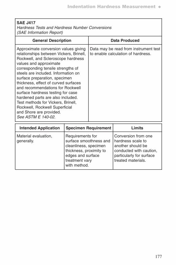
177
Indentation Hardness Measurement ♦
SAE J417 Hardness Tests and Hardness Number Conversions (SAE Information Report)
General Description Data Produced
Approximate conversion values givingrelationships between Vickers, Brinell,Rockwell, and Scleroscope hardnessvalues and approximatecorresponding tensile strengths ofsteels are included. Information onsurface preparation, specimenthickness, effect of curved surfacesand recommendations for Rockwellsurface hardness testing for casehardened parts are also included.Test methods for Vickers, Brinell,Rockwell, Rockwell Superficialand Shore are provided.See ASTM E 140-02.
Data may be read from instrument testto enable calculation of hardness.
Intended Application Specimen Requirement Limits
Material evaluation,generally.
Requirements forsurface smoothness andcleanliness, specimenthickness, proximity toedges and surfacetreatment varywith method.
Conversion from onehardness scale toanother should beconducted with caution,particularly for surfacetreated materials.
7652_.qxd 9/27/2005 11:58 AM Page 177
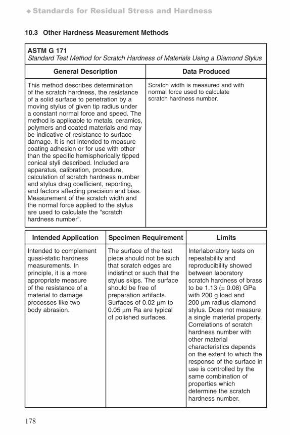
178
♦Standards for Residual Stress and Hardness
10.3 Other Hardness Measurement Methods
ASTM G 171Standard Test Method for Scratch Hardness of Materials Using a Diamond Stylus
General Description Data Produced
This method describes determinationof the scratch hardness, the resistanceof a solid surface to penetration by amoving stylus of given tip radius undera constant normal force and speed. Themethod is applicable to metals, ceramics,polymers and coated materials and maybe indicative of resistance to surfacedamage. It is not intended to measurecoating adhesion or for use with otherthan the specific hemispherically tippedconical styli described. Included areapparatus, calibration, procedure,calculation of scratch hardness numberand stylus drag coefficient, reporting,and factors affecting precision and bias.Measurement of the scratch width andthe normal force applied to the stylusare used to calculate the “scratchhardness number”.
Scratch width is measured and withnormal force used to calculatescratch hardness number.
Intended Application Specimen Requirement Limits
Intended to complementquasi-static hardnessmeasurements. Inprinciple, it is a moreappropriate measureof the resistance of amaterial to damageprocesses like twobody abrasion.
The surface of the testpiece should not be suchthat scratch edges areindistinct or such that thestylus skips. The surfaceshould be free ofpreparation artifacts.Surfaces of 0.02 μm to0.05 μm Ra are typicalof polished surfaces.
Interlaboratory tests onrepeatability andreproducibility showedbetween laboratoryscratch hardness of brassto be 1.13 (± 0.08) GPawith 200 g load and200 μm radius diamondstylus. Does not measurea single material property.Correlations of scratchhardness number withother materialcharacteristics dependson the extent to which theresponse of the surface inuse is controlled by thesame combination ofproperties whichdetermine the scratchhardness number.
7652_.qxd 9/27/2005 11:58 AM Page 178
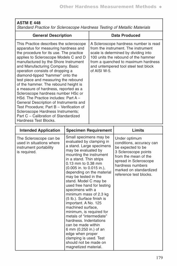
179
Other Hardness Measurement Methods ♦
ASTM E 448Standard Practice for Scleroscope Hardness Testing of Metallic Materials
General Description Data Produced
This Practice describes the scleroscopeapparatus for measuring hardness andthe procedure for its use. The practiceapplies to Scleroscope Models C and Dmanufactured by the Shore Instrumentand Manufacturing Company. Basicoperation consists of dropping adiamond-tipped “hammer” onto thetest piece and measuring the reboundof the hammer. The rebound height isa measure of hardness, reported as aScleroscope hardness number HSc orHSd. The Practice includes: Part A –General Description of Instruments andTest Procedure; Part B – Verification ofScleroscope Hardness Instruments;Part C – Calibration of StandardizedHardness Test Blocks.
A Scleroscope hardness number is readfrom the instrument. The instrumentscale is determined by dividing into100 units the rebound of the hammerfrom a quenched to maximum hardnessand untempered tool steel test blockof AISI W-5.
Intended Application Specimen Requirement Limits
The Scleroscope can beused in situations whereinstrument portabilityis required.
Small specimens may beevaluated by clamping ina stand. Large specimensmay be evaluated bymounting the instrumentin a stand. Thin strips0.13 mm to 0.38 mm(0.005 in. to 0.015 in.),depending on the materialmay be tested in thestand. Model C may beused free hand for testingspecimens with aminimum mass of 2.3 kg(5 lb.). Surface finish isimportant. A No. 125machined surface,minimum, is required formetals of “intermediate”hardness. Indentationscan be made within6 mm (0.250 in.) of anedge when properclamping is used. Testshould not be made onmagnetized material.
Under optimumconditions, accuracy canbe expected to be3 Scleroscope pointsfrom the mean of thespread in Scleroscopehardness numbersmarked on standardizedreference test blocks.
7652_.qxd 9/27/2005 11:58 AM Page 179
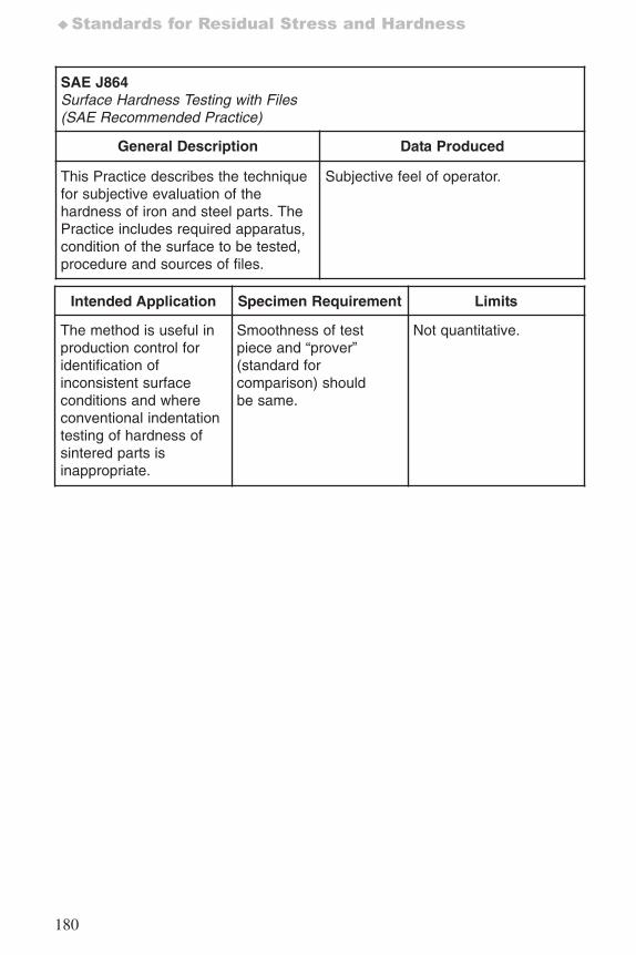
180
♦Standards for Residual Stress and Hardness
SAE J864Surface Hardness Testing with Files (SAE Recommended Practice)
General Description Data Produced
This Practice describes the techniquefor subjective evaluation of thehardness of iron and steel parts. ThePractice includes required apparatus,condition of the surface to be tested,procedure and sources of files.
Subjective feel of operator.
Intended Application Specimen Requirement Limits
The method is useful inproduction control foridentification ofinconsistent surfaceconditions and whereconventional indentationtesting of hardness ofsintered parts isinappropriate.
Smoothness of testpiece and “prover”(standard forcomparison) shouldbe same.
Not quantitative.
7652_.qxd 9/27/2005 11:58 AM Page 180
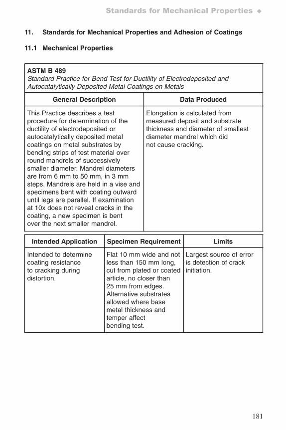
181
Standards for Mechanical Properties ♦
11. Standards for Mechanical Properties and Adhesion of Coatings
11.1 Mechanical Properties
ASTM B 489Standard Practice for Bend Test for Ductility of Electrodeposited andAutocatalytically Deposited Metal Coatings on Metals
General Description Data Produced
This Practice describes a testprocedure for determination of theductility of electrodeposited orautocatalytically deposited metalcoatings on metal substrates bybending strips of test material overround mandrels of successivelysmaller diameter. Mandrel diametersare from 6 mm to 50 mm, in 3 mmsteps. Mandrels are held in a vise andspecimens bent with coating outwarduntil legs are parallel. If examinationat 10x does not reveal cracks in thecoating, a new specimen is bentover the next smaller mandrel.
Elongation is calculated frommeasured deposit and substratethickness and diameter of smallestdiameter mandrel which didnot cause cracking.
Intended Application Specimen Requirement Limits
Intended to determinecoating resistanceto cracking duringdistortion.
Flat 10 mm wide and notless than 150 mm long,cut from plated or coatedarticle, no closer than25 mm from edges.Alternative substratesallowed where basemetal thickness andtemper affectbending test.
Largest source of erroris detection of crackinitiation.
7652_.qxd 9/27/2005 11:58 AM Page 181
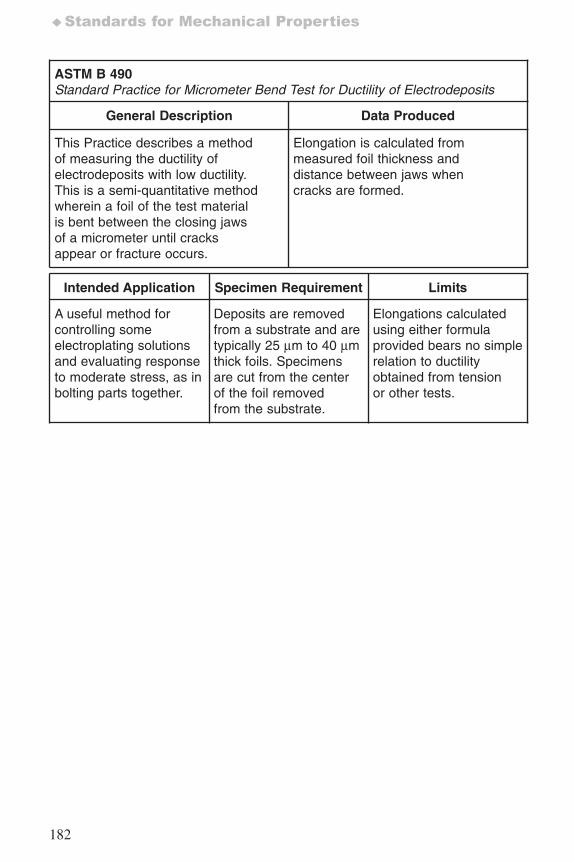
182
♦Standards for Mechanical Properties
ASTM B 490Standard Practice for Micrometer Bend Test for Ductility of Electrodeposits
General Description Data Produced
This Practice describes a methodof measuring the ductility ofelectrodeposits with low ductility.This is a semi-quantitative methodwherein a foil of the test materialis bent between the closing jawsof a micrometer until cracksappear or fracture occurs.
Elongation is calculated frommeasured foil thickness anddistance between jaws whencracks are formed.
Intended Application Specimen Requirement Limits
A useful method forcontrolling someelectroplating solutionsand evaluating responseto moderate stress, as inbolting parts together.
Deposits are removedfrom a substrate and aretypically 25 μm to 40 μmthick foils. Specimensare cut from the centerof the foil removedfrom the substrate.
Elongations calculatedusing either formulaprovided bears no simplerelation to ductilityobtained from tensionor other tests.
7652_.qxd 9/27/2005 11:58 AM Page 182
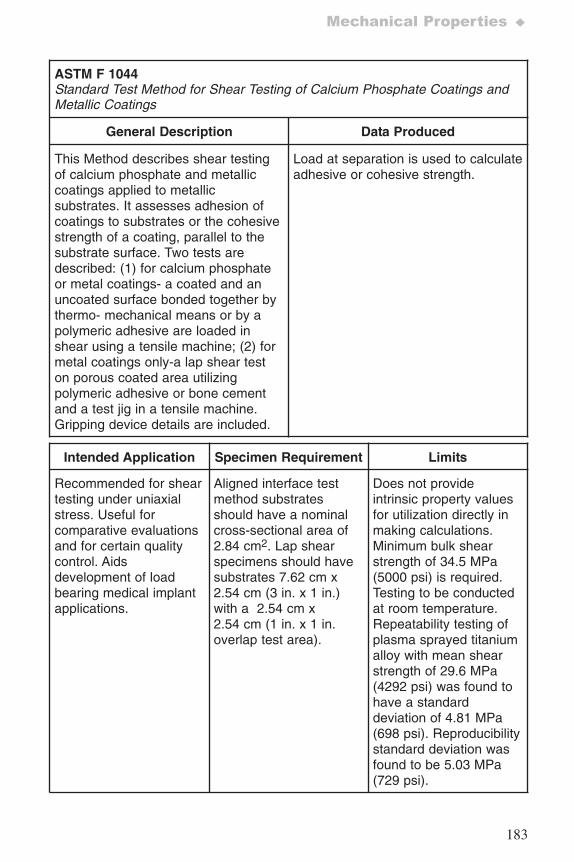
183
Mechanical Properties ♦
ASTM F 1044Standard Test Method for Shear Testing of Calcium Phosphate Coatings andMetallic Coatings
General Description Data Produced
This Method describes shear testingof calcium phosphate and metalliccoatings applied to metallicsubstrates. It assesses adhesion ofcoatings to substrates or the cohesivestrength of a coating, parallel to thesubstrate surface. Two tests aredescribed: (1) for calcium phosphateor metal coatings- a coated and anuncoated surface bonded together bythermo- mechanical means or by apolymeric adhesive are loaded inshear using a tensile machine; (2) formetal coatings only-a lap shear teston porous coated area utilizingpolymeric adhesive or bone cementand a test jig in a tensile machine.Gripping device details are included.
Load at separation is used to calculateadhesive or cohesive strength.
Intended Application Specimen Requirement Limits
Recommended for sheartesting under uniaxialstress. Useful forcomparative evaluationsand for certain qualitycontrol. Aidsdevelopment of loadbearing medical implantapplications.
Aligned interface testmethod substratesshould have a nominalcross-sectional area of2.84 cm2. Lap shearspecimens should havesubstrates 7.62 cm x2.54 cm (3 in. x 1 in.)with a 2.54 cm x2.54 cm (1 in. x 1 in.overlap test area).
Does not provideintrinsic property valuesfor utilization directly inmaking calculations.Minimum bulk shearstrength of 34.5 MPa(5000 psi) is required.Testing to be conductedat room temperature.Repeatability testing ofplasma sprayed titaniumalloy with mean shearstrength of 29.6 MPa(4292 psi) was found tohave a standarddeviation of 4.81 MPa(698 psi). Reproducibilitystandard deviation wasfound to be 5.03 MPa(729 psi).
7652_.qxd 9/27/2005 11:58 AM Page 183
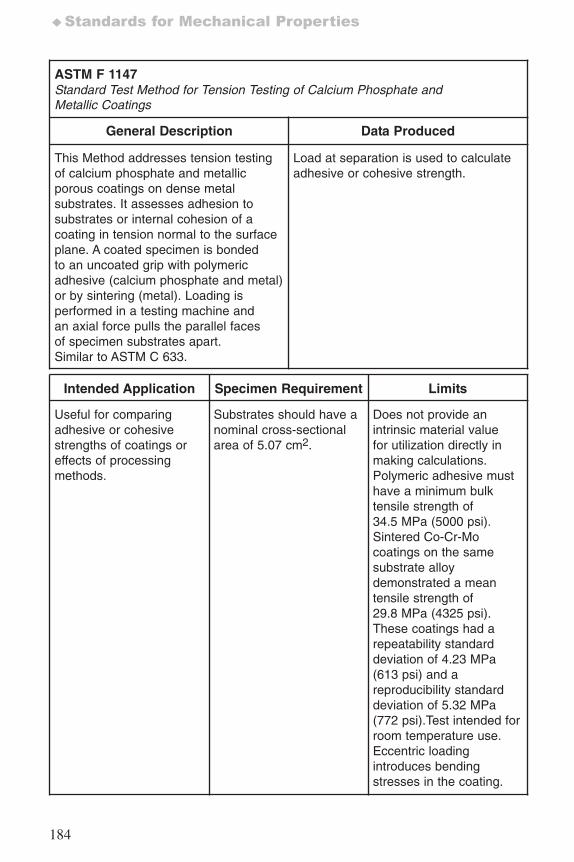
184
♦Standards for Mechanical Properties
ASTM F 1147Standard Test Method for Tension Testing of Calcium Phosphate andMetallic Coatings
General Description Data Produced
This Method addresses tension testingof calcium phosphate and metallicporous coatings on dense metalsubstrates. It assesses adhesion tosubstrates or internal cohesion of acoating in tension normal to the surfaceplane. A coated specimen is bondedto an uncoated grip with polymericadhesive (calcium phosphate and metal)or by sintering (metal). Loading isperformed in a testing machine andan axial force pulls the parallel facesof specimen substrates apart. Similar to ASTM C 633.
Load at separation is used to calculateadhesive or cohesive strength.
Intended Application Specimen Requirement Limits
Useful for comparingadhesive or cohesivestrengths of coatings oreffects of processingmethods.
Substrates should have anominal cross-sectionalarea of 5.07 cm2.
Does not provide anintrinsic material valuefor utilization directly inmaking calculations.Polymeric adhesive musthave a minimum bulktensile strength of34.5 MPa (5000 psi).Sintered Co-Cr-Mocoatings on the samesubstrate alloydemonstrated a meantensile strength of29.8 MPa (4325 psi).These coatings had arepeatability standarddeviation of 4.23 MPa(613 psi) and areproducibility standarddeviation of 5.32 MPa(772 psi).Test intended forroom temperature use.Eccentric loadingintroduces bendingstresses in the coating.
7652_.qxd 9/27/2005 11:58 AM Page 184
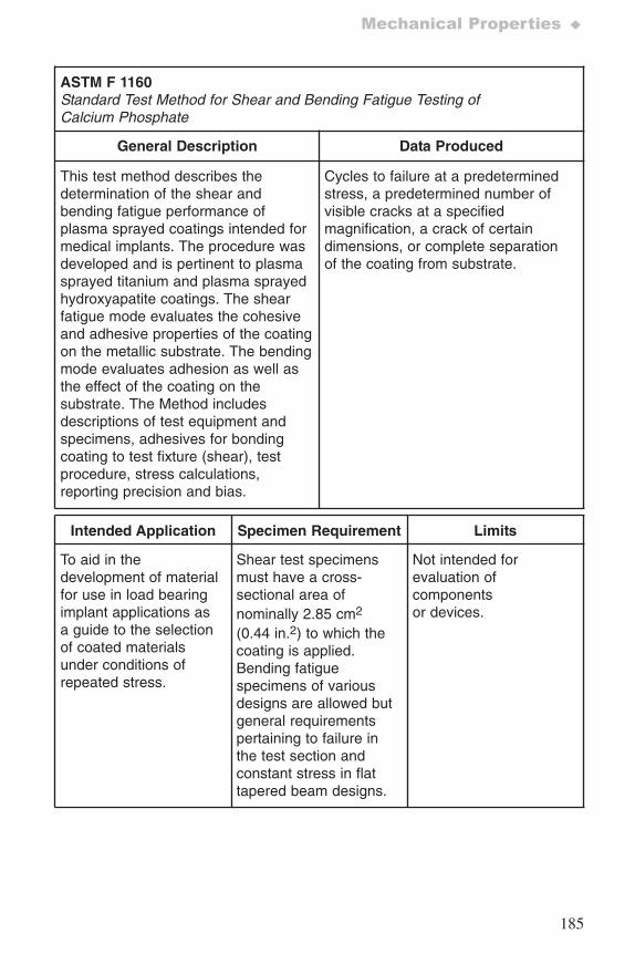
185
Mechanical Properties ♦
ASTM F 1160Standard Test Method for Shear and Bending Fatigue Testing ofCalcium Phosphate
General Description Data Produced
This test method describes thedetermination of the shear andbending fatigue performance ofplasma sprayed coatings intended formedical implants. The procedure wasdeveloped and is pertinent to plasmasprayed titanium and plasma sprayedhydroxyapatite coatings. The shearfatigue mode evaluates the cohesiveand adhesive properties of the coatingon the metallic substrate. The bendingmode evaluates adhesion as well asthe effect of the coating on thesubstrate. The Method includesdescriptions of test equipment andspecimens, adhesives for bondingcoating to test fixture (shear), testprocedure, stress calculations,reporting precision and bias.
Cycles to failure at a predeterminedstress, a predetermined number ofvisible cracks at a specifiedmagnification, a crack of certaindimensions, or complete separationof the coating from substrate.
Intended Application Specimen Requirement Limits
To aid in thedevelopment of materialfor use in load bearingimplant applications asa guide to the selectionof coated materialsunder conditions ofrepeated stress.
Shear test specimensmust have a cross-sectional area ofnominally 2.85 cm2
(0.44 in.2) to which thecoating is applied.Bending fatiguespecimens of variousdesigns are allowed butgeneral requirementspertaining to failure inthe test section andconstant stress in flattapered beam designs.
Not intended forevaluation ofcomponentsor devices.
7652_.qxd 9/27/2005 11:58 AM Page 185
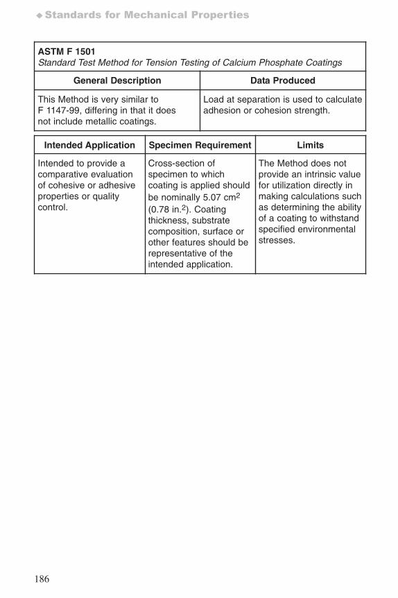
186
♦Standards for Mechanical Properties
ASTM F 1501Standard Test Method for Tension Testing of Calcium Phosphate Coatings
General Description Data Produced
This Method is very similar toF 1147-99, differing in that it doesnot include metallic coatings.
Load at separation is used to calculateadhesion or cohesion strength.
Intended Application Specimen Requirement Limits
Intended to provide acomparative evaluationof cohesive or adhesiveproperties or qualitycontrol.
Cross-section ofspecimen to whichcoating is applied shouldbe nominally 5.07 cm2
(0.78 in.2). Coatingthickness, substratecomposition, surface orother features should berepresentative of theintended application.
The Method does notprovide an intrinsic valuefor utilization directly inmaking calculations suchas determining the abilityof a coating to withstandspecified environmentalstresses.
7652_.qxd 9/27/2005 11:58 AM Page 186
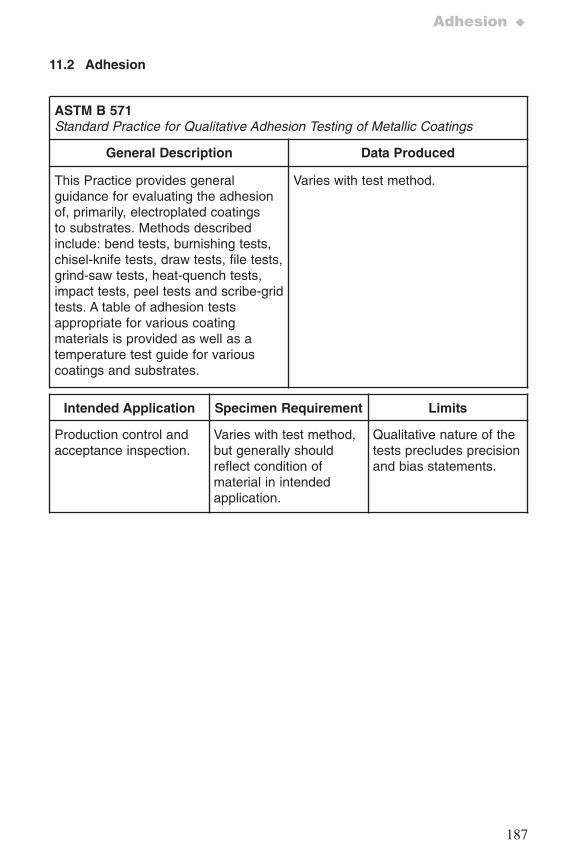
187
Adhesion ♦
11.2 Adhesion
ASTM B 571 Standard Practice for Qualitative Adhesion Testing of Metallic Coatings
General Description Data Produced
This Practice provides generalguidance for evaluating the adhesionof, primarily, electroplated coatingsto substrates. Methods describedinclude: bend tests, burnishing tests,chisel-knife tests, draw tests, file tests,grind-saw tests, heat-quench tests,impact tests, peel tests and scribe-gridtests. A table of adhesion testsappropriate for various coatingmaterials is provided as well as atemperature test guide for variouscoatings and substrates.
Varies with test method.
Intended Application Specimen Requirement Limits
Production control andacceptance inspection.
Varies with test method,but generally shouldreflect condition ofmaterial in intendedapplication.
Qualitative nature of thetests precludes precisionand bias statements.
7652_.qxd 9/27/2005 11:58 AM Page 187
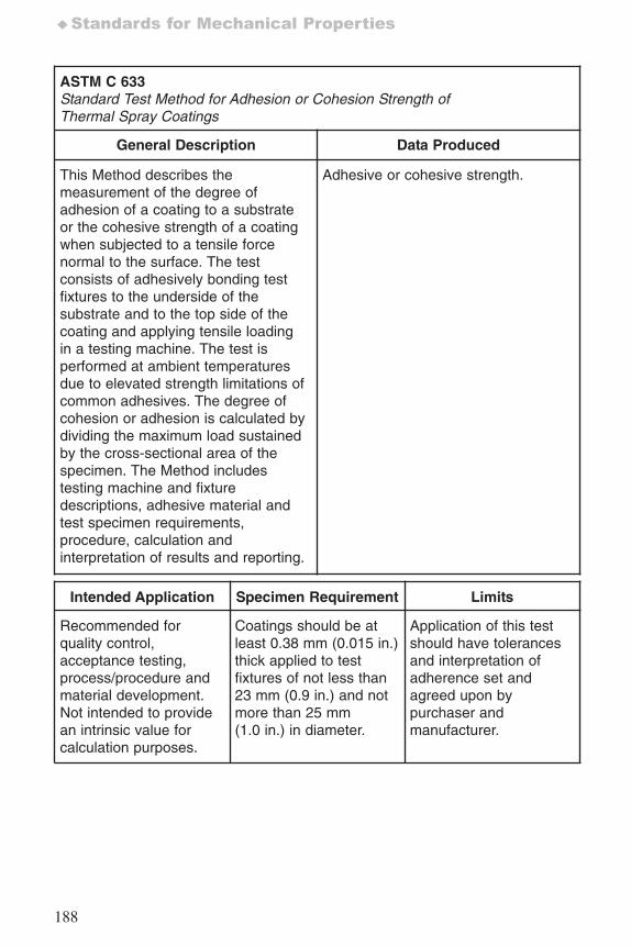
188
♦Standards for Mechanical Properties
ASTM C 633Standard Test Method for Adhesion or Cohesion Strength ofThermal Spray Coatings
General Description Data Produced
This Method describes themeasurement of the degree ofadhesion of a coating to a substrateor the cohesive strength of a coatingwhen subjected to a tensile forcenormal to the surface. The testconsists of adhesively bonding testfixtures to the underside of thesubstrate and to the top side of thecoating and applying tensile loadingin a testing machine. The test isperformed at ambient temperaturesdue to elevated strength limitations ofcommon adhesives. The degree ofcohesion or adhesion is calculated bydividing the maximum load sustainedby the cross-sectional area of thespecimen. The Method includestesting machine and fixturedescriptions, adhesive material andtest specimen requirements,procedure, calculation andinterpretation of results and reporting.
Adhesive or cohesive strength.
Intended Application Specimen Requirement Limits
Recommended forquality control,acceptance testing,process/procedure andmaterial development.Not intended to providean intrinsic value forcalculation purposes.
Coatings should be atleast 0.38 mm (0.015 in.)thick applied to testfixtures of not less than23 mm (0.9 in.) and notmore than 25 mm(1.0 in.) in diameter.
Application of this testshould have tolerancesand interpretation ofadherence set andagreed upon bypurchaser andmanufacturer.
7652_.qxd 9/27/2005 11:58 AM Page 188
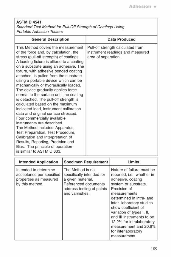
189
Adhesion ♦
ASTM D 4541Standard Test Method for Pull-Off Strength of Coatings UsingPortable Adhesion Testers
General Description Data Produced
This Method covers the measurementof the force and, by calculation, thestress (pull-off strength) of coatings.A loading fixture is affixed to a coatingon a substrate using an adhesive. Thefixture, with adhesive bonded coatingattached, is pulled from the substrateusing a portable device which can bemechanically or hydraulically loaded.The device gradually applies forcenormal to the surface until the coatingis detached. The pull-off strength iscalculated based on the maximumindicated load, instrument calibrationdata and original surface stressed.Four commercially availableinstruments are described.The Method includes: Apparatus,Test Preparation, Test Procedure,Calibration and Interpretation ofResults, Reporting, Precision andBias. The principle of operationis similar to ASTM C 633.
Pull-off strength calculated frominstrument readings and measuredarea of separation.
Intended Application Specimen Requirement Limits
Intended to determineacceptance per specifiedproperties as measuredby this method.
The Method is notspecifically intended fora given material. Referenced documentsaddress testing of paintsand varnishes.
Nature of failure must bereported, i.e., whether inadhesive, coatingsystem or substrate.Precision ofmeasurementsdetermined in intra- andinter- laboratory studiesshow coefficient ofvariation of types I, II,and III instruments to be12.2% for intralaboratorymeasurement and 20.6%for interlaboratorymeasurement.
7652_.qxd 9/27/2005 11:58 AM Page 189
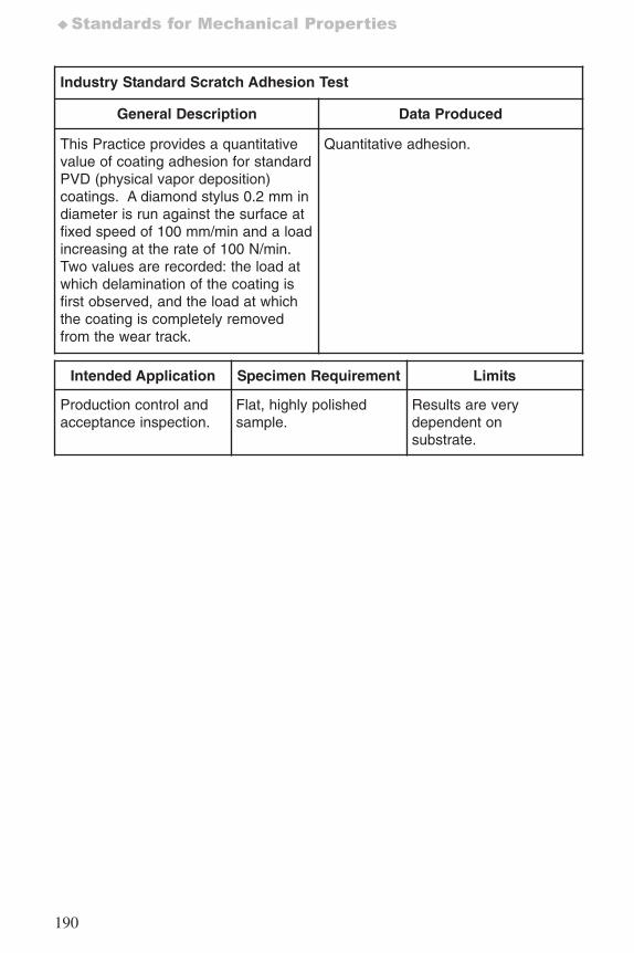
190
♦Standards for Mechanical Properties
Industry Standard Scratch Adhesion Test
General Description Data Produced
This Practice provides a quantitativevalue of coating adhesion for standardPVD (physical vapor deposition)coatings. A diamond stylus 0.2 mm indiameter is run against the surface atfixed speed of 100 mm/min and a loadincreasing at the rate of 100 N/min.Two values are recorded: the load atwhich delamination of the coating isfirst observed, and the load at whichthe coating is completely removedfrom the wear track.
Quantitative adhesion.
Intended Application Specimen Requirement Limits
Production control and acceptance inspection.
Flat, highly polishedsample.
Results are verydependent onsubstrate.
7652_.qxd 9/27/2005 11:58 AM Page 190
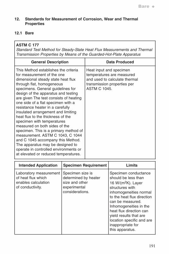
191
Bare ♦
12. Standards for Measurement of Corrosion, Wear and ThermalProperties
12.1 Bare
ASTM C 177Standard Test Method for Steady-State Heat Flux Measurements and ThermalTransmission Properties by Means of the Guarded-Hot-Plate Apparatus
General Description Data Produced
This Method establishes the criteriafor measurement of the onedimensional steady state heat fluxthrough flat, homogeneousspecimens. General guidelines fordesign of the apparatus and testingare given The test consists of heatingone side of a flat specimen with aresistance heater in a carefullyinsulated arrangement and limitingheat flux to the thickness of thespecimen with temperaturesmeasured on both sides of thespecimen. This is a primary method ofmeasurement. ASTM C 1043, C 1044and C 1045 accompany this Method.The apparatus may be designed tooperate in controlled environments orat elevated or reduced temperatures.
Heat input and specimentemperatures are measuredand used to calculate thermaltransmission properties perASTM C 1045.
Intended Application Specimen Requirement Limits
Laboratory measurementof heat flux whichenables calculationof conductivity.
Specimen size isdetermined by heatersize and otherexperimentalconsiderations.
Specimen conductanceshould be less than16 W/(m2K). Layerstructures withinhomogeneities normalto the heat flux directioncan be measured.Inhomogeneities in theheat flux direction canyield results that arelocation specific and areinappropriate forthis apparatus.
7652_.qxd 9/27/2005 11:58 AM Page 191
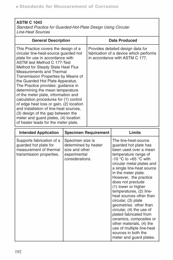
192
♦Standards for Measurement of Corrosion
ASTM C 1043Standard Practice for Guarded-Hot-Plate Design Using CircularLine-Heat Sources
General Description Data Produced
This Practice covers the design of acircular line-heat-source guarded hotplate for use in accordance withASTM test Method C 177-TestMethod for Steady State Heat FluxMeasurements and ThermalTransmission Properties by Means ofthe Guarded Hot Plate Apparatus.The Practice provides: guidance indetermining the mean temperatureof the meter plate, information andcalculation procedures for (1) controlof edge heat loss or gain, (2) locationand installation of line-heat sources,(3) design of the gap between themeter and guard plates, (4) locationof heater leads for the meter plate.
Provides detailed design data forfabrication of a device which performsin accordance with ASTM C 177.
Intended Application Specimen Requirement Limits
Supports fabrication of aguarded hot plate formeasurement of thermaltransmission properties.
Specimen size isdetermined by heatersize and otherexperimentalconsiderations.
The line-heat-sourceguarded hot plate hasbeen used over a meantemperature range of-10 °C to +65 °C withcircular metal plates anda single line-heat sourcein the meter plate.However, the practicedoes not preclude(1) lower or highertemperatures, (2) line-heat sources other thancircular, (3) plategeometries other thancircular, (4) the use ofplated fabricated fromceramics, composites orother materials, (4) theuse of multiple line-heatsources in both themeter and guard plates.
7652_.qxd 9/27/2005 11:58 AM Page 192
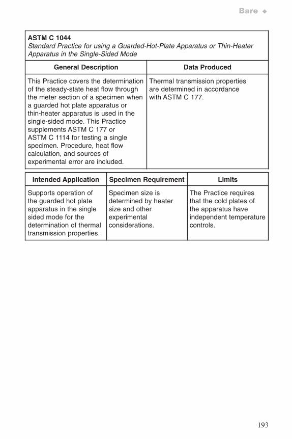
193
Bare ♦
ASTM C 1044Standard Practice for using a Guarded-Hot-Plate Apparatus or Thin-HeaterApparatus in the Single-Sided Mode
General Description Data Produced
This Practice covers the determinationof the steady-state heat flow throughthe meter section of a specimen whena guarded hot plate apparatus orthin-heater apparatus is used in thesingle-sided mode. This Practicesupplements ASTM C 177 orASTM C 1114 for testing a singlespecimen. Procedure, heat flowcalculation, and sources ofexperimental error are included.
Thermal transmission propertiesare determined in accordancewith ASTM C 177.
Intended Application Specimen Requirement Limits
Supports operation ofthe guarded hot plateapparatus in the singlesided mode for thedetermination of thermaltransmission properties.
Specimen size isdetermined by heatersize and otherexperimentalconsiderations.
The Practice requiresthat the cold plates ofthe apparatus haveindependent temperaturecontrols.
7652_.qxd 9/27/2005 11:58 AM Page 193
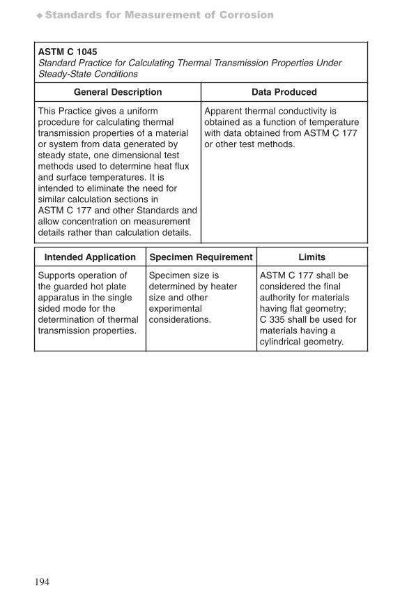
194
♦Standards for Measurement of Corrosion
ASTM C 1045Standard Practice for Calculating Thermal Transmission Properties UnderSteady-State Conditions
General Description Data Produced
This Practice gives a uniformprocedure for calculating thermaltransmission properties of a materialor system from data generated bysteady state, one dimensional testmethods used to determine heat fluxand surface temperatures. It isintended to eliminate the need forsimilar calculation sections inASTM C 177 and other Standards andallow concentration on measurementdetails rather than calculation details.
Apparent thermal conductivity isobtained as a function of temperaturewith data obtained from ASTM C 177or other test methods.
Intended Application Specimen Requirement Limits
Supports operation ofthe guarded hot plateapparatus in the singlesided mode for thedetermination of thermaltransmission properties.
Specimen size isdetermined by heatersize and otherexperimentalconsiderations.
ASTM C 177 shall beconsidered the finalauthority for materialshaving flat geometry;C 335 shall be used formaterials having acylindrical geometry.
7652_.qxd 9/27/2005 11:58 AM Page 194
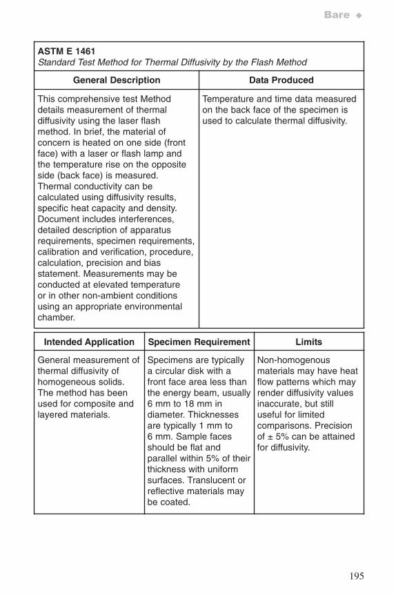
195
Bare ♦
ASTM E 1461Standard Test Method for Thermal Diffusivity by the Flash Method
General Description Data Produced
This comprehensive test Methoddetails measurement of thermaldiffusivity using the laser flashmethod. In brief, the material ofconcern is heated on one side (frontface) with a laser or flash lamp andthe temperature rise on the oppositeside (back face) is measured.Thermal conductivity can becalculated using diffusivity results,specific heat capacity and density.Document includes interferences,detailed description of apparatusrequirements, specimen requirements,calibration and verification, procedure,calculation, precision and biasstatement. Measurements may beconducted at elevated temperatureor in other non-ambient conditionsusing an appropriate environmentalchamber.
Temperature and time data measuredon the back face of the specimen isused to calculate thermal diffusivity.
Intended Application Specimen Requirement Limits
General measurement ofthermal diffusivity ofhomogeneous solids.The method has beenused for composite andlayered materials.
Specimens are typicallya circular disk with afront face area less thanthe energy beam, usually6 mm to 18 mm indiameter. Thicknessesare typically 1 mm to6 mm. Sample facesshould be flat andparallel within 5% of theirthickness with uniformsurfaces. Translucent orreflective materials maybe coated.
Non-homogenousmaterials may have heatflow patterns which mayrender diffusivity valuesinaccurate, but stilluseful for limitedcomparisons. Precisionof ± 5% can be attainedfor diffusivity.
7652_.qxd 9/27/2005 11:58 AM Page 195
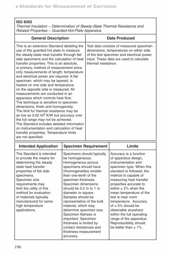
196
♦Standards for Measurement of Corrosion
ISO 8302Thermal Insulation – Determination of Steady-State Thermal Resistance andRelated Properties – Guarded-Hot-Plate Apparatus
General Description Data Produced
This is an extensive Standard detailing theuse of the guarded hot plate to measurethe steady-state heat transfer through flatslab specimens and the calculation of heattransfer properties. This is an absolute,or primary, method of measurement sinceonly measurements of length; temperatureand electrical power are required. A flatspecimen, which may be layered, isheated on one side and temperatureon the opposite side is measured. Allmeasurements are conducted in anapparatus which controls heat flow.The technique is sensitive to specimendimensions, finish and homogeneity.The limit for thermal resistance may beas low as 0.02 m2 K/W but accuracy overthe full range may not be achieved.The Standard includes detailed informationon instrumentation and calculation of heattransfer properties. Temperature limitsare not specified.
Test data consists of measured specimendimensions, temperatures on either sideof the test specimen and electrical powerinput. These data are used to calculatethermal resistance.
Intended Application Specimen Requirement Limits
The Standard is intendedto provide the means fordetermining the steadystate heat transferproperties of flat slabspecimens.Specimen sizerequirements maylimit the utility of thismethod for evaluationof materials typicallymanufactured for somehigh temperatureapplications.
Specimens should typicallybe homogeneous.Homogeneous porousspecimens should haveinhomogeneities smallerthan one-tenth of thespecimen thickness.Specimen dimensionsshould be 0.2 m to 1 mdiameter or square.Samples should berepresentative of the bulkmaterial, which maydetermine specimen size.Specimen flatness isimportant. Specimenthickness is limited bycontact resistances andthickness measurementaccuracy.
Accuracy is a functionof apparatus design,instrumentation andspecimen type. When thisstandard is followed, themethod is capable ofmeasuring heat transferproperties accurate towithin ± 2% when themean temperature of thetest is near roomtemperature. Accuracyof ± 5% should beobtainable anywherewithin the full operatingrange of the apparatus.Reproducibility shouldbe better than ± 1%.
7652_.qxd 9/27/2005 11:58 AM Page 196
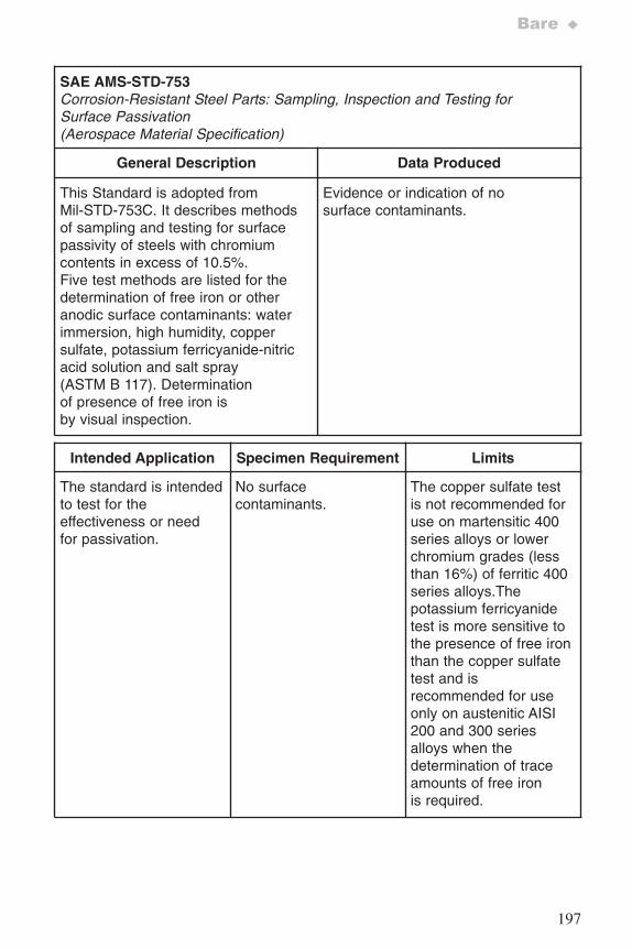
197
Bare ♦
SAE AMS-STD-753Corrosion-Resistant Steel Parts: Sampling, Inspection and Testing forSurface Passivation(Aerospace Material Specification)
General Description Data Produced
This Standard is adopted fromMil-STD-753C. It describes methodsof sampling and testing for surfacepassivity of steels with chromiumcontents in excess of 10.5%.Five test methods are listed for thedetermination of free iron or otheranodic surface contaminants: waterimmersion, high humidity, coppersulfate, potassium ferricyanide-nitricacid solution and salt spray(ASTM B 117). Determinationof presence of free iron isby visual inspection.
Evidence or indication of nosurface contaminants.
Intended Application Specimen Requirement Limits
The standard is intendedto test for theeffectiveness or needfor passivation.
No surfacecontaminants.
The copper sulfate testis not recommended foruse on martensitic 400series alloys or lowerchromium grades (lessthan 16%) of ferritic 400series alloys.Thepotassium ferricyanidetest is more sensitive tothe presence of free ironthan the copper sulfatetest and isrecommended for useonly on austenitic AISI200 and 300 seriesalloys when thedetermination of traceamounts of free ironis required.
7652_.qxd 9/27/2005 11:58 AM Page 197
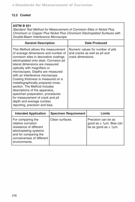
198
♦Standards for Measurement of Corrosion
12.2 Coated
ASTM B 651Standard Test Method for Measurement of Corrosion Sites in Nickel PlusChromium or Copper Plus Nickel Plus Chromium Electroplated Surfaces withDouble-Beam Interference Microscope
General Description Data Produced
This Method allows the measurementof average dimensions and number ofcorrosion sites in decorative coatingselectroplated onto steel. Corrosion pitlateral dimensions are measuredoptically with magnifiers ormicroscopes. Depths are measuredwith an interference microscope.Coating thickness is measured on ametallographically prepared cross-section. The Method includesdescriptions of the apparatus,specimen preparation, proceduresfor measurement of crack and pitdepth and average number,reporting, precision and bias.
Numeric values for number of pitsand cracks as well as pit andcrack dimensions.
Intended Application Specimen Requirement Limits
For comparing therelative corrosionresistance of differentelectroplating systemsand for comparing thecorrosiveness of differentenvironments.
Clean surfaces. Precision can be asgood as ± 1μm. Bias canbe as good as ± 1μm.
7652_.qxd 9/27/2005 11:58 AM Page 198
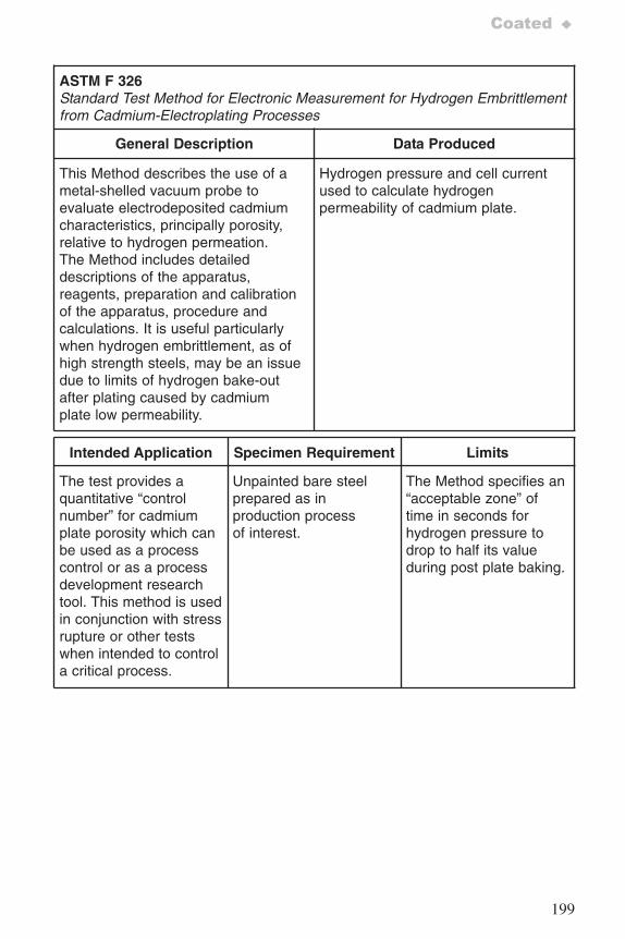
199
Coated ♦
ASTM F 326Standard Test Method for Electronic Measurement for Hydrogen Embrittlementfrom Cadmium-Electroplating Processes
General Description Data Produced
This Method describes the use of ametal-shelled vacuum probe toevaluate electrodeposited cadmiumcharacteristics, principally porosity,relative to hydrogen permeation.The Method includes detaileddescriptions of the apparatus,reagents, preparation and calibrationof the apparatus, procedure andcalculations. It is useful particularlywhen hydrogen embrittlement, as ofhigh strength steels, may be an issuedue to limits of hydrogen bake-outafter plating caused by cadmiumplate low permeability.
Hydrogen pressure and cell currentused to calculate hydrogenpermeability of cadmium plate.
Intended Application Specimen Requirement Limits
The test provides aquantitative “controlnumber” for cadmiumplate porosity which canbe used as a processcontrol or as a processdevelopment researchtool. This method is usedin conjunction with stressrupture or other testswhen intended to controla critical process.
Unpainted bare steelprepared as inproduction processof interest.
The Method specifies an“acceptable zone” oftime in seconds forhydrogen pressure todrop to half its valueduring post plate baking.
7652_.qxd 9/27/2005 11:58 AM Page 199
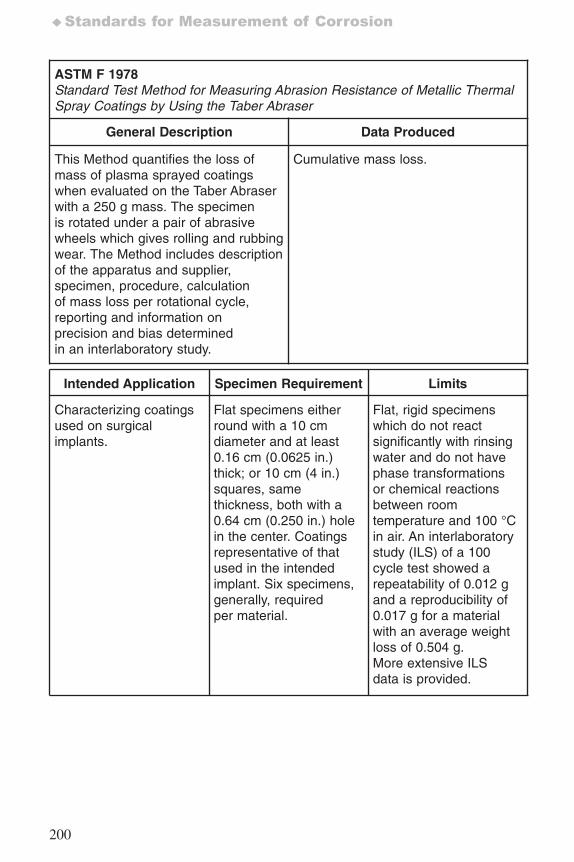
200
♦Standards for Measurement of Corrosion
ASTM F 1978Standard Test Method for Measuring Abrasion Resistance of Metallic ThermalSpray Coatings by Using the Taber Abraser
General Description Data Produced
This Method quantifies the loss ofmass of plasma sprayed coatingswhen evaluated on the Taber Abraserwith a 250 g mass. The specimenis rotated under a pair of abrasivewheels which gives rolling and rubbingwear. The Method includes descriptionof the apparatus and supplier,specimen, procedure, calculationof mass loss per rotational cycle,reporting and information onprecision and bias determinedin an interlaboratory study.
Cumulative mass loss.
Intended Application Specimen Requirement Limits
Characterizing coatingsused on surgicalimplants.
Flat specimens eitherround with a 10 cmdiameter and at least0.16 cm (0.0625 in.)thick; or 10 cm (4 in.)squares, samethickness, both with a0.64 cm (0.250 in.) holein the center. Coatingsrepresentative of thatused in the intendedimplant. Six specimens,generally, requiredper material.
Flat, rigid specimenswhich do not reactsignificantly with rinsingwater and do not havephase transformationsor chemical reactionsbetween roomtemperature and 100 °Cin air. An interlaboratorystudy (ILS) of a 100cycle test showed arepeatability of 0.012 gand a reproducibility of0.017 g for a materialwith an average weightloss of 0.504 g.More extensive ILSdata is provided.
7652_.qxd 9/27/2005 11:58 AM Page 200
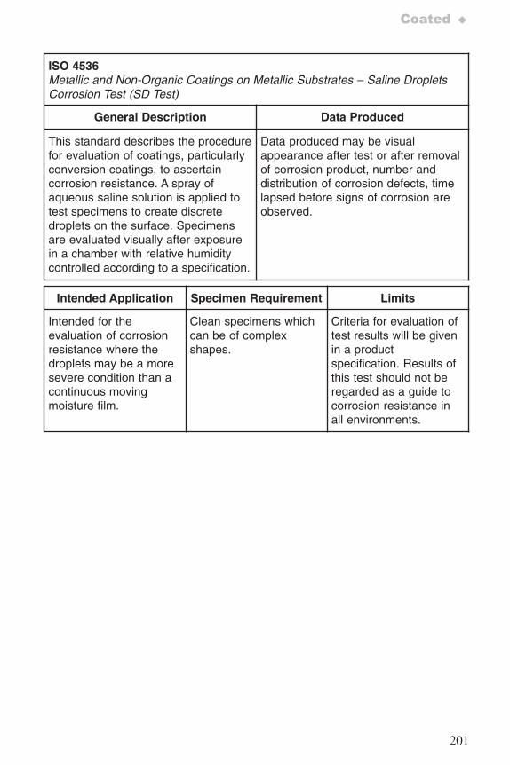
201
Coated ♦
ISO 4536Metallic and Non-Organic Coatings on Metallic Substrates – Saline DropletsCorrosion Test (SD Test)
General Description Data Produced
This standard describes the procedurefor evaluation of coatings, particularlyconversion coatings, to ascertaincorrosion resistance. A spray ofaqueous saline solution is applied totest specimens to create discretedroplets on the surface. Specimensare evaluated visually after exposurein a chamber with relative humiditycontrolled according to a specification.
Data produced may be visualappearance after test or after removalof corrosion product, number anddistribution of corrosion defects, timelapsed before signs of corrosion areobserved.
Intended Application Specimen Requirement Limits
Intended for theevaluation of corrosionresistance where thedroplets may be a moresevere condition than acontinuous movingmoisture film.
Clean specimens whichcan be of complexshapes.
Criteria for evaluation oftest results will be givenin a productspecification. Results ofthis test should not beregarded as a guide tocorrosion resistance inall environments.
7652_.qxd 9/27/2005 11:58 AM Page 201
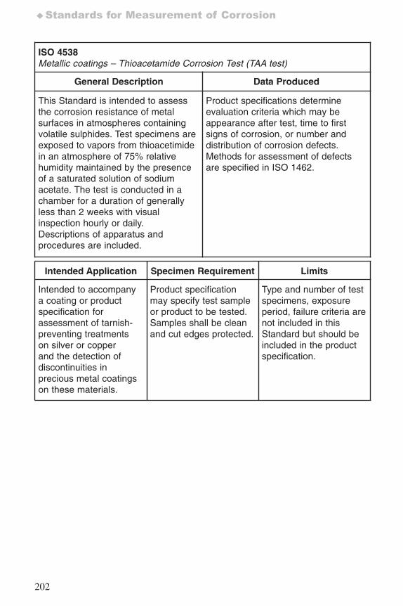
202
♦Standards for Measurement of Corrosion
ISO 4538 Metallic coatings – Thioacetamide Corrosion Test (TAA test)
General Description Data Produced
This Standard is intended to assessthe corrosion resistance of metalsurfaces in atmospheres containingvolatile sulphides. Test specimens areexposed to vapors from thioacetimidein an atmosphere of 75% relativehumidity maintained by the presenceof a saturated solution of sodiumacetate. The test is conducted in achamber for a duration of generallyless than 2 weeks with visualinspection hourly or daily.Descriptions of apparatus andprocedures are included.
Product specifications determineevaluation criteria which may beappearance after test, time to firstsigns of corrosion, or number anddistribution of corrosion defects.Methods for assessment of defectsare specified in ISO 1462.
Intended Application Specimen Requirement Limits
Intended to accompanya coating or productspecification forassessment of tarnish-preventing treatmentson silver or copperand the detection ofdiscontinuities inprecious metal coatingson these materials.
Product specificationmay specify test sampleor product to be tested.Samples shall be cleanand cut edges protected.
Type and number of testspecimens, exposureperiod, failure criteria arenot included in thisStandard but should beincluded in the productspecification.
7652_.qxd 9/27/2005 11:58 AM Page 202
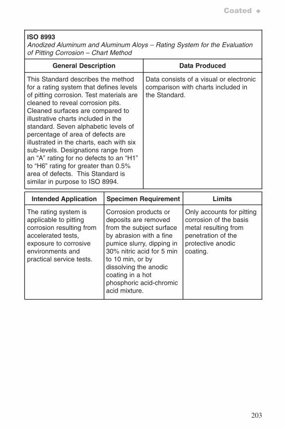
203
Coated ♦
ISO 8993Anodized Aluminum and Aluminum Aloys – Rating System for the Evaluationof Pitting Corrosion – Chart Method
General Description Data Produced
This Standard describes the methodfor a rating system that defines levelsof pitting corrosion. Test materials arecleaned to reveal corrosion pits.Cleaned surfaces are compared toillustrative charts included in thestandard. Seven alphabetic levels ofpercentage of area of defects areillustrated in the charts, each with sixsub-levels. Designations range froman “A” rating for no defects to an “H1”to “H6” rating for greater than 0.5%area of defects. This Standard issimilar in purpose to ISO 8994.
Data consists of a visual or electroniccomparison with charts included inthe Standard.
Intended Application Specimen Requirement Limits
The rating system isapplicable to pittingcorrosion resulting fromaccelerated tests,exposure to corrosiveenvironments andpractical service tests.
Corrosion products ordeposits are removedfrom the subject surfaceby abrasion with a finepumice slurry, dipping in30% nitric acid for 5 minto 10 min, or bydissolving the anodiccoating in a hotphosphoric acid-chromicacid mixture.
Only accounts for pittingcorrosion of the basismetal resulting frompenetration of theprotective anodiccoating.
7652_.qxd 9/27/2005 11:58 AM Page 203
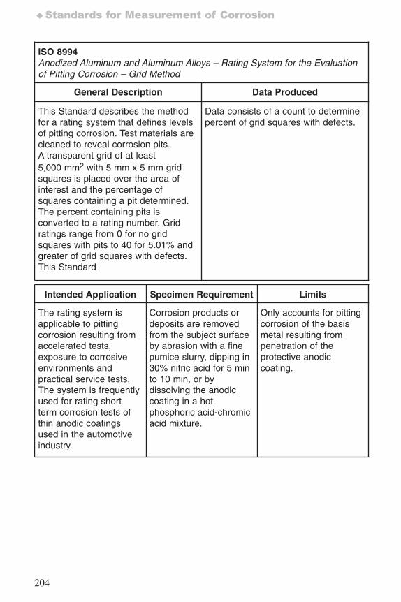
204
♦Standards for Measurement of Corrosion
ISO 8994Anodized Aluminum and Aluminum Alloys – Rating System for the Evaluationof Pitting Corrosion – Grid Method
General Description Data Produced
This Standard describes the methodfor a rating system that defines levelsof pitting corrosion. Test materials arecleaned to reveal corrosion pits.A transparent grid of at least5,000 mm2 with 5 mm x 5 mm gridsquares is placed over the area ofinterest and the percentage ofsquares containing a pit determined.The percent containing pits isconverted to a rating number. Gridratings range from 0 for no gridsquares with pits to 40 for 5.01% andgreater of grid squares with defects.This Standard
Data consists of a count to determinepercent of grid squares with defects.
Intended Application Specimen Requirement Limits
The rating system isapplicable to pittingcorrosion resulting fromaccelerated tests,exposure to corrosiveenvironments andpractical service tests.The system is frequentlyused for rating shortterm corrosion tests ofthin anodic coatingsused in the automotiveindustry.
Corrosion products ordeposits are removedfrom the subject surfaceby abrasion with a finepumice slurry, dipping in30% nitric acid for 5 minto 10 min, or bydissolving the anodiccoating in a hotphosphoric acid-chromicacid mixture.
Only accounts for pittingcorrosion of the basismetal resulting frompenetration of theprotective anodiccoating.
7652_.qxd 9/27/2005 11:58 AM Page 204
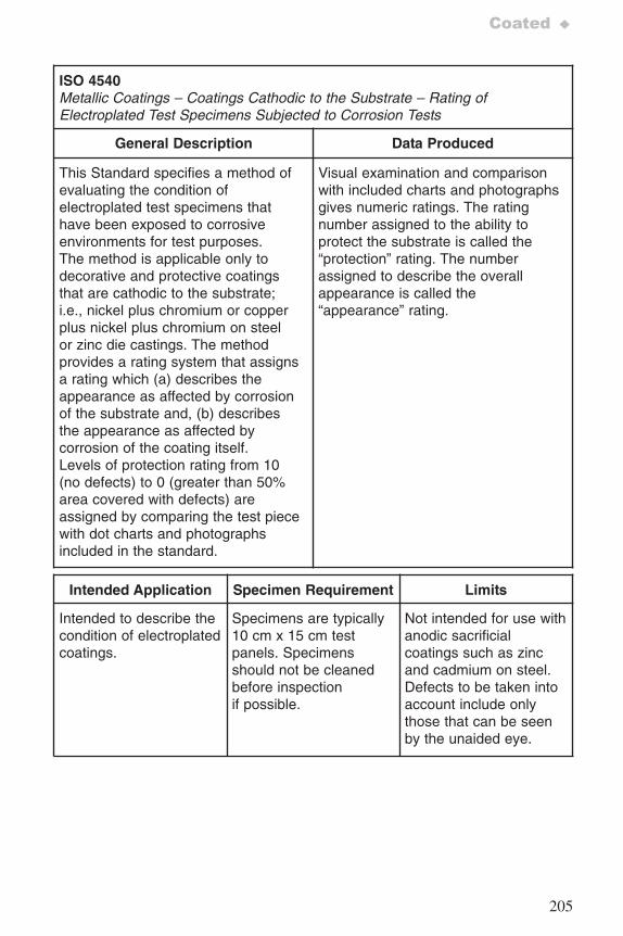
205
Coated ♦
ISO 4540Metallic Coatings – Coatings Cathodic to the Substrate – Rating ofElectroplated Test Specimens Subjected to Corrosion Tests
General Description Data Produced
This Standard specifies a method ofevaluating the condition ofelectroplated test specimens thathave been exposed to corrosiveenvironments for test purposes.The method is applicable only todecorative and protective coatingsthat are cathodic to the substrate;i.e., nickel plus chromium or copperplus nickel plus chromium on steelor zinc die castings. The methodprovides a rating system that assignsa rating which (a) describes theappearance as affected by corrosionof the substrate and, (b) describesthe appearance as affected bycorrosion of the coating itself.Levels of protection rating from 10(no defects) to 0 (greater than 50%area covered with defects) areassigned by comparing the test piecewith dot charts and photographsincluded in the standard.
Visual examination and comparisonwith included charts and photographsgives numeric ratings. The ratingnumber assigned to the ability toprotect the substrate is called the“protection” rating. The numberassigned to describe the overallappearance is called the“appearance” rating.
Intended Application Specimen Requirement Limits
Intended to describe thecondition of electroplatedcoatings.
Specimens are typically10 cm x 15 cm testpanels. Specimensshould not be cleanedbefore inspectionif possible.
Not intended for use withanodic sacrificialcoatings such as zincand cadmium on steel.Defects to be taken intoaccount include onlythose that can be seenby the unaided eye.
7652_.qxd 9/27/2005 11:58 AM Page 205
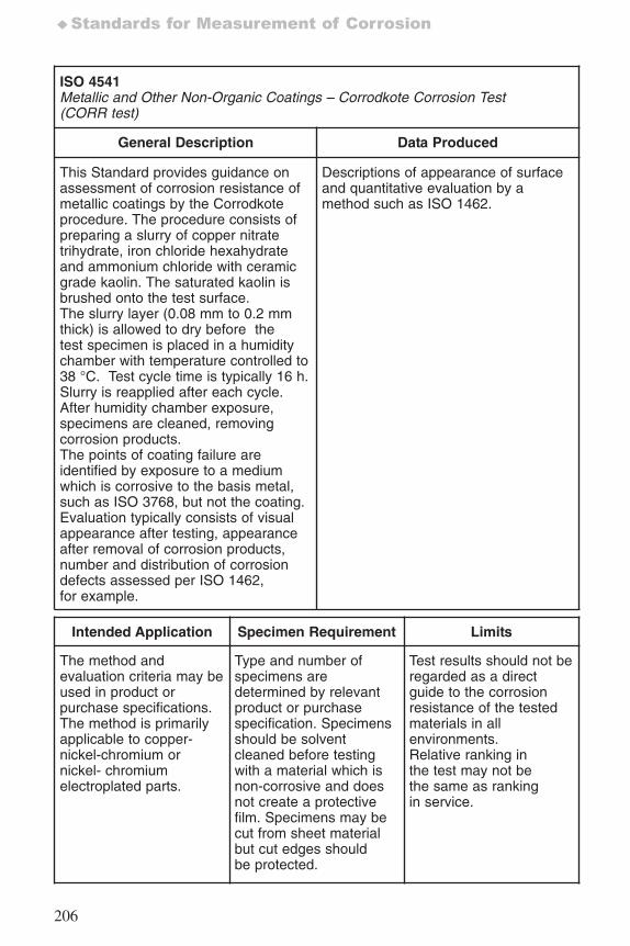
206
♦Standards for Measurement of Corrosion
ISO 4541Metallic and Other Non-Organic Coatings – Corrodkote Corrosion Test(CORR test)
General Description Data Produced
This Standard provides guidance onassessment of corrosion resistance ofmetallic coatings by the Corrodkoteprocedure. The procedure consists ofpreparing a slurry of copper nitratetrihydrate, iron chloride hexahydrateand ammonium chloride with ceramicgrade kaolin. The saturated kaolin isbrushed onto the test surface.The slurry layer (0.08 mm to 0.2 mmthick) is allowed to dry before thetest specimen is placed in a humiditychamber with temperature controlled to38 °C. Test cycle time is typically 16 h.Slurry is reapplied after each cycle.After humidity chamber exposure,specimens are cleaned, removingcorrosion products.The points of coating failure areidentified by exposure to a mediumwhich is corrosive to the basis metal,such as ISO 3768, but not the coating.Evaluation typically consists of visualappearance after testing, appearanceafter removal of corrosion products,number and distribution of corrosiondefects assessed per ISO 1462,for example.
Descriptions of appearance of surfaceand quantitative evaluation by amethod such as ISO 1462.
Intended Application Specimen Requirement Limits
The method andevaluation criteria may beused in product orpurchase specifications.The method is primarilyapplicable to copper-nickel-chromium ornickel- chromiumelectroplated parts.
Type and number ofspecimens aredetermined by relevantproduct or purchasespecification. Specimensshould be solventcleaned before testingwith a material which isnon-corrosive and doesnot create a protectivefilm. Specimens may becut from sheet materialbut cut edges shouldbe protected.
Test results should not beregarded as a directguide to the corrosionresistance of the testedmaterials in allenvironments.Relative ranking inthe test may not bethe same as rankingin service.
7652_.qxd 9/27/2005 11:58 AM Page 206
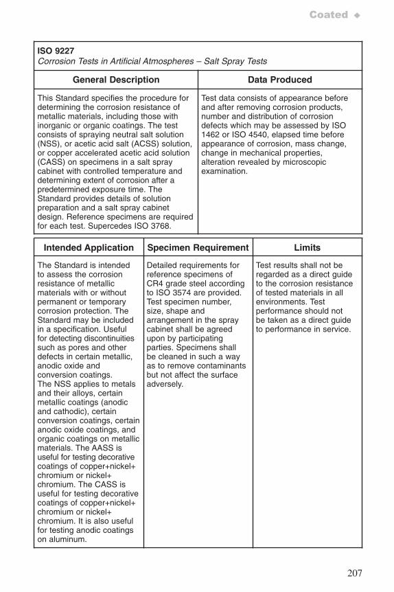
207
Coated ♦
ISO 9227Corrosion Tests in Artificial Atmospheres – Salt Spray Tests
General Description Data Produced
This Standard specifies the procedure fordetermining the corrosion resistance ofmetallic materials, including those withinorganic or organic coatings. The testconsists of spraying neutral salt solution(NSS), or acetic acid salt (ACSS) solution,or copper accelerated acetic acid solution(CASS) on specimens in a salt spraycabinet with controlled temperature anddetermining extent of corrosion after apredetermined exposure time. TheStandard provides details of solutionpreparation and a salt spray cabinetdesign. Reference specimens are requiredfor each test. Supercedes ISO 3768.
Test data consists of appearance beforeand after removing corrosion products,number and distribution of corrosiondefects which may be assessed by ISO1462 or ISO 4540, elapsed time beforeappearance of corrosion, mass change,change in mechanical properties,alteration revealed by microscopicexamination.
Intended Application Specimen Requirement Limits
The Standard is intendedto assess the corrosionresistance of metallicmaterials with or withoutpermanent or temporarycorrosion protection. TheStandard may be includedin a specification. Usefulfor detecting discontinuitiessuch as pores and otherdefects in certain metallic,anodic oxide andconversion coatings.The NSS applies to metalsand their alloys, certainmetallic coatings (anodicand cathodic), certainconversion coatings, certainanodic oxide coatings, andorganic coatings on metallicmaterials. The AASS isuseful for testing decorativecoatings of copper+nickel+chromium or nickel+chromium. The CASS isuseful for testing decorativecoatings of copper+nickel+chromium or nickel+chromium. It is also usefulfor testing anodic coatingson aluminum.
Detailed requirements forreference specimens ofCR4 grade steel accordingto ISO 3574 are provided.Test specimen number,size, shape andarrangement in the spraycabinet shall be agreedupon by participatingparties. Specimens shallbe cleaned in such a wayas to remove contaminantsbut not affect the surfaceadversely.
Test results shall not beregarded as a direct guideto the corrosion resistanceof tested materials in allenvironments. Testperformance should notbe taken as a direct guideto performance in service.
7652_.qxd 9/27/2005 11:58 AM Page 207
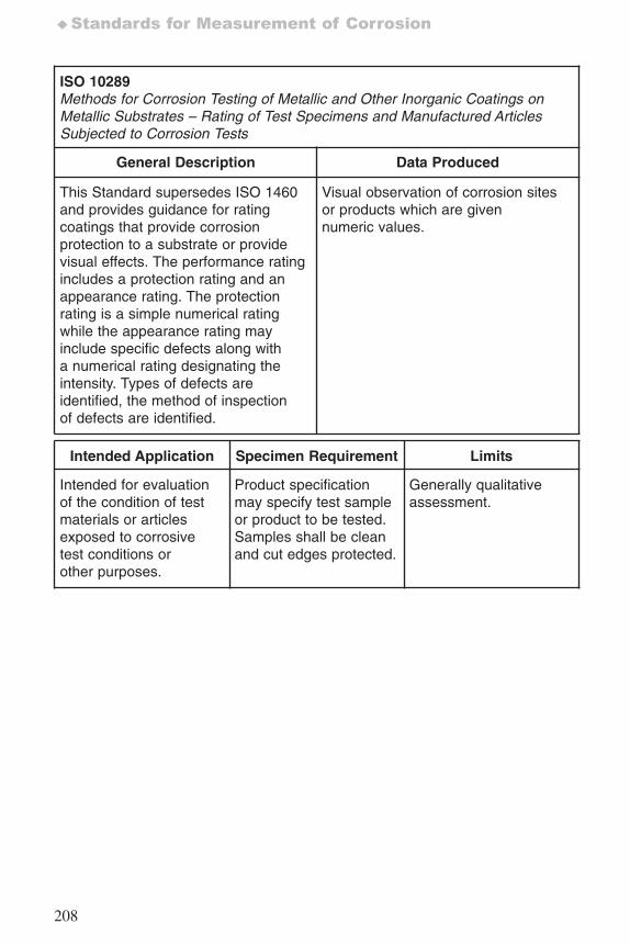
208
♦Standards for Measurement of Corrosion
ISO 10289Methods for Corrosion Testing of Metallic and Other Inorganic Coatings onMetallic Substrates – Rating of Test Specimens and Manufactured ArticlesSubjected to Corrosion Tests
General Description Data Produced
This Standard supersedes ISO 1460and provides guidance for ratingcoatings that provide corrosionprotection to a substrate or providevisual effects. The performance ratingincludes a protection rating and anappearance rating. The protectionrating is a simple numerical ratingwhile the appearance rating mayinclude specific defects along witha numerical rating designating theintensity. Types of defects areidentified, the method of inspectionof defects are identified.
Visual observation of corrosion sitesor products which are givennumeric values.
Intended Application Specimen Requirement Limits
Intended for evaluationof the condition of testmaterials or articlesexposed to corrosivetest conditions orother purposes.
Product specificationmay specify test sampleor product to be tested.Samples shall be cleanand cut edges protected.
Generally qualitativeassessment.
7652_.qxd 9/27/2005 11:58 AM Page 208
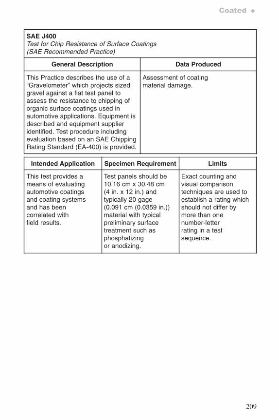
209
Coated ♦
SAE J400 Test for Chip Resistance of Surface Coatings (SAE Recommended Practice)
General Description Data Produced
This Practice describes the use of a “Gravelometer” which projects sizedgravel against a flat test panel toassess the resistance to chipping oforganic surface coatings used in automotive applications. Equipment isdescribed and equipment supplieridentified. Test procedure includingevaluation based on an SAE ChippingRating Standard (EA-400) is provided.
Assessment of coatingmaterial damage.
Intended Application Specimen Requirement Limits
This test provides ameans of evaluatingautomotive coatingsand coating systemsand has beencorrelated withfield results.
Test panels should be10.16 cm x 30.48 cm(4 in. x 12 in.) andtypically 20 gage(0.091 cm (0.0359 in.))material with typicalpreliminary surfacetreatment such asphosphatizingor anodizing.
Exact counting andvisual comparisontechniques are used toestablish a rating whichshould not differ bymore than onenumber-letterrating in a testsequence.
7652_.qxd 9/27/2005 11:58 AM Page 209
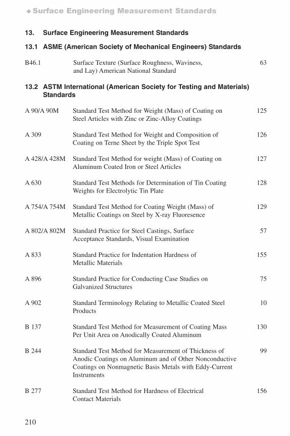
210
♦Surface Engineering Measurement Standards
13. Surface Engineering Measurement Standards
13.1 ASME (American Society of Mechanical Engineers) Standards
B46.1 Surface Texture (Surface Roughness, Waviness, 63and Lay) American National Standard
13.2 ASTM International (American Society for Testing and Materials)Standards
A 90/A 90M Standard Test Method for Weight (Mass) of Coating on 125Steel Articles with Zinc or Zinc-Alloy Coatings
A 309 Standard Test Method for Weight and Composition of 126Coating on Terne Sheet by the Triple Spot Test
A 428/A 428M Standard Test Method for weight (Mass) of Coating on 127Aluminum Coated Iron or Steel Articles
A 630 Standard Test Methods for Determination of Tin Coating 128Weights for Electrolytic Tin Plate
A 754/A 754M Standard Test Method for Coating Weight (Mass) of 129Metallic Coatings on Steel by X-ray Fluoresence
A 802/A 802M Standard Practice for Steel Castings, Surface 57Acceptance Standards, Visual Examination
A 833 Standard Practice for Indentation Hardness of 155Metallic Materials
A 896 Standard Practice for Conducting Case Studies on 75Galvanized Structures
A 902 Standard Terminology Relating to Metallic Coated Steel 10Products
B 137 Standard Test Method for Measurement of Coating Mass 130Per Unit Area on Anodically Coated Aluminum
B 244 Standard Test Method for Measurement of Thickness of 99Anodic Coatings on Aluminum and of Other Nonconductive Coatings on Nonmagnetic Basis Metals with Eddy-CurrentInstruments
B 277 Standard Test Method for Hardness of Electrical 156Contact Materials
7652_.qxd 9/27/2005 11:58 AM Page 210
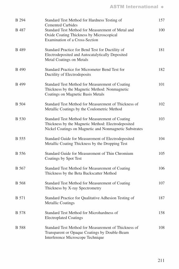
211
ASTM International ♦
B 294 Standard Test Method for Hardness Testing of 157Cemented Carbides
B 487 Standard Test Method for Measurement of Metal and 100Oxide Coating Thickness by Microscopical Examination of a Cross-Section
B 489 Standard Practice for Bend Test for Ductility of 181Electrodeposited and Autocatalytically Deposited Metal Coatings on Metals
B 490 Standard Practice for Micrometer Bend Test for 182Ductility of Electrodeposits
B 499 Standard Test Method for Measurement of Coating 101Thickness by the Magnetic Method: Nonmagnetic Coatings on Magnetic Basis Metals
B 504 Standard Test Method for Measurement of Thickness of 102Metallic Coatings by the Coulometric Method
B 530 Standard Test Method for Measurement of Coating 103Thickness by the Magnetic Method: Electrodeposited Nickel Coatings on Magnetic and Nonmagnetic Substrates
B 555 Standard Guide for Measurement of Electrodeposited 104Metallic Coating Thickness by the Dropping Test
B 556 Standard Guide for Measurement of Thin Chromium 105Coatings by Spot Test
B 567 Standard Test Method for Measurement of Coating 106Thickness by the Beta Backscatter Method
B 568 Standard Test Method for Measurement of Coating 107Thickness by X-ray Spectrometry
B 571 Standard Practice for Qualitative Adhesion Testing of 187Metallic Coatings
B 578 Standard Test Method for Microhardness of 158Electroplated Coatings
B 588 Standard Test Method for Measurement of Thickness of 108Transparent or Opaque Coatings by Double-Beam Interference Microscope Technique
7652_.qxd 9/27/2005 11:58 AM Page 211
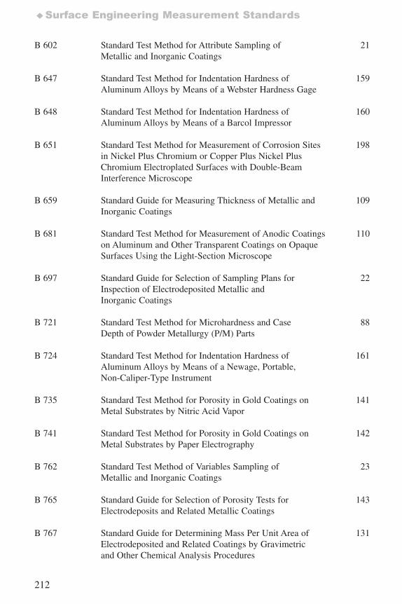
212
♦Surface Engineering Measurement Standards
B 602 Standard Test Method for Attribute Sampling of 21Metallic and Inorganic Coatings
B 647 Standard Test Method for Indentation Hardness of 159Aluminum Alloys by Means of a Webster Hardness Gage
B 648 Standard Test Method for Indentation Hardness of 160Aluminum Alloys by Means of a Barcol Impressor
B 651 Standard Test Method for Measurement of Corrosion Sites 198in Nickel Plus Chromium or Copper Plus Nickel PlusChromium Electroplated Surfaces with Double-Beam Interference Microscope
B 659 Standard Guide for Measuring Thickness of Metallic and 109Inorganic Coatings
B 681 Standard Test Method for Measurement of Anodic Coatings 110on Aluminum and Other Transparent Coatings on OpaqueSurfaces Using the Light-Section Microscope
B 697 Standard Guide for Selection of Sampling Plans for 22Inspection of Electrodeposited Metallic and Inorganic Coatings
B 721 Standard Test Method for Microhardness and Case 88Depth of Powder Metallurgy (P/M) Parts
B 724 Standard Test Method for Indentation Hardness of 161Aluminum Alloys by Means of a Newage, Portable, Non-Caliper-Type Instrument
B 735 Standard Test Method for Porosity in Gold Coatings on 141Metal Substrates by Nitric Acid Vapor
B 741 Standard Test Method for Porosity in Gold Coatings on 142Metal Substrates by Paper Electrography
B 762 Standard Test Method of Variables Sampling of 23 Metallic and Inorganic Coatings
B 765 Standard Guide for Selection of Porosity Tests for 143Electrodeposits and Related Metallic Coatings
B 767 Standard Guide for Determining Mass Per Unit Area of 131Electrodeposited and Related Coatings by Gravimetricand Other Chemical Analysis Procedures
7652_.qxd 9/27/2005 11:58 AM Page 212
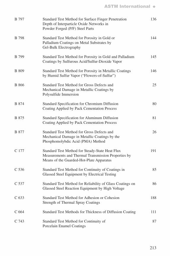
213
ASTM International ♦
B 797 Standard Test Method for Surface Finger Penetration 136Depth of Interparticle Oxide Networks in Powder Forged (P/F) Steel Parts
B 798 Standard Test Method for Porosity in Gold or 144Palladium Coatings on Metal Substrates by Gel-Bulk Electrography
B 799 Standard Test Method for Porosity in Gold and Palladium 145Coatings by Sulfurous Acid/Sulfur-Dioxide Vapor
B 809 Standard Test Method for Porosity in Metallic Coatings 146by Humid Sulfur Vapor (“Flowers-of-Sulfur”)
B 866 Standard Test Method for Gross Defects and 25Mechanical Damage in Metallic Coatings byPolysulfide Immersion
B 874 Standard Specification for Chromium Diffusion 80Coating Applied by Pack Cementation Process
B 875 Standard Specification for Aluminum Diffusion 81Coating Applied by Pack Cementation Process
B 877 Standard Test Method for Gross Defects and 26Mechanical Damage in Metallic Coatings by thePhosphomolybdic Acid (PMA) Method
C 177 Standard Test Method for Steady-State Heat Flux 191Measurements and Thermal Transmission Properties byMeans of the Guarded-Hot-Plate Apparatus
C 536 Standard Test Method for Continuity of Coatings in 85Glassed Steel Equipment by Electrical Testing
C 537 Standard Test Method for Reliability of Glass Coatings on 86Glassed Steel Reaction Equipment by High Voltage
C 633 Standard Test Method for Adhesion or Cohesion 188Strength of Thermal Spray Coatings
C 664 Standard Test Methods for Thickness of Diffusion Coating 111
C 743 Standard Test Method for Continuity of 87Porcelain Enamel Coatings
7652_.qxd 9/27/2005 11:58 AM Page 213
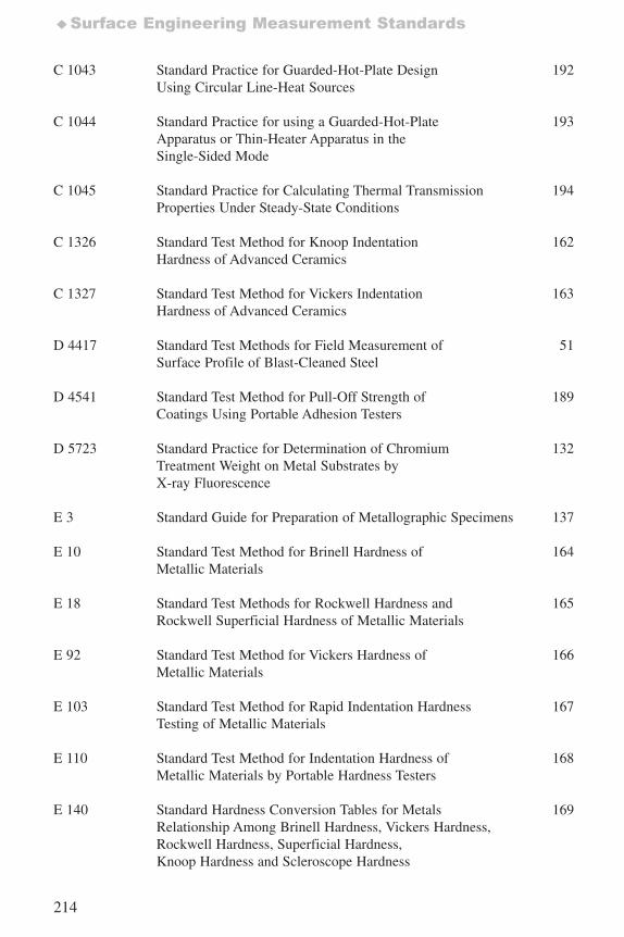
214
♦Surface Engineering Measurement Standards
C 1043 Standard Practice for Guarded-Hot-Plate Design 192Using Circular Line-Heat Sources
C 1044 Standard Practice for using a Guarded-Hot-Plate 193Apparatus or Thin-Heater Apparatus in theSingle-Sided Mode
C 1045 Standard Practice for Calculating Thermal Transmission 194Properties Under Steady-State Conditions
C 1326 Standard Test Method for Knoop Indentation 162Hardness of Advanced Ceramics
C 1327 Standard Test Method for Vickers Indentation 163Hardness of Advanced Ceramics
D 4417 Standard Test Methods for Field Measurement of 51Surface Profile of Blast-Cleaned Steel
D 4541 Standard Test Method for Pull-Off Strength of 189Coatings Using Portable Adhesion Testers
D 5723 Standard Practice for Determination of Chromium 132Treatment Weight on Metal Substrates byX-ray Fluorescence
E 3 Standard Guide for Preparation of Metallographic Specimens 137
E 10 Standard Test Method for Brinell Hardness of 164Metallic Materials
E 18 Standard Test Methods for Rockwell Hardness and 165Rockwell Superficial Hardness of Metallic Materials
E 92 Standard Test Method for Vickers Hardness of 166Metallic Materials
E 103 Standard Test Method for Rapid Indentation Hardness 167Testing of Metallic Materials
E 110 Standard Test Method for Indentation Hardness of 168Metallic Materials by Portable Hardness Testers
E 140 Standard Hardness Conversion Tables for Metals 169Relationship Among Brinell Hardness, Vickers Hardness, Rockwell Hardness, Superficial Hardness,Knoop Hardness and Scleroscope Hardness
7652_.qxd 9/27/2005 11:58 AM Page 214
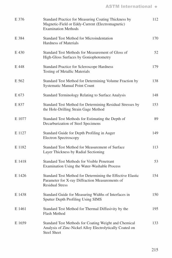
215
ASTM International ♦
E 376 Standard Practice for Measuring Coating Thickness by 112Magnetic-Field or Eddy-Current (Electromagnetic) Examination Methods
E 384 Standard Test Method for Microindentation 170Hardness of Materials
E 430 Standard Test Methods for Measurement of Gloss of 52High-Gloss Surfaces by Goniophotometry
E 448 Standard Practice for Scleroscope Hardness 179Testing of Metallic Materials
E 562 Standard Test Method for Determining Volume Fraction by 138Systematic Manual Point Count
E 673 Standard Terminology Relating to Surface Analysis 148
E 837 Standard Test Method for Determining Residual Stresses by 153the Hole-Drilling Strain Gage Method
E 1077 Standard Test Methods for Estimating the Depth of 89Decarburization of Steel Specimens
E 1127 Standard Guide for Depth Profiling in Auger 149Electron Spectroscopy
E 1182 Standard Test Method for Measurement of Surface 113Layer Thickness by Radial Sectioning
E 1418 Standard Test Methods for Visible Penetrant 53Examination Using the Water-Washable Process
E 1426 Standard Test Method for Determining the Effective Elastic 154Parameter for X-ray Diffraction Measurements ofResidual Stress
E 1438 Standard Guide for Measuring Widths of Interfaces in 150Sputter Depth Profiling Using SIMS
E 1461 Standard Test Method for Thermal Diffusivity by the 195Flash Method
E 1659 Standard Test Methods for Coating Weight and Chemical 133Analysis of Zinc-Nickel Alloy Electrolytically Coated onSteel Sheet
7652_.qxd 9/27/2005 11:58 AM Page 215
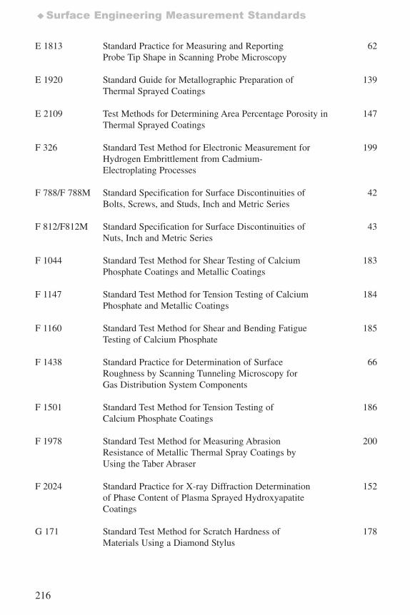
216
♦Surface Engineering Measurement Standards
E 1813 Standard Practice for Measuring and Reporting 62Probe Tip Shape in Scanning Probe Microscopy
E 1920 Standard Guide for Metallographic Preparation of 139Thermal Sprayed Coatings
E 2109 Test Methods for Determining Area Percentage Porosity in 147Thermal Sprayed Coatings
F 326 Standard Test Method for Electronic Measurement for 199Hydrogen Embrittlement from Cadmium-Electroplating Processes
F 788/F 788M Standard Specification for Surface Discontinuities of 42Bolts, Screws, and Studs, Inch and Metric Series
F 812/F812M Standard Specification for Surface Discontinuities of 43Nuts, Inch and Metric Series
F 1044 Standard Test Method for Shear Testing of Calcium 183Phosphate Coatings and Metallic Coatings
F 1147 Standard Test Method for Tension Testing of Calcium 184Phosphate and Metallic Coatings
F 1160 Standard Test Method for Shear and Bending Fatigue 185Testing of Calcium Phosphate
F 1438 Standard Practice for Determination of Surface 66Roughness by Scanning Tunneling Microscopy forGas Distribution System Components
F 1501 Standard Test Method for Tension Testing of 186Calcium Phosphate Coatings
F 1978 Standard Test Method for Measuring Abrasion 200Resistance of Metallic Thermal Spray Coatings byUsing the Taber Abraser
F 2024 Standard Practice for X-ray Diffraction Determination 152of Phase Content of Plasma Sprayed HydroxyapatiteCoatings
G 171 Standard Test Method for Scratch Hardness of 178Materials Using a Diamond Stylus
7652_.qxd 9/27/2005 11:58 AM Page 216
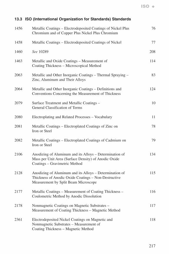
217
ISO ♦
13.3 ISO (International Organization for Standards) Standards
1456 Metallic Coatings – Electrodeposited Coatings of Nickel Plus 76Chromium and of Copper Plus Nickel Plus Chromium
1458 Metallic Coatings – Electrodeposited Coatings of Nickel 77
1460 See 10289 208
1463 Metallic and Oxide Coatings – Measurement of 114Coating Thickness – Microscopical Method
2063 Metallic and Other Inorganic Coatings – Thermal Spraying – 83Zinc, Aluminum and Their Alloys
2064 Metallic and Other Inorganic Coatings – Definitions and 124Conventions Concerning the Measurement of Thickness
2079 Surface Treatment and Metallic Coatings – 10General Classification of Terms
2080 Electroplating and Related Processes – Vocabulary 11
2081 Metallic Coatings – Electroplated Coatings of Zinc on 78Iron or Steel
2082 Metallic Coatings – Electroplated Coatings of Cadmium on 79Iron or Steel
2106 Anodizing of Aluminum and its Alloys – Determination of 134Mass per Unit Area (Surface Density) of Anodic OxideCoatings – Gravimetric Method
2128 Anodizing of Aluminum and its Alloys – Determination of 115Thickness of Anodic Oxide Coatings – Non-DestructiveMeasurement by Split Beam Microscope
2177 Metallic Coatings – Measurement of Coating Thickness – 116Coulometric Method by Anodic Dissolution
2178 Nonmagnetic Coatings on Magnetic Substrates – 117Measurement of Coating Thickness – Magnetic Method
2361 Electrodeposited Nickel Coatings on Magnetic and 118Nonmagnetic Substrates – Measurement ofCoating Thickness – Magnetic Method
7652_.qxd 9/27/2005 11:58 AM Page 217
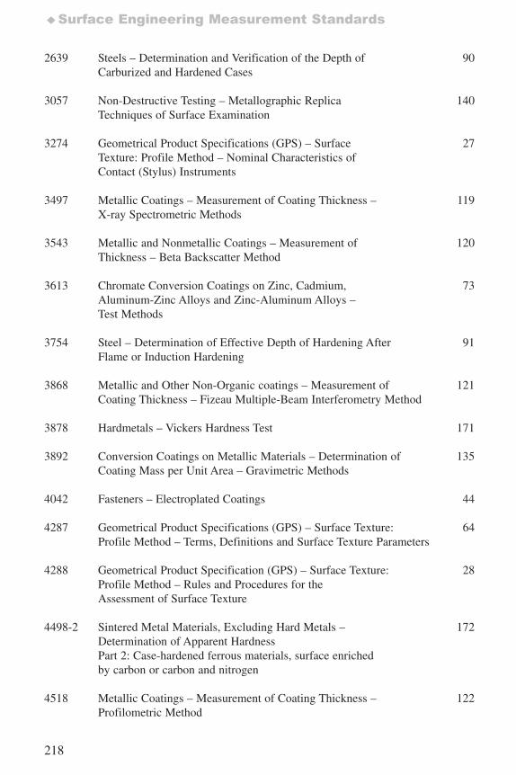
218
♦Surface Engineering Measurement Standards
2639 Steels – Determination and Verification of the Depth of 90Carburized and Hardened Cases
3057 Non-Destructive Testing – Metallographic Replica 140Techniques of Surface Examination
3274 Geometrical Product Specifications (GPS) – Surface 27Texture: Profile Method – Nominal Characteristics ofContact (Stylus) Instruments
3497 Metallic Coatings – Measurement of Coating Thickness – 119X-ray Spectrometric Methods
3543 Metallic and Nonmetallic Coatings – Measurement of 120Thickness – Beta Backscatter Method
3613 Chromate Conversion Coatings on Zinc, Cadmium, 73Aluminum-Zinc Alloys and Zinc-Aluminum Alloys – Test Methods
3754 Steel – Determination of Effective Depth of Hardening After 91Flame or Induction Hardening
3868 Metallic and Other Non-Organic coatings – Measurement of 121 Coating Thickness – Fizeau Multiple-Beam Interferometry Method
3878 Hardmetals – Vickers Hardness Test 171
3892 Conversion Coatings on Metallic Materials – Determination of 135Coating Mass per Unit Area – Gravimetric Methods
4042 Fasteners – Electroplated Coatings 44
4287 Geometrical Product Specifications (GPS) – Surface Texture: 64Profile Method – Terms, Definitions and Surface Texture Parameters
4288 Geometrical Product Specification (GPS) – Surface Texture: 28Profile Method – Rules and Procedures for the Assessment of Surface Texture
4498-2 Sintered Metal Materials, Excluding Hard Metals – 172Determination of Apparent Hardness Part 2: Case-hardened ferrous materials, surface enrichedby carbon or carbon and nitrogen
4518 Metallic Coatings – Measurement of Coating Thickness – 122Profilometric Method
7652_.qxd 9/27/2005 11:58 AM Page 218
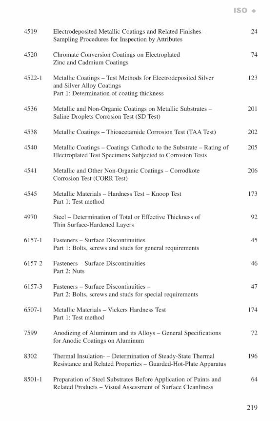
219
ISO ♦
4519 Electrodeposited Metallic Coatings and Related Finishes – 24Sampling Procedures for Inspection by Attributes
4520 Chromate Conversion Coatings on Electroplated 74Zinc and Cadmium Coatings
4522-1 Metallic Coatings – Test Methods for Electrodeposited Silver 123and Silver Alloy CoatingsPart 1: Determination of coating thickness
4536 Metallic and Non-Organic Coatings on Metallic Substrates – 201Saline Droplets Corrosion Test (SD Test)
4538 Metallic Coatings – Thioacetamide Corrosion Test (TAA Test) 202
4540 Metallic Coatings – Coatings Cathodic to the Substrate – Rating of 205Electroplated Test Specimens Subjected to Corrosion Tests
4541 Metallic and Other Non-Organic Coatings – Corrodkote 206Corrosion Test (CORR Test)
4545 Metallic Materials – Hardness Test – Knoop Test 173Part 1: Test method
4970 Steel – Determination of Total or Effective Thickness of 92Thin Surface-Hardened Layers
6157-1 Fasteners – Surface Discontinuities 45Part 1: Bolts, screws and studs for general requirements
6157-2 Fasteners – Surface Discontinuities 46Part 2: Nuts
6157-3 Fasteners – Surface Discontinuities – 47Part 2: Bolts, screws and studs for special requirements
6507-1 Metallic Materials – Vickers Hardness Test 174Part 1: Test method
7599 Anodizing of Aluminum and its Alloys – General Specifications 72for Anodic Coatings on Aluminum
8302 Thermal Insulation- – Determination of Steady-State Thermal 196Resistance and Related Properties – Guarded-Hot-Plate Apparatus
8501-1 Preparation of Steel Substrates Before Application of Paints and 64Related Products – Visual Assessment of Surface Cleanliness
7652_.qxd 9/27/2005 11:58 AM Page 219
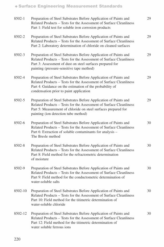
220
♦Surface Engineering Measurement Standards
8502-1 Preparation of Steel Substrates Before Application of Paints and 29Related Products – Tests for the Assessment of Surface CleanlinessPart 1: Field test for soluble iron corrosion products
8502-2 Preparation of Steel Substrates Before Application of Paints and 29Related Products – Tests for the Assessment of Surface Cleanliness Part 2: Laboratory determination of chloride on cleaned surfaces
8502-3 Preparation of Steel Substrates Before Application of Paints and 29Related Products – Tests for the Assessment of Surface Cleanliness Part 3: Assessment of dust on steel surfaces prepared for painting (pressure-sensitive tape method)
8502-4 Preparation of Steel Substrates Before Application of Paints and 29Related Products – Tests for the Assessment of Surface Cleanliness Part 4: Guidance on the estimation of the probability of condensation prior to paint application
8502-5 Preparation of Steel Substrates Before Application of Paints and 29Related Products – Tests for the Assessment of Surface Cleanliness Part 5: Measurement of chloride on steel surfaces prepared forpainting (ion detection tube method)
8502-6 Preparation of Steel Substrates Before Application of Paints and 30Related Products – Tests for the Assessment of Surface CleanlinessPart 6: Extraction of soluble contaminants for analysis – The Bresle method
8502-8 Preparation of Steel Substrates Before Application of Paints and 30Related Products – Tests for the Assessment of Surface CleanlinessPart 8: Field method for the refractometric determinationof moisture
8502-9 Preparation of Steel Substrates Before Application of Paints and 30Related Products – Tests for the Assessment of Surface CleanlinessPart 9: Field method for the conductometric determination ofwater-soluble salts
8502-10 Preparation of Steel Substrates Before Application of Paints and 30Related Products – Tests for the Assessment of Surface CleanlinessPart 10: Field method for the titimetric determination of water-soluble chloride
8502-12 Preparation of Steel Substrates Before Application of Paints and 30Related Products – Tests for the Assessment of Surface CleanlinessPart 12: Field method for the titimetric determination ofwater soluble ferrous ions
7652_.qxd 9/27/2005 11:58 AM Page 220
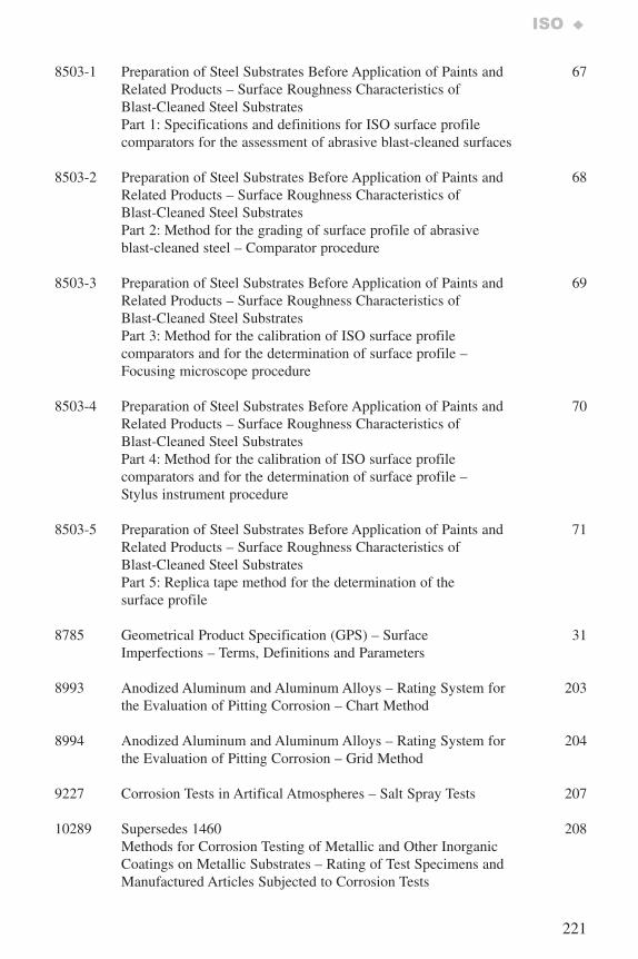
221
ISO ♦
8503-1 Preparation of Steel Substrates Before Application of Paints and 67Related Products – Surface Roughness Characteristics ofBlast-Cleaned Steel SubstratesPart 1: Specifications and definitions for ISO surface profilecomparators for the assessment of abrasive blast-cleaned surfaces
8503-2 Preparation of Steel Substrates Before Application of Paints and 68Related Products – Surface Roughness Characteristics ofBlast-Cleaned Steel SubstratesPart 2: Method for the grading of surface profile of abrasiveblast-cleaned steel – Comparator procedure
8503-3 Preparation of Steel Substrates Before Application of Paints and 69Related Products – Surface Roughness Characteristics ofBlast-Cleaned Steel SubstratesPart 3: Method for the calibration of ISO surface profilecomparators and for the determination of surface profile –Focusing microscope procedure
8503-4 Preparation of Steel Substrates Before Application of Paints and 70Related Products – Surface Roughness Characteristics ofBlast-Cleaned Steel SubstratesPart 4: Method for the calibration of ISO surface profilecomparators and for the determination of surface profile –Stylus instrument procedure
8503-5 Preparation of Steel Substrates Before Application of Paints and 71Related Products – Surface Roughness Characteristics ofBlast-Cleaned Steel SubstratesPart 5: Replica tape method for the determination of thesurface profile
8785 Geometrical Product Specification (GPS) – Surface 31Imperfections – Terms, Definitions and Parameters
8993 Anodized Aluminum and Aluminum Alloys – Rating System for 203the Evaluation of Pitting Corrosion – Chart Method
8994 Anodized Aluminum and Aluminum Alloys – Rating System for 204the Evaluation of Pitting Corrosion – Grid Method
9227 Corrosion Tests in Artifical Atmospheres – Salt Spray Tests 207
10289 Supersedes 1460 208Methods for Corrosion Testing of Metallic and Other Inorganic Coatings on Metallic Substrates – Rating of Test Specimens andManufactured Articles Subjected to Corrosion Tests
7652_.qxd 9/27/2005 11:58 AM Page 221
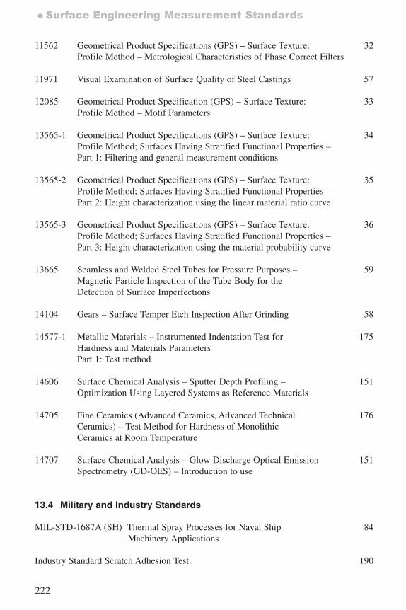
222
♦Surface Engineering Measurement Standards
11562 Geometrical Product Specifications (GPS) – Surface Texture: 32Profile Method – Metrological Characteristics of Phase Correct Filters
11971 Visual Examination of Surface Quality of Steel Castings 57
12085 Geometrical Product Specification (GPS) – Surface Texture: 33Profile Method – Motif Parameters
13565-1 Geometrical Product Specifications (GPS) – Surface Texture: 34Profile Method; Surfaces Having Stratified Functional Properties – Part 1: Filtering and general measurement conditions
13565-2 Geometrical Product Specifications (GPS) – Surface Texture: 35Profile Method; Surfaces Having Stratified Functional Properties –Part 2: Height characterization using the linear material ratio curve
13565-3 Geometrical Product Specifications (GPS) – Surface Texture: 36Profile Method; Surfaces Having Stratified Functional Properties – Part 3: Height characterization using the material probability curve
13665 Seamless and Welded Steel Tubes for Pressure Purposes – 59Magnetic Particle Inspection of the Tube Body for theDetection of Surface Imperfections
14104 Gears – Surface Temper Etch Inspection After Grinding 58
14577-1 Metallic Materials – Instrumented Indentation Test for 175Hardness and Materials ParametersPart 1: Test method
14606 Surface Chemical Analysis – Sputter Depth Profiling – 151Optimization Using Layered Systems as Reference Materials
14705 Fine Ceramics (Advanced Ceramics, Advanced Technical 176Ceramics) – Test Method for Hardness of MonolithicCeramics at Room Temperature
14707 Surface Chemical Analysis – Glow Discharge Optical Emission 151Spectrometry (GD-OES) – Introduction to use
13.4 Military and Industry Standards
MIL-STD-1687A (SH) Thermal Spray Processes for Naval Ship 84Machinery Applications
Industry Standard Scratch Adhesion Test 190
7652_.qxd 9/27/2005 11:58 AM Page 222
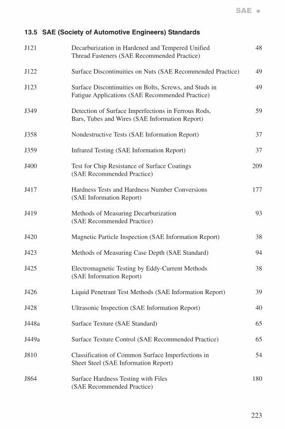
223
SAE ♦
13.5 SAE (Society of Automotive Engineers) Standards
J121 Decarburization in Hardened and Tempered Unified 48Thread Fasteners (SAE Recommended Practice)
J122 Surface Discontinuities on Nuts (SAE Recommended Practice) 49
J123 Surface Discontinuities on Bolts, Screws, and Studs in 49 Fatigue Applications (SAE Recommended Practice)
J349 Detection of Surface Imperfections in Ferrous Rods, 59Bars, Tubes and Wires (SAE Information Report)
J358 Nondestructive Tests (SAE Information Report) 37
J359 Infrared Testing (SAE Information Report) 37
J400 Test for Chip Resistance of Surface Coatings 209(SAE Recommended Practice)
J417 Hardness Tests and Hardness Number Conversions 177(SAE Information Report)
J419 Methods of Measuring Decarburization 93(SAE Recommended Practice)
J420 Magnetic Particle Inspection (SAE Information Report) 38
J423 Methods of Measuring Case Depth (SAE Standard) 94
J425 Electromagnetic Testing by Eddy-Current Methods 38 (SAE Information Report)
J426 Liquid Penetrant Test Methods (SAE Information Report) 39
J428 Ultrasonic Inspection (SAE Information Report) 40
J448a Surface Texture (SAE Standard) 65
J449a Surface Texture Control (SAE Recommended Practice) 65
J810 Classification of Common Surface Imperfections in 54Sheet Steel (SAE Information Report)
J864 Surface Hardness Testing with Files 180(SAE Recommended Practice)
7652_.qxd 9/27/2005 11:58 AM Page 223
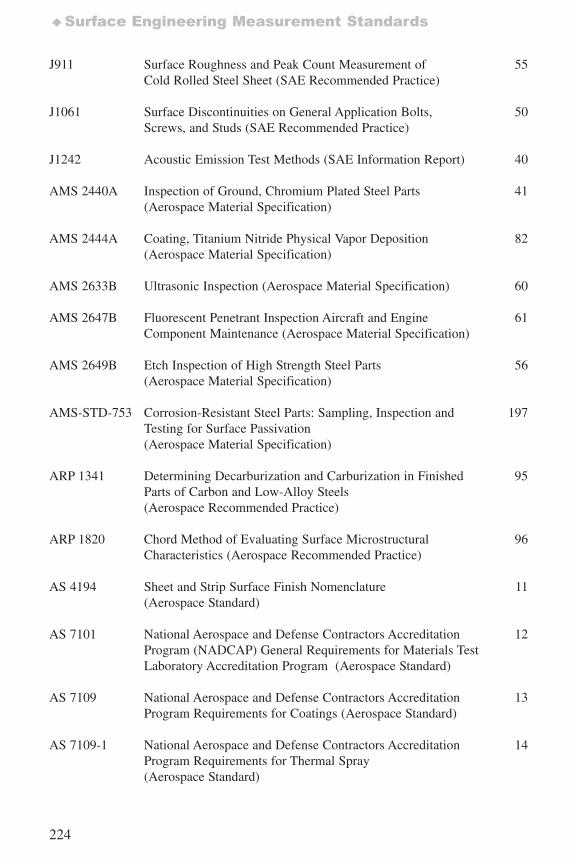
224
♦Surface Engineering Measurement Standards
J911 Surface Roughness and Peak Count Measurement of 55Cold Rolled Steel Sheet (SAE Recommended Practice)
J1061 Surface Discontinuities on General Application Bolts, 50Screws, and Studs (SAE Recommended Practice)
J1242 Acoustic Emission Test Methods (SAE Information Report) 40
AMS 2440A Inspection of Ground, Chromium Plated Steel Parts 41(Aerospace Material Specification)
AMS 2444A Coating, Titanium Nitride Physical Vapor Deposition 82(Aerospace Material Specification)
AMS 2633B Ultrasonic Inspection (Aerospace Material Specification) 60
AMS 2647B Fluorescent Penetrant Inspection Aircraft and Engine 61Component Maintenance (Aerospace Material Specification)
AMS 2649B Etch Inspection of High Strength Steel Parts 56(Aerospace Material Specification)
AMS-STD-753 Corrosion-Resistant Steel Parts: Sampling, Inspection and 197Testing for Surface Passivation(Aerospace Material Specification)
ARP 1341 Determining Decarburization and Carburization in Finished 95Parts of Carbon and Low-Alloy Steels (Aerospace Recommended Practice)
ARP 1820 Chord Method of Evaluating Surface Microstructural 96Characteristics (Aerospace Recommended Practice)
AS 4194 Sheet and Strip Surface Finish Nomenclature 11(Aerospace Standard)
AS 7101 National Aerospace and Defense Contractors Accreditation 12Program (NADCAP) General Requirements for Materials TestLaboratory Accreditation Program (Aerospace Standard)
AS 7109 National Aerospace and Defense Contractors Accreditation 13Program Requirements for Coatings (Aerospace Standard)
AS 7109-1 National Aerospace and Defense Contractors Accreditation 14Program Requirements for Thermal Spray(Aerospace Standard)
7652_.qxd 9/27/2005 11:58 AM Page 224
225
SAE ♦
AS 7109-2 National Aerospace and Defense Contractors Accreditation 15Program Requirements for Vapor Deposit (Aerospace Standard)
AS 7109-3 National Aerospace and Defense Contractors Accreditation 16Program Requirements for Cementation (Aerospace Standard)
AS 7109-4 National Aerospace and Defense Contractors Accreditation 17Program requirements for Stripping (Aerospace Standard)
AS 7109-5 National Aerospace and Defense Contractors Accreditation 18Program Requirements for Coating Evaluation Laboratory Practices (Aerospace Standard)
AS 7109-6 National Aerospace and Defense Contractors Accreditation 19Program Requirements for Plating of Coated Parts Laboratory Practices (Aerospace Standard)
AS 7109-7 National Aerospace and Defense Contractors Accreditation 20Program Requirements for Heat Treating for Suppliers of Coatings (Aerospace Standard)
7652_.qxd 9/27/2005 11:58 AM Page 225
226
♦Index
14. Index
Subject Standard PageA
Abrasion resistanceThermal spray metallic coatings ASTM F 1978 200
AccreditationCementation SAE AS 7109-3 16Coating evaluation laboratory practices SAE AS 7109-5 18Coating stripping SAE AS 7109-4 17Coating supplier SAE AS 7109 13Materials test laboratory SAE AS 7101 12Plating coated parts SAE AS 7109-6 19Thermal spray SAE AS 7109-1 14Vapor deposit SAE AS 7109-2 15
Acedic Acid Salt Solution (ACSS) ISO 9227 207
Adhesion testing of coatingsAdhesion strength ASTM C 633 188Grid test ISO 2063 83Portable testers ASTM D 4541 189Qualitative measurement ASTM B 571 187Paper Test ISO 3613 73Scribe (grid) ISO 2063 83Tape test SAE AMS 2444A 82
Aluminizing, See Aluminum diffusion coating
Aluminum Anodically coated,
mass measurement ASTM B 137 130Anodically coated,
specifications ISO 7599 72thickness measurement ASTM B 244 99
Transparent anodic coating thickness ASTM B 681 110
Aluminum diffusion coating Standard specification ASTM B 875 81 Supplier accreditation SAE AS 7109-3 16
Aluminum hardness Webster ASTM B 647 159Barcol Impressor ASTM B 648 160Newage non-caliper ASTM B 724 161
7652_.qxd 9/27/2005 11:58 AM Page 226
227
Index ♦
Aluminum-zinc coating Mass of, on steel ASTM A 754 129
Anodic coating Corrosion evaluation ISO 8993 203
ISO 8994 204ISO 9227 207
Mass ASTM B 137 130ISO 2106 134
Thickness ASTM B 244 99Transparent, thickness ASTM B 681 110
ISO 2128 115
Appearance rating, coatings ISO 10289 208ISO 4540 205
Attribute sampling, Metallic and inorganic coatings ASTM B 602 21
Auger electron spectroscopy (AES) ASTM E 1127 149
Autocatalytically deposited coatings, ductility of ASTM B 489 181
B
Bend testMetal coating ductility ASTM B 489 181Electrodeposited foil ductility ASTM B 490 182
Bendix test method, electrolytic tincoating weight ASTM A 630 128
Beta backscatter, coating thickness measurement ASTM B 567 106ISO 3543 120
Blast cleaned steel, See also Geometrical Product SpecificationSurface profile ISO 8503-2 71
Bond strength, See also Adhesion testing of coatingsThermal spray coatings ASTM C 633 188
Bresle methodfor extraction of soluble surface contaminants ISO 8502-6 30
Brinell hardness, See HardnessMetals ASTM E 10 164
7652_.qxd 9/27/2005 11:58 AM Page 227
228
♦Index
C
Cadmium coating, Thickness measurement ASTM B 555 104Hydrogen embrittlement from ASTM F 326 199
Calcium phosphate coatingShear testing ASTM F 1044 183Tension testing ASTM F 1147 184
ASTM F 1501 186Phase content by X-ray diffraction ASTM F 2024 152
Carburization Depth measurement SAE ARP 1341 95
ISO 2639 90
Case depth Powder metallurgy parts ASTM B 721 88Methods of measurement SAE J423 94Steel, carburized and hardened cases ISO 2639 90
ISO 3754 91ISO 4970 92
Case studies, galvanized structure ASTM A 896 75
Castings, steel, visual examination of surface quality ISO 11971 57
Cathodic coatings ISO 4540 205
Cemented carbides, hardness ASTM B 294 157
Ceramic, See also Calcium phosphate, HydroxyapatiteHardness, Knoop ASTM C 1326 162
ISO 14705 176Hardness, Vickers ASTM C 1327 163
ISO 14705 176
Chart method of corrosion evaluation ISO 8993 203
Chemical and compositional analysis, See also Surface analysisDepth profiling, AES ASTM E 1127 149Interface width using SIMS ASTM E 1438 150Terne sheet ASTM A 309 126Zinc-nickel on steel sheet, nickel by
Atomic absorption ASTM E 1659 133
7652_.qxd 9/27/2005 11:58 AM Page 228
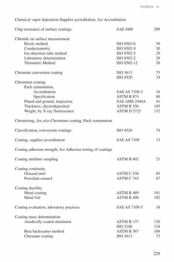
229
Index ♦
Chemical vapor deposition Supplier accreditation, See Accreditation
Chip resistance of surface coatings SAE J400 209
Chloride on surface measurementBresle method ISO 8502-6 30Conductometric ISO 8502-9 30Ion detection tube method ISO 8502-5 29Laboratory determination ISO 8502-2 29Titrimetric Method ISO 8502-12 30
Chromate conversion coating ISO 3613 73ISO 4520 74
Chromium coatingPack cementation,
Accreditation SAE AS 7109-3 16Specification ASTM B 874 80
Plated and ground, inspection SAE AMS 2440A 41Thickness, electrodeposited ASTM B 556 105Weight, by X-ray fluorescence ASTM D 5723 132
Chromizing, See also Chromium coating, Pack cementation
Classification, conversion coatings ISO 4520 74
Coating, supplier accreditation SAE AS 7109 13
Coating adhesion strength, See Adhesion testing of coatings
Coating attribute sampling ASTM B 602 21
Coating continuityGlassed steel ASTM C 536 85Porcelain enamel ASTM C 743 87
Coating ductility Metal coating ASTM B 489 181Metal foil ASTM B 490 182
Coating evaluation, laboratory practices SAE AS 7109-5 18
Coating mass determination Anodically coated aluminum ASTM B 137 130
ISO 2106 134Beta backscatter method ASTM B 567 106Chromate coating ISO 3613 73
7652_.qxd 9/27/2005 11:58 AM Page 229
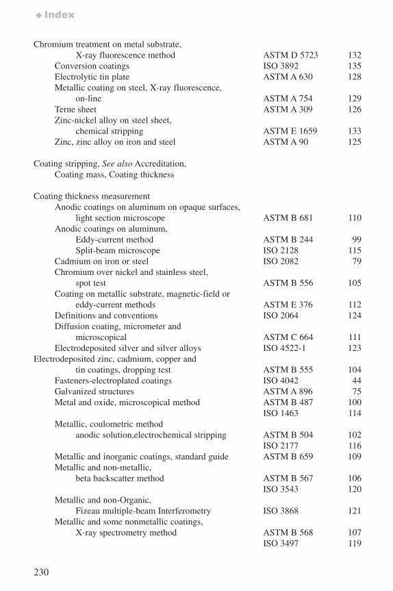
230
♦Index
Chromium treatment on metal substrate,X-ray fluorescence method ASTM D 5723 132
Conversion coatings ISO 3892 135Electrolytic tin plate ASTM A 630 128Metallic coating on steel, X-ray fluorescence,
on-line ASTM A 754 129Terne sheet ASTM A 309 126Zinc-nickel alloy on steel sheet,
chemical stripping ASTM E 1659 133Zinc, zinc alloy on iron and steel ASTM A 90 125
Coating stripping, See also Accreditation,Coating mass, Coating thickness
Coating thickness measurementAnodic coatings on aluminum on opaque surfaces,
light section microscope ASTM B 681 110Anodic coatings on aluminum,
Eddy-current method ASTM B 244 99Split-beam microscope ISO 2128 115
Cadmium on iron or steel ISO 2082 79Chromium over nickel and stainless steel,
spot test ASTM B 556 105Coating on metallic substrate, magnetic-field or
eddy-current methods ASTM E 376 112Definitions and conventions ISO 2064 124Diffusion coating, micrometer and
microscopical ASTM C 664 111Electrodeposited silver and silver alloys ISO 4522-1 123
Electrodeposited zinc, cadmium, copper andtin coatings, dropping test ASTM B 555 104
Fasteners-electroplated coatings ISO 4042 44Galvanized structures ASTM A 896 75Metal and oxide, microscopical method ASTM B 487 100
ISO 1463 114Metallic, coulometric method
anodic solution,electrochemical stripping ASTM B 504 102ISO 2177 116
Metallic and inorganic coatings, standard guide ASTM B 659 109Metallic and non-metallic,
beta backscatter method ASTM B 567 106ISO 3543 120
Metallic and non-Organic,Fizeau multiple-beam Interferometry ISO 3868 121
Metallic and some nonmetallic coatings,X-ray spectrometry method ASTM B 568 107
ISO 3497 119
7652_.qxd 9/27/2005 11:58 AM Page 230
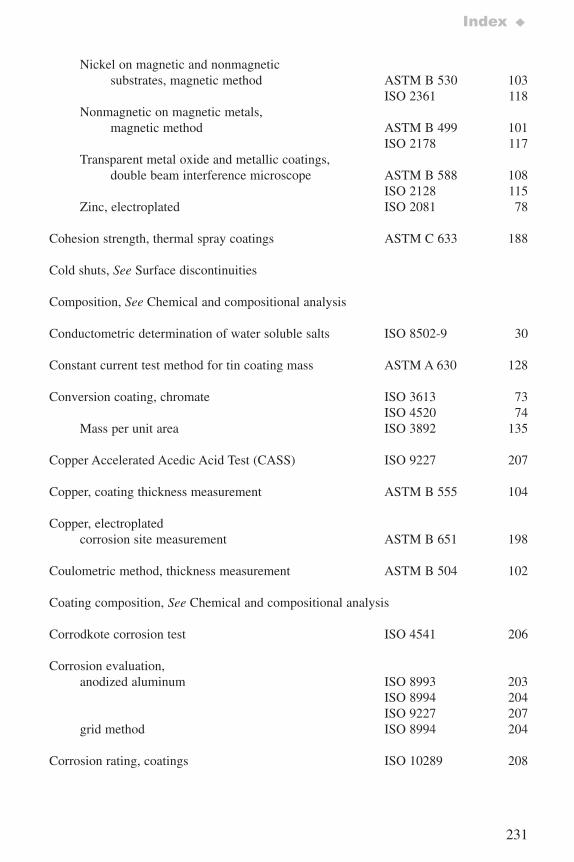
231
Index ♦
Nickel on magnetic and nonmagneticsubstrates, magnetic method ASTM B 530 103
ISO 2361 118Nonmagnetic on magnetic metals,
magnetic method ASTM B 499 101ISO 2178 117
Transparent metal oxide and metallic coatings,double beam interference microscope ASTM B 588 108
ISO 2128 115Zinc, electroplated ISO 2081 78
Cohesion strength, thermal spray coatings ASTM C 633 188
Cold shuts, See Surface discontinuities
Composition, See Chemical and compositional analysis
Conductometric determination of water soluble salts ISO 8502-9 30
Constant current test method for tin coating mass ASTM A 630 128
Conversion coating, chromate ISO 3613 73ISO 4520 74
Mass per unit area ISO 3892 135
Copper Accelerated Acedic Acid Test (CASS) ISO 9227 207
Copper, coating thickness measurement ASTM B 555 104
Copper, electroplatedcorrosion site measurement ASTM B 651 198
Coulometric method, thickness measurement ASTM B 504 102
Coating composition, See Chemical and compositional analysis
Corrodkote corrosion test ISO 4541 206
Corrosion evaluation,anodized aluminum ISO 8993 203
ISO 8994 204ISO 9227 207
grid method ISO 8994 204
Corrosion rating, coatings ISO 10289 208
7652_.qxd 9/27/2005 11:58 AM Page 231

232
♦Index
Corrosion site measurement, See also Electrography Electroplated surfaces ASTM B 651 198
Corrosion test,metallic substrates ISO 4536 201metallic coatings ISO 4538 202
ISO 4541 206ISO 10289 208
salt spray ISO 9227 207
Cracks, See Surface discontinuities
Crystallographic phase, See Phase content
D
Decarburization depthSteel ASTM E 1077 89Threaded fasteners SAE J121 48 Methods of measuring SAE J419 93
SAE ARP 1341 95
Depth profilingAuger electron spectroscopy ASTM E 1127 149
Depth of hardening, steel, flame orinduction hardened ISO 3754 91
Designation, electroplated coatings ISO 1456 76
Diffusion coating Aluminum specification ASTM B 875 81Chromium specification ASTM B 874 80Thickness measurement ASTM C 664 111
Dimensions, See also Coating thickness, Case depth, Decarburization depth, Surface roughness, Surface texture
DuctilityMetal coatings ASTM B 489 181Metal foils ASTM B 490 182
Dust, on steel ISO 8502-3 29
7652_.qxd 9/27/2005 11:58 AM Page 232
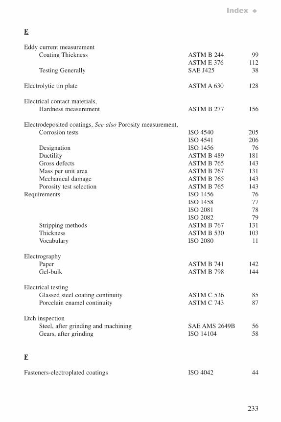
233
Index ♦
E
Eddy current measurement Coating Thickness ASTM B 244 99
ASTM E 376 112Testing Generally SAE J425 38
Electrolytic tin plate ASTM A 630 128
Electrical contact materials,Hardness measurement ASTM B 277 156
Electrodeposited coatings, See also Porosity measurement, Corrosion tests ISO 4540 205
ISO 4541 206Designation ISO 1456 76Ductility ASTM B 489 181Gross defects ASTM B 765 143Mass per unit area ASTM B 767 131Mechanical damage ASTM B 765 143Porosity test selection ASTM B 765 143
Requirements ISO 1456 76ISO 1458 77ISO 2081 78ISO 2082 79
Stripping methods ASTM B 767 131Thickness ASTM B 530 103Vocabulary ISO 2080 11
ElectrographyPaper ASTM B 741 142Gel-bulk ASTM B 798 144
Electrical testingGlassed steel coating continuity ASTM C 536 85Porcelain enamel continuity ASTM C 743 87
Etch inspection Steel, after grinding and machining SAE AMS 2649B 56Gears, after grinding ISO 14104 58
F
Fasteners-electroplated coatings ISO 4042 44
7652_.qxd 9/27/2005 11:58 AM Page 233
234
♦Index
Field testing and measurement, See also Case studies, PortableHardness testing, Replica
Adhesion, coating, portable testing ASTM D 4541 189Glassed steel coating continuity ASTM C 536 85Surface profile ASTM D 4417 51
Fizeau multiple-beam interferometry forcoating thickness ISO 3868 121
Flame hardening depth ISO 3754 91
Flash method for thermal diffusivity ASTM E 1461 195
Flowers of sulfur, coating porosity test ASTM B 809 146
Fluorescent penetrant inspection SAE AMS 2647B 61
G
Galvanized structures ASTM A 896 75
Gears, surface temper etch inspection after grinding ISO 14104 58
Gel-bulk electrography, for porosity measurement ASTM B 798 144
Geometrical product specification (GPS)Surface imperfections, terms,
definitions parameters ISO 8785 31Surface texture: profile method
Metrological characteristics ofphase correct filters ISO 11562 32
Motif parameters ISO 12085 33Rules and procedures for
assessment of texture ISO 4288 28Stylus characteristics ISO 3274 27Terms, definitions, surface
texture parameters ISO 4287 64Surfaces having stratified functional properties-
Part 1-filtering and generalmeasurement conditions ISO 13565-1 34
Part 2- height characterization usinglinear material ratio curve ISO 13565-2 35
Part 3- height characterization usingthe material probability curve ISO 13565-3 36
7652_.qxd 9/27/2005 11:58 AM Page 234
235
Index ♦
Glassed steelCoating continuity ASTM C 536 85Reliability by high voltage ASTM C 537 86
Gloss measurement by goniophotometry ASTM E 430 52
Gold coating, porosity tests ASTM B 735 141ASTM B 741 142ASTM B 798 144ASTM B 799 145
Goniophotometry, for gloss measurement ASTM E 430 52
Gouges, See Surface discontinuities
Grid method of corrosion evaluation ISO 8994 204
Grinding damage, chromium plated steel SAE AMS 2440A 41
Gross defects in coatings, test for ASTM B 765 143ASTM B 866 25ASTM B 877 26
Guarded hot plate ASTM C 177 191
H
Hardness Carburization SAE ARP1341 95Conversion tables, metallic materials ASTM E 140 169
SAE J417 177Decarburization measurement SAE J419 93
SAE ARP1341 95Method
Barcol Impressor, aluminum alloys ASTM B 648 160Brinell, metallic materials ASTM E 10 164Files, testing with SAE J864 180Instrumented ISO 14577 175Knoop
Advanced ceramics ASTM C 1326 162ISO 14705 176
Electroplated coatings ASTM B 578 158Metallic materials ISO 4545 173
Martens ISO 14577 175 Microindentation ASTM E 384 170
7652_.qxd 9/27/2005 11:58 AM Page 235
236
♦Index
Newage non-caliper type, aluminum alloys ASTM B 724 161Portable indentation, metallic materials ASTM E 110 168Rapid indentation, metallic materials ASTM E 103 167Rockwell
Cemented carbides ASTM B 294 157Electrical contact materials ASTM B 277 156Metallic materials ASTM E 18 165
Superficial, metallic materials ASTM E 18 165Scleroscope, metallic materials ASTM E 448 179Scratch ASTM G 171 178Vickers
Advanced ceramics ASTM C 1327 163ISO 14705 176
Hard metals ISO 3878 171Metallic materials ASTM E 92 166Metallic materials, method ISO 6507-1 174
Webster Hardness Gage, aluminum alloys ASTM B 647 159
Hole drilling, residual stress analysis ASTM E 837 153
Humid sulfur vapor porosity test ASTM B 809 146
Hydrogen embrittlement, from cadmium electroplating ASTM F 326 199
Hydrogen detection, in cadmium electroplating ASTM F 326 199
Hydroxyapitite, see calcium phosphatePhase content by X-ray diffraction ASTM F 2024 152
I
Indentation hardness, See Hardness
Induction hardening, steel ISO 3754 91
Infrared testing SAE J359 37
Inspection Electrodeposited coatings, inspection
by attributes ISO 4519 24 Etch of high strength steel parts SAE AMS 2649B 56Metallic and inorganic coatings,
attribute sampling ASTM B 602 21Metallic and inorganic coatings,
sampling plan selection ASTM B 697 22
7652_.qxd 9/27/2005 11:58 AM Page 236
237
Index ♦
Instrumented Indentation Hardness, See Hardness
Interference microscope ASTM B 588 108
Interferometry, Fizeau ISO 3868 121
Interparticle oxide networks, powder forged steel ASTM B 797 136
Ion detection tube, for measurement of chloride ISO 8502-5 29
Ion sputtering ASTM E 1127 149
K
Knoop hardness, See Hardness
L
Laps, See Surface discontinuities
Lay, See Surface texture
Lead-tin coating ASTM A 309 126
Liquid penetrant testing ASTM E 1418 53SAE J426 39
M
Magnetic method, coating thickness ASTM B 499 101ASTM E 376 112
Magnetic particle inspection Discontinuities SAE J420 38Steel tube imperfections ISO 13665 59
Martens Hardness, See Hardness
Mass per unit area, See Coating mass measurementGravimetric procedure ASTM B 767 131
7652_.qxd 9/27/2005 11:58 AM Page 237
238
♦Index
Mechanical damage of coatings, tests for ASTM B 765 143ASTM B 866 25ASTM B 877 26
Metallic coatings terminology ASTM A 902 10
Metallographic specimen preparation General ASTM E 3 137Replica techniques ISO 3057 140Thermal spray coatings ASTM E 1920 139
MicrohardnessDecarburization measurement,
threaded fasteners SAE J121 48Electroplated coatings ASTM B 578 158Microindentation hardness ASTM E 384 170Powder metallurgy parts case depth ASTM B 721 88Surface hardened layer thickness ISO 4970 92
Microscopical measurement, thickness ASTM B 487 100
Microstructure, See also Metallographic specimen preparationArea percentage porosity,
thermal spray coatings ASTM E 2109 147Chord method for surface microstructure SAE ARP1820 96Decarburization depth, steel ASTM E 1077 89
SAE J419 93SAE ARP1341 95
Decarburization measurement, threaded fasteners SAE J121 48
Metallographic preparation,thermal spray coatings ASTM E 1920 139
Point count analysis ASTM E 562 138Replica techniques ISO 3057 140Surface hardened layer thickness ISO 4970 92Volume fraction determination ASTM E 562 138
Moisture,Condensation on steel ISO 8502-4 29Refractometric determination ISO 8502-8 30
N
NADCAP (National Aerospace and Defense ContractorsAccreditation Program), See Accreditation
7652_.qxd 9/27/2005 11:58 AM Page 238
239
Index ♦
Neutral Salt Solution (NSS) ISO 9227 207
Nickel, electrodepositedCoating thickness ASTM B 530 103Corrosion site measurement ASTM B 651 198Requirements ISO 1458 77
Nicks, See Surface discontinuities
Nitric acid vapor test for porosity ASTM B 735 141
NomenclatureSheet and strip surface finish SAE AS 4194 11
Nondestructive examination (NDE)Acoustic emission SAE J1242 40Fluorescent penetrant SAE AMS 2647B 61Infrared testing SAE J359 37Magnetic particle inspection SAE J420 38
ISO 13665 59Nondestructive tests SAE J358 37Surface defects by visible penetrants ASTM E 1418 53
SAE J426 39Ultrasonic inspection SAE J428 40
Nonmagnetic coating thickness measurement ASTM B 499 101
Nonmetallic coating thickness measurement ASTM B 567 106ASTM B 568 107
O
On-line coating mass measurement ASTM A 754 129
Oxide coating thickness ASTM B 487 100ISO 1463 114
Oxide finger penetration, powder forged steel ASTM B 797 136
P
Pack cementationAluminum, specification ASTM B 875 81Chromium, specification ASTM B 874 80Supplier accreditation SAE AS 7109-3 16
7652_.qxd 9/27/2005 11:58 AM Page 239
240
♦Index
Paint, chip resistance SAE J400 209
Painted steel ISO 8502 29
Palladium coatingPorosity ASTM B 798 144
ASTM B 799 145
Paper electrography for porosity measurement ASTM B 741 142
Performance rating, coating ISO 10289 208
Phase content, hydroxyapatite ASTM F 2024 152
Physical vapor depositionCoating thickness
Profilometry ISO 4518 122Radial sectioning ASTM E 1182 113Supplier accreditation SAE AS 7109-2 15X-ray spectroscopy ISO 3497 119
Pitting corrosion evaluation, anodized aluminum ISO 8993 203ISO 8994 204
Plating porosity, See Porosity
Plating supplier accreditation SAE AS 7109-6 19
Phosphomolybdic acid (PMA) test B 877 26
Pits, See Surface discontinuities
Point count, systematic, microstructural analysis E 562 138
Polysulfide immersion test B 866 25
PorosityFlowers of sulfur method ASTM B 809 146Gold coatings, nitric acid vapor ASTM B 735 141Gold coatings, paper electrography ASTM B 741 142Gold and palladium coatings,
gel-bulk electrography ASTM B 798 144humid sulfur vapor method ASTM B 809 146phosphomolybdic acid, (PMA) method ASTM B 877 26polysulfide immersion method ASTM B 866 25sulfurous acid/sulfur-dioxide vapor ASTM B 799 145surface, isolated, visible penetrant examination ASTM E 1418 53
7652_.qxd 9/27/2005 11:58 AM Page 240
241
Index ♦
test selection for coatings ASTM B 765 143thermal spray coatings, area percentage ASTM E 2109 147
Pore corrosion test ASTM B 735 141ASTM B 799 145ASTM B 809 146
Portable hardness testing Barcol Impressor ASTM B 648 160Indentation ASTM E 110 168Newage non-caliper ASTM B 724 161Webster ASTM B 647 159
Powder metallurgy partsCase depth ASTM B 721 88Oxide finger penetration ASTM B 797 136
Protection rating, coating ISO 10289 208
Pull-off strength, See Adhesion testing
R
Rapid indentation hardness, See HardnessMetallic materials ASTM E 103 167
ReliabilityGlass coatings on steel ASTM C 537 86
ReplicaSurface profile measurement ASTM D 4417 51Metallographic examination ISO 3057 140
Reflection, See Gloss
Residual stressHole-drilling strain-gage method ASTM E 837 153X-ray diffraction method, effective elastic parameter ASTM E 1426 154
Rockwell, See Hardness
Roughness, See Surface texture
7652_.qxd 9/27/2005 11:58 AM Page 241
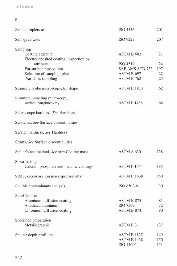
242
♦Index
S
Saline droplets test ISO 4536 201
Salt spray tests ISO 9227 207
SamplingCoating attribute ASTM B 602 21Electrodeposited coating, inspection by
attribute ISO 4519 24For surface passivation SAE AMS-STD-753 197Selection of sampling plan ASTM B 697 22Variables sampling ASTM B 762 23
Scanning probe microscopy, tip shape ASTM E 1813 62
Scanning tunneling microscopy, surface roughness by ASTM F 1438 66
Scleroscope hardness, See Hardness
Scratches, See Surface discontinuities
Scratch hardness, See Hardness
Seams, See Surface discontinuities
Stellar’s test method, See also Coating mass ASTM A 630 128
Shear testingCalcium phosphate and metallic coatings ASTM F 1044 183
SIMS, secondary ion mass spectrometry ASTM E 1438 150
Soluble contaminants analysis ISO 8502-6 30
SpecificationsAluminum diffusion coating ASTM B 875 81Anodized aluminum ISO 7599 72Chromium diffusion coating ASTM B 874 80
Specimen preparation Metallographic ASTM E 3 137
Sputter depth profiling ASTM E 1127 149ASTM E 1438 150ISO 14606 151
7652_.qxd 9/27/2005 11:58 AM Page 242
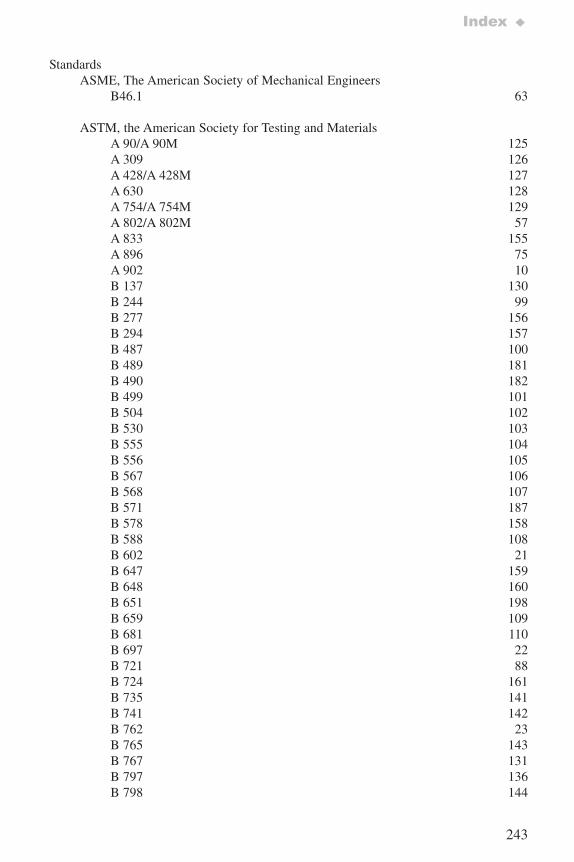
243
Index ♦
StandardsASME, The American Society of Mechanical Engineers
B46.1 63
ASTM, the American Society for Testing and MaterialsA 90/A 90M 125A 309 126A 428/A 428M 127A 630 128A 754/A 754M 129A 802/A 802M 57A 833 155A 896 75A 902 10 B 137 130B 244 99B 277 156B 294 157B 487 100B 489 181B 490 182B 499 101B 504 102B 530 103B 555 104B 556 105B 567 106B 568 107B 571 187B 578 158B 588 108B 602 21B 647 159B 648 160B 651 198B 659 109B 681 110B 697 22B 721 88B 724 161B 735 141B 741 142B 762 23B 765 143B 767 131B 797 136B 798 144
7652_.qxd 9/27/2005 11:58 AM Page 243
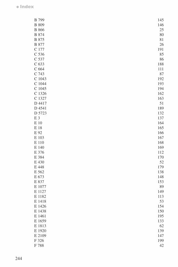
244
♦Index
B 799 145B 809 146B 866 25B 874 80B 875 81B 877 26C 177 191C 536 85C 537 86C 633 188C 664 111C 743 87C 1043 192C 1044 193C 1045 194C 1326 162C 1327 163D 4417 51D 4541 189D 5723 132E 3 137E 10 164E 18 165E 92 166E 103 167E 110 168E 140 169E 376 112E 384 170E 430 52E 448 179E 562 138E 673 148E 837 153E 1077 89E 1127 149E 1182 113E 1418 53E 1426 154E 1438 150E 1461 195E 1659 133E 1813 62E 1920 139E 2109 147F 326 199F 788 42
7652_.qxd 9/27/2005 11:58 AM Page 244
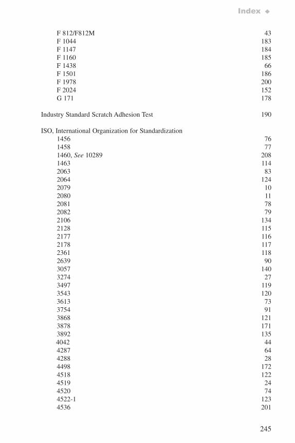
245
Index ♦
F 812/F812M 43F 1044 183F 1147 184F 1160 185F 1438 66F 1501 186F 1978 200F 2024 152G 171 178
Industry Standard Scratch Adhesion Test 190
ISO, International Organization for Standardization1456 761458 771460, See 10289 2081463 1142063 832064 1242079 102080 112081 782082 79 2106 1342128 1152177 1162178 1172361 1182639 903057 1403274 273497 1193543 1203613 733754 913868 1213878 1713892 1354042 444287 644288 284498 1724518 1224519 244520 744522-1 1234536 201
7652_.qxd 9/27/2005 11:58 AM Page 245
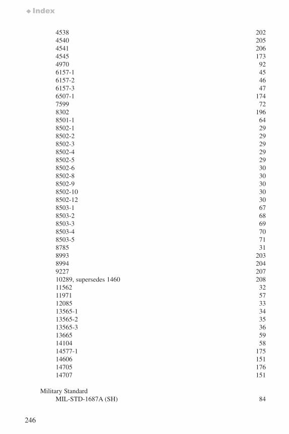
246
♦Index
4538 2024540 2054541 2064545 1734970 926157-1 456157-2 466157-3 476507-1 1747599 728302 1968501-1 648502-1 298502-2 298502-3 298502-4 298502-5 298502-6 308502-8 308502-9 308502-10 308502-12 308503-1 678503-2 688503-3 698503-4 708503-5 718785 318993 2038994 2049227 20710289, supersedes 1460 20811562 3211971 5712085 3313565-1 3413565-2 3513565-3 3613665 5914104 5814577-1 17514606 15114705 17614707 151
Military StandardMIL-STD-1687A (SH) 84
7652_.qxd 9/27/2005 11:58 AM Page 246
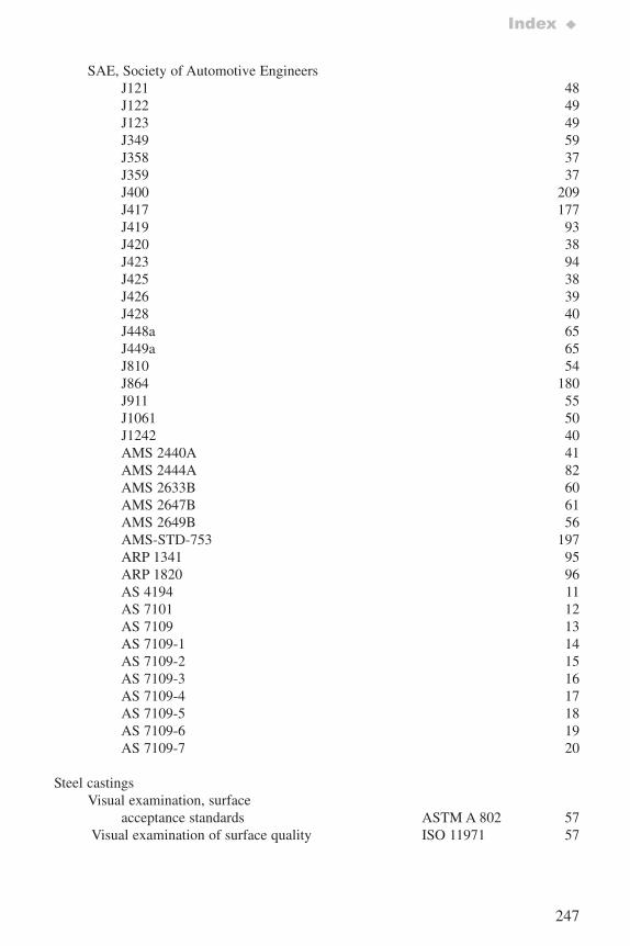
247
Index ♦
SAE, Society of Automotive EngineersJ121 48J122 49J123 49J349 59J358 37J359 37J400 209J417 177J419 93J420 38J423 94J425 38J426 39J428 40J448a 65J449a 65J810 54J864 180J911 55J1061 50J1242 40AMS 2440A 41AMS 2444A 82AMS 2633B 60AMS 2647B 61AMS 2649B 56AMS-STD-753 197ARP 1341 95ARP 1820 96AS 4194 11AS 7101 12AS 7109 13AS 7109-1 14AS 7109-2 15AS 7109-3 16 AS 7109-4 17AS 7109-5 18AS 7109-6 19AS 7109-7 20
Steel castingsVisual examination, surface
acceptance standards ASTM A 802 57Visual examination of surface quality ISO 11971 57
7652_.qxd 9/27/2005 11:58 AM Page 247
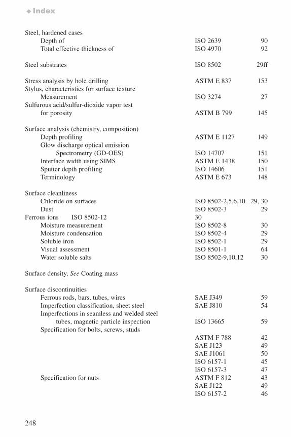
248
♦Index
Steel, hardened cases Depth of ISO 2639 90Total effective thickness of ISO 4970 92
Steel substrates ISO 8502 29ff
Stress analysis by hole drilling ASTM E 837 153Stylus, characteristics for surface texture
Measurement ISO 3274 27 Sulfurous acid/sulfur-dioxide vapor test
for porosity ASTM B 799 145
Surface analysis (chemistry, composition)Depth profiling ASTM E 1127 149Glow discharge optical emission
Spectrometry (GD-OES) ISO 14707 151Interface width using SIMS ASTM E 1438 150Sputter depth profiling ISO 14606 151Terminology ASTM E 673 148
Surface cleanlinessChloride on surfaces ISO 8502-2,5,6,10 29, 30Dust ISO 8502-3 29
Ferrous ions ISO 8502-12 30Moisture measurement ISO 8502-8 30Moisture condensation ISO 8502-4 29Soluble iron ISO 8502-1 29Visual assessment ISO 8501-1 64Water soluble salts ISO 8502-9,10,12 30
Surface density, See Coating mass
Surface discontinuitiesFerrous rods, bars, tubes, wires SAE J349 59Imperfection classification, sheet steel SAE J810 54Imperfections in seamless and welded steel
tubes, magnetic particle inspection ISO 13665 59Specification for bolts, screws, studs
ASTM F 788 42SAE J123 49SAE J1061 50ISO 6157-1 45ISO 6157-3 47
Specification for nuts ASTM F 812 43SAE J122 49ISO 6157-2 46
7652_.qxd 9/27/2005 11:58 AM Page 248
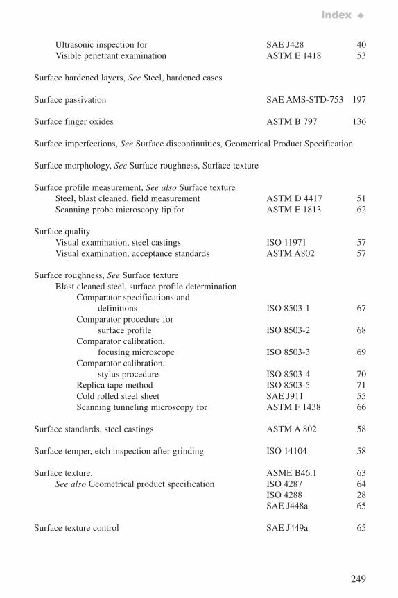
249
Index ♦
Ultrasonic inspection for SAE J428 40Visible penetrant examination ASTM E 1418 53
Surface hardened layers, See Steel, hardened cases
Surface passivation SAE AMS-STD-753 197
Surface finger oxides ASTM B 797 136
Surface imperfections, See Surface discontinuities, Geometrical Product Specification
Surface morphology, See Surface roughness, Surface texture
Surface profile measurement, See also Surface textureSteel, blast cleaned, field measurement ASTM D 4417 51Scanning probe microscopy tip for ASTM E 1813 62
Surface qualityVisual examination, steel castings ISO 11971 57Visual examination, acceptance standards ASTM A802 57
Surface roughness, See Surface texture Blast cleaned steel, surface profile determination
Comparator specifications anddefinitions ISO 8503-1 67
Comparator procedure for surface profile ISO 8503-2 68
Comparator calibration, focusing microscope ISO 8503-3 69
Comparator calibration, stylus procedure ISO 8503-4 70
Replica tape method ISO 8503-5 71Cold rolled steel sheet SAE J911 55Scanning tunneling microscopy for ASTM F 1438 66
Surface standards, steel castings ASTM A 802 58
Surface temper, etch inspection after grinding ISO 14104 58
Surface texture, ASME B46.1 63See also Geometrical product specification ISO 4287 64
ISO 4288 28SAE J448a 65
Surface texture control SAE J449a 65
7652_.qxd 9/27/2005 11:58 AM Page 249
250
♦Index
T
Tape, pressure sensitive for dust on steel ISO 8502-3 29
Terminology, General classification of terms ISO 2079 10Metallic coatings ASTM A 902 10Sheet and strip surface finish SAE AS4194 11Surface analysis ASTM E 673 148Vocabulary, electroplating ISO 2080 11
Tension testingCalcium phosphate and metallic coatings ASTM F 1147 184Calcium phosphate coatings ASTM F 1501 186
Terne sheet, See Coating mass measurement
Texture, See Surface profile, Surface texture
Thermal conductivity ASTM C 177 191ASTM C 1043 192
Thermal diffusivity ASTM E 1461 195
Thermal resistance ASTM C 177 191ASTM C 1043 192ASTM C 1044 193ASTM C 1045 194ISO 8302 196
Thermal spray coatings Abrasion resistance, Taber Abraser ASTM F 1978 200Adhesion/cohesion measurement ASTM C 633 188Metallographic preparation ASTM E 1920 139Military standard MIL-STD-1687A(SH) 84Percentage porosity determination ASTM E 2109 147Phase content, hydroxyapatite ASTM F 2024 152Supplier accreditation, See AccreditationZinc, aluminum and their alloys ISO 2063 83
Thickness, See Coating thickness
Thioacetamide corrosion test (TAA) ISO 4538 202
Tin coating, mass measurement ASTM A 754 129
Tin plate, mass measurement ASTM A 630 128
7652_.qxd 9/27/2005 11:58 AM Page 250
251
Index ♦
Titanium nitride,physical vapor deposition specification SAE AMS 2444A 82
Titration test method for coating mass ASTM A 630 128
Titrimetric determination Ferrous ions ISO 8502-12 30Chloride ISO 8502-10 30
Triple spot test for coating mass ASTM A 309 126
U
Ultrasonic inspection for surface discontinuities SAE J428 40
V
Variables sampling of metallic and inorganic coatings ASTM B 762 23
Vickers hardnessAdvanced ceramics ASTM C 1327 163Metallic materials ASTM E 92 166Hard metals ISO 3878 171Test method ISO 6507-1 174
Visual inspection, Surface, steel castings ASTM A 802 57Comparison, surface profile ASTM D 4417 51
Vocabulary, See Terminology
Volume fraction, microstructural constituent ASTM E 562 138
W
Waviness, See Surface texture
Webster Hardness Gage ASTM B 647 159
7652_.qxd 9/27/2005 11:58 AM Page 251
X
X-ray diffractionEffective elastic parameter for residual
stress measurement ASTM E 1426 154Phase content, hydroxyapatite ASTM F 2024 152
X-ray fluorescence Mass of metallic coating on steel ASTM A 754 129Coating thickness by X-ray spectrometry ISO 3497 119Chromium treatment weight ASTM D5723 132
X-ray spectrometry, Coating thickness measurement ASTM B 568 107
ISO 3497 119Coating mass measurement by
X-ray fluoresence ASTM A 754 129
Z
Zinc, zinc alloys on steel Mass, acid stripping ASTM A 90 125Mass, X-ray fluorescence ASTM A 754 129Mass, composition ASTM E 1659 133Specifications ISO 2081 78Thermal spray ISO 2063 83
Thickness ASTM B 555 104
252
♦Index
7652_.qxd 9/27/2005 11:58 AM Page 252

7652_CVR.qxd 9/27/2005 11:56 AM Page 2

April 2005
Stanley J. Dapkunas
960-9
Surface EngineeringMeasurementStandards forInorganic Materials
SP 960-9 • Surface En
gin
eering
Measu
remen
t Stand
ards fo
r Ino
rgan
ic Materials
NI
ST
r
ec
om
me
nd
ed
p r a c t i c e g u i d e
SpecialPublication
960-9
NNaattiioonnaall IInnssttiittuuttee ooffSSttaannddaarrddss aanndd TTeecchhnnoollooggyyTechnology AdministrationU.S. Department of Commerce
7652_CVR.qxd 9/27/2005 11:56 AM Page 1