Standards Document - OpenCircuits · Standards Document 1-Wire ... COLOR CODING.....14 LABELING OF...
28
SPRINGBOK DIGITRONICS Innovative Hardware and Software for the modern world Standards Document S S t t a a n n d d a a r r d d s s D D o o c c u u m m e e n n t t 1-Wire REF R R E E F F Springbok Digitronics Subject: Page 0 of 1
Transcript of Standards Document - OpenCircuits · Standards Document 1-Wire ... COLOR CODING.....14 LABELING OF...

SPRINGBOK DIGITRONICS Innovative Hardware and Software for the modern world
Standards Document SSttaannddaarrddss DDooccuummeenntt
1-Wire
REF RREEFF
Springbok Digitronics Subject: Page 0 of 1
I N N O V A T I V E H A R D W A R E A N D S O F T W A R E
An 1-Wire™ Series Guide
Format of this Document
Use of Icons: Through out this document you will find various help icons. By clicking on the icon you will be linked to information about each category of information. Valuable information may include links to datasheets, manuals and other reference material. Contact information is assumed to be names and addresses of people and companies. Internet links are hyperlinks to reference documents available on the Internet, quite often they are original sources for public information like data sheets. Always consult these links for the latest information from other companies. Application
notes are written by Springbok Digitronics in order to ease the understanding and use of its products and to highlight concepts and background information needed for the best use of its products.
M O R E I N F O
Valuable information
Contact information
Internet links
Application notes
Springbok Digitronics 2004
WWW.1Wire.Org
Table of ContentsFORMAT OF THIS DOCUMENT............................ I OTHER REFERENCE DOCUMENTS OF
INTEREST .................................................................25 OVERVIEW OF 1-WIRE...........................................3
LOGIC LEVELS............................................................3 POWERING DEVICES ...................................................3 DALLAS SEMICONDUCTOR.........................................4 OWIO.........................................................................4 OWRTN .....................................................................4 OTHER LINES..............................................................5
WHAT EXISTS TODAY ............................................6 DALLAS SEMICONDUCTOR.........................................6
Existing Standard for Wiring.................................6 PWR_VCC & PWR_RTN.........................................7 VRAW & VRAW_RTN............................................7 PROBLEMS WITH THE DALLAS STANDARD ................8
RJ45 AND CAT CABLING........................................9 RJ-45 CONNECTORS ...................................................9 WHAT ADVANTAGE IS THERE TO USING RJ-45 CONNECTORS? ............................................................9 ON USING RJ11/12 PLUGS IN A RJ45 JACK ..............10 CURRENT RJ45 1-WIRE NETWORKS .........................10 PROBLEMS WITH ATKIN RJ-45 USE..........................10 A NOTE ON THE USOC STANDARD ........................11
1WRJ45 PROPOSED STANDARD ........................12 DEFINING THE OPTIONAL CONNECTIONS ................14 ALTERNATE POWER JACKS.......................................14 COLOR CODING.........................................................14 LABELING OF POWER REQUIREMENTS......................14 REVIEW OF THE PROPOSED SPECIFICATION..............15
UNDERSTANDING THE REASONING… ...........17 ABOUT THE POWER SUPPLY LINES ...........................17 AN EXAMPLE DESIGN PROBLEM ...............................18
Assumptions and requirements ............................18 Calculating cable voltage loss.............................18 Calculating Power requirements.........................18
TOWARDS A BETTER ANSWER .................................19 1WRJ45 Current requirements ............................19 1WRJ45 Voltage requirements ............................19 1WRJ45 Power requirements ..............................20 1WRJ45 Voltage/Current/Power Recommendations ................................................21
Power regulation ..............................................21 THE AUX OR ANALOG SIGNAL LINES .......................22
A_GND.................................................................22 A_SIG ...................................................................22
ON THE USE OF NON-KEYED RJ-45 JACKS ..............22 A GENERAL MODEL FOR A COMPLEX 1-WIRE SYSTEM DESIGN......................................................................23
SOME SUGGESTIONS ............................................24 RECORD KEEPING.....................................................24 WIRE COLOR CODING ...............................................24
CAT Cabling ........................................................24 IDC Flat Modular cable ......................................24
RJ-45 INSERTION CYCLES.........................................25 CONCLUSION ............................................................25
Chapter
1 11 A Guide to the 1WRJ45 Standard AA GGuuiiddee ttoo tthhee 11WWRRJJ4455 SSttaannddaarrdd
The idea is to learn while having fun doing something useful…
A 1-Wire network of sensors and control devices is typically connected together through wired cabling. This document is a reference guide document for the proposed 1WRJ45 standards for creating that cabling and interface connectors. It details the existing Dallas Standard wiring scheme and adapts it to provide a new standard for 1-wire interface based on different connectors.
Overview of 1-Wire The 1-Wire® network as defined by Dallas Semiconductor is a communication system where a single master device communicates over a single data line, plus ground reference, with one or more slave devices using the serial 1-Wire protocol. A 1-Wire net consists of three main elements: the bus master with 1-Wire interface, the electrical connection between master and slaves, and the slave devices themselves. Synchronizing of the devices is handled by the data protocol. The master initiates and controls all activities on the 1-Wire net. The data transfer is half duplex, byte sequential and bit-sequential with the least significant bit of a byte being transmitted first.
Logic Levels A 1-Wire network uses conventional CMOS/TTL logic levels, with a maximum 0.8V for logic “zero” and a minimum 2.2V for logic “one”. A resistor typically connects the data line of the 1-Wire net to the 5V supply of the bus master (as a “resistive” or “weak” pull-up). By means of their open-drain output master and slaves can short-circuit the data line to the ground reference to change the logical state from a 1 to a 0. The weak pull-up current caused by the resistor is adequate for small 1-Wire nets. For larger configurations the weak pull-up needs to be supplemented by a controlled strong pull-up to compensate for the capacitive- and DC-load of the network and the slave devices on it.
Powering devices With a few exceptions, 1-Wire slave devices obtain their energy for logic operations from the 1-Wire data line. During times where the voltage on the data line is higher than 2.2V an on-chip capacitor is recharged which keeps the device continuously powered. When the devices are totally powered by this power, they are considered to be “parasitically” powered devices. Without special measures the 1-Wire net cannot typically provide power for circuits other than 1-Wire slave devices.
3
There are generally two ways used to get this needed additional power to the slave devices (or subsystem circuits):
a) Localized power systems (such as a local wall-transformers with regulated DC output or a local DC to DC converter) or
b) A centralized DC-supply system. That distributes power to all 1-wire devices. It is normally independent of the 1-Wire net and is realized by providing an additional pair of wires for the power source and its ground return. Note that the extra supply current should not use the 1-Wire ground as a return path for the power supplies.
The voltage of the central DC supply is not critical, but is usually designed as a 12V or higher voltage supply. These are generally preferred for cost effectiveness and performance reasons along with helping to reduce the potential of ground loops caused by multiple power systems.
Dallas Semiconductor OWIO The actual 1-Wire data signal line is commonly marked as the DQ or Data or OWIO (One Wire I/O) line. We will use the name OWIO (One Wire I/O) when refereeing to this line in this document. Though the actual voltage on this line vary as noted in the logic level section of this document, for the purposes of this document will be assumed to be a signal falling between 0 and 5 volts., and operating at a frequency up to 1Mhz. The signal carries the bi-directional data based on the 1-Wire protocol. Given that the
data line must be able to provide recharge power when no data is being sent Dallas Semiconductor uses an inverted logic for the buss. That is the non-transmitting state is a high voltage level (=>2.2 volts) and data bits are sent as low voltage (<.8 volts) levels. So while in an idle state, power can be taken from the buss to recharge slave devices.
M O R E I N F O
IButton Standard
Maxim Products
Datasheet links
Application notes
The actual data bit stream is read as a series of discreet timed events defined by the 1-wire protocol. Since relatively long data lines are often used in the relatively harsh and potentially noisy environments where we generally want to have our networks, the induced noise on the cables often presents problems. This noise, generally show up as an increased data transmission error rate (or no data transmission at all). Typically control of the slope of the transitions between logic levels is often used to minimize cable transmission line reflection noise. Induced power spikes on the cabling can be of fairly low energy levels that only lead to transmission errors. Or the noise can be large enough potentially to create fatal voltage/current spikes, that can cause premature hardware failure. These spikes can often slowly stress or destroy the built in chip protection devices on board the 1-wire network circuitry. Generally higher energy levels (such as lightning or electrical surges) induced from remote events (or nearby electrical fields) are often the cause of this sort of noise and are more likely to lead to total part failure.
OWRTN The second line of the 1-wire network is the 1-wire signal return line (or ground return). Again it is
commonly marked as GND or Return or OWRTN. We will use the nomenclature OWRTN (One Wire Return) for this line. Though this line is often at ground levels it should NOT be confused with a true ground in that it may or may not be tied to a true ground level.
4

Other Lines In addition to these lines there is often the need for additional power lines for devices and sub-systems as
we have noted before. These lines may be bundled into the same connector or cabling system being used in a 1-wire network. This is never the ideal situation, since 1-wire networks were not designed from the beginning for this, and thus suffers from potential signal noise problems due to induced signals on its lines. However, due to cost considerations it is often desirable to include these power lines and with reasonable care it is possible to use other wires in a cable that carries the 1-wire network successfully. Later in this document we will talk more about these lines but before we do we will fist look at what standards exists today
5
Chapter
2 22 Standards
What exists today Taking the first steps…
Dallas Semiconductor Existing Standard for Wiring
M O R E I N F O
RJ11/12 Standard
Maxim Products
Datasheet links
Application notes
Dallas Semiconductor (Now owned by Maxim) owns the 1-wire protocol and creates and builds most of the available 1-wire compatible integrated circuits. They have published a 1-wire standard for 6 wire flat modular cable for use with RJ-11/12 plugs. (Available at this Internet link RJ-11_1wire_standard.pdf.) Most of the following work uses this welcome document as a starting basis for the development of the proposed standard in this document.
Our own companies efforts in developing standards for 1-wire networks came after a review of many the Dallas documents and existing 1-wire devices/boards and their interface connections. We built a spreadsheet of all the pin outs for all the products we could locate and came to the conclusion that greater compatibility in the industry is needed. Many new comers to 1-wire networking don’t realize that any type of standard exists at all. So there is often confusion about pin outs or cabling 1-wire devices. In addition the Dallas document does not address RJ-45 cabling which is often the cabling of choice for many installations. And since the number of 1-wire networks using RJ-45 connectors and cables is very likely to increase, its adaptation into the 1-wire network was something we felt that needed to be addressed.
By logical deductions implied in the Dallas document, it also gives us standards for 2,4 and 6 wire networks. However, the Dallas standard was based upon the old and now widely considered obsolete Universal Service Ordering Code (USOC) wiring scheme. It works very well for flat ribbon untwisted cable, (for which it was designed), but is not really adequate for greater than 6 wire systems such as a RJ-45 based systems.
To summarize the Dallas document the connector is a 6-pin modular connector known as a RJ-12 connector. It is often called a RJ-11 connector but a RJ-11 connector actually only has the inner 4 pins installed not 6 as in the RJ-12. So it really is an RJ-12 device (both uses the 6-pin modular connector housing) if fully implemented with all 6 wires. In the following tables on the next page you can see the actual pin out and functional purpose of each wire in the Dallas standard and the differences between these connectors.
6
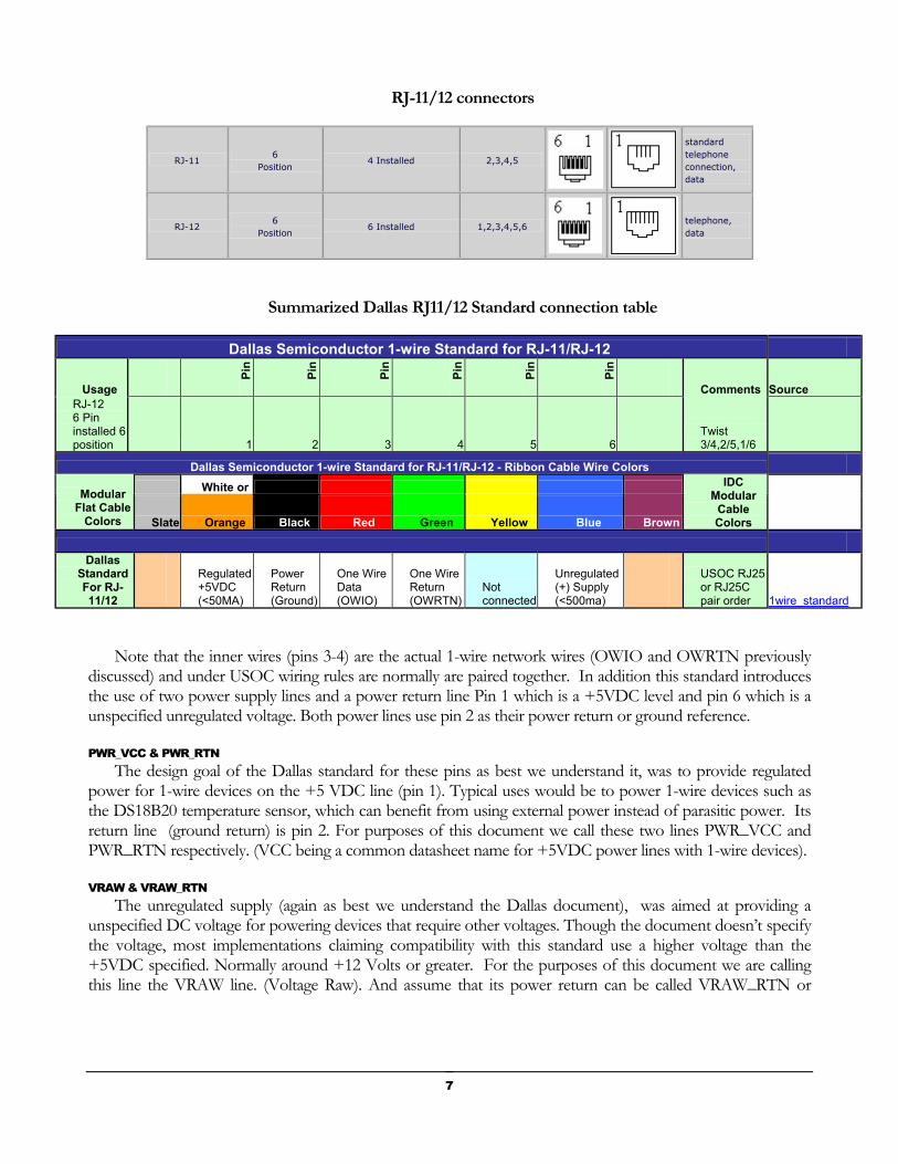
RJ-11/12 connectors
RJ-11 6
Position 4 Installed 2,3,4,5
standard telephone connection, data
RJ-12 6
Position 6 Installed 1,2,3,4,5,6
telephone, data
Summarized Dallas RJ11/12 Standard connection table
Dallas Semiconductor 1-wire Standard for RJ-11/RJ-12
Usage
Pin
Pin
Pin
Pin
Pin
Pin
Comments Source RJ-12 6 Pin installed 6 position 1 2 3 4 5 6
Twist 3/4,2/5,1/6
Dallas Semiconductor 1-wire Standard for RJ-11/RJ-12 - Ribbon Cable Wire Colors
White or Modular Flat Cable
Colors Slate Orange Black Red Green Yellow Blue Brown
IDC Modular
Cable Colors
Dallas Standard For RJ-11/12
Regulated +5VDC (<50MA)
Power Return (Ground)
One Wire Data (OWIO)
One Wire Return (OWRTN)
Not connected
Unregulated (+) Supply (<500ma)
USOC RJ25 or RJ25C pair order 1wire_standard
Note that the inner wires (pins 3-4) are the actual 1-wire network wires (OWIO and OWRTN previously discussed) and under USOC wiring rules are normally are paired together. In addition this standard introduces the use of two power supply lines and a power return line Pin 1 which is a +5VDC level and pin 6 which is a unspecified unregulated voltage. Both power lines use pin 2 as their power return or ground reference.
PWR_VCC & PWR_RTN The design goal of the Dallas standard for these pins as best we understand it, was to provide regulated
power for 1-wire devices on the +5 VDC line (pin 1). Typical uses would be to power 1-wire devices such as the DS18B20 temperature sensor, which can benefit from using external power instead of parasitic power. Its return line (ground return) is pin 2. For purposes of this document we call these two lines PWR_VCC and PWR_RTN respectively. (VCC being a common datasheet name for +5VDC power lines with 1-wire devices).
VRAW & VRAW_RTN The unregulated supply (again as best we understand the Dallas document), was aimed at providing a
unspecified DC voltage for powering devices that require other voltages. Though the document doesn’t specify the voltage, most implementations claiming compatibility with this standard use a higher voltage than the +5VDC specified. Normally around +12 Volts or greater. For the purposes of this document we are calling this line the VRAW line. (Voltage Raw). And assume that its power return can be called VRAW_RTN or
7
Voltage Raw Return. In the Dallas standard this line would be Pin 2 the same line used as our +5 VDC (VCC_RTN) line. So VRAW_RTN and PWR_RTN in the Dallas standard are one and the same.
Problems with the Dallas Standard As you can imagine, being an unspecified voltage level (the VRAW line) can present many incompatibilities
in systems since this voltage could be anything (say 0-48 volts or more). And begins to show the need for a tighter specification document. Note also that Pin 5 is specified as being unconnected in the Dallas standard. So any devices that connect this pin are not really Dallas standard compatible. A condition that was not that infrequent in our review of 1-wire boards.
In addition the Dallas standard was not designed to use twisted pair cable (CAT) cabling, but rather flat modular cabling (telephone style) and uses the widely considered obsolete USOC standard. Flat modular cabling is not manufactured to the higher standards of CAT cabling any its wire color codes can vary according to manufactures. (In our review of many flat cable manufactures we typically found pin 1 to vary between white and orange and the remaining colors remaining the same. Consult the table for common pin color assignments).
8
RJ45 and CAT cabling However the Dallas standard even with its problems was as very welcome addition to the 1-wire knowledge base as it begins to introduce the idea of standards in the 1-wire network world. And we wish to thank Dallas Semiconductor for providing this great starting point. It provides enough information for many manufactures to start to build compatible 1-wire systems. However it still doesn’t address the issues of using common CAT cabling and the widely available RJ-45 connectors.
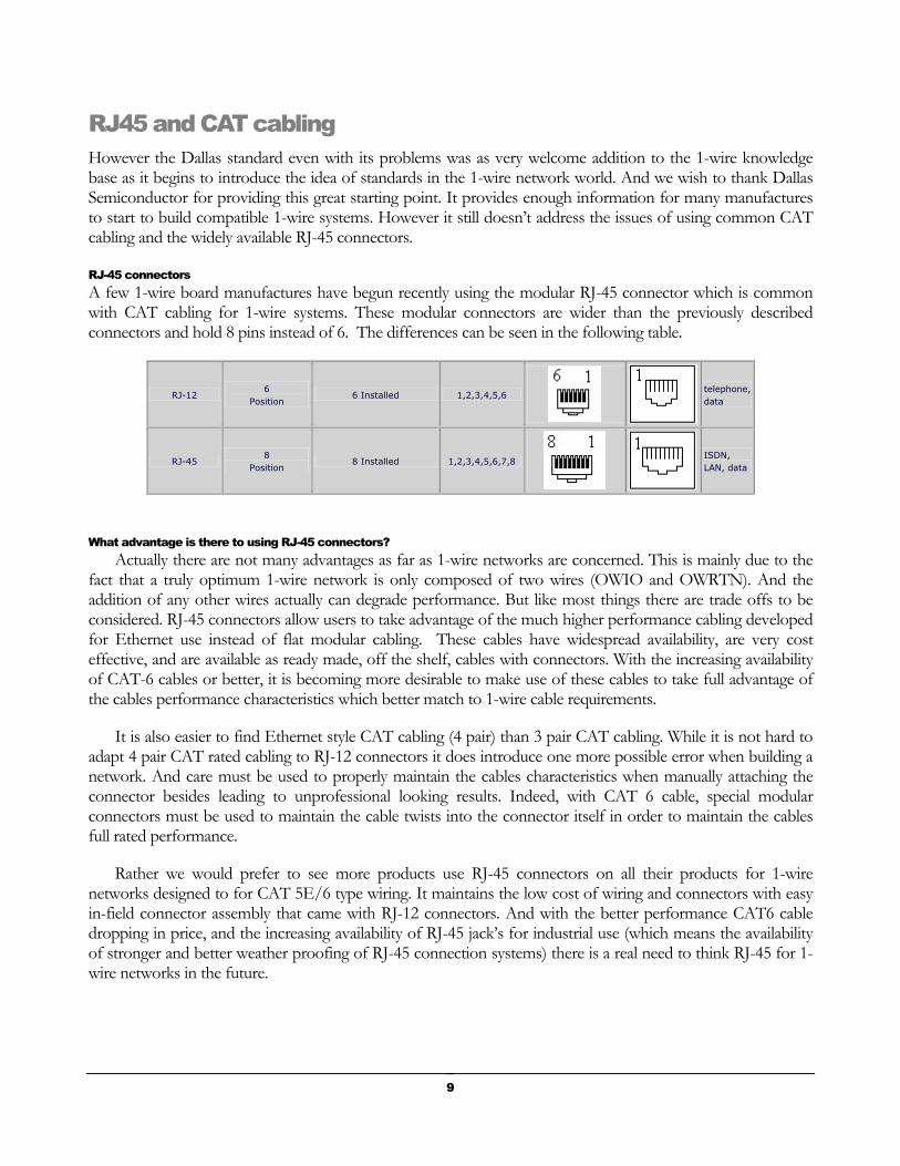
RJ-45 connectors A few 1-wire board manufactures have begun recently using the modular RJ-45 connector which is common with CAT cabling for 1-wire systems. These modular connectors are wider than the previously described connectors and hold 8 pins instead of 6. The differences can be seen in the following table.
RJ-12 6
Position 6 Installed 1,2,3,4,5,6
telephone, data
RJ-45 8
Position 8 Installed 1,2,3,4,5,6,7,8
ISDN, LAN, data
What advantage is there to using RJ-45 connectors? Actually there are not many advantages as far as 1-wire networks are concerned. This is mainly due to the
fact that a truly optimum 1-wire network is only composed of two wires (OWIO and OWRTN). And the addition of any other wires actually can degrade performance. But like most things there are trade offs to be considered. RJ-45 connectors allow users to take advantage of the much higher performance cabling developed for Ethernet use instead of flat modular cabling. These cables have widespread availability, are very cost effective, and are available as ready made, off the shelf, cables with connectors. With the increasing availability of CAT-6 cables or better, it is becoming more desirable to make use of these cables to take full advantage of the cables performance characteristics which better match to 1-wire cable requirements.
It is also easier to find Ethernet style CAT cabling (4 pair) than 3 pair CAT cabling. While it is not hard to adapt 4 pair CAT rated cabling to RJ-12 connectors it does introduce one more possible error when building a network. And care must be used to properly maintain the cables characteristics when manually attaching the connector besides leading to unprofessional looking results. Indeed, with CAT 6 cable, special modular connectors must be used to maintain the cable twists into the connector itself in order to maintain the cables full rated performance.
Rather we would prefer to see more products use RJ-45 connectors on all their products for 1-wire networks designed to for CAT 5E/6 type wiring. It maintains the low cost of wiring and connectors with easy in-field connector assembly that came with RJ-12 connectors. And with the better performance CAT6 cable dropping in price, and the increasing availability of RJ-45 jack’s for industrial use (which means the availability of stronger and better weather proofing of RJ-45 connection systems) there is a real need to think RJ-45 for 1-wire networks in the future.
9
On using RJ11/12 plugs in a RJ45 jack While with some care, RJ-11/RJ-12 terminated cables will plug into a RJ-45 jacks. This is not
recommend! RJ-45 jacks were not designed to be used in this manner. (To the best of our information using an RJ45 and plugging smaller modular connectors such as RJ11 into it is not recommended because the plastic housing on the RJ11 lips deforms the RJ45 #1 and #8 contacts inside the jack.) So though it may work for a while you may be destroying the ability of the RJ-45 jack to function properly in the future and severely damaging its life cycle.
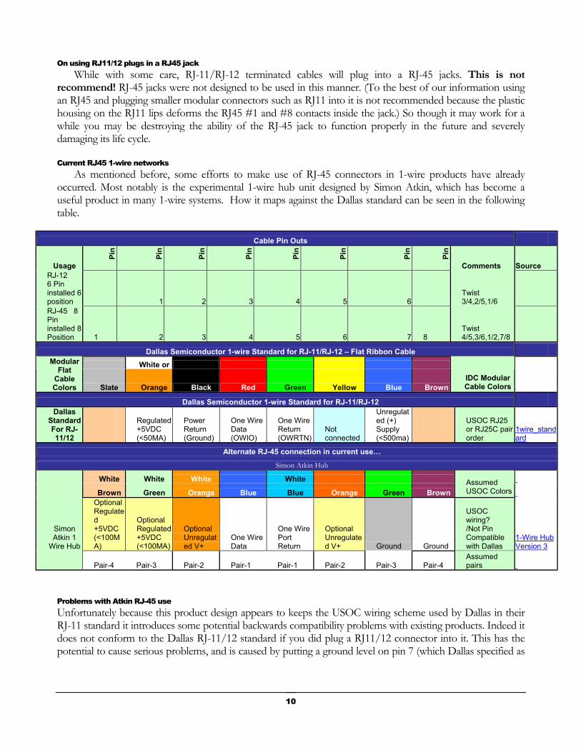
Current RJ45 1-wire networks As mentioned before, some efforts to make use of RJ-45 connectors in 1-wire products have already
occurred. Most notably is the experimental 1-wire hub unit designed by Simon Atkin, which has become a useful product in many 1-wire systems. How it maps against the Dallas standard can be seen in the following table.
Cable Pin Outs
Usage
Pin
Pin
Pin
Pin
Pin
Pin
Pin
Pin
Comments Source RJ-12 6 Pin installed 6 position 1 2 3 4 5 6
Twist 3/4,2/5,1/6
RJ-45 8 Pin installed 8 Position 1 2 3 4 5 6 7 8
Twist 4/5,3/6,1/2,7/8
Dallas Semiconductor 1-wire Standard for RJ-11/RJ-12 – Flat Ribbon Cable
White or Modular Flat
Cable Colors Slate Orange Black Red Green Yellow Blue Brown
IDC Modular Cable Colors
Dallas Semiconductor 1-wire Standard for RJ-11/RJ-12
Dallas Standard For RJ-11/12
Regulated +5VDC (<50MA)
Power Return (Ground)
One Wire Data (OWIO)
One Wire Return (OWRTN)
Not connected
Unregulated (+) Supply (<500ma)
USOC RJ25 or RJ25C pair order
1wire_standard
Alternate RJ-45 connection in current use… Simon Atkin Hub
White White White White
Brown Green Orange Blue Blue Orange Green Brown Assumed USOC Colors
Simon Atkin 1
Wire Hub
Optional Regulated +5VDC (<100MA)
Optional Regulated +5VDC (<100MA)
Optional Unregulated V+
One Wire Data
One Wire Port Return
Optional Unregulated V+ Ground Ground
USOC wiring? /Not Pin Compatible with Dallas
1-Wire Hub Version 3
Pair-4 Pair-3 Pair-2 Pair-1 Pair-1 Pair-2 Pair-3 Pair-4 Assumed pairs
Problems with Atkin RJ-45 use Unfortunately because this product design appears to keeps the USOC wiring scheme used by Dallas in their RJ-11 standard it introduces some potential backwards compatibility problems with existing products. Indeed it does not conform to the Dallas RJ-11/12 standard if you did plug a RJ11/12 connector into it. This has the potential to cause serious problems, and is caused by putting a ground level on pin 7 (which Dallas specified as
10
being a Unregulated (+) Supply (<500ma)). Or optionally allowing users to put the Unregulated V+ power on pin 3 which Dallas specified as a Power Return (Ground). Its left to the installer to be sure they don’t cause problems in their wiring with other 1-Wire products. This solution while suitable for experimenters and knowledgeable hobbyist (for which the product was intended) does not address the needs of the wider potential manufacturing market.
A Note on the USOC standard In general avoid using USOC anywhere in the cable plant for Ethernet or data communications. Though it
is fine for up to 6 wire 1-wire networks. USOC wiring was the pre-data standard for telecommunications. When a Ethernet LAN NIC transmits on two wires, it expects them to be a pair of wires that are twisted together. Ethernet transmits on pins 1 and 2. Notice that on a USOC cable, they aren't twisted together. This greatly increases the crosstalk on the line and causes transmission to be more unreliable.
11
Chapter
3 33A New Standard
Building on what went before…
1WRJ45 Proposed Standard Instead we offer a slightly different approach where we suggest a standard based around the more modern
T568A Telecommunications Industry Association wiring standard widely used in the Ethernet industry. This gives us a widespread industry standard cabling/coloring scheme and when combined with the Dallas Semiconductor 1-wire standard for RJ11/12 gives backward pin compatibility. (The T568B standard would work as well but we would like to choose just one to fix the wire color scheme used to only one standard. Although the use of a T568B wired cable would not effect its operation in any way.)
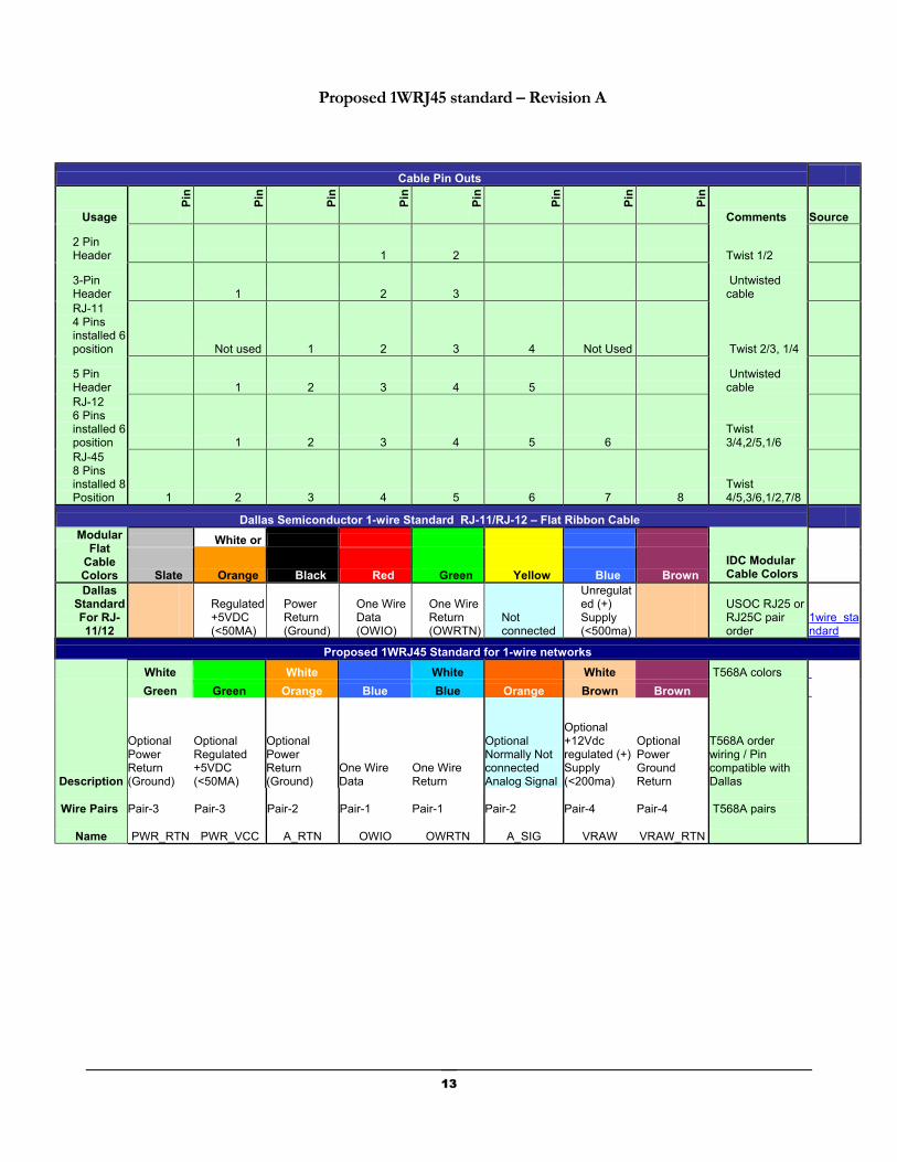
This is best understood by reviewing the proposed standard on the following page. It is basically the Dallas specification with the addition of ground return pins on the outer pins applied to the T568A wiring scheme. This allows the extra pins of the RJ-45 to remain as twisted pairs under the T568A spec. By using the T568A specification we gain the use of a standardized international wire color-coding and wire pairing with adapted1-wire pin use for our cabling needs.
It also has the advantage of being able to be also useful in also describing connectors with fewer pins than in the RJ-45 connector. We have added several other connector styles to the top of the table that show how this standard might work with connectors with as few as two pins. In addition we have taken this opportunity to actually name each pin and identify its twisted wiring pair number when used in a RJ-45 configuration. This is to allows connectors and boards traces to be identified by their use by manufactures of 1-wire devices Also note that we have made several of the lines optional and will talk more about this and the actual meaning of the other changes later in this document.
We feel that the use of this proposed standard would make it much easier for end users and installers of a 1-wire network in understanding and properly installing 1-wire networks while maintaining great flexibility in designing any particular network.
12
Proposed 1WRJ45 standard – Revision A
Cable Pin Outs
Usage
Pin
Pin
Pin
Pin
Pin
Pin
Pin
Pin
Comments Source
2 Pin Header 1 2 Twist 1/2
3-Pin Header 1 2 3
Untwisted cable
RJ-11 4 Pins installed 6 position Not used 1 2 3 4 Not Used Twist 2/3, 1/4
5 Pin Header 1 2 3 4 5
Untwisted cable
RJ-12 6 Pins installed 6 position 1 2 3 4 5 6
Twist 3/4,2/5,1/6
RJ-45 8 Pins installed 8 Position 1 2 3 4 5 6 7 8
Twist 4/5,3/6,1/2,7/8
Dallas Semiconductor 1-wire Standard RJ-11/RJ-12 – Flat Ribbon Cable
White or Modular Flat
Cable Colors Slate Orange Black Red Green Yellow Blue Brown
IDC Modular Cable Colors
Dallas Standard For RJ-11/12
Regulated +5VDC (<50MA)
Power Return (Ground)
One Wire Data (OWIO)
One Wire Return (OWRTN)
Not connected
Unregulated (+) Supply (<500ma)
USOC RJ25 or RJ25C pair order
1wire_standard
Proposed 1WRJ45 Standard for 1-wire networks White White White White T568A colors Green Green Orange Blue Blue Orange Brown Brown
Description
Optional Power Return (Ground)
Optional Regulated +5VDC (<50MA)
Optional Power Return (Ground)
One Wire Data
One Wire Return
Optional Normally Not connected Analog Signal
Optional +12Vdc regulated (+) Supply (<200ma)
Optional Power Ground Return
T568A order wiring / Pin compatible with Dallas
Wire Pairs Pair-3 Pair-3 Pair-2 Pair-1 Pair-1 Pair-2 Pair-4 Pair-4 T568A pairs
Name PWR_RTN PWR_VCC A_RTN OWIO OWRTN A_SIG VRAW VRAW_RTN
13
Defining the Optional Connections Because every time we put a signal in the cable near the 1-wire network wires we add potential noise and
probability increase its capacitance the power lines should be declared only optional lines and by default are NOT connected. All connections of the +12 Volt and +5 Volt lines to the RJ-45 connector to be made by some sort of jumper or header normally NOT connected. This is mandatory for compliance to this specification for new board designs using RJ-45 connectors. This gives us a standard which is totally Dallas 1-wire compliant to begin with. And any power use is made by deliberate actions of the 1-wire network installer to connect power through the cable. Thus the default wiring would NOT have power through the cable (maximizing the 1-wire network performance in CAT cables).
Alternate power jacks It is also highly recommended that secondary alternate provisions should also be made on all boards using a
RJ-45 connector for connecting to +12 volts and or +5 volts as appropriate and logical by the board design. Thus allowing for the use of a separate power cable when possible. A typical suggested implementation would be the use of pin headers or a 2.1mm (center positive) power jack. Boards or jacks should be clearly marked for their power requirements.
Color coding By mandatory compliance to the T568B wire color scheme (even though the T568B would also work)
functional color coding of each lines function is achieved and confusion about what each wire does is relieved.. Older already installed systems should be updated to this scheme as maintaince schedules and time permits. And only when fully compliant with this wire color-coding would an entire 1-wire network be deemed 1WRJ45 compliant.
Labeling of power requirements Boards and devices using the 1WRJ45 should be clearly labeled as to their expected power and current
requirements (Worst and Typical case) and or their abilities to supply power for other devices.
14

Review of the proposed specification Adopts the T568A specification for actual RJ-45 wiring pairs
Adopts the T568A specification for standard wire color-coding for CAT type cabling when using RJ-45 connectors on a 1-wire network.
Uses the existing RJ-11/12 Dallas Semiconductor Specifications for 1-wire networks mapped to RJ-45 pin connection for physical pin use. Thus allowing for pseudo backwards compatibility to RJ-11/12 modular connectors.
Adopts standardized naming of pin connections for 1-wire on a RJ-45 connector.
Defines all connections other the basic OWIO and OWRTN signals as optional
Defines all optional signals settable through the use of jumpers for RJ-45 connectors
Power through the cable is now an optional (installer/user option) on all devices using RJ-45 connectors
Tightens specifications of power to limit voltages to +5VDC at 50ma and +12 VDC at 200ma.
Sets a suggested max cable length for using power through the cable using the +12VDC power at 250 feet.
Sets a suggested max cable length for using power through the cable using the +5VDC power at 50 feet at 1000 feet.
Gives suggested pin standards for other sized connectors (from 2 to 8 pins) where possible.
Adds an optional short distance DC analog sense monitoring line (limited to 0-5 VDC @ <10kHz)
15

16
Chapter
4 44Details
Its all in the fine print…
Understanding the reasoning… About the power supply lines
We feel that a bit of discussion about the uses and reasoning behind the changes in the use of power supply lines is also in order. As mentioned previously, the use of the regulated +5Vdc supply as specified in the original Dallas standard as best as we understand it was to allow for local direct powering of sensors and chips. In this way you could power say a series of DS18B20 temperature sensors on a single line or other similar uses. It was never designed to power boards over any distance or even to supply that much current, hence the limit of <50ma in the Dallas spec. This is just a way of insuring regulated power to a few local devices or chips, and you can power quite a lot DS18B20’s at 50ma over 1000 feet of cable. Just watch out for the voltage drop due to cable resistance in long cables.
But for the needs of an actual power delivery system for a board (assuming it had to be done through a single cable) was to be left up to the unregulated supply line (pin 7 on a RJ-45 connector). This power line was specified as unregulated and capable of delivery up to 500ma.
However in our view this causes several problems to a board designer. The biggest one is in order to use the Dallas specification you would have to deal with an unknown voltage. And you don’t even know if it is DC voltage or not! To our view this is totally unacceptable. It appear that most board designers are using the logical assumption that this would be a 12 volts unregulated supply line but there is NOTHING to guarantee this which could cause severe problems with some boards.
When you try to run power through a cable you have to deal with potential power losses generated by the length of the cable among many other issues. Then add that to that the requirements of any regulation devices or DC to DC converters on the ends of the cable to insure that you have enough voltage/current to supply your board or device.
17

An example design problem As an example of how this affects a system designer lets walk through this as an exercise.
Assumptions and requirements We will use the following assumptions for an initial starting point.
1. That our CAT5/6 cable being used has a resistance of 30 ohms per 1000 feet (Actually most is closer to 28, but we will use a worst case number here).
2. And that we are going to power a board at the end of 500 feet of cable.
3. And our required supply voltage is for a board that expects 12 volt @ 500 ma. at its input. Which will be used to regulate down to a 5 volts supply voltage. (many 1-wire boards do exactly this, though not at this current requirement). All this would be a legal spec under the current Dallas RJ-11/RJ-12 standard.
Calculating cable voltage loss So lets start by calculating how much voltage will be loss over the cable length using the formula…
(CableLength * Cable resistance per 1000 * AmpDraw) / 1000 = Vdrop
Where AmpDraw or current requirement is the number of amps drawn by the equipment at the given input voltage level. So using our numbers, we get:
(500 * 30 * . 5) / 1000 = 7.5 Vdrop
For a total voltage drop of 7.5 volts over the length of the cable!
So if we wish to maintain the required 12 volts at 500ma that we wanted through the cable to the board, we will have to input 19.5 volts into the cable.
Vdrop + Voltage = InputVoltage
Or 7.5+12 = 19.5 volts
Calculating Power requirements Power is expressed as Watts and Voltage * Amps = Watts, and thus Amps = Watts / Volts
So our board requires (12 * .5) = 6 Watts total at its input and the cable will lose (7.5 volts * .5) = 3.75 Watts so we will need a total of (6 + 3.75) = 9.75 Watts of power going into the cable.
Now if our board is connected to the power source using only inches of cable, instead of the 500 feet in the previous example, it would not be seeing that 12 volts at its input that it required. But rather nearly the full 19.5 volts instead. So depending on the board’s design to handle over voltages, we maybe will see that magic smoke released when the 5 volts regulator went poof because it exceeded its maximum input voltage range.
. Anyway, you get the idea, we deliberately picked some numbers that would start out looking reasonable, but would turn out creating a problem on some devices to illustrate the need for some tighter specifications.
18
Indeed there is nothing in the Dallas specification that says that the unregulated voltage isn’t 48 volts @ 500 ma. or more. Which would almost certainly cause problems for all the existing 1-wire boards we know about.
Towards A better answer What we want to do is supply a reasonable amount of current, at a reasonable voltage, over a reasonable
length of cable, in order to drive the circuitry of boards and its components. If we are going to need to supply large amounts of current, we would be far better off using either a separate power cable or a local power supply and NOT try to power through the same cable we are sending the 1-wire signals on. But is all we want to do is power some logic or sensors or maybe power some DC to DC isolation converters for ground isolation using only 1 cable then we need to make some assumptions.
1WRJ45 Current requirements So the first thing we need to address is just how much current we really need. Of course this depends on
your network configuration. We don’t believe that we should attempt to handle the case of 50 boards and 500 sensors all powered on one 1000 foot length of cable. Networks like this are better off with separate power cables. And they should most likely be using 1-wire hubs to break the network apart anyway. But if we use as our model a system based on the idea of 1-wire hubs, each with a short network cable leg (say max of 250 feet per leg for powered boards). And only requiring it to be able to power 2-8 boards per leg (at 20-25 ma average current draw per board at the end of that cable), then 200ma seems about right. So this gives us a:
Vdrop = (CableLength * 30 * AmpDraw) / 1000
Or
(300 * 30 * .2) / 1000 = 1.5 Vdrop.
This maximum 1.5 voltage drop through the cable gives us a more reasonable range of voltages to handle
1WRJ45 Voltage requirements We now need to decide how much voltage we need. We could use the 48 or 24 volts that is used in some
Power over Ethernet scheme, such as used in the IEEE 802.3 standards). But this exceeds the voltage capabilities of most existing 1-wire boards to handle Plus you would need expensive additional power circuitry on the board. And it does not really matching up well to the existing Dallas standards wiring standards. So we are going to have to select the voltage ourselves.
If we were to use a well regulated 12 volts DC level, then most of the current +5 volt regulators could handle this as an input without any additional circuitry. Allowing for direct conversion from 12 volts to the commonly used 5 volts. And at the maximum cable length, which produces the worst case maximum allowed voltage drop in the cable, would still put an allowable voltage of 10.2 volts on the input line.
Voltage – Vdrop = Available volts
Or the minimum allowed voltage would be
(12 – 1.5) = 10.5 volts available at the far end of our cable
This is high enough that we can still power things like a DS2438 at 10 volts (maybe for a barometer circuit like the one used in the JJWare barometer board) if we wanted to using a good LDO regulator and avoid the need for a boast regulator. So most existing 1-wire boards would still work at this distance. Its important to
19

remember this supply is for the occasional 1-wire logic boards. We are not trying to provide power for heaters, relays or servos or other high current devices. Any of these uses should be using a separate cable (shielded) or power supply source anyway to help keep the noise away from the 1-wire circuits
1WRJ45 Power requirements Given our formula of:
(Volts * Amps) = Watts
For 12 volts at 200ma the power is:
12*.2 = 2.4 Watts will be made available to the boards.
And with the maximum cable Vdrop of 1.5 volts the power loss in the cable is:
(1.5 *.2) = .3 Watts lost over the length of the cable
So the supply would have to source
2.7 Watts, (2.4 + .7) = 2.7 Watts
Which is considerably more reasonable than the 9.75 watts required in our first example.
20
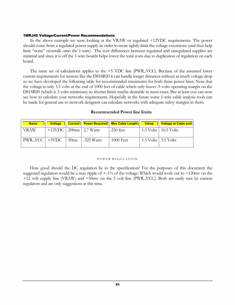
1WRJ45 Voltage/Current/Power Recommendations In the above example we were looking at the VRAW or regulated +12VDC requirements. The power
should come from a regulated power supply in order to more tightly limit the voltage excursions (and thus help limit “noise” crosstalk onto the 1-wire). The cost differences between regulated and unregulated supplies are minimal and since it is off the 1-wire boards helps lower the total costs due to duplication of regulation on each board.
The same set of calculations applies to the +5 VDC line (PWR_VCC). Because of the assumed lower current requirements for sensors like the DS18B20 it can handle longer distances without as much voltage drop so we have developed the following table for recommended maximums for both these power lines. Note that the voltage is only 3.5 volts at the end of 1000 feet of cable which only leaves .5 volts operating margin on the DS18B20 (which is 3 volts minimum) so shorter limits maybe desirable in most cases. But at least you can now see how to calculate your networks requirements. Hopefully in the future some 1-wire cable analysis tools can be made for general use so network designers can calculate networks with adequate safety margins in them.
Recommended Power line limits
Name Voltage Current Power Required Max Cable Length Vdrop Voltage at Cable end
VRAW +12VDC 200ma 2.7 Watts 250 feet 1.5 Volts 10.5 Volts
PWR_VCC +5VDC 50ma .325 Watts 1000 Feet 1.5 Volts 3.5 Volts
P O W E R R E G U L A T I O N
How good should the DC regulation be in the specification? For the purposes of this document the suggested regulation would be a max ripple of +-1% of the voltage. Which would work out to <120mv on the +12 volt supply line (VRAW) and <50mv on the 5 volt line (PWR_VCC). Both are easily met by current regulators and are only suggestions at this time.
21
The Aux or Analog signal lines In addition to the normal 1-wire signal lines two additional lines are specified that can be configured to act as auxiliary power or analog signal lines. They are normally NOT connected (in order to minimize capacitive loading of the 1-wire signal lines) and are normally used and terminated only over short segments of cable (a few feet) which helps limit their impact on other signals.
A_GND The A_RTN pin in the 1WRJ45 specification serves two purposes. It can act as a power ground return if
needed for backwards compatibility when using fewer than 8 pin configurations of the 1WRJ45 spec. Or it can act as the Ground return line for the A_SIG line. In ether case it is always a ground return line. It is unconnected by default.
A_SIG This line is normally not used in 1-wire systems and is to be left unconnected by default. It is sometimes
very convient to be able to monitor a slowly changing voltage level from some non 1-wire device through the same cable carrying 1-wire information. This line is designated to that purpose. The voltage must be between 0-+5VDc and must be a very slow changing line (to minimize 1-wire data interface and allow time for error recovery). A suggested maximum change rate would be in the order of <10 kHz. And more preferably a steady DC level. This signal is rarely passed from 1-wire device to another and normally terminates at the 1st 1-wire unit encountered in the network. Generally a low pass filter is also connected to this line when used as analog voltage monitor. Manufactures should perform testing using a minimum of 250 feet of CAT5E cable when checking for interference from this signal line on the OWIO line when designing boards.
On the use of Non-Keyed RJ-45 jacks How do we prevent accidental interconnection to Ethernet RJ-45 networks or some other system using RJ-
45 jacks? The obvious answer is to use keyed jacks. However using keyed jacks and plugs defeat the main reason for using RJ-45 connectors in the first place, its widespread availability and cost effectiveness. Keyed jacks would only work if everyone used them, which is unlikely given the widespread availability of non-keyed cables and the extra costs associated with them. The only real answer, and its not a good one, is to suggest that individual company wiring standards be rigorously followed and that a particular cable sheath color is set aside for 1-wire cables. But this offers no prevention from accidental connection to Ethernet cables and would have to be handled by plant installation standards. So the use of keyed jacks will have to be left to the development a future standard, maybe as an industrialized version of this standard.
22
A general model for a complex 1-wire system design Our reference design for a reasonable, complex 1-wire 1WRJ45 compatible system network would be
based around the idea of 1-wire hubs. Each capable of switch able supplying power for several network legs, each leg with a couple of devices/boards and or sensors. This achieves two goals, it keeps the maximum individual cable distances to a minimum by separately powering each leg. And since we have fewer boards potentially on each leg it lowers the total needed drive current per section. With current requirements of 20-50ma for a board and the cable distance of about 250 feet max being supplied with power through the cable, we could handle say 4-8 powered boards at 25-50ma each.
The advantages of such a network would be easy connection of devices and sensors. Besides being easier to design for and switch, it should produce less ‘noise” or cross talk onto the 1-wire network signals Plus being able to supply say 8 hub legs at 12 volts 200ma each (8 * 200ma = 1600ma from a central supply is still not a large power supply problem, where as 48 volts at 500 ma or 4 Amps is going to be more costly on a per board basis). It also makes power switching easier to implement. So all legs do not have to be powered on at any given time so redudent legs could be designed into a system and only switched on when needed.
Since sensors can be local powered from the nearest board we also do not add much to the total nearby capacitance load on the data signals. Yet we are still able to achieve maximum performance from the sensors. The flexible optional structure of the 1WRJ45 specification allows networks to be custom designed for a particular need but still be based around the idea of common connectors. While it does increase the responsibility of the network designer it also gives them great flexibility in minimizing cable line effects.
23
Chapter
5 55Some Suggestions Record Keeping
One of the easiest ways to help keep up a 1-wire network is to use good record keeping practices. We find it much easier if we maintain installation logs about all our equipment. Good record keeping of physical location of all hardware is a must. This helps identify areas or equipment that require maintaince.
For example, by keeping installation information all the way down to individual cables we are able identify when it might be a good time to perform checks for UV damage on sections of our outside cabling and use planned life cycle replacements as needed.
With the increased flexibility of the 1WRJ45 good records of the network installation become even more important when locating problem areas in a network.
Wire color coding CAT Cabling (White sheath color for Outdoor, Orange for Indoor use is suggested)
It also helps to identify each physical item in the network. Things like color paint dots can be useful to prevent installer connection errors. Colored heat shrink or labels can help identify special cabling. Use of color-coded boots on RJ45 plugs is also useful.
CAT5E & CAT6 cable comes in many different colors (sheaths). The most important thing is to select a consistent color for your 1-wire network. Preferably one not uses for telephone or other communications (Ethernet) wiring and stick to it for all your in-house/plant wiring. This makes it easier to avoid improper connections with other systems using modular connectors.
In our own plant we have standardized on White cables for our outdoor rated installations and Orange for our indoor uses (though yellow or orange might be preferred for outdoor use and white for indoor if we were doing it over).. These colored cables are NOT used in any of our Ethernet cabling or patch wiring. Buried CAT rated cable is also used when appropriate.
The actual wire colors and their pin associations are done based on the TIA-568A color standards previously described in the 1WRJ45 section. This allows us to know the proper pin connections for any 1-wire cable.
IDC Flat Modular cable (Black cable sheath color suggested)
24
Flat modular cabling is normally only used for very short sensor inner-connects or very short board to board interconnects (<6”). It does not have the performance of good quality CAT5E or CAT6 cable and is not therefore suggested for most uses.
When we do use it we follow the standard color coding as used by several manufactures (see 1WRJ45 table for details) so as to be able to also use ready made cable assemblies. These are available from several sources (Digi-key, and others). Be sure to specify the “REVERSED” style connection system when ordering so as to maintain the flat connections required in the 1-wire system. (One connector is up and the other down). We also prefer that the outer sheath color to be black for 1-wire installations (White or Silver Satin is used for our telephone system).
RJ-45 insertion cycles Installers should remember that modular connectors are design for a limited number of insertions cycles.
This number is much smaller than most people think (on the order of 200 hundred insertion cycles from some manufactures). So plan ahead and limit your insertion cycles for best performance from the connectors.
Conclusion Though the 1WRJ45 standard was originally designed to full-fill our own companies needs for a 1-wire
standard we hope others will find it useful also. With the hope that other manufactures can begin to standardize around this standard for there products and thus make it easier for developers, designers and end users to take advantage of the features that 1-wire networks offer.
Other reference documents of interest A Guide to connectors
A Quick Guide to 1WRJ45
A Quick Guide to Network Connections
25

Chapter
6 66Index
A E K R Index 1, 1 Index 1, 1 Index 1, 1 Index 1, 1
L Index 1, 1 Index 1, 1 Index 1, 1
S Index 1, 1 Index 1, 1 Index 1, 1 Index 2, 2 Index 2, 2
Index 3, 3 Index 1, 1 Index 2, 2 Index 1, 1 Index 1, 1 Index 1, 1 Index 1, 1 Index 1, 1 Index 1, 1 Index 1, 1 Index 1, 1 Index 1, 1
B G Index 2, 2 Index 2, 2 Index 1, 1 Index 1, 1
Index 1, 1 Index 1, 1 Index 1, 1 Index 1, 1 Index 1, 1 Index 1, 1 Index 1, 1 Index 1, 1
T Index 1, 1 Index 1, 1 Index 1, 1 Index 2, 2 Index 1, 1 Index 1, 1
C M Index 1, 1 Index 1, 1 Index 1, 1 Index 1, 1
H Index 1, 1 Index 1, 1 Index 1, 1 Index 1, 1 Index 1, 1 Index 1, 1
Index 1, 1 Index 1, 1 Index 1, 1 Index 2, 2
W Index 1, 1 Index 2, 2 Index 2, 2
N Index 1, 1 Index 1, 1 Index 1, 1 Index 1, 1 Index 1, 1
Index 1, 1 Index 1, 1 Index 2, 2 Index 1, 1
D Index 1, 1 Index 1, 1 Index 1, 1 Index 1, 1 Index 2, 2 Index 1, 1
Index 1, 1 Index 2, 2 Index 1, 1 Index 1, 1 Index 1, 1 Index 1, 1 Index 1, 1 Index 1, 1 Index 1, 1 Index 1, 1 Index 1, 1 Index 1, 1 Index 1, 1 Index 1, 1 Index 1, 1 Index 1, 1
26

27