Standard TNC Parameter Settings for Santa Clara … TNC Parameter Settings for Santa Clara County...
34
Standard TNC Parameter Settings Rev: 07‐Apr‐2016 Santa Clara County ARES®/RACES Page 1 of 34 Standard TNC Parameter Settings for Santa Clara County Packet Network Updated for SCCo Packet Installer v102 Table of Contents Introduction .................................................................................................................................................. 3 Fictitious Call Signs ........................................................................................................................................ 3 Standard TNC Settings for Outpost Users ..................................................................................................... 4 Preconfigured TNCs in Outpost................................................................................................................. 4 Creating an Outpost TNC Command List .................................................................................................. 4 Standard TNC Settings for Manual BBS Sessions ........................................................................................ 13 Manual Operations Workflow ................................................................................................................ 13 TNC Commands for Manual Operations ................................................................................................. 15 Explanation of TNC Parameters .................................................................................................................. 19 Restore Factory Defaults......................................................................................................................... 19 Full Command Set ................................................................................................................................... 19 Mode Control .......................................................................................................................................... 19 Character Length ..................................................................................................................................... 20 Station Identification .............................................................................................................................. 21 Channel Access........................................................................................................................................ 23 Transport and Session Control ................................................................................................................ 25 Radio Timing ........................................................................................................................................... 26 Flow Control ............................................................................................................................................ 27 Packetization Control .............................................................................................................................. 27 Stream Control ........................................................................................................................................ 29 GPS Control ............................................................................................................................................. 30 Other TNCs .................................................................................................................................................. 32 AEA PK‐232MBX ...................................................................................................................................... 32
Transcript of Standard TNC Parameter Settings for Santa Clara … TNC Parameter Settings for Santa Clara County...

Standard TNC Parameter Settings Rev: 07‐Apr‐2016
Santa Clara County ARES®/RACES Page 1 of 34
StandardTNCParameterSettingsforSantaClaraCountyPacketNetworkUpdatedforSCCoPacket Installerv102
TableofContentsIntroduction .................................................................................................................................................. 3
Fictitious Call Signs ........................................................................................................................................ 3
Standard TNC Settings for Outpost Users ..................................................................................................... 4
Preconfigured TNCs in Outpost................................................................................................................. 4
Creating an Outpost TNC Command List .................................................................................................. 4
Standard TNC Settings for Manual BBS Sessions ........................................................................................ 13
Manual Operations Workflow ................................................................................................................ 13
TNC Commands for Manual Operations ................................................................................................. 15
Explanation of TNC Parameters .................................................................................................................. 19
Restore Factory Defaults ......................................................................................................................... 19
Full Command Set ................................................................................................................................... 19
Mode Control .......................................................................................................................................... 19
Character Length ..................................................................................................................................... 20
Station Identification .............................................................................................................................. 21
Channel Access ........................................................................................................................................ 23
Transport and Session Control ................................................................................................................ 25
Radio Timing ........................................................................................................................................... 26
Flow Control ............................................................................................................................................ 27
Packetization Control .............................................................................................................................. 27
Stream Control ........................................................................................................................................ 29
GPS Control ............................................................................................................................................. 30
Other TNCs .................................................................................................................................................. 32
AEA PK‐232MBX ...................................................................................................................................... 32
Standard TNC Parameter Settings Rev: 07‐Apr‐2016
Santa Clara County ARES®/RACES Page 2 of 34
AEA PK‐88 ................................................................................................................................................ 32
Alinco DR‐620T/DR‐635T Radio with Internal EJ‐50U TNC ..................................................................... 32
Kantronics 9612 ...................................................................................................................................... 32
Kenwood TM‐D700 Radio with Internal TNC .......................................................................................... 32
Kenwood TS‐2000 Radio with Internal TNC ............................................................................................ 32
MFJ 1270B/1274B ................................................................................................................................... 32
Revision History .......................................................................................................................................... 34
Standard TNC Parameter Settings Rev: 07‐Apr‐2016
Santa Clara County ARES®/RACES Page 3 of 34
IntroductionMost TNCs have dozens of configurable parameters. For many of these parameters, picking a value is
non‐trivial since many of them interact with each other. Changing one parameter without a
corresponding change to the others can severely degrade performance. In addition, a packet radio
channel operates most efficiently if all TNCs use a common set of values for several important
parameters. Yet each TNC manufacturer has chosen different defaults values. Without a common
standard, the channel is virtually guaranteed to be less than optimal.
The parameters defined in this document have been tested and are known to work well, even in heavy
traffic situations.
All users of the Santa Clara County network are expected to implement these settings.
FictitiousCallSignsThere are a few places in this document that need to include either a legal call sign or a tactical call sign
in order to show an example of a complete command. Rather than use any real call signs in the
examples, fictitious call signs are used.
W6XRL4 is used as a fictitious legal call sign. It belonged to Herman Munster, a character in a 1960’s TV
show called “The Munsters”. And yes, Herman was a ham.
XNDEOC is used as a fictitious tactical call sign. It represents the City of Xanadu’s Emergency Operations
Center.
Standard TNC Parameter Settings Rev: 07‐Apr‐2016
Santa Clara County ARES®/RACES Page 4 of 34
StandardTNCSettingsforOutpostUsersOutpost provides a convenient mechanism to ensure that the TNC is properly set up with all applicable
parameters each time it transmits a message. This section explains how to use Outpost to set all
standard TNC parameters. The details of each parameter, as well as the procedures for set them
manually, are covered in later sections.
PreconfiguredTNCsinOutpostThe Santa Clara County packet installer includes preconfigured TNC setup files for the following TNCs:
Kantronics KPC3
Kantronics KPC3+
Kenwood TH‐D72A
Kenwood TM‐D710A
MFJ 1270C/1274C
TAPR TNC2
Timewave PK‐96
These setup files already contain the “before” and “after” commands listed in the following section.
Each of these setup files have been tested and will work well with the Santa Clara County network.
Simply select the preconfigured setup that matches your TNC and set the proper COMM port. No other
configuration is necessary
If you have a TNC that is not listed above, check the “Other TNCs” section near the end of this document
for information on similar TNCs.
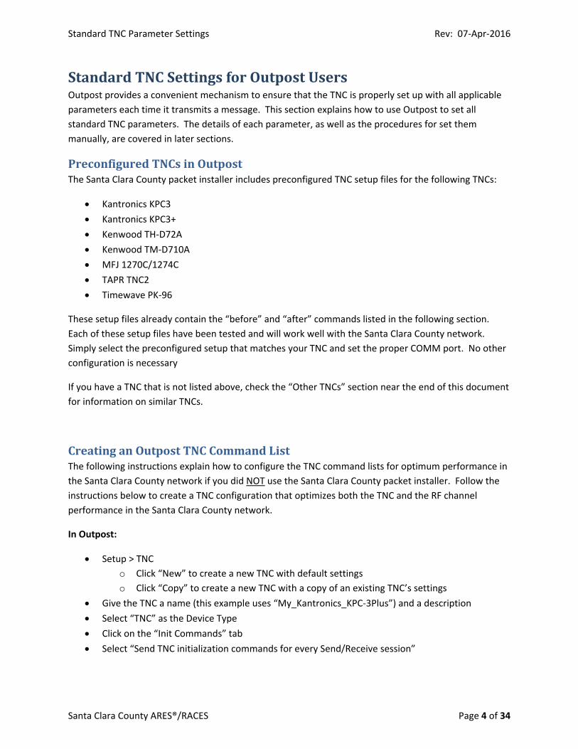
CreatinganOutpostTNCCommandListThe following instructions explain how to configure the TNC command lists for optimum performance in
the Santa Clara County network if you did NOT use the Santa Clara County packet installer. Follow the
instructions below to create a TNC configuration that optimizes both the TNC and the RF channel
performance in the Santa Clara County network.
In Outpost:
Setup > TNC
o Click “New” to create a new TNC with default settings
o Click “Copy” to create a new TNC with a copy of an existing TNC’s settings
Give the TNC a name (this example uses “My_Kantronics_KPC‐3Plus”) and a description
Select “TNC” as the Device Type
Click on the “Init Commands” tab
Select “Send TNC initialization commands for every Send/Receive session”
Standard TNC Parameter Settings Rev: 07‐Apr‐2016
Santa Clara County ARES®/RACES Page 5 of 34
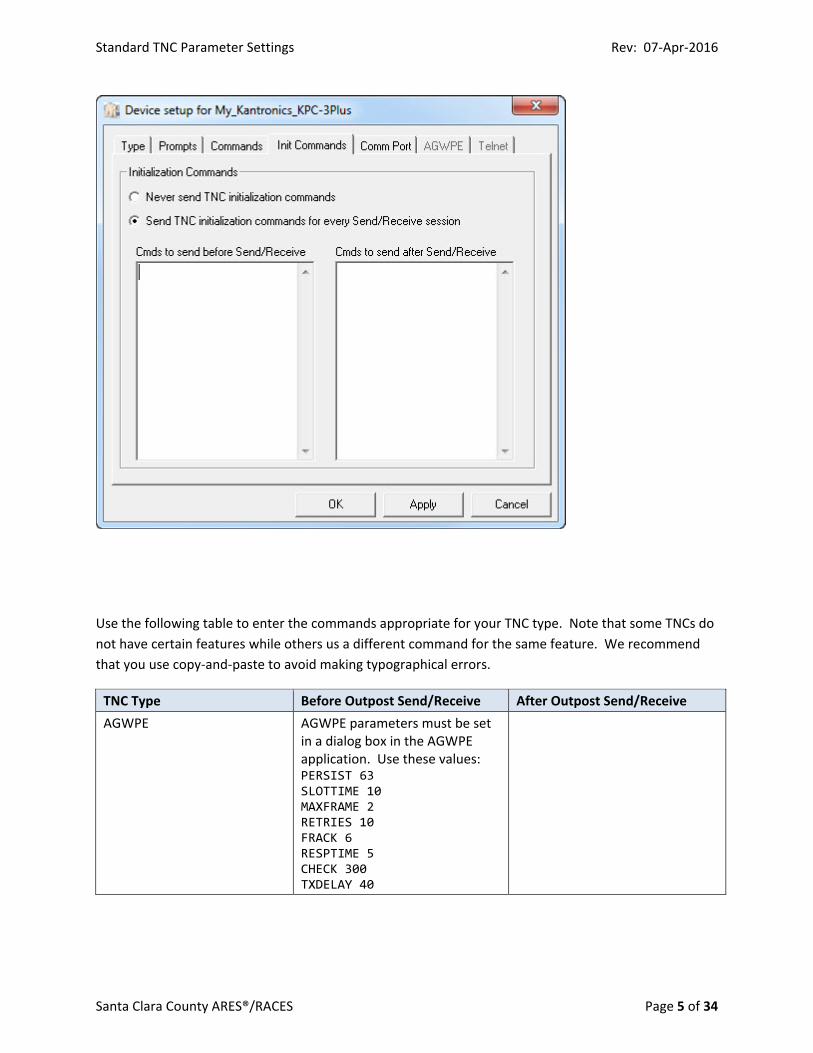
Use the following table to enter the commands appropriate for your TNC type. Note that some TNCs do
not have certain features while others us a different command for the same feature. We recommend
that you use copy‐and‐paste to avoid making typographical errors.
TNC Type Before Outpost Send/Receive After Outpost Send/Receive
AGWPE AGWPE parameters must be set in a dialog box in the AGWPE application. Use these values: PERSIST 63 SLOTTIME 10 MAXFRAME 2 RETRIES 10 FRACK 6 RESPTIME 5 CHECK 300 TXDELAY 40
Standard TNC Parameter Settings Rev: 07‐Apr‐2016
Santa Clara County ARES®/RACES Page 6 of 34
TNC Type Before Outpost Send/Receive After Outpost Send/Receive
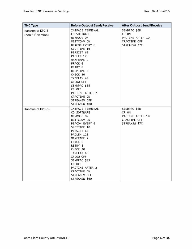
Kantronics KPC‐3 (non‐“+” version)
INTFACE TERMINAL CD SOFTWARE NEWMODE ON 8BITCONV ON BEACON EVERY 0 SLOTTIME 10 PERSIST 63 PACLEN 128 MAXFRAME 2 FRACK 6 RETRY 8 RESPTIME 5 CHECK 30 TXDELAY 40 XFLOW OFF SENDPAC $05 CR OFF PACTIME AFTER 2 CPACTIME ON STREAMEV OFF STREAMSW $00
SENDPAC $0D CR ON PACTIME AFTER 10 CPACTIME OFF STREAMSW $7C
Kantronics KPC‐3+ INTFACE TERMINAL CD SOFTWARE NEWMODE ON 8BITCONV ON BEACON EVERY 0 SLOTTIME 10 PERSIST 63 PACLEN 128 MAXFRAME 2 FRACK 6 RETRY 8 CHECK 30 TXDELAY 40 XFLOW OFF SENDPAC $05 CR OFF PACTIME AFTER 2 CPACTIME ON STREAMEV OFF STREAMSW $00
SENDPAC $0D CR ON PACTIME AFTER 10 CPACTIME OFF STREAMSW $7C
Standard TNC Parameter Settings Rev: 07‐Apr‐2016
Santa Clara County ARES®/RACES Page 7 of 34
TNC Type Before Outpost Send/Receive After Outpost Send/Receive
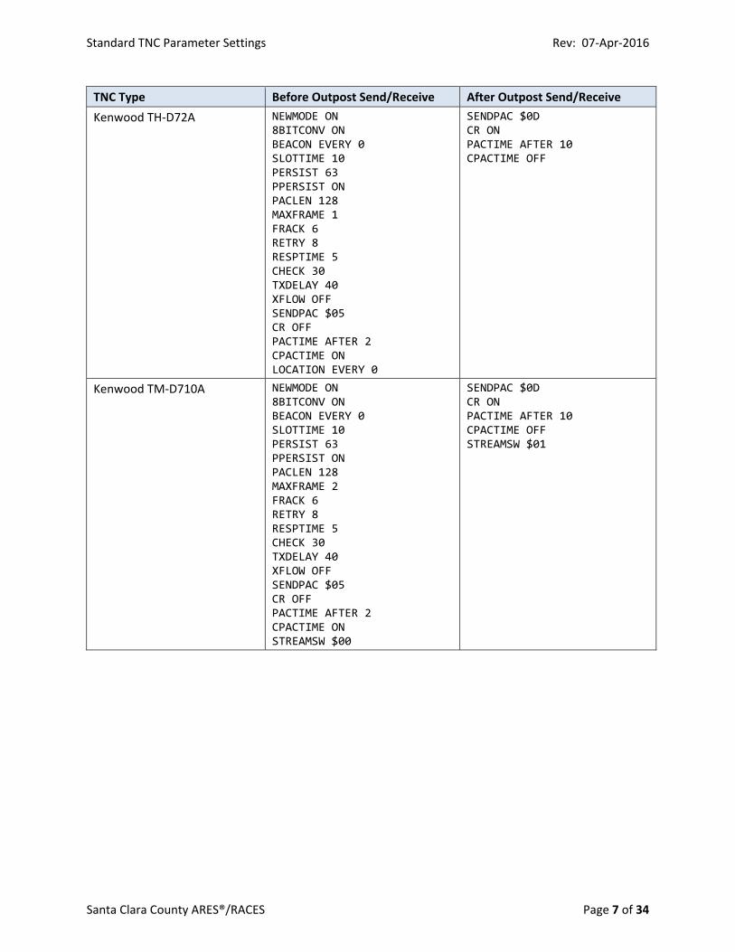
Kenwood TH‐D72A NEWMODE ON 8BITCONV ON BEACON EVERY 0 SLOTTIME 10 PERSIST 63 PPERSIST ON PACLEN 128 MAXFRAME 1 FRACK 6 RETRY 8 RESPTIME 5 CHECK 30 TXDELAY 40 XFLOW OFF SENDPAC $05 CR OFF PACTIME AFTER 2 CPACTIME ON LOCATION EVERY 0
SENDPAC $0D CR ON PACTIME AFTER 10 CPACTIME OFF
Kenwood TM‐D710A NEWMODE ON 8BITCONV ON BEACON EVERY 0 SLOTTIME 10 PERSIST 63 PPERSIST ON PACLEN 128 MAXFRAME 2 FRACK 6 RETRY 8 RESPTIME 5 CHECK 30 TXDELAY 40 XFLOW OFF SENDPAC $05 CR OFF PACTIME AFTER 2 CPACTIME ON STREAMSW $00
SENDPAC $0D CR ON PACTIME AFTER 10 CPACTIME OFF STREAMSW $01
Standard TNC Parameter Settings Rev: 07‐Apr‐2016
Santa Clara County ARES®/RACES Page 8 of 34
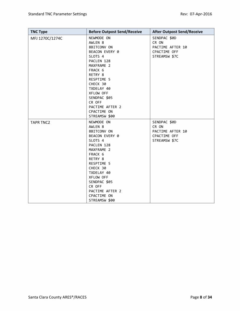
TNC Type Before Outpost Send/Receive After Outpost Send/Receive
MFJ 1270C/1274C NEWMODE ON AWLEN 8 8BITCONV ON BEACON EVERY 0 SLOTS 4 PACLEN 128 MAXFRAME 2 FRACK 6 RETRY 8 RESPTIME 5 CHECK 30 TXDELAY 40 XFLOW OFF SENDPAC $05 CR OFF PACTIME AFTER 2 CPACTIME ON STREAMSW $00
SENDPAC $0D CR ON PACTIME AFTER 10 CPACTIME OFF STREAMSW $7C
TAPR TNC2 NEWMODE ON AWLEN 8 8BITCONV ON BEACON EVERY 0 SLOTS 4 PACLEN 128 MAXFRAME 2 FRACK 6 RETRY 8 RESPTIME 5 CHECK 30 TXDELAY 40 XFLOW OFF SENDPAC $05 CR OFF PACTIME AFTER 2 CPACTIME ON STREAMSW $00
SENDPAC $0D CR ON PACTIME AFTER 10 CPACTIME OFF STREAMSW $7C
Standard TNC Parameter Settings Rev: 07‐Apr‐2016
Santa Clara County ARES®/RACES Page 9 of 34
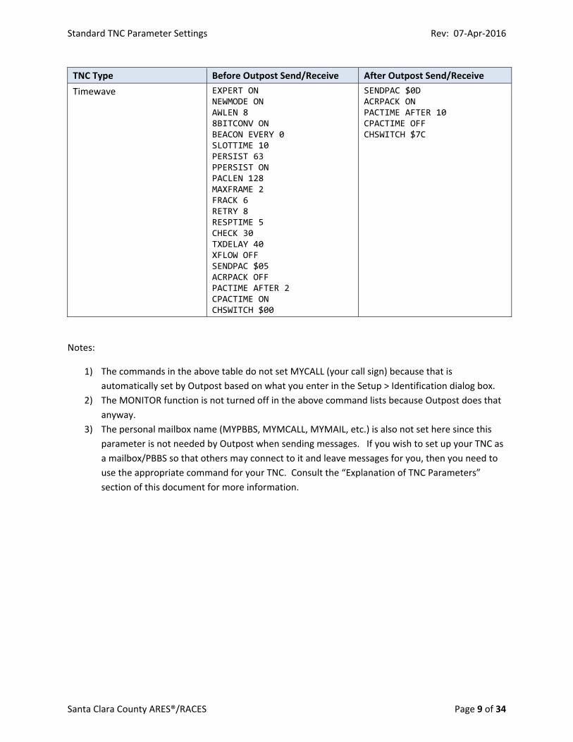
TNC Type Before Outpost Send/Receive After Outpost Send/Receive
Timewave EXPERT ON NEWMODE ON AWLEN 8 8BITCONV ON BEACON EVERY 0 SLOTTIME 10 PERSIST 63 PPERSIST ON PACLEN 128 MAXFRAME 2 FRACK 6 RETRY 8 RESPTIME 5 CHECK 30 TXDELAY 40 XFLOW OFF SENDPAC $05 ACRPACK OFF PACTIME AFTER 2 CPACTIME ON CHSWITCH $00
SENDPAC $0D ACRPACK ON PACTIME AFTER 10 CPACTIME OFF CHSWITCH $7C
Notes:
1) The commands in the above table do not set MYCALL (your call sign) because that is
automatically set by Outpost based on what you enter in the Setup > Identification dialog box.
2) The MONITOR function is not turned off in the above command lists because Outpost does that
anyway.
3) The personal mailbox name (MYPBBS, MYMCALL, MYMAIL, etc.) is also not set here since this
parameter is not needed by Outpost when sending messages. If you wish to set up your TNC as
a mailbox/PBBS so that others may connect to it and leave messages for you, then you need to
use the appropriate command for your TNC. Consult the “Explanation of TNC Parameters”
section of this document for more information.
Standard TNC Parameter Settings Rev: 07‐Apr‐2016
Santa Clara County ARES®/RACES Page 10 of 34
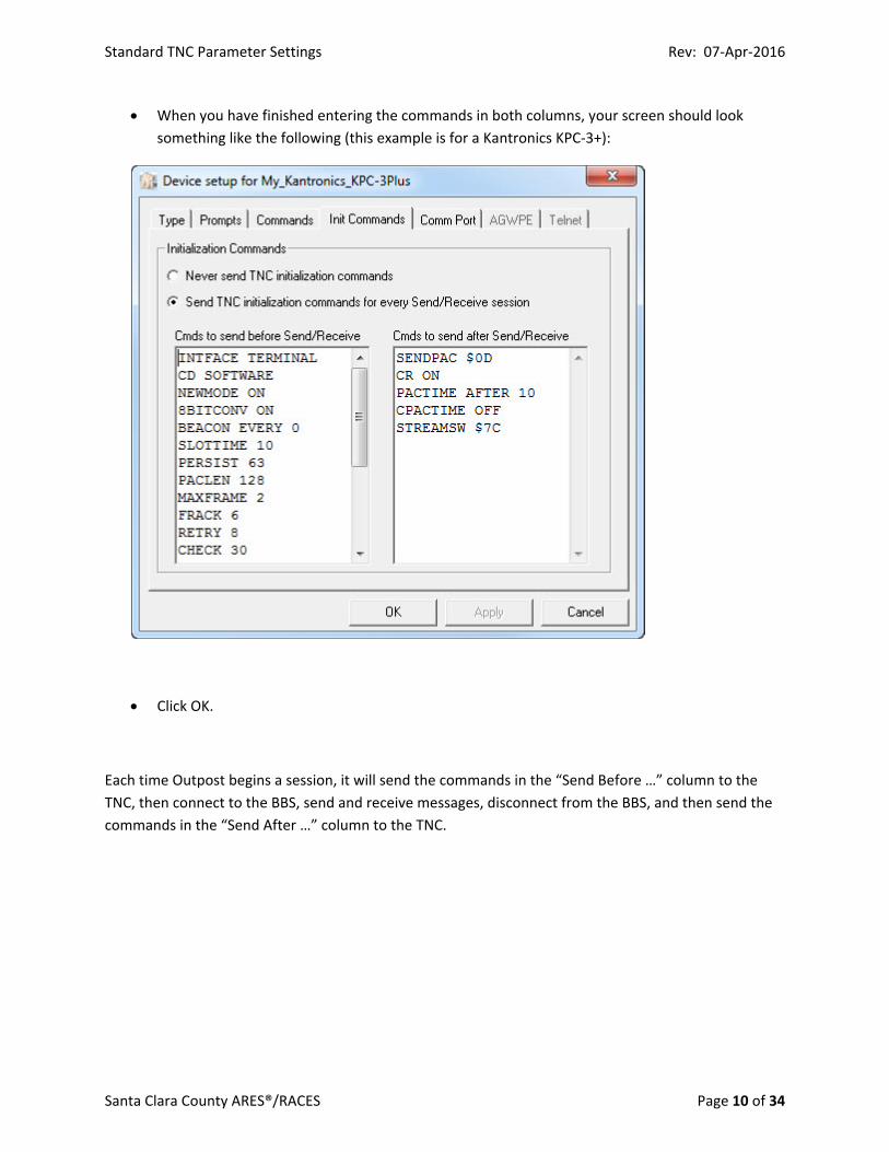
When you have finished entering the commands in both columns, your screen should look
something like the following (this example is for a Kantronics KPC‐3+):
Click OK.
Each time Outpost begins a session, it will send the commands in the “Send Before …” column to the
TNC, then connect to the BBS, send and receive messages, disconnect from the BBS, and then send the
commands in the “Send After …” column to the TNC.

Standard TNC Parameter Settings Rev: 07‐Apr‐2016
Santa Clara County ARES®/RACES Page 11 of 34
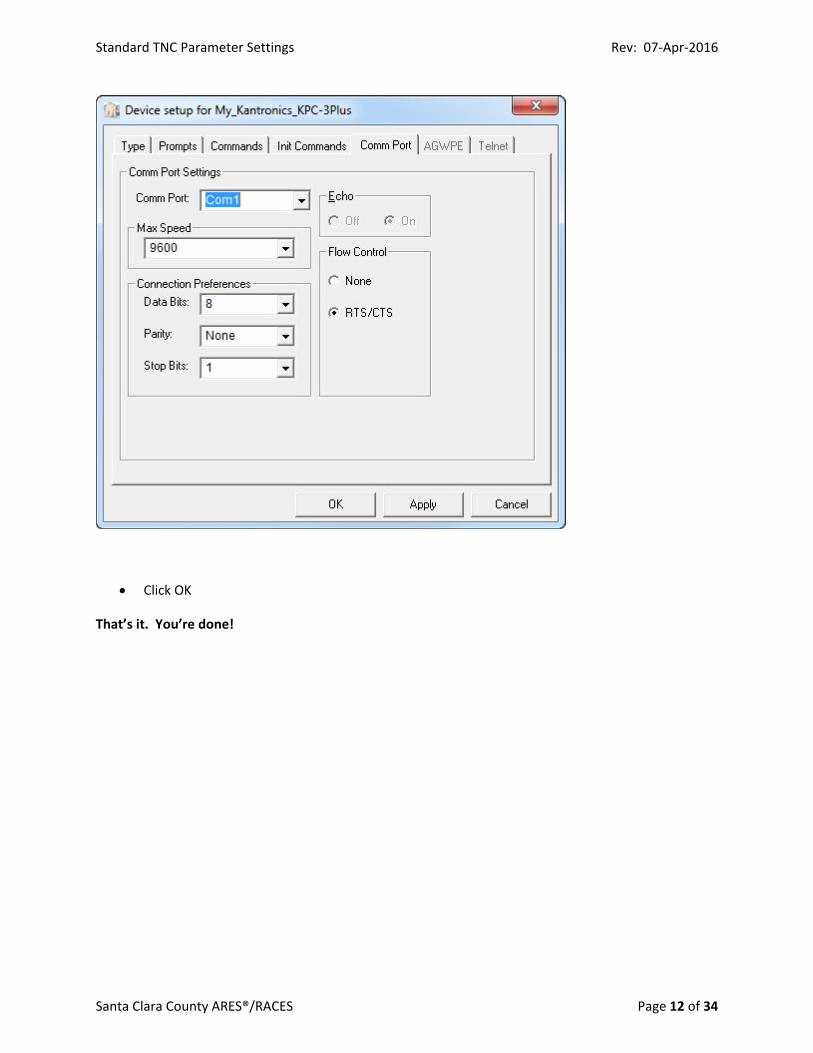
Finally, set the TNC Comm Port Parameters
o Setup > TNC > (select TNC) > Comm Port
Comm Port: Pick the correct port for your PC configuration
If unsure, check the Windows Device Manager
Max Speed: Usually 9600
Using a higher baud rate on the serial port (9600) than is used on the air
(1200) ensures that the TNC has sufficient data when assembling
outgoing packets for the maximum packet size, which increases
efficiency. It also avoids the need for the TNC to buffer incoming data,
which is important because most TNCs have limited amounts of
memory.
Data Bits: Usually 8
Parity: Usually None
Stop Bits: Usually 1
Flow Control: RTS/CTS
Flow control is important for reliable communications. It notifies the
sending side when the receiving side is ready to receive data. Hardware
flow control is the most reliable method of flow control and RTS/CTS is
the most common method of hardware flow control. Check the
documentation for your TNC to make sure it supports this method.
Setting “RTS/CTS” here matches the flow control used by Outpost to the
hardware flow control set on the TNC using the “XFLOW OFF”
command.
Note: If you use extension cables and/or adapters (DB‐9 to DB‐25) to
connect your computer’s serial port (or your USB‐to‐serial adapter) to
the TNC, make sure they are straight‐through cables/adapters for all 9
pins. This ensures that the RTS/CTS control signals are passed through.
So called “null‐modem” cables and/or adapters should not be used
since they cross some wires and short together others to simulate a
connection to a modem.
Standard TNC Parameter Settings Rev: 07‐Apr‐2016
Santa Clara County ARES®/RACES Page 12 of 34
Click OK
That’s it. You’re done!
Standard TNC Parameter Settings Rev: 07‐Apr‐2016
Santa Clara County ARES®/RACES Page 13 of 34
StandardTNCSettingsforManualBBSSessionsThe parameters listed in this section are for use by all Santa Clara County packet network users when
manually connecting to the BBS (i.e. NOT using Outpost). They are a subset of the parameters used by
Outpost users. All of these parameters should be set on any TNC used in the Santa Clara County
network. Doing so will optimize performance for manual connections.
ManualOperationsWorkflowThis workflow assumes the use of a hardware TNC, which is recommended for emergency
communications work.
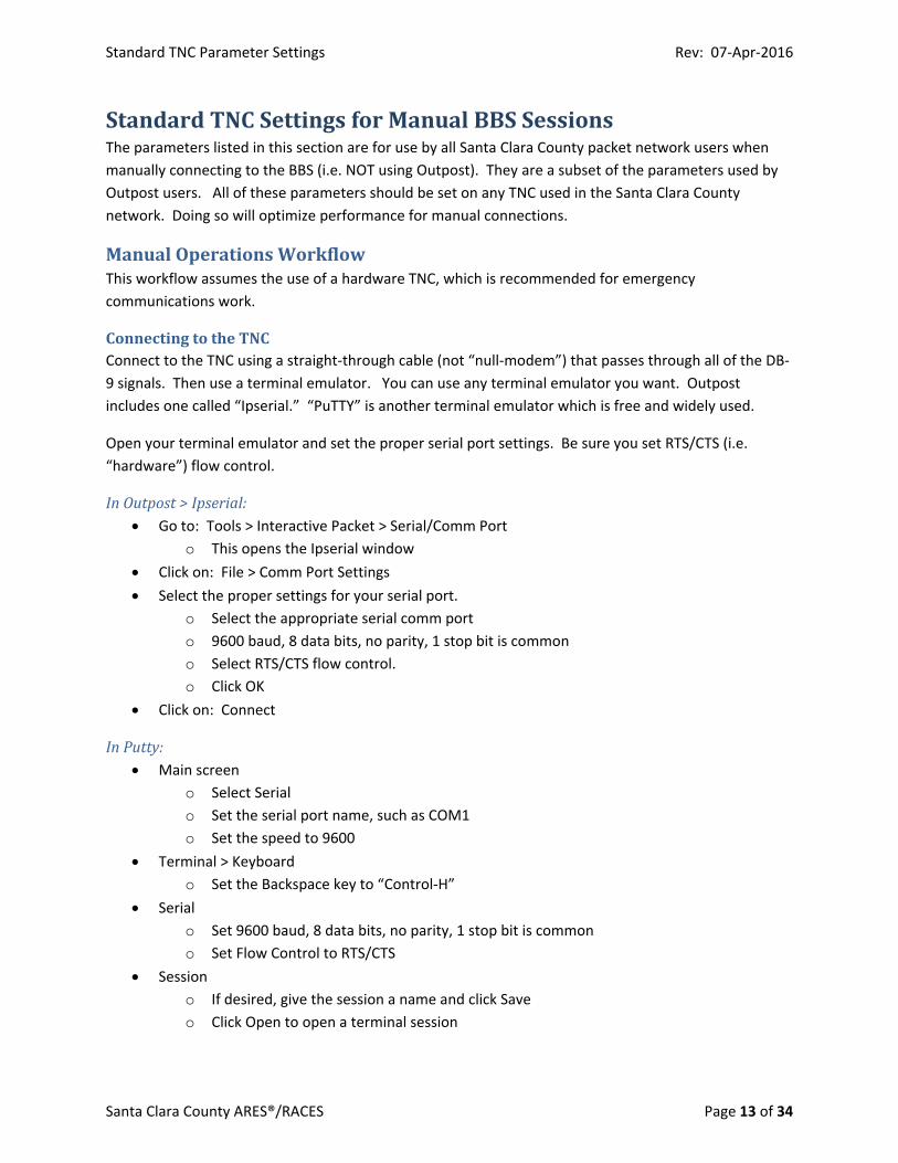
ConnectingtotheTNCConnect to the TNC using a straight‐through cable (not “null‐modem”) that passes through all of the DB‐
9 signals. Then use a terminal emulator. You can use any terminal emulator you want. Outpost
includes one called “Ipserial.” “PuTTY” is another terminal emulator which is free and widely used.
Open your terminal emulator and set the proper serial port settings. Be sure you set RTS/CTS (i.e.
“hardware”) flow control.
InOutpost>Ipserial: Go to: Tools > Interactive Packet > Serial/Comm Port
o This opens the Ipserial window
Click on: File > Comm Port Settings
Select the proper settings for your serial port.
o Select the appropriate serial comm port
o 9600 baud, 8 data bits, no parity, 1 stop bit is common
o Select RTS/CTS flow control.
o Click OK
Click on: Connect
InPutty: Main screen
o Select Serial
o Set the serial port name, such as COM1
o Set the speed to 9600
Terminal > Keyboard
o Set the Backspace key to “Control‐H”
Serial
o Set 9600 baud, 8 data bits, no parity, 1 stop bit is common
o Set Flow Control to RTS/CTS
Session
o If desired, give the session a name and click Save
o Click Open to open a terminal session
Standard TNC Parameter Settings Rev: 07‐Apr‐2016
Santa Clara County ARES®/RACES Page 14 of 34
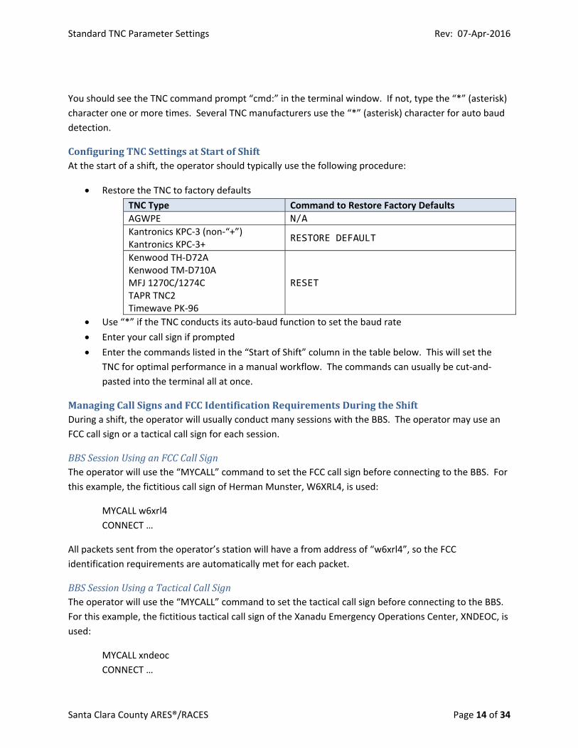
You should see the TNC command prompt “cmd:” in the terminal window. If not, type the “*” (asterisk)
character one or more times. Several TNC manufacturers use the “*” (asterisk) character for auto baud
detection.
ConfiguringTNCSettingsatStartofShiftAt the start of a shift, the operator should typically use the following procedure:
Restore the TNC to factory defaults
TNC Type Command to Restore Factory Defaults
AGWPE N/A
Kantronics KPC‐3 (non‐“+”) Kantronics KPC‐3+
RESTORE DEFAULT
Kenwood TH‐D72A Kenwood TM‐D710A MFJ 1270C/1274C TAPR TNC2 Timewave PK‐96
RESET
Use “*” if the TNC conducts its auto‐baud function to set the baud rate
Enter your call sign if prompted
Enter the commands listed in the “Start of Shift” column in the table below. This will set the
TNC for optimal performance in a manual workflow. The commands can usually be cut‐and‐
pasted into the terminal all at once.
ManagingCallSignsandFCCIdentificationRequirementsDuringtheShiftDuring a shift, the operator will usually conduct many sessions with the BBS. The operator may use an
FCC call sign or a tactical call sign for each session.
BBSSessionUsinganFCCCallSignThe operator will use the “MYCALL” command to set the FCC call sign before connecting to the BBS. For
this example, the fictitious call sign of Herman Munster, W6XRL4, is used:
MYCALL w6xrl4
CONNECT …
All packets sent from the operator’s station will have a from address of “w6xrl4”, so the FCC
identification requirements are automatically met for each packet.
BBSSessionUsingaTacticalCallSignThe operator will use the “MYCALL” command to set the tactical call sign before connecting to the BBS.
For this example, the fictitious tactical call sign of the Xanadu Emergency Operations Center, XNDEOC, is
used:
MYCALL xndeoc
CONNECT …
Standard TNC Parameter Settings Rev: 07‐Apr‐2016
Santa Clara County ARES®/RACES Page 15 of 34
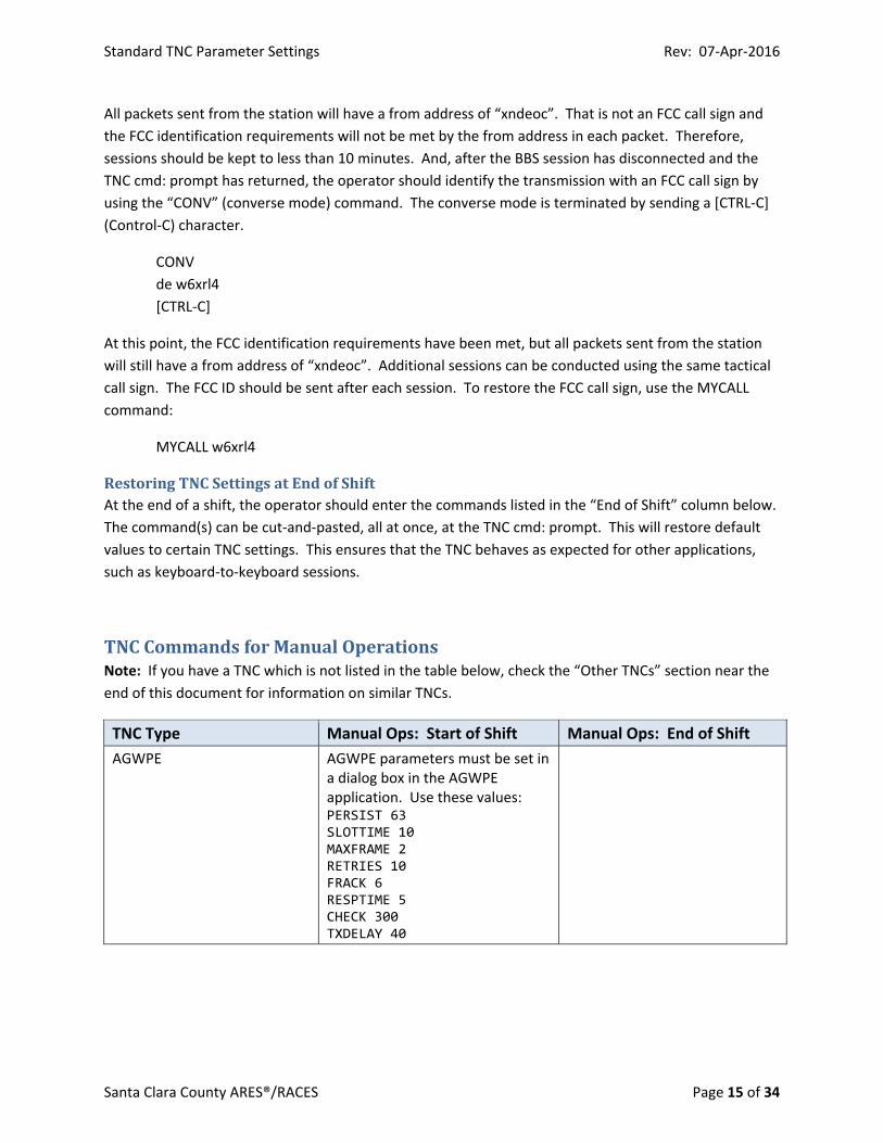
All packets sent from the station will have a from address of “xndeoc”. That is not an FCC call sign and
the FCC identification requirements will not be met by the from address in each packet. Therefore,
sessions should be kept to less than 10 minutes. And, after the BBS session has disconnected and the
TNC cmd: prompt has returned, the operator should identify the transmission with an FCC call sign by
using the “CONV” (converse mode) command. The converse mode is terminated by sending a [CTRL‐C]
(Control‐C) character.
CONV
de w6xrl4
[CTRL‐C]
At this point, the FCC identification requirements have been met, but all packets sent from the station
will still have a from address of “xndeoc”. Additional sessions can be conducted using the same tactical
call sign. The FCC ID should be sent after each session. To restore the FCC call sign, use the MYCALL
command:
MYCALL w6xrl4
RestoringTNCSettingsatEndofShiftAt the end of a shift, the operator should enter the commands listed in the “End of Shift” column below.
The command(s) can be cut‐and‐pasted, all at once, at the TNC cmd: prompt. This will restore default
values to certain TNC settings. This ensures that the TNC behaves as expected for other applications,
such as keyboard‐to‐keyboard sessions.
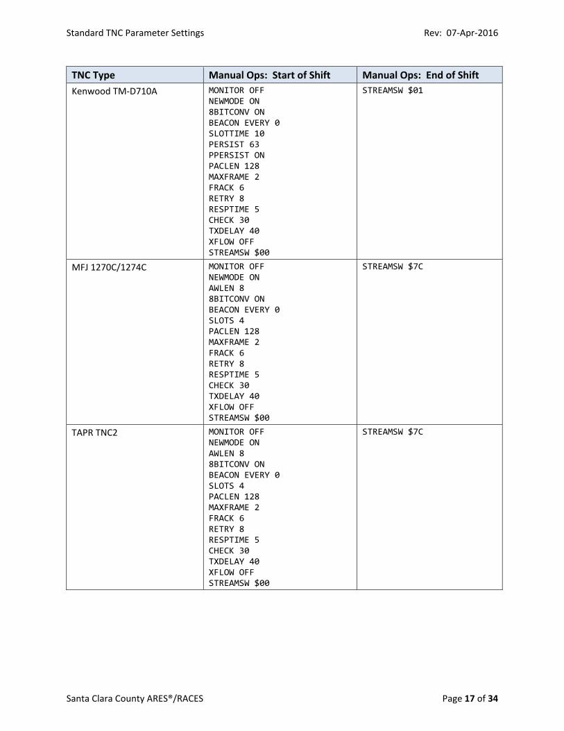
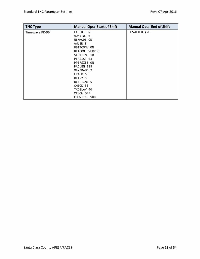
TNCCommandsforManualOperationsNote: If you have a TNC which is not listed in the table below, check the “Other TNCs” section near the
end of this document for information on similar TNCs.
TNC Type Manual Ops: Start of Shift Manual Ops: End of Shift
AGWPE AGWPE parameters must be set in a dialog box in the AGWPE application. Use these values: PERSIST 63 SLOTTIME 10 MAXFRAME 2 RETRIES 10 FRACK 6 RESPTIME 5 CHECK 300 TXDELAY 40
Standard TNC Parameter Settings Rev: 07‐Apr‐2016
Santa Clara County ARES®/RACES Page 16 of 34
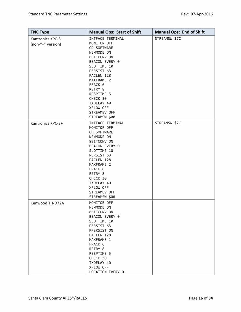
TNC Type Manual Ops: Start of Shift Manual Ops: End of Shift
Kantronics KPC‐3 (non‐“+” version)
INTFACE TERMINAL MONITOR OFF CD SOFTWARE NEWMODE ON 8BITCONV ON BEACON EVERY 0 SLOTTIME 10 PERSIST 63 PACLEN 128 MAXFRAME 2 FRACK 6 RETRY 8 RESPTIME 5 CHECK 30 TXDELAY 40 XFLOW OFF STREAMEV OFF STREAMSW $00
STREAMSW $7C
Kantronics KPC‐3+ INTFACE TERMINAL MONITOR OFF CD SOFTWARE NEWMODE ON 8BITCONV ON BEACON EVERY 0 SLOTTIME 10 PERSIST 63 PACLEN 128 MAXFRAME 2 FRACK 6 RETRY 8 CHECK 30 TXDELAY 40 XFLOW OFF STREAMEV OFF STREAMSW $00
STREAMSW $7C
Kenwood TH‐D72A MONITOR OFF NEWMODE ON 8BITCONV ON BEACON EVERY 0 SLOTTIME 10 PERSIST 63 PPERSIST ON PACLEN 128 MAXFRAME 1 FRACK 6 RETRY 8 RESPTIME 5 CHECK 30 TXDELAY 40 XFLOW OFF LOCATION EVERY 0
Standard TNC Parameter Settings Rev: 07‐Apr‐2016
Santa Clara County ARES®/RACES Page 17 of 34
TNC Type Manual Ops: Start of Shift Manual Ops: End of Shift
Kenwood TM‐D710A MONITOR OFF NEWMODE ON 8BITCONV ON BEACON EVERY 0 SLOTTIME 10 PERSIST 63 PPERSIST ON PACLEN 128 MAXFRAME 2 FRACK 6 RETRY 8 RESPTIME 5 CHECK 30 TXDELAY 40 XFLOW OFF STREAMSW $00
STREAMSW $01
MFJ 1270C/1274C MONITOR OFF NEWMODE ON AWLEN 8 8BITCONV ON BEACON EVERY 0 SLOTS 4 PACLEN 128 MAXFRAME 2 FRACK 6 RETRY 8 RESPTIME 5 CHECK 30 TXDELAY 40 XFLOW OFF STREAMSW $00
STREAMSW $7C
TAPR TNC2 MONITOR OFF NEWMODE ON AWLEN 8 8BITCONV ON BEACON EVERY 0 SLOTS 4 PACLEN 128 MAXFRAME 2 FRACK 6 RETRY 8 RESPTIME 5 CHECK 30 TXDELAY 40 XFLOW OFF STREAMSW $00
STREAMSW $7C
Standard TNC Parameter Settings Rev: 07‐Apr‐2016
Santa Clara County ARES®/RACES Page 18 of 34
TNC Type Manual Ops: Start of Shift Manual Ops: End of Shift
Timewave PK‐96 EXPERT ON MONITOR 0 NEWMODE ON AWLEN 8 8BITCONV ON BEACON EVERY 0 SLOTTIME 10 PERSIST 63 PPERSIST ON PACLEN 128 MAXFRAME 2 FRACK 6 RETRY 8 RESPTIME 5 CHECK 30 TXDELAY 40 XFLOW OFF CHSWITCH $00
CHSWITCH $7C
Standard TNC Parameter Settings Rev: 07‐Apr‐2016
Santa Clara County ARES®/RACES Page 19 of 34
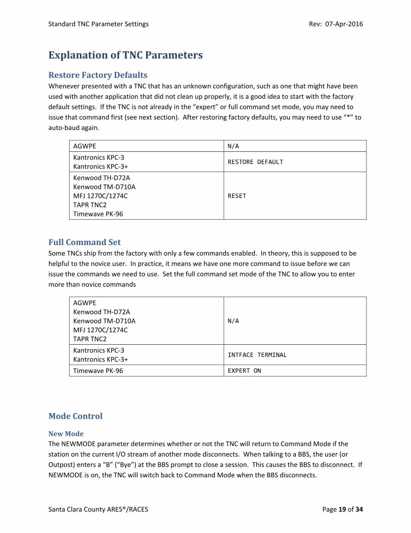
ExplanationofTNCParameters
RestoreFactoryDefaultsWhenever presented with a TNC that has an unknown configuration, such as one that might have been
used with another application that did not clean up properly, it is a good idea to start with the factory
default settings. If the TNC is not already in the “expert” or full command set mode, you may need to
issue that command first (see next section). After restoring factory defaults, you may need to use “*” to
auto‐baud again.
AGWPE N/A
Kantronics KPC‐3 Kantronics KPC‐3+
RESTORE DEFAULT
Kenwood TH‐D72A Kenwood TM‐D710A MFJ 1270C/1274C TAPR TNC2 Timewave PK‐96
RESET
FullCommandSetSome TNCs ship from the factory with only a few commands enabled. In theory, this is supposed to be
helpful to the novice user. In practice, it means we have one more command to issue before we can
issue the commands we need to use. Set the full command set mode of the TNC to allow you to enter
more than novice commands
AGWPE Kenwood TH‐D72A Kenwood TM‐D710A MFJ 1270C/1274C TAPR TNC2
N/A
Kantronics KPC‐3 Kantronics KPC‐3+
INTFACE TERMINAL
Timewave PK‐96 EXPERT ON
ModeControl
NewModeThe NEWMODE parameter determines whether or not the TNC will return to Command Mode if the
station on the current I/O stream of another mode disconnects. When talking to a BBS, the user (or
Outpost) enters a “B” (“Bye”) at the BBS prompt to close a session. This causes the BBS to disconnect. If
NEWMODE is on, the TNC will switch back to Command Mode when the BBS disconnects.
Standard TNC Parameter Settings Rev: 07‐Apr‐2016
Santa Clara County ARES®/RACES Page 20 of 34
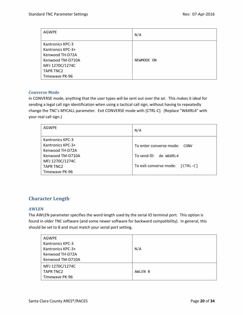
AGWPE
N/A
Kantronics KPC‐3 Kantronics KPC‐3+ Kenwood TH‐D72A Kenwood TM‐D710A MFJ 1270C/1274C TAPR TNC2 Timewave PK‐96
NEWMODE ON
ConverseModeIn CONVERSE mode, anything that the user types will be sent out over the air. This makes it ideal for
sending a legal call sign identification when using a tactical call sign, without having to repeatedly
change the TNC’s MYCALL parameter. Exit CONVERSE mode with [CTRL‐C]. (Replace “W6XRL4” with
your real call sign.)
AGWPE
N/A
Kantronics KPC‐3 Kantronics KPC‐3+ Kenwood TH‐D72A Kenwood TM‐D710A MFJ 1270C/1274C TAPR TNC2 Timewave PK‐96
To enter converse mode: CONV
To send ID: de W6XRL4
To exit converse mode: [CTRL‐C]
CharacterLength
AWLENThe AWLEN parameter specifies the word length used by the serial IO terminal port. This option is
found in older TNC software (and some newer software for backward compatibility). In general, this
should be set to 8 and must match your serial port setting.
AGWPE Kantronics KPC‐3 Kantronics KPC‐3+ Kenwood TH‐D72A Kenwood TM‐D710A
N/A
MFJ 1270C/1274C TAPR TNC2 Timewave PK‐96
AWLEN 8
Standard TNC Parameter Settings Rev: 07‐Apr‐2016
Santa Clara County ARES®/RACES Page 21 of 34
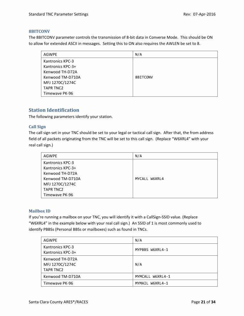
8BITCONVThe 8BITCONV parameter controls the transmission of 8‐bit data in Converse Mode. This should be ON
to allow for extended ASCII in messages. Setting this to ON also requires the AWLEN be set to 8.
AGWPE N/A
Kantronics KPC‐3 Kantronics KPC‐3+ Kenwood TH‐D72A Kenwood TM‐D710A MFJ 1270C/1274C TAPR TNC2 Timewave PK‐96
8BITCONV
StationIdentificationThe following parameters identify your station.
CallSignThe call sign set in your TNC should be set to your legal or tactical call sign. After that, the from address
field of all packets originating from the TNC will be set to this call sign. (Replace “W6XRL4” with your
real call sign.)
AGWPE N/A
Kantronics KPC‐3 Kantronics KPC‐3+ Kenwood TH‐D72A Kenwood TM‐D710A MFJ 1270C/1274C TAPR TNC2 Timewave PK‐96
MYCALL W6XRL4
MailboxIDIf you’re running a mailbox on your TNC, you will identify it with a CallSign‐SSID value. (Replace
“W6XRL4” in the example below with your real call sign.) An SSID of 1 is most commonly used to
identify PBBSs (Personal BBSs or mailboxes) such as found in TNCs.
AGWPE N/A
Kantronics KPC‐3 Kantronics KPC‐3+
MYPBBS W6XRL4‐1
Kenwood TH‐D72A MFJ 1270C/1274C TAPR TNC2
N/A
Kenwood TM‐D710A MYMCALL W6XRL4‐1
Timewave PK‐96 MYMAIL W6XRL4‐1

Standard TNC Parameter Settings Rev: 07‐Apr‐2016
Santa Clara County ARES®/RACES Page 22 of 34
BeaconIntervalThe BEACON parameter controls how often the TNC sends out an ID packet. Do NOT enable beaconing
unless you are running a mailbox or other function on your TNC to which others will connect.
To turn off beaconing:
AGWPE N/A
Kantronics KPC‐3 Kantronics KPC‐3+ Kenwood TH‐D72A Kenwood TM‐D710A MFJ 1270C/1274C TAPR TNC2 Timewave PK‐96
BEACON EVERY 0
Note: Never beacon on a BBS access frequency. The BBS frequencies in use in the Santa Clara County
network are coordinated frequencies. You should never run your own BBS, mailbox, digipeater or node
on these frequencies. Select a suitable alternate frequency from the NCPA band plan.
If you run your own BBS, mailbox, digipeater or node (on a different frequency from the county BBSs!),
you may want to beacon so that your users know that your station is up and available for them to use.
But beaconing too frequently is a waste of bandwidth and is frowned upon. A good compromise is to
set your beacon timer to 30 minutes or longer. Be aware that different manufacturers use different
increments of time. Kantronics uses increments of minutes. Kenwood, MFJ, TAPR, Timewave and
Kenwood use increments of 10 secs. The following commands all set the beacon interval to 30 minutes.
To turn on beaconing when NOT on a BBS frequency:
AGWPE N/A
Kantronics KPC‐3 Kantronics KPC‐3+
BEACON EVERY 30
Kenwood TH‐D72A Kenwood TM‐D710A MFJ 1270C/1274C TAPR TNC2 Timewave PK‐96
BEACON EVERY 180
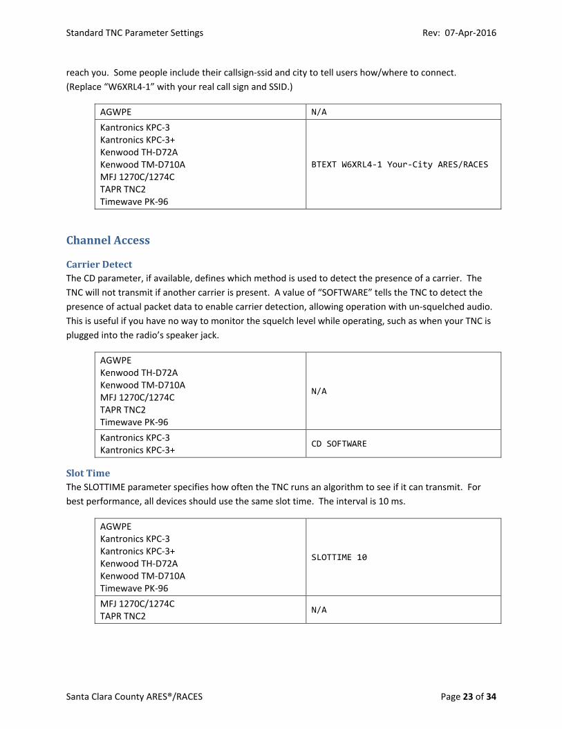
BeaconTextThe BTEXT parameter controls the content of the beacons. If beaconing is turned off, then the beacon
text does not matter. If you must beacon, do it on a different frequency from the county BBSs and then
keep your beacon text as short as possible, but provide enough information so that people know how to
Standard TNC Parameter Settings Rev: 07‐Apr‐2016
Santa Clara County ARES®/RACES Page 23 of 34
reach you. Some people include their callsign‐ssid and city to tell users how/where to connect.
(Replace “W6XRL4‐1” with your real call sign and SSID.)
AGWPE N/A
Kantronics KPC‐3 Kantronics KPC‐3+ Kenwood TH‐D72A Kenwood TM‐D710A MFJ 1270C/1274C TAPR TNC2 Timewave PK‐96
BTEXT W6XRL4‐1 Your‐City ARES/RACES
ChannelAccess
CarrierDetectThe CD parameter, if available, defines which method is used to detect the presence of a carrier. The
TNC will not transmit if another carrier is present. A value of “SOFTWARE” tells the TNC to detect the
presence of actual packet data to enable carrier detection, allowing operation with un‐squelched audio.
This is useful if you have no way to monitor the squelch level while operating, such as when your TNC is
plugged into the radio’s speaker jack.
AGWPE Kenwood TH‐D72A Kenwood TM‐D710A MFJ 1270C/1274C TAPR TNC2 Timewave PK‐96
N/A
Kantronics KPC‐3 Kantronics KPC‐3+
CD SOFTWARE
SlotTimeThe SLOTTIME parameter specifies how often the TNC runs an algorithm to see if it can transmit. For
best performance, all devices should use the same slot time. The interval is 10 ms.
AGWPE Kantronics KPC‐3 Kantronics KPC‐3+ Kenwood TH‐D72A Kenwood TM‐D710A Timewave PK‐96
SLOTTIME 10
MFJ 1270C/1274C TAPR TNC2
N/A
Standard TNC Parameter Settings Rev: 07‐Apr‐2016
Santa Clara County ARES®/RACES Page 24 of 34
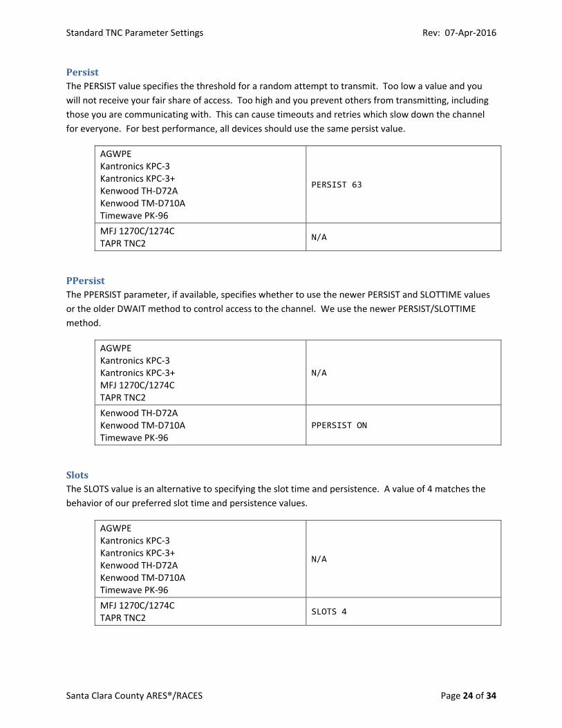
PersistThe PERSIST value specifies the threshold for a random attempt to transmit. Too low a value and you
will not receive your fair share of access. Too high and you prevent others from transmitting, including
those you are communicating with. This can cause timeouts and retries which slow down the channel
for everyone. For best performance, all devices should use the same persist value.
AGWPE Kantronics KPC‐3 Kantronics KPC‐3+ Kenwood TH‐D72A Kenwood TM‐D710A Timewave PK‐96
PERSIST 63
MFJ 1270C/1274C TAPR TNC2
N/A
PPersistThe PPERSIST parameter, if available, specifies whether to use the newer PERSIST and SLOTTIME values
or the older DWAIT method to control access to the channel. We use the newer PERSIST/SLOTTIME
method.
AGWPE Kantronics KPC‐3 Kantronics KPC‐3+ MFJ 1270C/1274C TAPR TNC2
N/A
Kenwood TH‐D72A Kenwood TM‐D710A Timewave PK‐96
PPERSIST ON
SlotsThe SLOTS value is an alternative to specifying the slot time and persistence. A value of 4 matches the
behavior of our preferred slot time and persistence values.
AGWPE Kantronics KPC‐3 Kantronics KPC‐3+ Kenwood TH‐D72A Kenwood TM‐D710A Timewave PK‐96
N/A
MFJ 1270C/1274C TAPR TNC2
SLOTS 4
Standard TNC Parameter Settings Rev: 07‐Apr‐2016
Santa Clara County ARES®/RACES Page 25 of 34
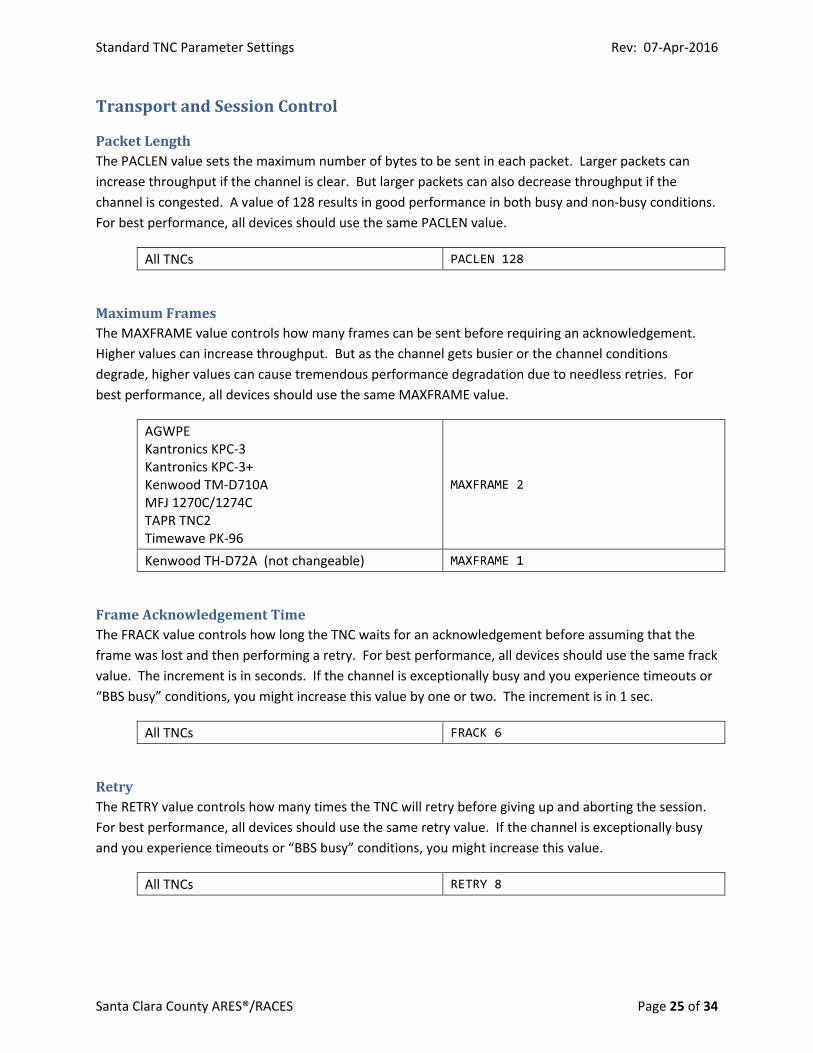
TransportandSessionControl
PacketLengthThe PACLEN value sets the maximum number of bytes to be sent in each packet. Larger packets can
increase throughput if the channel is clear. But larger packets can also decrease throughput if the
channel is congested. A value of 128 results in good performance in both busy and non‐busy conditions.
For best performance, all devices should use the same PACLEN value.
All TNCs PACLEN 128
MaximumFramesThe MAXFRAME value controls how many frames can be sent before requiring an acknowledgement.
Higher values can increase throughput. But as the channel gets busier or the channel conditions
degrade, higher values can cause tremendous performance degradation due to needless retries. For
best performance, all devices should use the same MAXFRAME value.
AGWPE Kantronics KPC‐3 Kantronics KPC‐3+ Kenwood TM‐D710A MFJ 1270C/1274C TAPR TNC2 Timewave PK‐96
MAXFRAME 2
Kenwood TH‐D72A (not changeable) MAXFRAME 1
FrameAcknowledgementTimeThe FRACK value controls how long the TNC waits for an acknowledgement before assuming that the
frame was lost and then performing a retry. For best performance, all devices should use the same frack
value. The increment is in seconds. If the channel is exceptionally busy and you experience timeouts or
“BBS busy” conditions, you might increase this value by one or two. The increment is in 1 sec.
All TNCs FRACK 6
RetryThe RETRY value controls how many times the TNC will retry before giving up and aborting the session.
For best performance, all devices should use the same retry value. If the channel is exceptionally busy
and you experience timeouts or “BBS busy” conditions, you might increase this value.
All TNCs RETRY 8
Standard TNC Parameter Settings Rev: 07‐Apr‐2016
Santa Clara County ARES®/RACES Page 26 of 34
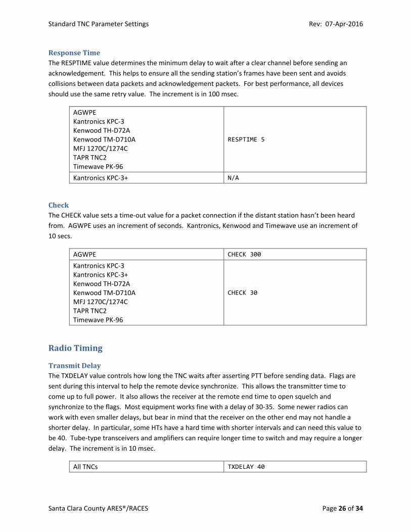
ResponseTimeThe RESPTIME value determines the minimum delay to wait after a clear channel before sending an
acknowledgement. This helps to ensure all the sending station’s frames have been sent and avoids
collisions between data packets and acknowledgement packets. For best performance, all devices
should use the same retry value. The increment is in 100 msec.
AGWPE Kantronics KPC‐3 Kenwood TH‐D72A Kenwood TM‐D710A MFJ 1270C/1274C TAPR TNC2 Timewave PK‐96
RESPTIME 5
Kantronics KPC‐3+ N/A
CheckThe CHECK value sets a time‐out value for a packet connection if the distant station hasn’t been heard
from. AGWPE uses an increment of seconds. Kantronics, Kenwood and Timewave use an increment of
10 secs.
AGWPE CHECK 300
Kantronics KPC‐3 Kantronics KPC‐3+ Kenwood TH‐D72A Kenwood TM‐D710A MFJ 1270C/1274C TAPR TNC2 Timewave PK‐96
CHECK 30
RadioTiming
TransmitDelayThe TXDELAY value controls how long the TNC waits after asserting PTT before sending data. Flags are
sent during this interval to help the remote device synchronize. This allows the transmitter time to
come up to full power. It also allows the receiver at the remote end time to open squelch and
synchronize to the flags. Most equipment works fine with a delay of 30‐35. Some newer radios can
work with even smaller delays, but bear in mind that the receiver on the other end may not handle a
shorter delay. In particular, some HTs have a hard time with shorter intervals and can need this value to
be 40. Tube‐type transceivers and amplifiers can require longer time to switch and may require a longer
delay. The increment is in 10 msec.
All TNCs TXDELAY 40
Standard TNC Parameter Settings Rev: 07‐Apr‐2016
Santa Clara County ARES®/RACES Page 27 of 34
FlowControl
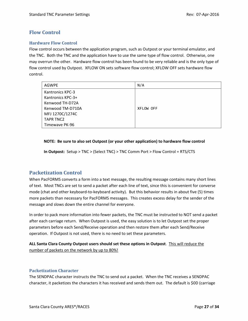
HardwareFlowControlFlow control occurs between the application program, such as Outpost or your terminal emulator, and
the TNC. Both the TNC and the application have to use the same type of flow control. Otherwise, one
may overrun the other. Hardware flow control has been found to be very reliable and is the only type of
flow control used by Outpost. XFLOW ON sets software flow control; XFLOW OFF sets hardware flow
control.
AGWPE N/A
Kantronics KPC‐3 Kantronics KPC‐3+ Kenwood TH‐D72A Kenwood TM‐D710A MFJ 1270C/1274C TAPR TNC2 Timewave PK‐96
XFLOW OFF
NOTE: Be sure to also set Outpost (or your other application) to hardware flow control
In Outpost: Setup > TNC > (Select TNC) > TNC Comm Port > Flow Control = RTS/CTS
PacketizationControlWhen PacFORMS converts a form into a text message, the resulting message contains many short lines
of text. Most TNCs are set to send a packet after each line of text, since this is convenient for converse
mode (chat and other keyboard‐to‐keyboard activity). But this behavior results in about five (5) times
more packets than necessary for PacFORMS messages. This creates excess delay for the sender of the
message and slows down the entire channel for everyone.
In order to pack more information into fewer packets, the TNC must be instructed to NOT send a packet
after each carriage return. When Outpost is used, the easy solution is to let Outpost set the proper
parameters before each Send/Receive operation and then restore them after each Send/Receive
operation. If Outpost is not used, there is no need to set these parameters.
ALL Santa Clara County Outpost users should set these options in Outpost. This will reduce the
number of packets on the network by up to 80%!
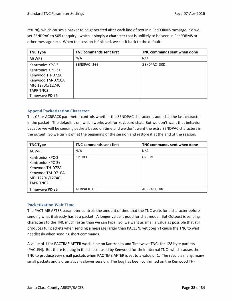
PacketizationCharacterThe SENDPAC character instructs the TNC to send out a packet. When the TNC receives a SENDPAC
character, it packetizes the characters it has received and sends them out. The default is $0D (carriage
Standard TNC Parameter Settings Rev: 07‐Apr‐2016
Santa Clara County ARES®/RACES Page 28 of 34
return), which causes a packet to be generated after each line of text in a PacFORMS message. So we
set SENDPAC to $05 (enquiry), which is simply a character that is unlikely to be seen in PacFORMS or
other message text. When the session is finished, we set it back to the default.
TNC Type TNC commands sent first TNC commands sent when done
AGWPE N/A N/A
Kantronics KPC‐3 Kantronics KPC‐3+ Kenwood TH‐D72A Kenwood TM‐D710A MFJ 1270C/1274C TAPR TNC2 Timewave PK‐96
SENDPAC $05
SENDPAC $0D
AppendPacketizationCharacterThis CR or ACRPACK parameter controls whether the SENDPAC character is added as the last character
in the packet. The default is on, which works well for keyboard chat. But we don’t want that behavior
because we will be sending packets based on time and we don’t want the extra SENDPAC characters in
the output. So we turn it off at the beginning of the session and restore it at the end of the session.
TNC Type TNC commands sent first TNC commands sent when done
AGWPE N/A N/A
Kantronics KPC‐3 Kantronics KPC‐3+ Kenwood TH‐D72A Kenwood TM‐D710A MFJ 1270C/1274C TAPR TNC2
CR OFF CR ON
Timewave PK‐96 ACRPACK OFF ACRPACK ON
PacketizationWaitTimeThe PACTIME AFTER parameter controls the amount of time that the TNC waits for a character before
sending what it already has as a packet. A longer value is good for chat mode. But Outpost is sending
characters to the TNC much faster than we can type. So, we want as small a value as possible that still
produces full packets when sending a message larger than PACLEN, yet doesn’t cause the TNC to wait
needlessly when sending short commands.
A value of 1 for PACTIME AFTER works fine on Kantronics and Timewave TNCs for 128 byte packets
(PACLEN). But there is a bug in the chipset used by Kenwood for their internal TNCs which causes the
TNC to produce very small packets when PACTIME AFTER is set to a value of 1. The result is many, many
small packets and a dramatically slower session. The bug has been confirmed on the Kenwood TH‐
Standard TNC Parameter Settings Rev: 07‐Apr‐2016
Santa Clara County ARES®/RACES Page 29 of 34
D72A, TM‐D700, TM‐D710A and TS‐2000 radios. The same behavior has also been observed on Alinco
radios using the internal EJ‐50U TNC.
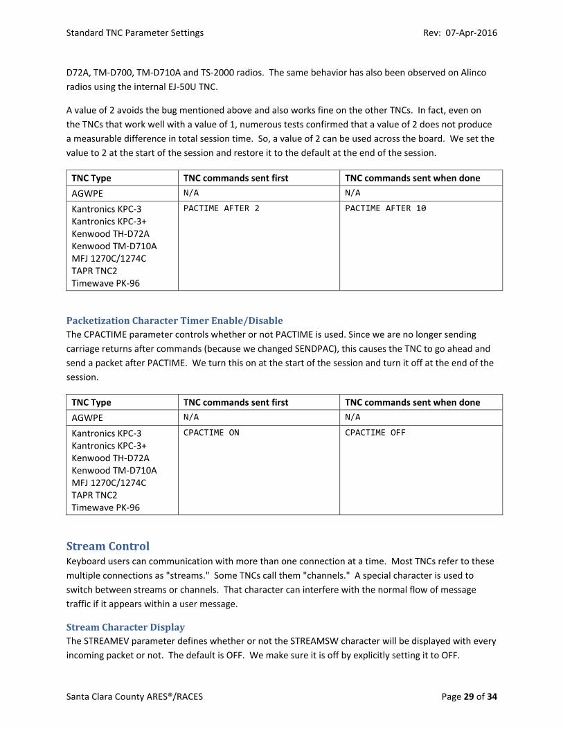
A value of 2 avoids the bug mentioned above and also works fine on the other TNCs. In fact, even on
the TNCs that work well with a value of 1, numerous tests confirmed that a value of 2 does not produce
a measurable difference in total session time. So, a value of 2 can be used across the board. We set the
value to 2 at the start of the session and restore it to the default at the end of the session.
TNC Type TNC commands sent first TNC commands sent when done
AGWPE N/A N/A
Kantronics KPC‐3 Kantronics KPC‐3+ Kenwood TH‐D72A Kenwood TM‐D710A MFJ 1270C/1274C TAPR TNC2 Timewave PK‐96
PACTIME AFTER 2 PACTIME AFTER 10
PacketizationCharacterTimerEnable/DisableThe CPACTIME parameter controls whether or not PACTIME is used. Since we are no longer sending
carriage returns after commands (because we changed SENDPAC), this causes the TNC to go ahead and
send a packet after PACTIME. We turn this on at the start of the session and turn it off at the end of the
session.
TNC Type TNC commands sent first TNC commands sent when done
AGWPE N/A N/A
Kantronics KPC‐3 Kantronics KPC‐3+ Kenwood TH‐D72A Kenwood TM‐D710A MFJ 1270C/1274C TAPR TNC2 Timewave PK‐96
CPACTIME ON CPACTIME OFF
StreamControlKeyboard users can communication with more than one connection at a time. Most TNCs refer to these
multiple connections as "streams." Some TNCs call them "channels." A special character is used to
switch between streams or channels. That character can interfere with the normal flow of message
traffic if it appears within a user message.
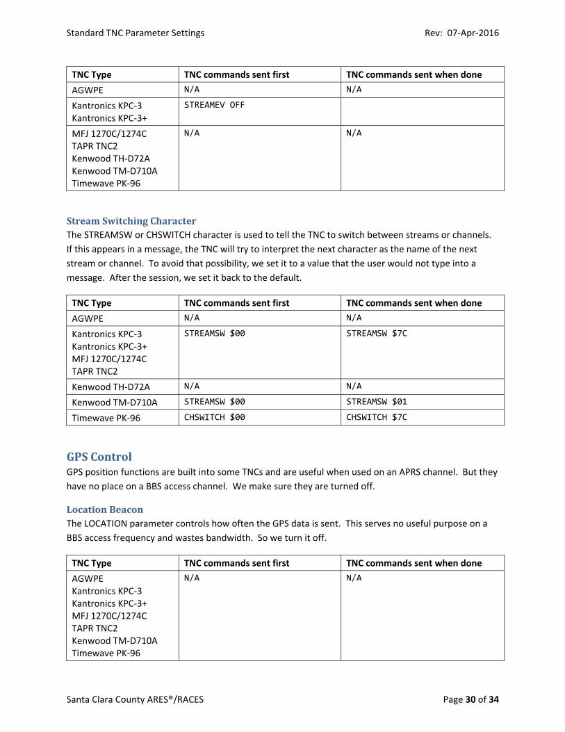
StreamCharacterDisplayThe STREAMEV parameter defines whether or not the STREAMSW character will be displayed with every
incoming packet or not. The default is OFF. We make sure it is off by explicitly setting it to OFF.
Standard TNC Parameter Settings Rev: 07‐Apr‐2016
Santa Clara County ARES®/RACES Page 30 of 34
TNC Type TNC commands sent first TNC commands sent when done
AGWPE N/A N/A
Kantronics KPC‐3 Kantronics KPC‐3+
STREAMEV OFF
MFJ 1270C/1274C TAPR TNC2 Kenwood TH‐D72A Kenwood TM‐D710A Timewave PK‐96
N/A N/A
StreamSwitchingCharacterThe STREAMSW or CHSWITCH character is used to tell the TNC to switch between streams or channels.
If this appears in a message, the TNC will try to interpret the next character as the name of the next
stream or channel. To avoid that possibility, we set it to a value that the user would not type into a
message. After the session, we set it back to the default.
TNC Type TNC commands sent first TNC commands sent when done
AGWPE N/A N/A
Kantronics KPC‐3 Kantronics KPC‐3+ MFJ 1270C/1274C TAPR TNC2
STREAMSW $00 STREAMSW $7C
Kenwood TH‐D72A N/A N/A
Kenwood TM‐D710A STREAMSW $00 STREAMSW $01
Timewave PK‐96 CHSWITCH $00 CHSWITCH $7C
GPSControlGPS position functions are built into some TNCs and are useful when used on an APRS channel. But they
have no place on a BBS access channel. We make sure they are turned off.
LocationBeaconThe LOCATION parameter controls how often the GPS data is sent. This serves no useful purpose on a
BBS access frequency and wastes bandwidth. So we turn it off.
TNC Type TNC commands sent first TNC commands sent when done
AGWPE Kantronics KPC‐3 Kantronics KPC‐3+ MFJ 1270C/1274C TAPR TNC2 Kenwood TM‐D710A Timewave PK‐96
N/A N/A

Standard TNC Parameter Settings Rev: 07‐Apr‐2016
Santa Clara County ARES®/RACES Page 31 of 34
Kenwood TH‐D72A LOCATION EVERY 0
Standard TNC Parameter Settings Rev: 07‐Apr‐2016
Santa Clara County ARES®/RACES Page 32 of 34
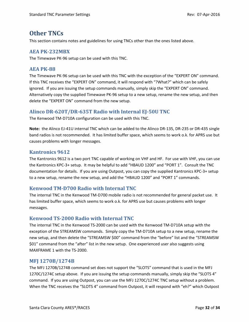
OtherTNCsThis section contains notes and guidelines for using TNCs other than the ones listed above.
AEAPK‐232MBXThe Timewave PK‐96 setup can be used with this TNC.
AEAPK‐88The Timewave PK‐96 setup can be used with this TNC with the exception of the “EXPERT ON” command.
If this TNC receives the “EXPERT ON” command, it will respond with “?What?” which can be safely
ignored. If you are issuing the setup commands manually, simply skip the “EXPERT ON” command.
Alternatively copy the supplied Timewave PK‐96 setup to a new setup, rename the new setup, and then
delete the “EXPERT ON” command from the new setup.
AlincoDR‐620T/DR‐635TRadiowithInternalEJ‐50UTNCThe Kenwood TM‐D710A configuration can be used with this TNC.
Note: the Alinco EJ‐41U internal TNC which can be added to the Alinco DR‐135, DR‐235 or DR‐435 single
band radios is not recommended. It has limited buffer space, which seems to work o.k. for APRS use but
causes problems with longer messages.
Kantronics9612The Kantronics 9612 is a two port TNC capable of working on VHF and HF. For use with VHF, you can use
the Kantronics KPC‐3+ setup. It may be helpful to add “HBAUD 1200” and “PORT 1”. Consult the TNC
documentation for details. If you are using Outpost, you can copy the supplied Kantronics KPC‐3+ setup
to a new setup, rename the new setup, and add the “HBAUD 1200” and “PORT 1” commands.
KenwoodTM‐D700RadiowithInternalTNCThe internal TNC in the Kenwood TM‐D700 mobile radio is not recommended for general packet use. It
has limited buffer space, which seems to work o.k. for APRS use but causes problems with longer
messages.
KenwoodTS‐2000RadiowithInternalTNCThe internal TNC in the Kenwood TS‐2000 can be used with the Kenwood TM‐D710A setup with the
exception of the STREAMSW commands. Simply copy the TM‐D710A setup to a new setup, rename the
new setup, and then delete the “STREAMSW $00” command from the “before” list and the “STREAMSW
$01” command from the “after” list in the new setup. One experienced user also suggests using
MAXFRAME 1 with the TS‐2000.
MFJ1270B/1274BThe MFJ 1270B/1274B command set does not support the “SLOTS” command that is used in the MFJ
1270C/1274C setup above. If you are issuing the setup commands manually, simply skip the “SLOTS 4”
command. If you are using Outpost, you can use the MFJ 1270C/1274C TNC setup without a problem.
When the TNC receives the “SLOTS 4” command from Outpost, it will respond with “eh?” which Outpost

Standard TNC Parameter Settings Rev: 07‐Apr‐2016
Santa Clara County ARES®/RACES Page 33 of 34
will ignore. If you prefer, copy the supplied MFJ 1270C/1274C setup to a new setup, rename the new
setup, and then delete the “SLOTS 4” command from the new setup.
Standard TNC Parameter Settings Rev: 07‐Apr‐2016
Santa Clara County ARES®/RACES Page 34 of 34
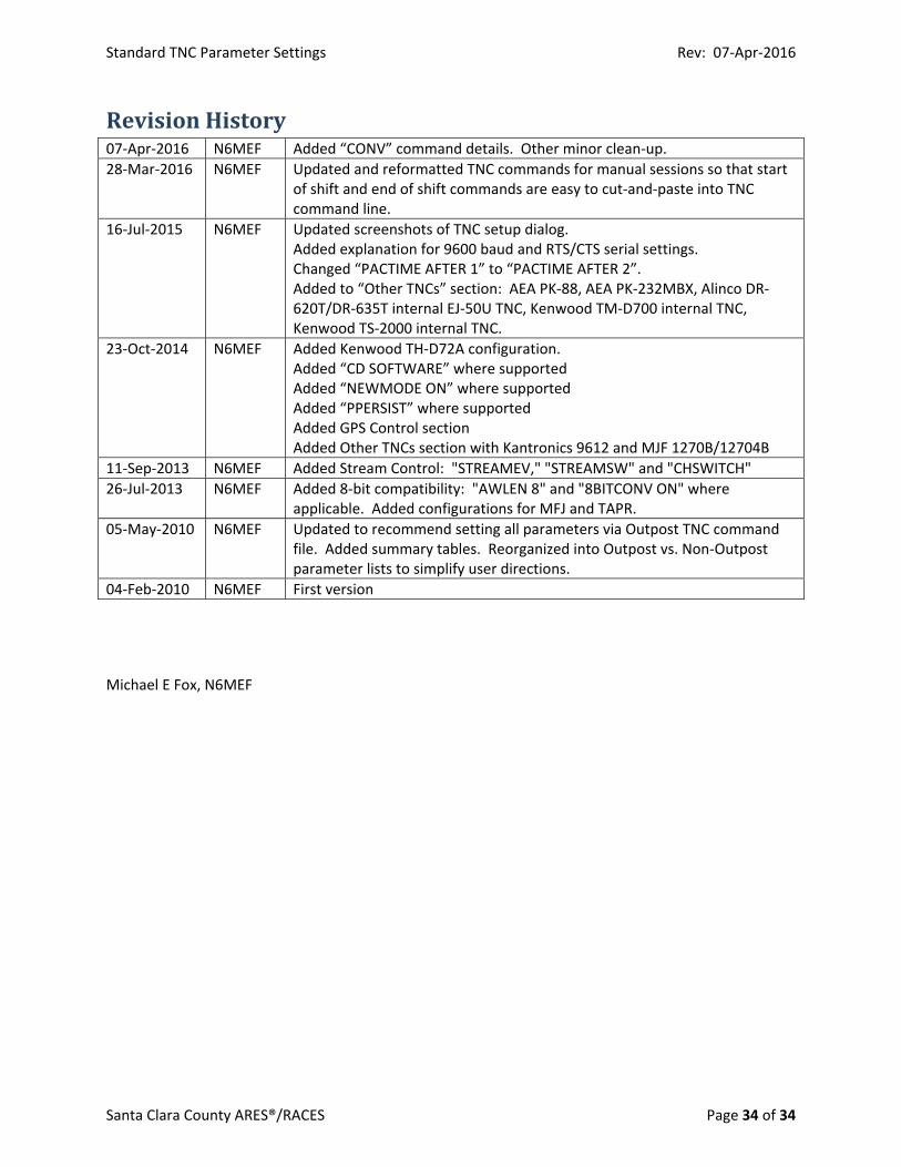
RevisionHistory07‐Apr‐2016 N6MEF Added “CONV” command details. Other minor clean‐up.
28‐Mar‐2016 N6MEF Updated and reformatted TNC commands for manual sessions so that start of shift and end of shift commands are easy to cut‐and‐paste into TNC command line.
16‐Jul‐2015 N6MEF Updated screenshots of TNC setup dialog. Added explanation for 9600 baud and RTS/CTS serial settings. Changed “PACTIME AFTER 1” to “PACTIME AFTER 2”. Added to “Other TNCs” section: AEA PK‐88, AEA PK‐232MBX, Alinco DR‐620T/DR‐635T internal EJ‐50U TNC, Kenwood TM‐D700 internal TNC, Kenwood TS‐2000 internal TNC.
23‐Oct‐2014 N6MEF Added Kenwood TH‐D72A configuration. Added “CD SOFTWARE” where supported Added “NEWMODE ON” where supported Added “PPERSIST” where supported Added GPS Control section Added Other TNCs section with Kantronics 9612 and MJF 1270B/12704B
11‐Sep‐2013 N6MEF Added Stream Control: "STREAMEV," "STREAMSW" and "CHSWITCH"
26‐Jul‐2013 N6MEF Added 8‐bit compatibility: "AWLEN 8" and "8BITCONV ON" where applicable. Added configurations for MFJ and TAPR.
05‐May‐2010 N6MEF Updated to recommend setting all parameters via Outpost TNC command file. Added summary tables. Reorganized into Outpost vs. Non‐Outpost parameter lists to simplify user directions.
04‐Feb‐2010 N6MEF First version
Michael E Fox, N6MEF