Standard Test Methods for Textile Composites - NASA Test Methods for Textile Composites ... Standard...
88
d ' NASA Contractor Report 4751 Standard Test Methods for Textile Composites John E. Masters and Marc A. Portanova Contract NAS1-19000 Prepared for Langley Research Center September 1996 https://ntrs.nasa.gov/search.jsp?R=19960054333 2018-06-04T16:18:12+00:00Z
Transcript of Standard Test Methods for Textile Composites - NASA Test Methods for Textile Composites ... Standard...

d '
NASA Contractor Report 4751
Standard Test Methods for Textile Composites
John E. Masters and Marc A. Portanova
Contract NAS1-19000Prepared for Langley Research Center
September 1996
https://ntrs.nasa.gov/search.jsp?R=19960054333 2018-06-04T16:18:12+00:00Z


NASA Contractor Report 4751
Standard Test Methods for Textile Composites
John E. Masters and Marc A. Portanova
Lockheed Martin Engineering & Sciences Company ° Hampton, Virginia
National Aeronautics and Space AdministrationLangley Research Center ° Hampton, Virginia 23681-0001
Prepared for Langley Research Centerunder Contract NAS1-19000
September 1996

Printed copies available from the following:
NASA Center for AeroSpace Information
800 Elkridge Landing Road
Linthicum Heights, MD 21090-2934
(301) 621-0390
National Technical Information Service (NTIS)
5285 Port Royal Road
Springfield, VA 22161-2171
(703) 487-4650

Table of Contents
Abstract ........................................................................................................ 3.
1. Introduction .................................................................................................. 4.
2. Description of Materials ............................................................................ 6.
3. Standard Guide for the Instrumentation of Textile Composites ......... 16.
4. Standard Method for Unnotched Tension Testing ............................... 23.
5. Standard Method for Unnotched Compression Testing ..................... 32.
6. Standard Method for Open Hole Tension Testing ............................... 42.
7. Standard Method for Open Hole Compression Testing ..................... 49.
8. Standard Method for Filled Hole Tension Testing ............................... 60.
9. Standard Method for Bolt-Bearing Testing ............................................ 68.
10. Standard Method for Interlaminar Tension Testing ............................. 76.

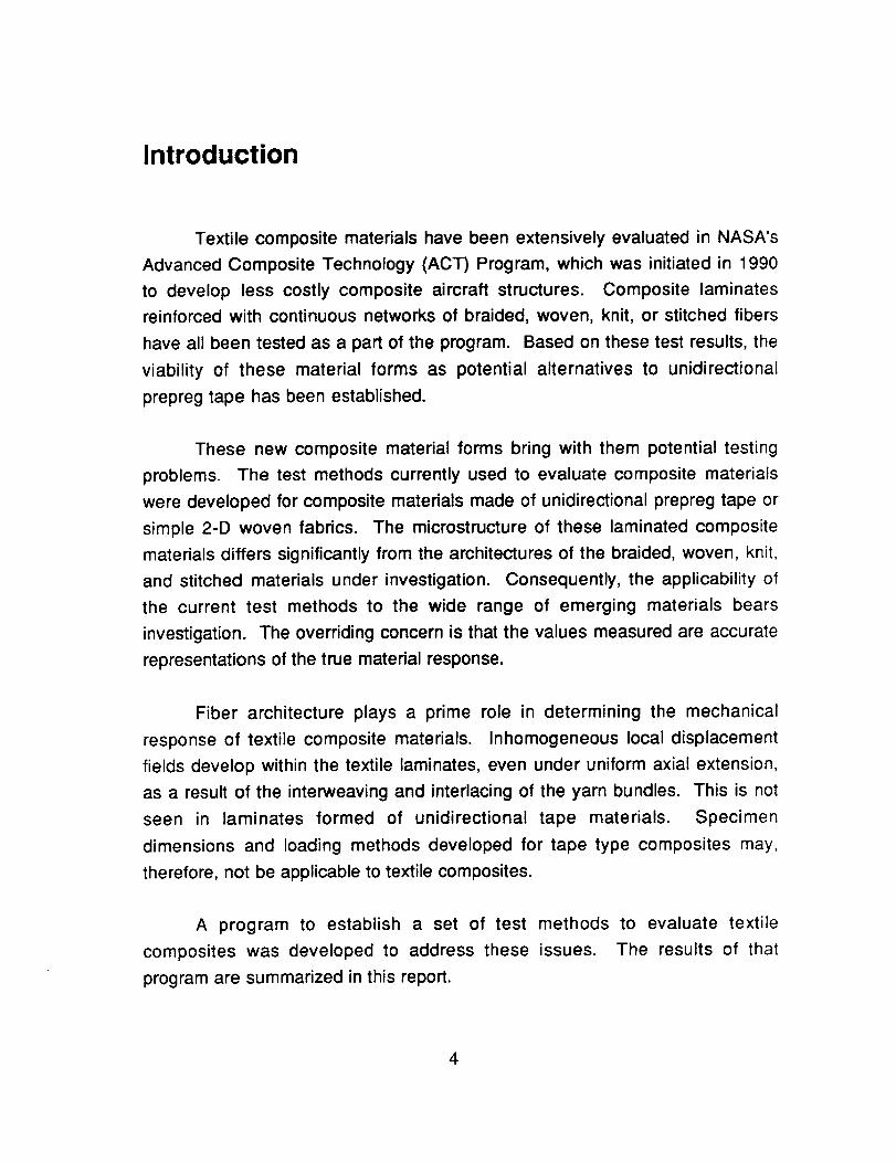
Abstract
Standard testing methods for composite laminates reinforced with
continuous networks of braided, woven, or stitched fibers have been evaluated.
The microstructure of these "textile" composite materials differs significantly from
that of tape laminates. Consequently, specimen dimensions and loading
methods developed for tape type composites may not be applicable to textile
composites. To this end, a series of evaluations were made to assess the
applicability of testing practices currently used in the composite industry to
textile composite materials.
Information was gathered from a variety of sources and analyzed to
establish a series of recommended test methods. The current practices
established for laminated composite materials by ASTM and the MIL-HDBK-17
Committee were considered. This document provides recommended test
methods for determining both in-plane and out-of-plane properties.
Specifically, test methods are suggested for:
• Unnotched Tension and Compression
• Open and Filled Hole Tension
• Open Hole Compression
• Bolt Bearing
• Interlaminar Tension
A detailed description of the material architectures evaluated is also
provided, as is a recommended instrumentation practice.
3
Introduction
Textile composite materials have been extensively evaluated in NASA's
Advanced Composite Technology (ACT) Program, which was initiated in 1990
to develop less costly composite aircraft structures. Composite laminates
reinforced with continuous networks of braided, woven, knit, or stitched fibers
have all been tested as a part of the program. Based on these test results, the
viability of these material forms as potential alternatives to unidirectional
prepreg tape has been established.
These new composite material forms bring with them potential testing
problems. The test methods currently used to evaluate composite materials
were developed for composite materials made of unidirectional prepreg tape or
simple 2-D woven fabrics. The microstructure of these laminated composite
materials differs significantly from the architectures of the braided, woven, knit,
and stitched materials under investigation. Consequently, the applicability of
the current test methods to the wide range of emerging materials bears
investigation. The overriding concern is that the values measured are accurate
representations of the true material response.
Fiber architecture plays a prime role in determining the mechanical
response of textile composite materials. Inhomogeneous local displacement
fields develop within the textile laminates, even under uniform axial extension,
as a result of the interweaving and interlacing of the yarn bundles. This is not
seen in laminates formed of unidirectional tape materials. Specimen
dimensions and loading methods developed for tape type composites may,
therefore, not be applicable to textile composites.
A program to establish a set of test methods
composites was developed to address these issues.
program are summarized in this report.
to evaluate textile
The results of that
4

Introduction
Information was gathered from a variety of sources and analyzed to
establish the recommended test methods. The current practices established by
ASTM and the MIL-HDBK-17 Committee for laminated composite materials
were considered. Test data developed by the Boeing Defense and Space
Group under contract to NASA was the primary source of information on test
method development for textile composite materials. In addition, Lockheed
Aeronautical Systems Company conducted an extensive materials evaluation
program on braided and woven textile systems. The test practices and data
developed in that program were also evaluated.
This report has been preceded by a series of contractor reports that
extensively review the data and detail the analysis that led to the establishment
of the individual test methods and practices. They are referenced in the
following sections. The reader should seek additional details in these
documents.
The following section provides a detailed description of the materials
investigated. It is followed by a recommended instrumentation practice for
textile composites and a series of recommended test methods.
5

Description of Materials
The primary contributor of test data to this report was the Boeing Defense
and Space Group in Philadelphia, PA. Supplemental data, obtained from
Lockheed Aeronautical Systems in Marietta, GA and West Virginia University
(WVU) in Morgantown, WV, was also reviewed. Most of the data was derived
from tests on two-dimensional triaxial braids and three-dimensional interlocking
weaves. Test results obtained for three-dimensional braided materials by
Lockheed and for stitched uniweaves by Boeing were also considered.
All 2-D and 3-D fabric preforms were constructed using Hercules AS4
fibers. They were manufactured by outside sources and then resin transfer
molded (RTM) at Boeing or Lockheed facilities. The resin systems employed
were formulated to have properties similar to Hercules 3501-6. They are low-
cost brittle epoxy systems with low viscosity at melt temperature that lend
themselves to the resin transfer molding process. The specifics of each material
system are described in the following sections.
2-Dimensional Triaxial Braids
In a triaxially braided preform three yarns are intertwined to form a single
layer of 0°/+ O° material. Each + O yarn crosses alternatively over and under
two - e yarns and vice verse. The 0 ° yarns were inserted between the braided
yarns. This yields a two-dimensional material; there is no through-the-thickness
reinforcement. Figure 1 schematically illustrates the fiber architecture and
establishes the nomenclature used in the paper.
Fiber Innovations Inc., of Norwood, MA, braided all the 2-D fabric
preforms investigated. Boeing and WVU evaluated identical 2-D braided
architectures; Lockheed's braids were slightly different. The Boeing and WVU
material was RTM'd using Shell RSL-1895 epoxy resin and cured at Boeing.
Details of their manufacturing process can be obtained in Ref. [1]. Lockheed's
6

Description of Materials
2-D material was RTM'd using
Lockheed's facility in Marietta, GA.
PR-500 epoxy resin and was cured at
Braider
yams
Resintransfer
Axialloading
direction
Transverse
Axial -_---Ioadingyams direction
Braidangle
Figure 1. Illustration of a Typical 2-D Triaxial Braid.
A shorthand notation, similar to the practice used to define the stacking
sequence of laminates formed of unidirectional prepreg tape, has been
developed to define the braid architecture. The proposed notation is
[0° xk / ---0 ° yk] N% Axial
where: e indicates the braid angle,
x indicates the number of fibers in the axial yarn bundles,
y indicates the number of fibers in the braided yarn bundles,
k indicates thousands, and
N indicates the percentage by volume of axial yarns in the preform
?

Description of Materials
Boeing and WVU tested four 2-D triaxial braid architectures; Lockheed
evaluated two. The specifics of each are given in Tables 1 and 2.
Table 1. Description of Boeing's 2-D Braided Architectures.
Braid Code Axial
Yarn
Size
[030K/+706K]46% 30 k
[036K/+4515K]46% 36 k
[075K/+_7015K]46% 75 k
[06K/+4515K]12% 6 k
[015K/+703K]46% 15 k
[030K/+4512K]47% 30 k
[015K/+456K]47% 15 k
Braided
Yarn
Size
6k
AxialYarn
Content
(%)
46
Braid
Angle
(°)
_+70
Unit Cell
Width
(inch)
0.458
0.415
Unit Cell
Length
(inch)
0.083
0.20715 k 46 +45
15 k 46 +70 0.829 0.151
15 k 12 +45 0.415 0.207
3 k 46 +70 0.349 0.063
12 k 47 +45 0.349 0.175
6 k 47 +45 0.262 0.131
Table 2. Description of Lockheed's 2-D Braided Architectures.
Braid Code
[012K/-+606K]33%
[024K/-+606K]50%
Axial Yarn
Size
12 k
24k
Braided Yarn
Size
6k
6k
Axial Yarn
Content
(%)
33.3
5O
Braid Angle(o)
+60
+60
3-Dimensional Braids and Weaves
Although the largest portion of the data were gathered for 2-D braided
materials, Boeing and Lockheed also evaluated a variety of materials reinforced
with three-dimensional fibrous preforms. Boeing tested 3-D woven materials;
Lockheed evaluated both 3-D woven and 3-D braided systems.

Description of Materials
Three types of 3-D interlocking weave configurations were investigated:
through-the-thickness orthogonal interlock, through-the-thickness angle
interlock, and a layer-to-layer interlock. They all provide true through-the-
thickness reinforcement by interlacing yarns in the z direction. These three
configurations are shown schematically in Figure 2. The specifics of each of the
3-D weave constructions investigated are given in Tables 3 and 4.
Orthogonal Interlock
Figure 2.
Angle Interlock Layer-to-Layer Interlock
Schematics of the Three 3-D Interlock Weave Types Investigated.
Boeing evaluated six 3-D woven architectures. They are described in
detail in Table 3. The preforms were produced by Textiles Technologies Inc.
and, like the 2-D braids, molded and cured at Boeing using Shell RSL-1895
epoxy. As the table indicates, two yarn sizes were investigated for each of the
three weave patterns studied.
9

Description of Materials
Table 3. Description of Boeing's 3-D Interlock Woven Architectures,
Description
Through-the-Thickness
Orthogonal Interlock
Through-the-Thickness
Angle Interlock
Layer-to-Layer
Interlock
WarpYarn
Weft Yarn Weaver
Yarn
Macro Cell
(inch)
Unit Cell
(inch)
24 k (59%) 12 k (33%) 6 k (7.4%) a
12 k (58%) 6 k (37%) 3 k (6.1%) 0.130 x 0.140 0.065 x 0.070
24 k (57%) 12 k (33%) 6 k (9.8%) 0.895 x 0.435 0.445 x 0.085
12 k (56%) 6 k (38%) 3 k (5.8%) 0.905 x 0.490 0.455 x 0.070
24 k (58%) 12 k (34%) 6 k (6.8%) 0.375 x 0.355 0.185 x 0.070
12 k(57%) 6 k (36%) 3 k (5.9%) 0.355 x 0.565 0.180 x 0.080
Lockheed evaluated two interlocking weave constructions. They are
described in Table 4. Their preforms were also produced by Textiles
Technologies Inc. They were RTM'd at Lockheed using PR-500 epoxy.
Although Lockheed's preforms were similar in design to Boeing's, they were
constructed with different size tows and contained a different percentage of
axial yarns. Thus, a direct comparison can not be made with Boeing's results.
Table 4. Description of Lockheed's 3-D Woven Architectures.
LTL-1
LTL-2
Description
Through-the-Thickness
Angle Interlock
Layer-to-Layer
Interlock
Warp Yarn
12 k (47.7%)
6 k (45.7%)
12 k (46.3%)
Weft Yarn
6 k (44.4%)
6 k (46.1%)
6 k (45.6%)
Weaver Yarn
3 k (7.9%)
3 k (8.2%)
3 k (8.1%)
Lockheed also produced and tested three 3-D braid configurations. The
specifics of each are described in Table 5. These 3-D fabrics were braided by
Atlantic Research Corp. and then RTM'd at Lockheed using PR-500 epoxy
resin.
10

Description of Materials
Table 5. Lockheed's 3-D Braided Architectures.
Name
1Tr-1
Braid Angle
+60
Axial Tow
6 K (30.3%)
i
Bias Tow
6 K (69.7%)
TTT-2 + 60 18K (56.3%) 6 K (43.7%)
1TI'-3 +60 6 K (38.9%) 6 K (61.1%)
Stitched Uniweaves
Stitched uniweaves were also evaluated by Boeing. The uniweave
fabric was produced by Textile Technologies Inc., stitched by Cooper
Composites, and then RTM'd at Boeing. All the materials tested featured a 48
ply quasi-isotropic, [+45/0/-45/9016s, layup. The stitching media and density
were varied to provide a measure of their effect on performance. The specifics
of each preform are described below in Table 6. An illustration of a typical
stitched uniweave is shown in Figure 3.
Figure 3.
0 ° Direction
Stitch 4
Spacingk_ff41-/ ,L
/ iii ili', iii iii ii! ii! ',iil__ 9oo• /_ilili_!ii_iii_i!_i_i__i_ -Direction
-
ii !i!iiiii !i!iii!i !i,Illustration of the Stitched Uniweave Construction.
11

Description of Materials
Table 6.
Name
Description of Boeing's Stitched Uniweave Architectures.
Stitch Material Pitch Spacing
(Stitches /inch)
8
Kevlar 29i
Stitch Spacing(inch)
Stitch Yarn
Size
SU-1 $2 Glass 0.125 3 k
SU-2 $2 Glass 8 0.125 6 k
SU-3 Kevlar 29 8 0.125 6 k
SU-4 Kevlar 29 4 0.250 6 k
SU-5 8 0.125 12 k
The Unit Cell
A textile composite's preform architecture presents a variety of size
effects that are not encountered in tape laminates. A convenient way to analyze
a textile composite is to consider a unit cell of the material. A unit cell is defined
as a unit of repeated fiber architecture. It may be considered the building block
of the material. The size of the unit cell is dependent on a number of factors
including the size of the yarns, the angle at which they are intertwined or
interwoven, and the intricacy of the braid or weave pattern.
Figure 4 shows a repeated unit of the braid architecture that is sometimes
referred to as the braid's natural unit cell. It represents the complete yarn or tow
intertwinement pattern. It is desirable, for analysis purposes, to define the
smallest unit cell possible. Rectangular unit cells are also preferable. The box
outlined within the rhombic natural unit cell defines the smallest unit cell for the
triaxial braids tested in this investigation [Ref. 2].
In a 2-D triaxial braid, the unit cell width is dependent on mandrel
diameter and the number of yarns braided. The height of the unit cell is
dependent on the cell width and the braid angle. In this document, the unit cell
width of a 2-D braid is defined as twice the spacing of the axial tows. Axial tow
spacing can be calculated by multiplying the braider mandrel diameter by _,
]2

Description of Materials
then dividing the result by the number of axial carrier yarns. The unit cell length
is calculated by multiplying the cotangent of the braid angle by half the unit cell
width. The sizes of the minimum unit cells for the braids tested at Boeing are
summarized in Table 1.
SmallestUnit Cell
TUnit CellHeight
I _ Unit Cell ,= IWidth "_ I
Figure 4. Definition of the Unit Cell in a 2-D Triaxial Braid.
Repeated units of fabric geometry, or unit cells, have also been defined
for the 3-D woven materials. Chou et. al. [Ref. 3], for example, have defined
macro unit cells for these woven laminates that are analogous to the natural unit
cell defined for 2-D braids. The depth of these macro unit cells is equal to the
laminate thickness. Their length is defined by the length of the periodic
interlocking yarns. Figure 5a, for example, illustrates the cross section of a TS-1
through-the-thickness interlock laminate. In this case, the length of the macro
unit cell is defined by the wavelength, a, of the yarn as it completes one cycle
through the laminate thickness.
13

Description of Materials
I a I
Fig. 5a. Cross Section No. 1. Fig. 5b. Cross Section No. 2.
000 000 - O0
Fig. 5c. Cross Section No. 3. Fig. 5d. Cross Section No. 4.
Fig. 5e. Cross Section No. 5.
Figure 5. Cross-Sections of Woven Laminate TS1.
In practice, the patterns of the yarns woven through the laminate's
thickness, as shown in Figure 5a, are staggered across the width of the
material. To demonstrate, Figure 5 illustrates five adjacent cross-sections of a
TS-1 laminate. As the figure illustrates, the relative positions of the through-the-
thickness yarns vary at each cross-section. The yarns would return to the
positions shown in Figure 5a if a sixth cross section were illustrated. The widths
of the macro cells were defined by the number of units required to complete this
cycle. Schematic cross sections of the six interlocking weaves investigated in
this study are illustrated in Ref. 4. The wavelengths of the yarns woven through
14

Description of Materials
the laminates' thicknesses are illustrated in the figures. The relative positions of
these yarns in the adjacent laminate cross sections are also illustrated.
Table 3 lists the dimensions of the macro unit cells for the woven
materials investigated at Boeing. The values listed in the table were
experimentally determined through direct measurements of sectioned laminates
[Ref. 3].
As in the case of the 2-D triaxial braids, smaller unit cells may also be
defined within the macro cells of the woven laminates. For the woven laminates
investigated in this study, they are defined as one half the interlocking yarn's
wavelength, a/2. Their widths are determined by dividing the macro cell's width
by the number of sections required to complete the cycle, i.e., five for the TS-1
and LS-1 laminates, seven for the TS-2 and LS-2 laminates, and four or two for
the OS-1 and OS-2 laminates, respectively. The dimensions of these smaller,
building block unit cells are also listed in Table 3 for each weave architecture.
References
°
=
.
=
Falcone, A., Dursch, H., Nelson, K., Avery, W., "Resin Transfer Molding of
Textile Composites," NASA Contractor Report 191505, March 1993.
Masters, J. E., et. al., "Mechanical Properties Of Triaxially Braided
Composites: Experimental And Analytical Results," Journal of Composites
Technology and Research, JCTRER, Vol. 15, No. 2, Summer 1993.
Hardranft, D., Parvizi-Majidi, A., and Chou, T.-W., "Testing and
Characterization of Through-the-thickness Properties of Multi-Directionally
Reinforced Textile Composites," Quarterly Progress Report, NASA
Advanced Composites Technology: Mechanics of Textile Composites
Work Group, March 1994, pp. 219 - 249.
Masters, J. E., Strain Gage Selection Criteria for Textile Composite
Materials, NASA Contractor Report 198286, Feb. 1996.
t5

Standard Guide for the Instrumentation of TextileComposites
Introduction:
Inhomogeneous local
displacement fields develop within
textile composite materials even
under uniaxial loading conditions as
a result of the interweaving and
interlacing of the yarn bundles. For
example, significant variations in the
applied normal strain, ¢y, have been
measured in 2-D braided laminates
subjected to uniform axial extension
[Ref. 2.1.1]. In this instance the local
normal strains within the material's
unit cell varied by a factor of 2. The
variations were located on the
surface over the fiber bundles;
normal strain was nearly constant
throughout all of the resin rich zones
between yarns. Inhomogeneous
displacement fields of this type are
not typically seen in laminates
formed of unidirectional tape
materials.
The preceding example
illustrates the significance of the
variations in displacement field
homogeneity that have been
identified in textile composite
specimens. Test specimens must,
therefore, be designed to
encompass representative volumes
of material within their test sections
to obtain characteristic measures of
mechanical response. The size and
type of instrumentation used plays a
similarly critical role in obtaining
accurate measurements.
There are, of course, two
common methods of instrumenting
test specimens: strain gages and
extensometers. Extensometers
provide a more global measure of
material response and will cost less
in the long run since they are
reusable. They have been applied
effectively to textile composite
materials.
Extensometers are not,
however, applicable to all test
situations. For example, although
suitable for coupon testing,
extensometers cannot be easily
mounted to large test panels. Once
mounted, extensometers can also
limit specimen handling. In most
]6

Instrumentation Guide for Textile Composites
cases this would disturb the
continuity of their measurements.
Strain gages are more versatile;
they can be applied to a wider
variety of test situations. They are
permanently affixed to the specimen
and, therefore, permit its removal
from the test machine for inspection,
etc. Strain gages do, however,
provide only a local measure of the
material response and are,
therefore, subject to local
inhomogeneity. In particular, the
inhomogeneity of the local
displacement fields that develop in
textile composites present a special
challenge to strain gage usage.
An experimental investigation
[Ref. 2.1.2] was conducted to
establish performance levels for
strain gages on textile composites
and to determine the sensitivity of
strain measurements to the size of
the strain gage. The results of that
study were analyzed to establish a
set of recommendations for the use
of strain gages
composites.
recommendations are
in this guide.
on textile
These
summarized
1. Scope.
1.1 This guide defines
recommended procedures for
instrumenting textile composite
materials to measure the strains that
develop in these materials under
mechanical and thermal loading.
This guide does not attempt to
address all the aspects of
instrumentation. Rather, criteria that
establish the minimum strain gage
size required to yield reproducible
measurements are presented. This
method is limited to the textile
architectures identified in Section
5.4.
2. Reference Documents.
2.1 Reference Publications:
2.1.1 Naik, R. A., Ifju, P. G., and
Masters, J. E., "Effect of Fiber
Architecture Parameters on
Deformation Fields and Elastic
Moduli of 2-D Braided Composites,"
Journal of Composite Materials, Vol.
28, No. 7/1994, pp. 656 - 681.
2.1.2 Masters, John E., "Strain
Gag e Selection Criteria for
Textile Composite Materials,"
NASA CR 198286, Feb. 1996.
l?

Instrumentation Guide for Textile Composites
2.1.3 Pastore, Christopher M.,
"Illustrated Glossary of Textile Terms
for Composites", NASA CR 191539,
Sept. 1993.
2.2 ASTM Standards:
D883 Terminology Relating to
Plastics.
D3878 Terminology of High-
Modulus Reinforced Fiber and Their
Composites.
E6 Terminology Relating to
Methods of Mechanical Testing.
E83-94 Practice for Verification
and Classification of Extensometers.
E251-92 Standard Test
Methods for Performance
Characteristics of Metallic Bonded
Resistance Strain Gages.
E456 Terminology Relating to
Quality and Statistics.
E1237-93 Guide for Installing
Bonded Resistance Strain Gages.
E1434 Guide for Development
of Standard Data Records for
Computerization of Mechanical Test
Data for High-Modulus Fiber-
Reinforced Composite Materials.
OIML International
Recommendation No. 62:
"Performance Characteristics of
Metallic Resistance Strain Gages."
3. Terminology.
3.1 Definitions m Definitions
used in this guide are defined by
various ASTM methods. ASTM
method D3878 defines terms
relating to high-modulus fiber and
their composites. ASTM method
D883 defines terms relating to
plastics. ASTM method E6 defines
terms relating to mechanical testing.
ASTM method E456 defines terms
relating to statistics. In the event of a
conflict between definitions of terms,
ASTM method D3878 shall have
precedence over the other
standards.
3.2 Description of Terms Specific
to This Guide:
3.2.1 Bonded Resistance Strain
Gage-- a resistive element with a
carrier that is attached by bonding to
]8

Instrumentation Guide for Textile Composites
the base material so that the
resistance of the element will vary
as the surface of the base material
to which it is attached is deformed.
(For a complete definition of this
term see ASTM Test Methods E
251.)
3.2.2 Throughout this guide the
terms "strain gage" and "gage" are
to be understood to represent the
longer, but more accurate, "metallic
bonded resistance strain gages."
3.2.3 Terms relating
specifically to textile composites are
defined by Reference 2.1.3;
3.2.4 The Unit Cell _ In theory,
textile composites have a repeating
geometrical pattern based on
manufacturing parameters. This
repeating pattern is often called the
material's "unit cell". It is defined as
the smallest section of architecture
required to repeat the textile pattern.
Handling and processing can distort
the "theoretical" unit cell. Although
some parameters, such as tow size
and fiber angle, may be explicitly
defined, calculation of unit cell
dimensions tend to be somewhat
subjective. Unit cell dimensions are
based on varying interpretations of
the textile architecture. Refer to
Chapter 2 of this document for a
description of the method used to
determine 2-D braided and 3-D
woven material unit cell dimensions.
4. Summary of Guide.
4.1 Bonded resistance strain
gages and extensometers are used
to measure material deformation
that results when mechanical or
thermal loads are applied to a
material. The optimum and
reproducible application of these
sensors is dependent upon a variety
of factors including: proper gage
selection, surface preparation, gage
installation, lead wire connection,
and verification checks.
4.1.1 Several guides and
methods have been developed to
define the factors listed above.
Strain gage installation guidelines
have been established in E1237-93.
Test methods that define the
performance characteristics of strain
gages and extensometers are given
in E251-92 and E83-94,
respectively.
]9

Instrumentation Guide for Textile Composites
4.1.2 The surface preparation,
gage installation, lead wire
connection, and verification check
procedures and practices defined in
the above referenced documents
are applicable to textile composites.
This guide will address strain gage
selection for textile composites.
5. Significance and Use.
5.1 The intent of this guide is to
define strain gage size selection
criteria for textile composites.
5.2 Textile composites have a
less homogeneous nature than
composites constructed from pre-
preg tape. Consequently, greater
care must be taken in gage
selection to adequately characterize
these materials. Each textile
architecture has an independent
unit cell size. This repeating
inhomogeneity may cause variability
in the test results if strain gages are
sized solely by using guidelines
established for tape materials.
5.2.1 As a general rule, gage size
should normally be small with
respect to the dimensions of an
immediately adjacent geometric
irregularity (hole, fillet, etc.) to
minimize errors due to strain
gradients over the gage area.
However, the gage size should
generally be large relative to the
underlying material structure (grain
size, fabric-reinforced composite
weave or braid pattern).
5.3 This test method is the result
of studies conducted by Lockheed
Engineering and Science under
contract to NASA Langley Research
Center. Data was derived from tests
on two dimensional triaxial braids,
three dimensional interlocking
weaves, and stitched uniweaves.
An evaluation of the test results is
available in reference document
2.1.2, Strain Gage Practice for
Textile Composites, NASA CR
198286, Feb. 1996.
5.4 This guide is recommended
for experiments conducted on 2-D
braids, 3-D weaves, and stitched
uniweave architectures evaluated in
reference document 2.1.2. and
described in Chapter 3 of this report.
Specifically, the gage size selection
criteria have only been evaluated
using the textile composites
described in Chapter 2 of this
document.
2O

Instrumentation Guide for Textile Composites
5.4.1 The 2-D braided materials'
unit cells ranged from 0.415 inch to
0.829 inch in width and from 0.083
inch to 0.207 inch in height. The
widths of the 3-D woven materials'
unit cells ranged from 0.070 inch to
0.085 inch ; their heights ranged
from 0.065 inch to 0.455 inch. All
the stitched materials evaluated
featured a stitch pitch of 8 stitches
per inch; the rows of stitches were
1/8 inch apart.
6.0 Gage Selection.
kept at 2. Data were not gathered
for other gage configurations.
6.2 3-D Woven Laminates.
6.2.1 Test results obtained for
specimens loaded in the warp
direction (longitudinal direction)
indicate that reproducible results
were obtained when gage length
equaled the unit cell length in the
load direction. This is a minimum.
Both braided and woven laminate
test results indicted that the scatter
in the data is greatly decreased as
the gage length increases.
6.1 2-D Tnaxial Braids.
6.1.1 The experimental results
indicate that gage length should, at
a minimum, equal the length of the
unit cell in the load direction. This
applies to specimens loaded in the
axial fiber direction (longitudinal
direction) and to specimens loaded
perpendicular to the axial fibers
(transverse direction). No
relationship between gage width
and scatter in the data was
discerned. Thus, a rectangular
gage is sufficient. If rectangular
gages are used, it is recommended
that the gage length to width ratio be
6.2.2 A more restrictive gage
selection criteria is required for
specimens loaded in the fill direction
(transverse direction). Test results
obtained for these specimens
indicated that the gage length must
exceed unit cell length by a factor of
four. The application of this criterion
is mitigated since the unit cells, as
defined in Chapter 2, are quite
narrow. The criterion could be met
with relatively standard and
affordable 0.375 inch gages, for
example, in the laminates evaluated
in this report.
2]

Instrumentation Guide for Textile Composites
6.3 Stitched Laminates.
6.3.1 The results of the
evaluation of the stitched laminates
indicted that strain gage size did not
influence the modulus measurement
or the scatter in the data.
Acceptable results were obtained
using 0.125 inch gages even though
their lengths and widths were equal
to the stitch spacing and pitch. This
should be considered a minimum
gage size for this stitch
configuration, however, until data
are developed for smaller gages.
22
Standard Test Method for Unnotched TensionTesting of Textile Composites
1. Scope
1.1 This test method is a
recommended procedure fordetermining the unnotched tensionstrength of textile compositematerials. This recommendationdoes not attempt to address allaspects of unnotched tension testingof all textile architectures. Rather,procedures are recommended toestablish a standard method ofunnotched tension testing betweentesting laboratories. This method islimited to the textile architectures
identified in Chapter 2 of thisdocument.
1.2 This test method does not
purport to address all of the safetyissues associated with its use. It is
the responsibility of the user toestablish appropriate safety andhealth practices prior to initiatingtesting.
2.1.3 Pastore, Christopher M.,"Illustrated Glossary of Textile Termsfor Composites", NASA CR 191539,Sept. 1993.
2.1.4 Masters, John E., "StrainGage Practice for TextileComposites", NASA CR 198286,Feb. 1996.
2.2 ASTM Standards:
D792 Test Methods for SpecificGravity and Density of Plastics byDisplacements.
D883 Terminology Relating toPlastics.
D2584IgnitionResins.
Test Method forLoss of Cured Reinforced
D2734 Test Methods for VoidContent of Reinforced Plastics.
2. Reference DocumentsD3039 Test Method for
Tensile Properties of Polymer MatrixComposite Materials.
2.1 Reference Publications:
2.1.1 Minguet, Pierre J., Fedro,Mark J., Gunther, Christian K., "restMethods for Textile Composites"NASA CR 4609, July 1994.
2.1.2 Portanova, M.A., "StandardMethods for Unnotched Tension
Testing of Textile Composites",NASA CR 198264, Dec. 1995.
D3171 Test Method for FiberContent of Resin Matrix Compositesby Matrix Digestion.
D3878 Terminology of High-Modulus Reinforced Fiber and Their
Composites.
E6 Terminology Relating toMethods of Mechanical Testing.
23

Unnotched Tension Testing of Textile Composites
E177 Practice for use of TermsPrecision and Bias in ASTM TestMethods.
E456 Terminology Relating toQuality and Statistics.
E1434 Guide for Developmentof Standard Data Records forComputerization of Mechanical TestData for High-Modulus Fiber-Reinforced Composite Materials.
3. Terminology
3.1 Definitions _ Definitionsused in this test method are definedby various ASTM methods. ASTMmethod D3878 defines terms
relating to high-modulus fiber andtheir composites. ASTM methodD883 defines terms relating toplastics. ASTM method E6 definesterms relating to mechanical testing.ASTM methods E456 and E177
define terms relating to statistics. Inthe event of a conflict betweendefinitions of terms, ASTM methodD3878 shall have precedence overthe other standards.
3.2 Description of Terms Specificto This Standard _ Terms relatingspecifically to textile composites aredefined by reference publication2.1.3; Pastore, Christopher M.,"Illustrated Glossary of Textile Termsfor Composites", NASA CR 191539,Sept. 1993.
3.3 The Unit Cell _ In theory,textile composites have a repeatinggeometrical pattern based onmanufacturing perameters. Thisrepeating pattern is often called thematerial's "unit cell". It is defined asthe smallest section of architecture
required to repeat the textile pattern.Handling and processing can distortthe "theoretical" unit cell. Althoughsome parameters, such as tow sizeand fiber angle, may be explicitlydefined, calculation of unit celldimensions tend to be somewhat
subjective. Unit cell dimensions arebased on varying interpretations ofthe textile architecture. For a
description of the method used todetermine the unit cell dimensionsrefer to Chapter 2 of this document.
4. Summary of Test Method
4,1 Uniaxial tension tests of a
textile composite materials areperformed in accordance with ASTMStandard Test Method D3039. The
unnotched specimen shown inFigure 1 is mounted in the grips ofthe testing machine. Load cell andstrain gage output must be recordedif modulus properties are desired.Otherwise, just load cell output isrequired.
24

Unnotched Tension Testing of Textile Composites
f Tab
Tab Length_ _ Ga§_ Le%,h
i:i: :i:i: 8_: _':_:":_-':'.:_":"
:!ii:!iii_::Ei_:_. :'_
Figure 1. Unnotched Tension Test Specimen
5. Significance and Use
5.1 Textile composites have aless homogeneous nature thancomposites constructed from pre-preg tape. Consequently, standardcomposite testing methods may notbe adequate to characterize thesematerials. Each textile architecture
has an independent unit cell size.This repeating inhomogeneity maycause variability in the test results ifspecimens are sized solely by usingguidelines established for tapematerials.
5.2 This test method is designedto produce unnotched tensionproperty data for materialspecifications, research anddevelopment and design. Thefactors that influence tensile
properties, and, therefore, should bereported are: textile architecture asdescribed by section 3.2, themethod of material and specimenpreparation, conditioning, fibervolume fraction and void content,the environment of testing andspeed of testing. Properties, in the
test direction, that may be obtainedfrom this test method include:
5.2.1 Ultimate tensile
strength,
5.2.2 Ultimate tensile strain,
5.2.3 Tensile modulus ofelasticity,
5.2.4 Poison's ratio in tension,and
5.2.5 Transition strain.
5.3 This test method is the resultof studies conducted at threeindependent testing laboratories.The primary contributor of test datawas Boeing Defense and SpaceGroup in Philadelphia, PA.Supplemental data, obtained fromLockheed Aeronautical Systems inMarietta, GA and West VirginiaUniversity (WVU), was alsoexamined. Most of the data wasderived from tests on two
25
Unnotched Tension Testing of Textile Composites
dimensional triaxial braids and threedimensional interlocking weaves.Some results for stitched uniweaveswere also evaluated. An evaluationof the test method was made usingresults from each of the namedcontributors and is available inreference document 2.1.2,Portanova, M.A., "Standard Methodsfor Unnotched Tension Testing ofTextile Composites", NASA CR198264, Dec. 1995.
5.4 This method is recommendedfor experiments conducted on 2-Dbraids, 3-D weaves, and similartextile architectures evaluated inreference document 2.1.2.Specifically, this test method hasonly been evaluated using thebraids and weaves described in
Chapter 2 of this document.
5.5 This test method has onlybeen evaluated under room
temperature - dry test conditions. Itsapplicability to testing textile
6.1 The test apparatus used shallbe in accordance with ASTM TestMethod D3039.
6.2 Additionally, required strainmeasurements shall be made usingan extensometer or strain gages ofsufficient size as compared to thetextiles unit cell size. Unit cellcalculations shall be madeaccording to Section 3.3 of thismethod. Strain gage selection shallbe made in accordance with
reference publication 2.1.4 of thistest method, Masters, John E.,"Strain Gage Size Effects of TextileComposites", NASA CR 198286,Feb. 1996
7. Sampling & Test Specimens
7.1 Sampling m Test at least fivespecimens per series unless validresults can be obtained using lessspecimens, such as by using adesigned experiment. Forstatistically significant data use the
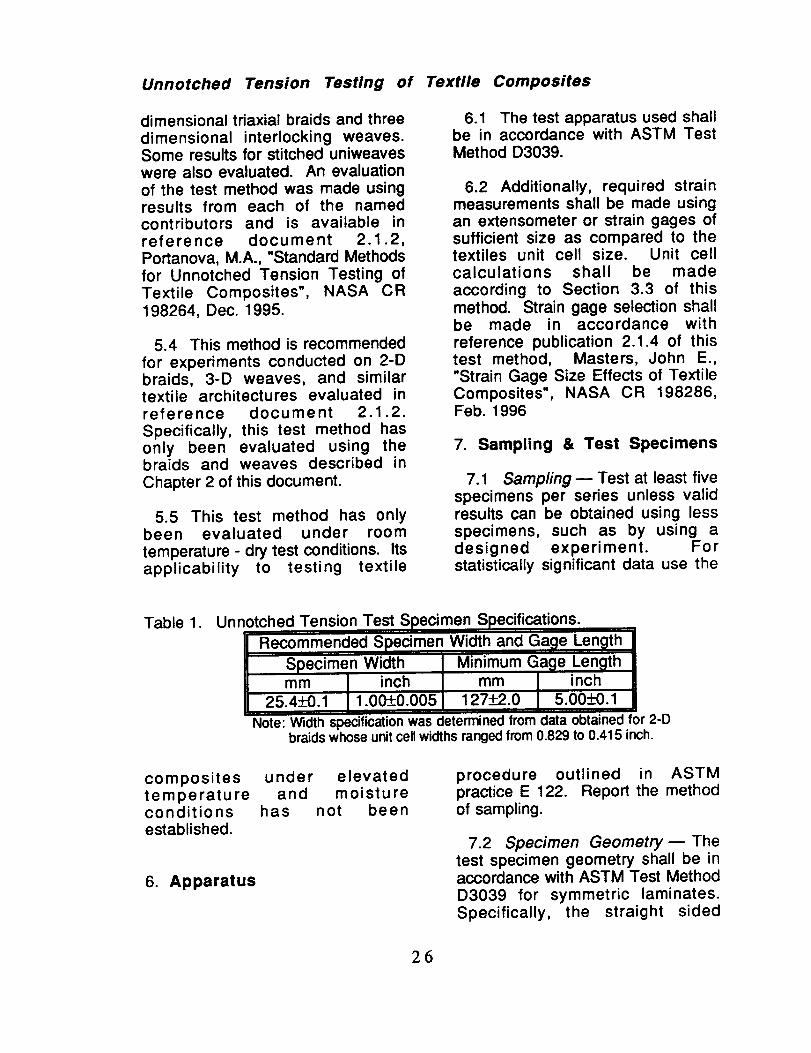
Table 1. Unnotched Tension Test Specimen Specifications.
I Recommended Specimen Width and Gage Length !1Specimen Width I Minimum Gage Length
| mm I inch I mm I inch _II 2s.4_+0.111.0 0.00 1127 .0 s.oo_+0.1IINote: Width specificationwas determinedfromdata obtainedfor 2-D
braidswhoseunitcellwidthsrangedfrom0.829 to 0.415 inch.
composites under elevatedtemperature and moistureconditions has not beenestablished.
6. Apparatus
procedure outlined in ASTMpractice E 122. Report the methodof sampling.
7.2 Specimen Geometry- Thetest specimen geometry shall be inaccordance with ASTM Test MethodD3039 for symmetric laminates.Specifically, the straight sided
26

Unnotched Tension Testing of Textile Composites
specimen geometry illustrated inFigure 1 shall be as described inTable 1. The test specimen shallhave a constant rectangular crosssection with a specimen widthvariation of no more than + 1% anda specimen thickness variation of nomore than + 4%.
7.2.1 Ratio of Specimen Widthto Unit Cell Size B Therecommended specimen width wasdetermined through the evaluationof 2-D braided materials whose unit
cells ranged from 0.415 inch to0.829 inch in width. The evaluation
of textile composites whose unitcells are wider may require testspecimens of greater width.
7.3 Specimen Fabrication _ Thespecimens may be moldedindividually without cut edges ormachined from a plate after bondingon tab material. If cut from a plate,precautions must be take to avoidnotched, undercuts, or rough edges.When machined, each specimenshould be saw cut oversized and
ground to the final dimensions.
7.4 Tabbing m Tabs should bestrain compatible with the compositebeing tested. The most consistentlyused bonded tab material has been
continuous E-glass fiber-reinforcedpolymer matrix materials (woven ofunwoven) in a [0/90]ns laminateconfiguration. The tab material iscommonly applied at 45 ° to theloading direction to provide a softinterface.
Equation 1 can be used toestimate the minimum suggestedtab length for bonded tabs. As this
equation does not account for thepeaking stresses that are known toexist at the ends of bonded joints,the tab length calculated by thisequation should normally beincreased by some factor to reducethe chances of joint failure.
L,= O'ch 1.2_"
where
Lmin =
h =
(_C "
tab lengthspecimen thickness,
estimated strength ofthe composite
shear strength of theadhesive, specimen, ortab (whichever islowest).
The tabs used in Ref 2.1.1, whichcomprised the bulk of the dataevaluated to establish this method,were 2.25 inches long. Theyfeatured a 5 ° taper.
8. Conditioning
8.1 Standard ConditioningProcedure _ Unless a different
environment is required, the testspecimens shall be conditioned inaccordance with ASTM Procedure Cof Test Method D5229 / D5229M..
Store and test at standard laboratoryconditions of 23+1° C [73.4+1.8 ° F]and 50+10 % relative humidity.
9. Procedure
9.1 General Instructions:
27
Unnotched Tension Testing of Textile Composites
9.1.1 Report any deviations fromthis test method, whether intentionalor inadvertent.
9.1.2 Following final specimenmachining and any conditioning, butbefore the tension testing, determinethe area as A = w x h at three placesin the gage section and report thearea as the average of these threedeterminations, to an accuracy of __.0.0001 in. in thicknessmeasurements and +_0.001 in. inwidth measurements. Record theminimum values of cross-sectionalarea so determined.
9.2 Speed of Testing m Testingspeed shall set at a constantdisplacement rate of between 0.02and 0.05 in/min as required toproduce failure within 1 to 10 rain.
9.3 Specimen Insertion _ Placethe specimen in the grips of thetesting machine, taking care to alignthe long axis of the grippedspecimen with the test direction.Tighten the grips, recording thepressure used on pressurecontrollable (hydraulic orpneumatic) grips.
9.4 Transducer Installation _ Ifstrain response is to be determinedattach the strain-indicationtransducer(s) to the specimen,symmetrically about the mid-span,mid-width location. Attach the strain
recording instrumentation to thetransducers on the specimen.
9.5 Loading _ Apply the load tothe specimen at the specified rateuntil failure, while recording data.
9.6 Data Recording
9.6.1 Record load versus strain (ortransducer displacement)continuously, or at frequent regularintervals. If a transition region(marked by a change in the slope ofthe stress-strain curve) is noted,record the load, strain, and mode ofdamage at such points. If thespecimen is to be failed, record themaximum load, the failure load, thestrain (or transducer displacement)at, or as near as possible to, themoment of rupture.
9.6.2 Other valuable data that canbe used in understanding testinganomalies and gripping orspecimen slipping problems includeload versus head displacement andload versus time data. These data
may also be recorded.
9.6.3 When determining themodulus of elasticity it isrecommended that at least one
specimen per series be tested withback-to-back axial transducers to
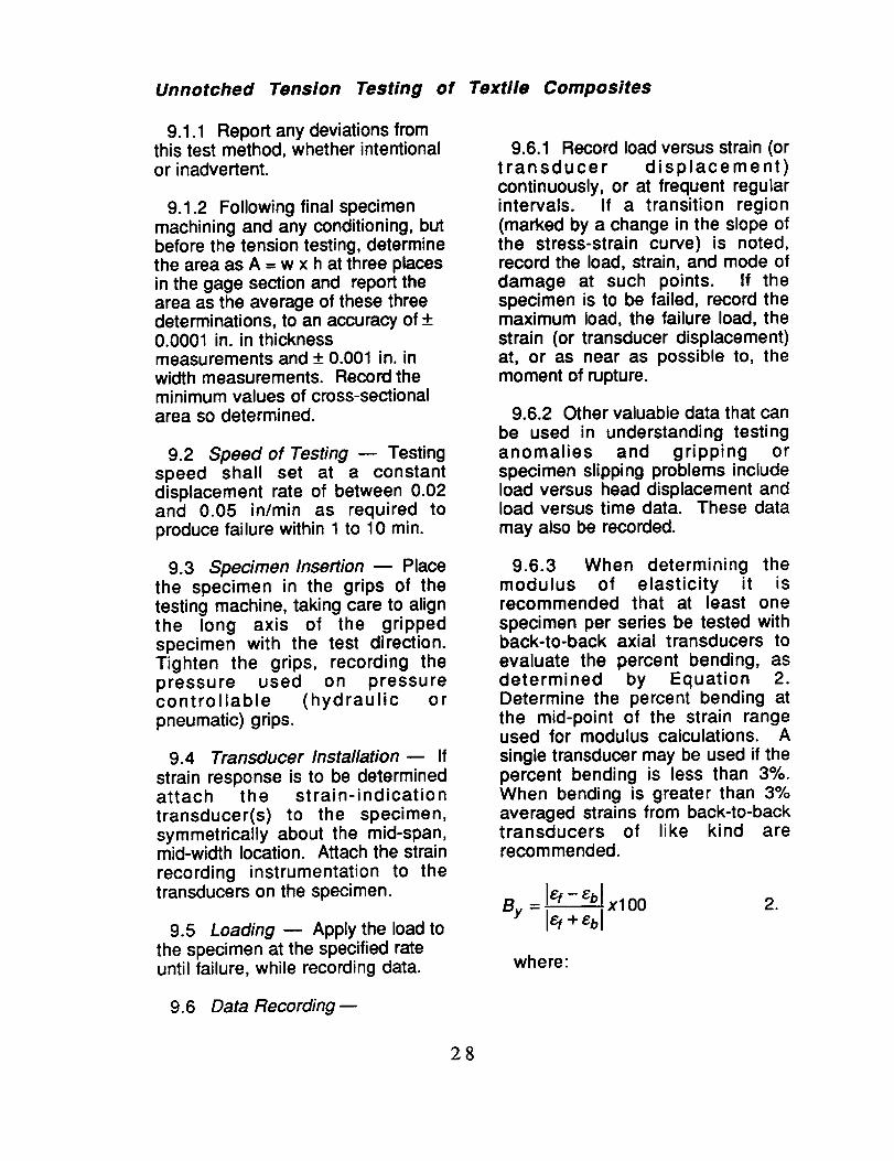
evaluate the percent bending, asdetermined by Equation 2.Determine the percent bending atthe mid-point of the strain rangeused for modulus calculations. A
single transducer may be used if thepercent bending is less than 3%.When bending is greater than 3%averaged strains from back-to-backtransducers of like kind arerecom mended.
.
where:
28

Unnotched Tension Testing of Textile Composites
By = percent bending in
specimen.
_f = indicated strain from
front transducer, IJ.¢.
z_b = indicated strain from
back transducer, !_.
9.7 Failure Mode m Record themode and location of failure of the
specimen.
9.8 Grip/Tab Failures _ Re-examine the means of loadintroduction into the material if a
significant fraction of the failures in asample population occur within onespecimen width of the tab or grip.Factors considered should include
the tab alignment, tab material, tabangle, tab adhesive, grip type, grippressure, and grip alignment.
10. Calculations
Calculations shall be made usingthe following equations:
10.1 Tensile StrengthCalculate tensile strength using thefollowing equation. Report results tothree significant digits.
where
Gu_
P
PO'u. = m
wt.
= ultimate tensile
strength, MPa or Ksi.= maximum load, N or Ibf.
W
t
= minimum specimenwidth, mm or in.
= minimum specimenthickness, mm or in.
10.2 Elastic ModulusCalculate the modulus of elasticityusing equation 4. Longitudinalstrain shall be determined byevaluating the linear range between
1000 and 3000 I_E. Report results tothree significant digits.
E= -_- _- =-_- 4.
where:
E = modulus of elasticity,MPa or Ksi.
AP/AI = slope of the linear regionof the load---deformationcurve.
I = gage length of strainmeasuring instrument,mm or in.
w = minimum specimenwidth.
t = minimum specimenthickness.
10.2.1 Tabulated strains should
only be determined for materialsthat do not exhibit a significantchange in the slope of the stress-strain curve. If a transition regionoccurs within the recommended
strain range, then a more suitablestrain range shall be used andreported.
29
Unnotched Tension Testing of Textile Composites
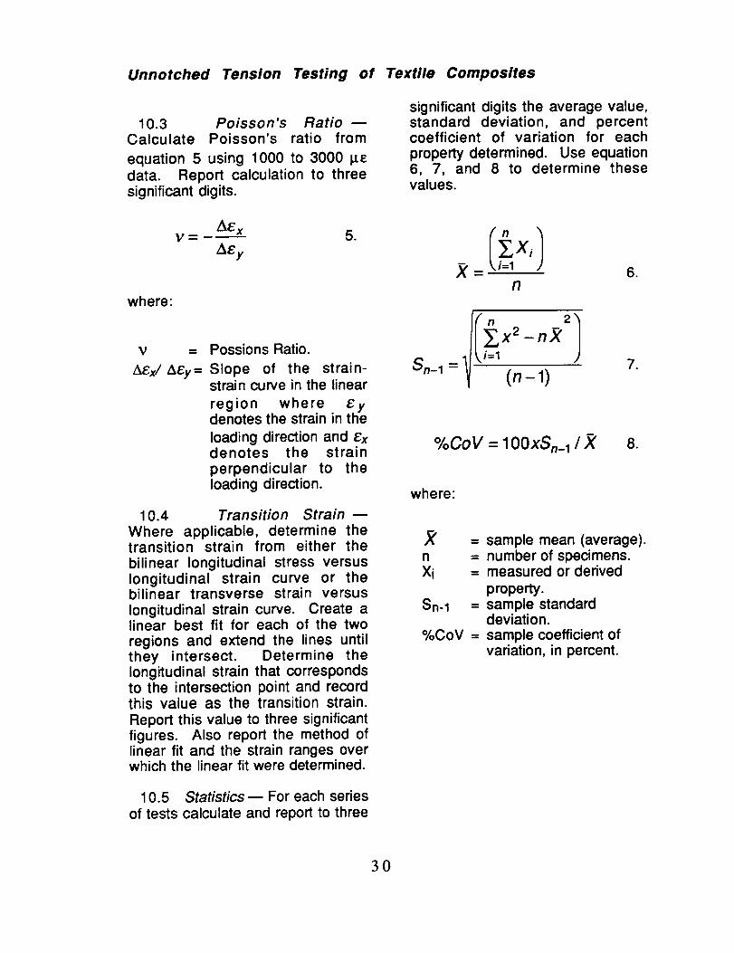
10.3 Poisson's RatioCalculate Poisson's ratio from
equation 5 using 1000 to 3000 l_edata. Report calculation to threesignificant digits.
AE xV=-_ 5.
AEy
where:
Possions Ratio.
Slope of the strain-strain curve in the linear
region where eydenotes the strain in the
loading direction and exdenotes the strain
perpendicular to theloading direction.
10.4 Transition Strain
Where applicable, determine thetransition strain from either the
bilinear longitudinal stress versuslongitudinal strain curve or thebilinear transverse strain versuslongitudinal strain curve. Create alinear best fit for each of the two
regions and extend the lines untilthey intersect. Determine thelongitudinal strain that correspondsto the intersection point and recordthis value as the transition strain.Report this value to three significantfigures. Also report the method oflinear fit and the strain ranges overwhich the linear fit were determined.
10.5 Statistics m For each series
of tests calculate and report to three
significant digits the average value,standard deviation, and percentcoefficient of variation for each
property determined. Use equation6, 7, and 8 to determine thesevalues.
n.
-n)(
Sn-1 = C1).
%CoY = lOOXSn_ 1 / )( 8.
where:
X = sample mean (average).n = number of specimens.Xi = measured or derived
property.Sn-1 = sample standard
deviation.%CoV = sample coefficient of
variation, in percent.
3O

Unnotched Tension Testing of Textile Composites
11. Report 12. Precision and Bias
11.1 The report shall include allappropriate parameters inaccordance with ASTM Test MethodD3039, making use of ASTM guidesE1309, E1471, and E1434.
11.2 As a minimum, the reportshall include the following:
11.2.1 A complete identificationof the material tested using termsdefined in reference publication2.1.3; Pastore, Christopher M.,"Illustrated Glossary of Textile Termsfor Composites", NASA CR 191539,Sept. 1993.
11.2.2 The number of specimenstested.
11.2.3 The fiber and resin densityused and how they were measured.
11.2.4 The average value andstandard deviation of the fiber
volume fraction of the compositeand how it was measured.
11.2.5 The average value ofultimate strength and it's coefficientof variation.
12.1 The following criteria shouldbe used for judging the acceptabilityof the results:
12.1.1 Repeatability n Theresults should be considered
suspect if two averages obtained bythe same testing laboratory differ bymore than 2 standard deviations.
12.1.2 Reproducibility _ Theresults should be considered
suspect if two averages obtained bydifferent testing laboratories differ bymore than 2.8 standard deviations.
31

Standard Test Method for UnnotchedCompression Testing of Textile Composites
1. Scope
1.1 This test method determinesthe unnotched compression strengthof textile composite materials. Thisrecommendation does not attempt toaddress all aspects of unnotchedcompression testing of all textilearchitectures. Rather, proceduresare recommended to establish astandard method of unnotchedcompression testing between testinglaboratories. This method is limitedto the textile architectures identifiedin Section 5.4.
1.2 This test method does not
purport to address all of the safetyissues associated with its use. It is
the responsibility of the user toestablish appropriate safety andhealth practices prior to initiatingtesting.
for Composites", NASA CR 191539,Sept. 1993.
2.1.4 Masters, John E., "StrainGage Practice for TextileComposites', NASA CR 198286,Feb. 1996.
2.2 ASTM Standards:
D792 Test Methods for SpecificGravity and Density of Plastics byDisplacements.
D883 Terminology Relating toPlastics.
D2584 Test Method forIgnition Loss of Cured ReinforcedResins.
D2734 Test Methods for VoidContent of Reinforced Plastics.
2. Reference Documents.
2.1 Reference Publications:
D3410-94 CompressionProperties of Polymer MatrixComposite Materials withUnsupported Gage Sections byShear Loading.
2.1.1 Minguet, Pierre J., Fedro,Mark J., Gunther, Christian K., "TestMethods for Textile Composites"NASA CR 4609, July 1994.
2.1.2 Masters, John E.,"Compression Testing of TextileComposites", NASA CR 198285,Feb. 1996.
2.1.3 Pastore, Christopher M.,"Illustrated Glossary of Textile Terms
D3171 Test Method for FiberContent of Resin Matrix Compositesby Matrix Digestion.
D3878 Terminology of High-Modulus Reinforced Fiber and TheirComposites.
E6 Terminology Relating toMethods of Mechanical Testing.
32

Unnotched Compression Testing of Textile Composites
E177 Practice for use of TermsPrecision and Bias in ASTM TestMethods.
E456 Terminology Relating toQuality and Statistics.
E1434 Guide for Developmentof Standard Data Records for
Computerization of Mechanical TestData for High-Modulus Fiber-Reinforced Composite Materials.
3. Terminology.
3.1 Definitions m Definitionsused in this test method are definedby various ASTM methods. ASTMmethod D3878 defines terms
relating to high-modulus fiber andtheir composites. ASTM methodD883 defines terms relating toplastics. ASTM method E6 definesterms relating to mechanical testing.ASTM methods E456 and E177
define terms relating to statistics. Inthe event of a conflict betweendefinitions of terms, ASTM methodD3878 shall have precedence overthe other standards.
3.2 Description of Terms Specificto This Standard: _ Terms relatingspecifically to textile composites are
defined by reference publication2.1.3; Pastore, Christopher M.,"Illustrated Glossary of Textile Termsfor Composites", NASA CR 191539,Sept. 1993.
3.3 The Unit Cell _ In theory,textile composites have a repeatinggeometrical pattern based onmanufacturing parameters. Thisrepeating pattern is often called thematerial's "unit cell". It is defined asthe smallest section of architecturerequired to repeat the textile pattern.Handling and processing can distortthe "theoretical" unit cell. Althoughsome parameters, such as tow sizeand fiber angle, may be explicitlydefined, calculation of unit celldimensions tend to be somewhatsubjective. Unit cell dimensions arebased on varying interpretations ofthe textile architecture. Refer toChapter 2 of this document for adescription of the method used todetermine 2-D braided and 3-Dwoven material unit cell dimensions.
4. Summary of Test Method.
4.1 A flat strip of material havinga constant rectangular cross-section, as shown in Figure 1, isloaded in compression by a shear
_:!:!:!:_:!:!:!:i:!:!:!:!:!:!:!:!:!:!:!:i:i:i:i:i:i:i:!:i:!:i:!:i:i:i:i:i:i:i:!:i:i:i:i:i:i:i:i::i::!:!:!:!:!:i:!:!:!:!:!:i:!:i:!:!:i:!_!:!:i:i:i:i:i:i:i:i:i:i:i:i::i_i:i:!:i::i:i::i:i:i:i:i:i:i:i:i::i:i:i:::i:!:i:!:!:!:!:!:i:i:!:!:!:::i::::::::::::::::::::::::::::::::::::::::::::::i:!:i:i:|
Strain Gage at Centerline
i l iiiiiiiiiiiiiiiiiiiiiii!!ii!iiiiiiiiiii iiiii iiiiiiiiiiiii!iiiiiii!iilFigure 1 Compression Test Specimen.
.50 in, W
33

Unnotched Compression Testing of Textile Composites
load acting along the grips. Theshear load is applied via wedgegrips.
4.2 To obtain compression testresults, the specimen is inserted intothe test fixture [Ref. 2.1.2] shown inFigure 2. The test fixture provideslateral support along the specimenlength to prevent bucking. Theuntabbed specimen ends are thenmounted in the testing machinegrips. The specimen is then loadedin axial compression. The ultimatecompression strength of thematerial, can be determined fromthe maximum load carried prior to
5. Significance and Use.
5.1 Textile composites have aless homogeneous nature thancomposites constructed from pre-preg tape. Consequently, standardcomposite testing methods may notbe adequate to characterize thesematerials. Each textile architecture
has an independent unit cell size.This repeating inhomogeneity maycause variability in the test results ifspecimens are sized solely by usingguidelines established for tapematerials.
.07"
____ 3.0_O ____O O
.....c ;;T-._ 0 0 0 ,,
7.50 --_
Figure 2. Unnotched Compression Test Fixture.
failure. Strain is monitored with
strain or displacement transducersso the stress-strain response of thematerial can be determined. Theultimate compressive strain, thecompression modulus of elasticity,Poisson's ratio in compression, andthe transition strain can bedetermined from the stress-straincurve.
5.2 This test method is designedto produce unnotched compressionproperty data for materialspecifications, research anddevelopment and design. Thefactors that influence compressionproperties and, therefore, should bereported are: textile architecture asdescribed by section 3.2, themethod of material and specimen
preparation, conditioning, fibervolume fraction and void content,the environment of testing and
speed of testing. Properties, in thetest direction, that may be obtainedfrom this test method include:
34

Unnotched Compression Testing of Textile Composites
5.2.1strength,
Ultimate compressive
5.2.2 Ultimate compressive strain,
5.2.3 Compressive modulus ofelasticity,
5.2.4 Poison'scompression, and
ratio in
5.2.5 Transition strain.
5.3 This test method is the resultof studies conducted at two
independent testing laboratories.The primary contributor of test datawas the Boeing Defense and SpaceGroup in Philadelphia, PA.Supplemental data, obtained fromLockheed Aeronautical Systems inMarietta, GA, was also examined.Most of the data was derived fromtests on two dimensional triaxialbraids and three dimensionalinterlocking weaves. Some resultsfor stitched uniweaves were alsoevaluated. An evaluation of the test
method was made using resultsfrom each of the named contributorsand is available in referencedocument 2.1.2 Masters, John E.,"Compression Testing of TextileComposites", NASA CR 198285,Feb. 1995.
5.4 This method is recommended
for experiments conducted on 2-Dbraids, 3-D weaves, and similartextile architectures evaluated inreference document 2.1.2.Specifically, this test method hasonly been evaluated using thebraids and weaves described in
Chapter 2 of this document.
5.4.1 The recommended testspecimen geometry was determinedthrough the evaluation of 2-Dbraided materials whose unit cells
ranged from 0.415 inch to 0.829inch in width. The evaluation of
textile composites with wider unitcells may require test specimens ofgreater width.
5.4.2 The recommended testspecimen geometry was determinedthrough the evaluation of 0.125 inchthick 2-D braided materials whose
moduli ranged from 4.9 to 10.6 MSI.Data establishing the viability of thetest specimen geometry to textilecomposites with lower moduli and tothinner specimens are not available.
5.4.3 This test method has onlybeen evaluated under roomtemperature - dry test conditions. Itsapplicability to testing textilecomposites under elevatedtemperature and moistureconditions has not beenestablished.
6. Apparatus
6.1 The test fixture shown in Fig.1 (Ref. 2.1.1) shall be used tosupport the test specimen. All otherapparatus used shall be inaccordance with ASTM Test MethodD3410-94.
6.2 Strain-Indicating Device :
6.2.1 Longitudinal strain shall besimultaneously measured onopposite faces of the specimen toallow for a correction due to anybending of the specimen, and toenable detection of Euler (column)
35

Unnotched Compression Testing of Textile Composites
buckling. Back-to-back strainmeasurement shall be made for all
five specimens when the minimumnumber of specimens allowed bythis test method are tested. If morethan five specimens are to be testedthen a single strain-indicatingdevice may be used for theadditional specimens, provided allspecimens are tested in a single testfixture that remains in the load frame
throughout the tests, that nomodifications to the specimens orthe test procedure are made duringthe tests, and provided the bendingrequirements of Section 9.4.3 aremet for the first five specimens. Ifthese conditions are not met, thenall specimens must be instrumentedwith back-to-back gages.
6.2.2 When the Poisson's ratio isto be determined, the specimen
an extensometer or strain gages ofsufficient size as compared to thetextiles unit cell size. Unit cellcalculations shall be made
according to Section 3.3 of thismethod. Strain gage selection shallbe made in accordance withreference publication 2.1.4 of thistest method, Masters; John E.,"Strain Gage Size Effects of TextileComposites', NASA CR 198286,Feb. 1996
7. Sampling & Test Specimens
7.1 Sampling m Test at least fivespecimens per series unless validresults can be obtained using lessspecimens, such as by using adesigned experiment. Forstatistically significant data use theprocedure outlines in ASTM practice
Table 1. Unnotched Compression Test Specimen Specifications.
Recommended Specimen DimensionsWidth Len_lth Thickness
38.0-Z_0.15 mm 305.0__3.0 mm
(1.50_+0.005 in.) (12._.1 in.)
3.18_+0.125 mm
10.125!-0.005 in.)
Note: W"_lthspecification was determined from data obtained for 2-D braids whoseunit cell widths ranged from 0.829 to 0.415 inch.
shall be instrumented to measurestrain in the lateral direction usingthe same type of transducer. Thesame type of strain transducer shallbe used for all strain measurements
on any single coupon. Attachmentof the strain-indicating device to thecoupon shall not cause damage tothe specimen surface.
6.3 Additionally, required strainmeasurements shall be made using
E 122. Report the method ofsampling.
7.2 Specimen Geometry- Thestraight sided test specimengeometry, illustrated in Figure 1,shall be in accordance with thedimensions listed in Table 1. The
test specimen shall have a constantrectangular cross section with aspecimen width variation of no morethan _+ 1% and a specimen
36
Unnotched Compression Testing of Textile Composites
thickness variation of no more than+ 4%.
7.2.1 The recommended
specimen width was determinedthrough the evaluation of 2-Dbraided materials whose unit cells
ranged from 0.415 inch to 0.829inch in width. The evaluation of
textile composites whose unit cellsare wider may require testspecimens of greater width.
7.2.2 The recommended
specimen thickness was determinedthrough the evaluation of 0.125 inchthick 2-D braided materials whose
moduli ranged from 4.9 to 10.6 MSl.The application of this method tothinner textile laminates or tomaterial with a lower modulus maylead to Euler (column) buckling inthe unsupported section of the testspecimen. See Section 9.4.4.
7.3 Specimen Fabrication m Thespecimens may be moldedindividually without cut edges ormachined from a plate. If cut from aplate, precautions must be take toavoid notched, undercuts, or roughedges. When machined, eachspecimen should be saw cutoversized and ground to the finaldimensions.
8. Conditioning
8.1 Standard ConditioningProcedure _ Unless a different
environment is required, the testspecimens shall be conditioned inaccordance with ASTM Procedure Cof Test Method D5229 / D5229M..Store and test at standard laboratory
conditions of 23+1° C [73.4+1.8 ° F]and 50!-_10 % relative humidity.
9. Procedure
9.1 General Instructions:
9.1.1 Report any deviation fromthis test method, whether intentionalor inadvertent.
9.1.2 If specific gravity, density,reinforcement volume, or voidvolume are to be reported, thenobtain these samples from the samepanels as the test samples. Specificgravity and density may beevaluated by means of Test MethodD792. Volume percent of theconstituents may be evaluated byone of the matrix digestionprocedures of Test Methods D3171,or, for certain reinforcementmaterials, such as glass, by thematrix burn-off technique of TestMethod D2584. Void content maybe evaluated from the equations ofTest Method D2734, and areapplicable to both Test MethodsD2584 and D3171.
9.1.3 Following final specimenmachining and any conditioning, butbefore the compression testing,measure the specimen area as A =W x t at three placed in the gagesection and report the area as theaverage of these threemeasurements to within 1%
accuracy. Record the average areain units of in2.
9.1.4 Apply strain gages to bothfaces of the specimen as shown inFig. 1.
37

Unnotched Compression Testing of Textile Composites
9.2 Speed of Testing _ Set thespeed of testing to effect a nearlyconstant strain rate in the gagesection. Testing speed shall set at aconstant displacement rate ofbetween 0.02 and 0.05 in/min asrequired to produce failure within 1to 10 min.
9.3 Fixture Installation andSpecimen Insertion:
9.3.1 Check the alignment of theloading frame to ensure that thegrips are in good condition and thatthey will load the specimen properly.
9.3.2 Check all load and straingage recording instruments toinsure that they are functioningproperly.
9.3.3 Place the specimen in theCompression Test Fixture. The twohalves of the support fixture shouldbe only lightly bolted together toprovide contact support to thespecimen Load the specimen andthe fixture into the grips, taking careto maintain proper alignment of thelong axis of the specimen with theloading direction..
9.4 Data Recording:
9.4.1 Record load versus strain (ordisplacement) continuously, or atfrequent regular intervals. If atransition region (marked by achange in the slope of the stress-strain curve) is noted, record theload, strain, and mode of damage atsuch points. If the specimen is to befailed, record the maximum load, thefailure load, and the strain at, or asnear as possible to, the moment offailure.
9.4.2 Other valuable data that canbe used in understanding testinganomalies and gripping orspecimen slipping problems includeload versus head displacement andload versus time data. These data
may also be recorded.
9.4.3 A difference in the stress-strain or load-strain slope fromopposite faces of the specimenindicates bending in the specimen.In order for the elastic property testresults to be considered valid,percent bending in the specimenshall be less than 10% as
determined by Equation 1.Determine the percent bending atthe mid-point of the strain rangeused for modulus calculations. The
same requirements shall be met atfailure strain for strength and strain-to-failure data to be consideredvalid. This requirement shall be metfor all five of the specimen requiringback-to-back strain measurements.
If possible, a plot of the percentbending versus average strainshould be recorded to aid in thedetermination of the failure mode.
where:
By
Ef
£b
= percent bending in
specimen.= indicated strain from
front transducer, I_.
= indicated strain from
back transducer, I_E.
.
38

Unnotched Compression Testing of Textile Composites
9.4.4 Rapid divergence of thestrain readings of the opposite facesof the specimen, or rapid increase inpercent bending, is indicative of theonset of Euler (column) buckling,which is not an acceptablecompression failure mode for thistest method. Record any indicationof Euler buckling.
9.4.5 If the divergence is clearlydue to the failure of only one of thestrain gages and not the result ofbending or twisting on thespecimen, the results of the oneworking strain gage may be usedand recorded as the longitudinalstrain. The data report shouldclearly indicate this circumstance.
10. Calculations
10.1 Calculations of the elastic
properties shall be made wheneverpossible using the followingequations:
10.1.1 Compression StrengthCalculate the ultimate compressionstrength using Eqn. 2 and reportresults to three significant digits.
t = minimum specimenthickness, mm or in.
10.1.2 Compressive Modulus ofElasticity _ Calculate the modulusof elasticity from the stress-straindata using Equation 3. Data
gathered over the 1000 to 3000 I_Estrain range shall be used in thesecalculations. If data are notavailable at the exact strain rangeend points, use the closest availabledata point. Report the modulus ofelasticity to three significant figures.Also report the strain range used inthe calculation.
10.1.2.1 The recommended strain
ranges should only be used formaterial that do not exhibit a
transition region (a significantchange in the slope of the stress-strain curve) within therecommended strain range. If atransition region occurs within therecommended strain range, then amore suitable strain range shouldbe used and reported.
E= -_-.T _- =_-s 3.
where:
PGu_ Wt
.
where
O'u_t = ultimate compressionstrength, MPa or KSI.
P = maximum load, N or Ibf.w = minimum specimen
width, mm or in.
E
&P/ AI =
I =
w =
modulus of elasticity,MPa or KSI.
slope of the linear regionof the load--deformationcurve.gage length of strainmeasuring instrument,mm or in.
minimum specimenwidth.
39

Unnotched Compression Testing of Textile Composites
t = minimum specimenthickness.
10.1.3 Poisson's Ratio mDetermine the transverse strain
(strain in the plane of the specimenand perpendicular to the applied
load), Ex, at each point over thelongitudinal strain range of 1000 to
3000 I_. If data are not available atthe exact strain range end points,use the closest available data point.Calculate Poisson's ratio from
Equation 4. Report the results of thecalculation to three significant digits.
A£ xV-- 4.
AEy
where:
Poisson's Ratio.
Slope of the strain-strain curve in the linear
region where eydenotes the strain in the
loading direction and exdenotes the strain
perpendicular to theloading direction.
10.1.3.1 When determining thePoisson's ratio, match thetransverse strain with the
appropriate longitudinal strain. Forinstance, match the output from asingle transverse strain gage withthe output from the singlelongitudinal gage mounted in anadjacent location on the same sideof the coupon. If back-to-backtransverse gages are employed,
average their output and compare tothe average longitudinal strain.
10.1.4 Transition Strain
Where applicable, determine thetransition strain from either thebilinear longitudinal stress versuslongitudinal strain curve or thebilinear transverse strain versuslongitudinal strain curve. Create alinear best fit for each of the two
regions and extend the lines untilthey intersect. Determine thelongitudinal strain that correspondsto the intersection point and recordthis value as the transition strain.
Report this value to three significantfigures. Also report the method oflinear fit and the strain ranges overwhich the linear fit were determined.
10.1.5 Statistics _ For eachseries of tests calculate and report tothree significant digits the averagevalue, standard deviation, andpercent coefficient of variation foreach property determined. Useequation 5, 6, and 7 to determinethese values.
Xj
X=n
.
n 2/Sn_ 1 = "_1_'i=1 __ ___
(n-l).
%CoV = 100XSn_ 1 / )( 7.
4O

Unnotched Compression Testing of Textile Composites
where:
,X" = sample mean (average).n = number of specimens.Xi = measured or derived
property.Sn-1 = sample standard
deviation.
%CoV = sample coefficient ofvariation, in percent.
1 1. Report
11.1 The report shall include allappropriate parameters inaccordance with ASTM Test MethodD3410-94, making use of ASTMguides E1309, E1471, and E1434.
11.2 As a minimum, the reportshall include the following:
11.2.1 A complete identificationof the material tested using termsdefined in reference publication2.1.3; Pastore, Christopher M.,"Illustrated Glossary of Textile Termsfor Composites", NASA CR 191539,Sept. 1993.
11.2.2 The number of specimenstested.
11.2.3 The fiber and resin
densities used and how they weremeasured.
11.2.4 The average value andstandard deviation of the fibervolume fraction of the compositeand how it was measured.
11.2.5 The average values of theultimate compressive strength,compressive modulus of elasticity,and their coefficients of variation.
11.3 Where applicable, thefollowing may also be reported:
11.3.1 Ultimatestrain,
compressive
11.3.2 Compressive modulus ofelasticity,
11.3.3 Poison's ratio incompression, and
11.3.4 Transition strain.
12. Precision and Bias
12.1 The following criteria shouldbe used for judging the acceptabilityof the results:
12.1.1 Repeatability m Theresults should be considered
suspect if two averages obtained bythe same testing laboratory differ bymore than 2 standard deviations.
12.1.2 Reproducibility _ Theresults should be considered
suspect if two averages obtained bydifferent testing laboratories differ bymore than 2.8 standard deviations.
4]

Standard Test Method for Open Hole TensionTesting of Textile Composites
1. Scope
1.1 This test method determinesthe open hole tension strength oftextile composite materials. Thisrecommendation does not attempt toaddress all aspects of open holetension testing of all textilearchitectures. Rather, proceduresare recommended to establish astandard method of open holetension testing between testinglaboratories. This method is limitedto the textile architectures identifiedin Chapter 2 of this document.
1.2 This test method does not
purport to address all of the safetyissues associated with it's use. It isthe responsibility of the user toestablish appropriate safety andhealth practices prior to initiatingtesting.
2. Reference Documents
2.1 Reference Publications:
2.1.3 Pastore, Christopher M.,"Illustrated Glossary of Textile Termsfor Composites", NASA CR 191539,Sept. 1993.
2.1.4 Masters, John E.,
"Strain Gage Practice for TextileComposites", NASA CR 198286,Feb. 1996
2.2 ASTM Standards:
D792 Test Methods for SpecificGravity and Density of Plastics byDisplacements.
D883 Terminology Relating toPlastics.
D2584 Test Method for IgnitionLoss of Cured Reinforced Resins.
D2734 Test Methods for VoidContent of Reinforced Plastics.
D3039 Test Method for Tensile
Properties of Polymer MatrixComposite Materials.
2.1.1 Minguet, Pierre J., Fedro,Mark J., Gunther, Christian K., "TestMethods for Textile Composites"NASA CR 4609, July 1994.
2.1.2 Portanova, M.A., "StandardMethods for Open Hole TensionTesting of Textile Composites",NASA CR 198262, Dec. 1995.
D3171 Test Method for FiberContent of Resin Matrix Composites
by Matrix Digestion.
D3878 Terminology of High-Modulus Reinforced Fiber and TheirComposites.
D5766/D5766M - 95 StandardTest Method for Open Hole TensileStrength of Polymer MatrixComposite Laminates.
42

Open Hole Tension Testing of Textile Composites
E6 Terminology Relating toMethods of Mechanical Testing.
E177 Practice for use of TermsPrecision and Bias in ASTM TestMethods.
E456 Terminology Relating toQuality and Statistics.
E1434 Guide for Developmentof Standard Data Records forComputerization of Mechanical TestData for High-Modulus Fiber-Reinforced Composite Materials.
3. Terminology
3.1 Definitions n Definitionsused in this test method are definedby various ASTM methods. ASTMmethod D3878 defines termsrelating to high-modulus fiber andtheir composites. ASTM methodD883 defines terms relating toplastics. ASTM method E6 definesterms relating to mechanical testing.ASTM methods E456 and E177define terms relating to statistics. Inthe event of a conflict betweendefinitions of terms, ASTM methodD3878 shall have precedence overthe other standards.
3.2 Description of Terms Specificto This Standard _ Terms relatingspecifically to textile composites aredefined by reference publication2.1.3; Pastore, Christopher M.,"Illustrated Glossary of Textile Termsfor Composites", NASA CR 191539,Sept. 1993.
3.3 The Unit Cell m In theory,textile composites have a repeatinggeometrical pattern based onmanufacturing perameters. Thisrepeating pattern is often called thematerial's "unit cell". It is defined asthe smallest section of architecturerequired to repeat the textile pattern.Handling and processing can distortthe "theoretical" unit cell. Althoughsome parameters, such as tow sizeand fiber angle, may be explicitlydefined, calculation of unit celldimensions tend to be somewhatsubjective. Unit cell dimensions arebased on varying interpretations ofthe textile architecture. For adescription of the method used todetermine the unit cell dimension
refer to Chapter 2 of this document.
4. Summary of Test Method
4.1 Open Hole Tension Tests of atextile composite materials areperformed in accordance with ASTMStandard Test Method D5766. The
open hole tension specimen shownin Figure 1 is mounted in the grips ofthe testing machine and loaded inuniaxial tension to failure. Ultimatestrength is calculated based on thegross cross-sectional area,disregarding the hole, and thencorrected for finite width effects.
5. Significance and Use
5.1 Textile composites have aless homogeneous nature thancomposites constructed from pre-preg tape. Consequently, standardcomposite testing methods may notbe adequate to characterize these
43

Open Hole Tension Testing of Textile Composites
materials. Each textile architecturehas an independent unit cell size.This repeating inhomogeneity maycause variability in the test results ifspecimens are sized solely by usingguidelines established for tapematerials.
5.2 This test method is designedto produce notched tension strengthdata for material specifications,research and development, design,and quality assurance. The factorsthat influence tensile properties, andtherefore should be reported are:textile architecture as described bysection 3.2, the method of materialfabrication, specimen geometry(thickness, width, hole diameter),hole quality, specimen preparation,specimen fiber volume fraction andvoid content, the environment oftesting and speed of testing.Properties that may be derived fromthis test method include the
following:
5.2.1 Open hole (notched)tensilestrength.
Boeing, were also evaluated. Aevaluation of test method was made
using results from each of thecontributors and is available inreference document 2.1.2Portanova, M.A., "Standard Methodsfor Open Hole Tension Testing ofTextile Composites", NASA CR198262, Dec. 1995.
5.4 This method is recommendedfor experiments conducted on 2-Dbraids, 3-D weaves, and similartextile architectures evaluated inreference document 2.1.2.Specifically, this test method hasonly been evaluated using thebraids and weaves described inChapter 2 of this document.
5.5 This test method has onlybeen evaluated under roomtemperature - dry test conditions. Itsapplicability to testing textilecomposites under elevatedtemperature and moistureconditions has not beenestablished.
5.3 This test method is the resultof studies conducted at threeindependent testing laboratories.The primary contributor of test datawas Boeing Defense and SpaceGroup in Philadelphia, PA.Supplemental data, obtained fromLockheed Aeronautical Systems inMarietta, GA and West VirginiaUniversity (WVU), was alsoexamined. Most of the data wasderived from tests on twodimensional triaxial braids and threedimensional interlocking weaves.Lockheed also evaluated a threedimensional braid. Some results forstitched uniweaves, tested at
6. Apparatus
6.1 The test apparatus used shallbe in accordance with ASTM TestMethod D3039. However, the
procedure herein does not measurematerial response, so strain ordeflection measurement relateddiscussion in Test Method D3039 do
not apply. Additionally, amicrometer or gage capable ofdetermining the hole diameter to0.001 in. is required.
7. Sampling & Test Specimen
44

Open Hole Tension Testing of Textile Composites
7.1 Sampfing m Test at least fivespecimens per series unless validresults can be obtained using lessspecimens, such as by using adesigned experiment. Forstatistically significant data use theprocedure outlined in ASTMpractice E 122. Report the methodof sampling.
7.2 Specimen Geometry- Thetest specimen geometry shall be inaccordance with ASTM Test Method
D5766. Specifically, the straightsided specimen geometry illustratedin Figure 1 shall be as follows:
7.2.1 Specimen Width &Thickness -- A specimen width to
7.2.2 Recommenced Dimensions
D The specimen width shall be36+0.1 mm [1.50-Z_0.005 in.] and thelength range is 200 D 300 mm [8.0m 12.0 in.]. The centrally locatedhole shall be 6+0.06 mm
[0.250!-_0.003 in.] diameter and belocated within 0.13 mm [0.005 in.] ofthe axial centerline of the testspecimen.
7.2.3 Ratio of Specimen Widthto Unit Cell Size _ The
recommended specimen width wasdetermined through the evaluationof 2-D braided materials whose unitcells ranged from 0.415 inch to0.829 inch in width. The evaluation
-_ Length _J
"_Width
Open HoleEnd Tab 1/2 Width (w/D ratio = 6)
Figure 1. Open Hole Tension Test Specimen.
hole diameter ratio (W/d) of 6 mustbe maintained. A hole diameter to
thickness ratio (d/t) of 1.5 m 3.0 isrecommended. The test specimenshall have a constant rectangularcross section with a specimen widthvariation of no more than +_ 1% and
a specimen thickness variation of nomore than + 4%.
of textile composites whose unitcells are wider may require testspecimens of greater width.
7.3 Specimen Fabrication m Thespecimens may be moldedindividually without cut edges ormachined from a plate after bondingon tab material. If cut from a plate,precautions must be take to avoid
45

Open Hole Tension Testing of Textile Composites
notched, undercuts, or rough edges.When machined, each specimenshould be saw cut oversized and
ground to the final dimensions.
7.4 Hole Preparation _ Due tothe dominant presence of the notch,consistent preparation of the hole,without damage to the laminate, isimportant to meaningful results.Damage due to hole preparation willaffect strength results. Some typesof damage, such as delaminations,can blunt the stress concentration atthe hole and increase the load-
carrying capacity of the coupon.
7.5 End Tabs _ Tabs are not
required but may be used. Typicallythe hole induces a stress risersufficient to force failure in thenotched region.
8. Conditioning
8.1 Standard ConditioningProcedure D Unless a differentenvironment is required, the testspecimens shall be conditioned inaccordance with ASTM Procedure Cof Test Method D5229 / D5229M..
Store and test at standard laboratoryconditions of 23+1° C [73.4+1.8 ° F]and 50+10 % relative humidity.
9. Procedure
9.1 Genera/Instructions:9.1.1 Report any deviations from
this test method, whether intentionalor inadvertent.
9.1.2 Following final specimenmachining and any conditioning, butbefore the tension testing, determine
the area as A = w x h at three placesin the gage section and report thearea as the average of these threedeterminations, to an accuracy of _+0.0001 in. in thicknessmeasurements and + 0.001 in. inwidth measurements. Record theminimum values of cross-sectionalarea so determined. Also measureand report the spcimen holediameter to the nearest 0.001 in.
Inspect the hole and areas adjacentto the hole for delaminations.Report the location and size of anydelaminations found.
9.2 Speed of Testing m Testingspeed shall set at a constantdisplacement rate of between 0.02and 0.05 in/min, as required toproduce failure within 1 to 10 min.
9.3 Specimen Insertion _ Placethe specimen in the grips of thetesting machine, taking care to alignthe long axis of the grippedspecimen with the test direction.Tighten the grips, recording thepressure used on pressurecontrollable (hydraulic orpneumatic) grips.
9.4 Loading _ Apply the load tothe specimen at the specified rateuntil failure, while recording data.
9.5 Data Recording_
9.5.1 If possible, record loadcontinuously, or at frequent regularintervals. Record the maximum loadand the failure load at, or as near aspossible to, the moment of rupture.
9.5.2 Other valuable data that canbe used in understanding testinganomalies and gripping or
46

Open Hole Tension Testing of Textile Composites
specimen slipping problems includeload versus head displacement andload versus time data. These datamay also be recorded.
9.6 Failure Mode m Record themode and location of failure of the
specimen. The failure is oftenheavily influenced by delaminationand the failure mode may exhibitmuch delamination. Failures that donot occur at the hole are not
acceptable failure modes and thedata shall be noted as invalid.
10. Calculations
Calculations shall be made usingthe following equations:
10.1 Ultimate StrengthCalculate the ultimate open holetensile strength using Equation 1.Report results to three significantdigits.
mmaxGul t = _ 1.
wt
where:
O'u/t --
Pmax _
w =
t
ultimate open hole tensilestrength, MPa or Ksi.maximum load prior tofailure, N or Ibf.specimen width(neglecting the hole), mmorin.
specimen thickness, mmorin.
10.2 Data Correction _ The testdata shall be corrected for finitewidth using the following isotropic
finite width correction factor.
factor is defined by equation 2.
d 3[2 + (1-,7;) ]
wd
Ggross 3(1-_)
where
This
.
G=o = Infinite stress, MPa orKsi.
Ggross = Gross stress, MPa orKsi.
W = specimen width(neglecting the hole),rnm or in.
d = diameter of hole, mmor in.
10.3 Width to Diameter Ratio--Calculate the actual width todiameter ratio using equation 3.Report both the nominal ratiocalculated using nominal valuesand the actual ratio calculated withmeasured dimensions.
ratio = W-j .
where
W _.
d =
specimen width (neglectingthe hole), mm or in.diameter of hole, mm or in.
10.4 Statistics _ For each series
of tests calculate and report to threesignificant digits the average value,standard deviation, and percentcoefficient of variation for each
property determined. Use equations
4?

Open Hole Tension Testing of
4, 5, and 6 to determine thesevalues.
n.
Jin2 '!Zx -nXi=1 __ _
Sn-, =_ (n -1).
%CoY = 100XSn_ 1 /
where
.
X =n =
Xi =
Sn-1 =
%CoV=
sample mean (average).number of specimens.measured or derived
property.sample standarddeviation.sample coefficient ofvariation, in percent.
11. Report
11.1 The report shall include allappropriate parameters inaccordance with ASTM Test Method
D5766, making use of ASTM guidesE1309, E1471, and E1434.
11.2 As a minimum, the reportshall include the following:
11.2.1 A complete identificationof the material tested using termsdefined in reference publication2.1.3; Pastore, Christopher M.,"Illustrated Glossary of Textile Terms
Textile Composites
for Composites", NASA CR 191539,Sept. 1993.
11.2.2 The number of specimenstested.
11.2.3 The fiber and resin densityused and how they were measured.
11.2.4 The average value andstandard deviation of the fibervolume fraction of the compositeand how it was measured.
11.2.5 The average value ofultimate open hole strength, thecorrected value of the open holestrength, the standard deviation, andthe coefficient of variation for the
population.
11.2.6 The nominal and actualwidth to diameter ratio (W/d).
11.2.7 Failure mode and locationof failure for each specimen.
12. Precision and Bias
12.1 The following criteria shouldbe used for judging the acceptabilityof the results:
12.1.1 Repeatability-- The resultsshould be considered suspect if twoaverages obtained by the sametesting laboratory differ by more than2 standard deviations.
12.1.2 Reproducibi/ity -- Theresults should be considered
suspect if two averages obtained bydifferent testing laboratories differ bymore than 2.8 standard deviations.
48

Standard Test Method for Open HoleCompression Testing of Textile Composites
1. Scope 2.2 ASTM Standards:
1.1 This test method determines
the open hole compression strengthof textile composite materials. Thisrecommendation does not attempt toaddress all aspects of open holecompression testing of all textilearchitectures. Rather, proceduresare recommended to establish a
standard method of open holecompression testing between testinglaboratories. This method is limitedto the textile architectures identifiedin Chapter 2 of this document.
1.2 This test method does not
purport to address all of the safetyissues associated with it's use. It isthe responsibility of the user toestablish appropriate safety andhealth practices prior to initiatingtesting.
2. Reference Documents
2.1 Reference Publications:
2.1.1 Minguet, Pierre J., Fedro,Mark J., Gunther, Christian K., "Test
Methods for Textile Composites"NASA CR 4609, July 1994.
2.1.2 Pastore, Christopher M.,"Illustrated Glossary of Textile Termsfor Composites", NASA CR 191539,Sept. 1993.
2.1.3 Masters, John E.,"Strain Gage Practice for TextileComposites", NASA CR 198286,Feb. 1996
D792 Test Methods for SpecificGravity and Density of Plastics byDisplacements.
D883 Terminology Relating toPlastics.
D2584 Test Method for IgnitionLoss of Cured Reinforced Resins.
D2734 Test Methods for VoidContent of Reinforced Plastics.
D3410-94 CompressionProperties of Polymer MatrixComposite Materials withUnsupported Gage Sections byShear Loading.
D3171 Test Method for Fiber
Content of Resin Matrix Compositesby Matrix Digestion.
D3878 Terminology of High-Modulus Reinforced Fiber and TheirComposites.
E6 Terminology Relating toMethods of Mechanical Testing.
E177 Practice for use of TermsPrecision and Bias in ASTM TestMethods.
E456 Terminology Relating toQuality and Statistics.
E1434 Guide for Developmentof Standard Data Records forComputerization of Mechanical Test
49

Open Hole Compression Testing of Textile Composites
Data for High-Modulus Fiber-Reinforced Composite Materials.
3. Terminology
3.1 Definitions: _ Definitionsused in this test method are defined
by various ASTM methods. ASTMmethod D3878 defines termsrelating to high-modulus fiber andtheir composites. ASTM methodD883 defines terms relating toplastics. ASTM method E6 definesterms relating to mechanical testing.ASTM methods E456 and E177define terms relating to statistics. Inthe event of a conflict betweendefinitions of terms, ASTM methodD3878 shall have precedence overthe other standards.
3.2 Descnption of Terms Specificto This Standard: m Terms relating
specifically to textile composites aredefined by reference publication2.1.3; Pastore, Christopher M.,"Illustrated Glossary of Textile Termsfor Composites', NASA CR 191539,Sept. 1993.
3.3 The Unit Cell- In theory,
textile composites have a repeatinggeometrical pattern based onmanufacturing parameters. This
repeating pattern is often called thematerial's "unit cell'. It is defined asthe smallest section of architecture
required to repeat the textile pattern.Handling and processing can distortthe "theoretical" unit cell. Althoughsome parameters, such as tow sizeand fiber angle, may be explicitlydefined, calculation of unit celldimensions tend to be somewhatsubjective. Unit cell dimensions arebased on varying interpretations ofthe textile architecture. For adescription of the method used todetermine the unit cell dimensionrefer to Chapter 2 of this document.
4. Summary of Test Method
4.1 A flat strip of material havinga constant rectangular cross-sectionand a centrally located hole, asshown in Figure 1, is loaded incompression by a shear load actingalong the grips. The shear load isapplied via wedge grips.
4.2 To obtain compression testresults, the specimen is inserted intothe test fixture [Ref. 2.1.1] shown inFigure 2. The test fixture provideslateral support along the specimenlength to prevent bucking. Theuntabbed specimen ends are then
_ 12.0 in.,L _l
-_, 1/2 Length _1
I ,nw\ Ooen.o,e
1/2 Width (w/D ratio = 6)
Figure 1. Open Hole Compression Test Specimen.5O

Open Hole Compression Testing of Textile Composites
mounted in the testing machinegrips. The specimen is then loadedin axial compression. The ultimatecompression strength of thematerial, as obtained with this testfixture and specimen, can beobtained from the maximum load
carried prior to failure. The ultimatestrength is calculated based on thegross cross-sectional area,disregarding the hole and thencorrected for finite width effects. Inaddition, strain may be monitoredwith strain or displacementtransducers mounted away from thehole so that the far-field stress-strainresponse of the material can be
has an independent unit cell size.This repeating inhomogeneity maycause variability in the test results ifspecimens are sized solely by usingguidelines established for tapematerials.
5.2 This test method is designedto produce notched compressionproperty data for materialspecifications, research anddevelopment and design. Thefactors that influence compressionproperties and, therefore, should bereported are: textile architecture asdescribed by section 3.2, themethod of material and specimen
7.50
O
O
Figure 2. Open Hole Compression Test Fixture.
determined. The ultimate
compressive strain, the compressionmodulus of elasticity, Poisson's ratioin compression, and the transitionstrain may be determined from thestress-strain curve.
preparation, conditioning, fibervolume fraction and void content,the environment of testing andspeed of testing. Properties, in thetest direction, that may be obtainedfrom this test method include:
5. Significance and Use5.2.1 Ultimate
strength,compressive
5.1 Textile composites have aless homogeneous nature thancomposites constructed from pre-preg tape. Consequently, standardcomposite testing methods may notbe adequate to characterize thesematerials. Each textile architecture
5.2.2 Ultimate compressive strain,
5.2.3 Compressive modulus ofelasticity,
5.2.4 Poison's ratio incompression, and
5]

Open Hole Compression Testing
5.2.5 Transition strain.
5.3 This test method is the resultof studies conducted at two
independent testing laboratories.The primary contributor of test datawas the Boeing Defense and SpaceGroup in Philadelphia, PA.Supplemental data, obtained fromLockheed Aeronautical Systems inMarietta, GA, was also examined.Most of the data was derived fromtests on two dimensional triaxialbraids and three dimensionalinterlocking weaves. Some resultsfor stitched uniweaves were alsoevaluated. An evaluation of the testmethod was made using resultsfrom each of the named contributors.A report summarizing this evaluationis being prepared and will beavailable in 1996.
5.4 This method is recommendedfor experiments conducted on 2-Dbraids, 3-D weaves, and similartextile architectures evaluated inreference document 2.1.2.
Specifically, this test method hasonly been evaluated using thebraids and weaves described inChapter 2 of this document.
5.4.1 The recommended test
specimen geometry was determinedthrough the evaluation of 2-Dbraided materials whose unit cellsranged from 0.415 inch to 0.829inch in width. The evaluation oftextile composites with wider unitcells may require test specimens ofgreater width.
5.4.2 The recommended test
specimen geometry was determinedthrough the evaluation of 0.125 inch
of Textile Composites
thick 2-D braided materials whosemoduli ranged from 4.9 to 10.6 MSI.Data establishing the viability of thetest specimen geometry to textilecomposites with lower moduli and tothinner specimens are not available.
5.4.3 This test method has
only been evaluated under roomtemperature - dry test conditions. Itsapplicability to testing textilecomposites under elevatedtemperature and moistureconditions has not beenestablished.
6. Apparatus
6.1 The test fixture shown in Fig.
1 (Ref. 2.1.1) shall be used tosupport the test specimen. All otherapparatus used shall be inaccordance with ASTM Test MethodD3410-94.
6.2 Strain-Indicating Device :
6.2.1 Although not required,longitudinal and transverse strainsmay be measured to determine thecompressive modulus of elasticityand the Poisson's ratio. Whenapplied, the strain measuringdevices used to monitor thesestrains must be located at distancessufficiently far from the open hole tobe removed from the stress risersthat are associated with thesediscontinuities.
Longitudinal strain may also besimultaneously measured onopposite faces of the specimen toallow for a correction due to anybending of the specimen, and to
52

Open Hole Compression Testing of Textile Composites
enable detection of Euler (column)buckling.
6.2.2 When the Poisson'sratio is to be determined, thespecimen shall be instrumented tomeasure strain in the lateral
direction using the same type oftransducer used to monitor the
longitudinal strain. The same typeof strain transducer shall be used for
all strain measurements on anysingle coupon. Attachment of thestrain-indicating device to thecoupon shall not cause damage tothe specimen surface.
this test is illustrated in Figure 1.The test specimen shall have aconstant rectangular cross sectionwith a specimen width variation ofno more than _ 1% and a specimenthickness variation of no more than
_+ 4%. Specific specimendimensions shall be as follows:
7.2.1 Specimen Width toDiameter & Diameter to Thickness
Ratios- A specimen width to holediameter ratio (W/d) of 6 must bemaintained. A hole diameter tothickness ratio (d/t) of 1.5 -- 3.0 isrecommended.
6.3 Additionally, strainmeasurements may be made usingan extensometer or strain gages ofsufficient size as compared to thetextiles unit cell size. Unit cellcalculations shall be madeaccording to Section 3.3 of thismethod. Strain gage selection shallbe made in accordance with
reference publication 2.1.4 of thistest method, Masters, John E.,"Strain Gage Size Effects of TextileComposites", NASA CR 198286,Feb. 1996
7. Sampling & Test Specimen
7.1 Sampling _ Test at least fivespecimens per series unless validresults can be obtained using lessspecimens, such as by using adesigned experiment. Forstatistically significant data use theprocedure outlined in ASTMpractice E 122. Report the methodof sampling.
7.2 Specimen Geometry _ Thestraight sided test specimen used in
7.2.2 Recommenced DimensionsThe specimen width shall be
1.50+0.005 inch [36+1 mm]; itslength shall be 12.0 + 0.10 inch [300+ 2.5mm]. The centrally locatedhole shall be 0.250+0.003 inch[6+0.06 mm] diameter. It shall belocated within 0.005 inch [0.1 mm] ofthe axial centerline of the test
specimen.
7.2.3 Ratio of Specimen Widthto Unit Cell Size _ The
recommended specimen width wasdetermined through the evaluationof 2-D braided materials whose unit
cells ranged from 0.415 inch to0.829 inch in width. The evaluation
of textile composites whose unitcells are wider may require testspecimens of greater width.
7.2.4 The recommended
specimen thickness was determinedthrough the evaluation of 0.125 inchthick 2-D braided materials whosemoduli ranged from 4.9 to 10.6 MSI.The application of this method tothinner textile laminates or to
53
Open Hole Compression Testing of Textile Composites
material with a lower modulus maylead to Euler (column) buckling inthe unsupported section of the testspecimen. See Section 9.4.4.
7.3 Specimen Fabrication _ Thespecimens may be moldedindividually without cut edges ormachined from a plate after bondingon tab material. If cut from a plate,precautions must be take to avoidnotched, undercuts, or rough edges.When machined, each specimenshould be saw cut oversized and
ground to the final dimensions.
8. Conditioning
8.1 Standard ConditioningProcedure _ Unless a differentenvironment is required, the testspecimens shall be conditioned inaccordance with ASTM Procedure Cof Test Method D5229 / D5229M..Store and test at standard laboratoryconditions of 23+1° C [73.4+1.8 ° F]and 50!-_10 % relative humidity.
one of the matrix digestionprocedures of Test Methods D3171,or, for certain reinforcementmaterials, such as glass, by thematrix burn-off technique of TestMethod D2584. Void content maybe evaluated from the equations ofTest Method D2734, and are
applicable to both Test MethodsD2584 and D3171.
9.1.3 Following final specimenmachining and any conditioning, butbefore testing, measure thespecimen area as A - W x t at threeplaced in the gage section andreport the area as the average ofthese three measurements to within
1% accuracy. Record the averagearea in units of in2. Measure andreport the specimen hole diameterto the nearest 0.001 inch [0.025mm]. Inspect the hole to determinethat it has been properly machinedand free from delaminations.
9.1.4 If applicable, mount straingages to both faces of the specimen.
9. Procedure
9.1 General lnstructions:
9.1.1 Report any deviationfrom this test method, whetherintentional or inadvertent.
9.2 Speed of Testing _ Set thespeed of testing to effect a nearlyconstant strain rate in the gagesection. Testing speed shall set at aconstant displacement rate ofbetween 0.02 and 0.05 in/min, as
required to produce failure within 1to 10 rain.
9.1.2 If specific gravity,density, reinforcement volume, orvoid volume are to be reported, thenobtain these samples from the samepanels as the test samples. Specificgravity and density may beevaluated by means of Test MethodD792. Volume percent of theconstituents may be evaluated by
9.3 Fixture Installation and
Specimen Insertion:
9.3.1 Check the alignment ofthe loading frame to ensure that thegrips are in good condition and thatthey will load the specimen properly.
54
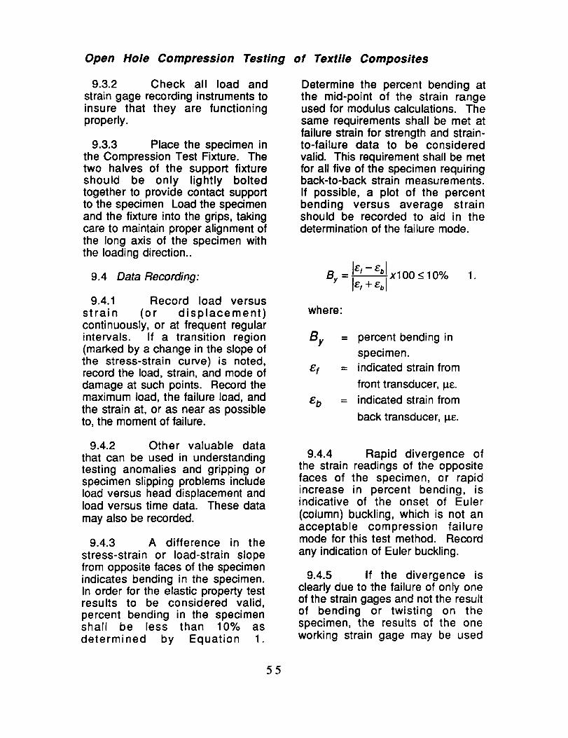
Open Hole Compression Testing of Textile Composites
9.3.2 Check all load and
strain gage recording instruments toinsure that they are functioningproperly.
9.3.3 Place the specimen inthe Compression Test Fixture. Thetwo halves of the support fixtureshould be only lightly boltedtogether to provide contact supportto the specimen Load the specimenand the fixture into the grips, takingcare to maintain proper alignment ofthe long axis of the specimen withthe loading direction..
9.4 Data Recording:
9.4.1 Record load versusstrain (or displacement)continuously, or at frequent regularintervals. If a transition region(marked by a change in the slope ofthe stress-strain curve) is noted,record the load, strain, and mode ofdamage at such points. Record themaximum load, the failure load, andthe strain at, or as near as possibleto, the moment of failure.
Determine the percent bending atthe mid-point of the strain rangeused for modulus calculations. Thesame requirements shall be met atfailure strain for strength and strain-to-failure data to be considered
valid. This requirement shall be metfor all five of the specimen requiringback-to-back strain measurements.If possible, a plot of the percentbending versus average strainshould be recorded to aid in thedetermination of the failure mode.
El -- Eb I
8, = + xl°° -<lOO/o
where:
By = percent bending in
specimen.
_'f = indicated strain from
front transducer, I_E.
_'b = indicated strain from
back transducer, I_¢.
,
9.4.2 Other valuable datathat can be used in understandingtesting anomalies and gripping orspecimen slipping problems includeload versus head displacement andload versus time data. These data
may also be recorded.
9.4.3 A difference in the
stress-strain or load-strain slopefrom opposite faces of the specimenindicates bending in the specimen.In order for the elastic property testresults to be considered valid,percent bending in the specimenshall be less than 10% as
determined by Equation 1.
9.4.4 Rapid divergence ofthe strain readings of the oppositefaces of the specimen, or rapidincrease in percent bending, isindicative of the onset of Euler
(column) buckling, which is not anacceptable compression failuremode for this test method. Record
any indication of Euler buckling.
9.4.5 If the divergence isclearly due to the failure of only oneof the strain gages and not the resultof bending or twisting on thespecimen, the results of the oneworking strain gage may be used
55

Open Hole Compression Testing of Textile Composites
and recorded as the longitudinalstrain. The data report shouldclearly indicate this circumstance.
9.4.6 Test specimens thatfail outside the hole are not validand shall be discarded.
10. Calculations
10.1 Calculations of the elastic
properties shall be made wheneverpossible using the followingequations:
10.1.1 Compression Strength DCalculate the ultimate compressionstrength using Eqn. 2 and reportresults to three significant digits.
.
where
Gutt = ultimate compressionstrength, MPa or KSI.
P = maximum load, N or Ibf.w = minimum specimen
width, mm or in.t = minimum specimen
thickness, mm or in.
Also report the strain range used inthe calculation.
10.1.2.1 The recommended strainranges should only be used formaterial that do not exhibit atransition region (a significantchange in the slope of the stress-strain curve) within therecommended strain range. If atransition region occurs within therecommended strain range, then amore suitable strain range shouldbe used and reported.
E = z_P I _G 3.
where:
E =
Z_P/ AI =
W =
t =
modulus of elasticity,MPa or KSI.
slope of the linear regionof the load--deformationcurve.gage length of strainmeasuring instrument,mm or in.minimum specimenwidth.
minimum specimenthickness.
10.1.2 Compressive Modulus ofElasticity m Calculate the modulusof elasticity from the stress-straindata using Equation 3. Data
gathered over the 1000 to 3000 !_strain range shall be used in thesecalculations. If data are notavailable at the exact strain rangeend points, use the closest availabledata point. Report the modulus ofelasticity to three significant figures.
10.1.3 Poisson's RatioDetermine the transverse strain
(strain in the plane of the specimenand perpendicular to the applied
load), Ex, at each point over thelongitudinal strain range of 1000
and 3000 I_E. If data are notavailable at the exact strain rangeend points, use the closest availabledata point. Calculate Poisson's ratiofrom Equation 4. Report the results
56

Open Hole Compression Testing of Textile Composites
of the calculation to three significantdigits.
AE xV- 4.
AEy
where:
Poisson's Ratio.
Slope of the strain-strain curve in the linear
region where _ydenotes the strain in the
loading direction and Exdenotes the strainperpendicular to theloading direction.
10.1.3.1 When determining thePoisson's ratio, match thetransverse strain with theappropriate longitudinal strain. Forinstance, match the output from asingle transverse strain gage withthe output from the singlelongitudinal gage mounted in anadjacent location on the same sideof the coupon. If back-to-backtransverse gages are employed,average their output and compare tothe average longitudinal strain.
Report this value to three significantfigures. Also report the method oflinear fit and the strain ranges overwhich the linear fit were determined.
10.1.5 Width to Diameter Ratio--Calculate the width to diameter ratio
using equation 5. Report both thenominal value and the actualcalculated value from measureddimensions.
.
where
specimen width (neglectingthe hole), mm or in.diameter of hole, mm or in.
10.2 Data Correction m The testdata shall be corrected for finitewidth using the following isotropicfinite width correction factor. Thisfactor is defined by equation 6.
d 3
[2 +(1-_) ].
10.1.4 Transition StrainWhere applicable, determine thetransition strain from either thebilinear longitudinal stress versuslongitudinal strain curve of thebilinear transverse strain versuslongitudinal strain curve. Create abest linear fit for each of the two
linear regions and extend the linesuntil they intersect. Determine thelongitudinal strain that correspondsto the intersection point and recordthis value as the transition strain.
where
O'oo
Ggross
W
d
= Infinite stress, MPa orKsi.
= Gross stress, MPa or
Ksi.
= specimen width(neglecting the hole),mm or in.
= diameter of hole, mmor in.
57

Open Hole Compression Testing of Textile Composites
10.3 Statistics- For each seriesof tests calculate and report to threesignificant digits the average value,standard deviation, and percentcoefficient of variation for eachproperty determined. Use equation7, 8, and 9 to determine thesevalues.
X=n
.
x2,, n 21Sn_ 1 = "CB- _)
.
11.2 As a minimum, the reportshall include the following:
11.2.1 A complete identificationof the material tested using termsdefined in reference publication2.1.3; Pastore, Christopher M.,"Illustrated Glossary of Textile Termsfor Composites", NASA CR 191539,Sept. 1993.
11.2.2 The number of specimenstested.
11.2.3 The fiber and resin densityused and how they were measured.
11.2.4 The average value andstandard deviation of the fibervolume fraction of the compositeand how it was measured.
%CoV = 100XSn_l / X 9.
where
X _.,
n --
Xi =
Sn-1 =
%COY=
sample mean (average).number of specimens.measured or derived
property.sample standarddeviation.sample coefficient ofvariation, in percent.
11.2.5 The average value ofultimate open hole strength, thecorrected value of the open holestrength, the standard deviation, andthe coefficient of variation for the
population.
11.2.6 The nominal and actualwidth to diameter ratio (W/d).
11.2.7 The nominal and actualdiameter to thickness ratio (d/t).
11.2.8 Failure mode and locationof failure for each specimen.
11. Report
11.1 The report shall include allappropriate parameters inaccordance with ASTM Test MethodD3410-94, making use of ASTMguides E1309, E1471, and E1434.
11.3 Where applicable, thefollowing may also be reported:
11.3.1 Ultimatestrain,
compressive
11.3.2 Compressive modulus ofelasticity,
58

Open Hole Compression
11.3.3 Poison's ratiocompression, and
11.3.4 Transition strain.
Testing of
in
Textile Composites
12. Precision and Bias
12.1 The following criteria shouldbe used for judging the acceptabilityof the results:
12.1.1 Repeatability _ The resultsshould be considered suspect if twoaverages obtained by the sametesting laboratory differ by more than2 standard deviations.
12.1.2 Reproducibility _ Theresults should be considered
suspect if two averages obtained bydifferent testing laboratories differ bymore than 2.8 standard deviations.
59

Standard Test Method for Filled Hole TensionTesting of Textile Composites
1. Scope
1.1 This test method determinesthe filled hole tension strength oftextile composite materials. Thisrecommendation does not attempt toaddress all aspects of filled holetension testing of all textilearchitectures. Rather, proceduresare recommended to establish astandard method of filled holetension testing between testinglaboratories. This method is limitedto the textile architectures identified
in Chapter 2 of this document.
1.2 This test method does not
purport to address all of the safetyissues associated with it's use. It isthe responsibility of the user toestablish appropriate safety andhealth practices prior to initiatingtesting.
2.1.3 Pastore, Christopher M.,"Illustrated Glossary of Textile Termsfor Composites", NASA CR 191539,Sept. 1993.
2.1.4 Masters, John E.,"Strain Gage Practice for TextileComposites', NASA CR 198286,Feb. 1996
2.2 ASTM Standards:
D792 Test Methods for Specific
Gravity and Density of Plastics byDisplacements.
D883 Terminology Relating toPlastics.
D2584 Test Method for IgnitionLoss of Cured Reinforced Resins.
2. Reference Documents
2.1 Reference Publications:
D2734 Test Methods for VoidContent of Reinforced Plastics.
D3039 Test Method for Tensile
Properties of Polymer MatrixComposite Materials.
2.1.1 Minguet, Pierre J., Fedro,Mark J., Gunther, Christian K., "TestMethods for Textile Composites"NASA CR 4609, July 1994.
2.1.2 Portanova, M.A., "StandardMethods for Filled Hole Tension
Testing of Textile Composites",NASA CR 198263, Dec. 1995.
D3171 Test Method for FiberContent of Resin Matrix Compositesby Matrix Digestion.
D3878 Terminology of High-Modulus Reinforced Fiber and Their
Composites.
D5766 Standard Test Method for
Open Hole Tensile Strength ofPolymer Matrix CompositeLaminates
60

Filled Hole Tension Testing of Textile Composites
E6 Terminology Relating toMethods of Mechanical Testing.
E177 Practice for use of TermsPrecision and Bias in ASTM TestMethods.
E456 Terminology Relating toQuality and Statistics.
E1434 Guide for Developmentof Standard Data Records for
Computerization of Mechanical TestData for High-Modulus Fiber-Reinforced Composite Materials.
3. Terminology
3.1 Definitions m Definitionsused in this test method are defined
by various ASTM methods. ASTMmethod D3878 defines terms
relating to high-modulus fiber andtheir composites. ASTM methodD883 defines terms relating toplastics. ASTM method E6 definesterms relating to mechanical testing.ASTM methods E456 and E177
define terms relating to statistics. Inthe event of a conflict betweendefinitions of terms, ASTM methodD3878 shall have precedence overthe other standards.
3.2 Description of Terms Specificto This Standard:-- Terms relatingspecifically to textile composites aredefined by reference publication2.1.3; Pastore, Christopher M.,"Illustrated Glossary of Textile Termsfor Composites", NASA CR 191539,Sept. 1993.
3.3 The Unit Cell _ In theory,textile composites have a repeatinggeometrical pattern based onmanufacturing perameters. Thisrepeating pattern is often called thematerial's "unit cell". It is defined asthe smallest section of architecturerequired to repeat the textile pattern.Handling and processing can distortthe "theoretical" unit cell. Althoughsome parameters, such as tow sizeand fiber angle, may be explicitlydefined, calculation of unit celldimensions tend to be somewhatsubjective. Unit cell dimensions arebased on varying interpretations ofthe textile architecture. For adescription of the method used todetermine the unit cell dimensionsrefer to Chapter 2 of this document.
4. Summary of Test Method
4.1 Filled Hole Tension Tests of a
textile composite materials areperformed in accordance with ASTMStandard Test Method D5766. Atitanium Hilok fastener is installed in
the open hole tension specimendescribed in Section 6 of this reportand illustrated in Figure 1. Thefastener is torqued to 25 - 30 in°lbf.The specimen is then mounted inthe grips of the testing machine andloaded in uniaxial tension to failure.Ultimate strength is calculatedbased on the gross cross-sectionalarea, disregarding the hole, andthen corrected for finite width effects.
61

Filled Hole Tension Testing of Textile Composites
5. Significance and Use
5.1 Textile composites have aless homogeneous nature thancomposites constructed from pre-preg tape. Consequently, standardcomposite testing methods may notbe adequate to characterize thesematerials. Each textile architecture
has an independent unit cell size.This repeating inhomogeneity maycause variability in the test results ifspecimens are sized solely by usingguidelines established for tapematerials.
5.2 This test method is designedto produce filled hole tensionstrength data for materialspecifications, research anddevelopment, design, and qualityassurance. The factors thatinfluence tensile properties, andtherefore should be reported are:textile architecture as described bysection 3.2, the method of materialfabrication and overall thickness,specimen geometry, specimenpreparation, specimen fiber volumefraction and void content, theenvironment of testing and speed oftesting. Properties that may bederived from this test method
include the following:
5.2.1 Filled hole (notched) tensilestrength.
5.3 This test method is the resultof studies conducted at twoindependent testing laboratories.The primary contributor of test datawas Boeing Defense and SpaceGroup in Philadelphia, PA.Supplemental data was obtainedfrom Lockheed Aeronautical
Systems in Marietta, GA. Most of the
data was derived from tests on twodimensional triaxial braids and three
dimensional interlocking weaves.Lockheed also evaluated a threedimensional braid. An evaluation of
test method was made using resultsfrom each of the contributors and isavailable in reference document
2.1.2 Portanova, M.A., "StandardMethods for Filled Hole Tension
Testing of Textile Composites",NASA CR 198263, Dec. 1995.
5.4 This method is recommendedfor experiments conducted on 2-Dbraids, 3-D weaves, and similartextile architectures evaluated inreference document 2.1.2.Specifically, this test method hasonly been evaluated using thebraids and weaves described in
Chapter 2 of this document.
5.5 This test method has onlybeen evaluated under roomtemperature - dry test conditions. Itsapplicability to testing textilecomposites under elevatedtemperature and moistureconditions has not beenestablished.
6. Apparatus
6.1 The test apparatus used shallbe in accordance with ASTM TestMethod D3039. However, the
procedure herein does not measurematerial response, so strain ordeflection measurement relateddiscussion in Test Method D3039 donot apply. Additionally, amicrometer or gage capable ofdetermining the hole diameter to0.001 in. is required.
62

Filled Hole Tension Testing of Textile Composites
7. Sampling & Test Specimen
7.1 Sampling n Test at least fivespecimens per series unless validresults can be obtained using lessspecimens, such as by using adesigned experiment. Forstatistically significant data use theprocedure outlined in ASTMpractice E 122. Report the methodof sampling.
7.2 Specimen Geometry _ Thetest specimen geometry shall be inaccordance with ASTM Test Method
D5766. Specifically, the straightsided specimen geometry illustratedin Figure 1 shall be as follows:
7.2.2 Recommenced Dimensionsm The specimen width shall be36+0.1 mm [1.50!-_0.005 in.] and thelength range is 200 -- 300 mm [8.0
12.0 in.]. The centrally locatedhole shall be 6.0+0.006 mm
[0.250!-_0.003 in.] diameter and belocated within 0.13 mm [0.005 in.] ofthe axial centerline of the testspecimen.
7.2.3 Ratio of Specimen Widthto Unit Cell Size _ Therecommended specimen width wasdetermined through the evaluationof 2-D braided materials whose unitcells ranged from 0.415 inch to
_ Length --_
" I _ole _Width
End Tab 1/2 Width (w/D ratio = 6)
Figure 1. Filled Hole Tension Test Specimen.
7.2.1 Specimen Width &Thickness _ A specimen width tohole diameter ratio (W/d) of 6 mustbe maintained. A hole diameter tothickness ratio (d/t) of 1.5- 3.0 isrecommended. The test specimenshall have a constant rectangularcross section with a specimen widthvariation of no more than + 1% anda specimen thickness variation of nomore than + 4%.
0.829 inch in width. The evaluationof textile composites whose unitcells are wider may require testspecimens of greater width.
7.2.4 Filled Hole _ The throughhole shall be filled with a 0.250 in.diameter titanium Hilok fastener.
This fastener shall be torque to 25-30 inolbf.
63

Filled Hole Tension Testing of Textile Composites
7.3 Specimen Fabrication -- Thespecimens may be moldedindividually without cut edges ormachined from a plate after bondingon tab material. If cut from a plate,
precautions must be take to avoidnotched, undercuts, or rough edges.When machined, each specimenshould be saw cut oversized and
ground to the final dimensions.
7.4 Hole Preparation _ Due tothe dominant presence of the notch,consistent preparation of the hole,without damage to the laminate, isimportant to meaningful results.Damage due to hole preparation willaffect strength results. Some typesof damage, such as delaminations,can blunt the stress concentration atthe hole and increase the load-
carrying capacity of the coupon.
7.4 End Tabs _ Tabs are not
required but may be used. Typicallythe hole induces a stress risersufficient to force failure in the
notched region.
8. Conditioning
8.1 Standard ConditioningProcedure _ Unless a differentenvironment is required, the testspecimens shall be conditioned inaccordance with ASTM Procedure Cof Test Method D5229 / D5229M..Store and test at standard laboratoryconditions of 23+1° C [73.4+1.8 ° F]and 50!-_10 % relative humidity.
9. Procedure
9.1 Genera/Instructions:
9.1.1 Report any deviations fromthis test method, whether intentionalor inadvertent.
9.1.2 Following final specimenmachining and any conditioning, butbefore testing, determine the areaas A = w x h at three places in thegage section and report the area asthe average of these threedeterminations, to an accuracy of ___0.0001 in. in thicknessmeasurements and _+0.001 in. inwidth measurements. Record theminimum values of cross-sectionalarea so determined. Also measureand report the spcimen holediameter to the nearest 0.001 in.Inspect the hole and areas adjacentto the hole for delaminations.Report the location and size of anydelaminations found.
9.2 Speed of Testing _ Testingspeed shall set at a constantdisplacement rate of between 0.02and 0.05 in/min, as required to
produce failure within 1 to 10 min.
9.3 Specimen Insertion _ Placethe specimen in the grips of thetesting machine, taking care to alignthe long axis of the grippedspecimen with the test direction.Tighten the grips, recording thepressure used on pressurecontrollable (hydraulic or
pneumatic) grips.
9.4 Loading _ Apply the load tothe specimen at the specified rateuntil failure, while recording data.
9.5 Data Recording--
9.5.1 If possible, record loadcontinuously, or at frequent regular
64

Filled Hole Tension Testing of Textile Composites
intervals. Record the maximum load
and the failure load at, or as near as
possible to, the moment of rupture.
9.5.2 Other valuable data that can
be used in understanding testinganomalies and gripping orspecimen slipping problems includeload versus head displacement andload versus time data. These data
may also be recorded.
9.6 Failure Mode _ Record themode and location of failure of the
specimen. The failure is oftenheavily influenced by delaminationand the failure mode may exhibitmuch delamination. Failures that donot occur at the hole are not
acceptable failure modes and thedata shall be noted as invalid.
10. Calculations
Calculations shall be made usingthe following equations:
10.1 Ultimate Strength mCalculate the ultimate filled hole
tensile strength using Equation 1.
Report results to three significantdigits.
PmaxGult -- 1.
wt
where:
£Tu/t =
P max _
ultimate open hole tensilestrength, MPa or Ksi.maximum load prior tofailure, N or Ibf.
w = specimen width(neglecting the hole), mmor in.
t = specimen thickness, mmor in.
10.2 Data Correction _ The testdata shall be corrected for finite
width using the following isotropicfinite width correction factor. This
factor is defined by equation 2.
O'oo
d 3
[2+(1-_-) ]
d
Ggross 3(1 -_)
where
.
ooo = Infinite stress, MPa orKsi.
Ggross = Gross stress, MPa orKsi.
W = specimen width(neglecting the hole),mm or in.
d = diameter of hole, mmor in.
10.3 Width to Diameter Ratio--Calculate the actual width to
diameter ratio using equation 3.Report both the nominal ratiocalculated using nominal valuesand the actual ratio calculated withmeasured dimensions.
.
where
65

Filled Hole Tension Testing of
specimen width (neglectingthe hole), mm or in.diameter of hole, mm or in.
10.4 Statistics _ For each series
of tests calculate and report to three
significant digits the average value,standard deviation, and percentcoefficient of variation for each
property determined. Use equations4, 5, and 6 to determine thesevalues.
n
.
.
%CoV = 100XSn_ 1 / _(
where
°
X
n =
Xi =
Sn-1 =
%CoY =
sample mean (average).number of specimens.measured or derived
property.sample standarddeviation.
sample coefficient ofvariation, in percent.
Textile Composites
D5766, making use of ASTM guidesE1309, E1471, and E1434.
11.2 As a minimum, the reportshall include the following:
11.2.1 A complete identificationof the material tested using termsdefined in reference publication2.1.3; Pastore, Christopher M.,"Illustrated Glossary of Textile Terms
for Composites", NASA CR 191539,Sept. 1993.
11.2.2 The number of specimenstested.
11.2.3 The fiber and resin density
used and how they were measured.
11.2.4 The average value andstandard deviation of the fiber
volume fraction of the compositeand how it was measured.
11.2.5 The average value ofultimate filled hole strength, thecorrected value of the filled hole
strength, the standard deviation, andthe coefficient of variation for the
population.
11.2.6 The nominal and actual
width to diameter ratio (W/d).
11.2.7 The nominal and actualdiameter to thickness ratio (d/t).
11.2.8 Failure mode and location
of failure for each specimen.
11. Report
t1.1 The report shall include all
appropriate parameters inaccordance with ASTM Test Method
12. Precision and Bias
12.1 The following criteria should
be used for judging the acceptabilityof the results:
66

Filled Hole Tension Testing of Textile Composites
12.1.1 Repeatability n Theresults should be considered
suspect if two averages obtained bythe same testing laboratory differ bymore than 2 standard deviations.
12.1.2 Reproducibility _ Theresults should be consideredsuspect if two averages obtained bydifferent testing laboratories differ bymore than 2.8 standard deviations.
67

Standard Test Method for Bolt-Bearing Testingof Textile Composites
1. Scope
1.1 This test method determinesthe bolt-bearing strength of textile
composite materials. Thisrecommendation does not attempt toaddress all aspects of bolt-bearingtesting of all textile architectures.Rather, procedures arerecommended to establish astandard method of bolt -bearingtesting between testing laboratories.This method is limited to the textilearchitectures identified in Chapter 2of this document.
1.2 This test method does notpurport to address all of the safetyissues associated with it's use. It is
the responsibility of the user toestablish appropriate safety andhealth practices prior to initiatingtesting.
2. Reference Documents
2.1 Reference Publications:
2.1.1 Minguet, Pierre J., Fedro,Mark J., Gunther, Christian K., "TestMethods for Textile Composites"NASA CR 4609, July 1994.
2.1.2 Portanova, M.A., "StandardMethods for Bolt-Bearing Testing ofTextile Composites", NASA CR198266, Dec. 1995.
2.1.3 Pastore, Christopher M.,"Illustrated Glossary of Textile Termsfor Composites", NASA CR 191539,Sept. 1993.
2.2 ASTM Standards:
D792 Test Methods for Specific
Gravity and Density of Plastics byDisplacements.
D883 Terminology Relating toPlastics.
D2584 Test Method for IgnitionLoss of Cured Reinforced Resins.
D2734 Test Methods for VoidContent of Reinforced Plastics.
D3039 Test Method for TensileProperties of Polymer MatrixComposite Materials.
D3171 Test Method for FiberContent of Resin Matrix Composites
by Matrix Digestion.
D3878 Terminology of High-Modulus Reinforced Fiber and Their
Composites.
D5766 Standard Test Method for
Open Hole Tensile Strength ofPolymer Matrix CompositeLaminates
E6 Terminology Relating toMethods of Mechanical Testing.
E177 Practice for use of TermsPrecision and Bias in ASTM TestMethods.
E456 Terminology Relating toQuality and Statistics.
68

Bolt-Bearing Testing of Textile Composites
E1434 Guide for Development ofStandard Data Records forComputerization of Mechanical TestData for High-Modulus Fiber-Reinforced Composite Materials.
3. Terminology
3.1 Definitions _ Definitionsused in this test method are definedby various ASTM methods. ASTMmethod D3878 defines termsrelating to high-modulus fiber andtheir composites. ASTM methodD883 defines terms relating toplastics. ASTM method E6 definesterms relating to mechanical testing.ASTM methods E456 and E177
define terms relating to statistics. Inthe event of a conflict betweendefinitions of terms, ASTM methodD3878 shall have precedence overthe other standards.
3.2 Description of Terms Specificto This Standard m Terms relatingspecifically to textile composites aredefined by reference publication2.1.3; Pastore, Christopher M.,"Illustrated Glossary of Textile Termsfor Composites", NASA CR 191539,Sept. 1993.
3.3 The Unit Cell _ In theory,textile composites have a repeatinggeometrical pattern based onmanufacturing perameters. Thisrepeating pattern is often called thematerial's "unit cell". It is defined asthe smallest section of architecture
required to repeat the textile pattern.Handling and processing can distortthe "theoretical" unit cell. Althoughsome parameters, such as tow sizeand fiber angle, may be explicitlydefined, calculation of unit cell
dimensions tend to be somewhat
subjective. Unit cell dimensions arebased on varying interpretations ofthe textile architecture. For adescription of the method used todetermine the unit cell dimensionsrefer to Chapter 2 of this document.
4. Summary of Test Method
4.1 Two flat, constant rectangularcross-section coupons withcenterline holes located near their
ends, as shown in Figure 1, areloaded at the holes in bearing. Thebearing load is applied throughclose-tolerance, lightly-torquedfasteners that are reacted in double
shear by a fixture that is shown inthe figure. The bearing load iscreated by pulling the assembly intension in a testing machine.
4.2 The applied load is monitored.The load is normalized by theprojected hole area to create aneffective bearing stress. Theassembly is loaded until a loadmaximum has clearly been reached,whereupon the test is terminated.This prevents masking of the truefailure mode by large-scale holedistortion and permits representativefailure mode assessment. The
ultimate bearing strength of thematerial is determined from the
maximum load carried prior to testtermination.
5. Significance and Use
5.1 Textile composites have aless homogeneous nature thancomposites constructed from pre-preg tape. Consequently, standard
69

Bolt-Bearing Testing of Textile Composites
composite testing methods may notbe adequate to characterize thesematerials. Each textile architecturehas an independent unit cell size.This repeating inhomogeneity maycause variability in the test results ifspecimens are sized solely by usingguidelines established for tapematerials.
5.2 This test method is designed
to produce bolt-bearing strengthdata for materials specifications,research and development, qualityassurance, and structural designand analysis.
5.3 Factors that influence thebearing strength , and thereforeshould be reported are: textilearchitecture as described by section3.2, the method of materialfabrication, and overall thickness,
specimen geometry (thickness,width, hole diameter, edge distanceratio, pitch distance ratio, and thediameter to thickness ratio), fastenertorque, hole clearance, hole quality,specimen fiber volume fraction andvoid content, the environment oftesting and speed of testing.Properties that may be derived fromthis test method include thefollowing:
5.3.1 Bearing ultilmate strength.
5.4 This test method is the result
of a study conducted at BoeingDefense and Space Group inPhiladelphia, PA. All of the datawas derived from tests on twodimensional triaxial braids. Threedifferent specimen configurationswere examined, as were variouspitch distance (W/D) and edgedistance (e/D) ratios. An evaluation
of test method was made usingresults from Boeing's study and isavailable in reference document2.1.2, Portanova, M.A., "StandardMethods for Bolt-Bearing Testing ofTextile Composites", NASA CR198266, Dec. 1995.
5.5 This method is recommendedfor experiments conducted on 2-Dbraids, 3-D weaves, and similartextile architectures evaluated inreference document 2.1.2.Specifically, this test method hasonly been evaluated using thebraids and weaves described in
Chapter 2 of this document.
5.6 This test method has onlybeen evaluated under room
temperature - dry test conditions. Itsapplicability to testing textilecomposites under elevatedtemperature and moistureconditions has not beenestablished.
6, Apparatus
6.1 The test apparatus used shallbe in accordance with ASTM TestMethod D3039. However, the
procedure herein does not measurematerial response, so strain ordeflection measurement relateddiscussion in Test Method D3039 donot apply. Additionally, amicrometer or gage capable ofdetermining the hole diameter to0.001 in. is required.
7. Sampling & Test Specimen
7.1 Sampling _ Test at least fivespecimens per series unless valid
?0

Bolt-Bearing Testing of Textile Composites
results can be obtained using lessspecimens, such as by using adesigned experiment. Forstatistically significant data use theprocedure outlines in ASTM practiceE 122. Report the method ofsampling.
7.2 Specimen Geometry m Thetest specimen geometry is illustratedin Figure 1.
7.2.1 Specimen Width, Thicknessand Hole Diameter- A pitchdistance ratio, (specimen width tohole diameter ratio, W/d) of 6 must
be maintained. An edge distanceratio (specimen edge distance tohole diameter ratio, e/D) of 3 orgreater should be used. Thesedimensions are illustrated in Figure2. A hole diameter to thickness ratio(d/t) of 1.5- 3.0 is recommended.The test specimen shall have aconstant rectangular cross sectionwith a specimen width variation ofno more than + 1% and a specimenthickness variation of no more than+ 4%.
7.2.2 Recommenced DimensionsThe specimen width shall be
36+0.1 mm [1.50+0.003 in.]. The
7350
±O.m
7.75±0.0_
1.50:1: O.O_
6.2S
:003
0.75
± O.m
2.00:0.03
R_ffEENIslON S ARE
IN INCHES
USE I'WDRAU UCGRIPS IN TES TIN3
_ 0.375 STK
4340STEELLCAD
/ PLATE
l.Nd NATE
ICKNESS
"q_J_..T"--_o,,,._:'1_i_.El m_=TE. HCXJE
ASTENER:ITAN UM HLOK
434O
STEELLOAD
/ PLATE
Figure 1. Bolt-Bearing Test Specimen.
7]

Bolt-Bearing Testing of Textile Composites
specimen length shall be 89-+1 mm[3.50+0.03 in.]. The centrallylocated holes shall be 6.0-_.06 mm
[0.250-+0.003 in.] diameter and belocated within 0.13 mm [0.005 in.] ofthe axial centerline of the test
specimen. The hole edge tospecimen edge distance shall be15.9 ram-+0.1 mm [0.625-+0.005 in.].
7.2.3 Ratio of Specimen Widthto Unit Cell Size m Therecommended specimen width wasdetermined through the evaluationof 2-D braided materials whose unitcells ranged from 0.415 inch to0.829 inch in width. The evaluationof textile composites whose unitcells are wider may require test
specimens of greater width.
7.2.4 Fastener and Fastener
Torque _ Titanium Hilok fastenersshould be used in the tests. The0.250 in. diameter fasteners shall be
torque to 25-30 inolbf.
7.3 Specimen Fabrication m Thespecimens may be moldedindividually without cut edges ormachined from a plate after bondingon tab material. If cut from a plate,precautions must be take to avoidnotched, undercuts, or rough edges.When machined, each specimenshould be saw cut oversized and
ground to final dimensions.
7.4 Hole Preparation mConsistent preparation of the hole,without damage to the laminate, isimportant to meaningful results.Damage due to hole preparation willaffect strength results. Some typesof damage, such as delaminations,
can blunt the stress concentration atthe hole and increase the load-
carrying capacity of the coupon.
8. Conditioning
8.1 Standard ConditioningProcedure _ Unless a differentenvironment is required, the testspecimens shall be conditioned inaccordance with ASTM Procedure Cof Test Method D5229 / D5229M..Store and test at standard laboratoryconditions of 23_+1° C [73.4_+1.8 ° F]and 50-+10 % relative humidity.
9. Procedure
9.1 General lnstructions:
9.1.1 Report any deviations fromthis test method, whether intentionalor inadvertent.
Figure 2. Bolt Bearing SpecimenDimensions.
9.1.2 Following final specimenmachining and any conditioning, butbefore testing, measure thespecimen width and thickness in thevicinity of the hole. Measure thehole diameter, the distance from thehole edge to the closest couponside, and the distance from the holeedge to the coupon end. Inspect the
?2

Bolt-Bearing Testing of Textile Composites
hole to determine that it has beenproperly machined and is free fromdelamination. Measure the fastener
diameter at the bearing contactlocation. The accuracy of allmeasurements shall be within 1% ofthe dimension. Record thedimensions to three significantfigures.
9.2 Speed of Testing _ Testingspeed shall set at a constantdisplacement rate of between 0.02and 0.05 in/min, as required toproduce failure within 1 to 10 min.
9.3 Specimen Insertion _ Placethe specimen in the grips of thetesting machine, taking care to alignthe long axis of the grippedspecimen with the test direction.Tighten the grips, recording thepressure used on pressurecontrollable (hydraulic orpneumatic) grips.
9.4 Loading _ Apply the load tothe specimen at the specified rateuntil failure, while recording data.
9.5 Data Recording m
9.5.1 If possible, record loadcontinuously, or at frequent regularintervals. Record the maximum loadand the failure load at, or as near aspossible to, the moment of rupture.
9.5.2 Other valuable data that can
be used in understanding testinganomalies and gripping orspecimen slipping problems includeload versus head displacement andload versus time data. These datamay also be recorded.
9.6 Failure Mode _ Record themode and location of failure of thespecimen.
10. Calculations
10.1 Calculations shall be made
using the following equations.
10.1.1 Bearing StrengthCalculate the bolt-bearing strengthusing the following equation. Reportresults to three significant digits.
.
where
Gb = ultimate bearing strength,MPa or Ksi.
P = maximum load prior tofailure, N or Ibf.
d -- hole diameter, mm or in.t = specimen thickness, mm
orin.
10.1.2 Width to Diameter RatioCalculate the width to diameter ratio(Fig. 1) using equation 2. Reportboth the nominal value and theactual calculated value frommeasured dimensions.
W//drati = W_-d
.
where
W Be
d =
specimen width (neglectingthe hole), mm or in.diameter of hole, mm or in.
73

Bolt.Bearing Testing of Textile Composites
10.1.3 Edge Distance to HoleDiameter Ratio w Calculate thespecimen edge distance to holediameter ratio (Fig. 1) usingequation 3. Report both the nominalvalue and the actual calculatedvalue from measured dimensions.
e_ rat/° - d
where
e = distance from hole tospecimen edge, mm or in.
d = diameter of hole, mm or in.
10.1.4 Hole Diameter toThickness Ratio _ Calculate the
specimen hole diameter to thicknessratio using equation 4. Report themeasured value.
dr.'o=T .
where
d = diameter of hole, mm or in.t = thickness, mm or in.
10.2 Statistics _ For each seriesof tests calculate and report to three
significant digits the average value,standard deviation, and percentcoefficient of variation for each
property determined. Use equations5, 6, and 7 to determine thesevalues.
-nS(
Sn_ 1 = CT )
°
.
%CoV = 100XSn_ 1 / X
where
.
n
Xi =
Sn-1 =
%COY=
sample mean (average).number of specimens.measured or derived
property.sample standarddeviation.sample coefficient ofvariation, in percent.
11. Report
11.1 The report shall include allappropriate parameters making useof ASTM guides E1309, E1471, andE1434.
11.2 As a minimum, the reportshall include the following:
11.2.1 A complete identificationof the material tested using termsdefined in reference publication2.1.3; Pastore, Christopher M.,"Illustrated Glossary of Textile Termsfor Composites", NASA CR 191539,Sept. 1993.
?4

Bolt-Bearing Testing of Textile Composites
11.2.2 The number of specimenstested.
11.2.3 The fiber and resin densityused and how they were measured.
11.2.4 The average value andstandard deviation of the fiber
volume fraction of the compositeand how it was measured.
11.2.5 The average value ofbearing strength, the standarddeviation, and the coefficient ofvariation for the population.
11.2.6 The nominal and actualwidth to diameter ratio.
11.2.7 The nominal and actual
edge distance to diameter ratio.
11.2.8 Failure mode and location
of failure for each specimen.
12. Precision and Bias
12.1 The following criteria shouldbe used for judging the acceptabilityof the results:
12.1.1 Repeatability D The resultsshould be considered suspect if twoaverages obtained by the sametesting laboratory differ by more than2 standard deviations.
12.1.2 Reproducibility _ Theresults should be consideredsuspect if two averages obtained bydifferent testing laboratories differ bymore than 2.8 standard deviations.
?5

Standard Test Method for Interlaminar TensionTesting of Textile Composites
1. Scope
1.1 This test method is arecommended procedure fordetermining the out-of-planestrength of textile compositematerials. This recommendationdoes not attempt to address allaspects of out-of-plane testing of alltextile architectures. Rather,
procedures are recommended toestablish a standard method of bolt
-bearing testing between testinglaboratories. This method is limitedto the textile architectures identified
in Chapter 2 of this document.
1.2 This test method does not
purport to address all of the safetyissues associated with it's use. It isthe responsibility of the user toestablish appropriate safety andhealth practices prior to initiatingtesting.
2. Reference Documents
2.1 Reference Publications:
2.1.1 Minguet, Pierre J., Fedro,Mark J., Gunther, Christian K., "TestMethods for Textile Composites"NASA CR. 4609, July 1994.
2.1.2 Jackson, W. C. andPortanova, M. A., "Out-of-PlaneProperties," NASA ConferencePublication 3311, October 1995, pp.315 - 349.
2.1.3 Pastore, Christopher M.,"Illustrated Glossary of Textile Termsfor Composites', NASA CR. 191539,Sept. 1993.
2.1.4 Jackson, W.C. and Ifju, P."Through-the-Thickness TensileStrength of Textile Composites,"NASA TM 109115, May 1994
2.1.5 Jackson, W.C. and Martin,R.H., "An Interlaminar TensileStrength Specimen," CompositeMaterials: Testing and Design(Eleventh Volume), ASTM STP1206, E.T. Camponeschi, Jr., Ed.,American Society for Testing andMaterials, Philadelphia, Dec. 1993,pp. 333-354.
2.2 ASTM Standards:
D792 Test Methods for SpecificGravity and Density of Plastics byDisplacements.
D883 Terminology Relating toPlastics.
D2584 Test Method for IgnitionLoss of Cured Reinforced Resins.
D2734 Test Methods for VoidContent of Reinforced Plastics.
D3039 Test Method for Tensile
Properties of Polymer MatrixComposite Materials.
76

Interlaminar Tension Testing of Textile Composites
D3171 Test Method for Fiber
Content of Resin Matrix Compositesby Matrix Digestion.
D3878 Terminology of High-Modulus Reinforced Fiber and TheirComposites.
E6 Terminology Relating toMethods of Mechanical Testing.
E177 Practice for use of TermsPrecision and Bias in ASTM TestMethods.
E456 Terminology Relating toQuality and Statistics.
E1434 Guide for Developmentof Standard Data Records forComputerization of Mechanical TestData for High-Modulus Fiber-Reinforced Composite Materials.
3. Terminology
3.1 Definitions _ Definitionsused in this test method are definedby various ASTM methods. ASTMmethod D3878 defines termsrelating to high-modulus fiber andtheir composites. ASTM methodD883 defines terms relating toplastics. ASTM method E6 definesterms relating to mechanical testing.ASTM methods E456 and E177
define terms relating to statistics. Inthe event of a conflict betweendefinitions of terms, ASTM methodD3878 shall have precedence overthe other standards.
3.2 Descnption of Terms Specificto This Standard _ Terms relatingspecifically to textile composites aredefined by reference publication2.1.3; Pastore, Christopher M.,"Illustrated Glossary of Textile Termsfor Composites", NASA CR 191539,Sept. 1993.
3.3 The Unit Cell _ In theory,textile composites have a repeatinggeometrical pattern based onmanufacturing perameters. Thisrepeating pattern is often called thematerial's "unit cell". It is defined asthe smallest section of architecture
required to repeat the textile pattern.Handling and processing can distortthe "theoretical" unit cell. Althoughsome parameters, such as tow sizeand fiber angle, may be explicitlydefined, calculation of unit celldimensions tend to be somewhatsubjective. Unit cell dimensions arebased on varying interpretations ofthe textile architecture. For a
description of the method used todetermine the unit cell dimension
refer to Chapter 2 of this document.
4. Summary of Test Method
4.1 Out-of-Plane Testing of textilecomposite materials are performedin accordance with followingprocedure. The out-of-planespecimen illustrated in Figure 1 isused for this test method. Through-the-thickness tension is induced inthe test section through theapplication of a constant moment,which attempts to open the curvedsection of the specimen (Fig. 2).
??

Interlaminar Tension Testing of Textile Composites
Radial stresses, Gr, are determinedusing the closed-form analysis givenby Equation 1.
5. Significance and Use
5.1 Textile composites have aless homogeneous nature thancomposites constructed from pre-preg tape. Consequently, standardcomposite testing methods may notbe adequate to characterize thesematerials. Each textile architecturehas an independent unit cell size.This repeating inhomogeneity maycause variability in the test results ifspecimens are sized solely by usingguidelines established for tapematerials.
5.2 This test method is designed
to produce out-of-plane strengthdata for material specifications,research and development and
design. The factors that influenceout-of-plane properties, andtherefore should be reported are:textile architecture as described bysection 3.2, the method of materialfabrication and overall thickness,
specimen geometry, specimenpreparation, specimen fiber volumefraction and void content, theenvironment of testing and speed of
testing.
5.3 This test method is the resultof an evaluation of studiesconducted at Boeing Defense and
Space Group in Philadelphia, PA.and NASA Langley ResearchCenter, Hampton VA. Threedifferent specimen configurationswere examined. The results of
these investigations aresummarized in reference documents2.1.1 and 2.1.2.
5.4 This method is onlyrecommended for experimentsconducted on two dimensionaltextile architectures. Specifically,this test method has only beenevaluated using the braidsdescribed in Chapter 2 of thisdocument.
5.5 This test method has onlybeen evaluated under roomtemperature - dry test conditions. Itsapplicability to testing textilecomposites under elevatedtemperature and moistureconditions has not beenestablished.
6. Apparatus
6.1 Apparatus shall be fabricatedto the dimensions given by Figure 2.
7. Sampling & Test Specimen
7.1 Sampling J Test at least fivespecimens per series unless validresults can be obtained using less
specimens, such as by using adesigned experiment. Forstatistically significant data use theprocedure outlines in ASTM practiceE 122. Report the method ofsampling.
7.2 Specimen Geometry m Thetest specimen geometry shall be asshown in Figure 1.
?8
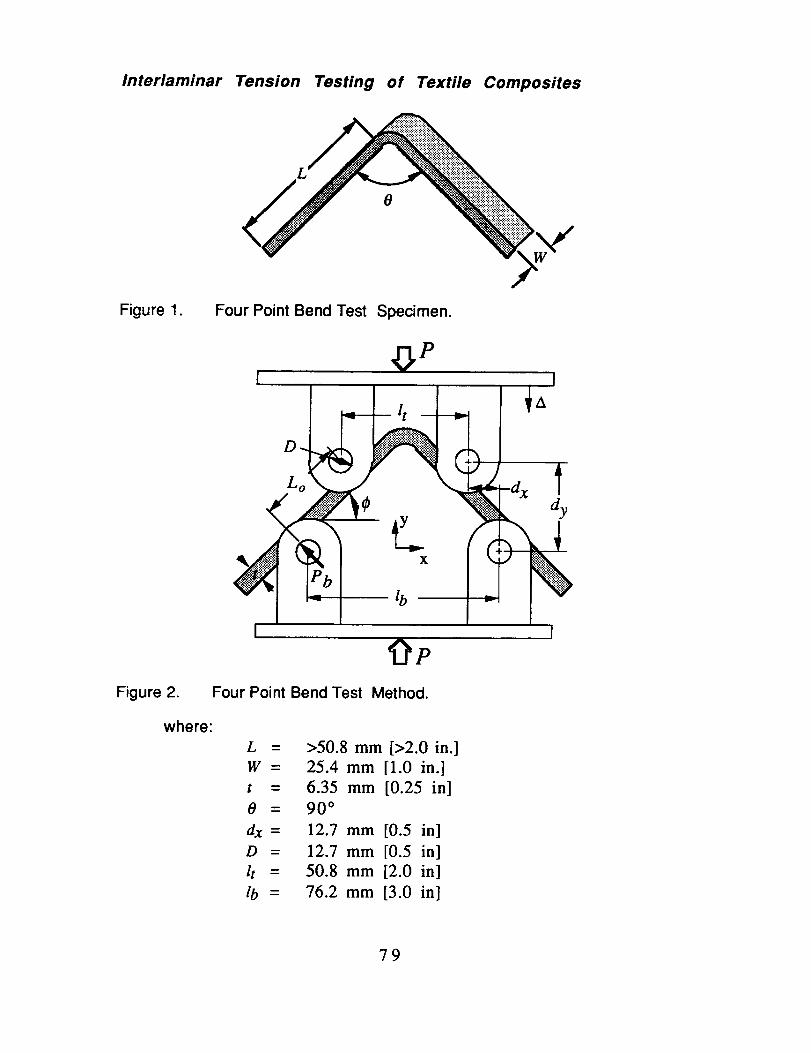
Interlaminar Tension Testing of Textile Composites
0
Figure 1. Four Point Bend Test Specimen.
I I
I I9e
Figure 2. Four Point Bend Test Method.
where:
L
W=
t =
0 =
_=D =
/t =_=
>50.8 mm [>2.0 in.]
25.4 mm [1.0 in.]
6.35 mm [0.25 in]
90 °
12.7 mm [0.5 in]
12.7 mm [0.5 in]
50.8 mm [2.0 in]
76.2 mm [3.0 in]
79

Interlaminar Tension Testing of Textile Composites
7.3 Specimen Fabrication D Thespecimens may be moldedindividually without cut edges ormachined from an angle shapedbeam. If cut from a beam,
precautions must be take to avoidnotched, undercuts, or rough edges.When machined, each specimenshould be saw cut oversized and
ground to final dimensions. The testspecimen shall have a constantrectangular cross section with aspecimen width variation of no morethan _+ 1% and a specimenthickness variation of no more than+ 4%.
7.2.3 Ratio of Specimen Widthto Unit Cell Size _ Therecommended specimen width wasdetermined through the evaluationof 2-D braided materials whose unit
cells ranged from 0.415 inch to0.829 inch in width. The evaluationof textile composites whose unitcells are wider may require testspecimens of greater width.
8. Conditioning
8.1 Standard ConditioningProcedure _ Unless a differentenvironment is required, the testspecimens shall be conditioned inaccordance with ASTM Procedure Cof Test Method D5229 / D5229M..Store and test at standard laboratoryconditions of 23+1° C [73.4+1.8 ° F]and 50+10 % relative humidity.
9. Procedure
9.1 Measure and report thedimensions required, as given inFigures 1 and 2, to the nearest0.025 mm [0.001 in.].
9.2 Speed of Testing _ Testingspeed shall set at a constantdisplacement rate of between 0.02and 0.05 in/min.
9.3 Width and thickness shouldbe measured in the radius section,at several locations to within 1%.Record the minimum values ofcross-sectional area so determined.
9.4 Place the specimen betweenthe upper and lower loading pins,taking care to maintain properalignment between the loadingrollers.
9.5 Place the loading fixturebetween two platens in a lowcapacity compression load frame.Ensure that the specimen is in linewith the load frame centerline.
9.6 If possible, record load celloutput continuously during testing.
9.7 Record the maximum loadlevel achieved by the test specimen.
9.8 Test specimens that do notfail in out-of-plane tension are notvalid and shall be discarded. For
example, a failure that emanatesfrom a radial crack is an invalid
failure mode. Only failures thatinitiate from circumferentialinterlaminar cracks shall beconsidered valid.
80

Interlaminar Tension Testing of Textile Composites
10. Calculations
10.1 Calculations of the materialresponse shall be made wheneverpossible using the followingequations.
O" r ---
r2wg 1
10.1.1 Radial StressCalculate the interlaminar strengthusing the following equations.Report results to three significantdigits.
m pk-1
1__1 P-*+'('r° '_*+'_.T) °
( P/r - )M= PbL= 2c0--s(_)J_,co_(_)_-(D+t)tan(¢).
where:
g
,_p2 k (,_pk+l)24
2 k+l 1-p 2k kml 1-p 2k
k = Ee & p = ro
and
O'r _--
r =
ro =ri =M =
dx,=dy=W =
E e =
E r =
radial stress, MPa or Ksi.centerline radius, mm or in.inner radius, mm or in.Iouter radius, mm or in.
moment,horizontal distance between rollers, mm or in.vertical distance between rollers, mm or in.
specimen width, mm or in.
moduli in the tangential direction
moduli in the radial direction
Note: The tangential and radial moduli can be approximated by using thelaminate's axial modulus and the neat resin's modulus, respectively.
8]

Interlaminar Tension Testing of Textile Composites
10.2 Statistics _ For each seriesof tests calculate and report to threesignificant digits the average value,standard deviation, and percentcoefficient of variation for each
property determined. Use equation3, 4, and 5 to determine thesevalues.
n.
-nX
Sn-1 = T).
%CoV = 100XSn_ 1 /
where
.
n
Xi =
Sn-1 =
%COY=
sample mean (average).number of specimens.measured or derived
property.sample standarddeviation.
sample coefficient ofvariation, in percent.
11. Report
11.1 The report shall include allappropriate parameters inaccordance with ASTM Test MethodD3039, making use of ASTM guidesE1309, E1471, and E1434.
11.2 As a minimum, the reportshall include the following:
11.2.1 A complete identificationof the material tested using termsdefined in reference publication2.1.3; Pastore, Christopher M.,"illustrated Glossary of Textile Termsfor Composites', NASA CR. 191539,Sept. 1993.
11.2.2 The number of specimenstested.
11.2.3 The fiber and resin densityused and how they were measured.
11.2.4 The average value andstandard deviation of the fibervolume fraction of the compositeand how it was measured.
11.2.5 The average value ofinterlaminar strength, the standarddeviation, and the coefficient ofvariation for the population.
11.2.6 Failure mode and locationof failure for each specimen
12. Precision and Bias
12.1 The following criteria shouldbe used for judging the acceptabilityof the results:
12.1.1 Repeatability m The resultsshould be considered suspect if twoaverages obtained by the sametesting laboratory differ by more than2 standard deviations.
12.1.2 Reproducibility _ Theresults should be considered
suspect if two averages obtained bydifferent testing laboratories differ bymore than 2.8 standard deviations.
82


REPORT DOCUMENTATION PAGE Form ApprovedOMB No. 0704-0188
1. AGENCY USE ONLY (Leave Blank) 2. REPORT DATE 3. REPORT TYPE AND DATES COVEREDSeptember 1996 Contractor Report
4. TITLE AND SUBTITLEStandard Test Methods for Textile Composites
6. AUTHOR(S)John E. Masters & Marc A. Portanova
7.PERFORMINGORGANIZATIONNAME(S)ANDADDRESS(ES)Lockheed Martin Engineering & Sciences Company144 Research Drive
Hampton, VA 23666
9. SPONSORING/MONITORING AGENCY NAME(S) AND ADDRESS(ES)National Aeronautics and Space Administration
Langley Research Center
Hampton, VA 23681
5. FUNDING NUMBERSC NAS1-19000WU 505-63-10-1 0
8. PERFORMING ORGANIZATIONREPORT NUMBER
10. SPONSORING/MONITORINGAGENCY REPORT NUMBER
NASA CR-4751
11.SUPPLEMENTARYNOTESLangley Technical Monitor: Dr. Ivatu_ S. R_u
12a. DISTRIBUTION/AVAILABILITY STATEMENT
Unclassified-Unlimited
Subject Category 24
12b. DISTRIBUTION CODE
13. ABSTRACT (Maximum 200 words)Standard testing methods for composite laminates reinforced with continuous networks of braided, woven, or
stitched fibers have been evaluated. The microstructure of these "textile" composite materials differs significantly fromthat of tape laminates. Consequently, specimen dimensions and loading methods developed for tape type compositesmay not be applicable to textile composites. To this end, a series of evaluations were made comparing testing practicescurrently used in the composite industry.
Information was gathered from a variety of sources and analyzed to establish a series of recommended testmethods for textile composites. The current practices established for laminated composite materials by ASTM and theMIL-HDBK-17 Committee were considered. This document provides recommended test methods for determining both
in-plane and out-of-plane properties. Specifically, test methods are suggested for
• unnotched tension and compression
• open and filled hole tension• open hole compression• bolt bearing• interlaminar tension
A detailed description of the material architectures evaluated is also provided, as is a recommended
instrumentation practice.14. SUBJECT TERMS 15. NUMBER OF PAGES
Textile Composites; Standard Test Methods; Size Effects 8316. PRICE CODE
A0519. SECURITY CLASSIFICATION 20. LIMITATION OFOF ABSTRACT ABSTRACT
17. SECURITY CLASSIFICATIONOF REPORTU nclassified
18. SECURITY CLASSIFICATIONOF THIS PAGEUnclassified
NSN 7540-01-280-5500 Standard Form 298 (Rev. 2-89)PrescribedbyANSIStd.Z39-18298-102