Standard Technology Title: Unique Identifier: 240-56357424 ... · Unique Identifier: 240-56357424...
22
Title: MV and LV Switchgear Protection Standard Unique Identifier: 240-56357424 Alternative Reference Number: 474-0810 Area of Applicability: Engineering Documentation Type: Standard Revision: 1 Total Pages: 22 Next Review Date: February 2014 Disclosure Classification: CONTROLLED DISCLOSURE Compiled by Approved by Authorised by ………………………………….. ………………………………….. ………………………………….. J Jordaan Senior Electrical Engineer E. Ndlovu Electrical Plant Engineering CoE Manager P. Madiba EC&I Senior Engineering Manager Date: …………………………… Date: …………………………… Date: …………………………… Supported by TDAC ………………………………….. D. Odendaal TDAC Chairperson Date: …………………………… Standard Technology
Transcript of Standard Technology Title: Unique Identifier: 240-56357424 ... · Unique Identifier: 240-56357424...

Title: MV and LV Switchgear Protection Standard
Unique Identifier: 240-56357424
Alternative Reference Number: 474-0810
Area of Applicability: Engineering
Documentation Type: Standard
Revision: 1
Total Pages: 22
Next Review Date: February 2014
Disclosure Classification: CONTROLLED DISCLOSURE
Compiled by Approved by Authorised by
………………………………….. ………………………………….. …………………………………..
J Jordaan
Senior Electrical Engineer
E. Ndlovu
Electrical Plant Engineering CoE Manager
P. Madiba
EC&I Senior Engineering Manager
Date: …………………………… Date: …………………………… Date: ……………………………
Supported by TDAC
…………………………………..
D. Odendaal
TDAC Chairperson
Date: ……………………………
Standard Technology

MV and LV switchgear Protection Standard
CONTROLLED DISCLOSURE
When downloaded from the EDMS, this document is uncontrolled and the responsibility rests with the user to ensure it is in line with the authorised version on the system.
Unique Identifier: 240-56357424
Revision: 1
Page: 2 of 22
CONTENTS
Page
1. INTRODUCTION ...................................................................................................................................................... 4
2. SUPPORTING CLAUSES ........................................................................................................................................ 4
2.1 SCOPE .............................................................................................................................................................. 4 2.1.1 Purpose ..................................................................................................................................................... 4 2.1.2 Applicability................................................................................................................................................ 4
2.2 NORMATIVE/INFORMATIVE REFERENCES .................................................................................................. 4 2.2.1 Normative .................................................................................................................................................. 4 2.2.2 Informative ................................................................................................................................................. 4
2.3 DEFINITIONS .................................................................................................................................................... 4 2.3.1 Disclosure Classification ........................................................................................................................... 6
2.4 ABBREVIATIONS .............................................................................................................................................. 6 2.5 ROLES AND RESPONSIBILITIES .................................................................................................................... 6 2.6 PROCESS FOR MONITORING ........................................................................................................................ 7 2.7 RELATED/SUPPORTING DOCUMENTS ......................................................................................................... 7
3. GENERAL REQUIREMENTS .................................................................................................................................. 7
3.1 PROTECTION FUNCTIONS ............................................................................................................................. 8 3.2 TRIPPING PRINCIPLES ................................................................................................................................... 8 3.3 SETTING PRINCIPLES ..................................................................................................................................... 8
3.3.1 IDMT Overcurrent Settings ........................................................................................................................ 8 3.3.2 Definite Time Overcurrent Settings ........................................................................................................... 8 3.3.3 IDMT Earth Fault Settings ......................................................................................................................... 8 3.3.4 Definite Time Earth Fault Settings ............................................................................................................ 9
3.4 INSTRUMENT TRANSFORMERS .................................................................................................................... 9 3.4.1 Current Transformers ................................................................................................................................ 9 3.4.2 Voltage Transformers ................................................................................................................................ 9
3.5 AUXILIARY DC SUPPLIES ............................................................................................................................. 10 3.5.1 Clean and Dirty Supplies ......................................................................................................................... 10 3.5.2 Redundancy ............................................................................................................................................ 10 3.5.3 Allowable Voltage Range ........................................................................................................................ 10 3.5.4 Standby Time .......................................................................................................................................... 10 3.5.5 Fuses and MCB’s .................................................................................................................................... 10 3.5.6 Earth Fault Protection/Detection ............................................................................................................. 10
3.6 MAIN AND BACK-UP GRADING .................................................................................................................... 10 3.6.1 Current Grading ....................................................................................................................................... 10 3.6.2 Time Grading ........................................................................................................................................... 11
3.7 FUSES VERSUS CIRCUIT BREAKERS ........................................................................................................ 11 3.8 RELAYING TECHNOLOGIES ......................................................................................................................... 11 3.9 COMMUNICATION TECHNOLOGIES ............................................................................................................ 11 3.10 HARDWARE INTEGRATION AND CONFIGURATION ................................................................................ 12 3.11 SYNCHRONISING AND CHOP-OVER REQUIREMENTS .......................................................................... 12 3.12 EARTHING .................................................................................................................................................... 12 3.13 SWITCHGEAR PROTECTION ..................................................................................................................... 12
3.13.1 Busbar Protection .................................................................................................................................. 12 3.13.1.1 Bus Zone Differential ..................................................................................................................... 12 3.13.1.2 Phase Comparison Differential ..................................................................................................... 13 3.13.1.3 Arc Detection Protection ............................................................................................................... 13 3.13.1.4 Instantaneous Overcurrent ............................................................................................................ 13
3.14 CABLE PROTECTION .................................................................................................................................. 13 3.14.1 Pilot Wire Differential ............................................................................................................................. 13 3.14.2 Phase Comparison Differential.............................................................................................................. 14 3.14.3 Overcurrent............................................................................................................................................ 14 3.14.4 Earth Fault ............................................................................................................................................. 14

MV and LV switchgear Protection Standard
CONTROLLED DISCLOSURE
When downloaded from the EDMS, this document is uncontrolled and the responsibility rests with the user to ensure it is in line with the authorised version on the system.
Unique Identifier: 240-56357424
Revision: 1
Page: 3 of 22
3.15 TRANSFORMER PROTECTION .................................................................................................................. 14 3.15.1 Transformer Differential ......................................................................................................................... 14 3.15.2 Overcurrent............................................................................................................................................ 15 3.15.3 Earth Fault ............................................................................................................................................. 15 3.15.4 Buchholz ................................................................................................................................................ 15 3.15.5 Pressure Relief Device (PRD) ............................................................................................................... 15 3.15.6 Transformer Oil and Winding Temperature ........................................................................................... 15
3.16 MV MOTOR PROTECTION .......................................................................................................................... 16 3.16.1 Motor Differential ................................................................................................................................... 16 3.16.2 Motor Protection Relay .......................................................................................................................... 16
3.16.2.1 Thermal Overload ......................................................................................................................... 16 3.16.2.2 Undervoltage ................................................................................................................................. 16 3.16.2.3 Instantaneous Overcurrent ............................................................................................................ 16 3.16.2.4 Earth Fault ..................................................................................................................................... 17 3.16.2.5 Negative Phase Sequence or Unbalance ..................................................................................... 17 3.16.2.6 Stall Protection .............................................................................................................................. 17
3.17 EARTHING RESISTOR PROTECTION ........................................................................................................ 17 3.17.1 Oil Temperature .................................................................................................................................... 17
3.18 LV SWITCHGEAR PROTECTION ................................................................................................................ 18 3.18.1 Overcurrent............................................................................................................................................ 18 3.18.2 Fuses ..................................................................................................................................................... 18 3.18.3 Moulded Case Breaker .......................................................................................................................... 18
3.19 LV MOTOR PROTECTION ........................................................................................................................... 18 3.19.1 Motor Protection Relay .......................................................................................................................... 18
3.19.1.1 Overcurrent ................................................................................................................................... 18 3.19.1.2 Thermal Overload ......................................................................................................................... 18 3.19.1.3 Undervoltage ................................................................................................................................. 18 3.19.1.4 Instantaneous Overcurrent ............................................................................................................ 19 3.19.1.5 Earth Fault ..................................................................................................................................... 19 3.19.1.6 Negative Phase Sequence or Unbalance ..................................................................................... 19 3.19.1.7 Stall Protection .............................................................................................................................. 19
4. AUTHORISATION .................................................................................................................................................. 19
5. REVISIONS ............................................................................................................................................................ 20
6. DEVELOPMENT TEAM ......................................................................................................................................... 20
7. ACKNOWLEDGEMENTS ...................................................................................................................................... 20
APPENDIX A : SUMMARY OF PROTECTION FUNCTION REQUIREMENTS ....................................................... 21

CONTROLLED DISCLOSURE
When downloaded from the EDMS, this document is uncontrolled and the responsibility rests with the user to ensure it is in line with the authorised version on the system.
MV and LV switchgear Protection Standard
Unique Identifier: 240-56357424
Revision: 1
Page: 4 of 22
1. INTRODUCTION
This document describes the protection minimum requirements for protection equipment, associated equipment, tripping requirements, setting requirements and associated equipment aspects for medium voltage (MV) and low voltage (LV) plant. It shall be used as a standard when purchasing new protection schemes.
2. SUPPORTING CLAUSES
2.1 SCOPE
This document presents the principles that determine the electrical protection of MV and LV equipment in the power station. It describes the general tripping principles, the protective relay functions and associated aspects of protection equipment.
2.1.1 Purpose
None
2.1.2 Applicability
This document shall apply throughout Eskom Holdings Limited Divisions.
2.2 NORMATIVE/INFORMATIVE REFERENCES
None
2.2.1 Normative
[1] GGPP 0791 Management of Power Station MV and LV protection and settings
[2] 240-56357346 List of Approved Relays for Use on Power Stations Standard
[3] ESKASAA04 Standard for Electronic Protection and Fault Monitoring Equipment for Power Systems.
[4] IEC 60038 Standard Voltages
[5] IEC 60044 Instrument Transformers
[6] IEC 60255 Electrical Relays
[7] IEC 60529 Degrees of Protection Provided by Enclosures
[8] IEC 61850 Communication Networks and Systems in Substations
[9] IEEE C37.110 IEEE Guide for the Application of Current Transformers Used for Protective Relaying Purposes
[10] SANS 10142-1 The Wiring of Premises
2.2.2 Informative
None
2.3 DEFINITIONS
Definition Description
Auxiliary circuit All the conductive parts of metal-enclosed switchgear and controlgear included in a circuit, other than the main circuit intended to control,

CONTROLLED DISCLOSURE
When downloaded from the EDMS, this document is uncontrolled and the responsibility rests with the user to ensure it is in line with the authorised version on the system.
MV and LV switchgear Protection Standard
Unique Identifier: 240-56357424
Revision: 1
Page: 5 of 22
Definition Description
measure, signal, regulate and protect [IEC 62271-200, 3.116].
Back-up protection Back-up protection is protection that operates independently of the main protection system. It could duplicate the main protection or be intended to operate only if the main protection fails or is out of service.
Bright chop over A bright chop over is the switching from one supply to another, by paralleling the two supplies for a short period, without interrupting the supply.
Critical plant Critical - Plant which, if tripped, could cause a multi unit trip (MUT) or load loss. Also Plant which, if tripped, could prevent continued operation of units or prevent prompt return to service.
Dark chop over A dark chop over is the switching from one supply to another by disconnecting a supply before closing onto the alternative supply, thereby disconnecting the load during the switching operation.
Feeder Feeder in the power station context means a line or cable to the substation, power station or switchboard.
Incomer The incomer of a switchboard is the circuit that is used for the power supply to the switchboard (also called the incoming circuit).
Isolator Isolator means the device provided for the purpose of isolating apparatus from the source of electrical energy.
Main protection Main protection is protection which is expected to initiate fast and selective tripping of appropriate circuit breakers to clear a fault.
Protective gear The equipment used in a protective system and includes e.g. relays, current transformers, voltage transformers and other small ancillary equipment.
Protective relay A relay initiates the disconnection of a part of an electrical installation and provides an indication of the location and type of fault. It can also provide a warning signal in the case of a fault or other abnormal condition in the installation.
Protection scheme A protection scheme is the coordinated arrangement for the protection of one or more elements of a power system.
Protective system The protection system is the combination of protective gear to secure under predetermined conditions the disconnection of an element of a power system and/or to give an alarm signal.
Redundant A system or equipment is redundant when it is duplicated to enable a continued service when there is a complete failure of the one system or piece of equipment. It does not mean that the service can be provided without interruption of that service but in some instances it is possible.
Switchgear and controlgear (metal-enclosed)
Switchgear and controlgear assemblies with an external metal enclosure intended to be earthed and completely assembled, except for external connections [IEC 62271-200, 3.102].
Unit Type Protection Unit Type Protection - Protection equipment which protects a particular unit of primary plant.

CONTROLLED DISCLOSURE
When downloaded from the EDMS, this document is uncontrolled and the responsibility rests with the user to ensure it is in line with the authorised version on the system.
MV and LV switchgear Protection Standard
Unique Identifier: 240-56357424
Revision: 1
Page: 6 of 22
2.3.1 Disclosure Classification
Controlled Disclosure: controlled disclosure to external parties (either enforced by law, or discretionary).
2.4 ABBREVIATIONS
Abbreviation Description
A Ampere
AC Alternating Current
CT Current Transformer
DC Direct Current
DCF Direct Current Fail
DCS Distributed Control System
DT Definite Time
GPS Global Positioning System
IAC Internal Arc Compliant
IDMT Inverse Definite Minimum Time
IEC International Electrotechnical Commission
IEEE Institute of Electrical and Electronics Engineers
IPCR Integrated Protection and Control Relay
kA Kilo-ampere
KKS Kraftwerk Kennzeichen System (German for Power Plant Classification System)
kV Kilo-volt
LCD Liquid Crystal Display
LV Low voltage - less than 1 kV
MCB Miniature Circuit Breaker
MCCB Moulded Case Circuit Breaker
MV Medium Voltage - greater than 1 kV but less than or equal to 72.5 kV
OCS Operational Control System
PC Personal Computer
SANS South African National Standards
TBD To be Determined
V Volt
VT Voltage Transformer
2.5 ROLES AND RESPONSIBILITIES
None
CONTROLLED DISCLOSURE
When downloaded from the EDMS, this document is uncontrolled and the responsibility rests with the user to ensure it is in line with the authorised version on the system.
MV and LV switchgear Protection Standard
Unique Identifier: 240-56357424
Revision: 1
Page: 7 of 22
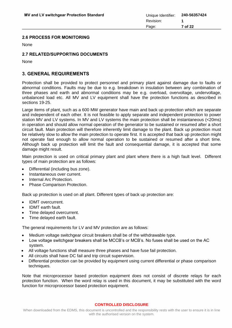
2.6 PROCESS FOR MONITORING
None
2.7 RELATED/SUPPORTING DOCUMENTS
None
3. GENERAL REQUIREMENTS
Protection shall be provided to protect personnel and primary plant against damage due to faults or abnormal conditions. Faults may be due to e.g. breakdown in insulation between any combination of three phases and earth and abnormal conditions may be e.g. overload, overvoltage, undervoltage, unbalanced load etc. All MV and LV equipment shall have the protection functions as described in sections 19-25.
Large items of plant, such as a 600 MW generator have main and back up protection which are separate and independent of each other. It is not feasible to apply separate and independent protection to power station MV and LV systems. In MV and LV systems the main protection shall be instantaneous (<20ms) in operation and should allow normal operation of the generator to be sustained or resumed after a short circuit fault. Main protection will therefore inherently limit damage to the plant. Back up protection must be relatively slow to allow the main protection to operate first. It is accepted that back up protection might not operate fast enough to allow normal operation to be sustained or resumed after a short time. Although back up protection will limit the fault and consequential damage, it is accepted that some damage might result.
Main protection is used on critical primary plant and plant where there is a high fault level. Different types of main protection are as follows:
Differential (including bus zone).
Instantaneous over current.
Internal Arc Protection.
Phase Comparison Protection.
Back up protection is used on all plant. Different types of back up protection are:
IDMT overcurrent.
IDMT earth fault.
Time delayed overcurrent.
Time delayed earth fault.
The general requirements for LV and MV protection are as follows:
Medium voltage switchgear circuit breakers shall be of the withdrawable type.
Low voltage switchgear breakers shall be MCCB’s or MCB’s. No fuses shall be used on the AC system.
All voltage functions shall measure three phases and have fuse fail protection.
All circuits shall have DC fail and trip circuit supervision.
Differential protection can be provided by equipment using current differential or phase comparison techniques.
Note that microprocessor based protection equipment does not consist of discrete relays for each protection function. When the word relay is used in this document, it may be substituted with the word function for microprocessor based protection equipment.

CONTROLLED DISCLOSURE
When downloaded from the EDMS, this document is uncontrolled and the responsibility rests with the user to ensure it is in line with the authorised version on the system.
MV and LV switchgear Protection Standard
Unique Identifier: 240-56357424
Revision: 1
Page: 8 of 22
3.1 PROTECTION FUNCTIONS
A summary of the application of circuit protection functions is as shown in Appendix A
3.2 TRIPPING PRINCIPLES
Generally, Main protection is specific to a particular board, item of equipment or circuit. The protection shall trip that board or circuit only for a fault on that board or circuit. Back-up protection is achieved by means of current or time grading.
One trip coil and one close coil per circuit shall be installed for each MV circuit. Trip circuit supervision and close circuit supervision shall be provided. Trip counters and running hour meters shall be installed for each MV circuit. These shall be functions forming part of the protection relay.
Differential protection, where applied, shall always overlap with other differential protection so that no part of the system is unprotected.
3.3 SETTING PRINCIPLES
Protection settings shall be such that protection equipment will only operate when required. This is to ensure maximum availability of generating units while providing adequate protection against faults and abnormal conditions.
Alternative (adaptive) setting ranges can be considered if primary plant conditions can change.
3.3.1 IDMT Overcurrent Settings
The longest protection time shall be within the rating of power equipment of the lowest rated device on the circuit. From a grading perspective, ratings of power equipment might change depending on their location in the power circuit (higher ratings closer to point of supply, lower downstream).
No power equipment shall be rated lower than 300 ms.
Pickup level shall be set to 1.05 x In of lowest power device capability in the circuit. Normal inverse curves shall be used except in exceptional circumstances.
The extreme downstream circuit shall be set to 50 ms and the grading margin shall be 250 ms.
3.3.2 Definite Time Overcurrent Settings
Normally this setting shall be 2 x full load current for all circuits except motors. For motors, this setting shall normally be 1.1 x peak starting current for 0.95 to 1.05 Vn.
All settings shall be less than 0.5 x lowest anticipated / prospective fault level. The pre-fault voltage levels shall be considered when calculating protection settings. The effect of motors starting shall be considered when calculating protection settings.
3.3.3 IDMT Earth Fault Settings
This is used on systems with an effective (solid) earth point. The pickup level shall be set to < 0.5 x lowest anticipated fault level. Normal inverse curves shall be used except in exceptional circumstances. The extreme downstream circuit shall be set to 50 ms and the grading margin shall be 250 ms.

CONTROLLED DISCLOSURE
When downloaded from the EDMS, this document is uncontrolled and the responsibility rests with the user to ensure it is in line with the authorised version on the system.
MV and LV switchgear Protection Standard
Unique Identifier: 240-56357424
Revision: 1
Page: 9 of 22
3.3.4 Definite Time Earth Fault Settings
This is used on systems with a non effective (resistance) earth point. The pickup level shall be set to < 0.5 x lowest anticipated fault level. The extreme downstream circuit shall be set to 50 ms and the grading margin shall be 250 ms.
3.4 INSTRUMENT TRANSFORMERS
3.4.1 Current Transformers
Current transformers shall meet the requirements of SANS 60044-1 and shall be PX, PR or measuring class. For PX class CT’s the turns ratio, the secondary resistance and the knee point voltage at magnetising current smaller than 100 mA shall be stated on the switchgear schedules.
For PR class the current ratio, the accuracy class in %, the accuracy limit factor and the burden in VA shall be stated on the switchgear schedules. For Measuring class CT’s the current ratio, the accuracy class in %, and the burden in VA shall be stated on the switchgear schedules.
Standard primary current values are 10 A, 12.5 A, 15 A, 20 A, 25 A, 30 A, 50 A, 60 A, 75 A or any multiple or fraction thereof (preferred values are underlined).
The current transformers shall also meet the following requirements:
Standard Secondary Current value is 1 A.
Standard VA ratings are 2.5, 5, 10, 15 and 30 VA.
Standard ALF ratings are 5, 10, 15, 20 and 30.
Differential protection circuits shall use class PX or 5PR.
Protection circuits shall use class 5PR or 10 PR.
Measuring circuits shall use class 0.1, 0.2, 0.5, 1, 3 or 5.
CT’s shall be located on the supply or load side of the circuit breaker.
Differential circuits shall have CT overlap.
CT’s shall be protection or measuring class.
3.4.2 Voltage Transformers
Voltage transformers shall meet the requirements of SANS 60044-2. For measuring class the Voltage Ratio, the Accuracy in % and the Burden in VA shall be stated on the switchgear schedules.
For protection class the Voltage Ratio, the Accuracy in %, the Burden in VA and the Voltage Factor shall be stated on the switchgear schedules.
The voltage transformers shall also meet the following requirements:
Standard Primary Voltages are as stated in IEC60038.
Standard Secondary Voltage value is 110 V.
Standard Accuracy for measuring VT’s is 0.1, 0.2, 0.5, 1.0 and 3.0.
Standard Accuracy for protection VT’s are 3P and 5P.
Standard VA ratings are 10, 15, 25, 30, 50, 75, 100, 150, 200, 300, 400 and 500.
Standard Voltage Factor: 1.2 continuous or 1.2 continuous and 1.5 for 30 s
or 1.2 continuous and 1.9 for 30 s
or 1.2 continuous and 1.9 for 8 hours.
Location: Cable or busbar.

CONTROLLED DISCLOSURE
When downloaded from the EDMS, this document is uncontrolled and the responsibility rests with the user to ensure it is in line with the authorised version on the system.
MV and LV switchgear Protection Standard
Unique Identifier: 240-56357424
Revision: 1
Page: 10 of 22
Connection: Delta-star, consideration shall be given to ferro-resonance, earthing, damping and fuses.
3.5 AUXILIARY DC SUPPLIES
3.5.1 Clean and Dirty Supplies
Clean supplies shall be provided for electronic equipment and dirty supplies shall be provided for motors and lighting. These may be from the same source if there is suitable filtering for the clean supply.
3.5.2 Redundancy
Single supplies shall be taken to panels and boards that require DC supplies. Dual supplies with a chop-over system at the panel or board shall not be provided.
3.5.3 Allowable Voltage Range
The standard voltage for protection equipment shall be 220 V DC. All protection equipment shall be capable of operating between minus 20% (176 V) and plus 20% (264 V) of the nominal voltage.
3.5.4 Standby Time
The standby time for the DC system shall be four hours.
3.5.5 Fuses and MCB’s
MCB’s are preferred to fuses on DC systems.
3.5.6 Earth Fault Protection/Detection
Earth fault protection is provided by MCB’s. Earth fault detection is provided by core balance type systems located at strategic points on the DC system.
3.6 MAIN AND BACK-UP GRADING
3.6.1 Current Grading
Current grading is achieved by Inverse Definite Minimum Time (IDMT) overcurrent relays. The relay operating time is inversely proportional to the magnitude of current. Relays at the end of a radial system shall operate quickly. A short time delay ensures stability. Relays upstream of the end circuits shall operate with a progressively longer time for a fault at the end circuits (they will operate faster for a fault upstream because of the higher fault current). The time delay depends on the number of circuit-breakers away from the end circuit. Relay and CT errors determine the time delay between circuit-breakers. For microprocessor based relays this time delay shall be 0.25 seconds.
In switchgear, IDMT overcurrent protection is back-up protection for downstream circuits. This protection is current and time graded to allow the downstream protection time to operate first.
Typical settings are as follows:
IDMT overcurrent pick up = 1.2 full load current.
Time delay = 0.25 s longer than the trip time of the next downstream circuit-breaker.

CONTROLLED DISCLOSURE
When downloaded from the EDMS, this document is uncontrolled and the responsibility rests with the user to ensure it is in line with the authorised version on the system.
MV and LV switchgear Protection Standard
Unique Identifier: 240-56357424
Revision: 1
Page: 11 of 22
3.6.2 Time Grading
The power station uses high resistance earthing on the MV systems to limit earth fault current. Current grading cannot be used in this case because the fault current level is similar throughout the system and all earth fault relays will operate at the same time for an earth fault downstream. Time grading is achieved with timers set at definite times. These time delays shall be less than 0.5 seconds longer than the next downstream protection.
LV protection is achieved by means of MCCB’s and MCB’s. Incoming cables to LV boards have high set definite time overcurrent protection for busbar protection. It is sometimes necessary to time delay this overcurrent protection trip. This is to allow MCB’s downstream of the incoming cable to operate first if a fault occurs. This time delay, if applicable, shall be less than 0.5 seconds.
In switchgear, earth fault protection is back-up protection for downstream circuits.
On solidly earthed systems, this protection is current graded to allow the downstream protection time to operate first.
On resistance earthed systems, this protection is time graded to allow the downstream protection time to operate first.
Typical settings for solidly earthed systems are:
IDMT Overcurrent pick-up = 0.1 to 0.4 full load current.
Time delay = 0.2 s to 0.3 s longer than the time of the downstream circuit-breaker. Typical settings for resistance earthed systems are:
Overcurrent pick up = 0.1 to 0.4 fault current.
Time delay = 0.2 s to 0.5 s longer than the time of the downstream circuit-breaker.
High set Overcurrent = 2 x fault current (this is to protect in the case of resistor flashover).
3.7 FUSES VERSUS CIRCUIT BREAKERS
Fuses and fused contactors shall not be used on the AC system.
3.8 RELAYING TECHNOLOGIES
The same standard hardware shall be used on all circuits as far as possible. Each relay shall have an integrated LCD display mimic with local keypad control. PC access shall be provided with integrated mimic and control from the PC. Remote access with integrated mimic and control shall be possible via the DCS.
Multi level password protection shall be provided. Level 3 is access to information only, level 2 is access to information and controls and level 1 is access to information, controls, configuration and settings.
3.9 COMMUNICATION TECHNOLOGIES
Equipment shall be compatible with IEC 61850 and the communication bus type shall be approved by Eskom. Equipment shall have GPS and time synchronization communication capability.
All MV switchgear shall be provided with an Intelligent Electronic Device (IED) that can provide the protection, control, monitoring, indication and communication functions. The device should be mounted in a control panel at eye-level for operation personnel access. This device should also have a Human Machine Interface (HMI) for display purposes. Light Emitting Diodes (LED) could also be installed on the relay to provide an indication function. The device should have a number of communication ports to allow for access to information via a personal computer (PC) and via the communication network.

CONTROLLED DISCLOSURE
When downloaded from the EDMS, this document is uncontrolled and the responsibility rests with the user to ensure it is in line with the authorised version on the system.
MV and LV switchgear Protection Standard
Unique Identifier: 240-56357424
Revision: 1
Page: 12 of 22
Multi level password protection shall be provided. Level 3 is access to information only, level 2 is access to information and controls and level 1 is access to information, controls, configuration and settings.
3.10 HARDWARE INTEGRATION AND CONFIGURATION
Relay integration and configuration shall be done by the Contractor in conjunction with Eskom.
3.11 SYNCHRONISING AND CHOP-OVER REQUIREMENTS
A bright chop-over is a chop-over operation where the closing breaker from the new supply is closed before the closed breaker from the old supply is opened. The two supplies are in parallel for a fraction of a second. The parallel operation time is minimised by tripping the closed breaker via an auxiliary contact of the closing breaker. A bright chop-over operation shall be interlocked with synchronising check function.
A dark chop-over is a chop-over operation where the closed breaker from the old supply is opened before the closing breaker from the new supply is closed. The equipment being supplied will have no power for a dead time. The dead time must be longer than 3 seconds.
Diesels are fitted with automatic synchronizers to enable bright chop overs to restore normal supplies. A diesel chop over is initiated automatically when:
Diesel is running and any one supply is restored.
A restored supply is confirmed when all three phase voltages > 95% for one second.
Diesel is running and any one supply is restored.
A restored supply is confirmed when all three phase voltages > 95% for one second.
3.12 EARTHING
On systems where the system capacitance is large, resistance earthing is required to stabilise the arcing earth faults and also to minimize damage to expensive equipment. This shall be applied on the unit auxiliary MV systems. The resistor rating shall be longer than the allowed tripping times and shall be at least 10 seconds. The earth fault current shall be limited to 350A.
Resistor protection shall be provided. An instantaneous overcurrent relay for resistor flashover is required. This shall be set at 2 x the anticipated / prospective fault level with resistor in circuit. A temperature sensor is required to provide an alarm.
Solid earthing shall be used on systems where the system capacitance is not large. This shall be applied on the Common Plant MV systems and the Unit and Common Plant LV systems.
3.13 SWITCHGEAR PROTECTION
3.13.1 Busbar Protection
This protection shall be provided on boards that have a high fault level (> 10 kA). Installation of this protection is also dependent on switchgear plant design parameters, configuration and type tests.
3.13.1.1 Bus Zone Differential
This is unit type protection, instantaneous in operation, covering the busbars for phase-to-phase faults. Bus zone protection shall be provided for all the unit boards.

CONTROLLED DISCLOSURE
When downloaded from the EDMS, this document is uncontrolled and the responsibility rests with the user to ensure it is in line with the authorised version on the system.
MV and LV switchgear Protection Standard
Unique Identifier: 240-56357424
Revision: 1
Page: 13 of 22
High impedance or low impedance differential protection may be used. High impedance is preferred for its simplicity. Each circuit on the board has a bus zone CT with the same turns-ratio (usually 1/2000). Bus zone CT supervision shall be provided to ensure that maloperation of the bus zone differential does not occur if a bus zone CT wire becomes loose.
Typical settings are:
Bus zone differential = 0.1 to 0.4 full load current.
Overcurrent check = 1.5 ( full load current + starting current of largest motor ).
3.13.1.2 Phase Comparison Differential
This shall be preferred to current differential schemes as the quantity of relays and CT’s is reduced.
3.13.1.3 Arc Detection Protection
This is unit type protection, instantaneous in operation, covering the breaker, busbar and cable compartments for arcing due to flashovers. Arc detection protection shall be provided for all the unit and common plant boards
Light sensitive detectors are placed in the switchgear. If a flashover occurs in the panel, the circuit breaker in the panel is tripped as well as the upstream circuit breaker feeding that panel. If a flashover occurs in the outgoing cable compartment of a fused contactor circuit, the arc detection delays the protection trip to give the fuse time to rupture. Several detectors can be connected to one protection scheme to provide partial or total busbar protection as required. Each arc detection protection scheme shall have an overcurrent and/or earth fault protection check interlock to prevent inadvertent operation.
Typical settings are:
Overcurrent check = 1.5 x ( full load current + starting current of largest motor).
Earth fault check = 0.2 x fault current.
Circuit breaker fail = 0.10 seconds.
3.13.1.4 Instantaneous Overcurrent
This is a relatively inexpensive way to provide busbar protection. This is used on the LV board incomers where the fault current is high. If there are large MCB’s on the board it may be necessary to grade with the MCB’s.
Typical settings are:
Instantaneous overcurrent = 1.5 x (full load current + starting current of largest motor ).
Time delay = 0.5 seconds.
3.14 CABLE PROTECTION
3.14.1 Pilot Wire Differential
This protection shall be provided on cables that have a high fault level (> 10 kA) and/or cables that are important to the operation of the station. It shall be provided on cables which connect boards that have bus zone protection. This is a unit type protection, instantaneous in operation, covering the cables for phase-to-phase faults. High impedance or low impedance differential protection may be used. High impedance is preferred for its simplicity. Each end of the protected cable has a protection scheme. These are connected by pilot wires which complete the differential circuit of the CT’s. Pilot wire differential protection overlaps at each end with bus zone protection if applicable.

CONTROLLED DISCLOSURE
When downloaded from the EDMS, this document is uncontrolled and the responsibility rests with the user to ensure it is in line with the authorised version on the system.
MV and LV switchgear Protection Standard
Unique Identifier: 240-56357424
Revision: 1
Page: 14 of 22
3.14.2 Phase Comparison Differential
If this is available from the supplier it shall be offered as the preferred alternative to Pilot Wire Differential.
3.14.3 Overcurrent
On pilot wire protected cables, IDMT overcurrent protection is the back-up protection for itself and for the downstream circuit. This protection is current graded to allow the downstream protection time to operate first.
On cables without pilot wire protection, IDMT overcurrent protection is the main protection for itself and back-up protection for downstream circuits. This protection is current graded to allow the downstream protection time to operate first.
Typical settings are:
IDMT overcurrent pick up = 1.2 full load current.
Time delay = 0.25 s longer than the trip time of the downstream circuit-breaker.
3.14.4 Earth Fault
On cables, earth fault protection is the main protection for itself and back-up protection for downstream circuits.
On solidly earthed systems this protection is current graded to allow the downstream protection time to operate first. The earth sheath rating shall be considered.
On resistance earthed systems this protection is time graded to allow the downstream protection time to operate first.
Typical settings for solidly earthed systems are:
IDMT overcurrent pick up = 0.1 to 0.4 full load current.
Time delay = 0.2.s to 0.5 s longer than the trip time of the downstream circuit-breaker (provided that the earth sheath rating is not exceeded).
Typical settings for resistance earthed systems are:
Overcurrent pick up = 0.1 to 0.4 fault current.
Time delay = 0.2 s to 0.5 s longer than the trip time of the downstream circuit-breaker.
3.15 TRANSFORMER PROTECTION
3.15.1 Transformer Differential
This protection shall be provided on transformers larger than 5MVA. This is a unit type protection, instantaneous in operation, covering the transformers for phase-to-phase faults. Transformer differential protection has second and fifth harmonic restraint to prevent inadvertent operation due to current inrush when energised. Transformer differential protection shall overlap with other differential protection if applicable.
Typical settings are:
Transformer differential = 0.1 to 0.5 full load current.

CONTROLLED DISCLOSURE
When downloaded from the EDMS, this document is uncontrolled and the responsibility rests with the user to ensure it is in line with the authorised version on the system.
MV and LV switchgear Protection Standard
Unique Identifier: 240-56357424
Revision: 1
Page: 15 of 22
3.15.2 Overcurrent
This protection shall be provided on all transformers. On transformers, IDMT overcurrent protection is main protection for itself and back-up protection for downstream circuit. This protection is current graded to allow the downstream protection time to operate first. Some relays have a high fixed instantaneous function. This can be set to operate for a fault in the transformer by setting the pick-up higher than the fault level for a low-voltage side fault. This protection is co-ordinated with the transformer short time and continuous ratings.
Typical settings are:
IDMT overcurrent pick-up = 1.5 to 2.0 (full load current + starting current of largest motor).
Time delay = 0.25 s longer than the trip time of the downstream breaker.
Instantaneous overcurrent pick-up = 1.5 to 2.0 LV fault level.
3.15.3 Earth Fault
This protection shall be provided on all transformers. On solid earthed systems, IDMT protection is used. On resistive earthed systems, DT protection is used with instantaneous overcurrent for resistor flashover.
Typical settings are:
IDMT earth fault pick-up = 0.5 anticipated fault level.
Time delay = 0.25 s longer than the trip time of the downstream circuit breaker.
DT earth fault pick-up = 0.5 anticipated fault level.
Time delay = 0.25 s longer than the trip time of the downstream circuit breaker.
High set overcurrent = 2 x fault current (this is to protect in the case of resistor flashover).
3.15.4 Buchholz
This protection shall be provided on all oil filled transformers. The Buchholz relay is a hydraulic device installed in the pipe between the transformer tank and the conservator. It operates on the principle that internal faults in oil-immersed transformers are associated with the production of gas and/or a surge of oil.
The relay collects the oil vapour or gas in a vessel. This vessel is normally full of oil and is fitted with a top and bottom float. Each float can operate a micro switch. The sequential displacement of each of the floats, due to the presence of gas, closes the micro switch contacts to give an alarm and then trip. A second micro switch can be operated by a surge of oil from the transformer tank to the conservator.
3.15.5 Pressure Relief Device (PRD)
This protection shall be provided on oil filled transformers. The PRD operates on the principle that a severe fault within the transformer produces a sudden overpressure inside the transformer tank. The PRD is a mechanical device installed in the wall of the transformer tank. It contains a diaphragm which displaces under pressure. The PRD opens to relieve the pressure inside the tank and operates a micro switch trip facility.
3.15.6 Transformer Oil and Winding Temperature
Oil temperature and/or winding temperature monitoring devices shall be fitted on oil type transformers. High oil or winding temperature is a result of overloading, high ambient temperature or a failure in the cooling system. These devices can be thermocouples located in the oil, winding or core of the transformer.

CONTROLLED DISCLOSURE
When downloaded from the EDMS, this document is uncontrolled and the responsibility rests with the user to ensure it is in line with the authorised version on the system.
MV and LV switchgear Protection Standard
Unique Identifier: 240-56357424
Revision: 1
Page: 16 of 22
Typical settings are:
Oil temperature alarm = 85°C.
Oil temperature trip = 100°C.
Winding temperature alarm = 100°C.
Winding temperature trip = 120°C.
3.16 MV MOTOR PROTECTION
3.16.1 Motor Differential
This protection shall be provided on motors larger than 1 MW. This is unit type protection, instantaneous in operation, covering the motors for phase-to-phase faults.
Typical settings are:
Motor differential = 0.1 to 0.5 full load current.
3.16.2 Motor Protection Relay
MV motors shall have motor protection which has the following functions.
3.16.2.1 Thermal Overload
This protection shall be provided for all motors. The allowed starts per hour shall be obtained from the motor supplier. The thermal overload protection function monitors the currents flowing into the motor. Based on these currents, it models the temperature inside the motor. Some modern relays have other functions, such as the number of starts per hour and cooling time constant, associated with the thermal overload. If available, these should all be activated.
Typical settings are:
Thermal overload = 1.05 to 1.1 full load current.
Number of starts per hour = 2 or 3.
Cooling time constant = 4 to 20 heating time constant.
Starting time = 1.1 x measured starting time.
3.16.2.2 Undervoltage
Three phase undervoltage protection shall trip all motor feeder circuits if an undervoltage condition occurs. Fuse fail protection shall be provided. This is required to prevent re-energisation of motors while still running down (causing shaft line overstressing) and to prevent overloading and tripping of upstream circuits due to many motors starting simultaneously.
Typical settings are:
Undervoltage = 0.7 x nominal voltage.
Time delay = < 3.0 seconds.
3.16.2.3 Instantaneous Overcurrent
This protection shall be provided on all MV motors. On motors, overcurrent protection operates for phase-to-phase faults. This protection is set to operate instantaneously. It has to be set higher than the starting current of the motor under worst voltage conditions.
Typical settings are:

CONTROLLED DISCLOSURE
When downloaded from the EDMS, this document is uncontrolled and the responsibility rests with the user to ensure it is in line with the authorised version on the system.
MV and LV switchgear Protection Standard
Unique Identifier: 240-56357424
Revision: 1
Page: 17 of 22
Instantaneous overcurrent pick-up = 1.1 to 1.5 starting current.
3.16.2.4 Earth Fault
This protection shall be provided on all motors. This protection does not have to grade with anything but normally has a short time delay to prevent maloperation due to third harmonics during motor starting.
Typical settings for solidly earthed systems are:
IDMT current pick-up = 0.1 to 0.4 full load current.
Time multiplier = 0.1 to 0.2.
Typical settings for resistance earthed systems are:
Current pick-up = 0.1 to 0.4 fault current.
Time delay = 0.5 second.
3.16.2.5 Negative Phase Sequence or Unbalance
This protection shall be provided on all motors. The motor Negative Phase Sequence capability shall be provided by the motor supplier.
Negative phase sequence protection safeguards the motor rotor against overheating caused by the induced double frequency (100 Hz) currents when negative phase sequence currents are present in the stator. The negative phase protection has an inverse time characteristic as well as a definite time characteristic for single phasing.
Negative phase sequence currents result from asymmetrical faults or unbalanced system conditions. The worst and the most common cause of negative phase sequence is the disconnection of one phase (single phasing). Negative phase sequence protection on motors must be graded with the generator negative phase sequence protection.
Typical settings are:
I2 IDMT current pick up = 0.1 to 0.2 full load current.
Time multiplier = 0.1 to 0.5.
Single phasing time = 1.0 second.
3.16.2.6 Stall Protection
Stall protection consists of an overcurrent protection element set below the locked rotor current and a time delay set to the stall capability time of the motor. Some large fan motors have a start time longer than the stall capability time. It is not possible to set the stall protection adequately in these cases.
Typical settings are:
Current pick-up = 0.9 locked rotor current.
Time delay = stall capability time of the motor.
3.17 EARTHING RESISTOR PROTECTION
3.17.1 Oil Temperature
Oil temperature monitoring devices shall be fitted on oil-filled resistors. High oil temperature is a result of a sustained earth fault, circulating third harmonic current or high ambient temperature. Where applications apply, high set earth fault can be used to protect the resistor from flashing.
Typical settings are:

CONTROLLED DISCLOSURE
When downloaded from the EDMS, this document is uncontrolled and the responsibility rests with the user to ensure it is in line with the authorised version on the system.
MV and LV switchgear Protection Standard
Unique Identifier: 240-56357424
Revision: 1
Page: 18 of 22
Oil temperature alarm = 85°C.
Oil temperature trip = 100°C.
High set overcurrent = 2 x fault current (this is to protect in the case of a flashover on the resistor).
3.18 LV SWITCHGEAR PROTECTION
3.18.1 Overcurrent
Incoming cables to LV boards shall have high fixed overcurrent protection for busbar protection. It is sometimes necessary to time delay the overcurrent protection trip to allow grading with breakers downstream of the incoming cable if a fault occurs.
Typical settings are:
Current pick-up = 1.5 to 2.0 full load current.
Time delay = 0.5 seconds.
3.18.2 Fuses
No fuses shall be used on the AC system. Fuses are the preferred option for the DC system.
3.18.3 Moulded Case Breaker
All circuits on main LV boards shall be protected by MCCB’s. This is necessary because fault levels are generally high on LV boards.
Moulded case-breakers are used on sub-distribution boards for socket outlets and lighting. Earth leakage protection shall be provided on socket outlet circuits and welding plugs.
3.19 LV MOTOR PROTECTION
3.19.1 Motor Protection Relay
Important or critical LV motors shall have protection similar to that required for MV motors.
3.19.1.1 Overcurrent
LV motors shall have MCCB’s or MCB’s with instantaneous overcurrent and thermal overload function to provide protection against phase to phase and phase to earth faults.
3.19.1.2 Thermal Overload
LV motors not fitted with motor protection shall have thermal overload devices incorporated in the breaker to trip for a sustained overload condition.
Typical settings are:
Thermal overload = 1.05 full load current.
3.19.1.3 Undervoltage
Three phase undervoltage protection is required to trip all motor feeder circuits if an undervoltage condition occurs. Fuse fail protection shall be provided. This is required to prevent re-energisation of

CONTROLLED DISCLOSURE
When downloaded from the EDMS, this document is uncontrolled and the responsibility rests with the user to ensure it is in line with the authorised version on the system.
MV and LV switchgear Protection Standard
Unique Identifier: 240-56357424
Revision: 1
Page: 19 of 22
motors while still running down and causing shaft line overstressing. It is also required to prevent overloading and tripping of upstream circuits due to many motors starting simultaneously.
Typical settings are:
Undervoltage = 0.7 x nominal voltage.
Time delay = < 3.0 seconds.
3.19.1.4 Instantaneous Overcurrent
This protection shall be provided on all LV motors. On motors, overcurrent protection operates for phase-to-phase faults. This protection is set to operate instantaneously. It has to be set higher than the starting current of the motor under worst voltage conditions.
Typical settings are:
Instantaneous overcurrent pick-up = 1.1 to 1.5 starting current.
3.19.1.5 Earth Fault
This protection shall be provided on all LV motors. This protection does not have to grade with anything but normally has a short time delay to prevent maloperation due to third harmonics during motor start.
3.19.1.6 Negative Phase Sequence or Unbalance
This protection shall be provided on all LV motors. The motor Negative Phase Sequence capability shall be provided by the motor supplier.
Negative phase sequence protection safeguards the motor rotor against overheating caused by the induced double frequency (100 Hz) currents when negative phase sequence currents are present in the stator. The negative phase protection has an inverse time characteristic as well as a definite time characteristic for single phasing.
Negative phase sequence currents result from asymmetrical faults or unbalanced system conditions. The worst and the most common cause of negative phase sequence is the disconnection of one phase (single phasing). Negative phase sequence protection on motors must be graded with the generator negative phase sequence protection.
Typical settings are:
I2 IDMT current pick up = 0.1 to 0.2 full load current.
Time multiplier = 0.1 to 0.5.
Single phasing time = 1.0 second.
3.19.1.7 Stall Protection
Stall protection consists of an overcurrent protection element set below the locked rotor current and a time delay set to the stall capability time of the motor. Some large motors have a start time longer than the stall capability time. It is not possible to set the stall protection adequately in these cases.
Typical settings are:
Current pick-up = 0.9 locked rotor current.
Time delay = stall capability time of the motor.
4. AUTHORISATION
This document has been seen and accepted by:

CONTROLLED DISCLOSURE
When downloaded from the EDMS, this document is uncontrolled and the responsibility rests with the user to ensure it is in line with the authorised version on the system.
MV and LV switchgear Protection Standard
Unique Identifier: 240-56357424
Revision: 1
Page: 20 of 22
Name & Surname Designation
Document Approved byTDAC ROD 16 July 2013
5. REVISIONS
Date Rev. Compiler Remarks
November 2012 0.1 P.I. Heera Senior Electrical Engineer
Draft document for Review created from 474-0810
December 2012 1 P.I. Heera Senior Electrical Engineer
Final Document Authorised for Publication
6. DEVELOPMENT TEAM The following people were involved in the development of this document:
None
7. ACKNOWLEDGEMENTS
None

CONTROLLED DISCLOSURE
When downloaded from the EDMS, this document is uncontrolled and the responsibility rests with the user to ensure it is in line with the authorised version on the system.
MV and LV switchgear Protection Standard
Unique Identifier: 240-56357424
Revision: 1
Page: 21 of 22
APPENDIX A: SUMMARY OF PROTECTION FUNCTION REQUIREMENTS
Description IDMT O/C INST O/C E/F or SE/F
DIFF U/V Motor protection
Thermal O/L
MCCB’s or MCB’s
field inputs
Note 1 2 4 3
MV incomer - x x x - - - - -
MV Bus section - - - - - - - - -
LV incomer - x x - - - - - -
MV transformer 5 x x x x - - - - x
MV transformer x x x - - - - - x
MV motor 5 - x x x x x - - x
MV motor - x x - x x - - x
LV motor 5 - - x - x x - x -
LV motor - - - - - - x x -
MV cable 5 x - x x - - - - -
MV cable x - x - - - - - -
LV cable - - - - - - - x -
Notes:
1 Instantaneous overcurrent is used on dedicated circuits and for bus zone and internal arc
interlocking.
2 Differential protection installed on incomers is the one side of pilot wire or transformer differential
protection
3 Thermistor type heat detectors are installed in MV motors but at present are not used for protection.
4 The use of MCCB’s or MCB’s in this application depends on the system fault level and circuit load.
5 Critical and high fault level plant.

CONTROLLED DISCLOSURE
When downloaded from the EDMS, this document is uncontrolled and the responsibility rests with the user to ensure it is in line with the authorised version on the system.
MV and LV switchgear Protection Standard
Unique Identifier: 240-56357424
Revision: 1
Page: 22 of 22
DOCUMENT CHANGES PAGE
Page no. Description of change Requested by