STANDARD SPECIFICATIONS & DETAILS For … specifications & details . for . water & sewer...
139
STANDARD SPECIFICATIONS & DETAILS For WATER & SEWER CONSTRUCTION CITY OF NORTH MYRTLE BEACH HORRY COUNTY, SOUTH CAROLINA Public Water System No. 2610011 Ocean Drive WWTP NPDES SC0022152 Crescent Beach WWTP NPDES SC0022161 NPDES MS4 Stormwater Discharge Permit SCR035106 Kevin D. Blayton, PE City Engineer July 2007
Transcript of STANDARD SPECIFICATIONS & DETAILS For … specifications & details . for . water & sewer...

STANDARD SPECIFICATIONS & DETAILS
For
WATER & SEWER CONSTRUCTION
CITY OF NORTH MYRTLE BEACH HORRY COUNTY, SOUTH CAROLINA
Public Water System No. 2610011
Ocean Drive WWTP NPDES SC0022152 Crescent Beach WWTP NPDES SC0022161
NPDES MS4 Stormwater Discharge Permit SCR035106
Kevin D. Blayton, PE City Engineer
July 2007

TABLE OF CONTENTS
GENERAL REQUIREMENTS Pages SECTION 00800 GENERAL REQUIREMENTS 1-7 SECTION 00900 SPECIAL PROVISION SPECIFICATIONS DIRECTIONAL DRILLING (13000) 1-5 POLYETHYLENE PIPE FOR DRILLING (13010) 1-3 DETAILED SPECIFICATIONS SECTION 02000 SITE CLEARING 1-2 SECTION 02100 EXCAVATION 1-4 SECTION 02200 BACKFILLING 1-5 SECTION 02300 TRENCHING 1-3 SECTION 02400 ASPHALT PAVEMENT AND BASE 1-6 SECTION 02410 PATCHING ASPHALT PAVEMENT 1-6 SECTION 02420 CONCRETE SIDEWALK, CURB & GUTTER 1-3 ROADWAY STANDARD DETAIL DRAWINGS R1 – R24 SECTION 02500 STORM DRAINAGE SYSTEMS 1-8 SECTION 02525 PRECAST DRAINAGE STRUCTURES 1-11 STORM DRAINAGE & EROSION CONTROL
STANDARD DETAIL DRAWINGS SD1–SD19 SECTION 02600 SANITARY SEWER GRAVITY SYSTEMS 1-10
SEWER STANDARD DETAIL DRAWINGS S1-S19
SECTION 02625 SEWER FORCE MAIN SYSTEMS 1-20 SECTION 02650 SEWER PUMPING STATIONS 1-6 PUMP STATION STANDARD DETAIL DRAWINGS PS1-PS12
July 2007 TOC - 1
July 2007 TOC - 2
TABLE OF CONTENTS SECTION 02700 WATER DISTRIBUTION SYSTEMS 1-16 WATER STANDARD DETAIL DRAWINGS W1-W27 SECTION 02800 EROSION CONTROL, SEEDING, & SODDING 1-7 SECTION 03250 CAST IN PLACE CONCRETE 1-5 SECTION 03260 FLOWABLE FILL 1-3 SECTION 03300 CONCRETE CURING 1-2 SECTION 03500 PRECAST CONCRETE STRUCTURES 1-8

SECTION 00800
GENERAL REQUIREMENTS 1.1 PLANS & SPECIFICATIONS: The Contractor shall maintain a set of approved plans
and specifications on the job site at all times. 1.2 EXISTING SITE CONDITIONS: The Contractor acknowledges that he has
thoroughly investigated the existing conditions and has examined the plans and specifications, understanding clearly their requirements and the requirements necessary to construct the improvements contracted for; that he is fully prepared to sustain all losses and damages incurred by the actions of elements; is prepared to provide all necessary tools, appliances, machinery, skilled and unskilled workmen, and all necessary materials to successfully complete the work. The Contractor shall be responsible for providing and disposing of all materials.
1.3 SITE DRAINAGE: The Contractor is hereby made aware that some areas of the site
may not be well drained and it shall be the responsibility of the Contractor to provide positive drainage on the site during construction. Temporary drainage ditches, swales or piping required for this purpose must be approved by the Engineer before construction and must be constructed so as not to interfere with other work activities and shall comply as much as possible with the concept of the master drainage plan for the project.
A. Grade site to drain. Maintain excavations free of water. Provide, operate, and
maintain pumping equipment.
B. Protect site from ponding or running water. Provide devices as required to protect site from soil erosion.
1.4 ENVIRONMENTAL REGULATIONS: The Contractor shall be responsible for
insuring that his forces comply with environmental regulations on site. Should construction forces violate laws, ordinances or regulations causing delays or adverse consequences on the site, the Contractor shall be held responsible for said actions.
1.5 STATE HIGHWAY ENCROACHMENT: The Owner has obtained encroachment
agreements for all work located in the public rights-of-way as required. The Contractor shall be responsible for complying with all provisions of the encroachment permit. A copy of the permit will be provided to the Contractor.
1.6 TRAFFIC SAFETY & CONTROL: The Contractor shall provide adequate warning
signs, and where necessary, flagmen to control traffic flow and movement at construction locations. Where public streets are affected, traffic will be maintained on such public streets at all construction locations and no public street or road shall be blocked completely at any time. The paved areas of all public roads and streets shall be sufficiently cleared each night and during other nonworking hours to assure safe, two-way traffic. Construction equipment such as excavation machines, loaders, tractors, trucks, pumps, etc., shall be removed from public traffic lanes and paved areas so as to provide a safe area for traffic. Excavations adjacent to roadways shall not be left open
July 2007 00800-1
overnight. 1.7 UTILITY LOCATION & CONFLICTS: Telephone lines, power lines, cables, and
other utilities may be encountered and should be anticipated. The Contractor shall contact representatives of all utilities to determine the exact locations of all existing facilities and underground utilities and shall make every effort to avoid damage to such. Exploratory hand excavation prior to machine excavation should be done to avoid damage to existing facilities. Any existing utilities damaged by the Contractor shall be repaired or replaced by the Contractor at his own expense.
1.8 SECURITY & SAFETY: The Contractor shall provide security and adequate barriers to
protect the Work, existing facilities, and the Owner's operations from unauthorized entry, vandalism, theft or damage from construction operations.
A. Provide barriers to prevent unauthorized entry to construction areas and to protect
existing facilities and adjacent properties from damage from construction operations.
B. Provide barricades and walkways required by governing authorities for public
right-of-ways.
C. Provide suitable barriers and such warning lights as will effectively prevent the occurrence of any accident to health, limb, or property.
D. Lights shall be maintained between the hours of sunset and sunrise.
E. Provide protection for plant life designated to remain. Replace damaged plant
life.
F. Protect non-owned vehicular traffic, stored materials, site and structures from damage.
1.9 RESTROOM FACILITIES: Temporary restroom facilities shall be provided for
employee use. Facilities must be cleaned regularly and may not remain on the job site after the job has been completed.
1.10 WORK SCHEDULE: The Contractor shall furnish the Engineer a job schedule
showing the various components of work and the anticipated beginning and completion date for each particular phase of the project. Work may not begin until all permits are issued for the project, including but not limited to: SCDHEC-Water and Sewer Construction Permit, SCDHEC/OCRM-Land Disturbance, SCDOT-Highway Encroachment, City of North Myrtle Beach-Grading Permit
1.11 PROJECT SUPERVISION: The Contractor shall provide a full time superintendent at
the job site acceptable to the Engineer who shall have full authority to act for the Contractor. The Superintendent shall be fully responsible to maintain the activities of any and all subcontractors on the job, and to respond to job instructions from the Engineer and Owner.
July 2007 00800-2

1.12 SUBCONTRACTORS: In the interest of assuring the most expeditious and properly controlled project, unless specifically approved in writing, it is a condition of this contract that the Prime Bidder must accomplish not less than 50% of the work to be done with his own forces. This shall in no way prohibit the use of rental equipment by the Prime Contractor's forces. All equipment and personnel shall be subject to approval of the Engineer.
1.13 PRECONSTRUCTION CONFERENCE: The Engineer will schedule a pre-
construction conference. The Owner, Engineer, Project Manager and Inspector, and Contractor or his representative shall attend. The following issues will be discussed:
1. Distribution of approved Plans & Specifications, Permits, and
Encroachments 2. Submission of shop drawings and other submittal data regarding materials,
methods of construction, etc. 3. Designation of personnel representing the Contractor, Engineer, and
Owner 4. Procedures and processing of field decisions, submittals, and substitutions 5. Project schedule
1.14 CONSTRUCTION STAKE OUT & FIELD ENGINEERING:
A. The Owner shall furnish vertical and horizontal control points, as may be Necessary.
B. The Contractor shall give the Owner reasonable notice (72 hour minimum) of his requirements for survey lines and grades.
C. The contractor shall provide field-engineering services; establish elevations, lines,
and levels utilizing recognized engineering survey practices. 1.15 SHOP DRAWING & MATERIAL SUBMITTALS:
A. Transmit submittals to the Engineer for approval with adequate space for Engineer review stamps. The number of copies submitted shall equal the number required for the Contractor and Subs, plus two copies for the Engineer.
B. Identify Project, Contractor, Subcontractor, or Supplier, pertinent drawing sheet
and detail number(s), and specification section number, as appropriate. Indicate material or product conforms to or exceeds specified requirements. Clearly mark each submittal to identify applicable products, models, options, and other data. Submit supporting reference data, affidavits, and certifications as appropriate.
C. No partial submittals acceptable. Provide certification with submittals stating that
all equipment proposed is in complete accordance with the Contract Documents without exception. Shop drawings will not be reviewed without this certification attached and if submitted without this certification will be returned, disapproved.
D. Revise and resubmit submittals as required, identify all changes made since
previous submittal.
July 2007 00800-3

E. When specified in individual specification Sections, submit manufacturers' printed instructions for delivery, storage, assembly, installation, start-up, adjusting, and finishing, in quantities specified for Product Data.
F. When specified in individual specification Sections, submit manufacturer's
certificate to Engineer for review, in quantities specified for Product Data. 1.16 PRODUCT OPTIONS:
A. Products specified by reference standards or by description only: Any product meeting those standards or description.
B. Products specified by naming one or more manufacturers: Products of
manufacturers named and meeting specifications, no options or substitutions allowed.
C. Products specified by naming one or more manufacturers with a provision for
substitutions: Submit a request for substitution for any manufacturer not named. 1.17 PRODUCT SUBSTITUTIONS:
A. Substitutions may be considered when a Product becomes unavailable through no
fault of the Contractor.
B. Document each request with complete data substantiating compliance of proposed substitution with contract documents.
C. A request constitutes a representation that the Contractor:
1. Has investigated proposed product and determined that it meets or exceeds
the quality level of the specified product. 2. Will provide the same warranty for the substitution as for the specified
product. 3. Will coordinate installation and make changes to other work which may
be required.
D. Substitutions will not be considered when they are indicated or implied on shop drawing or product data submittals, without separate written request, or when acceptance will require revision to the contract documents.
E. Substitution submittal procedure:
1. Submit three copies of request for substitution for consideration. Limit
each request to one proposed substitution. 2. Submit shop drawings, product data, and certified test results attesting to
the proposed product equivalence. 3. The Engineer will notify Contractor, in writing, of decision to accept or
reject request.
July 2007 00800-4

1.18 MATERIAL HANDLING, STORAGE, & PROTECTION:
A. Products: Only new materials and equipment shall be supplied and installed as part of the Work. Do not reuse materials removed from existing premises, except as specifically permitted by the Owner.
B. Transportation and handling: The Contractor shall handle Products in accordance
with manufacturer's instructions.
1. Promptly inspect shipments to assure that Products comply with requirements, quantities are correct, and Products are undamaged.
2. Provide equipment and personnel to handle Products by methods to prevent soiling, disfigurement, or damage.
C. Storage and protection: The Contractor shall store and protect Products in
accordance with manufacturer's instructions, with seals and labels intact and legible. Store sensitive Products in weather-tight, climate-controlled enclosures.
1. For exterior storage of fabricated Products, place on sloped supports,
above ground. 2. Provide off-site storage and protection when site does not permit on-site
storage or protection. 3. Cover Products subject to deterioration with impervious sheet covering.
Provide ventilation to avoid condensation. 4. Store loose granular materials on solid flat surfaces in a well-drained area.
Prevent mixing with foreign matter. 5. Provide equipment and personnel to store Products by methods to prevent
soiling, disfigurement, or damage. 6. Arrange storage of Products to permit access for inspection. Periodically
inspect to assure Products are undamaged and are maintained under specified conditions.
1.19 QUALITY ASSURANCE & QUALITY CONTROL: The Contractor shall:
A. Monitor quality control over suppliers, manufacturers, Products, services, site conditions and workmanship to produce Work of specified quality.
B. Comply fully with manufacturers' instructions, including each step in sequence. C. Should manufacturers' instructions conflict with Contract Documents, request
clarification from Engineer before proceeding.
D. Comply with specified standards as a minimum quality for the Work except when more stringent tolerances, codes, or specified requirements indicate higher standards or more precise workmanship.
E. Perform work by persons qualified to produce workmanship or specified quality.
F. Secure Products in place with positive anchorage devices designed and sized to
July 2007 00800-5

withstand stresses, vibration, physical distortion or disfigurement. 1.20 INSPECTION & TESTING:
A. The Owner will appoint and pay for the services of an independent firm to provide inspection and testing services. The independent testing firm will perform inspections, tests, and other services as stated in the specifications or as required by the Engineer.
B. Reports will be submitted by the independent firm to the Engineer, in duplicate,
indicating observations and results of tests and indicating compliance or non-compliance with Contract Documents.
B. The Contractor shall provide access and coordinate the services of the testing firm
and shall:
1. Notify Engineer and independent firm 24 hours prior to expected time for operations that require testing services.
2. Furnish samples of materials, design mix, equipment, tools, storage and assistance as requested.
3. Make arrangements with independent firm and pay for additional samples and tests required for Contractor's use.
D. Retesting required where initial tests reveal non-conformance to specified
requirements shall be performed by the same independent firm on instructions by the Engineer and paid for by the Contractor.
1.21 PROJECT CLOSEOUT:
A. Cleaning Up: The contractor shall at all times keep the premises free from accumulations of waste materials or rubbish from and about the project as well as all his tools, construction equipment, machinery and surplus materials.
C. Project Record Documents: The General Contractor shall maintain at the site for
the Owner, one copy of all drawings, specifications, addenda, approved shop drawings, change orders and other modifications in good order and marked as "as built copy" to record all changes made during construction by all contractors. These shall be available to the Engineer. The drawings marked to record all changes made during construction shall be delivered to him for the Owner upon completion of the work.
C. Operations & Maintenance Manuals: The Contractor shall provide all O+M
manuals, spare parts, etc. as specified in the Detailed Specifications. 1.22 RECORD DRAWINGS (AS-BUILTS): The Contractor shall keep a complete record
of variations between the contract drawings and the actual project installation. One set of drawings shall be marked in red by the Contractor showing such variations and delivered to the Engineer upon completion of the project.
July 2007 00800-6

July 2007 00800-7
A. Store Record Documents separate from documents used for construction.
B. Record information concurrent with construction progress.
C. The Contractor shall locate all water meters, valves, manholes, sewer taps, etc. by measurement from two (2) property pins in addition to providing the following:
1. Measured depths of foundations in relation to finish elevation. 2. Measured horizontal and vertical locations of underground utilities and
appurtenances, referenced to permanent surface improvements. 3. Measured locations of internal utilities and appurtenances concealed in
construction, referenced to visible and accessible feature of the Work. 4. Field changes of dimension and detail. 5. Details not on original Contract Drawings.
1.23 GUARANTEE: The Contractor shall furnish a written guarantee that all work executed
under the plans and specifications will be free from defects of materials and workmanship for a period of one (1) year from the date of final acceptance and that all defects occurring within that period shall be replaced at no cost to the Owner. Where guarantees or warranties are written in any section for a period of more than one year, such longer terms shall apply. The Contractor shall, in case of work performed by his subcontractors and where guarantees are required, be responsible for warranty of all subcontractors’ work.
END OF SECTION
SECTION 00900
SPECIAL PROVISION SPECIFICATIONS 1. The Contractor is solely responsible for safety in the project areas and shall be responsible
for the erection and maintenance of barricades and other safety control measures. During the construction period, the work area shall be secured and adequate warning notices to the public must be erected to ensure the safety of the travelling public.
2. The Contractor will be allowed to close one lane of traffic during construction as shown on
the traffic control plan. The Contractor shall erect such barricades and provide other traffic control measures, such as flagmen, as may be necessary for traffic control.
3. The City has received Encroachment Permits from the SC DOT for the work outlined on the
Drawings. Copies of the Encroachment Permits are Included in the section of the Contract Documents. The Contractor is responsible for complying with the requirements shown on the SC DOT encroachment Permits for this project.
4. The Contractor shall use all reasonable means to notify property owners that will be
impacted by the construction activities. This includes but shall not be limited to, notifying property owners when their driveway will be blocked and notifying them when landscaping will have to be removed or relocated.
5. Weekend work restrictions shall be in effect in accordance with the attached memo from
SCDOT. 6. Specifications for directional drilling polyethylene pipe are included for use as specified on
the plans.
July 2007 00900-1

July 2007 13000-1
DIRECTIONAL DRILLED WATER & SEWER
GENERAL
1.01 Section Includes
A. Installation of underground pipelines by directionally controlled horizontal drilling
1.02 Related Sections
A. Section 02000 - Site Clearing B. Section 02625 – Sewer Force Main Systems
C. Section 02700 - Water Distribution Systems
D. Section 13010 - Polyethylene Pipe
1.03 References
A. ASTM D 1248 polyethylene plastics molding and extrusion materials.
B. ASTM D 2774 recommended practice for underground installation of thermoplastic pressure piping.
1.04 Submittals
A. Submit specifications for the directional boring machine and related equipment to be used.
B. Submit documentation showing the following minimum experience:
1. Two recently completed projects of comparable size and length.
2. Two years of continuous experience in the drilling field.
C. Bentonite slurry to be used.
PRODUCTS 2.01 Casing Pipe - Contractor shall supply all casing pipe according to the following specifications:
A. Section 13010 - Polyethylene Pipe 2.02 Temporary Workspace and Access

July 2007 13000-2
Workspace and access shall be through an existing utility easement as shown on the plans. Any additional workspace required shall be the contractor’s responsibility. The contractor shall coordinate his activities with the Owner.
2.03 Permits The Owner shall be responsible for obtaining all SCDHEC, OCRM and SCDOT permits
(as required). The contractor must obey all applicable regulations specified by the aforementioned regulatory agencies.
2.04 Bentonite
Bentonite shall conform to API Specification 13A and have the capacity of mixing with water to form a stable and homogenous suspension.
2.05 Drilling Water
The owner will provide water required for drilling and hydrostatic testing. Contractor is responsible for transporting and storing needed quantities of any water required. Contractor shall coordinate his water requirements with the owner.
2.06 Excess Drilling Fluid Disposal
Excess drilling fluid must be disposed of at an approved site. The Contractor shall describe in writing the disposal location to the engineer. Disposal of drilling fluids must meet all federal and state standards. Contractor is responsible for transporting all excess fluids to the disposal site and paying any disposal costs.
2.07 Inadvertent Drilling Fluid Return
Contractor shall immediately clean up all locations where drilling fluid inadvertently surfaces.
2.08 Concern for Other Underground Utilities
A. Contractor’s operations may be conducted in a location, which contains other underground utilities. The Contractor shall contact Palmetto Utility Location Service at 1-800-922-0983, seventy-two (72) hours (three (3) days) before beginning any work in this area.
B. Verify the location of all adjacent underground utilities. The locations of other utilities are drawn on the plans in their approximate location for informational purposes only. This shall include exposing any utilities, which are located within 30 feet of the designed drilled path, to get an accurate depth measurement.
C. Modify drilling practices or downhole assemblies to prevent damage to adjacent
underground utilities.
D. Any existing utilities, structures, monuments, etc. damaged by the Contractor

July 2007 13000-3
shall be repaired or replaced by the Contractor at his own expense. 2.09 Carrier Pipe
Carrier pipe shall be manufactured of HDPE in accordance with specification Section 13010. Pipe shall be installed with either wood skids and stainless steel bands or prefabricated casing spacers. Skids shall be made of pretreated timber and spacers shall be Cascade Waterwork Mfg. Co. Or approved equal. Maximum spacing between supports shall be six (6) feet.
EXECUTION 3.01 Description A. The Work to be performed under this contract shall consist of the installation of the lines
shown on the construction plans by the directionally controlled horizontal drilling method. Services furnished by the contractor shall be performed in accordance with the best industry practice and these contract documents and shall include all labor, equipment and items necessary to accomplish the following tasks:
1. Supply of all pipe as required for the installation in accordance with the
specification Section 13010.
2. Clearing, grading and general site/access preparation necessary for construction operations. These services will be performed in accordance with specification Sections 2100, 2200 and 2300.
3. Transportation of all equipment, labor, and items to and from the jobsite.
4. Erection of horizontal drilling equipment at the rig site defined in construction
drawings.
5. Drilling of a pilot hole along the alignment defined in construction drawings.
6. Reaming the pilot hole to a diameter suitable for installation of the prefabricated pull section.
7. Installation of the prefabricated pull section along the reamed hole.
8. Prefabrication of the pull section in accordance with specification Section 13010.
9. Hydrostatic testing the installed segment in accordance with specification Section
2700. 10. Erosion control, clean up and restoration of all work areas in accordance with
specification Section 2800.
July 2007 13000-4
3.02 Instrumentation
The Contractor will at all times provide and maintain instrumentation which will accurately locate the pilot hole and measure drilling fluid flow discharge rate and pressure. The Engineer will have access to these instruments and their readings at all times.
3.03 Pilot Hole
A. Directional Tolerance - The pilot hole shall be drilled along the path shown on the
construction drawings to the following tolerances:
1. Elevation - Plus 1 foot, minus 1 foot. A minimum 0.80% slope will be required at all times
. 2. Horizontal Alignment - Plus or Minus three (3) feet.
3. Entry Point Location - The pilot hole shall initially penetrate the ground
surface at the exact location shown on the construction drawings.
4. Exit Point Location - The pilot hole shall finally penetrate the ground surface within plus or minus three (3) feet of the alignment shown in the construction drawings.
5. See construction drawings for further allowable tolerances.
B. As-Built Survey - At the completion of pilot hole drilling, Contractor shall
provide a tabulation of coordinates references to the drilled entry point, which accurately describe the location of the pilot hole. This survey will be reviewed by the Engineer before reaming operations shall begin.
3.04 Ream & Pull Back
A. Pre-reaming - Pre-reaming operations shall be conducted at the discretion of the
horizontal drilling contractor. All provisions of this specification relating to simultaneous reaming and pulling back operations shall also pertain to pre-reaming operations.
B. Pulling Loads - The maximum allowable tensile load imposed on the pipeline pull
section shall be equal to 90% of the product of the SMYS of the pipe and the area of steel in the pipe section. If more than one value is involved for a given pull section, the lesser shall govern.
C. Torsional Stress - A swivel shall be used to connect the pipeline pull section to
the reaming assembly to minimize torsional stress imposed on the section.
D. Pull Section Support - The pull section shall be supported as it proceeds during pull back so that it moves freely.

July 2007 13000-5
E. Hydrostatic Pretest - The entire pull section shall be subjected to a four hour hydrostatic test with zero leakage prior to being installed in the hole. The test pressure shall be equal to or exceed that required for final certification. See Section 2700 for further details.
F. Pull Section Length - If space allows, the pull section shall be installed in one
continuous length with no tie-in welds. If space is not available, tie-in welds shall be minimized and fully inspected by radiographic means prior to installation.
3.05 Drilling Fluids
A. Composition - The composition of all drilling fluids used shall be submitted to the Engineer for approval prior to utilization. No fluid will be approved or utilized that does not comply with permit requirements and environmental regulations.
B. Disposal - Disposal of drilling fluids shall be the responsibility of the Contractor
and shall be conducted in compliance with all pertinent environmental regulations, right-of-way and workspace agreements and permit requirements. Disposal of drilling fluids within proposed area shall not be allowed.
C. Inadvertent Returns - Drilling fluid returns at locations other than the entry and
exit points shall be minimized. Contractor shall immediately clean up any inadvertent returns.
D. Drilling efforts and recirculation when required across the proposed project shall
not be conducted with the use of temporary piping or hoses.
END OF SECTION
July 2007 13010-1
SECTION 13010
POLYETHYLENE PIPE FOR DRILLING GENERAL 1.01 DESCRIPTION
Work entails waterline piping necessary to directionally drilled crossing including material specification, production, storage and handling, and installation.
1.02 RELATED SECTIONS A. Section 13000 - Directional Drilled Crossing PRODUCTS 2.01 MATERIAL SPECIFICATIONS A. All polyethylene pipe furnished under these specifications shall conform to all applicable
requirements in the latest revision of the following standards, unless other wise specified herein:
1. ASTM D-1248 Specification for Polyethylene Molding and Extrusion Materials. 2. ASTM D-3350 Polyethylene Plastics (PE) Pipe and Fittings Materials 3. ASTM D-1693 Environmental Stress-Cracking of Ethylene Plastics. 4. ASTM 2321-74 Underground Installation of Flexible Thermoplastic Sewer Pipe. 5. ASTM F-714 Polyethylene Plastic Pipe (SDR-PR) Based on Outside Diameter.
6. AWWA C 906 Polyethylene (PE) Pressure Pipe and Fittings 4" through 63" for Water Distribution.
2.02 MATERIAL AND WORKMANSHIP A. The piping material and fittings shall meet the requirements of Type III, Class C,
Category 5, Grade P34 polyethylene material as defined in ASTM D-1248, shall be identified by the cell classification system of ASTM D-3350 as PE 345434C and have the Plastic Pipe Institute (PPI) designation of PE3408. All pipe shall be American Made meeting the AWWA C 906 Specifications.
B. All pipe shall be DIP (Ductile Iron Pipe Size) unless otherwise noted on the plans.

July 2007 13010-2
C. The Owner may request certified lab data to verify the physical properties of pipe or may take random samples and have them tested by an independent testing laboratory.
D. Design/Pressure Class: Pressure class (PC) ratings for pipe covered by this standard are
given. The following expression, commonly known as the ISO (International Organization for Standardization) equation, is used to calculate the pressure class rating:
PC = { 2 ÷ (DR - 1) } x HDB x DF
Where: PC = Pressure class, in psig HDB = Hydrostatic design basis, in psi...1,600 psi @ 73ΕF for PE 3408 DR = Dimensoin ratio, ratio of the specified average outside diameter to the
minimum specified wall thickness, both expressed in the same units DF = Design factor; includes consideration of degree of safety and all the
variables, included limited surge pressure effects, in the end application...(normally “0.5" representing the industry accepted 2:1 safety factor)
In no case shall PE pipe with a pressure class less than DR 17 be used.
E. Workmanship shall be of the highest level compatible with current commercial practice.
The polyethylene pipe shall be homogeneous throughout and be free of visible cracks, holes, foreign inclusions or other injurious defects. It shall be uniform in color, opacity, density and other physical properties.
F. The manufacturer shall have adequate equipment and quality control facilities to
continually result in a finished product that will have the properties indicated herein. The manufacturer shall be a current member of the Plastic Pipe Institute.
2.03 REJECTION
Polyethylene pipe and fittings may be rejected for failure to meet any of the requirements of this specification.
EXECUTION 3.01 HANDLING AND INSTALLATION
Pipe shall be stored on clean level ground to prevent undue scratching or gouging. Sections of pipe with deep cuts or gouges (>10%) shall be removed and the ends of the pipe rejoined. Handling of the joined pipe shall be in such a manner that the pipe is not damaged by dragging over sharp edges or cutting objects.
3.02 JOINING
Sections of the polyethylene pipe shall be joined into continuous lengths by the butt fusion method and shall be performed by factory certified technician in strict

conformance with the pipe manufacturers recommendations using approved equipment. 3.03 BURIAL
The trench and trench bottom, embedment materials and bedding and installation practices shall be as specified in ASTM 2321-74, Sections 6, 7, 8, and 9.
END OF SECTION
July 2007 13010-3
SECTION 02000
SITE CLEARING GENERAL 1.01 SECTION INCLUDES
A. Removal of surface debris.
B. Clear site of plant life and grass.
C. Remove trees and shrubs.
D. Remove root system of trees and shrubs.
E. Topsoil excavation. 1.02 REGULATORY REQUIREMENTS
A. Conform to applicable codes for disposal of debris.
B. Coordinate clearing work with Owner. C. Clearing shall not begin until the SWPPP has been approved and permit coverage
has been issued. PRODUCTS Not Used EXECUTION 3.01 PREPARATION A. Verify that existing plant life and features designated to remain are identified and
protected. 3.02 PROTECTION
A. Locate, identify, and protect existing utilities from damage.
B. Protect benchmarks and existing structures from damage or displacement.
C. Protect trees, plant growth and features outside of designated construction limits.
July 2007 02000-1

July 2007 02000-2
3.03 CLEARING
A. Clear areas required for access to the site and performance of the work. B. Remove all vegetation and organic material from earthwork (excavation, fill, etc.)
area. Remove trees, shrubs, stumps, root mat, root system and surface rock to a depth of 24 inches.
3.04 REMOVAL & DISPOSAL
A. The Contractor shall remove all cleared debris, rock, plant matter, and other unsalvageable materials from site and dispose of at an approved landfill.
3.05 TOPSOIL EXCAVATION
A. Excavate topsoil from entire site.
B. Stockpile in area designated on site to a height not exceeding 8 feet.
END OF SECTION

SECTION 02100
EXCAVATION GENERAL 1.01 SECTION INCLUDES A. Grading and excavation for roadway and drives.
B. Grading and excavation for pipelines and channels.
C. All excavation, formation of embankments and finishing and dressing of graded earth areas, shoulders and ditches.
1.02 RELATED SECTIONS
A. Section 00800 – General Requirements
B. Section 02200 - Backfilling
C. Section 02300 - Trenching 1.03 FIELD MEASUREMENT
A. Verify that survey benchmark and intended elevations for the work are as indicated.
PRODUCTS Not Used EXECUTION 3.01 GENERAL
A. The term "excavation" used hereinafter is defined as "unclassified excavation". Excavation of every description regardless of material encountered within the grading limits of the project, shall be performed to the lines and grades indicated. Satisfactory excavated material shall be transported to and placed in the fill areas within the limits of the work. When directed by the Engineer, unsatisfactory material encountered within the limits of the work shall be excavated below the grade shown and replaced with satisfactory material as directed in order to obtain the required surface condition and density to sustain the subsequent work. Such material ordered as a replacement shall be paid for at the unit prices given in the stated allowance shown in the proposal. The Contractor shall dispose of excavated
July 2007 02100-1

material, which is not suitable for use as fill, at an approved landfill. During construction, excavation and filling shall be performed in a manner and sequence that will provide drainage at all times. Except where otherwise shown on the plans or as directed, the unsatisfactory soils shall be removed to a depth required and filled with selected sands and sand clays from borrow excavations that will provide a firm, unyielding sub-grade at the specified density.
B. All areas covered by the project, including excavated and filled sections and
adjacent transition areas, shall be uniformly graded. The finished surface shall be reasonably smooth, compacted and free from irregular surface changes. The degree of finish shall be that ordinarily obtainable from grader or scraper operations. The finished surface shall be not more than 0.10 foot above or below the established grade or approved cross section. Gutters and ditches shall be finished so as to permit adequate drainage.
C. All vegetation, roots, brush, sod, broken pavements, rubbish and other
unsatisfactory or surplus material stripped or removed from the limits of construction shall be hauled off the Owner's property and disposed of by the Contractor at an approved landfill.
D. The Contractor shall be responsible for control of erosion and sedimentation
during the work. Silt screens, hay bales or other devices as required shall be installed to prevent off-site deposits of eroded materials. Similar devices shall be placed around storm drain catch basins and inlets to prevent the infiltration of soil materials into the underground drainage system. Such devices shall be maintained until all site work is complete and a satisfactory stand of grass has been established as approved by the Engineer.
3.02 CONSERVATION OF TOPSOIL
A. Areas designated for grading operations that contain a blanket of soil which is more satisfactory for the growth of grass than the embankment material to be placed, as determined by the Engineer, shall be stripped to a depth of approximately four to six inches and placed in convenient stockpiles as directed in the field, for later use as a topsoil blanket on the new graded areas specified herein, or as designated.
B. Material ordered stockpiled shall be placed in a satisfactory manner to afford
drainage.
C. When grading operations permit, instead of stockpiling, the topsoil shall be hauled and spread directly on the areas to receive topsoil.
D. Surplus topsoil shall remain the property of the Contractor.
3.03 PROTECTION OF EXISTING SERVICE LINES, UTILITIES & STRUCTURES
A. Existing utility lines and structures that are shown on the drawings or the locations or other utility lines which may exist in the project area, as well as
July 2007 02100-2
utility lines constructed during excavation operations, shall be protected from damage during excavation, and if damaged, shall be repaired by the Contractor at his expense.
B. When utility lines that are to be removed or relocated are encountered within the
area of operations, the Contractor shall notify the utility company in ample time for the necessary measures to be taken to prevent interruption of the service.
C. It shall be the Contractor's responsibility to contact all utility companies with
services in the area for an accurate location of the respective utilities prior to beginning excavation.
3.04 EXCAVATION OF DITCHES
A. Ditches shall be cut accurately to the cross sections and grades indicated by the drawings.
B. All roots, stumps and other foreign matter in the sides and bottom of ditches shall
be cut 18 inches below the grades indicated.
C. Any excessive ditch excavation due to the removal of roots, stumps, etc., or due to over-excavation, shall be backfilled to grade either with satisfactory soils thoroughly compacted, or with suitable stone, as directed by the Engineer.
D. The Contractor shall maintain all ditches excavated under this specification free
from detrimental quantities of leaves, sticks and other debris until final acceptance of the work.
E. Satisfactory earth material excavated from ditches and channel changes shall be
placed in fill areas as directed.
F. All excess excavation and debris shall be disposed of off-site unless otherwise directed by the Engineer.
G. Berming of soils along the ditch bank will not be permitted.
H. No excavated material shall be deposited within a distance of three feet from the
edge of any ditches. I. The Contractor shall be responsible for maintaining these newly constructed
ditches and take immediate action to keep erosion of the ditch bottom and slopes to a minimum during the life of the contract.
3.05 PREPARATION
A. Identify required lines, levels, contours and datum.
B. Identify and mark known underground, above ground and aerial utilities.
July 2007 02100-3

July 2007 02100-4
C. Protect above and below grade utilities which are to remain.
D. Protect plant life, lawns and other features remaining as a portion of final landscaping.
E. Protect benchmarks, existing structures, fences, sidewalks, paving and curbs from
excavation equipment and vehicular traffic. 3.06 EXCAVATION
A. Underpin adjacent structures, which may be damaged by excavation work, including utilities and pipe chases.
B. Excavate subsoil required to accommodate building foundations, slabs-on-grade,
paving and site structures.
C. Grade top perimeter of excavation to prevent surface water from draining into excavation.
D. Hand trim excavation. Remove loose matter.
E. Remove lumped subsoil, boulders and rock up to 1/3 cubic yard measured by
volume.
F. The Contractor shall notify the Engineer of unexpected subsurface conditions and discontinue affected work in area until notified to resume work.
G. Correct unauthorized excavation.
H. Stockpile excess excavated material not being used in an area.
3.07 FIELD QUALITY CONTROL
A. Coordinate and provide access for visual inspection, compaction testing, proof rolling, etc. of bearing surfaces.
3.08 PROTECTION
A. Protect excavations to prevent cave-in or loose soil from falling into excavation.
END OF SECTION

SECTION 02200
BACKFILLING GENERAL 1.01 SECTION INCLUDES
A. Structure backfilling to sub-grade elevations.
B. Site filling and backfilling.
C. Fill and compaction of trenches.
D. Consolidation and compaction.
E. Fill for over-excavation. 1.02 RELATED SECTIONS
A. Section 02100 - Excavation.
B. Section 02300 - Trenching. 1.03 REFERENCES
A. ASTM C 136 - Sieve Analysis of Fine and Coarse Aggregates.
B. ASTM D 1556 - Standard Test Method for Density of Soil in Place by the Sand-Cone Method.
C. ASTM D 1557 - Standard Test Methods for Moisture-Density Relations of Soils
and Soil-Aggregate Mixtures using a 10-lb Rammer and 18-in. Drop.
D. ASTM D 2922 - Standard Test Methods for Density of Soil and Soil-Aggregate in Place by Nuclear Methods.
PRODUCTS 2.01 FILL MATERIALS
A. Type A (Class 1) - Coarse Stone Crushed: Angular, washed natural stone; free of shale, clay, friable material, sand, debris; graded in accordance with ASTM C 136 within the following limits:
July 2007 02200-1

Sieve Size Percent Passing 2 inches 100 1 inch 95 3/4 inch 95 to 100 5/8 inch 75 to 100 3/8 inch 55 to 85 No. 4 35 to 60 No. 16 15 to 35 No. 40 10 to 25 No. 200 5 to 10
B. Type B (Class 2) - Pea Gravel: Natural stone; washed, free of clay, shale, organic matter; graded in accordance with ASTM C 136, to the following:
1. Minimum Size: 1/4 inch
2. Maximum Size: 5/8 inch
C. Type C (Class 3) - Sand: Natural river or bank sand; washed, free of silt, clay, loam, friable or soluble materials or organic matter; graded in accordance with ASTM C 136, within the following limits:
Sieve Size Percent Passing No. 4 100 No. 14 10 to 100 No. 50 5 to 90 No. 100 4 to 30 No. 200 0
D. Acceptable Native Material: Reused and/or imported, free of gravel larger than 3-inch size, roots and other organic material and trash and approved by the Engineer.
EXECUTION 3.01 EXAMINATION
A. The Contractor shall verify that fill materials to be reused are approved by the Engineer.
3.02 PREPARATION
A. Generally, compact sub-grade to density requirements for subsequent backfill materials.
B. Cut out soft areas of any sub-grade that is not capable of compaction. The
Contractor shall place Type C backfill and compact to a density equal to or
July 2007 02200-2

greater than requirements for any subsequent backfill material. C. Prior to placement of aggregate base coarse material at gravel or paved areas,
compact sub-grade to a minimum of 98% of its maximum dry density in accordance with ASTM D 1557 and AASHTO T-180.
D. All vegetation, such as roots, brush, heavy sods, heavy growth of grass and all
decayed vegetable matter, rubbish and other unsuitable material within the area upon which fill is to be placed shall be stripped or otherwise removed before the fill is started.
E. In no case will unstable material remain in or under the fill area that will prevent
the placement and compaction of subsequent layers to the specified densities.
F. Sloped ground surfaces steeper than one vertical to four horizontal on which fill is to be placed shall be plowed, stepped and benched, or broken up as directed, in such manner that the fill material will bond with the existing surface.
G. Prepared surfaces on which compacted fill are to be placed shall be scarified,
wetted or dried as may be required to obtain the compaction specified. 3.03 BACKFILLING
A. Backfill areas at the locations and to lines and elevations shown on the drawings.
B. Filled areas shall conform to the shape of the typical sections indicated or shall meet the requirements of the particular case.
C. Systematically backfill to allow maximum time for natural settlement. Do not
backfill over porous, wet, frozen or spongy sub-grade surfaces.
D. Granular Fill: Place and compact materials in continuous layers not exceeding 6 inches compacted depth.
E. Soil Fill: Place and compact material in continuous layers not exceeding 8 inches
compacted depth.
F. Employ a placement method that does not disturb or damage utilities in trenches.
G. Maintain optimum moisture content of backfill materials to attain required compaction density.
H. Slope grade away from structures at a minimum 2 inches in 10 ft., unless noted
otherwise.
I. Make grade changes gradual. Blend slope into level areas.
J. Stockpile surplus reusable backfill materials on Owner's property at Owner's designated site.
July 2007 02200-3
K. Leave fill material stockpile areas completely free of excess unsuitable materials. 3.04 TOLERANCES
A. Top Surface of Backfilling: Plus or minus one tenth from required elevations. 3.05 FIELD QUALITY CONTROL
A. The Engineer shall conduct field inspections with assistance from an independent testing lab.
B. Tests and analysis of fill material shall be performed in accordance with ASTM D
1557 (AASHTO T-180).
C. Compaction testing shall be performed in accordance with ASTM D 1557 (AASHTO T-180) and ASTM D 2922.
D. If tests indicate work does not meet specified requirements, remove work, replace
and retest at no additional cost to Owner.
E. Frequency of tests: As required by the testing firm or as directed by the Engineer.
F. Proof-roll all compacted fill surfaces under paving. 3.06 PROTECTION OF FINISHED WORK
A. Protect all finished Work.
B. Re-compact fills subjected to vehicular traffic. 3.07 COMPACTION REQUIREMENTS
A. The compaction of fill materials shall meet the following requirements as determined by the maximum density obtained at optimum moisture content by an approved laboratory.
1. Fill under structures 100% 2. Fill under paved areas 98%
3. Fill in other areas 95%
B. The Contractor shall be responsible for compaction of the existing soils to meet the above compaction requirements.
C. The Contractor will be responsible for compacting the sub-grade to the required
density by whatever means necessary. 3.08 SCHEDULE
A. Fill under grassed areas.
July 2007 02200-4

July 2007 02200-5
1. Subsoil fill with acceptable native material to finished grade.
B. Fill under asphalt concrete pavement.
1. Type C fill to 8 inches below finished paving elevation.
END OF SECTION
SECTION 02300
TRENCHING GENERAL 1.01 SECTION INCLUDES
A. Excavate trenches for utilities.
B. Compacted bedding under fill over utilities.
C. Backfilling and compaction. 1.02 RELATED SECTIONS
A. Section 02100 - Excavation.
B. Section 02200 - Backfilling.
C. Section 02600 - Sanitary Sewer Gravity Systems.
D. Section 02625 - Sewer Force Main System.
E. Section 02700 - Water Distribution Systems. 1.03 FIELD MEASUREMENTS
A. Verify that survey benchmark and intended elevations for the Work are as shown on the drawings prior to proceeding with construction.
PRODUCTS 2.01 FILL MATERIALS
A. Types A, B, and C subsoil materials as specified in Section 02200.
B. Reuse native materials as approved by the Engineer. 2.02 BEDDING MATERIALS
A. Type 1 Material: As specified for Type A in Section 02200.
B. Type 2 Material: As specified for Type B in Section 02200.
C. Type 3 Material: As specified for Type C in Section 02200.
July 2007 02300-1

D. Acceptable Native Material: As specified in Section 02200. EXECUTION 3.01 EXAMINATION
A. The Contractor shall verify that fill materials to be reused are approved by the Engineer.
3.02 PREPARATION
A. Identify required lines, levels, contours, and datum.
B. Protect plant life, lawns, rock outcropping and other features remaining as a portion of final landscaping.
C. Protect benchmarks, existing structures, fences, sidewalks, paving and curbs from
excavation equipment and vehicular traffic.
D. Protect existing above and below grade utilities which are to remain.
E. The Contractor shall cut out soft areas of the sub-grade that are not suitable for compaction and backfill with Type 3 fill and compact to density equal to or greater than the requirements for any subsequent backfill material.
3.03 EXCAVATION
A. Excavate existing sub-grade required for storm sewer, sanitary sewer, or water line piping.
B. Cut trenches sufficiently wide as shown in the standard details to enable
installation of utilities and allow inspection.
C. Hand trim for bell and spigot pipe joints. Remove loose material.
D. Remove lumped subsoil, boulders and rock larger than 3 inches in diameter.
E. Correct unauthorized excavation at no cost to Owner.
F. Correct areas over-excavated by error in accordance with Section 02200.
G. Stockpile excess excavated material, suitable for use as fill, at an approved location. Excess excavated material unsuitable for use as fill shall be removed from the site and disposed of by the Contractor.
3.04 BEDDING
A. Support pipe during placement and compaction of bedding fill.
July 2007 02300-2

July 2007 02300-3
3.05 BACKFILLING
A. Backfill trenches to elevations shown on plans.
B. Systematically backfill work areas to allow maximum time for maximum compaction. Do not backfill over porous, wet, frozen or spongy sub-grade surfaces.
C. Granular Fill: Place and compact material in continuous layers not exceeding 6
inches compacted depth. D. Soil Fill: Place and compact material in continuous layers not exceeding 8 inches
compacted depth.
E. Employ a placement method that does not disturb or damage foundation perimeter, pipe, or conduit in trench.
F. Maintain optimum moisture content of backfill materials to attain required
compaction density.
G. Leave fill material stockpile areas completely free of excess unsuitable materials. 3.06 TOLERANCES
A. Top Surface of Backfilling: Plus or minus one tenth from required elevations. 3.07 FIELD QUALITY CONTROL
A. Field inspection shall be performed by an independent material testing firm approved by the Engineer.
3.08 PROTECTION OF FINISHED WORK
A. Protect all finished Work under provisions of Section 00500.
B. Re-compact fills subjected to vehicular traffic. 3.09 TRENCH SAFETY
The Contractor shall be responsible for proper shoring and/or sloping of the trench in compliance with applicable OSHA regulations.
END OF SECTION
SECTION 02400
ASPHALT PAVEMENT AND BASE GENERAL 1.01 SECTION INCLUDES
A. Hot Laid Asphalt Concrete Pavement.
B. Base Course Materials and Preparation.
C. Sub-grade Preparation. 1.02 RELATED SECTIONS
A. Section 02100 - Excavation.
B. Section 02200 - Backfilling. 1.03 REFERENCES
A. SCDOT Standard Specifications, 2000 Edition.
B. SCDOT Manual of Uniform Traffic Control Devices for Streets and Highways. 1.04 QUALITY ASSURANCE
A. Conform to SCDOT Standard Specifications except where more stringent requirements are specified herein.
B. Obtain materials from same source throughout.
1.05 TESTING REQUIREMENTS
A. Testing and analysis of asphalt mix will be performed under provisions of Section 01400 - Quality Control.
1.06 SUBMITTALS
A. Provide certification from all suppliers stating that materials supplied comply with all specifications.
B. Submit proposed mix design of each class of mix for review and approval prior to
commencement of work.
July 2007 02400-1

July 2007 02400-2
1.07 ENVIRONMENTAL REQUIREMENTS A. Apply bituminous prime and tack coats when the ambient temperature is above 40
degrees F., and when temperature has been above 35 degrees F for 12 hours immediately prior to application. Do not apply when base is wet or contains excess moisture.
B. Construct asphalt concrete paving only when atmospheric temperature is above 40
degrees F. PRODUCTS 2.01 PAVEMENT MATERIALS
A. Prime Coat: Medium, curing cutback asphalt, Type MC-30.
B. Tack Coat: Emulsified asphalt, Type SS-1.
C. Asphalt Cement: AASHTO M 226 (Table 2), Type AC-20.
D. Aggregate for Mix: SCDOT Type 3 2.02 ASPHALT PAVING MIX
A. Use dry materials to avoid foaming. Mix uniformly. B. Topping Course: 4.8 to 6.8 percent of asphalt cement by weight in mixture.
2.03 SAND ASPHALT LEVELING MIX
A. Mixture of fine aggregate and asphalt cement, properly mixed at an approved plant to meet the requirements of SCDOT Standard Specifications Section 309.
B. The aggregate in the mixture shall be composed of local sand or local sand
containing crushed shell, blends of sand and stone, slag or limestone screenings or other approved materials. The local sand shall be non-plastic, sharp, hard durable grain free from deleterious substances.
C. The constituents of the base course shall be combined in such proportions that,
after mixing, the resultant mixture will be homogeneous and all particles coated with asphalt cement.
2.04 STABILIZED AGGREGATE BASE COURSE
A. This work shall consist of a base course composed of coarse aggregate, together with fine aggregate or binder material and water, which shall be mixed, compacted, and primed when specified, all in accordance with the SCDOT Standard Specifications for Highway Construction, Section 306.

B. The aggregate in the base course shall consist of a mixture of either crushed stone, crushed slag, or crushed or uncrushed gravel, together with sand, sand-gravel, soil or other approved materials having similar characteristics, combined as necessary to give a mixture conforming to the SCDOT requirements.
C. The aggregate shall be free from lumps or balls of clay or other objectionable
matter.
D. The composite mixture of coarse aggregate and binder material shall meet the grading requirements specified for Types 1 or 2 after it has been mixed, laid down, and after initial compaction operations have begun. The composite mixture shall meet the requirements of SCDOT Standard Specifications for Highway Construction, Section 306.
2.05 OTHER BASE COURSE MATERIALS
A. Other base course materials may be used with the approval of the engineer. All materials must meet the requirements of the SCDOT Standard Specifications for highway construction.
EXECUTION 3.01 SUBGRADE PREPARATION
A. Prior to beginning paving work, inspect sub-grade for loose or soft material, rock or organic matter. No stones over 2" in diameter will be allowed in the top 6" of the sub-grade.
B. Proof roll cut sub-grade using loaded 20 ton dump truck or similar weight
construction equipment to verify that sub-grades are stable and to identify loose or soft areas requiring undercutting or stabilization.
C. Stabilization of soft or unstable sub-grades shall be accomplished to a minimum
depth of 12".
D. Verify elevations and cross sections of sub-grade immediately prior to placing base course material.
3.02 BASE COURSE PREPARATION
A. The base course shall be placed on the approved sub-grade and uniformly spread.
B. Shape base to provide thicknesses and widths as shown on the drawings. C. The base shall be consolidated by rolling until it is thoroughly bonded and
compacted.
July 2007 02400-3
3.03 APPLICATIONS
A. Prime Coat:
1. The prime coat shall not be applied until the base course has seasoned sufficiently to permit a uniform penetration. The base shall be dry when the prime is applied.
2. Apply prime coat to all base material surfaces where asphalt concrete
paving will be constructed.
3. Apply prime coat in accordance with SCDOT Standard Specifications at a rate of 0.1 gallons per square yard.
4. Apply at a uniform rate of 0.25 to 0.30 gallons per square yard over
compacted base material. Apply to penetrate and seal, but not flood surface.
5. Cure and dry as long as necessary to attain penetration and evaporation of
volatile.
B. Tack Coat:
1. Apply to contact surfaces of previously constructed asphalt concrete courses and surfaces abutting or projecting into asphalt concrete pavement.
2. Apply tack coat to contact surfaces of concrete curbing.
3. Apply tack coat at a rate of 0.1 gallons per square yard, in accordance with
SCDOT Standard Specifications.
4. Allow tack to dry until at proper condition to receive paving. 3.04 ASPHALTIC CONCRETE PLACEMENT
A. Place asphalt concrete mixture on completed compacted sub-grade surface, spread, and strike off.
B. The mixture shall be delivered to the spreader at a temperature between 250° F.
and 325° F. and within 20° F of the temperature set at the plant.
C. Place asphalt to achieve the compacted thickness identified on the drawings. 3.05 ROLLING AND COMPACTION
A. The mixture, after being spread, shall be thoroughly compacted by rolling as soon as it will bear the weight of the rollers without undue displacement. The number,
July 2007 02400-4

weight, and types of rollers and sequences of rolling operations shall be such that the required density and surface are consistently attained while the mixture is in a workable condition.
B. Compact mixture with hand tampers or vibrating plate compactors in areas
inaccessible to rollers.
C. Breakdown Rolling: After longitudinal joints and edges have been compacted, breakdown rolling should follow immediately.
D. Intermediate Rolling: Follow breakdown rolling as closely as possible, while the
asphalt mix is still well above the minimum temperature at which densification can be achieved. Intermediate rolling should be continuous until all of the mix placed has been thoroughly compacted.
E. Finish Rolling: Perform finish rolling while mix is still hot enough for removal of
roller marks.
F. Patching: Remove and replace defective areas. Cut out such areas and fill with fresh, hot asphalt concrete. Compact to maximum surface density and smoothness.
3.06 TOLERANCES
A. Compaction and Density Requirements:
1. Base and sub-grade: Compact sub-grade to 98% and base to 100% as measured by ASTM D 2922 and ASTM D 1557 (AASHTO T-180).
2. Asphalt Pavement: Minimum acceptable density of in place material shall
be 98% of recorded laboratory specimen density.
B. Allowable Variation in Thickness:
1. Base course: (+\-) 1/2". 2. Surface (wearing) course: (+\-) 1/8".
C. Surface Smoothness: Test finished surface of each asphalt course for smoothness
using a 10'-0" straight edge. Intervals of tests shall be as directed by the Engineer. Surfaces will not be acceptable if exceeding the following:
1. Base course: 1/2" in 10'-0". 2. Surface (wearing) course: 1/4" in 10'-0".
D. Laboratory shall test in place courses for compliance with specified density, thickness and surface smoothness. Engineer shall specify testing locations and number of tests.
E. Laboratory shall take two 4" diameter cores per 1,000 sq. yards of paved surface
(400 LF of roadway) at locations directed by the Engineer.
July 2007 02400-5
July 2007 02400-6
F. Contractor's duties relative to testing shall include:
1. Notifying laboratory of conditions requiring testing. 2. Coordinating with Engineer and laboratory for field testing. 3. Paying costs for retesting where initial tests reveal nonconformance with
specified requirements. 4. Repair holes resulting from coring to match existing surface.
3.07 FIELD QUALITY CONTROL
A. Field inspection and testing will be performed under provisions of Section 00800. 3.08 TRAFFIC CONTROL
A. Comply with State Manual of Uniform Traffic Devices for Streets and Highways.
B. Maintain vehicular and pedestrian traffic during paving operations as required for other construction activities.
C. Provide flagmen, barricades, warning signs and warning lights for movement of
traffic and safety and to cause the least interruption of work. 3.09 CLEANING AND PROTECTION
A. At completion of each operation, remove excess or spilled materials from site. Do not dump or spread excess asphalt materials on the project site.
B. After placement of surface course, no vehicular traffic shall be allowed on
pavement until it has cooled and hardened and in no case sooner than 12 hours.
END OF SECTION


July 2007 02420-1
SECTION 02420
CONCRETE SIDEWALK, CURB & GUTTER GENERAL 1.01 SECTION INCLUDES
A. Cast-in-place concrete sidewalk construction.
B. Cast-in-place concrete curb and gutter construction. 1.02 RELATED SECTIONS
A. Section 02100 - Excavation.
B. Section 02400 - Hot Laid Asphalt Concrete Pavement and Base.
C. Section 03250 - Concrete. 1.03 REFERENCES
A. ACI 347 - Recommended Practice for Concrete Form Work.
1.04 QUALITY ASSURANCE
A. Obtain materials from same source throughout. 1.05 ENVIRONMENTAL REQUIREMENTS
A. Do not place concrete in temperatures less than 40 degrees F without Engineer's approval.
PRODUCTS 2.01 MATERIALS
A. Concrete Materials: Comply with requirements of Section 03250 for concrete materials, curing materials and others as required.
B. Forms: Steel, wood, or other suitable material of size and strength to resist
movement during concrete placement and to retain horizontal and vertical alignment until removal. Use straight forms, free of distortion and defects. Use flexible spring steel forms or laminated boards to form radius bends as required. Coat forms with non-staining type coating that will not discolor or deface surface

of concrete.
C. Joint Fillers: Resilient pre-molded bituminous impregnated fiberboard units complying with ASTM D 1751, FS HH-F-341, Type II, Class A; or AASHTO M 153, Type I.
2.02 MIX DESIGN
A. Mix design shall comply with requirements of Section 03250.
B. Design mix to produce normal weight concrete consisting of portland cement, aggregate, water-reducing admixture, air-entraining admixture, and water to produce the following properties:
1. Compressive Strength: 3,000 psi, minimum at 28 days, unless otherwise
indicated on Plans.
2. Slump Range: 2" - 4" maximum.
3. Air Entrainment: 5% to 8%. EXECUTION 3.01 INSPECTION
A. Verify reinforcement and other items to be cast into concrete are accurately placed, held securely, and will not cause hardship in placing concrete.
3.02 PREPARATION
A. Form Construction
1. Set forms to the specified grades and lines, rigidly braced and secured.
2. Clean forms after each use, coat with form release agent as often as required to ensure separation from concrete without damage.
B. Concrete Placement
1. Do not place concrete until sub-grade and forms have been checked for
line, grade and compaction.
2. Place concrete using methods that prevent segregation of the mix.
3. Automatic machine may be used for curb and gutter placement at Contractor's option. Machine placement must produce curbs and gutters to required cross section, lines, grades, finish, and jointing as specified for formed concrete. If results are not acceptable, remove and replace with formed concrete as specified.
July 2007 02420-2

July 2007 02420-3
C. Joint Construction
1. Weakened Joints: Provide joints at intervals of 10 feet maximum each way. The joint shall be made by cutting the concrete with a trowel or by other acceptable methods.
2. Expansion Joints: Preformed expansion joints 3/4 or an inch thick,
extending the full depth of the concrete sidewalk or curbing, shall be constructed at all radius points, junctions with existing concrete, inlets and manholes, and at not more than 100 foot intervals in continuous runs of curb.
D. Place concrete continuously between predetermined expansion joints. Do not
break or interrupt successive pours such that cold joints occur.
E. Excessive honeycomb or embedded debris in concrete is not acceptable. Notify Engineer upon discovery.
3.03 FINISHING
A. Broom finish by drawing fine-hair broom across concrete surface parallel to line of traffic. Repeat procedure if required to provide fine line texture.
3.04 PATCHING
A. Notify Engineer immediately upon removal of forms.
B. Patch imperfections. 3.05 DEFECTIVE CONCRETE
A. Modify or replace concrete not conforming to required levels and lines, details and elevations.
B. Repair or replace concrete not properly placed or the specified type.
C. Remove and replace defective concrete as directed, at no additional cost to the
Owner. 3.06 FIELD QUALITY CONTROL
A. Field inspection and testing will be performed under provisions of Section 00800. 3.07 PROTECTION
A. Protect concrete from damage until acceptance of work. END OF SECTION

SECTION 02500
STORM DRAINAGE SYSTEMS GENERAL 1.01 SECTION INCLUDES
A. Storm drainage piping, fittings, and accessories.
B. Catch basins, junction boxes and drop inlets. 1.02 RELATED SECTIONS
A. Section 01500 - Construction Facilities and Temporary Controls
B. Section 02100 - Excavation
C. Section 02200 - Backfilling.
D. Section 02300 - Trenching.
E. Section 03250 - Concrete.
F. Section 03500 – Pre-cast Concrete Structures 1.03 REFERENCES - The publications listed below form a part of this specification to the extent referenced.
A. AASHTO M252 - 1990 ® 1992) Corrugated Polyethylene Drainage Tubing.
B. AASHTO M294 - 1990 (R1992) Corrugated Polyethylene Pipe, 12" to 36" Diameter.
C. ACPA 01-102 - 1998 Concrete Pipe Handbook.
D. ACPA 01-103 - 1990 Concrete Pipe Installation Manual.
E. ASTM A 497 - 1990 (Rev. B) Steel Welded Wire Fabric, Deformed, for Concrete
Reinforcement.
F. ASTM C 32 - 1991 Sewer and Manhole Brick (Made from Clay or Shale).
G. ASTM C 76 - 1990 Reinforced Concrete Culvert, Storm Drain, and Sewer Pipe.
H. ASTM C 139 - 1973 ® 1989) Concrete Masonry Units for Construction of Catch Basins and Manholes
July 2007 02500-1
I. ASTM C 150 - 1992 Portland Cement
J. ASTM C 270 - 1992 (Rev. A) Mortar for Masonry
K. ASTM C 478 - 1990 (Rev. B) Precast Reinforced Concrete Manhole Sections
L. ASTM C 923 - Resilient Connectors between Reinforced Concrete Manhole Structures, Pipes and Laterals.
M. SCDOT SS - South Carolina Highway Department Standard Specifications, 1986
Edition. 1.04 REGULATORY REQUIREMENTS
A. Conform to applicable code for materials and installation of the work of this section.
1.05 SUBMITTALS
A. Submit product data and shop drawings for pipe, fittings, catch basins, junction boxes and accessories as specified in Section 00800.
1.06 DELIVERY AND STORAGE
A. Inspect pipe materials delivered to site for damage; store with minimum of handling. Store plastic piping and jointing materials and rubber gaskets under cover and out of direct sunlight. Do not store materials directly on the ground. Keep inside of pipes and fittings free of dirt and debris.
B. Check metal items upon arrival; identify and segregate as to types, functions, and
sizes. Store off the ground in a manner affording easy accessibility and not causing excessive rusting or coating with grease or other objectionable materials.
1.07 HANDLING
A. Handle pipe, fittings, and other accessories in a manner to ensure delivery to the trench in sound undamaged condition. Take special care not to damage coating on pipe and fittings; if damaged, make repairs or replace as directed. Carry, do not drag pipe to trench.
PRODUCTS 2.01 MANUFACTURERS
A. Hancor, Inc. B. Contech
July 2007 02500-2

C. Advance Drainage Systems, Inc.
D. Price Bros.
E. Vulcan - Watertight Manholes
F. Sumter Machinery Company, Inc. - Standard Manhole Frames and Covers
G. Taylor Concrete Products, Inc. - Manholes and Catch Basins
H. Substitutions - Under the provisions of Section 00800 2 .02 GENERAL
A. Intermixing of different types of pipe will not be permitted unless specified on the
drawings or by approved written permission of the Engineer. If approved, all pipe changes shall occur at manholes, junction boxes or other approved structure.
B. All pipe shall be of first quality with smooth interior and corrugated exterior
surfaces, free from cracks, blisters, honeycombs and other imperfections, and true to theoretical shapes and forms throughout the full length.
C. All pipe shall be subject to the inspection of the Engineer at the pipe plant, trench,
or point of delivery, for purposes of culling and rejecting pipe (independent of laboratory tests), which does not conform to the requirements of these specifications. Such pipe shall be marked by the Engineer, and the Contractor shall remove it from the project site upon notice being received of its rejection.
D. Gravity lines 36 inches in diameter and larger shall be reinforced concrete pipe.
E. All pipe installed beneath roadway pavement shall be reinforced concrete pipe.
2.03 DRAINAGE PIPE MATERIALS
A. Reinforced Concrete Pipe: ANSI/ASTM C76, Class III, unless otherwise shown on drawings, with mesh reinforcement and inside nominal diameter as shown on plans. Install with flexible plastic (Bitumen) gaskets at all joints. Gaskets shall comply with AASHTO M 198 75I, Type B, and shall be installed in strict accordance with pipe manufacturer's recommendations.
B. Corrugated Aluminum Pipe: ASTM B 745, Type III, Riveted with circumferential
seams 3" x 1" , and inside nominal diameter as shown on drawings unless otherwise noted.
C. Corrugated Aluminum Perforated Pipe: ASTM B 745, Type III, Riveted with
circumferential seams 3" x 1", thirty - 3/8" round holes per square foot of pipe surface for the full 360 degrees and inside nominal diameter as shown on plans unless otherwise noted.
July 2007 02500-3
D. Plastic Piping: Corrugated, high density polyethylene pipe (HDPE) conforming to AASHTO M252 or AASHTO M294, Type S. The joint shall be bell and spigot design and shall include a rubber gasket conforming to ASTM F 477. Pipe shall have a smooth interior.
E. Construction Fabric Pipe Wrap: Highly water permeable, needle punched, non-
woven fabrics with random, three dimensional pore structure. (MIN 3 oz/yd2). 2.04 DRAINAGE STRUCTURES
A. Construct of clay brick, solid concrete masonry units or provide pre-cast concrete structures. Pipe-to-wall connections shall be mortared to produce smooth transitions and watertight joints. Provide a 4-inch layer of clean gravel bedding with a maximum size of 1.5 inches.
B. Pre-cast Concrete Structures: ASTM C 478, except as specified herein. Provide
an air content of 6 percent, plus or minus 2 percent and a minimum wall thickness of 5 inches. ASTM A 615/A 615 M reinforcing bars. ASTM A 497 welded wire fabric.
C. Masonry Materials
1. Brick: ASTM C 32, Grade MS, or ASTM C 62, Grade SW, except that the absorption test will be waived.
2. Concrete Masonry Units: ASTM C 139
3. Mortar: ASTM C 270, Type M.
4. Water: Water for masonry mortar shall be fresh, clean, potable.
5. Grout: ASTM C 476.
2.05 FRAMES, COVERS AND GRATINGS
A. ASTM A 48, Class 30 gray cast iron designed for 25,000 lb wheel load.
1. Grate Type Inlet: Frame and Grate; 24 inch by 36 inch with a minimum inlet flow of 10 cubic feet per second with an unobstructed opening area.
2. Junction Box: 24 inch diameter Cast Iron Ring and Cover.
2.06 FLARED ENDS
Flared end sections shall be the same material as pipe material except that only reinforced concrete flared ends shall be provided for concrete pipe. Flared ends are included in the lengths of pipe indicated.
July 2007 02500-4
2.07 EROSION CONTROL RIP-RAP
Provide non-erodible rock not exceeding 15 inches in its greatest dimension and choked with sufficient small rocks to provide a dense mass with a minimum thickness as indicated.
2.08 BACKFILL MATERIALS
A. Reused or imported acceptable native materials as specified in Section 02200 and approved by the Engineer.
B. Type B for any pipe crossing beneath roadways as specified in Section 02200.
C. Type C shall be utilized in areas of poor soil conditions as directed by the
Engineer as specified in Section 02200. EXECUTION 3.01 GENERAL
A. The Contractor shall furnish all material and labor, and construct the storm sewers shown on the drawings, including all clearing, grubbing, excavating, sheathing, backfilling, foundations, catch basins, junction boxes, manholes and other appurtenances.
B. The work shall include all dewatering, ditching, pumping, bailing, draining,
flushing, testing, and all provisions necessary to project and maintain buildings, fences, water and sewer pipes, power and telephone lines, cables, and other structures.
C. The Contractor shall be responsible for the cleaning away of all rubbish and
surplus materials upon completion of the work required to build and put in complete working order the specified storm sewer and all structures appertaining thereto.
D. All storm sewers and appurtenances shall be protected from foreign debris during
construction and cleared of all foreign debris after construction has been completed.
3.02 ORDER OF WORK
A. The Owner reserves the right to direct the contractor as to which portions of work should be constructed first, and upon order of the Engineer, to verify that any complete portion of work is as specified and acceptable for service.
3.03 HIGHWAYS, STREETS, AND PUBLIC PROPERTY
A. The Contractor shall fully adhere to the State Highway Department Encroachment
July 2007 02500-5
July 2007 02500-6
Permit while operating in any state right-of-way and all construction techniques shall comply with the current edition of the State Highway Department Standard Specifications and Traffic Control Manual.
B. Through traffic shall be maintained at all times during construction of sewer
across all streets and highways. If the open cut method is used, two separate cuts must be made and one lane of traffic must be open at all times.
C. The Contractor shall obtain, by agreement with property owner, any additional
space required for construction on private property at no cost to the Owner of the project.
3.04 EXISTING UTILITIES AND STRUCTURES
A. Any existing utilities, structures, monuments, etc. damaged by the Contractor shall be repaired or replaced by the Contractor at his own expense.
B. The approximate location of existing underground utility lines are shown on the
drawings for information only.
C. The Contractor shall be responsible for having all underground utilities located by the appropriate party. Seventy-two (72) hour notice is required for utility locations.
3.05 PREPARATION
A. Hand trim excavations to required elevations. Correct over excavation with fill material of fine aggregate.
B. Remove large stones or other hard material, which could damage drainage tile or
impede consistent backfilling or compaction. 3.06 INSTALLATION - PIPE
A. Lay pipe to slope gradients noted on drawings with maximum variation from true slope of 1/8 inch in 10 feet.
B. Increase compaction of each successive lift. Do not displace or damage pipe
when compacting. C. Storm drainage pipe and appurtenant structures shall be installed in accordance
with Section 02300 - Trenching and Section 02200 - Backfilling.
D. All pipe shall be laid with the bells uphill.
E. Clean the pipe ends before the joint is made.
F. Backfill shall be done so as not to disturb the joints.

G. In all locations where storm water drainage pipe crosses beneath roadways, select granular fill shall be used to backfill above the pipe.
H. When completed, each pipeline shall show a neat circular bore when lamped. I. For perforated pipe with gravel backfill, place an approved construction fabric in
the excavated trench. Place a bed of Class 1 gravel on the fabric to the depth as shown on the plans. Install perforated pipe on the gravel bed and backfill over the pipe with Class 1 gravel to the desired grade. Overlap filter cloth across the gravel to finish the trench. Backfill with approved native soil to finish grade.
3.07 INSTALLATION - CATCH BASINS, DROP INLETS AND JUNCTION BOXES
A. Form bottom of excavation clean and smooth to correct elevation.
B. Form and place cast-in-place concrete base pad with provision for storm sewer pipe end sections.
C. Establish elevations and pipe inverts for inlets and outlets as indicated.
D. Mount lid and frame level in grout, secured to top cone section to elevation
indicated.
E. Inverts shall be smooth with uniform slopes from invert to invert.
F. Brick structures shall have every fifth course of brick laid as headers. Other courses shall be stretchers.
G. All mortar joints shall be full.
H. Inside mortar joints shall be rubbed full and struck.
I. The outside of the brick work shall be covered with 0.5 inches of mortar.
3.08 INSPECTION
A. All work done and materials furnished shall be subject to the inspection of the Engineer and his Inspector. The Engineer reserves the right to mark rejected materials to distinguish them as such.
B. All improper work shall be reconstructed at the Contractor’s expense.
C. All materials that do not conform to the requirements of the specifications shall be
removed and replaced with approved materials at the Contractor’s expense. 3.09 FIELD QUALITY CONTROL
A. The Engineer will conduct field inspections and witness field test specified in this section. The Contractor shall perform field test and provide labor, equipment, and
July 2007 02500-7

July 2007 02500-8
incidentals required for testing. Be able to produce evidence, when required, that each item of work has been constructed properly in accordance with the drawings and specifications.
B. Check each straight run of pipeline for gross deficiencies by holding a light in a
manhole; it shall show a practically full circle of light through the pipeline when viewed from the adjoining end of line.
C. Deflection of plastic pipe in the installed pipeline under external loads shall not
exceed 4.5 percent of the average inside diameter of the pipe. Determine whether the allowable deflection has been exceeded by use of a pull-through Mandrel, or other deflection measuring device. If the pipeline does not pass the deflection test, remove the pipe that has the excessive deflection, replace with new pipe, and completely retest the pipeline.
3.10 WARRANTY
A. All work performed under this section shall be guaranteed to be free from defects in material and workmanship for a period of one (1) year from the date of final acceptance of such work by the Owner.
B. Latent defects arising during this period shall, upon notification by the Owner, be
promptly corrected by the Contractor at no additional cost to the Owner.
END OF SECTION

SECTION 02525
PRECAST DRAINAGE STRUCTURES GENERAL 1.01 SECTION INCLUDES
A. Round and rectangular Pre-cast Concrete Drainage Structures including Inlet Structure Components, Sub-grade Structure Components, Grates, Covers, and accessories.
1.02 RELATED SECTIONS
A. Section 02100 - Excavation.
B. Section 02200 - Backfilling.
C. Section 02300 - Trenching.
D. Section 02500 - Storm Drainage Systems. 1.03 REFERENCES
A. Pre-stressed Concrete Institute: Manual for Quality Control for Plants and Production of Pre-cast and Pre-stressed Concrete Products.
B. National Pre-cast Concrete Association: Quality Control Manual for Pre-cast
Concrete Plants.
C. American Society for testing and Materials:
1. ASTM C478 - Standard Specification for Pre-cast Reinforced Concrete Manhole Sections.
2. ASTM C890 - Standard Practice for Minimum Structural design Loading
for Monolithic or Sectional Pre-cast Concrete Water and Wastewater Structures.
3. ASTM C891 - Standard Practice for Installation of Underground Pre-cast
Concrete Utility Structures.
4. ASTM C913 - Standard Specification for Pre-cast Concrete Water and Wastewater Structures.
D. American Association of State Highway and Transportation Officials Standard
Specification for Joints for Circular Concrete Sewer and Culvert Pipe Using
July 2007 02525-1

Flexible watertight Gaskets (AASHTO M198).
E. American Concrete Institute: Building Code Requirements for Reinforced Concrete (ACI 318).
F. Occupational Safety and Health Administration: Standard 1926.704 -
Requirements for Pre-cast Concrete. 1.04 SUBMITTALS SHALL BE AS FOLLOWS:
A. Completed Certificate from this Specification Section sealed by a Registered Professional Engineer on the staff of the Pre-cast Concrete Manufacturer.
B. Copy of Certificate or Report showing that the Pre-cast Concrete Manufacturer
conforms to Article 1.05 of this Specification Section.
C. Schedule of the Drainage Structure Components to be provided on the project, charting the following:
1. Sheet number where the structure plan and profile are shown. 2. Line number when applicable. 3. Drainage Structure or station number.
4. Invert Elevation of the influent and effluent lines as shown on the plans. 5. Inlet Structure Flowline Elevation as shown on the plans. 6. Total height required from top of base slab to top of structure. 7. Total height of the individual and assembled Drainage Structure
Components. 8. Top and bottom elevation of the Drainage Structure as calculated. 9. Manufacturer's Part of Catalogue No. and number required of each
component. 10. Each Pipe size, type, and hole size and its distance form top of base slab. 11. Pipe location in degrees clockwise from step centerline on round
structures. 12. Pipe location on rectangular structures by wall and intersecting angle
relative to wall. 13. Minimum round inside diameter or rectangular inside dimensions
required.
D. Detail of each pre-cast concrete component to be provided, sealed by the Registered Professional Engineer employed by the manufacturer showing or charting the following:
1. Manufacturer's Part No. or Catalogue No. 2. Inside Diameter or dimensions and lay length. 3. Wall thickness and base or top thickness where applicable. 4. Handling Weight and lift hole or insert or loop description and location. 5. Wire Size, Spacing and area provided per vertical foot (when applicable). 6. Reinforcing Bar size and spacing or location. 7. Design loads for all rectangular components and round top slab
July 2007 02525-2

components. 8. Step Locations on round structures. 9. Concrete design strength and Manufacturer's mix number. 10. Height, width, slope and annular space of the tongue & groove for
products requiring tongue and groove joints.
E. Step Detail and Material Specifications.
F. Joint Material Detail, material Specifications and calculations showing that the joint material cross section is greater than the joint's annular space times its height.
G. Lifting Device and Hole Detail including design loads.
H. Flow capacity of the assembled Inlet Structure Components using orifice flow, a
discharge coefficient of 0.6, and the conditions shown in Article 2.02 of this Specification Section.
I. At the request of the Engineer or Owner, submit the following:
1. Structural analysis and design calculations for pre-cast rectangular
components and round top slab components, performed in accordance with applicable codes and standards, showing that allowable stresses will not be exceeded. All calculations must be sealed by a Registered Professional Engineer employed by the Pre-cast Concrete Manufacturer.
2. Calculations or test results verifying that the lifting device components
and holes are designed in accordance with OSHA Standard 1926.704.
3. Concrete 28 day compression strength results for every day production of Pre-cast Components for the project was performed, showing the required strength according to the guidelines established in ACI 318.
4. Reinforcing and Cement mill reports for materials used in the manufacture
of Pre-cast Components for this project.
5. The above test reports for similar Pre-cast Components recently produced, submitted prior to production of Pre-cast Components for this project.
1.05 QUALIFICATIONS
A. The Pre-cast Manufacturer shall comply with one of the following requirements:
1. Manufacture Pre-cast Components for the project in a plant certified in the Pre-stressed Concrete Institute's (PCI) Plant Certification Program.
2. Manufacture Pre-cast Components for the project in a plant certified in the
National Pre-cast Concrete Association's (NPCA) Plant Certification Program.
July 2007 02525-3

3. Retain an independent testing or consulting engineering firm approved by the Engineer for Pre-cast plant inspection. The basis for plant inspection shall be the National Pre-cast Concrete Association Quality Control Manual or the Manual for quality Control for Plants and Production of Pre-cast and Pre-stressed Concrete Products. The above firm shall inspect the pre-cast plant 2 weeks prior to and at 1 week intervals during production of materials for this project and issue a report, certified by a Registered Engineer that materials, methods, products, and quality control meet the requirements of the above quality control manuals.
B. The Pre-cast Manufacturer shall have a recognized Quality Improvement Process
installed at the manufacturing facility.
C. The Pre-cast Manufacturer shall employ at least one Registered Professional Engineer at the manufacturing facility through the life of the project.
D. Concrete compressive strength testing shall be performed in a laboratory
inspected by the CCRL of the National Bureau of Standards. Testing shall be performed by Grade I ACI Certified Laboratory Technicians or by Level I PCI Certified Technicians.
1.06 ENVIRONMENTAL REQUIREMENTS
A. Maintain materials and surrounding air temperature to minimum 50 degrees F prior to, during, and 48 hours after completion of masonry, grouting or concrete work.
PRODUCTS 2.01 MATERIALS
A. Concrete shall conform to ASTM C478 and as follows:
1. Compressive strength: 5000 psi minimum at 28 days. 2. Air Content: 4 percent minimum 3. Cementitious Materials: Minimum of 564 pounds per c.y. 4. Coarse Aggregates: ASTM C33. Sound, Crushed, Angular Granitic
Stone only. Smooth or rounded stone shall not be used. 5. Find Aggregates: ASTM C33. Free from organic impurities. 6. Chemical Admixtures: ASTM C494. Calcium Chloride or admixtures
containing calcium chloride shall not be used. 7. Air Entraining Admixtures: ASTM C260.
B. Reinforcing steel shall be ASTM A615 grade 60 deformed bar, ASTM A82 wire
or ASTM A185 welded wire fabric.
C. Lift loops shall be ASTM A416 steel strand. Lifting loops made from deformed bars shall not be allowed.
July 2007 02525-4

D. Flexible Joint Sealants shall be butyl rubber based conforming to Federal Specification SS-S-210A, AASHTO M-198, Type B - Butyl Rubber and as follows: Maximum of 1% volatile matter and suitable for application temperatures between 10 and 100 degrees F.
E. Epoxy Gels shall be a 2-component, solvent-free, moisture-insensitive, high
modulus, high-strength, structural epoxy paste adhesive meeting ASTM C-881, Type I and II, Grade 3, Class B and C, Epoxy Resin Adhesive.
2.02 COMPONENTS
A. Pre-cast Components shall be designed and manufactured as described in this paragraph and in the following paragraphs for the specific components.
1. Lifting Inserts, Holes and Devices shall comply with OSHA Standard
1926.704. Lift holes and inserts shall be sized for a precision fit with the lift devices and shall not penetrate through the structure wall. Lifting Devices shall be provided by the Pre-cast Manufacturer.
2. Joints shall be sealed internally between the tongue and the groove and
additionally around the external perimeter of the joint as follows:
a. External Seals shall consist of a polyethylene backed flat butyl rubber sheet no less than 1/16 inch thick and 6 inches wide applied to the outside perimeter of the joint.
b. Internal Seals shall consist of a plastic or paper-backed butyl
rubber rope no less than 14 feet long and having a cross-sectional area no less than the annular space times the height of the joint.
c. At the option of the Contractor, Internal Seals on round joints may
consist of an O-Ring Gasket conforming to ASTM C443, installed according to the Pre-cast Manufacturer's recommendation.
3. Rings, Covers, Grates, and Frames shall be Class 30 gray cast iron and
shall be designed for 25,000 lb wheel loads when located in roadways.
4. Pre-cast Base Sections shall be cast monolithically without construction joints or with an approved galvanized or PVC waterstop cast in the cold joint between the base slab and the walls. The minimum size of the base section shall be as specified in the schedules.
5. Wall and inside slab finishes resulting from casting against forms standard
for the industry shall be acceptable. Form ties through the wall are not allowed. Exterior slab surfaces below grade level shall have a float finish. Small surface holes, normal color variations, normal form joint marks, and minor depressions, chips and spills will be tolerated. Dimensional tolerances shall be as set forth in the appropriate References. Exposed Drainage Structure Top Components shall have a form finish or a light
July 2007 02525-5

broom finish on their exposed surfaces. Fins, voids, chips, or fractures over 3/8 inch in diameter shall be filled with thin cement paste and finished to a color and texture reasonably consistent with that of formed finish. Rings and covers cast in exposed tops shall be free from cement paste build up.
6. Provisions for pipe entrances in the structures shall be cast or cored
openings or knockout panels.
a. Pipe openings in round structures shall remain 6 inches clear of other pipe openings.
b. Pipe openings in rectangular structures shall not extend into the
corners and may extend across a joint only when structural analysis shows stresses to be within the allowable.
c. Knockout Panel dimensions shall be as required by structural
design at their maximum burial depth using the design loads specified herein.
7. Components shall be designed in accordance with ACI, ASTM C890 and
the following loads:
a. Horizontal Load on Walls and Knockout Panels = an earth load of 80 psf per foot of burial depth plus a live lateral surcharge due to HS20 traffic loads.
b. Vertical Load on below grade adaptor slabs and tops = an earth
load of 120 psf per foot of overburden plus a live HS20 traffic load.
c. Vertical Load on Exposed Inlet Tops = a live 300 psf load.
d. Vertical Load on Cast Iron Covers and Grates supported around
perimeter = a live HS20 traffic load.
B. Round Sub-grade Components shall be designed and manufactured in conformance with ASTM C478 and as follows:
1. Riser Sections shall have a minimum lay length of 16 inches.
2. Pre-cast Concentric And Eccentric Cone Section shall have an inside
diameter at the top of 24 inches. The width of the top ledge shall be no less than the wall thickness required for the cone section.
3. Pre-cast Transition Cone or Top Sections may be used to provide an
eccentric transition from 60 inch and larger structures to 48 inch diameter risers, cones, and adaptor slabs. Transition tops shall only be used in areas not subject to vehicle traffic and with no more than 20 feet of cover.
July 2007 02525-6
4. Provide Steps in Bases, Risers, Cones, Transition Cones, Transition Cones, and Transition Top sections aligned vertically on 16 inch centers with the bottom step no more than 26 inches from the base slab. Secure steps to the wall with a compression fit in cast or drilled holes or cast in place. Steps shall not be vibrated or driven into freshly cast concrete or grouted in place. The steps shall be Copolymer Polypropylene Plastic reinforced with a 1/2 inch diameter grade 60 bar and have serrated tread and tall end lugs. Pullout strength shall be a minimum of 2000 lbs when tested according to ASTM C497.
5. Joints of Bases, Risers and Cones shall be manufactured to the joint
surface design and tolerance requirements of ASTM C361. The maximum slope of the vertical surface shall be 2 degrees. The maximum annular space at the base of the joint shall be 0.10". The minimum joint height shall be 4".
C. Rectangular Sub-grade Components shall be no less than 22 inches wide, 34
inches long, designed and manufactured in conformance with ASTM C913 and as follows:
1. Riser sections shall not be allowed on boxes smaller than 4 feet long by 4
feet wide. Risers may be used on base sections with knockout panels only when the burial depth limitations of the knockout panels will not be exceeded. Riser lay length shall be a minimum of 36 inches.
2. Pre-cast Transition Top Sections may be used to provide an eccentric
transition from 4 foot by 4 foot and larger storm drain structures to 48 inch diameter risers, cones, and adaptor slabs. The maximum amount of fill over the transition top section shall be 20 feet.
3. If shown on Storm Drain Details, provide fixed ladders in rectangular
structures greater than 8 feet deep and less.
4. Joints between pre-cast components shall be keyways or tongue and groove. Joints to accept Cast Iron Frames shall be flat and no less than 5" wide.
D. Grate Type Inlet Components shall provide for a minimum inlet flow of 10 cubic
feet per second with an unobstructed opening area and 6 inches of ponded water. Adaptor Slabs shall have a minimum opening size of 22 inches by 34 inches.
E. Curb Type Inlet Components shall provide for a minimum inlet flow of 8 cubic
feet per second with an unobstructed opening area and ponded water to the top of the curb. Pre-cast Top Components shall have an integral cast iron Ring and Cover with a minimum opening diameter of 22 inches. Adaptor Slabs shall have a minimum clear opening of 34 inches by 34 inches.
F. Ditch Type Inlet Components shall provide for a minimum inlet flow per open
side of 6 cubic feet per second with an unobstructed opening area and 12 inches
July 2007 02525-7

of ponded water. Adaptor Slabs shall have a minimum clear opening of 34 inches by 34 inches.
G. Access Manhole Inlet Components shall have Cast Iron Rings and Covers shall be as
shown in the details with an opening diameter of 22 inches. Adaptor Slabs and Cones shall have a minimum opening diameter of 24 inches. Pre-cast Grade Rings conforming to ASTM C478, with a minimum lay length of 4 inches and totaling no more than 12 inches in height shall be used to adjust rings and covers to finished grade.
2.03 CONFIGURATION
A. Construct [Grate Type] Drainage Structures to the elevations shown on the plans and as follows:
1. A 24 inch by 36 inch Cast Iron Grate and Frame, and 2. A 22 inch inside wide by 34 inch inside long by 24 inch to 72 inch inside
tall Rectangular Sub-grade Structure, or 3. An Adaptor Slab and a Round or Rectangular Sub-grade Structure sized
according to the Schedule.
B. Construct [Curb Type] Drainage Structures to the elevations shown on the plans with 46 inch wide by 7 inch tall Inlet Openings and as follows:
1. A Rectangular Inlet Structure Top and a Rectangular Sub-grade Structure
with a minimum inside length of 46 inches and a minimum inside width of 34 inches sized according to the Schedule, or
2. A rectangular Inlet Structure Top with transition to the Adaptor Slab, an Adaptor Slab, and a Round or Rectangular Sub-grade sized according to the Schedule.
C. Construct [Ditch Type] Drainage Structures to the elevations shown on the plans,
with 34 inch wide by 7 inch tall minimum Inlet Openings, with Inlet Openings located as shown on the plans, and as follows:
1. A Rectangular Inlet Structure Top with transition to the Sub-grade
Structure and a Rectangular Sub-grade Structure with a minimum inside length of 46 inches and a minimum inside width of 34 inches sized according to the Schedule, or
2. A Rectangular Inlet Structure Top with transition to the Adaptor Slab, an Adaptor Slab, and a Round or Rectangular Sub-grade Structure sized according to the Schedule.
D. Construct [Access Manhole] Structures to the elevations shown on the plans and
as follows:
1. A 24 inch diameter Cast Iron Ring and Cover, and 2. A Concentric or Eccentric Cone or an Adaptor Slab and a Round or
Rectangular Sub-grade Structure sized according to the Schedule.
July 2007 02525-8

E. Drainage Structures greater than 8 feet deep shall be no less than 48 inches in diameter or 48 inches wide by 48 inches long.
EXECUTION 3.01 EXAMINATION
A. Inspect Drainage Structure Components prior to unloading form the delivery truck.
3.02 PREPARATION
A. The Contractor shall coordinate delivery of the Drainage Structure Components to the jobsite with the Manufacturer. Handling of materials shall be done in accordance with ASTM C891 and the manufacturer's recommendations. Components should be handled and stored on the jobsite using methods that will prevent damage.
3.03 PLACING STORM DRAINAGE
A. Excavate to the required depth and remove materials that are unstable or unsuitable for a good foundation. Prepare a level, compacted foundation extending 6" beyond the base.
B. Set base plumb and level, aligning pipes in pipe openings 1 to 6 inches larger than
the pipe OD.
C. Thoroughly clean bells and spigots to remove dirt and other foreign materials that may prevent sealing. Unroll the Butyl Sealant rope directly against spigot or keyway. Leave protective wrapper attached until sealant is entirely unrolled. Do not stretch. Overlap from side to side - not top to bottom.
D. Set risers, tops and cones for round structures so that steps align, taking particular
care to clean, repair and seal joints.
E. When recommended by the manufacturer, fill the void between horizontal joint surfaces with a sand cement grout around the outside perimeter.
F. After joining sections, apply the butyl sealant sheet around the outside perimeter
of the joint.
G. Lift Holes leaving less than 2" of wall thickness shall be plugged from the outside using a sand cement mortar then covered with butyl rubber sheet. Lift Holes penetrating the wall shall be additionally sealed with epoxy gel on the interior.
H. Set the frames or tops to the required elevation sealing joints with butyl sealant
rope and sheet.
July 2007 02525-9
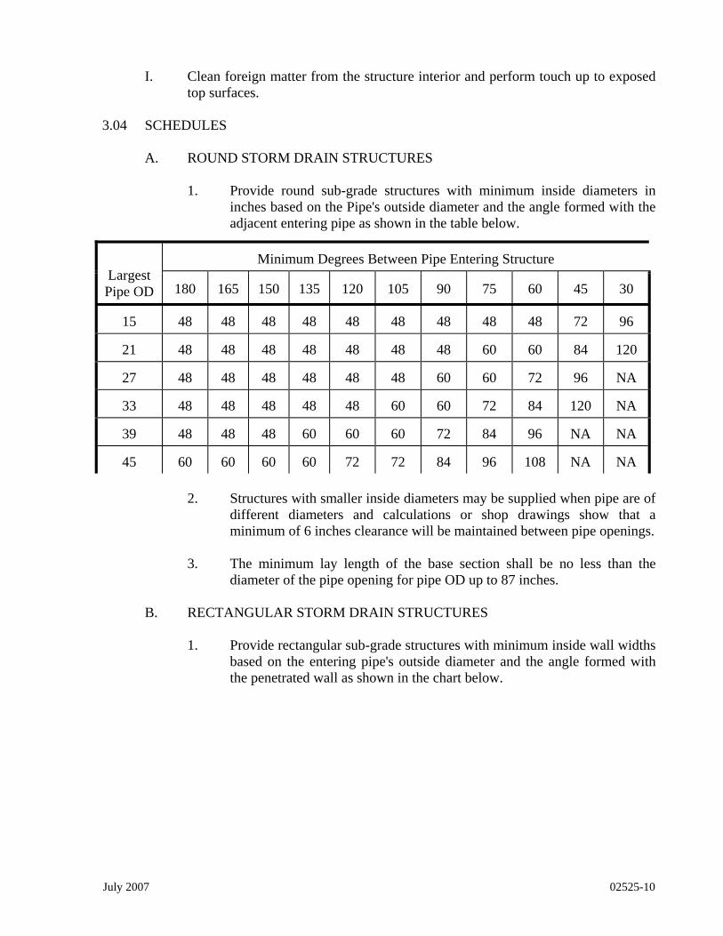
I. Clean foreign matter from the structure interior and perform touch up to exposed top surfaces.
3.04 SCHEDULES
A. ROUND STORM DRAIN STRUCTURES
1. Provide round sub-grade structures with minimum inside diameters in inches based on the Pipe's outside diameter and the angle formed with the adjacent entering pipe as shown in the table below.
Minimum Degrees Between Pipe Entering Structure Largest Pipe OD 180 165 150 135 120 105 90 75 60 45 30
15 48 48 48 48 48 48 48 48 48 72 96
21 48 48 48 48 48 48 48 60 60 84 120
27 48 48 48 48 48 48 60 60 72 96 NA
33 48 48 48 48 48 60 60 72 84 120 NA
39 48 48 48 60 60 60 72 84 96 NA NA
45 60 60 60 60 72 72 84 96 108 NA NA
2. Structures with smaller inside diameters may be supplied when pipe are of different diameters and calculations or shop drawings show that a minimum of 6 inches clearance will be maintained between pipe openings.
3. The minimum lay length of the base section shall be no less than the
diameter of the pipe opening for pipe OD up to 87 inches.
B. RECTANGULAR STORM DRAIN STRUCTURES
1. Provide rectangular sub-grade structures with minimum inside wall widths based on the entering pipe's outside diameter and the angle formed with the penetrated wall as shown in the chart below.
July 2007 02525-10
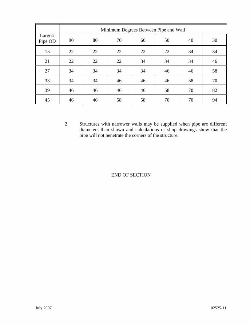
July 2007 02525-11
Minimum Degrees Between Pipe and Wall Largest Pipe OD 90 80 70 60 50 40 30
15 22 22 22 22 22 34 34
21 22 22 22 34 34 34 46
27 34 34 34 34 46 46 58
33 34 34 46 46 46 58 70
39 46 46 46 46 58 70 82
45 46 46 58 58 70 70 94
2. Structures with narrower walls may be supplied when pipe are different
diameters than shown and calculations or shop drawings show that the pipe will not penetrate the corners of the structure.
END OF SECTION

SECTION 02600
SANITARY SEWER GRAVITY SYSTEMS GENERAL 1.01 SECTION INCLUDES
A. Gravity Sewer piping, fittings, and accessories.
B. Connection of building sanitary sewer system to municipal sewers.
C. Manholes, cleanouts and accessories. 1.02 RELATED SECTIONS
A. Section 00800 – General Requirements
B. Section 02100 - Excavation
C. Section 02200 - Backfilling.
D. Section 02300 - Trenching.
E. Section 03250 - Concrete.
F. Section 03500 – Pre-cast Concrete Structures 1.03 REFERENCES - The standards listed below are included in this specification by
reference. Specifications cited shall refer to the latest standards revision under the same specification number, or to superseding specifications under a new number, except for provisions in revised specifications, which are clearly inapplicable.
A. AWWA C150 - Thickness Design of Ductile-Iron Pipe.
B. AWWA C151 - Ductile-Iron Pipe, Centrifugally Cast in Metal Molds or Sand-
Lined Molds, for Water or other Liquids.
C. AWWA C104 - Cement Mortar Lining for Ductile-Iron Pipe and Fittings for Water.
D. AWWA C111 - Rubber-Gasket Joints for Ductile-Iron and Grey-Iron Pressure
Pipe and Fittings.
E. AWWA C110 - Ductile-Iron Fittings and Grey-Iron Fittings, 3 in. through 48 in., for Water and other Liquids.
F. ASTM D 1719 - Poly (Vinyl Chloride) (PVC) Sewer Pipe and Fittings.
July 2007 02600-1

G. ASTM D 3034 - Type PSM Poly (Vinyl Chloride) (PVC) Sewer Pipe and Fittings.
H. ASTM D 2321 - Recommended Practice for Underground Installation of Flexible
Thermoplastic Sewer Pipe.
I. UNI-B-3-88 - Installation of Polyvinyl Chloride (PVC) Pressure Pipe. J. UNI-B-6-90 - Recommended Practice for Low-Pressure Air Testing of Installed
Sewer Pipe.
K. ASTM C 76 - Reinforced Concrete Culvert, Storm Drain, and Sewer Pipe.
L. ASTM A 48 - Gray Iron Castings.
M. ASTM C 478 – Pre-cast Reinforced Concrete Manhole Sections. N. City of North Myrtle Beach Standard Detail Drawings: S1 - S19.
1.04 REGULATORY REQUIREMENTS
A. Conform to all applicable SCDHEC Regulations for materials and installation for Sanitary Sewer Construction.
1.05 SUBMITTALS
A. Submit product data in accordance with Section 00800 for pipe, pipe accessories, manholes, manhole accessories, cleanouts and cleanout accessories, for approval prior to construction.
PRODUCTS 2.01 MANUFACTURERS
A. Pipe 1. U.S. Pipe
2. American Cast Iron Pipe Company. 3. Griffin Pipe Products Company. 4. McWane Cast Iron Pipe Company. 5. J M Pipe and Pipe Products. 6. Scepter Pipe.
B. Manholes
1. Vulcan 2. Taylor Concrete Products 3. Knight’s Pre-cast
July 2007 02600-2
4. Concrete Design 5. Tindall
C. Manhole Frame & Cover 1. Sumter Machinery Company Inc.
2. US Foundry D. Miscellaneous Accessories
1. Thunderline Corporation - Link Seals 2. MA Industries – Manhole Steps
E. Substitutions: Under provisions of Section 00800.
2.02 GENERAL
A. The Engineer will not permit intermixing of different types of pipe unless specified on the drawings or by approved written permission. If approved, pipe type changes shall occur only at manholes.
B. All pipe shall be of first quality with smooth interior and exterior surfaces, free
from cracks, blisters, honeycombs and other imperfections, and true to theoretical shapes and forms throughout the full length.
C. All pipe shall be subject to the inspection of the engineer at the pipe plant, trench,
or point of delivery, for purpose or culling and rejecting pipe (independent of laboratory test), which does not conform to the requirements of these specifications. The Engineer shall mark such pipe, and the Contractor shall remove it from the project site upon notice being received of its rejection.
D. Ductile Iron Pipe shall be used at depths of 14 feet and deeper, as directed by the
Engineer or as shown on the drawings. 2.03 GRAVITY SEWER PIPE MATERIALS
A. Ductile Iron Pipe: AWWA C150 & AWWA C151, Pressure Class 350, “Protecto 401” Ceramic Epoxy Lined Pipe or “Sewpercoat” Lined Pipe; inside nominal diameter as shown on drawings. Joints shall be push on unless otherwise shown on the drawings.
1. Ductile Iron Pipe Joint Device: AWWA C111 rubber gasket joint device.
B. Polyvinyl Chloride (PVC) Plastic Pipe: ASTM D3033 & ASTM D3034, SDR 35,
Type PSM, Polyvinyl Chloride (PVC) material; inside nominal diameter as shown. Bell and spigot style. Install in accordance with ASTM D2321. Laying length shall be 13 feet ± 1 foot.
1. Polyvinyl Chloride (PVC) Fittings: ASTM D 3034 with minimum wall
July 2007 02600-3

thickness of SDR35. Fittings in sizes through 8" shall be molded in one piece with elastomeric joints and minimum socket depths as specified in sections 6.2 and 7.3.2. Fittings 10" and larger shall be molded or fabricated in accordance with section 7.11 with manufacturer's standard pipe bells and gaskets.
2. Gaskets shall have a minimum cross-sectional area of 0.20 sq. in. and conform
to ASTM F 477.
3. PVC material shall have a cell classification of 12454-B or C as defined in ASTM D 1784.
C. Alternate Pipe Materials – Pipe that is not specified herein such as ABS, Vitrified
Clay, CIP etc. shall not be installed unless otherwise shown on the Plans, approved by the Engineer and approved within the SCDHEC construction permit.
2.04 PIPE ACCESSORIES
A. Fittings: Same material as pipe, molded or formed to suit pipe size and end design, in required "T", bends, elbows, cleanouts, reducers, traps, and other configurations required unless otherwise shown on drawings. Ductile iron fittings shall be lined to meet pipe material lining specification.
B. All services or lateral lines shall be connected to mainline sewers with in-line
service wyes only. Saddle wyes are not acceptable on new construction.
C. Link Seal - Wall seals for all pipe entering pump stations shall be installed in accordance with the manufacturer's installation instructions. All link seals shall be grouted in place after pipe placement.
2.05 MANHOLES
A. Manholes shall be pre-cast in accordance with Section 03500. B. Frame and Cover: Iron casting confirming to ASTM A48, Class 30C iron.
Minimum manhole cover diameter shall be 24 inches, and the manhole ring and cover assembly shall not weigh less than 300 pounds. For elevations above the 50-year flood level, frames and covers shall be Sumter Machinery Company, MF-6, MC-2, or equivalent. For elevations below the 50-year flood level, frames and covers shall be watertight Sumter machinery MF-50GT, MC-50GT or equivalent.
C. Shaft Construction and Eccentric Cone Top Section: Reinforced pre-cast or cast-
in-place concrete pipe sections, lipped male-female, "O" ring gasket type joints; cast steel ladder rungs into shaft sections at 12 inches; nominal shaft diameter of 48,60, 72, 96 inches as shown on the drawings.
D. Drop Manholes and Drop Connections shall be required where the invert
differential is 24-inches or greater and shall be installed as shown on the Plans and standard detail drawings, or as directed by the Engineer.
July 2007 02600-4

E. Manhole Steps: Neoprene coated steel steps cast or driven into manhole wall, 11 inches square and projecting from the wall 6 inches. Steps are to be a maximum of 16 inches on center.
F. Rubber Boots: All manholes to be equipped with rubber boots and all stainless
steel bands at each pipe portal. G. Coatings: Manhole coating shall consist of 21 mils, Kop-Coat 300-M Coal Tar
Epoxy applied to the interior vertical surfaces as recommended by the manufacturer. Manhole coating shall be as shown on the plans or as specified elsewhere herein.
2.06 FILL MATERIAL
A. Ductile Iron Pipe: Acceptable native materials as specified in Section 02200.
B. Polyvinyl Chloride (PVC) Plastic Pipe: Bed in accordance with bedding detail on
drawings using material specified in Section 02200. EXECUTION 3.01 GENERAL
A. The Contractor shall furnish all material and labor, and construct the gravity sewers shown on the drawings, including all clearing, grubbing, excavating, sheathing, backfilling, foundations, manholes, and other appurtenances.
B. The work shall include all ditching, pumping, bailing, draining, flushing, testing,
and all provisions necessary to protect and maintain buildings, fences, water and gas pipes, drainage culverts, power and telephone lines and cables, and other structures.
C. The contractor shall be responsible for the cleaning away of all rubbish and
surplus materials upon completion of the work required to build and put in complete working order the specified sewer and all structures appertaining thereto.
D. All sewers and appurtenances shall be cleared of all foreign debris.
3.02 ORDER OF WORK
A. The Owner reserves the right to direct the Contractor as to which portions of work should be constructed first, and upon order of the Engineer, to verify that any complete portion of work is as specified and acceptable for service.
3.03 HIGHWAYS, STREETS, AND PUBLIC PROPERTY
A. The Contractor shall fully adhere to the SCDOT Permit while operating in any
July 2007 02600-5

July 2007 02600-6
state right-of-way and all construction techniques shall comply with the current edition of the State Highway Department Standard Specifications and Traffic Control Manual.
B. Through traffic shall be maintained at all times during construction of sewer
across all streets and highways. If the open cut method is used, two separate cuts must be made and one lane of traffic must be open at all times.
C. The Contractor shall obtain, by agreement with property owner, any additional
space required for construction on private property. 3.04 EXISTING UTILITIES AND STRUCTURES
A. Any existing utilities, structures, monuments, etc. damaged by the Contractor shall be repaired or replaced by the Contractor at his own expense.
B. The approximate position of certain known underground lines is shown on the
drawings for information only.
C. The Contractor shall be responsible for having all underground utilities located by the appropriate party. Seventy-two (72) hours advance notice is required for utility locations.
3.05 POTABLE WATER PROTECTION (SEPARATION OF WATER & SEWER LINES)
A. Adequate provision shall be made for the protection of potable water supplies from possible leakage from sewers located near water lines.
B. There shall be no physical connection between a public water supply system and a
sewer system. No potable water main shall pass through or come into contact with any part of a sewer manhole.
C. Where possible, sewer mains should be located at least ten (10) feet horizontally
from existing or proposed water main then:
1. Sewer will be laid in a separate trench, with the elevation of the top of the sewer main at least eighteen (18) inches below the bottom of the water main, or:
2. Sewer will be laid in the same trench as the water main with the water
main located on a bench of undisturbed earth, and with the elevation of the top of the sewer at least eighteen (18) inches below the bottom of the water main, or:
3. If conditions prevent the eighteen (18) inch vertical separation, then the
sewer will be laid under the water main and both the water and sewer shall be constructed of ductile iron pipe for a distance of ten (10) feet on each side of the crossing. The water and sewer lines will be pressure tested to assure water tightness prior to backfilling.

D. When conditions require a sewer line to cross over a water main, both the water main and sewer line shall be constructed of ductile iron pipe for a distance of ten (10) feet on each side of the crossing. The water and sewer lines will be pressure tested to assure water tightness prior to backfilling.
E. Water/sewer line separation shall be in accordance with Section R61.58.4D (12)
of the State Primary Drinking Water Regulations. F. When it is not possible to maintain the separation distances specified in the
regulation above, the Engineer may allow an alternative design subject to approval from SCDHEC. The alternative design shall: 1. Maximize the distance between the water main and sewer line and the joints of each; 2. Use materials that meet the state regulatory requirement (R61.58.4) and 3. Allow adequate distance for maintenance and repairs on each line without causing damage to the other line.
3.06 PREPARATION
A. Hand trim excavations to required elevations. Correct over excavation with fill material of fine aggregate.
B. Remove large stones or other hard matter, which could damage the pipe or
impede consistent backfilling or compaction. 3.07 INSTALLATION-PIPE
A. Install pipe, fittings, and accessories in accordance with ASTM D2321, and manufacturer's instructions. All sewer lines shall be installed with a minimum of 3-feet cover over the pipe unless otherwise shown on the plans and approved in the SCDHEC construction permit.
B. Pipe shall be protected during handling against impact shocks and free fall. Pipe
shall be kept clean at all times.
C. Lay pipe to slope gradient noted on drawings. Pipe laying shall begin at the lowest grade point with spigot ends pointing down grade and forming a uniform invert.
D. All surfaces of pipe to be jointed, as well as the rubber gaskets, shall be cleaned
and lubricated with a vegetable soap or other lubricating agent as per the manufacturer's recommendations. Seal joints watertight.
E. Pipe shall not be placed on blocking at any time unless approved by the Engineer,
and then only at manholes or other structures where temporary blocking may facilitate installation of the pipe. After the pipe has been installed, all blocking shall be removed and all voids filled with select material and compacted in place.
F. All end line pipe, temporary or permanent, shall be fully protected with a
watertight stopper to prevent water, earth, or other foreign debris from entering
July 2007 02600-7
the pipe.
G. Pipe of different material shall not be joined together unless directly specified by the Engineer. Changes in pipe material shall be made at manholes only.
3.08 INSTALLATION - MANHOLES
A. Minimum diameter of manholes shall be 4'-0" (48") and pre-cast manholes shall conform to all the requirements of ASTM C 478.
B. Form bottom of excavation clean and smooth to correct elevation. Establish
elevations and pipe inverts for inlets and outlets as indicated.
C. All invert channels shall be smooth and semi-circular in shape, conforming to the inside of the adjacent sewer pipe section. Changes in direction of flow shall be made with a smooth curve, as large in radius as the size of the manhole will allow. Changes in the size and grade of the channels shall be formed directly in the concrete of the manhole base. The floor of the manhole outside the channels shall be smooth and shall slope toward the channels not less than one inch per foot nor more than two inches per foot.
D. Make joints between concrete manholes and pipes entering manholes with the
resilient connectors specified for this purpose; install in accordance with the recommendations of the connector manufacturer.
E. Mount lid and frame level in grout, secured to top cone section at elevation
indicated. 3.09 SEWER SERVICES AND CLEANOUTS
A. All services shall have a watertight plug or cap at the end of the pipe.
B. Services, unless otherwise directed, shall extend from the main sewer line to the property line or street right-of-way. Install cleanouts as shown on the drawings.
C. The end of the service shall be marked with a pressure treated post marker
(4"x4") or a PVC marker (painted pine markers are not acceptable). All pressure treated markers shall be painted with an exterior weatherproof paint, green in color. The marker shall extend 6" above ground and not less than 3 feet below ground. It shall be placed exactly 3 feet further than the end of the service and on a line perpendicular to the centerline of the main. If the 3 feet cannot be obtained due to obstructions, the marker shall be set within 3 feet of the service end location.
D. All services and cleanouts shall be a minimum of 6 inches in diameter, unless
otherwise directed.
E. Services and cleanouts shall be of the same material as the main line sewer unless shown otherwise.
July 2007 02600-8

F. Cleanouts located in asphalt or concrete pavement shall be protected by a frame and cover as manufactured by Vulcan Foundry Inc., catalog number V-8503 or equivalent.
3.10 INSPECTION
A. All work done and materials furnished shall be subject to the inspection of the Engineer and his inspector. The Engineer reserves the right to mark rejected materials to distinguish them as such.
B. All improper work shall be reconstructed at the Contractor's expense.
C. All materials, which do not conform to the requirements of the specifications,
shall be removed and replaced with approved materials at the Contractor's expense.
3.11 PIPE TESTING
A. Mandrel:
1. A mandrel shall be pulled through PVC line sections at any time prior to or during the one-year warranty period. A 5% mandrel shall be used on any line, which has been installed for less than thirty days. After 30 days a 7 1/2% mandrel will be allowed.
2. An approved mandrel, proving ring, pulling ropes and cables shall be
provided by the Contractor for testing PVC pipe at no additional cost to the Owner.
3. The mandrel shall be hand-pulled through the pipe using no wrenched or
other mechanical devices except a pulley at the manhole invert. The pulley allows the mandrel to be pulled from ground level rather than from inside the manhole.
4. If, at any point in the pipe in question, one (1) man is unable to hand pull
the mandrel through the pipe, then the pipe will be deemed unacceptable. The failed pipe shall be re-excavated and the problem solved at the Contractor's expense.
B. Infiltration/Exfiltration Testing:
1. Measurements of infiltration/exfiltration will be made before sewage
flows are allowed in the sewers.
2. Measurements for infiltration shall be made using a V-notch weir or by measuring the volume directly. Measurements for exfiltration shall be made by bulk heading the sewer at the end of the lower grade, partially filling the manhole at the upper end and computing the volume of leakage from the extent of the diminished volume of water in the manhole during
July 2007 02600-9

July 2007 02600-10
the test period. (This method is only applicable for dry soil conditions). 3. All infiltration/exfiltration tests shall be conducted by the Contractor in the
presence of the Engineer. 4. All testing shall be at the expense of the Contractor.
5. Allowable limit of exfiltration and ground water infiltration for the entire
system of new sewer or any one trunk, interceptor or outfall sewer line, including connecting laterals, shall not exceed 100 gallons per day per inch of pipe diameter per mile of pipe. This rate will be applied to any length of pipe in order to isolate excessive infiltration/exfiltration areas.
C. Low Pressure Air Testing of Gravity Sewers:
1. Air testing may be performed in lieu of infiltration/exfiltration testing as
approved by the Engineer. All testing shall conform to ASTM F1417. 3.12 FIELD QUALITY CONTROL
A. Field inspection will be performed by the Engineer and/or Owner.
B. Materials testing (i.e., compaction, concrete strength, etc.) shall be performed as directed by the Engineer and as specified in Section 00800.
3.13 PROTECTION
A. Protect pipe from damage or displacement until backfilling operation is in progress.
END OF SECTION

SECTION 02625
SEWER FORCE MAIN SYSTEMS
GENERAL 1.01 SECTION INCLUDES
A. Sewer Force Main piping, fittings, and accessories.
B. Sewer Pump Station piping, fittings, checks, and valves. 1.02 RELATED SECTIONS
A. Section 02100 - Excavation
B. Section 02200 - Backfilling
C. Section 02300 - Trenching
D. Section 02600 - Sanitary Sewer Gravity Systems
E. Section 02650 - Sewage Pumping Stations
F. Section 03250 - Concrete
1.03 REFERENCES: The standards listed below are included in this specification by reference. Specifications cited shall refer to the latest standards revision under the same specification number, or to superseding specifications under a new number, except for provisions in revised specifications, which are clearly inapplicable.
A. ASTM A377 - Ductile Iron Pressure Sewer Pipe.
B. AWWA C111 - Rubber Gasket Joints for Cast Iron and Ductile Iron Pressure
Fittings.
C. ASTM D2241 - Polyvinyl Chloride (PVC) (SDR 26) (160 psi) Sewer Pipe.
D. ASTM D2774 - Recommended Practice for Underground Installation of Thermoplastic Pressure Piping.
E. AWWA C104 - Cement Mortar Lined Ductile Iron Pipe.
F. AWWA C105 - Polyethylene Encasement for Ductile Iron Pipe Systems.
G. AWWA C110 - Ductile Iron Fittings and Gray Iron Fittings, 3" through 48" for
water and other liquids.
July 2007 02625-1

H. AWWA C151 - Ductile Iron Pipe, Centrifugally Cast in Metal Molds or Sand Molds, for Water or Other Liquids.
I. AWWA C509 - Resilient Seated Gate Valves for Water and Sewerage Systems.
J. AWWA C600 - Installation of Ductile Iron Pressure Pipe and Fittings. K. AWWA C600.4 - Testing of Sewer Force Mains.
L. AWWA C900 - Polyvinyl Chloride (PVC) Pressure Pipe.
M. AWWA M23 - PVC Pipe Design and Installation. N. UNI-B-13 - Recommended Standard Performance Specification for Joint
Restraint Devices for use with Polyvinyl Chloride (PVC) Pipe. 1.04 REGULATORY REQUIREMENTS
A. Conform to all applicable SCDHEC Regulations for materials and installation for Sanitary Sewer Construction.
1.05 SUBMITTALS
A. Submit product data in accordance with Section 00800 for pipe, pipe accessories, manholes, manhole accessories, valve and valve accessories for approval prior to construction.
PRODUCTS 2.01 MANUFACTURERS
A. Pipe 1. U.S. Pipe 2. American Cast Iron Pipe Company. 3. Griffin Pipe Products Company. 4. McWane Cast Iron Pipe Company. 5. J M Pipe and Pipe Products. 6. Scepter Pipe.
B. Plug Valves 1. DeZurik
C. Gate Valves 1. Clow Corporation. 2. Mueller Company.
July 2007 02625-2

3. M & H Valve & Fitting Co. 4. American Darling
D. Air and Vacuum Valves 1. Crispin (Multiplex Manufacturing Co.) 2. M & H Valve & Fitting Co.
E. Manhole Frame & Cover 1. Dewey Bros. Inc. 2. Sumter Machinery Company Inc.
3. US Foundry
F. Manholes
1. Taylor Concrete Products Inc. 2. Concrete Designs 3. Tindall 4. Vulcan 5. Knight’s Pre-cast
G. Miscellaneous Accessories 1. Thunderline Corporation - Link Seals.
H. Substitutions: Under provisions of Section 00800.
2.02 GENERAL
A. These specifications shall apply to the materials to be furnished and installed to complete the sewer force main installations in accordance with the plans.
B. All pipe and fittings shall be of the class and type as indicated on the plans and/or
proposal designated herein.
C. The Engineer will not permit Intermixing of different types of pipe unless specified on the plans or with approved written permission.
D. All pipe shall be of first quality with smooth interior and exterior surfaces, free
from cracks, blisters, honeycombs and other imperfections, and true to theoretical shapes and forms throughout the full length.
E. All pipe shall be subject to the inspection of the engineer at the pipe plant, trench,
or point of delivery, for purpose of culling and rejecting pipe (independent of laboratory test), which does not conform to the requirements of these specifications. The Engineer shall mark such pipe, and the Contractor shall remove it from the project site upon notice being received of its rejection.
July 2007 02625-3

July 2007 02625-4
F. All sewer force mains installed shall be Polyvinyl Chloride (PVC) pipe for force mains 16 inches in diameter or less.
G. All sewer force mains greater than 16 inches in diameter shall be ductile iron pipe
ANSI/AWWA - C104/A21.4 or as otherwise noted.
H. As specific specifications are cited, the designation shall be construed to refer to the latest revision under the same specification number, or to superseding specifications under a new number, except for provisions in revised specifications, which are clearly inapplicable.
I. All sewer force main materials shall conform to one or more of the specifications
cited for each material classification noted below. 2.03 SEWER FORCE MAIN MATERIALS
A. Ductile Iron Pipe:
1. Pipe shall conform to AWWA C151, ASTM A746, and ASTM A377.
2. Pipe sizes 12" and smaller shall be Pressure Class 350.
3. Pipe sizes 14" and larger shall be Pressure Class 250.
4. The pipe shall be lined with “Protecto 401” ceramic epoxy coating or “Sewpercoat” calcium aluminate lining with epoxy coating.
5. Pipe shall be push-on, mechanical, flanged, or boltless ball joint (as
needed or as shown on the plans) and conform to AWWA C111 and Federal Specification WW-P-421-C; for flanged joints ASA-B16.1; and for boltless ball joints ASA-B-16-B.
6. Boltless ball joints shall lock and permit a deflection of up to 15 degrees.
The locking device shall include a spherical socket, spherical retainer, and locking ring.
B. POLYVINYL CHLORIDE PIPE (PVC)
1. PVC Pressure pipe shall be in accordance with the requirements of ASTM
D2321, latest revision; ASTM D2241, latest revision; and shall bear the National Sanitation Foundation Seal.
2. Pipe 4 inches through 12 inches in diameter shall be Class 150 DR 18.
(AWWA C900) 3. Pipe larger than 12 inches in diameter shall be Class 165 DR 25. (AWWA
C905)
4 Pipe less than 4 inches in diameter shall be rated for 160 psi (SDR 26).
5. Rubber rings shall be of uniform solid cross-section and conform to ASTM D1869 or the manufacturer's recommendations.
C. PLUG VALVES
1. Sewer Force Main Valves 12 inches in diameter or smaller shall be plug
valves.
2. Plug valves shall be DeZurik Series 100eccentric plug valves or approved equal.
3. Plug valves buried in the ground shall be furnished with mechanical joint
type end connections and a standard 2-inch square operating nut.
4. Plug valves shall be epoxy coated inside and out.
5. Plug valves located inside sewer pump stations or buildings are to have flanged joints with hand-wheel actuators.
6. All plug valves shall be eccentric plug valves unless otherwise specified.
7. All plug valves shall be rated for 175-psi working pressure and 350-psi
hydrostatic test pressure.
D. GATE VALVES
1. Sewer force main valves 14 inches in diameter and larger shall be resilient wedge gate valves (unless otherwise noted) and conform to AWWA Standard C-500 as latest revised.
2. Gate valves shall be of the non-rising stem type with O-ring seals.
3. All gate valves shall be furnished with mechanical joint type end
connections.
4. Gate valves shall be epoxy coated, painted inside and out by the valve manufacturer.
5. Gate valves 16 inches in diameter and larger shall be gear actuated with a
bypass valve and installed in a horizontal position.
6. All gate valves shall be equipped with a standard 2-inch square operation nut.
7. Gate Valves shall be Mueller, Clow, American-Darling, M & H, or
approved equal.
8. Gate valves shall be rated for 150-psi working pressure and 300-psi hydrostatic testing pressure.
July 2007 02625-5

E. TAPPING SLEEVES & VALVES
1. Tapping sleeves will be true mechanical joints (no fabricated sleeves). Mueller model H-615 or approved equal.
2. All tapping sleeves will be for cast iron, ductile iron, or PVC pipe.
(Unless otherwise noted.)
3. All tapping valves shall be Mueller model T-2360 resilient wedge gate valve or approved equal.
4. Tapping valves shall have a standard 2-inch square operating nut.
F. VALVE BOX
1. Valve boxes shall be at least 5 1/4" in diameter, cast iron, and adjustable
screw type with extension to grade. Cast iron box shall have a heavy coat of bituminous paint.
2. As required, extension stems shall be provided to raise valve operating nut
to 36 inches below grade.
3. Each valve box is to be mounted flush with the finished grade.
4. Crushed stone backfill will be required between and around the valve and valve box.
5. Valve boxes in grassed areas shall have a pre-cast concrete collar mounted
flush with the final grade.
6. Valve boxes in pavement areas shall be brought flush with the proposed pavement elevation.
7. Valve boxes to read "SEWER" on the top cover.
G. CHECK VALVES
1. Check valves buried in the ground and laid in the horizontal direction shall
be mechanical joint gravity type check valve, Mueller model A-2600-20 or approved equal.
2. Check valves installed in sewer pump stations or valve vaults that are to
be installed in the horizontal or vertical direction shall be a flanged lever and spring operation check valve, Mueller model A-2600-6-02, a flanged sinking ball type check valve, FLYGT HDL valve or approved equal.
H. SEWER AIR RELEASE VALVES
1. All air release valves shall be Crispin Model No. S20B pressure sewer
July 2007 02625-6

valve as manufactured by Multiplex Manufacturing Company, Berwick, Pennsylvania, or approved equal.
2. Valves shall be a long body design capable of venting not less than 15
standard cubic feet of free air per minute at 10 pounds working pressure.
3. Valve inlet shall be 2 inches in diameter and shall be furnished with a 2-inch shutoff valve.
4. Automatic air release valves shall be located at each high point along the
main as shown on the Plans to allow air to escape the main. 2.04 PIPE ACCESSORIES
A. Fittings: All fittings shall be ductile iron, mechanical joint to suit pipe size and material, in required tees, bends, elbows, cleanouts, reducers, traps, and other configurations required unless otherwise shown on plans. Fittings shall be lined to meet the pipe lining specification.
B. Link Seal: Wall seals for all pipe entering pump station shall be installed in
accordance with the manufacturer's installation instructions. All link seals shall be grouted in place after pipe placement.
2.05 MANHOLES
A. Frame and Cover: Iron castings conforming to ASTM A48, Class 30C iron. Minimum manhole cover diameter shall be 24 inches, and the manhole ring and cover assembly shall not weight less than 300 pounds. For elevations above the 50-year flood level, frames and covers shall be Sumter Machinery Co. of Sumter, S.C., MF-6, and MC-2 or approved equal. For elevations below the 50-year flood level, frames and covers shall be water tight Sumter Machinery MF-50GT, MC-50GT or approved equal.
B. Shaft Construction and Eccentric Cone Top Section: Reinforced pre-cast or cast-
in-place concrete pipe sections, lipped male/female, "O" Ring gasket type joints; neoprene coated steel ladder rungs into shaft sections at 12 inches; nominal shaft diameter of 48, 60, 72, 96 inches as shown on the plans.
C. Manhole Steps: Neoprene coated steel steps cast into manhole wall, 11 inches
square and projecting from the wall 6 inches. Steps are to be a maximum of 16 inches on center.
2.06 FILL MATERIAL
A. Ductile Iron Pipe: Acceptable native materials as specified in Section 2200.
B. Polyvinyl Chloride (PVC) Plastic Pipe: Bed in accordance with bedding detail on plans using material specified in Section 2200.
July 2007 02625-7

EXECUTION 3.01 GENERAL
A. The Contractor shall furnish all material and labor, and construct the sewer force mains shown on the plans, including all clearing, grubbing, excavating, sheathing, backfilling, foundations, manholes, and other appurtenances, as shown on the plans or specified.
B. The work shall include all ditching, pumping, bailing, draining, dewatering,
flushing, testing, and all provisions necessary to protect and maintain buildings, fences, water and gas pipes, drainage culverts, power and telephone lines and cables, and other structures.
C. The Contractor shall be responsible for the cleaning away of all rubbish, surplus
materials, and the furnishing of all materials, tools, implements, and labor required to build and put in complete working order the specified sewers and all structures appertaining thereto.
D. All sewers and appurtenances shall be cleared of all foreign debris.
3.02 SURVEYS, POINTS, AND INSTRUCTIONS
A. The Engineer shall furnish horizontal and vertical control points as may be necessary. The Contractor shall create his own alignment between each horizontal control points and be responsible for establishing elevations of said points. This shall not relieve the Contractor of the responsibility to make careful and accurate measurements and for constructing the work accurately to the lines and grades furnished by the Engineer.
B. The Contractor shall give the Engineer reasonable notice (72 hours minimum) of
his requirements for such control survey lines and grades as he may require.
C. The Contractor shall furnish and place, as directed, all necessary guide boards and appurtenances, and give such other incidental assistance at the site as may be required by the Engineer for staking out the work.
D. The Contractor shall temporarily suspend construction operations, which interfere
with the Owner’s activities. Operations will be suspended for as long as the Engineer deems necessary.
E. The Contractor shall carefully preserve the points furnished by the Engineer. Any
re-staking required will be at the cost of the Contractor.
F. The Contractor shall receive no extra compensation for any materials or services furnished by him incidental to these operations of the Engineer.
July 2007 02625-8

July 2007 02625-9
3.03 ORDER OF WORK
A. The Owner reserves the right to direct the Contractor as to which portions of work should be constructed first, and upon order of the Engineer to verify that any complete portion of the work is as specified and acceptable for service.
3.04 HIGHWAYS, STREETS, AND PUBLIC PROPERTY
A. The Contractor's operations in highways or public streets shall be confined to as small a space as is practicable, so as not to cause undue inconvenience to the public or abutting properties, and shall be subject to the approval of the Engineer.
B. The Contractor shall obtain, by agreement with property owner, any additional
space required for construction on private property at no cost to the Owner of the Project.
C. The Contractor shall fully adhere to the SCDOT Encroachment Permit while
operating in any State Right-of-Way.
D. Roadway crossings shall be accomplished by open ditch construction or by boring under pavement as required by the State.
E. All materials shall be approved by the Engineer prior to the start of work.
F. Pavement, base, and sub-grade courses which must be removed for constructing
sewers and appurtenances in or across highways, roadways, and streets shall be replaced with the same general class and type of material used in the initial construction unless specified differently on the plans or in the specifications.
G. Through traffic shall be maintained at all times during construction of sewers
across all streets and highways. If the open cut method is used, two separate cuts must be made and one lane of traffic must be open at all times.
H. All construction techniques shall comply with the current edition of the SCDOT
Standard Specifications and Traffic Control Manual.
I. The Contractor shall provide suitable bridges, approved by the Engineer, for any area where traffic will cross a trench.
3.05 EXISTING UTILITIES AND STRUCTURES
A. The Contractor shall give written notice (copy to the Engineer) to the SCDOT, other Municipalities, and Public Service Corporations whose poles, wires, pipes, conduits, survey monuments, benchmarks, or other structures/utilities may be affected by his operations.
B. Seventy-two hour advance notice is required for utility locations.
C. Any existing utilities, structures, monuments, etc. damaged by the Contractor

shall be repaired or replaced by the Contractor at his own expense.
D. The approximate position of certain known underground lines is shown on the plans for information only. Existing small service lines are not shown.
E. The Contractor shall locate all utilities by use of an electronic pipe locator or
other satisfactory methods.
F. The Contractor shall excavate and expose all existing underground lines in advance of trenching operations.
G. The Contractor may, with the Owner or Engineer's consent, remove any
obstructions to his operations, but the obstructions shall be removed and replaced at the Contractor's expense.
H. Removing and relaying of such lines and appurtenances due to interference with
the proposed line and grade, in the opinion of the Engineer, will be completed at the expense of the Contractor, unless otherwise shown on the plans or in the contract documents.
3.06 POTABLE WATER PROTECTION (SEPARATION OF WATER & SEWER LINES)
A. Adequate provision shall be made for the protection of potable water supplies from possible leakage from sewers located near water lines.
B. There shall be no physical connection between a public water supply system and a
sewer system. No potable water main shall pass through or come in contact with any part of a sewer manhole.
C. Where possible, sewer mains should be located at least ten (10) feet horizontally
from existing or proposed water main then:
1. Sewer will be laid in a separate trench, with the elevation of the top of the sewer main at least eighteen (18) inches below the bottom of the water main, or:
2. Sewer will be laid in the same trench as the water main with the water
main located on a bench of undisturbed earth, and with the elevation of the top of the sewer at least eighteen (18) inches below the bottom of the water main, or:
3. If conditions prevent the eighteen (18) inch vertical separation, then the
sewer will be laid under the water main and both the water and sewer shall be constructed of ductile iron pipe for a distance of ten (10) feet on each side of the crossing. The water and sewer lines will be pressure tested to assure water tightness prior to backfilling.
D. When conditions require a sewer line to cross over a water main, both the water
main and sewer line shall be constructed of ductile iron pipe for a distance of ten
July 2007 02625-10
(10) feet on each side of the crossing. The water and sewer lines will be pressure tested to assure water tightness prior to backfilling.
E. Water/sewer line separation shall be in accordance with Section R61.58.4D (12)
of the State Primary Drinking Water Regulations. F. When it is not possible to maintain the separation distances specified in the
regulation above, the Engineer may allow an alternative design subject to approval from SCDHEC. The alternative design shall: 1. Maximize the distance between the water main and sewer line and the joints of each; 2. Use materials that meet the state regulatory requirement (R61.58.4) and 3. Allow adequate distance for maintenance and repairs on each line without causing damage to the other line.
3.07 LIGHTS AND PROTECTION
A. The Contractor shall erect and maintain such strong and suitable barriers and such warning lights as will effectively prevent the occurrence of any accident to health, limb, or property.
B. Lights shall be maintained between the hours of sunset and sunrise, or during any
period as directed by the Engineer.
C. Where pipe lines are to be constructed in the streets, highways or roadways, the Contractor shall take all precautions and comply with all requirements, as may be necessary, to protect the improvements. Including installation and maintenance of warning signs, lights, and barricades for the protection of traffic.
3.08 EXCAVATION
A. Contractor to excavate in accordance with Section 2100 and the following.
B. The Contractor shall do all excavation of whatever substances are encountered to the depth shown on the plans.
C. Prior to any excavation Contractor shall provide adequate protection (as long as
necessary to prevent damage) for any part or parts of the project site to remain (lawns, sidewalks, fences, landscape, hydrants, etc.).
D. Any and all damaged items shall be repaired or replaced in such a manner that the
items in question are returned to their original or better condition at the Contractor's expense.
E. Unstable soil shall be removed and replaced with mechanically tamped gravel or
crushed stone at no additional cost to the Owner. The Engineer shall determine the depth of removal of unstable soil.
F. Excavation for manholes shall have a minimum of twelve (12) inches clearance
on all sides.
July 2007 02625-11

G. Remove any water accumulated in excavation at no additional cost to Owner.
H. Excavation shall not be carried below the required level. Excess excavation below the required level shall be backfilled at the Contractor's expense with earth, sand, gravel, or concrete, as directed by the Engineer, and thoroughly tamped to the required proctor.
I. At locations where existing walls or fences will be removed to permit the
installation of the proposed sewer line, the Contractor shall remove and reset the wall/fence as rapidly as practicable to permit the installation. Fences/walls shall be resent in their original location in condition equal or better than prior to their removal. The Contractor will be required to establish temporary fencing or barriers for protection of children, livestock, etc. during construction.
3.09 TRENCHING
A. Contractor to construct all trenching in accordance with Section 2300 and the following.
B. Trench width shall be wide enough to provide adequate space for workman to
place and joint the pipe properly.
C. Trench bottom to be rounded to allow pipe to rest firmly on undisturbed soil or compacted bedding.
D. Bell holes shall be excavated accurately to size by hand. In rock, excavation shall
be carried 6 inches below the bottom of the pipe. Loose earth or gravel shall be used for backfill and tamped thoroughly.
E. Contractor shall provide and use all bracing, sheathing, and shoring necessary to
perform and protect all excavations as shown on the plans, as required for safety, as directed by the Engineer, or to conform to governing laws.
F. Excavated material shall be stockpiled in such a manner to prevent interference
with any traffic, and existing or proposed structures or utilities.
G. Equipment, materials, trenches, and excavations which may cause a hazard or serve as obstructions to either vehicular or pedestrian traffic, shall be enclosed by fences or barricades, adequately lighted, to protect persons from injury and to avoid property damage.
H. The Contractor shall furnish temporary support, adequate protection and
maintenance of all underground and surface structures, drains, sewers, and other obstructions encountered in the process of work.
I. Where traffic must cross open trenches, the Contractor shall provide suitable
bridges, which shall be subject to approval by the Engineer. J. All safety requirements of OSHA must be followed, including but not limited to
July 2007 02625-12

trenching, shoring, confined space, ingress/egress, etc.
K. Trenches shall be properly dewatered prior to placement of the pipe. Where running sand is encountered well pointing method will be used. If soil conditions prohibit the well pointing method, then french drains of crushed stone or gravel shall be constructed to drain to suitably located sumps and the water removed by bailing or pumping. The Contractor shall provide all labor, materials, tools, and equipment required for the dewatering process at no additional cost to the Owner.
L. Not more than 200 feet of trench shall be opened in advance of pipe laying unless
otherwise approved by the Engineer. M. Wherever the sub-grade is by nature too soft or mucky, in the opinion of the
Engineer, for the proper installation of the sewer force main, he may order the Contractor to undercut the trench and backfill with crushed stone or gravel, 3/4" in size and less.
N. Trenches shall be excavated a sufficient distance in advance of laying the pipe, to
prevent the entry of ground water, earth or debris during the construction. The exposed end of all pipes shall be fully protected with a watertight stopper to prevent water, earth, or other substances from entering the pipe during periods when work is not in progress.
O. The invert profile, as shown on the plans, shall be followed except where changes
are authorized in writing by the Engineer to avoid existing structures or to conform to the topography.
P. The depth of the trench shall be increased where necessary to provide a smoothly
curved profile or to avoid existing structures.
Q. The trench shall be excavated in such a manner as to provide uniform and continuous bearing and support for the pipe, and excavated to the depth required to give a minimum of 36 inches of cover for the pipe from the finished grade to the top outside of the pipe barrel, except under roadways where the minimum cover shall be 30 inches from the sub grade to the top of the pipe barrel and at air release valves where the minimum cover shall be 54 inches from the sub-grade to the outside top of the pipe barrel.
R. The depth of cover may be modified at creek crossings or at other dips in the
profile, when approved by the Engineer, provided that the cover is not less than 36 inches for more than one full station (100) feet.
S. Bell holes shall be provided at each joint to permit the joints to be "made-up"
properly.
T. Where the soil at the bottom of the trench is not uniformly good, with stone, dry clay, hard pan, shale, or cemented gravel exposed, the trench shall be excavated to at least three inches and not more than six inches below the specified grade, and shall be backfilled to grade with material, approved by the Engineer, containing
July 2007 02625-13

no rocks, gravel or cinders, in layers not to exceed four inches loose depth. The bedding shall be finished by means of hand tools so as to provide uniform and continuous bearing and support for the pipe.
U. Where the bottom of the trench at grade is found to be unstable, or includes ashes,
cinders, all types of refuse, vegetable or other organic material, the Contractor shall excavate and remove such unsuitable material to the width and depth ordered by the Engineer. The trench shall be backfilled to bedding grade with approved material in four-inch layers to loose depth. Each layer shall be thoroughly compacted to a density specified by the Engineer. The bedding shall be finished by means of hand tools so as to provide a uniform and continuous bearing and support for the pipe. There will be no additional compensation for such excavation and backfill.
V. Where the bottom of trench grade is found to consist of material which is unstable
to such a degree that, in the opinion of the Engineer, it cannot be removed and replaced with material suitable to support the pipe properly, the Contractor shall construct a foundation for the pipe, consisting of concrete, pilings, timber, or other suitable materials, as directed by the Engineer. Special foundations, if not called for on the plans, shall be paid for in accordance with the proposal, or at a price agreed upon by the Owner and Contractor and approved by the Engineer.
3.10 EXAMINATION
A. Verify that trench cut and excavation base is ready to receive work, and excavations, dimensions, and elevations are as indicated on Drawings.
B. Beginning of installation means acceptance of existing conditions.
3.11 PREPARATION
A. Hand trim excavations to required elevations. Correct over excavation with fill material of fine aggregate.
B. Remove large stones or other hard matter, which could damage pipe or impede
consistent backfilling or compaction. 3.12 INSTALLATION - PIPE
A. GENERAL
1. Install PVC pipe, fittings and accessories in accordance with ASTM D2241, ASTM D2321, ASTM D2774 and manufacturer's instructions. Install ductile iron pipe, fittings and accessories in accordance with ASTM A377, AWWA C600, and manufacturer's instructions. Seal joints watertight.
2. All pipes and fittings shall be protected during handling against impact
shocks and free fall. Pipes and fittings shall be cleaned before they are
July 2007 02625-14
laid, and shall be kept clean at all times.
3. All pipe and fittings shall be carefully examined for defects and no piece shall be laid which is known to be defective. Before lowering, and while suspended, cast and ductile iron pipe may be gently tapped with a hammer to sound for cracks. Any defective, damaged, or unsound pipe shall be rejected.
4. If any defective piece is discovered after having been laid, it shall be
removed and replaced with a sound one at the Contractor's expense.
5. The pipe shall be supported its full length by the uniform grade of the trench, and a bell hole shall be dug at each joint, said hole being of sufficient size to ensure the proper "making up" of each joint.
6. Pipe ends shall not be left open at the end of a day's work or during
temporary suspension of construction, but shall be securely covered to prevent the entry of foreign matter or small animals.
7. Under no circumstances will pipe deflection at any joint exceed the
Manufacturer's recommendations. Excessive deflection, which puts pipe joints in strain, will not be permitted.
8. Horizontal and vertical curvature, where fittings are not specified, can be
obtained by cutting pipe to short lengths.
9. When cutting short lengths of pipe, a pipe cutter will be used, and care will be taken to make the cut at right angles to the centerline of the pipe. In the case of "push-on" pipe, the cut ends shall be tapered with a portable grinder or coarse file to match the manufactured taper.
10. Where the use of nuts, bolts, washers, rods, straps, and clamps are
required due to the peculiarities of the installation, these items shall be installed and be of the size and dimension as shown on the plans. After installation, and before backfilling, all the above items shall be painted with bituminous paint or coal tar enamel. In lieu of the above, accessories and fittings shall be provided using stainless steel or other non-corrosive metals.
11. Any pipe, fitting, or accessory not meeting the specified ASTM Standard
shall not be used.
12. Place pipe on approved bedding in accordance with the plans and specifications.
13. Lay pipe to slope gradient noted on Drawings.
14. Pipe laying shall begin at the lowest grade point with spigot ends pointing
down grade and forming a uniform invert.
July 2007 02625-15

15. Pipe shall not be placed on blocking at any time unless approved by the Engineer, and then only at manholes or other structures where temporary blocking may facilitate installation of the pipe. After the pipe has been installed, all blocking shall be removed and all voids filled with select material and compacted in place.
16. Increase compaction of each successive lift. Do no displace or damage
pipe when compacting.
B. "PUSH-ON" JOINT PIPE
1. "Push-On" type joints, such as “Tyton”, "Ring Tite", "Fastite", or approved equal, shall be prepared by removing all dirt or foreign material from the bell end of the pipe and inserting the gasket.
2. The spigot end of the pipe shall be prepared by cleaning and applying a
thin coat of approved lubricant after which the spigot end is centered in the bell and jacked on by using a special jack and choker sling.
3. The procedure in making up this joint shall be performed in accordance
with the recommendations of the manufacturer.
C. MECHANICAL JOINT PIPE
1. When "making-up" mechanical joints, the spigot end of each pipe shall be inserted into the adjoining bell to within 1/8 inch of the total depth of the bell.
2. The pipe shall be properly centered and have uniform space all around for
reception of the packing material.
3. The packing material bolts; nuts, and other accessories used in making mechanical or sleeve type joints shall be obtained from the manufacturer of the pipe.
4. The surface of the spigot and bell are to be brushed thoroughly with a wire
brush just prior to assembling. The spigot end is to be brushed with soapy water just prior to slipping the gasket on and entering it into the bell.
5. When tightening bolts, it is essential that the gland be brought up to the
pipe flange evenly, maintaining approximately the same distance between the gland and the face of the flange at all points around the socket. This is to be done by partially tightening the bottom bolt first, then the top bolt, next two bolts at either side, and last, the remaining bolts. Repeat this cycle until all bolts are within the range of the torques listed below:
July 2007 02625-16

BOLT SIZE RANGE OF TORQUES DIA. FT./LBS. 5/8" 40-60 3/4" 60-90 1" 70-100 1-1/4" 90-120
If effective sealing is not obtained at the maximum torques indicated above, the joint must be disassembled and reassembled.
D. FLANGED JOINT PIPE
1. All flanged faces shall be free of all dirt or foreign material. Each face
shall be cleaned prior to installing the gasket. 2. Flanges should be inspected to make sure that the flange is true and the
boltholes line up with each other. 3. Flanges should be tightened to the proper torques listed in the mechanical
joint pipe section. 3.14 INSPECTION
A. All work done and materials furnished shall be subject to the inspection of the Engineer.
B. All improper work shall be reconstructed at the Contractor's expense.
C. All materials, which do not conform to the requirements of the specifications,
shall be removed from the work upon notice being received from the Engineer of the rejection of such materials. The rejected materials shall be removed and replaced with approved materials at the Contractor's expense.
D. The Engineer reserves the right to mark rejected materials to distinguish them as
such. 3.15 MECHANICAL RESTRAINTS (THRUST RESTRAINT)
A. Lines shall have restrained joints at all tees, bends, plugs, crosses, valves, and hydrants or as directed by the Engineer.
B. Acceptable methods for joint restraint shall be the use of metal tie-rods or EBAA
Iron Inc., MEGALUG or equivalent. C. Retainers for pipe bells shall be required with the use of the MEGALUG
restraints. D. Concrete blocking shall not be used.
July 2007 02625-17

3.16 BACKFILLING
A. Contractor to backfill in accordance with Section 2200 and the following. B. All trenches and excavation shall be backfilled immediately after the pipes are
laid therein, unless other protection of the pipeline is directed.
C. The backfilling materials shall be selected and deposited with special reference to the future safety of the pipes.
D. Backfill material shall be free from cinders, ashes, refuse, vegetable or other
organic materials, boulders, large rocks, or stones. However, from one foot above the top of the pipe to the original ground or the sub-grade, material containing stones up to four inches in their greatest dimension may be used, unless otherwise directed by the Engineer.
E. The backfill material shall be deposited in the trench for its full width in six-inch
layers loose depth to the height of one foot above the pipe. Except where special methods of bedding and tamping are provided for, clean earth, sand, or rock dust shall be solidly tamped and compacted as hereinafter described.
F. Backfilling shall not be done in freezing weather, except by permission of the
Engineer, and it shall not be done with frozen material. No backfilling shall be done where the material already in the trench is frozen.
G. From the bottom of the trench to the centerline of the pipe, the backfill material
shall be placed by hand and compacted with approved hand tamps to the required proctor. From the centerline of the pipe, to a height of one foot above the pipe, the backfill shall be placed by hand and compacted by use of approved mechanical tampers to the required proctor. The Contractor shall use special care in placing this portion of the backfill so as to avoid injuring or moving the pipe. The remainder of the backfill in the trench shall be placed by hand or mechanical means in the specified lifts and compacted by the approved mechanical tamper to the specified proctor.
H. Walking or working on the completed pipe lines, except as may be necessary in
tamping or backfilling, shall not be permitted until the trench has been backfilled to a height of at least two feet over the top of the pipe.
I. After placing the backfill up to a level slightly below the natural ground surface,
surplus excavation shall be bermed and maintained in a suitable manner as to concentrate and pond runoff from rains over the trench. After sufficient settlement has been obtained, in the opinion of the Engineer, the Contractor shall complete the dressing, removal of surplus materials, and surface cleanup in accordance with these specifications.
J. Whenever the trenches have not been properly filled, or if settlement occurs, they
shall be refilled, smoothed off, and finally made to conform to the surface of the ground. Backfilling shall be carefully performed and the original surface restored
July 2007 02625-18

to the full satisfaction of the Engineer or Owner. K. Backfill in open trenches across sidewalks and in roadways shall be made as
specified above, except that fill above the pipes shall be deposited in layers not to exceed six inches and thoroughly compacted to the specified proctor.
L. Excess material not needed for backfill, and material unsuitable for backfill, shall
be removed from the site and disposed of as directed by the Engineer.
M. Additional backfill material as required to make up deficiency, or to replace unsuitable excavated material, shall be furnished by the Contractor at no additional cost from approved borrow pits or from excavations on roadways.
N. The Contractor shall backfill the trench to the original grade or as specified in the
plans.
O. The construction site shall be left in a neat and orderly condition to the Engineer or Owner's satisfaction.
3.17 TESTING AND LEAKAGE
A. Each completed section of the pipeline shall be plugged at both ends and slowly filled with water. As the force main is being filled for the hydrostatic pressure test, all air shall be expelled from the pipe through blow-offs, air release valves, or temporary taps. An automatic air release valve shall be placed at each high point as shown on the plans to prevent air locking.
B. The force main shall be subjected to a hydrostatic pressure of 150 pounds per
square inch for a period of two hours. All testing shall be in accordance with AWWA C600 (DIP) and/or AWWA C605 (PVC)
C. The leakage during the test shall not be more than calculated using the following
table or AWWA C-600-4.
D. The required hydrostatic pressure shall be applied to the force main by means of a hand pump for small lines or by the use of a gasoline pump or fire engine for larger lines.
E. During the test the lines shall be thoroughly examined for leakage at the joints and
repaired where applicable. All visible leaks shall be repaired, regardless of leakage amount.
F. Any cracked or defective pipes, fittings, or valves discovered in consequence of
the pressure test shall be removed and replaced by the Contractor at his own expense. Then the force main is to be retested to the required pressure for two hours.
G. In the event that the pipeline is tested in sections and temporary thrust blocking is
required, a temporary plug or cap shall be installed and blocked with a screw jack,
July 2007 02625-19

July 2007 02625-20
firmly braced against the end of the trench or against a heavy timber embedded into the sides of the trench.
H. Where pipeline construction ties into existing lines, and where it is not practicable
to make a hydrostatic pressure test, the Contractor shall leave this section of pipeline uncovered at each applicable joint for inspection for a period of 48 hours after the connection has been made and the line is placed in service. The Contractor shall make the necessary restraints to make sure that the force main does not blow apart at these uncovered joints. The Contractor shall immediately correct any leakage discovered in these joints.
I. All pressure tests must be witnessed for the two-hour duration by the Engineer's
Inspector or Owner's Inspector. The Contractor is to notify the Inspector a minimum of 24 hours prior to the pressure test.
J. The allowable leakage for a period of two hours shall be calculated using the
following formula: S*D*(P)1/2 L = ________ 133,200 Where L = (Leakage in gallons per hour) S = (Length of Pipe being tested in feet) D = (Diameter of the pipe in inches) P = (Test pressure in psi) Test shall last for a period of 2 hours. 3.18 CLEANUP AND MAINTENANCE
A. Cleanup shall follow immediately behind the pipe paying and backfilling operations. The Owner shall keep pipelines and the construction site clean and serviceable until final inspection and acceptance.
3.19 FIELD QUALITY CONTROL
A. Field inspection will be performed by the Engineer and the independent testing lab.
3.20 PROTECTION
A. Protect pipe from damage or displacement until backfilling is in progress.
END OF SECTION
SECTION 02650
SEWAGE PUMPING STATIONS
GENERAL 1.01 SECTION INCLUDES
A. Pumps.
B. Pump Station Support Equipment.
C. Wetwell.
D. Electrical Controls.
E. Fencing. 1.02 RELATED SECTIONS
A. Section 02100 - Excavation
B. Section 02200 - Backfilling
C. Section 02300 - Trenching
D. Section 02600 - Sanitary Sewer Gravity Systems.
E. Section 02625 - Sewer Force Main Systems.
F. Section 03250 - Concrete
G. Section 03500 – Pre-cast Concrete Structures 1.03 REFERENCES – The standards listed below are in this specification by reference.
A. ASTM C 478 Pre-cast Reinforced Concrete Manhole Sections.
B. ASTM C 361 Reinforced Concrete Low-Head Pressure Pipe.
C. ASTM C 923 Resilient Connectors between Reinforced Concrete Manhole Structures, Pipes and Laterals.
D. City of North Myrtle Beach Standard Detail Drawings: PS1 – PS12.
1.04 REGULATORY REQUIREMENTS
A. Conform to all applicable SCDHEC Regulations for materials and installation for
July 2007 02650-1
Sanitary Sewer Construction.
1.05 SUBMITTALS
A. Submit product data to the Engineer and the City of North Myrtle Beach on all equipment included in the pump station. (i.e.: pumps, electrical controls, pipe, liquid level sensors, etc.)
PRODUCTS 2.01 MANUFACTURERS
A. Griffin Pipe Products Company.
B. ITT Flygt Corporation.
C. Taylor Concrete Products, Inc.
D. Substitutions: Under provisions of Section 01600. 2.02 GENERAL
A. The sanitary sewer pumps and the applicable accessories shall be furnished by the Contractor from Robert L. Carlson, Inc., P.O. Box 11031, Charlotte, North Carolina, 28220, Phone number (704) 527-5644.
2.03 PUMPS
A. Pump Station Schedule
1. Pump Station - Pumps shall be submersible non-clog wastewater pumps, Flygt Model __-_______ with a _____ impeller. Each pump shall be equipped with a _____ HP, submersible electric motor connected for operation on _______ V, ____ phase, 60 HZ, ____-wire service, with _____ feet of submersible cable (SUBCAB) suitable for submersible pump applications. The pumps shall be supplied with a mating cast iron ______ inch discharge connection and be capable of delivering ______ GPM at ______' TDH. Each pump shall be fitted with 20 feet of galvanized steel lifting chain.
B. The pump manufacturer shall warranty the pumps being supplied to the Owner
against defects in workmanship and materials for a period of five (5) years under normal use, operation and service. In addition, the manufacturer shall replace certain parts which shall become defective through normal use and wear on a progressive schedule of cost for a period of five (5) years; parts included are the mechanical seal, impeller, pump housing, wear ring and ball bearings. The warranty shall be in published form and apply to all similar units.
July 2007 02650-2

2.04 CONTROL PANEL
A. Automatic 3-pump motor control center in 316 stainless steel, NEMA 4X enclosure for 480 volts, 3-phase, 60 Hertz, 3-wire power supply.
B. The enclosure shall be of the double-door design. The outer door shall be blank
and lockable. The inner door shall contain all meters, switches or other controls which are required. All live circuitry shall be behind this inner door.
C. For each pump motor, there shall be included an individual disconnect switch,
three-phase overload protection with manual reset, magnetic contactors, hand-off-automatic selector switch.
D. A 24-volt control circuit transformer with disconnect and overload protection
shall be included with an automatic electrical alternator provided for duplex stations.
E. Overload and disconnect function shall be provided as a single magnetic-
hydraulic, temperature-insensitive component.
F. Unit to be pre-calibrated to match motor characteristics and factory sealed to ensure trip setting is tamper proof.
G. All times shall be wired to terminal strips for connection to external wiring.
H. The motor control center shall be complete with all internal wiring and in a
mounted enclosure, exposed to the atmosphere, adjacent to the wetwell. 2.05 LIQUID LEVEL SENSORS
A. Furnish and install five (5) rotofloat/anchor scientific model w no-ss liquid level sensors with Hi-Level Alarm and forty (40) feet of electrical cable.
B. Level sensors shall be of displacement design. Floats or restrained floats shall not
be considered as equal. Hi-Level Alarm shall consist of red light and horn, side-mounted on the outside of the control panel.
2.06 EMERGENCY ENGINE RECEPTACLE AND TRANSFER SWITCH
A. The Contractor shall furnish for each pumping station an emergency generator receptacle and transfer switch that will be compatible with the City of North Myrtle Beach’s emergency generator and shall meet all their requirements.
B. Submit selected receptacle data to the Engineer as part of the shop drawings
submitted for approval. 2.07 ACCESS FRAME AND GUIDE BAR BRACKETS
A. Furnish and install watertight aluminum access frames, complete with hinged and
July 2007 02650-3
July 2007 02650-4
hasp equipped cover, upper guide bar brackets and liquid level sensor cable holder.
B. Access frame and cover shall be made entirely of structural aluminum with
stainless steel hardware.
C. All access covers shall have a built-in cylinder lock.
D. Each cover shall be checkered plated. 2.08 WETWELL
A. Pre-cast concrete risers, base sections, and tops shall conform to ASTM C 478.
B. Gaskets for joints between sections shall be O-ring gaskets and conform to ASTM C 361.
C. Wetwell interior shall be coated with 21 mils, Kop-Coat 300-M Coal Tar Epoxy
applied according to the manufacturers recommendation. 2.09 FENCE MATERIAL
A. Fencing shall be chain link type, 5' high, of number nine (9) zinc coated galvanized wire, two (2) inch mesh, twisted and barbed salvages and thoroughly galvanized after weaving, minimum coating 2 oz.
B. Line posts shall be 2-½" O.D. galvanized standard pipe weighing 3.65 pounds per
foot or hot dip\galvanized 2" x 2-¼" “H” column weighing 4.1 pounds per foot, carbon content 35%. No used, re-rolled, or open seam material will be permitted in any posts or rails. Posts shall not be spaced farther apart than 10 foot centers.
C. End, corner, gate and pull posts shall be hot dip galvanized 3" O.D. weighing 5.79
pounds per foot except double gate posts shall be 4" O.D. weighing 9.11 pounds per foot.
D. Top rail shall be hot dip galvanized 1-5/8" O.D. pipe, weighing 2.27 pounds per
foot and shall be provided with couplings every 20 feet. Couplings shall be outside sleeve type. Top rail shall pass through base of line post tops to form a continuous brace from end to end of each stretch of fence.
E. Braces shall be hot dip galvanized of same material as top rail and spaced midway
between top rail and ground and to extend from terminal post to first line post. Braces shall be trussed from line post to terminal post with 3/8" round rod.
F. Gate frames shall be 2" O.D. hot dip galvanized pipe, weighing 2.72 pounds per
foot. Fabric shall be securely attached to the frame. Gates shall be furnished with gate hold backs, center rest catch for double gates with locking device and barb wire on top of gate.

EXECUTION 3.01 GENERAL
A. The Contractor shall furnish and install a sewage pumping station as shown on the drawings and as specified herein.
B. The sewage pumping station shall be complete, tested and certified by the
Contractor to meet the herein specified conditions before being accepted by the City of North Myrtle Beach.
C. Pump station shall include but is not necessarily limited to the following
components:
1. Three (3) submersible electric motor drive pumps with all required appurtenances.
2. The concrete wet-well and valve vault with access doors.
3. Triplex motor control center with level control switches.
4. Discharge header piping and valves.
3.02 PUMPS
A. The Contractor shall furnish and install totally submersible sewage pumps as listed. Pumps shall be capable of handling raw, unscreened sewage and shall pass a minimum 3-inch diameter solid, fibrous material, heavy sludge and other matter found in wastewater.
B. The design shall be so that the pumps will be automatically and firmly connected
to the discharge connection, guided by no less than two guide bars extending from the top of the station to the discharge connection. No portion of the pump shall bear directly on the sump floor.
3.03 ACCESS FRAME AND GUIDE BAR BRACKETS INSTALLATION
A. All metal which contacts concrete and the underside of the access cover shall be coated with Kopper’s Bitumastic or equal.
B. The upper guide bar brackets shall be securely mounted above the pumps. C. Lower guide bar holders shall be integral with the discharge connection.
3.04 WETWELL INSTALLATION
A. Install wet-well to finished lines and grades as shown on the plans.
B. Excavate and dewater, if necessary, an adequate size hole to provide ample
July 2007 02650-5
July 2007 02650-6
working room to set and adjust wet-well. Dewatering, if required, will be considered subsidiary to the contract price.
C. Place 12" minimum layer of course aggregate, Class I, as specified in Section
02100.
D. Notify Engineer and the City of North Myrtle Beach prior to setting wetwell.
E. After wet-well is set, verify finished slab elevations prior to backfilling. Seal all joints watertight, interior and exterior, as called for on the plans.
3.05 CHAIN LINK FENCE INSTALLATION
A. Fencing and gates shall be properly made with all the necessary bracing, fittings and appurtenances.
B. Posts shall be truly aligned and set plumb in concrete extending at least six inches
below the bottom of the posts.
C. The concrete footings shall be of such size and shape as to furnish adequate foundation and support to withstand any strain or shock ordinarily brought to bear on fences of this nature. A liberal factor of safety shall be provided.
D. The tops of concrete foundations shall be slightly rounded so as to shed water. (3'
minimum bury on post).
E. Wire shall be tightly stretched and anchored to post and top rails with suitable anchors spaced no more than 18 inches apart. The fabric shall be carried at the bottom by No. 7 galvanized spring wire and shall be anchored thereto at 18 inch centers.
F. Gates shall be properly installed, with all appurtenances so they will open and
close freely without binding. They shall be capable of swinging outward against the fence, 180 degrees. All double gates shall have three (3) hinges (top, middle, bottom).
3.06 FIELD QUALITY CONTROL
A. Testing shall be in accordance with Section 00800. Inspection will be performed by the Engineer, Owner, and/or independent testing lab.
END OF SECTION

SECTION 02700
WATER DISTRIBUTION SYSTEMS GENERAL 1.01 SECTION INCLUDES
A. Water main piping, fittings, and accessories.
B. Pressure testing and sterilization. 1.02 RELATED SECTIONS
A. Section 00800 – General Requirements
B. Section 02100 - Excavation
C. Section 02200 - Backfilling.
D. Section 02300 - Trenching. 1.03 STANDARDS – The standards listed below are included in this specification by
reference. Specifications cited shall refer to the latest standards revision under the same specification number, or to superseding specifications under a new number, except for provisions in revised specifications, which are clearly inapplicable.
A. AWWA/ANSI C150/A21.50 - Thickness Design of Ductile-Iron Pipe.
B. AWWA/ANSI C151/A21.51 - Ductile-Iron Pipe, Centrifugally Cast in Metal
Molds or Sand-Lined Molds, for Water and other Liquids.
C. AWWA/ANSI C104/A21.4 - Cement Mortar Lining for Ductile-Iron Pipe and Fittings for Water.
D. AWWA/ANSI C111/21.11 - Rubber Gasket Joints for Ductile-Iron and Gray-Iron
Pressure Pipe and Fittings.
E. AWWA/ANSI C110/A21.10 - Ductile-Iron and Gray-Iron Fittings, 3 in. through 48 in., for Water and other Liquids.
F. AWWA/ANSI C105/A21.5 - Polyethylene Encasement for Ductile Iron Pipe
Systems.
G. AWWA C600 - Installation of Ductile-Iron Water Mains and their Appurtenances.
H. AWWA C900 - Polyvinyl Chloride (PVC) Pressure Pipe.
July 2007 02700-1

I. ASTM D 2241 - Poly Vinyl Chloride (PVC) Pressure Pipe. J. AWWA C502 - Dry Barrel Fire Hydrants.
K. AWWA C508 - Swing-Check Valves for Waterworks Service, 2" through 24"
NPS.
L. AWWA C509 - Resilient Seated Gate Valves for Water and Sewerage Systems.
M. AWWA C906 - Polyethylene (PE) Pressure Pipe and Fittings, 4" through 63" for water distribution.
N. AWWA M23 - PVC Pipe Design and Installation.
O. ASTM D 2774 - Recommended Practice for Underground Installation of
Thermoplastic Pressure Piping.
P. AWWA C651 - Disinfecting Water Mains. Q. City of North Myrtle Beach Standard Detail Drawings: W1 – W27.
1.04 REGULATORY REQUIREMENTS
A. Conform to all applicable SCDHEC Regulations for materials and installation for Water Construction.
B. All materials/products that contact potable water must be third party certified as
meeting ANSI/NSF 61. The certifying party shall be accredited by ANSI/NSF. C. All pipe, fittings, packing, jointing materials, valves, and fire hydrants shall
conform to AWWA Standards, Section C. 1.05 SPECIAL DESIGN ISSUES
A. Soil or Groundwater Contamination – Water mains shall be designed to avoid installation within contaminated areas where feasible. Unavoidable installations within a contaminated area shall utilize ductile iron pipe with chemical resistant gaskets.
B. Wastewater treatment systems – Water mains shall not be installed within 25-feet
(horizontally) of any wastewater spray field or drain tile field.
C. Water-body crossing:
1. All water mains that cross above a water body shall be readily accessible, adequately supported, anchored, and protected from freezing. Crossing above a water body shall only be allowed as shown on the plans or specified by the Engineer.
July 2007 02700-2

2. All water mains that cross beneath a water body shall be installed with a minimum of 3-feet of cover below the channel. Crossings greater than 15-feet wide shall be designed using ductile iron pipe with joints designed to accommodate anticipated deflection or movement. Directional drilled crossings may be installed using HDPE as specified and directed by the Engineer. (see Section 00900 and Section 13010) Valves shall be located at an accessible location (flood proof) on each side of the crossing. A properly sized blow-off (see detail W-5) shall be installed on the crossing side opposite from the water supply.
1.06 SUBMITTALS - Submit the following in accordance with Section 00800.
A. Submit product data for pipe, fittings, joints, valves, fire hydrants, and accessories.
1.07 DELIVERY, STORAGE AND HANDLING
A. Inspect materials delivered to the site for damage. Unload and store with minimum handling. Store materials on site in enclosures or under protective covering. Store plastic piping and rubber gaskets under cover out of direct sunlight. Do not store materials directly on the ground. Keep insides of pipe, fittings, valves and hydrants free of dirt and debris.
B. Handle pipe, fittings, valves, hydrants and other accessories in a manner to ensure
delivery to the trench in a sound, undamaged condition. Take special care to avoid injury to coatings and linings on pipe and fittings; make satisfactory repairs if coatings or linings are damaged.
PRODUCTS 2.01 MANUFACTURERS
A. Pipe and Fittings
1. U.S. Pipe 2. Griffin Pipe Products Company. 3. American Cast Iron Pipe Company. 4. McWane Cast Iron Pipe Company. 5. J M Pipe and Pipe Products.
B. Valves 1. DeZurik. 2. Clow Corporation. 3. Mueller Company. 4. M & H. 5. Rockwell International. C. Substitutions: Under provisions of Section 00800.
July 2007 02700-3

2.02 GENERAL
A. These specifications shall apply to the materials to be furnished and installed to complete the water line installation in accordance with the drawings.
B. All pipe and fittings shall be of the class and type as indicated on the drawings
and/or proposal and designated herein.
C. The Engineer shall not permit intermixing of different types of pipe unless specified on the drawings or with approved written permission.
D. All pipe shall be new, of first quality with smooth interior surfaces, free from
cracks, blisters, honeycombs and other imperfections, and true to theoretical shapes and forms throughout the full length. Previously used pipe shall not be allowed.
E. All pipe shall be subject to the inspection by the Engineer at the pipe plant,
trench, or point of delivery, for purpose of culling and rejecting of any pipe (independent of laboratory test), which does not conform to the requirements of these specifications. The Engineer shall mark such pipe, and the Contractor shall remove it from the project site upon notice being received of its rejection.
F. All water main materials shall conform to one or more of the specifications cited
for each material classification noted below. G. Lubricants, natural rubber or other material which will support microbiological
growth shall not be used on any pipe, fitting, valve, meter, etc. that may be exposed to potable water.
H. Vegetable shortening shall not be used to lubricate pipe, gaskets, or joints.
2.03 WATER MAIN MATERIALS
A. Ductile Iron Pipe:
1. Pipe sizes 12" and under shall be Pressure Class 150, 14" and greater shall be Pressure Class 250 or better. All ductile iron pipes shall be cement mortar lined and conform to the following standard specifications: AWWA/ANSI C104/A21.9, AWWA/ANSI C151/A21.51.
2. Pipe shall be Mechanical, Push-on, Flanged, or Boltless ball joint (as
needed or as shown on the plans) and conform to standard AWWA/ANSI C111/A21.11.
3. Boltless ball joints shall lock and be watertight and permit a deflection of
up to 15 degrees. The locking device shall include a spherical socket, spherical retainer and locking wedge.
4. All pipe material, solder and flux, shall be lead free (less than 0.2 percent
July 2007 02700-4

lead in solder and flux, and less than 8.0 percent lead in pipes and fittings).
B. Polyvinyl Chloride (PVC) Pipe:
1. PVC Pressure Pipe shall be in accordance with the requirements of ASTM D 2321, latest revision; ASTM D 2241, latest revision; ASTM D 1784, latest revision; and shall bear the National Sanitation Foundation Seal.
2. Pipe 4 inches through 12 inches in diameter shall be Class 150 - C900
(AWWA C900) or as noted on the proposal. 3. Pipe larger than 12 inches in diameter shall be Class 165 - C905 (AWWA
C905) or as noted on the proposal.
4. Pipe less than 4 inches in diameter shall be rated for 160 psi (SDR 26). 5. Rubber rings shall be of uniform solid cross-section and conform to
ASTM D 1869 or the manufacturer's recommendations. Solvent weld pipe and fittings shall not be allowed.
C. Polyethylene (PE) Plastic Piping - Pipe and heat-fusion fittings shall conform to
AWWA C906. HDPE pipe shall only be used as shown on the plans and specified under Section 00900 and Section 13010.
D. Alternate Pipe Materials – Pipe that is not specified herein such as asbestos
cement, steel, etc. shall not be installed unless otherwise shown on the Plans, approved by the Engineer and approved within the SCDHEC construction permit.
E. Gate Valves:
1. Water main valves 12 inches in diameter and smaller shall be resilient
seated wedge type gate valves (unless otherwise noted) and conform to AWWA Standard C509 as latest revised.
2. Gate valves shall be of the non-rising stem type with O-ring seals or the
rising stem type (OS&Y) with conventional type packing.
3. Gates shall be encapsulated in rubber where exposed to line velocity, be field replaceable and provide a dual seal on the mating body seat.
4. Gate valves shall be furnished with flanged or mechanical joint type end
connections.
5. Gate valves shall be epoxy coated, painted inside and out by the valve manufacturer.
6. All gate valves shall be equipped with a standard 2-inch square operation
nut unless otherwise noted. 7. Gate valves shall be rated for 200-psi water working pressure and 400-psi
July 2007 02700-5

hydrostatic test pressure.
8. Gate valves shall be Mueller, Clow, American Darling, M & H, or equivalent.
E. Butterfly Valves:
1. All butterfly valves shall be AWWA mechanical joint, BAW resilient seat
butterfly valves.
2. Butterfly valves shall be epoxy coated, painted by the valve manufacturer.
3. Butterfly valves shall be used for water mains 14 inches in diameter and larger.
4. Butterfly valves shall be made to open to the left and shall have a 2"
square operating nut upon the end of the stem with the direction arrow clearly and plainly cast thereon.
5. All butterfly valves shall be gear actuated.
F. Tapping Sleeves & Valves:
1. Tapping sleeves shall be JCM 432 all stainless steel or approved
equivalent.
2. All tapping sleeves shall be for cast iron, ductile iron, or PVC pipe. (Unless otherwise noted.)
3. All tapping valves shall be Mueller model H-687 or equivalent.
4. Tapping valves shall have a standard 2-inch square operating nut.
5. All tapping valves shall be resilient seat valves.
G. Valve Box:
1. Valve boxes shall be at least 5 1/4" in diameter, cast iron, adjustable screw
type, with extension to grade. Cast iron box shall have a heavy coat of bituminous paint.
2. As required, extension stems shall be provided to raise valve operating nut
to 36 inches below grade.
3. Each valve box is to be mounted flush with the proposed grade.
4. Crushed stone backfill will be required between and around the valve and valve box.
5. Valve boxes in grassed areas shall have a pre-cast concrete collar mounted
July 2007 02700-6

July 2007 02700-7
flush with the final grade.
6. Valve boxes in pavement areas shall be brought flush with the proposed pavement elevation.
7. Valve boxes to have the word "WATER" cast on the top cover.
H. Fire Hydrants:
1. Fire hydrants shall be traffic type, dry barrel, conforming to AWWA
Standard C502 - "Fire Hydrant for Ordinary Waterworks Service", approved by the National Board of Fire Underwriters with National Standard Threads.
2. Hydrant shall have a breakaway barrel set for 3 feet of cover. 3. Hydrant shall be equipped with 6" mechanical joint bottom hub, strapping
lugs, "O" ring seals and an operating stem with a 2-inch solid operation nut.
4. Main valve will be 5-1/4" and its seat shall have bronze-to-bronze threads
into hydrant shoe.
5. Each hydrant shall have one 4 ½" pumper connection and two 2 ½" national standard threaded hose connections.
6. Hydrant shall be oil lubricated.
7. Hydrant shall be dry bonnet type and be provided with a drain outlet for
draining when the valve is closed.
8. Hydrant shall open left and be rated at 150 psi working pressure and 300 psi test pressure.
9. Hydrants shall be as specified on the drawing details.
I. Sleeve-Type Mechanical Couplings:
1. The coupling shall consist of one middle ring flared or beveled at each end
to provide a gasket seat; two follower rings; two resilient tapered rubber gaskets; and bolts and nuts to draw the follower rings toward each other to compress the gaskets.
2. The middle and follower rings shall be true circular sections free from
irregularities, flat spots, and surface defects.
3. The middle ring shall be of cast iron and the follower rings shall be of ductile iron and conform to ASTM A47, and ASTM A 536, respectively.
4. Gaskets shall be designed for resistance to set after installation and shall

meet the applicable requirements specified for mechanical joint gaskets in AWWA C111/A21.11.
5. Bolts shall be round-head square-neck type bolts, ANSI B18.5.1M and
ANSI/ASME B18.5.2.2M with hex nuts.
6. Bolt shall be 5/8" in diameter.
7. Minimum number of bolts for each pipe size should be as follows: 4" - 4; 6" - 5; 8" - 6; 10" - 7; 12" and 14" - 8; 16" - 9; 18" - 10, 20" - 12; 22" - 13; 24" - 14.
8. Bolt holes in follower rings shall be of a shape to hold fast the necks the
bolts used.
9. Mechanically coupled joints using a sleeve-type mechanical coupling shall not be used except where pipeline is adequately anchored to resist tension pull across the joint.
J. Tracer Wire for Non-Metallic Piping:
1. Provide blue-coated copper wire not less than 12" gauge in sufficient length to
be continuous over each separate run of non-metallic pipe. 2. All mains shall be detectable within 3-feet, using electronic locating
equipment. 2.04 PIPE ACCESSORIES
A. Fittings: All fittings shall be ductile iron, mechanical joint to suit pipe size and material in required tees, bends, elbows, reducers and other configurations required unless otherwise shown on drawings.
B. Mechanical joint restraints shall be installed for all tees, bends, and plugs on all water
lines larger than two inches. Mechanical joint restraints shall be installed on all fire hydrants and post hydrants. Refer to Section 3.11 for material and installation requirements. Concrete blocking shall not be used for thrust restraint.
2.05 WATER SERVICES
A. Water services shall be as specified on the plans and standard detail drawings.
B. Water services are to have a minimum of 30" of cover over the line.
C. Plastic piping shall bear the seal of the national sanitation foundation for potable
water service. Plastic pipe and fittings shall be supplied from the same manufacturer.
D. Polyvinyl Chloride (PVC) plastic piping must have an SDR rating to provide 150
July 2007 02700-8

psi minimum pressure rating and meet the requirements of ASTM D 1785, Schedule 40; or ASTM D 2241. Pipe and fittings shall be of the same PVC plastic material. Solvent cement shall be in accordance with ASTM D 2564.
2.06 FILL MATERIAL
Continuous and uniform bedding shall be required within the trench for all pipe installations. Backfill material shall be placed and tamped in uniform layers around the pipe and to a sufficient height above the pipe for adequate protection and support. Rock or stone shall not be placed within six inches of the pipe, except for the specified stone bedding material. Refer to Section 2200 and Section 2300 for material and installation requirements.
A. Ductile Iron Pipe: Approved subsoil as specified in Section 02200.
B. Polyvinyl Chloride (PVC) and High Density Polyethylene (HDPE) Plastic Pipe:
Bed in accordance with bedding detail on the drawings using material specified in Section 02200.
EXECUTION 3.01 GENERAL
A. The Contractor shall furnish all material and labor, and construct the water lines as shown on the drawings, including all clearing, grubbing, excavating, sheathing, backfilling, and other appurtenances.
B. The work shall include all ditching, diking, pumping, bailing, draining, flushing,
testing, and all provisions necessary to protect and maintain buildings, fences, water and gas pipes, drainage culverts, power and telephone lines and cables, and other structures.
C. The Contractor shall be responsible for the cleaning away of all rubbish and
surplus materials upon completion of the work required to build and put in complete working order the specified water lines and all structures appertaining thereto.
D. All water lines and appurtenances shall be cleared of all foreign debris. E. Pipe shall be installed with standard cover depth of 36-inches unless otherwise
directed by the Engineer. Minimum cover of 30-inches shall be maintained at all times. Thermoplastic piping shall not be installed with less than 30-inch cover under any circumstance.
3.02 ORDER OF WORK
A. The Owner reserves the right to direct the Contractor as to which portions of work should be constructed first, and upon order of the Engineer to verify that any
July 2007 02700-9

complete portion of work is as specified and acceptable for service. 3.03 HIGHWAYS, STREETS, AND PUBLIC PROPERTY
A. The Contractor shall fully adhere to the State Highway Department Encroachment Permit while operating in any state right-of-way and all construction techniques shall comply with the current edition of the State Highway Department Standard Specifications and Traffic Control Manual.
B. Through traffic shall be maintained at all times during construction of sewers
across all streets and highways. If the open cut method is used, two separate cuts must be made and one lane of traffic must be open at all times.
C. The Contractor shall obtain, by agreement with property owner, any additional
space required for construction on private property at no cost to the Owner. 3.04 EXISTING UTILITIES AND STRUCTURES
A. Any existing utilities, structures, monuments, etc. damaged by the Contractor shall be repaired or replaced by the Contractor at his own expense.
B. The approximate positions of certain known underground lines are shown on the
drawings for information only. Existing small service lines are not shown. 3.05 POTABLE WATER PROTECTION (SEPARATION OF WATER & SEWER LINES)
A. Adequate provision shall be made for the protection of potable water supplies from possible leakage from sewers located near water lines.
B. There shall be no physical connection between a public water supply system and a
sewer system. No potable water main shall pass through or come into contact with any part of a sewer manhole.
C. Where possible, sewer mains should be located at least ten (10) feet horizontally
from existing or proposed water main then:
1. Sewer will be laid in a separate trench, with the elevation of the top of the sewer main at least eighteen (18) inches below the bottom of the water main, or:
2. Sewer will be laid in the same trench as the water main with the water
main located on a bench of undisturbed earth, and with the elevation of the top of the sewer at least eighteen (18) inches below the bottom of the water main, or:
3. If conditions prevent the eighteen (18) inch vertical separation, then the
sewer will be laid under the water main and both the water and sewer shall be constructed of ductile iron pipe for a distance of ten (10) feet on each side of the crossing. The water and sewer lines will be pressure tested to
July 2007 02700-10

assure water tightness prior to backfilling.
D. When conditions require a sewer line to cross over a water main, both the water main and sewer line shall be constructed of ductile iron pipe for a distance of ten (10) feet on each side of the crossing. The water and sewer lines will be pressure tested to assure water tightness prior to backfilling.
E. Water/sewer line separation shall be in accordance with Section R61.58.4D (12)
of the State Primary Drinking Water Regulations. F. When it is not possible to maintain the separation distances specified in the
regulation above, the Engineer may allow an alternative design subject to approval from SCDHEC. The alternative design shall: 1. Maximize the distance between the water main and sewer line and the joints of each; 2. Use materials that meet the state regulatory requirement (R61.58.4) and 3. Allow adequate distance for maintenance and repairs on each line without causing damage to the other line.
3.06 CROSS CONNECTION CONTROL (BACKFLOW PREVENTION DEVICES)
A. No water service connection shall be installed or maintained unless the water supply is protected from contamination as required by state and local regulation. (Reference City of North Myrtle Beach Code of Ordinances, Section 15-47)
A. There shall be no connection between the distribution system and any pipes,
pumps, hydrants, or tanks where non-potable water or other contaminates may be discharged or drawn into the system.
B. Bypassing a backflow prevention device shall not be allowed unless the bypass is
also equipped with an equal, approved backflow prevention device. C. High hazard category, as determined by the Engineer, shall require an air gap
separation or an approved reduced pressure principle backflow device. D. Reduced pressure principle devices shall be required in any area subject to
flooding or water backup. E. All piping to the inlet of the backflow prevention device shall be suitable for
potable water and shall be AWWA and/or NSF approved. Black steel shall not be allowed.
F. Fire line sprinkler systems and dedicated fire lines shall be protected by an
approved double check valve assembly device, unless the fire line/sprinkler system serves a high hazard category.
3.07 PREPARATION
A. Hand trim excavations to required elevations. Correct over excavation with fill material of fine aggregate.
July 2007 02700-11

B. Remove large stones or other hard matter that could damage tile or impede consistent backfilling or compaction.
3.08 INSTALLATION - PIPE
A. All pipe and fittings shall be protected during handling against impact shocks and free fall. Pipe and fittings shall be cleaned before they are laid, and shall be kept clean at all times.
B. All pipe and fittings shall be carefully examined for defects and no piece shall be
laid which is known to be defective. Before lowering, and while suspended, cast and ductile iron pipe may be gently tapped with a hammer to sound for cracks. Any defective, damaged, or unsound pipe shall be rejected.
C. If any defective piece is discovered after having been laid, it shall be removed and
replaced with a sound one at the Contractor's expense.
D. The pipe shall be supported its full length by the uniform grade of the trench, and a bell hole shall be dug at each joint, said hole being of sufficient size to ensure the proper "making up" of each joint.
E. The procedure in making up the pipe joints shall be performed in accordance with
the recommendations of the manufacturer. All accessories used in making the joints shall be obtained from the manufacturer of the pipe.
F. Pipe ends shall not be left open at the end of a day's work or during temporary
suspension of construction, but shall be securely covered to prevent the entry of any water, earth, or foreign matter.
G. Kinks or sharp bends giving excessive deflection or which put pipe joints in strain
will not be permitted.
H. When cutting short lengths of pipe, a pipe cutter will be used, and care will be taken to make the cut at right angles to the centerline of the pipe. In the case of "push-on" pipe, the cut ends shall be tapered with a portable grinder or coarse file to match the manufactured taper.
I. Where the use of nuts, bolts, washers, rods, straps, and clamps are required due to
the peculiarities of the installation, these items shall be installed and be of the size and dimension as shown on the drawings. After installation, and before backfilling, all the above items shall be painted with bituminous paint or coal tar enamel. In lieu of the above, accessories and fittings shall be provided using stainless steel or other non-corrosive metals.
J. Any pipe, fitting, or accessory not meeting the specified AWWA/ASTM Standard
shall not be used.
K. Install pipe, fittings, and accessories in accordance with AWWA C600, ASTM D 2774, Section C AWWA Standards and manufacturer's instructions. Seal joints
July 2007 02700-12

July 2007 02700-13
watertight.
L. Place pipe on approved bedding in accordance with the drawings and specifications.
M. Increase compaction of each successive lift. Do not displace or damage pipe
when compacting.
3.09 INSTALLATION - VALVES
A. Install gate valves in accordance with the requirements of AWWA C600 for valve-and-fitting installation and with the recommendations of the Appendix to AWWA C500.
B. Make and assemble joints to gate valves as specified for making and assembling
the same type joints between pipe and fittings.
C. Crushed stone backfill must be installed around the valve and the valve box. 3.10 INSTALLATION - HYDRANTS
A. Install hydrants in accordance with AWWA C600 for hydrant installation as indicated.
B. Make and assemble joints as specified for making and assembling the same type
joints between pipe and fittings.
C. Bottom of hydrant must be restrained by use of tie-rods to adjacent fittings, concrete blocking, or other method approved by the Engineer.
D. Install hydrants with the 4 ½" pumper outlet facing the nearest paved surface. If
there is any question as to the direction the hydrant should face, contact the Owner or the Engineer.
E. Base of hydrant must be backfilled with #2 stone washed of fines, or equivalent,
to allow the drain holes adequate drainage. 3.11 INSPECTION
A. All work done and materials furnished shall be subject to the inspection of the Engineer and his Inspector. The Engineer reserves the right to mark rejected materials to distinguish them as such.
B. All improper work shall be reconstructed at the Contractor's expense.
C. All materials that do not conform to the requirements of the specifications shall be
removed and replaced with approved materials at the Contractor's expense.
3.12 MECHANICAL RESTRAINTS
A. Lines shall have restrained joints at all tees, bends, plugs, crosses, valves, and hydrants or as directed by the Engineer.
B. Acceptable methods for joint restraint shall be the use of metal tie-rods or EBAA
Iron Inc., MEGALUG or equivalent. C. Retainers for pipe bells shall be required with the use of the MEGALUG
restraints. D. Concrete blocking shall not be used.
3.13 TESTING AND LEAKAGE
A. Each completed section of the pipeline shall pass pressure and leakage testing in accordance with AWWA C600.
B. Each completed section of the pipeline shall be plugged at both ends and slowly
filled with water. As the water main is being filled for the hydrostatic pressure test, all air shall be expelled from the pipe through blow-offs or temporary taps.
C. The water main shall be subjected to a hydrostatic pressure of 1.5 times the
maximum working pressure at the point of testing for a minimum period of two hours. The minimum test pressure shall be 150 psi unless otherwise specified on the plans, SCDHEC permit, or elsewhere in these specifications.
D. The leakage during the test shall not be more than calculated using following
formula and in accordance with AWWA C-600.
E. The required hydrostatic pressure shall be applied to the water line by means of a hand pump for small lines or by the use of a gasoline pump or fire engine for larger lines.
F. During the test the lines shall be thoroughly examined for leakage at the joints and
fixed where applicable. All visible leakage shall be repaired regardless of the amount.
G. Any cracked or defective pipes, fittings, or valves discovered in consequence of
the pressure test shall be removed and replaced by the Contractor at his own expense. The water line is to be retested at the required pressure for two hours.
H. Where pipeline construction ties into existing lines, and where it is not practicable
to make a hydrostatic pressure test, the Contractor shall leave this section of pipeline uncovered at each applicable joint for inspection for a period of 48 hours after the connection has been made and the line is placed in service. The Contractor shall make the necessary restraints to make sure that the water line does not blow apart at these uncovered joints. The Contractor shall immediately correct any leakage discovered in these joints.
July 2007 02700 - 14

I. The Engineer or his designee shall witness all pressure tests. The Contractor is to notify the Engineer a minimum of 24 hours prior to the pressure test.
J. The allowable leakage shall be calculated using the following formula:
½ ½ SD(P) ND(P)
L(for DIP) = ---------- or L(for PVC)= ------------ 133,200 7,400 Where L = Allowable Leakage (gallons per hour) S = Length of pipe being tested (feet) D = Diameter of the pipe (inches) P = Average Test pressure (psi) N= Number of Joints being tested Test shall last for a period of 2 hours 3.14 DISINFECTION
A. The entire water distribution system shall be disinfected in accordance with AWWA C651, current version.
B. The entire water distribution system shall be flushed thoroughly before
chlorination begins to remove algae, deposits, and other foreign substances.
C. Using the “continuous feed method”, fill all new piping and any existing piping affected by the Contractor’s operations with a chlorine solution containing a free chlorine residual of at least 50 ppm. Water from the existing distribution system shall be controlled to slowly fill all of the new pipe system during the application of chlorine. After the chlorine has been applied to the water in the system, the system shall be isolated and the chlorinated water shall remain in the lines for twenty-four (24) hours. At the end of this period, the treated water in all portions of the main must have a free chlorine residual of not less than 10 ppm. Flush all chlorine out of the system with potable water of satisfactory bacteriological quality prior to beginning sampling. Prior to sampling, the chlorine residual shall be reduced to normal system residual levels.
D. Water samples shall be collected from various points along the main. A minimum
of two samples shall be taken at each sampling point for total coliform analysis. The number of sample points is dependent on the system layout but shall include all dead-end lines, shall be representative of the water in the new mains, and shall be a minimum of one sample point every 1,200 linear feet and at least two sample points shall be required for all new mains. Two consecutive satisfactory bacteriological tests taken 24 hours apart must show the water line to be absent of total coliform bacteria and the chlorine residual shall be measured and reported for each sample. If the membrane filter method of analysis is used for coliform analysis, non-coliform growth shall be reported. If non–coliform growth is greater than eighty (80) colonies per one hundred (100) milliliters, the sample result is
July 2007 02700 - 15

July 2007 02700 - 16
invalid and shall be repeated. The required tests shall be conducted by a state certified laboratory and paid for by the Contractor. Copies of all test results shall be furnished to the Engineer promptly after the laboratory makes the results known.
3.15 CLEANUP AND MAINTENANCE
A. Cleanup shall follow immediately behind the pipe laying and backfilling operations. The contractor shall maintain a clean orderly construction site.
3.16 FIELD QUALITY CONTROL
A. The Engineer or his designee shall conduct routine field inspections and a final project inspection.
3.17 PROTECTION
A. Protect pipe from damage or displacement until backfilling is in progress.
END OF SECTION

SECTION 02800
EROSION CONTROL, SEEDING, & SODDING GENERAL 1.01 WORK INCLUDED
A. Preparation of subsoil.
B. Fertilizing.
C. Seeding. 1.02 RELATED WORK
A. Section 02100 - Excavation
B. Section 02200 - Backfilling
C. Section 02300 - Trenching 1.03 REFERENCES
A. SCDOT Standard Specifications. B. South Carolina General Permit for Stormwater Discharges from SMS4s,
SCR03000 and NPDES Stormwater Discharge permit for the City of North Myrtle Beach, SCR 035106
C. City of North Myrtle Beach Standard Detail Drawings: SD11 – SD19.
1.04 DEFINITIONS
A. Weeds: Includes Dandelion, Jimsonweed, Quackgrass, Horsetail, Morning Glory, Rush Grass, Mustard, Lambsquarter, Chickweed, Cress, Crabgrass, Canadian Thistle, Nutgrass, Poison Oak, Blackberry, Tansy Ragwort, Bermuda Grass, Johnson Grass, Poison Ivy, Nut Sedge, Nimble Will, Bindweed, Bent Grass, Wild Garlic, Perennial Sorrel and Brome Grass.
1.05 REGULATORY REQUIREMENTS
A. Comply with regulatory agencies for fertilizer.
1.06 QUALITY ASSURANCE
A. Provide seed mixture in containers showing percentage of seed mix, year of production, new weight, date of packaging and location of packaging.
July 2007 02800-1
B. Before acceptance of the seeding performed for the establishment of permanent vegetation, the Contractor will be required to produce a satisfactory stand of perennial grass whose root system shall be developed sufficiently to survive dry periods and the winter weather and be capable of reestablishment in the spring.
C. Sod: Minimum age of 18 months, with root development that will support its own
weight, without tearing, when suspended vertically. 1.07 DELIVERY, STORAGE AND HANDLING
A. Deliver grass seed mixture in sealed containers. Seed in damaged packaging is not acceptable.
B. Deliver fertilizer in waterproof bags showing weight, chemical analysis and name
of manufacturer.
C. Store seed and fertilizer in a manner to prevent wetting and deterioration.
D. Deliver sod on palettes. Do not deliver more sod than can be laid in 24 hours. 1.08 PROJECT CONDITIONS
A. Protect existing utilities, paving, and other facilities from damage caused by seeding and sodding operations.
B. Restrict traffic from lawn areas until grass is established. Erect signs and barriers
as necessary. 1.09 WARRANTY
A. Provide a uniform stand of grass by mowing and maintaining seeded and sodded areas until final acceptance. Areas, which fail to provide a uniform stand of grass, shall be re-seeded or re-sodded with specified materials until Owner accepts all affected areas.
PRODUCTS 2.01 SEED MIXTURE
A. Hydro-seeding - Mix per acre
1200 lb. Wood Fiber Mulch 400 lb. 10-10-10 150 lb. Rye Grass Seed 20 lb. Carpet Grass Seed 10 lb. Centipede Seed
B. Seeding - Mix per acre: Use seed mixture above and hay straw mulch.
July 2007 02800-2

July 2007 02800-3
2.02 SOD
A. Nursery grown, pasture sod. Provide well-rooted healthy sod, free of diseases, nematodes, and soil borne insects. Provide sod uniform in color, leaf texture, free from weeds, undesirable grasses, stones, roots, thatch, and other extraneous matter, viable and capable of growth and development when planted. Furnish sod machine stripped and of supplier’s standard width, length and thickness, uniformly 1 ½" thick with clean-cut edges. Mow sod before stripping.
B. Grass Type: Centipede and Bermuda.
2.03 SOIL MATERIALS
A. Topsoil: Excavated from site and free of weeds. 2.04 ACCESSORIES
A. Fertilizer: FS O-F-241, Recommended for grass, with fifty percent of the elements derived from organic sources; of proportion necessary to eliminate any deficiencies in the topsoil, to the following proportions: Nitrogen 10 percent, phosphoric acid 10 percent, soluble potash 10 percent or as directed by the Owner/Engineer. Application rate should be 1,000 pounds per acre (25 pounds per 1,000 square feet).
B. Water: Clean, fresh and free of substances or matter, which could inhibit
vigorous growth of grass.
C. Lime: Lime shall be applied at the rate of 3,000 pounds per acre (69 lbs. per 1,000 square foot) and shall be ground limestone containing not less than 85% of total carbonate. Lime shall be ground such that at least 50% will pass through a #20 sieve.
D. Straw Mulch: Clean oat or wheat straw, well seasoned before bailing, free from
mature seed-bearing stalks or roots. EXECUTION 3.01 GENERAL
A. All graded areas except those to be occupied by pavement, walks, buildings, gravel, rip-rap or other surface shall be grassed.
B. All disturbed areas shall be grassed.
C. All slopes steeper than 2:1 shall be hydro-seeded.
3.02 INSPECTION

A. Verify that prepared soil base is ready to receive the work of this Section.
B. Beginning of installation means acceptance of existing site conditions. 3.03 PREPARATION
A. Ensure that fine grading is completed.
B. Scarify topsoil of lawn area to be seeded to a minimum depth of 4". Remove all stones, sticks, roots, rubbish, and extraneous vegetable and foreign non-organic materials.
C. Grade to eliminate rough, low, or soft areas, to ensure positive drainage and to
create a smooth, even surface free of stones or soil clods over 1-1/2" in diameter. 3.04 FERTILIZING AND LIMING
A. Apply lime at a rate of 3,000 lbs/acre.
B. Apply fertilizer at a rate of 1,000 lbs/acre.
C. Apply after smooth raking of topsoil.
D. Apply fertilizers by mechanical rotary or drop type distributor, thoroughly and evenly incorporated with soil, to a depth of two to four inches.
E. Restore prepared area to a fine grade prior to applying seed.
3.05 SEEDING
A. Seed immediately after preparation of bed.
B. Seed indicated areas within contract limits and areas adjoining contract limits disturbed as a result of construction operations.
C. Seed when soil is dry and when winds do not exceed five miles per hour velocity.
D. Acceptable application methods:
1. Apply seed with rotary or drop type distributor. Install evenly by sowing
equal quantities in two (2) directions, at right angles to each other.
2. Apply with hydro-seeding machine. E. Sow grass seed at a rate of 5 lbs/1000 square feet.
F. After seeding, lightly rake and roll seed into top 1/4 inch of topsoil, if applied by
rotary or drop spreader.
July 2007 02800-4

3.06 MULCHING
A. Place straw mulch on seeded areas within twenty-four hours after seeding.
B. Place straw mulch uniformly in a continuous blanket at the rate of one and one-half tons per acre, where hydro-seeding method is not used.
C. Tack: All seeded slopes exceeding 3:1 to have asphalt tack applied at the rate of
225 gallons/acre. 3.07 SEED PROTECTION
A. Cover seeded slopes in drainage swales with erosion fabric where required to prevent wash out of seed. Roll fabric onto slopes without stretching or pulling.
B. Lay fabric smoothly on surface. Provide 12-inch overlap of adjacent rolls.
C. Secure outside edges and overlaps at 36-inch intervals with stakes.
D. Lightly dress slopes with topsoil to ensure close contact between fabric and soil.
3.08 LAYING SOD
A. Moisten prepared surface immediately prior to laying sod.
B. Lay sod within 24 hours after harvesting to prevent deterioration. C. Lay sod tight with no open joints visible, and no overlapping; stagger end joints
twelve (12) inches minimum. Do not stretch or overlap sod pieces. Install in straight rows, except when lining adjacent plant beds.
D. Lay smooth. Place top elevation of sod flush with adjoining paving or curbing.
E. Securely anchor in place with sod anchors when slopes are greater than 3:1 or in
areas of swales or drainage ditches, which are prone to runoff.
F. Water sodded areas immediately after installation. Saturate sod to four (4) inches.
G. After sod and soil have dried, roll sodded areas to ensure good bond between sod and soil and to remove minor depressions and irregularities.
3.09 MAINTENANCE
A. Maintain seeded and sodded lawns until completion and acceptance of the lawn
areas by the Owner.
B. Maintain seeded areas included watering, spot weeding, application of herbicides, fungicides, insecticides, and re-seeding until a full, uniform stand of grass, free from weeds, undesirable grass species, diseases and insects is achieved and
July 2008 02800-5

accepted by the Owner.
1. Repair, re-work, and re-seed all areas that have washed out, are eroded or do not germinate.
2. Mow seeded areas as soon as top growth reaches three inches in height.
Cut back to two inches in height.
3. After first mowing of grass, and substantial coverage is achieved (at least 85%), responsibility for mowing shall become the Owner’s. However, mowing by Owner does not indicate acceptance and seeded areas shall not be accepted until coverage requirements are met.
4. Temporary seeding for erosion control during early stages of construction
shall be maintained entirely by contractor.
C. Maintain sodded areas including watering, spot weeding mowing, application of herbicides, fungicides, insecticides, and re-sodding until a full uniform stand of grass, free of weeds, undesirable grass species, diseases and insects is achieved and accepted by Owner.
1. Water sod thoroughly every two to three days to establish proper rooting.
2. Repair, re-work, and re-sod all areas that have washed out or are eroded,
or show deterioration or bare spots.
3. Mow sodded areas as soon as top growth reaches three inches. Cut back to two inches and maintain.
4. Mow grass at regular intervals to maintain at a maximum height of 2-1/2".
Do not cut more than 1/3 of grass at one mowing. 3.10 RECONDITIONING EXISTING LAWNS
A. Recondition existing lawn areas damaged by Contractor's operations including storage of materials and equipment and movement of vehicles. Also recondition existing lawn areas where minor re-grading is required.
B. Provide fertilizer, seed or sod, and soil amendments as specified for new lawns,
and as required, to provide satisfactorily reconditioned lawn.
C. Provide new topsoil, as required, to fill low spots and meet new finish grades.
D. Cultivate bare and compacted areas thoroughly to provide a satisfactory planting bed.
E. Remove diseased and unsatisfactory lawn areas; do not bury into soil. Remove
topsoil containing foreign materials resulting from Contractor's operations, including oil drippings, stone, gravel, and other loose building materials.
July 2007 02800-6

July 2007 02800-7
F. Where substantial lawn remains, but is thin, mow, rake, aerate if compacted, fill low spots, remove humps, and cultivate soil, fertilize, and seed. Remove weeds before seeding, or if extensive, apply selective chemical weed killers as required. Apply a seedbed and mulch, if required, to maintain moist condition.
3.11 CLEANING
A. Perform cleaning during installation of work and upon completion of the work. Remove all excess materials, debris, and equipment from the site.
END OF SECTION

SECTION 03250
CAST-IN-PLACE CONCRETE GENERAL 1.01 SECTION INCLUDES
A. Cast-in-place concrete for utilities, storm drainage, paving, curb & gutter, driveways, and sidewalks.
B. Reinforcing Steel.
C. Concrete Curing.
D. Concrete Repair.
1.02 RELATED SECTIONS
A. Section 02600 - Sanitary Sewer Gravity Systems
B. Section 02690 - Sewage Pumping Stations 1.03 REFERENCES
A. ACI 301 - Specifications for Structural Concrete for Buildings.
B. ASTM C 33 - Concrete Aggregates.
C. ASTM C 94 - Ready-Mixed Concrete.
D. ASTM C 150 - Portland Cement.
E. ASTM C 260 - Air-Entraining Admixtures for Concrete.
F. ASTM C 494 - Chemical Admixtures for Concrete.
G. ACI 315 - Details and Detailing of Concrete Reinforcement.
H. ASTM A 82 - Cold Drain Steel Wire for Concrete Reinforcement.
I. ASTM A 185 - Welded Steel Wire Fabric for Concrete Reinforcement.
J. ANSI/AWS D1.4 - Structural Welding Code Reinforcing Steel.
K. ASTM A 615 - Deformed and Plain Billet Steel Bars for Concrete Reinforcement.
L. CRSI - Manual of Practice.
July 2007 03250-1
M. ASTM C 309 - Liquid Membrane - Forming Compounds for Curing Concrete.
N. ASTM D 2103 - Polyethylene Film and Sheeting.
O. FS TT-C-800 - Curing Compound, Concrete for New and Existing Surfaces. 1.04 QUALITY ASSURANCE
A. Perform work in accordance with ACI 301.
B. Obtain materials from same source throughout. 1.05 TESTS
A. Testing and analysis of concrete will be performed under provisions of Section 00800.
B. Submit proposed mix design of each class of concrete to Engineer for review and
approval prior to commencement of work.
C. Test of cement and aggregates will be performed to ensure conformance with requirements stated herein.
1.06 PRODUCT DATA
A. Submit mill test certificates of supplied concrete reinforcing indicating physical and chemical analysis.
B. Provide product data for specified products.
C. Submit all manufacturer's installation instructions.
1.07 ENVIRONMENTAL REQUIREMENTS
A. Do not place concrete in temperatures less than 40 degrees F without Engineer's approval.
B. Maintain ambient temperature at 70 degrees F (minimum) for three days for
curing. PRODUCTS 2.01 CONCRETE MATERIALS
A. Cement: ASTM C150, normal - Type 1, air entraining - Type 1A moderate, high early strength Type III, air entraining - Type III Portland Type; gray color.
B. Fine and Coarse Aggregates: ASTM C 33.
July 2007 03250-2

C. Water: Clean and not detrimental to concrete. 2.02 ADMIXTURES
A. Air Entrainment: ASTM C 260.
B. Chemical Admixture: ASTM C 494 Type A - water reducing. Type B - retarding. Type C - accelerating. Type D - water reducing and retarding. Type E - water reducing and accelerating.
2.03 CONCRETE MIX
A. Mix concrete in accordance with ASTM C 94.
B. Provide concrete for all wing-wall, footing and slab construction of the following characteristics:
Compressive Strength (7 days): 3200 psi
Compressive Strength (28 days): 4000 psi
C. Provide concrete for All Other Concrete Construction of the following
characteristics:
Compressive Strength (7 days): 2400 psi Compressive Strength (28 days): 3000 psi
D. Use accelerating admixtures in cold weather only when approved by Engineer. Use of admixtures will not relax cold weather placement requirements.
E. Use set-retarding admixtures during hot weather only when approved by
Engineer. F. Add air entraining agent to all concrete mixes for concrete work.
2.04 REINFORCING STEEL MATERIALS
A. Reinforcing Bars: ASTM A 615, 60 KSI yield grade, billet-steel deformed bars with uncoated finish as specified on the plans.
B. Welded Steel Wire Fabric: ASTM A 185 (unless otherwise specified) plain type,
coiled rolls, uncoated finish 6" x 6" mesh of 0.135" diameter.
C. Stirrup Steel - ASTM A 82.
D. Tie Wire: Minimum 16 gage annealed type - acceptable patented system.
E. Chairs, Bolsters, Bar Supports, Spacers: Sized and shaped for strength and
July 2007 03250-3

support of reinforcement during installation and placement of concrete. 2.05 CURING MATERIALS
A. Water: Clean and not detrimental to concrete.
B. Membrane Curing Compound: ASTM C 309, FSTT-C-800.
C. Chem-trete curing compound by Trocal or equivalent. EXECUTION 3.01 INSPECTION
A. Verify anchors, seats, plates, reinforcement and other items to be cast into concrete are accurately placed, held securely, and will not cause hardship in placing concrete.
3.02 PREPARATION
A. Prepare previously placed concrete by cleaning with steel brush and applying bonding agent. Apply bonding agent in accordance with manufacturer's instructions.
B. At locations where new concrete is dowelled to existing work, drill holes in
existing concrete, insert steel dowels and pack solid with non-shrink grout.
C. Before placing concrete, clean reinforcement of foreign particles or coating and remove any foreign material in forms by sweeping, blowing or washing.
3.03 PLACING CONCRETE
A. Notify Engineer minimum 24 hours prior to commencement of concrete pour.
B. Place concrete in accordance with ACI 301.
C. Hot Weather Placement: ACI 301. D. Cold Weather Placement: ACI 301. E. Ensure reinforcement, inserts, embedded parts, formed joints are not disturbed
during concrete placement.
F. Maintain 2-inch minimum concrete cover around reinforcing.
G. Place concrete continuously between predetermined construction and control joints. Do not break or interrupt successive pours such that cold joints occur.
H. Excessive honeycomb or embedded debris in concrete is not acceptable. Notify
July 2007 03250-4
July 2007 03250-5
Engineer upon discovery. 3.04 FINISHING
A. Provide concrete surfaces to be left exposed, concrete walls with rubbed sack rubbed finish or as directed by the Engineer.
3.05 PATCHING
A. Notify Engineer immediately upon removal of forms.
B. Patch imperfections. 3.06 DEFECTIVE CONCRETE
A. Replace concrete not conforming to required strength, levels, lines, details and elevations.
B. Replace concrete not properly placed or of the specified type.
3.07 FIELD QUALITY CONTROL
A. Field inspection and testing will be performed under provisions of Section 01400.
B. Maintain records of placed concrete items. Record date, location of pour, quantity, air temperature and test samples taken.
3.08 PROTECTION
A. Protect all finished work.
B. Immediately after placement, protect concrete from premature drying, excessively hot or cold temperatures and mechanical injury.
C. Maintain concrete with minimal moisture loss at relatively constant temperature
for period necessary for hydration of cement and hardening of concrete.
END OF SECTION

SECTION 03260
FLOWABLE FILL
GENERAL
1.01 SECTION INCLUDES
A. Abandonment of existing structures and utilities
B. Structural Backfill
1.02 RELATED SECTIONS
A. Section 03250 - Concrete 1.03 REFERENCES: The following standards are included in these specifications by
reference.
A. ASTM C 33 - Concrete Aggregates.
B. ASTM C 94 - Ready-Mixed Concrete.
C. ASTM C 150 - Portland Cement.
D. ASTM C 260 - Air Entraining Admixtures for Concrete
E. ASTM C 494 - Chemical Admixtures for Concrete F. SCDOT Standard Specifications - Current Edition 1.04 ENVIRONMENTAL REQUIREMENTS
A. Do not place concrete in temperatures less than 40 degrees F without Engineer's approval.
1.05 QUALITY ASSURANCE A. Obtain materials from the same source throughout. PRODUCTS 2.01 CONCRETE MATERIALS
A. Cement: ASTM C150, normal - Type 1
B. Fine and Coarse Aggregates: ASTM C 33.
July 2007 03260-1

C. Fly Ash: Shall conform to the requirements of ASTM C 618
D. Water: Clean and not detrimental to concrete. 2.02 MIX DESIGN A. The mix falls into the categories of ‘very flowable’ and ‘less flowable’, which is
controlled by the amount of water added to the mixture. B. Mix must contain sand from an approved source with sufficient cement and fly
ash to obtain maximum density at optimal moisture with load-bearing capacity and stability characteristics as good as or better than a well-compacted granular base material.
C The ultimate unconfined strength should be less than 200 psi to maintain the
ability to re-excavate, all voids will be filled with no “honeycombs”, and the hardened flowable fill will not shrink.
2.02 ADMIXTURES
A. Air Entrainment: ASTM C 260. 2.03 CONCRETE MIX
A. Less Flowable Mix: Weight Volume (cubic feet) 2500 lbs of Sand .25 50 lbs of Cement 4.24 600 lbs of Fly Ash 15.17 55 gal of Water 7.34 Total Cubic Feet: 27.00 B. Very Flowable Mix: Weight Volume (cubic feet) 2500 lbs of Sand .25 50 lbs of Cement 4.24 600 lbs of Fly Ash 15.17 65 gal of Water 8.68 Total Cubic Feet: 28.34 *Note: one cubic yard of very flowable fill will be mixed to contain more than 27 cubic feet due to the additional water. The extra water will be displaced during the consolidation process. EXECUTION 3.01 PREPARATION
A. Very flowable fill is used to fill abandoned pipelines and other structures. Less
July 2007 03260-2
July 2007 03260-3
flowable mix is preferred for use as structural backfill, where a short setup time along with minimal shrinkage is desired.
B. The flowable fill shall be discharged directly from the truck into the space to be
filled. The mix may be placed part depth or full depth as conditions at the site dictate. Flowable fill can be placed to the appropriate depth without compaction of thin layers.
C. To abandon existing pipeline facilities, clean the ends of existing pipe, grout and
plug one end of line and fill line with flowable fill from the open end. D. When using flowable fill as structural backfill, formed walls or other bulkheads
shall be constructed to withstand the hydrostatic pressure exerted by the flowable fill. Trench ends outside the roadway should be blocked with sandbags or mounded soil rather than wood or metal forms.
E. The flowable fill is self-consolidating and there is no need to use vibrators, even
when placed in a less-flowable state. Nor field testing is needed when using flowable fill. The less flowable mix can be placed in the rain or in standing water and still obtain the desired uniform density.
F. Once the flowable fill is in the trench, the self-consolidating material displaces the
extra water not needed for maximum density. Provision shall be made for this “bleed water” to run off and away from the surface of the hardening flowable fill The use of vapor barriers such as plastic sheeting is not allowed.
G. The material will usually support foot traffic within an hour after the bleeding
ends. Traffic can be allowed on the hardened flowable fill 8 to 20 hours, depending on the mix used, site conditions, volume to be backfilled, etc., without damage to the fill or any structure below. If it is necessary to return traffic in less than 8 hours, steel plates shall be used to bridge over the hardening flowable fill.
H. As the extra water is displaced from the consolidating flowable fill, there will be
an initial subsidence of about one-eighth of an inch per vertical foot. Once the flowable fill hardens there will be no future settlement. The hardened flowable fill can be shaped to grade the next day to allow the patch thickness required by the Engineer. The patch may be applied directly on top of the flowable fill.
END OF SECTION

SECTION 03300
CONCRETE CURING GENERAL 1.01 WORK INCLUDED
A. Concrete curing materials and methods. 1.02 RELATED WORK
A. Section 03250 - Concrete. 1.03 REFERENCES: The following standards are included in these specifications by
reference.
A. ACI 301 - Specifications for Structural Concrete for Buildings.
B. ASTM C 309 - Liquid Membrane-Forming Compounds for Curing Concrete.
C. ASTM D 2103 - Polyethylene Film and Sheeting.
D. FS TT-C-800 - Curing Compound, Concrete, for New and Existing Surfaces. 1.04 QUALITY ASSURANCE
A. Conform to requirements of ACI 301. 1.05 PRODUCT DATA
A. Submit all product data.
B. Provide product data for specified products.
C. Submit all manufacturers' installation instructions. 1.06 ENVIRONMENTAL REQUIREMENTS
A. Maintain ambient temperature at 70 degrees F for three days. PRODUCTS 2.01 MATERIALS
A. Water: Clean and not detrimental to concrete.
July 2007 03300-1
July 2007 03300-2
B. Absorptive Mat: Cotton fabric of 10-oz/sq. yd., clean, rolls goods.
C. Absorptive Mat: Burlap fabric of 10-oz/sq. yd., clean, roll goods.
D. Membrane Curing Compound: ASTM C 309, FS TT-C-800. E. Polyethylene Film: ASTM D 2103, 6 mil thick; clear color.
F. Chem-trete curing compound by Trocal or approved equal.
EXECUTION 3.01 INSPECTION
A. Verify concrete surfaces are ready for curing. 3.02 MEMBRANE CURING COMPOUND
A. Apply curing compound in two coats.
B. Apply in accordance with manufacturers' instructions. 3.03 ABSORPTIVE MAT
A. Spread polyethylene film over slab areas. Lap edges and ends 3 inches and seal with pressure sensitive polyester tape.
B. Maintain in place with plywood sheets for three days.
3.05 CURING
A. Cure concrete.
B. Remove absorptive mat, sheeting and ballast after curing.
END OF SECTION
SECTION 03500
PRECAST SEWER STRUCTURES GENERAL 1.01 SECTION INCLUDES
A. Round and rectangular pre-cast Concrete Structures including structure components, sub-grade structure components, frames, covers, and accessories.
1.02 RELATED SECTIONS
A. Section 02100 - Excavation.
B. Section 02200 - Backfilling.
C. Section 02600 - Sanitary Sewer Gravity Systems D. Section 02625 - Sewer Force Main Systems E. Section 02650 – Sewer Pumping Stations
1.03 REFERENCES
A. Pre-stressed Concrete Institute: Manual for Quality Control for Plants and Production of Pre-cast and Pre-stressed Concrete Products.
B. National Pre-cast Concrete Association: Quality Control Manual for Pre-cast
Concrete Plants.
C. American Society for testing and Materials:
1. ASTM C478 - Standard Specification for Pre-cast Reinforced Concrete Manhole Sections.
2. ASTM C890 - Standard Practice for Minimum Structural design Loading
for Monolithic or Sectional Pre-cast Concrete Water and Wastewater Structures.
3. ASTM C891 - Standard Practice for Installation of Underground Pre-cast
Concrete Utility Structures.
4. ASTM C913 - Standard Specification for Pre-cast Concrete Water and Wastewater Structures.
D. American Concrete Institute: Building Code Requirements for Reinforced
Concrete (ACI 318 - latest revision).
July 2007 03500-1

E. Occupational Safety and Health Administration: Standard 1926.704 - Requirements for Pre-cast Concrete.
1.04 SUBMITTALS SHALL BE AS FOLLOWS:
A. Completed Certificate from this Specification Section sealed by a Registered Professional Engineer on the staff of the Pre-cast Concrete Manufacturer.
B. Copy of Certificate or Report showing that the Pre-cast Concrete Manufacturer
conforms to Article 1.05 of this Specification Section.
C. Schedule of the Drainage Structure Components to be provided on the project, charting the following:
1. Sheet number where the structure plan and profile are shown. 2. Line number when applicable. 3. Station number.
4. Invert Elevation as shown on the plans. 5. Total height required from top of base slab to top of structure. 6. Total height of the individual and assembled Structure Components. 7. Top and bottom elevation of the Structure as calculated. 8. Manufacturer's Part of Catalogue No. and number required of each
component. 9. Pipe size, type, and hole size and its distance from top of base slab. 10. Pipe location in degrees clockwise from step centerline on round
structures. 11. Pipe location on rectangular structures by wall and intersecting angle
relative to wall. 12. Minimum round inside diameter or rectangular inside dimensions
required.
D. Detail of each pre-cast concrete component to be provided, sealed by the Registered Professional Engineer employed by the manufacturer showing or charting the following:
1. Manufacturer's Part No. or Catalogue No. 2. Inside Diameter or dimensions and lay length. 3. Wall thickness and base or top thickness where applicable. 4. Handling Weight and lift hole or insert or loop description and location. 5. Wire Size, Spacing and area provided per vertical foot (when applicable). 6. Reinforcing bar size and spacing or location. 7. Design loads for all rectangular components and round top slab
components. 8. Step Locations on round structures. 9. Concrete design strength and Manufacturer's mix number. 10. Height, width, slope and annular space of the tongue & groove for
products requiring tongue and groove joints.
E. Step Detail and Material Specifications.
July 2007 03500-2

F. Joint Material Detail, material Specifications and calculations showing that the joint material cross section is greater than the joint's annular space times its height.
G. Lifting Device and Hole Detail including design loads.
H. At the request of the Engineer or Owner, submit the following:
1. Structural analysis and design calculations for pre-cast rectangular
components and round top slab components, performed in accordance with applicable codes and standards, showing that allowable stresses will not be exceeded. A Registered Professional Engineer employed by the Pre-cast Concrete Manufacturer must seal all calculations.
2. Calculations or test results verifying that the lifting device components
and holes are designed in accordance with OSHA Standard 1926.704.
3. Concrete 28 day compression strength results for every day production of Pre-cast Components for the project was performed, showing the required strength according to the guidelines established in ACI 318.
4. Reinforcing and Cement mill reports for materials used in the manufacture
of Pre-cast Components for this project.
5. The above test reports for similar Pre-cast Components recently produced, submitted prior to production of Pre-cast Components for this project.
1.05 QUALIFICATIONS
A. The Pre-cast Manufacturer shall comply with one of the following requirements:
1. Manufacture Pre-cast Components for the project in a plant certified in the Pre-stressed Concrete Institute's (PCI) Plant Certification Program.
2. Manufacture Pre-cast Components for the project in a plant certified in the
National Pre-cast Concrete Association's (NPCA) Plant Certification Program.
3. Retain an independent testing or consulting engineering firm approved by
the Engineer for Pre-cast plant inspection. The basis for plant inspection shall be the National Pre-cast Concrete Association Quality Control Manual or the Manual for quality Control for Plants and Production of Pre-cast and Pre-stressed Concrete Products. The above firm shall inspect the pre-cast plant 2 weeks prior to and at 1-week intervals during production of materials for this project and issue a report, certified by a Registered Engineer that materials, methods, products, and quality control meet the requirements of the above quality control manuals.
B. The Pre-cast Manufacturer shall have a recognized Quality Improvement Process
July 2007 03500-3

installed at the manufacturing facility.
C. The Pre-cast Manufacturer shall employ at least one Registered Professional Engineer at the manufacturing facility through the life of the project.
D. Concrete compressive strength testing shall be performed in a laboratory
inspected by the CCRL of the National Bureau of Standards. Testing shall be performed by Grade I ACI Certified Laboratory Technicians or by Level I PCI Certified Technicians.
1.06 ENVIRONMENTAL REQUIREMENTS
A. Maintain materials and surrounding air temperature to minimum 50 degrees F prior to, during, and 48 hours after completion of masonry, grouting or concrete work.
PRODUCTS 2.01 MATERIALS
A. Concrete shall conform to ASTM C478 and as follows:
1. Compressive strength: 5000-psi minimum at 28 days. 2. Air Content: 4 percent minimum 3. Cementitious Materials: Minimum of 564 pounds per c.y. 4. Coarse Aggregates: ASTM C33. Sound, Crushed, Angular Granitic
Stone only. Smooth or rounded stone shall not be used. 5. Fine Aggregates: ASTM C33. Free from organic impurities. 6. Chemical Admixtures: ASTM C494. Calcium Chloride or admixtures
containing calcium chloride shall not be used. 7. Air Entraining Admixtures: ASTM C260.
B. Reinforcing steel shall be ASTM A615 grade 60 deformed bar, ASTM A82 wire
or ASTM A185 welded wire fabric.
C. Lift loops shall be ASTM A416 steel strand. Lifting loops made from deformed bars shall not be allowed.
D. Flexible Joint Sealants shall be butyl rubber based conforming to Federal
Specification SS-S-210A, AASHTO M-198, Type B - Butyl Rubber and as follows: Maximum of 1% volatile matter and suitable for application temperatures between 10 and 100 degrees F.
E. Epoxy Gels shall be a 2-component, solvent-free, moisture-insensitive, high
modulus, high-strength, structural epoxy paste adhesive meeting ASTM C-881, Type I and II, Grade 3, Class B and C, Epoxy Resin Adhesive.
July 2007 03500-4

2.02 COMPONENTS
A. Pre-cast Components shall be designed and manufactured as described in this paragraph and in the following paragraphs for the specific components.
1. Lifting Inserts, Holes and Devices shall comply with OSHA Standard
1926.704. Lift holes and inserts shall be sized for a precision fit with the lift devices and shall not penetrate through the structure wall. The Pre-cast Manufacturer shall provide lifting Devices.
2. Joints shall be sealed internally between the tongue and the groove and
additionally around the external perimeter of the joint as follows:
a. External Seals shall consist of a polyethylene backed flat butyl rubber sheet no less than 1/16-inch thick and 6 inches wide applied to the outside perimeter of the joint.
b. Internal Seals shall consist of a plastic or paper-backed butyl
rubber rope no less than 14 feet long and having a cross-sectional area no less than the annular space times the height of the joint.
c. At the option of the Contractor, Internal Seals on round joints may
consist of an O-Ring Gasket conforming to ASTM C443, installed according to the Pre-cast Manufacturer's recommendation.
3. Rings, Covers, and Frames shall be Class 30 gray cast iron and shall be
designed for 1600 lb wheel loads when located in roadways. 4. Pre-cast Base Sections shall be cast monolithically without construction
joints or with an approved galvanized or PVC water-stop cast in the cold joint between the base slab and the walls. The minimum size of the base section shall be as specified in the schedules.
5. Wall and inside slab finishes resulting from casting against forms standard
for the industry shall be acceptable. Form ties through the wall are not allowed. Exterior slab surfaces below grade level shall have a float finish. Small surface holes, normal color variations, normal form joint marks, and minor depressions, chips and spills will be tolerated. Dimensional tolerances shall be as set forth in the appropriate References. Exposed components shall have a form finish or a light broom finish on their exposed surfaces. Fins, voids, chips, or fractures over 3/8 inch in diameter shall be filled with thin cement paste and finished to a color and texture reasonably consistent with that of formed finish. Rings and covers cast in exposed tops shall be free from cement paste build up.
6. Provisions for pipe entrances in the structures shall be cast or cored
openings or knockout panels.
a. Pipe openings in round structures shall remain 6 inches clear of
July 2007 03500-5

other pipe openings. b. Pipe openings in rectangular structures shall not extend into the
corners and may extend across a joint only when structural analysis shows stresses to be within the allowable.
c. Knockout Panel dimensions shall be as required by structural
design at their maximum burial depth using the design loads specified herein.
7. Components shall be designed in accordance with ACI, ASTM C890 and
the following loads:
a. Horizontal Load on Walls and Knockout Panels = an earth load of 80 psf per foot of burial depth plus a live lateral surcharge due to HS20 traffic loads of 80 psf.
b. Vertical Load on below grade adaptor slabs and tops = an earth
load of 120 psf per foot of overburden plus a live HS20 traffic load.
c. Vertical Load on Exposed Inlet Tops = a live 300 psf load.
d. Vertical Load on Cast Iron Covers and Grates supported around
perimeter = a live HS20 traffic load.
B. Round Sub-grade Components for air release valve vaults shall be designed and manufactured in conformance with ASTM C478 and as follows:
1. Riser Sections shall have a minimum lay length of 16 inches. 2. Pre-cast Top Sections shall be used for vault structures.
3. Provide Steps in Bases, Risers, Cones, sections aligned vertically on 16
inch centers with the bottom step no more than 26 inches from the base slab. Secure steps to the wall with compression fit in cast or drilled holes or cast in place. Steps shall not be vibrated or driven into freshly cast concrete or grouted in place. The steps shall be Copolymer Polypropylene Plastic reinforced with a ½ inch diameter grade 60 bar and have serrated tread and tall end lugs. Pullout strength shall be a minimum of 2000 lbs when tested according to ASTM C497.
4. Joints of Bases and Risers shall be manufactured to the joint surface
design and tolerance requirements of ASTM C361. The maximum slope of the vertical surface shall be 2 degrees. The maximum annular space at the base of the joint shall be 0.10". The minimum joint height shall be 4".
5. Cast iron frames and covers shall be furnished for each vault in
accordance with the detail provided in the Drawings.
July 2007 03500-6

C. Rectangular Sub-grade Components for meter and/or valve vaults shall be in accordance with the dimensions indicated in the Drawings, designed and manufactured in conformance with ASTM C913 and as follows:
1. Riser lay length shall be a minimum of 12 inches.
2. Pre-cast Top Sections shall be used for all vault structures.
3. Joints between pre-cast components shall be keyways or tongue and
groove.
4. Aluminum access hatches shall be furnished for each vault in accordance with the details provided in the Drawings.
EXECUTION 3.01 EXAMINATION
A. Inspect structure components prior to unloading from the delivery truck. 3.02 PREPARATION
A. The Contractor shall coordinate delivery of the structure components to the jobsite with the Manufacturer. Handling of materials shall be done in accordance with ASTM C891 and the manufacturer's recommendations. Components should be handled and stored on the jobsite using methods that will prevent damage.
3.03 PLACING STRUCTURES
A. Excavate to the required depth and remove materials that are unstable or unsuitable for a good foundation. Prepare a level, compacted foundation extending 6" beyond the base.
B. Set base plumb and level, aligning pipes in pipe openings 1 to 6 inches larger than
the pipe OD.
C. Thoroughly clean bells and spigots to remove dirt and other foreign materials that may prevent sealing. Unroll the Butyl Sealant rope directly against spigot or keyway. Leave protective wrapper attached until sealant is entirely unrolled. Do not stretch. Overlap from side to side - not top to bottom.
D. Set risers, tops and cones for round structures so that steps align, taking particular
care to clean, repair and seal joints.
E. When recommended by the manufacturer, fill the void between horizontal joint surfaces with a sand cement grout around the outside perimeter.
F. After joining sections, apply the butyl sealant sheet around the outside perimeter
July 2007 03500-7

July 2007 03500-8
of the joint.
G. Lift Holes leaving less than 2" of wall thickness shall be plugged from the outside using a sand cement mortar then covered with butyl rubber sheet. Lift Holes penetrating the wall shall be additionally sealed with epoxy gel on the interior.
H. Set the frames or tops to the required elevation sealing joints with butyl sealant
rope and sheet.
I. Clean foreign matter from the structure interior and perform touch up to exposed top surfaces as described in Paragraph 2.02 A.5 of this Specification.
END OF SECTION