Standard Operating Procedures Wilton 14” Vertical Bandsaw ...
34
USC BFMS, Rev 11/22/20 1 Wilton 14” Vertical Bandsaw (Model 8201) The Wilton vertical bandsaw is used to cut material such as metal, wood, plastic, etc. The following rules must be observed when using it. • Students must have taken the Baum Family Maker Space basic lab orientation and safety training. • This is an ORANGE category equipment. Students must have received additional training specific for this piece of equipment from Maker Space staff or qualified student workers. • Do not use the bandsaw if you are unsure about any aspect of its operation. • Eye protection must be used at all times when using the bandsaw. • Before using it make sure you have familiarized yourself with the location of the start/stop switch. • Do not have any loose clothing above the level of the bandsaw table the material is sitting on. • Long hair must be tied back in such a way that it cannot reach the bandsaw during operation. Make sure this cannot happen if you turn your head away from the bandsaw thereby bringing the back of your head closer to the moving blade. • Never leave the bandsaw running while away from it. Always shut off the machine when not in use. • Only use the bandsaw to cut material approved by the Maker Space staff. If you are unsure about cutting a particular material with this saw, check first with the staff. • Whenever possible, the bandsaw’s fence should be positioned on the table to help guide the material past the blade. • The angle of the table can be adjusted to make angled cuts through material. If you are not making angled cuts check that the table has been adjusted to be at 90˚ to the blade. • Always adjust the guard around the blade to just clear the top of the material being cut. The guard should be adjusted to minimize as much as possible the amount of blade that is exposed. • The guard doors that cover the wheels above and below the table, and the doors on the right side that cover the pulleys and the motor compartment must be closed during operation of the bandsaw. Never operate the bandsaw with the guards missing. • Always check that the blade is the correct type for use with the material you are cutting. If need a different type of blade, ask the Maker Space staff to assist you in changing the blade. Baum Family Maker Space Standard Operating Procedures
Transcript of Standard Operating Procedures Wilton 14” Vertical Bandsaw ...

USC BFMS, Rev 11/22/20 1
Wilton 14” Vertical Bandsaw (Model 8201)
The Wilton vertical bandsaw is used to cut material such as metal, wood, plastic, etc. The following rules must be observed when using it.
• Students must have taken the Baum Family Maker Space basic lab orientation and safety training.
• This is an ORANGE category equipment. Students must have received additional training specific for this piece of equipment from Maker Space staff or qualified student workers.
• Do not use the bandsaw if you are unsure about any aspect of its operation.
• Eye protection must be used at all times when using the bandsaw. • Before using it make sure you have familiarized yourself with the
location of the start/stop switch. • Do not have any loose clothing above the level of the bandsaw table
the material is sitting on. • Long hair must be tied back in such a way that it cannot reach the
bandsaw during operation. Make sure this cannot happen if you turn your head away from the bandsaw thereby bringing the back of your head closer to the moving blade.
• Never leave the bandsaw running while away from it. Always shut off the machine when not in use.
• Only use the bandsaw to cut material approved by the Maker Space staff. If you are unsure about cutting a particular material with this saw, check first with the staff.
• Whenever possible, the bandsaw’s fence should be positioned on the table to help guide the material past the blade.
• The angle of the table can be adjusted to make angled cuts through material. If you are not making angled cuts check that the table has been adjusted to be at 90˚ to the blade.
• Always adjust the guard around the blade to just clear the top of the material being cut. The guard should be adjusted to minimize as much as possible the amount of blade that is exposed.
• The guard doors that cover the wheels above and below the table, and the doors on the right side that cover the pulleys and the motor compartment must be closed during operation of the bandsaw. Never operate the bandsaw with the guards missing.
• Always check that the blade is the correct type for use with the material you are cutting. If need a different type of blade, ask the Maker Space staff to assist you in changing the blade.
Baum Family Maker SpaceStandard Operating Procedures

USC BFMS, Rev 11/22/20 2
• When changing the speed of the bandsaw, always unplug the bandsaw to prevent it from starting accidently. Follow the instructions on pages 12 and 13 of the manual to change the position of the belts as needed.
• If any type of unsafe condition is noted, notify the lab manager or your professor. If necessary place a sign on the bandsaw warning other to not use it due to the problem.
Please refer to the manufacturer’s manual on the following pages for additional information on the operation of the Wilton bandsaw.

This Manual is Bookmarked
Operating Instructions — Parts Manual14-Inch Vertical Band SawsModels: 8201, 8203, 8201VS and 8203VS
WHM TOOL GROUP2420 Vantage DriveElgin, Illinois 60123 Part No. 9078171Ph.: 800-274-6848 Revision C2 04/07www.wmhtoolgroup.com Copyright © 2007 WMH Tool Group


3
Table of ContentsCover Page.................................................................................................. 1General Specifications ................................................................................. 4Operating Precautions ................................................................................. 5Set-up and Operation ................................................................................... 7Wiring Diagrams .......................................................................................... 8Operating Instructions ................................................................................ 10Maintenance .............................................................................................. 14Troubleshooting.......................................................................................... 18Replacement Parts..................................................................................... 19

4
Wilton’s 14-inch Tradesman Vertical Band Sawsare specially designed to effectively cut a variety ofmaterials including wood, plastic, bakelite, com-posites, ferrous and non-ferrous metals. Models8201 and 8203 are wood and metal cutting bandsaws.
Wilton’s Model 8201VS and 8203VS 14-inchTradesman Variable Speed Band Saws are ideallysuited for metal cutting only with an infinitelyvariable speed range from 116 to 334 SFPM. Thevariable speed drive system allows the operator tofine-tune the blade speed to the material being cutto maximize the life of today’s bi-metal blades.These versatile and dependable saws are capableof contour cutting, straight cutting and re-sawing,and these band saws can cut delicate curves inthick or thin stock.
General Specifications
Capacity 8201 8203 8201VS 8203VSStandard ..............6-in. under guide ..... 6-in. under guide ....... 6-in. under guide ...... 6-in. under guideWith 12-in. Riser ..12-in. under guide ... 12-in. under guide ..... 12-in. under guide .... 12-in. under guideBlade to frame .....13.5-in. .................... 13.5-in. ..................... 13.5-in. ..................... 13.5-in.
MotorRating ..................1 HP 1-Ph ............... 1 HP 3-Ph ................. 1 HP 1-Ph ................ 1 HP 3-PhVoltage.................115 vac .................... 220/440 vac .............. 115 vac .................... 220/440 vacSpeed ..................1725 rpm ................. 1725 rpm .................. 1725 rpm.................. 1725 rpm
Cutting SpeedsWood (SFPM) ......3300 ........................ 3300 ......................... 2600 ......................... 2600Metal (SFPM) .......39, 57, 78, 107, ....... 39, 57, 78, 107, ........ 116 – 334 ................. 116 – 334
142, 196, 278 .......... 142, 196, 278 ............ Variable Speed ......... Variable SpeedDimensions
Length .................20 Inches ................ 20 Inches .................. 20 Inches ................. 20 InchesWidth ...................16 Inches ................ 16 Inches .................. 16 Inches ................. 16 InchesHeight ..................66 Inches ................ 66 Inches .................. 66 Inches ................. 66 Inches
Height from Floor .....66 Inches ................ 66 Inches .................. 66 Inches ................. 66 InchesTable Tilt to Right .....45 Degrees ............. 45 Degrees ............... 45 Degrees .............. 45 DegreesTable Tilt to Left .......10 Degrees ............. 10 Degrees ............... 10 Degrees .............. 10 DegreesMiter Gauge Groove
Width ...................3/4-Inch ................... 3/4-Inch .................... 3/4-Inch .................... 3/4-InchDepth ...................3/8-Inch ................... 3/8-Inch .................... 3/8-Inch .................... 3/8-Inch
Miter Gauge .............Standard .................. Standard ................... Standard .................. StandardBlade Dimension
Standard ..............3/8x0.025x92.5 In. ... 3/8x0.025x92.5 In. .... 3/8x0.025x92.5 In. ... 3/8x0.025x92.5 In.
Specifications
enet-beekm008-admin
Highlight
enet-beekm008-admin
Highlight
enet-beekm008-admin
Highlight
enet-beekm008-admin
Highlight

5
- Always follow instructions in Operating Instruc- tions and Parts Manual when changing acces- sory tools or parts.- Never modify the machine without consulting Wilton Corporation.You - the Stationary Power Tool User - Holdthe Key to Safety.
Read and follow these simple rules for best resultsand full benefits from your machine. Used properly,Wilton’s machinery is among the best in design andsafety. However, any machine used improperly canbe rendered inefficient and unsafe. It is absolutelymandatory that those who use our products beproperly trained in how to use them correctly. Theyshould read and understand the Operating Instruc-tions and Parts Manual as well as all labels affixed tothe machine. Failure to follow all of these warningscan cause serious injuries.
Machinery General Safety Warnings
- Misuse of this machine can cause serious injury.- For safety, machine must be set up, used andserviced properly.
- Read, understand and follow instructions in theOperating Instructions and Parts Manual whichwas shipped with your machine.
When Setting up Machine:- Always avoid using machine in damp or poorly
lighted work areas.- Always be sure the machine support is se- curely anchored to the floor or the work bench.When Using Machine:- Always wear safety glasses with side shields (See ANSI Z87.1)- Never wear loose clothing or jewelry.- Never overreach - you may slip and fall.When Servicing Machine:- Always disconnect the machine from its electri- cal supply while servicing.
Whenever changing accessories or generalmaintenance is done on the machine, electri-cal power to the machine must be discon-nected before work is done.
9. Maintain all machine tools with care. Followall maintenance instructions for lubricating andthe changing of accessories. No attempt shallbe made to modify or have makeshift repairsdone to the machine. This not only voids thewarranty but also renders the machine unsafe.
10. Machinery must be anchored to the floor.11. Secure work. Use clamps or a vise to hold
work, when practical. It is safer than usingyour hands and it frees both hands to operatethe machine.
12. Never brush away chips while the machine isin operation.
13. Keep work area clean. Cluttered areas inviteaccidents.
14. Remove adjusting keys and wrenches beforeturning machine on.
15. Use the right tool. Don’t force a tool or attach-ment to do a job it was not designed for.
16. Use only recommended accessories and followmanufacturers instructions pertaining to them.
17. Keep hands in sight and clear of all movingparts and cutting surfaces.
18. All visitors should be kept at a safe distance fromthe work area. Make the workshop completely
1. Always wear protective eye wear when operat-ing machinery. Eye wear shall be impactresistant, protective safety glasses with sideshields which comply with ANSI Z87.1specifications. Use of eye wear which doesnot comply with ANSI Z87.1 specificationscould result in severe injury from breakage of
eye protection.2. Wear proper apparel. No loose clothing or
jewelry which can get caught in moving parts.Rubber soled footwear is recommended forbest footing.
3. Do not overreach. Failure to maintain properworking position can cause you to fall into themachine or cause your clothing to get caughtpulling you into the machine.
4. Keep guards in place and in proper workingorder. Do not operate the machine with guardsremoved.
5. Avoid dangerous working environments. Donot use stationary machine tools in wet ordamp locations. Keep work areas clean andwell lit.
6. Avoid accidental starts by being sure the startswitch is OFF before plugging in machine.
7. Never leave the machine running while unat-tended. Machine shall be shut off whenever itis not in operation.
8. Disconnect electrical power before servicing.

6
safe by using padlocks, master switches, or byremoving starter keys.
Conductor Length AWG (American Wire Gauge) Number240 Volt Lines 120 Volt Lines
0 - 50 Feet No. 14 No. 1450 - 100 Feet No. 14 No. 12Over 100 Feet No. 12 No. 8
Safety Instructions on Sawing Systems
B C D
8. Bring adjustable saw guides and guards asclose as possible to the workpiece.
9. Always wear protective eye wear whenoperating, servicing, or adjusting machinery.Eyewear shall be impact resistant, protectivesafety glasses with side shields complying withANSI Z87.1 specifications. Use of eye wearwhich does not comply with ANSI Z87.1specifications could result in severe injuryfrom breakage of eye protection.See Figure B
10. Nonslip footwear and safety shoes are recom-mended. See Figure C.
11. Wear ear protectors (plugs or muffs) duringextended periods of operation. See Figure D.
12. The workpiece, or part being sawed, must besecurely clamped before the saw blade entersthe workpiece.
13. Remove cut off pieces carefully, keepinghands away from saw blade.
14. Saw must be stopped and electrical supply cutoff or machine unplugged before reaching intocutting area.
15. Avoid contact with coolant, especially guardingyour eyes.
A
General Electrical CautionsThis saw should be grounded in accordance
with the National Electrical Code and local codesand ordinances. This work should be done by aqualified electrician. The saw should be groundedto protect the user from electrical shock.
Wire Sizes
1. Always wear leather gloves when handling sawblade. The operator shall not wear gloves whenoperating the machine.
2. All doors shall be closed, all panels replaced,andother safety guards in place prior to themachine being started or operated.
3. Be sure that the blade is not in contact with theworkpiece when the motor is started. Themotor shall be started and you shouldallow the saw to come up to full speedbefore bringing the saw blade into contactwith the workpiece.
4. Keep hands away from the blade area. SeeFigure A.
5. Remove any cut off piece carefully whilekeeping your hands free of the blade area.
6. Saw must be stopped and electrical supplymust be cut off before any blade replacementor adjustment of blade support mechanism isdone, or before any attempt is made to changethe drive belts or before any periodic service ormaintenance is performed on the saw.
7. Remove loose items and unnecessaryworkpieces from area before starting machine.
19. Know the tool you are using — its application,limitations, and potential hazards.
Caution: For circuits which are far away from theelectrical service box, the wire size must be in-creased in order to deliver ample voltage to themotor. To minimize power losses and to preventmotor overheating and burnout, the use of wire sizesfor branch circuits or electrical extension cordsaccording to the following table is recommended.

7
Upper bladeguide andsupportassemblyON/OFF
switchOptional ripfence Miter
slot Table
Lower bladeguide andsupportassembly
Lower drivewheel
Upperbladeguidesupportassembly
Blade guardLower wheel guardDust chute
Upperwheelguard
Blade tension adjustmentknob
Upper drivewheel
IntroductionThis manual includes operating and maintenanceinstructions for the Wilton 14-Inch TradesmanVertical Band Saws, Models 8201, 8203, 8201VS,and 8203VS. This manual also includes partslistings and illustrations of replaceable parts.
Base
Figure 3: Band Saw Features (Front View)(All Models)
Band Saw FeaturesRefer to Figures 1 through 3 for key features of theband saw machine. Refer to the Specificationssection for additional information on the featuresand capabilities of the saw.
Figure 1: Band Saw Features (Rear View)(Models 8201/8203)
Figure 2: Band Saw Features (Rear View)(Models 8201VS/8203VS)
Saw Head
Clutch Knob
Gearbox
Variable SpeedControl
PivotingMotorMountingPlate
Motor Pulley
DriveMotor
Oil LevelGauge
Setup and OperationSet-upThe band saw is shipped with the saw frameseparated from the saw base. Set-up of the bandsaw involves installing the frame and setting-up thesaw on the shop floor.
Assembly of Band SawThe saw is shipped as two separate units — sawframe and base. The saw frame must, therefore,be assembled to the base.1. Remove loose parts from the saw base and
sawframe.2. Place the base in the location in the shop and
bolt the base to the floor. (See followingsection on spotting saw.) Put shims under thehold-down bolts as required to make sure thesaw is level.
3. Place the saw frame on the base. Be sure thepulleys on the saw frame and pulleys in thebase are aligned with each other.
4. Install the four bolts, upper washers, lowerwashers, lock washers and nuts that securethe frame to the base finger tight. Using astraight edge, align the pulleys. Then tightenthe four attachment bolt and nuts.
5. Loosen the motor mounting bolts and installthe drive belt(s).
Lock Knob

8
6. Tension the belts (refer to Changing Drive BeltPosition).
7. Check gearbox fluid level in sight gauge. Ifrequired, add lubricant to bring level halfway upthe sight gauge. (Two containers of ShellSpirax 90 HD gear oil are packed with the saw.The containers have sufficient amount oflubricant to fill the gearbox.)
8. Check blade tension and support mechanismadjustment (refer to Changing Saw Blades).
9. Plug the motor cable into the switch box on thesaw frame. For 3-phase motors, follow theinstructions in the Electrical section to com-plete the electrical hookup.
NOTE: Observe all electrical codes. Local codesor difficult environmental conditions may de-mand special electrical hook-ups. Always use alicensed electrician for any special electricalhook-up.
Setting-up Saw
The saw should be bolted securely to the shopfloor to make sure the saw is stable when sawinglong, heavy or unwieldy work pieces. Always useextra support for long or heavy stock.
There are lugs in the bottom of the saw base foruse in bolting down of the saw. After positioningthe saw, open the door in the base and mark thepositions of the four lug holes. Move the saw toexpose the marks. Prepare for attachment asrequired by the attachment method being used.Install the applicalbe fasteners. Install shims asrequired to level the saw. Tighten the fastners tosecure the saw to the floor.
ElectricalModels 8201 and 8201VS are delivered with a 115volt single phase motor. Models 8203 and 8203VSare delivered with a 220/440 volt, 3-phase motor.
When the saw is a 115 volt model, it is suppliedwith a standard 115 volt plug and power cord whichcan be plugged into any suitable branch circuit.
When the saw is equipped with a 3-phase motorthere will be no plug on the 4-wire cable to the sawswitch box. Instead, follow these instructions toconnect the 3-phase motor to the power source:
Connecting to 3-phase power
1. Disconnect and lock out the branch circuit to
the saw before attempting electrical connec-tions.
2. Connect the green or green-with-white-tracewire to the branch circuit ground wire.
3. Connect the remaining three wires to thepower wires in the 3-phase branch circuit.
4. Reestablish power in the electrical branch.5. Turn on power to the saw motor using the
switch.6. Observe the direction of the blade. It should
be going DOWNWARD, into the slot on thetable. If it is not going downward, the powerwires are hooked-up incorrectly.
7. To correct hook-up, disconnect and lock outpower to the branch, again. Reverse any twoof the power wires on the hook-up to the sawcable.
8. Reestablish power in the branch and turn thesaw on again. The blade should now be goingdownward into the table slot.
Note: local electrical codes or other codes mayrequire direct connection to a covered, protectedjunction box, or other electrical hook-up method.Especially under difficult industrial conditions,specialized electrical connections may benecessary. For special electrical hook-ups, alicensed electrician should be used to connectthe saw to power.
CAUTION: KNOW AND OBSERVE ALL LOCALAND OTHER APPROPRIATE ELECTRICALCODES WHEN ATTACHING THIS BAND SAWTO YOUR POWER SUPPLY.
Figure 4: Wiring Diagrams
1-ph.powersource
3-ph.powersource
Motor
Motor
Ground lug
Ground lug
Plug
Plug
Green or greenwith white trace
Green or greenwith white trace
Switch
Switch

9
Installing Optional Frame Riser
NOTE: Refer to the illustrations in the ReplacementParts section for location of the parts used onthe frame riser.
1. Remove the saw blade (refer to Changing SawBlades).
2. Remove the two screws at the top and bottomof the blade guide that holds the blade guide onthe frame.
WARNING: The saw must be turned off andpower disconnected any time the rubberprotectors are being changed.
3. Unplug the electrical cord or open the circuitbreaker in the branch circuit.
4. Support the upper frame and wheel assemblywith a strap attached to an overhead crane.Use additional straps to be sure the frameassembly will be held in a stable position whenit is lifted off the lower frame assembly.
5. Remove the nut on the bolt that clamps theupper frame to the lower frame and remove thebolt, two washers and nut.
6. Lift the upper frame high enough off of thelower frame to clear the riser casting.
7. Be certain the mating surfaces of the lowerframe, riser, and upper frame are all clean andfree from dirt and debris.
8. Position the riser casting over the lower frame.Make sure the locating dowels are inserted inthe mating holes in the riser casting.
9. Lower the upper frame onto the riser casting.Make sure the locating dowels fit into theirmating holes.
10. Put the new (longer) attaching bolt and topwasher through the upper frame and riser, intothe lower frame.
11. Put a washer and nut on the bolt and tightensecurely.
12. Attach the bracket hooks to the top and bottomof the blade guard using self-tapping screws.
13. Attach the blade guide using the screws thatheld the original (shorter) guard.
14. Remove the old (shorter) blade guide postassembly from the upper frame.
15. The guide support assembly with the carbideguides and blade support bearings should betransferred to the new, longer support rod.Several other new parts are included for thiscomponent. (Refer to the parts illustrations formore detail.)
16. Install a new 105-inch blade (refer to Changinga Blade). Make sure blade tension and tracking
are checked and adjusted as required.18. Install the extension plug cable between the
motor plug and switch plug.19. Plug the electrical cord into the power
source or close the circuit breaker on thebranch circuit. Operate the band saw toverify blade tracking.
Installing Optional Rip Fence
The rip fence slides on two rails attached at thefront and rear of the work table. Install the fencemechanism as follows:
NOTE: Refer to the illustrations in the Replace-ment Parts section for location of the partsused on the rip fence.
1. Slide the rails into the fence.2. Ease the fence and rails into position on the
table.3. Using the four spacers and four attachment
bolts, attach the rails securely to the sawtable.
4. The fence can now be adjusted and usedaccording the instructions in Adjustment andUse of Optional Rip Fence.

10
Operating Controls
START/STOP Switch
The START/STOP switch (refer to Figure 5) isused to turn on the band saw drive motor. TheSTART switch has a molded guard which preventinadvertent pressing of the START pushbutton.
The STOP pushbutton is not guarded to allow useas an E-stop in an emergency.
Variable Speed ControlThe variable speed control (refer to Figure 9) isused to change the speed of the saw blade. Referto Adjusting Blade Speed for additional informa-tion on the use of the variable speed control.
Operating InstructionsSaw blades
The Wilton 14-inch saws accept blades from 1/8-inch wide to 3/4-inch wide. The narrower widthsare used for cutting shapes or circles; the widerwidths are used for straight cuts.
For straight cuts, use the widest available sawblade. A wide blade provides cutting stability, andallows for more accurate and straighter cuts.Blade speed effects the efficiency of the cut andthe service life of the blade. Good shop practicerequires that work-hardening materials, such asstainless steel, require the cut be completed in asingle pass. Otherwise, the effect of stopping thecut can result in hardening of the cut interface.
Other materials such as wood require higher bladespeeds to prevent fiber tearing. The chart in
Figure 5. START/STOP Controls
START/STOP Switch
Guarded STARTSwitch
E-Stop
Figure 6 provides suggested blade speeds forvarioustypes of materials. The recommended speedsshould be decreased 30 to 50% when usingcarbon steel blades. (The chart provides speedsthat are based on cutting a 4-inch thick work pieceusing a bi-metal blade without cutting fluid.)
The following conditions should also be consid-ered:1. Increase speed 15% for materials 1/4-inch
thick, 12% for 3/4-inch thick, 10% for 1 1/4-inch thick, and 5% for 2 1/2-inch thick.
2. Decrease speed 12% when cutting 8-inch thickmaterial.
To avoid tooth breakage, select a blade-tooth pitchthat will have two or more teeth in contact with theworkpiece at all times.
Different blade materials and tooth geometry (pitchand set) permit sawing a wide range of commonand exotic materials. Contact your industrialdistributor for recommendations on specializedblades. Using the corrrect blade can save youtime, trouble, and the possibility of dulling andpemature discarding of the blade you normallymight use. NOTE: Always use a sharp blade.SHARP BLADES ARE CHEAP INSURANCEAGAINST POOR CUTTING EFFICIENCY ANDACCELERATED MACHINE WEAR.
Material being cut165160-16511590-100105-13590-11580-140105-11540-8040-7080-10055-9055904040-4525-4030003000300080-1603000300030003000
Structural steel shapesLow carbon steelMedium carbon steelHigh carbon steelCr-moly steelNi-Cr-moly steelChromium steelCr-vanadium steelTool steelStainless steelFree machining steelCast ironCopper alloy (CU-Zm)BronzeAl-bronzeMonelTitanium alloyAluminum (soft)Aluminum (T-6+)CarbonSlatePTFE sheet, rod, roundsHard rubberPlywoodOther woods
Speed (SF/M) range
Figure 6. Blade Speed to Material Chart
Operating Instructions

11
Adjustments
Adjusting Blade Support/Guide HeightThe upper blade support and guide mechanismcan be adjusted to accomodate the height of thework piece.1. To adjust the support, loosen the knob that
clamps the support rod, then move the supportup or down in its holder. (Refer to Figurelocation of the support mechanism.
2. Adjust the support so there is space betweenthe support and work piece. Space of approxi-mately 1/8-inch is generally appropriate.
Adjusting Blade TensionBlade tension is set by a spring loaded tensionmechanism on the upper drive wheel. Check thelevel of the tension device before cutting. Thetension for various blade widths as indicated on thecasting on the tension device.
Figure 8. Table Tilt Mechanism and Angle Gauge
Adjusting Table Angle(Refer to Figure 8.) The angle gauge is under thefront of the table. The angle gauge shows theangle of the table relative to the saw blade. Thetable is mounted on trunnions that allowadjustment downward 45 degrees, and upward 10degrees. Loosen the two trunnion lock knobsslightly to adjust the table angle and retighten thelock knobs.
NOTE: by adjusting the positive leveling stop onthe table leveling mechanism, it is possible to tiltthe table upward 10 degrees. When returningto 0 degrees, the table leveling mechanismmust be reset after completing the sawingoperation (refer to Machine Set-up).
WARNING: When cutting at an angle with atilted table, provide a guide against whichthe material being cut can rest. Cutting“freehand” at an angle, can result in injuryand maintaining an accurate cut is it diffi-cult.
Leveling Work TableThe table can be adjusted to level the table relativeto the saw bleade. Use the following method:
WARNING: The saw must be turned off andpower disconnected any time the gearboxlubricant is being drained or filled.
1. Unplug the electrical cord or open the circuitFigure 7. Saw Blade Tension and Tracking Mechanism

12
breaker in the branch circuit.2. Move the upper blade guide assembly to the
very top of its travel.3. Make sure the blade is straight, and fully
tensioned. (A damaged or worn blade mayprovide a poor reference surface for squaringthe table.)
4. Loosen the table lock knobs and hold thetable firmly against its positive leveling stop.
6. Using a machinist’s square, check to makesure the table is 90 degrees to the blade.USING LEATHER PROTECTIVE GLOVES,turn the upper drive wheel to check thesquareness at a minimum of three points onthe blade
7. If the table is not level, unlock the lock nut onthe table leveling bolt.
8. Turn the leveling bolt as required to make thetable square to the blade.
9. Lock the leveling bolt lock nut and recheck thetable level. When the table is level...
10. Lock the table lock knobs securely andrecheck for level. Adjust as necessary untilthe table is level while everything is tightenedto working tightness.
11. With everything locked down, look at thepointer for the angle gauge. It should beexactly on the zero mark of the gauge (Figure12). If not, loosen the pointer screw, adjust thepointer until it is on zero, then tighten thepointer screw while holding the pointer se-curely in position on zero.
Adjusting Miter Gauge Slot Parallelism
The miter slot should be parallel to the side of theblade. If the saw is not cutting straight when usingthe miter gauge, the miter slot may not be parallel.1. Put a straight edge against the blade. Make
sure to position the blade so tooth offset doesnot affect the straight edge.
VariableSpeedControl
Front View Top View
SpeedIndicator
Figure 9. Variable Speed Control
2. Measure from both ends of the miter slot to thestraight edge.3. If the measurements arenot equal at both ends of the slot, loosen sixbolts securing the table to the table trunnions(see Figures 12 and 13.)
4. Adjust the table until it is parallel with the blade.5. Tighten the trunnion attaching bolts.
Adjusting Blade Speed(Models 8201/8203)
Figure 6 on page 9 provides blade speeds forvarious materials. To adjust the blade speed,change the clutch position of the clutch (in or out)and the position of the drive belt on the pulleys onthe motor and reduction gearbox shafts.
Adjusting Blade Speed(Models 8201VS/8203VS)
See Figure 9 at bottom of this page.1. The blade speed is controlled by an adjust-
ment mechanism on the right end of thesaw. Speed increases or decreases as theknob is turned
2. A placard on the drive belt guard (shownbelow) provides recommended speeds forvarious materials.
3. A speed indicator is provided on the barrel ofthe adjustment mechanism. In surface feet perminute; Position 0 = 334, 1 = 262, 2 = 216, 3 =171, 4 = 137, and 5 = 116.
4. Turn the speed adjustment knob to the desiredsetting as determined by the material beingcut.
Changing Clutch Position
WARNING: NEVER attempt to shift the clutchmechanism while the saw is running. Thesaw must be turned off before clutch shifted.
enet-beekm008-admin
Highlight

13
1. Turn the main switch to off.2. Pull the door open on the pulley case.3. Turn the clutch handle clockwise and push in,
to engage the high speed pulley drive. Or, turnthe clutch handle clockwise, and pull out, toengage the reduction gearbox drive.
NOTE: When pushing or pulling the clutch knob,the dogs on the clutch mechanism are beingengaged. Take the time make sure the clutchhandle is all the way in, or all the way out, so theclutch dogs are in full engagement when the sawis started.
4. Close the pulley case door.5. Plug the electrical cord into the power source or
close the circuit breaker on the branch circuit.
Changing Drive Belt Position
WARNING: The saw must be turned off andpower disconnected before changing drivebelt positions.
Refer to Figure 9, below.1. Unplug the electrical cord or open the circuit
breaker in the branch circuit.2. Open the door on the machine base and the
door on the pulley case.3. Push up on the motor to pivot the motor
upward and slacken the drive belt.4. Move the drive belt to the desired pulley
position.NOTE: Never force the belts to change pulley
location without pivoting the motor to loosen themotor belt. Failure to do so can cause damageto the drive mechanism, and accelerate beltwear and possibly result in belt failure.
Figure 10. Clutch to Pulley Speed Settings
5. Release the weight of motor so the motorpivots downward. The weight of the motor isprovide adequate belt tension.
6. Plug the electrical cord into the power sourceor close the circuit breaker on the branchcircuit.
Changing Pulley-to-Belt Position
WARNING: NEVER attempt to change pulleyshaft positions while the saw is running.The saw must be turned off and powerdisconnected any time pulley shaft poistionsare being changed.
1. Unplug the electrical cord or open the circuitbreaker in the branch circuit.
2. Open the door on the machine base and thedoor on the pulley case.
3. Push up on the motor to pivot the motorupward and slacken the drive belt.
4. With the motor drive belt loose, remove bothpulley drive belts.
5. Both of the pulleys are secured to their shaftswith two set screws. These are located in thebottoms of the V-grooves on the pulleys.Using a hex wrench, loosen (but do notremove) all four set screws.
6. Pull the pulleys straight off each shaft.7. Put the lower pulley on the upper shaft and the
upper pulley on the lower shaft.8. Push the upper pulley firmly against the
reduction gearbox and tighten the two setscrews which secure it to the shaft.
9. Using a straight edge against the pulleyflanges, make certain the bottom pulley isaligned with the upper pulley. Then tighten thetwo set screws that secure the lower pulley tothe shaft.

14
10. Install the belts as required (refer to Figure 10).11. Release the weight of motor so the motor
pivots downward. The weight of the motor willprovide adequate belt tension.
12. The weight of the motor should providesufficient tension so the the middle of the smalldrive belt is displaced approximately thethickness of the belt. (The high speed belt isadjusted at the same time as the smaller belt.)
13. Set the drive clutch to the desired position (INor OUT).
14. Close the access doors.15. Plug the electrical cord into the power source
or close the circuit breaker on the branchcircuit.
Using Miter System
A miter gauge is provided with the band saw. Themiter gauge slips into a slot in the face of the worktable. The miter gauge can be adjusted from 0 to45 degrees.
Adjust the miter gauge as follows:1. Loosen the clamping screw on the miter
gauge.2. Adjust to desired angle.3. Tighten the clamping screw.
Using Rip Fence
1. Unlock the fence by loosening the lock knob(ref. 7) and handle (ref. 10.)
2. Slide the fence on its guides until it is therequired distance from the blade.
3. Tighten the lock knob and handle, slightly.4. Using a machinist’s square, measure the
distance between the edge of the miter slotand both the front and rear of the rip fence.Adjust so both distances are equal.
5. Check the fence-to-blade gap, again. Read-just the fence, if necessary, until the blade gapis correct and the fence is parallel with themiter slot.
6. Tighten the fence firmly using the lock knoband handle.
Using the Dust Control Chute
On the lower side of the table, below the cuttingposition of the blade, is a plastic tube which can beattached to a shop vacuum, or to a shop dustcontrol system. The dust control chute can be seenin several of the figures used to illustrate theoperation of the saw.
MaintenanceThis section contains periodic maintenancerecommendations and maintenance procedures.
Changing Saw Blade
WARNING: The saw must be turned off andpower disconnected any time saw bladesare being changed.
1. Unplug the electrical cord or open the circuitbreaker in the branch circuit.
2. Pull open both upper and lower drive wheelguards (refer to Figure 1).
3. Release blade tension completely by turningthe tension handle fully counterclockwise.
4. Remove table leveling pin. The pin has a tightpush fit in its slot; it is not threaded. (Refer toFigure 13.
5. Use a screwdriver to pop out the table insert.6. Loosen the set screws that lock the guide
blocks. Move the guide blocks outward. Thenturn the micro-adjusting knob to move theblade support bearing to the very rear of itstravel.
7. Using a hex wrench, loosen the set screw thatlocks the lower blade guide and supportassembly. Move the assembly to the very rearof its travel by using the micro-adjusting knobon the back side of the assembly (refer toFigure 11).
Figure 11. Upper Blade Guides
Guide blocksupportmicroadjustingknob
Supportbearingmicroadjustingknob
Blade supportbearing
Blade
Carbide guide blocks
Guide blockset screws
8. Using a hex wrench, loosen the carbide bladeguide set screws. Open up a reasonably largegap between the guides; do this on both theupper and lower blade guides.

15
9. USING LEATHER GLOVES AND ANSI Z87.1EYEWEAR TO PROTECT YOURSELF FROMTHE CUTTING BLADE, carefully remove theblade from the drive wheels. Remove theblade out of the saw table through the table.
10. Hang the removed blade in a safe place.
NOTE: Clean out the interior of the saw with ashop vacuum. Examine the bearings and otherexposed mechanisms of the saw.
11. Using protective gloves, carefully ease thereplacement blade into the table slot and overthe upper and lower drive wheels.
NOTE: It is possible to install the blade upsidedown. Make sure the teeth on the blade arepointing downward.
NOTE: The blade should be “free standing” at thecutting throat; the upper and lower blade guidesshould not touch the blade at any point. Also,make sure the blade is in the slot in the bladeguard on the left side of the machine frame.Refer to Figure 1 to identify the blade guard.
12. Apply tension to the blade using the tensionknob. The tension levels for various bladewidths are shown on the markings on thetension device. Refer to Figure 3 for a view ofthe tension system.
13. Slowly turn the upper drive wheel by hand,while OBSERVING THE BLADE TRACKING.The blade should track, more or less, in thecenter of the drive wheel. If the blade does nottrack true, adjust the tracking to keep the bladecentered.
14. Unlock the tilt adjustment knob by looseningits locking wing nut. Both the adjustment knoband wing nut are identified in Figure 7.
15. Turn the tilt adjustment knob (usually a VERYLITTLE at a time) to adjust the tilt of the upperdrive wheel. Do this while turning the upperwheel by hand, and adjusting until the bladestays centered on the wheel.
16. Tighten the tilt mechanism locking wing nut.17. Using the micro-adjusting knob, move the
lower blade support assembly (Refer to Figure12) forward until the support bearing justcontacts the back edge of the saw blade.
18. Adjust the lower carbide blade guides until theyjust contact the sides of the blade. Make surethe guides DO NOT CONTACT THE TOOTHPORTION OF THE BLADE. The guidesshould touch only the flat part of the blade.After correctly positioning the carbide guideblocks, tighten the set screws securely.
Blade supportbearing micro-adjusting knob
Levelingbolt locknut
Table levelingboltTrunnion
attachmentbolts
Blade guidemicroadjustingknob
Fronttrunnionlockknob Guide
blocksupport
Carbideblade guide
Bladesupportbearing
Reartrunnionlockknob
Figure 12. Lower Blade Guide SupportRear View
Fronttrunnionlock knob
Guide blockmicroadjustingknob
Trunnionattachmentbolt
Front trunnion Lower bladesupport bearing
Table levelingpin
Rear trunnionlock knob
reartrunnion
Carbide guide block
Figure 13. Lower Blade Guide SupportsFront View
19. Adjust the upper support assembly so thesupport bearing just contacts the back edge ofthe saw blade.
20. Adjust the upper carbide blade guides until theyjust make contact with the blade BEHIND THETOOTH AREA OF THE BLADE. Then tightenthe set screws securely.
21. Replace the table insert.22. Insert the table pin into its slot.23. Close the drive wheel guards.24. Plug the electrical cord into power source or
close the circuit breaker on the branch circuit.25. Turn on the power and observe the action of
the blade to sure the blade is correctly ad-justed.

16
Carbide guide block
Blade Blade support bearing
Guide blockset screws
Supportbearingshaft
Guide blocksupport setscrew
Figure 14. Lower Blade Support Assembly
Replacing drive wheel rubberprotectors
The rubber rings that cover the drive wheels arecalled protectors. The protectors protect the wheelfrom blade damage and provide a high frictiondrive force on the tensioned blade. Over a longperiod of service, the protectors wear and mayrequire replacement.
WARNING: The saw must be turned off andpower disconnected any time the rubberprotectors are being changed.
1. Unplug the electrical cord or open the circuitbreaker in the branch circuit.
2. Remove the blade according to the step-by-step instructions on blade replacement.
3. Remove the rubber protectors from the drivewheels. Use a flat screwdriver blade or knifeblade to loosen the protectors, being carefulnot to nick or score the aluminum drivewheels.
4. Clean the surface of the drive wheels. Use asolvent such as mineral spirits as required toachieve a clean, dry surface for the newprotectors.
5. Carefully slip the replacement protectors ontothe drive wheels.
6. Replace the saw blade and return the saw toservice by following the steps in ChangingSaw Blades.
7. Plug the electrical cord into the power source orclose the circuit breaker on the branch circuit.
Draining and refilling the reductiongearbox.
WARNING: The saw must be turned off andpower disconnected any time the gearboxlubricant is being drained or filled.
1. Unplug the electrical cord or open the circuitbreaker in the branch circuit.
2. Open the door in the base.3. Push up on the motor to loosen the drive belts.4. Remove the pipe plug at the bottom of the
gearbox. Drain the oil into a suitable containerfor safe and appropriate disposal.
5. Replace the drain plug.6. Open the filler plug.7. Add lubricant until the level is halfway up the
sight gauge window (refer to Figure 15). UseShell Spirax HD 90 gear lubricant.
8. Replace the filler plug.9. Replace the drive belts. Allow the motor to
pivot downward to apply tension to the belts.10. Close the access door.11. Plug the electrical cord into the power source
or close the circuit breaker on the branchcircuit.
Oil Level Gauge Gear Box Pulley
Figure 15. Gearbox Oil Level Gauge
Periodic MaintenanceRefer to the Periodic Maintenance chart for mainte-nance that should be performed at various timeintervals.
TroubleshootingRefer to the Troubleshooting charts for equipmentfault, probable cause and suggested remedy.

17
Periodic Maintenance
Maintenance
Replace blade when teeth arebrokenReplace blade when bent — or worn— Use a wider blade for moreaccurate straight cuts
Interval
Wheneveroperating sawWheneveroperating saw
When changingblade
Action
Listen for sound ofmissing teethObserve cuttingaction for cleannessand accuracyListen for a poor weld— a “click” as itpasses through theguide blocksWatch for signs ofslippage on the drivewheels (blade occa-sionally slows orcomes to a stop whilesawing)Check bearing areafor leakage of lubri-cantCheck bearing areafor leakage of lubri-cantCheck for cleanliness
Check for smoothsurfaces and adher-ence to drive wheelsurface
Check for glazing
Check sight glass forlevel — should be tohalfway point on sightglass
Check for wear,damage or lubricantleakage
Check for excessivewear
Item
Saw blade
Wheneversawing
Use a different blade or dress theweld with a grinder.
Be sure you are using the correctblade tension — Check drive wheelrubber strips for cleanliness andadherence to drive wheel — replace ifnecessary
Lower drivewheel
Upper drivewheel
Drive wheelrubber protec-torsDrive belts
Reductiongearbox
Blade supportbearings
Carbide bladeguides
Monthly
Monthly
Daily and whenchanging blade
Monthly or whenblade slippageoccurs
Monthly, or whenslippage occurs(squealing belt)
Daily
Annually
Monthly and whenchanging blade
When changingblade
Replace bearing if leakage occurs
Replace bearing if leakage occurs
Wipe or brush clean
Clean when necessary — replace ifdamaged or excessively worn
Replace a glazed belt — DO NOT USEBELT DRESSING
Fill up to half-way point on sight glasswith Shell Spirax HD 90
Drain and refill with Shell SpiraxHD 90
Replace when necessary
Replace if excessively worn

18
TroubleshootingFault
Excessive bladebreakage
Premature bladedulling
Bad cuts(out-of-square)
Bad cuts (rough)
Probable cause
1. Material loose in vise.2. Incorrect speed or feed.
3. Teeth too coarse for material.
4. Incorrect blade tension.
5. Saw blade contacts workpiecebefore the saw is started.
6. Blade rubs on the wheel flange.7. Misaligned guides.8. Cracking at weld.
1. Blade teeth too coarse.2. Blade speed too high.3. Hard spots in workpiece or scale
on/in workpiece.
4. Work hardening of material(especially stainless steel).
5. Insufficient blade tension.6. Operating saw without pressure
on workpiece.
1. Feed pressure too fast.2. Guide bearings not adjusted
properly.3. Inadequate blade tension.4. Dull blade.5. Incorrect blade speed.
6. Blade guide assembly is loose.7. Blade guide bearing assembly
loose.8. Blade track too far away from
wheel flanges.9. Guide bearing worn.
1. Blade speed too high for feedpressure.
2. Blade is too coarse.
Suggested remedy
1. Clamp work securely.2. Refer to Figure 6 or check
Machinist’s Handbook for speed/feed appropriate for the materialbeing cut.
3. Check Machinist’s Handbook forrecommended blade type.
4. Adjust blade tension to the pointwhere the blade just does not slipon the wheel.
5. Start the motor before placing thesaw on the workpiece.
6. Adjust blade tracking.7. Adjust guides.8. Longer annealing cycle.
1. Use a finer tooth blade.2. Try a lower blade speed.3. Increase feed pressure (hard
spots). Reduce speed, increasefeed pressure (scale).
4. Increase feed pressure by reduc-ing spring tension.
5. Increase tension to proper level.6. Do not run blade at idle in/on
material.
1. Decrease pressure.2. Adjust guide bearing clearance to
0.001 inch (0.002 inch maximum).3. Gradually increase blade tension.4. Replace blade.5. Check blade speed
(see Figure 6).6. Tighten blade guide assembly.7. Tighten blade guide bearing
assembly.8. Adjust blade tracking.
9. Replace worn bearing.
1. Reduce blade speed and feedpressure.
2. Replace with finer blade.

19
1. Blade is binding in the cut.2. Blade tension too high.
1. Blade guides worn2. Blade guide bearings not
adjusted.3. Blade guide bearing bracket is
loose.
1. Blade tooth pitch too coarse forworkpiece.
2. Feed too slow; feed too fast.
3. Workpiece vibrating.4. Gullets loading up with chips.
1. Blade tension too high.2. Drive belt tension too high.3. Blade too coarse for workpiece4. Blade too fine for workpiece5. Speed reducer requires lubrica-
tion.
1. V-belt is too tight.
Blade is twisting
Unusual wear onside/back of blade
Teeth missing/ripped from blade
Motor running toohot
Excessive speedreducer noise/vibration
1. Decrease feed pressure.2. Decrease tension on blade
1. Replace blade guides.2. Adjust blade guide bearings.
3. Tighten blade guide bearingbracket.
1. Use blade with finer tooth pitch.
2. Increase feed pressure and/orblade speed.
3. Clamp workpiece securely.4a. Use blade with a coarse tooth
pitch—reduce feed pressure.4b. Brush blade to remove chips.
1. Reduce tension on blade.2. Reduce tension on drive belt.3. Use blade with fine tooth pitch.4. Use blade with coarse tooth pitch.5. Check speed reducer.
1. Reset V-belt tension.
Troubleshooting (Continued)
Replacement PartsThis section provides exploded view illustrations that show the replacement parts for the Wilton Model8201, 8203, 8201VS, and 8203VS Vertical Band Saws. Also provided are parts listings that provide partnumber and description. The numbers shown on the illustration relate to the item number in the facingparts listing.
Order replacement parts from:
WMH Tool Group2420 Vantage DriveElgin, IL 60123Phone: 847-274-6848
Identify the replacement part by the part number shown in the parts listing. Be sure to include the modelnumber and serial number of your machine when ordering replacement parts to assure that you willreceive the correct part.

20
Exploded View and Parts Listing – Base –Models 8201, 8203, 8201VS and 8203VS
Ref Part.No. Number Description Qty1 5513834 Base 12 5513835 Door 13 5513836 Lock (Ref. Note 1) 14 5513837 Washer (Ref. Note 1) 15 5513838 Bolt, Pan Head (M4x5) 2
(Ref. Note 1)6 5513839 Pad 28 5784391 Motor - 115V 1-ph 1
5784411 Motor - 220/460V 3-ph9 5784421 Cord, Motor - 1-ph 1
5784431 Cord, Motor - 3-ph10 5513842 Strain Relief 211 5784281 Plate, Strain Relief 112 5513844 Case, Pulley 1
5513845 Cover, Pulley Case 1(Not Shown)
13 5513846 Knob 1
Ref Part.No. Number Description Qty18 5513847 Nut (M5) 419 5513848 Nut (M8) 820 5513849 Bolt, Carriage (M8x16) 421 5784331 Bolt, Hex Head (M6x12) 122 5513851 Bolt, Hex Head (M8x25) 423 5782761 Bolt, Pan Head (M5x12) 624 5513853 Washer, Flat (M5x• 10) 825 5513854 Washer, Flat (M6x• 16) 126 5513855 Washer, Flat (M8x• 18) 1227 5513856 Washer, Spring (M8) 828 5513857 Nut, Nylon (M8) 229 5513858 Lock Assembly 130 5513859 Key 131 5513860 Stand, Close 1
(Not Shown)32 5513861 Bracket, Motor 133* 5507565 Base Assembly 1
without motor
Note 1: Noted parts are part of lock assembly, number 29* Ref No. 33 includes all components shown in the Exploded View except the motor (Ref No. 8).
21
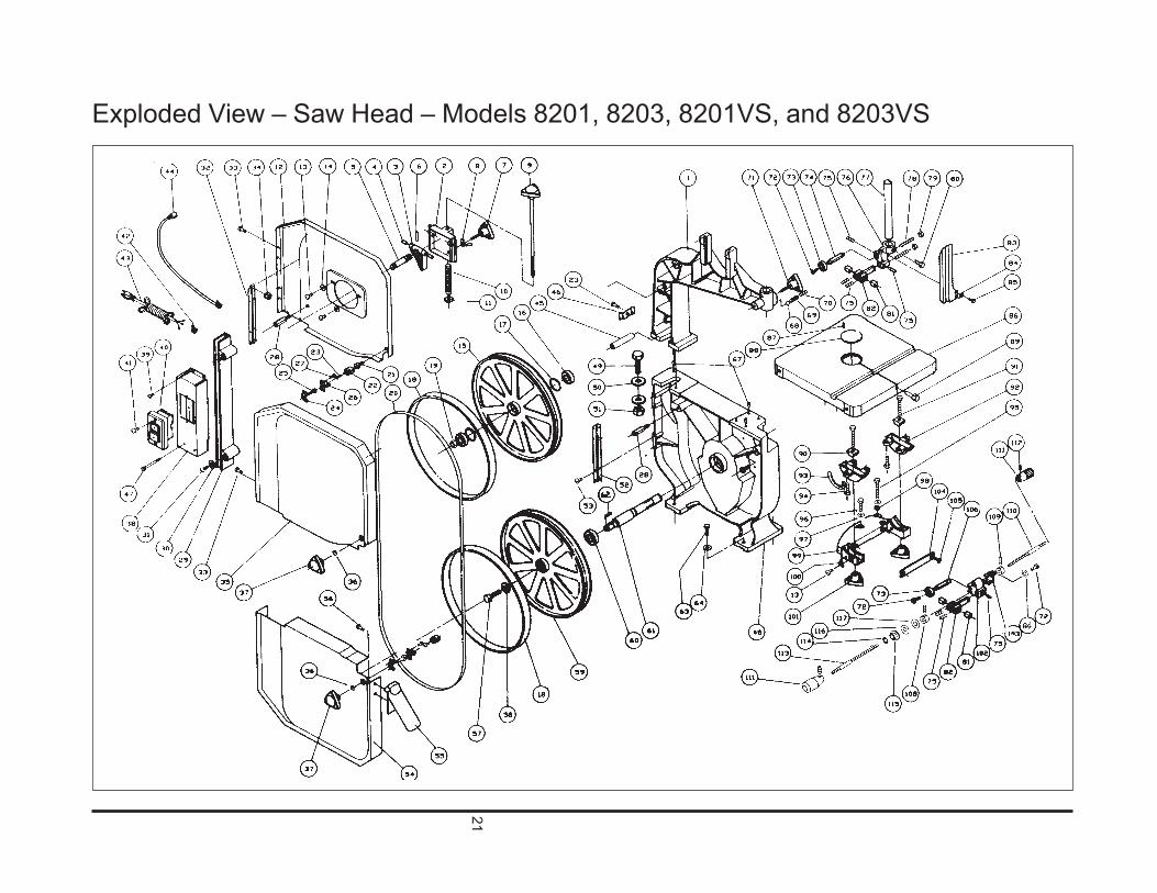
Exploded View – Saw Head – Models 8201, 8203, 8201VS, and 8203VS

22
Ref Part.No. Number Description Qty1 5782511 Upper Arm, Frame 12 5782521 Bracket, Upper Wheel Sliding 13 5782531 Hinge, Upper Wheel Shaft 14 5782541 Pin, Pivot 25 5782551 Shaft, Upper Wheel 16 5782561 Pin, Roll (4x16) 17 5782571 Knob, Blade Track Adjustment 1
(M8x55)8 5782581 Nut, Wing (M8x1.25) 19 5782591 Knob, Blade Tension Adjstmnt 110 5782611 Spring, Tension 111 5782621 Nut, Square 112 5782631 Guard, Upper Wheel (Inner) 113 5782641 Screw, Pan Head (M5x0l8x6) 314 5782651 Washer, Flat (M5x10) 215 5782661 Wheel, Upper 116 5782671 Bearing (6202Z) 217 5782681 Ring, Retaining (R-35) 218 5782691 Protector, Wheel 219 5782711 Nut, Hex (M12) 120 5782722 Blade, Saw, Metal Cutting 1
(92.5 x 0.025 x 14R)5782732 Blade, Saw, Wood Cutting 1
(92.5 x 0.025 x 6H)21 5782741 Bolt, Fixed 222 5782751 Catch 223 5782761 Screw, Pan Head (M5x0.8x12) 224 5782771 Bracket 225 5782781 Bolt, Hex Head (M8x1.25x16) 226 5782791 Lock, Male 427 5782811 Screw, Self Tapping (M4x0.7x8) 228 5782821 Stud 129 5782831 Guard, Blade 230 5782841 Retainer 231 5782851 Screw, Self Tapping (M3.5x12) 132 5782861 Hinge, Upper 1233 5782871 Screw, Pan Head (M5x0.8x8) 1234 5782881 Nut, Flange (M5x 0.8) 135 5782891 Guard, Upper Wheel (Outer) 136 5782911 Washer, Spring (M8) 237 5782921 Knob (M8x1.25) 138 5782931 Bracket, Switch 239 5782941 Screw, Self Tapping (M4x.7x10) 140 5782951 Switch 2
Ref Part.No. Number Description Qty41 5782961 Screw, Pan Head (M5x0.8x25) 242 5782971 Strain Relief (6W3-4R) 143 5782981 Cord, Power (110Volt, 1 phase) 1
5513899 Cord, Power (220 Volt, 3 phase)44 5782991 Cord, Power (Switch to Motor - 1
110 Volt, 1 phase)5513900 Cord, Power (Switch to Motor -
220 Volt, 3 phase)45 5783011 Bushing, Power Cord 146 5783021 Clip, Wire 147 5783031 Screw, Hex Head (M6x1x55) 148 5783041 Base 149 5783051 Bolt, Hex Head (M16x2x55) 250 5783061 Washer, Flat (M16x40) 151 5783071 Nut, Hex (M16) 152 5783081 Hinge (Lower) 453 5783091 Screw, Flat Head (M5x10) 154 5783111 Guard, Lower Wheel 155 5783121 Chute, Dust 256 5783131 Screw, Pan Head (M6x1x8) 157 5783141 Bolt, Hex Head (Left Hand)
(M8x1.25x15) 158 5783151 Washer, Flat 159 5783161 Wheel, Lower 260 5783171 Bearing (6204Z) 161 5783181 Shaft, Lower Wheel 1
(Metal Cutting Saw)5783191 Shaft, Lower Wheel 1
(Wood Cutting Saw)62 5783211 Key (5x5x20) 463 5783221 Bolt, Hex Head (M8x1.25x40) 464 5783231 Washer, Flat (M8x18) 465 - - - - - - - - - - - - -66 - - - - - - - - - - - - -67 5783241 Pin, Dowel 168 5783251 Ball, Steel (8 mm) 169 5783261 Spring 170 5783271 Screw, Set (M10x1.5x10) 171 5783281 Knob (M10x1.4x30) 272 5783291 Screw, Pan Head (M6x1x12) 173 5783311 Bearing (6200ZZ) 174 5783321 Sleeve, Upper Spacing 775 5783331 Screw, Set (M6x1x10) 176 5783341 Post, Upper Support Bracket 177 5783351 Post, Guide 2
Ref Part.No. Number Description Qty78 5783361 Screw, Micro Adjustment 2
(M8x1x40)79 5783371 Nut, Micro Adjustment 180 5783381 Screw, Hex Head (M6x1x10) 481 5783391 Blade Guide, Carbide 282 5783411 Bracket, Support 183 5783421 Guard, Upper Wheel Blade 184 5783431 Washer, Flat (M6x16) 285 5783441 Screw, Hex Head (M6x1x10) 186 5783451 Table 187 5783461 Pin, Roll (3x8) 188 5783471 Insert, Table 189 5783481 Pin, Table 290 5783491 Shoe, Trunnion Clamp 291 5783511 Bolt, Hex Head (M10x50) 292 5783521 Trunnion 193 5783531 Scale 694 5783541 Screw, Hex Head (M6x12) 195 5783551 Screw, Hex Head (M8x80) 296 5783561 Screw, Hex Head (M6x30) 297 5783571 Washer, Lock (M8) 198 5783581 Nut (M8x1.25) 199 5783591 Support, Bracket Trunnion 1100 5783611 Pointer 2101 5783621 Knob (M10x1.5) 2102 5783631 Post, Lower Support Bracket 1102 5783641 Block, Adjusting 1104 5783651 Plate, Guide 2105 5783661 Screw, Flat Head Socket 2
(M6x1x15)106 5783671 Sleeve, Spacing 2107 - - - - - - - - - - - - -108 5783681 Bushing, Setting 4109 5783691 Screw, Set (M5x0.8x5) 1110 5783711 Bar, Adjusting 2111 5783721 Handle 1112 - - - - - - - - - - - - -113 5783731 Bar, Adjusting 2114 5783741 Washer, Spring (M8) 2115 5783751 Nut, Flange (M8) 2116 5783761 Washer 2117 5783771 Spacer 1
Parts Listing – Saw Head – Models 8201, 8203, 8201VS, and 8203VS

23
Exploded View – Gearbox – Models 8201 and 8203

24
Ref Part.No. Number Description Qty1 5783831 Housing Gearbox 12 5629151 Bearing (6206ZZ) 13 9100441 Bearing (6200ZZ) 34 5783851 Bearing (6303ZZ) 15 5783861 Plug 26 5783871 Seal, Oil (30x7) 17 5783881 Seal, Oil (17x40x7) 18 5783891 Plug, Drain (1/8x28PT) 19 5783901 Plug (3/8x19PT) 110 5783911 Glass, Oil Level 111 5783921 Gear 112 5783931 Bearing (3206) 113 5783941 Ring, Internal Snap (R62) 114 5783951 Shaft (with gear) 1
Ref Part.No. Number Description Qty15 5783961 Key (5x5x18) 116 5783971 Bushing/Spacer 117 5783981 Gear 118 5783991 Shaft (with gear) 119 5784011 Key (5x5x40) 120 5513824 Pin, Parallel (5x20) 221 5784031 Key (7x7x20) 222 5784041 Ring, Retaining (S30) 323 5784051 Seal, Oil 124 5784061 Dog, Clutch 225 5784071 Pin, Roll (5x30) 226 5784081 Shaft, Clutch 127 5784091 Knob 128 5784111 Pulley 1
Ref Part.No. Number Description Qty29 5784121 Bushing 130 5513800 Cover, Bearing 131 5784141 Cover, Bearing 132 5784151 Cover, Bearing 133 5784161 Screw, Pan Head 9
(M5x0.8x8)34 5784171 Screw, Pan Head 8
(M6x1x10)35 5784181 Pulley, Gear Box 136 5784191 Screw, Set (M6x1x10) 237 5784211 V-Belt (A50) 138 5784221 V-Belt (A35) 139 5784231 Pin, Roll (4x16) 140 5518281 Oil, Gear Box 500cc (not 1
shown)
Parts Listing – Gearbox – Models 8201 and 8203

25
Exploded View – Gearbox – Models 8201VS and 8203VS

26
Parts Listing – Gearbox – Models 8201VS and 8203VS
Ref Part.No. Number Description Qty1 5513790 Housing Gearbox 12 5513791 Packing 13 5783861 Plug 24 5783911 Gauge, Oil Level 15 5513794 Shaft, Lower Wheel 16 5513795 O-Ring (P15) 17 5513796 O-ring (P24) 18 5513797 Block, Clutch 29 5513798 Gear (O) 110 5783971 Spacer 111 5513800 Cover, Bearing (O) 212 5513801 Pulley 113 5784121 Bushing 114 5784051 Seal, Oil (12x22x7) 115 5513804 Rod, Clutch 116 5513805 O-Ring (P9) 217 5784091 Knob (M10) 118 5513807 Gear, Helical (M) 1
Ref Part.No. Number Description Qty19 5783951 Shaft, Gear (M) 120 5783871 Cover, Oil Seal (30x7) 121 5784141 Cover, Bearing (M) 122 5783991 Shaft, Gear (I) 123 5783881 Seal, Oil (17x40x7) 124 5784151 Cover, Bearing (I) 125 5513814 Speed Changer, 1
Non-Step (Set)26 5513815 Belt, Synchronous 1
(V-Type)27 5513816 V-Belt (A51) 128 - - - - - - - - - - - - -29 - - - - - - - - - - - - -30 - - - - - - - - - - - - -31 9100441 Bearing (6200ZZ) 332 5783851 Bearing (6203ZZ) 133 5783931 Bearing (3206ZZ) 1
Ref Part.No. Number Description Qty34 5629151 Bearing (6206ZZ) 135 5783961 Key (5x5x18) 136 5784011 Key (5x5x40) 137 5784031 Key (7x7x20) 138 5513824 Pin, Parallel (5x20) 239 5784071 Pin, Spring (5x30) 240 5783941 Ring, Retaining (R62) 141 5784041 Ring, Stop (S30) 342 5513828 Bolt, Countersunk Head 3
(M5x10)43 5784161 Screw, Pan Head (M5x8) 9
44 5513830 Bolt, Pan Head (M6x16) 845 5513831 Bolt, Hex Head Socket 1
(M8x12)46 5513832 Screw, Set (M6x10) 247 5513833 Plug, Oil 1

27
Parts List – Optional Riser Block – All Models
Ref Part.No. Number Description Qty1 5784511 Block, Riser 12 5784521 Guard, Blade 13 5784531 Hook, Bracket 24 5784541 Screw, Self Tapping 45 5784551 Screw, Hex Head (M16x2x200) 16 5784561 Washer (M16) 17 5784571 Nut (M16) 18 5784581 Post, Guide 19 5784591 Guard, Upper Wheel Blade 110 5784611 Extender, Blade Guard 111 5784621 Bolt, Carriage (M8x15) 112 5784631 Washer (M8) 113 5782581 Nut, Wing (M8) 114 5784641 Blade, Saw (Metal Cutting) 1
5784681 Blade, Saw (Wood Cutting) 115 5784651 Pin, Dowel 216 5784661 Cord, Extension Power (1-Phase) 1
5784671 Cord, Extension Power (3-Phase) 1

28
Parts List – Optional Rip Fence – All Models
Ref Part.No. Number Description Qty1 5784811 Rail, Guide 22 5784821 Fence, Rip 13 5784831 Seat Assembly, Clamp 14 5784841 Clamp Rail 15 5784851 Plug (7/8) 46 5784861 Spacer 47 5784871 Knob 18 5784881 Bar, Adjusting 19 5784891 Nut (3/8x16UNC) 110 5784911 Handle 111 5784921 Screw, Socket Head Cap 4
(M8x30)12 5784931 Screw, Hex Head (M6x12) 213 5782981 Washer (M6) 2
5784941 Gauge Assembly, Miter 1(Not Shown)

29
Notes:


WMH Tool Group2420 Vantage Drive
Elgin, IL 60123Phone: 847-274-6848