
Standard Operating Procedure: Sampling Groundwater with ... · • A suspension line or tether...
17
Standard Operating Procedure: Sampling Groundwater with a HydraSleeve Copyright 2016 GeoInsight US Patent No. 6,481,300; No. 6,837,120 others pending
Transcript of Standard Operating Procedure: Sampling Groundwater with ... · • A suspension line or tether...
Standard Operating Procedure: Sampling Groundwater with a HydraSleeve
Copyright 2016 GeoInsight
US Patent No. 6,481,300; No. 6,837,120 others pending
This guide should be used in addition to field manuals and instructions appropriate to the chosen sampling device (i.e., HydraSleeve, SpeedBag or Super/Skinny Sleeve and W3 HybridSleeve).
Find the appropriate field manual and instructions on the HydraSleeve website at http:// www.hydrasleeve.com.
For more information about the HydraSleeve, or if you have questions, contact: GeoInsight, P.O. Box 1266, Mesilla Park, NM 88047 800-996-2225, [email protected].
Copyright, GeoInsight.
Table of Contents Introduction ..................................................................................................................................... 1
Applications of the HydraSleeve .......................................................................................................... 1
Description of the HydraSleeve ........................................................................................................... 3
Selecting the HydraSleeve Size to Meet Site-Specific Sampling Objectives................................... 4
HydraSleeve Deployment ..................................................................................................................... 5
Information Required Before Deploying a HydraSleeve ............................................................. 5
HydraSleeve Placement ............................................................................................................... 6
Procedures for Sampling with the HydraSleeve .................................................................................. 8
Measurement of Field Indicator Parameters .................................................................................. 11
Alternate Deployment Strategies ............................................................................................... 11
Post-Sampling Activities ..................................................................................................................... 14
References ..................................................................................................................................... 15
Standard Operating Procedure: Sampling Groundwater with the HydraSleeve (patents: 6,481,300; 6,837,120)
1 Copyright 2016 GeoInsight
Introduction
The HydraSleeve is classified as a no-purge (passive) grab sampling device, meaning that it is used to collect groundwater samples directly from the screened interval of a well without having to purge the well prior to sample collection. When it is used as described in this Standard Operating Procedure (SOP), the HydraSleeve causes no drawdown in the well (until the sample is withdrawn from the water column) and only minimal disturbance of the water column, because it has a very thin cross section and it displaces very little water (<100 ml) during deployment in the well. The HydraSleeve collects a sample from within the screen only. It excludes water from any other part of the water column in the well through the use of a self- sealing check valve at the top of the sampler. It is a single-use (disposable) sampler that is not intended for reuse, so there are no decontamination requirements for the sampler itself.
The use of no-purge sampling as a means of collecting representative groundwater samples depends on the natural movement of groundwater (under ambient hydraulic head) from the formation adjacent to the well screen through the screen. Robin and Gillham (1987) demonstrated the existence of a dynamic equilibrium between the water in a formation and the water in a well screen installed in that formation, which results in formation-quality water being available in the well screen for sampling at all times. No-purge sampling devices like the HydraSleeve collect this formation-quality water as the sample, under undisturbed (non- pumping) natural flow conditions. Samples collected in this manner generally provide more conservative (i.e., higher concentration) values than samples collected using well-volume purging, and values equivalent to samples collected using low-flow purging and sampling (Parsons, 2005).
Applications of the HydraSleeve
The HydraSleeve can be used to collect representative samples of groundwater for all analytes (volatile organic compounds [VOCs], semi-volatile organic compounds [SVOCs], common metals, trace metals, major cations and anions, dissolved gases, total dissolved solids, radionuclides, pesticides, PCBs, explosive compounds, and all other analytical parameters). Designs are available to collect samples from wells from 1” inside diameter and larger. The HydraSleeve can collect samples from wells of any yield, but it is especially well-suited to collecting samples from low-yield wells, where other sampling methods can’t be used reliably because their use results in dewatering of the well screen and alteration of sample chemistry (McAlary and Barker, 1987).
The HydraSleeve can collect samples from wells of any depth, and it can be used for single- event sampling or long-term groundwater monitoring programs. Because of its thin cross section and flexible construction, it can be used in narrow, constricted or damaged wells where rigid sampling devices may not fit. Using multiple HydraSleeves deployed in series along a single suspension line or tether, it is also possible to conduct in-well vertical profiling in wells in which contaminant concentrations are thought to be stratified.

Standard Operating Procedure: Sampling Groundwater with the HydraSleeve (patents: 6,481,300; 6,837,120)
2 Copyright 2016 GeoInsight
As with all groundwater sampling devices, HydraSleeves should not be used to collect groundwater samples from wells in which separate (non-aqueous) phase hydrocarbons (i.e., gasoline, diesel fuel or jet fuel) are present because of the possibility of incorporating some of the separate-phase hydrocarbon into the sample.
Standard Operating Procedure: Sampling Groundwater with the HydraSleeve (patents: 6,481,300; 6,837,120)
3 Copyright 2016 GeoInsight
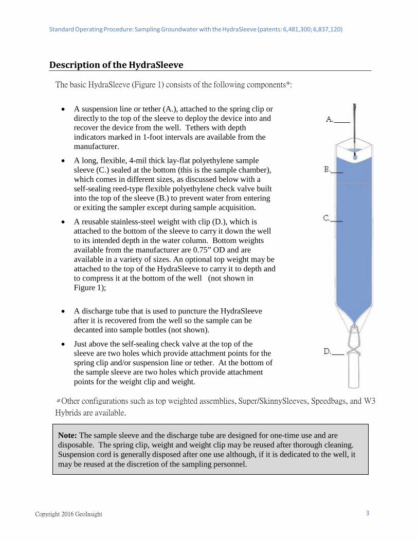
Description of the HydraSleeve
The basic HydraSleeve (Figure 1) consists of the following components*:
• A suspension line or tether (A.), attached to the spring clip ordirectly to the top of the sleeve to deploy the device into andrecover the device from the well. Tethers with depthindicators marked in 1-foot intervals are available from themanufacturer.
• A long, flexible, 4-mil thick lay-flat polyethylene samplesleeve (C.) sealed at the bottom (this is the sample chamber),which comes in different sizes, as discussed below with aself-sealing reed-type flexible polyethylene check valve builtinto the top of the sleeve (B.) to prevent water from enteringor exiting the sampler except during sample acquisition.
• A reusable stainless-steel weight with clip (D.), which isattached to the bottom of the sleeve to carry it down the wellto its intended depth in the water column. Bottom weightsavailable from the manufacturer are 0.75” OD and areavailable in a variety of sizes. An optional top weight may beattached to the top of the HydraSleeve to carry it to depth andto compress it at the bottom of the well (not shown inFigure 1);
• A discharge tube that is used to puncture the HydraSleeveafter it is recovered from the well so the sample can bedecanted into sample bottles (not shown).
• Just above the self-sealing check valve at the top of thesleeve are two holes which provide attachment points for thespring clip and/or suspension line or tether. At the bottom ofthe sample sleeve are two holes which provide attachmentpoints for the weight clip and weight.
* Other configurations such as top weighted assemblies, Super/SkinnySleeves, Speedbags, and W3
Hybrids are available.
Note: The sample sleeve and the discharge tube are designed for one-time use and are disposable. The spring clip, weight and weight clip may be reused after thorough cleaning. Suspension cord is generally disposed after one use although, if it is dedicated to the well, it may be reused at the discretion of the sampling personnel.
Standard Operating Procedure: Sampling Groundwater with the HydraSleeve (patents: 6,481,300; 6,837,120)
Copyright 2016 GeoInsight 4
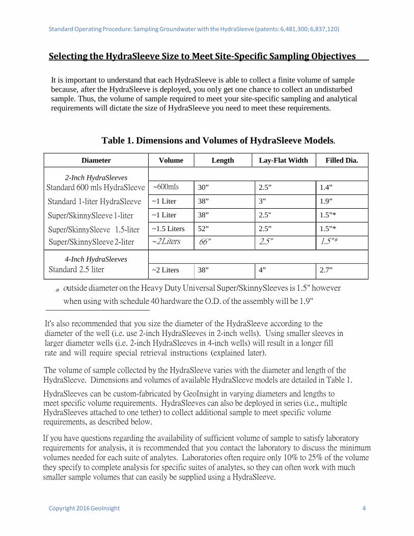
Selecting the HydraSleeve Size to Meet Site-Specific Sampling Objectives
It is important to understand that each HydraSleeve is able to collect a finite volume of sample because, after the HydraSleeve is deployed, you only get one chance to collect an undisturbed sample. Thus, the volume of sample required to meet your site-specific sampling and analytical requirements will dictate the size of HydraSleeve you need to meet these requirements.
Table 1. Dimensions and Volumes of HydraSleeve Models.
Diameter Volume Length Lay-Flat Width Filled Dia.
2-Inch HydraSleeves Standard 600 mls HydraSleeve
Standard 1-liter HydraSleeve
Super/SkinnySleeve 1-liter
Super/SkinnySleeve 1.5-liter
Super/SkinnySleeve 2-liter
~600mls 30” 2.5” 1.4”
~1 Liter 38” 3” 1.9”
~1 Liter 38” 2.5" 1.5”*
~1.5 Liters 52” 2.5” 1.5”* ~2 Liters 66" 2.5" 1.5"*
4-Inch HydraSleeves Standard 2.5 liter ~2 Liters 38” 4” 2.7”
* outside diameter on the Heavy Duty Universal Super/SkinnySleeves is 1.5" however
when using with schedule 40 hardware the O.D. of the assembly will be 1.9"
It's also recommended that you size the diameter of the HydraSleeve according to the diameter of the well (i.e. use 2-inch HydraSleeves in 2-inch wells). Using smaller sleeves in larger diameter wells (i.e. 2-inch HydraSleeves in 4-inch wells) will result in a longer fill rate and will require special retrieval instructions (explained later).
The volume of sample collected by the HydraSleeve varies with the diameter and length of the HydraSleeve. Dimensions and volumes of available HydraSleeve models are detailed in Table 1.
HydraSleeves can be custom-fabricated by GeoInsight in varying diameters and lengths to meet specific volume requirements. HydraSleeves can also be deployed in series (i.e., multiple HydraSleeves attached to one tether) to collect additional sample to meet specific volume requirements, as described below.
If you have questions regarding the availability of sufficient volume of sample to satisfy laboratory requirements for analysis, it is recommended that you contact the laboratory to discuss the minimum volumes needed for each suite of analytes. Laboratories often require only 10% to 25% of the volume they specify to complete analysis for specific suites of analytes, so they can often work with much smaller sample volumes that can easily be supplied using a HydraSleeve.
Standard Operating Procedure: Sampling Groundwater with the HydraSleeve (patents: 6,481,300; 6,837,120)
Copyright 2016 GeoInsight 5
HydraSleeve Deployment
Information Required Before Deploying a HydraSleeve
Before installing a HydraSleeve in any well, you will need to know the following:
• The inside diameter of the well
• The length of the well screen
• The water level in the well
• The position of the well screen in the well
• The total depth of the well
The inside diameter of the well is used to determine the appropriate HydraSleeve diameter for use in the well. The other information is used to determine the proper placement of the HydraSleeve in the well to collect a representative sample from the screen (see HydraSleeve Placement, below), and to determine the appropriate length of tether to attach to the HydraSleeve to deploy it at the appropriate position in the well.
Most of this information (with the exception of the water level) should be available from the well log; if not, it will have to be collected by some other means. The inside diameter of the well can be measured at the top of the well casing, and the total depth of the well can be measured by sounding the bottom of the well with a weighted tape. The position and length of the well screen may have to be determined using a down-hole camera if a well log is not available. The water level in the well can be measured using any commonly available water-level gauge.
Standard Operating Procedure: Sampling Groundwater with the HydraSleeve (patents: 6,481,300; 6,837,120)
Copyright 2016 GeoInsight 6
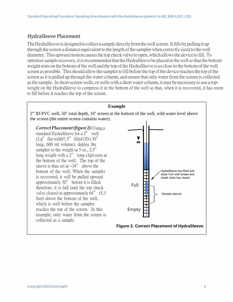
HydraSleeve Placement The HydraSleeve is designed to collect a sample directly from the well screen. It fills by pulling it up through the screen a distance equivalent to the length of the sampler when correctly sized to the well diameter. This upward motion causes the top check valve to open, which allows the device to fill. To optimize sample recovery, it is recommended that the HydraSleeve be placed in the well so that the bottom weight rests on the bottom of the well and the top of the HydraSleeve is as close to the bottom of the well screen as possible. This should allow the sampler to fill before the top of the device reaches the top of the screen as it is pulled up through the water column, and ensure that only water from the screen is collected as the sample. In short-screen wells, or wells with a short water column, it may be necessary to use a top- weight on the HydraSleeve to compress it in the bottom of the well so that, when it is recovered, it has room to fill before it reaches the top of the screen.
Example 2” ID PVC well, 50’ total depth, 10’ screen at the bottom of the well, with water level above the screen (the entire screen contains water).
Correct Placement (figure 2): Using astandard HydraSleeve for a 2” well (2.5” flat width/1.5” filled OD x 30” long, 600 ml volume), deploy the sampler so the weight (a 5 oz., 2.5” long weight with a 2” long clip) rests at the bottom of the well. The top of the sleeve is thus set at ~34” above the bottom of the well. When the sampler is recovered, it will be pulled upward approximately 30” before it is filled; therefore, it is full (and the top check valve closes) at approximately 64” (5.3 feet) above the bottom of the well, which is well before the sampler reaches the top of the screen. In this example, only water from the screen is collected as a sample.
Figure 2. Correct Placement of HydraSleeve.
Standard Operating Procedure: Sampling Groundwater with the HydraSleeve (patents: 6,481,300; 6,837,120)
Copyright 2016 GeoInsight 7
This example illustrates one of many types of HydraSleeve placements. More complex placements are discussed in a later section.
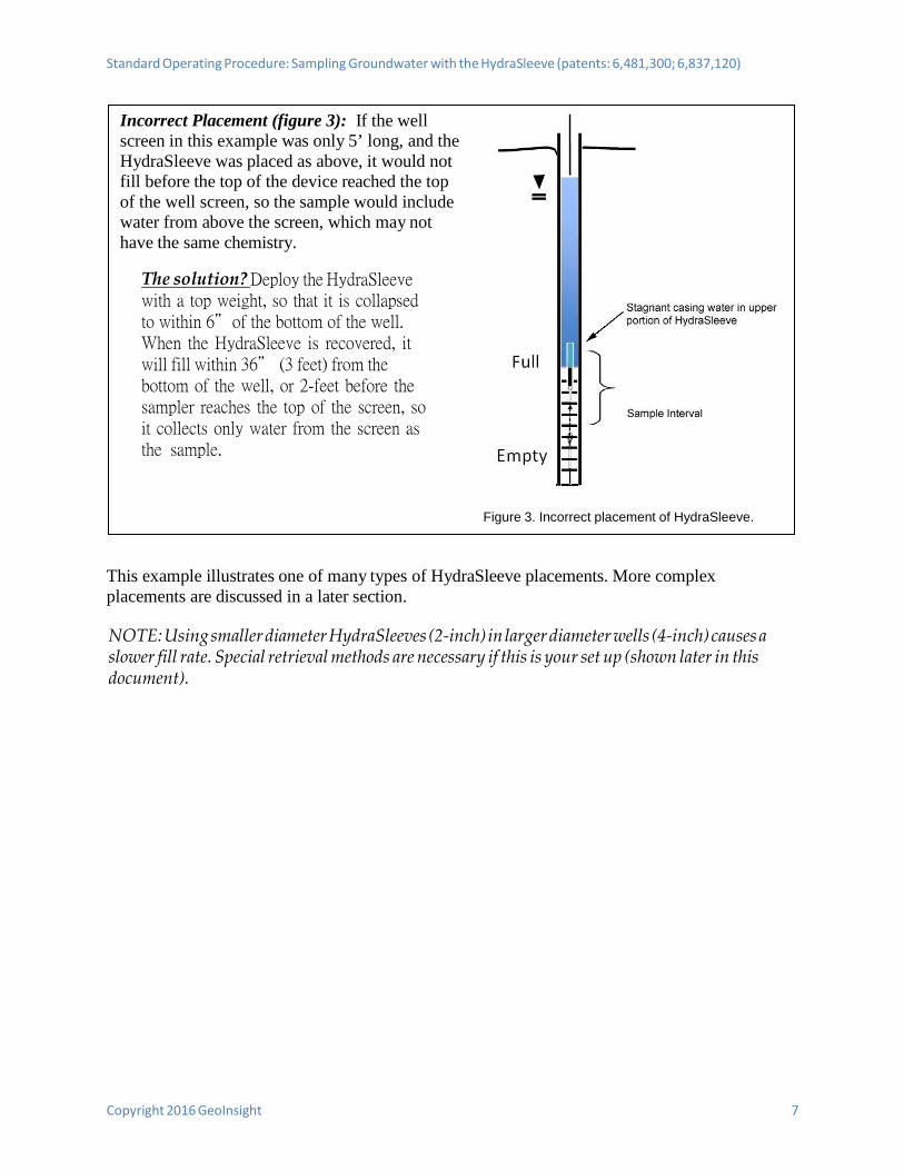
NOTE: Using smaller diameter HydraSleeves (2-inch) in larger diameter wells (4-inch) causes a slower fill rate. Special retrieval methods are necessary if this is your set up (shown later in this document).
Incorrect Placement (figure 3): If the well screen in this example was only 5’ long, and the HydraSleeve was placed as above, it would not fill before the top of the device reached the top of the well screen, so the sample would include water from above the screen, which may not have the same chemistry.
The solution? Deploy the HydraSleevewith a top weight, so that it is collapsed to within 6”of the bottom of the well. When the HydraSleeve is recovered, it will fill within 36” (3 feet) from the bottom of the well, or 2-feet before the sampler reaches the top of the screen, so it collects only water from the screen as the sample.
Figure 3. Incorrect placement of HydraSleeve.
Standard Operating Procedure: Sampling Groundwater with the HydraSleeve (patents: 6,481,300; 6,837,120)
Copyright 2016 GeoInsight 8
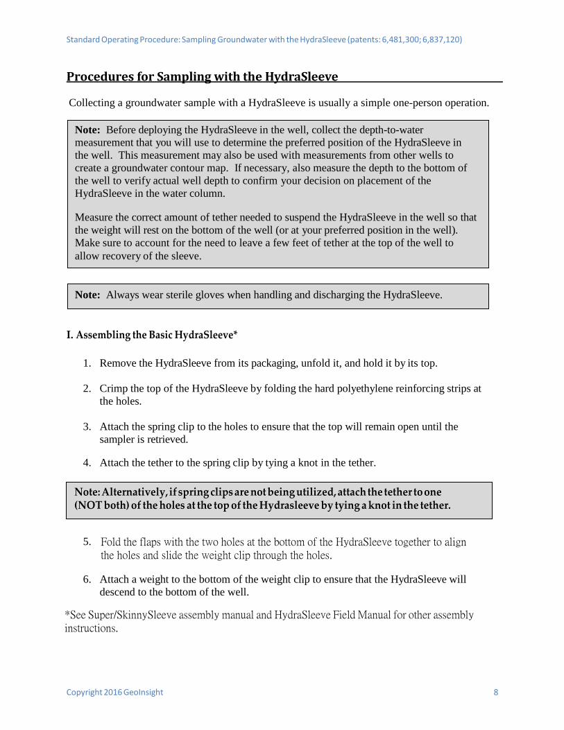
Procedures for Sampling with the HydraSleeve
Collecting a groundwater sample with a HydraSleeve is usually a simple one-person operation.
I. Assembling the Basic HydraSleeve*
1. Remove the HydraSleeve from its packaging, unfold it, and hold it by its top.
2. Crimp the top of the HydraSleeve by folding the hard polyethylene reinforcing strips atthe holes.
3. Attach the spring clip to the holes to ensure that the top will remain open until thesampler is retrieved.
4. Attach the tether to the spring clip by tying a knot in the tether.
5. Fold the flaps with the two holes at the bottom of the HydraSleeve together to alignthe holes and slide the weight clip through the holes.
6. Attach a weight to the bottom of the weight clip to ensure that the HydraSleeve willdescend to the bottom of the well.
*See Super/SkinnySleeve assembly manual and HydraSleeve Field Manual for other assemblyinstructions.
Note: Alternatively, if spring clips are not being utilized, attach the tether to one (NOT both) of the holes at the top of the Hydrasleeve by tying a knot in the tether.
Note: Always wear sterile gloves when handling and discharging the HydraSleeve.
Note: Before deploying the HydraSleeve in the well, collect the depth-to-water measurement that you will use to determine the preferred position of the HydraSleeve in the well. This measurement may also be used with measurements from other wells to create a groundwater contour map. If necessary, also measure the depth to the bottom of the well to verify actual well depth to confirm your decision on placement of the HydraSleeve in the water column.
Measure the correct amount of tether needed to suspend the HydraSleeve in the well so that the weight will rest on the bottom of the well (or at your preferred position in the well). Make sure to account for the need to leave a few feet of tether at the top of the well to allow recovery of the sleeve.
Standard Operating Procedure: Sampling Groundwater with the HydraSleeve (patents: 6,481,300; 6,837,120)
II. Deploying the HydraSleeve
1. Using the tether, carefully lower the HydraSleeve to the bottom of the well, or to yourpreferred depth in the water column
During installation, hydrostatic pressure in the water column will keep the self-sealingcheck valve at the top of the HydraSleeve closed, and ensure that it retains its flat, emptyprofile for an indefinite period prior to recovery.
2. Secure the tether at the top of the well by placing the well cap on the top of the wellcasing and over the tether.
III. Equilibrating the Well
The equilibration time is the time it takes for conditions in the water column (primarily flow dynamics and contaminant distribution) to restabilize after vertical mixing occurs (caused by installation of a sampling device in the well).
• Situation: The HydraSleeve is deployed for the first time or for only one time in a wellThe basic HydraSleeve is very thin in cross section and displaces very little water(<100 ml) during deployment so, unlike most other sampling devices, it does notdisturb the water column to the point at which long equilibration times arenecessary to ensure recovery of a representative sample.
In some cases, like when useing the SpeedBags, the HydraSleeve can berecovered immediately (with no equilibration time) or within a few hours. Inregulatory jurisdictions that impose specific requirements for equilibration timesprior to recovery of no-purge sampling devices, these requirements should befollowed.
NOTE: If using top weights additional equilibration time is needed to allow the top weight time to compress the HydraSleeve into the bottom of the well.
• Situation: The HydraSleeve is being deployed for recovery during a future samplingevent.In periodic (i.e., quarterly, semi-annual, or annual) sampling programs, the samplerfor the current sampling event can be recovered and a new sampler (for the nextsampling event) deployed immediately thereafter, so the new sampler remains inthe well until the next sampling event.
9 Copyright 2016 GeoInsight
Note: Alternatively, you can tie the tether to a hook on the bottom of the well cap (you will need to leave a few inches of slack in the line to avoid pulling the sampler up as the cap is removed at the next sampling event).
Note: Make sure that it is not pulled upward at any time during its descent. If the HydraSleeve is pulled upward at a rate greater than 0.5’/second at any time prior to recovery, the top check valve will open and water will enter the HydraSleeve prematurely.
Standard Operating Procedure: Sampling Groundwater with the HydraSleeve (patents: 6,481,300; 6,837,120)
Copyright 2016 GeoInsight 10
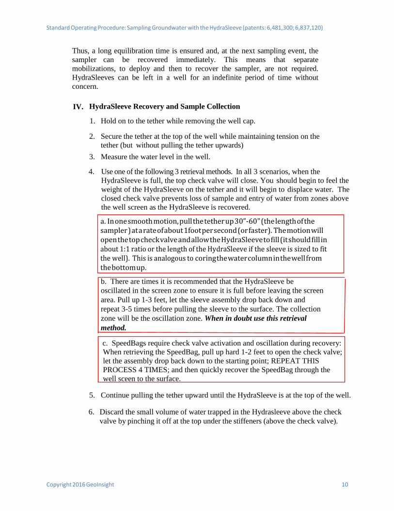
Thus, a long equilibration time is ensured and, at the next sampling event, the sampler can be recovered immediately. This means that separate mobilizations, to deploy and then to recover the sampler, are not required. HydraSleeves can be left in a well for an indefinite period of time without concern.
IV. HydraSleeve Recovery and Sample Collection
1. Hold on to the tether while removing the well cap.
2. Secure the tether at the top of the well while maintaining tension on thetether (but without pulling the tether upwards)
3. Measure the water level in the well.
4. Use one of the following 3 retrieval methods. In all 3 scenarios, when theHydraSleeve is full, the top check valve will close. You should begin to feel theweight of the HydraSleeve on the tether and it will begin to displace water. Theclosed check valve prevents loss of sample and entry of water from zones abovethe well screen as the HydraSleeve is recovered.
5. Continue pulling the tether upward until the HydraSleeve is at the top of the well.
6. Discard the small volume of water trapped in the Hydrasleeve above the checkvalve by pinching it off at the top under the stiffeners (above the check valve).
c. SpeedBags require check valve activation and oscillation during recovery:When retrieving the SpeedBag, pull up hard 1-2 feet to open the check valve; let the assembly drop back down to the starting point; REPEAT THIS PROCESS 4 TIMES; and then quickly recover the SpeedBag through the well sceen to the surface.
b. There are times it is recommended that the HydraSleeve beoscillated in the screen zone to ensure it is full before leaving the screen area. Pull up 1-3 feet, let the sleeve assembly drop back down and repeat 3-5 times before pulling the sleeve to the surface. The collection zone will be the oscillation zone. When in doubt use this retrieval method.
a. In one smooth motion, pull the tether up 30”-60" (the length of thesampler ) at a rate of about 1foot per second (or faster). The motion will open the top check valve and allow the HydraSleeve to fill (it should fill in about 1:1 ratio or the length of the HydraSleeve if the sleeve is sized to fit the well). This is analogous to coring the water column in the well from the bottom up.
Standard Operating Procedure: Sampling Groundwater with the HydraSleeve (patents: 6,481,300; 6,837,120)
Copyright 2016 GeoInsight 11
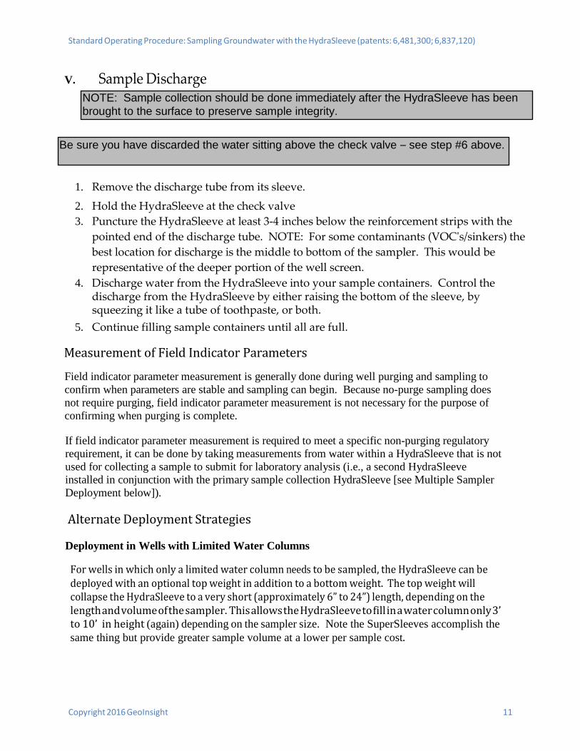
V. Sample Discharge
1. Remove the discharge tube from its sleeve.
2. Hold the HydraSleeve at the check valve3. Puncture the HydraSleeve at least 3-4 inches below the reinforcement strips with the
pointed end of the discharge tube. NOTE: For some contaminants (VOC's/sinkers) thebest location for discharge is the middle to bottom of the sampler. This would berepresentative of the deeper portion of the well screen.
4. Discharge water from the HydraSleeve into your sample containers. Control thedischarge from the HydraSleeve by either raising the bottom of the sleeve, bysqueezing it like a tube of toothpaste, or both.
5. Continue filling sample containers until all are full.
Measurement of Field Indicator Parameters
Field indicator parameter measurement is generally done during well purging and sampling to confirm when parameters are stable and sampling can begin. Because no-purge sampling does not require purging, field indicator parameter measurement is not necessary for the purpose of confirming when purging is complete.
If field indicator parameter measurement is required to meet a specific non-purging regulatory requirement, it can be done by taking measurements from water within a HydraSleeve that is not used for collecting a sample to submit for laboratory analysis (i.e., a second HydraSleeve installed in conjunction with the primary sample collection HydraSleeve [see Multiple Sampler Deployment below]).
Alternate Deployment Strategies
Deployment in Wells with Limited Water Columns
For wells in which only a limited water column needs to be sampled, the HydraSleeve can be deployed with an optional top weight in addition to a bottom weight. The top weight will collapse the HydraSleeve to a very short (approximately 6” to 24”) length, depending on the length and volume of the sampler. This allows the HydraSleeve to fill in a water column only 3’ to 10’ in height (again) depending on the sampler size. Note the SuperSleeves accomplish the same thing but provide greater sample volume at a lower per sample cost.
Be sure you have discarded the water sitting above the check valve – see step #6 above.
NOTE: Sample collection should be done immediately after the HydraSleeve has been brought to the surface to preserve sample integrity.
Standard Operating Procedure: Sampling Groundwater with the HydraSleeve (patents: 6,481,300; 6,837,120)
Copyright 20106 GeoInsight 12
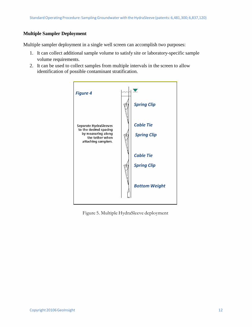
Multiple Sampler Deployment
Multiple sampler deployment in a single well screen can accomplish two purposes:
1. It can collect additional sample volume to satisfy site or laboratory-specific samplevolume requirements.
2. It can be used to collect samples from multiple intervals in the screen to allowidentification of possible contaminant stratification.
Figure 5. Multiple HydraSleeve deployment
Figure 4
Spring Clip
Cable Tie
Spring Clip
Cable Tie
Spring Clip
Bottom Weight
Copyright 2016 GeoInsight 13
Standard Operating Procedure: Sampling Groundwater with the HydraSleeve (patents: 6,481,300; 6,837,120)
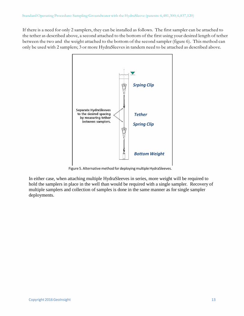
If there is a need for only 2 samplers, they can be installed as follows. The first sampler can be attached to the tether as described above, a second attached to the bottom of the first using your desired length of tether between the two and the weight attached to the bottom of the second sampler (figure 6). This method can only be used with 2 samplers; 3 or more HydraSleeves in tandem need to be attached as described above.
Figure 5. Alternative method for deploying multiple HydraSleeves.
In either case, when attaching multiple HydraSleeves in series, more weight will be required to hold the samplers in place in the well than would be required with a single sampler. Recovery of multiple samplers and collection of samples is done in the same manner as for single sampler deployments.
Srping Clip
Tether
Spring Clip
Bottom Weight
Copyright 2016 GeoInsight 14
Standard Operating Procedure: Sampling Groundwater with the HydraSleeve (patents: 6,481,300; 6,837,120)
Post-Sampling Activities
The recovered HydraSleeve and the sample discharge tubing should be disposed as per the solid waste management plan for the site. To prepare for the next sampling event, a new HydraSleeve can be deployed in the well (as described previously) and left in the well until the next sampling event, at which time it can be recovered.
The weight and weight clip can be reused on this sampler after they have been thoroughly cleaned as per the site equipment decontamination plan. The tether may be dedicated to the well and reused or discarded at the discretion of sampling personnel.
Copyright 2016 GeoInsight 15
Standard Operating Procedure: Sampling Groundwater with the HydraSleeve (patents: 6,481,300; 6,837,120)
References
McAlary, T. A. and J. F. Barker, 1987, Volatilization Losses of Organics During groundwater Sampling From Low-Permeability Materials, groundwater Monitoring Review, Vol. 7, No. 4, pp. 63-68
Parsons, 2005, Results Report for the Demonstration of No-Purge groundwater Sampling Devices at Former McClellan Air Force Base, California; Contract F44650-99-D-0005, Delivery Order DKO1, U.S. Army Corps of Engineers (Omaha District), U.S. Air Force Center for Environmental Excellence, and U.S. Air Force Real Property Agency
Robin, M. J. L. and R. W. Gillham, 1987, Field Evaluation of Well Purging Procedures, groundwater Monitoring Review, Vol. 7, No. 4, pp. 85-93


![Tether anthony[1]](https://static.fdocuments.us/doc/165x107/557c7d36d8b42a494c8b5161/tether-anthony1.jpg)