
Standard Missile-2 Block IVA Analysis and Test · Standard Missile-2 Block IVA Analysis and Test...
12
248 JOHNS HOPKINS APL TECHNICAL DIGEST, VOLUME 22, NUMBER 3 (2001) S Standard Missile-2 Block IVA Analysis and Test Bruce E. Kuehne, Robert A. Patterson, John E. Schmiedeskamp, Gregg A. Harrison, Matthew E. Antonicelli, Linda M. Howser, and Steven A. Lutz tandard Missile-2 Block IVA is being developed to provide a Theater Ballistic Missile Defense capability for the Navy. The need to achieve high lethality against tactical bal- listic missile threats has dictated a Block IVA missile configuration embodying low guid- ance noise, rapid missile response time, and a forward-looking fuze concept. As Technical Direction Agent to the Navy for Standard Missile, APL provided top-level requirements for the Block IVA Program and continues to provide an independent assessment of the Block IVA design through analysis, simulation, and testing. Three specific areas of APL involvement exemplify contributions to the Block IVA Program: (1) system-level simula- tion and analysis, (2) guidance section hardware and software testing, and (3) infrared seeker dome testing. Improvements developed as a result of these systems engineering activ- ities are key to ensuring that the Block IVA design meets its overall system requirements. INTRODUCTION The Standard Missile-2 (SM-2) Block IVA design will provide the Navy Surface Fleet with a Theater Bal- listic Missile Defense (TBMD) capability while retain- ing capability against anti-air warfare cruise missile threats. Aegis ships equipped with Block IVA rounds and associated Aegis Weapon System radar and pro- cessing system upgrades will provide defense of debarka- tion ports, critical coastal assets, and population centers against short- and intermediate-range tactical ballistic missiles. The Block IVA missile, which will intercept the threat under endo-atmospheric conditions, involves evo- lutionary changes to the existing Block IV anti-air war- fare design. The need to achieve high lethality against tactical ballistic missile threats has dictated a Block IVA configuration that embodies low guidance noise and rapid missile response, as well as a forward-looking fuzing con- cept that can place missile warhead fragments on the desired vulnerable area of a high-speed tactical ballistic missile threat. For these characteristics to be achieved, the Block IVA guidance section includes a new side- mounted imaging infrared (IR) seeker that provides low- noise target centroid angle measurements for guidance and information for calculating the warhead fuzing solu- tion. The design also includes a new forward-looking active radio-frequency (RF) adjunct sensor (RFAS) that provides additional measurements that are required for fuzing. Other guidance section improvements include an upgraded digital signal processor to provide adequate computing throughput for a new highly responsive multi- variable autopilot, an improved terminal guidance algo- rithm, and the fuzing algorithm. The Block IVA missile
Transcript of Standard Missile-2 Block IVA Analysis and Test · Standard Missile-2 Block IVA Analysis and Test...
248 JOHNSHOPKINSAPLTECHNICALDIGEST,VOLUME22,NUMBER3(2001)
B. E. KUEHNE et al.
S
StandardMissile-2BlockIVAAnalysisandTest
Bruce E. Kuehne, Robert A. Patterson, John E. Schmiedeskamp, Gregg A. Harrison,Matthew E. Antonicelli, Linda M. Howser, and Steven A. Lutz
tandardMissile-2BlockIVAisbeingdevelopedtoprovideaTheaterBallisticMissileDefensecapabilityfortheNavy.Theneedtoachievehighlethalityagainsttacticalbal-listicmissilethreatshasdictatedaBlockIVAmissileconfigurationembodyinglowguid-ancenoise,rapidmissileresponsetime,andaforward-lookingfuzeconcept.AsTechnicalDirectionAgenttotheNavyforStandardMissile,APLprovidedtop-levelrequirementsfortheBlockIVAProgramandcontinuestoprovideanindependentassessmentoftheBlockIVAdesignthroughanalysis,simulation,andtesting.ThreespecificareasofAPLinvolvementexemplifycontributionstotheBlockIVAProgram:(1)system-levelsimula-tionandanalysis, (2)guidance sectionhardwareand software testing,and(3) infraredseekerdometesting.Improvementsdevelopedasaresultofthesesystemsengineeringactiv-itiesarekeytoensuringthattheBlockIVAdesignmeetsitsoverallsystemrequirements.
INTRODUCTIONThe Standard Missile-2 (SM-2) Block IVA design
willprovidetheNavySurfaceFleetwithaTheaterBal-listicMissileDefense(TBMD)capabilitywhileretain-ing capability against anti-air warfare cruise missilethreats. Aegis ships equipped with Block IVA roundsand associated Aegis Weapon System radar and pro-cessingsystemupgradeswillprovidedefenseofdebarka-tionports,criticalcoastalassets,andpopulationcentersagainst short-and intermediate-range tacticalballisticmissiles.
The Block IVA missile, which will intercept thethreatunderendo-atmosphericconditions,involvesevo-lutionarychangestotheexistingBlockIVanti-airwar-faredesign.Theneed toachievehigh lethality againsttacticalballisticmissilethreatshasdictatedaBlockIVAconfigurationthatembodieslowguidancenoiseandrapid
missileresponse,aswellasaforward-lookingfuzingcon-cept that can place missile warhead fragments on thedesiredvulnerableareaofahigh-speedtacticalballisticmissile threat.For these characteristics tobeachieved,the Block IVA guidance section includes a new side-mountedimaginginfrared(IR)seekerthatprovideslow-noise target centroid angle measurements for guidanceandinformationforcalculatingthewarheadfuzingsolu-tion. The design also includes a new forward-lookingactiveradio-frequency(RF)adjunctsensor(RFAS)thatprovides additional measurements that are required forfuzing. Other guidance section improvements includeanupgradeddigitalsignalprocessortoprovideadequatecomputingthroughputforanewhighlyresponsivemulti-variableautopilot,animprovedterminalguidancealgo-rithm,andthefuzingalgorithm.TheBlockIVAmissile
JOHNSHOPKINSAPLTECHNICALDIGEST,VOLUME22,NUMBER3(2001) 249
STANDARD MISSILE-2 BLOCK IVA ANALYSIS AND TEST
isbeingdevelopedbyRaytheonCompanyunder spon-sorshipof theNavyProgramExecutiveOffice,TheaterSurfaceCombatants(PEO(TSC)).
Forinterceptsagainsttacticalballisticmissilethreats,the Block IVA missile is command-guided (via anuplinkfromtheAegisship)duringtheearlypartofitsflight.As themissile approaches the target, the shipsuppliesdesignationinformationthatthemissileusesto point its IR seeker toward the target. The missileinitiatesIRtrackandterminalguidanceonthedesig-natedobject,withtheIRseekerprovidingtargetstatemeasurementsforuseinanoptimalguidancelaw.Asthemissilecontinuestocloseonthetarget, themis-sile-to-target rangeeventuallybecomes smallenoughthatthetargetimageisresolved(i.e.,coversmultiplefocalplanepixels) in the IR sensorfieldofview.Ataboutthesametime,theRFASisalsopointedatthetargetandbeginstoprovidetargetinformation.TheseIRandRFASdataareusedinaforward-lookingfuze(FLF)processtodeterminethelocationofthetargetpayload relative to the interceptor missile warhead.Themissileusesthispayloadlocationestimatetocom-pute theburst timerequiredtocause theBlockIVAwarheadfragmentstostrikethetargetpayload(intheevent that body-to-body impact of the target is notachieved).
As SM Technical Direction Agent for the Navy,APL is providing an independent assessment of theBlockIVAdesignfromasystemsengineeringperspec-tive. In this role,APLprovided requirements defini-tionaswellaspreliminarydesignconceptdevelopmentandevaluationearlyintheBlockIVAProgram.Asthedesign matured, APL efforts shifted to evaluation ofthecontractor’sdetaileddesign.Thesedesignevalua-tionsinvolvehigh-fidelitysimulationstudiesandcom-plementary analysis efforts as well as hardware andsoftwaretesting.
Much of the focus of these efforts is on evaluatingthe operation of the Block IVA design as an overallsystem, providing confidence that all elements of themissileguidance,control,navigation,andfuzingsubsys-temsoperateinthemannerrequiredtoallowthemissiletodefeatthetacticalballisticmissilethreat.APL’shigh-fidelityBlockIVAsystemsimulation,whichmodelsallof the missile sensors, the associated processing algo-rithms,andshipsysteminterfaces,isusedtoensurethatthe functional design meets its requirements. Testingin the APL Guidance System Evaluation Laboratory(GSEL)providesconfidenceinthesesimulationresultsbyensuringthattheintegratedhardwareandsoftwaredesigns,asimplementedintheactualmissileguidancesection, not only meet their design requirements butalso will operate as desired in off-nominal and con-tingencyenvironments.Inaddition,earlydesignstud-ies indicated that survival of the side-mounted IRseeker dome in the high-velocity (and hence, high
aerothermal heating) environment associated withBlockIVAflightwasapotentialriskareaforthepro-gram.Hence,APLinitiatedanalysisandtestactivitiestoquantifytheIRdomeaerothermalenvironment,torelatethesethermalcharacteristicstothedomesurvivalmargin,andtoverifytheanalysisthroughwindtunneltesting of prototype dome assemblies. Examples fromthese analysis and test activities are described in theremainderofthisarticle.
SYSTEM MODELING AND SIMULATION ANALYSIS
APLhasalongheritageofcontributionsintheareaofSMsimulationdevelopmentandanalysis,beginninginthemid-1960swithsimplifiedanalogmodelsoftheSM-1 Block V design. As computer and workstationprocessing speeds increased, more capable all-digitalsimulationsweredeveloped, leadingtoahigh-fidelity,stochastic, six-degree-of-freedom (6-DOF) simulationof the SM-2 Block IV missile in the late 1980s. Thissimulation includedhighlydetailedmodelsof the fastFouriertransform–basedmissilereceiverandradardataprocessingaswellasahigh-fidelitymodelof the low-altitude multipath environment. The family of APLSMsimulationsismaintainedinaclassifiedworkstationenvironmentandcontrolledunder rigorousconfigura-tionmanagementprocedures.
Early Navy TBMD concept definition studies wereperformedinthemid-1990susingamodifiedversionoftheBlockIV6-DOFsimulation.AnIRseekermodel,developedundertheHighPerformanceIRSeekerPro-gram, was integrated into the simulation along withother guidance and control modifications to supportearly design studies. This simulation also served asthe basis for a representation of the Block IVA RiskReductionFlightDemonstration(RRFD)missilecon-figuration. The RRFD Program demonstrated the fea-sibility of using the Block IVA IR seeker for TBMDmissionsbyconductingasuccessfulinterceptofaLancetacticalballisticmissile target atWhiteSandsMissileRange(WSMR)inJanuary1997.
Eventually, the Block IV/IVA simulation was splitintotwoindependentsimulationstofacilitateefficientdevelopment of both variants. The Block IV modelscommontotheBlockIVAconfigurationwereretainedalong with Block IVA–specific models. Selected sub-system models developed, verified, and validated aspart of the RRFD Program were then integrated intotheBlock IVAversionof the simulation tocreateanofficial Block IVA 6-DOF simulation. Upgrades weresubsequently made to enhance the detailed modelingof the tactical ballistic missile target kinematics andsignatures (both IR and RF), the IR seeker platformand sensor, the RFAS sensor, the Aegis SPY-1 radarand weapon control system (including the target
250 JOHNSHOPKINSAPLTECHNICALDIGEST,VOLUME22,NUMBER3(2001)
B. E. KUEHNE et al.
designationprocess),andtheFLFalgorithm.Aninter-facetoahigh-fidelityimage-basedmodeloftheBlockIVA IR seeker was also included. (The image-basedseekersimulationisdiscussedindetail inSteinbergetal.,thisissue.)AlthoughtheexistingAPLBlockIVAsimulationincludeskeyelementsoftheAegisWeaponSystem(including launchscheduling,midcourseguid-ance,missile/targettrackfiltering,anduplink/downlinkoperation), efforts arealsounderway to integrate themissile6-DOFsimulationmodelintoacomprehensiveAreaTBMDsystemsimulationthatincludesadetailedSPY-1 FirmTrack model and representations of otherweaponsystemfunctions.
TheBlockIVAsimulationmodelhasbeenacriticaltoolinnumerousBlockIVAstudiesperformedbyAPL,startingwiththedevelopmentofBlockIVArequirementsandcontinuingwithevaluationsofthecontractor’sguid-ance,autopilot,and fuzingdesigns.Severalexamplesofsuchstudiesarediscussedinthefollowingsections.
Top-Level Requirements DevelopmentAPLperformedearlyBlockIVAsimulationstudies
to support the development of the Block IVA TopLevelRequirements(TLR)document.TheTLRspeci-fiedtherequirementsagainstwhichtheBlockIVAmis-silewas tobedesignedandevaluated.Afundamentalrequirement for the system is the defended footprint,which is the area on the surface of the Earth to bedefendedbytheBlockIVAmissile.Thedefendedfoot-printisdefinedintermsofmaximumdownrange,cross-range,andbackrangetargetimpactpointsforwhichtheBlock IVA missile must provide intercept capability.Themissile is requiredtoprovideat leastaminimumaverageprobabilityofkill(PK)forinterceptsabovethisdefended footprint.APLwas instrumental indefiningtheengagementspacerequirementsoverwhichthisPKrequirementmustbesatisfied.
Indefiningtheengagementspacerequirement,APLworkedtostrikeanacceptablebalancebetweenmissileandshipboardsystemperformancerequirements.FromanoverallAreaTBMDsystemstandpoint(i.e.,includ-ingbothBlockIVAmissileandAegisshipsystemper-formance), the fundamental top-level requirement isprobabilityofnegation(PN).PN is a functionofboththe probability that the Aegis Weapon System pro-vides engagement support (PES) and the probabilitythat the interceptor kills the target, given the Aegissystemsupport(PK).Furthermore,PKisafunctionofthetargetinterceptaltitude.Hence,theengagementspacerequirement is determined by specifying the perfor-mance of the missile as a function of altitude (i.e.,(PK(alt)) and specifying the probability density func-tion of allowable intercept points (i.e., pdf(alt)). Themeaninterceptaltitude(asafunctionoftheinterceptdownrange)isdictatedbytheAegislaunchscheduling
policy, with the launch scheduler designed to ensurethatPKismaximized.
Althoughthedistributionofinterceptaltitudes(i.e.,theengagementspacerequirement)reflectsatrade-offbetweenmissile and ship systemperformance require-ments,thisdistributionisalmostentirelycontrolledbytheaccuracywithwhichtheshipcanschedulelaunches.Ifvariationsininterceptaltitudearetobekeptlow,thetargetmustbeintrackforafairlylongtimetoensurethattheSPYtrackfilterprocesshassettledbeforethetargettrackisusedinthemissilelaunchschedulingpro-cess.Theneed for a longprelaunch target track timewould result in a requirement for ahigh level of shipradar resources to support any given engagement. Ontheotherhand,iflimitedshipresourcesdictateashorterprelaunch track time and hence a broader interceptaltitude distribution, the missile must have good per-formanceoverawide rangeof interceptaltitudesandhence over a wide range of intercept conditions (i.e.,velocity,dynamicpressure,andtargetIRintensity).
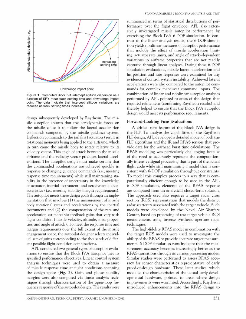
To determine the proper balance between ship andmissileconstraints,APLconductedacovarianceanaly-sistorelatethedistributionofinterceptaltitudestothelengthoftheshipradartracksettlingtime.Thelengthof the required track settling time isdirectly related totheacquisitionrangeoftheradar.Anexampleresultisshown inFig. 1,whichplots the standarddeviationofaltitude variations alt for various radar settling times.To verify the results of this covariance analysis, theBlockIVA6-DOFsimulationwasusedtoinvestigatetheinterceptaltitudedistributionatthemaximumrequireddownrangeimpactpoint.Targetacquisitionbytheshipradarwasforcedtooccurattheappropriatetimetoallowthedesiredamountoftracksettlingbeforetheintercep-torlaunchwasscheduled.Asetof200MonteCarlosim-ulationrunswasperformed.Thedistributioncomputedthroughthis6-DOFsimulationstudywasnearlythesameasthatpredictedbythecovarianceanalysis.Inaddition,the6-DOFsimulationwasusedtoestimatethemissilePKasafunctionofaltitude,i.e.,PK(alt).
APL used parametric distribution data similar tothoseshowninFig.1,alongwithmissilePK(alt)data,tonegotiateanengagementspacerequirementthatwasacceptable to both the ship and missile design agents(Lockheed Martin and Raytheon, respectively). Theagreed-uponrequirementsweredocumentedintheTLRas functionsof target range and impactpoint andarean integral part of the Block IVA defended footprintcalculationprocess.
Autopilot EvaluationsForearlyrequirementstudiessuchastheonedescribed
in the previous section, the APL simulation includedonly a simplified version of the Block IVA autopilot(basedonrequiredresponsetimes).However,theLabo-ratory also evaluated thedetailedBlock IVAautopilot
JOHNSHOPKINSAPLTECHNICALDIGEST,VOLUME22,NUMBER3(2001) 251
STANDARD MISSILE-2 BLOCK IVA ANALYSIS AND TEST
design subsequently developed by Raytheon. The mis-sile autopilot ensures that the aerodynamic forces onthe missile cause it to follow the lateral accelerationcommands computed by the missile guidance system.Deflectioncommandstothetailfins(actuators)resultinrotationalmomentsbeingappliedtotheairframe,whichin turn cause the missile body to rotate relative to itsvelocityvector.Thisangleofattackbetweenthemissileairframeandthevelocityvectorproduces lateralaccel-erations. The autopilot design must make certain thatthe commanded accelerations are achieved quickly inresponsetochangingguidancecommands(i.e.,meetingresponsetimerequirements)whilestillmaintainingsta-bility in the presence of uncertainty in the knowledgeofactuator, inertial instrument,andaerodynamicchar-acteristics(i.e.,meetingstabilitymarginrequirements).Theautopilotmeetsthesedesigngoalsthroughanimple-mentationthatinvolves(1)themeasurementofmissilebody rotational rates and accelerations by the inertialinstruments and (2) the compensation of the rate andaccelerationestimatesviafeedbackgainsthatvarywithflightcondition(missilevelocity,altitude,massproper-ties,andangleofattack).Tomeettheresponsetimeandmargin requirementsover the fullextentof themissileengagementspace,theautopilotdesignerselectsindivid-ualsetsofgainscorrespondingtothethousandsofdiffer-entpossibleflightconditioncombinations.
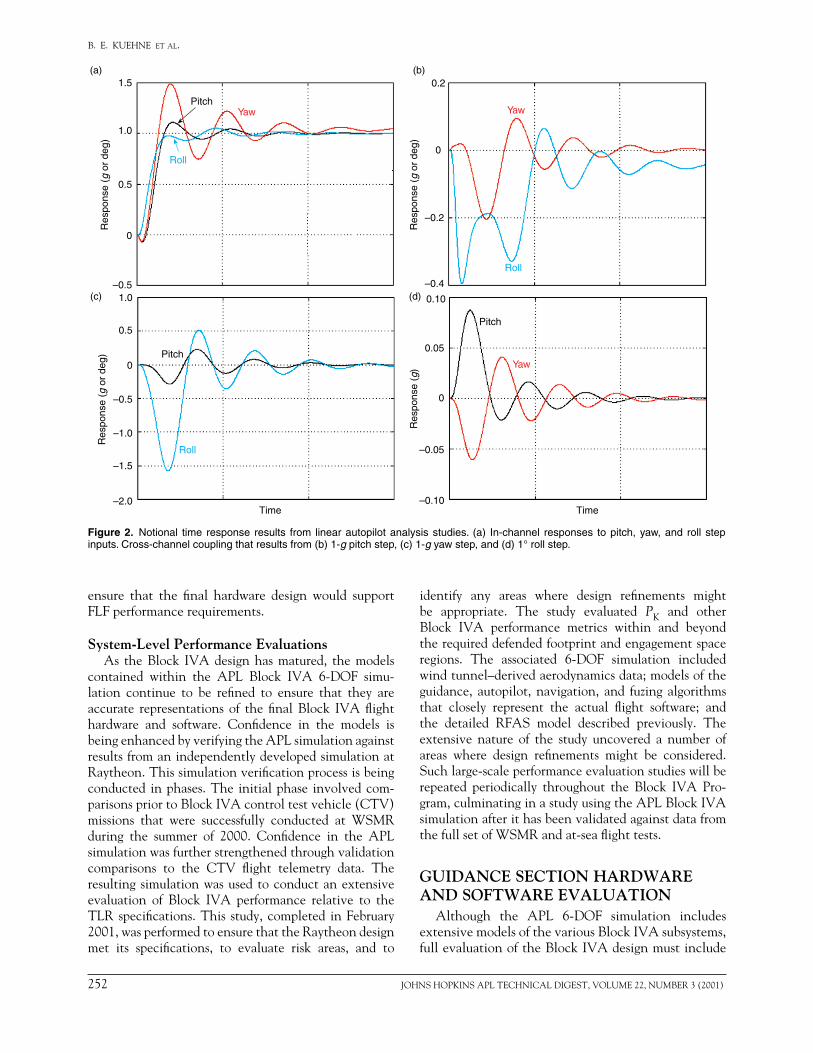
APLconductedtwogeneraltypesofautopilotevalu-ations toensure that theBlockIVAautopilotmet itsspecifiedperformanceobjectives.Linearcontrolsystemanalysis techniques were used to obtain a measureof missile response time at flight conditions spanningthe design space (Fig. 2). Gain and phase stabilitymargins were also computed via linear analysis tech-niques through characterization of the open-loop fre-quencyresponseoftheautopilotdesign.Theresultswere
summarized in termsof statisticaldistributionsofper-formance over the flight envelope. APL also exten-sively investigated missile autopilot performance byexercising the Block IVA 6-DOF simulation. In con-trast to the linear analysis results, the 6-DOF simula-tionyieldsnonlinearmeasuresofautopilotperformancethat include the effect of missile acceleration limit-ing,actuatorratelimits,andangleofattack–dependentvariations in airframe properties that are not readilycapturedthroughlinearanalyses.Duringthese6-DOFsimulationevaluations,missilelateralaccelerationandfinpositionandrate responseswereexamined foranyevidenceofcontrolsysteminstability.Achievedlateralaccelerationswerealsocomparedtotheautopilotcom-mands for complex maneuver command inputs. ThecombinationoflinearandnonlinearautopilotanalysesperformedbyAPLpointedtoareasof thedesignthatrequiredrefinement(confirmingRaytheonresults)andtherebyhelpedtoensurethattheBlockIVAautopilotdesignwouldmeetitsperformancerequirements.
Forward-Looking Fuze EvaluationsA critical new feature of the Block IVA design is
the FLF. To analyze the capabilities of the RaytheonFLFdesign,APLdevelopedadetailedmodelofboththeFLFalgorithmsandtheIRandRFASsensorsthatpro-videdataforthewarheadbursttimecalculations.TheRFAS modeling was particularly challenging becauseof the need to accurately represent the computation-allyintensivesignalprocessingthatispartoftheactualflightcodewhilestillmaintainingamodelthatiscon-sistentwith6-DOFsimulationthroughputconstraints.Tomodel this complexprocess in away that is com-putationally efficient enough to be used in the APL6-DOF simulation, elements of the RFAS responsearecomputed fromananalyticalclosed-formsolution.The approach used also requires a target radar crosssection(RCS)representationthatmodelsthedistinctradarscatterersassociatedwiththetargetvehicle.Suchmodels were developed by the Naval Air WarfareCenter,basedonprocessingoftesttargetvehicleRCSmeasurements using inverse synthetic aperture radartechniques.
Thehigh-fidelityRFASmodelincombinationwiththe target RCS models were used to investigate theabilityoftheRFAStoprovideaccuratetargetmeasure-ments.6-DOFsimulationrunsindicatethatthemea-surementaccuracybecomesincreasinglybetterastheRFAStransitionsthroughitsvariousprocessingmodes.Similar studieswereperformed toassessRFASaccu-racy for sensor characteristics representative of earlyproof-of-design hardware. These later studies, whichmodeledthecharacteristicsoftheactualearlydevel-opmental hardware, pointed to areas where designimprovementswerewarranted.Accordingly,Raytheonintroduced enhancements into the RFAS design to
Figure 1. Computed Block IVA intercept altitude dispersion as a function of SPY radar track settling time and downrange impact point. The data indicate that intercept altitude variations are reduced as track settling times increase.
0Downrange impact point
Alti
tude
sta
ndar
d de
viat
ion,
al
t
Increasingsettling time
252 JOHNSHOPKINSAPLTECHNICALDIGEST,VOLUME22,NUMBER3(2001)
B. E. KUEHNE et al.
ensure that the final hardware design would supportFLFperformancerequirements.
System-Level Performance EvaluationsAs theBlock IVAdesignhasmatured, themodels
contained within the APL Block IVA 6-DOF simu-lation continue to be refined to ensure that they areaccurate representations of the final Block IVA flighthardware and software. Confidence in the models isbeingenhancedbyverifyingtheAPLsimulationagainstresultsfromanindependentlydevelopedsimulationatRaytheon.Thissimulationverificationprocessisbeingconducted inphases.The initialphase involvedcom-parisonspriortoBlockIVAcontroltestvehicle(CTV)missions that were successfully conducted at WSMRduring the summer of 2000. Confidence in the APLsimulationwasfurtherstrengthenedthroughvalidationcomparisons to the CTV flight telemetry data. Theresultingsimulationwasusedtoconductanextensiveevaluation of Block IVA performance relative to theTLRspecifications.This study,completed inFebruary2001,wasperformedtoensurethattheRaytheondesignmet its specifications, to evaluate risk areas, and to
identify any areas where design refinements mightbe appropriate. The study evaluated PK and otherBlock IVA performance metrics within and beyondtherequireddefendedfootprintandengagementspaceregions. The associated 6-DOF simulation includedwindtunnel–derivedaerodynamicsdata;modelsoftheguidance, autopilot,navigation, and fuzing algorithmsthat closely represent the actual flight software; andthe detailed RFAS model described previously. Theextensive nature of the study uncovered a number ofareas where design refinements might be considered.Suchlarge-scaleperformanceevaluationstudieswillberepeated periodically throughout the Block IVA Pro-gram,culminatinginastudyusingtheAPLBlockIVAsimulationafterithasbeenvalidatedagainstdatafromthefullsetofWSMRandat-seaflighttests.
GUIDANCE SECTION HARDWARE AND SOFTWARE EVALUATION
Although the APL 6-DOF simulation includesextensivemodelsofthevariousBlockIVAsubsystems,fullevaluationoftheBlockIVAdesignmustinclude
Figure 2. Notional time response results from linear autopilot analysis studies. (a) In-channel responses to pitch, yaw, and roll step inputs. Cross-channel coupling that results from (b) 1-g pitch step, (c) 1-g yaw step, and (d) 1° roll step.
0.2
0
–0.2
–0.4
Res
pons
e (g
or
deg)
1.5
1.0
0.5
0
–0.5
Res
pons
e (g
or
deg)
1.0
0.5
0
–0.5
–1.0
–1.5
–2.0
Res
pons
e (g
or
deg)
0.10
0.05
0
–0.05
–0.10
Res
pons
e (g
)
PitchYaw
Roll
Yaw
Roll
Roll
PitchYaw
Pitch
(a) (b)
(c) (d)
Time Time

JOHNSHOPKINSAPLTECHNICALDIGEST,VOLUME22,NUMBER3(2001) 253
STANDARD MISSILE-2 BLOCK IVA ANALYSIS AND TEST
assessment of the hardware and software as actuallyimplemented into the missile. Since 1964, APL hasevaluatedSMguidancesectionhardwareandsoftwarein the GSEL. (General GSEL capabilities, includingfuture upgrades to the facility beyond those summa-rized in this article, aredescribedbyMarcotteetal.,this issue.) APL GSEL evaluations have historicallyassessed the hardware differently from the way it isdone at corresponding design agent facilities. Thedesignagenttypicallyevaluatesthedesignagainstitsdocumentedflowed-downrequirements.APL,ontheotherhand,alsoevaluatestheperformanceoftheinte-grated hardware and software design in a variety of“what-if ” situations.Forexample,duringGSELtest-ing performed prior to the Block IVA RRFD guidedflighttest,APLdeterminedthatanunexpectedtran-sient in the estimated time-to-go information couldcausetheIRseekertoattempttargetacquisitionbeforetheIRdomecoverwasejected.Thisproblemwassub-sequentlycorrectedintheflightsoftwarepriortothesuccessful flight test. Hence, GSEL testing comple-mentstestsbeingperformedatdesignagentfacilities.
For the Block IVA Program, GSEL testing of theBlock IVAguidance section is providing an indepen-dentevaluationoftheBlockIVARFsemi-activeseeker,RFAS,IRsensor,andassociatedsignalprocessingfunc-tions.Thesetestsaddressverificationoftheoverallinte-grated system, including proper operation and timinginbothclearandcountermeasuresenvironments.Withthe addition of the new IR seeker and RFAS intotheBlockIVAconfiguration,theevaluationsarefocus-ingonassessmentofIRacquisition,targetdesignationand handover logic, IR track and guidance, and FLF.DuringinitialBlockIVAProgramtesting,theIRseekerhasbeenremovedfromtheremainderoftheguidancesectionandmountedonaseparateopticalbenchlocatedin conjunction with an IR source. This configurationallowstheIRseekertobetestedeitherindependentlyorwhileelectricallyconnectedtotheremainderoftheguidance section (across a digital interface) for com-binedRF/IRtesting.Inthelattercase,themotionsoftheRFandIRsources(i.e.,targetmotions)aresynchro-nizedsothatthesystemsimulatestheRFandIRinputthatwouldbeseenfromasingletargetandpresentedtoanintegratedguidancesection.
The FLF function and associated RFAS sensor areuniquetotheBlockIVAdesign,resultingintheneedtodevelopanewRFAStargetgeneratorforGSELBlockIVAtesting.TheRFAStargetgeneratorsimulatesthetargetreturnreceivedbytheRFASduringaninterceptengagement.Thetargetgeneratorsendsasequenceofelectrical inputs to the guidance section under test;thosesignalsarebasedonaprecomputedtableofend-gameparametersfromtheAPLBlockIVA6-DOFsim-ulation.Theparameterssentarefunctionsofthetargetlengthandaspect.TheGSELhost computer initiates
“playback”ofthescriptsattheappropriatetimeduringthetestrun.InterfacelogicdetectstheRFAScarrierfre-quencyandthetimeofradartransmissionfromtheguid-ancesection.Whenthetransmitsignalisdetected,ded-icatedinterfacelogicusesthetableoutputtodeterminein real time the appropriate instantaneous RF targetreturnsignalcharacteristics.Themissilefrequencyref-erenceisprovidedtotheRFAStargetgeneratorsystemtoensureacommonreference,thusachievinganaccu-ratesimulationoftheradarreturn.
GSEL testing for the Block IVA Program alsoincludesevaluationofthenewIRseeker.TwoIRscenesimulators are available to optically project calibratedIR scenes to the seeker under test. Stand-alone IRtestscanuseeitherof these simulators,whichare theInfraredEnvironmentSimulator(IRES)(usedinprevi-ousRRFDtesting)andthenewThermalPictureSyn-thesizer(TPS).TheIREScansimulateanexpanding,movingtargetimposedonabackgroundthatrepresentsthe heated IR dome. Target size can be dynamicallyvariedfromanunresolvedimagetoonethatcoversthemaximum extent of an approaching target in the IRseeker field of view. The target aperture is back-illuminated with a calibrated blackbody source thatranges from 50° to 1000°C. The background is illu-minatedwithanextendedareablackbody source thatranges from ambient to 600°C. A pair of matched,variable-attenuating wheels is used to allow thebackground tobe rapidly rampedup in radiance.Thewheels are counter-rotated to maintain a spatiallyuniform background that dynamically changes thebackgroundtemperaturetosimulatetheheatingoftheseekerdomeduringflight.
TheTPS(Fig.3)isa256256calibratedthermalresistorarraywithanapparentpixeltemperaturerange
Figure 3. The IR seeker scene simulators, which consist of the TPS and IRES. The resistor array of the TPS is behind the circular window in the center of the blue box.
254 JOHNSHOPKINSAPLTECHNICALDIGEST,VOLUME22,NUMBER3(2001)
B. E. KUEHNE et al.
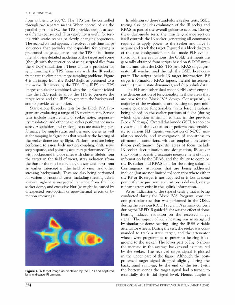
from ambient to 200°C. The TPS can be controlledthroughtwoseparatemeans.WhencontrolledviatheparallelportofaPC,theTPSprovidesoutputatsev-eralframespersecond.Thiscapabilityisusefulfortest-ing with static scenes or slowly changing sequences.Thesecondcontrolapproachinvolvesareal-timeimagesequencer that provides the capability for playing apredefined image sequence into theTPSat full framerate,allowingdetailedmodelingofthetargetandscene(thoughwiththerestrictionofusingscriptedfilesfromthe 6-DOF simulation). There is also a provision forsynchronizing the TPS frame rate with the IR seekerframeratetoeliminateimagesamplingproblems.Figure4 is an image from theRRFDflight aspresented to amid-wave IRcameraby theTPS.TheIRESandTPSimagescanalsobecombined,withtheTPSscenefoldedinto the IRESpath to allow theTPS to generate thetargetsceneandtheIREStogeneratethebackgroundandtoprovidescenemotion.
Stand-aloneIRseekertestsfortheBlockIVAPro-gramareevaluatingarangeofIRrequirements.Sensortests include measurement of seeker noise, responsiv-ity,resolution,andotherbasicseekerperformancemea-sures.Acquisitionandtracking testsareassessingper-formance for simplestaticanddynamicscenesaswellasforrampingbackgroundsthatsimulatetheheatingoftheseekerdomeduringflight.Platformtestsarebeingperformedtoassessbodymotioncoupling,drift, servostepresponse,andpointingaccuracyperformance.Testswithbackgroundincludecaseswithclutter(debrisfromthe target in the field of view), stray radiation (fromtheSunorthemissileforebody),awarheadburstfroman earlier intercept in the field of view, and otherstressing backgrounds. Tests are also being performedforvariousoff-nominalcases,includingstressingdebrisscenes, higher-than-expected radiance from the hotseekerdome,andexcessiveblur(asmightbecausedbyunexpected aero-optical or aero-thermal effects or bymotionsmearing).
Inadditiontothesestand-aloneseekertests,GSELtestingalso includes evaluationof the IR seeker andRFASaspartoftheoverallguidancesection.Duringthese dual-mode tests, the missile guidance sectionitselfcontrolstheIRseeker,generatingallcommandsrequired to apply power to the seeker and have itacquireandtrackthetarget.Figure5isablockdiagramof the test configuration for dual-mode FLF evalua-tions.Fortheseevaluations,theGSELtestinputsaregenerallyobtainedfromscriptsbasedon6-DOFsimu-lationruns,withtheIRES,TPS,andRFAStargetgen-eratorall synchronized through theGSELhostcom-puter. The scripts include IR target information, RFtarget information, RFAS inputs, inertial instrumentoutput(missilestatedynamics),andshipuplinkdata.
TheFLFandotherdual-modeGSELtestsempha-sizedemonstrationoffunctionalityinthoseareasthatare new for the Block IVA design. Consequently, amajorityoftheevaluationsarefocusingonpost-mid-course guidance functionality, with lesser emphasisbeingplacedontheearlierportionsofflight(duringwhich operation is similar to that in the previousBlockIVdesign).Overalldual-modeGSELtestobjec-tivesincludetheevaluationofperformancesensitiv-itytovariousFLFinputs,verificationof6-DOFsim-ulation models, and investigation of robustness tooff-nominal conditions, with an emphasis on sensorfusion performance. Specific areas of focus includeIR seeker discrimination and designation, IR seekertrackpointprocessing,accuratemeasurementoftargetinformationbytheRFAS,andtheabilitytocombinetheIRseekerandRFASdataforthefuzingsolution.Contingency situations that are being addressedinclude(butarenotlimitedto)scenarioswhereeithertheRForIRtargetisnotacquiredorislostatsomepointafteracquisition,acquisition isdelayed,or sig-nificanterrorsexistintheuplinkinformation.
Asanindicationofthetypeoftestingthatisbeingconducted during the Block IVA Program, considerone particular test that was performed in the GSELduringthepreviousRRFDProgram.AprimaryconcernduringtheRRFDIRguidedflightwastheeffectofdomeheating–induced radiation on the received targetsignal. The impact of such heating was investigatedby simulating dome heating using the IRES variableattenuatorwheels.Duringthetest,theseekerwascom-manded to track a static target, and the attenuatorwheels were programmed to present a heating back-groundto the seeker.The lowerpartofFig.6 showsthe increase in the average background as measuredby the seeker. The received target signal is plottedin the upper part of the figure. Although the post-processed target signal dropped slightly during thebackground ramp-up, by the end of the test (withthe hottest scene) the target signal had returned toessentially the initial signal level. Hence, despite a
Figure 4. A target image as displayed by the TPS and captured by a mid-wave IR camera.

JOHNSHOPKINSAPLTECHNICALDIGEST,VOLUME22,NUMBER3(2001) 255
STANDARD MISSILE-2 BLOCK IVA ANALYSIS AND TEST
100-fold increase in the background radiation, theaveragetargetsignalshowedlittlevariation.
IR DOME TESTINGWhileGSELtesting(supplementedby6-DOFsimu-
lationanalysis)evaluatesthefunctionalityoftheinte-gratedhardware and softwaredesigns relative to their
requirements, it is not able to address survival of thesapphireIRdomeinthepresenceofthethermalstressescreatedinthehigh-velocityBlockIVAflightenviron-ment. This area has been addressed via aerothermaland structural analyses, which were in turn validatedthroughwindtunneltesting.
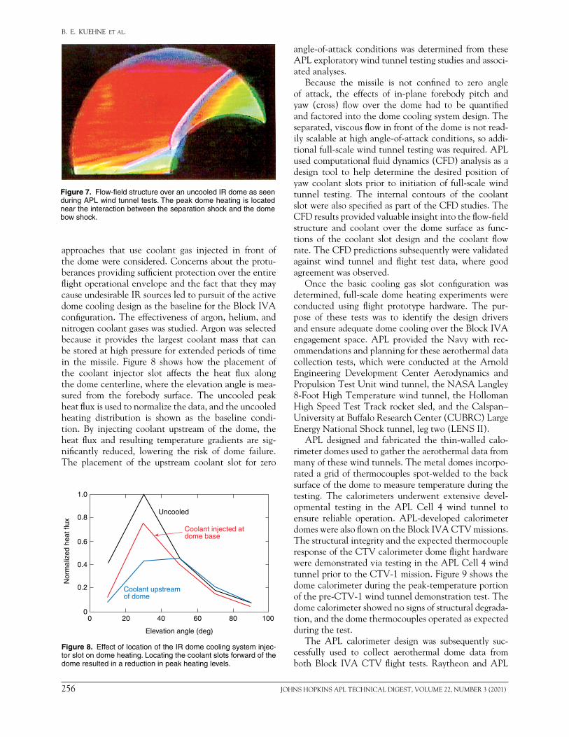
Prior to the actual start of theBlock IVAProgram,APL played a major role in developing the enablingtechnologies for the IR seeker dome. The dome, side-mounted about 1 m downstream from the nose, inter-actswiththeairflowtogeneratecomplexshockandflow-field patterns that are unique functions of the missilespeed,angleofattack,altitude,andexternaldomecool-inggasmassflowrate.Figure7showstheuncooleddomeflowfieldasvisualizedduringtestsconductedintheAPLAveryAdvancedTechnologyDevelopmentLaboratoryCell4wind tunnel.The full-scaledomewas testedonashortenedforebodytoproducetherepresentativeflowinteractionsthatmostgreatly influencethedomether-mostructuralresponse.Highaerothermalheatingoccursnear the intersection of the boundary layer separationshockandthedomebowshock.Withoutathermalpro-tection system, these heating patterns could generateasymmetrictemperaturedistributionsthatelevatemate-rialstressesbeyondthesapphirestrengthlimits,causingabrittlefractureofthedome.
Initial exploratory testing in the APL Cell 4 windtunnelexaminedninedomeheatfluxreductiontech-niques. Passive techniques that use upstream protu-berances to lower the surface heating gradients and
Figure 5. Diagram of the APL dual-mode GSEL test configuration, showing the coordinated control of both the IR seeker scene simula-tors (the IRES and TPS scene projector) and the RFAS target generator. (IMU = inertial measurement unit, LOS = line of sight, SCS = steering control section, TDD = target detection device.)
Figure 6. IR target tracking results with a ramping hot-dome background. The lower part of the figure shows the increase in the average background versus time. The upper part shows that the peak target signal varies only slightly despite the significant increase in background level.
0
5
10
15
20
Targ
et s
igna
l (co
unts
)
102
101
100Ave
rage
of b
ackg
roun
d(c
ount
s)
Time
RF guidancesection
FLFsoftware
Sceneprojector
Sceneprojectorcontroller
Image
IRES
IREScontroller
IR seeker
IR seekertest station
RFAStarget
generator
GSELhost computer
TDD, SCS,uplink/downlinkand initialization
simulators
IMUsimulator
6-DOFdata files
LOS
Semi-active RF
Controllines
Data acquisition(AP Labs andData Probe) Missile
state
Start scriptflag
Framesync
IR laboratory equipmentGuidance section under testRF laboratory equipment
Scripted IRtarget control data: Relative geometry Radiance data
Targetreturn
Scripted RFAScontrol data: Relative geometry Return power
256 JOHNSHOPKINSAPLTECHNICALDIGEST,VOLUME22,NUMBER3(2001)
B. E. KUEHNE et al.
approaches that use coolant gas injected in front ofthedomewereconsidered.Concernsabouttheprotu-berancesprovidingsufficientprotectionovertheentireflightoperationalenvelopeandthefactthattheymaycauseundesirableIRsourcesledtopursuitoftheactivedomecoolingdesignasthebaselinefortheBlockIVAconfiguration.Theeffectivenessofargon,helium,andnitrogencoolantgaseswasstudied.Argonwasselectedbecause it provides the largest coolant mass that canbestoredathighpressureforextendedperiodsoftimein the missile. Figure 8 shows how the placement ofthe coolant injector slot affects the heat flux alongthedomecenterline,wheretheelevationangleismea-sured from the forebody surface. The uncooled peakheatfluxisusedtonormalizethedata,andtheuncooledheating distribution is shown as the baseline condi-tion. By injecting coolant upstream of the dome, theheat flux and resulting temperature gradients are sig-nificantly reduced, lowering the risk of dome failure.The placement of the upstream coolant slot for zero
angle-of-attack conditions was determined from theseAPLexploratorywindtunneltestingstudiesandassoci-atedanalyses.
Because the missile is not confined to zero angleof attack, the effects of in-plane forebody pitch andyaw (cross) flow over the dome had to be quantifiedandfactoredintothedomecoolingsystemdesign.Theseparated,viscousflowinfrontofthedomeisnotread-ilyscalableathighangle-of-attackconditions,soaddi-tionalfull-scalewindtunneltestingwasrequired.APLusedcomputationalfluiddynamics(CFD)analysisasadesign tool to help determine the desired position ofyawcoolant slots prior to initiationof full-scalewindtunnel testing. The internal contours of the coolantslotwerealsospecifiedaspartoftheCFDstudies.TheCFDresultsprovidedvaluableinsightintotheflow-fieldstructure and coolant over the dome surface as func-tions of the coolant slot design and the coolant flowrate.TheCFDpredictionssubsequentlywerevalidatedagainst wind tunnel and flight test data, where goodagreementwasobserved.
Once the basic cooling gas slot configuration wasdetermined, full-scaledomeheatingexperimentswereconducted using flight prototype hardware. The pur-pose of these tests was to identify the design driversandensureadequatedomecoolingovertheBlockIVAengagement space. APL provided the Navy with rec-ommendationsandplanningfortheseaerothermaldatacollection tests, which were conducted at the ArnoldEngineering Development Center Aerodynamics andPropulsionTestUnitwindtunnel,theNASALangley8-FootHighTemperaturewindtunnel, theHollomanHighSpeedTestTrackrocketsled,andtheCalspan–UniversityatBuffaloResearchCenter(CUBRC)LargeEnergyNationalShocktunnel,legtwo(LENSII).
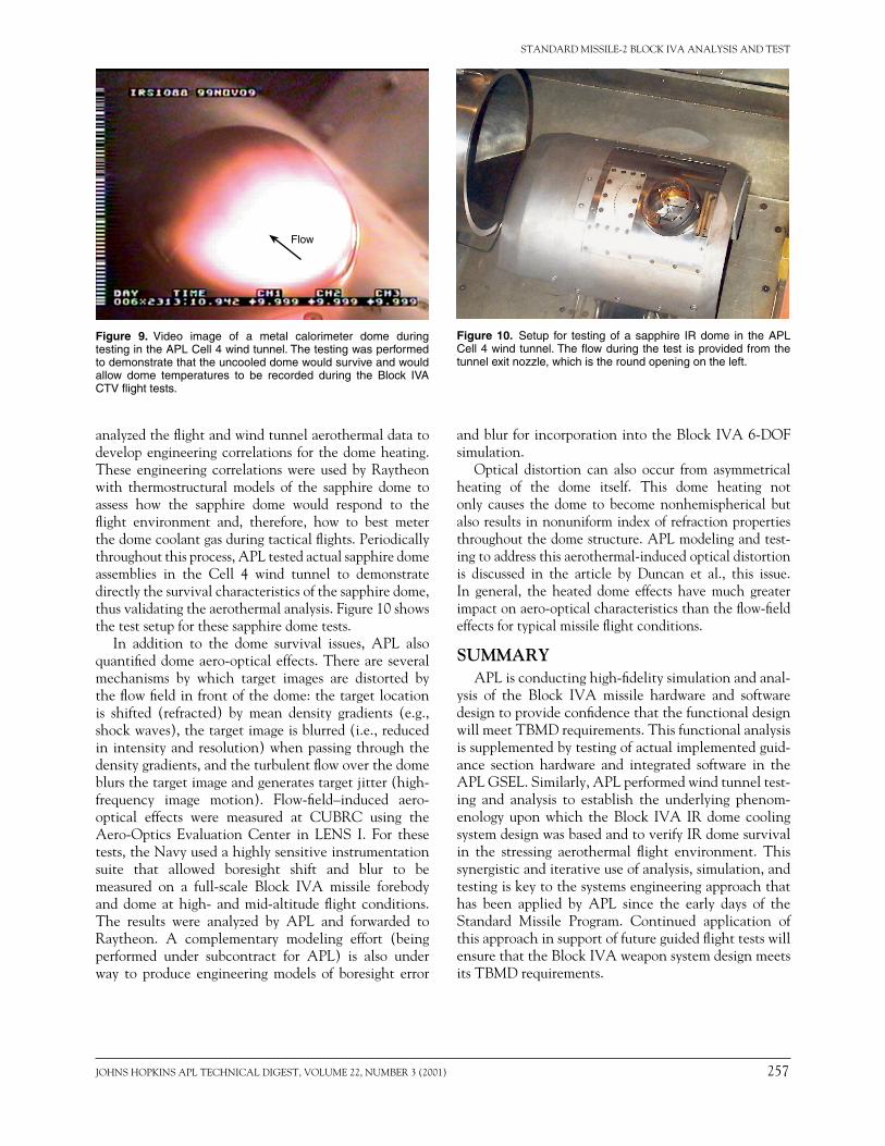
APL designed and fabricated the thin-walled calo-rimeterdomesusedtogathertheaerothermaldatafrommanyofthesewindtunnels.Themetaldomesincorpo-ratedagridofthermocouplesspot-weldedtothebacksurfaceofthedometomeasuretemperatureduringthetesting. The calorimeters underwent extensive devel-opmental testing in the APL Cell 4 wind tunnel toensure reliable operation. APL-developed calorimeterdomeswerealsoflownontheBlockIVACTVmissions.ThestructuralintegrityandtheexpectedthermocoupleresponseoftheCTVcalorimeterdomeflighthardwareweredemonstratedviatestingintheAPLCell4windtunnelpriortotheCTV-1mission.Figure9showsthedomecalorimeterduringthepeak-temperatureportionofthepre-CTV-1windtunneldemonstrationtest.Thedomecalorimetershowednosignsofstructuraldegrada-tion,andthedomethermocouplesoperatedasexpectedduringthetest.
The APL calorimeter design was subsequently suc-cessfully used to collect aerothermal dome data fromboth Block IVA CTV flight tests. Raytheon and APL
Figure 7. Flow-field structure over an uncooled IR dome as seen during APL wind tunnel tests. The peak dome heating is located near the interaction between the separation shock and the dome bow shock.
Figure 8. Effect of location of the IR dome cooling system injec-tor slot on dome heating. Locating the coolant slots forward of the dome resulted in a reduction in peak heating levels.
Uncooled
Coolant injected atdome base
Coolant upstreamof dome
1.0
0.8
0.6
0.4
0.2
00 20 40 60 80 100
Elevation angle (deg)
Nor
mal
ized
hea
t flu
x
JOHNSHOPKINSAPLTECHNICALDIGEST,VOLUME22,NUMBER3(2001) 257
STANDARD MISSILE-2 BLOCK IVA ANALYSIS AND TEST
analyzedtheflightandwindtunnelaerothermaldatatodevelopengineeringcorrelations for thedomeheating.These engineering correlations were used by Raytheonwith thermostructural models of the sapphire dome toassess how the sapphire dome would respond to theflight environment and, therefore, how to best meterthedomecoolantgasduringtacticalflights.Periodicallythroughoutthisprocess,APLtestedactualsapphiredomeassemblies in the Cell 4 wind tunnel to demonstratedirectlythesurvivalcharacteristicsofthesapphiredome,thusvalidatingtheaerothermalanalysis.Figure10showsthetestsetupforthesesapphiredometests.
In addition to the dome survival issues, APL alsoquantifieddomeaero-opticaleffects.Thereareseveralmechanisms by which target images are distorted bytheflowfieldinfrontofthedome:thetargetlocationis shifted (refracted) by mean density gradients (e.g.,shockwaves),thetargetimageisblurred(i.e.,reducedinintensityandresolution)whenpassingthroughthedensitygradients,andtheturbulentflowoverthedomeblursthetargetimageandgeneratestargetjitter(high-frequency image motion). Flow-field–induced aero-optical effects were measured at CUBRC using theAero-Optics Evaluation Center in LENS I. For thesetests,theNavyusedahighlysensitiveinstrumentationsuite that allowed boresight shift and blur to bemeasured on a full-scale Block IVA missile forebodyanddomeathigh- andmid-altitudeflight conditions.The results were analyzed by APL and forwarded toRaytheon. A complementary modeling effort (beingperformed under subcontract for APL) is also underway to produce engineering models of boresight error
andblurforincorporationintotheBlockIVA6-DOFsimulation.
Optical distortion can also occur from asymmetricalheating of the dome itself. This dome heating notonly causes the dome to become nonhemispherical butalsoresultsinnonuniformindexofrefractionpropertiesthroughoutthedomestructure.APLmodelingandtest-ingtoaddressthisaerothermal-inducedopticaldistortionis discussed in the article by Duncan et al., this issue.In general, the heated dome effects have much greaterimpactonaero-opticalcharacteristicsthantheflow-fieldeffectsfortypicalmissileflightconditions.
SUMMARYAPLisconductinghigh-fidelitysimulationandanal-
ysis of the Block IVA missile hardware and softwaredesigntoprovideconfidencethatthefunctionaldesignwillmeetTBMDrequirements.Thisfunctionalanalysisissupplementedbytestingofactualimplementedguid-ance section hardware and integrated software in theAPLGSEL.Similarly,APLperformedwindtunneltest-ing and analysis to establish the underlying phenom-enologyuponwhich theBlock IVAIRdomecoolingsystemdesignwasbasedandtoverifyIRdomesurvivalin the stressing aerothermal flight environment. Thissynergisticanditerativeuseofanalysis,simulation,andtestingiskeytothesystemsengineeringapproachthathas been applied by APL since the early days of theStandard Missile Program. Continued application ofthisapproachinsupportoffutureguidedflighttestswillensurethattheBlockIVAweaponsystemdesignmeetsitsTBMDrequirements.
Figure 9. Video image of a metal calorimeter dome during testing in the APL Cell 4 wind tunnel. The testing was performed to demonstrate that the uncooled dome would survive and would allow dome temperatures to be recorded during the Block IVA CTV flight tests.
Flow
Figure 10. Setup for testing of a sapphire IR dome in the APL Cell 4 wind tunnel. The flow during the test is provided from the tunnel exit nozzle, which is the round opening on the left.
258 JOHNSHOPKINSAPLTECHNICALDIGEST,VOLUME22,NUMBER3(2001)
B. E. KUEHNE et al.
THE AUTHORS
BRUCEE.KUEHNEisamemberofAPL’sPrincipalProfessionalStaffandProgramManagerfortheSM-2BlockIVAProgram.HejoinedtheLaboratoryin1975aftergraduatingfromPurdueUniversitywithB.S.andM.S.degreesinengineeringsci-ence,specializingincontroltheory.Mr.Kuehnehasextensiveexperienceinmod-elingandanalysisofmissileguidancesystemsandhasparticipatedinthedevelop-ment,verification,andmanagementofhigh-fidelity simulations forboththeSMandTomahawkprograms.PriortobecomingProgramManagerfortheBlockIVAmissilein1997,Mr.KuehneservedastheLeadEngineerfortheBlockIVARiskReductionFlightDemonstrationProgram.HeisamemberoftheAIAA.Hise-mailaddressisbruce.kuehne@jhuapl.edu.
ROBERT A. PATTERSON received a B.S. in electrical engineering from theGeorgiaInstituteofTechnologyin1989andanM.S.inelectricalengineeringfromTheJohnsHopkinsUniversityin1992.Mr.PattersonjoinedAPLin1989andistheChiefEngineerfortheSM-2BlockIVAProgramaswellastheSupervisoroftheSystemSimulationSectioninADSD’sMissileSystemsGroup.HeisCoordinatorfortheSM-2BlockIVAsix-degree-of-freedomandend-to-endAegisSM-2BlockIVAsimulations,theLeadatAPLforTBMDflighttestscenariodevelopment,andtheLead for simulation,verification,validation, andaccreditationefforts for theBlock IVAProgram.Hehaspresentedpapers onweapon systemperformance atrecentNationalFireControlSymposiaandotherTBMDconferences.Mr.Patter-son’[email protected].
JOHNE.SCHMIEDESKAMPreceivedaB.S.inphysicsfromtheUniversityofIllinoisin1986andanM.S.inelectricalengineeringfromTheJohnsHopkinsUniversityin1990.HejoinedtheAnti-AirWarfareSystemsEngineeringGroupin1987andhasworkedonNATOSeasparrow,RollingAirframeMissile,andBattleGroupAAWCooperationefforts.In1993hetransferredtotheMissileSystems Analysis Group where he has worked on SM Block IVA projects,performinganalyses forboth the initialRiskReductionFlightDemonstrationeffortandtheEngineeringandManufacturingDevelopmentProgram.Heiscur-rentlysupportingtheBlockIVAForwardLookingFuzeevaluations,includinganalysisof fuzingcritical experiments.Mr.Schmiedeskamp’s e-mail address [email protected].
JOHNSHOPKINSAPLTECHNICALDIGEST,VOLUME22,NUMBER3(2001) 259
STANDARD MISSILE-2 BLOCK IVA ANALYSIS AND TEST
GREGG A. HARRISON is a member of APL’s Senior Professional Staff and amemberoftheGuidanceandControlteamfortheSM-2BlockIVAProgram.HeholdsB.SandM.S.degreesinmathematicsfromtheUniversityofCalifornia,Riv-erside,anM.S.E.E.inaerospacecontrolsfromU.S.C.,andiscurrentlypursuinganM.S.E.E.incontrolsandsignalprocessingfromtheJHUWhitingSchoolofEngi-neering.HecametoAPLin1993afterworkingintheaerospaceindustryforsev-eralyears,primarilyonspacecraftprograms.Mr.Harrisonhasextensiveexperiencein modeling, analysis, and simulation of aerospace systems, primarily spacecraftattitudecontrolandmissileguidanceandcontrolsystems.Heisaseniormemberof theAmericanInstituteofAeronauticsandAstronautics.Hise-mailaddress [email protected].
MATTHEWE.ANTONICELLIisamemberofAPL’sPrincipalProfessionalStaffand a Section Supervisor in the Radio Frequency Missile Systems Group in thePowerProjectionSystemsDepartments.HereceivedaB.S.inelectricalengineeringfromThePennsylvaniaStateUniversityin1980andanM.S.inelectricalengineer-ing from The Johns Hopkins University in 1986. Since joining APL in 1981,his activities have focused on hardware-in-the-loop validation and performancecharacterization of software and hardware for tactical missile guidance systems.He is responsible for the development of extensive upgrades to GSEL for thetesting and evaluation of SM Block IV and SM Block IVA variants. He is amemberoftheInstituteofElectricalandElectronicsEngineers.Hise-mailaddressismatt.antonicelli@jhuapl.edu.
LINDAM.HOWSERisamemberofAPL’sSeniorProfessionalStaffintheElec-tro-OpticalSystemsGroupoftheAirDefenseSystemsDepartment.ShereceivedaB.S.inengineeringsciencefromLoyolaCollegein1981andanM.S.inelectri-calengineeringfromTheJohnsHopkinsUniversityin1985.SincejoiningAPLin1981,Ms.Howserhasworkedonimageprocessing,simulation,andtestingofavis-ibleguidancesystemandreal-timeprogramming.Morerecently,shehasbeenmod-elingandtestinginfraredseekers.Here-mailaddressislinda.howser@jhuapl.edu.
STEVENA.LUTZ is amemberofAPL’sPrincipalProfessionalStaff and is theLeadEngineer for the IRdomeanalyses and testingatAPL for theSM-2BlockIVAProgram.Hecame to theLaboratory in1985 fromtheU.S.DepartmentofEnergy, where he analyzed and designed optical access ports for laser diagnosticinstrumentationofcoalconversionsystems.HegraduatedfromWestVirginiaUni-versitywithB.S.,M.S.,andPh.D.degreesinmechanicalengineering,specializinginfluiddynamicsandheat transfer.Dr.Lutzhasextensiveaerothermalandfluiddynamictestingexperienceinsubsonic,supersonic,andhypersonicwindtunnels,shocktunnels,arcjets,androcketsleds.Hehasdevelopedengineeringmodelsforanalyzing turbulentboundary layers andcomplex shockwave interactions.He isaseniormemberoftheAmericanInstituteofAeronauticsandAstronautics.Hise-mailaddressissteve.lutz@jhuapl.edu.