. Standard Interfaces Control Docu ment - NASA · ,f"" ICD 2-1 M001 . Orbiter Middeck/Payload \....
90
,f"" ICD 2-1 M001 . Orbiter Middeck/Payload \. Standard Interfaces Control Docu ment NASA-TM-8747319850018529 National Space Transportation Systems Program Office March 1984 NI\S/\ National Aeronautics and Space Administration . Lyndon B. Johnson Space Center Houston, Texas ,', , . , .'. '1{")0[, 1 :,:': ' 1:',0 r U.NGLEY RES[,'\RC',d CENTER . i"l." ... Sf\ Vlf(GINIA 111111111111111111111111111111111111111111111 NF01546 ------------------- https://ntrs.nasa.gov/search.jsp?R=19850018529 2020-02-22T01:53:01+00:00Z
Transcript of . Standard Interfaces Control Docu ment - NASA · ,f"" ICD 2-1 M001 . Orbiter Middeck/Payload \....
,f""
ICD 2-1 M001
. Orbiter Middeck/Payload \. Standard Interfaces Control Docu ment NASA-TM-8747319850018529
National Space Transportation Systems Program Office
March 1984
NI\S/\ National Aeronautics and Space Administration .
Lyndon B. Johnson Space Center Houston, Texas
,',
, . , .'. '1{")0[, 1 :,:': ' 1:',0 r
U.NGLEY RES[,'\RC',d CENTER L;~)?r . .r~·1 i"l." ... Sf\
H.;::?TC~'I, Vlf(GINIA
111111111111111111111111111111111111111111111 NF01546
-------------------,,~-----r
https://ntrs.nasa.gov/search.jsp?R=19850018529 2020-02-22T01:53:01+00:00Z

ENTER:D 85N26840 DISPLAY 85N268~0/2
85N25840*# ISSUE 16 PAGE 2729 CATEGORY 16 RPT#: NASA-TM-87473 ICD-2-1-M001 NAS 1.15:87473 84/03/00 r8 ~~GES UNCLASSIFIED DOCUMENT
UTTL: Orbiter middeck/payload standard interfaces control document CORP: N~tional Aeronautics:~'lci tpace Administration. Lyndon B. Johnson Space
Center, Houston. Tex. AVAIL. NTIS SAP: HC ADS/MF ADl MAJS: I*CONSTRAINTS/*INTERFACES/*SPACE SHUTTLE PAYLOADS/*SPECIFICATIONS HINS: 1 AVIONICSI DOCUMENTATIONI ELECTRIC CONNECTORS 1 POLICIESI STRUCTURAL
DESIGN CRITERIAI SYSTEMS COMPATIBILITY ABA: Author ABS: The interfaces which shall be provided by the baseline shuttle mid-decK
for payload use within the mid-deck area are defined. as well as all constraints which shall be observed by ~ll the users of the defined interfaces. Commonality was established with respect to analytical approaches, analytical models. technical data and definitions for integrated analyses by all the interfacing parties. Any payload interfaces that are out of scope with the st~ndard interfaces defined shall be defined in a Payload Unique Interface Control Document (ICD) for a given payload. Each Payload Unique ICD will have comp~rable p~ragraphs to this ICD and will have a corresponding notation of A. for applicable; N/A, for not applicable; N, for note added for explanation; and E, for exception. On any flight. the STS reserves the right to assign locations to both paylo~ds mounted on an adapter plate(s) and payloads stored within
HORE ENTER:P DISPLAY 85N2684D/2
standard lockers. Specific locations requests and/or requirements exceeding standard mid-deck p~ylo~d reqUirements may result in a reduction in manifesting opportunities.

ORBITE2 MID-DECK/PAYLOAD
STANrARD INTERFACES
BASELINE APPROVED FEBRUARY 7. 1984
nOTICE - WHEN GOVENMENT DRAWINGS, SPE:IFICATIONS, OR OTHER DATA ARE USED FOR ANY PURPOSE OTHER THAN IN CONNECTION WITH A DEFINITELY RELATED GOVERNMENT PROCUREMENr OPERATION, THE UNITED STATES GOVERNMENT THEREBY INCURS NO RESPONSIBILITY NOR ANY OBLIGATION WHATSOEVER; AND THE FACT THAT THE GO VERUMEU'l' riA Y HA VE FORMULATED, FURNI5 BED, OR IN ANY WAY SIJPPLIED THE S AI D DRAW INGS, SPECIFICAr IONS, OR OT HER DATA MANNEF. LICENSING THE HOLDER OR ANY OTHER PERSON OR CORPORATION, OR CONVEYING ANY RIGHTS OR PERMISSION TO MANUFACTURE, USE, OR SELL ANY PATENTED INVENTION THAT MAY IN ANY WAY EE RELATED THERETO.
ii
T HIS PAGE INTENTIONALLY LEE'T BLA NK
iii
· -

"Pdragraph _I£!:!'!!!Q~.£_
1.0
1.1
1.2
1.3
1.5
1.5.1
1.5.2
1.5.3
2.0
2. 1
2.2
2.3
2.4
2.5
3.0
3 • 1
3.1.1
3.1.1.1
3.2
3.2.1
TABLE OF CONTENTS
SCOPE
PURPOSE
STANDAR!; MIDDECK PAYLOAD
ORGANIZATION OF DOCU:iENT
EFFECT IV ITY
CHANGE POLICY
DOCUM ENTS
APPLICABLE DOCUMENTS
REFERENCE DOCUMENTS
ROCKii ELL INT ERNAT IONAL ORA WINGS AND SPECIFICATIONS
INTERNATIONAL LATEX CORPORATION (ILe) DRAWINGS
ELECTRICAL CONNECTOR PART NUMBERS
PHYSICAL INTERFACES
GEOMETRlC RELATIONSHIPS
Orbiter Crew Module (C11)
INTERFACE LOCATION AND DIMENSIONING
iv
1- 1
1-1
1-1
1-1
1-2
1-2
1-2
1-2
1-2
2-1
2-1
2-2
2-2
2-2
2-2
3-1
3-1
3-1
3-1
3-1
3-1

Pacagr aph _li!!B&~L_
3.2.2
3.3
3.3.1
3.3.2
3.4
3.4.1
3.4.2
3.5
3.5.1
3.5.2
3.5.3
3.5.4
3.5.5
3.5.6
3.5.7
3.6
3.7
3.8
3.8.1
3.9
3.10
3.10.1
3.10.1.1
TABLE Of CONTENTS
STRUCTURAL INTERFACES
STANDARD PAYLOAD PROVISIONS
OPTIONAL PAYLOAD PROVISIONS
ATTACHMENT HARDWARE
PAYLOAD/GSE HARD POINTS
FIRE PROT fCTION
PAYLOAD ENVELOPE PROTRUSIONS
PAYLOAD-TO-ORBITER ELECTRICAL BOND
Povec Connector Bond
v
3-1
3-1
3-2
3-2
3-2
3-2
3-3
3-3
3-3
3-3
3-lJ
3-4
3-4
3-4
3-4
3-5
3-5
3-5
3-5
3-5
3-5
3-5
3-5

Pucagr-aph .JL~1!!hg£ __
3.10.1.2
J. 11
3.11.1
3.11.2
3.12
l~ .0
4. 1
4.2
4.4
4.5
" ' .... 0
4.6.1
4.6.1.1
4.6.1.2
4.6.1.3
4.6.1.4
4.7
4.8
5.0
5.1
TABLE OF CONTENTS
PdY loaj to STS Suppli ed Moun ting Surf ace Bond
POWER PROVISIONS
NOMENCL ATURE
STFUCTURAL INTERFACES
OPERATIONAL INERTIA LOADS
EM ERGEN CY L AN DING LOAD FACTORS
RANDOM VIBRATION
ACOUSTICS
KICK/PUSH-OFF LOADS
CENTER-Of-GRAVITY ALLOWANCE VERSUS WEIGHT
Standard Locker
Payloads Attached to a Single Plate
Payload Attached to a Double Plate
Payload Attached to a Payload Mounting Pan el (s)
FACTORS OF SAFETY FOR STRUCTURAL DESIGN
FRACTURE CONTROL
THERMAL INTERFACE
ENVIRON~ENTAL CONDITIONS
vi
3-6
3-6
3-6
3-6
3-6
4-1
4-1
4-3
4-3
4-3
4-3
4-3
4-4
4-4
4-4
4-4
4-5
4-5
4-5
5-1
5-1

Paragraph _[!!.!!!£~E-
5.2
5.2.1
5.2.1.1
5.3
6.0
6.1
6. 1. 1
6.2
6.2.1
6.2.1.1
6.2.2
6.3
6.3.1
6.3.1.1
6.3.2
6.3.3
6.3.4
6.3.5
6.3.6
6.3.6.1
6.3.7
TABLE OF CONTENTS
PAYLOAD ELE HE NT COOL! UG
Maximum Allowable Heat Loads
Passive Cooling Design Constraints
EXTERNAL SURFACE TEMPERATURES
EL BCT RICAL POWER INTERFACES
ELECT RICAL EN ERGY
DC POWER CHARACTERISTICS
Mid-Deck Ceiling Location
1£~ft2i~B~~Y£g~ Voltag~ Limit~.{Singlg ]Y~Bll
INTERFACE DESIGN
Mid-Deck Ceiling outlets
~me£g~ft~r-2E~~1ional Modes
g~Y1~gg~1~meB1-Acti!~1ion/Deactivation ~!!~.-!2Qllti.QB
Mid-Deck Ceiling Outlets
vii
Page
5-1
5- 2
5-2
5- 2
5-3
6-1
6-1
6-1
6-1
6-1
6-1
6-2
6-2
6-2
6-2
6- 3
6-3
6-3
6-3
6- 3
6- 3
6- 3 ,~

Paragraph 2~l!!Q~ __
6.3.8
7.0
7 • 1
7.2
7.3
7.4
7.')
7.6
7.6.1
7.6.1.1
7.6.1.1.1
7.6.2
7.6.3
7.6.3.1
7.6.3.2
7.6.4
7.6.4.1
7.6.4.2
7.6.4.2.1
7.6.4.2.2
7.6.4.2.3
('. 7.6.4.2.4
TABLE OP CONTENTS
INDUCED ENVIRONMENTS
VIBRATION
ACOUSTIC
SHOCK
LOAD FACTOR
T EM PER AT lJ R E
ELECTRO~AGNETIC COMPATIBILITY (EMC)
DC Powee Characteeistics
Ripple and Te ansient Spike (Repetitive) Limits
g~!Q~g~l~!~n~-R£Q~~E~~ In~rf~~~ ]!lY1£Q.!l!~nt
Payload Element Produced Conducted Noise
Pay 10 ad Peo du ced Radiated Fields
Pay 10 ad Element Power Returns
Electrical Bonding
Electrical Bonding of Equipment
Electrical Bonding of Structures
Payload Surface Electrostatic Charging
Circuit Reference Symbols
viii
6-3
7-1
7-1
7-1
7-1
7-1
7-1
7-1
7-1
7-1
7-1
7-2
7-1
7-7
7-7
7-14
7-14
7-14
7-14
7-14
7-14
7-1~
Paragraph _~!H!!her _
7.6.4.3
7.6.4.3.1
7.7
7.8
1.9
1.10
1.11
A.O
8.1
8.1.1
8.1.1.1
8.1.2
8.1.3
8.2
8.2.1
TABLE OF CONTENTS
Power Circuit Isolation and Grounding
Ground Support Equipment Isolation and Groun ding
PAYLOAD ELEMENT CLEANLINESS
MATERIALS AND PROCESSES
PAYLOAD EFFLUENTS
ILLUM IN AT ION
NUCLEAR RADIATION
ELECTRICAL WIRING INTERFACE
GENERAL
Mid-Deck Panels and Connectors
~£E£Q!~g~QQn~~!Q£2-fg£ Mid-Dg£~pa1!oad 1;l§!!umt -Y§"g
CABLE SCHEMATICS
ix
7-15
7-1.5
7-15
7-15
7-15
7-15
7-15
8-1
8-1
8-1
8-1
8-1
8-1
8-1
B-2
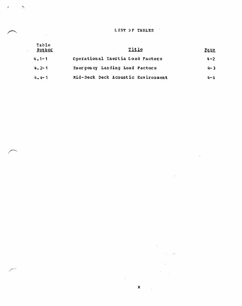
Table l!Y.mJ~~
4.1-1
4.2-1
4.4-1
LIST ) F TABLES
Operational Inertia Load Factors 4-2
Emergency Landing Load Factors 4-3
Mid-Deck Deck Acoustic Environment 4-6
x

Figure Number
3.1.1-1
3.2.1-1
3.2.1-1
3.2.1-1
3.3.2-1
3.3.2-1
3.4.1-1
3.4.2-1
3.4.2-2
3.5.1-1
3.5.2-1
3.5.2-2
3.5.2-3
3.5.3-1
3.5.3-2
3.5.4-1
3.5.5-1
3.5.6-1
3.7-1
3.11.2-1
LIST OF FIGURES
Title
Orbiter Crew Module Coordinate System
physical Interface Location Overview (Sheet 1 of 3)
Physical Interface Location Overview (Sheet 2 of 3)
Physical Interface Location Overview (Sheet 3 of 3)
Mid-Deck Modular Locker Layout (Sheet 1 of 2)
Mid-Deck Modular Locker Layout (Sheet 2 of 2)
Standard Mid-Deck Modular Locker
Large Stowage Tray
Small Stowage Tray
Single Adapter Plate
DOUble Adapter Plate
Method of Attachment Double Adapter Plate to Wire Trays
Alternate Method of Attachment Double Adapter Plate to Wire Trays
Payload Mounting Panel
Method for Mounting Payload-to-Payload Mounting Panel
Payload/STS Attachment Point Details
MOdified Locker Access Door
Diagram of DC Cable
Payload/GSE Hard Points
Power Provisions at Mid-Deck Ceiling Location (Sheet 1 of 3)
xi
Page
3-7
3-8
3-9
3-10
3-11
3-12
3-13
3-14
3-15
3-16
3-17
3-18
3-19
3-20
3-21
3-22
3-23
3-24
3-25
3-26 "\ I

Figure Number
3.11.2-1
3.11.2-1
4.1-1
4.1-2
4.1-3
4.6.2.1-1
4.6.2.2-1
5.2.2.1-1
5.2.2.1-2
6.2.2-1
6.2.2-2
6.2.2-3
7.6.2-1
7.6.2-2
," "" ,~ .
: 7 ~ of' ."."
LIST OF FIGURES
Title
Power Provisions at Mid-Deck Ceiling Location (Sheet 2 of 3)
Power Provisions at Mid-Deck Ceiling Location (Sheet 3 of 3)
Directions of Load Factors
Transient Response at Lift-off
Transient Reponse at Landing
Maximum Payload Weight and Center-of-Gravity for Single Adapter Plate
Maximum Payload Weight and Center-of-Gravity for Double Adapter Plate
Maximum Allowable Heat Load for a Cabin Pressure of 14.7 psia
Maximum Allowable Heat Load for a Cabin Pressure of 10.2 psia
Transient Surge of DC Voltage Step Function Loci Limits During Normal Equipment Switching Conditions
Transient Surge of DC Voltage Step Function Loci Limits During Abnormal Switching Conditions
Transient Surge of DC Voltage Step Function Loci Limits During Emergency Switching Conditi ons
Shuttle-Produced Radiated Broadband Emissions, Unintentional
Shuttle-Produced Radiated Narrowband Emissions, Unintentional
xii
3-27
3-28
4-7
4-8
4-9
4-10
4-11
5-4
5-5
6-4
6-5
6-6
7-4
7-5

Figure Number
7.6.2-3
7.6.3.1-1
7.6.3.1-1
7.6.3.1-2
7.6.3.1-3
7.6.3.2-1
7.6.3.2-2
8.2.1-1
LIST OF FIGURES
Title
Shuttle-Produced Radiated Narrowband Emissions, Intentional
Payload Allowable Conducted Narrowband Emissions (Sheet 1 of 2)
Payload Allowable Conducted Narrowband Emissions (Sheet 2 of 2)
Envelope of Payload Allowed Transient Spikes on DC Power Busses for Normal Electrical System Operation
Envelope of Payload Allowed Transient Spikes on DC Power Busses for Abnormal Electrical System Operation
Payload Allowable Radiated Broadband Emissions
Payload Allowable Radiated Narrowband Emissions
Plug Assignments at Ceiling Locations
xiii
.~.
7-6
7-8
7-9
7-10
7.~11
7-12
7-13
8-3
-"
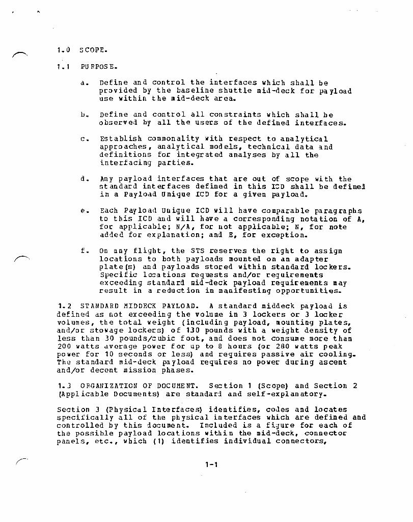
1.0 SCOPE.
1 • 1 PU R POS E.
d. Define and control the interfaces which shall be pr~vided by the baseline shuttle mid-deck for pa yload use within the mid-deck area.
h. Define and control all constraints which shall be observed by all the users of the defined interfaces.
c. Establish commonality ~ith respect to analytical approaches, analytical models, technical data and definitions for integrated analyses by all the interfacing parties.
d. Any payload interfaces that are out of scope with the st andard int er faces defined in this 1:0 shall be definel in a Payload Unique rCD for a given payload.
P.. Each Payload Unigue ICD will have comparable paragraphs to this leD and will have a corresponding nota tion of A, for applicable; NIA, for not applicable; N, for note added for explanation; and E, for exception.
f. On any flight, the STS reserves the right to assign locat ions to bot h pay loads mounted on an adapter plate(s) and payloads stored within standard lockers. specific lo=ations reguests and/or reguirements exceedin g standa rd mid -deck payload regui[" ements may result in a reduction in manifesting opportunities.
1.2 STANDARD MIDDECK PAYLOAD. A standard middeck payload is defined as not exceeding the volume in 3 lockers or 3 locker volumes, the total weight (including payload, mounting plates, and/or stowage lockers) of 130 pounds with a weight density of less than 30 poundsl=ubic foot, and does not consume more than 200 watts ~verage power for up to 8 hours (or 280 watts peak power for 10 seconds or less) and reguires passive air cooling. The standard mid-deck payload requires no power during ascent andlor decent mission phases.
1.3 ORGANIZATION OF DOCUMENT. Se=tion 1 (Scope) and Section 2 (Applicable Documents) are standari and self-explanatory.
section J (Physical Interfaces) identifies, codes and locates specifically all of the physical interfaces which are defined and controlled by this do=ument. Included is a figure for each of the possible payload locations within the lIIid-deck, connector panels, etc., which (1) identifies individual connectors,
1-1
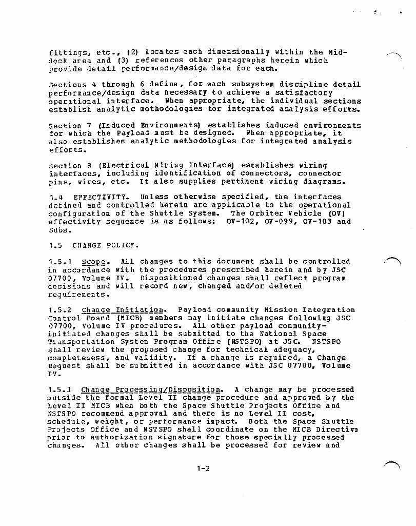
fittings, etc., (2) locates each dimensionally within the l1iddeck area and (3) references other paragraphs herein which provide detail performance/design 'lata for each.
sections 4 through 6 define, for each subsystem discipline detail performance/design data necessary to achieve a satisfactory operational interface. When appropriate, the individual sections establish analytic methodologies for integrated analysis efforts.
section 7 (Induced Environments) establishes induced environments for which the Payload must be designed. When appropriate, it also establishes analytic methodologies for integrated analysis efforts ..
section 8 (Electrical Wiring Interface) establishes wiring interfaces, including identification of connectors, connector pins, wires, etc. It also supplies pertinent wiring diagrams.
1.q EFFECTIVITY. Unless otherwise specified, the interfaces defined and controlled herein are applicable to the operational configuration of the Shuttle System. The Orbiter Vehicle (OV) effectivity sequence is as follows: OV-102, OV-099, OV-103 and subs.
1.5 CHANGE POLICY.
1.5.1 ~E.~. in accordance 07700, Volume decisions and requirements.
All with IV. will
changes to this document shall be controlled the procedures prescribed herein and by JSC Dispositioned changes shall reflect program record new, changed andlor deleted
1.5.2 Cha~~_!Rii~~~i2B. Payload community Mission Integration Control Board (MICB) members may initiate changes following JSC 07700, Volume IV pro=eJures. All other payload commanityinitiated changes shall be submitted to the National Space Transportation System Program Offi:: e (NSTSPO) at JS C. NSTSPO shall review the proposed change for technical adequacy, completeness, and validity. If a =hange is reJuired, a Change Request shall be submitted in accordance with JSC 07700, Volume IV.
1.5.3 Cha~~-R£Q£g§~!llgL~!§£Qsit!Q~. A change may be processed outside the formal Level II change procedure and approved by the Level II MICB when both the Space Shuttle Projects Office and NSTS PO recommend a pproval and there is no Level II cost, schedule, weight, or performance impact. Both the Space Shuttle Projects Office and NSTSPO shall coordinate on the MICB Directiv3 prior to authorization signature for those specially processed changes. All other changes shall be processed for review and
1-2
f,

appropriate disposition action as specified by JSC 07700, Volume IV.
1-3

2.0 DOCU C1ENTS.
2.1 APPLICABLE DOCUMENTS. The following documents of the exact issue shown shall form a part of this document to the extent specified herein. In the event of conflict between the documents referenced and the contents of this document the contents of this document sh all be con sidered a superseding rp.guirement. Befer:ence paragraphs listed refer to this ICD.
M1 L- 13- S087B (Cur:ren t. IssIJ e)
iiI L-C- 5541 (Curr:en t ISSll e)
SN-C- 0005 (Cur:rent Issue)
SE- S- 0073 Pebr:uary 14, 1977
tiS PC- 40 M38277 (Curren t Issu e)
MSFC- 40M39569 (Curren tIssue)
Bonding, Electrical and L igh tni ng Protection for Aerospace Systems
Ref. Par3.. 6.4.8,7.6.4.2,7.6.4.2.2.1, 7.6.4.2.3
Chemical Conversion :oatings on Aluminum and Aluminum Alloys
Ref. Pan .• 7.6.4.2
Specific3.tion, Contamination Control Reguirements for the Space Shuttle Program
Ref. Pan .• 5.2.1.6, 7.7
Specification, Space Sh ut tleFI uid Procurement and (J se Control
Ref. Para. 5.2.1.2
Connectors, Electrical, Circular Miniature, High Density, Environment Resisting, Specification for
Ref. Pa r3. • 2. 4, 8. 1. 2
Connectors, Electrical Miniature Circular, Environment Resisting 200oC, Specification for
Ref. Pan. 2.4, 8.1.2
2-1

NIIB1700.7 (Cueren tIssue)
JSC- SE- R- 0006 B (curren tIssue)
NIl il- 8060. 1 (Curren tIssue)
2.2 REFERENCE DOCUMENTS.
JSC 07700 Vol. IV
JSC 07700 Vol. XIV
JSC SC-A-0004B
Safety Policy and Requirements for Payloads Using the Space Transportation System
Ref. Para.. 7.8
General Specifications NASA JSC Requirements for Materials and Processes
Ref. Para. 7.8
Flammability, Odor and Off-Gassing Requirements and Test Procedures for Materials dnd Environments that Support Combustion
Ref. Para. 7.8
Sp ace Shu t tle Program, Le vel II P rog ram Definition and Requirements, Configuration Management
Spdce Shuttle Program, Level II Program Definition and Requirements, Space Shuttle System Payload Accomod ations
Abbreviations, Manned Spacecraft· and Related Flight Crew Equipment
2.3 R OCKW ELL I NTE RNATION AL DRAWING SAND SPECIPICA TIONS. All part numbers listed in this leD beginning with the following prefixes V-602, V-646, V-070 or V-733 and all specification numbers beginning with the following letters MC, MD or ME are Rockwell Inter-national Company documents.
2.4 INTERN ATIONAL LAT EX CORPOR ATIJ N (ILC) DRAWING S. All part numbers listed in this leD beginning with the following number~) 10108-XXXXX are ILC drawings.
2.5 ELECTRICAL CONNECTOR PART NUMBERS. All electrical connectors with part number prefixes NBO or NBG are listed in MSFC-40M38277 or MSFC-40M39569 Specifications.
2-2

3.0 PHYSICAL INTERFACES.
3.1 GEOMETRIC RELATIONSHIPS.
3.1.1 co~£dillate~Y2te~2·
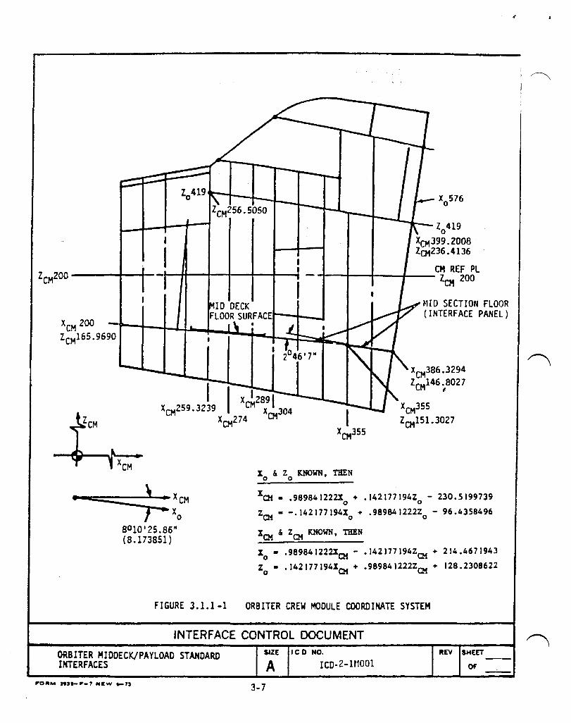
3.1.1.1 Or bit er Cr ew Module (CM). T he Orbiter crew mod ule coordinate system shall be in conformance with Figure 3.1.1-1 and as follows:
Origin:
orientation:
Characteristics:
In the Orbiter crew module plane of symmetry, 200 inches below the crew module re ference plane and at crew mod ule X station o.
The Xcm axis is in the crew mod ule p lane of sy mmetry, pa rallel to and 200 inches below the crew module reference plane. Positive sense is from the nose of the vehicle toward the tail. The Z em axis is the crew module plane of symmetry, perpendicular to the Xcm axis posit ive upward in landing a tti tude.
The YCII axis completes a right hand system.
Rotating right-handed cartesian. The standard subscript is CM (E. G. Xcm).
3.2 INTERFACE LOCATION AND DIMENSIONING.
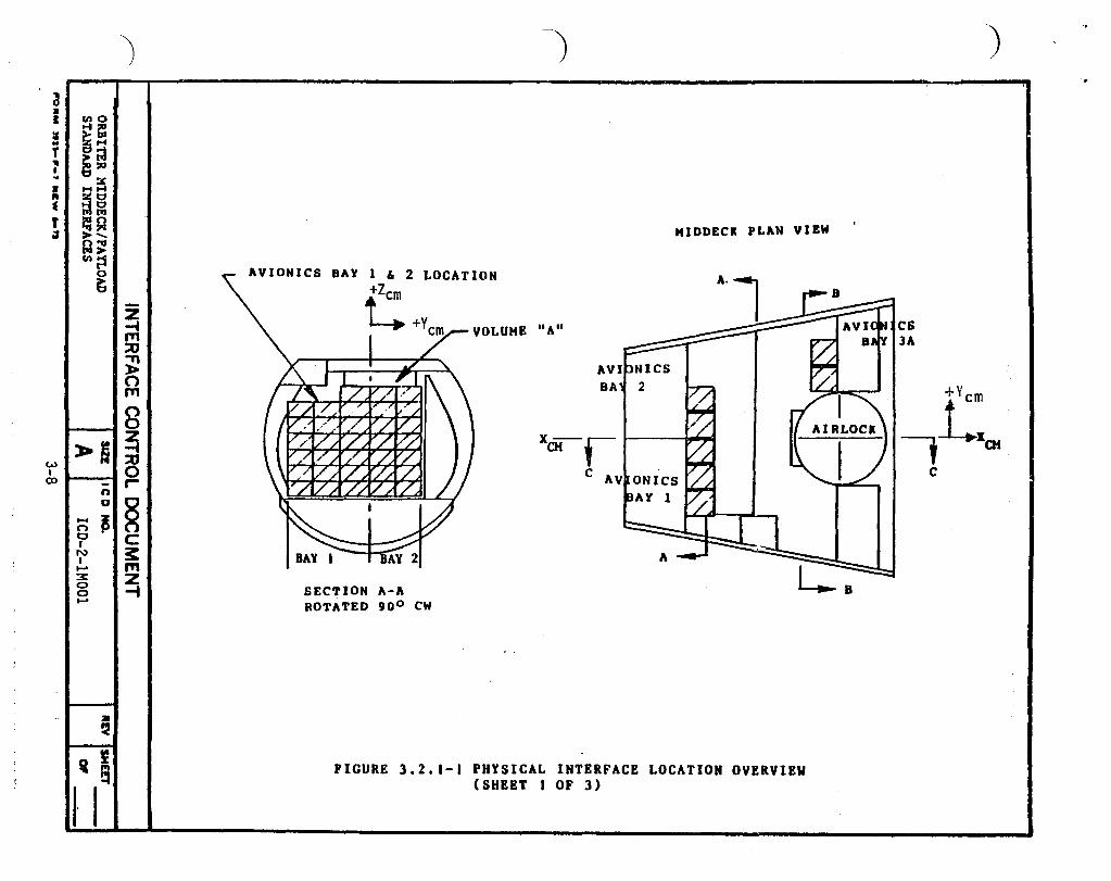
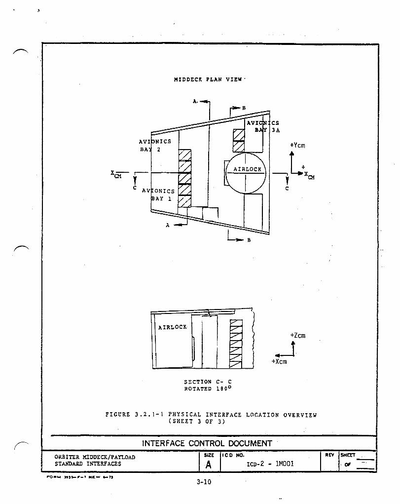
3.2.1 .mu§.ic&Jll!:.~.f~~ Lo,£ations. Shuttle Orbiter MidDeck/Payload interface locations shall be in accordance with Figure 3.2.1- 1.
3.2.2 ~imgll2iQn§~llg-I2!g£~~'£~§. Unless otherwise specified all linear dimensions are in inches, all angular dimensions are in degrees, and the tolerances for these are as follows:
Decimal: x.x = ±0.1 x.xx = to.03 x.XXX = ±0.010
Fractions: ±1/16
Angles: ±oo30 •
3.3 STRUCTURAL INTERFACES. There are 3 locations for attaching payloads in mid-deck area as follows:
3 -1

....
a. Aft surface of wire trays of Avionics Bays 1 and 2
b. Forward surface of wire trays of Avionics Bay 3A
c. volume It A", 10 cated above A v ionics Bay 1 and 2
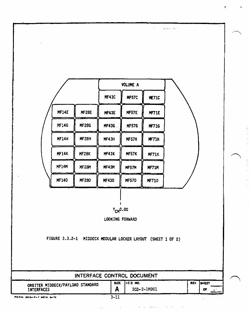
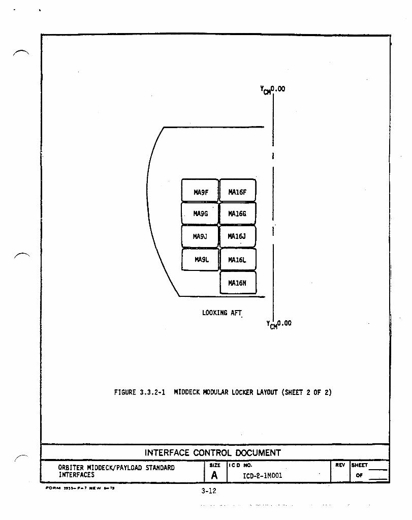
3.3.' ~vioni£2~~I-1~~tio~2. Payloads shall be attached to the surface of the wire trays forming bulkheads of Avionics Bays No. 1, 2 and 3A as shown in Figure 3.3.2-1. Availability of specifi::: locations for payload usage is pursuant to mission profile and its length, size of Orbiter crew and amount of crew equipment to be stowed in standard stowage Lockers at this location.
3.3.2 !oly~"A" 12£atiog. Payloads shall be installed in Volume "A", located above the forward mid-deck lockers as shown in Figure 3.3.2-1. This volume accommodates three small stowage trays with guides side by side or provides a clear volume of 5.184 inches high x 20.315 inches deep x 52.02 inches wide with the tray guides removed.
Payl::>ads that cannot be staved inside the small trays shall be stowed di rectl y in this volume, prov ided they are isola ted from vibration contact with the locker and have zero "g" retention for on-orbit activities.
The maximum weight of the locker contents including payload, protective provisions and trays shall not exceed 95 pounds.
3.4 ST ANDARD PAYLOAD PROVISION S. Standard payload provisions shall consist of a standard modular stowage locker and two sizes of standard stowage trays - large and small.
3.4.1 ~tandsrd Mog~l~£-2tows~-kQgke£. Standard Modular Stowage Locker (Figure 3.4.1-1) provides 2 cubic feet of stowage volume.
3-2
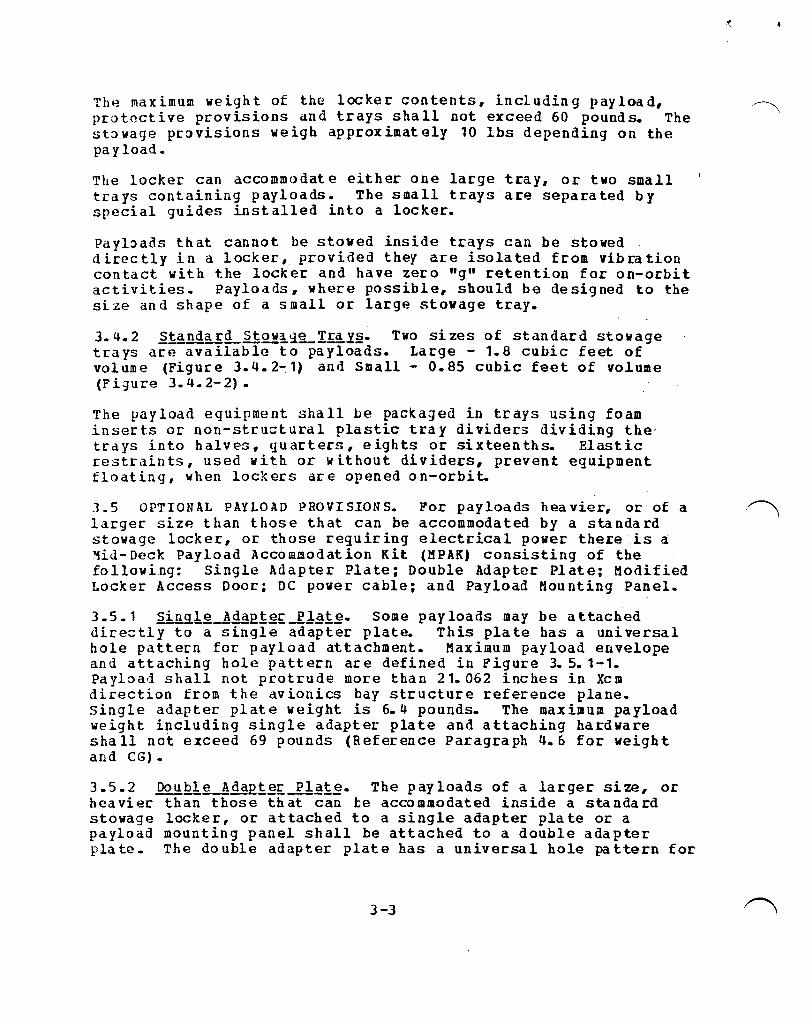
The max imum weigh t of the locke r con tents, inci udin g pay loa d, protective provisions and trays shall not exceed 60 pounds. The stowage provisions weigh approximately 10 lbs depending on the payload.
The locker can accommodate either one large tray, or two small trays containing payloads. The small trays are separated by special guides installed into a locker.
Payloads that cannot be stowed inside trays can be stowed directly in a locker, provided they are isolated from vibration contact with the locker and have zero "g" retention for on-orbit activities. Payloads, where possible, should be designed to the size and shape of a small or large stowage tray.
3.4.2 Standar~StQ!a~~TraI2. Two sizes of standard stowage trays are available to payloads. Large - 1.8 cubic feet of volume (Figure 3.4.2-1) and Small - 0.85 cubic feet of volume (Figure 3.4.2-2).
The payload equipment shall be packaged in trays using foam inserts or non-structural plastic tray dividers dividing the' trays into halves, quarters, eights or sixteenths. Elastic restraints, used with or without dividers, prevent equipment floating, when lockers are opened on-orbit.
].5 OPTIONAL PAYLOAD PROVISIONS. For payloads heavier, or of a /~ larger size than those that can be accommodated by a standard stowage locker, or those requiring electrical power there is a MiJ- Deck Payload Accommodation Kit (MPAK) consisting of the following: Single Adapter Plate; Double Adapter Plate; Modified Locker Access Door; DC power cable; and Payload Mounting Panel.
3.5.1 sin~1~_Ada21~£-lJgl~. Some payloads may be attached directly to a single adapter plate. This plate has a universal hole pattern for payload attachment. Maximum payload envelope and attaching hole pattern are defined in Figure 3. 5. 1-1. Payload shall not protrude more than 21.062 inches in Xcm direction from the avionics bay structure reference plane. single adapter plate weight is 6.4 pounds. The maximum payload weight including single adapter plate and attaching hardware shall not exceed 69 pounds (Reference Paragraph 4.6 for weight and CG).
3.5.2 Doubl~-AdaE£~£ PIg£~. The payloads of a larger size, or heavier than those that can be accommodated inside a standard stowage locker, or attached to a single adapter plate or a payload mounting panel shall be attached to a double adapter plate. The double adapter plate has a universal hole pattern for
3-3 /~

payload attachment. Maximum payload envelope and attaching hole pattern are defined in Figure 3.5.2-1.
Double adapter plate attaches to two single adapter plates or two payload mounting panels installed one above the other to the avionics bay structure interface as shown in Figure 3.5.2-2 or 3.5.2-3. Payloads shall not protrude more than 21.062 inches in Xcm direction from the avionics bay structure reference plane. Double adapter plate weight is 15 pounds and it is attached to either the single adapter plates or the payload mounting panels with STS provided special bolts as noted in Paragraph 3.6. The payloads that use the double adapter plate shall provide clearance for the locker tool to engage these bolts.
The maximum payload weight, including two single adapter plates, one double adapter plate and attaching hardware shall not exceed 120 pounds (Reference Paragraph 4.6 for weight and CG).
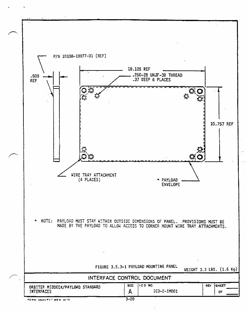
3.5.3 ~aIlqad MOYntin~g~~~!. Payloads may be attached directly to a payload mounting panel, or directly to two payload mounting panels. A double adapter plate may be attached to two payload mounting panels. The hole patterns and mounting methods are defined in Figures 3.5.3-1 and 3.5.3-2. A single payload mounting panel weight is 3.0 pounds. The allowable mounting payload weights and CG locations are the same as the single and double adapter plates.
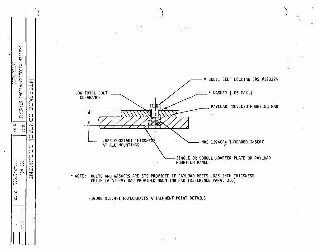
3.5.4 !da~te£_Plat~ In~~£~. The attachment points on the payl~ad for securing to an adapter plate or mounting panel shall be designed per Figure 3.5.4-1. This requirement will allow use of a common STS supplied bolt (SPS #123374 - selflocking), Reference Paragraph 3.6.
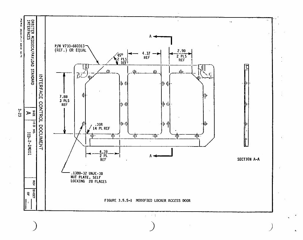
3.5.5 Modified~Q£~~£ AC~§2-YQQf. payloads using standard stowage lockers, but requiring access for power or cooling shall use a modified locker door. Modified locker door has three removable panels, defined in Figure 3.5.5-1. These panels shall be payload supplied.
3.5.6 QC ~able§. STS-provided optional DC cables route DC power from the Orbiter ceiling utility outlets to the payloads. The DC cables contain three conductors and shall interface with the payload through a socket connector. The D: cable is defined in Figure 3.5.6-1.
3.5.7 l!2.y.n.i!n.g-!££S22. When payloads are attached to two single plate (or panels), clearance shall be provided for the locker tool to engage the pd yload mounting" bolts.
3-4
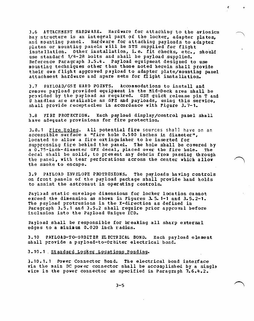
3.6 ATTACHMENT HARDWARE. Hardware for attaching to the avionics .~. bay structure is an integral part 9£ the locker. adapter plates, and mounting panel. Hardware for attaching payloads to adapter plates or mounting panels will be STS supplied for flight installation. Other installation, i.e. fit checks, etc., should use standard 1/4-28 holts and shall be payload supplied. Reference Paragraph 3.5.4. Payload eguipment designed to use mounting techniques other than those noted herein shall provide their own f ligh t approved payload to adapter plate/mounting panel attachment hardware and spare sets for flight installation.
3.7 PAYLOAD/GSE HARD POINTS. Accommodations to install and rellove payload provided equipment in the Mid-Deck area shall be pr~vided by the payload as required. GSE quick release pin T and U handles are available as GFE and payloads, using this service, shall provide receptacles in accordance with Figure 3.7-1.
3.8 Fl BE PROT EcrlON. Each pay load display/control panel shall have adequate provisions for fire protection.
3.8.1 Fi~[ol~. All potential fire sources shall have on an acces$ible surface a "fire hole 0.500 inches in diameter", loca ted to allow a fire ext lngu isher to be inse rted for suppressing fire behind the panel. The hole shall be covered by a O.75-inch-diameter GFE decal, placed over the fire hole. The decal shall be solid, to prevent any debris from passing through the panel, with tear perforations across the center which allow ~ the smoke to escape.
3.9 PAYLOAD ENVELOPE PROTRUSIONS. The payloads having controls on front panels of the payload package shall provide hand holds to assist the astronaut in operating controls.
Payl:> ad static envelope dimensions for locker loea tion ca nnot exceed the dillension as shown in Figures 3. 5. 1-1 and 3.5.2-1. The payload protrusions in the X-direction as defined in Paragraph 3.5.1 and 3.5.2 shall require prior approval before inclusion into the Payload Unique LCD.
Payload shall be responsible for breaking all sharp external edges to a minimum 0.020 inch radius.
3.10 PAYLOAD-To-ORBITER EL ECTRICAL BOND. Each payload element shall provide a payload-to-orbiter electrical bond.
:l.10.1.1 Power Connector Bond. The electrical bond interface via the main DC power connector shall be accomplished by a sing13 wire in the power connector as specified in Paragraph 7.6.4.2.
3-5
. r-'.
3.10.1.2 Payload to STS Supplied Mounting Surface Bond. The structural bond path shall conform to the require.ents specified in Paragraph 1.6.4.2.
3.11 POWER PROVISIONS.
3.11.1 Mig~]~£~_£~i!!~ Lo£atjgn. Power interfaces at Kid-Deck Ceiling Locations shall be as shown in Figure 3.11.2-1.
3.11.2 Cab l!L!!.QYli n!l. Cable routing shall be defined in Crew compartment control drawing for tha specific mission incorpo rating the pay load.
3.12 NOMENCLATURE. To ensure standardization of the nomenclature used on payloads with that of the Orbiter, the payl~ads shall use where possible the abbreviations listed in SCA-OOO 4 R •
3-6
• ; : XCM
Xo
8°10'25.86" (8.173851)
FIGURE 3.1.1-1
Z0419 X(M399.2008 Z(H236.4136
-t--+---If--_-I-__ CH REF PL ZeM 200
X & Z KNOWN. THEN o 0
HID SECTION FLOOR (INTERFACE PANEL)
XCM386.3294 ZCM146 ;8027
X(H355 ZCM151.3027
XCH •• 9898412221 + .142177194Z - 230.5199739 o 0
ZCH • -.142177194Xo + .989841222Zo - 96.4358496
XCH & ZCM KNOWN, THEN
Xo • .9898412221CH - • 142177194ZCH + 214.4671943
Zo • • 142177 1 94XCH + .989841222ZCH + 128.2308622
ORBITER CREW MODULE COORDINATE SYSTEM
INTERFACE CONTROL DOCUMENT
ORBITER MIDDECK/PAYLOAD STANDARD INTERFACES
SIZE leo NO.
A ICO-2-lt1001
3-7
REV SHEET
or --
a • I
II .. T .. I .. • .. • , II
cnO
~e 5a ~
HH
a~ i:g~ >-fJi: cnri
o ~
')
z ;;t :0
~ o ."
..-.8 >~~
w r;r:o ~ 0 n ,-
~ ; ~ rr c ~ :s:: ..... ." ~ Z S -t
a ~
'i ~
I· I
AVIONICS BAY 1 & 2 LOCATION +Zcm
)
t: +Ycm VOLUME IIAII
SECTION A-A ROTATED 900 CW
BA
XCH,
C AV
MIDDECl PLAN VIEW
L.:B
FieURE 3.2.1-1 PHYSICAL INTERFACE LOCATION OVERVIEW (SHEET 1 OF 3)
)
tm , XCH
C

... 0 :II r ¥ .. 'r ,. I .. I ~ , t OJ
w I ~
(1)0 o-t~ ~H 5~ ~ §~ .. I:) M
i::R ). ..... n'll 1'1> II)~
~
))o~ ... -0 0
~ H
9 I
:.,.,
..... ::s:: 0 0 .....
;III
~
~ ~ !:I I ,.
1-Z -t rt1 ::01 ."
BA > (") rt1
~I xCMf-
C AV ::0 0 r
g C :c rn Z
.-i
)
HIOO~CK PLAN VIEW
+Ycm
,hxCH c
L:o
AVIONICS BAY 3A LOCATtON +Zcm
Ycw=o SECTION D-a
ROTATED 90 0 CCW
FIGURE 3.2. I-I PHYSICAL INTERFACE LOCATION OVERVIEW (SHEET 2 OF 3)
)
......
...
)
~. (
HIDDEC~ PLAN VIEW'
BA
x - r- i---... ..,.. eM l
c AV
AIRLOCK
SECTION c- C ROTATED 1800
CS 3A
+Ycm
+Zcm
.-1. +Xcm
FICURE 3.2.1-1 PHYSICAL INTERFACE LOCATION OVERVIEW (SHEET 3 OF 3)
ORBI1"£R KIDDECK/PAYLOAD STAlI"DAB.D Ui'TI:RF ACES
INTERFACE CONTROL DOCUMENT SIZE Ie D NO.
A ICD-2 - 1M001
3-10
REV SHEET
. OF
. , ,
VOLUME A
HF43C MF57C ME71C
I MF14E MF28E MF43E MF57E MF71E
HF14G HF28G HF43G . HF57G HF71G
HF14H MF28H MF43H MF57H MF71H
HF14K HF28K HF43K MF57K MF71K
HF14H HF28M MF43M MF57M MF71M
HF140 HF280 HF430 MF570 MF710
I I
YCMo.ao
LOOKING FORWARD
FIGURE 3.3.2-1 HIDDECK f«>DULAR LOCKER LAYOUT (SHEET 1 OF 2)
INTERFACE CONTROL DOCUMENT
ORBITER MIDDECK/PAYLOAD STANDARD SIZE ICD NO. IlEV SHEET -INTERFACES A ICD-2-1MOOl Of • -3-11
~
YQ40.00
MA9F MA16F
MA9G MA16G
MA9J MAl6J I
MA9L MA16l
MA16N
LOOKING AFT YCMO.OO
FIGURE 3.3.2-1 MIDDECK MlDULAR LOCKER LAYOUT (SHEET 2 OF 2)
INTERFACE CONTROL DOCUMENT
ORBITER MIDDECK/PAYLOAD STANDARD INTERFACES
SIZE leD NO.
~ ICD-2-1M001
3-12
i I I I
I
REV SHEET
OF

PIN V602-66J604
n'Rtx:"1'URAL AT'1'ACB FASTENERS
I NSTL/REMOVAI, TOOL CUIDES
NOTES:
20.320 (INSIDE)
ct,
17 .312 R,EF (INSIDE)
FRIe:nOM 17\ RINGE 0
1 • MODULAR LOCKER BAS A MAXIMUM DESIGN DENSITY OF 30 LBS/FT3 , AND A KINIMtIH OF 10 LBS/FT3
2. BASELINE LOCKERS ARE DESIGNED TO THE FOLLOWING CllITERIA o THE LOCKER IS PACKED SOLID. o THERE MUST BE ISOLATOR MATERIAL BETWEEN THE LOCKER WALLS AND THE
CONTENTS o THE ISOLATOR MA'!'ERlAL (PYRELL OR SIMILAR MATERIAL) SHALL HAVE A
THICKNESS AND MODULUS OF ELASTICITY COMBINATION ESTABLISHED BY DESIGN WICH WII.L PROVIDE A SPRING-RATE OF 22,000 LB/IN OR LESS
3. DOOR IS nuSH WITH BOTTOM OF LOCKER WEN OPENED 900 DEGREES AND CAN OPEN 180 DEGREES (STRAIGHT DOWN). o 4. DOOR HAS FRICTION· HINGE FOR ZERO-G OPERATION AND A MAGNETIC LATCH FOR
TEMPORARY CLOSURE OF DOOR.
FIGURE 3.4.1-1 STANDARD MIDDECK MODULAR LOCKER
INTERFACE CONTROL DOCUMENT
ORBITER MIDDECK/PAYLOAD STANDARD INTERFACES
P'O ... _ ... ,,_, __ .. ,.
a&ZE ICO NO.
~ ICD-2-1M001
3-13
JtlV SHUI'
F 011 -
~.

I
<4-;91 ~I: !,.030 ,
DETAIL A
(TYP. 4 CDR~IERS)
DETAIL A
PT IME192-0070-0002
FIGURE 3.4.2-1 LARGE STOWAGE TRAY
INTERFACE CONTROL DOCUMENT
ORErlER MIDDE:~/PAYLOAD STANDARD llITERFACES
SIZE leo NO.
A ICD-2-1M001
3-14
REV SHEET
OF

.91 I +.03d - I
DETAIL A (TYP. 4 CORNERS)
,----- PT 1ME192-0070-0001
FIGURE 3.4.2-2 SMALL STOWAGE TRAY
INTERFACE CONTROL DOCUMENT ORBITER MIDDECK/PAYLOAD STANDARD INTERFACES
SIZE ICD NO.
~ leo· 2-1M001
3-15
., 4.64 IN. INSIDE t REF
REV SHEET
OF

PIN V733-660310 (REF.) OR EQ~AL PAYLOAD ENVELOPE
~-------18.125 REF -------:~~I
I ;::I>. ..... .
*
$ $ 10.757 REF
.2500-28 UNJF-38 THREAD PER MIL-S-8879
.375 DEEP 15 PLACES
* NOTE: ?AYLOAD MUST STAY WITHIN THE OUTER DIMENSIONS OF THE PLATE. PROVISIONS HUST BE MADE BY THE PAYLOAD TO ALLOW ACCESS TO CORNER MOUNTING WIRE TRAYS ATTACHMENTS.
FIGURE 3.5.1-1 SINGLE ADAPTER PLATE
WEIGHT=6.5-Lb (3.09 kg)
INTERFACE CONTROL DOCUMENT
ORSliER HIDDECK/PAYLOAD STANDARD ISTERFACES I
SAIZE ICO NO.
ICD-2-1MOOl
3-16
REV SHEET
OF

DOUBLE ADAPTER PLATE ATTACHMENTS (4 PLACES)
REFERENCE PARAGRAPH
3.5.2
21.882 I
REF
PAYLOAD ENVELOPE *
'- .2500· .. 28 UNJF-3B I· . . THREAD PER
I Q.) - - - - - - - - - - - - - - - - - - - --
MIL-S-8879) .375 DEEP, 22 PLACES
(MDl15-2002-0004) .875
'f-]- - ;N-V7~3-660311 (REF) OR EQUAL
* NOTE: PAYLOAD MUST STAY WITHIN THE OUTER DIMENSIONS OF THE PLATE. PROVISIONS MUST BE MADE BY THE PAYLOAD TO ALLOW ACCESS TO CORNER MOUNTING WIRE TRAY ATTACHMENTS.
FIGURE 3.5.2-1 DOUBLE ADAPTER PLATE WEIGHT=14.4 Lb. (6.55 kg)
INTERFACE CONTROL DOCUMENT
ORS:TER M!DDEC~/?AYLOAD SiANDAR~ I Ii7ERF AC ES
i ~r )1 C 0 He
i A: leD- 2~lMOOl
3-17
R~" IS,",::r7 __ ! I or -.
.~
.. ~

'I 0 :w J:
~ .. T 'I I ., z 1'1 S
f .. ..
CAl I ~ (»
.... 0
~E i:ltJ >:oa n M:J: til ....
l:I 0 ''I Q ..... '" >-~ ~ I/)
)!
~
')
Z -I rn :0
" » () rn ()
1---11 0 Z -I :0
»lS ,....
ng~ ~ () .... 9 I
N I ~ 3: o o ......
:II
~
(II
o J:
I"I~
C s: rn Z -I
')
r- d 4U
It I .. J ~ ~-
BOLTS ATTACHING DOUBLE PLATE TO SINGLE PLATE
HD1l2-3002-0412 OR EQU1l.L 4 REQUIRED (STS SUPPLIED)
)
DOUBLE ADAPTER PLATE
]~Z?(
SINGLE ADAPTER PLATE
FIGURE 3.5.2-2 METIIOD OF ATTACHMENT DOUBLE ADAPTER PLATE TO WIRE TRAYS

0 ;u I" I· •
;,11 :;u
3: t-t
0 t-.. t.:J ;;: '11 -In II' 7: ;0,
-11 " )::>)::> C) -< It, r- Z VIO --I )::>
'-' III Vl :U -I
~ -1",
0 ~ ).> ( ) ;0 r, III
( )
w _u I
1 .. 1 z .... \0 i; -I
... :lJ () r-
...... t-t (")n U C:J t:J I 0 I" 2: I 0 () ~.
3: L 0
~: 0 .-~
rn Z -I
w I
1-& \0
---.11 "1
', . 0, . 1.
"I 0'1 ,
I I
I
)
, :\ '0 ,'-----II ,.
/ ~ ',ly I ,
I t
\ I
BOLTS ATTACHING I DOUBLE PLATE TO PAY-\ LOAD MOUNTING PANEL , SPS #123374 (SELF LOCKING) OR I
I EQUAL 4 REQUIRED ( I (REF PARA 3.6)
, I J ~-:::: -=-- -:.::-:::: =- = = -:... -- -------..:: -= -.:. -:.,----: -= = --------
~-~II 11--...1 I
~ @ ~ ) ,,----Itd' 6.JI---r
l t,,, - - _/ -/) f
PAYLOAD _--..l
FIGURE 3.5.2~1 ALTERNATE METHOD OF ATTACHMENT DOUBLE
ADAPTER PLATE TO WIRE TRAYS
)-
\
\
J (
(
l
DOUBLE ADAPTER PLATE
PAYLOAD MOUNTING PANELS
WIRE TRAY STRUCTURES
)
r--. !
~ PIN 10108-10077-01 (REF)
R~~O ~ r- " . / . \~ O)I{i)7-- ----
-O-~ ~ I , ., , .'
18.125 REF .250-28 UNJF-38 THREAD .37 DEEP 6 PLACES
: ~~ ,--
10.757 REF
-- ---- - ---- ------ ~~ \ .-.L...
WIRE TRAY ATTACHMENT (4 PLACES) * PAYLOAD
ENVELOPE
* NOTE: PAYLOAD MUST STAY WITHI~ OUTSIO~ OIM~NSIONS OF PANEL •. PROVISIONS MUST BE MAD=: BY TH=: PAY!..OAD TO ALLOh' ACCESS TO CORNER MOUNT WIRE TRAY ATTACHMENTS.
FIGURE 3.5.3-1 PAYLOAD MOUNTING PANEL
INTERFACE CONTROL DOCUMENT
ORBITER MIDDECK/PAYLOAD STANDARD Ih1'ERFACES ,
. SIZE II C 0 NO.
A ICD-2-1MOOl
3-20
WEIGHT 3.3 LBS. (1.5 Kg)
SHEET
OF

0"'---- - - --- - - - -- - -''0 ~ ,~ ~~ ~I
:\.- - - - - - - - - - - - - - - - -
I I I I I f I f
~~ I .... .»'
/6
I (' \---, r \ J (
\ I l l--\
'- --
BOLTS ATTACHING PAYLOAD WIRE TRAY ---' '--- TO PAYLOAD ~lOUNTING PANEL STRUCTURES
SPS #123374-SELF LOCKING OR EQUAL 4 REQUIRED (REF PARA. 3.6)
FIGUR~ 3.5.3-2 M~THOD FOR MOUNTING PAYLOAD
PAYLOAD
PAYLOAD MOUNTING PANEL
____________________________ -~T~O_D~~~Y~L~OA~C_· ~M~~U~~~T~rN~;G_p~A~N~:~~~ ______________________ ~~~
Ir ·----A-- ---~~-,....-.,I --- "'-N''.'=;.-.\_:' _ .... 'I\ir--,L __ :,-,~_i\,:-:" I
I:~ NO. ::;:~R=A::5 :::·-:-l'·DO:· 3-21 _________________________________ 3-21 ~ ____________________ ~ _____ . ____ ~
=-t "' ;\1 'II l'> C' ) 1" (/1
w .. N N
( )
'. )
• '" • .-: -'.. 0 C) .. , w • N N
. ,
I
C) :q lJl ... -t ". :",
-'. ...... CJ t~ ". n , .
Z ........ '"0 -I ):> -< 111 1--0 :U ~ -II Cl
V1 P -t ( )
~ III u ;r-.
( ) ;0 f' U
'''12 .. -I :.: ~,
U r-' 1...)
U n
..... L ( ') ;:.:'" t .J ... ,,! ...
7- rn Cl Z
-I
." '"
," .I . III "~I •
I
)
.06 TOTAL OOLT CLEARANCE
.625 CONSTANT TIIICKNE AT AlL MOUNTINGS
')
_-~ BOLT, SELF LOCKING S~S #123374
* WASHER (.05 MAX.)
______ pAYLOAD PROVIDED MOUNTING PAD
NAS 1394CA, THREADED INSERT
SINGLE OR DOUBLE ADAPTER PLATE OR PAYLOAD MOUNTING PANEL
* NOTE: BOLTS AND WASHERS ARE STS PROVIDED IF PAYLOAD MEETS .625 INCH THICKNESS CRITEP.IA AT PAYLOAD PROVIDED MOUNTING PAD (REFERENCE PARA. 3.6)
FIGURE 3.5.4-1 PAYLOAD/STS ATTACHMENT POINT DETAILS
)
~ .... 0 JI ::!i;U t rT1~ ~ ;u-I .. ....., .... r ~;U " r ... :c I Vt .... " ~ Z 1'1 ~
f ;J
o PI ~ "U > -< r-~ o Vt
i1z > -t ~ rn
:0 '"Tl » () rn
~8
w z ~ »~ -t w ,.,:0
o n r-o 0 z
..... 0 n ~ I N I ..... ~ o .....
::0
~
III o :r ... ,.,
!:l
I': 1
)
o () c s:: rn Z -t
AI PIN V733-660313~ 1 (REF.) OR EQUAL /.45
11 .. _ 4.37-
/ REF /\2 PlS
,/ REF
;]7~-r/~-- L-ll> q>
r~ 2PlS1 _ REF I
I--*--::r~~, r ,I/,- (
T -'1) qL (p~1 i) d
<t •. 7.88 3 PlS
REF 1> ~<I. ,
I .31R
14 PL REF 'I) 1 ,.1> 1
~ (tl '-:-QT -- .
.1380-32 UNJC-30 NUT PLATE, SUF LOCKING 20 PLACES
A..... I
L ---
FIGURE 3.5.5-1 MODIFIED LOCKER ACCESS DOOR
)
.. 106'1_ 4
II
II
SECTIOU A-A
) ..

') ') ) r r I
~ • I .... 0 :I ~~ .. T
,., ..... ::0-4
'II ,. ,., I )10::0 .. n • ,.,:.: .- In ....
f 8 f
,., n .. ~ .. -a > -< r-0
~
~12 RECEPTACLE/SOCKET > -I RECEPTACLE/PINS NBOE14-12SNT z ", ~ ;:0 NBOEl4-12PNT2 PLUG/PINS NB6GE14-12PNT2 ~ ""11 » PLUG/SOCKET NB6GE14-12SNT2
0 ",
~IORBITER 0
W~O ----------" ------- - POWER
I 2 :, INTERFACE
N >!!!-I 3-CONDUCTOR ~ ::::;:0
0 AS REQUIRED FOR LOCATION - r-n COVERING STRAIN RELIEF
1-4 0 § 9 ! . . N C I ~ ~
03: ", 0
~ 0 ~
I FIGURE 3.5.6-1 DIAGRAM OF DC CABLE
:. ~ -
~ ! ,(
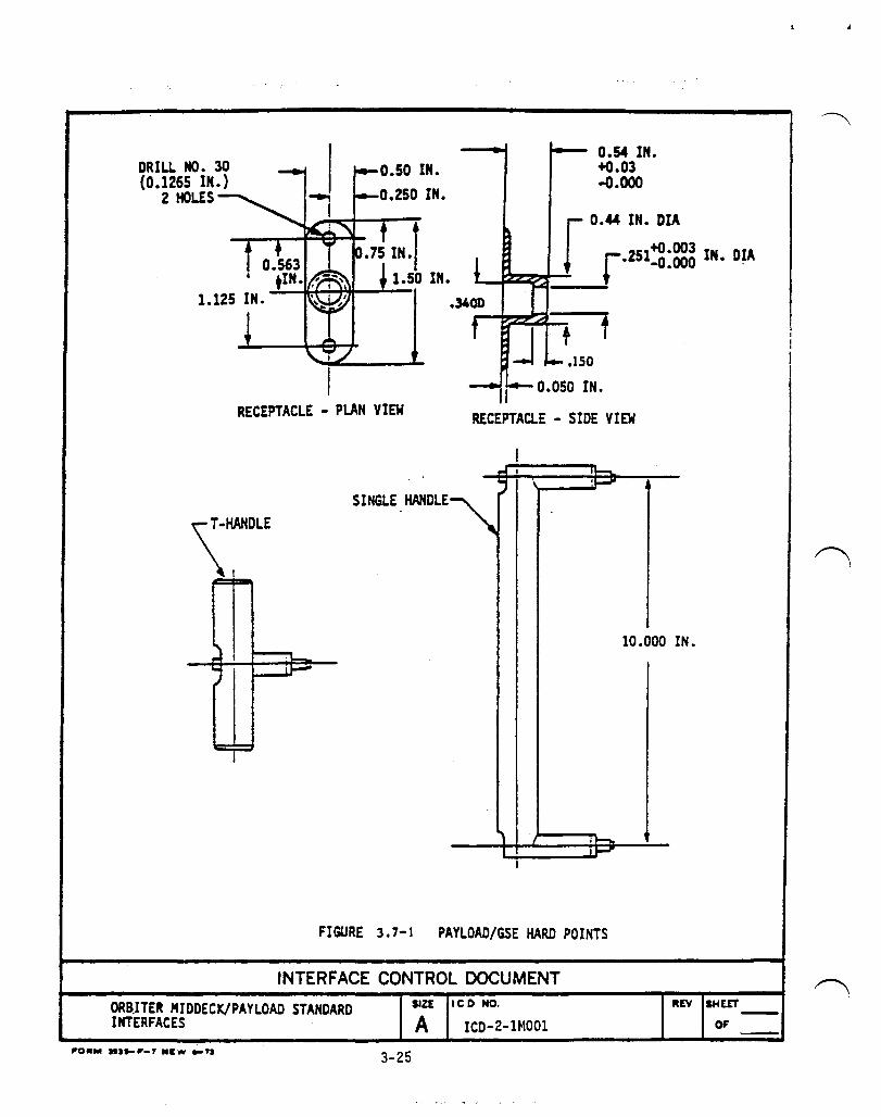
DRILL NO. 30 (0.1265 IN.)
2 HOLES
0.54 IN. +0.03 -0.000
r 0.44 IN. DIA
L.ft2~I-~jr .251~:~ IN. D~
0.050 IN. RECEPTACLE - PLAN VIEW RECEPTACLE - SIDE VIEW
-""'- ,-SINGLE HANDLE ",';J \ ~..-
1 ,~
I I .......
FIGURE 3.7-1 PAYLOAD/GSE HARD POINTS
INTERFACE CONTROL DOCUMENT
ORB.ITU MIDDECK/PAYLOAD STANDARD INTERFACES
3-25
SIZE leo NO.
A ICD-2-1MOOI
10.000 IN.
REV SHEET
OF

M030F DC POWER ONLY
AVIONICS BAY 1
AVIONICS BAY 2
AVIONICS BAY 3
MIDDECK CEILING SUPERIMPOSED ON MIDDECK FLOOR
STOWAGE LOCKERS
M052J AC/OC POWER
STOWAGE LOCKERS
FIGURE 3.11.2-1 POWER PROVISIONS AT MIDDECK CEILING LOCATION (SH££T 1 OF 3)
INTERFACE CONTROL DOCUMENT
ORBITER MIDDECK/PAYLOAD STANDARD INTERFACES
IIZE Ie D NO.
A ICD-2-1MOOl
3-26

PANEL CONNECTOR RECEPTACLE PLUG DESIG. DESIG. t«J13Q Jl NBOE14-12SNT NB6GEl4-12PNT3
t«l30F J2 NBOE14-12SNT NB6GE14-12PHT3 MlS2J Jl NBOE14-12SNT NB6GE14-12PHT3
• oc \lT1~ITY POJIt"
IjJ ..
0 0 0 ~ .~ Off
M030F ~
@ 0 @
r-DC UTILITY POWt"--, . .. ~ ®
on
., M052J
o _.,... FIGURE3.11.2-1 POWER PROVISIONS AT MIDDECX CEILING LOCATION
SHEET 2 OF 3)
INTERFACE CONTROL DOCUMENT
ORBITER MIDDECK/PAYLOAD STANDARD INTERFACES
IIZ£ tCD NO.
~ ICD-2-1MOOI 3-27
TYPE
DC
DC DC
ItE't IHEET -

(
!( I 
4.0 STRUCTURAL INTERFACES.
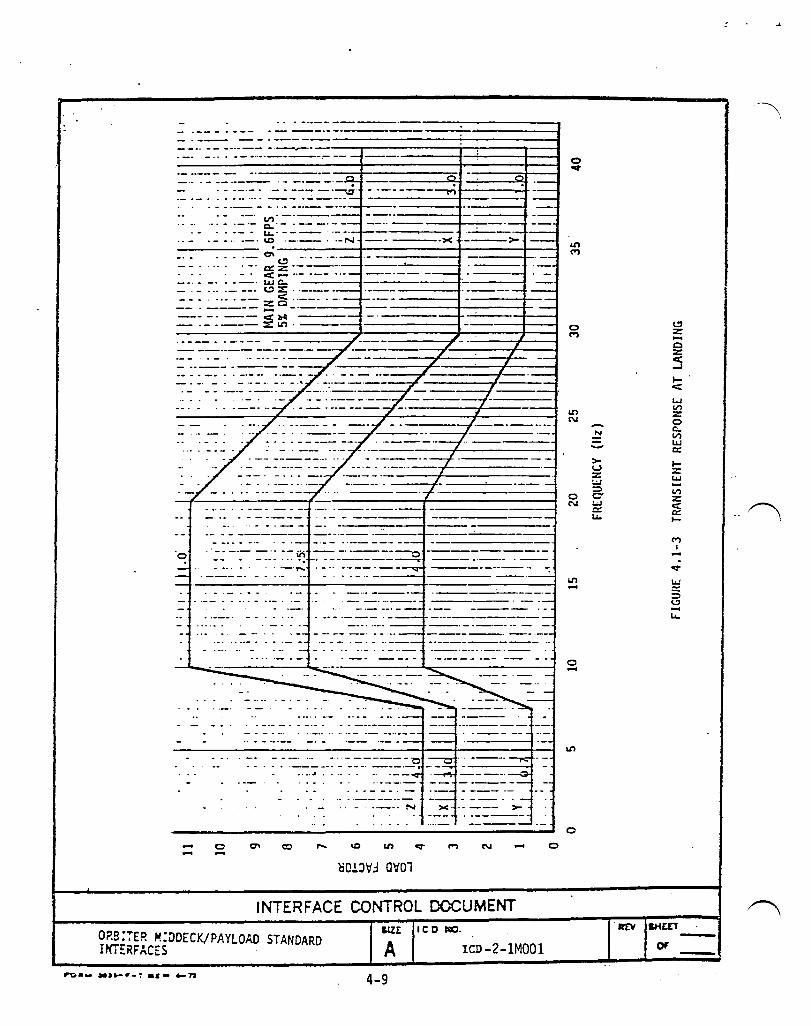
4.1 OPERATIONAL INERTIA LOADS. Operational inertia load factors given in Table 4.1-1 shall apply to payload elements located in the Kid-Deck. These load factors act in the directions of Orbiter axes Xo, Yo, and ZO as defined in Figure 3. 1. 1-1 and Figure 4.1-1 and shall be considered in all combinations for each fligh t condition. For transient flight conditions lift-off and landing, the load factors are presented as the elastic responses due to the first mode of the payload element on its mounting support in each of the three axes. The first mode natural frequencies of the payload element mounted in the Mid-Deck must be determined before using Figures 4.1-2 and 4.1-3 to find the transient responses for lift-off and landing, respectively. It should be noted that the steady-state load factors are -1.6 in Xo at lift-off and +1.0 in zo at landing.
The transient respons es at lift-off shall be comb ined with the appr~priate vibro-acoustic responses due to random vibration and ac~ustics environments defined in the subsequent paragraphs. The root-sum-square method may be used for combining the responses.
4-1
J
/~
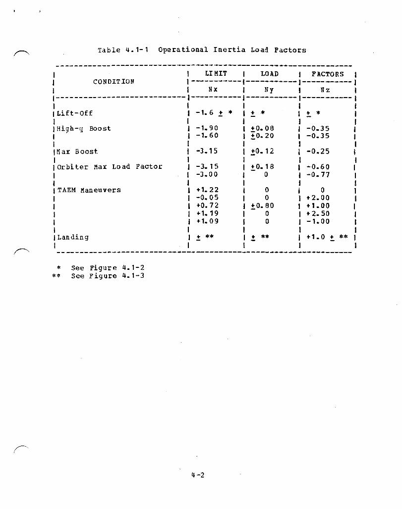
Table 4.1-1 Operational Inertia Load Factors
----------------------------------------------------------------I J LI KIT I LOAD j FACTORS I I CONDITION 1-----------1-----------1-----------1 I I Hz I Ny I Hz I 1---------------------------- -----------1-----------1-----------1 I I I I I Lift-Off -1.6.! * 1+* 1+* I I I J J J Hi~h-q Boost -1.90 I ±0.08 I -0.35 I
-1.60 I ±0.20 I -0.35 I
t1ax Boost
Orbiter Max Load Factor
TAEM Maneuvers
Landing
-3.15
-3.15 -3.00
I +1.22 I -0.05 I +0.72 I + 1. 19 I + 1.09 I I I
+ **
f I I ±0.12 I -0.25 I
!. O. 18 o
o o
!:,0.80 o o
+ **
I I I -0.60 I I -0.77 I I J I 0 I I +2.00 1 t +1.00 I I + 2.50 f I -1.00 I I I I +1.0 !. ** I I I
--------------------------~-------------------------------------
* See Figure 4.1-2 ** See Figure 4.1-3
4-2

4.2 E:1ERGENCY LAUDING LOAD FACTORS. Emergency landing load fact~cs specified in Table 4.2-1 shall apply to payload elements mounted in the Mid-Deck. They shall apply to components whose failure could result in injury to personnel or prevent egress from the vehicle. These load factors shall act independently ani the longitudinal load factor (Nx) shall be directed in all directions with 200 of the longituiinal axis.
Table 4.2-1 Emergency Landing Load Factors
1 ULTIMATE INERTIA LOAD FACrORS J 1--------------------------------1 I Nx I Ny J Hz I 1----------1----------1----------1 I I J 1 I +20.0 I +3.3 J +10.0 I 1 I I I I - 3.3 I -3.3 I -4. 4 I I I I I
4.3 RANDOM VIERATION. The random vibration environments applicable to components mounted in the Mid-Deck during launch and ascent shall be as follows:
20 - 150 Hz 150 - 1000 Hz
1000 - 2000 Hz
+6.00 dB/Octave o. 03 g~/Hz
-6.00 dB/O.::tave Composite = 6.5 g(rm~
En vironment exposure d ura,tion = 18.0 sec/flight in each of Xo, Yo, Zo axes. "
The exposure duration includes a fatigue scatter factor of 4.
Static equivalent limit load factors resulting from the random vibration input are:
± 12g ±12g ±12g
4.4 ACOUSTICS. Equipment to be mounted in the mid-deck shall be subjected to the acoustic spectra given in Table 4.4-1.
,.
4.5 KICK/PUSH-OFF LOADS. Payload-provided mid-deck equipment shall be designed for a limit 125 pound load distributed over a 4 in x 4 in area.
4.6 CENT ER-OF-GRAV Iry ALLOWANC E VERSUS WEIGHT.
4-3

~ I
4.6 •. 1 Pav12i!.Q._Att!!Q.h,ed 12-!.!ionics Ba,LWiretra12.
4.6.1.1 standard Lo::ker. For all Shuttle Orbiter Vehicles the CG of the payload element, package~ in a Standard Locker shall be not more than 14 inches from wiretray reference surface for all rows.
4.6.1.2 Payloads Attached to a Single Plate. Q'eight toCG relation for payloads attached to a single plate or- panel, is shown in Figure 4.6.2.1-1. Restrictions on CG location specifie:l in Paragraph 4.6.1.1 shall apply to payloads attached to single adapter plate(s).
4.6.1.3 Payload Attached to a Double Plate •. Restrictions on CG location, specified in Paragraph 4.6.1.1 shall apply to payloads attached to a double plate.
4-4
weight to CG relation for payloads attached to double adapter plate is shown in Figure 4.6.2.2-1.
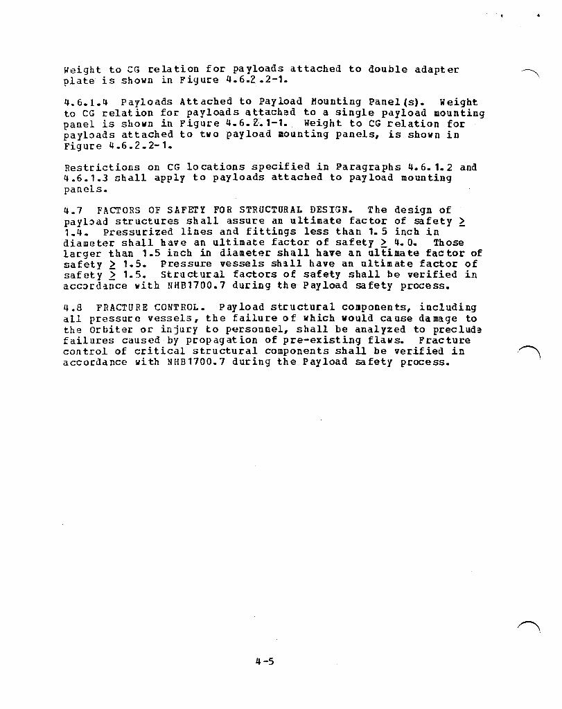
4.6.1..4 Payloads Attached to Payload Mounting Panel (s). Weight to CG relation for payloads attached to a single payload mounting panel is shown in Figure 4.6.Z.1-1. Weight to CG relation for payloads attached to two payload mounting panels, is shown in Figure 4.6.2.2-1.
Restrictions on CG locations specified in Paragraphs 4.6.1.2 and 4.6.1.3 shall apply to payloads attached to payload mounting panels.
4.7 FACTORS OF SAFETY FOR STRUCTURAL DESIGN. The design of payload structures shall assure an ultimate factor of safety ~ 1.4. Pressurized lines and fittings less than 1.5 inch in diameter shall have an ultimate factor of safety ~ 4. O. Those larger than 1.5 inch in diameter shall have an ultimate factor of safety ~ 1.5. Pressure vessels sh~ll have an ultimate factor of safety ~ 1.5. Structural factors of safety shall be verified in accordance with NHB1700.7 during the Payload safety process.
4.8 FRACTURE CONTROL. Payload structural components, including all pressure vesselS, the failure of which would cause damage to the orbiter or injury to personnel, shall be analyzed to preclude failures caused by propagation of pre-existing flaws. Fracture
· .
control of critical structural components shall be verified in /'" accordance with NHB1700.7 during the Payload safety process.
4-5
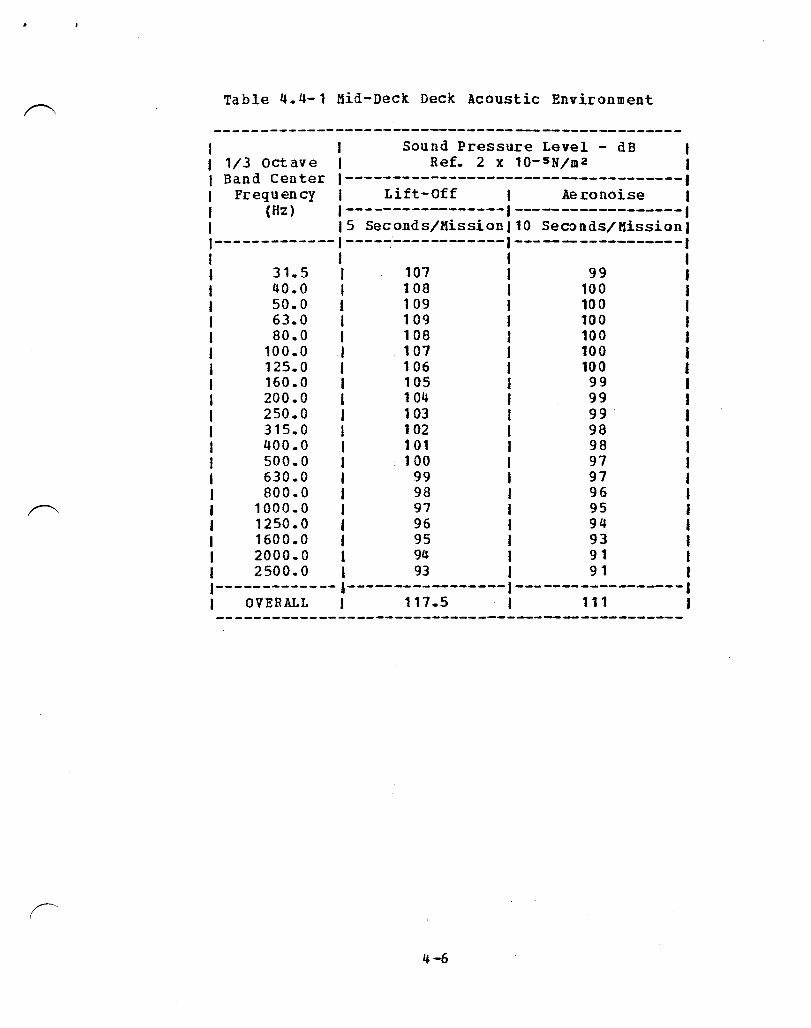
Table 4.4-1 Mid-Deck Deck Acoustic Environment
--------------------------------------------------Sound Pressure Level - dB
1/3 octave I Ref. 2 x 10-s N/m 2 I Band Center 1------------------------------------,
Frequency I Lift-Off I Aeronoise 1 (Hz) 1-----------------1------------------1 I 15 Seconds/Mission) 10 Seconds/Mission)
I-------------I----~------------I------------------I 1 J I 1 I 31.5 J 107 I 99 I I 40.0 1 108 I 100 I I 50.0 j 109 I 100 I I 63.0 I 109 I 100 I I 80.0 I 108 J 100 J I 100.0 I 107 I 100 I J 125.0 J 106 I 100 I I 160.0 I 1 05 J 99 I
200.0 J 104 I 99 I 250.0 J 103 J 99 I 315.0 J 102 I 98 I 400.0 I 101 I 98 I 500.0 1 .100 I 97 I 630.0 I 99 I 97 i 800.0 J 98 I 96 I
1000.0 J 97 I 95 I 1250.0 1 96 I 94 I 1600.0. 95 I 93 I 2000 • 0 I 94 1 9 1 I 2500.0 I 93 J 9 1 I
1-------------1-----------------1------------------1 I OVERALL I 111.5 I 111 I
4-6

".
LOAD FACTOR IS DEFINED AS THE TOTAL EXTERNALLY APPLIED FORCE DIVIDED BY THE CORRESPONDING TOTAL OR COMPONENT WEIGHT AND CARRIES THE SIGN OF THE EXTERNALLY APPLIED FORCE IN ACCORDANCE WITH THE ORBITER COORDINATE SYSTEM.
FIGURE 4.1-1 DIRECTIONS OF LOAD FACTORS
INTERFACE CONTROL DOCUMENT
ORBITER MIDDECK/PAYLOAD STANDARD INTERFACES
IoIZt leD 110.
~ ICD-2-1MOOl ro ............. " ..... .. 4-7
.~ •••••••••• ~~ •••••••• "_,' _ ••••• __ L ~ .... _ ••• _.~~_ •••••••••• _ ,-, •••••• -- •••

- -------------:---1 -- - ---'- --------f---f.---t ------.-------f
-- - -- c-· -. - -------t _.--._- Z .. -------- -_ ........ _------~-:: -::::.:. ~ ::2..:. :-=::- N
C • -- - - .. - - - -------. - - >< .------.~ _____ Ln ._._ .. __
-_._---------+ ---- .-------.---'--1'---+.---1 - -- -----------I-.--+----l
---'--.------~ .--I'--~
----_.;--
"'" __ --r- - ---
--11-----+-- .---.- ._----..
• __ >A
--..6 --_._-._ .
N . - >< .• >-
I"") N .... o
~Ol.:lV':l aV01
Ln I"")
o I"")
Ln N
0 N
Ln ....
o ....
o
-~ ->-w Z. LoJ ~ CT Lo.I c:: u..
INTERFACE CONTROL DOCUMENT
ORBITER HIDDECK/PAYLOAD STANDARD INTERFACES
r'O ... _'~r_" .,. A-ft
SIZE
A 4-8
leD NO.
ICD-2-1MOOI
at\' SHEET
OF
N I .....
... _ .. ------_._----------- --_.' ~::-::-:-:-:-:-:-:-:-=-::-::::::.::===========:j ._------.. -- --.--- ---"._.-.---"T""--------..;..-,.----....,.--....
---.. _--._ .. --~ ... ----"z:; . .... - .. -----,.,~---.--.~
- _.- - - ... -_.- _ .. _-+--Vl
._._-----_ .. -----+----~.- '---"'-1.1..._--- .. -----l.---I
Y:) • ·-N
0-~ a:: z .- ----.
<: - -- ._- ... wc... ----~~ .. _--_.
... -. -- zC3 .. --., -. ----- ..... -- -. --- <11-11 ------.-.---~Ll'l.----
----·x ---->-
._----1 ---~.-----
.. - - .. --- .. - - -----~
-.... o
::~:~:-: q; . -'1' ---.----... - .. ----01------
N >c.
Ll'l N .... oO.!.:lIt.:l Olt01
INTERFACE CONTROL OOCUMENT
O?S:iE? ~:~DECKIPAYLOAD STANDARD INTERFACES A
4-9
leD JCO.
leD -2-1MOOI
o
o M
Ll'l C\I
Ll'l ...
o ...
Ll'l
o
-~
~ z -c z <: ...J
l-e:: L..I II') Z 0 c... II') L'-l 0::
I-z: L'-l
II') z: c::: /~ c:: .. I-
M I ...
0::-
L'-l :::: ::l I.!' -1.1..

SINGlE PUTE TYPICAL
CENTER OF PLATE :.!:,3 INCH Y
UNIT
ZCM
t I
AVIONICS BAY WIRE TRA YS STRUCTURE REFERENCE
+3 INCH Z -UNIT CG (IN.)
X WflB~T eG(IN. )
Wlfhlrr X LBl CG(IN.)
X Wrl~ 14 MAX 51 14 MAX 37 14 .,AX 51
13
12
11
10
55 13 40 13
59 12 44 12
65 11 48 11
69 10 52 10
UNIT WEIGHT • WEIGHT OF PAYLOAD + WEIGHT OF SINGLE PLATE DATA SHOWN HERE IS FOR OPERATIONAL VEHICLES
CG LOCATION IN INCHES FROM WIRE TRAY STRUCTURE REFERENCE
55
59
65
69
FIGURE 4.6.2.1-1 MAXIMUM PAYLOAD WEIGHT AND CENTER OF GRAVITY FOR SINGLE-ADAPTER PLATE
INTERFACE CONTROL DOCUMENT SIlt ICD NO.
ORBITER MIDDECK/PAYLOAO INTERFACES A ICD·2-1M001
4-10

DOUBLE ADAPTER PLATE TYPICAl.
r I
YCM
AVIONICS BAY WIRE TRAY STRUCTURE REFERENCE
CENTER OF PLATE
CG(IH.)X UNIT WT (LB)
14 MAX 120 fl'AX
+3 INCH Y
CG(IN. )X UNIT WT (LB)
14 MAX B8
13 94
12 102
11 112
10 120 fl'AX
+3 INCH Z -CG(IN. )X UNIT wi
(!oS)
14 AAX 81
13 94
12 101
11 110
10 120 MAX
. . UNIT WEIGHT • WEIGHT OF PAYLOAD + WEIGHT OF DOUBLE ADAPTER
PlATE + WEIGHT OF 2 SINGLE ADAPTER PLATES DATA SHOWN HERE IS FOR OPERATIONAL VEHICLES
CG LOCATION IN INCHES FROM WIRE tRAy STRUCTURE REFERENCE
FIGURE 4.6.2.2-1 MAXIMUM PAYLOAD WEIGHT AND CENTER OF GRAVITY FOR DOUBLE ADAPTER PLATE '.
INTERFACE CONTROL DOCUMENT SIZE leo NO.
ORBITER MIOOECK/PAYLOAO INTERFACES A ICD·2-1MOOI
4-11
REV SHEfT
OF

r---. (
. ,r-.
5.0 THERMAL INTERFACE.
5.' ENVIRONMENTAL CONDITIONS. The envi~onmental conditions fo~ the mid-deck will vary as follows:
Dew Point
Cabin Pressure
C~bin Rate of Pressure Change
Namindl Qps
contingency
C~bin Oz Concentration
Temper:atur:e (Air)
Temperature (structure)
5.2 PAYLOAD ELE3ENT COOLING •
5-1
+61°P to +)9 0 F
14. 7 ..:!: O. 2 PSIA (Norlllal Operation)
8.0 ..:!: 0.2 PSIA (Abort Operations - Payload required to be powered off)
18.1 PSIA maximum (Ground Pressurization Test)
10.2 ..:!: 0.2 PSIA (EVA)
2.0 psi/mir. Rapressurization/DepressurizatioL
9.0 psi/min Depressurizationl Repressu~ization
25.9 percent at 14.7 ..:!: 0.2 PSIA 32.0 percent at S.O ! 0.2 PSIA 31.0 percent at 10.2 ! 0.2 PSIA
65-S00F (Normal Operations)
95°F Max. Peak (Ascent and Entry Transients)
TBDOP (Perry Flight)
1200 Max (All Mission Phases)
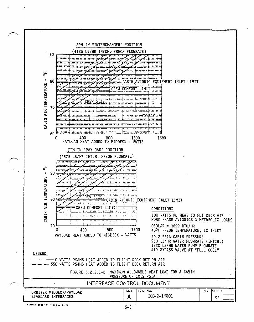
5.2.1 Pa§2ive cooli~~. Payload waste heat shall be considered dissipated to cabin air. This Section shall define the maximum total payload heat load that may be passively cooled with or without payload provided capability to internally circulate cabin air during on-orbit operations. Payloads which are required to operate during EVA or EVA prebreathe periods shall design cooling based on 10.0 psia cabin pressure.
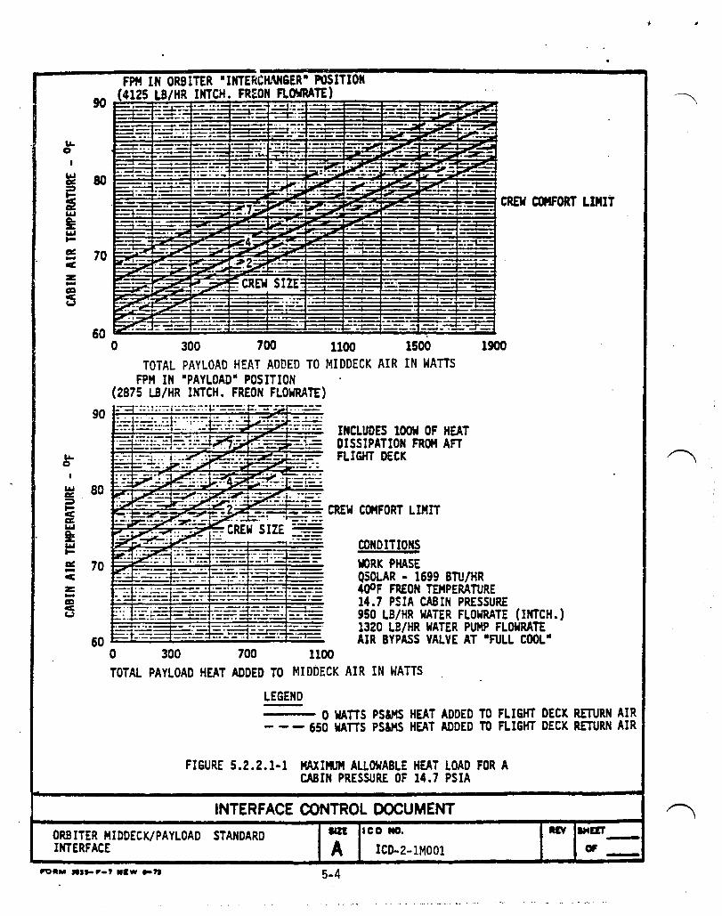
5.2.1.1 Maximum Allowable Heat Loads. Passively cooled mid-deck payloads shall dissipate heat to the cabin air to the extent defined in Figures 5.2.2.1-1 and -2. This maximum allowed shall be governed by several factors relating to the Orbiter and the particular mission flown. The total heat load consumed by any payload shall not exceed 200 watts average power (300 watts peak power for 30 minutes or less). It shall be the responsibility of the STS to manifest a complement of compatible payloads.
5.2.1.2 Passive Cooling Design Constraints. Payloads generating waste heat and not incorporating in the design a means of rejecting this heat to the cabin air by means of a fan or similar means shall be constrained to the following maximum continuous heat loads:
5-2

Standard Storage Locker Experiment Apparatus container
He~~ Load
60W 90W
Maximum air outlet temperature shall not exceed 120 0 P.
The allowable mid-deck heat load defined in Figure 5.2.2. 1-1, i~ the total that payload(s) will contribute to the cabin air. Payloads shall have the option of sharing the allowed heat load or staggering operations.
If a payload configuration requires multiple containers, then the design shall be based on a worse case thermal interaction between containers. This shall apply particularly to the internal component design.
5.3 EXTERNAL SURFACE TEMPERATURES. External surface temperatures of the payload elements accessible to the crew shall not exceed 113°F; inaccessible external surfaces shall not exceed 120 of.
5-3
LI. o
LI. C
60
'. ..-.. ·t'·· .. ------ -.
o 300 700 1100 1500 1900 TOTAL PAYLOAD HEAT ADDED TO MIDDECK AIR IN WATTS
FPH IN ·PAYLOAD" POSITION (2875 LB/HR INTCH. FREON FLOWRATE)
LEGEND
INCLUDES l00w OF HEAT DISSIPATION FROM AFT FLIGHT DECK
CONDITIONS WRK PHASE QSOLAR - 1699 BTU/HR 4()OF FREON TEMPERATURE 14.7 PSIA CABIN PRESSURE 950 LB/HR WATER FLOWRATE (INTCH.) 1320 LB/HR WATER PUMP FLOWRATE AIR BYPASS VALVE AT -FULL COOL-
--- 0 WATTS PS&HS HEAT ADDED TO FLIGHT DECK RETURN AIR - - - 650 WATTS PS&MS HEAT ADDED TO FLIGHT DECK RETURN AIR
FIGURE 5.2.2.1-1 MAXIMUM ALLOWABLE HEAT LOAD FOR A CABIN PRESSURE OF 14.7 PSIA
INTERFACE CONTROL DOCUMENT
ORBITER HIDDECK/PAYLOAD STANDARD INTERFACE
lIZ!
A ICD NO.
ICD .. 2-1MOOI .tv lHaT -fJI -
5-4
IJ.. C
~ ·~i~~~~f~-t=-=~~~:.t~~~~~1:~~::~~:~;':~::-: :;:~~.:. :~-~:~~ u 60 __ ~~:~~ ~~::~~!~i~;:~:i:~='::~:f:~~::···~:~<. t;_·~·~:.::~r·:~:::~
IJ.. C
I 90
o 400 800 1200 1600 PAYLOAD HEAT ADDED TO MIDDECK - WATTS
FPM IN "PAYLOAD" POSITION (2875 LB/HR INTCH. FREON FLO~KATE)
.... -........ . .. . I .- ••• . . ...
INLET LIMIT
CONDITIONS 100 WATTS PL HEAT TO FLT DECK AIR WORK PHASE AVIONICS & METABOLIC LOADS
70~----~~~~~~----~~ QSOLAR = 1699 BTU/HR o 400 800 1200 PAYLOAD HEAT ADDED TO MIDDECK - WATTS
LEGEND
400 F FREON TEMPERATURE, IC INLET 10.2 PSIA CABIN PRESSURE 950 LB/HR WATER FLOWRATE (INTCH.) 1320 LB/HR WATER PUMP FLOWRATE AIR BYPASS VALVE AT "FULL COOL"
------ C WATTS PStzMS HEAT ADDED TO FLIGHT DECK RETURN AIR -- -- --- 650 WATTS PStzMS HEAT ADDED TO FLIGHT DECK RETURN AIR
FIGURE 5.2.2.1-2 MAXIMUM ALLOWABLE HEAT LOAD FOR A CABIN PRESSU~E OF 10.2 PSIA
ORBITER MIDDECK/PAYLOAD STANDARD INTERFACES
INTERFACE CONTROL DOCUMENT SIZE leo NO.
A ICD-2.-H~OOl
5-5
REV SHEET
OF

6.0 ELECl'RICAL POWER INTERFACES.
6.1 ELEcrRICAL ENERGY.
6.1.1 Pay!Q.~.9 El~!~!i~~~3Y.-Allocation. The payload-e lelle n t electric energy allocation shall be as defined in its Payload Integration Plan.
6.2 DC POWER CHARACTERISTICS.
6.2.1 Power and VQ1~~g~-B~ti~.
6.2.1.1 Mid- Deck ceiling Location. DC electrical power providei by the Orbiter at the mid-deck ceiling location utility outlets (connector reference designators MO 13Q-Jl, M030F-J2 and M052J-J1) shall be as follows:
Pover ( 1) (Max Continuous at
Mis2.iQ!l Ph~2~ lol1~.9~ _~inimum_!oltage1-
M052J H013Q 11 030F 11IH !iQ~ HAX
(VDC) (VDC) (VDC) B US A BUS B BUS C
Prelaunch (Ser vici ng) 23 28 32 224v 215v 165w
Ascent 0 0 0 0 0 0
On-Orbit 23 28 32 224w 215w 165w
Entry 0 0 0 0 0 0
6-1

(1) Power specified is total available to be shared by mid-deck and flight deck utility outlets during simultaneous operation. Ea=h outlet is capable of providing this power level when outlets on the same circuit breaker are not in operation. rhe total power consumed by any pay load is limited to 200 wa tts average power for up to 8 hours (or 280 watts peak power for 10 seconds or less). No power will be available to payloads during ascent and/or descent mission phases.
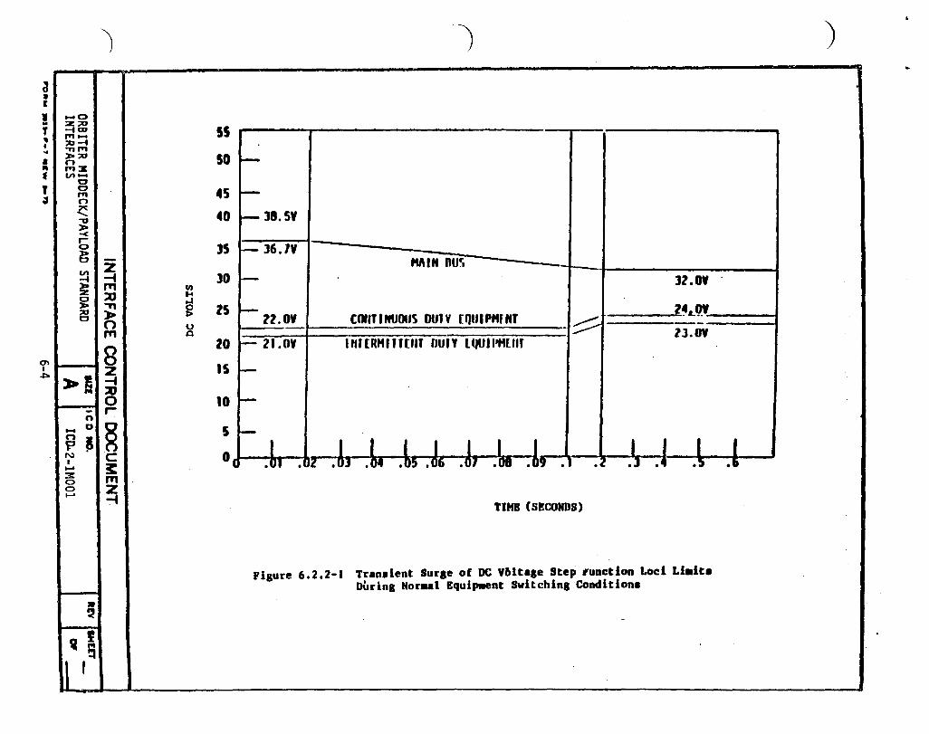
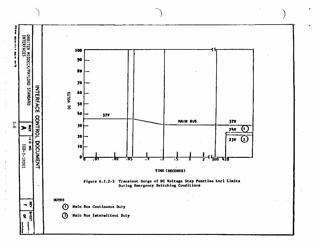
6.2.2 l~sient Sur~~1Qlt~~~Limits iSin~le ~!~n11. power transients shall be within the limits of Pigures 6.2.2-2 and 6.2.2-3 for normal, abnormal and emergency respect fully.
6.3 I NT ERFACE DES IGN.
Or biter 6. 2. 2- 1, conditions
6.3.1 OverlQ~Q-R£Ql~£11Qn. Orbiter circuit protection devices shall be as specified below.
6.3.1.1 Mid- Deck Ceiling' Outlets. Main 0: power sha 11 be supplied t3 mid-deck ceiling outlets at payload interface connectors M013Q-J 1, M030F-J2 and l'1052J-J1. Orbiter cire ui t protection for these connectors shall be provided by 10 amp circuit breakers, which also shall protect flight deck utility outlets. Each mid-deck utility outlet shall be capable of providing up to 7.0 amps when the associated flight deck utility outlets are not in operation.
6-2
6.3.2 lire §izin~. All payload element wiring connecting to Orbiter power sources shall be sizad to be consistent with associated circuit protection devi=es.
6.3.3 ~i2ment Return and GrOung!n3. Mid-Deck payload equipment electrical circuits shall have power returns isolated from each other and from equipment chassis, case, or enclosure by a minimum of 100 K OHMS.
6.3.4 ~I-Los2. Loss of Orbiter supplied power to the middeck payload element during on-orbit operation shall require manual reconfiguration of Orbiter power to restore power to the mid-deck payload elements. The power shall normally be restored withir. 15 minutes of the mid-deck payload element power loss detection.
6.3.5 gm~rgencI-Q2~~~tion~1~de2. For emergency operational modes, the payloads shall be able to sustain a safe condi tion with permanent loss of Orbiter pover.
6.3.6 ~load !le~~1_Act!!at!~~tiva1ioD-aB~Isolation. Each payload element sh all isolate its inpu t pover circui ts from all other payload elements.
6.3.6.1 Mid-Deck Ceiling outlets. Activation/Deactivation of payloads utilizing the mid-deck ceiling outlets shall be provided by switches located on mid-deck panels MOHQ, M030F and Ii052J. /~
6.3.7 IsolatiQR of~Q~~£~QY£S~2. The payload shall have provisions to assure the isolation of Orbiter power sources within the equipment such that no single failure, including short circuits, shall cause the power sources to be tied together electrically.
6.3.8 Ele£trical~~~~!nE. Electrical bonding provisions shall be accomplished in accordance with MIL-B-5087.
6-3
~ • r
• i ~ • .. • " • , ~
0\ I
.J'o
_0 :z ::0 -i OJ ,., ..... ::o-t " ,., »> ::0 n ,., ::Jt .." ......
C c ,., n ~ "'U »> -< r-0
~ en -t ~ C »> ::0 c
~I
-n _ 0
n A P. N I ...... 3: 0 0 ......
• ~ ~ ,
II r 9
')
55
SO
45 40
]5 -z -t ]0 ." C/)
::0 .... ..J
.." g lS l-0 u ." a
20
~ 15 -t ::0 0 10 r-
~ 5
C 0, ~ JTI Z -t
-) )
~
--1-38.5'
r- l6.1V MIN nu~- -
i- l2.0V
r- lZ.OV l~LQY CotITINU{)US DUlY £QIJIPMfN' -!;::::::: -lJ.OV
I- 21.0V IHHRMlff£l1T nun lQUII'HUIT
~
I-
~
I .~] .~4 .~5 .J, .J, .~8 .!, .1 I I I I
• 12 .UI . .l .4 .!t .ft
TIMB (SECONDS)
Figure 6.2.2-. Tran.lent Surae of DC 'bltale Step ,unction Loci Li.it8 DUring Nor .. l Equip.ent switching Condition •
-

.. 0 :I I
• -0 .. ~~ y .. rr1 ....
I ;0 ..... .. ." 1"'1
• >;0 ~ n ~ fI\ :J:
Vl ~ ..
T 0 0
~ 1"'1 n X '-"'0 > -< r 0 > 0 Z Vl -i ..... (T1 > :z ::tJ 0 -n » » :>0 0 0
(T1
0 0 2
~ I> ~I:ti 0 - r-
0
" ~ ~ H C n 3: t;I I (T1
N 2 I -i .....
3: 0 0 .....
,., ~
VI
~ ~
I I~
)
100 "-'0--'" c., I 90 -
80 f-
70 f-
60 f-til f-t ~ 50 0 -:> u Q
40 f-
-
JO 37.0V . J2V
f-
20 MAIN nus 24Y· c!) .
-10
2JY--C!)-f-
I I I I -«J I I o 0.001 .01 .02 .os • 1 .2 .5 z 5 7 .
TUIE (SECONDS)
Vlgure ~.2.2-2 Transient Surge of DC Voltage Step Function Loci Limits Durin~ Abnurmal'Switching Cunditions
HOTliS
o Continuous Vuty
(2) Intermiltent Duty
)
!
) .,
a • I
• .. T " , .. • .. I , tI
Cl I m
.... 0 :z: ;IIIJ -iOJ ,., --;IIIJ -t " ,., »>;IIIJ n ..... x en ......
CI CI ,., n ~ "0 ;):a -< .-0
l; en -t »> :z: 0 > ;IIIJ 0
~! ... -n 0 ....
a ~ I
N , ..... 3: 0 0 .....
'91! !i f
S
t- ~
)
-Z -4 ell P1 ... :0 g '"" ~ 0 g P1
8 ~ :0 0 r-
§ C ~ P1 z -t
NOTES
<D Q)
') ") .
•• 100 .. ,0 i-
10 - ,
70 I-
'0 -SO I-
'0 I- "f Milt IUS )2'
)0 f- (I) JII' 20 I-
I)' <V 10 fo-
I I I J I I 011 .UI .u": .U) • I 2-f'JDn~O .
TIME (SECONDS)
ri8ure 6.2.2-] Transient Sur8e of DC Voltale Step Function Loci Li.it. Durin8 Emer8ency Switchinl Conditions
Main Ius Continuous Out,
Main Ius i.ter.ittent Out,

7.0 INDUCED ENVIRONMENTS.
7.1 VIBRATION. (See Paragraph 4.3).
7.2 ACOUSTIC. (See Paragraph 4.41.
7.3 SHOCK. N/A.
7.4 LOAD FACTOR. (See Paragraphs 4.1,4.2).
7.~ TEMPERATURE. (See Paragraph 5.1).
7.6 ELECTROMAGNETIC COMPATIBI LITY (EriC).
7.6.1 Shu~tle=g£Qg~f~£-1Q~~£fe£~gs~_~nviro~l.
7.6. 1.1 DC Power Char act er ist ics.
7.6.1.1.1 Ripple and Transient Spike (Repetitive) Limits. Ripple and transient spike limits for electrical power provided by the orbiter at the indicated interfaces shall not exceed the voltage values specified in the following sub-paragraphs:
a. In-flight DC power bus ripple at the interface shall not exceed:
1. 0.9 volts peak-to-peak narrowband (30 Hz to 7 kHz) falling 10 dB per decade at 0.28 volts peak-to-peak at 70 kHZ, thereafter remaining co nstant to 400 MHz.
On orbit, during the Orbiter hydraulic circulation pump start up (300 milliseconds) 1
sawtooth ripple voltage of 4 volts peak-topeak amplitude will appear ~n the 28 volt DC power bus at a frequency of 500 to 700 Hz.
2. The momentary coincidence of 2 or more signals at anyone frequency shall not exceed the envelope defined as 1. 6 volts peak-to-peak (30 Hz to 7 kHz) , falling 10 dB per decade to 0.5 volts peak-to-paak at 70 kHz, thereafter remaining const3.nt to 400 MHz.
b. In flight DC Pover Transients S~ikes (Repetitive).
1. In flight DC power transient spikes (measured common mode) shall not exceed the impulse eguivalent of 300 X 10- 6 volt seconds above or below normal line voltage. Peak transient spikes shall be limited to :50 volts from nominal bus voltage on the positive line, and !30 volts from nominal on the negative line.
7-1

Rise and fall rates shall not exceed 56 volts/microsecond.
c. Grounj DC Power.
1. The narrowband ripple voltage at the interface shall not exceed an envelope with limits 1.2 volts peak-to-peak (30 Hz to 7 kHz), falling loy-linear to 0.28 vol ts peak-to -peak at 70 kHz, thereafter remaining constant to 400 MHz.
2. The momentary coincidence of two or more signals at anyone frequency shall not exceed an envelope with limits 2. 0 volts peak-to-peak (30 lIz to 7 kHz" falling log-linear to 0.5 volts peak-to-p~ak at 70 kHz, thereafter remaining constant to 400 liHz.
3. Transient spikes (measured common mode) shall not exceed the impulse equivalent of 300 X 10- 6 volt seconls above or below normal line voltage. Peak transient spikes shall be limited to ~50 volts from nominal bus voltage on the positive line, and ~30 volts from nominal on the neyative line. Rise and fall rates shall not exceed 56 volts/microsecond.
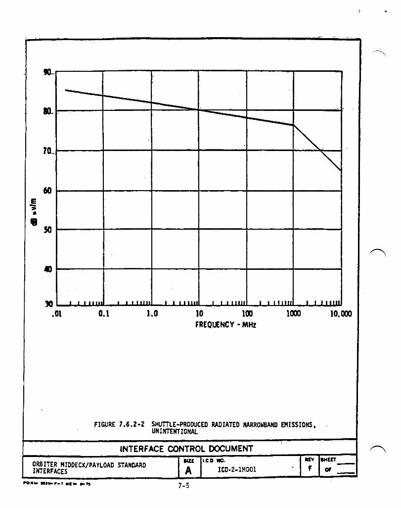
7.6.2 RaQii!1~Q-1!!t~£i~f&!!.f.f. The Shuttle prod ucedradia ted fields environment shall be limited as follows:
a. AC magnetic fields shall be limited to less than 1)0 dB above 1 picot esla (30 Hz to 2 kHz), falling 40 dB per decade to 50 kHz.
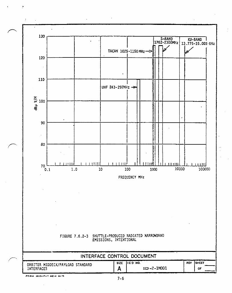
b. Electric fields are defined in Figures 7.6.2-1 and 7.6.2-2 for unintentional emissions, and Figure 7.6.2-3 for intentional emissions.
Electric fields are listed below for intentional emissions from the Wireless Crew :ommunication units (WCCU). Duple x voice communications shall be provide} by bulkhead/panel mounted spacecraft terminal units and remote body-worn units in each system. As many as 5 systems could be in use depending on number of crew. There shall be 10 VHF carriers available.
No.
1 2 3 4 5
Carrier Freq. in MHz
169.500 174. 100 171.925 180.300 170.325
7-2
Electric Field in dB mic ro Vim
114 114 114 114 114

6 7 8 9
10
174.300 171.025 180.100 171.825 186.200
114 114 114 114 114
1'hese levels shall be considered when evalua ting the possibility of operating radio frequency receiving equipment or electronic field sensing equipment.
c. Lightning produced magnetic fields shall be limited to a peak level of 10 amperes/meter with a rise to peak value in 2 microseconds and fall to zero in 100 ~icroseconds. The payload shall be designed so that a failure due to a lightning strike shall not propagate to the Space Shuttle.
d. The design o.f the Or biter shall prec:lllde any electrostatic discharges.
7-3

1:1)
120 ~
'" , 110 "
\ dB"Vlm{MHz 1m
\ 90 1\
\ '.
~ 80
'" ~ 70 I I I 11111 I I I 11111 I I I I lilt I I 111111 I I I "'111
.01 .1 1 10 1m um 10, em MHz
FIGURE 7.6.2-1 SHUTTlE-PRODUCED RADIATED BROADBAND EMISSIONS. UNINTENTIONAL
INTERFACE CONTROL DOCUMENT REV SHEET -F or
IIZE leD Il1O.
A ICD:-.2-1MOOl ORBITER MIDDECK/PAYLOAD STANDARD INTERFACES .
7-4
e -:. • .-
-.. . .. - ..
-- -10... .. -
-~. 70_
~ 60
50
., lO I I I 11111 • I t 11111 I I I 11111 I I I I 1111 I I I r J IIJ j J I 11111
.01 0.1 1.0 10 100 um 10.000 FREQUENCY - MHz
FIGURE 7.6.2-2 SHUTTLE-PRODUCED RADIATED NARROWBAND EMISSIONS, UNINTENTIONAL
INTERFACE CONTROL DOCUMENT
ORBITER MIDOECK/PAYLOAO STANDARD INTERFACES
IIU
A ICD MO.
ICD·2-1MOOl .., SHUT -F or -
7-5
~
.~
l~r-------.-------,--------r-------.~~~~------~ S-BAND KU-BAND J
1762-2300MHz 13.775-15.003 GHz 1"'""1/ I /
TACAN l025-1150MHz-> IP' ~
120r-------t-------~-------r1---------~~~---+~----~
110r-----------r---------~------------~1----1I-----J~~~---~~--------~
UHF 243-297MHz ~
~100r------------r----------~------------~1-----H~--~~------~~------~
90r-------------;--------------r------------~----_H~----~~--------4_+_--------~
80r-----------+-------------+-------------+1----~----_+~+_----_+~--------~
I 70~~I-~II~II~lIwl----~II~I~I~lIwll~~I~~II~ Il!lllli ____ ~tLL~llullilll~'UI~LI~IUII~I1D_l~~II~IUI~ILWIIII
0.1 1. 0 10 100 1000 10000 100000
FREQUENCY MHz
FIGURE 7.6.2-3 SHUTTLE-PRODUCED ?~DIATED KARRa-3AND EMISS IONS. INTENT!ONAL
INTERFACE CONTROL DOCUMENT
ORBIiER MIDDECK/PAYLOAD STANDARD INTERFACES
SIZE Ie D NO.
A ICD·-2-1MOOl
7-6
REV SHEET
OF ----

1.6.3.1 Payload Element Produced Conducted Noise. The Payload generated conducted emission limits, applicable to all DC power interfaces, shall be as follows:
a. DC Powec
1. The power line conducted emissions shall be limited to the levels indicated in Figure 7.6.3.1-1.
2. The payload generated transient spikes produced on DC power lines by switching or othec operations shall not exceed the limits defined in Figure 7.6.3.1-2 for normal operation and Figuce 7.6.3.1-) for abnormal opecation. Rise and fall rates shall not exceed 56 volts/microsecon~
7.6.3.2 Paylaad Produced Radiated Fields. The payload produced radiated fi elds sh all be limit ed as follows:
a. The generat ed AC magnetic fields (applies a t a dista nce ot 1 me te I" from an y payload equipment) shall not exceed 130 jB above 1 picotesla (30 Hz to 2 kHz) falling 40 dB per decade to 50 kHz.
b. The radiated electri~ fields shall not exceed the levels defined in Figures 7.6.3.2-1 and 1.6.3.2-2.
c. Electrostatic dischacges shall not occur within the Orbiter other than those isolated from the gaseous environment (nitrogen-oxygen mixtuce) and shielded by the payload to satisfy the requirements of the sutpa cag ra ph s "a II and It b" above.
7-7

. 1 .•
: . , .j . . . .. , , . . : . 130 ---... -----________________ it----...i-----_--
N·: :.:.~ ::~ • I • . ~ • • • '! ..a..
120 ----------------------------~.--.-.. -----.--~.~.~'--~----~~ .i'·~ ... :,
110 . -"'--' ..... - .-.----_ ... -_._-- ... -.--~--: .~- i'\::: 100------------------------~------------------~--------
t ___________ :.~:-~-.. . . Ii. ...:
. . . .. ~ :: .
80 ------------------------------------------------~---"' . __ ._.! . :
• i
10 FREQUENCY. Hz
FIGURE 7.6.3.1~1 PAYLOAD ALLOWABLE CONDUCTED NARROWBAND EMISSIONS {SHEET 1 OF 2}
INTERFACE CONTROL DOCUMENT
ORBITER MIDDECK/PAYLOAD STANDARD INTERFACES
IIU leo MO.
A ICD· 2-1MOOl
7-8

- --- --:._, ... _-+-_ .. _-' .. --:
- I . ~ ..• L .• -. ~ ... - -" . - --+. _ . !' I
I -- ~.-- --~- -~ •
t _ •. - - .... ! .... - .... _. _1. --+---.! -- ----.. -1 i I I . :
~I =====+=j ==~~-::-1==========: "!a i·
- ... !_._; .. _-
----- ---_. --- . !
; .
:u:» N = ---- =:: .. ==~-..:==~-=:::::::==:;====- CI. .. - .... ~ .. --- --.'--- ---+------+---;.....--- ~.
;...;. ::::---. ..,..----,----i-' -----------..:-__ -,:-~,--:::::::~.--------.:------:- ~ .... _
r- i = .. - ...... - ... ..,.. -~j--.~~ =T~-==.~:-
: : 1 : .. _ .. :: - ... T---·_·· ....
&t't
.. _._- --_-_ ~.::_ ===::..:-.~: .. ::-::~:.:.:-. sa
CI N
INTERFACE CONTROL DOCUMENT
ORBITER MIDDECK/PAYLOAD STANDARD INTERFACES
IIZE ICD NO.
A ICD-2-1MOOl
7-9
-N
1!5 N
i '" -i -'" '" -is
I a: • = ~ u a ! U ...,
I -' ~
= 9 ~
f ....
I .... · M · u:» · I"-..., a: . a -....
ItlV SHEET
01
!~

t_ ...
. , 1 -;
I I I ! : ! t---·-- -·-··4
I !. ~--~r_;------r-._.-_-_,rl-_-"'~_1r.-_-_.-.-._--~4-.-=~~;.-----~.
t - --' -. -~ ---..... ; _L
i .-J.-.-.~
: . . . --. .-. -- --- i , .
j._._._ •• '1' J ... ~_. __ ~ ____ ._ I 1·: i .----":'_.....;.:--""""':".---+;-tl-~--~--~I_ !-.-.--.-~ - .- 1--' -. ~- -1 •. _._ • __ ..•. __ tl . - _~.I.. _. _. ____ ~ ,. I
I . ---~----------••. --.-; I I ,.. : ~
I I j I • j L , ;...-----~----- .. ----t---iJ--~-----~--~---
. --------.----------~~~~----~--~~--+---------~.--~~.---• . .. - i --.-~ .--... i - -- -r-------- ----.- --- ·--------....:~r-----:.--~--~
.!. .--: i···-- .--.~: . "-1'---_._ .. _- T- - .
. '. -... - .. -.- . - --.. -...... - . - . __ ... _ .... , " -- ._--------
- __ e. - - - _. ___ .-- _. ~."'~ -
;-_.- -_ .. _---------- -_.- - : "----- '- ._------ -_. ---_._- '-~ ..... - .... --.~ .... - .--------.----.. - .. -.----.--~-----~ ;..-- --.....,.i--------·-~·-------t-------: --·---~------I
.,_. __ .- . .---~-----
~ ~--: ::--::-----._-.-.-.. -. _.- -:. ~::- .. -: .... _.'P' ........ -.
---- --,---_·_-_ .. --- ......... 1--r
. _'--
::----
.. _.;... . . I .. ; . '- I .... -'--.~---' -- -'---- .. _--;.--:--
! ._- -.. - .. .. .- ..
--~---.---;.-.--.--~-.. -.. -~----.-.---.. J _. ~
r-- --.• _._-- -_ ...... __ .. - .. -.------.-- .. ----.--~:. -_. -._.-.. - -.. _. - .... --_. -. ---- .. -- ... ~-- - ._-- --- ._-• - ._- .-. - .... ~ ••• _- _. '!' - .. ~ •••• ,
.- -t-.... ---- ... _--: .- ----.-~------.....::...:.-~ .. :.:.~.:.~=: ~.:..~:...-..: .. -
--~------_._-----_ .. - -'-'-'--'-- .
--_ .... __ .. _- ----.- .. --- .. -----
8 -
:so -
-.
N I -· fI') · '" · ..... ~ ~ -&A.
. 0
'" CI W1
CI .. o fI')
o - 00
39YJ.1OA ~
INTERFACE CONTROL DOCUMENT
ORBITER MIDDECK/PAYLOAO STANDARD INTERFACES
ailE leD teO.
A ICD- 2-1MOOl
7-10
REV SHUT --

CD .., =.:..t .. .,. - I I I I
-~ ==f'" I ~--------- -----~----~~------~;~---------T----~----~----~----~----+----~I----~----~-+~------~----------+-----------~--~-----! i !! ='-~ --. 'I - .~. - '-r' , .1"---- . ~ .... ··t-·· .. · .. ··--··4 --.. ~- .. ~
1- . ... . :.-------.---.. -.-!r-.-t'-.--..... ~;-' ..•• - -1- ---; _ .. ·_-t--- ..... ~ ..... - ~ .... - -- ....... : -----: :! i; .. i - '··1 - .. --. '--i- .-+---+-.- - : .... - -1-······~·· ...... ~ .. - ~ -.. -;
. . . ... .. - ... - - .. -: ... - --i
.!
t . . . I . -.-- ---:--"-7----;'-·- "j-' '------'1-:--: .... :--!
i .; I';"S ~====~====~+=~~====~~==~I!'=====i -~------- -~ ----.. ---4-tf--------...;.-----..,..-.---..--------""""'l'----.....,..---'
~ . .-j .- "-" -y._ .. :- .. -- ~ _ ... -_._- ~ -.- .... - -_ ... -..
-----~--- i -----! .... L ~ t-- - .. - -- .-... --! - - --.--- 7 .••• -.....
-=~~--~~.~ .. ~ ' .. ~ j .---.~: . .... : - -.: ... -~ . -.. -.. -.. ~ i
-- ---- ... -. . ----.------ ...... =========='::-====..:==_ c_ ~ .... -_. ----_ .. __ ._. _... -- ...... ----. --- --.-------~-.-.---'-.--..... en -- -_.-
: .. _._- _.,--- --~---.-. ----_._--------._----_.---- - . - --_.--------.. ---- -------------'---------._-------
.-~ - -.-~.---.. -.-.-. -'--'---.-.-.- ~.~:----.. -.-.-~-.-.--.--.:---.-.. ---.. -.-. ..;..~.-.---- '::'- - ... -~-.-.-.. --~.---. I --7 - .... 1;-· ----. ----
'"T ----- •• - •• "'-:- --- _ ... - .... - ........ ~ •• _._.- --, .............. .
__ ._ - - __ ~ _______ . I ~ ..... ~_:.~ _ ..
-. - . -.. -T---~------------:-:_'__:_:__:__:_--------------.. -.. --
-- . --_.- - .... --- -.-.
- .. -~ .- .--: .. -...; ... --- -- ---. . . --- --_._--- ----- --_ .....
e .. ~
39'1.1.101. ~
e N
INTERFACE CONTROL DOCUMENT
ORBITER MIDDECK/PAYLOAD STANDARD INTERFACES
IIZE leD teO.
~ ICD·2-1MOOl
7-11
e -~ -. c
REV IHEET
Of
I ! c .. I
I ~ R C en ~ -&. VI
Ii w -VI Z
~ caz
!~ .... ~ ~ :2w c..
CC C§% ....w >-t-<en c..>-~en
c~ ~~ ca: .... t-wu >w z .... ww
I"'t I -· I"'t · .., · ....
w a: e -~

! I i I I j ! I I/": :: II jill i ! ! ; I : , . ,"",-, : I ' ! i : I! I I ' \1 I I i I! i I I ; ; ! :
Ilillll!! I:I! illl !il! il'illjlliif~I!11 !IIIII II~IIII i I ~ ,e:eoo~~~~:~" ~, ~IO
I I I : i I •• j ~!"- i
., , 'I I I il,1 !i: ii:iiill!!'! I
.-; I • 7, I
; I;' ,;, I ,! I! J i!! ; Ii, iii ;:!{I ! '::!!I~·' i
llilllll!l:j"i '::! 'j l,j·:iJ'l:,lIill:IIL/'1'I'III' , ' :
,~
!!1!1111!I!!ill!'l !!:j:!il!lll;lll!iill~jll!!l!i!'1 ;:i 0
i""
~ I I I r
I ' : J I ! : i '.If.' I '.' : I I : I I
! I : i i, ' I : , : 1, : i j Ii: >"\ I ; t! i , I' 'I' I . , : I' , , I , I ' • .' ""': : t I'. ,I I I • • t
I ~ii:' :',', "j :I\!' ~I ,:!IJli!liil,r"'II!i'II',',';lilll roo ! ~ I; '1.; It: ! I! ! ; : I : :,;. ~ I I' I! I I ! I t Ii! :! i I !
~~~~~~~ ... -,
I ~ I
: ~ : '~ : " I! , :: I ,~ .,! I I :; 'I: , ,: 1
, , ",/; I ". I iit!I'" 1 1 '1,,1" ,
I 'i :,11/ li"'I' f ! I ,! I , : ; : I II ! I I : I ! II , III! I I ! I j·i I ii' I i
~t \ i:! I \! i \ G I: II ! \ i!!'! j I! I; II \ 1111 \; 11111 11111 11111 I! 1111! ~ c -- - e
(;) -
INTERFACE CONTROL DOCUMENT
~
N
s:
ORBITER MIDDECK/PAYLOAD STANDARD ISTERFACES
SIZE leo NO.
A ICD-2-1M001
REV SHEET
OF
!rOA'" "!"'-F-1 HEW '-73 7-12
til Z 0 .... til \,1 ... ~ t:.l
0 Z <: :::l 0 <: :::> c:: :::l
0 ::J E-o <: .... 0
~ ~ i5 <: .,.. S :2 0 <: 0 ~ >< 2: · ..... ,
N · ...., · '" · r--
2 G .... t:..

80 - '. -
'- --70 - - -~ .. - - -I- -_.
..... - _. -- -~ - '-I - .•. - . - ~. - -- -_. - - !- --. - -,- ... -- - -. ,--<
60 'I ----. -- --
2: .. I' - f--I'
> 1# ::::I ~.-
m I·· . -50
l-
i) iI' ~,
.1-.
I'
.... !- - . - l- .- .. - ~ - - . ... - .+. -- - -. . . -_. .•. . -I-- - -. - ~r' - - -40 -- + I'
. - -- - - -'-- - - .. -.0;: --'- .- .
- . - ~ 10- .- _ .. -, .-- --.. - - - t.~ - -- .... ' - .. --- - _. -- - - - ,- .. r- - - - . -~ ~ - --- -30 ....-- -- "". - -i 1--- . - - -. _. ... . .. -_. .-. I--- - . -- - .. - ,- -- I--. - ~. .. -- . --- - - -, ::; ... -~, .. - . - - ~ -.. 1-' - ... - - . _.- ._ . .. . -. -- - --- - - -r-' - - ... -- - . .. _. .- . . - - - _e· .•.. _. - ----
0.01 0.1 1.0 10 100 1000 1000C FREQUENCY (MHz)
FIGU~ 7.6.3.2-2 PAYLOAD ALLOWABLE RADIATED NARROWBAND EMISSIONS
INTERFACE CONTROL DOCUMENT
ORBITER MIDDECK/PAYLOAD STANDARD IIZl ICD MO. REY 84EET -
INTERFACES A ICD·2-Hl001 til -7-13
7.6.4.1 Payload Element Power Returns. Circuit returns and isolation 3f circuit returns shall De maintained.
7.6.4.2 Electrical Bonding. The Orbiter-to-Payload electrical co un t ing inter face s hall be electri cally bonded to provide homogeneous electrical characteristics. All electrical and mechanical elements shall be securely bonded to structure in compliance with MIL-8-5087. The payload bonding surfaces shall match the alodined surfaces shown Oll the assembly drawings for thf: payload mounting panels and adapter plates. All aluminum surfaces used for bonding shall be originally cleaned to bare metal and then chemical filmed per MIL-C-S541, Class 3 (gold aladine 1200LN936A, or equivalent).
A cleaned and alodined test point shall be provided and identified on the payload.
7.6.4.2.1 Electr ical Bon ding of Eg uipment. Equi pment containing electrical circuits which may generate radio fre~uencies or circuits which are susceptible to radio frequency, shall be so installed that there will be a continuous, low-impedance pa th fro~ the eguipment enclosure to structure. The metallic shells of all electrical connectors shall be electrically bonded to the equipment case or the bulkhead mount with a DC resistance of less than 2.5 milliohms. The DC resistance between the mated halves of the connectors shall not exceed 50 milliohms.
Wire harness shields external to equipment, requiring grounding at the equipment, shall have provisions for grounding the shields to the equipment through the harness connector backshell, or for carrying single point grounded shields through the connector pins.
All equipment electrical bonds and their respective interfaces sha 11 comply wi th ?iIL-B-S087.
7.6.4.2.2 Electrical Sonding of Structures. ~ll electrical bond interfaces shall be in accordance with Paragraph 7.6.4.2.
7.6.4.2.3 Payload Surface Electrostatic Charging. All rayload haLilware elements shall comply with the Class-S bond requirements of MIL-B-5087. All payload harciware elements shall be designed to prevent the accumulation of an electrostatic charge on their surfaces. The specific usage and method employed shall be negotiated with STS.
7-14
7.b.4.?t~ Circuit Peference symbols. The circuit refer-ence Hy~bDl~ for use on tho SpacE Shuttle progr-am shall be as illustr-atcd and defined as follows:
structure reference - a connectiou to vehicle structure.
Primary pow\c~r reference - a connection to the vehicle p r i ill ar y DC lJ 0 w or l' et urn.
7.6.4.1 Power Circuit Isolation and Grounding.
7.(1.4.3.1 G['ound Support Equipment Isolation and Grounding. GSE i.nterf"l.cirq with payloads shall be isolated from payload circuits by d winimurn ot 1 megohm, except where balanced differential circuits are used. In the case of balanced differential ciccuit3, each side of the cir-cuit shall he balanced to ground by no less than 4000 ohms. Coax cables, with their inherent 1rounding :Jf the signal return to structure, are permitted, providing their interface with other payload or systems doos not pr.-opag,lte that ground t.o circuits which are already referenced to Jr.-ouod at some ether point.
7.7 r~YLOAD ELEMENT CLEANLINESS. The external surfaces of the Payload Element shall be cleaned prior to its installation into tr.d Orbi te r l'tid- deck. Clean 1 iness shall conform with a v isih ly clean level as specified in SN-C-OD05.
7.8 MATERIALS AND PROCESSES. Materials and processes used in design and fabrication of the Payload Element and associated support equipment shall comply with SE-R-0006 and NHB-8060 and shall be verifiecl in accordance with NHB1700.7 during the payload safety process.
7.9 PAYLOAD EFFLUENTS. The Payload shall provide for safe GJnt'linmcnt of any by-product of payload experiment-gaseous, liluid or solid. No toxic or any other gases shall be discharge:! ill to the mid-deck env ironment.
7.10 ILLUMINATION. Any special illumination shall be provided by th e Payload.
7.11 NUCLEAR RADIATION. Materials used in any payload subsystpm, containing natural or man made radioisotopes (in any quantity, including trace amount~ shall be avoided without prior approval by waiver obtained from NASA-JSC. The waiver request shall specify the ral ioisotope spe:: ies, q uan tit ies or act iv ities, and other pertinent data such as the exact location within the mid-decK area liher e the mat er ial is to be ins ta lIed.
7-15

THIS PAGE INTENTIONALL Y LEFT BLA NK
7-16

8.0 ELECTRICAL WIRING INTERFACE.
8.1 GENERAL.
8.1.1 Identification_2£_lnterface.
8.1.1.1 Mid-Deck Panels and Connectors.
a. Ceiling Area
-----------------------------------------------------------1 CONNECTOR 1 PLUG/SOCKET RECEPTICLE 1 J DESIG 1 CABLE I PAYLOADS 1 TYPE!
1-------1-----------1----------------1---------------1------1 1 MODQ I Pl I NB6GE14-12SNT2 1 NBOE14-12PNT2 1 DC j
1-------1-----------1----------------1---------------1------, 1 MO)OF 1 P2 1 NB6GE14-12SNT2 I NBOE14-12PNT2 1 DC f 1-------1-----------1----------------1---------------1------1 1 11052J 1 Pl 1 NB6GE14-12SNT2 I NBOE14-12PNT2 I DC J
8.1.2 A££roved Connectors for Mid-Deck_R~ylogQ Element-Y§~. All mid-deck payload element electrical connectors and connector contacts that interface with the Orbiter shall satisfy the requirements specified in the following NASA applicable specifications:
401138277
40 M39569
8.1.3 Connector Dead Face. At the time of connector rna te or dema te, no current shall be flowing across the interface.
8.2 CABLE SCHEMATICS.
8-1
8.2.1 l1.id-Qeck Panel !1Q112.L.11030l.L~2J.\ DC electrical power cable interfaces are shown, in Pigure 8.2.1-1.
8-2

,~ (
UTILITY OUllETS I HARNESS <
I PAYLOAD
I 0 I I
r--L \0
t:. ~ () T o· r--M ..: - f
..: '0 NO crn~ I :;;: ':.) _I
Q ..., ., ~
:> .HO ~ =.::1
:>ClASZ !zJ :%) Z N =.:: =.:: < . . " NI~ ::.. '-=~ ~Yl ~"- I
J " I 1 :;~1" <
0 ...... ::h.
u - I N := NO crn~ I
:> :%) c- ., , N .BO 0----0 'K :>ClASZ I
..., ::r:: =.::
W I =.:: I , Nl"li io-- y, '-
c-... -0 :;;:
:.:J :z ;:
I I
I 1 ~ll < t.:)
M \0 .., ~~ --..: - f'
~o IX ml~
'J :> -: .., ~ .BO ~
1 '/., :lQASZ
~J :.:: =.:: ~ ,I "-' Nl"lI I '-- ~ '-N .. .., ::;:
.. ' z < ::..
INTERFACE CONTROL DOCUMENT
I SIZE ICO NO.
ORBITER ~IDJ~CK/PAYLOAD S7A:;:).:.R:) !~!ERF ACES A ICD-2-1MOOI
8-3
!-t <
:t:I 11)% !-t:;) z-:zJ;-:;;:< z:.; C:;) -..: :t:I 11):,:) <% -':..:)...J :l ... . -.. ' =::3
-I N
" :%)
'." ;: ~ -t:.
I
REV SHw_l OF .
NASA-JSC

End of Document