Standard hydrogen electrode and potential of zero charge ... · Standard hydrogen electrode and...
12
General rights Copyright and moral rights for the publications made accessible in the public portal are retained by the authors and/or other copyright owners and it is a condition of accessing publications that users recognise and abide by the legal requirements associated with these rights. Users may download and print one copy of any publication from the public portal for the purpose of private study or research. You may not further distribute the material or use it for any profit-making activity or commercial gain You may freely distribute the URL identifying the publication in the public portal If you believe that this document breaches copyright please contact us providing details, and we will remove access to the work immediately and investigate your claim. Downloaded from orbit.dtu.dk on: May 01, 2020 Standard hydrogen electrode and potential of zero charge in density functional calculations Tripkovic, Vladimir; Björketun, Mårten; Skúlason, Egill; Rossmeisl, Jan Published in: Physical Review B Condensed Matter Link to article, DOI: 10.1103/PhysRevB.84.115452 Publication date: 2011 Document Version Publisher's PDF, also known as Version of record Link back to DTU Orbit Citation (APA): Tripkovic, V., Björketun, M., Skúlason, E., & Rossmeisl, J. (2011). Standard hydrogen electrode and potential of zero charge in density functional calculations. Physical Review B Condensed Matter, 84(11), 115452. https://doi.org/10.1103/PhysRevB.84.115452
Transcript of Standard hydrogen electrode and potential of zero charge ... · Standard hydrogen electrode and...

General rights Copyright and moral rights for the publications made accessible in the public portal are retained by the authors and/or other copyright owners and it is a condition of accessing publications that users recognise and abide by the legal requirements associated with these rights.
Users may download and print one copy of any publication from the public portal for the purpose of private study or research.
You may not further distribute the material or use it for any profit-making activity or commercial gain
You may freely distribute the URL identifying the publication in the public portal If you believe that this document breaches copyright please contact us providing details, and we will remove access to the work immediately and investigate your claim.
Downloaded from orbit.dtu.dk on: May 01, 2020
Standard hydrogen electrode and potential of zero charge in density functionalcalculations
Tripkovic, Vladimir; Björketun, Mårten; Skúlason, Egill; Rossmeisl, Jan
Published in:Physical Review B Condensed Matter
Link to article, DOI:10.1103/PhysRevB.84.115452
Publication date:2011
Document VersionPublisher's PDF, also known as Version of record
Link back to DTU Orbit
Citation (APA):Tripkovic, V., Björketun, M., Skúlason, E., & Rossmeisl, J. (2011). Standard hydrogen electrode and potential ofzero charge in density functional calculations. Physical Review B Condensed Matter, 84(11), 115452.https://doi.org/10.1103/PhysRevB.84.115452
PHYSICAL REVIEW B 84, 115452 (2011)
Standard hydrogen electrode and potential of zero charge in density functional calculations
Vladimir Tripkovic,1 Marten E. Bjorketun,1 Egill Skulason,2 and Jan Rossmeisl1,*
1Center for Atomic-scale Materials Design, Department of Physics, Technical University of Denmark, DK-2800 Lyngby, Denmark2Science Institute, VR-III, University of Iceland, IS-107 Reykjavik, Iceland
(Received 25 May 2011; published 26 September 2011)
Methods to explicitly account for half-cell electrode potentials have recently appeared within the frameworkof density functional theory. The potential of the electrode relative to the standard hydrogen electrode is typicallydetermined by subtracting the experimental value of the absolute standard hydrogen electrode potential (ASHEP)from the calculated work function. Although conceptually correct, this procedure introduces two sources oferrors: (i) the experimental estimate of the ASHEP varies from 4.28 to 4.85 V and, as has been previouslyshown and is reconfirmed here, (ii) the calculated work function strongly depends on the structure of the waterfilm covering the metal surface. In this paper, we first identify the most accurate experimental reference for theASHEP by revisiting up-to-date literature, and validate the choice of electron reference level in single-electrodedensity functional setups. By analyzing a dozen different water structures, built up from water hexamers, intheir uncharged [potential of zero charge (PZC)] states on Pt(111), we then determine three different criteria (nonet dipole, no charge transfer, and high water flexibility) that a water structure should possess in order for itscomputed ASHEP to closely match the experimental benchmark. We capture and quantify these three effectsby calculating trends in the ASHEP and PZC on eight close-packed transition metals, considering the four mostsimple and representative water models. Finally, it is also demonstrated how the work function changes withexchange-correlation functional.
DOI: 10.1103/PhysRevB.84.115452 PACS number(s): 68.08.−p, 73.30.+y, 71.15.Nc, 71.15.Mb
I. INTRODUCTION
In electrochemistry, all half-cell electrode potentials aregiven relative to a chosen reference electrode of some well-known reaction, for example, the standard calomel or thestandard hydrogen electrode (SHE). In many electrochemistryexperiments, taking the difference between two electrodepotentials alleviates the problem of determining the potentialon an absolute scale. Nevertheless, the absolute potential scaleis still of great importance when comparing electrochemicaland ultrahigh vacuum (UHV) experiments and when tryingto match semiconductor and solution energy levels1 in, forinstance, photoelectrochemical devices.
Density functional theory (DFT) based methods for mod-eling electrochemical systems and, in particular, for treatingcharge-transfer reactions at the electrochemical interface havejust started to appear.2–12 In these simulations, the electro-chemical cell is customarily split into two half-cells andthe redox reactions taking place at the two electrodes arestudied separately. Here, the absolute potential enters as a keyparameter because it is no longer possible to measure potentialdifferences between the two electrodes. We would, however,like to distinguish between three different categories of theo-retical electrochemistry studies. In the first category, we findinvestigations of the thermodynamics of electrochemical reac-tions and calculations of redox potentials.13,14 In these studies,the potential does not have to be taken explicitly into account inthe DFT simulation, but can rather be added a posteriori. Thesecond category comprises the energetics of charge-transferreactions. To study these types of problems, it is necessary toexplicitly include the potential in the DFT model. At the sametime, it is possible to introduce an internal potential reference,which means the accuracy of the absolute potential is of lessimportance.15,16 Finally, in the third category, we find problemslike the matching of semiconductor and solution energy
levels that demand highly accurate estimates of the absolutepotential.
In general, the DFT based methods use the work function(WF) of the water-covered metal electrode as a measureof the absolute electrode potential. In order to obtain arelative potential scale, the WF scale needs to be coupledto a normal thermoelectrochemical scale, for instance, of theSHE. This matter can be approached in two conceptuallydifferent ways. The most straightforward and most common isto use an experimental value of the absolute standard hydrogenelectrode potential (ASHEP), i.e., the experimental WF thatcorresponds to SHE conditions, as reference. However, thereis a large uncertainty in the ASHEP reported in the litera-ture; they vary from 4.28 to 4.85 V.17–26 Many properties,including energy barriers and, hence, rates of charge-transferreactions, are strongly potential dependent, which rendersthe use of the most correct experimental estimate essential.Moreover, since the calculated WF depends strongly on thestructure of the water at the metal-aqueous interface,27,28
employing an experimental reference is a sound approachonly as long as the real system is faithfully mimicked inthe simulations. It should be noted, though, that it is usuallydifficult to capture properties of bulk water in these typesof first-principles simulations as computational constraintslimit the number of water molecules that can be explicitlytreated.6,29 Alternatively, one can use a theoretical value ofthe ASHEP, internal to the system and perhaps different fordifferent metal-water-vacuum setups. This approach has theadvantage that it requires a less realistic representation ofthe simulated metal-water interface, but in turn a scheme fordetermining the theoretical ASHEP is needed. We have re-cently devised such a scheme15 and, subsequently, successfullyimplemented it to model the hydrogen evolution and oxidationreactions.16
115452-11098-0121/2011/84(11)/115452(11) ©2011 American Physical Society
VLADIMIR TRIPKOVIC et al. PHYSICAL REVIEW B 84, 115452 (2011)
Although, as we have already discussed, many problemscan be solved using an internal “low-quality” ASHEP ref-erence, there are cases such as the previously mentionedmatching of energy levels when a good theoretical estimateof the ASHEP is vital. Therefore, in this paper, we present anextensive investigation of the theoretical ASHEP. Particularattention is given to how the choice of water model, used toemulate the interfacial water, affects the calculated ASHEPand makes it deviate from the experimental counterpart. Mucheffort is also put into evaluating the somehow related quantitypotential of zero charge (PZC). By thoroughly examiningthe available literature, we first determine the most reliableexperimental benchmark value for the ASHEP. Invokingthe fundamental concepts of the absolute potential scale,developed by Trasatti and others,1,30–35 we then pinpointthe most appropriate choice for the reference level of thecomputed WF. Subsequently, by briefly revisiting our earlierworks, we show how an internal ASHEP reference can bereadily established.15,16 Next, we perform a comprehensiveinvestigation of Pt(111)-water systems. We demonstrate howthe WF, which corresponds to the PZC when the water filmcontains no ions, varies with the structure of the interfacialwater and identify the different contributions to the WF.Guided partly by this study, we identify three properties thatthe model water film must possess in order to reproduce theexperimental ASHEP. We then evaluate the ASHEP for a setof representative electrode-water systems and quantify thedeviations from the experimental value owing to the use ofunrealistic water structures.
II. EXPERIMENTAL ESTIMATES OF THE ASHEP
Experimental values of the ASHEP reported in the earlierliterature resided mostly on measurements of changes inthe WF upon water adsorption. The WF was measured bymeans of immersed electrode setups,20–22 UHV studies,36,37
or, similarly, through measurements of the potential differenceacross the Hg|air|H+|Pt,H2 cell in the absence of any specificadsorption or charge transfer (so-called streaming Hg jetmethod).17,18 There is a large scatter in reported valuesobtained using these techniques (4.44 to 4.85 V). The discrep-ancies have been attributed to, among other factors, surfacecontamination, the orientation of water in UHV experimentsbeing different from the one in bulk water, and to partial chargetransfer.30,32 Here, it is worth noting that the lower value hasbeen identified as the most reliable one by Trasatti and alsothe value recommended by the International Union of Pureand Applied Chemistry (IUPAC).1
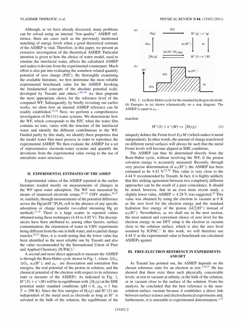
A second and more direct approach to measure the ASHEPis through the Born-Haber cycle shown in Fig. 1, where �Gd,�GI, αS(H+), and μe− are dissociation and ionization freeenergies, the real potential of the proton in solution, and thechemical potential of the electron with respect to its referencestate (a measure of the ASHEP). As indicated in Fig. 1,H+(S) + e−(M) will be in equilibrium with 1
2 H2(g) at the SHEpotential under standard conditions (pH = 0, pH2 = 1 bar,T = 298 K). Since the free energies of H2(g) and H+(S) areindependent of the metal used as electrode as long as H+ issolvated in the bulk of the solution, the equilibrium of the
FIG. 1. (a) Born-Haber cycle for the standard hydrogen electrode.(b) Energies in (a) shown schematically on a step diagram. TheASHEP is equal to μe− .
reaction
H+(S) + e−(M) ↔ 12 H2(g) (1)
uniquely defines the Fermi level EF(M) (which makes it metalindependent). In other words, the amount of charge transferredon different metal surfaces will always be such that the metalFermi levels will become aligned at SHE conditions.
The ASHEP can thus be determined directly from theBorn-Haber cycle, without involving the WF, if the protonsolvation energy is accurately measured. Recently, throughvery precise determination of αS(H+), the ASHEP has beenestimated to be 4.42 V.25,38 This value is very close to the4.44 V recommended by Trasatti. In fact, it is highly unlikelythat this striking agreement between two completely differentapproaches can be the result of a pure coincidence. It shouldbe noted, however, that in an even more recent study, aslightly lower value, ASHEP = 4.28 V, was suggested.26 Thisvalue was obtained by using the electron in vacuum at 0 Kas the zero level for the electron energy and the standardhydration free energy of the proton �G0
S(H+) instead ofαS(H+). Nevertheless, as we shall see in the next section,the most natural and convenient choice of zero level for theelectron energy in our DFT setup is the electron in vacuumclose to the solution surface, which is also the zero levelassumed by IUPAC.1 In this work, we will therefore use4.44 V as the experimental value to benchmark our calculatedASHEPs against.
III. FREE-ELECTRON REFERENCE IN EXPERIMENTSAND DFT
As Trasatti has pointed out, the ASHEP depends on thechosen reference state for an electron at rest.1,30,33 He hasshowed that there exist three such physically conceivablelevels: at rest in vacuum at infinity, in the bulk of the solution,or in vacuum close to the surface of the solution. From hisanalysis, he concluded that the best reference is the near-solution-surface vacuum because it establishes a direct linkbetween surface science and electrochemical experiments and,furthermore, it is amenable to experimental determination.1,33
115452-2

STANDARD HYDROGEN ELECTRODE AND POTENTIAL OF . . . PHYSICAL REVIEW B 84, 115452 (2011)
FIG. 2. (Color online) (a) Schematics of an electrochemical cellshowing a set of work functions {�k
i } measuring the work needed tobring an electron from the Fermi level of the metal to four differentfree-electron reference states. �∞
i , �Si , �i , and �′
i denote infinitevacuum, bulk solution, near vacuum, and near-solution-surfacevacuum WFs. (b) DFT model of an electrochemical cell comprisedof Pt(111) and Pd(111) electrodes immersed in a common ion-freeaqueous solution, vacuum cleaved half-way between the electrodes.The z axis equals the unit-cell size in the surface normal direction. Thefigure illustrates the convergence of the electrostatic potential withrespect to the number of water layers. The water layers are mirrorimaged on the two electrodes.
As we shall see in the following, it is also the most naturalreference in DFT calculations.
A typical electrochemical cell is illustrated in Fig. 2(a).Appropriate half-cells are obtained when the electrochemicalcell is vacuum cleaved at a point in the solution where theelectrostatic potential (EP) is no longer affected by the metalsurface. Four WFs required to bring an electron from the Fermilevel of the metal Mi to a chosen reference state are indicated,where labels �∞
i , �Si , �i , and �′
i stand for far (or infinite)vacuum, bulk solution, near vacuum, and near-solution-surfacevacuum WFs. Three of them, �∞
i , �Si , and �′
i , are potentiallyrelevant for determination of the ASHEP.
In conventional periodic DFT calculations, �∞i is not
defined because of infinite surfaces imposed by periodicboundary conditions. As a consequence of the infinite ex-tension of the surface, even a point in vacuum infinitely farfrom the surface will feel the presence of the surface dipoles.The second plausible reference is the point in bulk solution.Obtaining a solution reference point is straightforward giventhat enough water is included in the cell. This, however,reflects on the system size, and the computational cost needed
to perform such a relaxation is staggering. Additionally, aportion of the water must be fixed because any wiggling ofthe water molecules can shift the reference level.6 In contrast,the near-solution-surface vacuum level can be readily obtainedby the WF in metal-water-vacuum setups and, moreover, themeasurement does not entail any confinements. Hence, it is themost natural free-electron reference state in DFT calculations,and �′
i is thus the most suitable WF.The DFT counterpart to an electrochemical cell is shown
in Fig. 2(b). In ordinary DFT simulations of such setups, theFermi levels of the two electrodes (M1 and M2) will always bealigned irrespective of the absolute potential and the electrodematerial. Once the Fermi levels of M1 and M2 are aligned,�′
1 and �′2 should also become equal (since alignment of
the Fermi levels means that the electrodes have assumedthe same potential), given that the solution phase is thickand polarizable enough to screen the fields from the metals.However, this is usually not the case in DFT calculationsdue to the limited amount of water that one can afford toinclude in the simulations. Convergence of the EP profilefor a Pt(111)|water|vacuum|water|Pd(111) cell with respectto the number of water layers is displayed in Fig. 2(b). Agradual improvement of the near-solution-surface referencepoint with increasing thickness of the water is clearly observed.The mid-vacuum EP discontinuity (obtained by electrostaticdecoupling of periodically repeated supercells) is fairly largein the cell containing only a single water layer. However,it becomes much smaller after addition of a second layerand it essentially vanishes when a third water layer hasbeen added. In Sec. V, we will demonstrate how inadequatewater structures introduce, sometimes substantial, errors inthe calculated ASHEP and PZC. It turns out that efficientscreening is one of the keys to accurately predicting theseproperties.
IV. ESTABLISHING A THEORETICAL, INTERNALREFERENCE FOR THE ASHEP
In this section, we describe how an internal reference for theASHEP can be established in a DFT based electrochemistrystudy. The methodology is summarized here because of itsrelevance for the following study. For more details about theprocedure, we refer to our previous works.15,16
We start with an atomic setup consisting of a metal slab andan electrolyte represented by water layers outside the surface[cf. Fig. 2(b)]. The metal-electrolyte interface is charged byadding hydrogen atoms to the first water layer outside themetal surface. These hydrogen atoms spontaneously separateinto protons that become solvated in the water bilayer andelectrons that are transferred to the surface of the metal slab.The charge separation, in turn, creates an EP drop across theinterface. The surface charge, and hence the potential, can bevaried in steps by changing the concentration of protons in thewater layer.
A link between the thermoelectrochemical scale of the SHEand the WF �′ can be established by focusing on the freeenergy of the solid-liquid interface as it is charged with protonsand electrons. The total or integral free energy per surfacemetal atom (or surface area) relative to H2 for a system with n
115452-3

VLADIMIR TRIPKOVIC et al. PHYSICAL REVIEW B 84, 115452 (2011)
protons and N surface atoms is given by
Gint =(G(N,n) − G(N,0) − n
2μH2
)/N, (2)
where μH2 is the reference chemical potential of hydrogen.Gint corresponds to the free energy stored in the interface setup by the protons in the water layer and their counter chargein the metal. Gint will be quadratic in potential if the interfacebehaves as a perfect capacitor. The derivative of Gint withrespect to the proton concentration is the chemical potential ofprotons and electrons
dGint
d(n/N )= μ(H++e−) − 1
2μH2 . (3)
The role of the μH2 term is to define the reference. Hence, ifwe choose μH2 to equal the free energy of H2(g) at standardconditions, the WF corresponding to the minimum of Gint willdefine the potential of the SHE (reaction (1) is in equilibrium)on an absolute scale.
V. RESULTS AND DISCUSSION
In the following, we first (Sec. V A) calculate the PZCof Pt(111) using a large number of different water mod-els and both Perdew-Burke-Ernzerhof (PBE) and revisedPerdew-Burke-Ernzerhof (RPBE) exchange-correlation (XC)functionals (for computational details, see Appendix A). Wedefine the PZC as the WF �′
Pt(111) of the metal covered withan ion-free (i.e., in our case unprotonated) water film.1,31 Thecalculated PZC is found to depend strongly on the structureof the water film, and the choice of XC functional turns out tobe of importance too. We disclose the physical origin of thelarge scatter in calculated values and discuss its consequences.Subsequently (Sec. V B), the ASHEP and PZC are computedon the most close-packed surfaces of eight transition metalsM = {Ru, Pd, Pt, Au, Ag, Re, Rh, Ir}, using four qualitativelydifferent water structures. These results are then used to discernmetal- (or WF-) dependent trends in the PZC and to illustratethe importance of a set of physical properties of the water filmfor accurate estimation of the ASHEP. Finally, in Sec. V C,we comment briefly on the use and applicability of external(universal) and internal ASHEP references.
Before presenting the PZC and ASHEP results, we willbriefly introduce the water models used in this study (morespecific details are given in the subsequent sections). The waterfilms are formed from bilayers of different net dipole orien-tations, stacked in a layer-by-layer fashion. From UHV andDFT studies, it has been inferred that, on many close-packedtransition-metal surfaces such as Pt(111),39–44 Ru(0001),44–46
Pd(111),44,47 and Rh(111),44,48 the low-temperature structureconsists of water molecules adsorbed in the form of hexagonalrings, which give rise to the well-known honeycomb pattern.Furthermore, it has been shown that the diversity of thehexagon-based structures is rich. For example, the layerforming on Ru(0001) is half dissociated45 and triangulardepressions are found in the layer forming on Pt(111).49 Thehexagonally structured water layer has been named bilayerstructure because it consists of two differently oriented watermolecules, located at slightly different distances from thesurface; one is lying flat with the molecular dipole plane
nearly parallel to the surface, and the other one has a danglinghydrogen bond directed either away or toward the surface. Todistinguish between these two orientations, we will henceforthrefer to them as H-up and H-down structures. We note thatthese structures have previously been successfully employedin modeling of hydrogen oxidation-evolution and oxygenreduction reactions.16,50
Although there is still little experimental evidence asto whether these structures will be preserved at ambientconditions, a recent molecular dynamics study showed thata mixture of H-up and H-down structures is likely to exist atT = 300 K on Pt(111) and Ru(0001).27 Albeit in the samestudy, the authors found that, on some other close-packedtransition-metal surfaces (Au, Ag, and Pd), water moleculesacquire random orientations and the hexagonal pattern be-comes disrupted. These metals will also be investigated in thiswork, but since our aim is to systematically study how the PZCand ASHEP vary with water model rather than to identify themost stable water structure under a certain set of environmentalconditions, the uncertainty about the actual structure will notaffect our conclusions.
A. Sensitivity of the PZC to water structure and XC functional
In this section, we carry out a detailed analysis of the PZC ofPt(111) covered with thin water films. The PZC is evaluated forwater films of single- and double-bilayer thickness for almostall conceivable combinations of H-up, H-down, and H-mixed(a neutral layer containing an equal number of moleculardipoles pointing up and down) bilayers. Additionally, welook at thicker films, containing up to five H-mixed layers.Some PZC data for the other seven transition metals will bepresented in Sec. V B. The results for Pt(111) are summarizedin Table I. The systems are grouped according to the nominalnet dipole moment (DWL = xd) of the adsorbed water film (weuse the convention that x > 0 for net dipoles pointing awayfrom the metal surface, x < 0 for net dipoles pointing towardthe surface, and x = 0 for neutral films). Schematics of thefilms are shown in the first column of the table, with arrowsindicating the dipole moments of individual water layers.Two arrows pointing in the same direction indicate a finitedipole moment, whereas oppositely aligned arrows indicate anominally neutral water layer that is expected to have no netdipole.
According to DFT calculations with the RPBE (PBE) XCfunctional, the WF �Pt(111) of pristine Pt(111) is 5.60 (5.74) eV.As a comparison, the experimental value for Pt(111) currentlygiven in Ref. 51 is 5.93 eV. Upon adsorption of a waterfilm, the metal WF changes by �� = �′
Pt(111) − �Pt(111). Themagnitude and sign of �� depend on the structure of the waterfilm and the distance between the metal surface and the firstwater bilayer. As shown by Materzanini et al. and by Jinnouchiand Anderson, �� can, to a good approximation, be dividedinto two distinct contributions.11,52 The first, ��orient, stemsfrom the orientation of the water molecules and is obtainedby calculating the dipole moment of the water film, isolatedand frozen in the geometry it adopts at the metal surface. Thesecond contribution, the polarization part ��polar, is causedby charge redistribution at the metal-water interface uponadsorption of the water film. Most of the charge transfer is
115452-4

STANDARD HYDROGEN ELECTRODE AND POTENTIAL OF . . . PHYSICAL REVIEW B 84, 115452 (2011)
TABLE I. Work function �′Pt(111) of Pt(111) in different Pt-water-vacuum setups. Upon adsorption of water on pristine Pt(111), the work
function changes with �� = �′Pt(111) − �Pt(111). �� is conveniently separated into two contributions: (i) ��orient, given by the static dipole of
the isolated water film, corresponding to an expected nominal dipole moment DWL = xd; and (ii) ��polar, a polarization contribution, arisingdue to charge transfer between the water film and the metal surface when they are brought in close contact. ��polar is strongly dependent onthe distance dPt-O between the Pt surface and the O closest to the metal surface in the first water layer.
Pt-water �′Pt(111) �� ��orient ��polar dPt-O
model DWL (eV) (eV) (eV) (eV) (A)
2d 4.01a/4.12b −1.59a/−1.62b −1.49a/−1.35b −0.11ad/−0.26bd 3.77a/3.49b
2d 3.58a/2.91b −2.02a/−2.83b −2.08a/−2.06b +0.08ad/−0.76bc 3.62a/2.72b
0d 5.31a/4.43b −0.29a/−1.31b −0.12a/−0.34b −0.16ad/−0.96bc 3.94a/2.33b
0d 5.52a/5.41b −0.08a/−0.33b −0.02a/−0.25b −0.04ad/−0.08bd 4.33a/4.17b
0d 5.43a/4.98b −0.17a/−0.76b −0.05a/−0.29b −0.11ad/−0.47bc 3.74a/3.18b
0d 5.55a/4.54b −0.05a/−1.20b −0.01a/−0.22b −0.05ad/−0.97bc 3.90a/2.39b
0d 5.46a/4.65b −0.14a/−1.09b −0.05a/−0.15b −0.08ad/−0.94bc 3.83a/2.44b
0d 5.55a/5.78b −0.05a/+0.04b −0.01a/0.05b −0.06ad/−0.05bd 3.88a/4.01b
0d 5.44a/5.64b −0.16a/−0.10b −0.03a/−0.04b −0.12ad/−0.07bd 3.72a/3.97b
−2d 6.54a/6.71b +0.94a/+0.97b +2.07a/+2.36b −1.12ac/−1.40bc 4.09a/4.08b
−2d 6.73a/5.96b +1.13a/+0.22b +1.25a/+0.98b −0.06ad/−0.77bc 4.10a/3.12b
−4d 7.42a/7.63b +1.82a/+1.89b +4.24a/+4.65b −2.41ac/−2.77bc 4.06a/3.80b
−6d 7.69a/7.67b +2.09a/+1.93b +5.78a/+5.83b −3.69ac/−3.90bc 3.83a/3.91b
−8d 7.79a/7.82b +2.19a/+2.08b +5.61a/+5.75b −3.44ac/−3.69bc 3.83a/3.86b
aRPBE exchange-correlation functional.bPBE exchange-correlation functional.cConsiderable charge transfer between the Pt surface and the water film.dSmall charge transfer between the Pt surface and the water film.
localized at the interface (cf. Fig. 3), but a smaller long-rangeelectron polarization effect that can extend far out in thickwater films can also be discerned.53 The polarization part isgiven by
��polar = −edpolar
Aε0, (4)
where A is the surface area of the slab supercell and the netdipole moment due to charge redistribution dpolar is obtainedby performing an integration
dpolar =∫
S
∫ z1
z0
dx dy dz �ρ(x,y,z)z (5)
over the electronic charge density change upon adsorption�ρ(x,y,z). The integration
∫S
stretches over the surface areaA of the slab and the integration
∫ z1
z0starts at the midpoint
between two layers in the slab and ends at the center of thevacuum. As seen in Table I, the two contributions (��orient +��polar) add up to almost exactly ��.
When taking a closer look at Table I, we first notice thatthe net dipole moment of the water film is of paramountimportance for the magnitude of the WF. As a rule of thumb,a net dipole moment pointing away from the surface lowers�′
Pt(111), whereas the opposite effect is observed for a net dipolemoment pointing toward the surface. This result is what youwould intuitively expect to see and is fully consistent withearlier findings.27 We also see that when the net dipole startsbuilding up in one direction, that is, when the dipoles of theindividual water molecules become more and more oriented inone direction, �′
Pt(111) will gradually approach the saturation
limit. This effect is clearly demonstrated also in Fig. 2(b) whereup to three H-down bilayers have been stacked upon each other.Further inspection of Table I reveals that the magnitude of��polar is strongly correlated with the distance dPt-O betweenthe Pt surface and the O closest to the metal surface in thefirst water layer, especially for systems with moderate chargeredistribution (|��polar| � 1). Moreover, the RPBE and PBEfunctionals often give substantially different �′
Pt(111). Thisdifference can also be traced back to variations in ��polar. PBEusually predicts a smaller metal-water separation, resultingin a larger charge redistribution. If, on the other hand, theelectronic structure is calculated for a fixed nuclear geometry,the two functionals yield very similar �′
Pt(111).It is worth noticing that, even when performing calculations
at the PBE level, we generally overestimate the metal-waterseparation for H-down (3.12 A) and H-up (3.49 A) structurescompared to corresponding theoretical values found in theliterature. Other authors typically report dPt-Os of approx-imately 2.7 A for these structures.11,27,43,44,49 As a result,compared to others, we underestimate the charge transfer and,thus, get a less negative ��polar and a larger �′
Pt(111). Mostexperimental values reported for the PZC of Pt are of theorder 0.4 V versus SHE,31,54–56 which would correspond to a�′
Pt(111) of about 4.8 eV and a water-induced WF change ofapproximately −1 eV. Obviously, among our systems, only afew of the neutral water films, treated at the PBE level, matchthese experimental values. We note, however, as pointed outbefore,6 that a really rigorous treatment of the PZC wouldrequire statistical averaging, either over a complete set of staticlow-temperature water models, weighted by their total energy
115452-5

VLADIMIR TRIPKOVIC et al. PHYSICAL REVIEW B 84, 115452 (2011)
FIG. 3. (Color online) Optimized structures of two [(a), (b)] and four [(c), (d)] H-mixed water bilayers adsorbed on Pt(111). The calculationswere performed with the PBE [(a), (c)] and RPBE [(b), (d)] XC functionals. The solid black lines indicate laterally averaged redistribution ofelectronic charge upon adsorption of the water films.
(stability), or of a long room-temperature molecular dynamicssimulation.
To gain further insight into the difference between the twoXC functionals and the relationship between the metal-waterseparation and the WF, we analyze the stacks of H-mixedbilayers more carefully. Special attention is paid to howthe geometry and the WF change as the thickness of thewater film is increased. Figure 3 shows the 0-K structures ofPt(111) with water films consisting of two and four H-mixedlayers, optimized with PBE and RPBE, respectively. For thethinner film, PBE predicts a much smaller Pt-water distance(dPt-O = 2.39 A) than RPBE (dPt-O = 3.90 A). The smallerseparation results in a much larger charge transfer (cf. Table Iand Fig. 3) and, hence, a much larger contribution from ��polar
to �′Pt(111). For this particular system, PBE predicts a 1-eV
smaller �′Pt(111) than RPBE, mainly due to the charge-transfer
effect. When more water layers are added, little happens to theequilibrium distance in the RPBE simulation (dPt-O = 3.88 Afor the four-layer-thick film) and, hence, �′
Pt(111) remainsfairly constant. However, with PBE, the separation suddenlyincreases to dPt-O = 4.01 A as the fourth layer is added.Accordingly, the amount of charge transferred is now similarto that predicted by RPBE (cf. Fig. 3) and �′
Pt(111) = 5.78 eValso agrees well with the �′
Pt(111) = 5.55 eV given by RPBE. Asimilar trend is observed for stacks of H-down bilayers; in theRPBE case, dPt-O remains almost constant, whereas for PBE, itjumps by ∼0.7 A after adding the second bilayer (cf. Table I).
The abrupt change in dPt-O, in the case of PBE, couldbe a manifestation of a competition between hydrogen-bond-mediated interlayer interactions in the water film on one hand
and the film’s desire to minimize its surface energy at theinterface on the other.57 The two competing contributionswould assume optimal values at different points in geometryspace. When the fourth layer is added, the interlayer interactionstarts to dominate, resulting in a change in dPt-O. In the caseof RPBE, the metal-water interaction is much weaker, andthe inter-layer interaction will dominate already from thebeginning. In connection with this discussion, it should benoted that the opposite trend, i.e., a reduction of dPt-O withthe number of water layers, has been observed for stacks ofH-up bilayers.44 At the same time, it is also worth mentioningthat careful analysis of literature data has indicated that themagnitude of �� determined from water adsorption datais most likely higher than the corresponding �� at theelectrochemical interface, where the thickness of the waterreaches macroscopic dimensions.31 If this observation is true,it is consistent with our finding of an increase in dPt-O andreduction in charge transfer for thicker films. Hence, whetherthe relatively large dPt-O we observe for thick films composedof H-mixed bilayers represents a true physical property ofthe interface or if it is a computational artifact is uncertain,especially given current density functionals’ limited ability toaccurately estimate the energy of hydrogen bonds.
B. Trends in the PZC and sensitivity of the ASHEP towater structure
For high-quality calculations of the ASHEP, one shoulddemand from the water film representing the electrolyte(i) that it exhibits no net dipole moment when uncharged,
115452-6

STANDARD HYDROGEN ELECTRODE AND POTENTIAL OF . . . PHYSICAL REVIEW B 84, 115452 (2011)
(ii) that it exchanges no or very little charge with the adjacentmetal under PZC conditions, and (iii) that its water networkis flexible. The first criterion simply ensures that the modelreproduces the expected zero average net dipole of a thickfinite-temperature water film. Imposing the second criterionguarantees that additional hydrogen atoms added to the waterfilm will donate electrons to the metal, which results in adecrease of the electrode potential. Although experimentalmeasurements of water-induced WF changes suggest thatsome charge is indeed exchanged between the water film andthe metal at the PZC, we would like this charge transfer to besmall for computational reasons. If the charge transfer wouldbe significant already at the PZC, one could in the extremecase end up in a situation where additional hydrogen atomswill not donate any charge to the metal surface. Then, it wouldno longer be possible to construct the free-energy parabolae,discussed in Sec. IV, on which our analysis of the ASHEP isbased. Finally, the third criterion is to ensure that the film, justlike bulk water with its high dielectric constant, is efficient atscreening electric fields.
Out of the manifold structures used in the analysis ofthe PZC, we have selected four (see Fig. 4) that fulfill avarying number of the above criteria, for further investigation.Their properties are qualitatively different in terms of netdipole, charge transfer, and ability to screen electric fields.We calculate the ASHEP and PZC, at the RPBE level, onthe eight close-packed transition-metal surfaces using thesewater structures. The subsequent analysis of the results thenprovides a clear indication how and to what degree the variouscriteria influence the theoretical ASHEP. More precisely, thewater models chosen include the H-mixed/H-mixed structure(model 1), a flexible water structure, which, at the RPBE level,is predicted to exhibit negligible charge transfer and net dipoleat the PZC; the H-down structure (model 2) with no chargetransfer but finite dipole moment; the H-up/H-down structure(model 3), a more rigid water structure with essentially zerocharge transfer and net dipole; and, finally, the H-down/H-mixed structure (model 4) with finite dipole and substantialcharge transfer. How well the four water models satisfy thesuggested physical criteria can be seen in Table. II. Asidefrom the aspiration for diversity in electronic properties, the
FIG. 4. (Color online) Structures of four different water models,each containing 1 additional hydrogen atom per 12 surface metalatoms. (a) Model 1: H-mixed/H-mixed structure. (b) Model 2: H-down structure. (c) Model 3: H-up/H-down structure. (d) Model 4:H-down/H-mixed structure.
TABLE II. Checkboard showing to what extent each of the fourtested water models satisfy the criteria that have to be fulfilled underPZC conditions in order to ensure a correct estimate of the ASHEP.
Water No net No charge Flexibility ofmodel dipole transfer water network
Model 1 x x xModel 2 x xModel 3 x xModel 4 x
choice of water models was stipulated by computational cost(the water films should contain as few water molecules aspossible) and the possibility of adding hydrogen atoms to thewater structure without disrupting it (i.e., without rearrangingthe water dipoles). The latter constraint is the reason why outof the three possible mono-bilayer structures (H-down, H-up,and H-mixed), only the H-down structure was selected; thedipoles pointing up in the other two models have a strongtendency to reorient toward the surface after addition of extrahydrogen atoms.
To determine the ASHEP, we use the scheme for couplingthe work function scale to the thermochemical scale, outlinedin Sec. IV and described in detail in our previous works.15,16
Each individual Gint-versus-�′ parabola, used to establish alink between the two scales for one specific system, containsa point corresponding to the PZC (cf. Fig. 6, Appendix B).Hence, for each metal and water model, we automaticallyobtain the PZC as part of the ASHEP calculation.
In Fig. 5, we have plotted the absolute values of thepotential of zero charge and standard hydrogen electrode(UPZC and USHE, obtained from the parabolas in Appendix B),for the eight close-packed transition metals, against the workfunction � of the corresponding pristine metal surfaces. Fromthese plots, it is evident that the choice of water modelwill affect the calculated value of both potentials. The PZCresults are consistent with the previous finding for Pt(111)that the value of UPZC is dictated by the water structure,which complicates comparison with experimental UPZC dataand limits the conclusions that can be drawn from calculationson one specific metal-water system. Yet, since we apply eachwater model to a range of metals, it is still possible to discernsome general trends. For instance, UPZC is found to varylinearly with �. Such linear relations between UPZC and � havebeen observed before, in measurements on different facets ofAu and Ag,30 and was theoretically predicted by Bockris34 whoemphasized that the linearity will depend upon whether thewater dipoles or charge transfer is independent of the nature ofthe metals. In other words, the linear trend is expected to holdas long as the water structure of the interface is fairly constant,i.e., if the dipoles assume the same orientation on all metals,which is exactly the case for our artificially constructed waterfilms. When the charge transfer is negligible, as in models 1–3,the slope will be close to 1 [cf. Figs. 5(a)–5(c)]. On the otherhand, when the charge transfer is substantial as in model 4, theslope becomes essentially zero. This is due to the fact that thewater at the interface then acts as a perfect screening medium.Accordingly, the potential drop at the interface vanishes and
115452-7

VLADIMIR TRIPKOVIC et al. PHYSICAL REVIEW B 84, 115452 (2011)
FIG. 5. (Color online) Dependence of the potential of zero charge (red, triangles) and the potential of the standard hydrogen electrode(green, circles) on the pristine metal work function for (a) model 1, (b) model 2, (c) model 3, and (d) model 4. The horizontal dashed lineindicates the experimental reference value (4.44 V) for the absolute standard hydrogen electrode potential. Notice that the point with the lowestwork function (Ag) is off in models 1 and 4 because of the instability of the water film in these systems. The dashed and solid lines are the fitswith and without this point.
the WF will be solely determined by the surface dipole at thewater-vacuum interface.
All the differences pertaining to UPZC should, in principle,be eliminated under SHE conditions, since SHE is the universalreference point and, as such, independent of the electrodematerial used in the measurements (see the discussion inSec. II). Therefore, ideally, the slope of USHE(�) shouldbe zero. A USHE(�) slope other than zero thus reflects theimperfect screening of the water used in the simulation. Asevident from Fig. 5, model 4 possesses the best and model 3the worst screening properties. This result can be rationalizedin terms of the ability of water layers to adjust their position andthe amount of charge transferred. When water molecules in thefirst layer point toward the surface, they will be more effectivein screening than in the case when they are unphysicallyconstrained and form a rather rigid water structure as inmodel 3.
One can further conclude from Fig. 5 that the magnitudeof the ASHEP and, thus, its deviation from the experimentalreference (4.44 V) depends mainly on the net dipole of thewater film, but also to some extent on the film’s ability tofacilitate charge transfer. The ASHEP is commonly measuredin bulk solution, not at the metal-water interface as in ourapproximate models. Therefore, a water film featuring no netdipole is a better representation of the experimental situationand, consequently, models 1 and 3 exhibit ASHEP valuesclosest to the experimental benchmark. The fact that theaverage ASHEP values predicted by models 1 and 3 [4.25 (4.30without Ag) and 4.68 V] are in rather good agreement with theexperimental value may seem surprising given the significantoverestimation of PZC (cf. Table I and the discussion inSec. V A). However, the additional protons present in the firstwater bilayer at potentials cathodic of PZC will help reducethe metal-water separation significantly. Hence, as we startcharging the surface, the separation will soon decrease to a
value that would be more consistent with the distance in thereal system under PZC conditions. As the surface is furthercharged, the separation does not change much. Accordingly,the points further to the left on the Gint-versus-�′ parabolaemay in a way correspond to more accurately describedinterfaces; hence, the surprisingly good estimates.
To conclude, in the beginning of this section, it wassuggested that a water film employed in a calculation of theASHEP should satisfy three physical criteria. We could seein Table II that only model 1 satisfies all three conditions.The ensuing calculations and analysis then confirmed thatthis model also gives the best estimate of the ASHEP.Indisputably, model 1 predicts too high a value for the PZCwhen calculations are carried out at the RPBE level. However,despite this overestimation, some interesting general trendscan be discerned when the model is applied to a larger set ofmetals, and, most importantly, for reasons discussed above thiserror is not reflected in the ASHEP.
C. Internal versus external potential reference
Finally, we would like to briefly comment on the use ofexternal and internal ASHEP references. By external referencewe mean a universal reference, such as the one we have triedto establish in this study, that is valid for all metals and ingood agreement with the experimental counterpart. By internalreference we instead mean a reference that is valid only forone particular metal-water system and can be obtained froma free-energy parabola such as one of those found in Fig. 6in Appendix B. For some problems, such as the matching ofsemiconductor and solution energy levels mentioned in theIntroduction, the use of an external reference is a necessity.However, for tackling other problems, notably the energeticsof charge-transfer reactions, using an internal reference issufficient. Employing an internal reference often significantly
115452-8

STANDARD HYDROGEN ELECTRODE AND POTENTIAL OF . . . PHYSICAL REVIEW B 84, 115452 (2011)
FIG. 6. (Color online) Dependence of the integral free energy Gint on the work function of the metal in contact with water for the eightinvestigated transition metals, shown for (a) model 1, (b) model 2, (c) model 3, and (d) model 4. The mean average value and standard deviationof the ASHEP are 4.25/0.17 V with Ag and 4.30/0.10 V without Ag for model 1, 5.08/0.11 V for model 2, 4.68/0.17 V for model 3, and5.27/0.20 V with Ag and 5.34/0.06 V without Ag for model 4.
reduces the computational burden because it allows the use ofsimpler water models. It also ensures that errors introduced bythe use of approximate water structures and different electrodematerials will be born out. The latter is a consequence oferror cancellations between the USHE point and any otherpoint on the same Gint-versus-�′ parabola. Hence, for studiesof charge-transfer reactions, we do not expect that the useof the exact water model, capable of accurately screeningand solvating the proton, will significantly improve resultsobtained with simpler models. We have previously ascertainedthis point by showing that the energetics of the hydrogenevolution-oxidation reactions are preserved, regardless of theinterfacial water structure.16
VI. SUMMARY AND CONCLUSIONS
In DFT based models of electrochemical systems, the workfunction (WF) of the electrode, placed in an electrode-water-vacuum environment, is usually used as a measure of theabsolute potential. Determining the WF that corresponds to theabsolute standard hydrogen electrode potential (ASHEP) withthis kind of setup constitutes a great challenge. Due to presentlimitations in computer power, it is not practically feasibleto emulate bulk water in a large-scale electrochemistry study.Instead, one is usually limited to much less sophisticated watermodels. The near-vacuum reference level for the electronsin such models is directly dependent on the structure of thewater layer, thus affecting the calculated WF. This uncertainty
translates into an arbitrariness not only in the calculatedASHEP, but also in the theoretical estimate of the potentialof zero charge (PZC) of an electrode. In this paper, we havemade an attempt to shed some light on these issues. Thesensitivity of the PZC to water structure has been quantifiedthrough detailed analysis of a large set of Pt(111)-watersystems. Likewise, by systematically analyzing four differentwater structures on a series of close-packed transition-metalsurfaces, we have demonstrated how the choice of water modelaffects the calculated ASHEP. However, to properly assess andcompare the qualities of ASHEPs obtained with different watermodels, one needs a well-grounded experimental benchmark.After careful examination of the available literature, it wasconcluded that the most reliable value of those measured usingexperimental setups matching our DFT model is 4.44 V.
To quantify the effect of water structure on the calculatedPZC, we split the change in WF of Pt(111) resulting fromadsorption of a water film into two terms: a static dipole term,determined by the orientation of the water molecules, anda charge polarization term, reflecting the amount of chargetransferred between the water and the metal. In general, bothterms contributed significantly to the total change in WF andthe size of the latter was found, not surprisingly, to correlatestrongly with the distance between the metal and the first waterbilayer. Furthermore, we investigated what impact the choiceof exchange correlation (XC) functional, PBE or RPBE, has onthe results. A significant difference was observed between PBEand RPBE for systems containing only a few water bilayers
115452-9

VLADIMIR TRIPKOVIC et al. PHYSICAL REVIEW B 84, 115452 (2011)
when the first bilayer contained molecular dipoles orientedtoward the surface. PBE consistently gave lower WF estimates.This corresponds to a lower PZC and implicitly influences alsothe ASHEP, although probably to a somewhat lesser extent.The origin of the lower WFs in the PBE calculations couldbe traced back to smaller metal-water separations, somethingthat promotes charge transfer. However, as more water layerswere added, the metal-water separation suddenly increased inthe PBE calculation to a distance similar to that predicted byRPBE. As a consequence, the difference in WF vanished atthis point.
Finally, based partly on the PZC study, we recognized threeproperties that the model water film must possess in orderto yield an ASHEP value that is close to the experimentalbenchmark and independent of the metal surface; under PZCconditions, the film (i) should have no net dipole moment,(ii) should not facilitate charge transfer to the metal surface,and (iii) should consist of a water network that is flexibleenough to allow efficient screening. We then demonstrated theimportance of these criteria by evaluating the ASHEP for foursimple, but qualitatively different, water structures. A waterfilm consisting of two neutral water bilayers stacked uponeach other was identified as the best choice. It appeared topossess all three properties and produced the ASHEP closestto the experimental benchmark.
ACKNOWLEDGMENTS
CAMD is funded by the Lundbeck foundation. The Catal-ysis for Sustainable Energy initiative is funded by the DanishMinistry of Science, Technology and Innovation. Support fromthe Icelandic Research Foundation, the Danish Center forScientific Computing, the Danish Council for Technology andInnovation’s FTP program, and the Strategic ElectrochemistryResearch Center is gratefully acknowledged.
APPENDIX A: COMPUTATIONAL DETAILS
The electronic-structure calculations have been carriedout using density functional theory with the Perdew-Burke-Ernzerhof58 (PBE) and revised Perdew-Burke-Ernzerhof59
(RPBE) functionals for exchange and correlation. Latticeconstants were optimized for bulk metals using the RPBEfunctional and were then used in all calculations, includingthose with the PBE functional. Metal electrodes were repre-sented by periodically repeated three layer slabs, separated
by at least 12 A of vacuum in the direction perpendicularto the surface. This amount of vacuum ensured convergenceof work functions and energies. Inclusion of a fourth layerhad negligible influence on the presented results. Surface unitcells of various sizes, (3 × 2), (3 × 3), (3 × 4), (6 × 3) and(6 × 4), sampled with (4 × 6), (4 × 4), (4 × 3), (2 × 4), and(2 × 3) Monkhorst-Pack k-point sampling grids,60 were usedto account for different proton concentrations (potentials). Inall cases, symmetry was applied to further reduce the numberof k points. The dipole correction was used in all cases todecouple the electrostatic interaction between the periodicallyrepeated slabs.61 The Kohn-Sham equations were solvedusing a plane-wave basis set with a plane wave and densitycutoff of 26 Ry. Ionic cores were described with Vanderbiltultrasoft pseudopotentials.62 A Fermi smearing of 0.1 eVwas used, and energies were extrapolated to an electronictemperature of 0 K. The two bottom layers of the slab werefixed in their bulk positions, while all other atoms wererelaxed until the magnitude of the forces acting on them wereless than 0.01 eV/A. All calculations were performed usingthe DACAPO code,63 integrated with the atomic simulationenvironment.64
APPENDIX B: INTEGRAL FREE ENERGY
In Fig. 6, the integral free energy Gint obtained with models1, 2, 3, and 4, respectively, has been plotted versus the WF�′ calculated for the metal-water-vacuum setup. The pointsGint = 0 to the far right in the graphs are obtained for theuncharged systems, without any additional hydrogen in thewater, and thus correspond to the UPZC of the different metals.The minima of the parabolae, on the other hand, correspond tothe USHEs [cf. Eq. (3)]. The points left of UPZC, i.e., of lowerpotential (higher proton concentration), have been obtainedby adding a single hydrogen atom to unit cells of varying size[(3 × 2), (3 × 4), (6 × 3), (6 × 4)]. The most stable positionfor the additional hydrogen is in the first bilayer, coordinatedto a planar water molecule and pointing down to the metalsurface. Each simulation cell provides several such positions,but they are all geometrically and energetically equivalent,which means that the parabolae are uniquely defined. Noticethat only three points have been used to define the Au, Ag,and Rh parabolae in model 4. Including more points wouldimprove the accuracy, but unfortunately points correspondingto large surface cells could not be obtained due to substantialreconstruction of the water.
*[email protected]. Trasatti, Pure Appl. Chem. 58, 955 (1986).2Y. Cai and A. B. Anderson, J. Phys. Chem. B 108, 9829 (2004).3Y. Cai, A. B. Anderson, J. C. Angus, and L. N. Kostadinov,Electrochem. Solid-State Lett. 8, E62 (2005).
4M. Otani and O. Sugino, Phys. Rev. B 73, 115407 (2006).5J.-S. Filhol and M. Neurock, Angew. Chem., Int. Ed. 45, 402 (2006).6C. D. Taylor, S. A. Wasileski, J.-S. Filhol, and M. Neurock, Phys.Rev. B 73, 165402 (2006).
7P. H.-L. Sit, M. Cococcioni, and N. Marzari, Phys. Rev. Lett. 97,028303 (2006).
8E. Santos, M. T. M. Koper, and W. Schmickler, Chem. Phys. Lett.419, 421 (2006).
9E. Santos, P. Quaino, and W. Schmickler, Angew. Chem., Int. Ed.46, 8262 (2007).
10E. Skulason, G. S. Karlberg, J. Rossmeisl, T. Bligaard, J. Greeley,H. Jonsson, and J. K. Nørskov, Phys Chem Chem Phys 9, 3241(2007).
11R. Jinnouchi and A. B. Anderson, Phys. Rev. B 77, 245417(2008).
12M. J. Janik, C. D. Taylor, and M. Neurock, J. Electrochem. Soc.156, B126 (2009).
115452-10

STANDARD HYDROGEN ELECTRODE AND POTENTIAL OF . . . PHYSICAL REVIEW B 84, 115452 (2011)
13J. K. Nørskov, J. Rossmeisl, A. Logadottir, L. Lindqvist, J. R.Kitchin, T. Bligaard, and H. Jonsson, J. Phys. Chem. B 108, 17886(2004).
14R. Jinnouchi and A. B. Anderson, J. Phys. Chem. C 112, 8747(2008).
15J. Rossmeisl, E. Skulason, M. E. Bjorketun, V. Tripkovic, and J. K.Nørskov, Chem. Phys. Lett. 466, 68 (2008).
16E. Skulason, V. Tripkovic, M. E. Bjorketun, S. Gudmundsdottir,G. S. Karlberg, J. Rossmeisl, T. Bligaard, H. Jonsson, and J. K.Nørskov, J. Phys. Chem. C 114, 18182 (2010).
17J. E. B. Randles, Trans. Faraday Soc. 52, 1573 (1956).18J. R. Farrell and P. McTigue, J. Electroanal. Chem. Interfacial
Electrochem. 139, 37 (1982).19R. Gomer and G. Tryson, J. Chem. Phys. 66, 4413 (1977).20W. N. Hansen and D. M. Kolb, J. Electroanal. Chem. Interfacial
Electrochem. 100, 493 (1979).21E. R. Kotz, H. Neff, and K. Muller, J. Electroanal. Chem. Interfacial
Electrochem. 215, 331 (1986).22J. Schneider, D. Franke, and D. M. Kolb, Surf. Sci. 198, 277 (1988).23W. N. Hansen and G. J. Hansen, Phys. Rev. A 36, 1396 (1987).24H. Reiss and A. Heller, J. Phys. Chem. 89, 4207 (1985).25W. R. Fawcett, Langmuir 24, 9868 (2008).26A. A. Isse and A. Gennaro, J. Phys. Chem. B 114, 7894 (2010).27S. Schnur and A. Groß, New J. Phys. 11, 125003 (2009).28S. Schnur and A. Groß, Catal. Today 165, 129 (2011).29O. Sugino, I. Hamada, M. Otani, Y. Morikawa, T. Ikeshoji, and
Y. Okamoto, Surf. Sci. 601, 5237 (2007).30S. Trasatti, Surf. Sci. 335, 1 (1995).31S. Trasatti, Electrochim. Acta 36, 1659 (1991).32S. Trasatti and E. Lust, Modern Aspect of Electrochemistry, Number
33 (Kluwer, New York, 1999).33S. Trasatti, J. Electroanal. Chem. Interfacial Electrochem. 139, 1
(1982).34J. O. Bockris and S. D. Argade, J. Chem. Phys. 49, 5133 (1968).35D. Tsiplakides and C. G. Vayenas, J. Electrochem. Soc. 148, E189
(2001).36J. M. Heras and L. Viscido, Catal. Rev. Sci. Eng. 30, 281 (1988).37P. A. Thiel and T. E. Madey, Surf. Sci. Rep. 7, 211 (1987).38M. D. Tissandier, K. A. Cowen, W. Y. Feng, E. Gundlach, M. H.
Cohen, A. D. Earhart, and J. V. Coe, J. Phys. Chem. A 102, 7787(1998).
39C. Clay, S. Haq, and A. Hodgson, Phys. Rev. Lett. 92, 046102(2004).
40H. Ogasawara, B. Brena, D. Nordlund, M. Nyberg,A. Pelmenschikov, L. G. M. Pettersson, and A. Nilsson,Phys. Rev. Lett. 89, 276102 (2002).
41G. S. Karlberg, F. E. Olsson, M. Persson, and G. Wahnstrom, J.Chem. Phys. 119, 4865 (2003).
42A. Michaelides and P. Hu, J. Chem. Phys. 114, 513 (2001).43S. Meng, L. F. Xu, E. G. Wang, and S. Gao, Phys. Rev. Lett. 89,
176104 (2002).44S. Meng, E. G. Wang, and S. Gao, Phys. Rev. B 69, 195404 (2004).45P. J. Feibelman, Science 295, 99 (2002).46C. Clay, S. Haq, and A. Hodgson, Chem. Phys. Lett. 388, 89
(2004).47C. Clay, L. Cummings, and A. Hodgson, Surf. Sci. 601, 562
(2007).48F. T. Wagner and T. E. Moylan, Surf. Sci. 191, 121 (1987).49S. Nie, P. J. Feibelman, N. C. Bartelt, and K. Thurmer, Phys. Rev.
Lett. 105, 026102 (2010).50V. Tripkovic, E. Skulason, S. Siahrostami, J. K. Nørskov, and
J. Rossmeisl, Electrochim. Acta 55, 7975 (2010).51CRC Handbook of Chemistry and Physics, 91st ed. (CRC Press,
New York, 2010).52G. Materzanini, G. F. Tantardini, P. J. D. Lindan, and P. Saalfrank,
Phys. Rev. B 71, 155414 (2005).53S. Meng, E. G. Wang, and S. Gao, J. Chem. Phys. 119, 7617 (2003).54T. Pajkossy and D. M. Kolb, Electrochim. Acta 46, 3063 (2001).55V. Climent, B. A. Coles, and R. G. Compton, J. Phys. Chem. B 106,
5988 (2002).56E. Langenbach, A. Spitzer, and H. Luth, Surf. Sci. 147, 179 (1984).57J. Rossmeisl, J. K. Nørskov, and K. W. Jacobsen, J. Am. Chem.
Soc. 126, 13140 (2004).58J. P. Perdew, K. Burke, and M. Ernzerhof, Phys. Rev. Lett. 77, 3865
(1996).59B. Hammer, L. B. Hansen, and J. K. Nørskov, Phys. Rev. B 59,
7413 (1999).60H. J. Monkhorst and J. D. Pack, Phys. Rev. B 13, 5188 (1976).61L. Bengtsson, Phys. Rev. B 59, 12301 (1999).62D. Vanderbilt, Phys. Rev. B 41, 7892 (1990).63DACAPO pseudopotential code, [https://wiki.fysik.dtu.dk/dacapo],
Center for Atomic-scale Materials Design (CAMD), TechnicalUniversity of Denmark.
64Atomic Simulation Environment (ASE), [https://wiki.fysik.dtu.dk/ase], Center for Atomic-scale Materials Design (CAMD), TechnicalUniversity of Denmark.
115452-11