Standard for Installing and Maintaining Photovoltaic (PV...
43
1 Standard for Installing and Maintaining Photovoltaic (PV) Power Systems Presented by: Gregory W. Massey, P. E. Overview NECA 412, Standard for Installing and Maintaining Photovoltaic (PV) Power Systems NECA 412 is currently in the ANSI approval process What are NEIS ® NEIS - National Electrical Installation Standards A series of installation manuals for electrical products and systems Levels the playing field by establishing minimum quality standards for installing equipment and systems
Transcript of Standard for Installing and Maintaining Photovoltaic (PV...
1
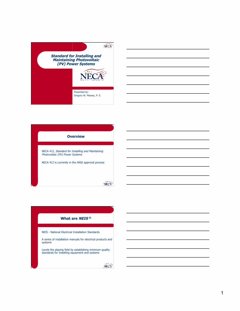
Standard for Installing and Maintaining Photovoltaic
(PV) Power Systems
Presented by: Gregory W. Massey, P. E.
Overview
NECA 412, Standard for Installing and Maintaining Photovoltaic (PV) Power Systems
NECA 412 is currently in the ANSI approval process
What are NEIS ®
NEIS - National Electrical Installation Standards
A series of installation manuals for electrical products and systems
Levels the playing field by establishing minimum quality standards for installing equipment and systems
2
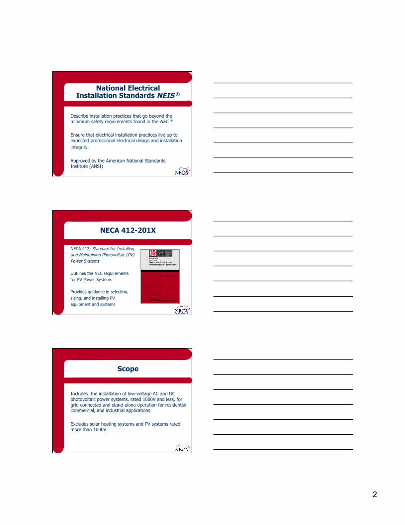
National Electrical Installation Standards NEIS ®
Describe installation practices that go beyond the minimum safety requirements found in the NEC ®
Ensure that electrical installation practices live up to expected professional electrical design and installation integrity.
Approved by the American National Standards Institute (ANSI)
NECA 412-201X
NECA 412, Standard for Installing and Maintaining Photovoltaic (PV) Power Systems
Outlines the NEC requirements for PV Power Systems
Provides guidance in selecting, sizing, and installing PV equipment and systems
Scope
Includes the installation of low-voltage AC and DC photovoltaic power systems, rated 1000V and less, for grid-connected and stand-alone operation for residential, commercial, and industrial applications
Excludes solar heating systems and PV systems rated more than 1000V

3
Scope
Conforms to NFPA 70, National Electrical Code, NFPA 70E, Standard for Electrical Safety, and other NEIS publications
Provides recommendations, rules of thumb, and tricks of the trade
Definitions
Solar cell. The basic photovoltaic device that generates electricity when exposed to light. This is the fundamental building block for PV power systems. Solar cells generate a DC voltage when exposed to sunlight.
Definitions
PV Module. A complete, environmentally protected unit consisting of solar cells, optics, and other components, exclusive of tracker, designed to generate dc power when exposed to sunlight. PV modules (or solar panels) are the smallest commercially-available PV power system component.

4
Definitions
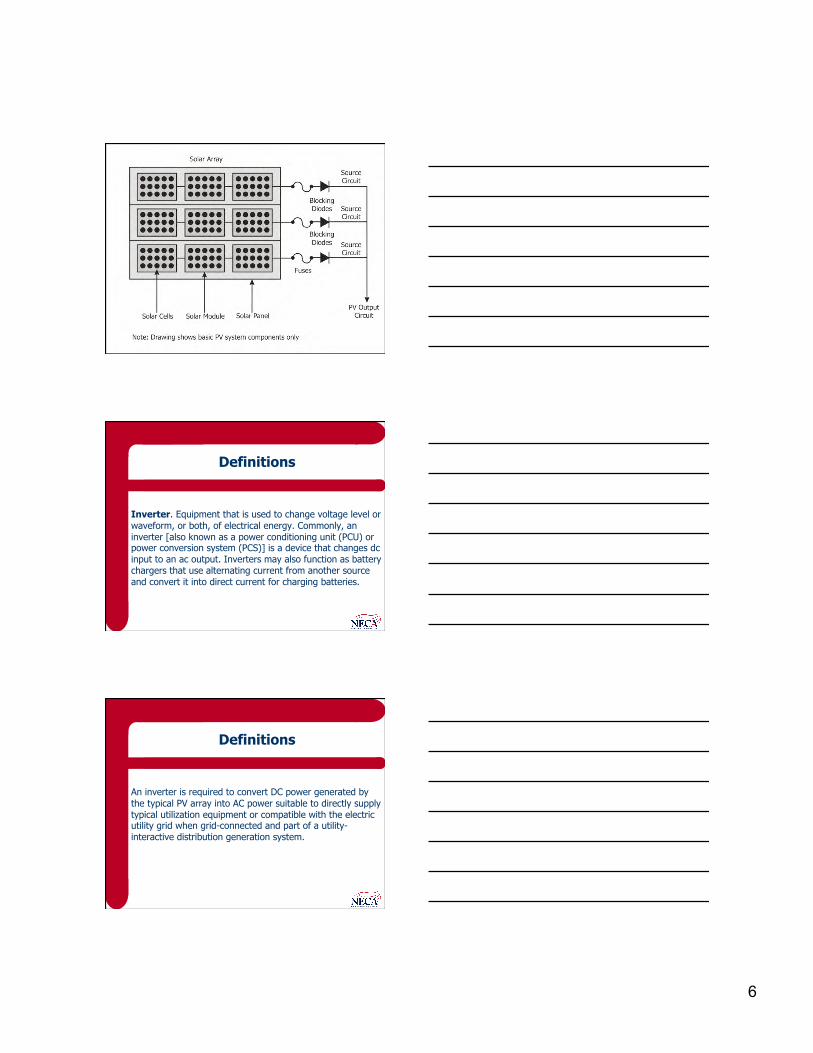
PV Array. A mechanically integrated assembly of modules or panels with a support structure and foundation, tracker, and other components as required, installed as a system to form a direct current power-producing unit. Solar modules are connected in series and parallel to create an array. The PV array includes the balance of mechanical components and the balance of electrical components to mount and interconnect the solar modules.
Definitions
Roof-mounted PV array
I-Stock photo courtesy of NECA
Definitions
Solar modules are connected in series to increase the voltage of the array. A string of (10) solar modules with a nominal voltage rating of 28Vdc would have a nominal voltage rating of 280Vdc. Solar modules are connected in series to increase the current of the array. An array of (4) strings of (10) solar modules from the above example with a current rating of 3.5A each would create a nominal 280Vdc array with a current rating of 14.0A.

5
Definitions
Photovoltaic Output Circuit. Circuit conductors between the photovoltaic source circuit(s) and the inverter or DC utilization equipment. The DC utilization equipment can be DC loads or energy storage battery charging equipment
Definitions
Photovoltaic Power Source. An array or aggregate of arrays that generates DC power at system voltage and current.
Definitions
Photovoltaic Source Circuit. Circuits between modules and from modules to the common connection point(s) of the DC system. Strings of modules are connected together at a “combiner box” (common connection point) that has overcurrent protection, frequently fuses, and blocking diodes that prevent current from flowing into a fault within the array.
6
Definitions
Inverter. Equipment that is used to change voltage level or waveform, or both, of electrical energy. Commonly, an inverter [also known as a power conditioning unit (PCU) or power conversion system (PCS)] is a device that changes dc input to an ac output. Inverters may also function as battery chargers that use alternating current from another source and convert it into direct current for charging batteries.
Definitions
An inverter is required to convert DC power generated by the typical PV array into AC power suitable to directly supply typical utilization equipment or compatible with the electric utility grid when grid-connected and part of a utility-interactive distribution generation system.

7
Definitions
Inverters connected in a PV power system Photo courtesy of Central Florida Electrical JATC
Definitions
Alternating-Current (AC) Module (Alternating-Current Photovoltaic Module). A complete, environmentally protected unit consisting of solar cells, optics, inverter, and other components, exclusive of tracker, designed to generate AC power when exposed to sunlight. AC PV modules have an integral inverter and generate AC power. The output of an AC PV module is considered to be the output of an inverter in applying NEC requirements.
Definitions
Inverter Input Circuit. Conductors between the inverter and the battery in stand-alone systems or the conductors between the inverter and the photovoltaic output circuits for electrical production and distribution network. The inverter input circuit can also be PV output circuit.

8
Definitions
Inverter Output Circuit. Conductors between the inverter and an AC panelboard for stand-alone systems or the conductors between the inverter and the service equipment or another electric power production source, such as a utility, for electrical production and distribution network.
Definitions
Utility-interactive inverter. An inverter intended for use in parallel operation with an electric utility to supply common loads that may deliver power to the utility. A utility-interactive inverter contains protection, monitoring, and controls that enable the PV array to operate in parallel with the electric utility grid.
Definitions
Inverter controls. Controls that regulate power conversion from DC to AC, synchronize to the electric utility grid, monitor bus voltage and frequency, and provide protection in the event of a fault, failure, or abnormal operating condition. Synchronization. Process of matching the operating voltage, frequency, and phase angle of one source to another source prior to paralleling the sources together.

9
Definitions
Interactive System. A solar photovoltaic system that operates in parallel with and may deliver power to an electrical production and distribution network. For the purpose of this definition, an energy storage subsystem of a solar photovoltaic system, such as a battery, is not another electrical production source. AKA – grid-connected or operating in parallel with the electric utility grid
Definitions
Electrical Production and Distribution Network. A power production, distribution, and utilization system, such as a utility system and connected loads, that is external to and not controlled by the photovoltaic power system. AKA – the electric utility grid
Definitions
Net metering. Utility billing practice that permits power delivery from distributed generation sources to the electric utility grid across the utility revenue meter. Frequently, net metering does not entail a direct payment from the electric utility company to the customer, but a credit for power generated in excess of power consumed on-site. This credit typically expires within a contractual time period.

10
Definitions
Power buy-back. Utility purchase of excess power from customer-owned distributed generation Agreement between the electric utility company and the customer to purchase excess power from customer-owned distributed generation. Typically used for relatively large-scale customer-owned generation, which may be 1,000kW or more.
Definitions
Stand-Alone System. A solar photovoltaic system that supplies power independently of an electrical production and distribution network. A stand-alone PV system operates independently of the electric utility grid. During times when a PV array is not generating power, such as at night, a stand-alone PV power system must have either one or more alternative power generation methods (Hybrid System) or energy storage batteries.
Definitions
Hybrid System. A system comprised of multiple power sources. These power sources may include photovoltaic, wind, micro-hydro generators, engine-driven generators, and others, but do not include electrical production and distribution network systems. Energy storage systems, such as batteries, do not constitute a power source for the purpose of this definition. Alternatively, a stand-alone PV system can use energy storage batteries, which require additional equipment and controls for battery charging.

11
Definitions
Battery Charger. A device that can maintain a unidirectional current in a battery in the opposite direction to that during discharge thereby converting electric energy into stored chemical energy within the battery. Charge Controller. Equipment that controls DC voltage or DC current, or both, used to charge a battery.
Definitions
Diversion Charge Controller. Equipment that regulates the charging process of a battery by diverting power from energy storage to direct-current or alternating-current loads or to an interconnected utility service. Protects batteries from overcharging by diverting power to a non-essential DC load, such as lighting.

12
Definitions
Insolation. The average solar energy that reaches the earth's surface at a given location per day, expressed as kilowatt-hours-per-square-meter per day (kWh/m2/day). Peak Sun Hours. The equivalent measure of total solar irradiation in a day.
Definitions
Solar Irradiation. The total amount of solar energy accumulated on an area over time, typically expressed as kilowatt-hours-per-square-meter (kWh/m2). Solar irradiation is the principle measurement used to quantify solar energy production over time.
Definitions
Tilt angle. The orientation angle of the solar array with respect to the horizon, expressed in degrees. Incident angle. Orientation angle of the sun with respect to the horizon, expressed in degrees.

13
Definitions
Azimuth. The orientation angle of the solar array with respect to solar south (0o) expressed in degrees. Sun position to the east of solar south is typically represented by a positive azimuth angle, where sun position to the west of solar south is typically represented by a negative azimuth angle.
Introduction
PV power systems convert sunlight (solar energy) into electric energy Individual solar cells convert sunlight into DC voltage Solar cells are electrically and mechanically interconnected to form solar panels
Introduction
Solar panels are connected in series and in parallel to form solar arrays Connecting solar panels in series increases voltage Connecting solar panels in parallel increases current Virtually any operating voltage and power rating can be achieved

14
Introduction
PV output circuits from each series string are connected to an overcurrent protective device, typically fuses, and blocking diodes, in a combiner box One set of DC output conductors from the combiner box are connected to the DC disconnecting means
Introduction
The DC output conductors from the DC disconnecting means can be used to supply: l DC loads directly l Energy storage batteries l An inverter input circuit with or without batteries Energy storage batteries require a battery charger, charge controller, or diversion charge controller

15
Introduction
A charger or charge controller regulates battery voltage and the charge or discharge current and protects batteries from damaging voltages, currents, and temperatures
Introduction
Most often, PV power systems supply utility-interactive inverters, are grid-connected, and supply AC loads Inverters convert DC voltage into an AC waveform that is compatible with AC loads Utility-interactive inverters are used to connect solar arrays to the electric utility grid
16
Introduction
Utility-interactive inverters: l Control the power transfer from the PV array to AC loads
and/or electric utility grid
l Protect the PV array from the electric utility grid
l Protect the electric utility grid from the PV array
Introduction
Utility-interactive inverters monitor the electric utility grid to ensure the one-way transfer of power from the PV array to the connected loads and/or to the electric utility grid
Introduction
Stand-alone PV power systems (that operate independently of the electric utility grid) must have either energy storage batteries or one or more alternative power generation sources, or both, to supply power to loads when solar power is not available, such as at night
17
PV System Operation
Power output from a PV power system follows a Bell curve, with the greatest output on a bright, sunny day with low ambient temperature PV power output drops off with sunlight intensity and with temperature
PV System Operation
PV power output is affected by: l Atmospheric conditions
l Ambient temperature
l Ground snow cover
PV System Operation
Solar PV power systems are a “passive” generation technology Only produce power when exposed to sunlight Cannot store electricity for later use unless equipped with energy storage batteries

18
PV System Operation
Grid-connected systems only produce power when the electric utility grid is operational Cannot increase power output in response to an increase in load Cannot predict PV power generation at any given point in time
PV System Operation
Can accurate predict PV power generation over time based on the local solar resource Insolation is the average solar energy density at a given location, expressed as kilowatt-hours per square meter per day (kWh/m2/day) Insolation data is used to calculate the average annual PV energy output of a given PV array
Pre-Installation Considerations
Electrical Contractor Responsibilities l Communication with manufacturers, vendors, suppliers,
utility, owner, inspector, others l Understand the types of PV systems and which type is to
be installed l Perform and accurate efficient site assessment of existing
power service

19
Pre-Installation Considerations
Electrical Contractor Responsibilities l Provide accurate and clear estimate of necessary
upgrades (if applicable) l Coordinate with the local electric utility company and
Authority Having Jurisdiction (AHJ) l Use expertise to ensure a positive customer experience
Pre-Installation Considerations
The Electrical Permit Process l Determine and contact the applicable AHJ l Determine the applicable NEC edition and other Codes
adopted and enforced by the AHJ l Verify if there are specific local amendments to the NEC
rules
Pre-Installation Considerations
The Electrical Permit Process l Verify the specific installation procedures and processes l Verify utility company requirements
– Separate revenue meter is required – Different rate tariff applies – Application forms and fees are required

20
Pre-Installation Considerations
The Role of the Inspector l Issuing construction/installation permits l Enforcement of the NEC and other Codes adopted within
their jurisdiction l Review of plans and specifications for Code compliance
Pre-Installation Considerations
The Role of the Inspector l Conduct field inspections l Issuing of non-compliance reports/inspectors notices l Notifying utility for connection or meter clearances l Issue approvals upon completion of project
Pre-Installation Considerations
Electrical Inspection Process l Coordinate and schedule the rough-in and final
inspections l NECA recommends setting up an on-site inspection
meeting to assist the inspector and to directly address any issues or concerns to expedite the inspection process
l Address all deficiencies that are identified by the inspector
l Maintain records of the inspection and approval process
21
Pre-Installation Considerations
Environmental considerations: l PV modules are relatively immune to rain, snow, sleet
and hail l PV power output increases with elevation l PV power output decreases with temperature
Pre-Installation Considerations
Building Codes, fire codes, and zoning requirements l Firefighter safety l Solar panel layout and arrangement l Access to disconnecting means l Overcurrent protection l Safety and warning labels
Pre-Installation Considerations
Permits l New PV systems on new structures l New PV systems on existing structures
Submittals l Greater than 5kW l Residential system that occupies more than 50% of the
roof area

22
Pre-Installation Considerations
Submittals – plan requirements: l Plans with locations and one-line diagrams with connections l Equipment data, sizing, ratings, Listing information and approvals l Equipment locations and laying with clearances, pathways, and access information
Pre-Installation Considerations
Utility Interconnection Requirements l Must comply with NEC Article 705.12 regarding the point
of connection (point of common coupling) l May require additional disconnecting means accessible to
electric utility company personnel l Labeling, metering, overcurrent protection, automatic
disconnection l Forms, fees, permits
Pre-Installation Considerations
Locating PV arrays l Full sun exposure l No obstructions, shading l Generally oriented toward solar south l Can orient slightly east or west, but not north l Roof-top installations – must meet access and required clearances for firefighting, smoke ventilation, etc.

23
Pre-Installation Considerations
Mounting options l Fixed mounted (flush-mounted, typically on a roof,
mounted on a static, tilt-up support structure, or pole-top mount)
l One-axis or two-axis tracking (specialized pole-top mount)
Pre-Installation Considerations
Flush roof-mounted Photo Courtesy of NEC, Copyright Rob Colgan
Pre-Installation Considerations
Structural support Framework Photo Courtesy of Central Florida Electrical JATC
24
Pre-Installation Considerations
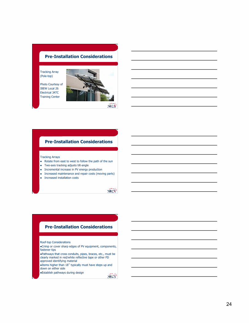
Tracking Array (Pole-top) Photo Courtesy of IBEW Local 26 Electrical JATC Training Center
Pre-Installation Considerations
Tracking Arrays l Rotate from east to west to follow the path of the sun l Two-axis tracking adjusts tilt-angle l Incremental increase in PV energy production l Increased maintenance and repair costs (moving parts) l Increased installation costs
Pre-Installation Considerations
Roof-top Considerations l Crimp or cover sharp edges of PV equipment, components, fastener tips l Pathways that cross conduits, pipes, braces, etc., must be clearly marked in red/white reflective tape or other FD approved identifying material l Items higher than 18” typically must have steps up and down on either side l Establish pathways during design

25
Pre-Installation Considerations
Access and Required Clearances l Residential Buildings
– Hip Roofs – provide (1) 36” wide clear access path from the eave to the ridge on each roof slope with PV panels
– Single Ridge – provide (2) 36” wide access pathways from the eave to the ridge on each roof slope with PV panels
Pre-Installation Considerations
Access and Required Clearances l Residential Buildings
– Hips and Valleys – 18” required clearance on both sides if both sides have PV panels; if PV panels are installed on only one side if of equal length, panels can be placed directly adjacent to the hip or valley
– Locate pathways at a structurally supported location, such as at a load bearing wall
Pre-Installation Considerations
Access and Required Clearances l Commercial Buildings and Residential Housing of Three or More Units
– Minimum 48” wide clear perimeter around the edges of the roof – Locate pathways over structural members – Provide centerline axis pathways in both axes of the roof – Provide straight-line pathways not less than 48” wide to skylights
and/or ventilation hatches – Provide straight-line pathways not less than 48” wide to roof-
mounted standpipes

26
Pre-Installation Considerations
Access and Required Clearances l Commercial Buildings and Residential Housing of Three or More Units
– Provide 48” minimum clearance around roof access hatches with a minimum of (1) 48” wide pathway to the parapet or roof edge
– Arrays must be no greater than 150’ in length in any direction to permit smoke ventilation
Pre-Installation Considerations
Access and Required Clearances l Commercial Buildings and Residential Housing of Three or More Units
– For smoke ventilation, provide a minimum 96” wide pathway between arrays, a minimum 48” wide pathway that borders roof skylights or ventilation hatches, or a minimum 48” wide pathway bordering 48” by 96” venting cutouts every 20’ on alternating sides of the pathway
Pre-Installation Considerations
Structural Systems l Flush-mounted roof-top l Universal tilt-up structural support (roof-mounted or
ground-mounted) l Pole-mounted (static) l Tracking array

27
Pre-Installation Considerations
Roof Mounting l Most likely to be flush-mounted (in the same plane as
the roof and less conspicuous than tilt-up structural framework)
l Least expensive, most simple installation l Self-ballasted systems do not require attachment to the
roof.
Pre-Installation Considerations
Roof Mounting l Metal brackets installed on each solar panel and secured
to the roof or low-profile mounting rails (to provide air circulation)
l Use stainless steel bolts and hardware, or J-bolts l When possible, install the PV array during the installation
of the roof. Otherwise, employ qualified roofing contractor to patch/repair mounting holes using approved materials and methods to maintain any warranties.
Pre-Installation Considerations
Roof Mounting l Flush-mounting offers no flexibility in solar array
orientation l Typically used for smaller PV power systems

28
Pre-Installation Considerations
Universal Tilt-Up Structural Support l Can be roof-mounted or ground-mounted l Typically non-moving (or static) l Used for larger solar arrays
Pre-Installation Considerations
Universal Tilt-Up Structural Support l When roof-mounted:
– More expensive than flush-mounted – Increase wind resistance – Typically present a challenge with local building codes – Provide flexibility with orientation and tilt-angle
l More likely to be ground-mounted
Pre-Installation Considerations
Pole-Top Mounting l PV array can be mounted to a structural framework
bolted to a sleeve and set on a pole embedded in concrete or earth
l Can be heavy l Can increase wind resistance
29
Pre-Installation Considerations
Tracking Array l Specialized pole-top mounting l PV array can rotate on the mounting pole (one-axis
tracking) and may also contain controls to control the tilt-angle of the support structure (two-axis tracking)
l Active tracking has motorize controls to adjust east-to-west array orientation
Pre-Installation Considerations
Tracking Array l Passive tracking has sealed tanks on each side with
interconnecting tubes and a liquid medium that rotates the array with no motors, gears, or exterior controls
l Tracking arrays increase PF power production by orienting the array more directly towards the sun during daylight hours
Pre-Installation Considerations
PV Power System Configuration: l Utility interactive system l Stand-alone system l Bimodal system l Hybrid system l Direct-coupled system

30
Pre-Installation Considerations
Utility-Interactive Systems (more common): l Operate in parallel with the electric utility grid l Utility-interactive inverter (control and protection) must
be Listed l Inverter monitors utility voltage and frequency and only
delivers power when the utility is stable l Sizing of the PV array is less critical as the electric utility
grid acts as a buffer - Example
Pre-Installation Considerations
PV Power System Performance Estimate (also see Annex A) l Cannot predict PV power generation at any given point in
time l Can accurately estimate PV power generation over time
PAEO = 365(IPSH)(PSAR)(0.77)
Pre-Installation Considerations
PV Power System Performance Estimate (also see Annex A) How do we find IPSH?
http://rredc.nrel.gov/solar/old_data/nsrdb/

31
Pre-Installation Considerations
Contains the 30-year average of monthly insolation data from 1961 through 1990 for select cities throughout the United States, and has an update for data from 1991 through 2005 Data tables found on this website include insolation data for various types of solar panels (flat plat and concentrating collectors) and mounting methods (fixed, one-axis tracking, and two-axis tracking)
Pre-Installation Considerations
Must consider tilt-angle of the array. Typically, tilt-angle is set to site-latitude to maximize year-round PV energy production. PV arrays can be tilted more vertically to increase PV power generation during winter months (sun low in the sky) or more horizontally to increase PV power generation during summer months (sun higher in the sky). Tilt-angle can also be adjusted periodically, such as quarterly, to maintain more optimal orientation towards the sun during the seasons.
Pre-Installation Considerations
Sizing Example: For a non-tracking (static) flat-collector PV panels oriented towards solar south at site latitude (to maximize year-round PV energy production) located in San Diego, CA, the year-round average IPSH is 5.9 peak sun hours per day.

32
Pre-Installation Considerations
Sizing Example: Plugging in to our formula gives:
PAEO = 365(5.9)(PSAR)(0.77) = (1658)(PSAR) Meaning that for every 1.0 kW of output power rating, a PV array will generate approximately 1,658 kWh of energy per year.
Pre-Installation Considerations
This information can be used to determine the PV energy production of a given-sized PV array, or the minimum-sized array needed to generate a given quantity of energy. For example, a 3.5kW array will generate approximately 5,803 kWh per year.
PAEO = (1658)(3.5) = 5,803 kWh
Pre-Installation Considerations
Additionally, the minimum-sized array needed to generate 20,000 kWh per year is 12.063 kW:
PSAR = (20,000)/(1658) = 12.063 kW

33
Pre-Installation Considerations
Changing any of the variables (location, tilt-angle, type of solar panel, static vs. tracking, etc) would change expected power production
Pre-Installation Considerations
Net Metering: l Common utility revenue meter l Monitors two-way power transfer l When on-site power generation exceeds the on-site
connected load, power is delivered to the electric utility grid
l When on-site connected load exceeds on-site power generation, power is delivered from the electric utility grid
Pre-Installation Considerations
Net Metering: l Utility billing is based on the net difference between
power delivered to the electric utility grid and power delivered to the customer from the electric utility grid
l The customer is charged or credited for the net flow of energy across the utility revenue meter
l Net metering agreements rarely have provisions for direct utility payments for any credits

34
Pre-Installation Considerations
Net Metering: l Net metering agreements typically provide a credit for
customer power generation in excess of on-site connected loads
l Such credits typically expire after a contractually-specified time period
l When net metering is not offered, it may be necessary to install a separate utility revenue meter for on-site power generation
Pre-Installation Considerations
Dual Metering: l PV systems are connected to the electric utility grid
through a separate meter l Frequently used for large-scale PV systems l Provides the ability to use different tariffs for the value of
energy
Safety
General: l PV panels generate voltage when exposed to sunlight l High open-circuit voltage l High voltage during low ambient temperature l High temperature inverter operation l Multiple sources of power has the potential for backfeeds
throughout the system l Energy storage batteries
35
Installation
General: l Review installation instructions l Install PV equipment in accordance with the listing
installation instructions l PV power system equipment must be identified and
Listed for the purpose l Comply with all warning and safety label
Installation
General: l Check physical dimensions l Identify where equipment will be installed l Check existing panels for sufficient space and capacity to
connect PV power systems
Installation
Arrays: l Develop a preliminary sketch of where solar panels will
be installed l Resolve conflicts prior to installation, giving precedence
to systems or equipment with a required slope or clearance
l Install away from equipment that will shade panels
36
Installation
Arrays: l Ensure adequate access and pathways around arrays l Check that the array open circuit voltage does not
exceed the voltage rating of inverters l Adjust the tilt angle to suit project requirements, such as
biasing to increase winter energy production or summer energy production
Installation
Inverters and Charge Controllers: l Verify that the total current and power of the array is
within the ratings of the inverter. Additional inverters may be required to meet the power capacity requirements
l Inverter and charge controller operation is greatly influenced by ambient temperature, airflow, exposure to sunlight, input voltage, input power and orientation of the heatsink fins
Installation
Inverters and Charge Controllers: l Locate inverters away from sources of heat, such as high ambient temperature, sunlight, etc., and ensure adequate clearance and proper airflow l Observe the manufacturer’s instructions for the mounting orientation, and derate inverters for mounting orientation other than vertical l Mount inverters and charge controllers before terminating conductors
37
Installation
Inverters and Charge Controllers: l Check that the PV source circuit impedance is within the inverter manufacturer’s recommended tolerances l Internal components may be energized and uninsulated, may move or rotate, and may be hot to the tough. Do not touch internal or external inverter or charge controller components during operation
Installation
Inverters and Charge Controllers: l Connect inverters and charge controllers to the electrical
power distribution system only after receiving authorization from the load electrical utility provider
Installation
Disconnecting Means: l Provide disconnecting means to disconnect all current-
carrying DC conductors of the PV power system, including inverters, batteries, charge controllers, etc. A disconnecting means is not required at the PV module or array location
l Group and identify disconnecting means for equipment energized from more than one source

38
Installation
Disconnecting Means: l PV disconnecting means are not require to be suitable as service equipment l PV disconnecting means must be manually operable switches or circuit breakers that are located where readily accessible either on the outside of a building or structure or inside nearest the point of entrance of the system conductors, and must be externally operable without exposing the operator to contact with live parts
Installation
Disconnecting Means: l PV disconnecting means must plainly indicate whether
they are in the open or closed position and must have sufficient interrupting rating for the nominal circuit voltage and the current that is available at the line terminals of the equipment
l Each PV disconnecting means must be permanently marked to identify it as a PV system disconnect
Installation
Disconnecting Means: l Where subject to a backfeed, disconnecting means must be labeled, “WARNING. ELECTRIC SHOCK HAZARD. DO NOT TOUGH TERMINALS. TERMINALS ON BOTH THE LINE AND LOAD SIDES MAY BE ENERGIZED IN THE OPEN POSITION” l Do not use fuses as a disconnecting means. When a fusible disconnect switch is used as disconnecting means, provide a second disconnecting means to de-energized fuses energized by a backfeed

39
Installation
Disconnecting Means: l Disconnecting means are required:
– To disconnect the PV power system from the electric utility grid – To disconnect energy storage batteries – To disconnect each array from the inverter or charge controller – To de-energized backfeed fuses
l Install a permanent plaque or directory that denotes all electric power sources at each service equipment location and at locations of all electric power sources capable of being interconnected
Installation
Disconnecting Means: l Always operate the AC disconnecting means to isolate
the PV power system from the electric utility grid before operating the DC disconnect at the inverter input circuit
Installation
Overcurrent Protection: l Overcurrent protective devices must be rated to carry
not less than 125 percent of the maximum circuit current, unless the device is rated for continuous operation at 100 percent of its rating
l Overcurrent protective devices must be listed for use in DC circuits when used in any DC portion of a PV system, and must have appropriate voltage, current and interrupt ratings

40
Installation
Overcurrent Protection: l Secure plug-in type overcurrent protective devices that are back-fed and used to terminate field-installed ungrounded supply conductors using an additional fastener that requires other than a pull to release the device l Do not backfeed circuit breakers that are marked “LINE” and “LOAD”

41
Installation
Conductors: l Verify that the total current and power of the array is
within the ratings of the inverter. Additional inverters may be required to meet the power capacity requirements
l PV circuits are defined in the NEC as continuous, where the maximum circuit current is expected to continue for 3 or more hours
Installation
Conductors: l Maximum circuit current for PV source and PV output
circuits is 125 percent of the sum of the parallel module rated short-circuit currents
l The maximum inverter output circuit current is the inverter continuous output current rating
Installation
Conductors: l Install conductors with ampacity of 125 percent of the
maximum circuit current without any additional correction factors for conditions of use, or with ampacity equal or greater than the maximum currents calculated after conditions of use have been applied
42
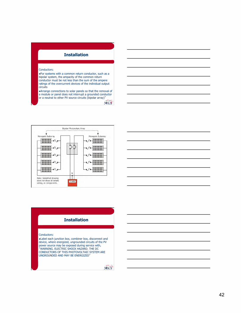
Installation
Conductors: l For systems with a common return conductor, such as a bipolar system, the ampacity of the common return conductor must be not less than the sum of the ampere ratings of the overcurrent devices of the individual output circuits l Arrange connections to solar panels so that the removal of a module or panel does not interrupt a grounded conductor or a neutral to other PV source circuits (bipolar array)”
Installation
Conductors: l Label each junction box, combiner box, disconnect and device, where energized, ungrounded circuits of the PV power source may be exposed during service with, “WARNING. ELECTRIC SHOCK HAZARD. THE DC CONDUCTORS OF THIS PHOTOVOLTAIC SYSTEM ARE UNGROUNDED AND MAY BE ENERGIZED”
43
NECA 412
Questions and Answers
Standard for Installing and Maintaining Photovoltaic
(PV) Power Systems
Presented by: Gregory W. Massey, P. E.