STANDARD FOR ACCEPTANCE - netaworld.org · Upon completion of this project, ... we offer the...
46
FOR ELECTRICAL POWER EQUIPMENT & SYSTEMS STANDARD FOR ACCEPTANCE TESTING SPECIFICATIONS ANSI/NETA ATS-2017
-
Upload
nguyendien -
Category
Documents
-
view
226 -
download
0
Transcript of STANDARD FOR ACCEPTANCE - netaworld.org · Upon completion of this project, ... we offer the...

FOR ELECTRICAL POWER EQUIPMENT & SYSTEMS
STANDARD FOR
ACCEPTANCETESTING SPECIFICATIONS
ANSI/NETA ATS-2017

ANSI/NETA ATS-2017
AMERICAN NATIONAL STANDARD
STANDARD FOR ACCEPTANCE TESTING SPECIFICATIONS for
Electrical Power Equipment and Systems
Secretariat InterNational Electrical Testing Association
American National Standards Institute

ANSI/NETA ATS-2017
– This page intentionally left blank –

ANSI/NETA ATS-2017 (Revision of ANSI/NETA ATS-2013)
21 May 2017 ANSI/NETA ATS-2017 Page 1 of 2
Errata to ANSI/NETA ATS-2017 Standard for Acceptance Testing Specifications for Electrical Power Equipment and Systems
Issued by the
NETA Standards Review Council
Of the
InterNational Electrical Testing Association
Correction sheet
Issued May 21, 2017
Copyright © 2017 by the InterNational Electrical Testing Association. All rights reserved. Published 2017.
Printed in the United States of America.
This correction sheet may be freely reproduced and distributed in order to maintain the utility and currency of the underlying Standard. This correction sheet may not be sold, licensed or otherwise distributed for any commercial purposes whatsoever. The content of this correction sheet may not be modified.
ANSI/NETA ATS-2017 (Revision of ANSI/NETA ATS-2013)
21 May 2017 ANSI/NETA ATS-2017 Page 2 of 2
7.2.2 Transformers, Liquid-Filled 7.2.2.B.7 Perform sweep frequency response analysis tests should be marked (*) as optional.
Original text incorrectly had the SFRA test as mandatory.
7.2.2 Transformers, Liquid-Filled 7.2.2.D.5 Change text to read investigate bushing power factor values that vary by more than 50%.
Original text is incorrectly shown as 150%.
Cables, Medium- and High-Voltage 7.3.3.B.4 TDR measurements should be marked (*) as optional.
Original text incorrectly had the TDR test as mandatory.
Circuit Breakers, Vacuum, Medium-Voltage 7.6.3.B.5 (electrical test) 7.6.3.D.5 (test result) Dynamic contact resistance test.
Delete requirement and expected test results section – this test was not intended for medium-
voltage vacuum breakers.

ANSI/NETA ATS-2017
American National Standard
Approval of an American National Standard requires verification by ANSI that the requirements for due process, consensus, and other criteria for approval have been met by the standards developer.
Consensus is established when, in the judgment of the ANSI Board of Standards Review, substantial agreement has been reached by directly and materially affected interests. Substantial agreement means much more than a simple majority, but not necessarily unanimity. Consensus requires that all views and objections be considered, and that a concerted effort be made toward their resolution.
The use of American National Standards is completely voluntary; their existence does not in any respect preclude anyone, whether he has approved the standards or not, from manufacturing, marketing, purchasing, or using products, processes, or procedures not conforming to the standards.
The American National Standards Institute does not develop standards and will in no circumstances give an interpretation of any American National Standard in the name of the American National Standards Institute. Requests for interpretations should be addressed to the secretariat or sponsor whose name appears on the title page of this standard.
Caution Notice: This American National Standard may be revised or withdrawn at any time. The procedures of the American National Standards Institute require that action be taken periodically to reaffirm, revise, or withdraw this standard. Purchasers of American National Standards may receive current information on all standards by calling or writing the American National Standards Institute.
Published by InterNational Electrical Testing Association 3050 Old Centre Ave., Suite 102 Portage, MI 49024 269.488.6382· FAX 269.488.6383 www.netaworld.org [email protected] Melissa Richard - Executive Director
Copyright© 2017 InterNational Electrical Testing Association All rights reserved Printed in the United States of America No part of this publication may be reproduced in any form, in an electronic retrieval system or otherwise, without the prior written permission of the publisher.
ANSI/NETA ATS-2017
Copyright Information and Alteration of Content
ANSI/NETA Standard for Acceptance Testing Specifications for Electrical Power Equipment and Systems, 2017 edition, (ANSI/NETA ATS-2017) is protected under the copyright laws of the United States, and all rights are reserved. Further, the ANSI/NETA ATS-2017 may not be copied, modified, sold, or used except in accordance with such laws and as follows: Purchasers may reproduce and use all or a portion of the ANSI/NETA ATS-2017 provided ANSI/NETA Standard for Acceptance Testing Specifications for Electrical Power Equipment and Systems are clearly identified in writing as the source of all such uses or reproductions. Section 7 of the ANSI/NETA Standard for Acceptance Testing Specifications for Electrical Power Equipment and Systems may be reproduced and used on a “cut and paste” basis for the particular type of equipment to be tested. The following sections of the ANSI/NETA Standard for Acceptance Testing Specifications for Electrical Power Equipment and Systems must be incorporated by reference as part of any subsection:
3. Qualifications of Testing Organization and Personnel 3.1 Testing Organization 3.2 Testing Personnel
4. Division of Responsibility 4.1 The Owner’s Representative 4.2 The Testing Organization
5. General 5.1 Safety and Precautions 5.2 Suitability of Test Equipment 5.3 Test Instrument Calibration 5.4 Test Report 5.5 Test Decal
The purchaser is required to include the above sections with any section(s) of 7.
© Copyright 2017 InterNational Electrical Testing Association
3050 Old Centre Avenue, Suite 102 Portage, MI 49024
E-mail: [email protected] • Web: www.netaworld.org

Standards Review Council
ANSI/NETA ATS-2017
These specifications were submitted for public comment and reviewed by the NETA Standards Review Council.
James G. Cialdea Timothy J. Cotter
Lorne J. Gara Roderic L. Hageman
Leif Hoegberg Daniel D. Hook
David G. Huffman Ralph E. Patterson Alan D. Peterson
Melissa A. Richard Kristen K. Wicks Ronald A. Widup
Ballot Pool Members
for ANSI/NETA Standard for Acceptance Testing Specifications for
Electrical Power Equipment and Systems, 2017 Edition
Ken Bassett Tom Bishop Scott Blizard
Michael Bowers John Cadick
Michel Castonguay James Dollard Peter Green
James Harvey Kerry Heid
Andrew Kobler Korey Kruse
Mark Lautenschlager Eric Nation Steve Park Lee Perry
Tony Perry Mose Ramieh
Diego Robalino Eddie Roland Randall Sagan
Mark Siira Jeremy Smith
Richard Sobhraj Charles Sweetser
Adis Talovic Alan Turpen Gary Walls John White
Jean-Pierre Wolff Chris Zavadlov

NOTICE
ANSI/NETA ATS-2017
In no event shall the InterNational Electrical Testing Association be liable to anyone for special, collateral, incidental, or consequential damages in connection with or arising out of the use of these materials.
This document is subject to periodic review, and users are cautioned to obtain the latest edition. Comments and suggestions are invited from all users for consideration by the Association in connection with such review. Any such suggestions will be fully reviewed by the Association after giving the commenter, upon request, a reasonable opportunity to be heard.
This document should not be confused with federal, state, or municipal specifications or regulations, insurance requirements, or national safety codes. While the Association recommends reference to or use of this document by government agencies and others, use of this document is purely voluntary and not binding.
InterNational Electrical Testing Association 3050 Old Centre Avenue, Suite 102 • Portage, MI 49024
Voice: 888.300.6382 Facsimile: 269.488.6383 Email: [email protected] • Web: www.netaworld.org
Melissa Richard - Executive Director

FOREWORD
(This Foreword is not part of American National Standard ANSI/NETA ATS-2017)
ANSI/NETA ATS-2017
The InterNational Electrical Testing Association (NETA) was formed in 1972 to establish uniform testing procedures for electrical equipment and apparatus. NETA developed specifications for the acceptance of new electrical apparatus prior to energization and for the maintenance of existing apparatus to determine its suitability to remain in service. The first NETA Acceptance Testing Specifications for Electrical Power Equipment and Systems was produced in 1972. Upon completion of this project, the NETA Technical Committee began work on a maintenance document, and Maintenance Testing Specifications for Electrical Power Equipment and Systems was published in 1975.
NETA has been an Accredited Standards Developer for the American National Standards Institute since 1996. NETA's scope of standards activity is different from that of the IEEE, NECA, NEMA, and UL. In matters of testing electrical equipment and systems NETA continues to reference other standards developers’ documents where applicable. NETA's review and updating of presently published standards takes into account both national and international standards. NETA’s standards may be used internationally as well as in the United States. NETA firmly endorses a global standardization. IEC standards as well as American consensus standards are taken into consideration by NETA's Section Panels and reviewing committees. The NETA Acceptance Testing Specifications was developed for use by those responsible for assessing the suitability for initial energization of electrical power equipment and systems and to specify field tests and inspections that ensure these systems and apparatus perform satisfactorily, minimizing downtime and maximizing life expectancy.
Since 1972, several revisions of the Acceptance Testing Specifications have been published; in 1989 the NETA Technical Committee, with approval of the Board of Directors, set a four-year review and revision schedule. Unless it involves a significant safety or urgent technical issue, each comment and suggestion for change is held until the appropriate review period. Each edition includes new and completely revised sections. The document uses the standard numbering system of ANSI and IEEE. Since 1989, revised editions of the Acceptance Testing Specifications have been published in 1991, 1995, 1999, 2003, 2007, 2009, and 2013. On February 2, 2017, the American National Standards Institute approved the NETA Acceptance Testing Specifications for Electrical Power Equipment and Systems as an American National Standard. Suggestions for improvement of this standard are welcome. They should be sent to the InterNational Electrical Testing Association, 3050 Old Centre Avenue, Suite 102, Portage, MI 49024, or emailed to [email protected].
PREFACE (This Preface is not part of American National Standard ANSI/NETA ATS-2017)
ANSI/NETA ATS-2017
It is recognized by the Association that the needs for acceptance testing of commercial, industrial, governmental, and other electrical power systems vary widely. Many criteria are used in determining what equipment is to be tested and to what extent. To help the user better understand and navigate more efficiently through this document, we offer the following information: Notation of Changes Material included in this edition of the document but not part of the 2013 edition is marked with a black vertical line to the left of the insertion of text, deletion of text, or alteration of text. The Document Structure The document is divided into thirteen separate and defined sections: Section Description Section 1 General Scope Section 2 Applicable References
Section 3 Qualifications of Testing Organization and Personnel Section 4 Division of Responsibility Section 5 General Section 6 Power System Studies Section 7 Inspection and Test Procedures Section 8 System Function Tests and Commissioning Section 9 Thermographic Survey Section 10 Electromagnetic Field Testing Section 11 Corona Studies (Reserved) Tables Reference Tables Appendices Various Informational Documents
Section 7 Structure Section 7 is the main body of the document with specific information on what to do relative to the inspection and acceptance testing of electrical power distribution equipment and systems. It is not intended that this document list how to test specific pieces of equipment or systems. Sequence of Tests and Inspections The tests and inspections specified in this document are not necessarily presented in chronological order and may be performed in a different sequence. Expected Test Results Section 7 consists of sections specific to each particular type of equipment. Within those sections there are, typically, four main bodies of information:
A. Visual and Mechanical Inspection B. Electrical Tests C. Test Values – Visual and Mechanical D. Test Values – Electrical

PREFACE (Continued) (This Preface is not part of American National Standard ANSI/NETA ATS-2017)
ANSI/NETA ATS-2017
Results of Visual and Mechanical Inspections Some, but not all, visual and mechanical inspections have an associated test value or result. Those items with an expected result are referenced under Section C., Test Values – Visual and Mechanical. For example, Section 7.1 Switchgear and Switchboard Assemblies, item 7.1.A.8.2 calls for verifying tightness of connections using a calibrated torque wrench method. Under the Test Values – Visual and Mechanical Section 7.1.C.2, the expected results for that particular task are listed within Section C., with reference back to the original task description on item 7.1.A.8.2.

PREFACE (Continued) (This Preface is not part of American National Standard ANSI/NETA ATS-2017)
ANSI/NETA ATS-2017
Results of Electrical Tests Each electrical test has a corresponding expected result, and the test and the result have identical numbers. If the electrical test is item four, the expected result under the Test Values section is also item four. For example, under Section 7.15.1 Rotating Machinery, AC Induction Motors and Generators, item 7.15.1.B.2 (item 2 within the Electrical Tests section) calls for performing an insulation-resistance test in accordance with IEEE Standard 43. In section D, Test Values – Electrical, the expected results for that particular task are listed in the Test Values section under item 2.

PREFACE (Continued) (This Preface is not part of American National Standard ANSI/NETA ATS-2017)
ANSI/NETA ATS-2017
Optional Tests The purpose of these specifications is to assure that all tested electrical equipment and systems supplied by either contractor or owner are operational and within applicable standards and manufacturer’s published tolerances and that equipment and systems are installed in accordance with design specifications. Certain tests are assigned an optional classification. The following considerations are used in determining the use of the optional classification:
1. Does another listed test provide similar information? 2. How does the cost of the test compare to the cost of other tests
providing similar information? 3. How commonplace is the test procedure? Is it new technology?
Manufacturer’s Instruction Manuals It is important to follow the recommendations contained in the manufacturer’s published data. Many of the details of a complete and effective testing procedure can be obtained from this source. Summary The guidance of an experienced testing professional should be sought when making decisions concerning the extent of testing. It is necessary to make an informed judgment for each particular system regarding how extensive a procedure is justified. The approach taken in these specifications is to present a comprehensive series of tests applicable to most industrial and larger commercial systems. In smaller systems, some of the tests can be deleted. In other cases, a number of the tests indicated as optional should be performed. Likewise, guidance of an experienced testing professional should also be sought when making decisions concerning the results of test data and their significance to the overall analysis of the device or system under test. Careful consideration of all aspects of test and calibration data, including manufacturer’s published data and recommendations, must be included in the overall assessment of the device or system under test. The Association encourages comment from users of this document. Please contact the NETA office or your local NETA Accredited Company.
Standards Review Council
InterNational Electrical Testing Association
James G. Cialdea Timothy J. Cotter
Lorne J. Gara Roderic L. Hageman
Leif Hoegberg Daniel D. Hook
David G. Huffman Ralph E. Patterson Alan D. Peterson
Melissa A. Richard Ronald A. Widup Kristen K. Wicks
ANSI/NETA ATS-2017
– This page intentionally left blank –

CONTENTS
ANSI/NETA ATS-2017
1. GENERAL SCOPE ...................................................................................................................... 1 2. APPLICABLE REFERENCES 2.1 Codes, Standards and Specifications ....................................................................... 2 2.2 Other References ..................................................................................................... 8 2.3 Contact Information ................................................................................................ 8 3. QUALIFICATIONS OF TESTING ORGANIZATION AND PERSONNEL 3.1 Testing Organization ................................................................................. 10 3.2 Testing Personnel ...................................................................................... 10 4. DIVISION OF RESPONSIBILITY 4.1 The Owner’s Representative ................................................................................. 11 4.2 The Testing Organization ...................................................................................... 11 5. GENERAL 5.1 Safety and Precautions .......................................................................................... 12 5.2 Suitability of Test Equipment ............................................................................... 12 5.3 Test Instrument Calibration ................................................................................... 13 5.4 Test Report ............................................................................................................ 14 5.5 Test Decal .............................................................................................................. 15 6. POWER SYSTEM STUDIES 6.1 Short-Circuit Studies ............................................................................................. 16 6.2 Coordination Studies ............................................................................................. 17 6.3 Arc-Flash Hazard Analysis ................................................................................... 18 6.4 Load-Flow Studies ................................................................................................ 20 6.5 Stability Studies ..................................................................................................... 21 6.6 Harmonic-Analysis Studies ................................................................................... 22 7. INSPECTION AND TEST PROCEDURES 7.1 Switchgear and Switchboard Assemblies ............................................................. 23 7.2.1.1 Transformers, Dry-Type, Air-Cooled, Low-Voltage, Small ................................. 28 7.2.1.2 Transformers, Dry-Type, Air-Cooled, Large ........................................................ 30 7.2.2 Transformers, Liquid-Filled .................................................................................. 33 7.3.1 Cables, Low-Voltage, Low-Energy - RESERVED............................................... 38 7.3.2 Cables, Low-Voltage, 600-Volt Maximum ........................................................... 39 7.3.3 Cables, Medium- and High-Voltage ..................................................................... 41 7.4 Metal-Enclosed Busways ...................................................................................... 44 7.5.1.1 Switches, Air, Low-Voltage .................................................................................. 46 7.5.1.2 Switches, Air, Medium-Voltage, Metal-Enclosed ................................................ 48 7.5.1.3 Switches, Air, Medium- and High-Voltage, Open ................................................ 51 7.5.2 Switches, Oil, Medium-Voltage ............................................................................ 54 7.5.3 Switches, Vacuum, Medium-Voltage ................................................................... 57 7.5.4 Switches, SF6, Medium-Voltage ........................................................................... 60 7.5.5 Switches, Cutouts .................................................................................................. 63 7.6.1.1 Circuit Breakers, Air, Insulated-Case/Molded-Case ............................................. 65 7.6.1.2 Circuit Breakers, Low-Voltage Power .................................................................. 68 7.6.1.3 Circuit Breakers, Air, Medium-Voltage ................................................................ 71 7.6.2 Circuit Breakers, Oil, Medium- and High-Voltage ............................................... 75 7.6.3 Circuit Breakers, Vacuum, Medium-Voltage ....................................................... 80 7.6.4 Circuit Breakers, SF6 ............................................................................................. 84 7.7 Circuit Switchers ................................................................................................... 88

CONTENTS
ANSI/NETA ATS-2017
7.8 Network Protectors, 600-Volt Class ......................................................................91 7.9.1 Protective Relays, Electromechanical and Solid-State ..........................................95 7.9.2 Protective Relays, Microprocessor-Based ...........................................................104 7.10.1 Instrument Transformers, Current Transformers .................................................107 7.10.2 Instrument Transformers, Voltage Transformers ................................................110 7.10.3 Instrument Transformers, Coupling-Capacitor Voltage Transformers ................112 7.10.4 Instrument Transformers, High-Accuracy Instrument Transformers (RESERVED) ..........................................................................................115 7.11.1 Metering Devices, Electromechanical and Solid-State ........................................116 7.11.2 Metering Devices, Microprocessor-Based ...........................................................117 7.12.1.1 Regulating Apparatus, Voltage, Step Voltage Regulators ...................................119 7.12.1.2 Regulating Apparatus, Voltage, Induction Regulators – WITHDRAWN ...........123 7.12.2 Regulating Apparatus, Current - RESERVED ....................................................124 7.12.3 Regulating Apparatus, Load Tap-Changers .........................................................125 7.13 Grounding Systems ..............................................................................................128 7.14 Ground-Fault Protection Systems, Low-Voltage .................................................130 7.15.1 Rotating Machinery, AC Induction Motors and Generators ................................133 7.15.2 Rotating Machinery, Synchronous Motors and Generators .................................137 7.15.3 Rotating Machinery, DC Motors and Generators ................................................142 7.16.1.1 Motor Control, Motor Starters, Low-Voltage ......................................................145 7.16.1.2 Motor Control, Motor Starters, Medium-Voltage................................................147 7.16.2.1 Motor Control, Motor Control Centers, Low-Voltage .........................................151 7.16.2.2 Motor Control, Motor Control Centers, Medium-Voltage ..................................152 7.17 Adjustable Speed Drive Systems .........................................................................153 7.18.1.1 Direct-Current Systems, Batteries, Flooded Lead-Acid ......................................156 7.18.1.2 Direct-Current Systems, Batteries, Vented Nickel-Cadmium .............................159 7.18.1.3 Direct-Current Systems, Batteries, Valve-Regulated Lead-Acid ........................161 7.18.2 Direct-Current Systems, Chargers .......................................................................163 7.18.3 Direct-Current Systems, Rectifiers - RESERVED ..............................................165 7.19.1 Surge Arresters, Low-Voltage .............................................................................166 7.19.2 Surge Arresters, Medium- and High-Voltage ......................................................168 7.20.1 Capacitors and Reactors, Capacitors....................................................................170 7.20.2 Capacitors and Reactors, Capacitor Control Devices - RESERVED ..................172 7.20.3.1 Capacitors and Reactors, Reactors (Shunt and Current-Limiting) Dry-Type .........................................................173 7.20.3.2 Capacitors and Reactors, Reactors (Shunt and Current-Limiting) Liquid-Filled ...................................................175 7.21 Outdoor Bus Structures ........................................................................................179 7.22.1 Emergency Systems, Engine Generator ...............................................................181 7.22.2 Emergency Systems, Uninterruptible Power Systems .........................................183 7.22.3 Emergency Systems, Automatic Transfer Switches ............................................186 7.23 Communications - RESERVED ..........................................................................189
7.24.1 Automatic Circuit Reclosers and Line Sectionalizers, Automatic Circuit Reclosers, Oil/Vacuum ..............................................190
7.24.2 Automatic Circuit Reclosers and Line Sectionalizers, Automatic Line Sectionalizers, Oil ..........................................................194
7.25 Fiber-Optic Cables ...............................................................................................197
CONTENTS
ANSI/NETA ATS-2017
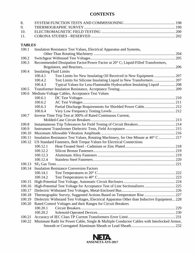
8. SYSTEM FUNCTION TESTS AND COMMISSIONING ..................................................... 198 9. THERMOGRAPHIC SURVEY ............................................................................................... 199 10. ELECTROMAGNETIC FIELD TESTING ............................................................................. 200 11. CORONA STUDIES - RESERVED ........................................................................................ 202 TABLES 100.1 Insulation Resistance Test Values, Electrical Apparatus and Systems, Other Than Rotating Machinery ..................................................................................... 204 100.2 Switchgear Withstand Test Voltages ........................................................................................ 205 100.3 Recommended Dissipation Factor/Power Factor at 20° C; Liquid-Filled Transformers, Regulators, and Reactors, ................................................................................................ 206 100.4 Insulating Fluid Limits 100.4.1 Test Limits for New Insulating Oil Received in New Equipment ...................... 207 100.4.2 Test Limits for Silicone Insulating Liquid in New Transformers ....................... 207 100.4.3 Typical Values for Less-Flammable Hydrocarbon Insulating Liquid ................ 208 100.5 Transformer Insulation Resistance, Acceptance Testing .......................................................... 209 100.6 Medium-Voltage Cables, Acceptance Test Values 100.6.1 DC Test Voltages ................................................................................................ 210
100.6.2 AC Test Voltages ................................................................................................ 211 100.6.3 Partial Discharge Requirements for Shielded Power Cable ................................ 212 100.6.4 Very Low Frequency Testing Levels .................................................................. 212 100.7 Inverse Time Trip Test at 300% of Rated Continuous Current, Molded-Case Circuit Breakers ........................................................................................ 213 100.8 Instantaneous Trip Tolerances for Field Testing of Circuit Breakers ....................................... 214 100.9 Instrument Transformer Dielectric Tests, Field Acceptance .................................................... 215 100.10 Maximum Allowable Vibration Amplitude .............................................................................. 216 100.11 Insulation Resistance Test Values, Rotating Machinery, for One Minute at 40° C ................. 217 100.12 US Standard Fasteners, Bolt Torque Values for Electrical Connections 100.12.1 Heat-Treated Steel - Cadmium or Zinc Plated .................................................... 218 100.12.2 Silicon Bronze Fasteners ..................................................................................... 219 100.12.3 Aluminum Alloy Fasteners ................................................................................. 219 100.12.4 Stainless Steel Fasteners ...................................................................................... 220 100.13 SF6 Gas Tests ............................................................................................................................ 221 100.14 Insulation Resistance Conversion Factors 100.14.1 Test Temperatures to 20° C ................................................................................. 222 100.14.2 Test Temperatures to 40° C ................................................................................. 223 100.15 High-Potential Test Voltage, Automatic Circuit Reclosers ...................................................... 224 100.16 High-Potential Test Voltage for Acceptance Test of Line Sectionalizers ................................ 225 100.17 Dielectric Withstand Test Voltages, Metal-Enclosed Bus ........................................................ 226 100.18 Thermographic Survey, Suggested Actions Based on Temperature Rise ................................ 227 100.19 Dielectric Withstand Test Voltages, Electrical Apparatus Other than Inductive Equipment ... 228 100.20 Rated Control Voltages and their Ranges for Circuit Breakers 100.20.1 Circuit Breakers ................................................................................................... 229 100.20.2 Solenoid-Operated Devices ................................................................................. 230 100.21 Accuracy of IEC Class TP Current Transformers Error Limit ................................................. 231 100.22 Minimum Radii for Power Cable, Single & Multiple Conductor Cables with Interlocked Armor, Smooth or Corrugated Aluminum Sheath or Lead Sheath .............................................. 232

CONTENTS
ANSI/NETA ATS-2017
APPENDICES Appendix A – Definitions ........................................................................................................................235 Appendix B – RESERVED .....................................................................................................................238 Appendix C – About the InterNational Electrical Testing Association ...................................................239 Appendix D – Form for Comments .........................................................................................................241 Appendix E – Form for Proposals ...........................................................................................................242

1. GENERAL SCOPE
Page 1 ANSI/NETA ATS-2017
1. These specifications cover the suggested field tests and inspections that are available to assess the suitability for initial energization and final acceptance of electrical power equipment and systems.
2. The purpose of these specifications is to assure that tested electrical equipment and systems are operational, are within applicable standards and manufacturer's tolerances, and are installed in accordance with design specifications.
3. The work specified in these specifications may involve hazardous voltages, materials, operations, and equipment. These specifications do not purport to address all of the safety issues associated with their use. It is the responsibility of the user to review all applicable regulatory limitations prior to the use of these specifications

2. APPLICABLE REFERENCES
2.1 Codes, Standards, and Specifications
Page 2 ANSI/NETA ATS-2017
All inspections and field tests shall be in accordance with the latest edition of the following codes, standards, and specifications except as provided otherwise herein.
1. American National Standards Institute – ANSI
2. ASTM International - ASTM
ASTM D92 Standard Test Method for Flash and Fire Points by Cleveland Open Cup Tester
ASTM D445 Standard Test Method for Kinematic Viscosity of Transparent and Opaque Liquids (the Calculation of Dynamic Viscosity)
ASTM D664 Standard Test Method for Acid Number of Petroleum Products by Potentiometric Titration
ASTM D877 Standard Test Method for Dielectric Breakdown Voltage of Insulating Liquids using Disk Electrodes
ASTM D923 Standard Practices for Sampling Electrical Insulating Liquids
ASTM D924 Standard Test Method for Dissipation Factor (or Power Factor) and Relative Permittivity (Dielectric Constant) of Electrical Insulating Liquids
ASTM D971 Standard Test Method for Interfacial Tension of Oil against Water by the Ring Method
ASTM D974 Standard Test Method for Acid and Base Number by Color-Indicator Titration
ASTM D1298 Standard Test Method for Density, Relative Density, or API Gravity of Crude Petroleum and Liquid Petroleum Products by Hydrometer Method
ASTM D1500 Standard Test Method for ASTM Color of Petroleum Products (ASTM Color Scale)
ASTM D1524 Standard Test Method for Visual Examination of Used Electrical Insulating Liquids in the Field
ASTM D1533 Standard Test Methods for Water in Insulating Liquids by Coulometric Karl Fischer Titration
ASTM D1816 Standard Test Method for Dielectric Breakdown Voltage of Insulating Liquids Using VDE Electrodes
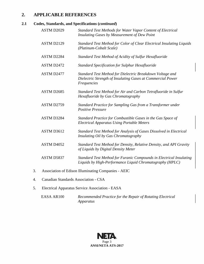
2. APPLICABLE REFERENCES
2.1 Codes, Standards, and Specifications (continued)
Page 3 ANSI/NETA ATS-2017
ASTM D2029 Standard Test Methods for Water Vapor Content of Electrical Insulating Gases by Measurement of Dew Point
ASTM D2129 Standard Test Method for Color of Clear Electrical Insulating Liquids (Platinum-Cobalt Scale)
ASTM D2284 Standard Test Method of Acidity of Sulfur Hexafluoride
ASTM D2472 Standard Specification for Sulphur Hexafluoride
ASTM D2477 Standard Test Method for Dielectric Breakdown Voltage and Dielectric Strength of Insulating Gases at Commercial Power Frequencies
ASTM D2685 Standard Test Method for Air and Carbon Tetrafluoride in Sulfur Hexafluoride by Gas Chromatography
ASTM D2759 Standard Practice for Sampling Gas from a Transformer under Positive Pressure
ASTM D3284 Standard Practice for Combustible Gases in the Gas Space of Electrical Apparatus Using Portable Meters
ASTM D3612 Standard Test Method for Analysis of Gases Dissolved in Electrical Insulating Oil by Gas Chromatography
ASTM D4052 Standard Test Method for Density, Relative Density, and API Gravity of Liquids by Digital Density Meter
ASTM D5837 Standard Test Method for Furanic Compounds in Electrical Insulating Liquids by High-Performance Liquid Chromatography (HPLC)
3. Association of Edison Illuminating Companies - AEIC
4. Canadian Standards Association - CSA
5. Electrical Apparatus Service Association - EASA
EASA AR100 Recommended Practice for the Repair of Rotating Electrical Apparatus

2. APPLICABLE REFERENCES
2.1 Codes, Standards, and Specifications (continued)
Page 4 ANSI/NETA ATS-2017
6. Institute of Electrical and Electronic Engineers - IEEE
IEEE C2 National Electrical Safety Code
IEEE C37 Compilation
Guides and Standards for Circuit Breakers, Switchgear, Relays, Substations, and Fuses
IEEE C57 Compilation
Distribution, Power, and Regulating Transformers
IEEE C62 Compilation
Surge Protection
IEEE C93.1 Requirements for Power-Line Carrier Coupling Capacitors and Coupling Capacitor Voltage Transformers (CCVT)
IEEE 43 IEEE Recommended Practice for Testing Insulation Resistance of Electric Machinery
IEEE 48 IEEE Standard for Test Procedures and Requirements for Alternating-Current Cable Terminations Used on Shielded Cables Having Laminated Insulation Rated 2.5 kV through 765 kV or Extruded Insulation Rated 2.5 kV through 500 kV
IEEE 81 IEEE Guide for Measuring Earth Resistivity, Ground Impedance, and Earth Surface Potentials of a Grounding System
IEEE 95 IEEE Recommended Practice for Insulation Testing of Large AC Rotating Machinery with High Direct Voltage
IEEE 100 The Authoritative Dictionary of IEEE Standards Terms
IEEE 141 IEEE Recommended Practice for Electrical Power Distribution for Industrial Plants (IEEE Red Book)
IEEE 142 IEEE Recommended Practice for Grounding of Industrial and Commercial Power Systems (IEEE Green Book)
IEEE 241 IEEE Recommended Practice for Electric Power Systems in Commercial Buildings (Gray Book)
IEEE 242 IEEE Recommended Practice for Protection and Coordination of Industrial and Commercial Power Systems (Buff Book)

2. APPLICABLE REFERENCES
2.1 Codes, Standards, and Specifications (continued)
Page 5 ANSI/NETA ATS-2017
IEEE 386 IEEE Standard for Separable Insulated Connector Systems for Power Distribution Systems above 600 V
IEEE 399 IEEE Recommended Practice for Power Systems Analysis (Brown Book)
IEEE 400 IEEE Guide for Field Testing and Evaluation of the Insulation of Shielded Power Cable Systems Rated 5 kV and Above
IEEE 400.1 IEEE Guide for Field Testing of Laminated Dielectric, Shielded Power Cable Systems Rated 5 kV and Above with High Direct Current Voltage
IEEE 400.2 IEEE Guide for Field Testing of Shielded Power Cable Systems Using Very Low Frequency (VLF)(less than 1 Hz)
IEEE 400.3 IEEE Guide for Partial Discharge Testing of Shielded Power Cable Systems in a Field Environment
IEEE 400.4 IEEE Guide for Field Testing of Shielded Power Cable Systems Rated 5 kV and Above with Damped Alternating Current (DAC) Voltage
IEEE 421.3 IEEE Standard for High-Potential-Test Requirements for Excitation Systems for Synchronous Machines
IEEE 446 IEEE Recommended Practice for Emergency and Standby Power Systems for Industrial and Commercial Applications (Orange Book)
IEEE 450 IEEE Recommended Practice for Maintenance, Testing, and Replacement of Vented Lead-Acid Batteries for Stationary Applications
IEEE 493 IEEE Recommended Practice for the Design of Reliable Industrial and Commercial Power Systems (Gold Book)
IEEE 519 IEEE Recommended Practices and Requirements for Harmonic Control in Electrical Power Systems
IEEE 602 IEEE Recommended Practice for Electric Systems in Health Care Facilities (White Book)
IEEE 637 IEEE Guide for the Reclamation of Insulating Oil and Criteria for Its Use
IEEE 644 Procedures for Measurement of Power Frequency Electric and Magnetic Fields from AC Power Lines

2. APPLICABLE REFERENCES
2.1 Codes, Standards, and Specifications (continued)
Page 6 ANSI/NETA ATS-2017
IEEE 739 IEEE Recommended Practice for Energy Management in Commercial and Industrial Facilities (Bronze Book)
IEEE 1015 IEEE Recommended Practice for Applying Low-Voltage Circuit Breakers Used in Industrial and Commercial Power Systems (Blue Book)
IEEE 1100 IEEE Recommended Practice for Powering and Grounding Sensitive Electronic Equipment (Emerald Book)
IEEE 1106 IEEE Recommended Practice for Maintenance, Testing, and Replacement of Nickel-Cadmium Batteries for Stationary Applications
IEEE 1159 IEEE Recommended Practice on Monitoring Electrical Power Quality
IEEE 1188 IEEE Recommended Practice for Maintenance, Testing, and Replacement of Valve-Regulated Lead-Acid (VRLA) Batteries for Stationary Applications
IEEE 1584 IEEE Guide for Arc-Flash Hazard Calculations
IEEE 3007.3 Recommended Practice for Electrical Safety in Industrial and Commercial Power Systems
7. Insulated Cable Engineers Association – ICEA
ICEA S-93-639/NEMA WC 74
5-46 kV Shielded Power Cable for Use in the Transmission and Distribution of Electric Energy
ICEA S-94-649
Standard for Concentric Neutral Cables Rated 5,000 - 46,000 Volts
ICEA S-97-682
Standard for Utility Shielded Power Cables Rated 5,000 - 46,000 Volts
8. InterNational Electrical Testing Association - NETA
ANSI/NETA ECS Standard for Electrical Commissioning of Electrical Power Equipment and Systems
ANSI/NETA ETT Standard for Certification of Electrical Testing Technicians
ANSI/NETA MTS Maintenance Testing Specifications for Electrical Power Equipment and Systems
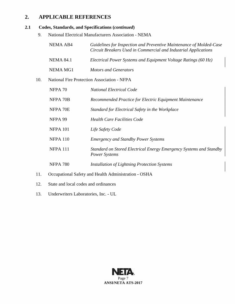
2. APPLICABLE REFERENCES
2.1 Codes, Standards, and Specifications (continued)
Page 7 ANSI/NETA ATS-2017
9. National Electrical Manufacturers Association - NEMA
NEMA AB4 Guidelines for Inspection and Preventive Maintenance of Molded-Case Circuit Breakers Used in Commercial and Industrial Applications
NEMA 84.1 Electrical Power Systems and Equipment Voltage Ratings (60 Hz)
NEMA MG1 Motors and Generators
10. National Fire Protection Association - NFPA
NFPA 70 National Electrical Code
NFPA 70B Recommended Practice for Electric Equipment Maintenance
NFPA 70E Standard for Electrical Safety in the Workplace
NFPA 99 Health Care Facilities Code
NFPA 101 Life Safety Code
NFPA 110 Emergency and Standby Power Systems
NFPA 111 Standard on Stored Electrical Energy Emergency Systems and Standby Power Systems
NFPA 780 Installation of Lightning Protection Systems
11. Occupational Safety and Health Administration - OSHA
12. State and local codes and ordinances
13. Underwriters Laboratories, Inc. - UL
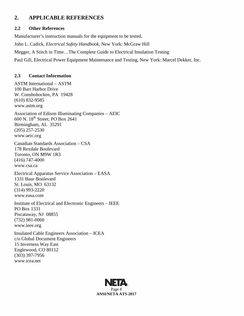
2. APPLICABLE REFERENCES
2.2 Other References
Page 8 ANSI/NETA ATS-2017
Manufacturer’s instruction manuals for the equipment to be tested.
John L. Cadick, Electrical Safety Handbook, New York: McGraw Hill
Megger, A Stitch in Time…The Complete Guide to Electrical Insulation Testing
Paul Gill, Electrical Power Equipment Maintenance and Testing, New York: Marcel Dekker, Inc.
2.3 Contact Information ASTM International – ASTM 100 Barr Harbor Drive W. Conshohocken, PA 19428 (610) 832-9585 www.astm.org
Association of Edison Illuminating Companies – AEIC 600 N. 18th Street; PO Box 2641 Birmingham, AL 35291 (205) 257-2530 www.aeic.org
Canadian Standards Association – CSA 178 Rexdale Boulevard Toronto, ON M9W 1R3 (416) 747-4000 www.csa.ca
Electrical Apparatus Service Association – EASA 1331 Baur Boulevard St. Louis, MO 63132 (314) 993-2220 www.easa.com
Institute of Electrical and Electronic Engineers – IEEE PO Box 1331 Piscataway, NJ 08855 (732) 981-0060 www.ieee.org
Insulated Cable Engineers Association – ICEA c/o Global Document Engineers 15 Inverness Way East Englewood, CO 80112 (303) 397-7956 www.icea.net
2. APPLICABLE REFERENCES
2.3 Contact Information (continued)
Page 9 ANSI/NETA ATS-2017
International Electrotechnical Commission – IEC Contact through American National Standards Institute
InterNational Electrical Testing Association – NETA 3050 Old Centre Avenue, Suite 102 Portage, MI 49024 (269) 488-6382 or (888) 300-NETA (6382) www.netaworld.org
Megger 4271 Bronze Way Dallas, TX 75237 (800) 723-2861 www.megger.com
National Electrical Manufacturers Association– NEMA 1300 N. 17th St. Suite 1847 Rosslyn, VA 22209 (703) 841-3200 www.nema.org
National Fire Protection Association – NFPA 1 Battery March Park PO Box 901 Quincy, MA 02269-9101 (617) 984-7247 www.nfpa.org
Occupational Safety and Health Administration – OSHA U.S. Department of Labor Occupational Safety and Health Administration Office of Public Affairs - Room N3647 200 Constitution Avenue Washington, D.C. 20210 (202) 693-1999 www.osha.gov
The Okonite Company 102 Hilltop Road Ramsey, New Jersey 07446 (201) 825-0300 Fax 201-825-3524 www.okonite.com
Underwriters Laboratories, Inc. – UL 333 Pfingsten Road Northbrook, IL 60062 (847) 272-8800 www.ul.com

3. QUALIFICATIONS OF TESTING ORGANIZATION AND PERSONNEL
3.1 Testing Organization
Page 10 ANSI/NETA ATS-2017
1. The testing organization shall be an independent, third party entity which can function as an unbiased testing authority, professionally independent of the manufacturers, suppliers, and installers of equipment or systems being evaluated.
2. The testing organization shall be regularly engaged in the testing of electrical equipment devices, installations, and systems.
3. The testing organization shall use technicians who are regularly employed for testing services.
4. An organization having a designation of NETA Accredited Company issued by the InterNational Electrical Testing Association meets the above criteria.
5. The testing organization shall submit appropriate documentation to demonstrate that it satisfactorily complies with these requirements.
3.2. Testing Personnel 1. Technicians performing these electrical tests and inspections shall be trained and experienced
concerning the apparatus and systems being evaluated. These individuals shall be capable of conducting the tests in a safe manner and with complete knowledge of the hazards involved. They must evaluate the test data and make a judgment on the serviceability of the specific equipment.
2. Technicians shall be certified in accordance with ANSI/NETA ETT, Standard for Certification of Electrical Testing Technicians. Each on-site crew leader shall hold a current certification, Level 3 or higher, in electrical testing.

4. DIVISION OF RESPONSIBILITY
Page 11 ANSI/NETA ATS-2017
4.1 The Owner’s Representative The owner’s representative shall provide the testing organization with the following:
1. A short-circuit analysis, a coordination study, and a protective device setting sheet as described in Section 6.
2. A complete set of electrical plans and specifications, including all change orders.
3. Drawings and instruction manuals applicable to the scope of work.
4. An itemized description of equipment to be inspected and tested.
5. A determination of who shall provide a suitable and stable source of electrical power to each test site.
6. A determination of who shall perform certain preliminary low-voltage insulation-resistance, continuity, and low-voltage motor rotation tests prior to and in addition to tests specified herein.
7. Notification of when equipment becomes available for acceptance tests. Work shall be coordinated to expedite project scheduling.
8. Site-specific hazard notification and safety training.
4.2 The Testing Organization The testing organization shall provide the following:
1. All field technical services, tooling, equipment, instrumentation, and technical supervision to perform such tests and inspections.
2. Specific power requirements for test equipment.
3. Notification to the owner’s representative prior to commencement of any testing.
4. A timely notification of any system, material, or workmanship that is found deficient based on the results of the acceptance tests.
5. A written record of all tests and a final report.

5. GENERAL
5.1 Safety and Precautions
Page 12 ANSI/NETA ATS-2017
All parties involved must be cognizant of industry-standard safety procedures. This document does not contain any procedures including specific safety procedures. It is recognized that an overwhelming majority of the tests and inspections recommended in these specifications are potentially hazardous. Individuals performing these tests shall be qualified and capable of conducting the tests in a safe manner and with complete knowledge of the hazards involved.
1. Safety practices shall include, but are not limited to, the following requirements:
1. All applicable provisions of the Occupational Safety and Health Act, particularly OSHA 29 CFR Part 1910 and 29 CFR Part 1926.
2. ANSI/NFPA 70E, Standard for Electrical Safety in the Workplace.
3. Applicable state and local safety operating procedures.
4. Owner’s safety practices.
2. The testing organization shall have a designated safety lead person on site to supervise operations with respect to safety.
3. A job hazard analysis and a safety briefing shall be conducted prior to the commencement of work.
4. All tests shall be performed with the apparatus de-energized and grounded except where otherwise specifically required to be ungrounded or energized for certain tests.
5. The testing organization shall have a designated safety representative on the project to supervise operations with respect to safety. This individual may be the same person described in 5.1.2.
5.2 Suitability of Test Equipment 1. All test equipment shall meet the requirements in Section 5.3 and be in good mechanical and
electrical condition.
2. Field test metering used to check power system meter calibration must be more accurate than the instrument being tested.
3. Accuracy of metering in test equipment shall be appropriate for the test being performed.
4. Waveshape and frequency of test equipment output waveforms shall be appropriate for the test to be performed and the equipment to be tested.

5. GENERAL
5.3 Test Instrument Calibration
Page 13 ANSI/NETA ATS-2017
1. The testing organization shall have a calibration program which assures that all applicable test instruments are maintained within rated accuracy for each test instrument calibrated.
2. The firm providing calibration service shall maintain up-to-date instrument calibration instructions and procedures for each test instrument calibrated.
3. The accuracy shall be directly traceable to the National Institute of Standards and Technology (NIST).
4. Instruments shall be calibrated in accordance with the following frequency schedule:
1. Field instruments: Analog and Digital, 12 months maximum.
2. Laboratory instruments: 12 months maximum.
3. Leased specialty equipment: 12 months maximum.
5. Dated calibration labels shall be visible on all test equipment.
6. Records which show date and results of instruments calibrated or tested must be kept up to date.
7. Calibrating standard shall be of better accuracy than that of the instrument tested.

5. GENERAL
5.4 Test Report
Page 14 ANSI/NETA ATS-2017
1. The test report shall include the following:
1. Summary of project.
2. Description of equipment tested.
3. Description of tests.
4. Device settings.
5. Test data.
6. Analysis and recommendations.
2. Test data records shall include the following minimum requirements:
1. Identification of the testing organization.
2. Equipment identification.
3. Nameplate data.
4. Humidity, temperature, and other conditions that may affect the results of the tests and/or calibrations.
5. Date of inspections, tests, maintenance, and/or calibrations.
6. Identification of the testing technician.
7. Indication of inspections, tests, maintenance, and/or calibrations to be performed and recorded.
8. Indication of expected results when calibrations are to be performed.
9. Indication of as-found and as-left results, as applicable.
10. Identification of all test results outside of specified tolerances.
11. Sufficient spaces to allow all results and comments to be indicated.
3. The testing organization shall furnish a copy or copies of the complete report as specified in the acceptance testing contract.

5. GENERAL
5.5 Test Decal
Page 15 ANSI/NETA ATS-2017
1. The testing organization shall affix a test decal on the exterior of equipment or equipment enclosure of protective devices after performing electrical tests.
2. The test decal shall be color-coded to communicate the condition of maintenance for the protective device. Color scheme for condition of maintenance of overcurrent protective device shall be:
1. White: electrically and mechanically acceptable.
2. Yellow: minor deficiency not affecting fault detection and operation, but minor electrical or mechanical condition exists.
3. Red: deficiency exists affecting performance, not suitable for service.
3. The decal shall include:
1. Testing organization
2. Project identifier
3. Test date
4. Technician identifier

6. POWER SYSTEM STUDIES
6.1 Short-Circuit Studies
* Optional
Page 16 ANSI/NETA ATS-2017
1. Scope of Study Determine the short-circuit current available at each component of the electrical system and the ability of the component to withstand and/or interrupt the current. Provide an analysis of all possible operating scenarios which will be or have been influenced by the proposed or completed additions or changes to the subject system.
2. Procedure The short-circuit study shall be performed in accordance with the recommended practices and procedures set forth in ANSI/IEEE 399 and the step-by-step procedures outlined in the short-circuit calculation chapters of IEEE 141 and ANSI/IEEE 242.
3. Study Report Results of the short-circuit study shall be summarized in a final report containing the following items:
1. Basis, description, purpose, and scope of the study.
2. Tabulations of the data used to model the system components and a corresponding one-line diagram.
3. Descriptions of the scenarios evaluated and identification of the scenario used to evaluate equipment short-circuit current ratings.
4. Tabulations of equipment short-circuit current ratings versus available fault duties. The tabulation shall identify percentage of rated short circuit current and clearly note equipment with insufficient ratings.
5. Conclusions and recommendations.

6. POWER SYSTEM STUDIES
6.2 Coordination Studies
* Optional
Page 17 ANSI/NETA ATS-2017
1. Scope of Study 1. Determine the extent of overcurrent protective device coordination for the scope:
1. Selective coordination: determine the protective device types, characteristics, settings, or ampere ratings which provide selective coordination, equipment protection, and correct interrupting ratings for the full range of available short-circuit currents at points of application for each overcurrent protective device.
2. Compromised coordination: determine protective device types, characteristics, settings, or ampere ratings which permit ranges of non-coordination of overcurrent protective devices. In this case, overcurrent protective device coordination may be compromised due to the overcurrent protective devices selected or already installed or in order to achieve protection of equipment that is selected or already installed. Objective is to maximize coordination of overcurrent protective devices to extent possible based on the type of devices. Determine protective device characteristics, settings, or sizes which provide a balance between equipment protection and selective device operation that is optimum for the electrical system.
2. Provide an analysis of all possible operating scenarios which will be or have been influenced by the proposed or completed additions or changes to the subject system. The coordination study shall be performed in accordance with the recommended practices and procedures set forth in ANSI/IEEE 399 and ANSI/IEEE 242. Protective device selection and settings shall comply with requirements of NFPA 70 National Electrical Code.
3. Study Report Results of the coordination study shall be summarized in a final report containing the following items:
1. Basis, description, purpose, and scope of the study and a corresponding one-line diagram.
2. Time-current curves, selective coordination ratios of fuses, or selective coordination tables of circuit breakers demonstrating the coordination of overcurrent protective devices to the scope.
3. Tabulations of protective devices identifying circuit location, manufacturer, type, range of adjustment, IEEE device number, current transformer ratios, recommended settings or device size, and referenced time-current curve.
4. Conclusions and recommendations.

6. POWER SYSTEM STUDIES
6.3 Arc-Flash Hazard Analysis
* Optional
Page 18 ANSI/NETA ATS-2017
1. Scope of Study
Determine arc-flash incident energy levels and flash-protection boundary distances based on the results of the short-circuit and coordination studies. Perform the analysis under worst-case arc-flash conditions for all modes of operation. Provide an analysis of all possible operating scenarios which will be or have been influenced by the proposed or completed additions to the subject system.
2. Procedure Identify all locations and equipment to be included in the arc-flash hazard analysis.
1. Prepare a one-line diagram of the power system.
2. Perform a short-circuit study in accordance with Section 6.1.
3. Perform a coordination study in accordance with Section 6.2.
4. Identify the possible system operating modes including tie-breaker positions, and parallel generation.
5. Calculate the arcing fault current flowing through each branch for each fault location in accordance with NFPA 70E, IEEE 1584, OSHA 1910.269, or other applicable standards.
6. Determine the time required to clear the arcing fault current using the protective device settings and associated trip curves.
7. Select the working distances based on system voltage and equipment class.
8. Calculate the incident energy at each fault location at the prescribed working distance.
9. Determine the arc-flash hazard PPE category for the calculated incident energy level.
10. Calculate the flash protection boundary at each fault location.
11. Document the assessment in reports and one-line diagrams.
*12. Fabricate and install appropriate labels on the equipment.

6. POWER SYSTEM STUDIES
6.3 Arc-Flash Hazard Analysis (continued)
* Optional
Page 19 ANSI/NETA ATS-2017
3. Study Report Results of the arc-flash study shall be summarized in a final report containing the following items:
1. Basis, method of hazard assessment, description, purpose, scope, and date of the study.
2. Tabulations of the data used to model the system components and a corresponding one-line diagram.
3. Descriptions of the scenarios evaluated and identification of the scenario used to develop incident-energy levels and arc-flash boundaries.
4. Tabulations of equipment incident energies, arc-flash hazard PPE categories, and arc-flash boundaries. The tabulation shall identify and clearly note equipment that exceeds 40 cal/cm2.
5. List of required arc-flash labels and locations.
6. Conclusions and recommendations.

6. POWER SYSTEM STUDIES
6.4 Load-Flow Studies
* Optional
Page 20 ANSI/NETA ATS-2017
1. Scope of Study Determine active and reactive power, voltage, current, and power factor throughout the electrical system. Provide an analysis of all possible operating scenarios.
2. Procedure The load-flow study shall be performed in accordance with the recommended practices and procedures set forth in ANSI/IEEE 399.
3. Study Report Results of the load-flow study shall be summarized in a final report containing the following items:
1. Basis, description, purpose, and scope of the study.
2. Tabulations of the data used to model the system components and a corresponding one-line diagram.
3. Descriptions of the scenarios evaluated and the basis for each.
4. Tabulations of power and current flow versus equipment ratings. The tabulation shall identify percentage of rated load and the scenario for which the percentage is based. Overloaded equipment shall be clearly noted.
5. Tabulations of system voltages versus equipment ratings. The tabulation shall identify percentage of rated voltage and the scenario for which the percentage is based. Voltage levels outside the ranges recommended by equipment manufacturers, ANSI/IEEE C84.1, or other appropriate standards shall be clearly noted.
6. Tabulations of system real and reactive power losses with areas of concern clearly noted.
7. Conclusions and recommendations.

6. POWER SYSTEM STUDIES
6.5 Stability Studies
* Optional
Page 21 ANSI/NETA ATS-2017
1. Scope of Study
Determine the ability of the electrical system’s synchronous machines to remain in step with one another following a disturbance. Provide an analysis of disturbances for all possible operating scenarios which will be or have been influenced by the proposed or completed additions or changes to the subject system.
2. Procedure The stability study shall be performed in accordance with the recommended practices and procedures set forth in ANSI/IEEE 399.
3. Study Report Results of the stability study shall be summarized in a final report containing the following items:
1. Basis, description, purpose, and scope of the study.
2. Tabulations of the data used to model the system components and a corresponding one-line diagram.
3. Descriptions of the scenarios evaluated and tabulations or graphs showing the calculation results.
4. Conclusions and recommendations.

6. POWER SYSTEM STUDIES
6.6 Harmonic-Analysis Studies
* Optional
Page 22 ANSI/NETA ATS-2017
1. Scope of Study
Determine the impact of nonlinear loads and their associated harmonic contributions on the voltage and currents throughout the electrical system. Provide an analysis of all possible operating scenarios which will be or have been influenced by the proposed or completed additions or changes to the subject system.
2. Procedure The harmonic-analysis study shall be performed in accordance with the recommended practices and procedures set forth in ANSI/IEEE 399.
3. Study Report Results of the harmonic-analysis study shall be summarized in a final report containing the following items:
1. Basis, description, purpose, and scope of the study.
2. Tabulations of the data used to model the system components and a corresponding one-line diagram.
3. Descriptions of the scenarios evaluated and the basis for each.
4. Tabulations of rms voltages, peak voltages, rms currents, and total capacitor bank loading versus associated equipment ratings. Equipment with insufficient ratings shall be clearly identified for each of the scenarios evaluated.
5. Tabulations of calculated voltage-distortion factors, current-distortion factors, and individual harmonics versus the limits specified by ANSI/IEEE 519. Calculated values exceeding the limits specified in the standard shall be clearly noted.
6. Plots of impedance versus frequency showing resonant frequencies to be avoided.
7. Tabulations of the system transformer capabilities based on the calculated nonsinusoidal load current and the procedures set forth in ANSI/IEEE C57.110. Overloaded transformers shall be clearly noted.
8. Conclusions and recommendations.

7. INSPECTION AND TEST PROCEDURES
7.1 Switchgear and Switchboard Assemblies
* Optional
Page 23 ANSI/NETA ATS-2017
A. Visual and Mechanical Inspection 1. Compare equipment nameplate data with drawings and specifications.
2. Inspect physical and mechanical condition.
3. Inspect anchorage, alignment, grounding, and required area clearances.
4. Verify the unit is clean and all shipping bracing, loose parts, and documentation shipped inside cubicles have been removed.
5. Verify that fuse and circuit breaker sizes and types correspond to drawings and coordination study as well as to the circuit breaker’s address for microprocessor-communication packages.
6. Verify that current and voltage transformer ratios correspond to drawings.
7. Verify that wiring connections are tight and that wiring is secure to prevent damage during routine operation of moving parts.
8. Inspect bolted electrical connections for high resistance using one or more of the following methods:
1. Use of a low-resistance ohmmeter in accordance with Section 7.1.B.1.
2. Verify tightness of accessible bolted electrical connections by calibrated torque-wrench method in accordance with manufacturer’s published data or Table 100.12.
3. Perform thermographic survey in accordance with Section 9.
9. Verify operation and sequencing of interlocking systems.
10. Verify appropriate lubrication on moving current-carrying parts and on moving and sliding surfaces.
11. Inspect insulators for evidence of physical damage or contaminated surfaces.
12. Verify correct barrier and shutter installation and operation.
13. Exercise all active components.
14. Inspect mechanical indicating devices for correct operation.
15. Verify that filters are in place and vents are clear.
16. Perform visual and mechanical inspection of instrument transformers in accordance with Section 7.10.

7. INSPECTION AND TEST PROCEDURES
7.1 Switchgear and Switchboard Assemblies (continued)
* Optional
Page 24 ANSI/NETA ATS-2017
17. Perform visual and mechanical inspection of surge arresters in accordance with Section 7.19.
18. Inspect control power transformers.
1. Inspect for physical damage, cracked insulation, broken leads, tightness of connections, defective wiring, and overall general condition.
2. Verify that primary and secondary fuse or circuit breaker ratings match drawings.
3. Verify correct functioning of drawout disconnecting contacts, grounding contacts, and interlocks.
B. Electrical Tests 1. Perform resistance measurements through bolted electrical connections with a low-resistance
ohmmeter, if applicable, in accordance with Section 7.1.A.8.1.
2. Perform insulation-resistance tests on each bus section, phase-to-phase and phase-to-ground, for one minute in accordance with Table 100.1.
3. Perform a dielectric withstand voltage test on each bus section, each phase-to-ground with phases not under test grounded, in accordance with manufacturer’s published data. If manufacturer has no recommendation for this test, it shall be in accordance with Table 100.2. The test voltage shall be applied for one minute.
*4. Perform insulation-resistance tests on control wiring with respect to ground. Applied potential shall be 500 volts dc for 300-volt rated cable and 1000 volts dc for 600-volt rated cable. Test duration shall be one minute. For units with solid-state components or control devices that can not tolerate the applied voltage, follow the manufacturer’s recommendation.
5. Perform electrical tests on instrument transformers in accordance with Section 7.10.
6. Perform ground-resistance tests in accordance with Section 7.13.
7. Test metering devices in accordance with Section 7.11.
8. Control Power Transformers
1. Perform insulation-resistance tests. Perform measurements from winding-to-winding and each winding-to-ground. Test voltages shall be in accordance with Table 100.1 unless otherwise specified by the manufacturer.
2. Perform a turns-ratio test on all tap positions.
3. Perform secondary wiring integrity test. Disconnect transformer at secondary terminals and connect secondary wiring to a rated secondary voltage source. Verify correct potential at all devices.

7. INSPECTION AND TEST PROCEDURES
7.1 Switchgear and Switchboard Assemblies (continued)
* Optional
Page 25 ANSI/NETA ATS-2017
4. Verify correct secondary voltage by energizing the primary winding with system voltage. Measure secondary voltage with the secondary wiring disconnected.
5. Verify correct function of control transfer relays located in the switchgear with multiple control power sources.
9. Voltage Transformers
1. Perform secondary wiring integrity test. Verify correct potential at all devices.
2. Verify secondary voltages by energizing the primary winding with system voltage.
10. Perform current-injection tests on the entire current circuit in each section of switchgear.
1. Perform current tests by secondary injection with magnitudes such that a minimum current of 1.0 ampere flows in the secondary circuit. Verify correct magnitude of current at each device in the circuit.
*2. Perform current tests by primary injection with magnitudes such that a minimum of 1.0 ampere flows in the secondary circuit. Verify correct magnitude of current at each device in the circuit.
11. Perform system function tests in accordance with ANSI/NETA ECS.
12. Verify operation of cubicle switchgear/switchboard space heaters.
13. Perform phasing checks on double-ended or dual-source switchgear to insure correct bus phasing from each source.
14. Perform electrical tests of surge arresters in accordance with Section 7.19.

7. INSPECTION AND TEST PROCEDURES
7.1 Switchgear and Switchboard Assemblies (continued)
* Optional
Page 26 ANSI/NETA ATS-2017
C. Test Values – Visual and Mechanical
1. Compare bolted connection resistance values to values of similar connections. Investigate values which deviate from those of similar bolted connections by more than 50 percent of the lowest value. (7.1.A.8.1)
2. Bolt-torque levels shall be in accordance with manufacturer’s published data. In the absence of manufacturer’s published data, use Table 100.12. (7.1.A.8.2)
3. Results of the thermographic survey shall be in accordance with Section 9. (7.1.A.8.3)
D. Test Values – Electrical
1. Compare bolted connection resistance values to values of similar connections. Investigate values which deviate from those of similar bolted connections by more than 50 percent of the lowest value.
2. Insulation-resistance values of bus insulation shall be in accordance with manufacturer’s published data. In the absence of manufacturer’s published data, use Table 100.1. Values of insulation resistance less than this table or manufacturer’s recommendations should be investigated. Dielectric withstand voltage tests shall not proceed until insulation-resistance levels are raised above minimum values.
3. If no evidence of distress or insulation failure is observed by the end of the total time of voltage application during the dielectric withstand test, the test specimen is considered to have passed the test.
4. Minimum insulation-resistance values of control wiring shall not be less than two megohms.
5. Results of electrical tests on instrument transformers shall be in accordance with Section 7.10.
6. Results of ground-resistance tests shall be in accordance with Section 7.13.
7. Accuracy of metering devices shall be in accordance with Section 7.11.
7. INSPECTION AND TEST PROCEDURES
7.1 Switchgear and Switchboard Assemblies (continued)
* Optional
Page 27 ANSI/NETA ATS-2017
8. Control Power Transformers
1. Insulation-resistance values of control power transformers shall be in accordance with manufacturer’s published data. In the absence of manufacturer’s published data, use Table 100.1. Values of insulation resistance less than this table or manufacturer’s recommendations should be investigated.
2. Turns-ratio test results shall not deviate by more than one-half percent from either the adjacent coils or the calculated ratio.
3. Secondary wiring shall be in accordance with design drawings and specifications.
4. Secondary voltage shall be in accordance with design specifications.
5. Control transfer relays shall perform as designed.
9. Voltage transformers
1. Secondary wiring shall be in accordance with design drawings and specifications.
2. Secondary voltage shall be in accordance with design specifications
10. Current-injection tests shall prove current wiring is in accordance with design specifications.
11. Results of system function tests shall be in accordance with ANSI/NETA ECS.
12. Heaters shall be operational.
13. Phasing checks shall prove the switchgear or switchboard phasing is correct and in accordance with the system design.
14. Results of electrical tests on surge arresters shall be in accordance with Section 7.19.