Standard Edition, Version 1 · 2019-01-02 · Lens calibration ... Agisoft Metashape is an advanced...
70
Agisoft Metashape User Manual Standard Edition, Version 1.5
Transcript of Standard Edition, Version 1 · 2019-01-02 · Lens calibration ... Agisoft Metashape is an advanced...

Agisoft Metashape User Manual
Standard Edition, Version 1.5

Agisoft Metashape User Manual: Standard Edition, Version 1.5
Publication date 2018Copyright © 2018 Agisoft LLC

iii
Table of ContentsOverview .......................................................................................................................... v
How it works ............................................................................................................. vAbout the manual ....................................................................................................... v
1. Installation and Activation ................................................................................................ 1System requirements ................................................................................................... 1GPU acceleration ........................................................................................................ 1Installation procedure .................................................................................................. 2Restrictions of the Demo mode ..................................................................................... 3Activation procedure ................................................................................................... 3
2. Capturing scenarios ......................................................................................................... 4Equipment ................................................................................................................. 4Camera settings .......................................................................................................... 4Object/scene requirements ............................................................................................ 4Image preprocessing ................................................................................................... 4Capturing scenarios ..................................................................................................... 5Restrictions ............................................................................................................... 6Lens calibration .......................................................................................................... 6
3. General workflow ........................................................................................................... 9Preferences settings ..................................................................................................... 9Loading photos ......................................................................................................... 10Aligning photos ........................................................................................................ 11Building dense point cloud ......................................................................................... 15Building mesh .......................................................................................................... 16Building model texture .............................................................................................. 18Saving intermediate results ......................................................................................... 21Exporting results ....................................................................................................... 21
4. Improving camera alignment results ................................................................................. 28Camera calibration .................................................................................................... 28Optimization ............................................................................................................ 30
5. Editing ........................................................................................................................ 31Using masks ............................................................................................................ 31Editing point cloud ................................................................................................... 35Editing model geometry ............................................................................................. 37
6. Automation .................................................................................................................. 42Using chunks ........................................................................................................... 42
7. Distributed processing .................................................................................................... 46A. Graphical user interface ................................................................................................. 47
Application window .................................................................................................. 47Menu commands ...................................................................................................... 50Toolbar buttons ........................................................................................................ 55Hot keys ................................................................................................................. 57
B. Supported formats ......................................................................................................... 60Images .................................................................................................................... 60Camera calibration .................................................................................................... 60Interior and exterior camera orientation parameters ......................................................... 60Tie points ................................................................................................................ 61Sparse/dense point cloud ............................................................................................ 61Mesh model ............................................................................................................. 62Texture ................................................................................................................... 62
C. Camera models ............................................................................................................ 63Frame cameras ......................................................................................................... 63

Agisoft Metashape User Manual
iv
Fisheye cameras ....................................................................................................... 63

v
OverviewAgisoft Metashape is an advanced image-based 3D modeling solution aimed at creating professionalquality 3D content from still images. Based on the latest multi-view 3D reconstruction technology, itoperates with arbitrary images and is efficient in both controlled and uncontrolled conditions. Photos canbe taken from any position, providing that the object to be reconstructed is visible on at least two photos.Both image alignment and 3D model reconstruction are fully automated.
How it worksGenerally the final goal of photographs processing with Metashape is to build a textured 3D model. Theprocessing procedure includes four main stages.
1. The first stage is camera alignment. At this stage Metashape searches for common points on photographsand matches them, as well as it finds the position of the camera for each picture and refines cameracalibration parameters. As a result a sparse point cloud and a set of camera positions are formed.
The sparse point cloud represents the results of photo alignment and will not be directly used in furtherprocessing (except for the sparse point cloud based reconstruction method, that is not recommended).However it can be exported for further usage in external programs. For instance, the sparse point cloudmodel can be used in a 3D editor as a reference.
On the contrary, the set of camera positions is required for further 3D surface reconstruction byMetashape.
2. The next stage is generating dense point cloud, that is built by Metashape based on the estimated camerapositions and pictures themselves. Dense point cloud may be edited prior to export or proceeding tothe next stage.
3. The third stage is building mesh. Metashape reconstructs a 3D polygonal mesh representing the objectsurface based on the dense or sparse point cloud according to the user's choice. Generally there aretwo algorithmic methods available in Metashape that can be applied to 3D mesh generation: HeightField - for planar type surfaces, Arbitrary - for any kind of object. The mesh having been built, it maybe necessary to edit it. Some corrections, such as mesh decimation, removal of detached components,closing of holes in the mesh, smoothing, etc. can be performed by Metashape. For more complexediting you have to engage external 3D editor tools. Metashape allows to export mesh, edit it by anothersoftware and import it back.
4. After geometry (i.e. mesh) is reconstructed, it can be textured. Several texturing modes are available inMetashape, they are described in the corresponding section of this manual.
About the manualBasically, the sequence of actions described above covers most of the data processing needs. All theseoperations are carried out automatically according to the parameters set by user. Instructions on how toget through these operations and descriptions of the parameters controlling each step are given in thecorresponding sections of the Chapter 3, General workflow chapter of the manual.
In some cases, however, additional actions may be required to get the desired results. Pictures taken usinguncommon lenses such as fisheye one may require preliminary calibration of optical system parametersor usage of different calibration model specially implemented for ultra-wide angle lens. Metashapeenables to reestimate extrinsic and intrinsic camera parameters, optimizing them for a tie point pool

Overview
vi
preliminary filtered by user. Chapter 4, Improving camera alignment results covers that part of thesoftware functionality. In some capturing scenarios masking of certain regions of the photos may berequired to exclude them from the calculations. Application of masks in Metashape processing workflowas well as editing options available are described in Chapter 5, Editing. Chapter 6, Automation describesopportunities to save up on manual intervention to the processing workflow.
It can take up quite a long time to reconstruct a 3D model. Metashape allows to export obtained resultsand save intermediate data in a form of project files at any stage of the process. If you are not familiar withthe concept of projects, its brief description is given at the end of the Chapter 3, General workflow.
In the manual you can also find instructions on the Metashape installation and activation procedures andbasic rules for taking "good" photographs, i.e. pictures that provide most necessary information for 3Dreconstruction. For the information refer to Chapter 1, Installation and Activation and Chapter 2, Capturingscenarios.

1
Chapter 1. Installation and Activation
System requirementsMinimal configuration
• Windows XP or later (32 or 64 bit), Mac OS X Mountain Lion or later, Debian/Ubuntu with GLIBC2.13+ (64 bit)
• Intel Core 2 Duo processor or equivalent
• 4 GB of RAM
Recommended configuration
• Windows 7 SP 1 or later (64 bit), Mac OS X Mountain Lion or later, Debian/Ubuntu with GLIBC 2.13+(64 bit)
• Intel Core i7 or AMD Ryzen 7 processor
• Discrete NVIDIA or AMD GPU
• 32 GB of RAM
The number of photos that can be processed by Metashape depends on the available RAM andreconstruction parameters used. Assuming that a single photo resolution is of the order of 10 MPix, 4 GBRAM is sufficient to make a model based on 30 to 50 photos. 16 GB RAM will allow to process up to300-400 photographs.
GPU accelerationMetashape supports accelerated image matching, depth maps reconstruction, depth maps based mesh andtiled model generation and photoconsistent mesh refinement operation due to the graphics hardware (GPU)exploiting.
NVidiaGeForce GTX 400 series and later with CUDA support.
ATIRadeon HD 6000 series and later with OpenCL 1.1 support.
Metashape is likely to be able to utilize processing power of any CUDA enabled device with computecapability 2.0 and higher or OpenCL 1.1 and higher enabled device with SPIR support for stages specifiedabove, provided that CUDA/OpenCL drivers for the device are properly installed. However, because ofthe large number of various combinations of video chips, driver versions and operating systems, Agisoftis unable to test and guarantee Metashape's compatibility with every device and on every platform.
The processing performance of the GPU device is mainly related to the number of CUDA cores forNVIDIA video chips and the number of shader processor units for AMD and Intel video chips. Additionallydepth maps based mesh and tiled model reconstruction as well as photoconsistent mesh refinementoperations would benefit from larger amount of VRAM available.

Installation and Activation
2
The table below lists currently supported devices (on Windows platform only). Agisoft will pay particularattention to possible problems with Metashape running on these devices.
Table 1.1. Supported Desktop GPUs on Windows platform
NVIDIA AMD
GeForce RTX 2080 Ti Radeon RX Vega 64
Quadro P6000 Radeon RX Vega 56
Tesla V100 Radeon RX 580
Tesla M60 FirePro W9100
Quadro M6000 Radeon R9 390x
GeForce TITAN X Radeon R9 290x
GeForce GTX 1080 Ti Radeon HD 7970
GeForce GTX TITAN X Radeon HD 6970
GeForce GTX 980 Ti Radeon HD 6950
GeForce GTX TITAN Radeon HD 6870
GeForce GTX 780
GeForce GTX 680
GeForce GTX 580
GeForce GTX 570
GeForce GTX 560
GeForce GTX 480
Although Metashape is supposed to be able to utilize other compatible GPU models and being run undera different operating system, Agisoft does not guarantee that it will work correctly. However, all GPU-based processing issues should be reported to Agisoft support team for more detailed investigation.
Note
• Use CPU enable flag to allow calculations both on CPU and GPU for GPU-supported tasks.However if at least one powerful discrete GPU is used it is recommended to disable CPU flagfor stable and rapid processing.
• Using GPU acceleration with mobile or integrated graphics video chips is not recommendedbecause of the low performance of such GPUs.
• CUDA supported devices on Mac OS X may require to install CUDA drivers from official web-site first: http://www.nvidia.com/object/mac-driver-archive.html.
Due to lack of CUDA support on certain Mac OS X versions Metashape will automatically switchto OpenCL implementation for GPU-based processing on NVIDIA graphic devices.
Installation procedure
Installing Metashape on Microsoft WindowsTo install Metashape on Microsoft Windows simply run the downloaded msi file and follow theinstructions.

Installation and Activation
3
Installing Metashape on Mac OS XOpen the downloaded dmg image and drag Metashape application bundle to the desired location on yourhard drive. Do not run Metashape directly from the dmg image to avoid issues related to the licenseactivation.
Installing Metashape on Debian/UbuntuUnpack the downloaded archive with a program distribution kit to the desired location on your hard drive.Start Metashape by running metashape.sh script from the program folder.
Restrictions of the Demo modeOnce Metashape is downloaded and installed on your computer you can run it either in the Demo modeor in the full function mode. On every start until you enter a serial number it will show a registrationbox offering two options: (1) use Metashape in the Demo mode or (2) enter a serial number to confirmthe purchase. The first choice is set by default, so if you are still exploring Metashape click the Continuebutton and Metashape will start in the Demo mode.
The employment of Metashape in the Demo mode is not time limited. Several functions, however, are notavailable in the Demo mode. These functions are the following:
• saving the project;
• all export features, including exporting reconstruction results (you can only view a 3D model on thescreen);
To use Metashape in the full function mode you have to purchase it. On purchasing you will get the serialnumber to enter into the registration box on starting Metashape. Once the serial number is entered theregistration box will not appear again and you will get full access to all functions of the program.
Activation procedure
Metashape license activationMetashape software requires license key (a digital code) to be activated. First of all, make sure that youhave a valid license key or a trial code at hand.
To activate Metashape
1. Launch Metashape software, previously installed on your machine, and go to Help menu for Activateproduct... command.
2. In Activation dialog insert license key according to the suggested 5 digit blocks structure. Pleasenote that license codes does never include zero digit - only letter "O".
3. If the license code has been input correctly, then the OK button will become active. Click on it tocomplete the activation procedure. If the button is still grayed out, please make sure that the key youare using is meant for the product you are trying to activate: a license key for the Professional Edition,for example, will not activate the Standard version of the software.

4
Chapter 2. Capturing scenariosPhotographs suitable for 3D model reconstruction in Metashape can be taken by any digital camera (bothmetric and non-metric), as long as you follow some specific capturing guidelines. This section explainsgeneral principles of taking and selecting pictures that provide the most appropriate data for 3D modelgeneration.
IMPORTANT! Make sure you have studied the following rules and read the list of restrictions before youget out for shooting photographs.
Equipment• Use a digital camera with reasonably high resolution (5 MPix or more).
• Avoid ultra-wide angle and fisheye lenses. The best choice is 50 mm focal length (35 mm filmequivalent) lenses. It is recommended to use focal length from 20 to 80 mm interval in 35mm equivalent.If a data set was captured with fisheye lens, appropriate camera sensor type should be selected inMetashape Camera Calibration dialog prior to processing.
• Fixed lenses are preferred. If zoom lenses are used - focal length should be set either to maximal or tominimal value during the entire shooting session for more stable results, for intermediate focal lengthsseparate camera calibration groups should be used.
Camera settings• Using RAW data losslessly converted to the TIFF files is preferred, since JPG compression may induce
unwanted noise to the images.
• Take images at maximal possible resolution.
• ISO should be set to the lowest value, otherwise high ISO values will induce additional noise to images.
• Aperture value should be high enough to result in sufficient focal depth: it is important to capture sharp,not blurred photos.
• Shutter speed should not be too slow, otherwise blur can occur due to slight movements.
Object/scene requirements• Avoid not textured, shiny, highly reflective or transparent objects.
• If still have to, shoot shiny objects under a cloudy sky.
• Avoid unwanted foregrounds.
• Avoid moving objects within the scene to be reconstructed.
• Avoid absolutely flat objects or scenes.
Image preprocessing• Metashape operates with the original images. So do not crop or geometrically transform, i.e. resize or
rotate, the images.

Capturing scenarios
5
Capturing scenariosGenerally, spending some time planning your shot session might be very useful.
• Number of photos: more than required is better than not enough.
• Number of "blind-zones" should be minimized since Metashape is able to reconstruct only geometryvisible from at least two cameras.
• Each photo should effectively use the frame size: object of interest should take up the maximum area.In some cases portrait camera orientation should be used.
• Do not try to place full object in the image frame, if some parts are missing it is not a problem providingthat these parts appear on other images.
• Good lighting is required to achieve better quality of the results, yet blinks should be avoided. It isrecommended to remove sources of light from camera fields of view. Avoid using flash.
The following figures represent advice on appropriate capturing scenarios:
Facade (Incorrect) Facade (Correct)
Interior (Incorrect) Interior (Correct)

Capturing scenarios
6
Isolated Object (Incorrect) Isolated Object (Correct)
RestrictionsIn some cases it might be very difficult or even impossible to build a correct 3D model from a set ofpictures. A short list of typical reasons for photographs unsuitability is given below.
Modifications of photographsMetashape can process only unmodified photos as they were taken by a digital photo camera. Processingthe photos which were manually cropped or geometrically warped is likely to fail or to produce highlyinaccurate results. Photometric modifications do not affect reconstruction results.
Lack of EXIF dataMetashape calculates initial values of sensor pixel size and focal length parameters based on the EXIFdata. The better initial approximation of the parameter values is, the more accurate autocalibration of thecamera can be performed. Therefore, reliable EXIF data is important for accurate reconstruction results.However 3D scene can also be reconstructed in the absence of the EXIF data. In this case Metashapeassumes that focal length in 35 mm equivalent equals to 50 mm and tries to align the photos in accordancewith this assumption. If the correct focal length value differs significantly from 50 mm, the alignment cangive incorrect results or even fail. In such cases it is required to specify initial camera calibration manually.
The details of necessary EXIF tags and instructions for manual setting of the calibration parameters aregiven in the Camera calibration section.
Lens distortionThe distortion of the lenses used to capture the photos should be well simulated with the camera modelused in the software. Generally, Brown's distortion model implemented in Metashape works well for framecameras. However, since fisheye/ ultra-wide angle lenses are poorly simulated by the mentioned distortionmodel, it is crucial to choose proper camera type in Camera Calibration dialog prior to processing of suchdata - the software will switch to the appropriate distortion model.
Lens calibrationIt is possible to use Metashape for automatic lens calibration. Metashape uses LCD screen as a calibrationtarget (optionally it is possible to use a printed chessboard pattern, providing that it is flat and all its cells are

Capturing scenarios
7
squares). Lens calibration procedure supports estimation of the full camera calibration matrix, includingnon-linear distortion coefficients.
Note
• Lens calibration procedure can usually be skipped in common workflow, as Metashape calculatesthe calibration parameters automatically during Align Photos process. However, if the alignmentresults are unstable, for example, due to the lack of the tie points between the images, the lenscalibration may be useful.
The following camera calibration parameters can be estimated:
fFocal length measured in pixels.
cx, cyPrincipal point coordinates, i.e. coordinates of lens optical axis interception with sensor plane in pixels.
b1, b2Affinity and Skew (non-orthogonality) transformation coefficients.
k1, k2, k3, k4Radial distortion coefficients.
p1, p2, p3, p4Tangential distortion coefficients.
Before using lens calibration tool a set of photos of calibration pattern should be loaded in Metashape.
To capture photos of the calibration pattern:
1. Select Show Chessboard... command from the Lens submenu in the Tools menu to display thecalibration pattern.
2. Use mouse scroll wheel to zoom in/out the calibration pattern. Scale the calibration pattern so thatthe number of squares on each side of the screen would exceed 10.
3. Capture a series of photos of the displayed calibration pattern with your camera from slightly differentangles, according to the guidelines, outlined below. Minimum number of photos for a given focallength is 3.
4. If you are calibrating zoom lens, change the focal length of your lens and repeat the previous stepfor other focal length settings.
5. Click anywhere on the calibration pattern or press Escape button to return to the program.
6. Upload the captured photos to the computer.
When capturing photos of the calibration pattern, try to fulfill the following guidelines:
• Make sure that the focal length keeps constant throughout the session (in case of zoom lens).
• Avoid glare on the photos. Move the light sources away if required.
• Preferably, the whole area of the photos should be covered by calibration pattern. Move the cameracloser to the LCD screen if required.
Capturing scenarios
8
To load photos of the calibration pattern:
1.Create new chunk using Add Chunk toolbar button on the Workspace pane or selecting AddChunk command from the Workspace context menu (available by right-clicking on the root elementon the Workspace pane). See information on using chunks in Using chunks section.
2. Select Add Photos... command from the Workflow menu.
3. In the Open dialog box, browse to the folder, containing the photos, and select files to be processed.Then click Open button.
4. Loaded photos will appear in the Photos pane.
Note
• You can open any photo by double clicking on its thumbnail in the Photos pane. To obtain goodcalibration, the photos should be reasonably sharp, with crisp boundaries between cells.
• If you have loaded some unwanted photos, you can easily remove them at any time.
• Before calibrating fisheye lens you need to set the corresponding Camera Type in the CameraCalibration... dialog available from the Tools menu. See information on other camera calibrationsettings in Camera calibration section.
To calibrate camera lens
1. Select Calibrate Lens... command from the Lens submenu in the Tools menu.
2. In the Calibrate Lens dialog box, select the desired calibration parameters. Click OK button whendone.
3. The progress dialog box will appear displaying the current processing status. To cancel processingclick the Cancel button.
4. The calibration results will appear on the Adjusted tab of the Camera Calibration... dialog availablefrom the Tools menu. The adjusted values can be saved to file by using Save button on the Adjustedtab. The saved lens calibration data can later be used in another chunk or project, providing that thesame camera and lens is used.
Note
• After you have saved the calibration parameters for the lens, you may proceed with the workflowsteps in a separate chunk for the actual image set captured by the same camera and lens. Toprotect the calibration data from being refined during Align Photos process one should check Fixcalibration box on the Initial tab for the chunk with the data to be processed. In this case initialcalibration values will not be changed during Align Photos process.
After calibration is finished, you will be presented with the following information:
Detected chessboard corners are displayed on each photo (the photo can be opened by double clicking onits name in the Photos pane). It is preferable when the majority of the corners were detected correctly. Foreach detected corner the reprojection error between the detected corner position and estimated positionaccording to the calculated calibration is also displayed. The errors are scaled x20 times for display.

9
Chapter 3. General workflowProcessing of images with Metashape includes the following main steps:
• loading photos into Metashape;
• inspecting loaded images, removing unnecessary images;
• aligning photos;
• building dense point cloud;
• building mesh (3D polygonal model);
• generating texture;
• exporting results.
If you are using Metashape in the full function (not the Demo) mode, intermediate results of the imageprocessing can be saved at any stage in the form of project files and can be used later. The concept ofprojects and project files is briefly explained in the Saving intermediate results section.
The list above represents all the necessary steps involved in the construction of a textured 3D model fromyour photos. Some additional tools, which you may find to be useful, are described in the successivechapters.
Preferences settingsBefore starting a project with Metashape it is recommended to adjust the program settings for your needs.In Preferences dialog (General Tab) available through the Tools menu you can indicate the path to theMetashape log file to be shared with the Agisoft support team in case you face any problem during theprocessing. Here you can also change GUI language to the one that is most convenient for you. The optionsare: English, Chinese, French, German, Italian, Japanese, Korean, Portuguese, Russian, Spanish.
Switch Theme in case you have preferences between Dark or Light program GUI or leave it as Classic forthe simplest view. Shortcuts can be adjusted for your convenience on the General tab as well.
On the GPU Tab you need to make sure that all discrete GPU devices detected by the program are checked.Metashape exploits GPU processing power that speeds up the process significantly. However, Agisoftdoes not recommend to use integrated graphic card adapters due to their possible unstable work underheavy load. If you have decided to switch on GPUs to boost the data processing with Metashape, it isrecommended to uncheck "Use CPU when performing GPU accelerated processing" option, providing thatat least one discrete GPU is utilized for processing.
Advanced tab allows you to switch on such advanced features like rich Python console, for example.Furthermore, you can enable loading of extra camera data from XMP (camera calibration).
Keep depth maps option can be beneficial in terms of saving up the processing time, in case there mightbe a need to rebuild dense point cloud, once generated, for a smaller part of the scene, or if both mesh anddense cloud are based on the same quality depth maps.
Fine-level task subdivision option is useful in cases when large datasets are to be processed. Enabled optionprovides internal splitting of some tasks to the sub-jobs, thus allowing to reduce the memory consumption

General workflow
10
during the processing. The tasks that are supported for fine-level distribution are the following: MatchPhotos, Align Cameras, Build Depth Maps, Build Dense Cloud.
Metashape allows for incremental image alignment, which may be useful in case of some data missing inthe initially aligned project. If this may be the case, you should switch on the Keep key points option onthe Advanced tab of the Preferences dialog before you start the processing of the data.
Loading photosBefore starting any operation it is necessary to point out what photos will be used as a source for 3Dreconstruction. In fact, photographs themselves are not loaded into Metashape until they are needed. So,when you "load photos" you only indicate photographs that will be used for further processing.
To load a set of photos
1.Select Add Photos... command from the Workflow menu or click Add Photos toolbar button onthe Workspace pane.
2. In the Add Photos dialog box browse to the folder containing the images and select files to beprocessed. Then click Open button.
3. Selected photos will appear on the Workspace pane.
Note
• Metashape accepts the following image formats: JPEG, TIFF, DNG, PNG, OpenEXR, BMP,TARGA, PPM, PGM, SEQ, ARA (thermal images) and JPEG Multi-Picture Format (MPO).Photos in any other format will not be shown in the Add Photos dialog box. To work with suchphotos you will need to convert them in one of the supported formats.
If you have loaded some unwanted photos, you can easily remove them at any moment.
To remove unwanted photos
1. On the Workspace pane select the photos to be removed.
2. Right-click on the selected photos and choose Remove Items command from the opened context
menu, or click Remove Items toolbar button on the Workspace pane. The selected photos willbe removed from the working set.
Camera groupsIf all the photos or a subset of photos were captured from one camera position - camera station, forMetashape to process them correctly it is obligatory to move those photos to a camera group and markthe group as Camera Station. It is important that for all the photos in a Camera Station group distancesbetween camera centers were negligibly small compared to the camera-object minimal distance. 3D modelreconstruction will require at least two camera stations with overlapping photos to be present in a chunk.However, it is possible to export panoramic picture for the data captured from only one camera station.Refer to Exporting results section for guidance on panorama export.
Alternatively, camera group structure can be used to manipulate the image data in a chunk easily, e.g. toapply Disable/Enable functions to all the cameras in a group at once.
General workflow
11
To move photos to a camera group
1. On the Workspace pane (or Photos pane) select the photos to be moved.
2. Right-click on the selected photos and choose Move Cameras - New Camera Group command fromthe opened context menu.
3. A new group will be added to the active chunk structure and selected photos will be moved to thatgroup.
4. Alternatively selected photos can be moved to a camera group created earlier using Move Cameras- Camera Group - Group_name command from the context menu.
To mark group as camera station, right click on the camera group name and select Set Group Typecommand from the context menu.
Inspecting loaded photosLoaded photos are displayed on the Workspace pane along with flags reflecting their status.
The following flags can appear next to the photo name:
NC (Not calibrated)Notifies that the EXIF data available is not sufficient to estimate the camera focal length. In this caseMetashape assumes that the corresponding photo was taken using 50mm lens (35mm film equivalent).If the actual focal length differs significantly from this value, manual calibration may be required.More details on manual camera calibration can be found in the Camera calibration section.
NA (Not aligned)Notifies that external camera orientation parameters have not been estimated for the current photo yet.
Images loaded to Metashape will not be aligned until you perform the next step - photos alignment.
Notifies that Camera Station type was assigned to the group.
Aligning photosOnce photos are loaded into Metashape, they need to be aligned. At this stage Metashape finds the cameraposition and orientation for each photo and builds a sparse point cloud model.
To align a set of photos
1. Select Align Photos... command from the Workflow menu.
2. In the Align Photos dialog box select the desired alignment options. Click OK button when done.
3. The progress dialog box will appear displaying the current processing status. To cancel processingclick Cancel button.
Alignment having been completed, computed camera positions and a sparse point cloud will be displayed.You can inspect alignment results and remove incorrectly positioned photos, if any. To see the matchesbetween any two photos use View Matches... command from a photo context menu in the Photos pane.

General workflow
12
Incorrectly positioned photos can be realigned.
To realign a subset of photos
1. Reset alignment for incorrectly positioned cameras using Reset Camera Alignment command fromthe photo context menu.
2. Select photos to be realigned and use Align Selected Cameras command from the photo context menu.
3. The progress dialog box will appear displaying the current processing status. To cancel processingclick Cancel button.
When the alignment step is completed, the point cloud and estimated camera positions can be exportedfor processing with another software if needed.
Image qualityPoor input, e. g. vague photos, can influence alignment results badly. To help you to exclude poorlyfocused images from processing Metashape suggests automatic image quality estimation feature. Imageswith quality value of less than 0.5 units are recommended to be disabled and thus excluded fromphotogrammetric processing, providing that the rest of the photos cover the whole scene to be
reconstructed. To disable a photo use Disable button from the Photos pane toolbar.
Metashape estimates image quality for each input image. The value of the parameter is calculated basedon the sharpness level of the most focused part of the picture.
To estimate image quality
1.Switch to the detailed view in the Photos pane using Details command from the Change menuon the Photos pane toolbar.
2. Select all photos to be analyzed on the Photos pane.
3. Right button click on the selected photo(s) and choose Estimate Image Quality command from thecontext menu.
4. Once the analysis procedure is over, a figure indicating estimated image quality value will bedisplayed in the Quality column on the Photos pane.
Alignment parametersThe following parameters control the photo alignment procedure and can be modified in the Align Photosdialog box:
AccuracyHigher accuracy settings help to obtain more accurate camera position estimates. Lower accuracysettings can be used to get the rough camera positions in a shorter period of time.
While at High accuracy setting the software works with the photos of the original size, Medium settingcauses image downscaling by factor of 4 (2 times by each side), at Low accuracy source files aredownscaled by factor of 16, and Lowest value means further downscaling by 4 times more. Highestaccuracy setting upscales the image by factor of 4. Since tie point positions are estimated on the

General workflow
13
basis of feature spots found on the source images, it may be meaningful to upscale a source phototo accurately localize a tie point. However, Highest accuracy setting is recommended only for verysharp image data and mostly for research purposes due to the corresponding processing being quitetime consuming.
Pair preselectionThe alignment process of large photo sets can take a long time. A significant portion of this time periodis spent on matching of detected features across the photos. Image pair preselection option may speedup this process due to selection of a subset of image pairs to be matched. In the Generic preselectionmode the overlapping pairs of photos are selected by matching photos using lower accuracy settingfirst.
You can switch on both options to speed up the processing even more.
Reset current alignmentIf this option is checked, all the tie, and key, and matching points will be discarded and the alignmentprocedure will be started from the very beginning.
Additionally the following advanced parameters can be adjusted.
Key point limitThe number indicates upper limit of feature points on every image to be taken into account duringcurrent processing stage. Using zero value allows Metashape to find as many key points as possible,but it may result in a big number of less reliable points.
Tie point limitThe number indicates upper limit of matching points for every image. Using zero value doesn't applyany tie point filtering.
Apply mask toIf apply mask to key points option is selected, areas previously masked on the photos are excludedfrom feature detection procedure. Apply mask to tie points option means that certain tie points areexcluded from alignment procedure. Effectively this implies that if some area is masked at least on asingle photo, relevant key points on the rest of the photos picturing the same area will be also ignoredduring alignment procedure (a tie point is a set of key points which have been matched as projectionsof the same 3D point on different images). This can be useful to be able to suppress background inturntable shooting scenario with only one mask. For additional information on the usage of masksplease refer to the Using masks section.
Adaptive camera model fittingThis option enables automatic selection of camera parameters to be included into adjustment based ontheir reliability estimates. For data sets with strong camera geometry, like images of a building takenfrom all the sides around, including different levels, it helps to adjust more parameters during initialcamera alignment. For data sets with weak camera geometry , like a typical aerial data set, it helpsto prevent divergence of some parameters. For example, estimation of radial distortion parametersfor data sets with only small central parts covered by the object is very unreliable. When the optionis unchecked, Metashape will refine only the fixed set of parameters: focal length, principal pointposition, three radial distortion coefficients (K1, K2, K3) and two tangential distortion coefficients(P1, P2).
Note
• Tie point limit parameter allows to optimize performance for the task and does not generallyeffect the quality of the further model. Recommended value is 4000. Too high or too low tie pointlimit value may cause some parts of the dense point cloud model to be missed. The reason is that

General workflow
14
Metashape generates depth maps only for pairs of photos for which number of matching points isabove certain limit. This limit equals to 100 matching points, unless moved up by the figure "10%of the maximum number of matching points between the photo in question and other photos,only matching points corresponding to the area within the bounding box being considered."
• The number of tie points can be reduced after the alignment process with Tie Points - Thin PointCloud command available from Tools menu. As a results sparse point cloud will be thinned, yetthe alignment will be kept unchanged.
Incremental image alignmentIn case some extra images should be subaligned to the set of already aligned images, you can benefitfrom incremental image alignment option. To make it possible, two rules must be followed: 1) the sceneenvironment should not have changed significantly (lighting conditions, etc); 2) do not forget to switch onKeep key points option in the Preferences dialog, Advanced tab BEFORE the whole processing is started.
To subalign some extra images added to the chunk with already aligned set ofimages
1. Add extra photos to the active chunk using Add photos command from the Workflow menu.
2. Open Align photos dialog from the Workflow menu.
3. Set alignment parameters for the newly added photos. IMPORTANT! Uncheck Reset alignmentoption.
4. Click OK. Metashape will consider existing key points and try to match them with key points detectedon the newly added images.
Point cloud generation based on imported camera dataMetashape supports import of external and internal camera orientation parameters. Thus, if precise cameradata is available for the project, it is possible to load them into Metashape along with the photos, to beused as initial information for 3D reconstruction job.
To import external and internal camera parameters
1. Select Import Cameras command from the File menu.
2. Select the format of the file to be imported.
3. Browse to the file and click Open button.
4. The data will be loaded into the software. Camera calibration data can be inspected in the CameraCalibration dialog, Adjusted tab, available from Tools menu.
Camera data can be loaded in one of the following formats: Metashape *.xml, BINGO *.dat, Bundler *.out,Autodesk FBX (*.fbx), VisionMap Detailed Report *.txt, Realviz RZML *.rzml.
Once the data is loaded, Metashape will offer to build point cloud. This step involves feature pointsdetection and matching procedures. As a result, a sparse point cloud - 3D representation of the tie-pointsdata, will be generated. Build Point Cloud command is available from Tools - Tie Points menu. Parameterscontrolling Build Point Cloud procedure are the same as the ones used at Align Photos step (see above).

General workflow
15
Building dense point cloudMetashape allows to generate and visualize a dense point cloud model. Based on the estimated camerapositions the program calculates depth information for each camera to be combined into a single densepoint cloud. Metashape tends to produce extra dense point clouds, which are of almost the same density, ifnot denser, as LIDAR point clouds. A dense point cloud can be edited within Metashape environment andused as a basis for such processing stages as Build Mesh, Build DEM, Build Tiled Model. Alternatively,the point cloud can be exported to an external tool for further analysis.
To build a dense point cloud
1.Check the reconstruction volume bounding box. To adjust the bounding box use the Resize
Region, Move Region and Rotate Region toolbar buttons. To resize the bounding box, dragcorners of the box to the desired positions; to move- hotd the box with the left mouse button.
2. Select the Build Dense Cloud... command from the Workflow menu.
3. In the Build Dense Cloud dialog box select the desired reconstruction parameters. Click OK buttonwhen done.
4. The progress dialog box will appear displaying the current processing status. To cancel processingclick Cancel button.
Reconstruction parametersQuality
Specifies the desired reconstruction quality. Higher quality settings can be used to obtain more detailedand accurate geometry, but they require longer time for processing. Interpretation of the qualityparameters here is similar to that of accuracy settings given in Photo Alignment section. The onlydifference is that in this case Ultra High quality setting means processing of original photos, whileeach following step implies preliminary image size downscaling by factor of 4 (2 times by each side).
Additionally the following advanced parameters can be adjusted.
Depth filtering modesAt the stage of dense point cloud generation reconstruction Metashape calculates depth maps for everyimage. Due to some factors, like noisy or badly focused images, there can be some outliers amongthe points. To sort out the outliers Metashape has several built-in filtering algorithms that answer thechallenges of different projects.
If there are important small details which are spatially distinguished in the scene to bereconstructed, then it is recommended to set Mild depth filtering mode, for important featuresnot to be sorted out as outliers. This value of the parameter may also be useful for aerial projectsin case the area contains poorly textured roofs, for example. Mild depth filtering mode is alsorequired for the depth maps based mesh reconstruction.
If the area to be reconstructed does not contain meaningful small details, then it is reasonableto choose Aggressive depth filtering mode to sort out most of the outliers. This value ofthe parameter normally recommended for aerial data processing, however, mild filtering may beuseful in some projects as well (see poorly textured roofs comment in the mild parameter valuedescription above).
Moderate depth filtering mode brings results that are in between the Mild and Aggressiveapproaches. You can experiment with the setting in case you have doubts which mode to choose.

General workflow
16
Additionally depth filtering can be Disabled. But this option is not recommended as the resultingdense cloud could be extremely noisy.
Calculate point colorsThis option can be unchecked in case the points color is not of interest. This will allow to save upprocessing time.
Reuse depth mapsIf you would like to reuse depth maps available in the chunk, select respective Quality and Depthfiltering parameters values (see info next to Depth maps label on the Workspace pane) and then checkReuse depth maps option.
Point cloud import
Metashape allows to import a point cloud to be interpreted at further processing stages as a densepoint cloud. If you want to upload a dense point cloud got from some external source (photogrammetrytechnology, laser scanning, etc), you can use Import points command from the File menu. In the Importpoints dialog browse to a file in one of the supported formats and click Open button.
Dense point cloud can be imported in one of the following formats: Wavefront OBJ, Stanford PLY, ASPRSLAS, LAZ, ASTM E57, ASCII PTS.
Building mesh
Mesh based on point cloud dataBased on the point cloud information (Dense Cloud, Sparse Cloud, Point Cloud uploaded from externalsource) Metashape can reconstruct polygonal model - mesh.
To build a mesh
1. Check the reconstruction volume bounding box. If the model has already been referenced, thebounding box will be properly positioned automatically. Otherwise, it is important to control itsposition manually.
To adjust the bounding box manually, use the Resize Region, Move Region and RotateRegion toolbar buttons. Rotate the bounding box and then drag corners of the box to the desiredpositions - only part of the scene inside the bounding box will be reconstructed. If the Heightfield reconstruction method is to be applied, it is important to control the position of the red sideof the bounding box: it defines reconstruction plane. In this case make sure that the bounding boxis correctly oriented.
2. Select the Build Mesh... command from the Workflow menu.
3. In the Build Mesh dialog box select the desired reconstruction parameters. Click OK button whendone.
4. The progress dialog box will appear displaying the current processing status. To cancel processingclick Cancel button.
Reconstruction parameters
Metashape supports several reconstruction methods and settings, which help to produce optimalreconstructions for a given data set.

General workflow
17
Surface type
Arbitrary surface type can be used for modeling of any kind of object. It should be selectedfor closed objects, such as statues, buildings, etc. It doesn't make any assumptions on the type ofthe object being modeled, which comes at a cost of higher memory consumption.
Height field surface type is optimized for modeling of planar surfaces, such as terrains orbasereliefs. It should be selected for aerial photography processing as it requires lower amountof memory and allows for larger data sets processing.
Source dataSpecifies the source for the mesh generation procedure. Sparse cloud can be used for fast 3Dmodel generation based solely on the sparse point cloud. Dense cloud setting will result in longerprocessing time but will generate high quality output based on the previously reconstructed densepoint cloud.Depth maps setting allows to use all the information from the input images moreeffectively and is less resource demanding compared to the dense cloud based reconstruction. Theoption is recommended to be used for Arbitrary surface type reconstruction, unless the workflow usedassumes dense cloud editing prior to the mesh reconstruction.
QualitySpecifies the desired reconstruction quality of the depth maps, providing that they are selected as asource option. Higher quality settings can be used to obtain more detailed and accurate geometry, butthey require longer time for the processing. Interpretation of the quality parameters here is similar tothat of accuracy settings given in Photo Alignment section. The only difference is that in this caseUltra High quality setting means processing of original photos, while each following step impliespreliminary image size downscaling by factor of 4 (2 times by each side).
Face countSpecifies the maximum number of polygons in the final mesh. Suggested values (High, Medium, Low)present optimal number of polygons for a mesh of a corresponding level of detail. For the dense cloudbased reconstruction they are calculated based on the number of points in the source dense point cloud:the ratio is 1/5, 1/15, and 1/45 respectively. It is still possible for a user to indicate the target numberof polygons in the final mesh through the Custom value of the Face count parameter. Please note thatwhile too small number of polygons is likely to result in too rough mesh, too huge custom number(over 10 million polygons) is likely to cause model visualization problems in external software.
Additionally the following advanced parameters can be adjusted.
Interpolation (for point cloud source options only)
If interpolation mode is Disabled it leads to accurate reconstruction results since only areascorresponding to dense point cloud points are reconstructed. Manual hole filling is usuallyrequired at the post processing step.
With Enabled (default) interpolation mode Metashape will interpolate some surface areaswithin a circle of a certain radius around every dense cloud point. As a result some holes can beautomatically covered. Yet some holes can still be present on the model and are to be filled atthe post processing step.
In Extrapolated mode the program generates holeless model with extrapolated geometry.Large areas of extra geometry might be generated with this method, but they could be easilyremoved later using selection and cropping tools.
Calculate vertex colorsIf source data have color information for the points, you can optionally calculate vertex colors.

General workflow
18
Reuse depth mapsIf you would like to reuse depth maps available in the chunk, select respective Quality (see info nextto Depth maps label on the Workspace pane) and then check Reuse depth maps option. The optionis applicable to the depth maps based reconstruction method only and requires Mild filtering optionapplied to the depth maps.
Note
• Metashape tends to produce 3D models with excessive geometry resolution, so it may bereasonable to perform mesh decimation after geometry computation. More information on meshdecimation and other 3D model geometry editing tools is given in the Editing model geometrysection.
Building model texture
Color calibrationIf the lighting conditions have been changing significantly during capturing scenario, it is recommendedto use 'Calibrate colors' option from the Tools menu before Build texture procedure. The option can helpto even brightness and white balance of the images over the data set. Please note that for large data setsCalibrate colors procedure can turn out to be quite time consuming.
To calibrate colors
1. Select Calibrate colors... command from the Tools menu.
2. Select the desired colors calibration parameters in the Calibrate colors dialog box. Click OK buttonwhen done.
3. The progress dialog box will appear displaying the current processing status. To cancel processingclick Cancel button.
Color calibration parameters
Source dataDefines what data should be taken as the basis for overlapping areas estimation.Sparse cloud - the quickest yet the roughest estimation available.
Model - gives more precise results, but only on condition that the surface is detailed enough. Thisparameter value is the recommended one if the aim is to calibrate colors to improve the quality ofthe model texture.
DEM - is a reasonable alternative to 'Model' value for large data sets when it is not feasible to reconstructsolid polygonal model (mesh).
Calibrate white balanceAdditional option to be switched on if white balance should be evened as well.
To generate 3D model texture
1. Select Build Texture... command from the Workflow menu.
2. Select the desired texture generation parameters in the Build Texture dialog box. Click OK buttonwhen done.
General workflow
19
3. The progress dialog box will appear displaying the current processing status. To cancel processingclick Cancel button.
Texture mapping modesThe texture mapping mode determines how the object texture will be packed in the texture atlas. Propertexture mapping mode selection helps to obtain optimal texture packing and, consequently, better visualquality of the final model.
GenericThe default mode is the Generic mapping mode; it allows to parametrize texture atlas for arbitrarygeometry. No assumptions regarding the type of the scene to be processed are made; program triesto create as uniform texture as possible.
Adaptive orthophotoIn the Adaptive orthophoto mapping mode the object surface is split into the flat part andvertical regions. The flat part of the surface is textured using the orthographic projection, while verticalregions are textured separately to maintain accurate texture representation in such regions. When inthe Adaptive orthophoto mapping mode, program tends to produce more compact texturerepresentation for nearly planar scenes, while maintaining good texture quality for vertical surfaces,such as walls of the buildings.
OrthophotoIn the Orthophoto mapping mode the whole object surface is textured in the orthographicprojection. The Orthophoto mapping mode produces even more compact texture representationthan the Adaptive orthophoto mode at the expense of texture quality in vertical regions.
Single photoThe Single photo mapping mode allows to generate texture from a single photo. The photo to beused for texturing can be selected from 'Texture from' list.
Keep uvThe Keep uv mapping mode generates texture atlas using current texture parametrization. It canbe used to rebuild texture atlas using different resolution or to generate the atlas for the modelparametrized in the external software.
Texture generation parametersThe following parameters control various aspects of texture atlas generation:
Texture from (Single photo mapping mode only)Specifies the photo to be used for texturing. Available only in the Single photo mapping mode.
Blending mode (not used in Single photo mode)Selects the way how pixel values from different photos will be combined in the final texture.
Mosaic - implies two-step approach: it does blending of low frequency component for overlappingimages to avoid seamline problem (weighted average, weight being dependent on a number ofparameters including proximity of the pixel in question to the center of the image), while highfrequency component, that is in charge of picture details, is taken from a single image - the one thatpresents good resolution for the area of interest while the camera view is almost along the normal tothe reconstructed surface in that point.
Average - uses the weighted average value of all pixels from individual photos, the weight beingdependent on the same parameters that are considered for high frequency component in mosaic mode.

General workflow
20
Max Intensity - the photo which has maximum intensity of the corresponding pixel is selected.
Min Intensity - the photo which has minimum intensity of the corresponding pixel is selected.
Disabled - the photo to take the color value for the pixel from is chosen like the one for the highfrequency component in mosaic mode.
Texture size / countSpecifies the size (width & height) of the texture atlas in pixels and determines the number of filesfor texture to be exported to. Exporting texture to several files allows to archive greater resolution ofthe final model texture, while export of high resolution texture to a single file can fail due to RAMlimitations.
Multi-page texture atlas generation is supported for Generic mapping mode only and Keep UV option,if the imported model contains proper texture layout.
Additionally the following advanced parameters can be adjusted.
Enable ghosting filterIn case the scene includes some thin structures or moving objects which failed to be reconstructedas part of polygonal model, it can be useful to switch on this option to avoid ghosting effect on theresulting texture.
Enable hole fillingThis option is enabled on default since it helps to avoid salt-and-pepper effect in case of complicatedsurface with numerous tiny parts shading other parts of the model. Only in case of very specific tasksmight it be recommended to switch the function off.
Note
• HDR texture generation requires HDR photos on input.
Improving texture qualityTo improve resulting texture quality it may be reasonable to exclude poorly focused images fromprocessing at this step. Metashape suggests automatic image quality estimation feature. Images with qualityvalue of less than 0.5 units are recommended to be disabled and thus excluded from texture generation
procedure. To disable a photo use Disable button from the Photos pane toolbar.
Metashape estimates image quality as a relative sharpness of the photo with respect to other images inthe data set. The value of the parameter is calculated based on the sharpness level of the most focusedpart of the picture.
To estimate image quality
1.Switch to the detailed view in the Photos pane using Details command from the Change menuon the Photos pane toolbar.
2. Select all photos to be analyzed on the Photos pane.
3. Right button click on the selected photo(s) and choose Estimate Image Quality command from thecontext menu.
4. Once the analysis procedure is over, a figure indicating estimated image quality value will bedisplayed in the Quality column on the Photos pane.

General workflow
21
Saving intermediate resultsCertain stages of 3D model reconstruction can take a long time. The full chain of operations couldeventually last for 4-6 hours when building a model from hundreds of photos. It is not always possible tocomplete all the operations in one run. Metashape allows to save intermediate results in a project file.
Metashape project archive (.PSZ)Metashape Archive files (*.psz) may contain the following information:
• List of loaded photographs with reference paths to the image files.
• Photo alignment data such as information on camera positions, sparse point cloud model and set ofrefined camera calibration parameters for each calibration group.
• Masks applied to the photos in project.
• Depth maps for cameras.
• Dense point cloud model.
• Reconstructed 3D polygonal model with any changes made by user. This includes mesh and textureif it was built.
• Structure of the project, i.e. number of chunks in the project and their content.
Note that since Metashape tends to generate extra dense point clouds and highly detailed polygonal models,project saving procedure can take up quite a long time.
Metashape project file (.PSX)You can save the project at the end of any processing stage and return to it later. To restart work simplyload the corresponding file into Metashape. Project files can also serve as backup files or be used to savedifferent versions of the same model.
Project files use relative paths to reference original photos. Thus, when moving or copying the project fileto another location do not forget to move or copy photographs with all the folder structure involved aswell. Otherwise, Metashape will fail to run any operation requiring source images, although the projectfile including the reconstructed model will be loaded up correctly. Alternatively, you can enable Storeabsolute image paths option on the Advanced tab of the Preferences dialog available from Tools menu.
Exporting resultsMetashape supports export of processing results in various representations: sparse and dense point clouds,camera calibration and camera orientation data, mesh, etc.
Point cloud and camera calibration data can be exported right after photo alignment is completed. All otherexport options are available after the corresponding processing step.
If you are going to export the results (point cloud / mesh) for the chunk that is not referenced, please notethat the resulting file will be oriented according to a default coordinate system (see axes in the bottomright corner of the Model view), i. e. the model can be shown differently from what you see in Metashape
window. To align the model orientation with the default coordinate system use Rotate object button

General workflow
22
from the Toolbar. Move object and Scale object instruments can be used to adjust the size andlocation of the unreferenced model.
In some cases editing model geometry in the external software may be required. Metashape supports modelexport for editing in external software and then allows to import it back as it is described in the Editingmodel geometry section of the manual.
Main export commands are available from the File menu.
Point cloud export
To export sparse or dense point cloud
1. Select Export Points... command from the File menu.
2. Browse the destination folder, choose the file type, and print in the file name. Click Save button.
3. In the Export Points dialog box select desired Type of point cloud - Sparse or Dense.
4. Indicate export parameters applicable to the selected file type.
5. Click OK button to start export.
6. The progress dialog box will appear displaying the current processing status. To cancel processingclick Cancel button.
In some cases it may be reasonable to edit point cloud before exporting it. To read about point cloud editingrefer to the Editing point cloud section of the manual.
Metashape supports point cloud export in the following formats:
• Wavefront OBJ
• Stanford PLY
• XYZ text file format
• ASPRS LAS
• LAZ
• ASTM E57
• ASCII PTS
• Autodesk DXF
• U3D
• potree
• Cesium 3D Tiles
• Agisoft OC3
• Topcon CL3
General workflow
23
Note
• Saving color information of the point cloud is not supported by the OBJ and DXF formats.
• Saving point normals information is not supported by the LAS, LAZ, PTS, CL3 and DXFformats.
Metashape supports direct uploading of the point clouds to the following resources: 4DMapper, PointBox,PointScene and Sketchfab. To publish your point cloud online use Upload Model... command from theFile menu.
Tie points and camera calibration, orientation dataexport
To export camera calibration and camera orientation data select Export Cameras... command from the Filemenu.
Metashape supports camera data export in the following formats:
• Agisoft XML structure
• Bundler OUT file format
• CHAN file format
• Boujou TXT file format
• Omega Phi Kappa text file format
• Realviz RZML format
• PATB Exterior orientation
• BINGO project file
• ORIMA file
• AeroSys Exterior orientation
• Inpho project file
• Summit Evolution project
• Blocks exchange
Note
• Camera data export in Bundler and Boujou file formats will save sparse point cloud data in thesame file.
• Camera data export in Bundler file format would not save distortion coefficients k3, k4.
To export tie points data one should choose one of the following exchange formats in the Export Camerasdialog: BINGO, ORIMA, PATB, Summit Evolution or Blocks. Tie points can be exported only along withcamera calibration and orientation data.
General workflow
24
To export / import only camera calibration data select Camera Calibration... command from the Tools
menu. Using / buttons it is possible to load / save camera calibration data in the following formats:
• Agisoft Camera Calibration (*.xml)
• Australis Camera Parameters (*.txt)
• PhotoModeler Camera Calibration (*.ini)
• 3DM CalibCam Camera Parameters (*.txt)
• CalCam Camera Calibration (*.cal)
• Inpho Camera Calibration (*.txt)
• USGS Camera Calibration (*.txt)
• Z/I Distortion Grid (*.dat)
Panorama exportMetashape is capable of panorama stitching for images taken from the same camera position - camerastation. To indicate for the software that loaded images have been taken from one camera station, oneshould move those photos to a camera group and assign Camera Station type to it. For information oncamera groups refer to Loading photos section.
To export panorama
1. Select Export Panorama... command from the File menu.
2. Select camera group which panorama should be previewed for.
3. Choose panorama orientation in the file with the help of navigation buttons to the right of the previewwindow in the Export Panorama dialog.
4. Set exporting parameters: select camera groups which panorama should be exported for and indicateexport file name mask.
5. Click OK button
6. Browse the destination folder and click Save button.
Additionally, you can set boundaries for the region of panorama to be exported using Setup boundariessection of the Export Panorama dialog. Text boxes in the first line (X) allow to indicate the angle in thehorizontal plane and the second line (Y) serves for angle in the vertical plane limits. Image size (pix) optionenables to control the dimensions of the exported image file.
Metashape supports panorama export in the following formats:
• JPEG
• TIFF
• PNG
• BMP

General workflow
25
• OpenEXR
• TARGA
3D model export
To export 3D model
1. Select Export Model... command from the File menu.
2. Browse the destination folder, choose the file type, and print in the file name. Click Save button.
3. In the Export Model dialog indicate export parameters applicable to the selected file type.
4. Click OK button to start export.
5. The progress dialog box will appear displaying the current processing status. To cancel processingclick Cancel button.
Metashape supports model export in the following formats:
• Wavefront OBJ
• 3DS file format
• VRML
• COLLADA
• Alembic
• Stanford PLY
• STL
• Autodesk FBX
• Autodesk DXF (in Polyline or 3DFace representation)
• U3D
• Adobe PDF
Some file formats (OBJ, 3DS, VRML, COLLADA, PLY, FBX) save texture image in a separate file. Thetexture file should be kept in the same directory as the main file describing the geometry. If the textureatlas was not built only the model geometry is exported.
Metashape supports direct uploading of the models to Sketchfab resource. To publish your model onlineuse Upload Model... command from the File menu.
Extra products to exportIn addition to main targeted products Metashape allows to export several other processing results, like
• Undistort photos, i. e. photos free of lens distortions (Undistort Photos... command available from Exportsubmenu of the File menu). Undistorted photos may be exported with the applied color correction, ifcorresponding option is selected in the Undistort Photos dialog.
General workflow
26
• Depth map for any image (Export Depth... command available from photo context menu).
• High resolution image of the model as it is shown in the Model view or in Ortho view mode. CaptureView command available from the context menu shown on right button click in the Model or Ortho view.
Processing report generationMetashape supports automatic processing report generation in PDF format, which contains the basicparameters of the project, processing results and accuracy evaluations.
To generate processing report
1. Select Generate Report... command from the File menu.
2. Browse the destination folder, choose the file type, and print in the file name. Click Save button.
3. The progress dialog box will appear displaying the current processing status. To cancel processingclick Cancel button.
Metashape processing report presents the following data:
• Model overview in the desired projection.
• Survey data including coverage area, flying altitude, GSD, general camera(s) info, as well as overlapstatistics.
• Camera calibration results: figures and an illustration for every sensor involved in the project.
• Camera positioning and orientation error estimates.
• Digital elevation model sketch with resolution and point density info.
• Processing parameters used at every stage of the project.
Note
• Processing report can be exported after alignment step. Processing report export option isavailable for georeferenced projects only.
Survey Data
Number of images - total number of images uploaded into the project.
Camera stations - number of aligned images.
Flying altitude - average height above ground level.
Tie points - total number of valid tie points (equals to the number of points in the sparse cloud).
Ground resolution - effective ground resolution averaged over all aligned images.
Projections - total number of projections of valid tie points.
Coverage area - size of the area that has been surveyed.
Reprojection error - root mean square reprojection error averaged over all tie points on all images.
General workflow
27
Reprojection error is the distance between the point on the image where a reconstructed 3D point can beprojected and the original projection of that 3D point detected on the photo and used as a basis for the3D point reconstruction procedure.
Camera Calibration
For precalibrated cameras internal parameters input by the user are shown on the report page. If a camerawas not precalibrated, internal camera parameters estimated by Metashape are presented.
Digital Elevation Model
Resolution - effective resolution of the exported DEM. The value depends on the Quality parametervalue used at Build point cloud step, providing that DEM has been generated from dense point cloud.
Point Density - average number of dense cloud points per square meter.
Processing Parameters
Processing report contains processing parameters information, which is also available form Chunk contextmenu. Along with the values of the parameters used at various processing stages, this page of the reportpresents information on processing time.
For projects calculated over network processing time will be displayed as a sum of the time spent forprocessing by each node.
Metashape matches images on different scales to improve robustness with blurred or difficult to matchimages. The accuracy of tie point projections depends on the scale at which they were located. Metashapeuses information about scale to weight tie point reprojection errors. In the Reference pane settings dialogtie point accuracy parameter now corresponds to normalized accuracy - i.e. accuracy of tie point detectedat the scale equal to 1. Tie points detected on other scales will have accuracy proportional to their scales.This helps to obtain more accurate bundle adjustment results. On the processing parameters page of thereport (as well as in chunk information dialog) two reprojection errors are provided: the reprojection errorin the units of tie point scale (this is the quantity that is minimized during bundle adjustment), and thereprojection error in pixels (for convenience). The mean key point size value is a mean tie point scaleaveraged across all projections.
28
Chapter 4. Improving camera alignmentresultsCamera calibration
Calibration groupsWhile carrying out photo alignment Metashape estimates both internal and external camera orientationparameters, including nonlinear radial distortions. For the estimation to be successful it is crucial to applythe estimation procedure separately to photos taken with different cameras. Once photos have been loadedin the program, Metashape automatically divides them into calibration groups according to the imageresolution and/or EXIF meta data like camera type and focal length. All the actions described below couldand should be applied (or not applied) to each calibration group individually.
Calibration groups can be rearranged manually.
To create a new calibration group
1. Select Camera Calibration... command from the Tools menu.
2. In the Camera Calibration dialog box, select photos to be arranged in a new group.
3. In the right-click context menu choose Create Group command.
4. A new group will be created and depicted on the left-hand part of the Camera Calibration dialog box.
To move photos from one group to another
1. Select Camera Calibration... command from the Tools menu.
2. In the Camera Calibration dialog box choose the source group on the left-hand part of the dialog.
3. Select photos to be moved and drag them to the target group on the left-hand part of the CameraCalibration dialog box.
To place each photo into a separate group you can use Split Groups command available at the right buttonclick on a calibration group name in the left-hand part of the Camera Calibration dialog
Camera typesMetashape supports two major types of camera: frame camera and fisheye camera. Camera type can beset in Camera Calibration dialog box available from Tools menu.
Frame camera. If the source data within a calibration group was shot with a frame camera, for successfulestimation of camera orientation parameters the information on approximate focal length (pix) is required.Obviously, to calculate focal length value in pixel it is enough to know focal length in mm along with thesensor pixel size in mm. Normally this data is extracted automatically from the EXIF meta data.
Frame camera with Fisheye lens. If extra wide lenses were used to get the source data, standardMetashape camera model will not allow to estimate camera parameters successfully. Fisheye camera typesetting will initialize implementation of a different camera model to fit ultra-wide lens distortions.

Improving camera alignment results
29
In case source images lack EXIF data or the EXIF data is insufficient to calculate focal length in pixels,Metashape will assume that focal length equals to 50 mm (35 mm film equivalent). However, if the initialguess values differ significantly from the actual focal length, it is likely to lead to failure of the alignmentprocess. So, if photos do not contain EXIF meta data, it is preferable to specify focal length (mm) andsensor pixel size (mm) manually. It can be done in Camera Calibration dialog box available from Toolsmenu. Generally, this data is indicated in camera specification or can be received from some online source.To indicate to the program that camera orientation parameters should be estimated based on the focallength and pixel size information, it is necessary to set the Type parameter on the Initial tab to Auto value.
Camera calibration parametersOnce you have tried to run the estimation procedure and got poor results, you can improve them thanksto the additional data on calibration parameters.
To specify camera calibration parameters
1. Select Camera Calibration... command from the Tools menu.
2. Select calibration group, which needs reestimation of camera orientation parameters on the left sideof the Camera Calibration dialog box.
3. In the Camera Calibration dialog box, select Initial tab.
4. Modify the calibration parameters displayed in the corresponding edit boxes.
5. Set the Type to the Precalibrated value.
6. Repeat to every calibration group where applicable.
7. Click OK button to set the calibration.
Note
• Alternatively, initial calibration data can be imported from file using Load button on the Initial tabof the Camera Calibration dialog box. In addition to Agisoft calibration file format it is possibleto import data from Australis, PhotoModeler, 3DM CalibCam, CalCam.
Initial calibration data will be adjusted during the Align Photos processing step. Once Align Photosprocessing step is finished adjusted calibration data will be displayed on the Adjusted tab of the CameraCalibration dialog box.
If very precise calibration data is available, to protect it from recalculation one should check Fix calibrationbox. In this case initial calibration data will not be changed during Align Photos process.
Adjusted camera calibration data can be saved to file using Save button on the Adjusted tab of the CameraCalibration dialog box.
Estimated camera distortions can be seen on the distortion plot available from context menu of a cameragroup in the Camera Calibration dialog. In addition, residuals graph (the second tab of the same DistortionPlot dialog) allows to evaluate how adequately the camera is described with the applied mathematicalmodel. Note that residuals are averaged per cell of an image and then across all the images in a cameragroup. Scale reference under the plot indicates the scale of the distortions/residuals.
Calibration parameters listf
Focal length measured in pixels.

Improving camera alignment results
30
cx, cyPrincipal point coordinates, i.e. coordinates of lens optical axis interception with sensor plane in pixels.
b1, b2Affinity and Skew (non-orthogonality) transformation coefficients.
k1, k2, k3, k4Radial distortion coefficients.
p1, p2, p3, p4Tangential distortion coefficients.
Optimization
Optimization of camera alignmentDuring photo alignment step Metashape automatically finds tie points and estimates intrinsic and extrinsiccamera parameters. However, the accuracy of the estimates depends on many factors, like overlap betweenthe neighbouring photos, as well as on the shape of the object surface. Thus, it is recommended to inspectalignment results in order to delete tie points with too large reprojection error if any. Please refer to Editingpoint cloud section for information on point cloud editing. Once the set of tie points has been edited, it isnecessary to run optimization procedure to reestimate intrinsic and extrinsic camera parameters.
Optimization procedure calculates intrinsic and extrinsic camera parameters based on the tie points leftafter editing procedure. Providing that outliers have been removed, the estimates will be more accurate. Inaddition, this step involves estimation of a number of intrinsic camera parameters which are fixed at thealignment step: aspect, skew; and distortion parameters p3, p4, k4.
To optimize camera alignment
1.Choose Optimize Cameras... command from the Tools menu.
2. In Optimize Camera Alignment dialog box check camera parameters to be optimized. Click OKbutton to start optimization.
3. After optimization is complete, estimated intrinsic camera parameters can be inspected on theAdjusted tab of the Camera Calibration dialog available from the Tools menu.
Note
• The model data (if any) is cleared by the optimization procedure. You will have to rebuild themodel geometry after optimization.
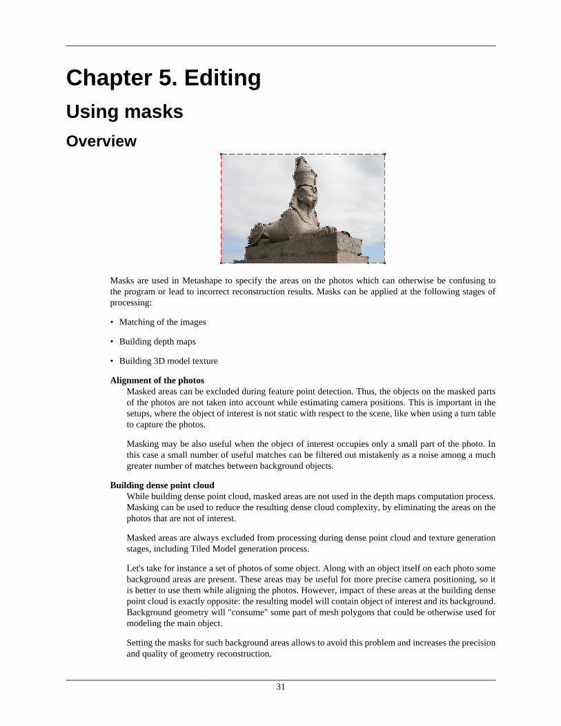
31
Chapter 5. EditingUsing masks
Overview
Masks are used in Metashape to specify the areas on the photos which can otherwise be confusing tothe program or lead to incorrect reconstruction results. Masks can be applied at the following stages ofprocessing:
• Matching of the images
• Building depth maps
• Building 3D model texture
Alignment of the photosMasked areas can be excluded during feature point detection. Thus, the objects on the masked partsof the photos are not taken into account while estimating camera positions. This is important in thesetups, where the object of interest is not static with respect to the scene, like when using a turn tableto capture the photos.
Masking may be also useful when the object of interest occupies only a small part of the photo. Inthis case a small number of useful matches can be filtered out mistakenly as a noise among a muchgreater number of matches between background objects.
Building dense point cloudWhile building dense point cloud, masked areas are not used in the depth maps computation process.Masking can be used to reduce the resulting dense cloud complexity, by eliminating the areas on thephotos that are not of interest.
Masked areas are always excluded from processing during dense point cloud and texture generationstages, including Tiled Model generation process.
Let's take for instance a set of photos of some object. Along with an object itself on each photo somebackground areas are present. These areas may be useful for more precise camera positioning, so itis better to use them while aligning the photos. However, impact of these areas at the building densepoint cloud is exactly opposite: the resulting model will contain object of interest and its background.Background geometry will "consume" some part of mesh polygons that could be otherwise used formodeling the main object.
Setting the masks for such background areas allows to avoid this problem and increases the precisionand quality of geometry reconstruction.
Editing
32
Building texture atlasDuring texture atlas generation (for single mesh model and tiled model), masked areas on the photosare not used for texturing. Masking areas on the photos that are occluded by outliers or obstacles helpsto prevent the "ghosting" effect on the resulting texture atlas.
Loading masksMasks can be loaded from external sources, as well as generated automatically from background imagesif such data is available. Metashape supports loading masks from the following sources:
• From alpha channel of the source photos.
• From separate images.
• Generated from background photos based on background differencing technique.
• Based on reconstructed 3D model.
To import masks
1. Select Import Masks... command from the File menu.
2. In the Import Mask dialog select suitable parameters. Click OK button when done.
3. When generating masks from separate or background images, the folder selection dialog will appear.Browse to the folder containing corresponding images and select it.
4. The progress dialog box will appear displaying the current processing status. To cancel processingclick Cancel button.
The following parameters can be specified during mask import:
MethodSpecifies the source of the mask data.
From Alpha - load masks from alpha channel of the source photos.
From File - load masks from separate images.
From Background - generate masks from background photos.
From Model - generate masks based on reconstructed model.
OperationSpecifies the action to be done in case a second mask is imported for the photo.
Replacement - new mask will be loaded and stored instead of the original one.
Union - two masks will be united and stored.
Intersection - the intersection of the two masks will be stored as a new mask for the photo.
Difference - only the difference between two masks will be stored as a new mask for the photo.
Filename template (not used in From alpha mode)Specifies the file name template used to generate mask file names. This template can contain specialtokens, that will be substituted by corresponding data for each photo being processed. The followingtokens are supported:

Editing
33
{filename} - file name of the source photo without extension.
{fileext} - extension of the source photo.
{camera} - camera label.
{filenum} - sequential number of the mask being imported.
For example, {filename}_mask.png template can be used if masks are available in PNG format andhave a _mask suffix.
Tolerance (From Background method only)Specifies the tolerance threshold used for background differencing. Tolerance value should be setaccording to the color separation between foreground and background pixels. For larger separationhigher tolerance values can be used.
Apply toSpecifies whether masks should be imported for the currently opened photo, active chunk or entireWorkspace.
All cameras - load masks for active chunk.
Entire workspace - load masks for all chunks in the project.
Selected cameras - load mask for the currently checked cameras (if any).
Current photo - load mask for the currently opened photo (if any).
Editing masksModification of the current mask is performed by adding or subtracting selections. A selection is createdwith one of the supported selection tools and is not incorporated in the current mask until it is merged witha mask using Add Selection or Subtract Selection operations.
To edit the mask
1. Open the photo to be masked by double clicking on its name on the Workspace / Photo pane. Thephoto will be opened in the main window. The existing mask will be displayed as a shaded regionon the photo.
2. Select the desired selection tool and generate a selection.
3.Click on Add Selection toolbar button to add current selection to the mask, or Subtract
Selection to subtract the selection from the mask. Invert Selection button allows to invert currentselection prior to adding or subtracting it from the mask.
The following tools can be used for creating selections:
Rectangle selection toolRectangle selection tool is used to select large areas or to clean up the mask after other selection toolswere applied.
Intelligent scissors toolIntelligent scissors is used to generate a selection by specifying its boundary. The boundary is formedby selecting a sequence of vertices with a mouse, which are automatically connected with segments.The segments can be formed either by straight lines, or by curved contours snapped to the object

Editing
34
boundaries. To enable snapping, hold Ctrl key while selecting the next vertex. To complete theselection, the boundary should be closed by clicking on the first boundary vertex.
Intelligent paint toolIntelligent paint tool is used to "paint" a selection by the mouse, continuously adding small imageregions, bounded by object boundaries.
Magic wand toolMagic Wand tool is used to select uniform areas of the image. To make a selection with a MagicWand tool, click inside the region to be selected.
The range of pixel colors selected by Magic Wand is controlled by the tolerance value. At lowertolerance values the tool selects fewer colors similar to the pixel you click with the Magic Wand tool.Higher value broadens the range of colors selected.
Note
• To add new area to the current selection hold the Ctrl key during selection of additional area.
• To reset mask selection on the current photo press Esc key.
A mask can be inverted using Invert Mask command from the Edit menu. The command is active in PhotoView only. Alternatively, you can invert masks either for selected cameras or for all cameras in a chunkusing Invert Masks... command from a photo context menu on the Photos pane.
The masks are generated individually for each image. If some object should be masked out, it should bemasked out on all photos, where that object appears.
Saving masksCreated masks can be also saved for external editing or storage.
To export masks
1. Select Export Masks... command from the File menu.
2. In the Export Mask dialog select suitable parameters. Click OK button when done.
3. Browse to the folder where the masks should be saved and select it.
4. The progress dialog box will appear displaying the current processing status. To cancel processingclick Cancel button.
The following parameters can be specified during mask export:
Export masks forSpecifies whether masks should be exported for the currently opened photo, active chunk or entireWorkspace.
Current photo - save mask for the currently opened photo (if any).
Active chunk - save masks for active chunk.
Entire workspace - save masks for all chunks in the project.
File typeSpecifies the type of generated files.

Editing
35
Single channel mask image - generates single channel black and white mask images.
Image with alpha channel - generates color images from source photos combined with maskdata in alpha channel.
Mask file namesSpecifies the file name template used to generate mask file names. This template can contain specialtokens, that will be substituted by corresponding data for each photo being processed. The followingtokens are supported:
{filename} - file name of the source photo without extension.
{fileext} - extension of the source photo.
{camera} - camera label.
{filenum} - sequential number of the mask being exported.
For example, {filename}_mask.png template can be used to export masks in PNG format with _masksuffix.
Note
• When importing/exporting mask for the current photo only, Metashape will prompt for the actualimage instead of image folder. Mask file names parameter will not be used in this case.
Editing point cloudThe following point cloud editing tools are available in Metashape:
• Automatic filtering based on specified criterion (sparse cloud only)
• Automatic filtering based on applied masks (dense cloud only)
• Automatic filtering based on points colors (dense cloud only)
• Reducing number of points in cloud by setting tie point per photo limit (sparse cloud only)
• Manual points removal
Note
• Point cloud editing operation can be undone/redone using Undo/Redo command from the Editmenu.
Filtering points based on specified criterionIn some cases it may be useful to find out where the points with high reprojection error are located withinthe sparse cloud, or remove points representing high amount of noise. Point cloud filtering helps to selectsuch points, which usually are supposed to be removed.
Metashape supports the following criteria for point cloud filtering:
Reprojection errorHigh reprojection error usually indicates poor localization accuracy of the corresponding pointprojections at the point matching step. It is also typical for false matches. Removing such points canimprove accuracy of the subsequent optimization step.
Editing
36
Reconstruction uncertaintyHigh reconstruction uncertainty is typical for points, reconstructed from nearby photos with smallbaseline. Such points can noticeably deviate from the object surface, introducing noise in the pointcloud. While removal of such points should not affect the accuracy of optimization, it may be usefulto remove them before building geometry in Point Cloud mode or for better visual appearance of thepoint cloud.
Image countMetashape reconstruct all the points that are visible at least on two photos. However, points that arevisible only on two photos are likely to be located with poor accuracy. Image count filtering enablesto remove such unreliable points from the cloud.
Projection AccuracyThis criterion allows to filter out points which projections were relatively poorer localized due to theirbigger size.
To remove points based on specified criterion
1.Switch to Point Cloud view mode using Point Cloud toolbar button.
2. Select Gradual Selection... command from the Model menu.
3. In the Gradual Selection dialog box specify the criterion to be used for filtering. Adjust the thresholdlevel using the slider. You can observe how the selection changes while dragging the slider. ClickOK button to finalize the selection.
4.To remove selected points use Delete Selection command from the Edit menu or click DeleteSelection toolbar button (or simply press Del button on the keyboard).
Filtering points based on applied masks
To remove points based on applied masks
1.Switch to Dense Cloud view mode using Dense Cloud toolbar button.
2. Choose Select Masked Points... command from the Dense Cloud submenu of the Tools menu.
3. In the Select Masked Points dialog box indicate the photos whose masks to be taken into account.Adjust the edge softness level using the slider. Click OK button to run the selection procedure.
4.To remove selected points use Delete Selection command from the Edit menu or click DeleteSelection toolbar button (or simply press Del button on the keyboard).
Filtering points based on points colors
To remove points based on points colors
1.Switch to Dense Cloud view mode using Dense Cloud toolbar button.
2. Choose Select Points by Color... command from the Dense Cloud submenu of the Tools menu.
3. In the Select Points by Color dialog box the color to be used as the criterion. Adjust the tolerancelevel using the slider. Click OK button to run the selection procedure.
Editing
37
4.To remove selected points use Delete Selection command from the Edit menu or click DeleteSelection toolbar button (or simply press Del button on the keyboard).
Tie point per photo limitTie point limit parameter could be adjusted before Align photos procedure. The number indicates the upperlimit for matching points for every image. Using zero value doesn't apply any tie-point filtering.
The number of tie points can also be reduced after the alignment process with Tie Points - Thin Point Cloudcommand available from Tools menu. As a results sparse point cloud will be thinned, yet the alignmentwill be kept unchanged.
Manual points removalIncorrect points can be also removed manually.
To remove points from a point cloud manually
1.Switch to Sparse Cloud view mode using Point Cloud toolbar button or to Dense Cloud view
mode using Dense Cloud toolbar button.
2.Select points to be removed using Rectangle Selection, Circle Selection or Free-FormSelection tools. To add new points to the current selection hold the Ctrl key during selection ofadditional points. To remove some points from the current selection hold the Shift key duringselection of points to be removed.
3.To delete selected points click the Delete Selection toolbar button or select Delete Selection
command from the Edit menu. To crop selection to the selected points click the Crop Selectiontoolbar button or select Crop Selection command from the Edit menu.
Editing model geometryThe following mesh editing tools are available in Metashape:
• Decimation tool
• Close Holes tool
• Smooth tool
• Automatic filtering based on specified criterion
• Manual polygon removal
• Fixing mesh topology
• Refinement tool
More complex editing can be done in the external 3D editing tools. Metashape allows to export mesh andthen import it back for this purpose.

Editing
38
Note
• For polygon removal operations such as manual removal and connected component filtering itis possible to undo the last mesh editing operation. There are Undo/Redo commands in the Editmenu.
• Please note that undo/redo commands are not supported for mesh decimation and this operationcannot be undone.
Decimation toolDecimation is a tool used to decrease the geometric resolution of the model by replacing high resolutionmesh with a lower resolution one, which is still capable of representing the object geometry with highaccuracy. Metashape tends to produce 3D models with excessive geometry resolution, so mesh decimationis usually a desirable step after geometry computation.
Highly detailed models may contain hundreds of thousands polygons. While it is acceptable to work withsuch a complex models in 3D editor tools, in most conventional tools like Adobe Reader or Google Earthhigh complexity of 3D models may noticeably decrease application performance. High complexity alsoresults in longer time required to build texture and to export model in pdf file format.
In some cases it is desirable to keep as much geometry details as possible like it is needed for scientific andarchive purposes. However, if there are no special requirements it is recommended to decimate the modeldown to 100 000 - 200 000 polygons for exporting in PDF, and to 100 000 or even less for displaying inGoogle Earth and alike tools.
To decimate 3D model
1. Select Decimate Mesh... command from the Tools menu.
2. In the Decimate Mesh dialog box specify the target number of polygons, which should remain in thefinal model. Click on the OK button to start decimation.
3. The progress dialog box will appear displaying the current processing status. To cancel processingclick on the Cancel button.
Note
• Texture atlas is discarded during decimation process. You will have to rebuild texture atlas afterdecimation is complete.
Close Holes toolClose Holes tool provides possibility to repair your model if the reconstruction procedure resulted in amesh with several holes, due to insufficient image overlap for example.
Close holes tool enables to close void areas on the model substituting photogrammetric reconstructionwith extrapolation data. It is possible to control an acceptable level of accuracy indicating the maximumsize of a hole to be covered with extrapolated data.
To close holes in a 3D model
1. Select Close Holes... command from the Tools menu.
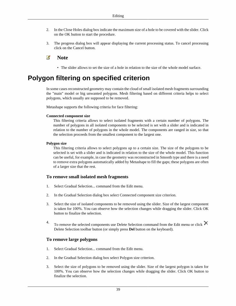
Editing
39
2. In the Close Holes dialog box indicate the maximum size of a hole to be covered with the slider. Clickon the OK button to start the procedure.
3. The progress dialog box will appear displaying the current processing status. To cancel processingclick on the Cancel button.
Note
• The slider allows to set the size of a hole in relation to the size of the whole model surface.
Polygon filtering on specified criterionIn some cases reconstructed geometry may contain the cloud of small isolated mesh fragments surroundingthe "main" model or big unwanted polygons. Mesh filtering based on different criteria helps to selectpolygons, which usually are supposed to be removed.
Metashape supports the following criteria for face filtering:
Connected component sizeThis filtering criteria allows to select isolated fragments with a certain number of polygons. Thenumber of polygons in all isolated components to be selected is set with a slider and is indicated inrelation to the number of polygons in the whole model. The components are ranged in size, so thatthe selection proceeds from the smallest component to the largest one.
Polygon sizeThis filtering criteria allows to select polygons up to a certain size. The size of the polygons to beselected is set with a slider and is indicated in relation to the size of the whole model. This functioncan be useful, for example, in case the geometry was reconstructed in Smooth type and there is a needto remove extra polygons automatically added by Metashape to fill the gaps; these polygons are oftenof a larger size that the rest.
To remove small isolated mesh fragments
1. Select Gradual Selection... command from the Edit menu.
2. In the Gradual Selection dialog box select Connected component size criterion.
3. Select the size of isolated components to be removed using the slider. Size of the largest componentis taken for 100%. You can observe how the selection changes while dragging the slider. Click OKbutton to finalize the selection.
4.To remove the selected components use Delete Selection command from the Edit menu or click Delete Selection toolbar button (or simply press Del button on the keyboard).
To remove large polygons
1. Select Gradual Selection... command from the Edit menu.
2. In the Gradual Selection dialog box select Polygon size criterion.
3. Select the size of polygons to be removed using the slider. Size of the largest polygon is taken for100%. You can observe how the selection changes while dragging the slider. Click OK button tofinalize the selection.

Editing
40
4.To remove the selected components use Delete Selection command from the Edit menu or click Delete Selection toolbar button (or simply press Del button on the keyboard).
Note that Metashape always selects the fragments starting from the smallest ones. If the model containsonly one component the selection will be empty.
Manual face removalUnnecessary and excessive sections of model geometry can be also removed manually.
To remove part of the mesh polygons manually
1.Select rectangle, circle or free-form selection tool using Rectangle Selection, Circle Selection
or Free-Form Selection toolbar buttons.
2. Make the selection using the mouse. To add new polygons to the current selection hold the Ctrl keyduring selection of additional polygons. To remove some polygons from the current selection holdthe Shift key during selection of polygons to be excluded.
3.To delete selected polygons click the Delete Selection toolbar button or use Delete Selection
command from the Edit menu. To crop selection to the selected polygons click the Crop Selectiontoolbar button or use Crop Selection command from the Edit menu.
To grow or shrink current selection
1. To grow current selection press PageUp key in the selection mode. To grow selection by even a largeramount, press PageUp while holding Shift key pressed.
2. To shrink current selection press PageDown key in the selection mode. To shrink selection by evena larger amount, press PageDown while holding Shift key pressed.
Fixing mesh topologyMetashape is capable of basic mesh topology fixing.
To fix mesh topology
1. Select View Mesh Statistics... command from the Tools menu.
2. In the Mesh Statistics dialog box you can inspect mesh parameters. If there are any topologicalproblems, Fix Topology button will be active and can be clicked to solve the problems.
3. The progress dialog box will appear displaying the current processing status. To cancel processingclick on the Cancel button.
Editing mesh in the external program
To export mesh for editing in the external program
1. Select Export Model... command from the File menu.

Editing
41
2. In the Save As dialog box, specify the desired mesh format in the Save as type combo box. Select thefile name to be used for the model and click Save button.
3. In the opened dialog box specify additional parameters specific to the selected file format. Click OKbutton when done.
To import edited mesh
1. Select Import Mesh... command from the File menu.
2. In the Open dialog box, browse to the file with the edited model and click Open.
Note
• Metashape supports loading models in Wavefront OBJ, 3DS, STL, COLLADA, Stanford PLY,Autodesk FBX, Autodesk DXF, OpenCTM and U3D file formats only. Please make sure to selectone of these file formats when exporting model from the external 3D editor.
•

42
Chapter 6. AutomationUsing chunks
When working with typical data sets, automation of general processing workflow allows to perform routineoperations efficiently. Metashape allows to assign several processing steps to be run one by one withoutuser intervention thanks to Batch Processing feature. Manual user intervention can be minimized evenfurther due to 'multiple chunk project' concept, each chunk to include one typical data set. For a project withseveral chunks of the same nature, common operations available in Batch Processing dialog are applied toeach selected chunk individually, thus allowing to set several data sets for automatic processing followingpredefined workflow pattern.
In addition, multiple chunk project could be useful when it turns out to be hard or even impossible togenerate a 3D model of the whole scene in one go. This could happen, for instance, if the total amountof photographs is too large to be processed at a time. To overcome this difficulty Metashape offers apossibility to split the set of photos into several separate chunks within the same project. Alignment ofphotos, building dense point cloud, building mesh, and forming texture atlas operations can be performedfor each chunk separately and then resulting 3D models can be combined together.
Working with chunks is not more difficult than using Metashape following the general workflow. In fact,in Metashape always exists at least one active chunk and all the 3D model processing workflow operationsare applied to this chunk.
To work with several chunks you need to know how to create chunks and how to combine resulting 3Dmodels from separate chunks into one model.
Creating a chunk
To create new chunk click on the Add Chunk toolbar button on the Workspace pane or select AddChunk command from the Workspace context menu (available by right-clicking on the root element onthe Workspace pane).
After the chunk is created you may load photos in it, align them, generate dense point cloud, generate meshsurface model, build texture atlas, export the models at any stage and so on. The models in the chunksare not linked with each other.
The list of all the chunks created in the current project is displayed in the Workspace pane along withflags reflecting their status.
The following flags can appear next to the chunk name:
R (Referenced)Will appear when two or more chunks are aligned with each other.
To move photos from one chunk to another simply select them in the list of photos on the Workspace pane,and then drag and drop to the target chunk.
Working with chunksAll operations within the chunk are carried out following the common workflow: loading photographs,aligning them, generating dense point cloud, building mesh, building texture atlas, exporting 3D modeland so on.
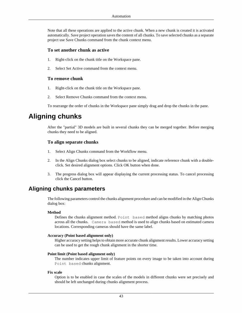
Automation
43
Note that all these operations are applied to the active chunk. When a new chunk is created it is activatedautomatically. Save project operation saves the content of all chunks. To save selected chunks as a separateproject use Save Chunks command from the chunk context menu.
To set another chunk as active
1. Right-click on the chunk title on the Workspace pane.
2. Select Set Active command from the context menu.
To remove chunk
1. Right-click on the chunk title on the Workspace pane.
2. Select Remove Chunks command from the context menu.
To rearrange the order of chunks in the Workspace pane simply drag and drop the chunks in the pane.
Aligning chunksAfter the "partial" 3D models are built in several chunks they can be merged together. Before mergingchunks they need to be aligned.
To align separate chunks
1. Select Align Chunks command from the Workflow menu.
2. In the Align Chunks dialog box select chunks to be aligned, indicate reference chunk with a double-click. Set desired alignment options. Click OK button when done.
3. The progress dialog box will appear displaying the current processing status. To cancel processingclick the Cancel button.
Aligning chunks parameters
The following parameters control the chunks alignment procedure and can be modified in the Align Chunksdialog box:
MethodDefines the chunks alignment method. Point based method aligns chunks by matching photosacross all the chunks. Camera based method is used to align chunks based on estimated cameralocations. Corresponding cameras should have the same label.
Accuracy (Point based alignment only)Higher accuracy setting helps to obtain more accurate chunk alignment results. Lower accuracy settingcan be used to get the rough chunk alignment in the shorter time.
Point limit (Point based alignment only)The number indicates upper limit of feature points on every image to be taken into account duringPoint based chunks alignment.
Fix scaleOption is to be enabled in case the scales of the models in different chunks were set precisely andshould be left unchanged during chunks alignment process.

Automation
44
Preselect image pairs (Point based alignment only)The alignment process of many chunks may take a long time. A significant portion of this time isspent for matching of detected features across the photos. Image pair preselection option can speedup this process by selection of a subset of image pairs to be matched.
Constrain features by mask (Point based alignment only)When this option is enabled, features detected in the masked image regions are discarded. Foradditional information on the usage of masks refer to the Using masks section.
Note
• Chunk alignment can be performed only for chunks containing aligned photos.
Merging chunksAfter alignment is complete the separate chunks can be merged into a single chunk.
To merge chunks
1. Select Merge Chunks command from the Workflow menu.
2. In the Merge Chunks dialog box select chunks to be merged and the desired merging options. ClickOK button when done.
3. Metashape will merge the separate chunks into one. The merged chunk will be displayed in the projectcontent list on Workspace pane.
The following parameters control the chunks merging procedure and can be modified in the Merge Chunksdialog box:
Merge tie pointsDefines if the projections of the tie points for corresponding features should be merged. Since tiepoints merging operation assumes re-matching of the features from different chunks, the operationmay be time consuming. Thus it is recommended to disable tie points merging, unless it is requiredby the task specifics.
Merge dense cloudsDefines if dense clouds from the selected chunks are combined.
Merge modelsDefines if models from the selected chunks are combined.
Chunks merging result (i.e. photos, point clouds and geometry) will be stored in the new chunk and it maybe treated as an ordinary chunk (e.g. the model can be textured and/or exported).
Note
• Dense cloud and model merging operations will be applied only to the active items. Disabled(inactive) items will not be transfered to the merged chunk.
Batch processingMetashape allows to perform general workflow operations with multiple chunks automatically. It is usefulwhen dealing with a large number of chunks to be processed.

Automation
45
Batch processing can be applied to all chunks in the Workspace, to unprocessed chunks only, or to thechunks selected by the user. Each operation chosen in the Batch processing dialog will be applied to everyselected chunk before processing will move on to the next step.
Align Photos Align/Merge Chunks Save/Load Project
Optimize Alignment Decimate Mesh Export/Import Cameras
Build Dense Cloud Smooth Model Export Points
Build Mesh Close Holes Export Model
Build Texture Calibrate Colors Export Texture
Refine Mesh Import Masks Reset Region
Generate Report Undistort Photos
To start batch processing
1. Select Batch Process... command from the Workflow menu.
2. Click Add to add the desired processing stages.
3. In the Add Job dialog select the kind of operation to be performed, the list of chunks it should beapplied to, and desired processing parameters. Click OK button when done.
4. Repeat the previous steps to add other processing steps as required.
5. Arrange jobs by clicking Up and Down arrows at the right of the Batch Process... dialog box.
6. Click OK button to start processing.
7. The progress dialog box will appear displaying the list and status of batch jobs and current operationprogress. To cancel processing click the Cancel button.
When the batch process includes import/export features that are applied to multiple chunks it is reasonableto use the following templates in the Path field of the import/export jobs:
• {filename} - filename (without extension),
• {fileext} - file extension,
• {camera} - camera label,
• {frame} - frame index,
• {chunklabel} - chunk label,
• {imagefolder} - folder containing images of an active chunk,
• {projectfolder} - path to the folder containing current project,
• {projectname} - current project filename,
• {projectpath} - absolute path to the current project.
The list of tasks for batch processing can be exported to XML structured file using Save button in the
Batch processing dialog and imported in a different project using Open button.

46
Chapter 7. Distributed processing
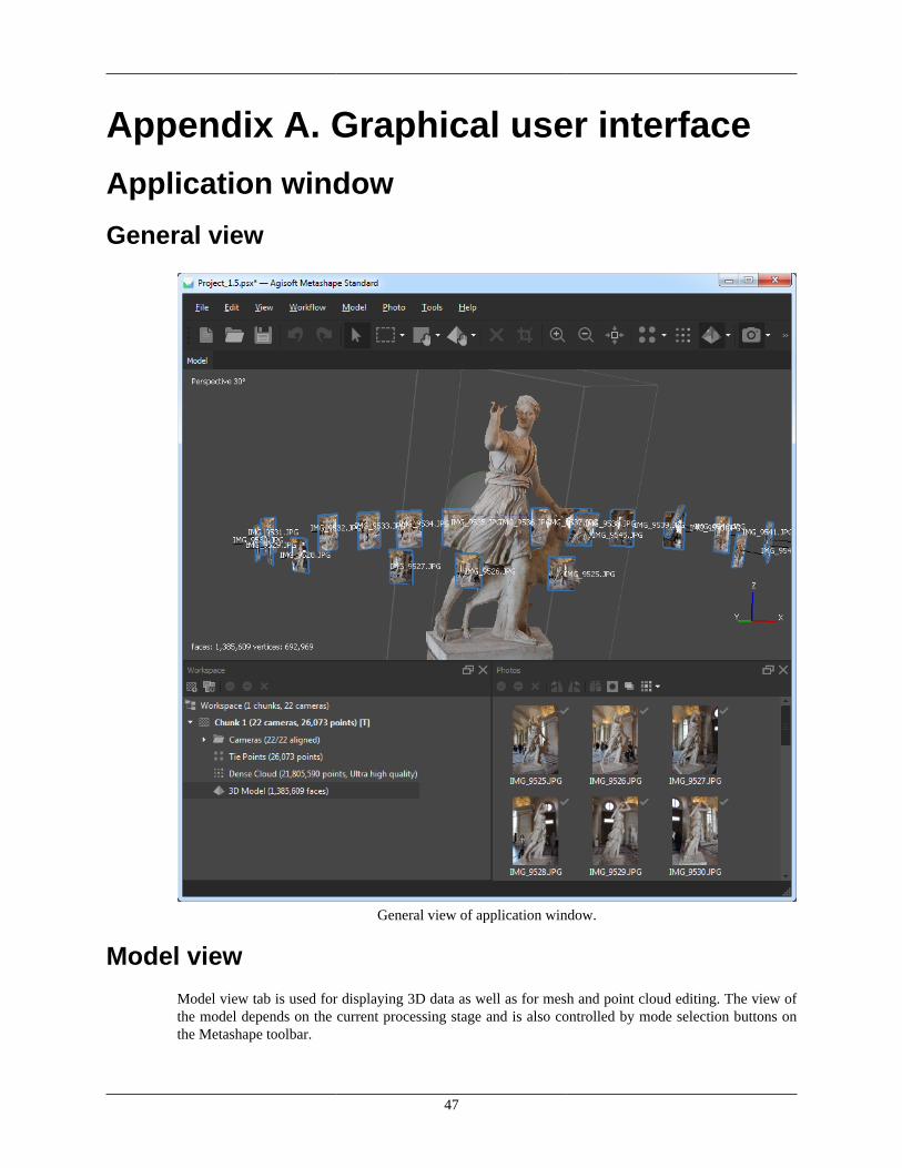
47
Appendix A. Graphical user interface
Application window
General view
General view of application window.
Model view
Model view tab is used for displaying 3D data as well as for mesh and point cloud editing. The view ofthe model depends on the current processing stage and is also controlled by mode selection buttons onthe Metashape toolbar.
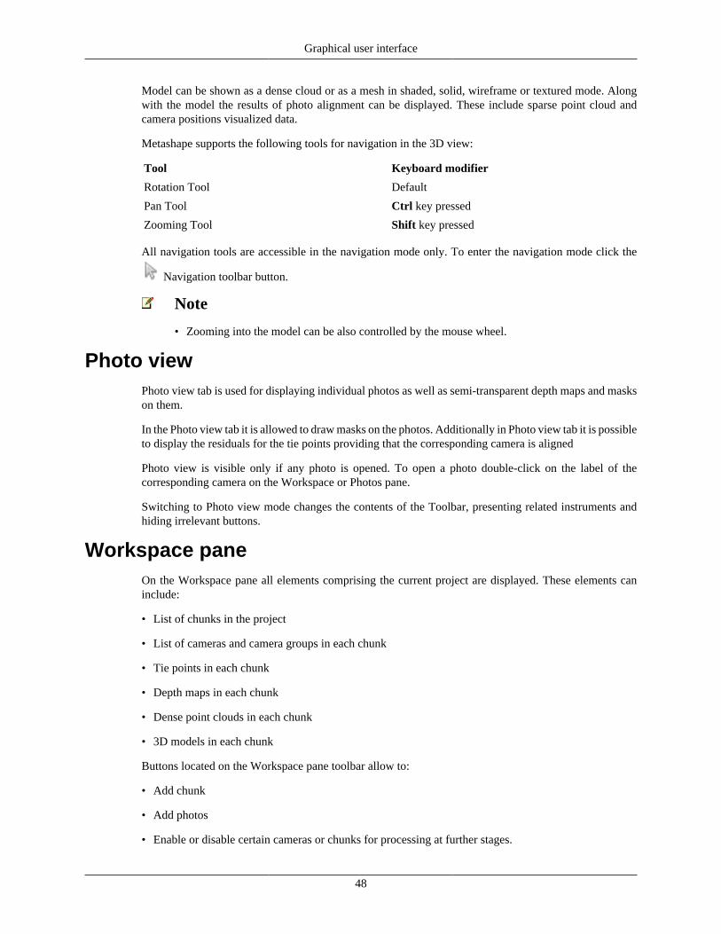
Graphical user interface
48
Model can be shown as a dense cloud or as a mesh in shaded, solid, wireframe or textured mode. Alongwith the model the results of photo alignment can be displayed. These include sparse point cloud andcamera positions visualized data.
Metashape supports the following tools for navigation in the 3D view:
Tool Keyboard modifier
Rotation Tool Default
Pan Tool Ctrl key pressed
Zooming Tool Shift key pressed
All navigation tools are accessible in the navigation mode only. To enter the navigation mode click the
Navigation toolbar button.
Note
• Zooming into the model can be also controlled by the mouse wheel.
Photo viewPhoto view tab is used for displaying individual photos as well as semi-transparent depth maps and maskson them.
In the Photo view tab it is allowed to draw masks on the photos. Additionally in Photo view tab it is possibleto display the residuals for the tie points providing that the corresponding camera is aligned
Photo view is visible only if any photo is opened. To open a photo double-click on the label of thecorresponding camera on the Workspace or Photos pane.
Switching to Photo view mode changes the contents of the Toolbar, presenting related instruments andhiding irrelevant buttons.
Workspace paneOn the Workspace pane all elements comprising the current project are displayed. These elements caninclude:
• List of chunks in the project
• List of cameras and camera groups in each chunk
• Tie points in each chunk
• Depth maps in each chunk
• Dense point clouds in each chunk
• 3D models in each chunk
Buttons located on the Workspace pane toolbar allow to:
• Add chunk
• Add photos
• Enable or disable certain cameras or chunks for processing at further stages.

Graphical user interface
49
• Remove items
Each element in the list is linked with the context menu providing quick access to some commonoperations.
Photos panePhotos pane displays the list of photos / masks / depth maps in the active chunk in the form of thumbnails.
Buttons located on the Photos pane toolbar allow to:
• Enable / disable certain cameras
• Remove cameras
• Rotate selected photos clockwise / counterclockwise (for display purposes only)
• Reset current photo filtering option
• Switch between images / masks / depth maps thumbnails
• Increase / decrease icons' size or display detailed information on photos including EXIF data
Console paneConsole pane is used for:
• Displaying auxiliary information
• Displaying error messages
Buttons located on the pane toolbar allow:
• Save log (in HTML, XHTML or Plain Text format)
• Clear log
Jobs paneJobs pane is designed for:
• Monitoring the processing status for active and background projects
• Organizing the background processing queue
• Switching between the projects
Buttons located on the pane toolbar allow:
• Start / pause / cancel the selected tasks
• Change the order of the tasks in the processing queue
• Clear the processing tasks history
Animation paneAnimation pane is designed for:
• Loading the camera track

Graphical user interface
50
• Start / stop the camera movement according to the track
• Render the frame sequence to the form of the video file
Buttons located on the pane toolbar allow:
• Start / stop the animation according to the camera track
• Render the animation and save to the external video file
• Create track, load track and adjust track properties through Settings dialog
Note
• To open any pane select a corresponding command from the View menu.
Menu commandsFile Menu
NewCreates an empty Metashape project.
Open...Opens Metashape project file.
Append...Appends existing Metashape project file to thecurrent one.
SaveSaves Metashape project file.
Save As...Saves Metashape project file with a new name.
Export Points...Saves sparse / dense point cloud.
Export Model...Saves 3D model.
Export Cameras...Exports camera positions, orientation data and tiepoints measurements.
Export Masks...Exports masks.
Export Texture...Exports model texture.
Export Panorama...Exports spherical panorama for camera stations.
Undistort Photos...Removes nonlinear distortions by warping sourcephotos and saving the result as files.
Render Photos...Lenticular images generation
Import Cameras...Imports camera positions and orientation data.
Import Masks...Imports masks or creates mask from model orbackground.
Import Points...Imports points in a form of the dense point cloud.
Import Model...Imports polygonal mesh model.
Import Texture...Imports texture and applies it to the current model.

Graphical user interface
51
File Menu
Import Video...Imports video in a form of frame sequence andsaves the extracted frames as images.
Upload Data...Uploads generated products (points, textured meshmodels ) to one of the supported web-sites.
ExitCloses the application window.
Edit Menu
UndoUndo the last editing operation.
RedoRedo the previously undone editing operation.
Add selectionAdds current selection to the mask.
Subtract selectionSubtracts current selection from the mask.
Invert SelectionInverts current selection for the photo.
Invert SelectionInverts current selection of faces / points / cameras.
Grow SelectionGrows current selection of mesh faces.
Shrink SelectionShrinks current selection of mesh faces.
Delete SelectionRemoves selected faces from the mesh or selectedpoints from the point cloud.
Crop SelectionCrops selected faces / points.
Invert MaskInverts mask for the current photo.
Reset maskResets mask for the current photo.
Rotate rightRotates the photo clockwise.
Rotate leftRotates the photo counterclockwise.
View Menu
Zoom InIncreases magnification in the active view mode.
Zoom OutDecreases magnification in the active view mode.
Reset ViewResets the viewport to display the complete modelor photo.
Capture viewSaves screenshot of current view of the project(Model/Ortho/Photo)
WorkspaceShows or hides Workspace pane.
AnimationShows or hides Animation pane.
PhotosShows or hides Photos pane.
ConsoleShows or hides Console pane.
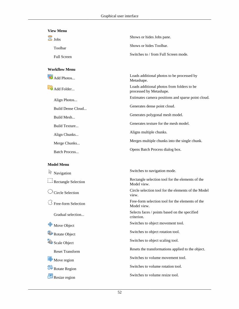
Graphical user interface
52
View Menu
JobsShows or hides Jobs pane.
ToolbarShows or hides Toolbar.
Full ScreenSwitches to / from Full Screen mode.
Workflow Menu
Add Photos...Loads additional photos to be processed byMetashape.
Add Folder...Loads additional photos from folders to beprocessed by Metashape.
Align Photos...Estimates camera positions and sparse point cloud.
Build Dense Cloud...Generates dense point cloud.
Build Mesh...Generates polygonal mesh model.
Build Texture...Generates texture for the mesh model.
Align Chunks...Aligns multiple chunks.
Merge Chunks...Merges multiple chunks into the single chunk.
Batch Process...Opens Batch Process dialog box.
Model Menu
NavigationSwitches to navigation mode.
Rectangle SelectionRectangle selection tool for the elements of theModel view.
Circle SelectionCircle selection tool for the elements of the Modelview.
Free-form SelectionFree-form selection tool for the elements of theModel view.
Gradual selection...Selects faces / points based on the specifiedcriterion.
Move ObjectSwitches to object movement tool.
Rotate ObjectSwitches to object rotation tool.
Scale ObjectSwitches to object scaling tool.
Reset TransformResets the transformations applied to the object.
Move regionSwitches to volume movement tool.
Rotate RegionSwitches to volume rotation tool.
Resize regionSwitches to volume resize tool.
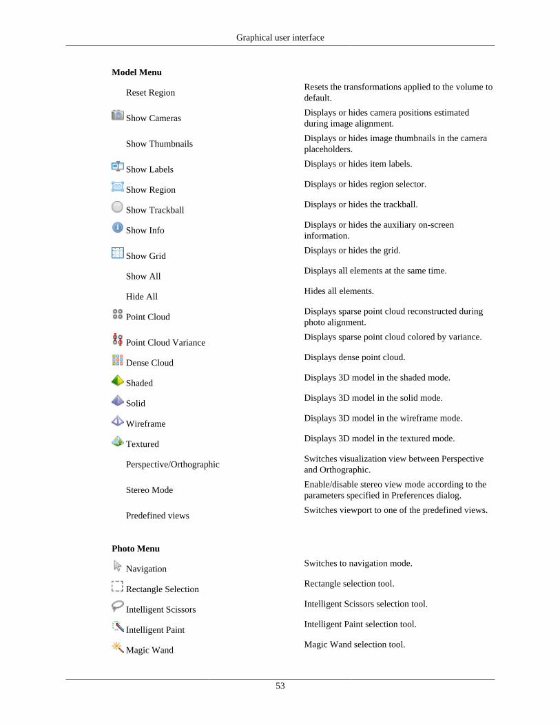
Graphical user interface
53
Model Menu
Reset RegionResets the transformations applied to the volume todefault.
Show CamerasDisplays or hides camera positions estimatedduring image alignment.
Show ThumbnailsDisplays or hides image thumbnails in the cameraplaceholders.
Show LabelsDisplays or hides item labels.
Show RegionDisplays or hides region selector.
Show TrackballDisplays or hides the trackball.
Show InfoDisplays or hides the auxiliary on-screeninformation.
Show GridDisplays or hides the grid.
Show AllDisplays all elements at the same time.
Hide AllHides all elements.
Point CloudDisplays sparse point cloud reconstructed duringphoto alignment.
Point Cloud VarianceDisplays sparse point cloud colored by variance.
Dense CloudDisplays dense point cloud.
ShadedDisplays 3D model in the shaded mode.
SolidDisplays 3D model in the solid mode.
WireframeDisplays 3D model in the wireframe mode.
TexturedDisplays 3D model in the textured mode.
Perspective/OrthographicSwitches visualization view between Perspectiveand Orthographic.
Stereo ModeEnable/disable stereo view mode according to theparameters specified in Preferences dialog.
Predefined viewsSwitches viewport to one of the predefined views.
Photo Menu
NavigationSwitches to navigation mode.
Rectangle SelectionRectangle selection tool.
Intelligent ScissorsIntelligent Scissors selection tool.
Intelligent PaintIntelligent Paint selection tool.
Magic WandMagic Wand selection tool.

Graphical user interface
54
Photo Menu
Open Next PhotoOpens next photo from the list in the Photos pane.
Open Previous PhotoOpens previous photo from the list in the Photospane.
Show MasksTurns mask shading on or off.
Show Depth MapsTurns depth maps overlay on or off.
Show LabelsDisplays or hides item labels.
Show PointsDisplays or hides tie point projections used for thecamera alignment.
Show AllDisplays all elements at the same time.
Hide AllHides all elements.
Tools Menu
Build Point Cloud...Builds sparse point cloud based on the estimatedcamera parameters available.
Thin Point Cloud...Thins sparse point cloud by reducing the numberof projections on the individual photos to the givenlimit.
View Matches...Displays View Matches dialog for visualrepresentation of the common tie points betweenthe image pairs.
Invert Point Normals...Inverts normals for the selected points of the densecloud.
Select Points by Masks...Selects dense cloud points according to the masksof the selected images.
Select Points by Color...Selects dense cloud points according to the colorand tolerance.
Filter By SelectionFilters the points in the dense cloud according tothe selected points.
Reset FilterResets all applied dense cloud filters.
Compact Dense Cloud...Permanently removes all deleted points from thedense cloud.
Restore Dense Cloud...Restores all deleted points of the dense cloud thatwere once marked as removed.
Update Dense Cloud...Updates statistics of the dense cloud, includingpoint numbers and assigned classes.
Refine Mesh...Starts photoconsistent mesh refinement operation.
Decimate Mesh...Decimates mesh to the target face count.
Smooth Mesh...Smoothes mesh.
Close Holes...Closes holes on the model surface.

Graphical user interface
55
Tools Menu
View Mesh Statistics...Collects and displays mesh statistics.
View Mesh UVs...Displays mesh UV mapping.
Filter By SelectionFilters the faces of the polygonal model accordingto the selected points.
Reset FilterResets all applied mesh filters.
Calibrate Lens...Displays lens calibration dialog.
Show Chessboard...Displays the calibration board on screen.
Camera Calibration...Displays camera calibration dialog box.
Optimize Cameras...Starts the optimization of exterior and interiorparameters of the aligned cameras.
Calibrate Colors...Displays the color correction dialog for thebrightness and white balance compensation of theimages.
Set Primary Channel...Displays the primary channel selection dialog.
Set Brightness...Adjusts image brightness and contrast for moreconvenient display.
Preferences...Displays preferences dialog box.
Help Menu
ContentsDisplays help contents.
Check for Updates...Checks if Metashape update is available fordownload.
Activate Product...Displays the activation dialog for activation /deactivation of the product using the activationkey .
About Metashape...Displays program information, version number andcopyright.
Toolbar buttons
General commands
NewCreates a new Metashape project file.
OpenOpens a Metashape project file.
SaveSaves a Metashape project file.
3D view commands
UndoUndo the last editing operation.

Graphical user interface
56
3D view commands
RedoRedo the previously undone editing operation.
NavigationNavigation tool.
Rectangle SelectionRectangle selection tool.
Circle SelectionCircle selection tool.
Free-Form SelectionFree-form selection tool.
Reset SelectionResets current selection.
Move regionVolume translation tool.
Resize regionVolume resize tool.
Rotate RegionVolume rotation tool.
Reset RegionResets region according to the actual point cloud.
Move ObjectModel translation tool.
Rotate ObjectModel rotation tool.
Scale ObjectModel resize tool.
Reset TransformResets all transformations applied to the model.
Delete SelectionRemoves selected faces / points.
Crop SelectionCrops selected faces / points.
3D view settings
Zoom InIncreases magnification.
Zoom OutDecreases magnification.
Reset ViewResets model view.
Point CloudDisplays sparse point cloud reconstructed duringimage alignment.
Point Cloud VarianceDisplays sparse point cloud colored by variance.
Dense CloudDisplays dense point cloud model.
ShadedDisplays 3D model in the shaded mode.
SolidDisplays 3D model in the solid mode.
WireframeDisplays 3D model in the wireframe mode.
TexturedDisplays 3D model in the textured mode.
Show CamerasDisplays or hides camera positions, reconstructedduring image alignment.
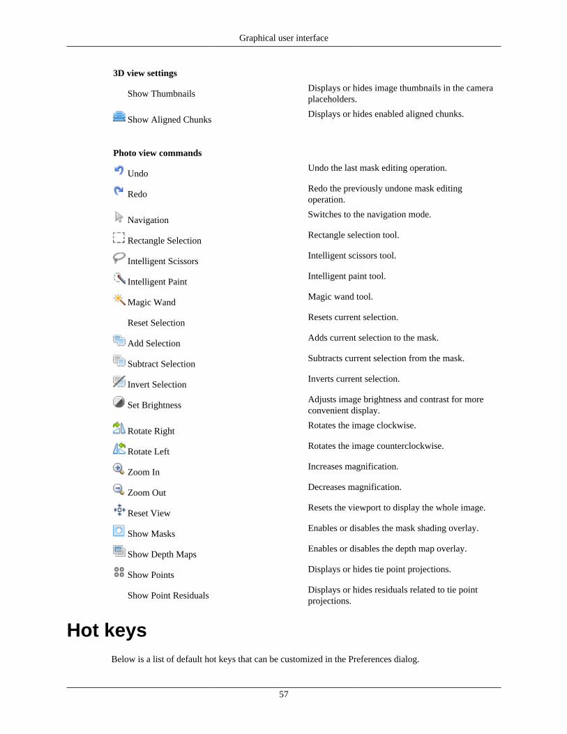
Graphical user interface
57
3D view settings
Show ThumbnailsDisplays or hides image thumbnails in the cameraplaceholders.
Show Aligned ChunksDisplays or hides enabled aligned chunks.
Photo view commands
UndoUndo the last mask editing operation.
RedoRedo the previously undone mask editingoperation.
NavigationSwitches to the navigation mode.
Rectangle SelectionRectangle selection tool.
Intelligent ScissorsIntelligent scissors tool.
Intelligent PaintIntelligent paint tool.
Magic WandMagic wand tool.
Reset SelectionResets current selection.
Add SelectionAdds current selection to the mask.
Subtract SelectionSubtracts current selection from the mask.
Invert SelectionInverts current selection.
Set BrightnessAdjusts image brightness and contrast for moreconvenient display.
Rotate RightRotates the image clockwise.
Rotate LeftRotates the image counterclockwise.
Zoom InIncreases magnification.
Zoom OutDecreases magnification.
Reset ViewResets the viewport to display the whole image.
Show MasksEnables or disables the mask shading overlay.
Show Depth MapsEnables or disables the depth map overlay.
Show PointsDisplays or hides tie point projections.
Show Point ResidualsDisplays or hides residuals related to tie pointprojections.
Hot keysBelow is a list of default hot keys that can be customized in the Preferences dialog.

Graphical user interface
58
General
Create new project Ctrl + N
Save project Ctrl + S
Load project Ctrl + O
Run Script Ctrl + R
Full Screen F11
Model View
Undo (only for Delete, Masking and Close Holesoperations)
Ctrl + Z
Redo (only for Delete, Masking and Close Holesoperations)
Ctrl + Y
Switch between navigation and any otherpreviously selected mode
Space
Reset view 0
Switch to stereoview mode 9
Switch between orthographic and perspective viewmodes
5
Change the angle for perspective view Ctrl + mouse wheel
Predefined Views
Top 7
Bottom Ctrl + 7
Right 3
Left Ctrl + 3
Front 1
Back Ctrl + 1
Rotate View
Rotate Up 8
Rotate Down 2
Rotate Left 4
Rotate Right 6
Photo View
Next photo (according to Photos pane order) Page Up
Previous photo (according to Photos pane order) Page Down
Navigation mode V
Selection Tools
Rectangle selection M
Intelligent scissors L
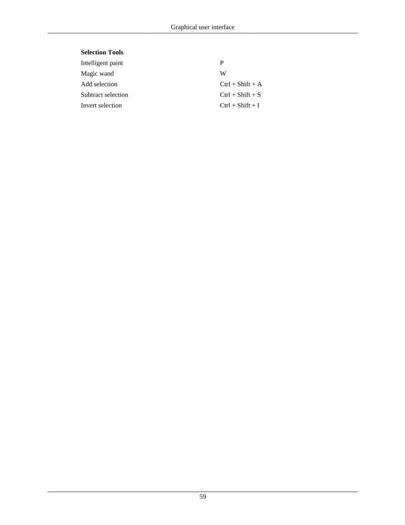
Graphical user interface
59
Selection Tools
Intelligent paint P
Magic wand W
Add selection Ctrl + Shift + A
Subtract selection Ctrl + Shift + S
Invert selection Ctrl + Shift + I

60
Appendix B. Supported formatsImages
Input formats Undistort formats
JPG JPG
TIFF TIFF
PNG PNG
BMP BMP
OpenEXR OpenEXR
JPEG 2000 JPEG 2000
TARGA
Digital Negative (DNG)
Portable Bit Map (PGM, PPM)
Multi-Picture Object (MPO)
Norpix Sequence (SEQ)
AscTec Thermal Images (ARA)
Camera calibrationImport formats Export formats
Agisoft Camera Calibration (*.xml) Agisoft Camera Calibration (*.xml)
Australis Camera Parameters (*.txt) Australis Camera Parameters (*.txt)
Australis v.7 Camera Parameters (*.txt) Australis v.7 Camera Parameters (*.txt)
PhotoModeler Camera Calibration (*.ini) PhotoModeler Camera Calibration (*.ini)
3DM CalibCam Camera Parameters (*.txt) 3DM CalibCam Camera Parameters (*.txt)
CalCam Camera Calibration (*.cal) CalCam Camera Calibration (*.cal)
Inpho Camera Calibration (*.txt) Inpho Camera Calibration (*.txt)
USGS Camera Calibration (*.txt) USGS Camera Calibration (*.txt)
OpenCV Camera Calibration (*.xml) OpenCV Camera Calibration (*.xml)
Z/I Distortion Grid (*.dat) Z/I Distortion Grid (*.dat)
Interior and exterior camera orientationparameters
Import camera positions Export camera positions
Agisoft XML (*.xml) Agisoft XML (*.xml)
Autodesk FBX (*.fbx) Autodesk FBX (*.fbx)
Alembic (*.abc) Alembic (*.abc)

Supported formats
61
Import camera positions Export camera positions
Realviz RZML (*.rzml) Realviz RZML (*.rzml)
Bundler (*.out) Bundler (*.out)
Inpho Project File (*.prj) Inpho Project File (*.prj)
BINGO (*.dat) BINGO Exterior Orientation (*.dat)
VisionMap Detailed Report (*.txt) Boujou (*.txt)
Omega Phi Kappa (*.txt)
PATB Exterior Orientation (*.ptb)
CHAN files (*.chan)
ORIMA (*.txt)
AeroSys Exterior Orientation (*.orn)
Summit Evolution Project (*.smtxml)
Blocks Exchange (*.xml)
Tie points
Export matches
BINGO (*.dat)
ORIMA (*.txt)
Import not available PATB (*.ptb)
Summit Evolution Project (*.smtxml)
Blocks Exchange (*.xml)
Sparse/dense point cloud
Import formats Export formats
Wavefront OBJ (*.obj) Wavefront OBJ (*.obj)
Stanford PLY (*.ply) Stanford PLY (*.ply)
ASCII PTS (*.pts) ASCII PTS (*.pts)
ASPRS LAS (*.las) ASPRS LAS (*.las)
LAZ (*.laz) LAZ (*.laz)
ASTM E57 (*.e57) ASTM E57 (*.e57)
XYZ Point Cloud (*.txt)
Cesium 3D Tiles (*.zip)
Universal 3D (*.u3d)
Autodesk DXF (*.dxf)
potree (*.zip)
Agisoft OC3 (*.oc3)
Topcon CL3 (*.cl3)
Adobe 3D PDF (*.pdf)

Supported formats
62
Mesh modelImport mesh Export mesh
Wavefront OBJ (*.obj) Wavefront OBJ (*.obj)
3DS models (*.3ds) 3DS models (*.3ds)
COLLADA (*.dae) COLLADA (*.dae)
Stanford PLY (*.ply) Stanford PLY (*.ply)
Alembic (*.abc) Alembic (*.abc)
STL models (*.stl) STL models (*.stl)
Autodesk DXF (*.dxf) Autodesk DXF (*.dxf)
Autodesk FBX (*.fbx) Autodesk FBX (*.fbx)
Universal 3D models (*.u3d) Universal 3D models (*.u3d)
OpenCTM models (*.ctm) VRML models (*.wrl)
Binary glTF (*.glb)
X3D models (*.x3d)
OpenSceneGraph (*.osgb)
Adobe 3D PDF (*.pdf)
TextureImport texture Export texture
JPG JPG
TIFF TIFF
PNG PNG
BMP BMP
TARGA TARGA
JPEG 2000 JPEG 2000
OpenEXR OpenEXR

63
Appendix C. Camera modelsA camera model specifies the transformation from point coordinates in the local camera coordinate systemto the pixel coordinates in the image frame.
The local camera coordinate system has origin at the camera projection center. The Z axis points towardsthe viewing direction, X axis points to the right, Y axis points down.
The image coordinate system has origin at the top left image pixel, with the center of the top left pixelhaving coordinates (0.5, 0.5). The X axis in the image coordinate system points to the right, Y axis pointsdown. Image coordinates are measured in pixels.
Equations used to project a points in the local camera coordinate system to the image plane are providedbelow for each supported camera model.
The following definitions are used in the equations:
(X, Y, Z) - point coordinates in the local camera coordinate system,
(u, v) - projected point coordinates in the image coordinate system (in pixels),
f - focal length,
cx, cy - principal point offset,
K1, K2, K3, K4 - radial distortion coefficients,
P1, P2, P3, P4 - tangential distortion coefficients,
B1, B2 - affinity and non-orthogonality (skew) coefficients,
w, h - image width and height in pixels.
Frame camerasx = X / Z
y = Y / Z
r = sqrt(x2 + y2)
x' = x(1 + K1r2 + K2r4 + K3r6 + K4r8) + (P1(r2+2x2) + 2P2xy)(1 + P3r2 + P4r4)
y' = y(1 + K1r2 + K2r4 + K3r6 + K4r8) + (P2(r2+2y2) + 2P1xy)(1 + P3r2 + P4r4)
u = w * 0.5 + cx + x'f + x'B1 + y'B2
v = h * 0.5 + cy + y'f
Fisheye camerasx0 = X / Z
y0 = Y / Z

Camera models
64
r0 = sqrt(x02 + y0
2)
x = x0 * tan-1r0 / r0
y = y0 * tan-1r0 / r0
r = sqrt(x2 + y2)
x' = x(1 + K1r2 + K2r4 + K3r6 + K4r8) + (P1(r2+2x2) + 2P2xy)(1 + P3r2 + P4r4)
y' = y(1 + K1r2 + K2r4 + K3r6 + K4r8) + (P2(r2+2y2) + 2P1xy)(1 + P3r2 + P4r4)
u = w * 0.5 + cx + x'f + x'B1 + y'B2
v = h * 0.5 + cy + y'f