Stan Honey’s observation on LiFePO4 (aka LFP)...
16
Stan Honey’s observation on LiFePO4 (aka LFP) batteries. 6 May 2018 There is lots of information available online. o EV forums and websites Evtv.me o Cruisers Forums Cruisersforum.com o Technical papers o Thesis on university websites o Manufacturers websites o Rod Collins has posted insightful summaries of his work on various forums and on his own site: https://marinehowto.com/ This site is a terrific source of information on lots of boat related topics. Search for anything posted by “Maine Sail” on any marine technical forum. o There are useful articles at Nordkyn Design http://nordkyndesign.com/ There are several vendors of well-engineered LFP battery systems; Mastervolt, Victron, and Lithionics are examples. I chose to assemble my own because the commercial batteries wouldn’t fit the space I had. I was also intrigued by the project. Benefit. Calculation for Stan’s LFP battery relative to the Gel Cell bank it replaces o Gel Cell bank to be replaced: Two 180AH 6v gel cell deep cycle batteries in series. The overall specs were: 10.875”H x 7.125”W x 20.5”L weight 136 pounds (for the two 6v batteries) Of the 180AH capacity, less than 90AH were useful on a daily basis when running the engine to recharge due to the long (and frustrating) taper of charge acceptance. $355 x 2 = $710 (West Marine) Lifetime approximately 300 cycles or 10 years. Mileage of course varies based on depth of cycle and the amount of time that the battery spends at partial charge.
Transcript of Stan Honey’s observation on LiFePO4 (aka LFP)...

Stan Honey’s observation on LiFePO4 (aka LFP) batteries.
6 May 2018
There is lots of information available online.
o EV forums and websites
Evtv.me
o Cruisers Forums
Cruisersforum.com
o Technical papers
o Thesis on university websites
o Manufacturers websites
o Rod Collins has posted insightful summaries of his work on various forums and on his
own site: https://marinehowto.com/ This site is a terrific source of information on lots
of boat related topics. Search for anything posted by “Maine Sail” on any marine
technical forum.
o There are useful articles at Nordkyn Design http://nordkyndesign.com/
There are several vendors of well-engineered LFP battery systems; Mastervolt, Victron, and
Lithionics are examples. I chose to assemble my own because the commercial batteries
wouldn’t fit the space I had. I was also intrigued by the project.
Benefit. Calculation for Stan’s LFP battery relative to the Gel Cell bank it replaces
o Gel Cell bank to be replaced:
Two 180AH 6v gel cell deep cycle batteries in series. The overall specs were:
10.875”H x 7.125”W x 20.5”L weight 136 pounds (for the two 6v
batteries)
Of the 180AH capacity, less than 90AH were useful on a daily basis when
running the engine to recharge due to the long (and frustrating) taper of
charge acceptance.
$355 x 2 = $710 (West Marine)
Lifetime approximately 300 cycles or 10 years. Mileage of course varies
based on depth of cycle and the amount of time that the battery spends
at partial charge.

Original two 6v gellcells.
o LFP bank:
Eight CA180FI cells, wired in four groups of two parallel cells, with the four
groups in series (2P4S). Each cell is nominally 3.4 volts, 180 AH. The overall
specs are:
10.93”H x 7.1”W x 22.36” L weight 100.5 pounds.
Of the 360AH capacity, about 270AH are useful on a daily basis when
running the engine to recharge due the high charge acceptance and
very short taper of charge acceptance.
$229 x 8 = $1832 for the cells.
There are additional costs for the busbars, BMS, relay, alarm transducer,
thermal cutouts, nema enclosure, waterproof switches, G10 plate, and
waterproof cable glands. Probably another $300. I also upgraded the
alternator and regulator but did not score those costs in the cost of the
battery.
Lifetime approximately 2000 cycles according to the literature.
o Net, relative to the gellcells, the LFP bank is about the same size, weighs 75%, has 3x the
useful capacity, has a 6x longer life, and costs 3x more.
The cost per useful AH is about the same. The lighter weight and smaller size
(per AH) is a bonus.
The LFP battery is much cheaper than the gel cell if you calculate the cost per
AH per cycle over the expected lifetime of the battery.
It saves still more if you take into account the fuel and engine wear saved by
being able to charge much faster, but that is tough to quantify.

A commercial off-the-shelf LFP battery of this capacity, using similar LFP cells,
costs about $7-10k. That is about 3x parts cost, which makes perfect sense as a
markup on parts cost for a well-engineered and assembled product.
Danger
o The general wisdom is that LiFeP04 batteries, aka “LFP” don’t burn. This is not entirely
true; see the photo below. If fully-charged LFP cells are overheated they emit
flammable gas. My impression from the literature is that this can be triggered by
heating fully-charged cells to over 200 deg C. This can be caused by overcharging at a
sufficient rate to heat a cell to over 200 deg C.
o As an aside, LFP cells that are not fully charged are much more tolerant of heat.
o It is rare for LFP cells to be triggered into burning by being crushed, mechanically
damaged, or short circuited. This kind of mistreatment typically results in the venting
of flammable gas.
o Nigel Calder wrote a very good summary of the safety and danger of LFP batteries in
edition 149 (June/July 2014) of the Professional Boatbuilder Magazine.
o LFP cells have extremely low series resistance, and so extremely high short circuit
current. So while it is a bad idea to accidentally short a lead acid battery with a wrench,
it is an even worse idea to short a LFP cell.
See: http://www.batteryvehiclesociety.org.uk/forums/viewtopic.php?t=1825
Overview of my LFP installation’s safety provisions
o Terminal fuse right at the battery. Whatever fuse is selected needs to have a high
interrupt capability such as a terminal fuse or Class T fuse.
o The busbars and terminals on the top of the cells are covered with a heavy vinyl cover to
prevent accidental short circuits.
o A BMS (Battery Management System) is used to monitor the voltage of every cell, and
open the bank relay, disconnecting the battery bank, if the voltage on any cell drops
below 2.8 volts or exceeds 3.65 volts. The low voltage cutoff protects the cells from
over-discharge damage, and the high voltage cutoff protects the cells from overcharge
due to a regulator or charger malfunction.
o Thermal cut-offs (SDF DF077S), also known as thermal-fuses, are physically attached to
every cell. They disconnect the bank by opening the battery cutoff relay if the
temperature of any cell exceeds 77 degrees C. These cut-offs are entirely separate from
the BMS. They are passive devices that are in series in the control wire to the Blue Sea
7713 auto-releasing magnetic-latch relay. If any of the thermal fuses opens that will
disconnect the battery even if the BMS has failed. Thermal cut-offs are available in a
wide variety of temperatures and cost only $1 each. The cut-offs that I selected have a
cut-off temperature of 77C, and a holding temperature of 55C, which is 131F. I selected
cut-offs with a sufficiently high holding temperature so that they will not nuisance-trip
when the boat is stored out of the water, in the tropics. At the fractional C usage of LFP
batteries on boats, combined with the low series resistance of LFP cells, there is nearly
no self-heating. So a warm cell is an unambiguous sign of trouble. The 77 degree C
cutoff temperature of these thermal cutoffs is far below the 200 degree C threshold
where a fully charged LFP cell can go into thermal runaway.
o Also independent of the BMS, the Victron BMV700 battery sounds an alarm if the
battery bank voltage gets higher than 13.9v or lower than 12.6v.
o The alternator output is wired via a diode isolator (aka diode splitter) to the LFP bank
relay and to the engine AGM battery. This protects the alternator, regulator, and
onboard electronics if the LFP battery is ever disconnected while the alternator is
charging because the alternator current always has an instantaneous place to go (i.e.
the engine battery via the diode isolator). The BMS normally avoids an alternator load
dump because it disconnects power from the alternator regulator prior to opening the
LFP bank relay if there is an overvoltage disconnect. But if due to a BMS failure (or a
human error) the LFP bank is ever disconnected when under charge, the diode isolator
will prevent an alternator load dump voltage spike. There is more detail in the later
paragraph on “Engine Battery Charging and Load Dump Protection”.
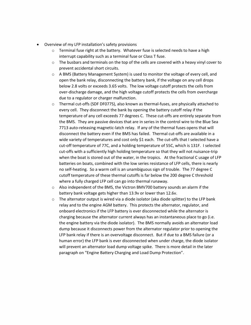
Above see string of eight SDF DF077S 77 deg C thermal cut-offs in series. These are the inexpensive ($1
each), passive, non-resettable thermal cut-offs often seen in hair-dryers, coffee-makers, electric heaters,
and similar appliances with heating elements. The string is taped along the battery with one cut-off
attached to each cell. The string is in series with the control wire to the main battery relay. If a thermal
cutoff triggers, the battery is disconnected, independent of the BMS, or of any other electronics.
CALB
o CALB CA cells appear to be a good choice.
o They apparently maintain balance well and have a long life.
o Note for high latitude cruisers: LFP batteries must not be charged if they are below 0
deg C. Their discharge and storage range extends to -20 deg C.
Pack design
o My battery is configured 2P4S, or as four groups of two cells in parallel, with the four
groups in series. I used eight CA180LI cells, yielding a 360AH battery.
o Each group of two parallel cells is connected on its diagonals, into the series string, as is
customary in battery design, in order for each cell in the bank to have the same busbar
series resistance.
o I chose to use braided busbars from evtv.me because they are slightly flexible and
reduce the mechanical loads on the battery terminals.
o McMaster carries M8 x 1.25 SS bolts that are 16, 18, 20, 22, 25 mm long which are
handy to deal with the varying thickness of the busbars and terminals and still use most
of the threads in the battery poles which are made of soft aluminum or copper
depending on the pole.
o I made 5/16 inch G10 end plates, and strapped the battery together with Kevlar straps.
I chose Kevlar over SS banding to avoid conductive banding in the proximity of the
battery. Some say that it isn’t necessary to have strapped endplates in the low current
application onboard boats, but CALB recommends the practice. Sally also had some left-
over Kevlar strap from her sail loft so it was easy.
o CALB recommends to lightly sand the battery terminals. I sanded and then coated the
terminals and busbars lightly with No-ox-id Special-A. Noalox is another, messier,
alternative.
o Sally made a vinyl cover for the assembled battery to prevent accidental shorting of the
cell busbar interconnects which have no fuse protection.
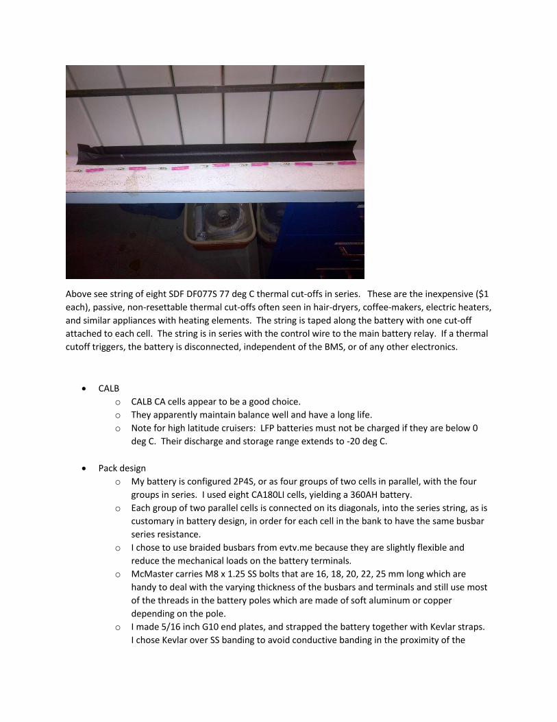
o The manufacturer CALB recommends that the cells be mounted terminals-up. Others
have mounted cells with a narrow-side down with no apparent problems but mounting
terminals-down or flat-side-down is ill-advised because it would disable the vents. My
battery is mounted with the cells having a narrow side down. The cells are actually
tipped up some because of the dead-rise in the hull.
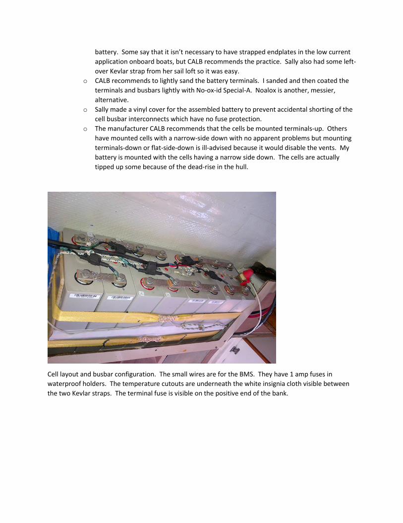
Cell layout and busbar configuration. The small wires are for the BMS. They have 1 amp fuses in
waterproof holders. The temperature cutouts are underneath the white insignia cloth visible between
the two Kevlar straps. The terminal fuse is visible on the positive end of the bank.
BMS
o I used the Cleanpowerauto Housepower BMS and the 4S remote cellboard. Note that
these BMS parts are no longer available. If I have to update the BMS I would select one
that does not need to have cellboards mounted on the battery.
o I ordered a board with HVC set for 14.2 volts. The standard board comes with HVC set
for 14.6. The website documentation isn’t perfectly clear so one needs to specify. As
you can conclude from the 14.2 HVC setting, I’m not planning to use the BMS for
balancing, but instead am using it as a safety mechanism to disconnect the battery
before a cell gets damaged due to too high or too low voltage (above 3.65v or below
2.8v).
o I used the 4S remote cellboard instead of the individual cell boards so that the 4S
cellboard could be mounted in a waterproof nema box adjacent to the battery, also
containing the bms board, HVC relay, and alarm. All switches, cable glands, and other
penetrations into the nema box are waterproof. LFP batteries are heavy enough so that
they are sensibly mounted low in a boat, i.e. in the bilge. Things that are mounted in
the bilge get wet and dirty. One drop of salt water or a small metal shaving on a cell
board could ruin the surface mount circuit board, so I chose to not mount fragile bms
boards on the cells themselves but instead mount them and all other delicate items
inside the waterproof nema box. All parts mounted outside the sealed nema box are
reasonably tolerant of moisture and dirt (e.g. relay, shunt, fuse, potted regulator).
o The 14.2 HV and 11.6 LV bank voltage alarms from the BMS are unlikely to ever trigger
because the Victron BMV700 that I use as an amp-hour meter is set up to sound the
alarm if the bank voltage gets above 13.9v or below 12.6v. So the Victron will trigger a
bank voltage alarm before the BMS on high or low battery bank voltage.
Regulator
o Nearly any sufficiently configurable smart regulator could be programmed to work. I
use 13.8 volt bulk voltage, no temperature compensation, and a low float voltage.
o I used a Balmar MC-614 which is very configurable. It will refresh your fond memories
of 1970’s era user interfaces. I set up the Balmar MC-614 with the following settings:
dLc 30 sec
AHL 13.9 volt
CL 13.9 volt
bv 13.8 Volt
b1c 0.2 (shortest possible)
Av 13.6 Volt
A1c 0.2 (shortest possible)
Fv 13.4 Volt
F1c 6 Hours (longest possible)
FbA 10
SLP 0.4 mVolt (minimum possible)
bEL b-9 belt manager
o There is a widely known trick with the Balmar regulators when lowering the set
voltages: you have to reduce the float voltage first, then reduce the absorption, then
the bulk.
o With this configuration, charging takes place in “bulk”, the unnecessary “absorption”
phase gets passed through quickly, and the regulator shuts off charging when it switches
to the low 13.4v “float” charge. The alternator does carry any DC loads when the
regulator is in the float state because 13.4 is very close to the open circuit voltage of 4
LFP cells in series (4*3.34=13.36v).
o I connect the power wire for the regulator via a relay controlled by the high-voltage-
cutoff output of the BMS, so that the regulator is disabled if the BMS detects a bank
voltage of 14.2 or higher, or a cell voltage of 3.65 or higher.
o I have a manual toggle switch also in series with the power to the regulator to make it
easy to disable charging. LFP batteries are happiest stored at partial charge. As a result,
there are times when I want to run the engine without going through a charge cycle that
would fully charge the battery, e.g. motoring to a slip or boatyard before a period when
the boat will not be used. There are other times that we sometimes disable charging
such as low speed maneuvering in a marina, or when re-starting the engine when the
battery is already nearly fully charged.
o Some folks state that a 13.8 volt (3.45v per cell) bulk charge will not fully charge a LFP
battery. Whether it does or not depends on how low you let the charge current drop
before terminating charging. A 13.8 volt charging voltage will overcharge and damage a
LFP battery if you keep at it too long. With the MC-614 regulator settings that I use, the
regulator switches from “bulk” at 13.8v when the charge current drops below about 25
amps. At that point the charge current is dropping quickly. I estimate that the battery is
then charged to about 95% or more. In my case this conservative approach makes
sense because I don’t need the full 100% capacity of my bank and there are advantages
to only charging to 95% state of charge. One advantage is the cells stay perfectly
balanced. A second advantage is that the engine on a sailboat might be started several
times per day when the battery is charged already. With b1C set to minimum time, and
with a conservative “bulk” voltage of 13.8v, these “short cycles” do no harm. I
sometimes use the manual switch to disable charging in these situations but it is a
reasonable goal to have a charging system that doesn’t depend on manual intervention.
o Pet Peeve on terminology: Balmar’s terminology is unfortunate. For many years the
“bulk” phase was when the charge source was putting out as much as it could and the
voltage had not yet reached the “absorption” set voltage. The “absorption” phase was
when the battery voltage was at the voltage set point and the charge current was
decreasing. Finally “float” was when the smart regulator switched to a lower voltage.
By adding a new mystery phase and labelling it “absorption” with yet another voltage
set point, Balmar is just confusing things. But it does no harm. As mentioned I just set
A1c as short as possible so that the unnecessary Balmar “absorption” phase gets passed
through quickly.
Engine battery charging and Load Dump protection
o I use a Mastervolt Batterymate 1602 FET-based zero-voltage-drop “diode battery
isolator” (aka diode splitter). My engine battery is a Lifeline AGM, so the charge voltages
for the LFP battery are compatible. The Balmar MC-614 regulator is located adjacent to
the LFP battery with short and heavy ground and sense wires, so the LFP battery is at
precisely 13.8v during acceptance charging (or the CV portion of “bulk” in Balmar’s odd
terminology). The peak charge voltage is slightly higher (14.1v) for the Lifeline AGM
engine battery due to the IR drop in the battery cables to the LFP battery but it ends up
being perfect for the Lifeline AGM engine battery.
o Diode Isolators are not as fashionable these days as are ACR’s (Automatic Charge Relays)
but they have some advantages. The major advantage of the diode isolator is that if the
BMS (or a misguided human) ever disconnects the LFP battery when under charge, the
alternator current always has some instantaneous place to go (i.e. to the engine battery
via the diode isolator). Therefore there will never be an alternator load dump voltage
spike that could damage onboard electronics or the alternator diodes. The regulator
sense wire is connected to the output of the diode-isolator so if the BMS relay
disconnects the LFP battery the regulator will continue to sense the charging voltage as
the alternator continues to charge just the engine battery. Having the regulator sense
wire on the output of the diode-isolator also allows the regulator to compensate for the
voltage drop of the diode isolator. The use of a diode isolator results in more
predictable behavior than an ACR, is simpler than an ACR, and does not rely on a
mechanical relay. A diode isolator provides continuous protection against an alternator
load dump which an ACR does not if the ACR relay happened to be open when the LFP
bank disconnected. FET based “diode” isolators have much lower voltage drop than
diode isolators based on silicon diodes, so they don’t dissipate much heat.
o There are a couple of other advantages of diode isolators. One is that when the engine
is off, they keep the 12v from appearing on the back of the alternator, thus making
servicing the engine safer and making a “service” disconnect switch for the alternator
unnecessary. Another advantage is that if the alternator diodes were ever to fail
shorted, the diode isolator would prevent the failed alternator diodes from shorting a
battery to ground.
Alternator
o The high charge acceptance of a LFP battery can be tough on alternators. Normal
alternatives are to use a large-frame high-temperature rated alternator, use an
alternator temperature sensor with a regulator that limits field current accordingly, or
just limit alternator field current and run the alternator well below its maximum
capability.
o Many have observed that that small-frame alternators overheat if run continuously at
full output. I selected a Balmar AT-165 which has a significantly higher rated output
than I need. It is small-frame, fits easily on a Yanmar, and uses the Denso hairpin stator
which is said to be more efficient than a conventional winding. I run it at Balmar’s belt
manager setting of b-9, which is 55% of full-field. This setting limits the max alternator
current to about 110A which is close to 0.3C for my battery, which is the CALB
recommendation for charge current. The AT-165 is able to put out 110A continuously
without exceeding 220 deg F, even in the small Cal 40 engine space.
o I installed the Balmar serpentine belt kit. This was supposed to be a “plug-and-play”
installation on my Yanmar 3GM30FV, but wasn’t. I had to buy shorter belts (390J10),
machine the crankshaft sheave spacer to be 0.12 inch thinner, and put washers in the
saddle mount of the alternator to move it away from the engine 0.10 inch. After those
adjustments it worked perfectly and it’s terrific to have no belt dust. McMaster carries
many sizes of serpentine belts.
Shore charger (or shore power supply)
o When you are in a slip, plugged into shore power, you have to deal with LFP batteries
entirely differently than lead-acid batteries of any type (liquid, gel, or agm). Lead-acid
batteries of any type benefit from being float charged at 100% because it avoids
sulfation. LFP batteries are best stored at 50% charge or lower, and suffer if kept at
100%. This difference requires a significant change of attitude. With lead batteries on
float, the boat is always “ready-to-go” with fully charged batteries. With LFP batteries
that are around 50% charge, you have to either charge them before departure, rely on
them getting mostly charged by the engine as part of powering out of the slip and
hoisting sails, or be happy to leave the slip with batteries that are not fully charged.
o I use a high-quality, regulated, remote-sensing, low-ripple, DC power supply (Kepco RTW
15-20KC). I can use it to charge the battery if there is a need. Normally when the boat
is in a marina/slip with shore power available and we are onboard, I leave the LFP
battery disconnected at about 50% state of charge, and use the DC power supply to
power the boat’s electrical system directly with no battery in parallel.
o If DC power supplies are to be capable of charging batteries, they need to have
“rectangular current limiting”, or “constant current limiting” which are obscure ways to
say that the power supply needs to be able to run continuously at its current limit when
it can’t reach its voltage set point. The Kepco RTW 15-20KC has this property and has a
wide input range of 85-265 VAC, 47-440 Hz, which is helpful if the boat ends up
overseas, at the end of a long dock with low voltage, or if I ever have to charge from a
cheap, unregulated, portable generator.
o The Kepco power supply is electrically quiet (+- 0.05v output ripple, FCC Class B) and has
terminals for remote voltage sense. These are advantages offered by only the best
marine battery chargers. Kepco power supplies also have the characteristic that all well
designed DC power supplies have, that it is fine to have their output hooked to a battery
when their AC input is unpowered.
Battery and charge monitoring
o LFP batteries have an extremely flat charge/voltage curve, so the measurement of bank
voltage cannot be used to determine the state of charge the way it can with a lead-acid
battery.
o I use a Victron BMV700 as an amp-hour meter to track state of charge, but there are lots
of options.
I set up the Victron to sound an alarm of the battery voltage exceeds 13.9 or
drops below 12.6. (This is independent from, and will sound earlier than, the
BMS bank voltage alarms at 14.2 and 11.6)
o LFP batteries are extremely efficient so I set the charge efficiency factor to 100% and the
Peukert exponent to 1.0. These settings cause the Victron amp-hour meter to estimate
that the battery is fully charged just slightly before the end of each full charge cycle.
This causes the Victron amp-hour meter to reset to 0 (i.e. full) with each full charge, and
so stay synchronized.
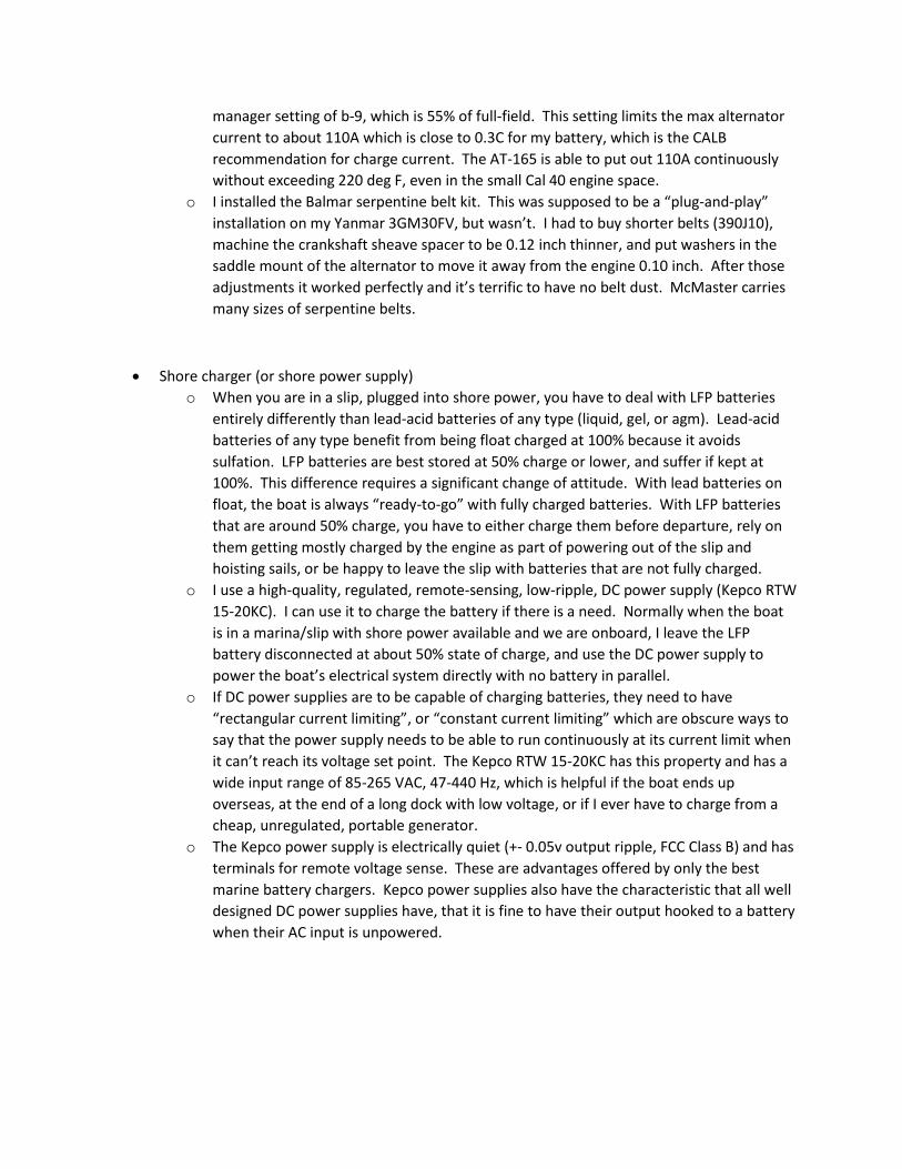
Above, G10 board that holds associated battery electronics: the BMS, HVC relay, and alarm are the Bud
box. The Balmar regulator, windlass circuit breaker, and Blue Sea 7713 auto-releasing relay controlled
by the BMS are more tolerant of moisture and so are mounted outside the Bud Box on the G10 plate.
The Victron BMV700 is in the lid of the Bud box, which isn’t in place in the above photo. The three
switches on the Bud Box are: bms reset (momentary), battery/bms on, and charge enable. The Bud box
and all cable penetrations, switches, and the alarm mounted through the box are all rated for being
waterproof.
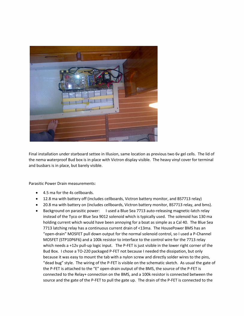
Final installation under starboard settee in Illusion, same location as previous two 6v gel cells. The lid of
the nema waterproof Bud box is in place with Victron display visible. The heavy vinyl cover for terminal
and busbars is in place, but barely visible.
Parasitic Power Drain measurements:
4.5 ma for the 4s cellboards.
12.8 ma with battery off (includes cellboards, Victron battery monitor, and BS7713 relay)
20.8 ma with battery on (includes cellboards, Victron battery monitor, BS7713 relay, and bms).
Background on parasitic power: I used a Blue Sea 7713 auto-releasing magnetic-latch relay
instead of the Tyco or Blue Sea 9012 solenoid which is typically used. The solenoid has 130 ma
holding current which would have been annoying for a boat as simple as a Cal 40. The Blue Sea
7713 latching relay has a continuous current drain of <13ma. The HousePower BMS has an
“open-drain” MOSFET pull down output for the normal solenoid control, so I used a P-Channel
MOSFET (STP10P6F6) and a 100k resistor to interface to the control wire for the 7713 relay
which needs a +12v pull-up logic input. The P-FET is just visible in the lower right corner of the
Bud Box. I chose a TO-220 packaged P-FET not because I needed the dissipation, but only
because it was easy to mount the tab with a nylon screw and directly solder wires to the pins,
“dead bug” style. The wiring of the P-FET is visible on the schematic sketch. As usual the gate of
the P-FET is attached to the “E” open-drain output of the BMS, the source of the P-FET is
connected to the Relay+ connection on the BMS, and a 100k resistor is connected between the
source and the gate of the P-FET to pull the gate up. The drain of the P-FET is connected to the
red control input wire of the Blue Sea 7713 relay, in series with the thermal cut-offs. The P-FET
uses no current beyond the 0.13 ma of the 100k pullup resistor. When controlling the Blue Sea
7713 there is no need for a “free-wheeling” or “flyback” diode because the control input to the
7713 is actually a logic input and not a relay coil so there is no inductance.
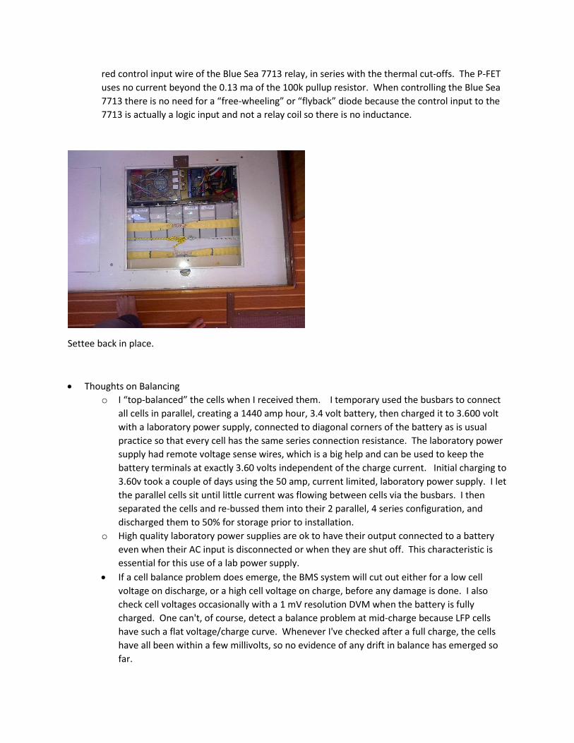
Settee back in place.
Thoughts on Balancing
o I “top-balanced” the cells when I received them. I temporary used the busbars to connect
all cells in parallel, creating a 1440 amp hour, 3.4 volt battery, then charged it to 3.600 volt
with a laboratory power supply, connected to diagonal corners of the battery as is usual
practice so that every cell has the same series connection resistance. The laboratory power
supply had remote voltage sense wires, which is a big help and can be used to keep the
battery terminals at exactly 3.60 volts independent of the charge current. Initial charging to
3.60v took a couple of days using the 50 amp, current limited, laboratory power supply. I let
the parallel cells sit until little current was flowing between cells via the busbars. I then
separated the cells and re-bussed them into their 2 parallel, 4 series configuration, and
discharged them to 50% for storage prior to installation.
o High quality laboratory power supplies are ok to have their output connected to a battery
even when their AC input is disconnected or when they are shut off. This characteristic is
essential for this use of a lab power supply.
If a cell balance problem does emerge, the BMS system will cut out either for a low cell
voltage on discharge, or a high cell voltage on charge, before any damage is done. I also
check cell voltages occasionally with a 1 mV resolution DVM when the battery is fully
charged. One can't, of course, detect a balance problem at mid-charge because LFP cells
have such a flat voltage/charge curve. Whenever I've checked after a full charge, the cells
have all been within a few millivolts, so no evidence of any drift in balance has emerged so
far.
If I did have a balance problem, there are three options to fix it:
1. I could fix it by re-bussing the cells in parallel again and charging to 3.600 volts. This
would only be a dockside exercise.
2. I carry onboard a 0.5 ohm 50W resistor as well as a 3.6v 6amp isolated-output
single-cell LFP charger with some clip leads. I could do a rough rebalancing after a
full charge, by just charging or discharging the unbalanced cell(s) one at a time to
get closer to the other cells. This could be done at sea. I have not tried this as the
cells have stayed in perfect balance so far.
3. In principle another approach would be to disable the HVC on the BMS, disable the
HV alarm on the Victron, and then charge at 1 amp or less for an extended period
letting the bank voltage rise to 14.2v. This would let the limited shunt capability (1
amp) of the cellboards slowly fix the imbalance. This is not an attractive option
because the 1 amp shunt current capability of the cellboards would require holding
the battery at a voltage of 14.2v for an extended period, which is tough on the
battery.
I haven’t had a balance problem but if I did I would probably use the second option above to
address it.
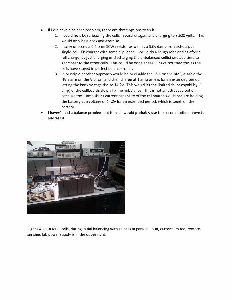
Eight CALB CA180FI cells, during initial balancing with all cells in parallel. 50A, current limited, remote
sensing, lab power supply is in the upper right.
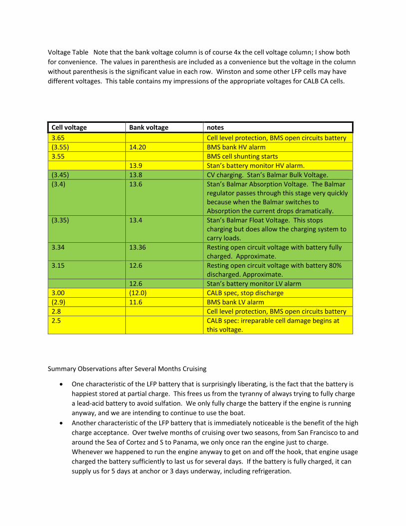
Voltage Table Note that the bank voltage column is of course 4x the cell voltage column; I show both
for convenience. The values in parenthesis are included as a convenience but the voltage in the column
without parenthesis is the significant value in each row. Winston and some other LFP cells may have
different voltages. This table contains my impressions of the appropriate voltages for CALB CA cells.
Cell voltage Bank voltage notes
3.65 Cell level protection, BMS open circuits battery
(3.55) 14.20 BMS bank HV alarm
3.55 BMS cell shunting starts
13.9 Stan’s battery monitor HV alarm.
(3.45) 13.8 CV charging. Stan’s Balmar Bulk Voltage.
(3.4) 13.6 Stan’s Balmar Absorption Voltage. The Balmar regulator passes through this stage very quickly because when the Balmar switches to Absorption the current drops dramatically.
(3.35) 13.4 Stan’s Balmar Float Voltage. This stops charging but does allow the charging system to carry loads.
3.34 13.36 Resting open circuit voltage with battery fully charged. Approximate.
3.15 12.6 Resting open circuit voltage with battery 80% discharged. Approximate.
12.6 Stan’s battery monitor LV alarm
3.00 (12.0) CALB spec, stop discharge
(2.9) 11.6 BMS bank LV alarm
2.8 Cell level protection, BMS open circuits battery
2.5 CALB spec: irreparable cell damage begins at this voltage.
Summary Observations after Several Months Cruising
One characteristic of the LFP battery that is surprisingly liberating, is the fact that the battery is
happiest stored at partial charge. This frees us from the tyranny of always trying to fully charge
a lead-acid battery to avoid sulfation. We only fully charge the battery if the engine is running
anyway, and we are intending to continue to use the boat.
Another characteristic of the LFP battery that is immediately noticeable is the benefit of the high
charge acceptance. Over twelve months of cruising over two seasons, from San Francisco to and
around the Sea of Cortez and S to Panama, we only once ran the engine just to charge.
Whenever we happened to run the engine anyway to get on and off the hook, that engine usage
charged the battery sufficiently to last us for several days. If the battery is fully charged, it can
supply us for 5 days at anchor or 3 days underway, including refrigeration.

We have no additional charge sources such as wind or solar. Given our experience so far we see
no need to add additional charge sources and their associated clutter on deck. Our occasional
use of the engine for propulsion and the high charge acceptance keeps up with our energy use.
Living on shore-power in a slip is different. We discharge the LFP battery to 50%, disconnect the
battery, and then run the boat off of a DC power supply connected to shore-power.
The cells have stayed in perfect balance so far.