Staircase Design Report
23
Design Project 1 Ryland Ballingham Ryan Rampolla Group 44 9/25/15 Dr.Griffis
-
Upload
ryland-ballingham -
Category
Documents
-
view
292 -
download
3
Transcript of Staircase Design Report
Design Project 1
Ryland Ballingham
Ryan Rampolla
Group 44
9/25/15
Dr.Griffis

Contents Need .............................................................................................................................................................. 3
Specs ............................................................................................................................................................. 3
Concepts ....................................................................................................................................................... 4
Introduction .............................................................................................................................................. 4
How it works ............................................................................................................................................. 6
Features .................................................................................................................................................... 6
Analysis & Optimization ................................................................................................................................ 7
Evaluation ................................................................................................................................................... 22
References .................................................................................................................................................. 22

Need Preliminary Need:
There is a need for easy access between two floors within a household.
Design Considerations:
1. Safety
2. Standards and building codes
3. Load rating
4. Overall size
5. Stress conditions (nominal worst case)
6. Overall Factor of Safety
7. Ease of use
8. Material choice
9. Ease of manufacture
10. Shape and size (geometry)
Specs Performance Specs
1. Capacity (max weight of user): 300 lbf at the center of the step
2. Constraint imposed:
a. 270° sweep for garden
3. Staircase Code:
a. Overall height: 10ft
b. Minimum step length: 26in
c. Maximum rise between steps: 9.5 in
d. Each tread having a 7.5 inch minimum tread depth at12 inches from
the narrower edge.
e. Minimum headroom of 6’6’’

Concepts
Introduction
The design concept is a fairly simple design composing of 12 steps constructed out of
steel with a rise on 9.5 in. Each step in the concept had on overall step length of 26 in and
a tread depth of 8.04 in at a distance of 12 in from the narrower edge. The overall
assembly is broken down into four parts: The steps/center pole, the under step bracket
(including two ¾”-10 fasteners), the supporting pipe and the pole bracket (including two
¾”-10 fasteners). The center pole diameter is 6 in
step
Support pipe
Pipe to pole
bracket
Center pole
Figure 1: Step assembly

Figure 2: Bracket Assembly
Figure 3: Step assembly exploded
¾”-16 bolts
¾”-10 bolts
¾”-16
nuts
¾”-10 nuts
Under step
bracket
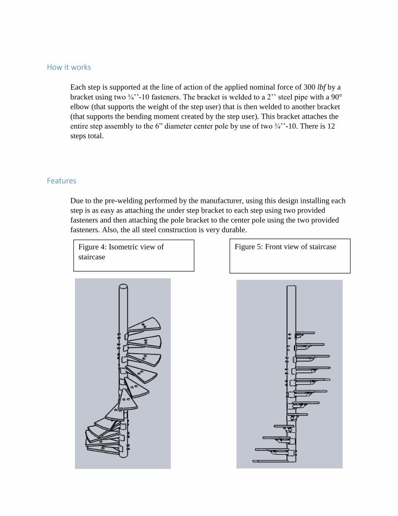
How it works
Each step is supported at the line of action of the applied nominal force of 300 lbf by a
bracket using two ¾’’-10 fasteners. The bracket is welded to a 2’’ steel pipe with a 90°
elbow (that supports the weight of the step user) that is then welded to another bracket
(that supports the bending moment created by the step user). This bracket attaches the
entire step assembly to the 6” diameter center pole by use of two ¾’’-10. There is 12
steps total.
Features
Due to the pre-welding performed by the manufacturer, using this design installing each
step is as easy as attaching the under step bracket to each step using two provided
fasteners and then attaching the pole bracket to the center pole using the two provided
fasteners. Also, the all steel construction is very durable.
Figure 4: Isometric view of
staircase
Figure 5: Front view of staircase

Analysis & Optimization
The purpose of the following analysis is to determine whether or not our design will
support the given nominal load of 300 lbf. With a factor of safety of n > 1. The line of
action of the applied nominal load will act in the middle of the step (half the distance to
the step edge.
In the following, the staircase is going to be analyzed using free body diagrams. Free
body diagrams will allow us to solve for unknown reaction forces, moments, bolt forces,
weld stresses that will occur at these critical locations. This will allow us to ensure that
we have created a safe and reliable design. We will choose two critical locations to
analyze, the weld that connects the pipe to the pole mounting bracket and the weld right
before the elbow on the pipe.
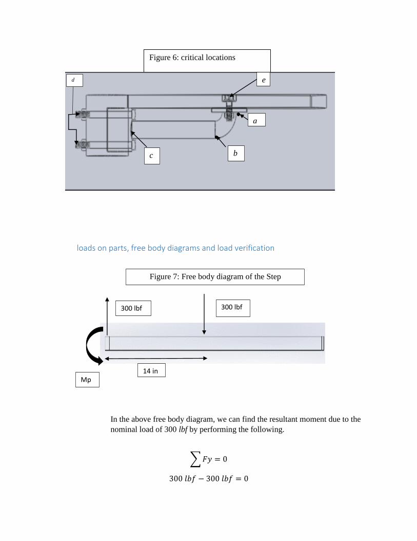
critical locations
Table 1
Location Failure concern Rational
a buckling (compressive) Weaker material, high contact stress
b tear (tensile) High bending moment , weaker material (weld)
c tear (tensile) High bending moment , weaker material (weld)
d tear (tensile) High bending moment, high shear stress, small
cross sectional area
f buckling (compressive) High contact stress, small cross-sectional area
loads on parts, free body diagrams and load verification
In the above free body diagram, we can find the resultant moment due to the
nominal load of 300 lbf by performing the following.
∑ 𝐹𝑦 = 0
300 𝑙𝑏𝑓 − 300 𝑙𝑏𝑓 = 0
14 in Mp
300 lbf 300 lbf
Figure 7: Free body diagram of the Step
Figure 6: critical locations
a
b c
e d
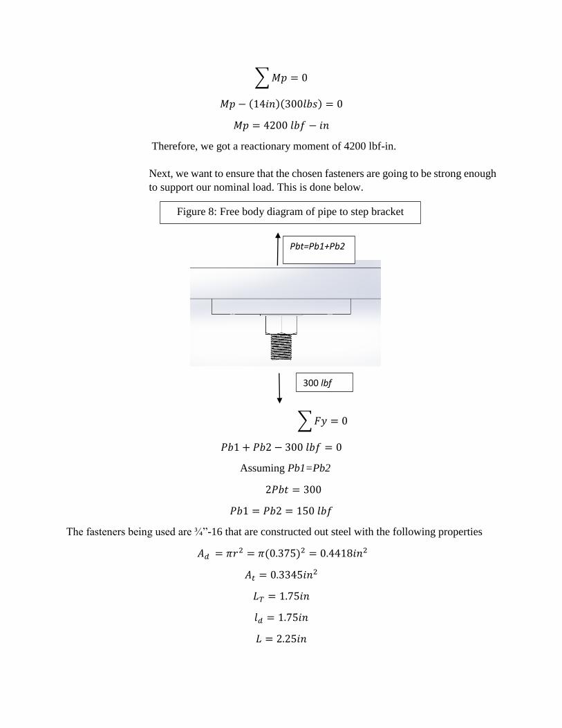
∑ 𝑀𝑝 = 0
𝑀𝑝 − (14𝑖𝑛)(300𝑙𝑏𝑠) = 0
𝑀𝑝 = 4200 𝑙𝑏𝑓 − 𝑖𝑛
Therefore, we got a reactionary moment of 4200 lbf-in.
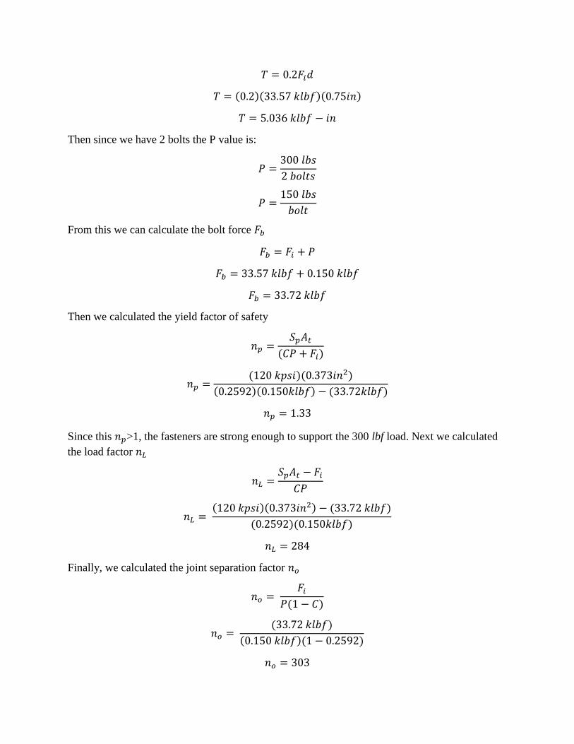
Next, we want to ensure that the chosen fasteners are going to be strong enough
to support our nominal load. This is done below.
∑ 𝐹𝑦 = 0
𝑃𝑏1 + 𝑃𝑏2 − 300 𝑙𝑏𝑓 = 0
Assuming Pb1=Pb2
2𝑃𝑏𝑡 = 300
𝑃𝑏1 = 𝑃𝑏2 = 150 𝑙𝑏𝑓
The fasteners being used are ¾”-16 that are constructed out steel with the following properties
𝐴𝑑 = 𝜋𝑟2 = 𝜋(0.375)2 = 0.4418𝑖𝑛2
𝐴𝑡 = 0.3345𝑖𝑛2
𝐿𝑇 = 1.75𝑖𝑛
𝑙𝑑 = 1.75𝑖𝑛
𝐿 = 2.25𝑖𝑛
Pbt=Pb1+Pb2
300 lbf
Figure 8: Free body diagram of pipe to step bracket

𝑙𝑡 = 𝑙 − 𝑙𝑑 = 0.75𝑖𝑛
𝐸 = 30 𝑀𝑝𝑠𝑖
First, we found the member stiffness constant 𝐾𝑚
𝐾𝑚 =0.5774𝜋𝐸𝑑
2ln (5(0.5774𝑙 + 0.5𝑑)0.5774𝑙 + 2.5𝑑
𝐾𝑚 =0.5774𝜋(30𝑀𝑝𝑠𝑖)(0.75𝑖𝑛)
2ln (5(0.5774(1.25𝑖𝑛) + 0.5(0.75𝑖𝑛))0.5774(1.25𝑖𝑛) + 2.5(0.75𝑖𝑛)
𝐾𝑚 = 27.30 𝑀𝑙𝑏𝑓
𝑖𝑛⁄
Next, we found the bolt stiffness constant 𝐾𝑏
𝐾𝑏 = 𝐴𝑑𝐴𝑡𝐸
𝐴𝑑𝑙𝑡 + 𝐴𝑡𝑙𝑑
𝐾𝑏 = (0.442𝑖𝑛)(0.373𝑖𝑛)(30𝑀𝑝𝑠𝑖)
(0.373𝑖𝑛)(0.75𝑖𝑛) + (0.373𝑖𝑛2)(0.5𝑖𝑛)
𝐾𝑏 = 9.55 𝑀𝑙𝑏𝑓
𝑖𝑛⁄
Then we found the joint stiffness constant C
𝐶 =𝐾𝑏
𝐾𝑏 + 𝐾𝑚
𝐶 =9.55
𝑀𝑙𝑏𝑓𝑖𝑛⁄
9.55 𝑀𝑙𝑏𝑓
𝑖𝑛⁄ + 27.30 𝑀𝑙𝑏𝑓
𝑖𝑛⁄
𝐶 = 0.2592
Then we calculated the desired preload 𝐹𝑖 of the nut
𝐹𝑖 =3
4𝑆𝑝𝐴𝑡
𝐹𝑖 =3
4(120 𝑘𝑝𝑠𝑖)(0.373 𝑖𝑛2)
𝐹𝑖 = 33.57 𝑘𝑙𝑏𝑓
Then the fastener torque T
𝑇 = 0.2𝐹𝑖𝑑
𝑇 = (0.2)(33.57 𝑘𝑙𝑏𝑓)(0.75𝑖𝑛)
𝑇 = 5.036 𝑘𝑙𝑏𝑓 − 𝑖𝑛
Then since we have 2 bolts the P value is:
𝑃 =300 𝑙𝑏𝑠
2 𝑏𝑜𝑙𝑡𝑠
𝑃 =150 𝑙𝑏𝑠
𝑏𝑜𝑙𝑡
From this we can calculate the bolt force 𝐹𝑏
𝐹𝑏 = 𝐹𝑖 + 𝑃
𝐹𝑏 = 33.57 𝑘𝑙𝑏𝑓 + 0.150 𝑘𝑙𝑏𝑓
𝐹𝑏 = 33.72 𝑘𝑙𝑏𝑓
Then we calculated the yield factor of safety
𝑛𝑝 =𝑆𝑝𝐴𝑡
(𝐶𝑃 + 𝐹𝑖)
𝑛𝑝 =(120 𝑘𝑝𝑠𝑖)(0.373𝑖𝑛2)
(0.2592)(0.150𝑘𝑙𝑏𝑓) − (33.72𝑘𝑙𝑏𝑓)
𝑛𝑝 = 1.33
Since this 𝑛𝑝>1, the fasteners are strong enough to support the 300 lbf load. Next we calculated
the load factor 𝑛𝐿
𝑛𝐿 =𝑆𝑝𝐴𝑡 − 𝐹𝑖
𝐶𝑃
𝑛𝐿 = (120 𝑘𝑝𝑠𝑖)(0.373𝑖𝑛2) − (33.72 𝑘𝑙𝑏𝑓)
(0.2592)(0.150𝑘𝑙𝑏𝑓)
𝑛𝐿 = 284
Finally, we calculated the joint separation factor 𝑛𝑜
𝑛𝑜 = 𝐹𝑖
𝑃(1 − 𝐶)
𝑛𝑜 = (33.72 𝑘𝑙𝑏𝑓)
(0.150 𝑘𝑙𝑏𝑓)(1 − 0.2592)
𝑛𝑜 = 303
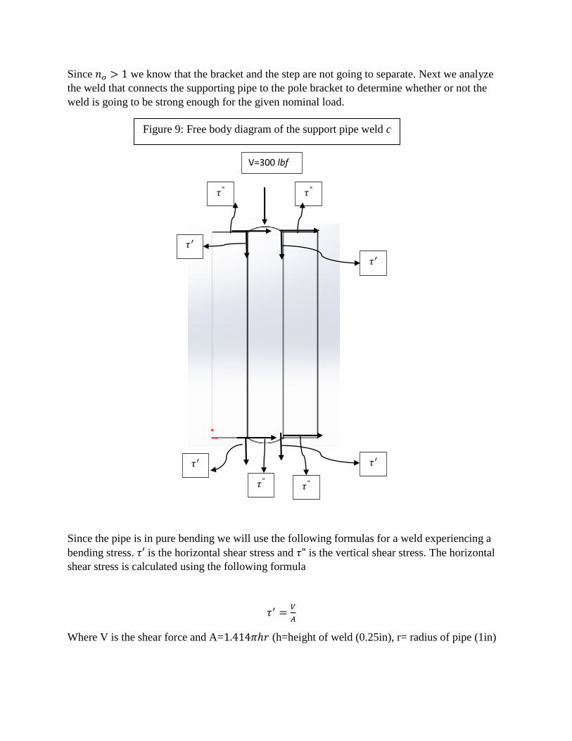
Since 𝑛𝑜 > 1 we know that the bracket and the step are not going to separate. Next we analyze
the weld that connects the supporting pipe to the pole bracket to determine whether or not the
weld is going to be strong enough for the given nominal load.
Since the pipe is in pure bending we will use the following formulas for a weld experiencing a
bending stress. 𝜏′ is the horizontal shear stress and 𝜏" is the vertical shear stress. The horizontal
shear stress is calculated using the following formula
𝜏′ =𝑉
𝐴
Where V is the shear force and A=1.414𝜋ℎ𝑟 (h=height of weld (0.25in), r= radius of pipe (1in)
𝜏" 𝜏"
𝜏′
𝜏′
𝜏′
𝜏" 𝜏"
𝜏′
V=300 lbf
Figure 9: Free body diagram of the support pipe weld c
𝜏′ =300 𝑙𝑏𝑓
1.1106𝑖𝑛2
𝜏′ = 270 𝑝𝑠𝑖
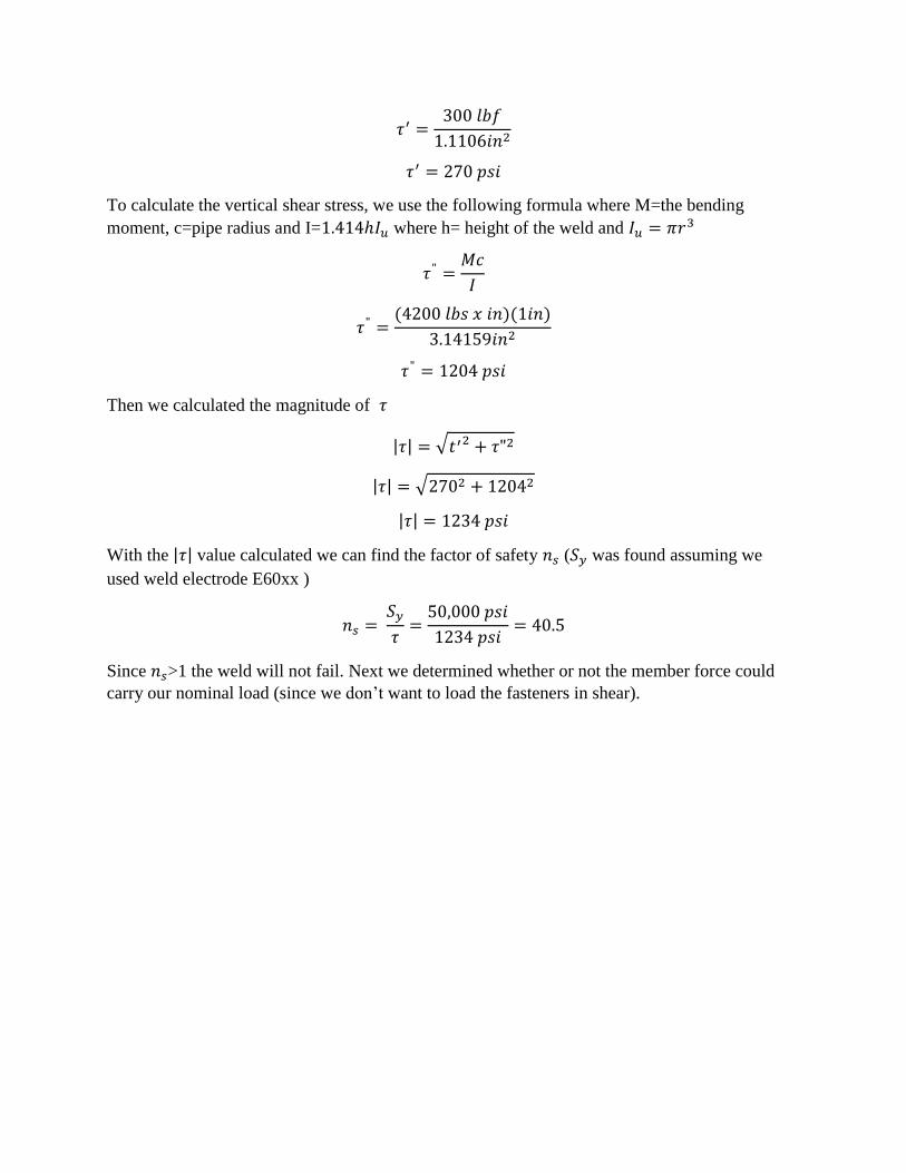
To calculate the vertical shear stress, we use the following formula where M=the bending
moment, c=pipe radius and I=1.414ℎ𝐼𝑢 where h= height of the weld and 𝐼𝑢 = 𝜋𝑟3
𝜏" =𝑀𝑐
𝐼
𝜏" =(4200 𝑙𝑏𝑠 𝑥 𝑖𝑛)(1𝑖𝑛)
3.14159𝑖𝑛2
𝜏" = 1204 𝑝𝑠𝑖
Then we calculated the magnitude of 𝜏
|𝜏| = √𝑡′2 + 𝜏"2
|𝜏| = √2702 + 12042
|𝜏| = 1234 𝑝𝑠𝑖
With the |𝜏| value calculated we can find the factor of safety 𝑛𝑠 (𝑆𝑦 was found assuming we
used weld electrode E60xx )
𝑛𝑠 = 𝑆𝑦
𝜏=
50,000 𝑝𝑠𝑖
1234 𝑝𝑠𝑖= 40.5
Since 𝑛𝑠>1 the weld will not fail. Next we determined whether or not the member force could
carry our nominal load (since we don’t want to load the fasteners in shear).

To start off with, we assumed that both bolt forces are equivalent (𝑃𝑏3= 𝑃𝑏4
). Because of this we
found an equivalent distance of the two bolts that is equidistant from the two true bolt distances.
This was done using the following formula.
𝑑𝑒 =3.125𝑖𝑛 + 1.125𝑖𝑛
2= 2.125𝑖𝑛
After we found the equivalent bolt distance 𝑑𝑒 then we summed the moments around point A
∑ 𝑀𝐴 = 0
−(14 𝑖𝑛)(300 𝑙𝑏𝑓) + (2.125𝑖𝑛)(𝑃𝑏𝑡) = 0
𝑃𝑏𝑡= 1976 𝑝𝑠𝑖
Since we are assuming that 𝑃𝑏3= 𝑃𝑏4
we can divide 𝑃𝑏𝑡 by 2
𝑃𝑏2= 𝑃𝑏2
=𝑃𝑏𝑡
2 𝑏𝑜𝑙𝑡𝑠=
1976 𝑝𝑠𝑖
2 𝑏𝑜𝑙𝑡𝑠= 988 𝑝𝑠𝑖
We can calculate the reaction force P caused by the bending moment created by the 300 lbf and
the two bolts by using the following formula.
𝑃 =𝑊𝐿
𝑑𝑒=
(300 𝑙𝑏𝑓)(14𝑖𝑛)
(2.125𝑖𝑛)= 1976 𝑝𝑠𝑖
Figure 10: Free body diagram of the entire step assembly
Pb3
3
Pb4
1.125in
3.125in
A
300 lbf 14 in
P
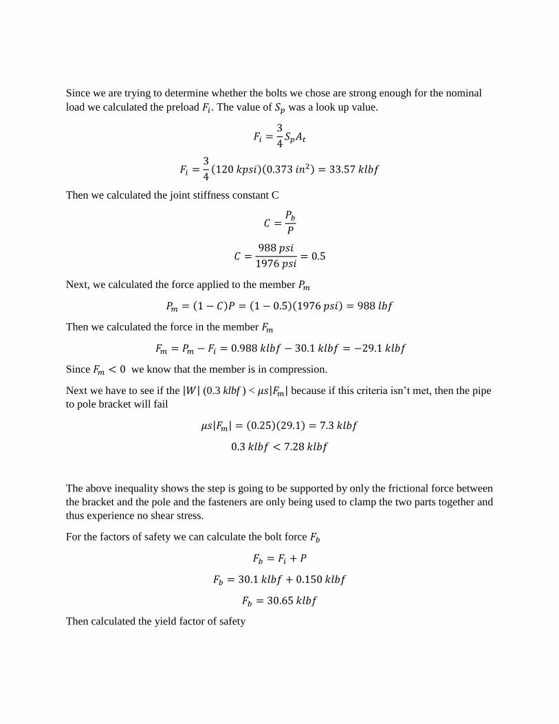
Since we are trying to determine whether the bolts we chose are strong enough for the nominal
load we calculated the preload 𝐹𝑖. The value of 𝑆𝑝 was a look up value.
𝐹𝑖 =3
4𝑆𝑝𝐴𝑡
𝐹𝑖 =3
4(120 𝑘𝑝𝑠𝑖)(0.373 𝑖𝑛2) = 33.57 𝑘𝑙𝑏𝑓
Then we calculated the joint stiffness constant C
𝐶 =𝑃𝑏
𝑃
𝐶 =988 𝑝𝑠𝑖
1976 𝑝𝑠𝑖= 0.5
Next, we calculated the force applied to the member 𝑃𝑚
𝑃𝑚 = (1 − 𝐶)𝑃 = (1 − 0.5)(1976 𝑝𝑠𝑖) = 988 𝑙𝑏𝑓
Then we calculated the force in the member 𝐹𝑚
𝐹𝑚 = 𝑃𝑚 − 𝐹𝑖 = 0.988 𝑘𝑙𝑏𝑓 − 30.1 𝑘𝑙𝑏𝑓 = −29.1 𝑘𝑙𝑏𝑓
Since 𝐹𝑚 < 0 we know that the member is in compression.
Next we have to see if the |𝑊| (0.3 klbf ) < 𝜇𝑠|𝐹𝑚| because if this criteria isn’t met, then the pipe
to pole bracket will fail
𝜇𝑠|𝐹𝑚| = (0.25)(29.1) = 7.3 𝑘𝑙𝑏𝑓
0.3 𝑘𝑙𝑏𝑓 < 7.28 𝑘𝑙𝑏𝑓
The above inequality shows the step is going to be supported by only the frictional force between
the bracket and the pole and the fasteners are only being used to clamp the two parts together and
thus experience no shear stress.
For the factors of safety we can calculate the bolt force 𝐹𝑏
𝐹𝑏 = 𝐹𝑖 + 𝑃
𝐹𝑏 = 30.1 𝑘𝑙𝑏𝑓 + 0.150 𝑘𝑙𝑏𝑓
𝐹𝑏 = 30.65 𝑘𝑙𝑏𝑓
Then calculated the yield factor of safety
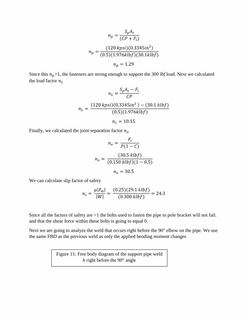
𝑛𝑝 =𝑆𝑝𝐴𝑡
(𝐶𝑃 + 𝐹𝑖)
𝑛𝑝 =(120 𝑘𝑝𝑠𝑖)(0.3345𝑖𝑛2)
(0.5)(1.976𝑘𝑙𝑏𝑓)(30.1𝑘𝑙𝑏𝑓)
𝑛𝑝 = 1.29
Since this 𝑛𝑝>1, the fasteners are strong enough to support the 300 lbf load. Next we calculated
the load factor 𝑛𝐿
𝑛𝐿 =𝑆𝑝𝐴𝑡 − 𝐹𝑖
𝐶𝑃
𝑛𝐿 = (120 𝑘𝑝𝑠𝑖)(0.3345𝑖𝑛2 ) − (30.1 𝑘𝑙𝑏𝑓)
(0.5)(1.976𝑘𝑙𝑏𝑓)
𝑛𝐿 = 10.15
Finally, we calculated the joint separation factor 𝑛𝑜
𝑛𝑜 = 𝐹𝑖
𝑃(1 − 𝐶)
𝑛𝑜 = (30.5 𝑘𝑙𝑏𝑓)
(0.150 𝑘𝑙𝑏𝑓)(1 − 0.5)
𝑛𝑜 = 30.5
We can calculate slip factor of safety
𝑛𝑠 = 𝜇|𝐹𝑚|
|𝑊|=
(0.25)(29.1 𝑘𝑙𝑏𝑓)
(0.300 𝑘𝑙𝑏𝑓)= 24.3
Since all the factors of safety are >1 the bolts used to fasten the pipe to pole bracket will not fail.
and that the shear force within these bolts is going to equal 0.
Next we are going to analyze the weld that occurs right before the 90° elbow on the pipe. We use
the same FBD as the previous weld as only the applied bending moment changes
Figure 11: Free body diagram of the support pipe weld
h right before the 90° angle

Note: 𝜏′ = horizontal shear stress and 𝜏" = vertical shear stress
As before, this weld is experiencing pure bending. The horizontal shear stress is calculated using
the following formula
𝜏′ =𝑉
𝐴
Where V is the shear force and A=1.414𝜋ℎ𝑟 (h=height of weld (0.25in), r= radius of pipe (1in)
𝜏′ =300 𝑙𝑏𝑓
1.1106𝑖𝑛2
𝜏′ = 270 𝑝𝑠𝑖
To calculate the vertical shear stress, we use the following formula where M=the bending
moment, c=pipe radius and I=1.414ℎ𝐼𝑢 where h= height of the weld and 𝐼𝑢 = 𝜋𝑟3
𝜏" =𝑀𝑐
𝐼
𝜏" 𝜏"
𝜏′
𝜏′
𝜏′
𝜏" 𝜏"
𝜏′
V=300 lbf

𝑀 = (2𝑖𝑛)(300 𝑙𝑏𝑓) = 600 𝑙𝑏𝑓 𝑥 𝑖𝑛
𝜏" =(600 𝑙𝑏𝑠 𝑥 𝑖𝑛)(1𝑖𝑛)
3.14159𝑖𝑛2
𝜏" = 191 𝑝𝑠𝑖
Then we calculated the magnitude of 𝜏
|𝜏| = √𝑡′2 + 𝜏"2
|𝜏| = √2702 + 1912
|𝜏| = 331 𝑝𝑠𝑖
With the |𝜏| value calculated we can find the factor of safety 𝑛𝑠 (𝑆𝑦 was found assuming we
used weld electrode E60xx )
𝑛𝑠 = 𝑆𝑦
𝜏=
50,000 𝑝𝑠𝑖
331 𝑝𝑠𝑖= 151
Since 𝑛𝑠>1 the weld will not fail.
Solid Works verification of load capacity
A static simulation was performed in Solid Works on the bracket assembly represented by Figure
2. To begin, the shell features of the connecting pipe were set to a thickness of 0.154”. This is
the wall thickness of a 2” schedule 40 steel pipe. Next the default global connection bond was
deleted in order to define the exact weld connections. Edge welds were placed on the pipe at
critical location points c, h, and a in Figure 3. Edge welds at c and a were 0.25” single fillet
welds with an E60 electrode, the weld at h was a 0.25” grove edge weld also with an E60
electrode. The bracket assembly was fixed by using a “fixed geometry” fixture on the back face
of the curved bracket that connects the pipe to the central staircase pole. Finally a 300lb vertical
forced was placed on the top face of the under-step bracket to simulate the force of someone
stepping on the nominal worst case of the step.
Table 2
Variable Weld c Weld h
Shear (psi) 𝜏 988.1 ≈ 400
Factor of Safety n 4.2 4.2
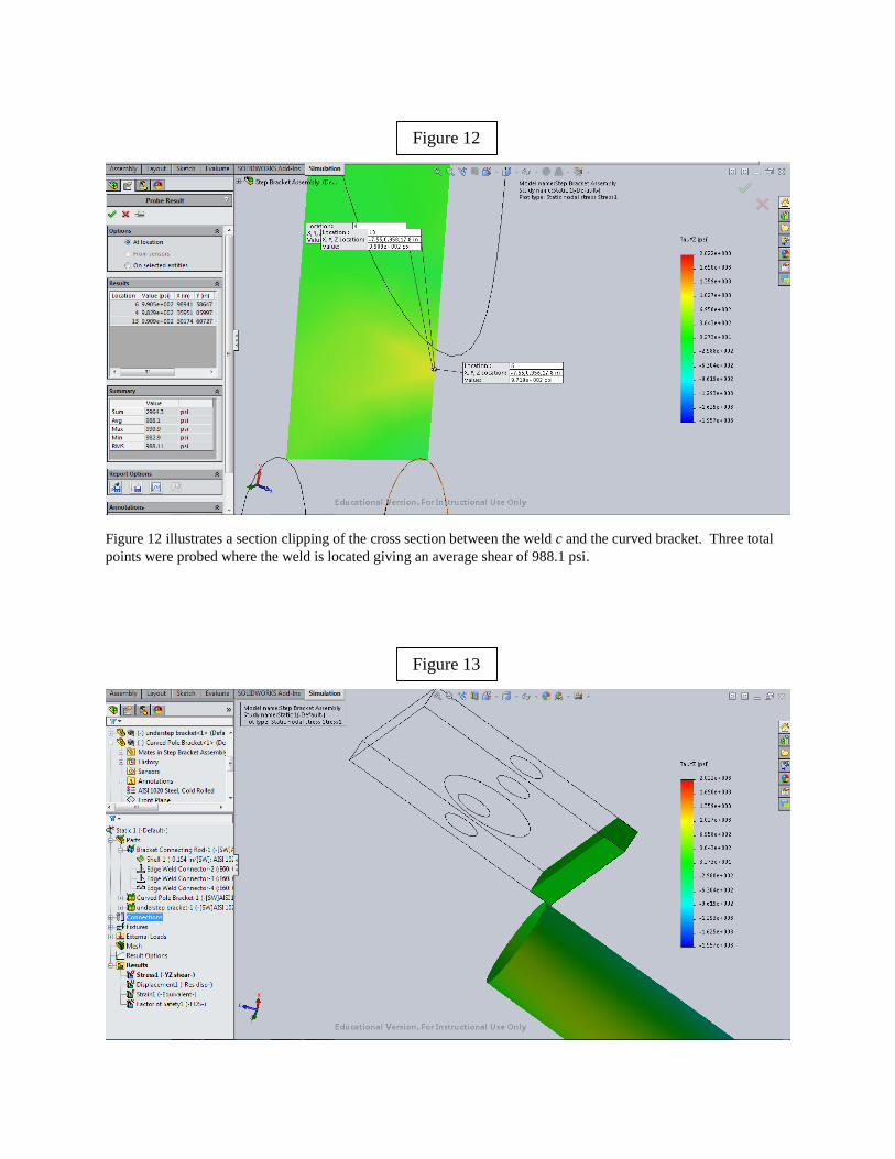
Figure 12 illustrates a section clipping of the cross section between the weld c and the curved bracket. Three total
points were probed where the weld is located giving an average shear of 988.1 psi.
Figure 12
Figure 13

Figure 13 illustrates the section clipping where weld h is located. The geometry of the thin pipe restricted probing
of the weld area. However, from the image it can be assumed that the shear is approximately 400 psi when
comparing the green/yellow pipe edge to the key on the right.
Figure 14 represents the Factor of Safety of the weld areas. From this image it can be determined from the
description in the top left that the minimum FOS in the entire assembly is 4.2 which is illustrated by the darkest red
on the scale to the right. Therefore when comparing the shade of red on the pipe where the welds are located, it is
clear that the entire pipe is the minimum FOS of 4.2.
Verification comparison
The table shown below compares the theoretical values with the SW model
Table 3
Weld c
variable Theoretical Solid Works Relative error
𝜏 1234 psi 988 psi 24.9%
𝑛𝑠 40.5 4.2 864%
Figure 14
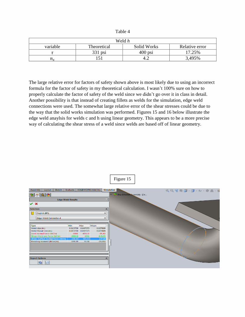
Table 4
Weld h
variable Theoretical Solid Works Relative error
𝜏 331 psi 400 psi 17.25%
𝑛𝑠 151 4.2 3,495%
The large relative error for factors of safety shown above is most likely due to using an incorrect
formula for the factor of safety in my theoretical calculation. I wasn’t 100% sure on how to
properly calculate the factor of safety of the weld since we didn’t go over it in class in detail.
Another possibility is that instead of creating fillets as welds for the simulation, edge weld
connections were used. The somewhat large relative error of the shear stresses could be due to
the way that the solid works simulation was performed. Figures 15 and 16 below illustrate the
edge weld anaylsis for welds c and h using linear geometry. This appears to be a more precise
way of calculating the shear stress of a weld since welds are based off of linear geometry.
Figure 15

Evaluation
The point of this section is to see whether or not our staircase met specs and is safe. Since
all the factors of safety are greater than the target value of 1 (theoretical and SW) and that
we are within the building code, we can conclude that our design is safe.
References
[1] Budynas and Nisbett, 2011, SHIGLEY’S MECHANICAL ENGINEERING DESIGN, 9th ed,
McGraw-Hill, NewYork.
[2] M. Griffis, 2014, EML3005 Fall 2015 Lectures.
[3] www.mcnichols.com, Schedule 40 thickness pipe dimension table
Figure 16